Loading ...
Loading ...
Loading ...
31
ELECTRICAL WORK
Fig.61
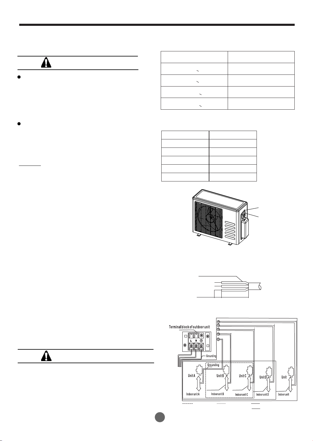
Connect the cable to the outdoor unit
1. Remove the electrical control board cover
from the outdoor unit by loosening the screw
as shown in Fig.61
2. Connect the connective cables to the
terminals as identified with their respective
matched numbers on the terminal block of
indoor and outdoor units.
3. Secure the cable onto the control board with
the cord clamp.
4. To prevent the ingress of water, from a loop
of the connective cable as illustrated in the
installation diagram of indoor and outdoor
units.
5. Insulate unused cords (conductors) with
PVC-tape.Process them so they do not
touch any electrical or metal parts.
Wiring connection
NOTE: Before performing any electrical
work, turn off the main power to the system.
Connection Cable
10mm
40mm
CAUTIONS
Do not touch the capacitor even if you
have disconnected the power for there is
still high voltage power on it, or electric
shock hazard may occur. For your safety,
you should start repairing at least 5 minutes
later after the power is disconnected.
The power is supplied from the Outdoor
Unit. The Indoor Units are connected
with signal wires or power cords are
connected reliably and correctly, or the
air conditioner could not run normally.
Fig.62
CAUTIONS
Make sure to connect the indoor unit (A,B, C, D,
E) to the Hi and Lo valve and terminals of signal
wires(A, B, C, D, E) of outdoor unit as identified
with their respective matched connection.
Wrong wiring connections may cause some
electrical parts to malfunction.
Minimum norminal cross-sectional area
of conductors:
Rated current of appliance
(A)
Nominal cross-sectional
2
area (mm)
>3 and <6
>6 and <10
>10 and <16
>16 and <25
0.75
1
1.5
2.5
Screw
Cover
Connective cable
of indoor unit and
outdoor unit
Connective cable
of indoor unit and
outdoor unit
Connective cable
of indoor unit and
outdoor unit
Connective cable
of indoor unit and
outdoor unit
Connective cable
of indoor unit and
outdoor unit
One-twoOne-threeOne-four
One-five
POWER
E
E
Suggest Minimum Wire Size
(AWG:American Wire Gage):
Appliance Amps
AWG Wire Size
10
13
18
25
18
16
14
12
30
10
The cable size and the current of thefuse or
switch are determined by the maximum current
indicated on the nameplate which located on the
side panel of the unit. Please refer to the
nameplate before selecting the cable, fuse and
switch. Please refering to the above tables and
choosing the proper wire size under the local
electrical requirements.
NOTE:
Loading ...
Loading ...
Loading ...