Loading ...
Loading ...
Loading ...
10
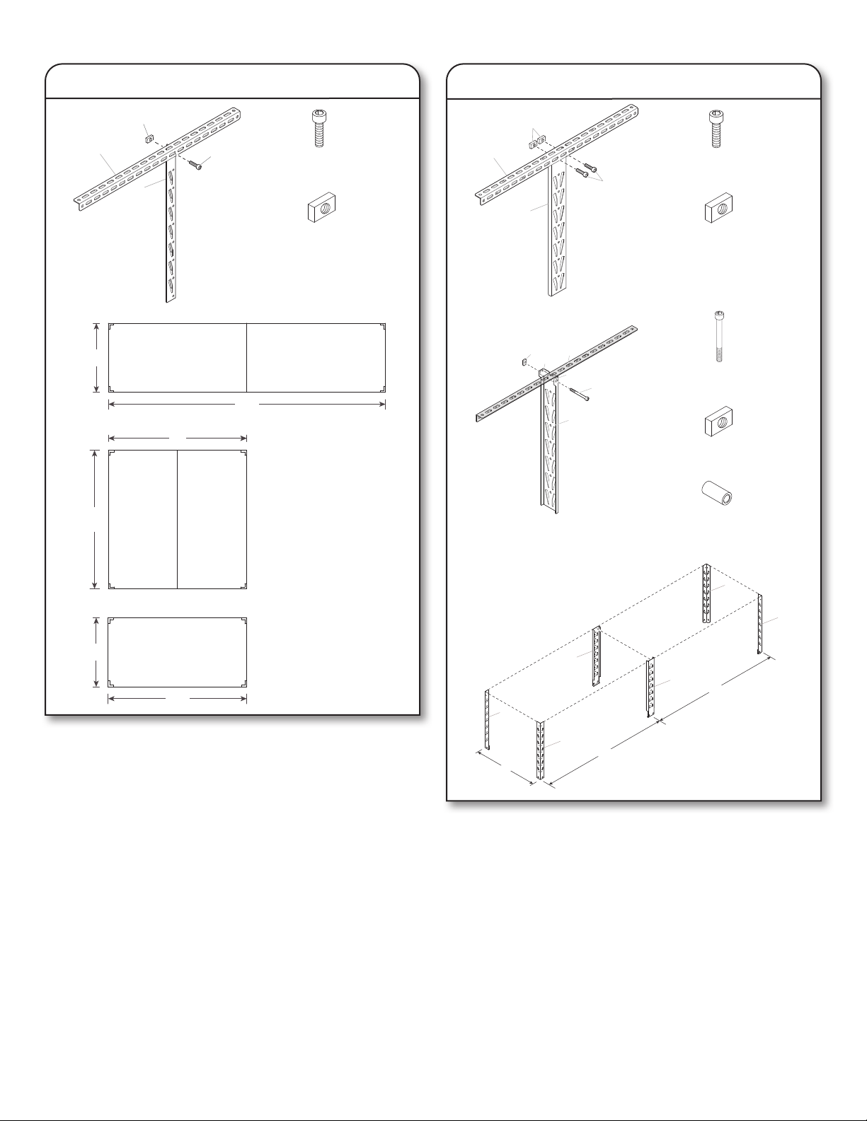
8.
Attach upper center supports (2' x 8')
F1
M8 - 1.25 x 12 Socket-head
cap screw
F4
M8 - 1.25 Rectangular nut
F6
F6
F4
P2
F3
P5
P2
F1
F4
P5
Parallel Mounting
Perpendicular Mounting
F3
M8 - 1.25 x 75 Socket-head
cap screw
F4
M8 - 1.25 Rectangular nut
F6
Spacer
P4
P4
P4
P4
P4
P4
24"
48"
48"
Attach the upper center supports (P5) to the ceiling brackets
using one of the methods detailed above, depending on ceiling
bracket mounting approach.
Parallel Mounting
Attach supports using M8 - 1.25 x 12 socket-head cap screws
(F1) (2) and M8 - 1.25 rectangular nuts (F4) (2) on each upper
center support.
Perpendicular Mounting
Attach supports using M8 - 1.25 x 75 socket-head cap screws
(F3), M8 - 1.25 rectangular nuts (F4) and spacer (F6) (2) on each
upper center support. Verify that all of the upper supports are
properly spaced. They should be on a 24"/48" pattern as shown
in the gure.
Attach the upper corner support (P3) to the ceiling brackets using
M8 - 1.25 x 12 (F1) (4) and M8 - 1.25 rectangular nuts (F4) (4).
Make sure they are positioned on the 24"/48" layout as required.
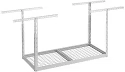
7. Attach upper corner supports
F1
M8 - 1.25 x 12 Socket-head
cap screw
P2
F4
F1
P3
F4
M8 - 1.25 Rectangular nut
96"
24"
48"
48"
48"
24"
2' x 8'
4' x 4'
2' x 4'
Loading ...
Loading ...
Loading ...