Loading ...
Loading ...
Loading ...
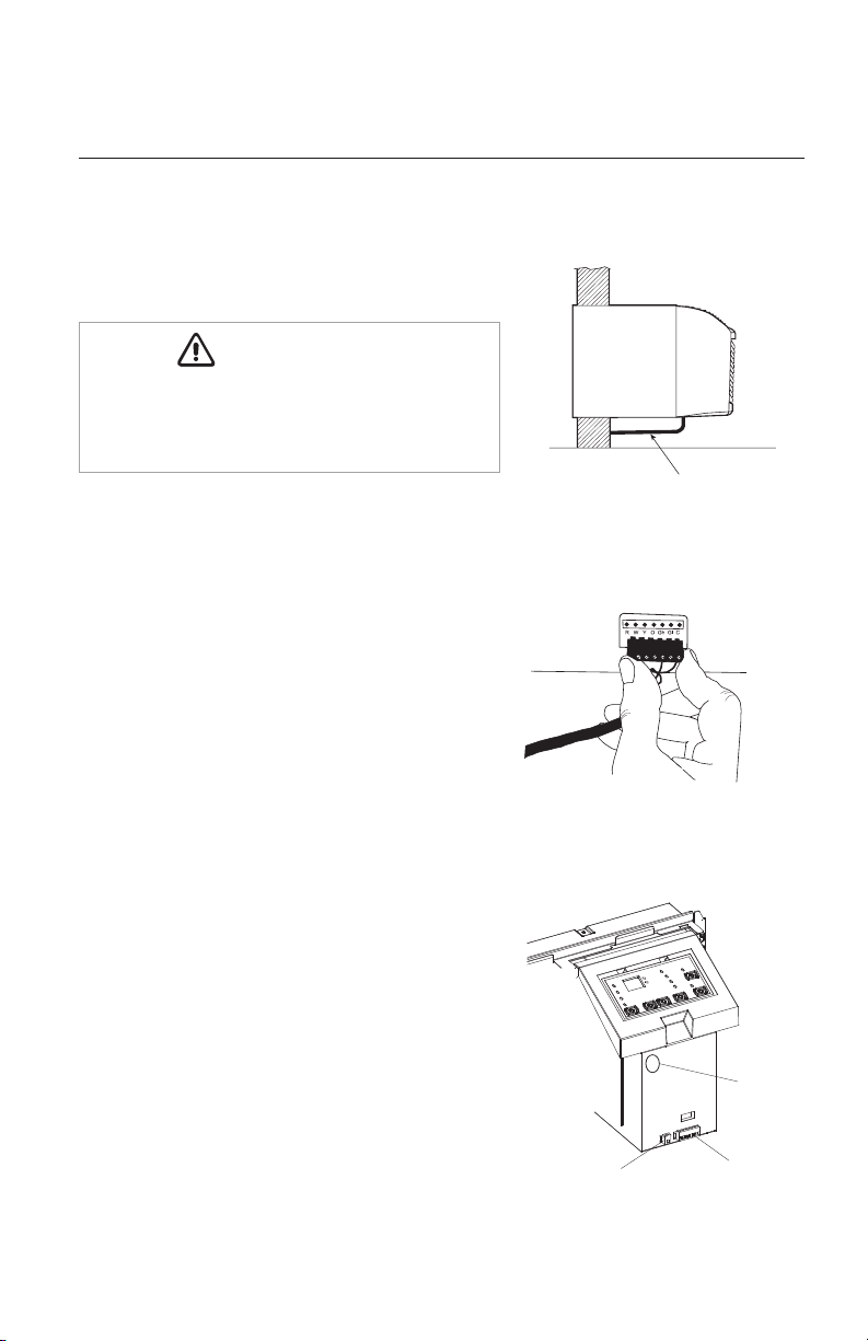
Thermostat Wire Routing
(under sleeve, behind front panel)
WALL THERMOSTAT INSTALLATION
ETAC II heat pump and heat/cool models will work with
most common 24vac single stage wall thermostats.
1. Disconnect all electrical power to unit including
disconnecting plug, fuses and circuit breakers.
2. Select a proper location on the wall for mounting
the wall thermostat
3. Install switch box (if required by code) and
thermostat back plate.
4. Install thermostat wire (field supplied) between
the thermostat and
ETAC II
. Unless otherwise
instructed, use standard 18-20AWG solid copper
thermostat wire.
5. Route thermostat wire beneath
ETAC II
unit and
up under the front panel on the power cord side
(see Fig. 19). Never route thermostat wire
through the wall sleeve.
6. Locate thermostat connection terminal on
control box (see Fig. 21). Carefully remove
terminal block from unit (see Fig. 20).
STATUS LED
Wall Thermostat
Terminal Connections
Energy Management
Terminal Connections
SYSTEM CONFIGURATION
Fig. 19 – Proper Wire Routing
Fig. 20 – Terminal Connector
Removal and Replacement
Thermostat Wire Routing
(under sleeve, behind front panel)
Fig. 21 – Terminal Connector
and Status LED Location
ELECTRICAL SHOCK HAZARD – The unit and
accessories should be installed and serviced only by
trained, qualified installers and service technicians.
WARNING
CAUTION
WARNING
CAUTION
18
Loading ...
Loading ...
Loading ...