Loading ...
Loading ...
Loading ...
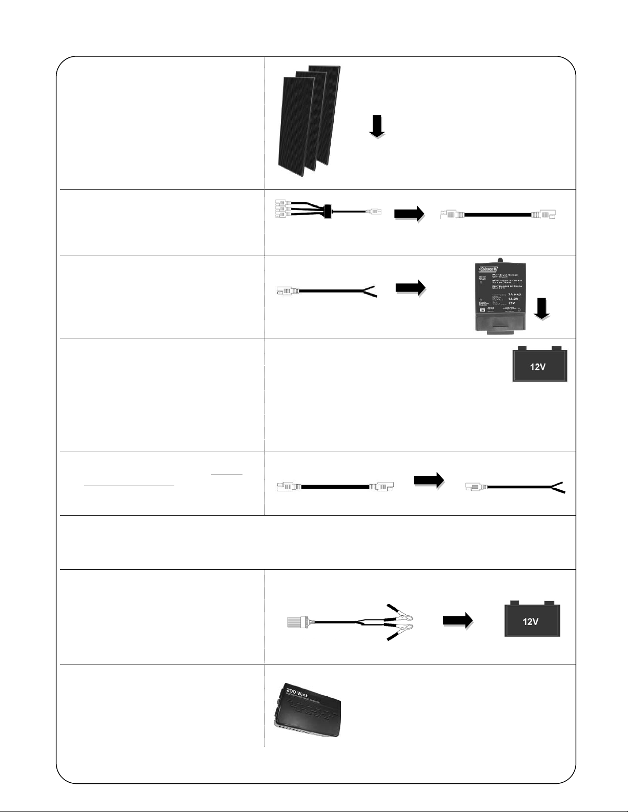
TYPICAL CONNECTION SETUP
1. Connect wires from panels to 3-in-1
connector.
(Part #1 > Part #7)
2. Connect the 3-in-1 connector to the
12’ Extension Cable.
(Part #7 > Part #3)
3. Splice charge controller connector and
charge controller.
(Positive to positive and negative to
negative)
(Part #8 > Part #2)
4. Connect charge controller to 12 Volt
battery (not included).
(Part #2 > 12Volt Battery)
OBSERVE POLARITY
Connect the charge controller battery positive (+) to the positive
(+) battery terminal. Then connect the charge controller battery
negative (-) post to the negative (-) battery terminal.
5. Connect the 12’ extension cable to the
charge controller connector to start
charging the battery.
(Part #3 > Part #8)
*Run your 12 Volt DC devices directly from the battery.
*For 110Volt-120Volt AC devices, use the power inverter (See steps below).
6. Connect power inverter connector to
the 12 Volt battery.
(Part #6 > 12Volt battery)
OBSERVE POLARITY. CONNECT
POSITIVE (RED) CLAMP FIRST.
7. Connect power inverter to the 12 Volt
socket on the power Inverter
connector.
(Part #9 > Part #6)
Note: It is strongly recommended to turn off the
inverter when not in use. The inverter's standby
current draw or no load draw is 0.2-0.3 Amps. If
the inverter is not turned off after use, it is
possible to drain an 18 Ahr battery within 3
days.
Part #1
Part #7
Part #8
Part #2
Part #3
Part #3
Part #8
Part #6
Part #9
Loading ...
Loading ...
Loading ...