Operator's Manual
I:RRFTSMRN+
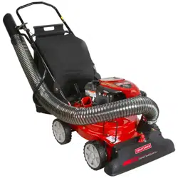
6.5 Horse Power
POWER PROPELLED YARD VACUUM
Model No. 247.770990
CAUTION: Before using
this product, read this
manual and follow all
safety rules and operating
instructions.
+ SAFETY
• ASSEMBLY
+ OPERATION
+ MAINTENANCE
+ PARTS LIST
ESPAI_OL
Sears, Roebuck and Co., Hoffman Estates, IL 60179, U.S.A.
Visit our web site: www.sears.com/craftsman
FORMNO.769-01281B
06/27/2006
WarrantyStatement..................................Page2
RepairProtectionAgreement...................Page3
SafeOperationPractices.........................Pages4-5
Assembly..................................................Pages6-9
Operation..................................................Pages10-13
Maintenance.............................................Pages14-15
ServiceAndAdjustment...........................Page16-19
Off-SeasonStorage..................................Page20
TroubleShooting......................................Page21
PartsList...................................................Page22-30
SafetyLabels............................................Page31
Espa_ol.....................................................Page33
ServiceNumbers......................................BackCover
OneYearFullWarranty on Craftsman YardVacuum
Thisequipmentis coveredbya one-yearwarranty,providedthat it is maintained,lubricated,andtunedupaccordingto the instructionsin the
operator'smanual.Duringthe warrantyyear,if this equipmentexperiencesany failuredueto defectsinmaterialor workmanship,RETURNITTO
YOURNEARESTSEARSPARTS& REPAIRCENTER,and Searswill repairit, freeof charge.In-homewarrantyserviceis available,butyou will
haveto paya trip charge.
This warranty does not cover:
• Expendableitemswhichbecomewornduring normaluse,such as spark plugs,air cleaners,belts,and oil filters.
• Tire replacementor repaircausedby puncturesfrom outsideobjects,such as nails, thorns,stumps,or glass.
• Repairsnecessarybecauseof operatorabuse,includingbut notlimitedto,damagecausedbyobjects,suchas stones,metaldebrisor
oversizedpiecesof wood, or impactingobjectsthatbendtheframeorcrankshaft,or over-speedingthe engine.
• Repairsnecessarybecauseof operatornegligence,includingbutnot limitedto, electricaland mechanicaldamagecausedby improper
storage,failureto usethe propergradeand amountof engine oil, or failureto maintainthe equipmentaccordingto the instructionscontained
in theoperator'smanual.
• Engine(fuelsystem)cleaningor repairscausedbyfuel determinedto be contaminatedor oxidized(stale). Ingeneral,fuel shouldbe used
within30 daysof itspurchasedate.
• Equipmentif usedfor commercialor rentalpurposes.
TO LOCATETHE NEARESTSEARSPARTS& REPAIRCENTEROR TO SCHEDULESERVICE,SIMPLYCONTACTSEARSAT 1-800-4-MY-
HOME®.
Thiswarrantygivesyouspecificlegalrightsandyou mayalso haveotherrightswhichmayvary fromstateto state.
SEARS, ROEBUCK AND CO., D/817WA, HOFFMAN ESTATES, IL 60179
Horse Power:
Engine Oil Type:
Engine Oil Capacity:
Fuel Capacity:
Spark Plug:
Spark Plug Gap:
6.5
SAE 30
18 ounces
1 1/2 Quarts
Champion® RJ19LM
.030"
Model Number .............................................................
Serial Number ..............................................................
Date of Purchase ..........................................................
Record the model number, serial number
and date of purchase above
Congratulationsonmakingasmartpurchase.YournewCraftsman®
productisdesignedandmanufacturedforyearsofdependableopera-
tion.Butlikeallproducts,itmayrequirerepairfromtimetotime.That's
whenhavingaRepairProtectionAgreementcansaveyoumoneyand
aggravation.
Here'swhat'sincludedintheAgreement:
,, Expertservicebyour12,000professionalrepairspecialists
,, Unlimitedserviceandnochargeforpartsandlaboronallcovered
repairs
,, Productreplacementifyourcoveredproductcan'tbefixed
,, Discountof10%fromregularpriceofserviceandservice-related
partsnotcoveredbytheagreement;also,10%offregularpriceof
preventivemaintenancecheck
,, Fasthelpbyphone- phonesupportfromaSearstechnicianon
productsrequiringin-homerepair,plusconvenientrepair
scheduling
PurchaseaRepairProtectionAgreementnowandprotectyourself
fromunexpectedhassleandexpense.
OnceyoupurchasetheAgreement,asimplephonecallisallthatit
takesforyoutoscheduleservice.Youcancallanytimedayornight,or
scheduleaserviceappointmentonline.
Searshasover12,000professionalrepairspecialists,whohave
accesstoover4.5millionqualitypartsandaccessories.That'sthe
kindofprofessionalismyoucancountontohelpprolongthelifeof
yournewpurchaseforyearstocome.PurchaseyourRepairProtection
Agreementtoday!
Somelimitationsand exclusionsapply. For pricesand additional
informationcall 1-800-827-6655.
Sears Installation Service
ForSearsprofessionalinstallationof homeappliances,garagedoor
openers,waterheaters,andothermajorhomeitems,in the U.S.A.call
1-800-4-MY-HOME®
WARNING: Engine Exhaust,some of its constituents,and certain vehicle components contain or emit
chemicals known to State of California to cause cancer and birth defects or other reproductiveharm.
DANGER: This machine was built to be operated according to the rules for safe operation in this manual. As with any type
of power equipment, carelessness or error on the part of the operator can result in serious injury. This machine is capable
of amputating hands and feet and throwing objects. Failureto observe the following safety instructionscould result in
serious injury or death.
WARNING: This symbol pointsout importantsafety instructionswhich, if not followed,couldendangerthe
personalsafety and/or property of yourselfand others. Readand follow all instructionsin this manual before
attemptingto operatethis machine. Failureto complywith these instructionsmay resultin personalinjury.
When you see this symbol.HEED ITS WARNING!
Preparation
1. Thoroughlyinspectthe areawheretile equipmentisto be used. Remove
all rocks,bottles,cans, orother foreignobjectswhichcould be pickedup
or thrownandcausepersonalinjuryor damageto the machine.
2. Alwayswearsafetyglassesor safetygoggles duringoperationor while
performingan adjustmentor repair,to protecteyes. Thrownobjectswhich
ricochetcan causeseriousinjuryto the eyes.
3. Wearsturdy, rough-soledwork shoesandclose-fittingslacksandshirts.
Loosefitting clothesorjewelry canbe caught in movableparts. Never
operatethis machinein barefeet or sandals.Wearleatherworkgloves
whenfeedingmaterialin the chipperchute.
4. Beforestarting,check all bolts andscrewsfor propertightnessto be sure
the machineis in safeworkingcondition.Also,visually inspectmachinefor
any damageat frequentintervals.
5. Maintainor replacesafetyand instructionslabels,as necessary.
6. To avoidpersonalinjury or propertydamageuse extremecare in handling
gasoline. Gasolineis extremelyflammableandthe vaporsareexplosive.
Seriouspersonalinjurycan occurwhen gasolineis spilled on yourself
or yourclotheswhichcan ignite.Washyour skin andchangeclothes
immediately.
a. Useonlyan approvedgasolinecontainer.
b. Extinguishall cigarettes,cigars,pipes,and othersourcesof ignition.
c. Neverfuel machineindoors.
d. Neverremovegascap or addfuel while the engineis hot or running.
e. Allowengine to cool at least two minutesbefore refueling.
f. Neveroverfill fuel tank. Filltank to no morethan 1/2 inch below bottom
of filler neckto providespacefor fuelexpansion.
g. Replacegasolinecap andtightensecurely.
h. If gasolineis spilled,wipeit offthe engineandequipment.Move
machineto anotherarea. Wait5 minutesbeforestartingthe engine.
i. Neverstore the machineorfuel containerinsidewherethere is an open
flame, spark,or pilot light (e.g.furnace, waterheater,spaceheater,
clothesdryer,etc.).
j. To reducea fire hazard,keep machinefree of grass, leaves,or other
debris build-up.Clean up oil orfuel spillageand removeany fuel
soakeddebris.
k. Allowmachineto cool at least 5 minutesbeforestoring.
Training
1. Read,understand,andfollowall instructionson the machineand in tile
manual(s)beforeattemptingto assemble andoperate.Keepthis manual
in a safeplace forfuture and regularreferenceand for orderingreplace-
ment parts.
2. Be familiarwith all controls andtheir proper operation.Know howto stop
the machineanddisengagethem quickly.
3. Neverallowchildren under 16years oldto operatethis machine.Children
16 yearsold and overshould readand understandthe operationinstruc-
tions andsafety rulesin this manualand shouldbetrainedand supervised
by a parent.
4. Neverallow adultsto operatethis machinewithout properinstruction.
5. Keepbystanders,helpers,pets,andchildren at least75 feet from the
machinewhile it is in operation.Stop machineif anyoneentersthe area.
6. Neverrunan engineindoorsor in a poorlyventilatedarea.Engineexhaust
containscarbonmonoxide,an odorlessand deadlygas.
7. Do not puthands andfeet near rotatingparts or in the feedingchambers
anddischargeopening.Contactwith the rotatingimpellercan amputate
fingers,hands,and feet.
8. Neverattempt to unclogeither the feed intakeor dischargeopening,
removeoremptyvacuumbag,or inspectand repairthe machinewhilethe
engine is running.Shutthe engineoff and waituntil all movingparts have
cometo a completestop. Disconnectthespark plugwire andground it
againstthe engine.
4
Operation
1. Do not puthands andfeet near rotatingparts or inthe feedingchambers
and dischargeopening.Contactwith the rotatingimpellercan amputate
fingers,hands,andfeet.
2. Beforestartingthe machine,makesurethe chipperchute,feed intake,and
cuttingchamberareempty andfree of all debris.
3. Thoroughlyinspectall materialto be shreddedand removeany metal,
rocks,bottles,cans,or otherforeignobjectswhichcould cause personal
injuryor damageto the machine.
4. If the impellerstrikesaforeign objector ifyour machineshouldstart
makingan unusualnoise or vibration,immediatelyshutthe engineoff.
Allowthe impellerto cometo a completestop. Disconnectthe spark plug
wire, groundit againstthe engineand performthe followingsteps:
a. Inspectfor damage.
b. Repairor replaceany damagedparts.
c. Checkfor anyloose parts andtighten to assure continuedsafe opera-
tion.
5. Do not allowan accumulationof processedmaterialto build up in the
dischargearea.This canpreventproperdischargeand resultin kickback
of materialthroughthefeed opening.
6. Do not attemptto shred or chip materiallargerthan specifiedon the
machineor inthis manual.Personalinjury or machinedamagecould
result.
7. Neverattemptto unclogeitherthe feed intakeor dischargeopeningwhile
theengine is running.Shuttheengine off, waituntil all movingpartshave
stopped,disconnectthe sparkplugwire andground it againstthe engine
beforeclearingdebris.
8. Neveroperatewithoutvacuumbag anddischargechuteproperlyattached
to the machine.Neveremptyor changevacuumbagwhile the engineis
running.Zipperedendof vacuum bagmustbe keptclosedat all times
duringoperation.
9. Neveroperatewithouteitherthe inlet nozzle or optional hoseattachment
properlyattachedto the machine.Neverattemptto attach or changeeither
attachmentwhilethe engineis running.
10.Keepall guards,deflectorsandsafetydevices in placeandoperating
properly.
11.Keepyour faceand bodyback andto the side of thechipperchute while
feedingmaterialinto the machineto avoidaccidentalkickbackinjuries.
12.Neveroperatethis machinewithoutgood visibilityor light. Alwaysbe sure
of yourfootingand keepa firm holdon the handles.
13.Do notoperatethis machineon a gravelsurface.
14.Do notoperatethis machinewhile underthe influenceof alcoholor drugs.
15.Mufflerand enginebecomehotand can causea burn. Donot touch.
16.Neverpickup or carry machinewhilethe engine is running.
Maintenance & Storage
1. Nevertamperwith safetydevices.Checktheir properoperationregularly.
2. Check bolts andscrewsfor proper tightnessat frequentintervalsto keep
the machinein safeworkingcondition.Also, visually inspectmachinefor
any damageand repair,if needed.
3. Beforecleaning,repairing,or inspecting,stopthe engine and makecertain
the impellerand all moving partshavestopped. Disconnectthespark plug
wire and groundit againstthe engineto preventunintendedstarting.
4. Donotchangethe engine governorsettingsoroverspeedthe engine.The
governorcontrolsthe maximumsafe operatingspeedof the engine.
5. Maintainor replacesafetyand instructionlabels,as necessary.
6. Followthis manualfor safeloading, unloading,transporting,andstorage
of this machine.
7. Neverstorethe machineorfuel containerinside wherethere is an open
flame, sparkor pilot light suchas a water heater,furnace,clothes dryer,
etc.
8. Alwaysreferto the operator'smanualfor properinstructionsonoff-season
storage.
9. Ifthe fuel tank hasto be drained,do this outdoors.
10.Observeproper disposallaws and regulationsfor gas, oil,etc. to protect
the environment.
Do not modify engine
Toavoidseriousinjuryor death,do notmodifyenginein anyway.Tampering
withthe governorsettingcanleadto a runawayengine andcauseit to operate
at unsafespeeds.Nevertamperwithfactorysettingof enginegovernor.
Your Responsibility
Restrictthe useof this powermachineto personswho read,understandand
followthe warningsandinstructionsinthis manualand on themachine.
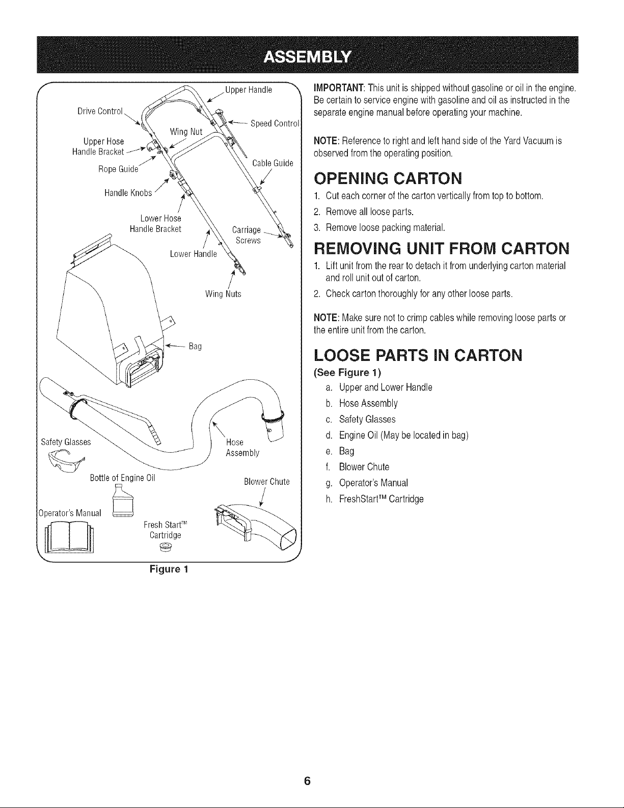
f _Upper Handle _'_ IMPORTANT:This unitis shippedwithoutgasolineor oil in the engine.
Becertainto serviceenginewith gasolineand oil as instructedin the
Drive Control.,,,,,,,_
Upper Hose
Handle
RopeGuidej/_
Lower Hose
HandleBracket
Wing Nut
SafetyGlasses
BottleofEngineOil
Lower Handle
Bag
Operator'sManual
FreshStartT_4
Cartridge
Figure 1
separateenginemanualbeforeoperatingyourmachine.
_eedControl
NOTE:Referenceto rightand left handside of the YardVacuumis
observedfromthe operatingposition.
CableGuide
S OPENING CARTON
1. Cuteach cornerof the cartonverticallyfromtop to bottom.
2. Removeall looseparts.
Carriage 3. Removeloosepackingmaterial.
Screws
REMOVING UNIT FROM CARTON
1. Lift unit fromthe rearto detachit fromunderlyingcarton material
and rollunitout of carton.
WingNuts 2. Checkcartonthoroughlyforany otherlooseparts.
NOTE:Makesure notto crimpcableswhile removingloosepartsor
the entireunit fromthecarton.
LOOSE PARTS iN CARTON
(See Figure 1)
a. Upperand LowerHandle
b. HoseAssembly
c. SafetyGlasses
d. EngineOil (May be locatedin bag)
Hose
Assembly e. Bag
f. BlowerChute
BIowerChute g. Operator'sManual
h. FreshStartTM Cartridge
6
f
Carriage Screw
Wing
Handle Bracke!.
Rope Guide
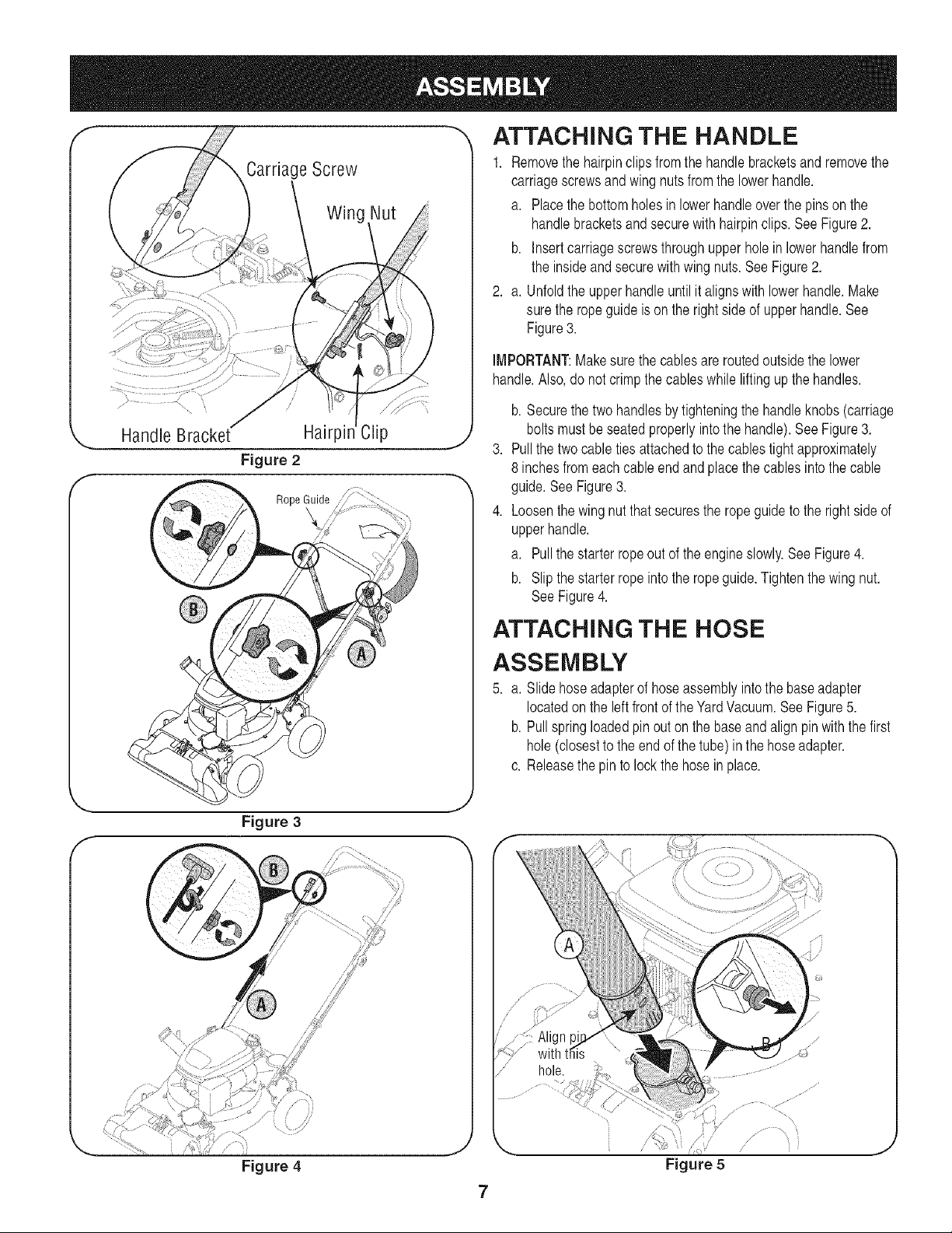
ATTACHING THE HANDLE
1. Removethehairpinclips fromthehandlebracketsand removethe
carriagescrewsandwingnuts fromthelowerhandle.
a. Placethe bottomholesin lowerhandleoverthe pins on the
handlebracketsandsecurewith hairpinclips. See Figure2.
b. Insertcarriagescrewsthroughupperhole in lowerhandlefrom
the insideandsecurewith wing nuts.See Figure2.
2. a. Unfoldthe upperhandleuntilit alignswithlowerhandle.Make
sure the ropeguideis on the rightsideof upperhandle.See
Figure3.
IMPORTANT:Makesurethe cablesare routedoutsidethe lower
handle.Also,do notcrimpthe cableswhile liftingup the handles.
b. Securethe twohandlesby tighteningthe handleknobs (carriage
boltsmustbe seatedproperlyintothe handle).See Figure3.
Pullthe twocableties attachedto the cablestight approximately
8 inchesfromeachcable end and placethe cablesintothe cable
guide.SeeFigure3.
Loosenthe wingnutthat securesthe ropeguideto the rightside of
upperhandle.
a. Pullthe starterrope outof the engineslowly.See Figure4.
b. Slipthe starterropeintothe ropeguide.Tightenthe wingnut.
SeeFigure4.
ATTACHING THE HOSE
ASSEMBLY
5. a. Slidehoseadapterof hoseassemblyintothe baseadapter
locatedon the leftfront of the YardVacuum.SeeFigure5.
b. Pullspringloadedpin outon the baseandalign pin with the first
hole (closestto the endof the tube) inthe hoseadapter.
c. Releasethe pinto lock the hose in place.
Figure 3
Figure 4
J
J
Figure 5
J
7
f-
Upper
Bracket
Lower
Hose
Handle
Bracket
Hose
Handle
Hose
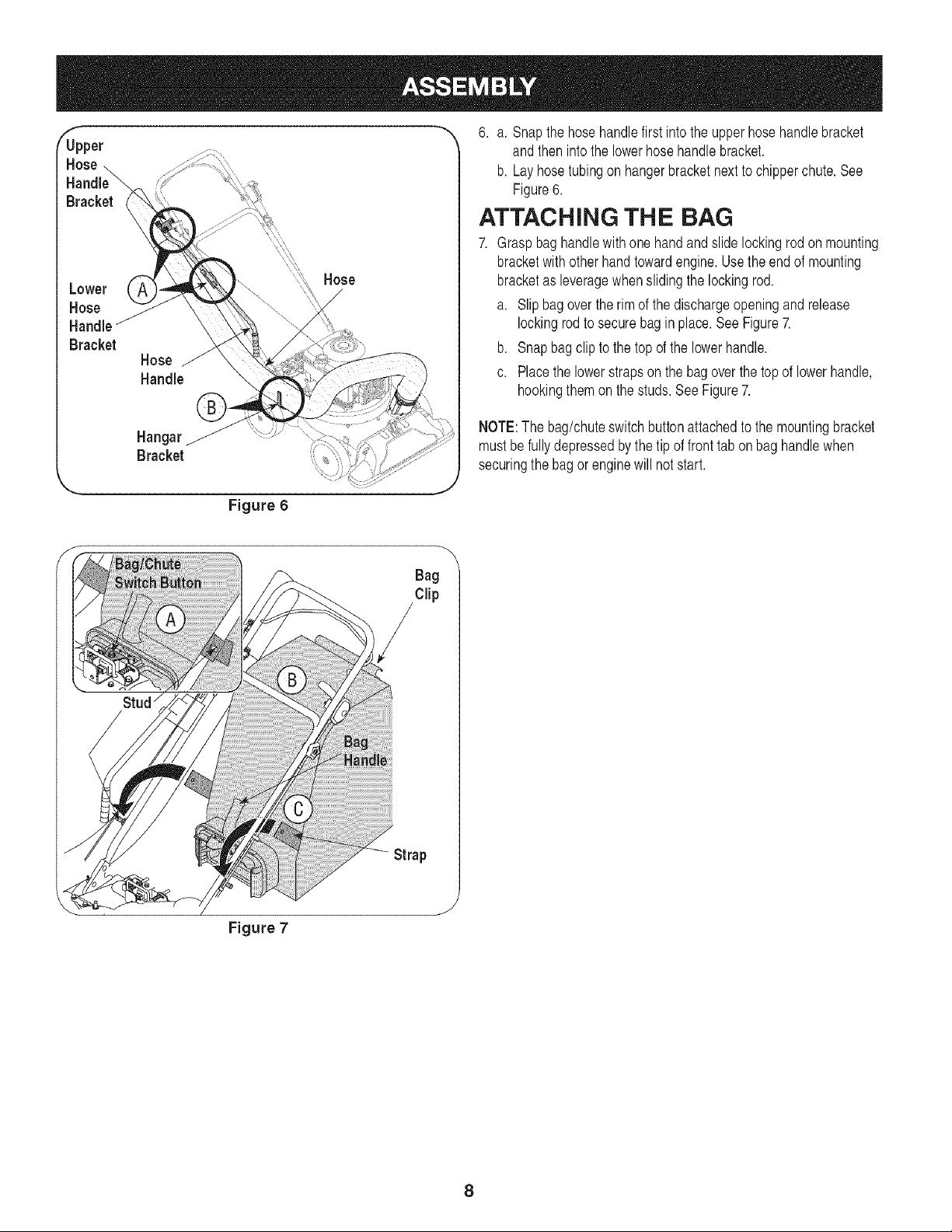
6. a. Snapthe hosehandlefirst intothe upperhosehandlebracket
andthen intothe lowerhosehandle bracket.
b. Layhosetubingon hangerbracketnextto chipperchute.See
Figure6.
ATTACHING THE BAG
7. Graspbaghandlewith one handand slide lockingrod on mounting
bracketwithotherhandtowardengine.Usethe end of mounting
bracketas leveragewhenslidingthe lockingrod.
a. Slipbag over therim of the dischargeopeningand release
lockingrodto securebag in place.See Figure7.
b. Snapbag clip to the topof the lowerhandle.
c. Placethe lowerstrapsonthe bag overthe topof lowerhandle,
hookingthemon the studs.See Figure7.
Hangar
Bracket
Figure 6
NOTE:The bag/chuteswitchbuttonattachedto the mountingbracket
mustbefully depressedby thetip of front tabon bag handlewhen
securingthe bagor enginewill not start.
\
Bag
Clip
Strap
Figure 7
8
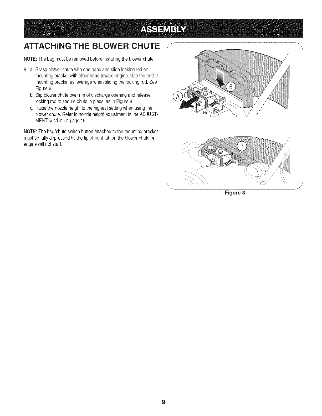
ATTACHING THE BLOWER CHUTE f
NOTE:The bagmustbe removedbeforeinstallingthe blowerchute.
8. a. Graspblowerchutewith one handand slide lockingrod on
mountingbracketwithother handtowardengine.Use the end of
mountingbracketas leveragewhenslidingthe lockingrod. See
Figure8.
b. Slipblowerchute overrim of dischargeopeningand release
lockingrodto secure chutein place,as in Figure8.
c. Raisethe nozzleheightto the highestsettingwhenusingthe
blowerchute.Referto nozzleheightadjustmentin the ADJUST-
MENTsectionon page 16.
NOTE:The bag/chuteswitchbuttonattachedto the mountingbracket
mustbefully depressedbythe tip of front tab on the blowerchuteor
enginewill notstart.
Figure 8
J
9
f
Drive Control
SpeedControl
Starter Handle
Bag Throttle Control Choke Control
Bag Handle
Fill
Hose
Handle
Chipl
Blower
Chute
\
NozzleHeig
Adjustment Lever
Fill
Hose
,,_Assembly
Nozzle/Hose
Nozzle
Figure 9
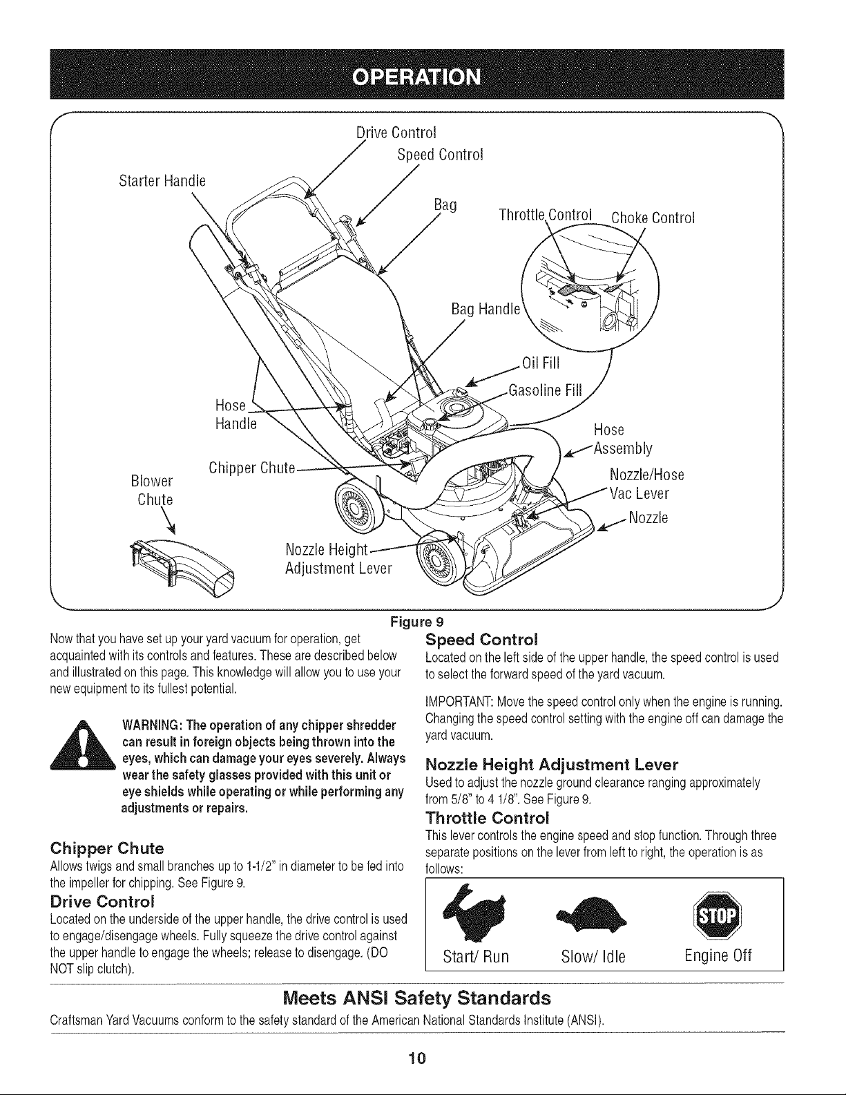
Nowthatyouhaveset up youryardvacuumfor operation,get
acquaintedwith its controlsand features.These are describedbelow
andillustratedon thispage.Thisknowledgewill allowyouto use your
newequipmentto its fullestpotential.
_ ARNING:The operation of any chippershredder
can result inforeign objects being thrown intothe
eyes,which candamage youreyesseverely. Always
wear the safety glasses providedwith this unit or
eyeshieldswhile operating or while performingany
adjustments orrepairs.
Chipper Chute
Allowstwigsandsmall branchesup to 1-1/2"indiameterto befed into
the impellerfor chipping.SeeFigure9.
Drive Control
Locatedon the undersideof the upperhandle,the drivecontrolis used
to engage/disengagewheels.Fullysqueezethe drivecontrolagainst
the upperhandleto engagethe wheels;releaseto disengage.(DO
NOTslip clutch).
Speed Control
Locatedonthe left sideof the upperhandle,the speedcontrolis used
to selectthe forwardspeedof the yardvacuum.
IMPORTANT:Movethespeedcontrolonly whenthe engineis running.
Changingthe speedcontrolsettingwith theengineoff can damagethe
yard vacuum.
Nozzle Height Adjustment Lever
Usedto adjustthe nozzlegroundclearancerangingapproximately
from5/8" to 4 1/8".SeeFigure9.
Throttle Control
This levercontrolsthe enginespeedand stop function.Throughthree
separatepositionson the leverfrom left to right, the operationis as
follows:
Start/Run Slow/Idle Engine Off
Meets ANSi Safety Standards
CraftsmanYardVacuumsconformto the safetystandardof theAmericanNationalStandardsInstitute(ANSI).
10
Choke Control
The chokecontrolis usedto choke thecarburetorand assist in starting
the engine.
Starter Handle
Usedto startthe engine.
Nozzle
Yardwastesuchas leavesor pine needlescan be vacuumedup
throughthe nozzlefor shredding.
Hose Assembly
Usedas an alternativeto the nozzleto vacuumyardwastesuch as
leavesorpine needlesin hard to reachplaces.See Figure9.
Nozzlel Hose Vac Lever
The nozzle/hosevac handleis locatedon top of the nozzle.Use it to
switchvacuumsuctionbetweenthe nozzleand the hoseassembly.
Hose Handle
Usedto guidehoseassemblywhenvacuuming.
Bag Handle
Usedto graspbag in order to assistin attaching,removing,and
emptyingbag.See Figure9.
Bag
Collectsshreddedmaterialfed throughthe chipperchute or vacuumed
throughthe nozzleor hose.
Blower Chute
When attachedto unit, the blowerchute is usedto dischargeyard
wastesuchas leaves,pineneedle,or small twigsacrossyard.
GAS AND OIL FILL=UP
Oil (one bottle shipped with unit)
First Time Use
1. Removeoil fill dipstick.
2. WiththeYardVacuumonlevelground,usea funnelto emptyentire
contentsof oil bottleprovidedintothe engine.
3. Replaceoil fill dipstickand tighten.
Subsequent Uses
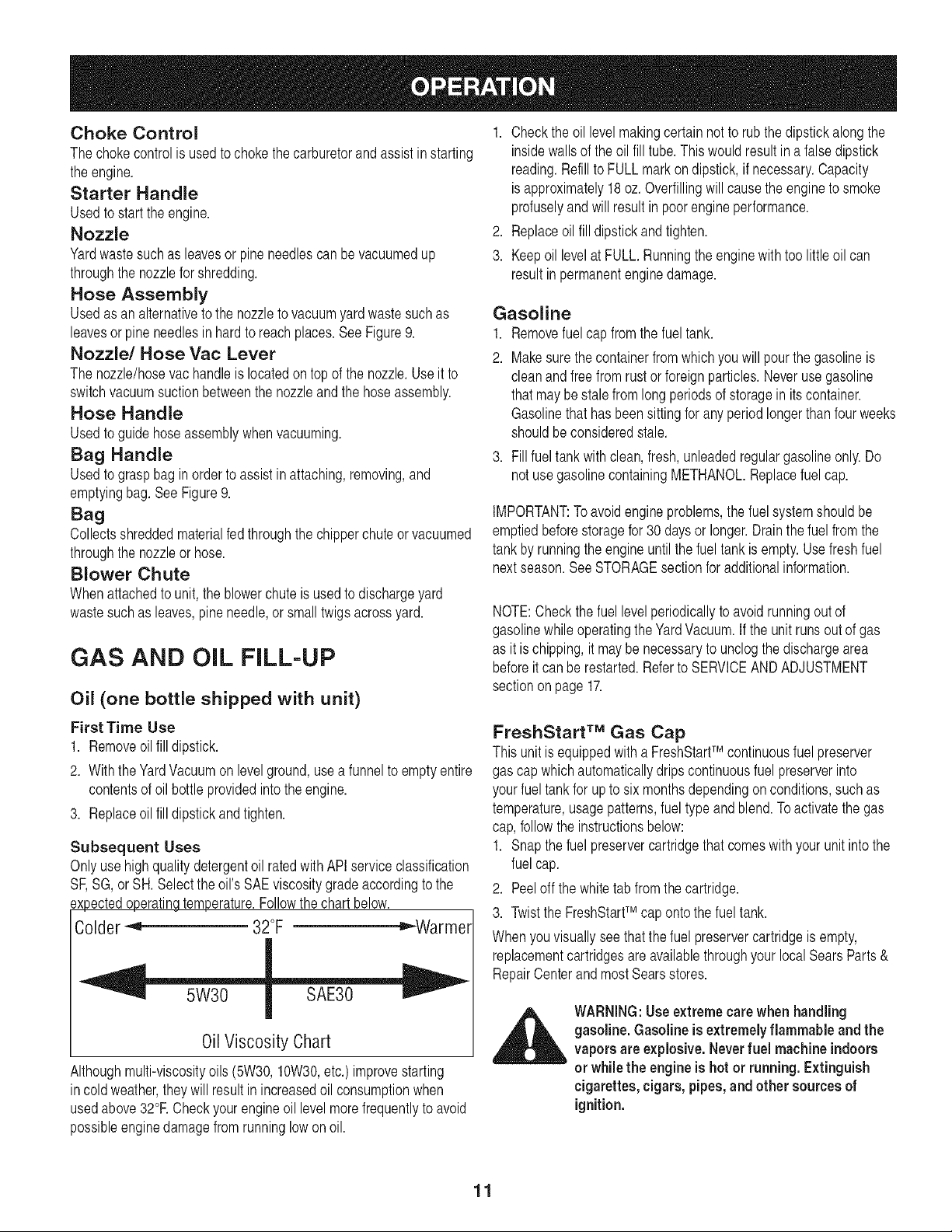
Onlyuse highqualitydetergentoil ratedwith APIserviceclassification
SE SG,or SH.Selectthe oil's SAEviscositygradeaccordingto the
axpectedoperatingtemperature.Followthe chart below.
Colder -_ 32°F _,,_Warmel
0il Viscosity Chart
Althoughmulti-viscosityoils (5W30,10W30,etc.)improvestarting
incold weather,they will result in increasedoil consumptionwhen
usedabove32°RCheckyourengineoil levelmorefrequentlyto avoid
possibleenginedamagefrom runninglowon oil.
1. Checkthe oil levelmakingcertainnotto rubthe dipstickalongthe
insidewalls of the oilfill tube.Thiswouldresultin a false dipstick
reading.Refillto FULL markon dipstick,if necessary.Capacity
isapproximately18oz.Overfillingwill causethe engineto smoke
profuselyand will result in poor engineperformance.
2. Replaceoil fill dipstickandtighten.
3. Keepoil levelat FULL.Runningthe enginewith too little oil can
resultin permanentenginedamage.
Gasoline
1. Removefuelcap from the fueltank.
2. Makesurethe containerfromwhichyou will pourthe gasolineis
cleanandfree from rust or foreignparticles.Neverusegasoline
that maybe stale from long periodsof storagein its container.
Gasolinethat hasbeen sittingfor anyperiod longerthanfourweeks
shouldbeconsideredstale.
3. Fillfuel tankwithclean,fresh,unleadedregulargasolineonly. Do
notusegasolinecontainingMETHANOL.Replacefuel cap.
IMPORTANT:Toavoidengineproblems,the fuelsystemshouldbe
emptiedbeforestoragefor30 daysor longer.Drainthe fuel fromthe
tankby runningthe engineuntil thefuel tank is empty.Use freshfuel
nextseason.SeeSTORAGEsectionfor additionalinformation.
NOTE:Checkthefuel levelperiodicallyto avoidrunningoutof
gasolinewhile operatingthe YardVacuum.If the unitrunsout of gas
as it is chipping,it maybenecessaryto unclogthe dischargearea
beforeit can be restarted.Referto SERVICEANDADJUSTMENT
sectionon page 17.
FreshStart TM Gas Cap
Thisunit is equippedwitha FreshStartTM continuousfuelpreserver
gas cap whichautomaticallydripscontinuousfuel preserverinto
yourfuel tankfor upto six monthsdependingon conditions,suchas
temperature,usagepatterns,fuel type and blend.Toactivatethe gas
cap,followthe instructionsbelow:
1. Snapthe fuelpreservercartridgethatcomeswith your unitinto the
fuel cap.
2. Peeloff thewhite tab fromthe cartridge.
3. Twistthe FreshStartTM caponto thefuel tank.
Whenyouvisuallysee thatthefuel preservercartridgeis empty,
replacementcartridgesare availablethroughyour localSearsParts &
RepairCenterand mostSearsstores.
_ WARNING:Useextremecarewhenhandling
gasoline. Gasoline is extremelyflammable and the
vapors are explosive.Neverfuel machine indoors
or while the engineis hot or running. Extinguish
cigarettes, cigars, pipes,and other sources of
ignition.
11
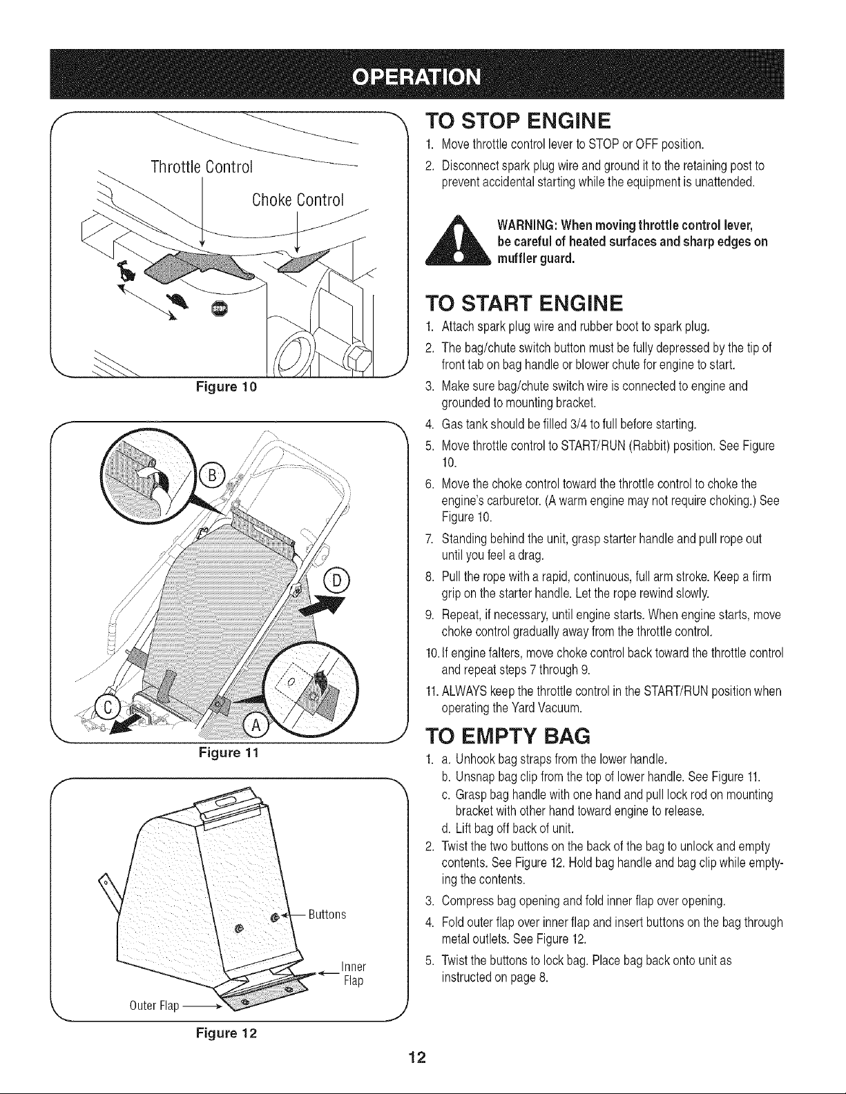
ThrottleControl
ChokeControl
TO STOP ENGINE
1. Movethrottlecontrolleverto STOPorOFFposition.
2. Disconnectspark plugwire and groundit to the retainingpost to
preventaccidentalstartingwhilethe equipmentis unattended.
_ ARNING:When movingthrottle controllever,
be careful of heatedsurfaces and sharp edgeson
muffler guard.
f
Figure 10
Figure 11
Figure 12
TO START ENGINE
1. Attachsparkplugwireandrubberboot to sparkplug.
2. The bag/chuteswitch buttonmustbe fully depressedbythe tip of
fronttab on bag handleor blowerchute for engineto start.
3. Makesurebag/chuteswitchwire is connectedto engineand
groundedto mountingbracket.
4. Gas tankshouldbe filled3/4 to fullbeforestarting.
5. Movethrottlecontrolto START/RUN(Rabbit)position.SeeFigure
10.
6. Movethechoke controltowardthethrottlecontrolto chokethe
engine'scarburetor.(Awarm enginemay notrequirechoking.)See
Figure10.
7. Standingbehindthe unit,graspstarterhandleand pull ropeout
until youfeel adrag.
8. Pullthe rope with a rapid,continuous,full arm stroke.Keepa firm
gripon the starterhandle.Letthe rope rewindslowly.
9. Repeat,if necessary,until enginestarts.When enginestarts,move
chokecontrolgraduallyawayfromthe throttlecontrol.
10.If enginefalters, movechoke controlback towardthe throttlecontrol
and repeatsteps7 through9.
11.ALWAYSkeepthe throttlecontrolin the START/RUNpositionwhen
operatingthe YardVacuum.
TO EMPTY BAG
1. a. Unhookbag strapsfrom the lowerhandle.
b. Unsnapbagclip fromthetop of lowerhandle.SeeFigure11.
c. Graspbaghandlewith one handand pull lock rod on mounting
bracketwith otherhandtowardengineto release.
d. Liftbagoff backof unit.
2. Twistthe twobuttonsonthe back of the bagto unlockand empty
contents.See Figure12.Hold baghandle and bag clipwhile empty-
ing thecontents.
3. Compressbagopeningand fold innerflap overopening.
4. Fold outerflapover innerflap andinsertbuttonson the bagthrough
metaloutlets.See Figure12.
5. Twistthe buttonsto lock bag.Placebag back ontounitas
instructedon page 8.
12
TO REMOVE BLOWER CHUTE
1. Graspblowerchute with one handand pull lock rod on mounting
bracketwith otherhand towardengine to release.Referto Figure7.
2. Removeblowerchutefrom overthe rim of the dischargeopening.
USING THE NOZZLE VACUUM
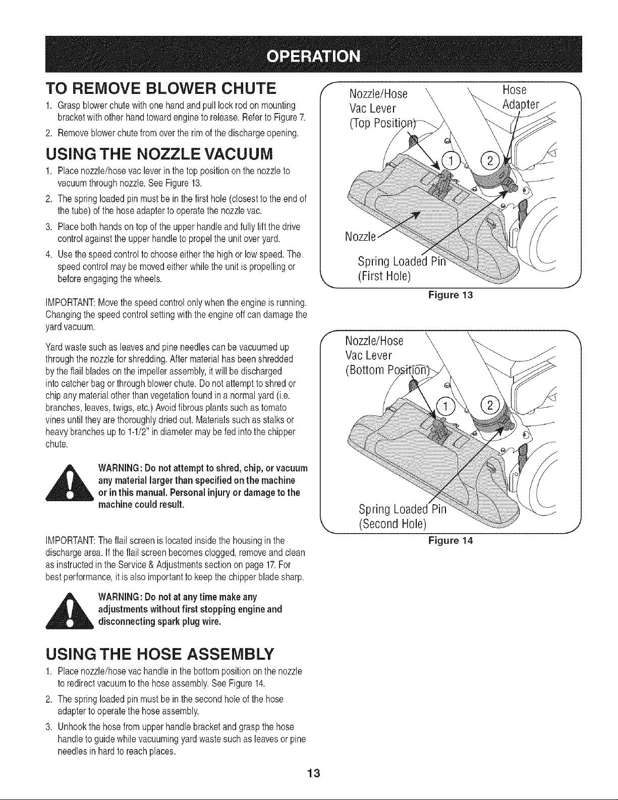
1. Placenozzle/hosevacleverin the top positionon the nozzleto
vacuumthroughnozzle.See Figure13.
2. Thespring loadedpinmustbe in the first hole (closestto the end of
the tube)of the hoseadapterto operatethe nozzlevac.
3. Placebothhandsontop of the upper handleand fully lift the drive
controlagainstthe upperhandleto propelthe unitoveryard.
4. Usethespeedcontrolto chooseeitherthe highor low speed.The
speedcontrolmaybe movedeitherwhilethe unit is propellingor
beforeengagingthe wheels.
IMPORTANT:Movethe speedcontrolonlywhenthe engine is running.
Changingthe speedcontrolsettingwith the engineoff candamagethe
yardvacuum.
Yardwastesuchas leavesandpine needlescan be vacuumedup
throughthe nozzlefor shredding.After materialhasbeenshredded
by theflail bladesonthe impellerassembly,it will bedischarged
intocatcherbagor throughblowerchute.Do notattemptto shredor
chipany materialother thanvegetationfoundin a normalyard (i.e.
branches,leaves,twigs,etc.) Avoidfibrousplants suchas tomato
vinesuntilthey are thoroughlydriedout. Materialssuchas stalksor
heavybranchesupto 1-1/2"indiametermay be fed intothe chipper
chute.
,_ WARNING:Do not attempt to shred, chip, or vacuum
any material largerthan specifiedon the machine
or inthis manual.Personalinjuryor damageto the
machine could result.
IMPORTANT:Theflail screenis locatedinsidethe housingin the
dischargearea.If the flailscreen becomesclogged,removeand clean
as instructedin the Service&Adjustmentssectionon page 17.For
bestperformance,it is alsoimportantto keepthe chipperbladesharp.
_ WARNING:Do not at anytime makeany
adjustments without first stopping engineand
disconnecting sparkplugwire.
f Nozzle/Hose Hose
VacLever
(Top Positi
Nozzle
Spring Loaded Pi
(First Hole)
Figure 13
J
f
Nozzle/Hose
Vac Lever
(Bottom Po
Spring Loaded Pin
(Second Hole)
Figure 14
J
USING THE HOSE ASSEMBLY
1. Placenozzle/hosevachandlein the bottompositionon the nozzle
to redirectvacuumto the hoseassembly.SeeFigure14.
2. Thespring loadedpinmustbe in the secondhole of the hose
adapterto operatethe hoseassembly.
3. Unhookthe hosefromupperhandlebracketand graspthe hose
handleto guidewhilevacuumingyardwastesuchas leavesor pine
needlesin hard to reachplaces.
13
©
Cleaner
Housing
\
Figure 15
GENERAL RECOMMENDATIONS
1. Alwaysobservesafetyruleswhen performing
anymaintenance.
2. Thewarrantyon thisyardvacuumdoes notcover itemsthathave
beensubjectedto operatorabuseor negligence.To receivefull
valuefromwarranty,operatormustmaintainthe equipmentas
instructedhere.
3. Someadjustmentswill haveto be madeperiodicallyto maintain
yourunit properly.
4. Periodicallycheckall fastenersand makesuretheseare tight.
,_ WARNING:Alwaysstopengineand disconnect
sparkplugwire before performingany maintenance
or adjustments. Alwayswear safetyglasses during
operation or while performingany adjustments or
repairs.
LUBRICATION
1. Wheels-Placea few dropsof SAE30 oil on eachshoulderscrew
oncea season.Referto Figure23 on page 18.
2. Nozzle height adjustment levers- Lubricatenozzleheightadjust-
mentleverswith lightoil. Referto Figure9.
3. Locking Rod- Lubricatethe lockrod and compressionsprings
whichattachto the mountingbracket.Referto Figure8.
CLEAN EQUIPMENT
1. Cleanthe YardVacuumthoroughlyaftereachuse.
2. Washbag periodicallywith water.Allowto dry thoroughlyin shade.
3. If the flail screenbecomesclogged,removeand cleanas instructed
in the SERVICEAND ADJUSTMENTSsection.
NOTE:Cleaningwith a forcefulspray of wateris not recommendedas
it couldcontaminatethe fuelsystem.
CHECK ENGINE OIL
1. Stopengineandwaitseveralminutesbeforecheckingoil level.
Withengineon levelground,the oil mustbe to FULL markon
dipstick.
2. Removeoil fill dipstick.
3. Checkoil levelondipstick.Levelshouldbe at FULLmark.(If not,
see "SubsequentUses"on page 11).
4. Replaceoilfill dipstickand tighten.
CHANGE ENGINE OIL
,, Only use highqualitydetergentoil ratedwith API serviceclassifica-
tion SF,SG, orSH.Selecttheoil's SAEviscositygradeaccording
to the expectedoperatingtemperature.Referto operationsection
for viscositychart.
Changeengineoilafter the firstfive hoursof operation,and every
twenty-fivehoursthereafter.
TO DRAIN OIL
Drainoil whileengineiswarm.Followthe instructionsgivenbelow:
1. Drainthe fuel fromthe tankby runningthe engineuntilthe fuel tank
is empty.
2. Removeoil fill dipstick.
3. Tip unit onits sideto drainthroughthe oil fill tube.
4. Whenengineis drainedof all oil, refillwithapproximately18oz. of
freshoil. Referto Gas And Oil Fill-Up in OPERATIONsection.
5. Replaceoilfill dipstickand tighten.
SERVICE AIR CLEANER
The aircleanerpreventsdamagingdirt, dust, etc.,from enteringthe
carburetorand beingforcedinto theengineand is importantto engine
lifeandperformance.The air cleanerconsistsof a pleatedfilter.Never
runthe enginewithoutanair cleanercompletelyassembled.
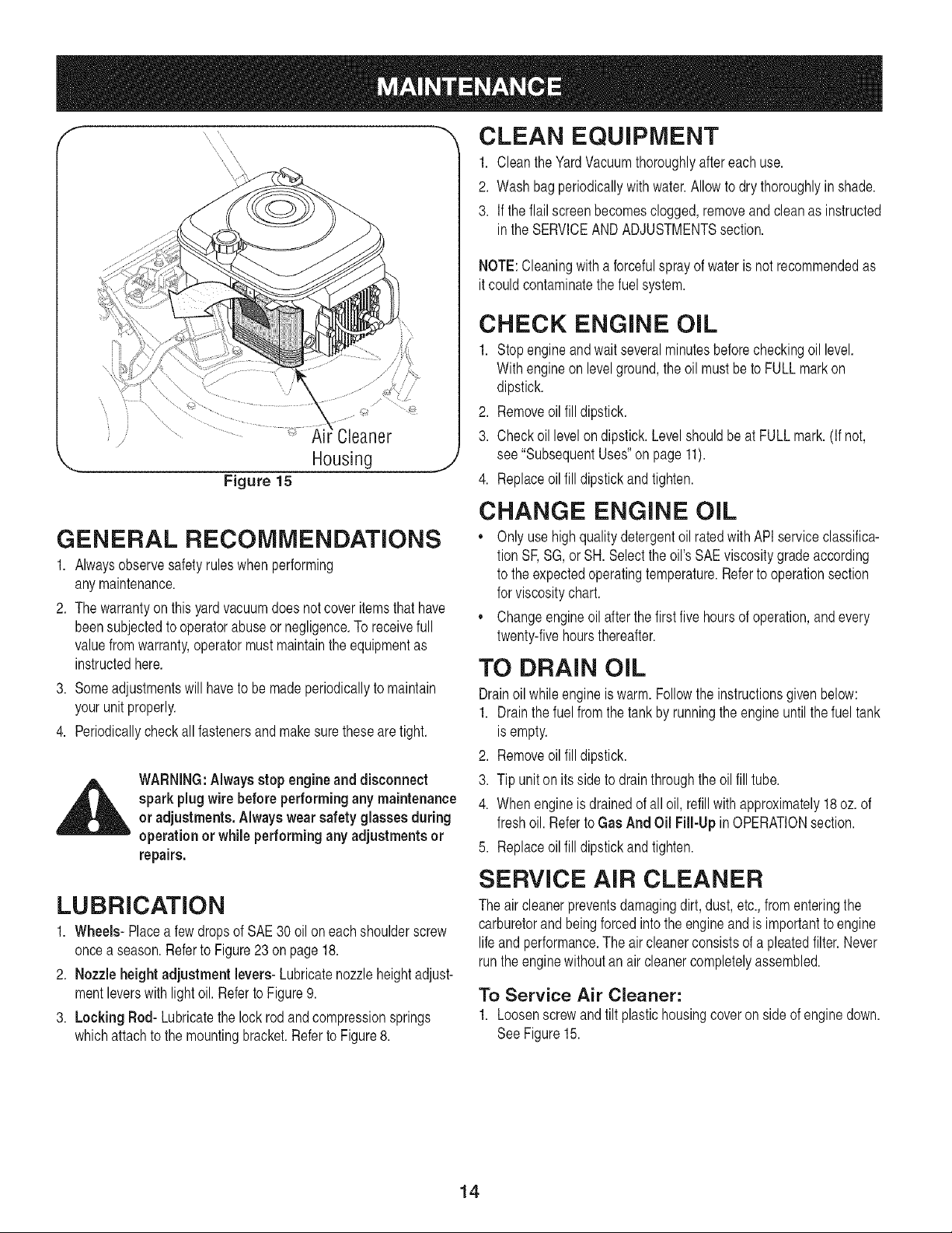
To Service Air Cleaner:
1. Loosenscrewand tiltplastichousingcoveron side ofenginedown.
SeeFigure15.
14
2. Removepleatedfilter from plastichousingcoverand replacewith
cleanor newfilter.
3. Tiltcoverupinto placeand tightenscrew.
NOTE:If thefilter istorn or damagedinanyway,replaceit.
_ ARNING:Temperatureof muffler and nearbyareas
mayexceed 150° F (65°C). Avoidthese areas.
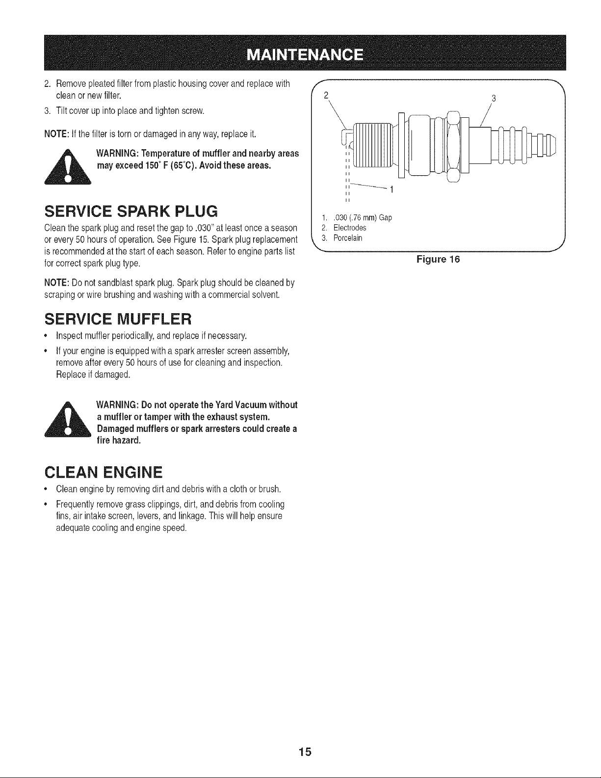
SERVICE SPARK PLUG
Cleanthesparkplug and resetthe gap to .030"at least oncea season
or every50hoursof operation.See Figure15.Sparkplug replacement
is recommendedat the start of eachseason.Referto engineparts list
for correctsparkplug type.
NOTE:Do notsandblastspark plug.Sparkplug shouldbe cleanedby
scrapingor wire brushingand washingwith a commercialsolvent.
f --,,
2 3
II
II
II
II
II
II
1..030 (.76 turn) Gap
2. Electrodes
3. Porcelain
Figure 16
,J
SERVICE MUFFLER
• Inspectmufflerperiodically,and replaceif necessary.
• If yourengineis equippedwith a spark arresterscreenassembly,
removeafterevery 50 hoursof use for cleaningand inspection.
Replaceif damaged.
_ ARNING:Donot operate the YardVacuumwithout
a muffler ortamper withthe exhaustsystem.
Damagedmufflers or spark arresters could create a
fire hazard.
CLEAN ENGINE
• Cleanengineby removingdirt and debriswith a cloth or brush.
Frequentlyremovegrass clippings,dirt, and debrisfrom cooling
fins,air intakescreen,levers,and linkage.This will help ensure
adequatecoolingand enginespeed.
15
NozzleHeight
Adjustment
_ WARNING: Donot at any time makeany adjustment
to the unit withoutfirst stoppingengineand discon-
nectingsparkplug wire.
Nozzle
Figure 17
f_A Drive Control
J
/
/
\\
XX
X
Drive Control
Z-Fittin_
Front Hole
Rear Hole Drive Control Cable
J
Figure 18
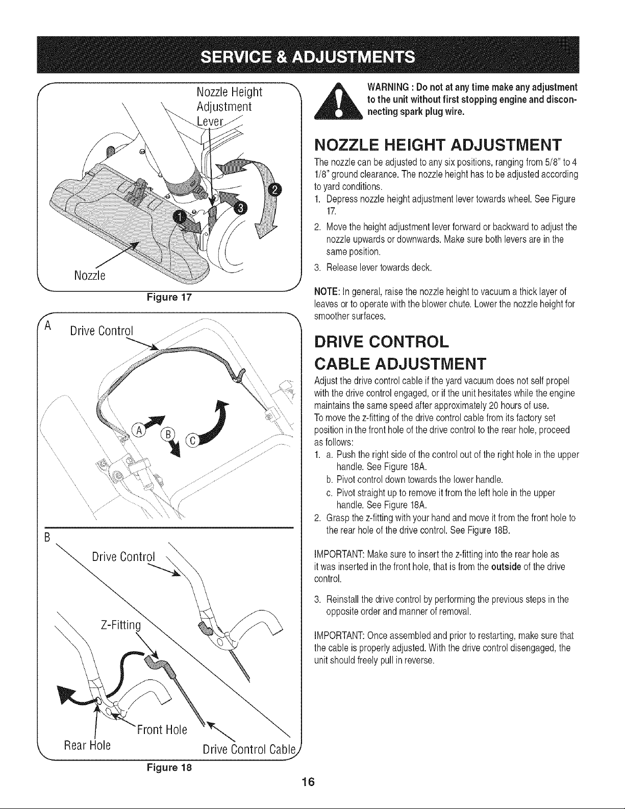
NOZZLE HEIGHT ADJUSTMENT
The nozzlecan beadjustedtoany six positions,rangingfrom5/8" to4
1/8"groundclearance.The nozzleheighthastobeadjustedaccording
toyard conditions.
1. Depressnozzleheightadjustmentlevertowardswheel.See Figure
17.
2. Movethe heightadjustmentleverforwardor backwardto adjustthe
nozzleupwardsor downwards.Makesureboth leversare in the
sameposition.
3. Releaselevertowardsdeck.
NOTE:In general,raisethe nozzleheightto vacuuma thick layerof
leavesor to operatewith the blowerchute.Lowerthe nozzleheightfor
smoothersurfaces.
DRIVE CONTROL
CABLE ADJUSTMENT
Adjustthedrivecontrolcable iftheyardvacuumdoes notself propel
withthedrivecontrolengaged,or iftheunit hesitateswhiletheengine
maintainsthesamespeedafter approximately20 hoursof use.
To movethez-fittingof thedrive controlcablefrom itsfactory set
positioninthefronthole ofthedrivecontrolto therear hole,proceed
as follows:
1. a. Pushtheright sideof thecontrolout of theright holein theupper
handle.See Figure18A.
b. Pivotcontroldowntowardsthe lowerhandle.
c. Pivotstraightup to removeit from theleft hole in the upper
handle.See Figure18A.
2. Graspthe z-fittingwithyourhand and moveit from the front hole to
the rearholeof the drivecontrol.SeeFigure18B.
IMPORTANT:Makesureto insert the z-fittingintothe rear hole as
it wasinsertedinthe fronthole,that is from the outside of thedrive
control.
3. Reinstallthe drivecontrol byperformingthe previoussteps in the
oppositeorderand mannerof removal.
IMPORTANT:Onceassembledand prior to restarting,makesure that
the cable is properlyadjusted.With the drivecontroldisengaged,the
unitshouldfreelypullin reverse.
16
CARBURETOR ADJUSTMENT
_ ARNING:if any adjustments (e.g. carburetor)are
made to the enginewhilethe engineis running,
keepclearof all moving parts. Becarefulof heated
surfacesand muffler.
The carburetorhas beenpre-setat thefactory and shouldnot require
adjustment.If yourenginedoes notoperateproperlydueto suspected
carburetorproblems,take yourYardVacuumto a SearsParts & Repair
Centerfor repairandadjustment.
ENGINE SPEED
The enginespeedon yourYardVacuumhas beenset at thefactory.
Do notattemptto increasethe engineRPM.Ifyou thinkthat theengine
is runningtoo fastor too slow,takeyourYardVacuumto thenearest
SearsParts& RepairCenter for repairand adjustment.
,i_i WARNING:Do not attempt to alter the enginespeed
by tampering withthe engine'sgovernorlinkage.
Doing so couldresult in serious personalinjuryand
damage to the engine.The engineRPM has been set
at the factory.
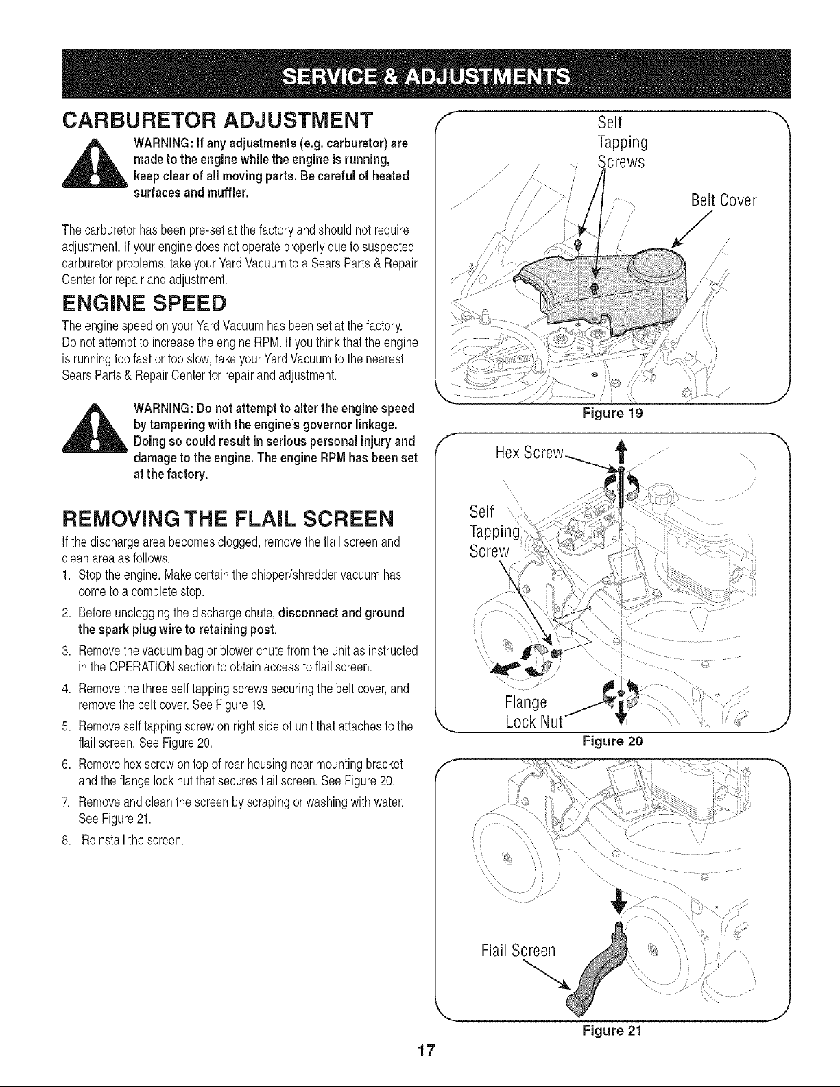
REMOVING THE FLAIL SCREEN
If thedischargeareabecomesclogged,removetheflail screenand
cleanareaas follows.
1. Stopthe engine.Makecertainthe chipper/shreddervacuumhas
cometo a completestop.
2. Beforeuncloggingthe dischargechute,disconnect and ground
the spark plug wire to retaining post.
3. Removethevacuumbag or blowerchute from the unitas instructed
inthe OPERATIONsectionto obtainaccessto flail screen.
4. Removethethreeself tappingscrewssecuringthe belt cover,and
removethe belt cover.See Figure19.
5. Removeself tappingscrewon rightsideof unitthat attachesto the
flail screen.See Figure20.
6. Removehexscrewon top of rear housingnear mountingbracket
andthe flangelock nutthat securesflailscreen.See Figure20.
7. Removeandclean thescreen by scrapingor washingwith water.
SeeFigure21.
8. Reinstallthe screen.
17
//
/
//
/-
Self
Tapping
crews
: .... Belt Cover
/ S
/
/
/
i /
/<
/
f
Figure 19
/
Screw
\
f
Flange
Lock Nut
J
Flail Screen
Figure 21
J
Hex Cap ............ "
, Screws
f
............."_FrontSupport Braceand Lock NUi ....
J
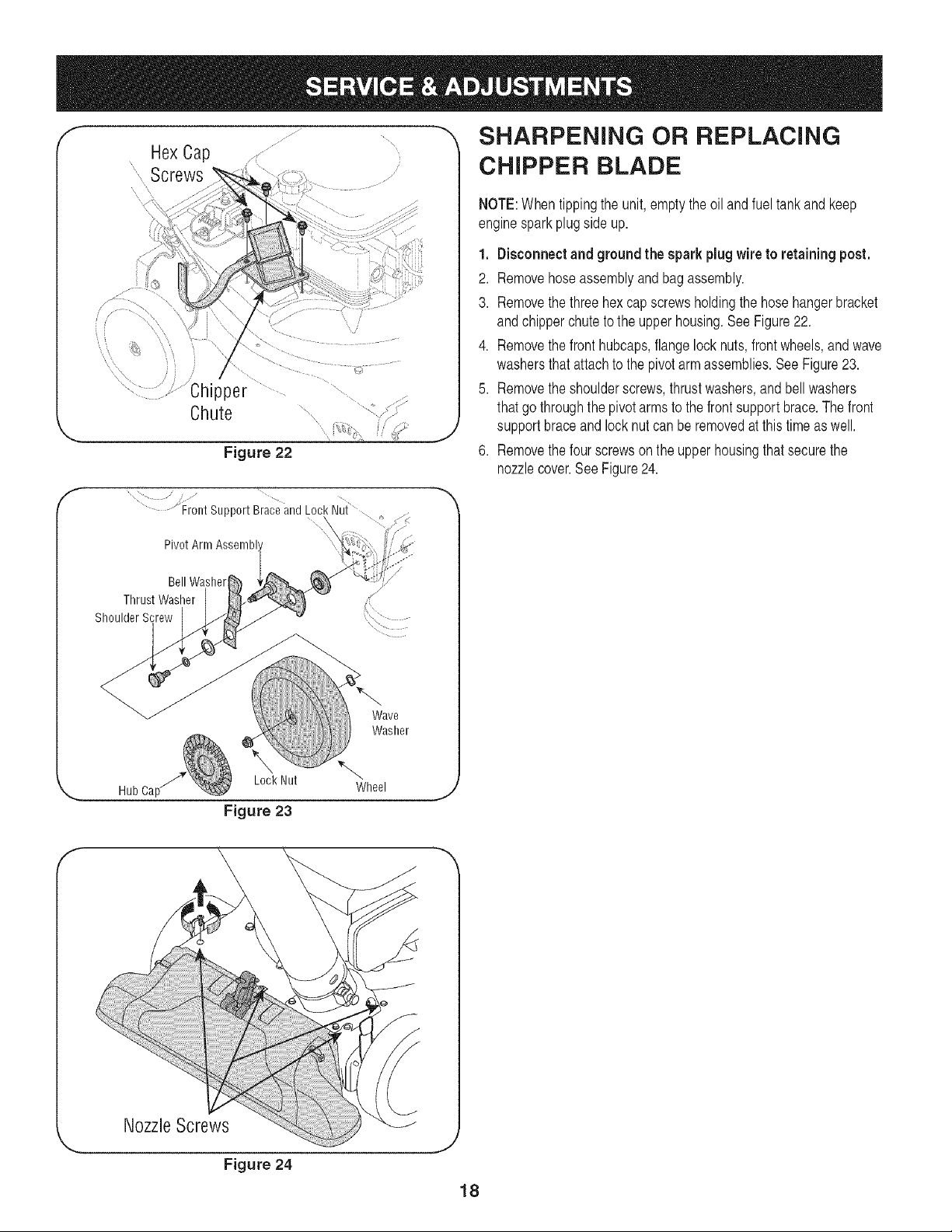
SHARPENING OR REPLACING
CHIPPER BLADE
NOTE:Whentippingthe unit, emptythe oil and fuel tankand keep
enginesparkplug side up.
1. Disconnect and ground the spark plugwire to retaining post.
2. Removehoseassemblyand bag assembly.
3. Removethe threehexcap screwsholdingthe hosehangerbracket
andchipperchuteto the upper housing.See Figure22.
4. Removethe front hubcaps,flangelock nuts,frontwheels,and wave
washersthat attachto the pivotarmassemblies.See Figure23.
5. Removethe shoulderscrews,thrustwashers,and bellwashers
thatgo throughthe pivotarms to the front supportbrace.The front
supportbraceand lock nutcan be removedat this time as well.
6. Removethe fourscrewson the upperhousingthat securethe
nozzlecover.SeeFigure24.
Pivot Arm
Bell Washer
Thrust Washer
Shoulder Screw
%_*.r
Wave
Washer
Hub Ca[
LockNut
Figure 23
Wheel
,J
f
Nozzle Screws
Figure 24
,J
18
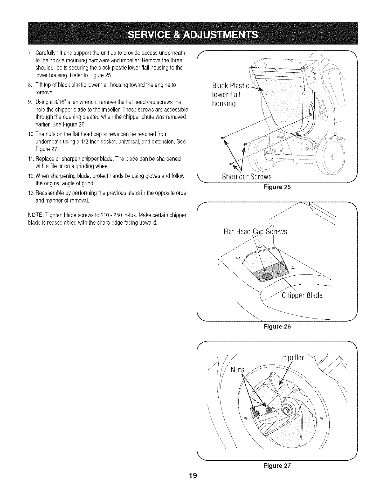
7. Carefullytilt and supportthe unitup to provideaccessunderneath
to the nozzlemountinghardwareand impeller.Removethe three
shoulderbolts securingthe black plasticlowerflail housingto the
lowerhousing.Referto Figure25.
8. Tilttop of blackplasticlowerflailhousingtowardthe engineto
remove.
9. Usinga 3/16"allenwrench,removethe flatheadcapscrewsthat
holdthechipperblade to the impeller.These screwsare accessible
throughthe openingcreatedwhenthe chipperchutewas removed
earlier.See Figure26.
lO.The nutson theflat headcap screwscan be reachedfrom
underneathusinga 1/2-inchsocket,universal,andextension.See
Figure27.
11.Replaceor sharpenchipperblade.The bladecan be sharpened
withafile or on a grindingwheel.
12.Whensharpeningblade,protecthandsby usingglovesand follow
the originalangleof grind.
13.Reassembleby performingthe previousstepsin theoppositeorder
andmannerof removal.
NOTE:Tighten bladescrewsto 210- 250 in-lbs.Makecertain chipper
bladeis reassembledwith the sharpedge facingupward.
f --,,
Black Plastic
lower flail
housing
.............. ,
Shoulder Screws
Figure 25
J
f
Flat Head Screws
Chipper Blade
f
_NNuts
Figure 26
Impeller
\
19
Figure 27
J
PrepareyourCraftsmanYardVacuumfor storageat the end of the
seasonor if the unitwill not beusedfor 30 daysor longer.A yearly
check-upbyyour localSearsParts & RepairCenteris a good wayto
ensurethat the unit runsproperlynextseason.
Yard Vacuum
,, Cleantheequipmentthoroughly.
,, Wipeequipmentwithan oiled rag to preventrust. Usea light oil or
siliconeto wipe.
,, Servicethe enginefollowinginstructionsbelow.
,, Storeunit ina clean,dry area.Do not storenextto corrosive
materialssuchas fertilizer.
Engine
IMPORTANT:It is importantto preventgumdepositsfrom formingin
essentialfuelsystempartssuch as the carburetor,fuelfilter,fuel hose,
ortankduringstorage.Also, alcoholblendedfuels (calledgasoholor
usingethanolor methanol)can attractmoisturewhich leadsto separa-
tionandformationof acids duringstorage.Acidic gascan damagethe
fuelsystemof anenginewhile in storage.
NOTE:Fuelstabilizeris anacceptablealternativeto emptyingthe tank
of fuel inminimizingthe formationof fuel gumdepositsduringstorage.
,, Addstabilizerto gasolineinfuel tank(if FreshStartTM fuel preserver
cartridgeis empty)orstoragecontainer.
,, Do not drainthe gas tankand carburetorif usingfuel stabilizer.
Inall cases,drainall the oil fromthe crankcase(thisshouldbedone
afterthe enginehas beenoperatedand is still warm)and refillthe
crankcasewithfresh oil.
Whenyou visuallyseethat thefuel preservercartridge isempty,
replacementcartridgesare availablethroughyour localSearsParts &
RepairCenterand mostSearsstores.
Ifyou donot use FreshStartTM or otherfuelstabilizer,followthese
instructions:
,, Drainthe fuel fromthe tankby runningthe engineuntilthe fuel tank
is empty.
,, Removespark plug,pourapproximately1/2 ounce(approximately
onetablespoon)of engineoil into cylinderand crankslowlyto
distributeoil.
,, Replacesparkplug.
Other
,, Do not storegasolinefromoneseasonto another.
,, Replacethe gasolinecan if it starts to rust.Rustand/ordirt in the
gasolinewillcauseproblems.
,, Store unitin a clean, dry area.Do notstorenext to corrosive
materials,suchas fertilizer.
NOTE:If storingin an unventilatedor metalstorageshed,be certainto
rustproofthe equipmentby coatingwith a lightoil or silicone.
2O
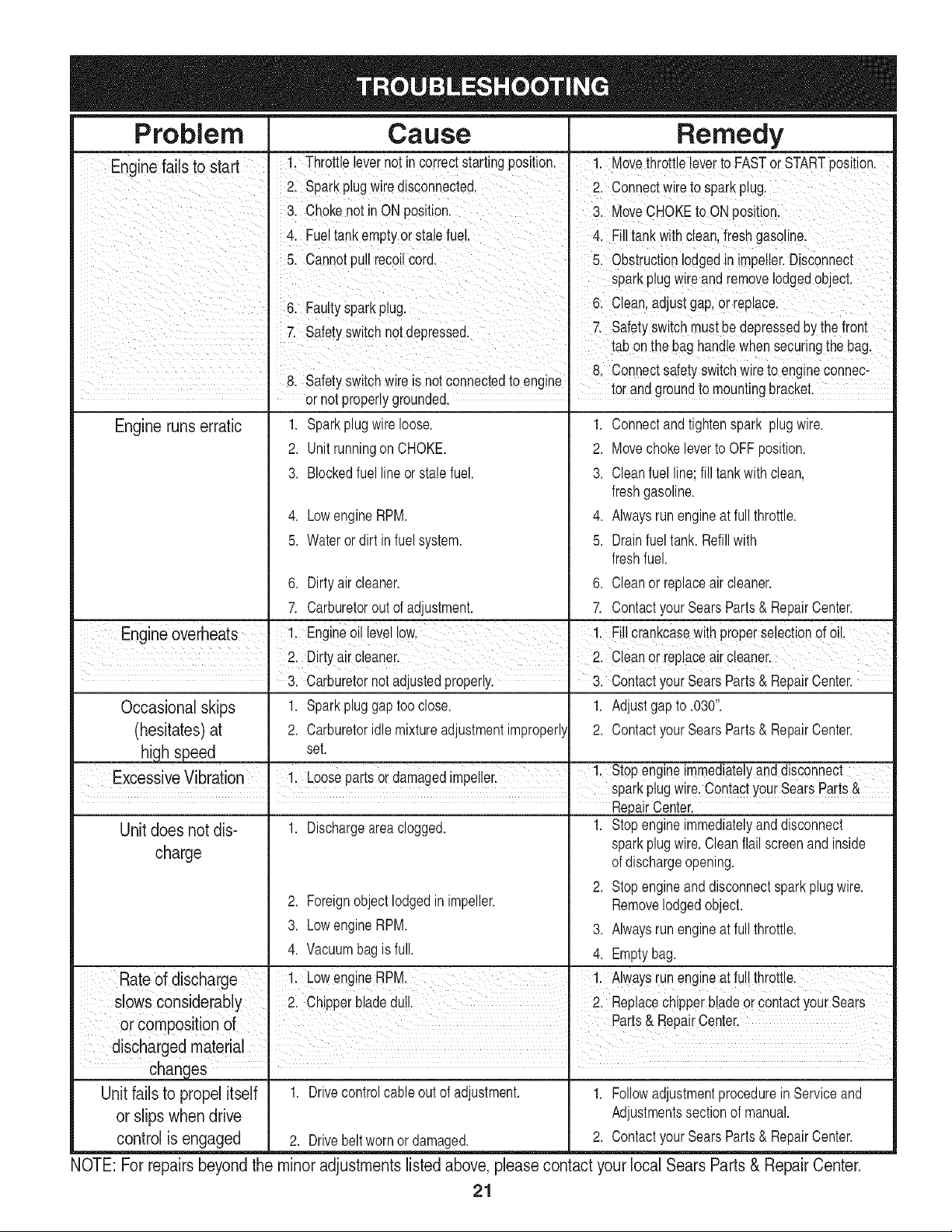
Problem Cause Remedy
Enginefails to start ' 1. Throttlelevernot incorrectstartingposition• 1. Movethrottleleverto FASTor STARTposition.
2. Sparkplugwiredisconnected. 2. Connectwireto sparkplug.
3. Chokenot in ONposition. 3. MoveCHOKEto ONposition.
4. Fueltankemptyor stalefuel• 4. Filltankwith clean,freshgasoline•
5. Cannotpull recoilcord• 5. Obstructionlodgedin mpeller.D sconnect
sparkplugwire andremovelodgedobject,
6 Fault s ark lu 6 Cean adjustgap orrepace
• yp Pg. . .
7 Safetyswtch not depressed 7. Safetyswitchmustbedepressedby the front
• - - ' tab onthe bag hande whensecur ngthe bag
I
' 8. Connectsafety switchwire to engineconnec-
8. Safetyswitchwire is notconnectedto engine tor andgroundto mountingbracket.
• or not properlygrounded.
Engine runs erratic 1. Sparkplug wireloose. 1. Connectand tightenspark plug wire.
2. Unitrunningon CHOKE.
3. Blockedfuel lineor stale fuel.
4. LowengineRPM.
5. Waterordirt in fuel system.
6. Dirty aircleaner.
2. Movechokeleverto OFF position.
3. Cleanfuel line;fill tankwithclean,
freshgasoline.
4. Alwaysrun engineat fullthrottle.
5. Drainfueltank. Refillwith
freshfuel.
6. Cleanor replaceair cleaner.
7. Carburetoroutof adjustment. 7. ContactyourSearsParts& RepairCenter.
Engineoverheats !:Eng in_Oi!levellow 1: Fi!lcrankcaseWithproperselectiond oi!,
I 2: Dirtyair €!eane!i c!eai °! !epla!e ai! €leaie['
3. Carburetornotadjustedproperly. 3. Contactyour SearsParts& RepairCenter.
Occasional skips 1. Sparkpluggap tooclose. 1. Adjustgapto .030".
(hesitates) at 2. Carburetoridlemixtureadjustmentimproperly 2. ContactyourSearsParts & RepairCenter.
high speed set.
. . . _ , 1 Stopengnemmed atey andd sconnect
ExcessiveVibration 1. Loosepartsordamagedimpeller. ' : ,, : . _ _ , .
sparkpug w re_uomacty0ur _ears varts e.
RepairCenter.
Unit does not dis- 1. Dischargeareaclogged. 1. Stopengineimmediatelyand disconnect
charge sparkplugwire. Cleanflailscreenand inside
of dischargeopening.
2. Stopengineanddisconnectspark plug wire.
2. Foreignobject lodgedin impeller. Removelodgedobject.
3. LowengineRPM. 3. Alwaysrun engineat fullthrottle.
4. Vacuumbagis full. 4. Emptybag.
Rateof discharge ! LowengineRPM. !: A!waYsrunengineatfu!!thrott!e.
SlowsCOnsiderab!y 2. Chipperbladedul. 2. ReplacechiPPerb!adeorcontactyoursears
or Compositionof Parts &Repa r CenterI
d scharged mater a I
changes •
Unit fails to propel itself 1. Drivecontrolcableout of adjustment. 1. Followadjustmentprocedurein Serviceand
or slips when drive Adjustmentssectionof manual.
control is engaged 2. Drivebeltwornor damaged. 2. ContactyourSearsParts& RepairCenter.
NOTE: For repairs beyond the minor adjustments listed above, please contact your local Sears Parts & Repair Center.
21
_t B
@
22
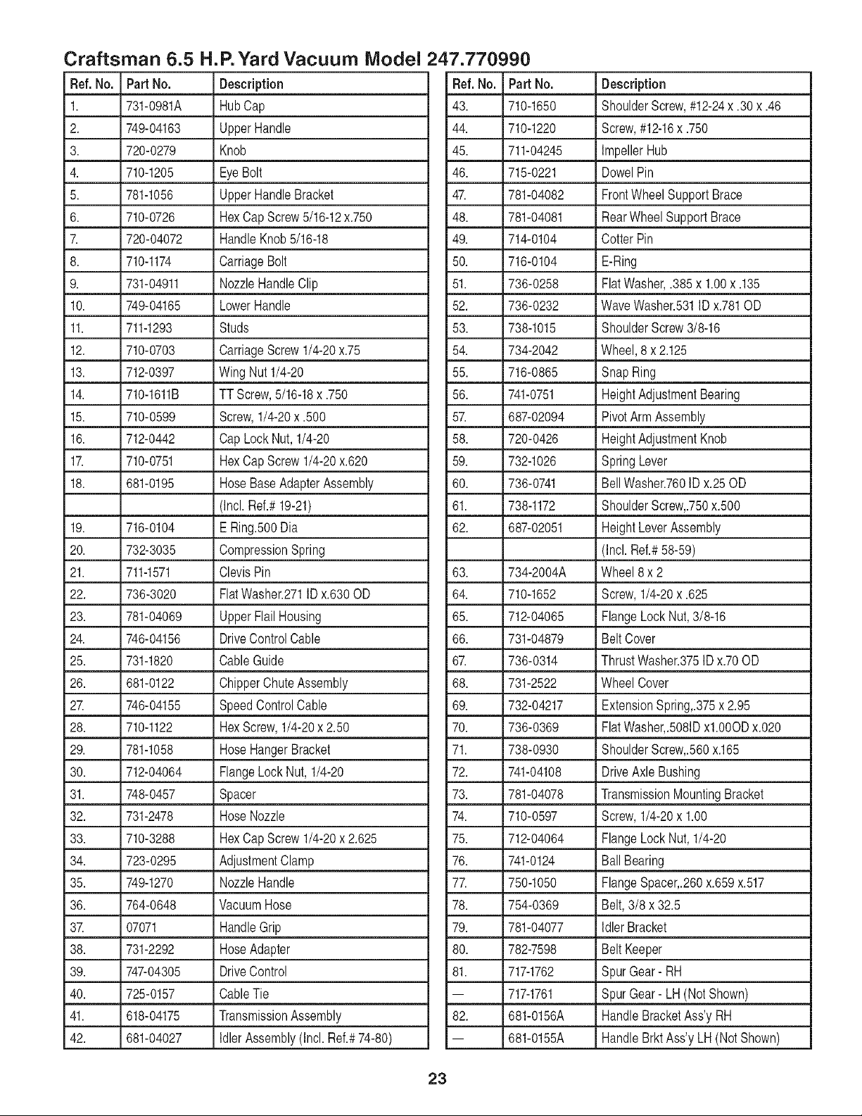
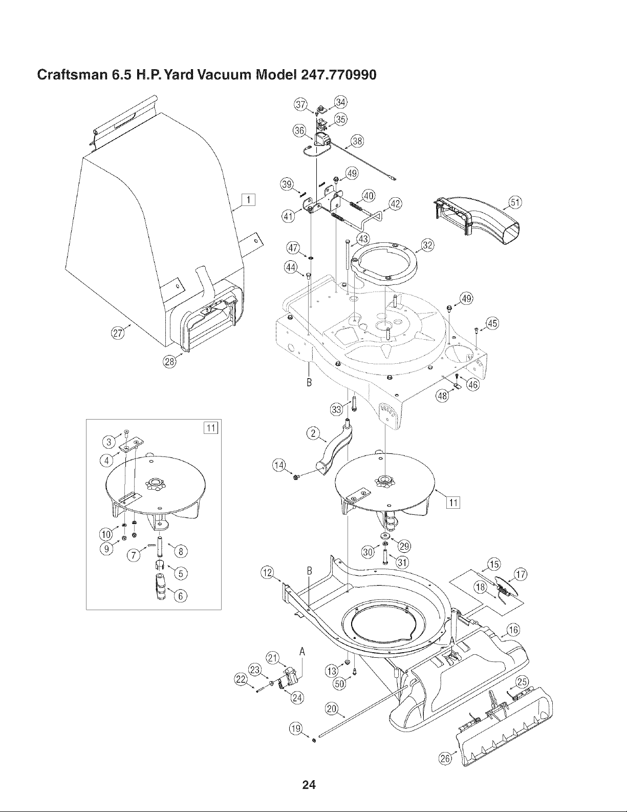
Craftsman 6.5 H.
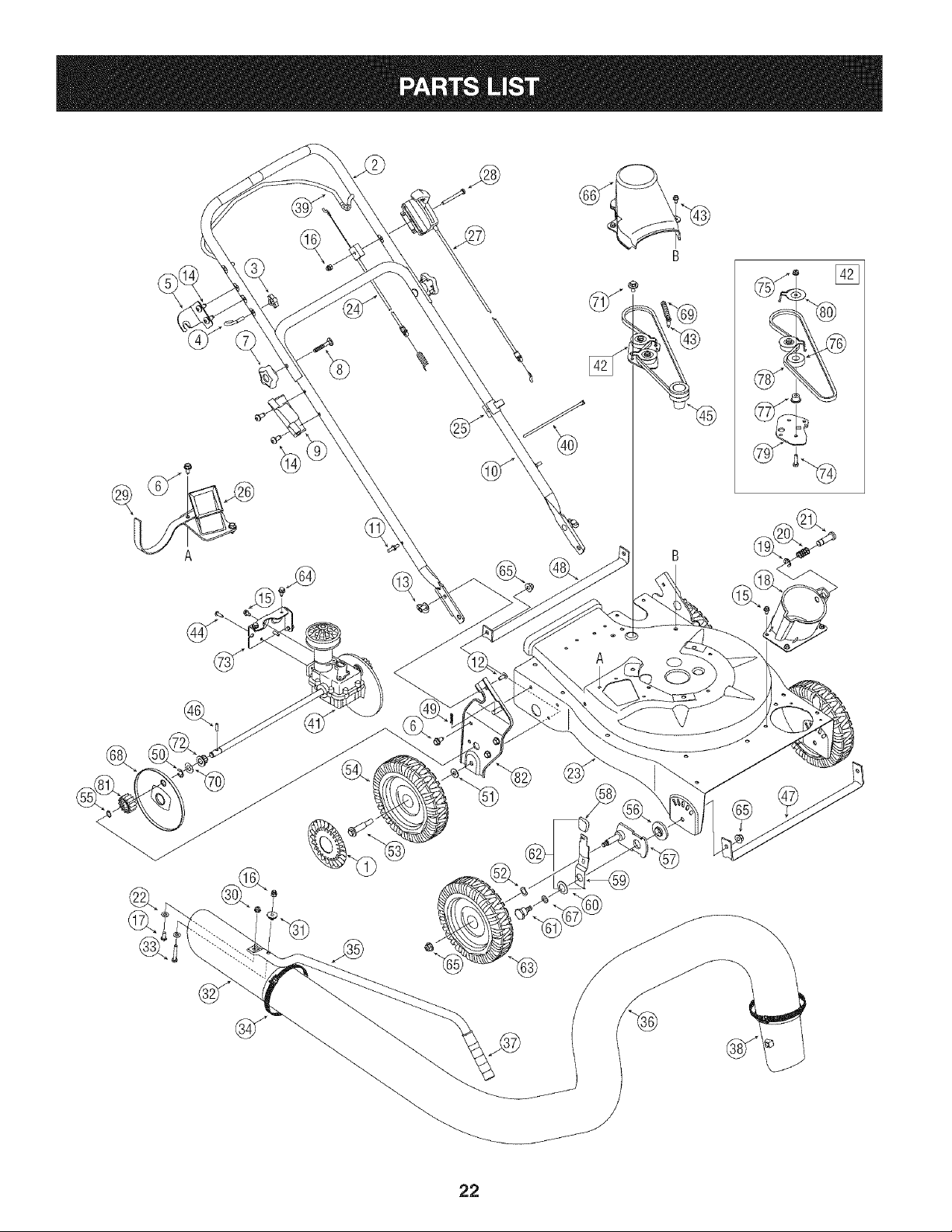
Ref.No. PartNo. Description
1. 731-0981A HubCap
2. 749-04163 UpperHandle
3. 720-0279 Knob
4. 710-1205 EyeBolt
5. 781-1056 UpperHandleBracket
6. 710-0726 HexCap Screw5/16-12x.750
7. 720-04072 HandleKnob5/16-18
8. 710-1174 CarriageBolt
9. 731-04911 NozzleHandleClip
10. 749-04165 LowerHandle
11. 711-1293 Studs
12. 710-0703 CarriageScrew1/4-20x.75
13. 712-0397 Wing Nut1/4-20
14. 710-1611B TT Screw,5/16-18x .750
15. 710-0599 Screw,1/4-20x .500
16. 712-0442 Cap LockNut,1/4-20
17. 710-0751 HexCap Screw1/4-20x.620
18. 681-0195 HoseBaseAdapterAssembly
(Incl.Ref.#19-21)
19. 716-0104 ERing.500Dia
20. 732-3035 CompressionSpring
21. 711-1571 ClevisPin
22. 736-3020 FlatWasher.271ID x.630OD
23. 781-04069 UpperFlail Housing
24. 746-04156 DriveControlCable
25. 731-1820 CableGuide
26. 681-0122 ChipperChute Assembly
27. 746-04155 SpeedControlCable
28. 710-1122 HexScrew,1/4-20x 2.50
29. 781-1058 HoseHangerBracket
30. 712-04064 FlangeLock Nut, 1/4-20
31. 748-0457 Spacer
32. 731-2478 HoseNozzle
33. 710-3288 HexCap Screw1/4-20x 2.625
34. 723-0295 AdjustmentClamp
35. 749-1270 NozzleHandle
36. 764-0648 VacuumHose
37. 07071 HandleGrip
38. 731-2292 HoseAdapter
39. 747-04305 DriveControl
40. 725-0157 CableTie
41. 618-04175 TransmissionAssembly
42. 681-04027 IdlerAssembly(Incl.Ref.#74-80)
P. Yard Vacuum Model 247.770990
Ref. No. Part No. Description
43. 710-1650 ShoulderScrew,#12-24x .30 x .46
44. 710-1220 Screw,#12-16x .750
45. 711-04245 ImpellerHub
46. 715-0221 DowelPin
47. 781-04082 FrontWheelSupportBrace
48. 781-04081 RearWheel SupportBrace
49. 714-0104 CotterPin
50. 716-0104 E-Ring
51. 736-0258 FlatWasher,.385 x 1.00x .135
52. 736-0232 WaveWasher.531ID x.781OD
53. 738-1015 ShoulderScrew3/8-16
54. 734-2042 Wheel,8 x 2.125
55. 716-0865 SnapRing
56. 741-0751 HeightAdjustmentBearing
57. 687-02094 PivotArm Assembly
58. 720-0426 HeightAdjustmentKnob
59. 732-1026 SpringLever
60. 736-0741 BellWasher.760ID x.25 OD
61. 738-1172 ShoulderScrew,.750x.500
62. 687-02051 HeightLeverAssembly
(Incl. Ref.#58-59)
63. 734-2004A Wheel 8 x 2
64. 710-1652 Screw,1/4-20x .625
65. 712-04065 FlangeLockNut,3/8-16
66. 731-04879 BeltCover
67. 736-0314 ThrustWasher.375ID x.70OD
68. 731-2522 Wheel Cover
69. 732-04217 ExtensionSpring,.375x 2.95
70. 736-0369 FlatWasher,.5081Dxl.0OODx.020
71. 738-0930 ShoulderScrew,.560x.165
72. 741-04108 DriveAxle Bushing
73. 781-04078 TransmissionMountingBracket
74. 710-0597 Screw,1/4-20x 1.00
75. 712-04064 FlangeLockNut, 1/4-20
76. 741-0124 BallBearing
77. 750-1050 FlangeSpacer,.260x.659x.517
78. 754-0369 Belt,3/8 x 32.5
79. 781-04077 IdlerBracket
80. 782-7598 Belt Keeper
81. 717-1762 SpurGear- RH
-- 717-1761 SpurGear- LH (NotShown)
82. 681-0156A HandleBracketAss'y RH
-- 681-0155A HandleBrktAss'y LH (Not Shown)
23
Q
Q
24

Craftsman 6.5 H.
Ref.No. PartNo. Description
1 664-0094 BagAssembly
2. 681-0154 ScreenAssembly
3. 710-1054 HexScrew5/16-24x 1.0
4. 781-0490 ChipperBlade
5. 781-0735 PinClip
6. 719-0329 Flail
7. 715-0166 SpiralPin
8. 711-1401 ClevisPin
9. 712-0411 LockNut,5/16-24
10. 736-0119 LockWasher,5/16
11. 681-0152 ImpellerAssembly
(Incl.Ref.#3- 10)
12. 781-0721B LowerFlailHousing
13. 712-04063 FlangeLock Nut 5/16-18
14. 710-0607 Screw,5/16-18x.500
15. 747-04297 HingePin
16. 731-2293A Nozzle
17. 781-1064 BaseAdapterDoor
18. 732-1156 TorsionSpring
19. 726-0106 Cap SpeedNut 1/4
20. 711-1551 PivotRod
21. 731-04967 NozzleDoorLever
22. 710-1256 HexScrew,#8-18x 1.25
23. 750-1294 ShoulderSpacer
24. 732-3118 ExtensionSpring
25. 732-1151A NozzleDoorTorsionSpring
26. 731-2294A NozzleDoor
P. Yard Vacuum Model 247.770990
Ref. No. Part No. Description
27. 764-0631A Bag
28. 631-0083 ChuteAssembly
29. 736-0247 FlatWasher.375ID x 1.25OD
30. 736-0217 LockWasher3/8
31. 710-1273 HexCapScrew,3/8-24x 2.75
32. 631-04118 EngineSpacerAssembly
33. 710-1008 Screw,3/8-16x 1.875
34. 725-1700 SwitchCover
35. 725-3166 SafetySwitch
36. 731-1613 SafetySwitchCover
37. 710-0224 HexWasherScrew#10-16x.50
38. 629-0920A Wire Harness
39. 714-0104 CotterPin
40. 732-0962 CompressionSpring
41. 781-0778A MountingBracket
42. 747-1153 LockRod
43. 710-3195 HexCapScrew5/16-18x 4.5
44. 710-3025 HexCapScrew5/16-18x.625
45. 710-1220 Screw,#12-16x.750
46. 710-0351 Screw#10- 16x.500
47. 736-0607 ExternalL-Washer5/16
48. 726-0139 SpeedNut
49. 710-0726 HexIndexScrew,5/16-12x.750
50. 710-1650 ShoulderScrew,#12-24x .30 x .46
51. 631-0090 BlowerChute
-- 723-0400 SafetyGlasses(Not Shown)
25
Craftsman 6.5 H.P. Engine Model No. 123K02
For Yard Vacuum Model 247.770990
j 1019 LABEL Kl_ 684
50
585
383
635
525 i
524
5O5@
ls8
26
J 1330 REPAIR MANUAL i
i1058 OWNER'S MANUAI.j
306
Craftsman 6.5 H.P. Engine Model No. 123K02
For Yard Vacuum Model 247.770990
425
445
443_
843
%
365
977 CARBURETOR
GASKET SET
633A @
633
61 276_
276_ 12_
968
159
@ 621
188
970
615
404
616
B
|
692 J
633A @
163
127
- 1
33 ®
130
95
m
27
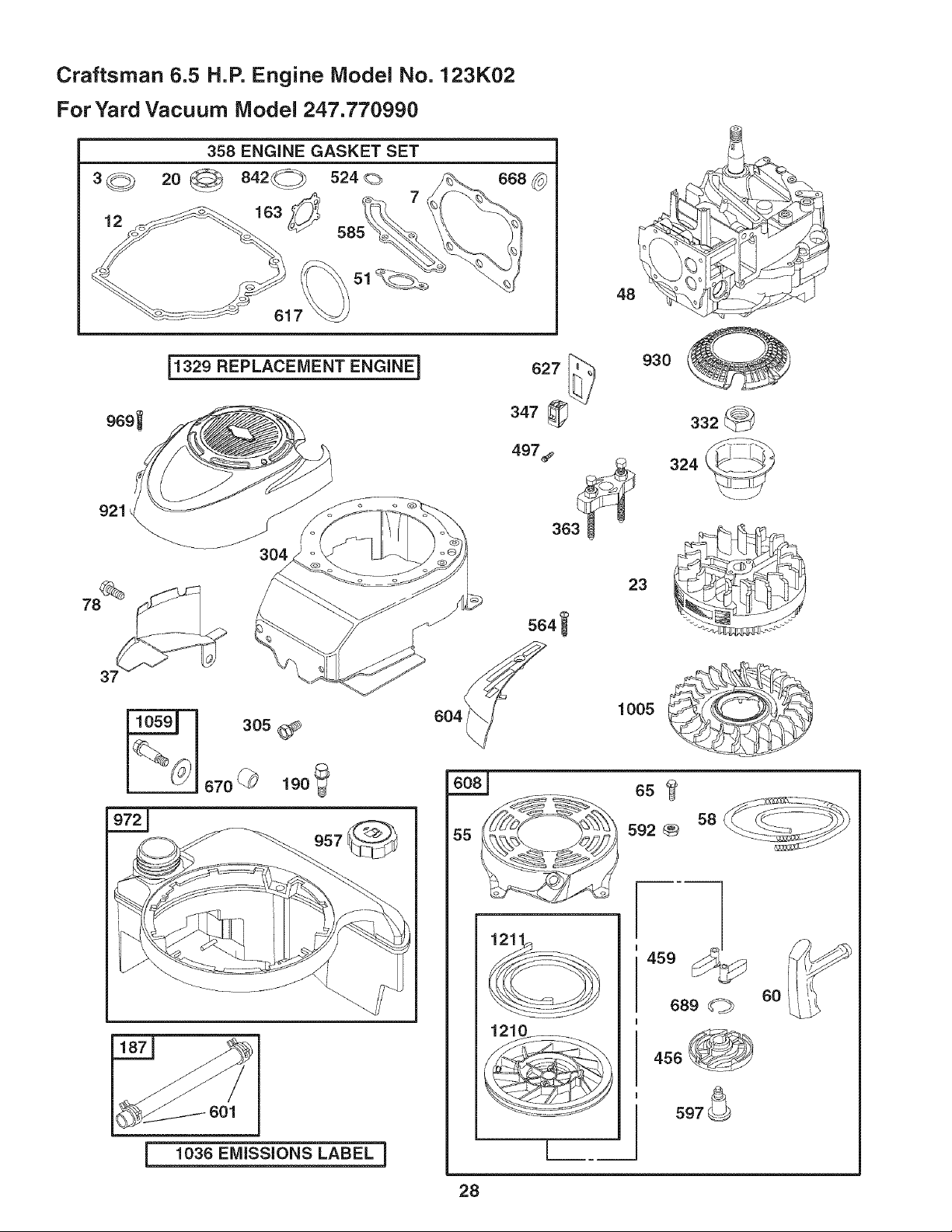
Craftsman 6.5 H.P. Engine Model No. 123K02
For Yard Vacuum Model 247.770990
969_
921
__329 REPLACEMENT ENGINE i
1036 EMiSSiONS LABEL i
28
627 _ 930
347 _ 332
497_ /_---_
1005
58
592
1210 ........
689
456
597 _
6O

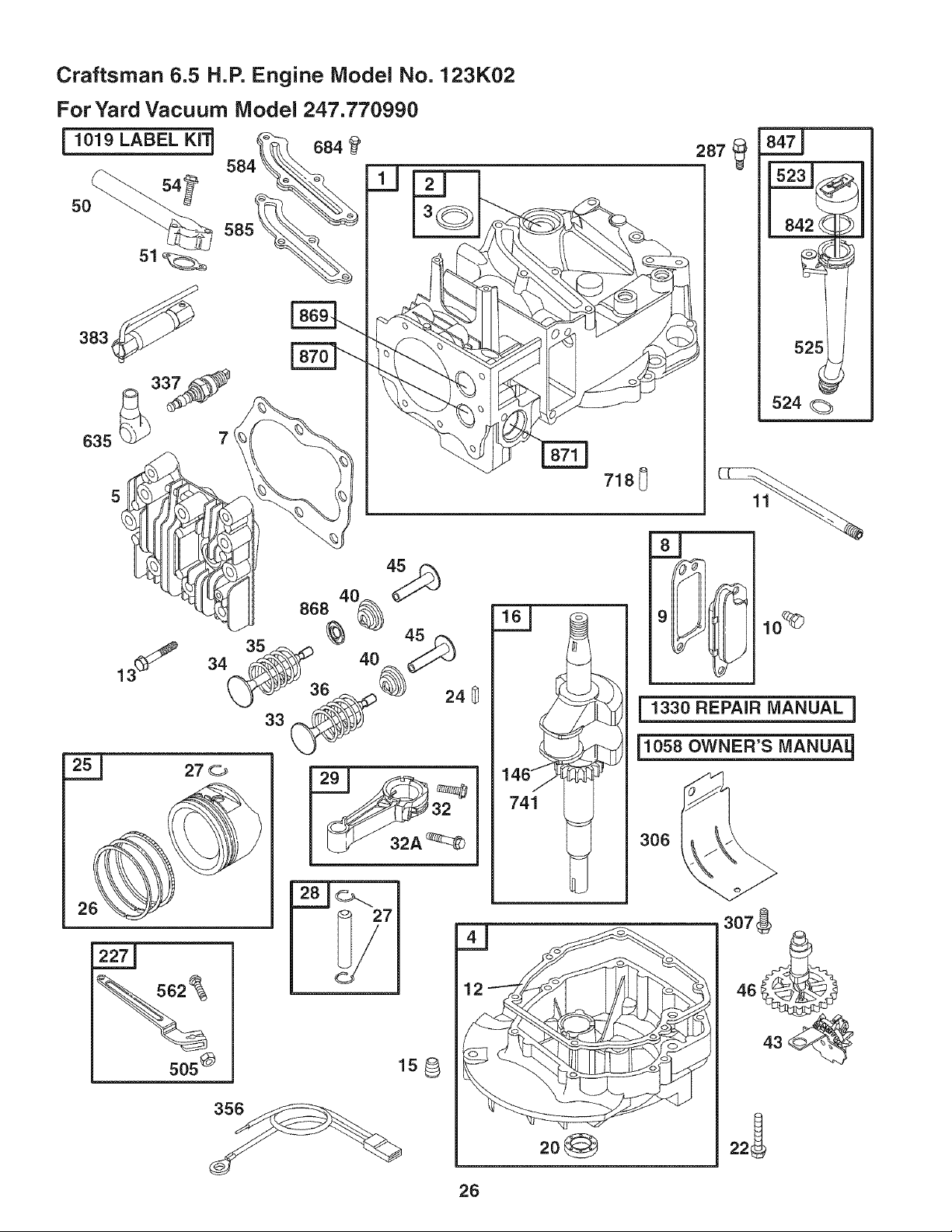
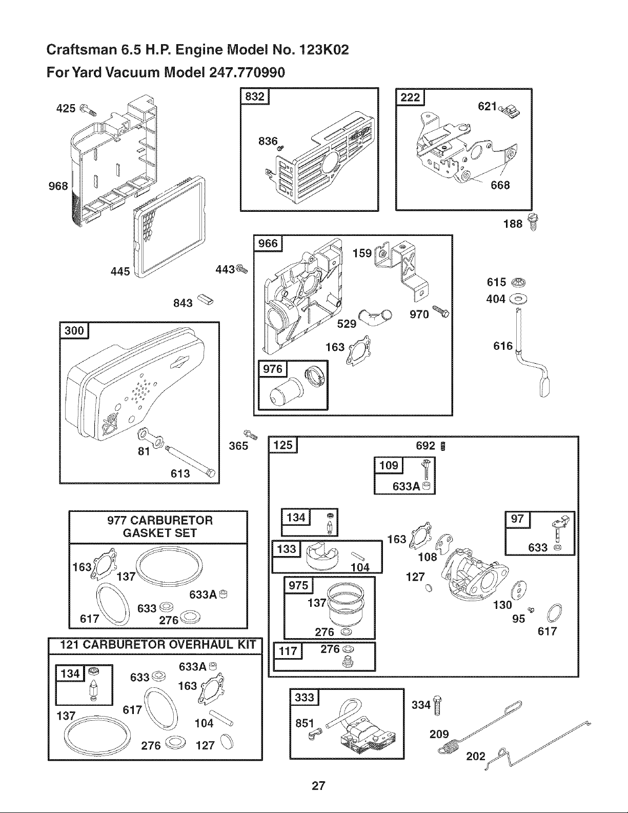
Craftsman 6.5 H.P. Engine Model No. 123K02
For Yard Vacuum Model 247.770990
Ref.No. PartNo. Description
1. 697322 CylinderAssembly
2. 399269 Kit-Bushing/Seal
3. 299819t Seal-Oil(MagnetoSide)
4. 493279 Sump-Engine
5. 691160 Head-Cylinder
7. 692249t Gasket-CylinderHead
8. 695250 BreatherAssembly
9. 699472 Gasket-Breather
10. 691125 Screw(BreatherAssembly)
11. 691260 Tube-Breather
12. 692232t Gasket-Crankcase
13. 690912 Screw(CylinderHead)
15. 691680 Plug-OilDrain
16. 694478 Crankshaft
20. 399781t Seal-Oil(PTOSide)
22. 691092 Screw(EngineSump)
23. 692315 Flywheel
24. 222698 Key-Flywheel
25. 697339 PistonAssembly(Standard)
697341 PistonAssembly(.020"Oversize)
26. 499425 RingSet-Piston(Standard)
499427 RingSet-Piston(.020"Oversize)
27. 691866 Lock-PistonPin
28. 499423 Pin-Piston
29. 499424 Rod-Connecting
32. 691664 Screw(ConnectingRod)
32A. 695759 Screw(ConnectingRod)
33. 262651 Valve-Exhaust
34. 262652 Valve-Intake
35. 691270 Spring-Valve(Intake)
36. 691270 Spring-Valve(Exhaust)
37. 694086 Guard-Flywheel
40. 692194 Retainer-Valve
43. 691997 Slinger-Governor/Oil
45. 690548 Tappet-Valve
46. 691449 Camshaft
48. 498828 ShortBlock
50. 497465 Manifold-Intake
51. 272199t Gasket-Intake
54. 691650 Screw(IntakeManifold)
55. 691421 Housing-RewindStarter
Ref. No. Part No. Description
58. 697316 Rope-Starter(Cutto RequiredLength)
60. 281434 Grip-StarterRope
65. 690837 Screw(RewindStarter)
78. 691108 Screw(FlywheelGuard)
81. 691740 Lock-MufflerScrew
95. 691636 Screw(ThrottleValve)
97. 493267 Shaft-Throttle
104. 691242tt Pin-FloatHinge
108. 691182 Valve-Choke
109. 498593 Shaft-Choke
117. 498978 Jet-Main(Standard)
121. 498260 Kit-CarburetorOverhaul
125. 499059 Carburetor
127. 694468tt Plug-Welch
130. 691203 Valve-Throttle
133. 398187 Float-Carburetor
134. 398188tt Valve-Needle/Seat
137. 693981tt* Gasket-FloatBowl
146. 690979 Key-Timing
159. 691753 Bracket-AirCleanerPrimer
163. 272653t*tt Gasket-AirCleaner
187. 691050 Line-Fuel(Cut to RequiredLength)
188. 693399 Screw(ControlBracket)
190. 690940 Screw(FuelTank)
202. 691829 Link-MechanicalGovernor
209. 691291 Spring-Governor
222. 692150 Bracket-Control
227. 690783 ControlLever-Governor
276. 271716tt* SealingWasher
287. 690940 Screw(DipstickTube)
300. 692038 Muffler
304. 493294 Housing-Blower
305. 691108 Screw(BlowerHousing)
306. 690450 Shield-Cylinder
307. 690345 Screw(CylinderShield)
324. 695161 Cup/ScreenAssembly
332. 690662 Nut(Flywheel)
333. 802574 Armature-Magneto
334. 691061 Screw(ArmatureMagneto)
337. 802592 Plug-Spark
347. 691396 Switch-Rocker
29

Craftsman 6.5 H.P. Engine Model No. 123K02
For Yard Vacuum Model 247.770990
Ref. No. PartNo. Description
356. 496381 Wire-Stop
358. 497316 EngineGasketSet
363. 19069 FlywheelPuller
365. 692524 Screw(Carburetor)
383. 89838 Wrench-SparkPlug
404. 690272 Washer(GovernorCrank)
425. 690670 Screw(AirCleanerCover)
443. 692523 Screw(AirCleanerPrimerBase)
445. 491588 Filter-AirCleanerCartridge
456. 692299 Plate-PawlFriction
459. 281505 PawI-Ratchet
497. 690664 Screw(Stopswitch)
505. 691251 Nut(GovernorControlLever)
523. 495264 Dipstick
524. 692296t Seal-DipstickTube
525. 495265 Tube-Dipstick
529. 691923 Grommet
562. 92613 Bolt (GovernorControlLever)
564. 698589 Screw(ControlCover)
584. 697734 Cover-BreatherPassage
585. 691879t Gasket-BreatherPassage
592. 690800 Nut(RewindStarter)
597. 691696 Screw(PawlFrictionPlate)
601. 95162 Clamp-Hose
604. 698588 Cover-Control
608. 497680 Starter-Rewind
613. 691340 Screw(Muffler)
615. 690340 Retainer-GovernorShaft
616. 698801 Crank-Governor
617. 270344t*tt Seal-ORing(intakeManifold)
621. 692310 Switch-Stop
627. 692872 Bracket-Stopswitch
633. 691321tt * Seal-Choke/ThrottleShaft
633A. 693867tt * Seal-Choke/ThrottleShaft
635. 66538 Boot-SparkPlug
668. 493823 Spacer
670. 692294 Spacer-FuelTank
Ref. No. Part No. Description
684. 690345 Screw(BreatherPassageCover)
689. 691855 Spring-Friction
692. 690579 Spring-Detent
718. 690959 Pin-Locating
741. 790345 Gear-Timing
832. 499034 Guard-Muffler
836. 690664 Screw(MufflerGuard)
842. 691031t Seal-ORing(DipstickTube)
843. 691884 Sleeve-Lever
847. 692017 Assembly-Dipstick/Tube
851. 493880 Terminal-SparkPlug
868. 697338 Seal-Valve
869. 691155 Seat-Valve(intake)
870. 690380 Seat-Valve(Exhaust)
871. 262001 Bushing-Guide(Exhaust)
63709 Bushing-Guide(intake)
921. 698587 Cover-BlowerHousing
930. 691919 Guard-Rewind
957. 397974 Cap-FuelTank
966. 496116 Base-AirCleanerPrimer
968. 692298 Cover-AirCleaner
969. 690700 Screw(BlowerHousingCover)
970. 691669 Screw(AirCleanerPrimerBracket)
972. 699374 Tank-Fuel
975. 493640 Bowl-Float
976. 694395 Primer-Carburetor
977. 498261 Set-CarburetorGasket
1005. 691346 Fan-Flywheel
1019. 494256 Kit-Label
1036. 697457 Label-Emission
1058. MS5244 Owner'sManual
1059. 692311 Kit-Screw/Washer
1210. 498144 Assembly-Pulley/Spring(Pulley)
1211. 498144 Assembly-Pulley/Spring(Spring)
1329. 123K02- ReplacementEngine
0240-E1
1330. 272147 RepairManual
tlncluded in EngineGasketSet, Key.No. 358
ttlncluded in CarburetorOverhaulKit, Key.No. 121
*includedin CarburetorGasketSet, Key.No. 977
30

STOP
TO AVOID SERIOUS iNJURY
. READ OPERATOR'S MANUAL _
, KEEP HANDS OUT OF INLET AND DISCHARGE OPENINGS WHEE MACHINE
iS RUNNING. ROTATINGBLADESARE iNSiDE.
, TURN ENGINE OFF AND ALLOW iMPELLER TO COME TO COMPLETE STOP _
BEFORE REMOVING BAG.
, DO NOT ATTEMPTTO CLEARACLOG ORJAM WITH THE ENGINERUNNING.
" DO NOT OPERATE UNE WITHOUT BAG OR OPTIONAL BLOWER CHUTE iN IT1 _PLACE.
| o%° ss % " ||
, DONOTOPERATEWHENCHILDRENOROTHERSAREAROUND. _ _
"WEAR APPROVED SAFETY GLASSES.
• KEEP HANDS OUT OF DISCHARGE OPEN|NG.
,DO NOT STAND OR WALK |N FRONT OF
D|SCHARGE OPEN|NG OR A|M |T AT
BYSTAN_RS. O_ECTS THROWN OUT OF
CHUTE CAN CAUSE PERSONAL iNJURY.
,,KEEP DHiU)REN AND OTHERS AWAY. $30270
WARNING
This symbol points out
importantsafety instructions
which, if not followed,could
endangerthe personal safety
and/or propertyof yourself
and others. Readand follow
all instructionsin this manual
beforeattemptingto operate
this machine.Failureto com-
ply with these instructions
mayresult in personalinjury.
When you see this symbol.
HEED iTS WARNING!
Your Responsibility
Restrictthe use of this
power machine to persons
who read, understandand
follow the warnings and
instructions in this manual
and on the machine.
31
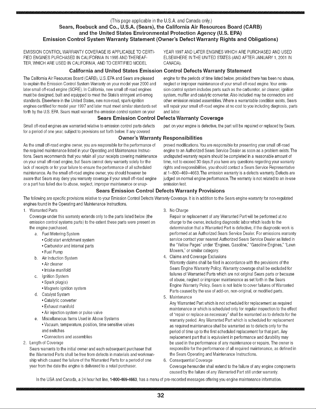
(Thispageapplicablein the U.S.A.and Canadaonly.)
Sears, Roebuck and Co., U.S.A. (Sears), the California Air Resources Board (CARB)
and the United States Environmental Protection Agency (U.S. EPA)
Emission Control System Warranty Statement (Owner's Defect Warranty Rights and Obligations)
EMISSIONCONTROLWARRANTYCOVERAGEISAPPLICABLETO CERTI- YEAR 1997AND LATERENGINESWHICHARE PURCHASEDAND USED
FlED ENGINESPURCHASEDIN CALIFORNIAIN 1995ANDTHEREAF- ELSEWHEREINTHE UNITEDSTATES(ANDAFTERJANUARY1,2001 IN
TER,WHICHARE USED IN CALIFORNIA,ANDTOCERTIFIEDMODEL CANADA).
California and United States Emission Control Defects Warranty Statement
The CaliforniaAir ResourcesBoard(CARB),U.S.EPAandSearsare pleased
to explainthe EmissionControlSystemWarrantyon your modelyear2000 and
latersmalloff-roadengine(SORE).In California,newsmall off-roadengines
mustbe designed,builtand equippedto meettheState'sstringentanti-smog
standards.Elsewhereinthe UnitedStates, newnon-road,spark-ignition
enginescertifiedfor modelyear 1997and latermustmeetsimilarstandardsset
forth bythe U.S.EPA.Sears mustwarranttheemissioncontrol systemonyour
enginefor the periodsof timelistedbelow,providedtherehas beenno abuse,
neglector impropermaintenanceof your smalloff-roadengine.Youremis-
sion controlsystemincludespartssuch as thecarburetor,air cleaner,ignition
system,mufflerand catalyticconverter.Also includedmaybe connectorsand
otheremissionrelatedassemblies.Wherea warrantableconditionexists,Sears
will repairyour smalloff-roadengine at no cost to youincludingdiagnosis,parts
and labor.
Sears Emission Control Defects Warranty Coverage
Smalloff-roadenginesarewarrantedrelativeto emissioncontrol partsdefects
fora period of oneyear,subjectto provisionsset forthbelow.Ifany covered
Owner's Warranty
Asthe smalloff-roadengineowner,you are responsiblefor the performanceof
therequiredmaintenancelistedinyour Operatingand MaintenanceInstruc-
tions.Sears recommendsthatyou retainall your receiptscoveringmaintenance
on yoursmall off-roadengine,butSearscannotdenywarrantysolelyforthe
lackof receiptsorfor yourfailureto ensurethe performanceof all scheduled
maintenance.Asthe smalloff-roadengineowner,you shouldhoweverbe
awarethat Sears maydenyyou warrantycoverageif your smalloff-roadengine
ora part hasfaileddueto abuse,neglect,impropermaintenanceor unap-
part onyour engineis defective,the part willbe repairedor replacedbySears.
Responsibilities
provedmodifications.Youare responsiblefor presentingyour smalloff-road
engineto an AuthorizedSearsService Dealeras soonas a problemexists.The
undisputedwarrantyrepairsshouldbe completedina reasonableamountof
time,not to exceed30 days.Ifyou haveany questionsregardingyourwarranty
rightsand responsibilities,you shouldcontacta SearsServiceRepresentative
at 1--800--469--4663.Theemissionwarrantyis a defectswarranty.Defectsare
judgedon normalengineperformance.Thewarrantyis not relatedto an in-use
emissiontest.
Sears Emission Control Defects Warranty Provisions
ThefollowingarespecificprovisionsrelativetoyourEmissionControlDefectsWarrantyCoverage.It isinadditionto theSearsenginewarrantyfornon-regulated
enginesfound in theOperatingandMaintenanceInstructions.
1. WarrantedParts
Coverageunderthis warrantyextendsonly to the parts listed below(the
emissioncontrol systemsparts)to the extentthese parts werepresenton
theengine purchased.
a. FuelMeteringSystem
• Coldstart enrichmentsystem
• Carburetorand internal parts
• FuelPump
b. Airlnduction System
• Air cleaner
• Intakemanifold
c. IgnitionSystem
• Sparkplug(s)
• Magnetoignitionsystem
d. CatalystSystem
• Catalyticconverter
• Exhaustmanifold
• Air injectionsystemor pulsevalve
e. MiscellaneousItemsUsed inAboveSystems
• Vacuum,temperature,position,timesensitive valves
andswitches
• Connectorsand assemblies
2. Lengthof Coverage
Searswarrantsto the initialownerand eachsubsequentpurchaserthat
theWarrantedParts shall befree from defectsin materialsandworkman-
ship whichcausedthe failureof the WarrantedPartsfor a periodof one
yearfromthe datethe engineis deliveredto a retailpurchaser.
3. NoCharge
Repairor replacementof any WarrantedPartwill be performedat no
chargeto the owner,includingdiagnosticlabor whichleads to the
determinationthata WarrantedPartis defective,ifthe diagnosticwork is
performedat an AuthorizedSears ServiceDealer.For emissionswarranty
servicecontact your nearestAuthorizedSears ServiceDealeras listed in
the "YellowPages"under"Engines,Gasoline,""GasolineEngines,""Lawn
Mowers,"or similarcategory.
4. Claimsand CoverageExclusions
Warrantyclaimsshall be filed in accordancewiththe provisionsofthe
Sears EngineWarrantyPolicy.Warrantycoverageshall be excludedfor
failures of WarrantedPartswhichare not originalSears parts or because
of abuse,neglector impropermaintenanceas setforth in theSears
EngineWarrantyPolicy.Searsis not liable to coverfailuresof Warranted
Partscausedby the useof add-on,non-original,or modified parts.
5. Maintenance
Any WarrantedPartwhich is notscheduledfor replacementas required
maintenanceor which is scheduledonly for regularinspectionto the effect
of "repairor replace as necessary"shall be warrantedas to defectsfor the
warrantyperiod.Any WarrantedPartwhich is scheduledfor replacement
as requiredmaintenanceshallbe warrantedasto defectsonly for the
periodof time up to the first scheduledreplacementforthat part. Any
replacementpart that is equivalentin performanceand durabilitymay
be usedin theperformanceof any maintenanceor repairs.The owneris
responsibleforthe performanceof all requiredmaintenance,as definedin
the SearsOperating andMaintenanceInstructions.
6. ConsequentialCoverage
Coveragehereundershallextend to thefailure of any enginecomponents
caused bythefailure of anyWarrantedPartstill underwarranty.
Inthe USAand Canada,a 24 hour hot line, 1-800-469-4663,has a menuof pre-recordedmessagesofferingyou enginemaintenanceinformation.
32
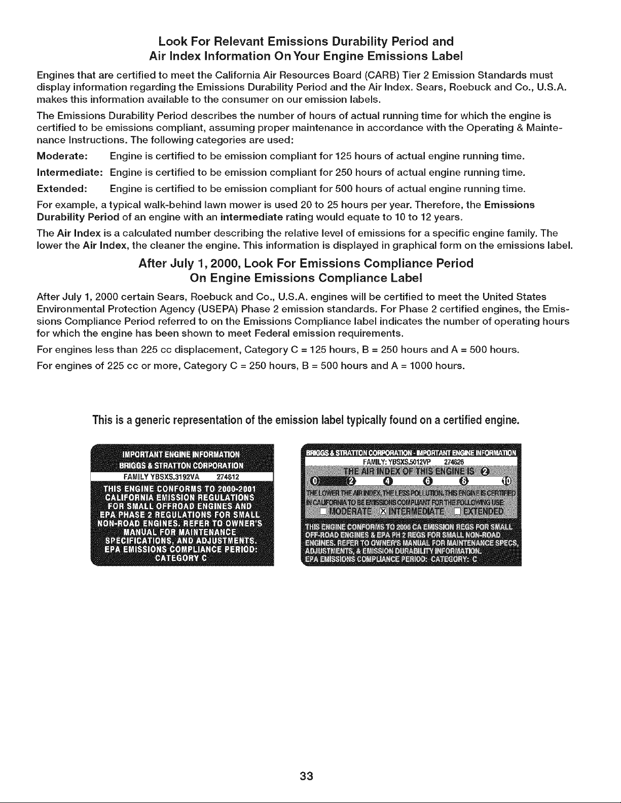
Look For Relevant Emissions Durability Period and
Air index information On Your Engine Emissions Label
Engines that are certified to meet the California Air Resources Board (CARB) Tier 2 Emission Standards must
display information regarding the Emissions Durability Period and the Air Index. Sears, Roebuck and Co., U.S.A.
makes this information available to the consumer on our emission labels.
The Emissions Durability Period describes the number of hours of actual running time for which the engine is
certified to be emissions compliant, assuming proper maintenance in accordance with the Operating & Mainte-
nance instructions. The following categories are used:
Moderate: Engine is certified to be emission compliant for 125 hours of actual engine running time.
intermediate: Engine is certified to be emission compliant for 250 hours of actual engine running time.
Extended: Engine is certified to be emission compliant for 500 hours of actual engine running time.
For example, a typical walk-behind lawn mower is used 20 to 25 hours per year. Therefore, the Emissions
Durability Period of an engine with an intermediate rating would equate to 10 to 12 years.
The Air index is a calculated number describing the relative level of emissions for a specific engine family. The
lower the Air index, the cleaner the engine. This information is displayed in graphical form on the emissions label.
After July 1,2000, Look For Emissions Compliance Period
On Engine Emissions Compliance Label
After July 1, 2000 certain Sears, Roebuck and Co., U.S.A. engines will be certified to meet the United States
Environmental Protection Agency (USEPA) Phase 2 emission standards. For Phase 2 certified engines, the Emis-
sions Compliance Period referred to on the Emissions Compliance label indicates the number of operating hours
for which the engine has been shown to meet Federal emission requirements.
For engines less than 225 cc displacement, Category C = 125 hours, B = 250 hours and A = 500 hours.
For engines of 225 cc or more, Category C = 250 hours, B = 500 hours and A = 1000 hours.
This is a generic representationof the emission labeltypically found on a certified engine.
33
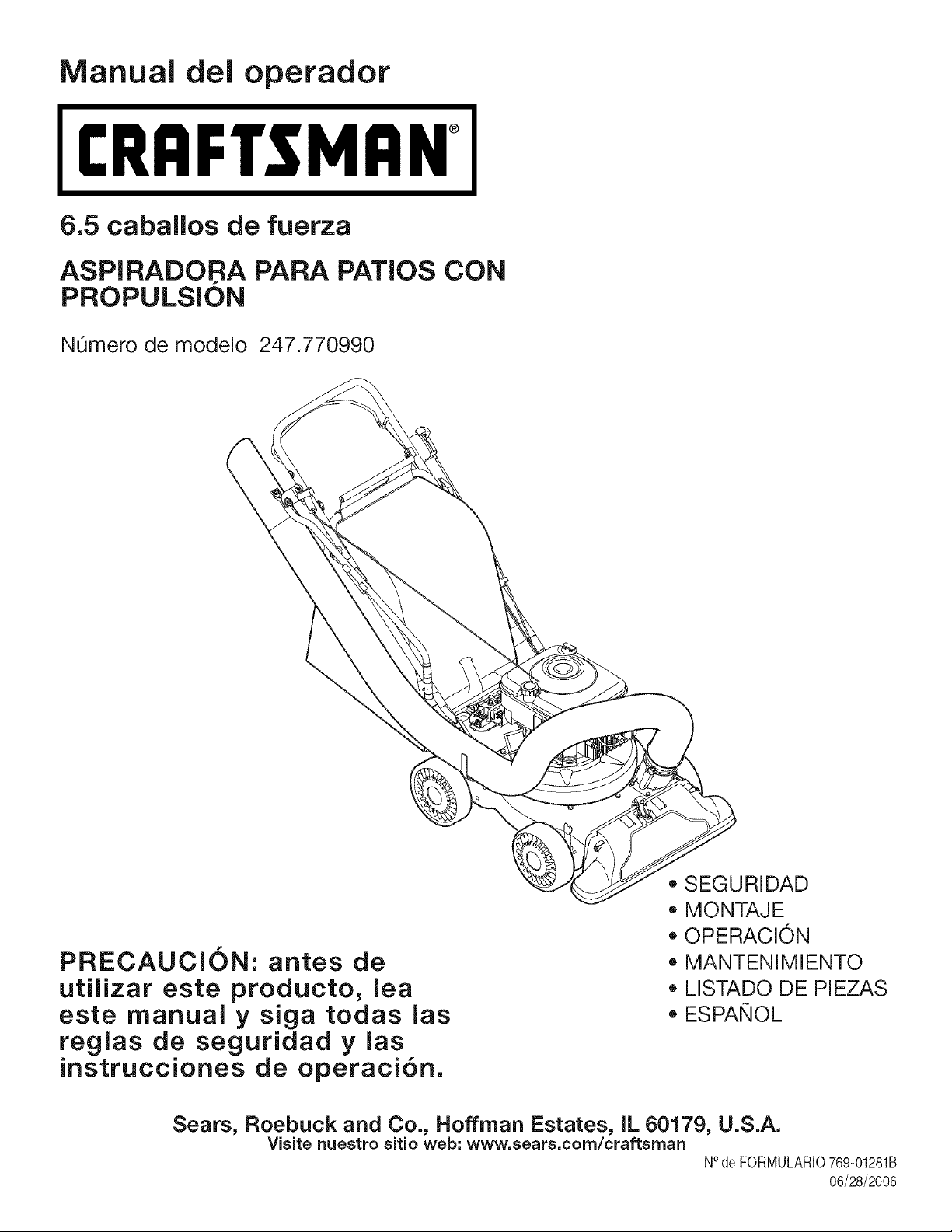
Manual dei operador
I:RRFTSMRN°
6.5 caballos de fuerza
ASPIRADORA PARA PATIOS CON
PROPULSION
NOmero de modelo 247.770990
PRECAUCION: antes de
utilizar este producto, lea
este manual y siga todas las
reglas de seguridad y las
instrucciones de operaci6n.
• SEGURIDAD
MONTAJE
OPERACION
MANTENIMIENTO
LISTADO DE PIEZAS
ESPANOL
Sears, Roebuck and Co., Hoffman Estates, IL 60179, U.S.A.
Visite nuestro sitio web: www.sears.corn/craftsrnan
NOde FORMULARIO769-01281B
06/28/2006
Declaraci6n de garantia ...................... PAgina 2
Acuerdo de Protecci6n Para
Reparaciones ....................................... PAgina 3
PrActicas operaci6n seguras ............... PAginas 4-5
Montaje ................................................ PAginas 6-9
Operaci6n ............................................ PAginas 10-13
Mantenimiento ..................................... PAginas 14-15
Servicio y ajuste ................................ PAginas 16-19
Almacenamiento fuera de temporada.... PAgina 20
Soluci6n de problemas ...................... PAgina 21
Etiquetas de seguridad ....................... PAgina 22
NOmero de servicio ..................... Cubierta posterior
Garantiacompletade un aho para la aspiradora parapatiosCraftsman
Esteequipoesta cubiertopor una garanfiade un aho,siempreque se mantenga,lubriquey ajustede acuerdoconlas instruccionesdelpresente
manualdel operador.Duranteel aho de garanfia,si este equiposufre cualquierfallaproducidapordefectosen materialeso manode obra,
DEVUELVALOA SUCENTRODE PARTES& REPARACIONSEARSM_,SCERCANO,y SearsIorepararAsin ningOncargo.Elserviciode
garanfiaa domicilioestAdisponibleperose aplicarAun cargode traslado.
Esta garantia no cubre:
• Artfculosde duraci6nlimitadaque sufrendesgastebajo condicionesnormalesde uso, talescomo bujiasde encendido,purificadoresde aire,
correasy filtrosde aceite.
Reemplazoo reparacionesde Ilantascausadaspor pinchadurasconobjetosexteriorescomo,porejemplo,clavos,espinas,palosovidrios,etc.
Reparacionesnecesariasdebidoa abusodel operador,incluyendo,perosin limitarsea ellos,losdahoscausadosporobjetos,tales como
piedras,desechosde metalo trozosde maderade un tamahodemasiadogrande,objetosquehacenimpactoquepuedendoblarla estruc-
turao el carter,o sobreacelerarel motor.
Reparacionesnecesariasdebidoa negligenciadeloperador,incluyendoentreotros,dahosmecanicoy el_ctricoocasionadoporunalmace-
namientonoapropiado,fallapor el uso de aceitede gradoy/o cantidadno apropiadao falla por no dar mantenimientoal equipode acuerdo
con las instruccionescontenidasen el manualdel operador.
Limpiezao reparacionesal motor(sistemadecombustible)provocadasporuncombustiblecontaminadou oxidado(viejo).En general,el
combustibledebeutilizarseen unperiodono mayorde 30 diasa partir de su adquisici6n.
Equiposutilizadosparafines comercialeso de alquiler.
PARAUBICAREL CENTRODEPARTESY REPARACIONSEARSM_,SCERCANO0 PARAPROGRAMAREL SERVlCIOTECNICO,
SIMPLEMENTECOMUNiQUESECONSEARSALTELEFONO1-800-4-MYHOME®.
Estagaranfiale otorgaderechoslegalesespecificos;ustedtambienpuedetenerotros derechos,loscualesvarian deunestadoaotro.
SEARS, ROEBUCK AND CO., D/817WA, HOFFMAN ESTATES, IL 60179
Caballos de fuerza :
Tipo de aceite del motor:
Capacidad de aceite del motor:
Capacidad de combustible:
Bujias:
Separaci6n de las bujias:
6.5
SAE 30
18 onzas
1 1/2 2 cuartos
Champion® RJ19LM
.030"
NOmero de modelo ......................................................
NOmero de serie ...........................................................
Fecha de compra .........................................................
Registre arriba el nQmero del modelo, el nQmero
de serie y la fecha de compra
35
Felicitacionespor haberrealizadouna adquisici6ninteligente.El
productoCraftsman@que haadquiridoest,.disehadoy fabricado
parabrindarmuchosahosde funcionamientoconfiable.Perocomo
todoslosproductosa vecespuederequerirde reparaciones.Esen
ese momentocuandoel disponerde un Acuerdode protecci6npara
reparacionesle puedeahorrardineroy problemas.
Acontinuaci6nse detallanlos puntosincluidosen el Acuerdo:
, Servicio experto prestadopor nuestros12,000especialistasen
reparacionesprofesionales
Servicio ilimitadosin cargo paralas piezasy la manode obra en
todaslas reparacionescubiertas
• Reemplazodel productosi noes posiblerepararelproducto
cubierto
Descuentode 10%del precionormaldel servicioy de las piezas
relacionadascon el mismoqueno esten cubiertaspor el acuerdo;
adem_ts,10%del precionormalde la verificaci6nde manten-
imientopreventivo
, Ayudar_pida portel_fono- asistenciatelef6nicaa cargode un
tecnicode Searspara los productosque requierenreparaci6n
a domicilio,adem_tsde una programaci6nconvenienteparala
reparaci6n
Unavezadquiridoel Acuerdo,puede programarelserviciocon
tan s61orealizaruna Ilamadatelef6nica.Puede Ilamaren cualquier
momentodel dia o de la nocheo programarunservicioen linea.
Searsdisponede m_.sde 12.000especialistasenreparaciones
profesionalesque tienenaccesoa m_tsde4.5 millonesde piezasy
accesoriosde buenacalidad.Estees el tipo de profesionalismoen
el quepuedeconfiarpara que le ayudea prolongarla vida 0til del
productorecientementeadquiridoen losahos por venir,iAdquierahoy
su acuerdodeprotecci6npara reparaciones!
Se aplican determinadaslimitacionesy exclusiones.Paraobtener
informaci6nadicional y preciosIlameal 1-800-827-6655.
Serviciode instalaci6nde Sears
Sideseasolicitarla instalaci6nprofesionalde Searsde aparatos
dom_sticos,dispositivospara abrir portones,calentadoresde agua y
otrosarticulosdom_sticosimportantes,en losEstadosUnidosIlame
al 1-800-4-MY-HOME@.
36
ADVERTENCIA:elescapedelmotordeesteproducto,algunosdesuscornponentesy algunoscorn-
ponentesdelvehiculocontbnenoernitenproductosquirnicosqueelestadodeCaliforniaconsideraque
puedenproducircancer,defectosdenacirnientou otrosproblemasreproductivos.
PELIGRO:estarn_.quinaest,.diseSadaparaserutilizadarespetandolasreglasdeseguridadcontenidasenestemanual.
AIigualqueconcualquiertipodeequipoelectrico,undescuidooerrorpotpartedeloperadorpuedeproducirlesiones
graves.Estarn_.quinaescapazdearnputarrnanosy piesy dearrojarobjetoscongranfuerza.Denorespetarlasinstruc-
clonesdeseguridadsiguientessepuedenproducirlesionesgraveso larnuerte.
ADVERTENCIA:Estesirnboloindicainstruccionesdeseguridadirnportantesquedenoseguirse,se
podriaponerenpeligrola seguridadpersonaly/olapropiedadsuyay deterceros.Leay sigatodaslas
instruccionesenestemanualantesdeiniciarlaoperaci6ndeestarn_.quina.Encasodenoseguirestas
instruccionespodriaprovocarbsionespersonales.Cuandoveaestesirnbolo.SlGALA ADVERTENClA.
Capacitaci6n
1. Lea, entienday cumplatodas las instruccionesincluidasen la maquinay
en los manualesantes de montarlay utilizarla.Guardeeste manualen un
lugar seguroparaconsultasfuturasy regulares,asi come para solicitar
repuestos.
2. Familiarfcesecon todos loscontrolesy su operaci6nadecuada.Sepa
c6modetenerla maquinay comodesengranarloscontrolesrapidamente.
3. No permitanuncaque losnihos menoresde 16 aSosutilicen esta
ma.quina.Los ni_osde 16aSosy masmayoresdebenleery comprender
las instruccionesde operaciony las reglasde seguridad contenidasen
estemanual,y tambiendebenser capacitadosy estarsupervisadospor
unode lospadres.
4. Nunca permitaque los adultosoperen estamaquinasinrecibir antesla
instruccionapropiada.
5. Mantengaa lostranseuntes,ayudantes,mascotasy nihosal menosa
75 pies de la maquinamientrasesta operando.Detengala maquinasi
alguienentra en lazona.
6. Nunca enciendaun motoren espacioscerradoso en unazonacon poca
ventilaci6n.Elescapedel motorcontiene monoxidodecarbono,un gas
inodoroy letal.
7. No pongalas maneso los piescerca de las piezasrotatoriaso en las
camarasdealimentacionni en laabertura de descarga.El contactoconel
motorrotatoriopuede producirla amputaciondededos, maneso pies.
8. Nuncatrate de destapar la toma de alimentaci6no la aberturade
descarga,nitrate de sacar o vaciarla bolsade la aspiradora,nide revisar
y repararla maquinamientrasel motorestaen marcha.Apagueel motor
y esperehastaquetodas las piezasmovilesse hayandetenidoper
complete.Desconecteel cable de la bujb y pongalode maneraquehaga
masacontrael motor.
Preparativos
1. Inspeccioneminuciosamenteelareadondeutilizaraelequipo.Retiretodaslas
piedras,botellas,latasu otrosobjetosextradosquepuedanserlevantadoso
arrojadoscausandolesionespersonaleso daSosa lamaquina.
2. Paraprotegerselos ojosutilice siempreanteojoso antiparrasde
seguridadmientrasopera la maquinao mientrasla ajustao repara.Los
objetos arrojadosque rebotanpuedenlesionargravementelavista.
3. Utilicezapatosde trabajo resistentes,de suelafuerte, asi como
pantalonesy camisasajustados.Lasprendassueltaso lasalhajas
pueden quedaratrapadasen laspiezasmoviles.Nuncautilice la maquina
descalzoo con sandalias. Utiliceguantesde trabajode cuero cuando
alimentematerialporel canalde lacortadora.
4. Antesde encenderla maquinacontrolequetodoslospernosy tornillosesten
bienajustadosparacomprobarquela maquinaseencuentraen condiciones
segurasde operaci6n.Ademas,realiceunainspeccionvisualde la maquinaa
intervalosfrecuentesparacontrolarsi la mismaestadaSada.
5. Mantengao reemplacelas etiquetasde seguridade instruccionessegt]n
sea necesario.
6. Paraevitarlesionespersonaleso dados materialessea sumamente
cuidadosoal manipularlagasolina. La gasolinaes altamenteinflamabley
sus vaporespuedencausarexplosiones.Se puedelesionar gravementesi
derramagasolinasobreusted o sobre la ropaya que se puede encender.
Lavesela piel y cambiesede ropade inmediato.
a. Utilices61orecipientespara gasolinaautorizados.
b. Apaguetodoslos cigarrillos,cigarros,pipasy otrasfuentesde combustion.
c. Nuncacarguecombustibleen la ma.quinaen un espaciocerrado.
d. Nuncasaque latapa del gas niagreguecombustiblemientrasel motor
estacaliente o en marcha.
e. Dejequeel motorse enfrie per Io menosdos minutosantesdevolvera
cargar combustible.
f. Nuncarecargueeltanque de combustible.Lleneeltanque no mas
de 1/2 pulgadapor debajo de la basedel cuello del filtro para dejar
espacioparala dilataciondel combustible.
g. Vuelvaa colocar la tapa de lagasolinay ajustelabien.
h. Limpiela gasolinaderramadasobreel motory el equipo. Trasladela
maquinaa otra zona. Espere5 minutosantesde encenderel motor.
i. Nuncaalmacenela ma.quinao el recipientede combustibleen un
espaciocerradodondehayafuego, chispas o luz piloto (porejemplo,
homes,calentadoresde agua, calefactores,secadoresde ropa,etc.)
j. Parareducirel riesgo de incendiomantengala maquinalimpia de
paste,hojasy de acumulacionde otros desechos.Limpielosderrames
de aceiteo combustibley saquetodos los desechosembebidoscon
combustible.
k. Dejeque lamaquinase enfriepor Io menos5 minutesantes de
guardarla.
37
Operaci6n
1. No pongalasmanos o los piescerca de las piezas rotatoriaso en las
camarasdealimentaci6nni en laabertura de descarga.El contactocon el
motorrotatoriopuede producirla amputaci6ndededos, manoso pies.
2. Antesde encenderla maquinacompruebeque elcanal dela cortadora,la
toma de alimentaciony la camarade corte estanvadas y sindesechos.
3. Inspeccioneminuciosamentetodo el materialque deseatriturary saque
los objetosmetalicos,piedras,botellas,latas uotros objetosextrahos que
puedenocasionarlesioneso da_ar la maquina.
4. Si el motorgolpea un objetoextra_oo si la maquinaempiezaa producirun
sonidopococomunouna vibracion,apagueel motorde inmediato.Deje
queel motorse detengapor completo.Desconecteel cablede labujia,
p6ngalode maneraquehagamasacontrael motory sigaestospasos:
a. Inspeccionela mAquinapara ver siestA da_ada.
b. Repareo reemplacelas piezasda_adas.
c. Controlesi haypiezasflojas y ajt_stelaspara asegurarquela maquina
funcionede maneraseguray continua.
5. No permitaquese acumulematerialprocesadoen lazona de descarga.
Elmismo puedeobstaculizarla descargaadecuaday provocarel retorno
del materialatraves de laaberturade alimentaci6n.
6. No intentetriturar ni picarmaterialde mayortama_o al especificadoen la
maquinao en este manual.Se podrfanproducirlesioneso dahos.
7. Nuncatrate de destaparla toma de alimentaci6no la aberturade
descargamientrasel motorestaen marcha.Apagueel motory espere
hastaque todaslas piezasquese muevense hayandetenido por
completo,desconecteel cable de labujfay pongalode maneraquehaga
masacontrael motorantesde sacarlos escombros.
8. Nunca operela maquinasin que la bolsade la aspiradoray el canal de
descargaestenconectadosa la maquinacomocorresponde.Nuncavacie
ni cambiela bolsade la aspiradoramientrasel motoresta en marcha.El
extremocon cierre de labolsa de laaspiradoradebe quedarcerrado todo
eltiempo mientrasla opera.
9. Nunca operela maquinasi el pico de ingresoo la uni6nopcionalparala
manguerano estanconectadosa la maquinaadecuadamente.Nunca
intenteconectaro cambiarningunade estas unionesmientrasel motor
estaen marcha.
10.Mantengatodos losprotectores,desviadoresy dispositivosde seguridad
en su lugary en buenascondiciones.
11.Mientrasalimenta materialdentrode la maquinamantengasu rostroy su
cuerpodetrasy haciaun costadodel canal de la cortadoraparaevitar
lesionespor retrocesosaccidentales.
12.Nunca opereestamAquinasin buenavisibilidado iluminacion.Siempre
debe estarsegurode queestabien afirmadoy sostengabienlas manijas.
13.No opereesta maquinaen superficiescon grava.
14.Noopere esta mAquinaestandobajo los efectos del alcoholo de drogas.
15.El silenciadory elmotorse calientany puedenproducir quemaduras.No
lostoque.
16.Nunca levanteo transportela maquinacuandoel motoresta encendido.
Mantenimiento y almacenamiento
1. Nuncamanipulelosdispositivosde seguridadde maneraimprudente.
Controleperi6dicamenteque funcionende formaadecuada.
2. Controlefrecuentementequetodos los pernosy tornillosesten bien
ajustadosparacomprobarquela maquinaseencuentraen condiciones
segurasde funcionamiento.Ademas,realiceuna inspeccionvisual de
la mAquinapara controlarsi la mismaestada_aday reparelade ser
necesario.
3. Antesde limpiar,repararo inspeccionarla maquina,detenga elmotor
y compruebequeel mismoy quetodas las piezasmovilesse hallan
detenido. Desconecteel cable de labujia y pongalode manera quehaga
masa contrael motorparaevitarque seenciendade maneraaccidental.
4. Nocambiela configuraciondel reguladordel motorni aceleredemasiado
el mismo. Elreguladorcontrola lavelocidadmaximasegura de operacion
del motor.
5. Mantengao reemplacelas etiquetasde seguridade instruccionessegun
sea necesario.
6. Siga lasinstruccionesde este manual paracargar,descargar,transportar
y almacenarde maneraseguraestamaquina.
7. Nuncaalmacenela maquinao el recipientede combustibleen un espacio
cerradodondehayafuego,chispaso luzpiloto como porejemplo,
calentadoresde agua,hornos,secadoresde ropa,etc.
8. Consultesiempreel manualdel operadorpara conocerlas instrucciones
adecuadasparael almacenamientofuerade temporada.
9. Si debevaciar eltanque de combustible,hagalo al airelibre.
10.Respetelas normasreferentesa ladisposicioncorrectay las reglamenta-
cionessobre gas, combustible,etc. para protegerel medicambiente.
No modifique el motor
Paraevitarlesionesgraveso la muerte,no modifiqueelmotorbajo ninguna
circunstancia.Si cambialaconfiguraci6ndel reguladorel motorpuededescon-
trolarsey operara velocidadesinseguras.Nuncacambielaconfiguracionde
fabricadel reguladordel motor.
Aviso referido a emisiones
Losmotoresqueestancertificadosy cumplencon las regulacionesde emisio-
nesfederalesEPAy de Californiapara SORE(EquiposSmall Off RoadEquip-
ment)estancertificadospara operarcon gasolinacomt]n sin plomoy pueden
incluirlossiguientessistemasde controlde emisiones:Modificacionde motor
(EM)y catalizadorde tresvias (TWO)siesta equipadode esa manera.
Su responsabilidad:
Estamaquinaelectricasolo puedenusarlalaspersonasque lean,comprendan
y respetenlasadvertenciase instruccionesqueaparecenen estemanualy en
lamaquina.
38
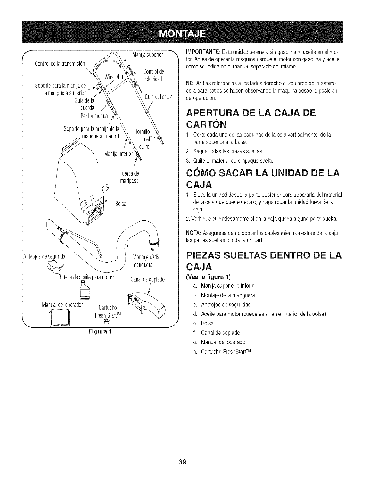
f Manijasuperior _,
Controldelatransmisi6n
Controlde
velocidad
Sopor_eparalamanijade
lamanguerasuperior Guiadelcable
Guiadela
cuerda
Perillamanual
Soporteparala manijade
manguerainferiort
Manija
Tuercade
mariposa
Bolsa
Anteojosdeseguridad
Botelladeaceiteparamotor
Manualdeloperador Cartucho
___ FreshStartTM@
Figura 1
Montaje
manguera
Canaldesoplado
,,J
IMPORTANTE:Esta unidadse enviasin gasolinani aceiteen el mo-
tor.Antesde operarla m_.quinacargueel motorcon gasolinay aceite
comose indicaenel manualseparadodel mismo.
NOTA:Las referenciasa los ladosderechoe izquierdode la aspira-
dorapara patiosse hacenobservandola maquinadesdela posicidn
de operacidn.
APERTURA DE LA CAJA DE
CARTON
1. Cortecadaunade las esquinasde lacaja verticalmente,de la
partesuperiora la base.
2. Saquetodaslas piezassueltas.
3. Quiteel materialdeempaquesuelto.
COMO SACAR LA UNIDAD DE LA
CAJA
1. Elevela unidaddesdelaparte posteriorparasepararladelmaterial
de lacaja quequededebajo,y haga rodarla unidadfuerade la
caja.
2. Verifiquecuidadosamentesi en la caja quedaalgunapartesuelta.
NOTA:AsegOresede no doblarlos cablesmientrasextraede la caja
laspartessueltaso toda la unidad.
PIEZAS SUELTAS DENTRO DE LA
CAJA
(Yea la figura 1)
a. Manijasuperiore inferior
b. Montajede la manguera
c. Anteojosde seguridad
d. Aceiteparamotor (puedeestaren el interiorde la bolsa)
e. Bolsa
f. Canalde soplado
g. Manualdel operador
h. CartuchoFreshStartTM
39
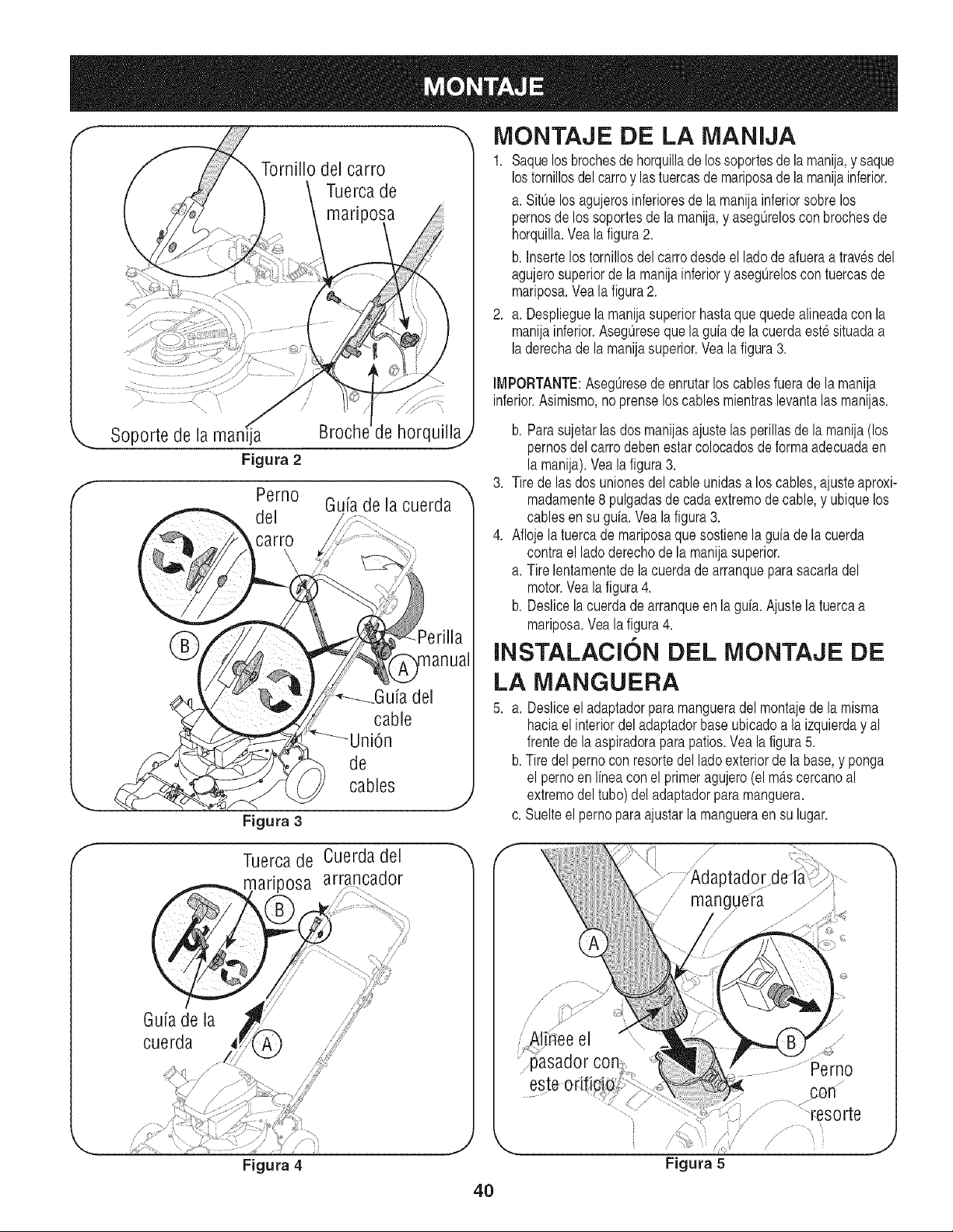
f
f
Tornillo del carro
Tuercade
mariposa
.......... L
Soporte de la man_ja
Figura 2
Perno
del
cart
Figura 3
Tuercade
_ariposa
Figura 4
Broch de horquil!a
Guiade la cuerda
de
cables
,Y
f
IVIONTAJE DE LA MANIJA
1. Saquelosbroehesde horquillade lossoportesde lamanija,y saque
lostornillosdel oarroy lastueroasde mariposade lamanijainferior.
a. SittJelos agujerosinferioresde la manijainferiorsobrelos
pernosde lossoportesde la manija,y asegOrelosconbrochesde
horquilla.Vea la figura2.
b. Insertelos tornillosdelcarrodesdeel lade de afueraa travesdel
agujerosuperiorde la manijainferiory asegOreloscontuercasde
mariposa.Vea la figura2.
2. a. Desplieguelamanijasuperiorhastaque quede alineadacon la
manijainferior.AsegOreseque la gufade la cuerdaeste situadaa
laderechade la manijasuperior.Vea la figura3.
IMPORTANTE:AsegOresede enrutarloscables fuerade la manija
inferior.Asimismo,no prenselos cablesmientraslevantalas manijas.
b. Parasujetarlas dos manijasajustelas perillasde la manija(los
pernosdelcarrodeben estarcolocadosde forma adecuadaen
la manija).Veala figura3.
3. Tire de lasdos unionesdel cable unidasa los cables,ajusteaproxi-
madamente8 pulgadasde cada extremede cable, y ubique los
cablesen su gufa. Veala figura3.
4. Aflojela tuercade mariposaque sostienela gufade la cuerda
contrael lade derechode la manijasuperior.
a. Tire lentamentede la cuerdade arranqueparasacarladel
motor.Veala figura4.
b. Deslicelacuerdade arranqueen la gufa. Ajustela tuerca a
mariposa.Vea la figura4.
INSTALACI6N DEL MONTAJE DE
LA MANGUERA
5. a. Desliceeladaptadorpara mangueradel montajede la misma
haciael interiordeladaptadorbase ubicadoa la izquierday al
frentede la aspiradoraparapatios.Yea la figura5.
b.Tire delpernoconresortedel ladeexteriorde la base,y ponga
el pernoen Ifneaconel primeragujero(el m_tscercanoal
extremedel tube)del adaptadorparamanguera.
c. Suelteelperno para ajustarla mangueraensu lugar.
Cuerdadel _,
arrancador
J
f
\
Figura 5
/.
...............................Perno
_...............:::resorte
....... i
iK
J
4O
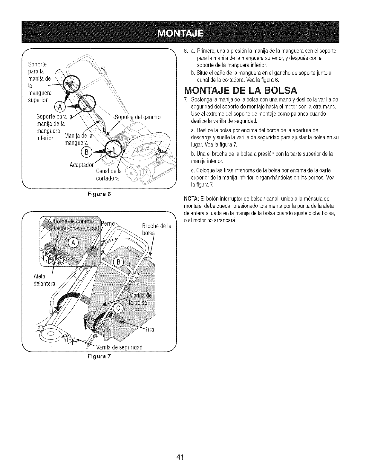
f
Aleta
delantera
delgancho
Figura 6
Broche de la
bolsa
"Tira
6. a. Primero,unaapresidnla manijade la mangueraconel soporte
parala manijade la manguerasuperior,y despuescon el
soportede la manguerainferior.
b. Sit0eel cahode la mangueraenel ganchodesoportejuntoal
canalde la cortadora.Veala figura6.
MONTAJE DE LA BOLSA
7. Sostengala manijade la bolsacon una manoy deslice la varillade
seguridaddel soportede montajehaciael motorconla otra mano.
Useel extremodel soporte de montajecomo palancacuando
deslicela varilladeseguridad.
a. Deslicela bolsapor encimadel borde de la aberturade
descargay sueltela varillade seguridadpara ajustarla bolsaen su
lugar.Veala figura7.
b. Unaelbrochede la bolsaa presidnconla partesuperiorde la
manijainferior.
c. Coloquelastirasinferioresde la bolsapor encimade la parte
superiorde la manijainferior,enganch_mdolasen lospernos.Yea
la figura7.
NOTA:El botdninterruptorde bolsa/ canal, unidoa la m_nsulade
montaje,debe quedarpresionadototalmentepor la puntade la aleta
delanterasituadaen la manijade la bolsacuandoajuste dichabolsa,
o el motornoarrancar_t.
Varillade seguridad
Figura 7
J
41
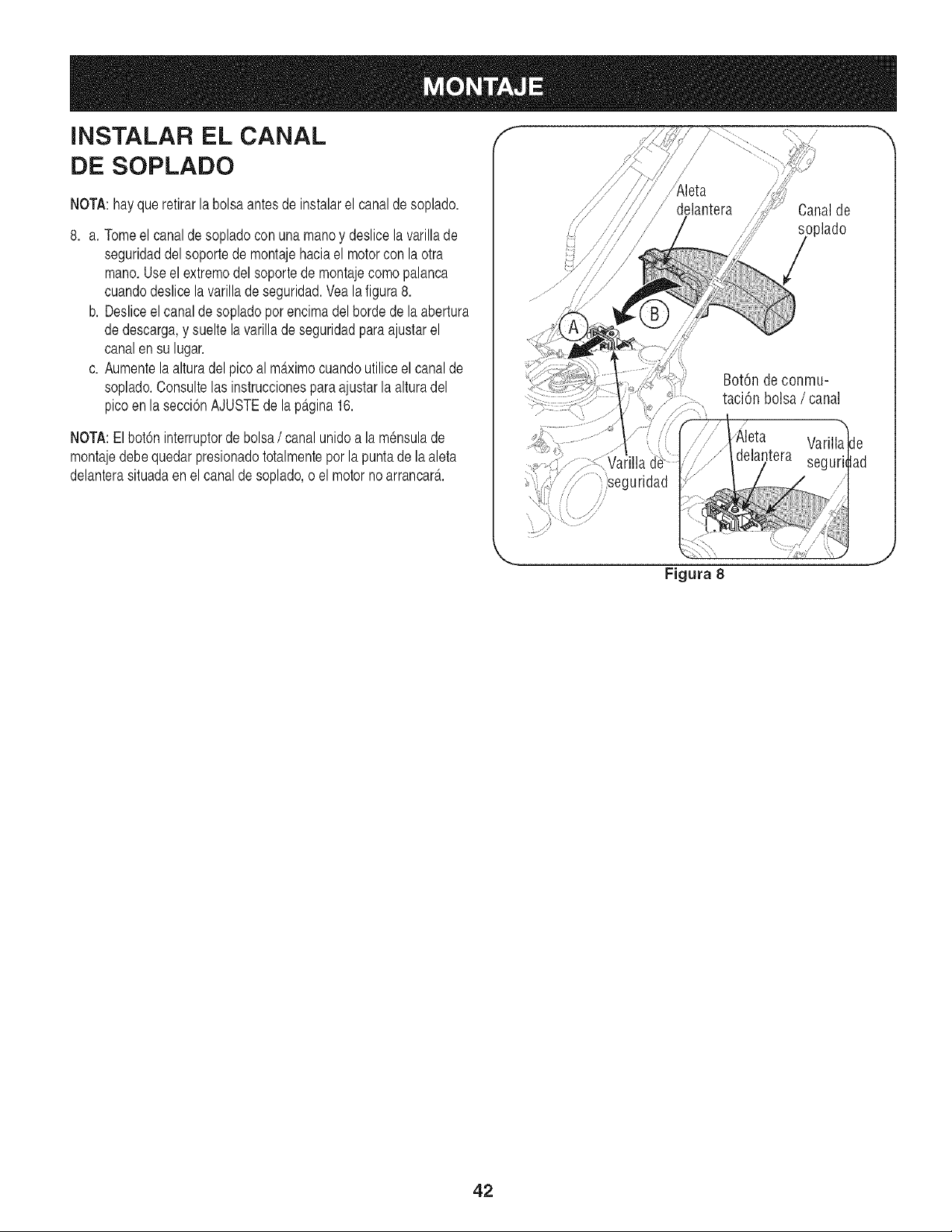
iNSTALAR EL CANAL f
DE SOPLADO
NOTA:hayqueretirarla bolsaantes de instalarel canalde soplado.
8. a. Tomeel canalde sopladocon una manoy deslice la varillade
seguridaddel soportede montajehaciael motorcon la otra
mano.Useel extremodel soportede montajecomo palanca
cuandodeslice la varillade seguridad.Vea la figura 8.
b. Desliceel canalde sopladopor encimadel borde de la abertura
dedescarga,y suelte la varillade seguridadparaajustarel
canalensu lugar.
c. Aumentela alturadelpico alm£ximocuandoutilice el canalde
soplado.Consultelas instruccionesparaajustarla alturadel
picoen la secci6nAJUSTEde lap£gina16.
NOTA:Elbot6ninterruptordebolsa/ canalunido a la m_nsulade
montajedebequedar presionadototalmentepor la puntade la aleta
delanterasituadaen el canalde soplado,o el motor no arrancar£.
Canalde
oplado
Bot6n deconmu-
taci6n bolsa / canal
)seguridad
,i
Varilla de
seguri,tad
Figura 8
J
42
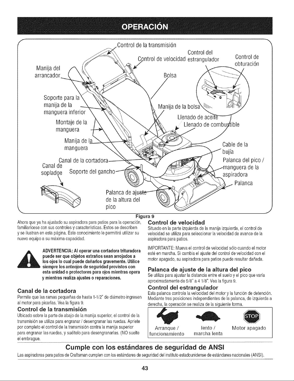
f Control de la transmisiOn
Controldel
)ntrol develocidadestrangulador
Manija del
arrancador Bolsa
Control de
obturaci6n
Soporte para la
manija de la
manguera inferior
Montaje de la
manguera
Manija de la
Llenado de
Llenado de combu
Manija de
manguera
Canalde la cortadora
Canalde
sopladoe Soporte del g
Palancade aj
de la altura del
pico
Ahoraqueya ha ajustadosu aspiradoraparapatios para la operaci6n,
familiaricesecon suscontrolesy caracteristicas.Estosse describen
y se ilustranen estap_.gina.Esteconocimientole permitirautilizarsu
nuevoequipoa su maximacapacidad.
Cablede la
bujia
Palancadel pico /
uera de la
aspiradora
Palanca
Figura 9
Control de velocidad
Situadoen la parteizquierdade la manijaizquierda,el controlde
velocidadse utilizaparaseleccionarla velocidaddeavancede la
aspiradorapara patios.
J
ADVERTENClA:AIoperar unacortadora trituradora
puedeser que objetos extraSossean arrojados a
los ojos Io cual puede daharlos gravemente.Utilice
siempre los anteojos de seguridad provistoscon
estaunidad o protectoresparaojos mientras opera
y mientras realiza ajustes o reparaciones.
Canal de la cortadora
Permiteque lasramaspequehasde hasta1-1/2"dediametroingresen
al motorparapicarlas.Veala figura9.
Control de la transmisi6n
Ubicadosobrelapartede abajode la manijasuperior,el controlde la
transmisi6nse utilizaparaengranar/ desengranarlas ruedas.Apriete
porcompletoel controlde la transmisi6ncontrala manijasuperior
paraengranarlas ruedas,y sueltelopara desengranarlas.(NOsuelte
elembrague.
IMPORTANTE:Muevael controlde velocidads61ocuandoel motor
esteen marcha.Si cambiael ajustedel controlde velocidadconel
motorapagado,su aspiradoraparapatios puederesultardahada.
Palanca de ajuste de la altura del pico
Seutilizapara ajustarla distanciaentreel sueloy el picoque varia
aproximadamentede 5/8" a 4 1/8".Vealafigura9.
Control del estrangulador
Estapalancacontrolala velocidaddel motory la funci6nde detenci6n.
Mediantetresposicionesindependientesde la palanca,de izquierdaa
derecha,la operaci6nse realizade lasiguienteforma.
Arranque / lento /
funcionamiento marcha lenta
Motor apagado
Cumple con los est_indares de seguridad de ANSI
LasaspiradorasparapatiosdeCraftsmancumplenconlosest_ndaresde seguridaddelinstitutoestadounidensede est_.ndaresnacionales(ANSI).
43
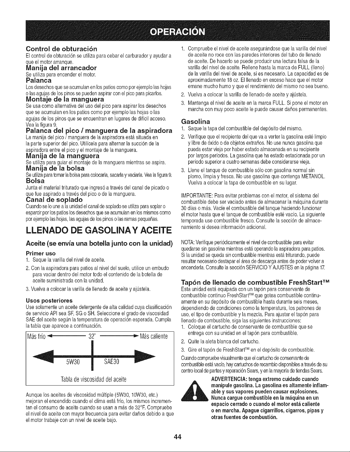
Control de obturaci6n
Elcontrolde obturaci6nse utilizapara cebarel carburadory ayudara
_e el motorarranque.
anija del arrancador
Seutiliza paraencenderel motor.
Palanca
Losdesechosqueseacumulanen lospatioscomoporejemplolashojas
o lasagujasde lospinosse puedenaspirarconelpicoparapicarlos.
Montaje de la manguera
Seusa comoalternativadel uso del picopara aspirarlos desechos
quese acumulanen los patioscomopor ejemplolas hojaso las
agujasdelos pinosque se encuentranen lugaresde dificil acceso.
Veala figura9.
Palanca del pico / manguera de la aspiradora
La manijadel pico/ manguerade la aspiradoraest,.situadaen
laparte superiordel pico. Utilicelaparaalternarla succi6nde la
aspiradoraentreel picoy el montajede la manguera.
Manija de la manguera
Seutiliza paraguiar el montajede la mangueramientrasse aspira.
Manija de la bolsa
Seutilizaparatomarlabolsaparacolocarla,sacarlay vaciarla.Vealafigura9.
Bolsa
Juntael materialtrituradoque ingres6a travesdel canalde picadoo
_e rue aspiradoa travesdel pico o de la manguera.
anal de soplado
CuandoseIounea la unidadel canaldesopladose utilizaparasoplaro
esparcirporlospatioslosdesechosqueseacumulanen losmismoscomo
porejemplolashojas,lasagujasdelospinoso lasramaspequehas.
LLENADO DE GASOLINAY ACEITE
1. Compruebeel niveldeaceiteasegur_.ndoseque la varilladel nivel
de aceiteno rocecon las paredesinterioresdel tubo de Ilenado
de aceite.Dehacerlose puede produciruna lecturafalsa de la
varilladel niveldeaceite.Rellenehasta la marcade FULL (lleno)
de la varilladel niveldeaceite,si es necesario.La capacidades de
aproximadamente18oz. El Ilenadoen excesohaceque el motor
emanemuchohumoy queel rendimientodel mismonoseabueno.
2. Vuelvaa colocar la varillade Ilenadode aceitey aj0stela.
3. Mantengael nivelde aceiteen la marca FULL.Si poneel motoren
marchacon muypocoaceitele puedecausardahos permanentes.
Gasolina
1. Saquelatapadel combustibledel dep6sitodel mismo.
2. Verifiqueque el recipientedel que vaa verterla gasolinaestelimpio
y librede6xidoo de objetosextrahos.Nouse nuncagasolinaque
puedaestarviejaporhaberestadoalmacenadaen su recipiente
porlargosperiodos.Lagasolinaque ha estadoestacionadapor un
periodosuperiora cuatrosemanasdebeconsiderarsevieja.
3. Lleneel tanquede combustibles61ocongasolinanormalsin
plomo,limpiay fresca.No usegasolinaque contengaMETANOL.
Vuelvaa colocar la tapa de combustibleen su lugar.
IMPORTANTE:Paraevitarproblemascon el motor,el sistemadel
combustibledebeser vaciadoantes de almacenarla m_.quinadurante
30 dias o m_.s.Vade el combustibledeltanquehaciendofuncionar
el motorhastaqueel tanquede combustibleeste vacio.La siguiente
temporadause combustiblefresco.Consultela secci6nde almace-
namientosi deseainformaci6nadicional.
Aceite (se envia una botella junto con la unidad)
Primer uso
1. Saquela varilladel nivelde aceite.
2. Con laaspiradoraparapatios al niveldel suelo,utilice un embudo
paravaciardentrodel motortodo el contenidode la botellade
aceitesuministradacon la unidad.
3. Vuelvaa colocarla varilla deIlenadode aceite y aj0stela.
Usos posteriores
Usesolamenteun aceitedetergentede alta calidadcuya clasificaci6n
deservicioAPIsea SF,SG o SH. Seleccioneel gradode viscosidad
SAEdel aceiteseg0nla temperaturade operaci6nesperada.Cumpla
latabla queaparecea continuaci6n.
M_sfrio _ 32° _ M_scaliente
Tabladeviscosidaddelaceite
Aunquelosaceitesdeviscosidadm01tiple(5W30,10W30,etc.)
mejoranel encendidocuandoel climaest,.frio,los mismosincremen-
tan elconsumode aceitecuandose usana m_.sde 32°RCompruebe
el niveldeaceitecon mayorfrecuenciaparaevitar dahosdebidoa que
el motortrabajecon un nivelde aceite bajo.
NOTA:Verifiqueperi6dicamenteel niveldecombustibleparaevitar
quedarsesingasolinamientrasest,.operandolaaspiradoraparapatios.
Silaunidadse quedasincombustiblemientrasest,.triturando,puede
resultarnecesariodestaparelAreadedescargaantesdepodervolvera
encenderla.Consultela secci6nSERVICIOYAJUSTESenlapagina17.
Tap6n de Ilenado de combustible FreshStart TM
Estaunidadest,.equipadaconun tap6nparaconservantede
combustiblecontinuoFreshStartTM que goteacombustiblecontinu-
amenteensu dep6sitode combustiblehastaduranteseis meses,
dependiendodecondicionescomola temperatura,los patronesde
uso,el tipode combustibley la mezcla.Paraajustarel tap6npara
Ilenadode combustible,sigalas siguientesinstrucciones:
1. Coloqueelcartuchode conservantede combustiblequese
entregaconsu unidaden el tap6n paracombustible.
2. Quite laaletablancadelcartucho.
3. Gireel tap6nde FreshStarfMen el dep6sitode combustible.
Cuandocompruebevisualmentequeel cartuchodeconservantede
combustibleest,.vacio,haycartuchosde recambiodisponiblesa travesdesu
oentrolocaldepartesy reparaci6nSears,yen lamayoriade tiendasSears.
ADVERTENCIA:tenga extremo cuidadocuando
_ anipule gasolina. La gasolina es altamenteinflam-
able y sus vaporespuedencausare×plosiones.
Nunca carguecombustible en la m_quina en un
espaciocerradoo cuandoel motor est;._caliente
o en marcha. Apaguecigarrillos,cigarros,pipasy
otras fuentes de combusti6n.
44
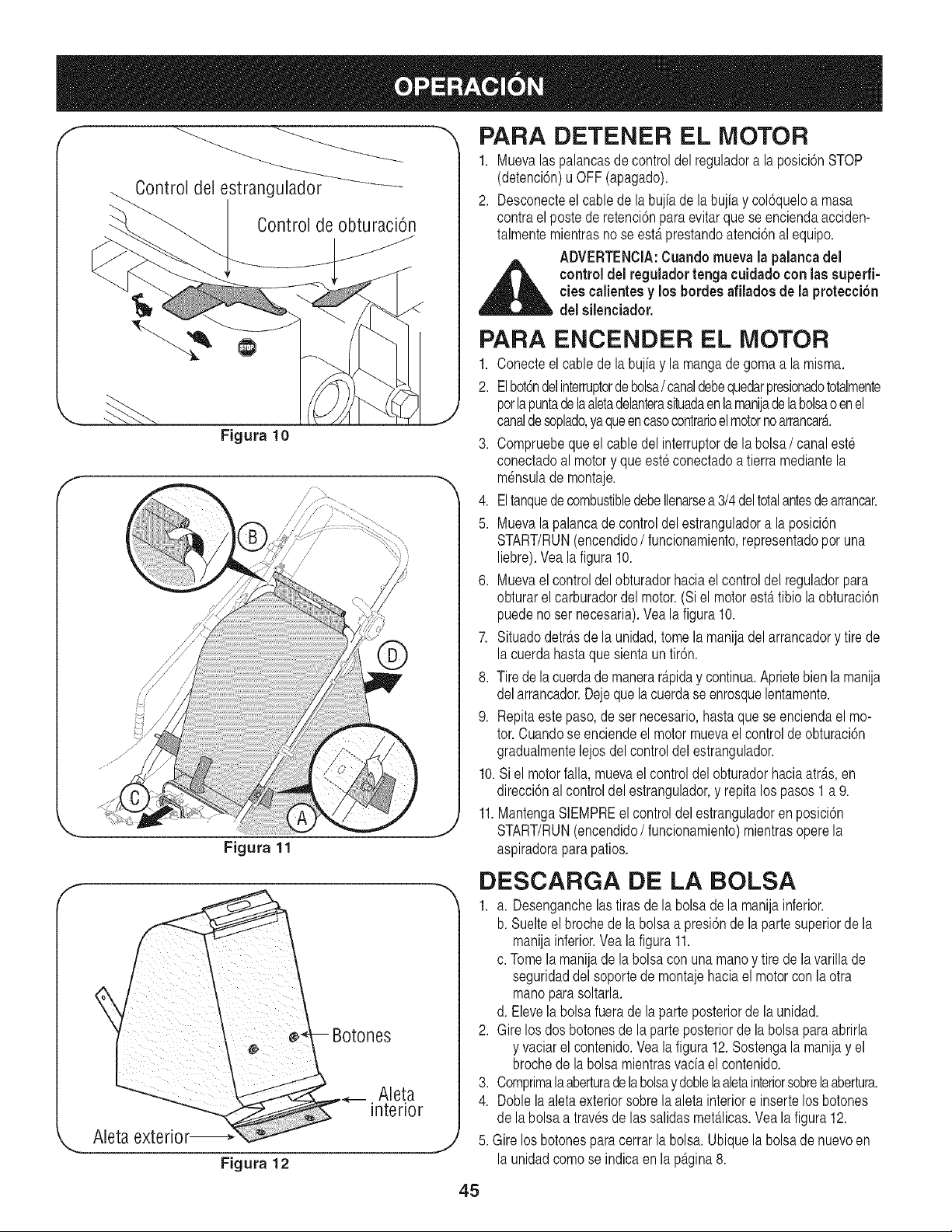
Controldelestrangulador
ControldeobturaciOn
PARA DETENER EL MOTOR
1. Muevalaspalancasde controldel reguladora laposici6nSTOP
(detenci6n)uOFF (apagado).
2. Desconecteel cablede la bujiade la bujia y col6queloa masa
contrael poste de retenci6nparaevitar que se enciendaacciden-
talmentemientrasno se est,.prestandoatenci6nal equipo.
ADVERTENClA:Cuando mueva la palancadel
_ controldel regulador tenga cuidadocon lassuperfi-
ciescalientesy los hordes afilados de la protecci6n
delsilenciador.
Figura 10
Figura 11
PARA ENCENDER EL MOTOR
1. Conecteelcablede la bujiay la mangade gomaa lamisma.
2. Elbot6ndelinterruptordebolsa/ canaldebequedarpresionadototalmente
porlapuntadela aletadelanterasituadaen lamanijadelabolsao enel
canaldesoplado,yaqueencasocontrarioel motornoarrancar_..
3. Compruebequeel cabledel interruptorde la bolsa/canal este
conectadoal motory que esteconectadoa tierramediantela
m_nsulade montaje.
4. Eltanquede combustibledebeIlenarsea 3/4del totalantesde arrancar.
5. Muevala palancade controldel estranguladora la posici6n
START/RUN(encendido/funcionamiento,representadoporuna
liebre).Veala figura 10.
6. Muevael controldel obturadorhaciael controldel reguladorpara
obturarelcarburadordel motor.(Si el motorest,.tibio la obturaci6n
puedeno ser necesaria).Veala figura10.
7. Situadodetr_.sde la unidad,tomela manijadel arrancadory tire de
la cuerdahastaquesienta un tir6n.
8. Tirede lacuerdade manerar_.piday continua.Aprietebien la manija
delarrancador.Dejeque la cuerdase enrosquelentamente.
9. Repitaestepaso, de ser necesario,hastaque se enciendael mo-
tor.Cuandose enciendeel motor muevael controlde obturaci6n
gradualmentelejosdel controldel estrangulador.
10.Siel motorfalla,muevaelcontroldelobturadorhaciaatr_.s,en
direcci6nal controldel estrangulador,y repita lospasos 1a 9.
11.MantengaSlEMPREel control del estranguladoren posici6n
START/RUN(encendido/funcionamiento)mientrasoperela
aspiradoraparapatios.
f
_,, ,J
Figura 12
DESCARGA DE LA BOLSA
1. a. Desenganchelastiras dela bolsadela manijainferior.
b. Suelteel brochede la bolsa a presi6nde la partesuperiorde la
manijainferior.Vea la figura 11.
c. Tomela manijade la bolsacon una manoy tire de lavarillade
seguridaddel soportede montajehaciael motorcon la otra
manopara soltarla.
d. Elevela bolsafuerade la parteposteriorde la unidad.
2. Girelos dos botonesde la parte posteriorde la bolsa paraabrirla
y vaciarel contenido.Vea la figura 12.Sostengala manijay el
brochede la bolsa mientrasvaciael contenido.
3. Comprimala aberturadelabolsaydoblelaaletainteriorsobrelaabertura.
4. Doble laaletaexteriorsobrela aletainteriore insertelosbotones
de labolsa atravesde lassalidasmet_.licas.Vea la figura 12.
5. Girelos botonesparacerrarla bolsa. Ubiquela bolsade nuevoen
la unidadcomose indicaen la p_.gina8.
45
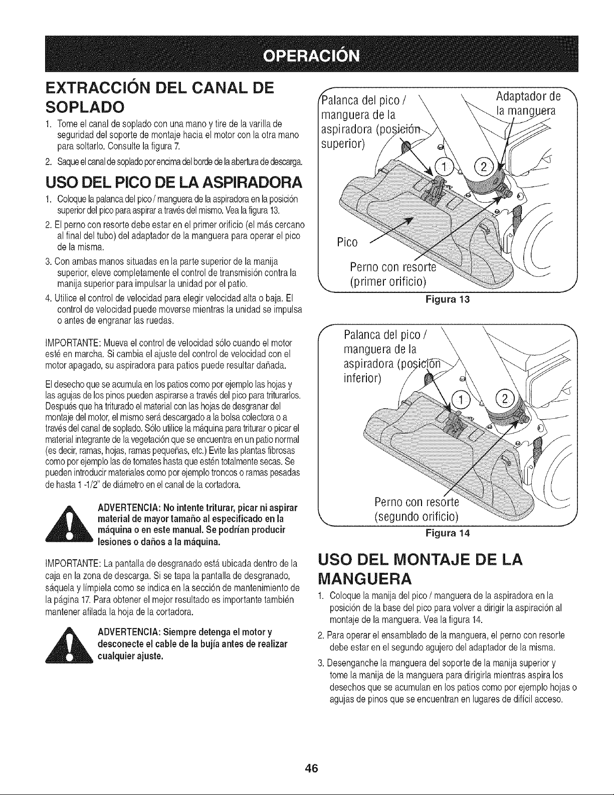
EXTRACCION DEL CANAL DE
SOPLADO
1. Tomeelcanalde sopladocon una manoy tire de la varillade
seguridaddel soportede montajehaciael motorcon la otra mano
parasoltarlo.Consultela figura7.
2. Saqueelcanaldesopladoporencimadelbordedelaaberturadedescarga.
USO DEL PICO DE LA ASPIRADORA
1. Coloquelapalancadelpico/manguerade la aspiradoraenlaposici6n
superiordel picoparaaspirara travesdelmismo.Vealafigura13.
2. Elpernocon resortedebeestar en el primerorificio (el mas cercano
alfinal deltubo) deladaptadorde la mangueraparaoperarel pico
de lamisma.
3. Con ambasmanossituadasen la partesuperiorde la manija
superior,elevecompletamenteel controlde transmisi6ncontra la
manijasuperiorpara impulsarla unidadpor el patio.
4. Utiliceelcontroldevelocidadparaelegirvelocidadalta o baja. El
controldevelocidadpuedemoversemientrasla unidadse impulsa
o antesdeengranarlas ruedas.
IMPORTANTE:Muevael controlde velocidads61ocuandoel motor
esteen marcha.Si cambiael ajustedel controlde velocidadcon el
motorapagado,su aspiradoraparapatios puederesultardahada.
Eldesechoqueseacumulaenlospatioscomoporejemplolashojasy
lasagujasde lospinospuedenaspirarsea travesdelpicoparatriturarlos.
Despuesque hatrituradoel materialconlashojasdedesgranardel
montajedelmotor,el mismoser_.descargadoa la bolsacolectoraoa
travesdelcanalde soplado.%1outilicela m_.quinaparatrituraro picarel
materialintegrantedela vegetaci6nqueseencuentraenunpationormal
(esdecir,ramas,hojas,ramaspequehas,etc.)Evitelasplantasfibrosas
comoporejemplolasdetomateshastaqueest_ntotalmentesecas.Se
puedenintroducirmaterialescomopor ejemplotroncoso ramaspesadas
dehasta1 -1/2"de di_.metroenelcanaldelacortadora.
P'_alancadel pico / Adaptador de
manguera de la la man(
aspiradora (po,,
superior)
f
Pico
Perno con resort_
(primer orificio)
Figura 13
Palanca del pico /
manguera de la
aspiradora (pc
inferior)
J
,_ ADVERTENClA:No intentetriturar, picarni aspirar
material de mayortama5o al especificado en la
m&quinao en este manual. Se podrianproducir
-- lesioneso dahosa la m_quina.
IMPORTANTE:La pantallade desgranadoestgtubicadadentrode la
cajaen la zona de descarga.Si setapa la pantallade desgranado,
s_.quelay Ifmpielacomo se indicaen la secci6nde mantenimientode
lapagina17.Paraobtenerel mejorresultadoes importantetambien
mantenerafiladalahoja de la cortadora.
_ ADVERTENClA:Siempre detenga el motor y
desconecteel cable de la bujia antes de realizar
cualquierajuste.
Pernocon resorte
(segundo orificio)
Figura 14
USO DEL IVIONTAJE DE LA
IVlANGUERA
1. Coloquelamanijadelpico/manguera de laaspiradoraen la
posici6nde labase del picopara volvera dirigir laaspiraci6nal
montajede la manguera.Vea la figura 14.
2. Paraoperarel ensambladode la manguera,el pernocon resorte
debeestar en el segundoagujerodel adaptadorde la misma.
3. Desenganchela mangueradelsoportede la manijasuperiory
tomela manijade la manguerapara dirigirlamientrasaspiralos
desechosque se acumulanen los patioscomopor ejemplohojaso
agujasde pinosquese encuentranen lugaresde dificil acceso.
46
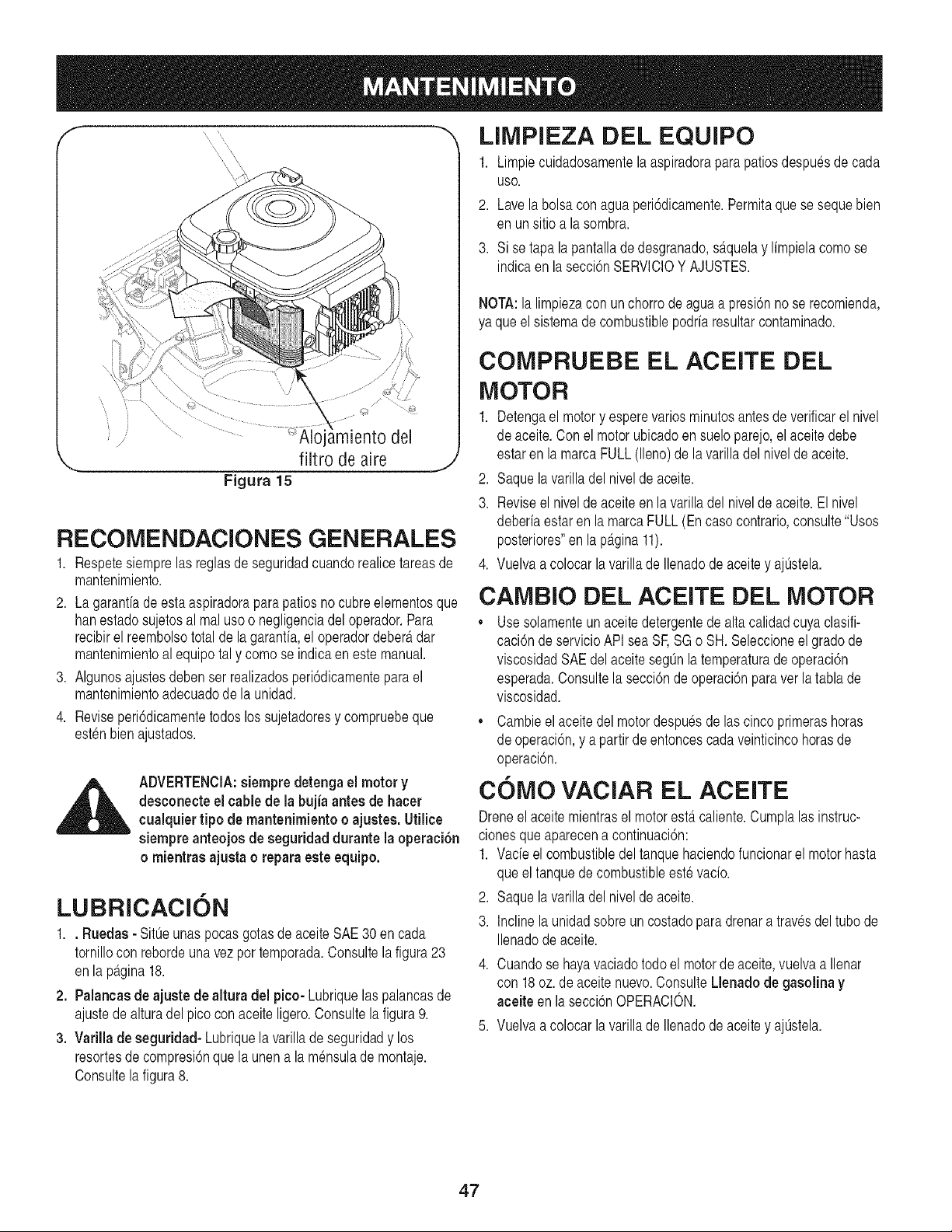
....... ............ '_,loiamiento.,j,.del
f /
/
,.... filtro de aire j
Figura 15
RECOMENDACIONES GENERALES
1. Respetesiemprelas reglasde seguridadcuandorealicetareas de
mantenimiento.
2. Lagarantfade esta aspiradoraparapatios no cubreelementosque
hanestadosujetosal real usoo negligenciadel operador.Para
recibirel reembolsototalde lagarantfa,el operadordeber_tdar
mantenimientoal equipotal y comose indicaeneste manual.
3. Algunosajustesdeben ser realizadosperi6dicamenteparael
mantenimientoadecuadode la unidad.
4. Reviseperi6dicamentetodos los sujetadoresy compruebeque
estenbienajustados.
_ DVERTENClA:siempre detengael motor y
desconecte el cable de la buj{a antes de hacer
cualquiertipo de mantenimiento o ajustes. Utilice
siempre anteojos de seguridad durante la operaci6n
o mientras ajusta o repara este equipo.
LUBRICACION
1.. Ruedas- Sit0eunaspocas gotasde aceiteSAE30 en cada
tornillocon rebordeuna vez por temporada.Consultela figura23
enla pagina18.
2. Palancasde ajuste de altura del pico- Lubriquelas palancasde
ajustede alturadel picocon aceite ligero.Consultela figura9.
3. Varilla deseguridad- Lubriquela varilladeseguridady los
resortesde compresi6nquela unena la m_nsulade montaje.
Consultela figura8.
LIMPIEZA DEL EQUJPO
1. Limpiecuidadosamentela aspiradorapara patiosdespuesde cada
USO.
2. Lave labolsacon aguaperi6dicamente.Permitaque se sequebien
en unsitio a la sombra.
3. Si se tapa lapantallade desgranado,s_.quelay limpielacomo se
indicaen la secci6nSERVlCIOY AJUSTES.
NOTA:la limpiezacon un chorrode aguaa presi6nno se recomienda,
ya queel sistemadecombustiblepodriaresultarcontaminado.
COMPRUEBE EL ACEITE DEL
MOTOR
1. Detengael motory esperevariosminutosantesde verificarel nivel
de aceite.Con el motorubicadoen sueloparejo,el aceitedebe
estaren la marca FULL(lleno)de la varilladel nivelde aceite.
2. Saquela varilladel nivelde aceite.
3. Reviseel nivelde aceiteen la varilladel nivelde aceite.El nivel
deberiaestaren la marcaFULL(En caso contrario,consulte"Usos
posteriores"en la p_.gina11).
4. Vuelvaacolocar la varillade Ilenadode aceitey ajtJstela.
CAMBIO DEL ACEITE DEL MOTOR
• Use solamenteun aceitedetergentede alta calidadcuyaclasifi-
caci6nde servicioAPIsea SF,SG o SH. Seleccioneel grado de
viscosidadSAEdelaceite segOnlatemperaturadeoperaci6n
esperada.Consultela secci6nde operaci6nparaver la tablade
viscosidad.
,, Cambieel aceitedel motordespuesde las cincoprimerashoras
de operaci6n,y a partirde entoncescadaveinticincohorasde
operaci6n.
COMO VACIAR EL ACEITE
Dreneel aceitemientrasel motorestercaliente.Cumplalas instruc-
cionesque aparecena continuaci6n:
1. Vacieel combustibledeltanquehaciendofuncionarel motorhasta
queel tanquede combustibleeste vacio.
2. Saquela varilladel nivelde aceite.
3. Inclinela unidadsobre un costadopara drenara travesdel tubode
Ilenadode aceite.
4. Cuandose hayavaciadotodoel motorde aceite,vuelva a Ilenar
con 18oz.de aceite nuevo.ConsulteLlenado de gasolina y
aceite en la secci6nOPERACION.
5. Vuelvaacolocar la varillade Ilenadode aceitey ajtJstela.
47
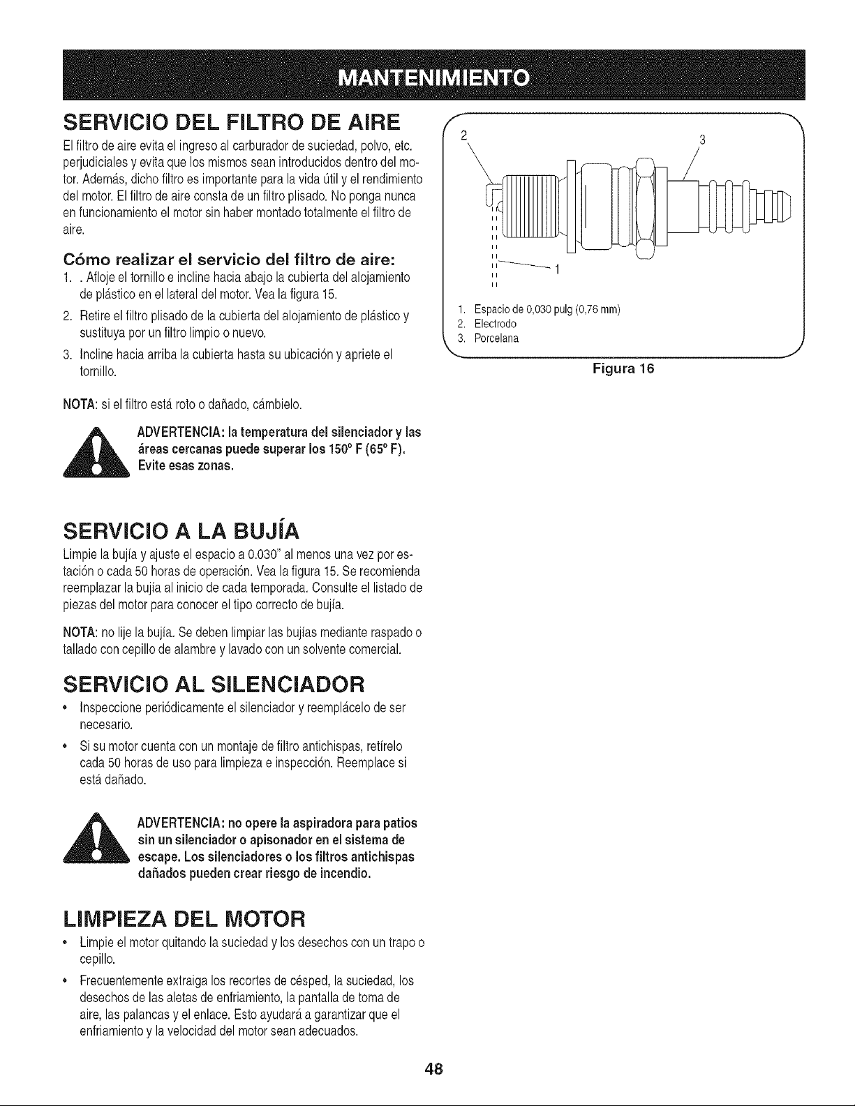
SERVlCIO DEL FILTRO DE AIRE
Elfiltrode aireevitael ingresoal carburadorde suciedad,polvo,etc.
perjudicialesy evitaque los mismosseanintroducidosdentrodel mo-
tor.Adem_.s,dicho filtroes importanteparalavida Otily el rendimiento
del motor.El filtro de aire constade un filtro plisado.No ponganunca
enfuncionamientoel motorsin habermontadototalmenteel filtro de
aire.
C6mo realizar el servicio del filtro de aire:
1.. Aflojeel tornilloe inclinehaciaabajola cubiertadel alojamiento
depl_.sticoenel lateraldel motor.Yea la figura 15.
2. Retireel filtroplisadode la cubiertadel alojamientode pl_tsticoy
sustituyapor un filtro limpioo nuevo.
3. Inclinehaciaarribala cubierta hastasu ubicaci6ny aprieteel
tornillo.
f --,,
2 3
II
II
II
II
II
II
1. Espacio de 0,030 pulg (0,76 rnm)
2. Electrodo
3. Porcelana
Figura 16
J
NOTA:si el filtro esterrotoo dahado,dtmbielo.
,_ ADVERTENClA:la temperatura del silenciador y las
_reas cercanaspuede superarlos 150° F (65° F).
Eviteesas zonas.
SERVlClO A LA BUJiA
Limpielabujiay ajusteel espacioa 0.030"al menosunavezpor es-
taci6no cada50 horasde operaci6n.Vea la figura 15.Se recomienda
reemplazarlabujiaal iniciode cadatemporada.Consulteel listadode
piezasdelmotor paraconocerel tipo correctode bujia.
NOTA:nolije labujia. Sedebenlimpiarlas bujiasmedianteraspadoo
talladoconcepillodealambrey lavadocon un solventecomercial.
SERVlClO AL SILENCIADOR
,, Inspeccioneperi6dicamenteelsilenciadory reempl_tcelode ser
necesario.
,, Si su motorcuentacon un montajede filtro antichispas,refirelo
cada50 horasde uso para limpiezae inspecci6n.Reemplacesi
esterdahado.
,_ ADVERTENClA:no opere laaspiradora parapatios
sin un silenciador o apisonador en el sistema de
escape.Lossilenciadores o losfiltros antichispas
da5adospuedencrear riesgo de incendio.
LIMPIEZA DEL MOTOR
• Limpieel motorquitandolasuciedady losdesechoscon un trapoo
cepillo.
,, Frecuentementeextraigalos recortesdecesped,lasuciedad,los
desechosde las aletasde enfriamiento,la pantallade toma de
aire,las palancasy elenlace.Esto ayudar_ta garantizarque el
enfriamientoy la velocidaddel motorseanadecuados.
48
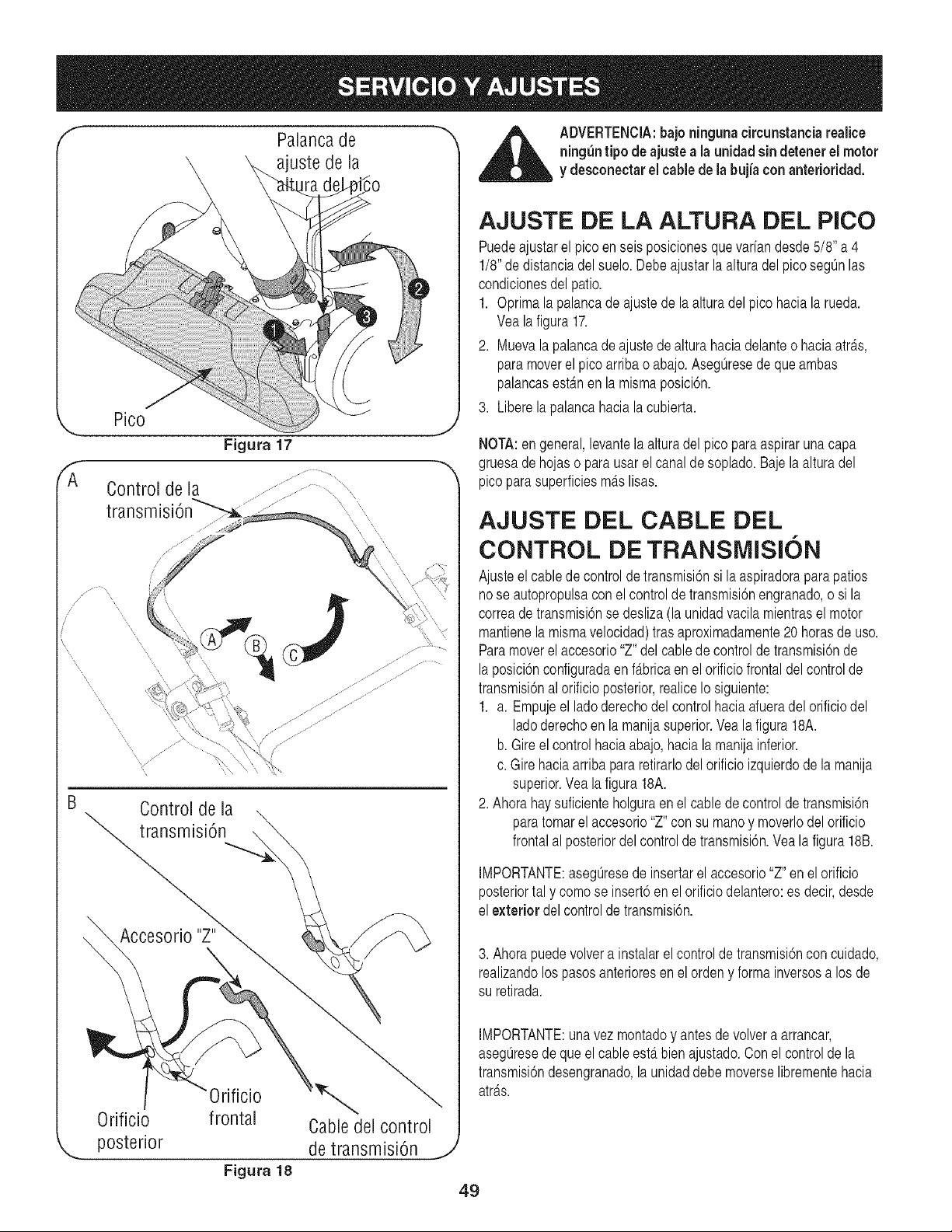
f Palancade _ _ ADVERTENCIA:bajo ningunacircunstanciarealice
ning_ntipo deajustea la unidad sin detenerel motor
ajuste de la y desconectarelcablede la bujia con anterioridad.
Pico
Figura 17
Control de la
transmisi6n
Control de la
transmisi6n
Accesorio
0rificio
posterior
0rificio
frontal
Cable del control
de transmisi6n
AJUSTE DE LA ALTURA DEL PICO
Puedeajustarel pico en seis posicionesque variandesde5/8" a 4
1/8"de distanciadelsuelo.Debeajustarlaalturadel picosegOnlas
condicionesdel patio.
1. Oprimalapalancadeajustedela alturadelpico haciala rued&
Veala figura17.
2. Muevala palancade ajustede altura haciadelanteo haciaatr_.s,
paramoverel picoarriba o abajo.AsegOresede que ambas
palancasest_tnen la mismaposici6n.
3. Liberela palancahaciala cubierta.
,J
NOTA:en general,levantela alturadel pico para aspiraruna capa
,-,, gruesade hojaso parausarel canalde soplado.Bajela alturadel
picoparasuperficiesm_.slisas.
AJUSTE DEL CABLE DEL
CONTROL DE TRANSMISION
Ajusteel cablede controlde transmisi6nsi la aspiradoraparapatios
nose autopropulsaconel controlde transmisi6nengranado,o si la
correade transmisi6nse desliza(la unidadvacila mientrasel motor
mantienela mismavelocidad)trasaproximadamente20 horasde uso.
Paramoverelaccesorio"Z" del cablede controldetransmisi6nde
laposici6nconfiguradaen fabricaen el orificio frontaldel controlde
transmisi6nal orificioposterior,realiceIo siguiente:
1. a. Empujeel lado derechodel controlhaciaafueradel orificiodel
ladoderechoen la manijasuperior.Vea la figura 18A.
b. Gireel controlhaciaabajo,haciala manijainferior.
c. Girehaciaarribapararetirarlodel orificioizquierdode la manija
superior.Veala figura18A.
2. Ahorahaysuficienteholguraen el cablede controlde transmisi6n
paratomarel accesorio"Z" con su manoy moverlodel orificio
frontalal posteriordel controlde transmisi6n.Veala figura18B.
IMPORTANTE:aseg@esede insertarel accesorio"Z" en el orificio
posteriortal y comose insert6enel orificiodelantero:es decir,desde
el exterior delcontrolde transmisi6n.
3. Ahorapuedevolvera instalarel controlde transmisi6ncon cuidado,
realizandolos pasosanterioresen el ordeny formainversosa los de
su retirada.
IMPORTANTE:unavez montadoy antesde volvera arrancar,
asegQresede queel cableest,. bienajustado.Conel controlde la
transmisi6ndesengranado,launidaddebe moverselibrementehacia
atr_ts.
Figura 18
49
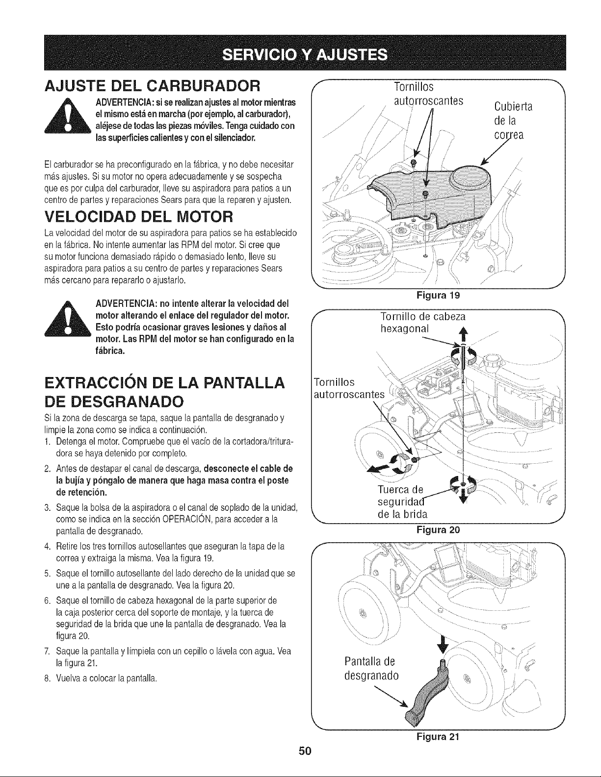
AJUSTE DEL CARBURADOR
_ DVERTENClA:si se realizanajustesal motor mientras
el mismoest;_enmarcha(pot ejemplo,al carburador),
al_jesede todas laspiezasm6viles.Tengacuidadocon
las superficiescalientesy conel silenciador.
Elcarburadorse ha preconfiguradoen la f_.brica,y no debe necesitar
m_.sajustes.Si su motorno operaadecuadamentey se sospecha
quees por culpadel carburador,Ilevesu aspiradoraparapatiosa un
centrode partesy reparacionesSearsparaque la repareny ajusten.
VELOCIDAD DEL MOTOR
Lavelocidaddel motorde su aspiradoraparapatiosse ha establecido
en lafabrica.No intenteaumentarlasRPMdel motor.Si creeque
su motorfuncionademasiador_.pidoo demasiadolento,Ilevesu
aspiradorapara patiosa su centrode partesy reparacionesSears
mAscercanopararepararloo ajustarlo.
,_ ADVERTENClA:no intentealterar la velocidad del
motor alterando el enlacedelregulador del motor.
Esto podria ocasionar graves lesionesy dahos al
motor. Las RPMdel motor se ban configuradoen la
f_brica.
EXTRACCION DE LA PANTALLA
DE DESGRANADO
Si lazonade descargase tapa,saquela pantallade desgranadoy
limpiela zonacomo se indicaa continuaci6n.
1. Detengael motor.Compruebeque el vado de la cortadora/tritura-
dorase hayadetenidopor completo.
2. Antesde destaparel canalde descarga,desconecte el cable de
la bujia y p6ngalode manera que haga masacontrael poste
de retenci6n.
3. Saquela bolsade la aspiradorao el canaldesopladode la unidad,
comose indicaen la secci6nOPERACION,paraaccedera la
pantallade desgranado.
4. Retirelos trestornillosautosellantesqueaseguranla tapade la
correay extraigala misma.Vea la figura 19.
5. Saqueel tornilloautosellantedel ladoderechode la unidadque se
unea la pantallade desgranado.Vea la figura20.
6. Saqueeltornillode cabezahexagonalde la partesuperiorde
lacaja posteriorcercadelsoporte de montaje,y la tuercade
seguridadde la bridaque une la pantallade desgranado.Vea la
figura20.
7. Saquela pantallay limpielacon un cepilloo I_.velacon agua.Vea
lafigura21.
8. Vuelvaa colocarla pantalla.
f Tornillos '_
,, autQrroscantes Cubierta
de la
/
/
co/rrea
/
/
f
Tornillo de cabeza
hexagonal _,
Tornillos
autorroscantes
\
Tuerca de
seg
de la brida
Figura 20
f
i \
Pantalla de
desgranado
5O
Figura 21
J
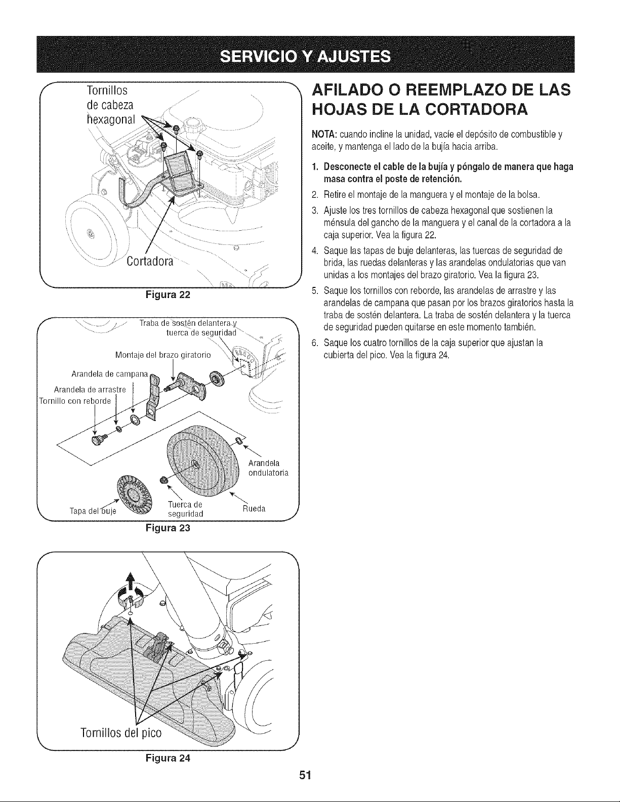
/
/
f
Tornillos
de cabeza
hexagonal
,/';:
/
Traba de _es_6n delantera_
tuerca de segu!
Montaje del brazo giratorio "
Arandela de campana
Arandela de arrastre
ornillo con reborde
Tapa
J
Arandela
ondulatoria
Tuergade
seguridad
Figura 23
Rueda
J
AFILADO O REElVIPLAZO DE LAS
HOJAS DE LA CORTADORA
NOTA:cuandoinclinela unidad,vade el dep6sitode combustibley
aceite,y mantengael lado de la bujfahaciaarriba.
1. Deeconecteel cablede la bujia y p6ngalode maneraque haga
maea contra el poetede retenci6n.
2. Retireel montajede la mangueray el montajede la bolsa.
3. Ajustelostres tornillosde cabezahexagonalquesostienenla
m_nsuladelganchode la mangueray elcanal de la cortadoraa la
caja superior.Yeala figura22.
4. Saquelastapas de bujedelanteras,lastuercasde seguridadde
brida, lasruedasdelanterasy las arandelasondulatoriasque van
unidasa los montajesdel brazogiratorio.Yea la figura23.
5. Saquelostornilloscon reborde,las arandelasde arrastrey las
arandelasde campanaque pasanpor los brazosgiratorioshasta la
trabade sostendelantera.La trabade sost_ndelanteray la tuerca
de seguridadpuedenquitarseen este momentotambien.
6. Saqueloscuatrotornillosde la cajasuperiorque ajustanla
cubiertadel pico. Veala figura24.
f
Tornillos del pico
Figura 24
,J
51
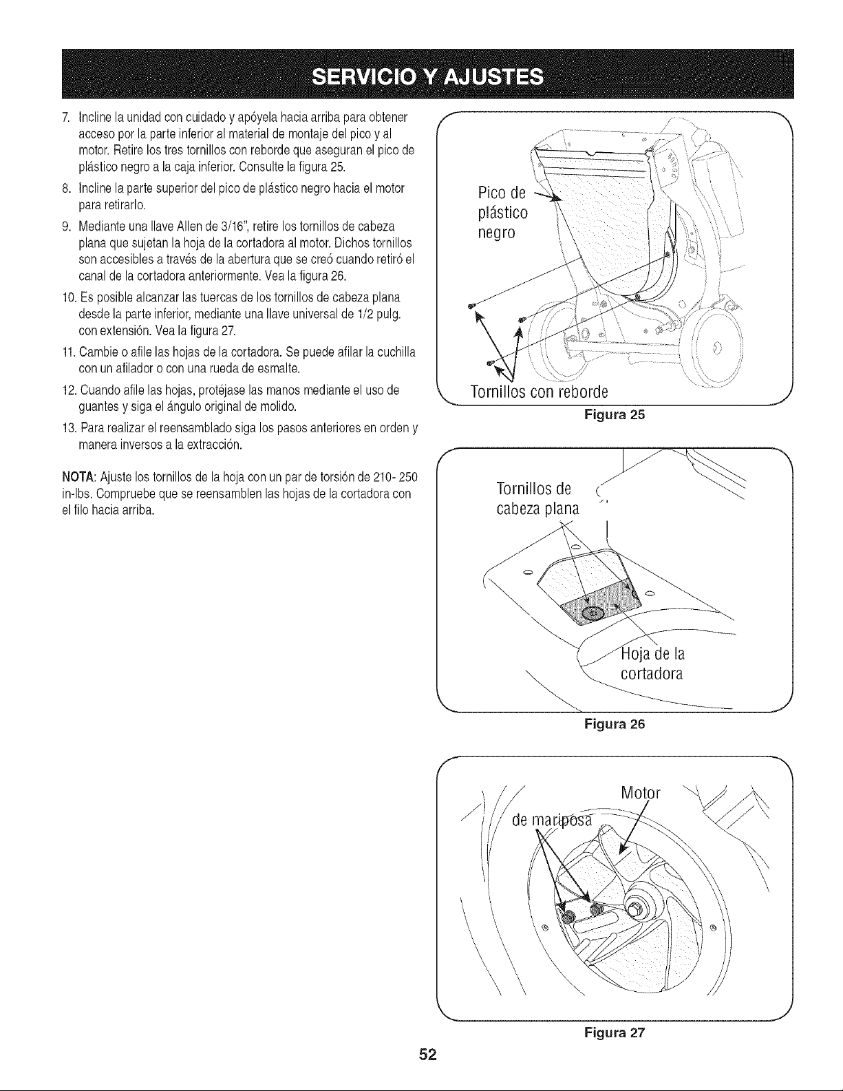
7. Inclinela unidadcon cuidadoy ap6yelahaciaarriba para obtener
accesoporla parteinferioral materialde montajedel picoy al
motor.Retirelos tres tornilloscon rebordeque aseguranel pico de
pl_tsticonegroa la caja inferior.Consultela figura25.
8. Inclinela partesuperiordel pico de pl_tsticonegro haciael motor
pararetirarlo.
9. Medianteuna IlaveAllen de 3/16",retirelostornillosde cabeza
planaquesujetanla hoja de la cortadoraal motor.Dichostornillos
sonaccesiblesatravesde la aberturaque se cre6 cuandoretir6el
canalde la cortadoraanteriormente.Vea la figura26.
10.Es posiblealcanzarlas tuercasde los tornillosdecabezaplana
desdela parteinferior,medianteuna Ilaveuniversalde 1/2pulg.
conextensi6n.Veala figura27.
11.Cambieo afilelas hojasde la cortadora.Se puedeafilarla cuchilla
con unafiladoro con una ruedade esmalte.
12.Cuandoafile las hojas,protejaselas manosmedianteel uso de
guantesy sigael _.ngulooriginalde molido.
13. Pararealizarel reensambladosiga los pasosanterioresenorden y
manerainversosa la extracci6n.
NOTA:Ajuste los tornillosde la hojaconun pardetorsi6nde 210-250
in-lbs.Compruebequese reensamblenlas hojasde la cortadoracon
elfilo haciaarriba.
negro
Tornilios con reborde
Figura 25
f
Tornillos de
cabezaplana
/i
f
Figura 26
Motor
-m
\
52
Figura 27
J
Preparela aspiradorapara patiosCraftsmanpara su almacenamiento
alfinalizarla temporada,o si nova a utilizarlaunidaddurante30
diaso m_ts.Un buenm_todoparaasegurarque launidadfuncione
adecuadamentela siguientetemporadaes realizaruna inspecci6n
anualpor partede su centro localde partesy reparacionesSears.
Aspiradora para patios
• Limpieel equipopor completo.
• Limpieel equipocon un trapo conaceite para evitarque se oxide.
Utiliceunaceiteligeroo siliconapara limpiar.
• Prepareel motorsiguiendolas instruccionesqueaparecena
continuaci6n.
• Almacenela unidaden una zona limpiay seca.No la almacene
cercade materialescorrosivoscomoporejemplofertilizantes.
Motor
Entodos loscasos,dreneel aceite del c_.rter(Ioquedeberia hacerse
tras laoperaci6ndel motor,mientrasestetodaviacaliente)y relleneel
cartercon aceitenuevo.
Cuandocompruebevisualmenteque el cartuchode conservantede
combustibleestervado, haycartuchosderecambiodisponiblesa
travesdesu centro localde partesy reparaci6nSears,yen la mayoria
de tiendasSears.
Sino utilizaFreshStartTM u otroestabilizadordecombustible,siga
estas instrucciones:
• Vacieel combustibledel tanquehaciendofuncionarel motorhasta
queel tanquede combustibleeste vado.
• Retire la bujia,vierta aproximadamente1/2 onza(una cucharada,
m_.so menos)de aceite para motoren el cilindroy de marchaal
motorlentamenteparadistribuirel aceite.
• Reemplacelabujia.
IMPORTANTE:es importanteevitarque duranteel almacenamiento
se formendep6sitosde gomaen laspiezasesencialesdel sistemade
combustible,por ejemplo,en el carburador,el filtro de combustible,la
manguerade combustibleo el dep6sito.Asimismo,los combustibles
con mezclade alcohol(que se Ilamangasohol,o que utilizanetanolo
metanol)puedenatraerla humedad,Ioque conducea la separaci6ny
formaci6nde _.cidosduranteel almacenamiento.El gasacidico puede
daharel sistemadel combustiblede un motorduranteel almace-
namientodel mismo.
NOTA:Elusode estabilizadoresde combustiblees una alternativa
aceptableal vaciadodel dep6sitode combustiblepara minimizarla
formaci6nde dep6sitosde gomade combustibleduranteel almace-
namiento.
Otros
• No almacenegasolinade una temporadaa la otra.
• Reemplaceel recipientede gasolinasi comienzaa oxidarse.La
presenciade 6xidoo polvoen la gasolinacausaproblemas.
• Almacenela unidaden una zonalimpiay seca. Nola almacene
cercade materialescorrosivoscomoporejemplofertilizantes.
NOTA:si la almacenaen ungalp6nde dep6sitomalventiladoo
met_.lico,asegOresede realizarleun tratamientoanti-oxidanteal
equipocubriendoloconaceite ligeroo silicona
Agregueel estabilizadora lagasolinaquese encuentraen
el dep6sitode combustible(siel cartuchodeconservantede
combustibleFreshStartTM estervado) o en el recipientede
almacenamiento.
No dreneel dep6sitode combustibleni el carburadorsi ester
utilizandoun estabilizadorde combustible.
53
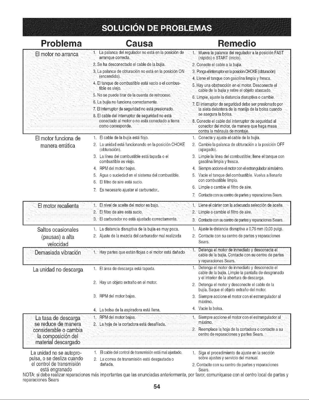
Problema
El motor no arranca
Causa Remedio
1. La palancadel regJladorno esteren la oosicionde 1. k4uevala 3alancade] regulaaora iaposici6nFAST
arranquecorrecta. (rApido)o STARTfinicioL
2. Se hadesconectadoel cable de la bujia, 2. Conecteel cable a la bulia.
3. La Daiancade obturacionno estAen la posici6nON 3. Pongaelinterruptorenlacosici6nCHOKE(obturaci6n)
(encendidoL
4. El tanqueae c )mbustible estavacio o elcombus-
tible es viejo.
5. Nose puedetirar de _acueraaae re[roceso.
6. La bu "anofuncionacorrectamen[e
7. Elinterruptorde seguridadno est#t3resionado.
8. E cable del interrt,3[orae seguridadno ester
conectadoa mo[oro no estttconectadoa tierra
comocorresoonae.
4. Lleneel tanquecon gasolina limpa y fresca.
5. Hayunaoos[rucc6n en el motor.Desconecteel
;able de la bujfay retireel objetoatascado.
6. Limpe, ajustela distanciadlsruptivao cambie.
7. Elin[errup[oraeseguridaddebe ser Dresionadooor
a aletadelameraae la man;jade la bolsacuando
se asegurala Dolsa.
8. Conecteel cable del interruptorde seguridadal
conectordel motor,ae maneraaue haga masa
contrala mensulademontae,
El rnotorfunciona de 1. Elcabledelabujiaestaflojo. 1. Conecteyajusteelcabledelabujfa.
rnanera err_.tica
2. La unidad esta funcionandoen la posici6nCHOKE
(obturaci6n).
3. La Ifnea delcombustibleestatapadao el
combustiblees viejo.
4. RPMdel motorbajas.
5. Aguao suciedaden el sistemadel combustible.
6. El filtro de aire esta sucio.
7. Es necesarioajustar el carburador..
2. Cambiela palancade obturaciona la pDsicionOFF
(apagado).
3. Limpiela Ifneadel combustible;Ileneeltanquecon
gasolinalimpiay fresca.
4. Siempreaccioneelmotorconelestranguladoralm_imo.
5. Vacie eltanquedel combustible.Vuelvaa Ilenarlo
con combustiblelimpio.
6. Limpieo cambie elfiltro deaire.
7. Contacteconsucentrodepartesy reparacionesSears.
El rnotor recalienta Elnivel de aceitedeImotores baJi: !: L!ene el carterConlaadecuadase!ecci6nde aceite,
2: El filtro de a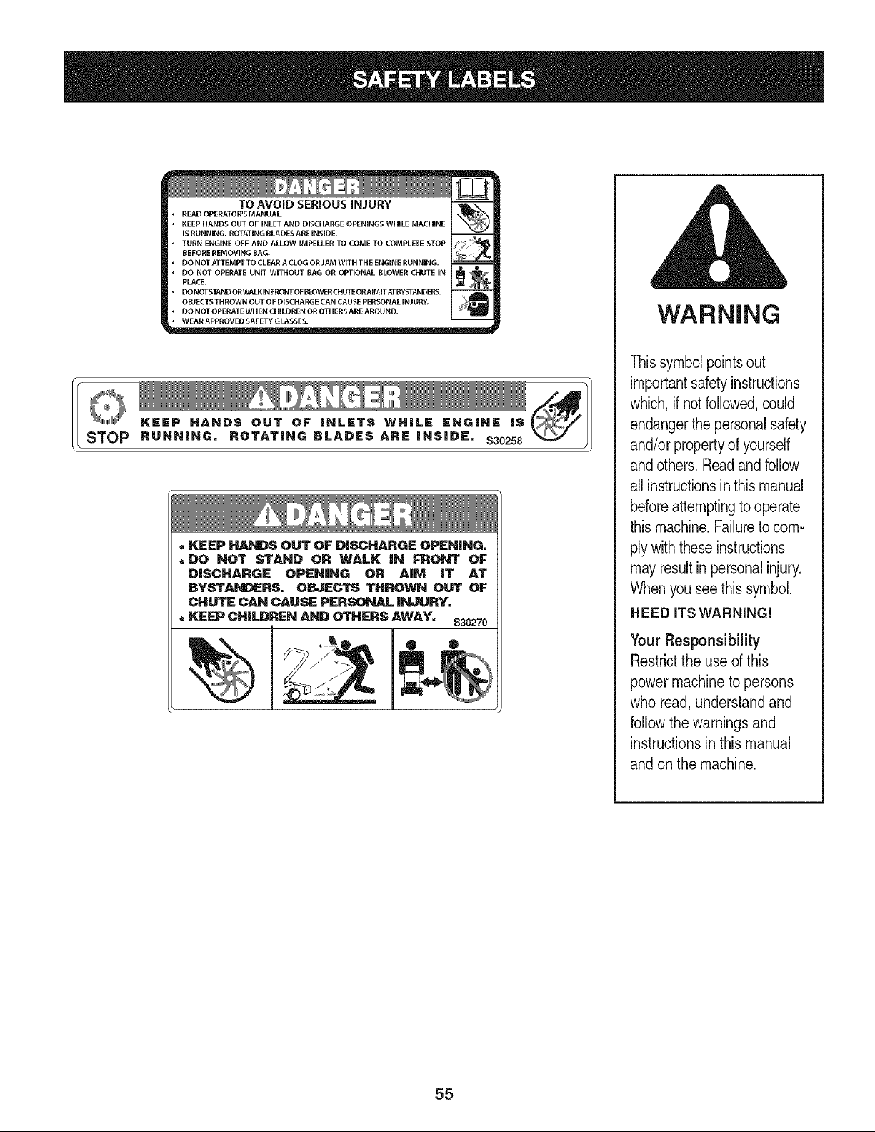
STOP
TO AVOID SERIOUS iNJURY
. READ OPERATOR'S MANUAL _
, KEEP HANDS OUT OF INLET AND DISCHARGE OPENINGS WHEE MACHINE
iS RUNNING. ROTATINGBLADESARE iNSiDE.
, TURN ENGINE OFF AND ALLOW iMPELLER TO COME TO COMPLETE STOP _
BEFORE REMOVING BAG.
, DO NOT ATTEMPTTO CLEARACLOG ORJAM WITH THE ENGINERUNNING.
" DO NOT OPERATE UNE WITHOUT BAG OR OPTIONAL BLOWER CHUTE iN IT1 _PLACE.
| o%° ss % " ||
, DONOTOPERATEWHENCHILDRENOROTHERSAREAROUND. _ _
"WEAR APPROVED SAFETY GLASSES.
• KEEP HANDS OUT OF DISCHARGE OPEN|NG.
,DO NOT STAND OR WALK |N FRONT OF
D|SCHARGE OPEN|NG OR A|M |T AT
BYSTAN_RS. O_ECTS THROWN OUT OF
CHUTE CAN CAUSE PERSONAL iNJURY.
,,KEEP DHiU)REN AND OTHERS AWAY. $30270
WARNING
This symbol points out
importantsafety instructions
which, if not followed,could
endangerthe personal safety
and/or propertyof yourself
and others. Readand follow
all instructionsin this manual
beforeattemptingto operate
this machine.Failureto com-
ply with these instructions
mayresult in personalinjury.
When you see this symbol.
HEED iTS WARNING!
Your Responsibility
Restrictthe use of this
power machine to persons
who read, understandand
follow the warnings and
instructions in this manual
and on the machine.
55
(Esta pagina se aplica s61oen EE.UU. y Canada).
Sears, Roebuck and Co., U.S.A. (Sears), el Consejo de Recursos Ambientales de California (CARB)
y la Agencia de Protecci6n Ambiental de los Estados Unidos (EPA)
Declaration de garantia del sistema de control de emisiones (derechos y obligaciones de la garantia de defectos del propi-
etario)
LA COBERTURADELA GARANTfADE CONTROLDEEMISIONESES
APLICABLEA LOS MOTORESCERTIFICADOSCOMPRADOSEN CALIFOR-
NIAEN 1995Y POSTERIORMENTE,QUE SE UTILIZANEN CALIFORNIA,
DeclaraciSn de garantia sobre defectos en el control
ElConsejode RecursosAmbientalesde California(CARB),la EPA(Agencia
de ProteccionAmbientalde los EE.UU.)y Searstienen el gustode explicarla
garantiadel sistemade control de emisionespara motoresdel a_o2000y para
elfuturo con relaciona motorespequehostodo terreno(SORE).En California,
los nuevosmotorespeque_ostodo terrenodebenestar dise_ados,construidos
y equipadosparacumplirconlas rigurosasnormasanti-smogdelestado.En
el restode losEstadosUnidos,losmotoresnuevostodoterrenode encendido
porchispacertificadosparael a_o 1997debencumplirestandaressimilares
establecidospor la EPA.Searsdebegarantizarel sistemade controlde emis-
Y PARALOS MODELOSCERTIFICADOSDELAiqO 1997Y POSTERIORES,
QUESE COMPRENY UTILICENEN CUALQUIERPARTEDE LOS ESTADOS
UNIDOS(Y A PARTIRDEL 1 DE ENERODE2001 ENCANADa,).
de emisiones para California y los Estados Unidos
ionesde su motorpara losperiodosde tiempo enumeradosa continuaci6n,
siemprequeno hayaabuso,negligenciao mantenimientoindebidode su
motortodoterrenopeque_o.Su sistemade controldeemisionespuedeincluir
piezastales comoel carburador,el filtrode aire, el sistemade encendido,el
silenciadory elconversorcatalitico.Tambienpuedeincluirconectoresy otras
unidadesrelacionadascon las emisiones.Dondeexistaunacondicioncubierta
porla garantia,Searsrepararasu peque_omotortodo terrenosincosto alguno
incluyendodiagnostico,piezasy manode obra
Cobertura de la garantia Sears para defectos en el control de emisiones
Los motorestodo terrenopeque_osestangarantizadosen Io relativoalcontrol a lasdisposicionesque se indiquena continuacion.Si una partede su motor
de emisionesparadefectosenpiezas duranteun periodode dos ahos,sujeto cubiertapor la garantiaesdefectuosa,Sears repararao sustituiradichaparte.
Responsabilidades del propietario en relacibn con la garantia
Comopropietariodel motortodo terrenopeque_o,Ud.es responsablede la
realizaciondel mantenimientorequeridoquese incluyeen las instrucciones
de operaciony mantenimiento.Sears recomiendaquese conserventodoslos
recibosrelativosal mantenimientode su motortodoterrenopeque_o,pero
no pude denegarla garantiasimplementeporla falta de los mismos,o por su
incumplimientodel mantenimientoprogramado.Comopropietariodel motor
peque_otodoterrenodebesaberque, sinembargo,Sears le puedenegar
lacoberturade lagarantiasi su motortodoterrenopeque_oo una piezadel
mismohanfalladodebidoa abuso,negligencia,mantenimientoindebidoo
a modificacionesno aprobadas.Ud.es responsablede presentarsu motor
todoterrenopequehoa un distribuidorde serviciosSearsautorizadotan pronto
comoaparezcaun problema.Lasreparacionesde la garantiasin conflicto
debencompletarseen un plazode tiempo razonable,no superiora 30 dias. Si
tienealguna preguntarespectoa sus derechosy responsabilidadesreferen-
tes a la garantia,debe contactarcon un representantede serviciosSears al
1--800--469--4663.La garantiade emisioneses unagarantiapor defectos.Los
defectossejuzgan deacuerdocon elfuncionamientonormalde un motor.La
garantia no estArelacionadacon unapruebade emisionesen uso.
Disposiciones de la garantia Sears para defectos en el control de emisiones
Las siguientesson disposicionesespecificasrelacionadascon la coberturade la garantiaparadefectosen el controlde emisiones.Esun a_adidoa lagarantiade
motorSearspara motoresnoreguladosque seencuentraen lasinstruccionesde funcionamientoy mantenimiento.
1. Piezascon garantia
La coberturade esta garantiase extiende unicamentealas piezas
que aparecena continuacion(las partesde los sistemasde controlde
emisiones),siemprequedichaspiezasestuvieranya en el motoren el
momentode su compra.
a. Sistemade medicion de combustible
,,Sistemade enriquecimientopara arranqueen frio
,,Carburadory partesinternas
• Bombade combustible
b. Sistemade induccionde aire
,,Filtrode aire
,,Colectordeadmision
c. Sistemade encendido
,,Bujia(s)de encendido
,,Sistemade encendidomagneto
d. Sistemadelcatalizador
,,Convertidorcatalitico
,,Colectordeescape
,,Sistemade inyecci6nde aireo vAIvuladeimpulsos
e. Elementosvariados usadosen los sistemasanteriores
,,VMvulasde vacio, sensiblesa temperatura,posici6ny tiempo
e interruptores
,,Conectoresy montajes
2. Alcancede la cobertura
Searsgarantiza al poseedorinicialy a los compradoressubsiguientes
que laspiezas con garantianotendran defectosen materialesni mano
de obra que provoquenla falla de las mismasduranteun periodo de
dos ahosa partirde la fecha en queel motorse entrega a un comprador
particular.
3. Sincargo
La reparaciono reemplazode cualquierpartecon garantiase realizara
sin cargo alguno parael poseedor,incluyendotareasde diagnosticoque
permitandeterminarsi una partecon garantiaes defectuosa,siempreque
dicho diagnosticose realiceen un distribuidorde serviciosSearsautoriza-
do. Parael serviciode lagarantia de emisiones,contacteal distribuidorde
serviciosSears autorizadomascercanoincluidoen las"Paginasamarillas"
en lascategoNas"Motores,gasolina","Motoresde gasolina","Podadoras
de cesped",o similares.
4. Reclamacionesy exclusionesa la cobertura
Las reclamacionesde lagarantia deben enviarsede acuerdocon las
disposicionesde la politica de garantiapara motoresSears.La cobertura
de la garantiaexcluiradefectosen piezascon garantiaque no seanpartes
originalesSears,o abuso,negligenciao mantenimientoincorrecto,tal y
como se estableceen lapolitica de garantiapara motoresSears.Searsno
es responsablede lasfallas en piezascon garantiaprovocadasporel uso
de partesa_adidas,que no sean originaleso que se hayanmodificado.
5. Mantenimiento
Cualquierpartecon garantiaque no este programadapara ser reem-
plazada comomantenimientorequerido,o que solo deba inspeccionarse
regularmenteal efectode "inspeccioneo reemplacesegt]n sea necesario",
estaragarantizadacontra defectosduranteel periodo de la garantia.Todas
las piezasgarantizadasqueesten programadaspara su reemplazopara
cumplir con los requisitosde mantenimientoestarAngarantizadassolo
por el periodoanterioral primerreemplazoprogramadopara dicha pieza.
Cualquierpiezade recambioquesea equivalenteen funcionamientoy
durabilidadpuedeusarsepara realizarmantenimientoo reparaciones.El
propietarioes responsablede realizartodo el mantenimientorequerido,tal
y como sedefine en lasinstruccionesde funcionamientoy mantenimiento
Sears
6. Coberturaindirecta
Porla presente,la coberturase extiendea lafalla de cualquiercomponente
de motorprovocadapor lafalla de unapiezacon garantia queestetodavia
en periodode garantia.
En los EstadosUnidosy Canadahay unalinea de atenci6nde 24 horas,1-800=469--4663,quecuentacon un menL_con mensajespre-grabadosquecontienen
informacionparael mantenimientode motores.