Loading ...
Loading ...
Loading ...
4. Tighten (do not overtighten) the two bolts
assembled in step 1, making sure the brace rod
is pulled tight under the large flatwasher and
against back bolt of hitch bracket. See figures
3, 4 and 5. Now tighten all other bolts assembl-
ed in steps 2 and 3.
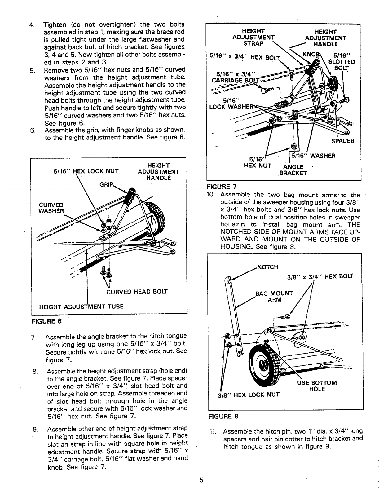
5. Remove two 5/16" hex nuts and 5/16" curved
washers from the height adjustment tube"
Assemble the height adjustment handle to the
height adjustment tube using the two curved
head bolts through the height adjustment tube.
Push handle to left and secure tightly with two
5/16" curved washers and two 5/16" hex nuts.
See figure 6.
6. Assemble the grip, with finger knobs as shown,
to the height adjustment handle" See figure 6.
5116" HEX LOCK NUT
HEIGHT
ADJUSTMENT
HANDLE
CURVED
WASHER
CURVED HEAD BOLT
HEIGHT ADJUSTMENT TUBE
FIG_,JRE 6
,
1
-9.
Assemble the angle bracket to the hitch tongue
with long leg up using one 5/t6" x 3/4" bolt.
Secure tightly with one 5/16" hex lock nut. See
figure 7.
Assemble the height adjustment strap (hole end)
to the angle bracket. See figure 7. Place spacer
over end of 5/16" x 3/4'_ stot head bolt and
into large hole on strap. Assemble threaded end
of slot head bolt through hole in the angie
bracket and secure with 5/16" lock washer and
5/16" hex nut. See figure 7.
Assemble other end of height adjus1:ment strap
to height adjustment handle, See figure 7. Place
slot on strap in line with square hole in height
adustment handle, Secure strap with 5/16" x
3/4" carriage bolt, 5/16" flat washer and hand
knob. See figure 7.
HEIGHT
ADJUSTMENT
STRAP
5116""x 314"' HEX BO
5/16" x 3/4 '°
CARRIAGE BO.LT; •
L.
5/16 "o
LOCK
HEIGHT
ADJUSTMENT
HANDLE
5/16"
SLOTTED
BOLT
FIGURE 7
10.
5/16"
HEX NUT
SPACER
5f16'" WASHER
/_NGLE
BRACKET
Assemble the two bag mount arms-to the "
outside of the sweeper housing using four 3/8"
x 3/4" hex bolts and 3/8" hex lock nuts. Use
bottom hole of dual position holes in sweeper
housing to install bag mount arm. THE
NOTCHED SIDE OF MOUNT ARMS FACE UP-
WARD AND MOUNT ON THE OUTSIDE OF
HOUSING. See figure 8.
3/8" x 3t4'" HEX BOLT
3f8" HEX LOCK NUT
USE BOTTOM
HOLE
FIGURE 8
1_]. Assemble the hitch pin, two_l '' dia. x 3/4" tong
spacers and hair pin cotter to hitch bracket and
hitch tongue as shown in figure 9.
5
Loading ...
Loading ...
Loading ...