Loading ...
Loading ...
Loading ...
PAGE: 7 / 12 PAGE: 8 / 12
ASSEMBLY INSTRUCTIONS (continued) ASSEMBLY INSTRUCTIONS (continued)
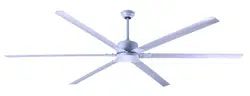
3. ELECTRICAL HOOK-UP
B
- Place two screws and washers on mounting plate (marked B on diagram) which
correspond with slots in canopy. Screw in two turns.
- Position canopy to mounting plate aligning slots to screws (marked B on diagram)
then turn to lock.
- Position and tighten the two screws and washers (marked A on diagram) then tighten
the two screws (marked B on diagram).
4. MOUNTING FAN ASSEMBLY
NOTE: Once wires are connected, carefully tuck wires and wire nuts into the
outlet box making sure that the wires are clear of the hemisphere
and downrod when positioned in mounting bracket
(Downrod Mount Only).
CONNECTING BLACK,WHITE,AND (RED OR BLUE) WIRES
Black Wire
White Wire
C
5. ENGAGE HEMISPHERE (Downrod Mount Only)
- Carefully rotate fan assembly until groove in hemisphere locks over tab of canopy assembly.
WARNING: Failure to seat tab in groove could cause damage to electrical wires and
possible shock or fire hazard.
Downrod
Hemisphere
Groove
NOTE: When installing fan on sloped ceiling, make sure tab on hanger bracket faces towards
the top of the slope. Depending on the slope, a longer downrod may be required to prevent
fan blades from hitting the ceiling.
a.
b.
(A)
(B)
(B)
Washers
(A)
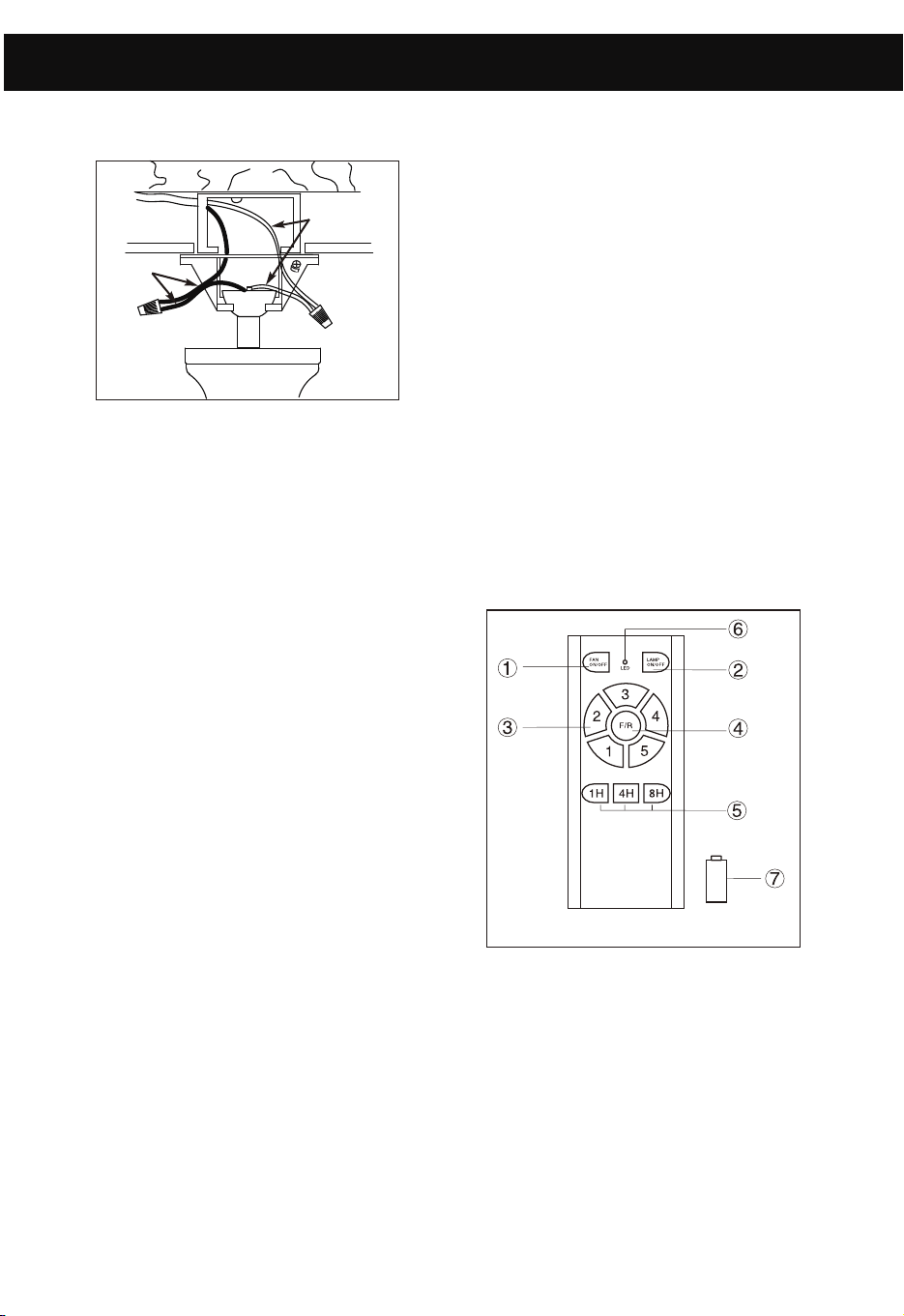
FUNCTION INSTRUCTION OF EMITTER
- Learning code and matching mode is used between transmitter and receiver.
- Turn "ON" the supply power. Within 30 seconds, press "FAN ON/OFF" button on
the transmitter for 5 seconds. Transmitter
and receiver are connected after hearing
a long “beep".
- If the transmitter cannot control the fan,
check to ensure all wiring connections are
properly connected according to the
instruction manual. Check to ensure the
batteries are in the right position. Check
whether there are any similar remote
controls in use nearby. Check whether
they work with the same frequency.
- Low voltage of battery will affect the
sensitivity of the transmitter. The
indicator light (6) will flash when battery
voltage is low. Replace the batteries for better performance.
- Take out the batteries from the transmitter when leaving unused for long periods.
- Ensure to connect the ground wire accordingly
- Connect white wire from outlet box to white
wire from fan using wire nut (not supplied).
- Connect black wire from outlet box to black
wire from fan using a wire nut (not supplied).
3. ELECTRICAL HOOK-UP
D
INSTALLING THE REMOTE CONTROL WALL BRACKET
If desired, the wall bracket can be installed
to house the remote control.
- Use the screws to secure the wall
bracket at the desired mounting location.
- Place the remote control into the wall
- Mount the cap onto the top of remote
control as shown by the 2 screws if
necessary.
bracket.
Wall bracket
Screw
Remote control
Cap
Screw
b.
c.
d.
Loading ...
Loading ...
Loading ...