Dunstabzug
Hotte d’aspiration
Cappa aspirante
Range hood
DEHMR 5/7/8
Betriebsanleitung
Mode d’emploi
Istruzioni per l’uso
Operating instructions
V-ZUG AG
2
2
INHALTSVERZEICHNIS
SICHERHEITSINFORMATIONEN........................................................................................................................................... 3
CHARAKTERISTIKEN........................................................................................................................................................... 6
MONTAGE ............................................................................................................................................................................. 7
BEDIENUNG.......................................................................................................................................................................... 9
REINIGUNG UND WARTUNG............................................................................................................................................... 10
SOMMAIRE
CONSIGNES DE SÉCURITÉ................................................................................................................................................. 12
CARACTERISTIQUES......................................................................................................................................................... 15
INSTALLATION.................................................................................................................................................................... 16
UTILISATION ....................................................................................................................................................................... 18
NETTOYAGE ET ENTRETIEN .............................................................................................................................................. 19
INDICE
INFORMAZIONI SULLA SICUREZZA.................................................................................................................................... 21
CARATTERISTICHE............................................................................................................................................................ 24
INSTALLAZIONE ................................................................................................................................................................. 25
USO...................................................................................................................................................................................... 27
PULIZIA E MANUTENZIONE................................................................................................................................................. 28
INDEX
SAFETY INFORMATION....................................................................................................................................................... 30
CHARACTERISTICS ........................................................................................................................................................... 33
INSTALLATION.................................................................................................................................................................... 34
USE ...................................................................................................................................................................................... 36
CARE AND CLEANING......................................................................................................................................................... 37
DE
FR
IT
EN

DE
3
3
SICHERHEITSINFORMATIONEN
Zu Ihrer eigenen Sicherheit und für die korrekte Funktion des Gerätes
lesen Sie bitte diese Betriebsanleitung aufmerksam durch, bevor Sie das
Gerät installieren und benutzen. Verwahren Sie die Bedienungsanleitung
stets zusammen mit dem Gerät, auch wenn Sie dieses an Dritte
weitergeben oder übertragen. Es ist wichtig, dass der Benutzer alle
Betriebs- und Sicherheitsmerkmale des Gerätes kennt.
Die Kabel müssen von einem zuständigen Fachmann angeschlossen
werden.
x Der Hersteller haftet nicht für etwaige Schäden, die durch eine fehlerhafte
Installation oder einen ungeeigneten Gebrauch entstehen könnten.
x Der min. Sicherheitsabstand zwischen Kochfeld und Abzugshaube
beträgt 650 mm (einige Modelle können auch niedriger installiert werden;
siehe Absatz Installation).
x Sollten die Installationsanweisungen des gasbetriebenen Kochfelds einen
größeren Abstand als oben angegeben vorsehen, ist dies zu
berücksichtigen.
x Sicherstellen, dass die Netzspannung der auf dem Typenschild
angegebenen Spannung entspricht. Das Typenschild ist im Inneren der
Haube angebracht.
x Trennvorrichtungen müssen in der festen Anlage gemäß Normen über
Verkabelungssysteme installiert werden.
x Für Geräte der Klasse I sicherstellen, dass das Versorgungsnetz des
Gebäudes korrekt geerdet ist.
x Die Abz
ugshaube an den Schornstein mit einem Ro
hr mit
Mindestdurchmesser von 120 mm anschließen. Der Verlauf des
Rauchabzugs muss so kurz wie möglich sein.
x Alle gesetzlichen Vorschriften im Bereich Abluft einhalten.
x Die Abzugshaube darf nicht an einen Schacht angeschlossen werden, in
den Rauchgase abgeleitet werden (z. B. von Heizkesseln, Kaminen,
usw.).

DE
4
4
x Falls die Abzugshaube mit Geräten verwendet wird, die nicht elektrisch
betrieben sind (z.B. Gasgeräte), muss im Raum für eine ausreichende Belüftung
gesorgt werden, damit der Rückfluss der Abgase verhindert wird. Wird die
Abzugshaube zusammen mit nicht elektrisch betriebenen Geräten eingesetzt,
darf der Unterdruck im Raum 0,04 mbar nicht überschreiten, damit die Abgase
nicht wieder angesaugt werden.
x Die Luft darf nicht durch einen Kanal abgelassen werden, der als Rauchabzug
für Gasgeräte oder Geräte verwendet wird, die mit anderen Brennstoffen
betrieben werden.
x Wenn das Gerätekabel beschädigt ist, muss es
vom Hers
teller oder von einem
Kundendiensttechniker ersetzt werden.
x Den Stecker in eine den einschlägigen Vorschriften entsprechende zugängliche
Steckdose stecken.
x Was die technischen und sicherheitsrelevanten Maßnahmen für den
Rauchabzug betrifft, sind die Vorgaben der örtlichen Behörden streng
einzuhalten.
WARNUNG: Bevor die Haube installiert wird, die Schutzfolien abziehen.
x Nur für die Abzugshaube geeignete Schrauben und Kleinteile verwenden.
WARNUNG: Die mangelnde Verwendung von Schrauben und
Befestigungselementen gemäß der vorliegenden Anleitung kann zu
Stromschlaggefahr führen.
x Nicht direkt mit optischen Instrumenten (Fernglas, Lupe, usw.) in das Licht
schauen.
x Auf keinen Fall unter der Haube flambieren: Dabei könnte ein Brand entstehen.
x Dieses Gerät darf von Kindern ab 8 Jahren und von Personen mit beschränkten
geistigen, physischen oder sensorischen Fähigkeiten oder mangels Erfahrung
und/oder mangels Wissen benutzt werden, vorausgesetzt, sie werden
aufmerksam beaufsichtigt oder über
den sicheren Gebrauch des Ge
räts und die
damit verbundenen G
efahren eingewiesen. Sicherstellen, dass Kinder
nicht mit
dem Gerät spielen. Vom B
enutzer auszuführende Reinigungs-
und
Wartungsarbeiten dür
fen nicht von Kindern ausgeführt we
rden, sofern sie nicht
dabei beaufsichtigt werden.
x Kinder müssen beaufsichtigt werden, damit sichergestellt wird, dass sie nicht am
Gerät spielen.
DE
5
5
x Dieses Gerät darf nicht von Personen (einschließlich Kindern) mit
beschränkten geistigen, physischen oder sensorischen Fähigkeiten oder
mangels Erfahrung und/oder mangels Wissen benutzt werden, außer sie
werden aufmerksam beaufsichtigt und eingewiesen.
Die frei zugänglichen Teile können während des Kochens mit
Kochgeräten sehr heiß werden.
x Die Filter sind nach den angegebenen Intervallen zu reinigen und/oder zu
ersetzen (Brandgefahr). Siehe Absatz Wartung und Reinigung.
x Wenn die Abzugshaube gleichzeitig mit Geräten verwendet wird, die Gas
oder andere Brennstoffe benutzen, muss im Raum eine ausreichende
Belüftung vorhanden sein (gilt nicht für Geräte, die nur Luft in den Raum
ablassen).
x Schutzschild bei Rissbildung ersetzen. Das Symbol
am Produkt oder
auf der Verpackung weist darauf hin, dass das Gerät nicht als normaler
Hausmüll entsorgt werden darf. Das ausrangierte Gerät muss vielmehr
bei einer speziellen Sammelstelle für elektrische und elektronische Geräte
abgegeben werden. Mit der vorschriftsmäßigen Entsorgung des Gerätes
trägt der Benutzer dazu bei, schädliche Auswirkungen auf Umwelt und
Gesundheit zu vermeiden. Weitere Informationen zum Recycling dieses
Produktes können bei der zuständigen Behörde, der örtlichen
Abfallbeseitigung oder bei dem Händler, der das Gerät verkauft hat,
eingeholt werden.
DE
6
6
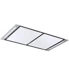
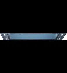
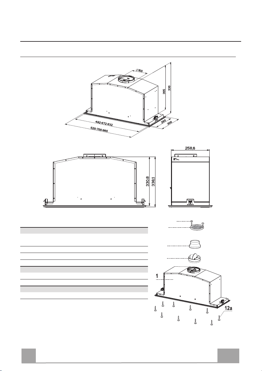
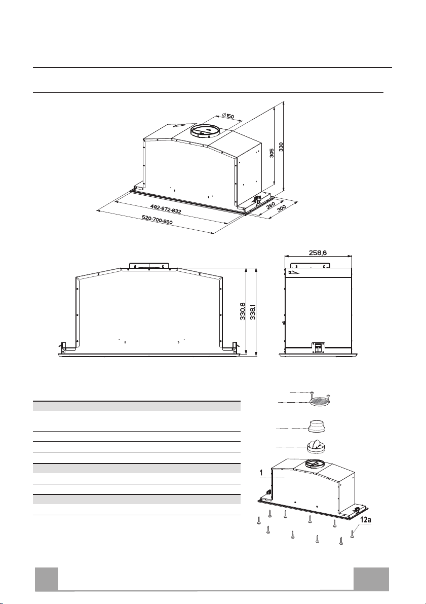
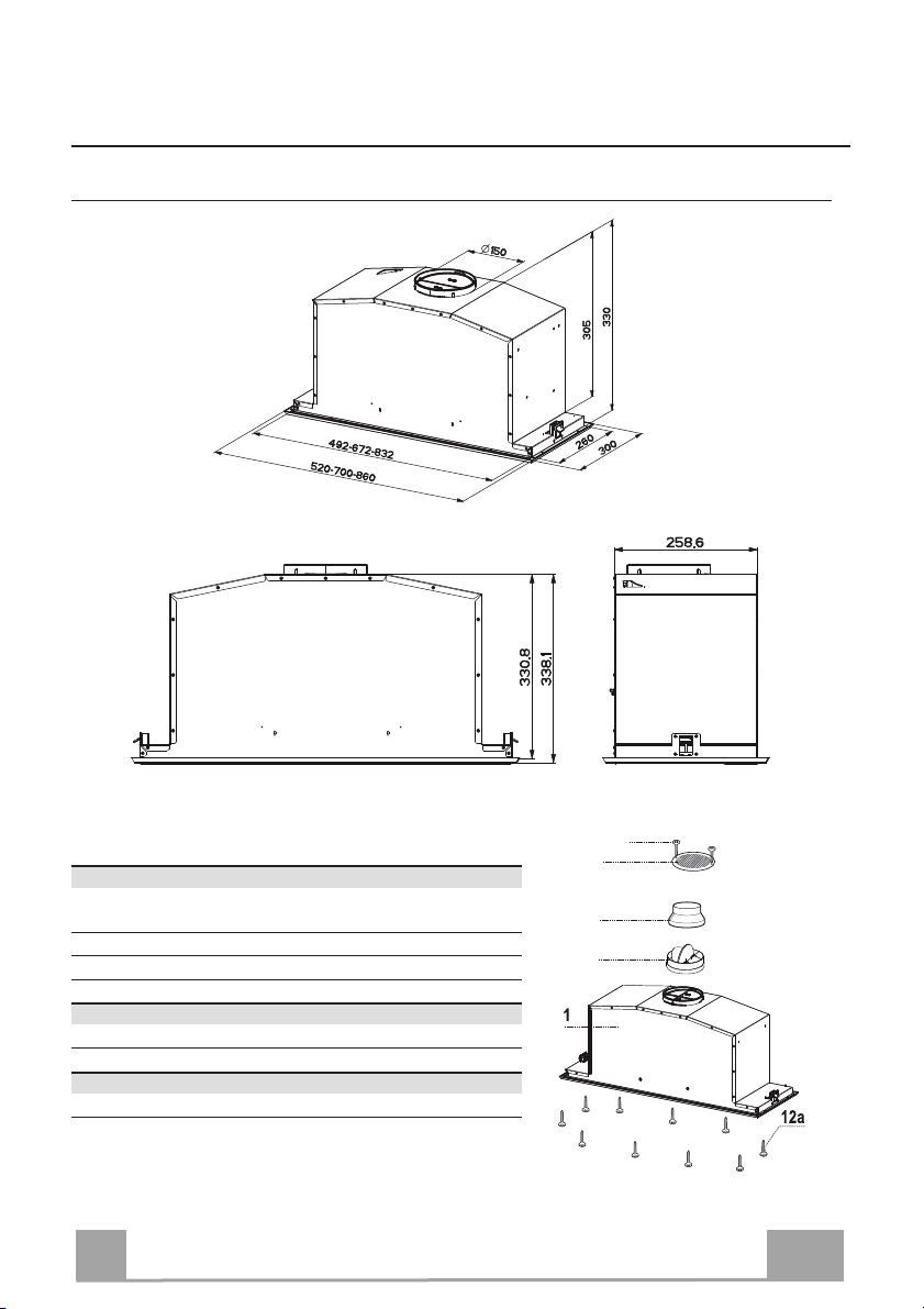
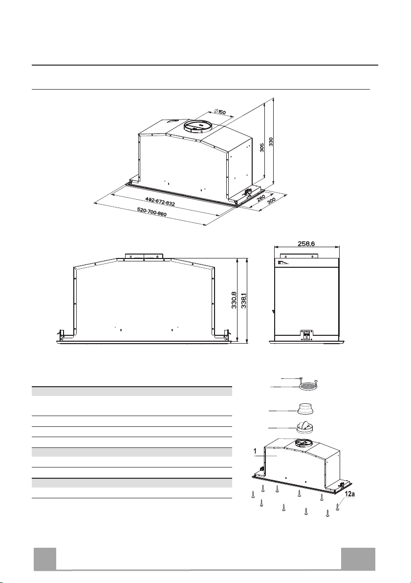
CHARAKTERISTIKEN
Platzbedarf
Komponenten
Bez. Menge Produktkomponenten
1 1 Haubenkörper komplett mit: Bedienelemente, Beleuch-
tung, Filter, Absaugeinheit
8 1 Luftstromrichtungsgitter
9 1 Reduzierflansch ø 150-120 mm
10 1 Flansch mit Ventil ø 150 mm
Bez. Menge Produktkomponenten
12a 10 Schrauben
12e 2 Schrauben 2,9 x 9,5
Menge Unterlagen
1 Betriebsanleitung
10
9
8
12e
DE
7
7
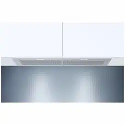
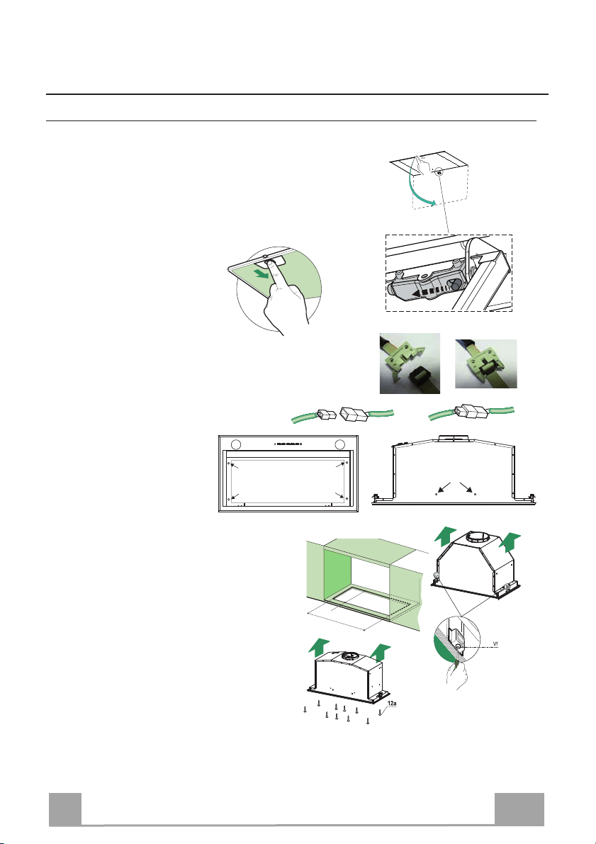
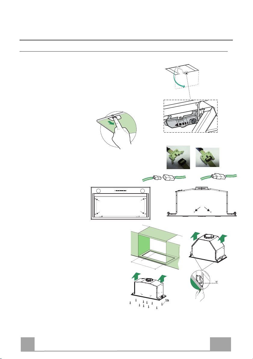
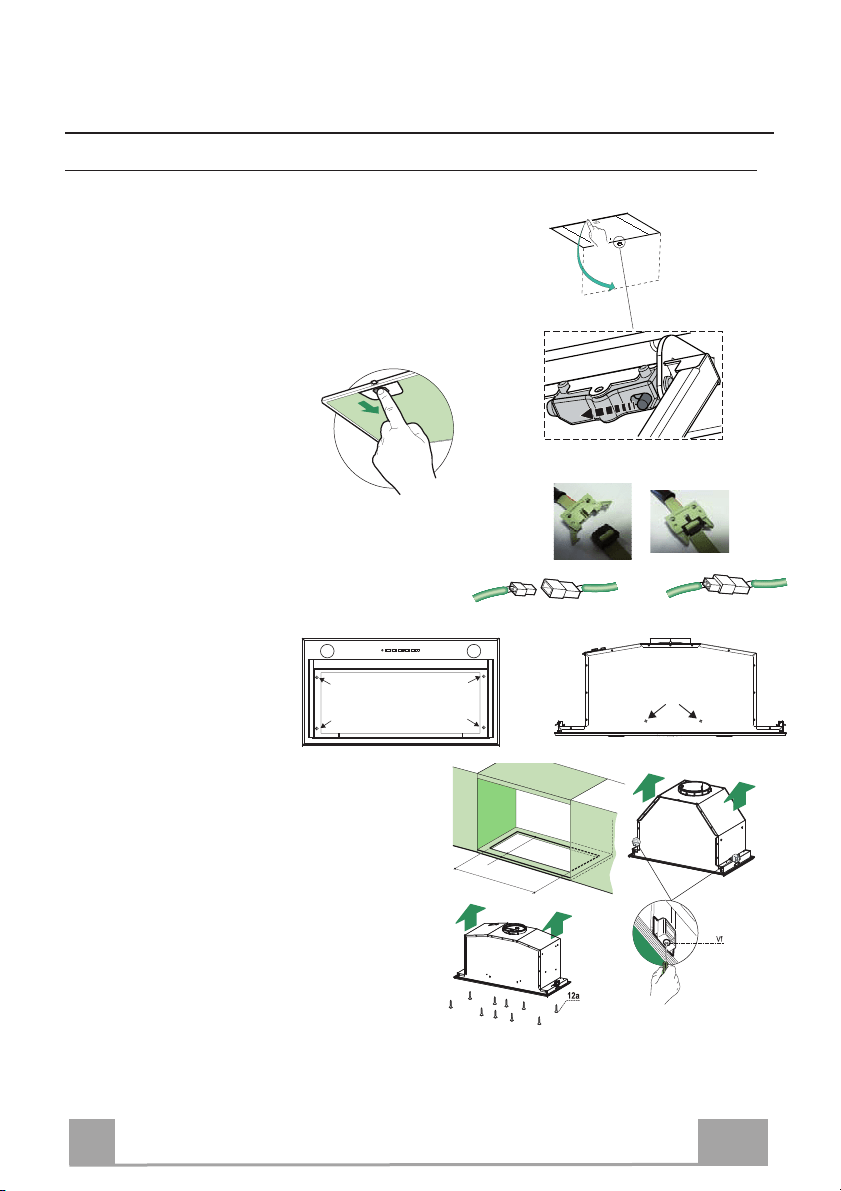
MONTAGE
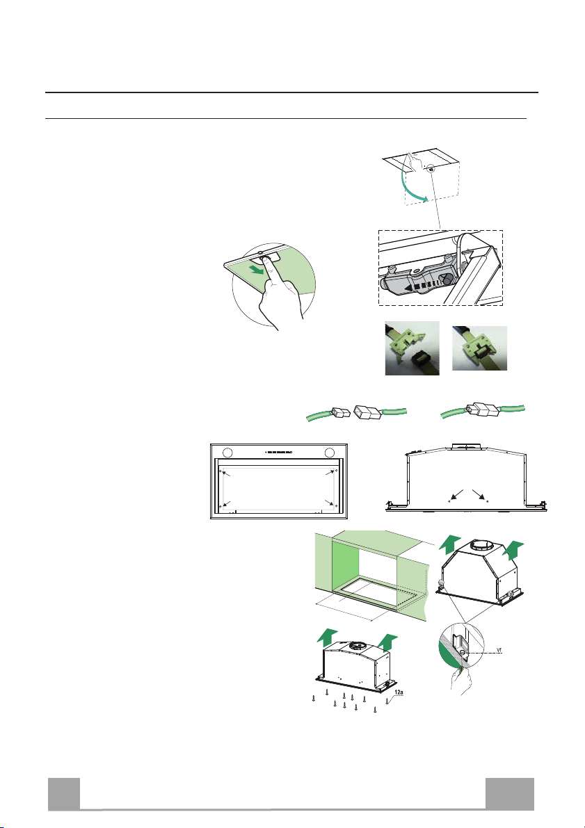
Montage des Haubenkörpers
BEVOR DIE HAUBE AM HÄNGESCHRANK MONTIERT WIRD, WIE FOLGT VORGEHEN:
• Das Absaugpaneel herausziehen.
•
Das Paneel vom Haubenkörper lösen, in dem der spezielle
Hebel des Befestigungszapfens verschoben wird.
• Die Fettfilter entfernen.
• Die Drähte der Bedienelemente abhängen, indem die Verbinder
gelöst werden.
• Die Drähte der Beleuchtung abhängen, indem die
Verbinder gelöst werden.
• Den Rahmen durch
Aufschrauben d
er 6
Schrauben ausbauen.
• Die Haube kann direkt an der Unterseite des
Hängeschranks
angebracht werden min. (650
mm von der Kochfläche).
• An der Unterseite des Hängeschranks eine
Aussparung anfertigen, wie abgebildet.
• Die Haube einsetzen und die seitlichen
Halterungen einhaken.
• Mit den 10 mitgelieferten Schrauben 12a
befestigen.
• Durch Festschrauben von unten der Schrauben
Vf definitiv blockieren.
• Den Rahmen mit den 6 zuvor entfernten Schrauben wieder befestigen, die Drähte der
Bedienelemente und der Beleuchtung wieder anschließen, den Fettfilter und das Paneel
wieder einbauen.
0
260
13
495 - 675 -835
DE
8
8
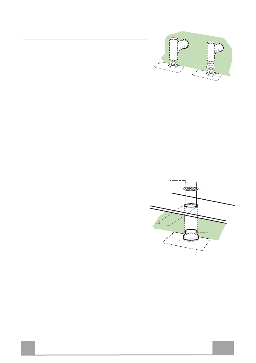
Anschluss
Anschluss Im Abluftbetrieb
Bei Abluftbetrieb kann die Haube vom Installateur wa-
hlweise mittels Rohr oder Schlauch (ø150 oder 120mm)
an die Außenrohrleitung angeschlossen werden.
Anschlussrohres ø 150
• Den Flansch mit Ruckstauklappe 10 anbringen.
• Das Rohr mit geeigneten Rohrschellen fixieren.Das
hierzu erforderliche Material wird nicht mitgeliefert.
Anschlussrohres ø 120
• Bei Verwendung eines Anschlussrohres ø 120 den
Reduzierflansch 9 am Flansch mit Ruckstauklappe
10 anbringen.
• Das Rohr mit geeigneten Rohrschellen fixieren.Das
hierzu erforderliche Material wird nicht mitgeliefert.
• Eventuell vorhandene Aktivkohlefilter entnehmen.
ø 120
ø 150
10
10
9
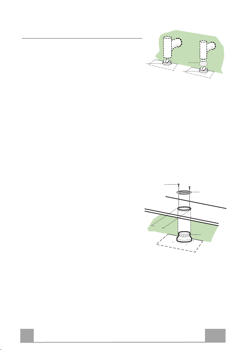
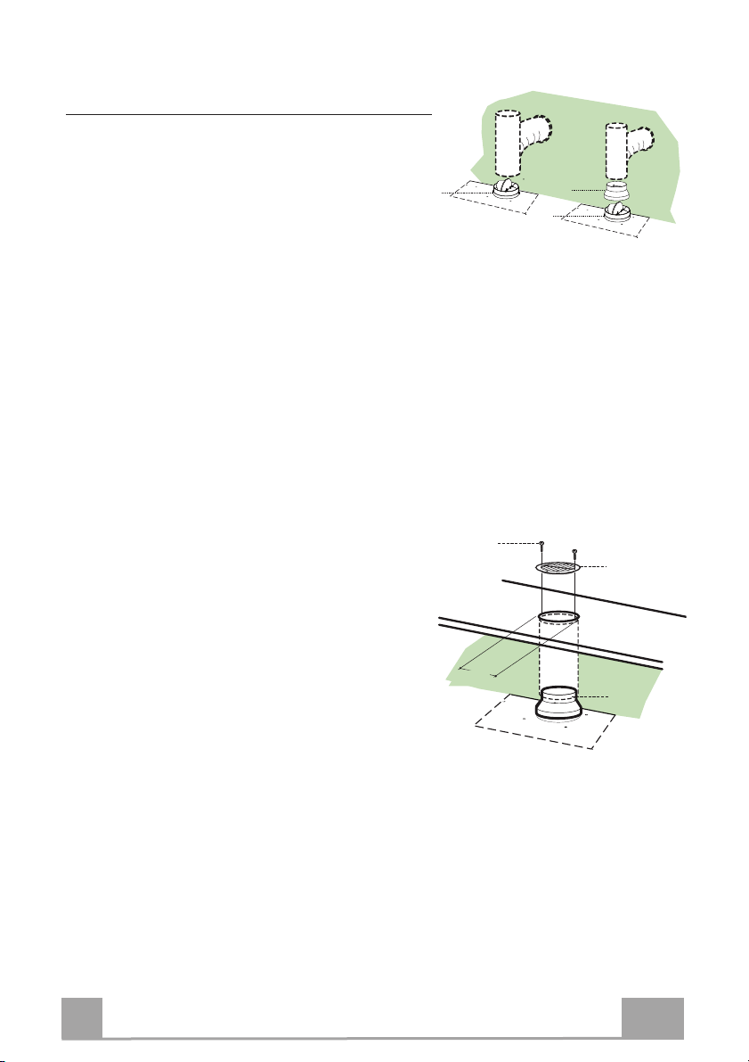
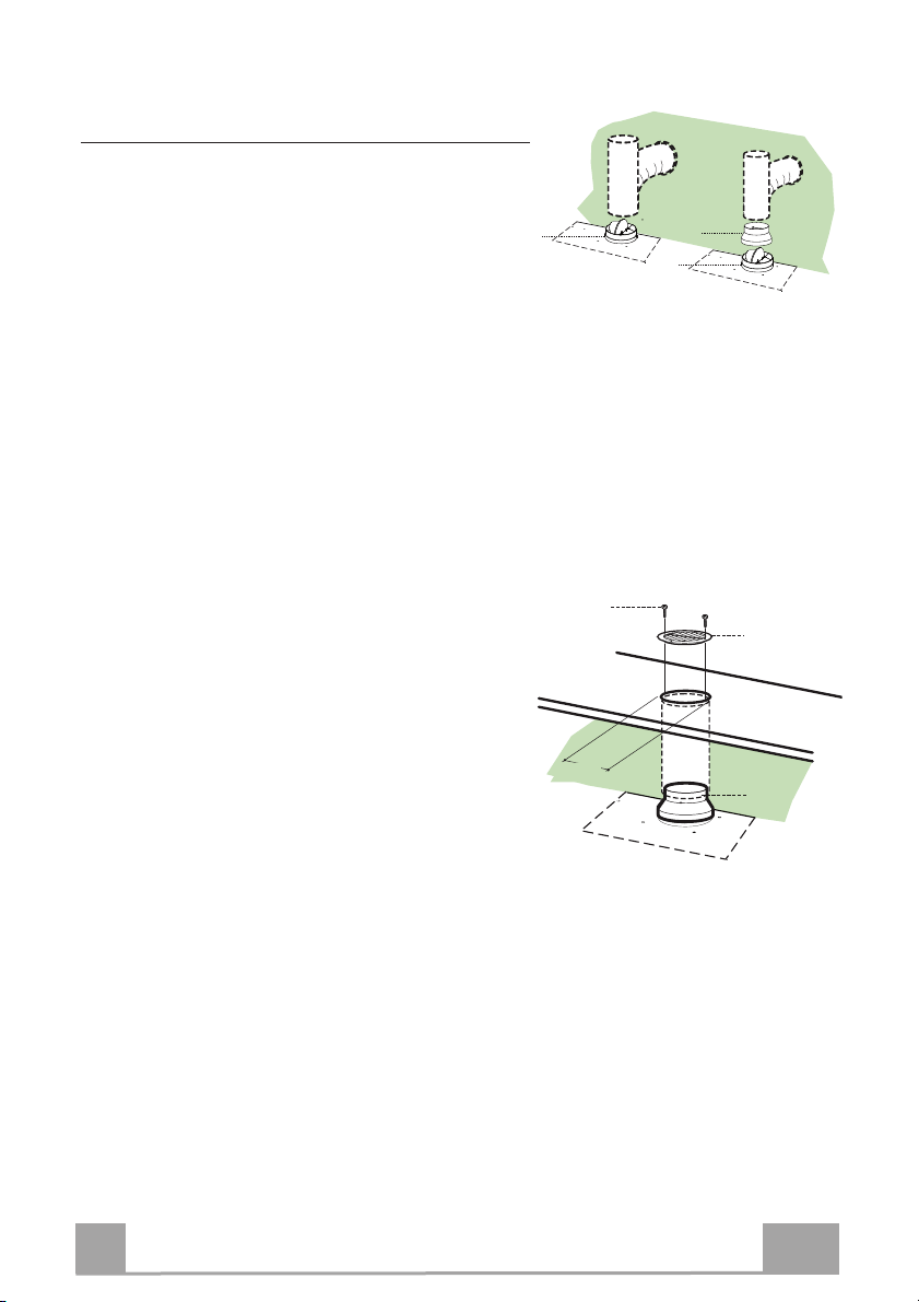
Anschluss im Umluftbetrieb
• In das eventuell über der Haube vorhandene Bord ein
Loch ø 125 mm bohren.
• Den Reduzierflansch 9 am Haubenaustritt anbringen.
• Den Flansch beim Luftaustritt am Bord oberhalb der
Haube mittels Rohr oder Schlauch ø120 mm an-
schließen.
• Das Rohr mit geeigneten Rohrschellen fixieren. Das
hierzu erforderliche Material wird nicht mitgeliefert.
• Das Luftleitgitter 8 mit Hilfe von 2 der mitgelieferten
Schrauben 12e (2,9 x 9,5) beim Austritt der rückzu-
führenden Luft fixieren.
• Sicherstellen, dass der Aktivkohle-Geruchsfilter vor-
handen ist.
9
ø 125
8
12e
ELEKTROANSCHLUSS
• Bei Anschluss der Haube an das Stromnetz muss ein zweipoliger Schalter mit einem Öff-
nungsweg von mindestens 3 mm zwischengeschaltet werden.
DE
9
9
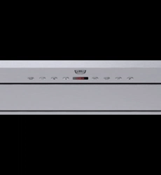
BEDIENUNG
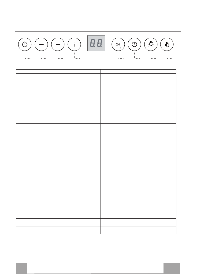
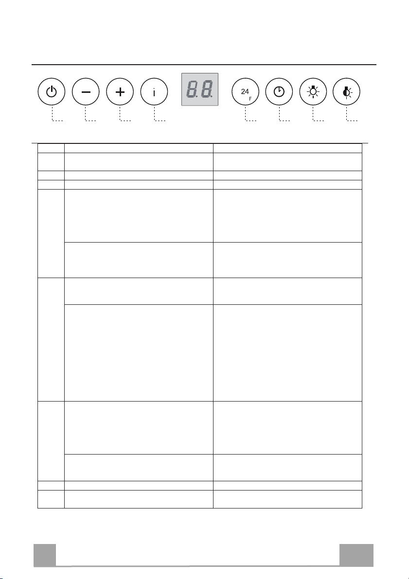
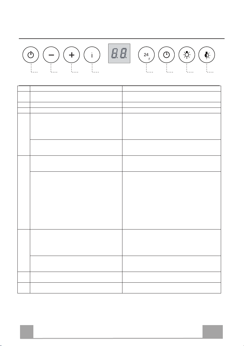
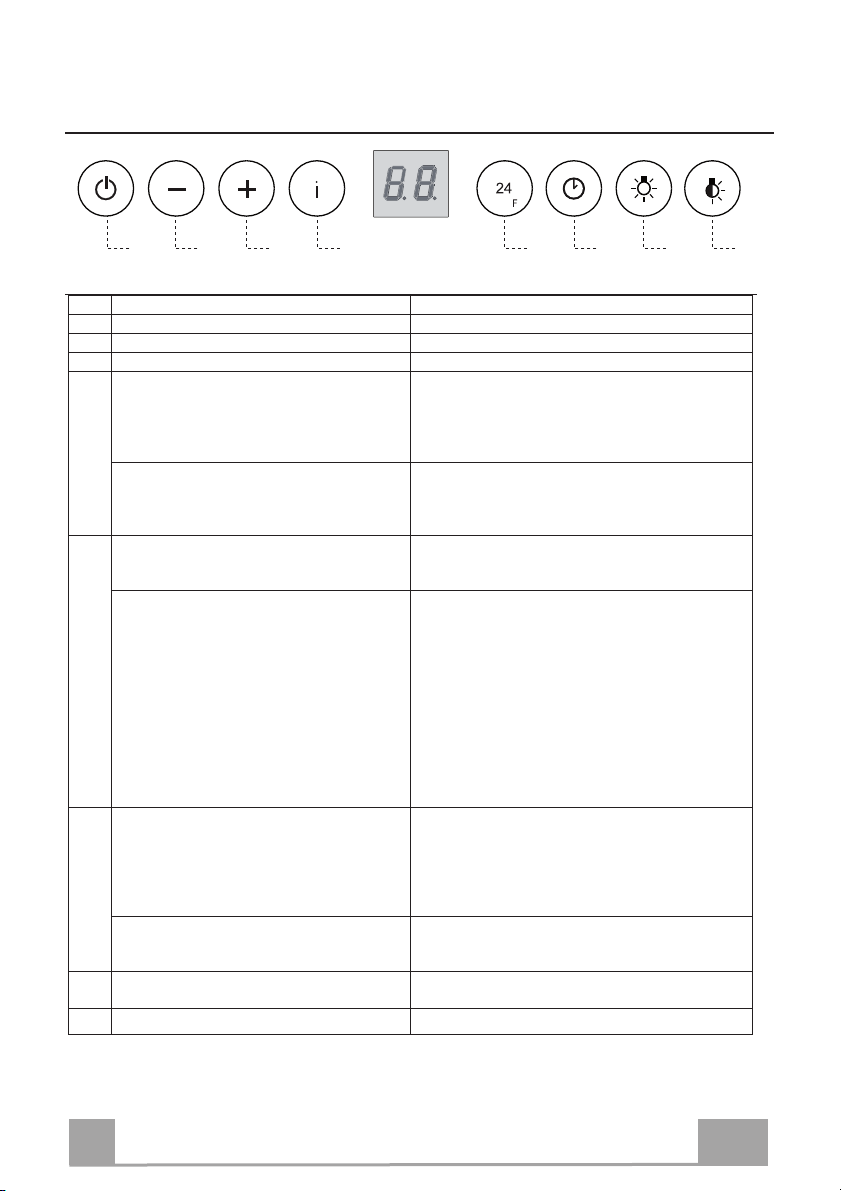
A B C D E F G H
Schalttafel
Taste Funktion Display
A Schaltet den Absaugmotor bei der ersten Geschwindig-
keitsstufe ein und aus.
Zeigt die eingestellte Geschwindigkeit an
B Vermindert die Betriebsgeschwindigkeit. Zeigt die eingestellte Geschwindigkeit an
C Erhöht die Betriebsgeschwindigkeit. Zeigt die eingestellte Geschwindigkeit an
D Aktiviert von jeder Geschwindigkeit aus, auch bei abge-
stelltem Motor, die Intensivgeschwindigkeit, die auf 6
Minuten zeitgeregelt ist. Nach Ablauf dieser Zeit kehrt
das System zu der zuvor eingestellten Geschwindigkeit
zurück. Für die Beseitigung von sehr intensiven Koch-
dünsten geeignet.
Macht einmal pro Sekunde abwechselnd HI und die Rest-
zeit sichtbar.
Mit zirka 5 Sekunden langem Gedrückthalten der Taste
bei abgeschalteten Verbrauchern (Motor+Licht) wird der
Alarm der Aktivkohlefilter aktiviert / deaktiviert.
FC+Pünktchen (2 Mal Blinken)–Alarm aktiviert.
FC+Pünktchen (1 Mal Blinken)–Alarm deaktiviert.
E 24H Funktion:
Aktiviert den Motor bei der ersten Geschwindigkeitsstufe
und ermöglicht eine Absaugung von 1 Minuten pro Stun-
de.
Zeigt 24 an und der Punkt unten rechts blinkt einmal pro
Sekunde, während der Motor in Betrieb ist
Wird durch Drücken der Taste deaktiviert.
Bei laufendem Filteralarm wird durch 3 Sekunden anhal-
tendes Drücken der Taste ein Reset des Alarms ausgelöst.
Derlei Anzeigen sind nur bei abgestelltem Motor sichtbar.
FF blinkt drei Mal.
Nach abgeschlossener Prozedur verlöscht die bisherige
Anzeige:
FG zeigt an, dass der Metallfettfilter gewaschen werden
muss. Dieser Alarm wird nach 100 effektiven Betriebs-
stunden der Abzugshaube ausgelöst.
FC zeigt an, dass die Aktivkohlefilter ausgewechselt
und die Metallfettfilter gewaschen werden müssen. Dieser
Alarm wird nach 200 effektiven Betriebsstunden der Ab-
zugshaube ausgelöst.
F Funktion Delay
Aktiviert das automatische Ausschalten mit einer Verzö-
gerung von 30’. Vervollständigt die Beseitigung von
Restgerüchen. Kann von jeder Position aus eingeschaltet
werden und wird durch Drücken der Taste oder Abstellen
des Motors ausgeschaltet.
Zeigt die Betriebsgeschwindigkeit an und der Punkt unten
rechts blinkt einmal pro Sekunde.
Mit zirka 5 Sekunden langem Gedrückthalten der Taste
bei abgeschalteten Verbrauchern (Motor+Licht) wird die
Fernbedienung aktiviert / deaktiviert.
IR+Pünktchen (2 Mal Blinken)–Alarm aktiviert.
IR+Pünktchen (1 Mal Blinken)–Alarm deaktiviert.
G Schaltet die Beleuchtungsanlage auf höchster Intensitäts-
stufe ein und aus.
H Schaltet die Beleuchtung im Modus der Notbeleuchtung
ein oder aus.
DE
1
10
REINIGUNG UND WARTUNG
FERNBEDIENUNG (OPTION)
Dieses Gerät kann per Fernbedienung, die mit einer 3V-Batterie vom
Typ CR2032 (nicht mitgeliefert) versorgt wird, bedient werden.
• Die Fernbedienung nicht in der Nähe von Wärmequellen ablegen.
• Altbatterien zum Schutz der Umwelt in Sammelboxen entsorgen.
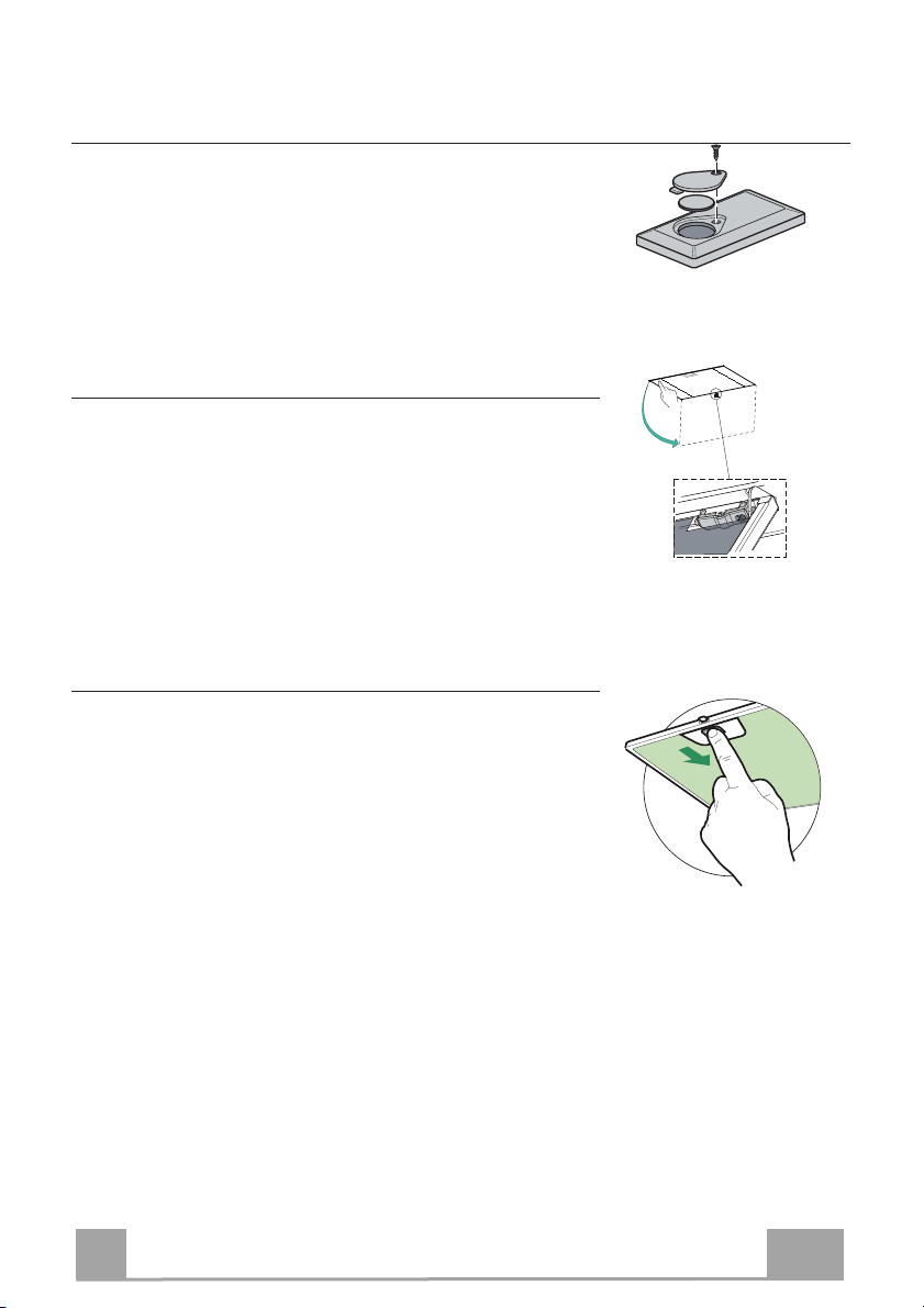
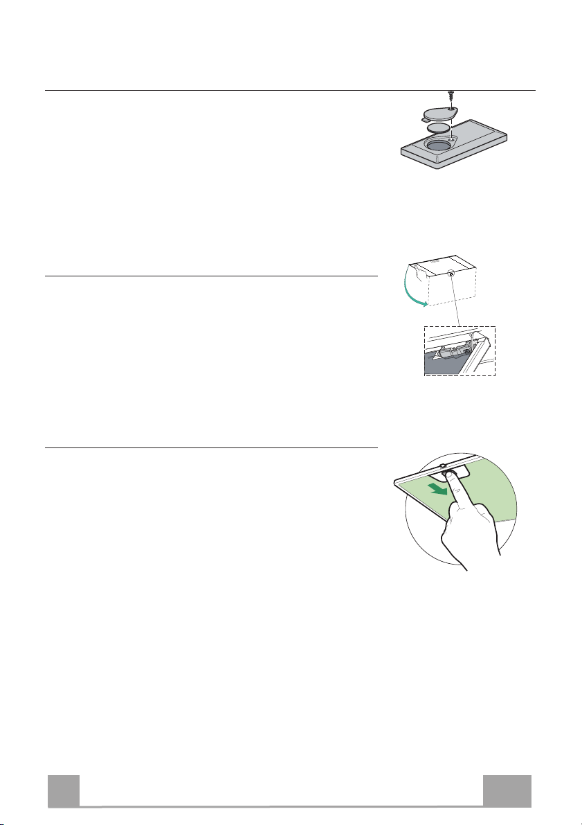
Öffnen des Paneels
• Das Paneel herausziehen.
• Die Außenflächen mit einem feuchten Lappen und einem
neutralen Flüssigreiniger säubern.
• Auch Innen mit einem feuchten Lappen und einem neutralen
Reinigungsmittel säubern; keine nassen Tücher oder
Schwämme, oder gar Wasser verwenden, und keine
schleifenden Mittel einsetzen.
Metallfettfilter
Die Fettfilter sind spülmaschinengeeignet und müssen gewaschen
werden, sobald am Display die Aufschrift FG erscheint oder
mindestens alle 2 Monate, oder auch öfter, je nach Intensität des
Gebrauchs.
Reset des Alarmsignals
• Die Beleuchtung und den Absaugmotor abschalten und dann
die 24-Stunden-Funktion deaktivieren, falls diese zuvor aktiv
war.
•Die Taste E drücken (siehe Absatz BEDIENUNG).
Reinigung der Filter
• Die Paneele zur langen Seite hin aufklappen
• Die Filter einzeln herausnehmen, indem sie in den hinteren
Teil der Gruppe geschoben und gleichzeitig nach unten
gezogen werden.
• Die Filter waschen, ohne sie zu verbiegen, und vor dem
erneuten Einbau trocknen lassen. (Die Farbe der
Filteroberfläche kann sich mit der Zeit verändern, was aber die
Wirksamkeit keinesfalls beeinträchtigt.)
• Nun den Filter wieder einbauen, so dass der Griff zur
Aussenseite zeigt.
• Die Paneele wieder schließen.
DE
1
11
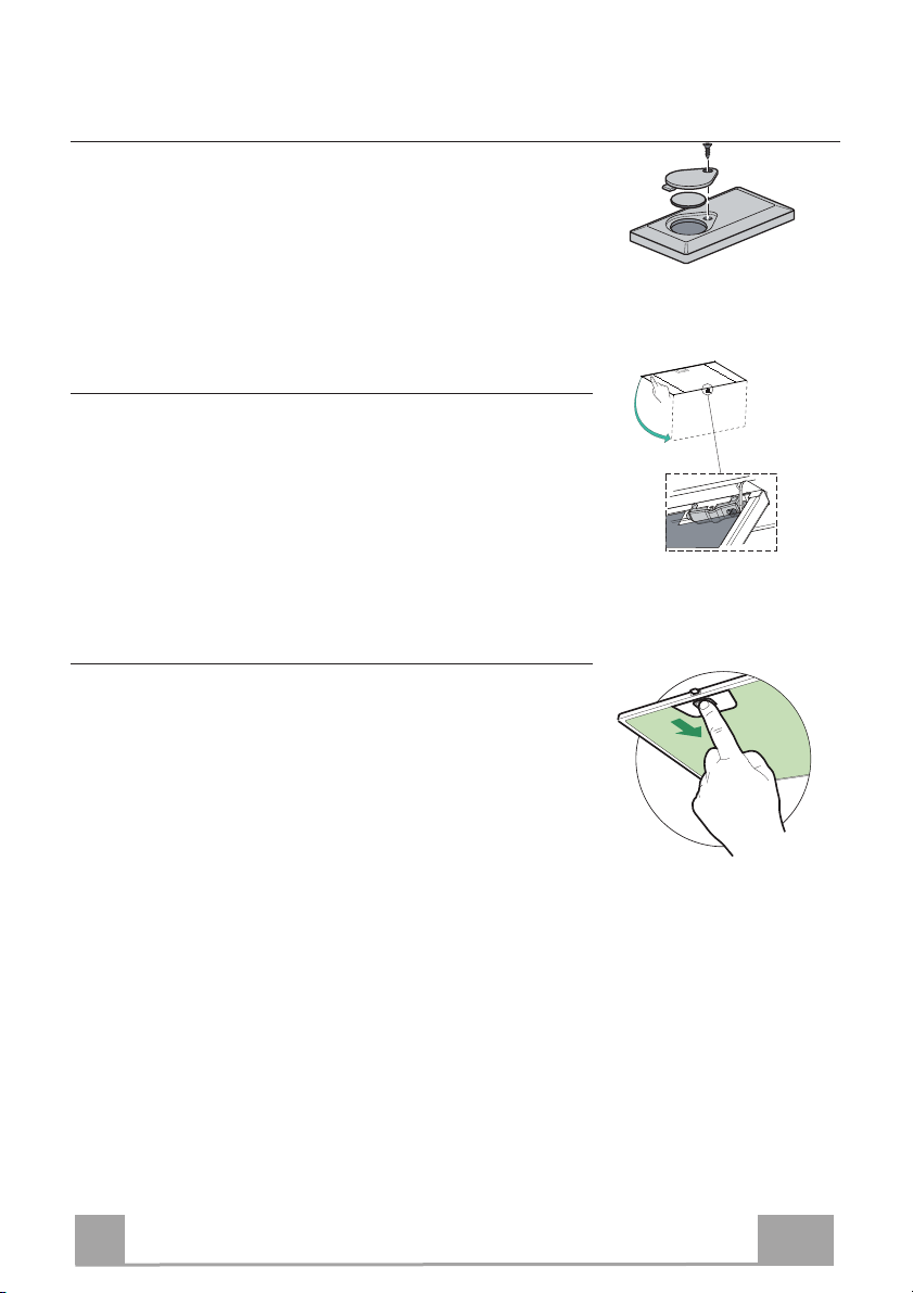
Aktivkohle-Geruchsfilter (Filterversion)
Die Aktivkohle-Geruchsfilter sind spülmaschinengeeignet und müssen gewaschen werden,
sobald am Display die Led S1 blinkt, oder mindestens alle 4 Monate, oder auch öfter, je nach
Intensität des Gebrauchs. Nach max. 5 Wäschen müssen die Filter erneuert werden. Die A-
larmmeldung, wenn zuvor aktiviert, erfolgt nur, wenn der Absaugmotor zugeschaltet ist.
Aktivierung des Alarmsignals
• Bei den Filterversionen der Abzugshauben wird die Alarmanzeige für Filtersättigung im
Augenblick der Installation oder in der Folge aktiviert.
• Die Beleuchtung und den Absaugmotor abstellen.
•Die Taste D zirka 5 Sekunden lang drücken.
• 2 Mal Blinken der Aufschrift FC+Pünktchen -- Alarm für Aktivkohlefiltersättigung
AKTIVIERT
• 1 Mal Blinken der Aufschrift FC+Pünktchen -- Alarm für Aktivkohlefiltersättigung
DEAKTIVIERT
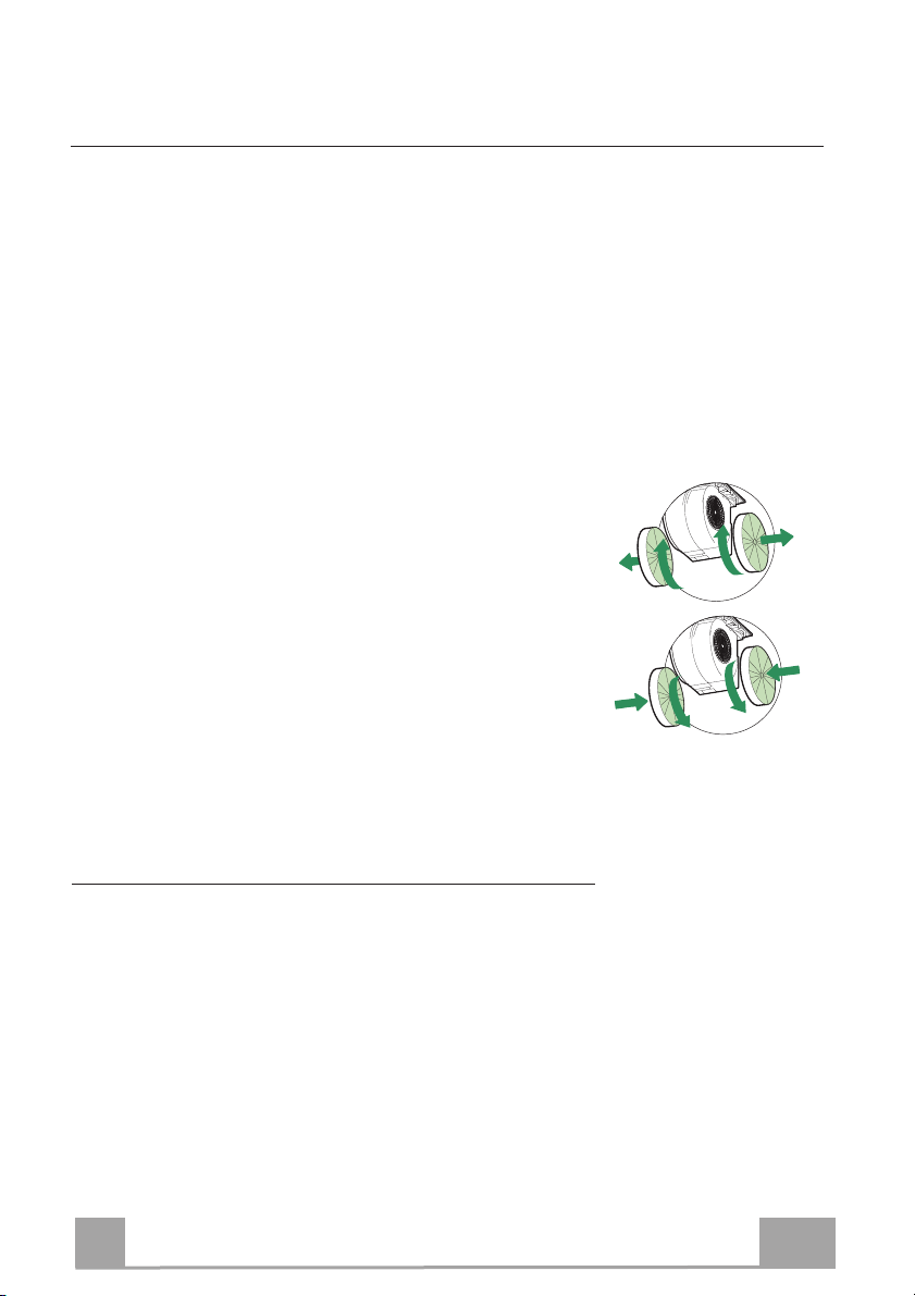
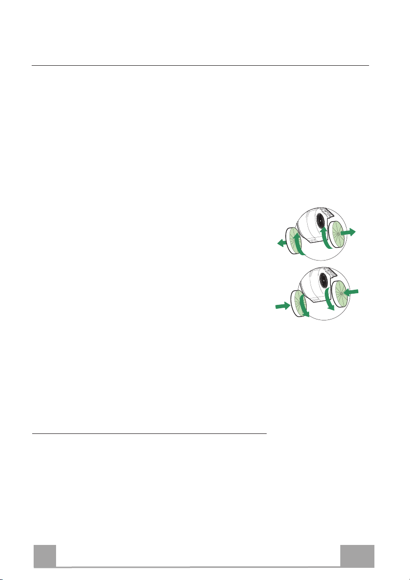
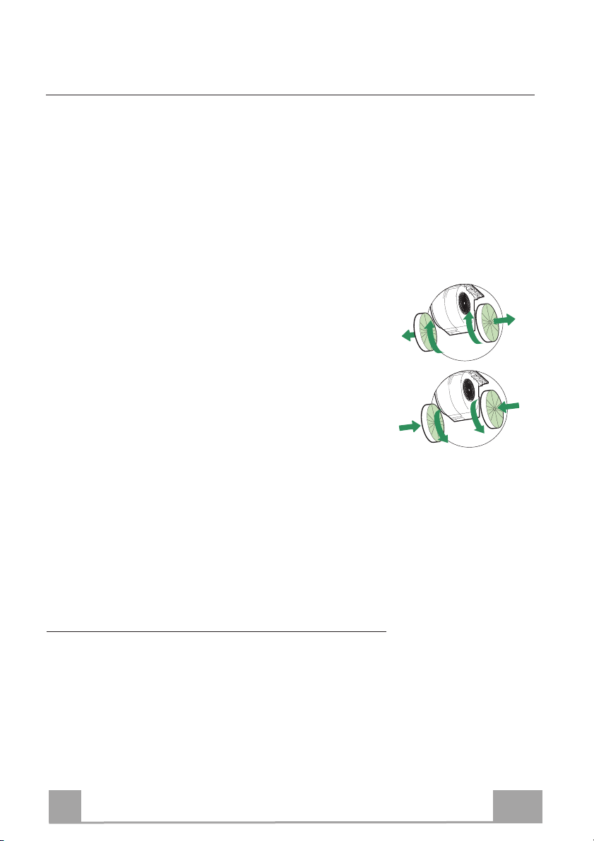
AUSWECHSELN DES AKTIVKOHLE-GERUCHSFILTERS
Reset des Alarmsignals
•
Die Beleuchtung und den Absaugmotor abschalten und dann die 24-
Stunden-Funktion deaktivieren, falls diese zuvor aktiv war.
• Die Taste E drücken (siehe Absatz GEBRAUCH).
Auswechseln des Filters
• Das Komfort-Paneel öffnen, indem es zur entsprechenden Kerbe gezo-
gen wird
• Die Fettfilter aus Metall entfernen.
• Die
verbrauchten Aktivkohle-Geruchsfilter wie angegeben ausbauen
(A).
• Die neuen Filter wie angegeben einbauen (B).
•
Die Fettfilter
aus Metall wieder einbauen.
•
Die Komfort-Paneele wieder verschließen.
A
B
Beleuchtung
LED-Strahler
• Für den Austausch der LED-Strahler wenden Sie sich bitte an den
Kundendienst.

FR
1
12
CONSIGNES DE SÉCURITÉ
Pour votre sécurité et pour garantir le fonctionnement correct de
l’appareil, veuillez lire attentivement ce manuel avant d’installer et de
mettre en fonction l’appareil. Toujours conserver ces instructions avec
l’appareil, même en cas de cession ou de transfert à une autre personne.
Il est important que les utilisateurs connaissent toutes les caractéristiques
de fonctionnement et de sécurité de l’appareil.
La connexion des câbles doit être effectuée par un technicien compétent.
x En aucun cas le fabricant ne peut être tenu pour responsable d’éventuels
dommages dus à une installation ou à une utilisation impropre.
x La distance de sécurité minimum entre le plan de cuisson et la hotte
aspirante est de 650 mm (certains modèles peuvent être installés à une
hauteur inférieure ; voir le paragraphe concernant les dimensions de travail
et l’installation).
x Si les instructions d’installation du plan de cuisson à gaz spécifient une
distance supérieure à celle indiquée ci-dessus, veuillez impérativement en
tenir compte.
x Assurez-vous que la tension du secteur correspond à celle indiquée sur la
plaque des caractéristiques apposée à l’intérieur de la hotte.
x Les dispositifs de sectionnement doivent être montés dans l’installation fixe
conformément aux normes sur les systèmes de câblage.
x Pour les appareils de Classe I, s’assurer que l’installation électrique de
votre intérieur dispose d’une mise à la terre adéquate.
x Reliez l’aspirateur du conduit de cheminée avec un tube ayant un diamètre
minimum de 120 mm. Le parcours des fumées doit être le plus court
possible.
x Respecter toutes les normes concernant l’évacuation de l’air.
x Ne reliez pas la hotte aspirante aux conduits de cheminée qui acheminent
les fumées de combustion (par ex. de chaudières, de cheminées, etc.).

FR
1
13
x Si vous utilisez l’aspirateur en même temps que des appareils non électriques
(par ex. fonctionnant au gaz), veillez à ce que la pièce soit adéquatement
ventilée, afin d’empêcher le retour du flux des gaz d’évacuation. Si vous utilisez
la hotte de cuisine en même temps que des appareils non alimentés à
l’électricité, la pression négative dans la pièce ne doit pas dépasser 0,04 mbar,
afin d’éviter que les fumées soient réaspirées dans la pièce où se trouve la hotte.
x Ne pas évacuer l’air à travers une conduite utilisée pour l’évacuation des fumées
des appareils de combustion alimentés au gaz ou avec d’autres combustibles.
x Si le cordon d’alimentation est endommagé, faites-le remplacer par le fabricant
ou par un technicien d’un service après-vente agréé.
x Branchez la fiche à une prise conforme aux normes en vigueur et dans une
position accessible.
x En ce qui concerne les dimensions techniques et de sécurité à adopter pour
l’évacuation des fumées, veuillez vous conformer scrupuleusement aux
règlements établis par les autorités locales.
AVERTISSEMENT : Avant d’installer la hotte, retirer les films de protection.
x Utilisez exclusivement des vis et des petites fournitures du type adapté pour la
hotte.
AVERTISSEMENT toute installation de vis et de dispositifs de fixation non
conformes à ces instructions peut entraîner des risques de décharges
électriques.
x Ne pas observer directement avec des instruments optiques (jumelles, lentilles
grossissantes...).
x Ne flambez pas des mets sous la hotte : sous risque de développer un incendie.
x Cet appareil peut être utilisé par des enfants de plus de 8 ans et par des
personnes dont les capacités physiques, sensorielles ou mentales sont
diminuées ou ayant une expérience et des connaissances insuffisantes, pourvu
que ce soit sous la surveillance attentive d’une personne responsable et après
avoir reçu des instructions sur la manière d’utiliser cet appareil en toute sécurité
et sur les dangers que cela comporte. Assurez-vous que les enfants ne jouent
pas avec cet appareil. Le nettoyage et l’entretien de la part de l’utilisateur ne
doivent pas être effectués par des enfants, à moins qu’ils ne soient surveillés.
x Surveillez les enfants. S’assurer qu’ils ne jouent pas avec l’appareil.

FR
1
14
x Cet appareil n’est pas destiné à être utilisé par des personnes (enfants
compris) dont les capacités physiques, sensorielles ou mentales sont
diminuées ou ayant une expérience et des connaissances insuffisantes, à
moins que celles-ci ne soient attentivement surveillées et instruites.
Les parties accessibles peuvent devenir très chaudes durant l’utilisation
des appareils de cuisson.
x Nettoyer et/ou remplacer les filtres après le délai indiqué (danger
d’incendie). Voir le paragraphe Nettoyage et Entretien.
x Veillez à ce que la pièce bénéficie d’une ventilation adéquate lorsque la
hotte fonctionne en même temps que des appareils utilisant du gaz ou
d’autres combustibles (non applicable aux appareils qui évacuent l’air
uniquement dans la pièce).
x Le symbole
marqué sur le produit ou sur son emballage indique que ce
produit ne peut pas être éliminé comme déchet ménager normal. Lorsque
ce produit doit être éliminé, veuillez le remettre à un centre de collecte
prévu pour le recyclage du matériel électrique et électronique. En vous
assurant que cet appareil est éliminé correctement, vous participez à
prévenir des conséquences potentiellement négatives pour l'environnement
et pour la santé, qui risqueraient de se présenter en cas d’élimination
inappropriée. Pour toute information supplémentaire sur le recyclage de ce
produit, contactez votre municipalité, votre déchetterie locale ou le magasin
où vous avez acheté ce produit.
FR
1
15
CARACTERISTIQUES
Encombrement
Composants
Réf. Q.té Composants de Produit
1 1 Corps Hotte équipé de: Commandes, Lumière, Groupe
Ventilateur, Filtres
8 1 Grille en Direction Sortie Air
9 1 Flasque de Réduction ø 150-120 mm
10 1 Buse avec clapet ø 150 mm
Réf. Q.té Composants pour l ’installation
12a 10 Vis
12e 2 Vis 2,9 x 9,5
Q.té Documentation
1 Manuel d’instructions
10
9
8
12e
FR
1
16
INSTALLATION
Montage du corps de hotte
AVANT DE MONTER LA HOTTE DANS L’ARMOIRE MURALE SUIVRE LA MARCHE CI-DESSOUS :
• Ouvrir le panneau en le tirant.
• Décrocher le panneau du corps de la hotte, en faisant coulisser le
levier du goujon de fixation spécialement prévu.
• Retirer les filtres à graisse.
• Débrancher le câblage des commandes en intervenant sur
les connecteurs.
• Débrancher le câblage des lumières en
intervenant sur les connecteurs.
• Retirer le cadre en desserrant
les 6 vis.
• La hotte peut être installée directement sur le
plan inférieur des armoires murales (650 mm
min. par rapport au plan de cuisson).
• Faire une entaille sur le plan inférieur de
l’armoire murale, de la manière indiquée.
• Insérer la Hotte jusqu’à accrocher les Supports
latéraux par encliquetage.
• Fixer avec 10 vis 12a fournies.
• Bloquer définitivement en serrant les Vis Vf
depuis le bas de la Hotte.
• Revisser le cadre avec les 4 vis précédemment retirées, rebrancher le câblage des commandes et
lumières, remonter le filtre à graisse et fermer le panneau.
0
260
13
495 - 675 -835
FR
1
17
Branchements
SORTIE AIR VERSION ASPIRANTE
Pour l’installation en version aspirante, relier la hotte au
tube de sortie au moyen d’un tube rigide ou flexible de
ø 150 ou 120 mm dont le choix est laissé à
l’installateur.
Raccord tube ø 150
• Insérer la bride avec soupape 10 ø 150 sur la sortie
du corps de hotte.
• Fixer le tube avec des colliers serre-tube appropriés.
Le matériel nécessaire n’est pas fourni.
Raccord tube ø 120
• Pour la liaison avec le tube ø120 mm, insérer la buse
de réduction 9 sur la bride ø 150 10 précédemment
installée.
• Fixer le tube avec des colliers serre-tube appropriés.
Le matériel nécessaire n’est pas fourni.
• Dans les deux cas, retirer les filtres anti-odeur à
charbon actif éventuels.
ø 120
ø 150
10
10
9
SORTIE AIR VERSION FILTRANTE
• Percer un trou de ø 125 mm. sur l’éventuelle Tablette
qui se trouve au-dessus de la Hotte.
• Insérer le flasque de réduction 9 sur la sortie du corps
de la hotte.
• Connecter la Flasque au trou de sortie sur la Tablette
qui se trouve au-dessus de la Hotte, au moyen d’un
tuyau rigide ou flexible de ø120 mm.
• Fixer le tube par des colliers appropriés. Le matériau
nécessaire n’est pas fourni.
• Fixer la Grille orientée 8 sur la sortie de l’air recyclé
à l’aide de 2 Vis 12e (2,9 x 9,5) fournies avec
l’appareil.
• S’assurer de la présence des filtres anti-odeur au
charbon actif.
9
ø 125
8
12e
BRANCHEMENT ELECTRIQUE
• Brancher la hotte sur le secteur en interposant un interrupteur bipolaire avec ouverture des
contacts d’au moins 3 mm.
FR
1
18
UTILISATION
A B C D E F G H
Tableau de commande
Touche Fonction Affichage
A Branche et débranche le moteur d’aspiration à la
première vitesse
Affiche la vitesse réglée
B Diminue la vitesse d’exercice. Affiche la vitesse réglée
C Augmente la vitesse d’exercice. Affiche la vitesse réglée
D Active la vitesse Intensive à partir de n’importe
quelle vitesse, même lorsque le moteur est éteint.
Cette vitesse est réglée pour une durée de 6 minutes,
après quoi le système retourne à la vitesse précé-
demment réglée. Fonction indiquée pour faire face
aux pointes d’émission de fumées de cuisson.
Affiche alternativement HI et le temps restant une
fois par seconde
Garder la touche appuyée pendant 5 secondes, lors-
que toutes les charges sont éteintes (Moteur+ Éclai-
rage), l’alarme des filtres au charbon actif se bran-
che/se débranche.
FC+Point (2 clignotements) – Alarme activée
FC+Point (1 Clignotement) – Alarme désactivée
E Fonction 24H
Active le moteur à la première vitesse et permet une
aspiration de 10 minutes par heure.
Affiche 24 et le point en bas à droite clignote une fois
par seconde, alors que le moteur est en fonction.
Appuyer sur la touche pour débrancher.
L’alarme filtres étant activée, appuyer sur la touche
pendant environ 3 secondes pour restaurer l’alarme.
Ces signalisations sont visibles seulement lorsque le
moteur est arrêté.
FF clignote trois fois.
À la fin de la procédure, la signalisation précédem-
ment affichée s’éteint :
FG Signale la nécessité de laver les filtres à graisse
métalliques. L’alarme entre en fonction après 100
heures de travail effectif de la hotte.
FC Signale la nécessité de remplacer les filtres au
charbon actif. Laver également les filtres à graisse
métalliques. L’alarme entre en fonction après 200
heures de travail effectif de la hotte.
F Fonction Départ différé
Active le débranchement automatique différé de 30’.
Adapté pour compléter l’élimination d’odeurs rési-
duelles. Activable à partir de n’importe quelle posi-
tion. Pour la désactiver, appuyer sur la touche ou
couper le moteur.
Affiche la vitesse d’exercice et le point en bas à
droite clignote une fois par seconde.
Garder la touche appuyée pendant 5 secondes, lors-
que toutes les charges sont éteintes (Moteur+ Éclai-
rage), la télécommande se branche/se débranche.
IR+Point (2 clignotements) – Alarme activée
FC+Point (1Clignotement) – Alarme désactivée
G Allume et éteint l’éclairage à l’intensité maximale.
H Branche et débranche l’éclairage en mode lumière de
courtoisie.
FR
1
19
NETTOYAGE ET ENTRETIEN
TÉLÉCOMMANDE (FOURNIE SUR DEMANDE)
Cet appareil peut être commandé via une télécommande, alimentée
avec une batterie 3 V type CR2032 (non fournie).
• Ne pas ranger la commande à proximité de sources de chaleur.
• Ne pas jeter les batteries dans la nature, mais les déposer dans les
bornes de collecte.
Ouverture panneau
• Ouvrir le panneau en le tirant.
• Le nettoyer à l’extérieur avec un chiffon humide et un
détergent liquide neutre.
• Le nettoyer également à l’intérieur avec un chiffon humide et
un détergent neutre ; ne jamais utiliser des chiffons ou des
éponges mouillés, ni des jets d’eau ; ne pas utiliser de substan-
ces abrasives.
Filtres à graisse métalliques
Ils sont lavables même au lave-vaisselle et ils doivent être lavés
chaque fois que le symbole FG s’affiche ou au moins tous les 2
mois d’utilisation ou plus souvent en cas d’utilisation particuliè-
rement intensive.
Reset du signal d'alarme
• Éteindre les lumières et le moteur d’aspiration ; au cas où la
fonction 24h serait activée, il convient de la désactiver.
• Appuyer sur la touche E (Voir paragraphe utilisation).
Nettoyage filtres
• Ouvrir le Confort Panel en tirant sur l’encoche spéciale.
• Retirer les filtres un à la fois en les poussant vers l’arrière du
groupe, tout en tirant en même temps vers le bas.
• Laver les filtres en évitant de les plier et les laisser sécher avant
de les remonter (tout changement de couleur de la surface du
filtre, susceptible de se produire avec le temps, ne nuit en rien à
l’efficacité de ce dernier).
• Les remonter en veillant à ce que la poignée soit toujours vers
la partie visible externe.
• Refermer le Confort Panel.
FR
2
20
Filtres anti-odeur à charbon actif (version filtrante)
Également lavable au lave-vaisselle, le nettoyer lorsque la Led S1 clignote ou au moins tous
les 4 mois ou plus fréquemment en cas d’utilisation particulièrement intense, en garantissant le
fonctionnement jusqu’à un maximum de 5 lavages avant son remplacement. Le signal
d’alarme, si préalablement activé, a lieu seulement lorsque le moteur d’aspiration est en
marche.
Activation du signal d’alarme
• Dans les hottes en version filtrante, activer le signal d’alarme de saturation filtres au
moment de l’installation ou après.
• Éteindre les lumières et le moteur d’aspiration.
• Appuyer sur la touche D pour environ 5 sec.
• 2 clignotements inscription FC+Point -- Alarme saturation Filtre C.A. ACTIVÉE
• 1 clignotement inscription FC+Point -- Alarme saturation Filtre C.A. DÉSACTIVÉE
REMPLACEMENT DU FILTRE ANTI-ODEUR AU CHARBON ACTIF
Reset du signal d'alarme
• Éteindre les lumières et le moteur d’aspiration ; au cas où la
fonction 24h serait active, il convient de la désactiver.
• Appuyer sur la touche E (Voir paragraphe utilisation).
Remplacement du filtre
• Ouvrir le Confort Panel en tirant sur l’encoche spéciale.
• Retirer les filtres à graisse métalliques.
• Enlever les filtres anti-odeur au charbon actif saturés, comme
indiqué (A).
• Monter les nouveaux filtres, comme indiqué (B).
• Remonter les filtres à graisse métalliques.
• Refermer le Confort Panel.
A
B
Éclairage
• Pour le remplacement, contacter le Service après-vente (« Pour
l’achat, s’adresser au service après-vente »).
IT
2
21
INFORMAZIONI SULLA SICUREZZA
Per la propria sicurezza e per il corretto funzionamento dell’apparecchio, si
prega di leggere attentamente questo manuale prima dell’installazione e
della messa in funzione. Tenere queste istruzioni sempre insieme
all’apparecchio, anche in caso di cessione o trasferimento a terzi. È
importante che gli utilizzatori conoscano tutte le caratteristiche di
funzionamento e sicurezza dell’apparecchio.
Il collegamento dei cavi deve essere effettuato da un tecnico competente.
• Il fabbricante non potrà ritenersi responsabile per eventuali danni risultanti da
un’installazione o utilizzazione impropria.
• La distanza minima di sicurezza tra il piano cottura e la cappa aspirante è di
650 mm (alcuni modelli possono essere installati a un’altezza inferiore;
vedere il paragrafo relativo alle dimensioni di lavoro e all’installazione).
• Se le istruzioni di installazione del piano cottura a gas specificano una
distanza maggiore di quella sopra indicata, è necessario tenerne conto.
• Controllare che la tensione di rete corrisponda a quella indicata sulla targa
dati applicata all’interno della cappa.
• I dispositivi di sezionamento devono essere installati nell’impianto fisso in
conformità alle normative sui sistemi di cablaggio.
• Per gli apparecchi di Classe I, controllare che la rete di alimentazione
domestica disponga di un adeguato collegamento a massa.
• Collegare la cappa alla canna fumaria con un tubo di diametro minimo di 120
mm. Il percorso dei fumi deve essere il più corto possibile.
• Devono essere rispettate tutte le normative riguardanti lo scarico dell’aria.
• Non collegare la cappa aspirante ai condotti fumari che trasportano fumi di
combustione (per es. di caldaie, camini ecc.).
IT
2
22
• Se la cappa è utilizzata in combinazione con apparecchi non elettrici (per es.
apparecchi a gas), deve essere garantito un sufficiente grado di aerazione nel
locale per impedire il ritorno di flusso dei gas di scarico. Quando la cappa per
cucina è utilizzata in combinazione con apparecchi non alimentati dalla
corrente elettrica, la pressione negativa nel locale non deve superare 0,04
mbar per evitare che i fumi vengano riaspirati nel locale dalla cappa.
• L’aria non deve essere evacuata attraverso un condotto utilizzato per lo
scarico dei fumi da apparecchi di combustione alimentati a gas o altri
combustibili.
• Il cavo di alimentazione, se danneggiato, deve essere sostituito dal
fabbricante o da un tecnico del servizio assistenza.
• Collegare la spina ad una presa di tipo conforme alle normative vigenti e in
posizione accessibile.
• Relativamente alle misure tecniche e di sicurezza da adottare per lo scarico
dei fumi è importante attenersi scrupolosamente ai regolamenti stabiliti dalle
autorità locali.
AVVERTENZA: prima di installare la cappa, rimuovere le pellicole di
protezione.
• Usare solo viti e minuteria di tipo idoneo per la cappa.
AVVERTENZA: la mancata installazione delle viti o dei dispositivi di
fissaggio in conformità alle presenti istruzioni può comportare rischi di
scosse elettriche.
• Non osservare direttamente con strumenti ottici (binocolo, lente
d’ingrandimento….).
• Non cuocere al flambé sotto la cappa: si potrebbe sviluppare un incendio.
• Questo apparecchio può essere utilizzato da bambini di età non inferiore a 8
anni e da persone con ridotte capacità psico-fisico-sensoriali o con
esperienza e conoscenze insufficienti, purché attentamente sorvegliati e
istruiti su come utilizzare in modo sicuro l’apparecchio e sui pericoli che ciò
comporta. Assicurarsi che i bambini non giochino con l’apparecchio. Pulizia e
manutenzione da parte dell’utente non devono essere effettuate da bambini,
a meno che non siano sorvegliati.
• Sorvegliare i bambini, assicurandosi che non giochino con l’apparecchio.
IT
2
23
• L’apparecchio non deve essere utilizzato da persone (bambini compresi) con
ridotte capacità psico-fisico-sensoriali o con esperienza e conoscenze
insufficienti, a meno che non siano attentamente sorvegliate e istruite.
Le parti accessibili possono diventare molto calde durante l’uso degli
apparecchi di cottura.
• Pulire e/o sostituire i filtri dopo il periodo di tempo specificato (pericolo di
incendio). Vedere il paragrafo Manutenzione e pulizia.
• Deve essere presente un’adeguata ventilazione nel locale quando la cappa
è utilizzata contemporaneamente ad apparecchi che utilizzano gas o altri
combustibili (non applicabile ad apparecchi che scaricano unicamente l’aria
nel locale).
• Il simbolo
sul prodotto o sulla sua confezione indica che il prodotto non
può essere smaltito come un normale rifiuto domestico. Il prodotto da
smaltire deve essere conferito presso un apposito centro di raccolta per il
riciclaggio dei componenti elettrici ed elettronici. Assicurandosi che questo
prodotto sia smaltito correttamente, si contribuirà a prevenire potenziali
conseguenze negative per l’ambiente e per la salute che potrebbero
altrimenti derivare dal suo smaltimento inadeguato. Per informazioni più
dettagliate sul riciclaggio di questo prodotto, contattare il Comune, il servizio
locale di smaltimento rifiuti oppure il negozio dove è stato acquistato il
prodotto.
IT
2
24
CARATTERISTICHE
Ingombro
Componenti
Rif. Q.tà Componenti di Prodotto
1 1 Corpo Cappa completo di: Comandi, Luce, Filtri, Grup-
po Aspiratore.
8 1 Griglia Direzionata
9 1 Flangia di riduzione ø 150-120 mm
10 1 Flangia con Valvola ø 150 mm
Rif. Q.tà Componenti di Installazione
12a 10 Viti
12e 2 Viti 2,9 x 9,5
Q.tà Documentazione
1 Libretto Istruzioni
10
9
8
12e
IT
2
25
INSTALLAZIONE
Montaggio Corpo Cappa
PRIMA DI MONTARE LA CAPPA AL PENSILE AGIRE COME SEGUE:
• Aprire il pannello aspirante tirandolo.
• Sganciare il pannello dal corpo cappa facendo scorrere
l’apposita leva del perno di fissaggio.
• Togliere i filtri Antigrasso.
• Scollegare il Cablaggio dei Comandi agendo sui connettori.
• Scollegare il Cablaggio Luci agendo sui connettori.
• Togliere la cornice svitan-
do le 6 Viti.
• La Cappa può essere installata direttamente
sul piano inferiore dei Pensili (650 mm min.
dal Piano di Cottura).
• Praticare un incasso sul piano inferiore del
Pensile, come indicato.
• Inserire la Cappa fino ad agganciare i Sup-
porti laterali a scatto.
• Fissare con 10 Viti 12a in dotazione.
• Bloccare definitivamente serrando le Viti Vf
dal sotto della Cappa.
• Riavvitare la Cornice con le 6 Viti tolte in precedenza, ricollegare il Cablaggio dei Comandi
e Luci, rimontare il filtro Antigrasso e il Pannello.
0
260
13
495 - 675 -835
IT
2
26
Connessioni
USCITA ARIA VERSIONE ASPIRANTE
Per installazione in Versione Aspirante collegare la
Cappa alla tubazione di uscita per mezzo di un tubo
rigido o flessibile di ø150 o 120 mm, la cui scelta è la-
sciata all'installatore.
Collegamento tubo ø 150
• Inserire la Flangia ø 150 10 sull’Uscita del Corpo
Cappa.
• Fissare il tubo con adeguate fascette stringitubo. Il
materiale occorrente non è in dotazione.
Collegamento tubo ø 120
• Per collegamento con tubo ø120 mm, inserire la
Flangia di riduzione 9 sulla flangia ø 150 10 prece-
dentemente installata.
• Fissare il tubo con adeguate fascette stringitubo. Il
materiale occorrente non è in dotazione.
• In ambedue i casi, togliere eventuali Filtri Antiodore
al Carbone attivo.
ø 120
ø 150
10
10
9
USCITA ARIA VERSIONE FILTRANTE
• Praticare un foro ø 125 mm sull’eventuale Mensola
soprastante la Cappa.
• Inserire la Flangia di riduzione 9 sull’uscita del Cor-
po Cappa.
• Collegare la Flangia al foro di uscita sulla Mensola
soprastante la Cappa con un tubo rigido o flessibile di
ø120 mm.
• Fissare il tubo con adeguate fascette stringitubo. Il
materiale occorrente non è in dotazione.
• Fissare la Griglia direzionata 8 sull’uscita con 2 Viti
12e (2,9 x 9,5) in dotazione.
• Assicurarsi della presenza dei Filtri antiodore al Car-
bone attivo.
9
ø 125
8
12e
CONNESSIONE ELETTRICA
• Collegare la Cappa all’Alimentazione di Rete interponendo un Interruttore bipolare con aper-
tura dei contatti di almeno 3 mm.
IT
2
27
USO
A B C D E F G H
Quadro comandi
Tasto Funzione Display
A Accende e spegne il motore di aspirazione alla prima
velocità.
Visualizza la velocità impostata
B Decrementa la velocità di esercizio. Visualizza la velocità impostata
C Incrementa la velocità di esercizio. Visualizza la velocità impostata
D Attiva la velocità Intensiva da qualsiasi velocità
anche da motore spento, tale velocità è temporizzata a
6 minuti, al termine del tempo il sistema ritorna alla
velocità precedentemente impostata. Adatta a fron-
teggiare le massime emissioni di fumi di cottura.
Visualizza alternamente HI e il tempo rimanente una
volta al secondo.
Tenendo il tasto premuto per circa 5 secondi, quando
tutti i carichi sono spenti (Motore+Luce), si Attiva /
Disattiva l’allarme dei Filtri al Carbone attivo.
FC+Punto (2Lampeggi)–Allarme Attivo.
FC+Punto (1Lampeggio)–Allarme Disattivo.
E Funzione 24H
Attiva il motore alla prima velocità e consente
un’aspirazione di 10 minuti ogni ora.
Visualizza 24 e il punto in basso a destra lampeggia una
volta al secondo, mentre il motore è in funzione.
Si disabilita premendo il tasto.
Con l’allarme filtri in corso premendo il tasto per
circa 3 secondi si effettua il reset dell’allarme.
Tali segnalazioni sono visibili solo a motore spento.
Lampeggia FF tre volte.
Terminata la procedura si spegne la segnalazione prece-
dentemente visualizzata:
FG segnala la necessità di lavare i filtri antigrasso me-
tallici. L’allarme entra in funzione dopo 100 ore di lavoro
effettivo della Cappa.
FC segnala la necessità di sostituire i filtri al carbone
attivo e devono anche essere lavati i filtri antigrasso me-
tallici. L’allarme entra in funzione dopo 200 ore di lavoro
effettivo della Cappa.
F Funzione Delay
Attiva lo spegnimento automatico ritardato di 30’.
Adatto per completare l’eliminazione di odori residui.
Attivabile da qualsiasi posizione, si disattiva premen-
do il tasto o spegnendo il motore.
Visualizza la velocità di esercizio e il punto in basso a
destra lampeggia una volta al secondo.
Tenendo il tasto premuto per circa 5 secondi, quando
tutti i carichi sono spenti (Motore+Luce), si Attiva /
Disattiva il Telecomando.
IR+Punto (2Lampeggi)–Allarme Attivo.
IR+Punto (1Lampeggio)–Allarme Disattivo.
G Accende e spegne l’impianto di illuminazione alla
massima intensità.
H Accende e spegne l’impianto di illuminazione in
modalità Luce di Cortesia.
IT
2
28
PULIZIA E MANUTENZIONE
TELECOMANDO (OPZIONALE)
Questo apparecchio può essere comandato per mezzo di un
telecomando, alimentato con una batteria da 3 V del tipo CR2032 (non
inclusa).
• Non riporre il telecomando in prossimità di fonti di calore.
• Non disperdere le pile nell’ambiente, depositarle negli appositi
contenitori.
Apertura Pannello
• Aprire il Pannello tirandolo.
• Pulirlo esternamente con un panno umido e detersivo liquido
neutro.
• Pulirlo anche internamente utilizzando un panno umido e de-
tergente neutro; non utilizzare panni o spugne bagnate, né getti
d’acqua; non utilizzare sostanze abrasive.
Filtri antigrasso metallici
Sono lavabili anche in lavastoviglie, e necessitano di essere lavati
quando sul display appare FG o almeno ogni 2 mesi circa di uti-
lizzo o più frequentemente, per un uso particolarmente intenso.
Reset del segnale di allarme
• Spegnere le Luci e il Motore di aspirazione, quindi qualora
fosse attivata la funzione 24h disattivarla.
• Premere il tasto E (Vedi paragrafo Uso).
Pulizia Filtri
• Aprire i Confort Panel tirandolo sull’apposita intacca.
• Togliere i Filtri uno alla volta, spingendoli verso la parte poste-
riore del gruppo e tirando contemporaneamente verso il basso.
• Lavare i Filtri evitando di piegarli, e lasciarli asciugare prima
di rimontarli. (Un’eventuale cambiamento del colore della su-
perficie del filtro, che potrebbe verificarsi nel tempo, non pre-
giudica assolutamente l’efficienza dello stesso.)
• Rimontarli facendo attenzione a mantenere la maniglia verso la
parte visibile esterna.
• Richiudere i Confort Panel.

IT
2
29
Filtri antiodore al Carbone attivo (Versione Filtrante)
Lavabile anche in lavastoviglie va pulito quando lampeggia il Led S1 o almeno ogni 4 mesi o
più frequentemente, per un uso particolarmente intenso, garantendo il funzionamento fino ad
un massimo di 5 lavaggi prima della sostituzione. La segnalazione di Allarme, se preventiva-
mente attivata, si verifica solo quando è azionato il Motore di aspirazione.
Attivazione del segnale di allarme
• Nelle Cappe in Versione Filtrante, la segnalazione di Allarme saturazione Filtri va attivata al
momento dell’installazione o successivamente.
• Spegnere le Luci e il Motore di aspirazione.
• Premere il tasto D per circa 5 Secondi:
• 2 Lampeggi scritta FC+Puntino -- Allarme saturazione Filtro C.A. ATTIVATO.
• 1 Lampeggio scritta FC+Puntino -- Allarme saturazione Filtro C.A. DISATTIVATO.
SOSTITUZIONE FILTRO ANTIODORE AL CARBONE ATTIVO
Reset del segnale di allarme
• Spegnere le Luci e il Motore di aspirazione, quindi qualora
fosse attivata la funzione 24h disattivarla.
• Premere il tasto E (Vedi paragrafo Uso).
Sostituzione Filtro
• Aprire i Confort Panel tirandolo sull’apposita intacca.
• Togliere i Filtri antigrasso metallici.
• Rimuovere i FiltrI antiodore al Carbone attivo saturo, come
indicato (A).
• Montare i nuovi Filtri,come indicato (B).
• Rimontare i Filtri antigrasso metallici.
• Richiudere i Confort Panel.
A
B
Illuminazione
• Per la sostituzione contattare l’Assistenza Tecnica ("Per
l'acquisto rivolgersi all'assistenza tecnica").
EN
3
30
SAFETY INFORMATION
For your safety and correct operation of the appliance, read this manual
carefully before installation and use. Always keep these instructions
with the appliance even if you move or sell it. Users must fully know the
operation and safety features of the appliance.
The wire connection has to be done by specialized technician.
x The manufacturer will not be held liabl
e for any damages resulting from
incorrect or improper installation.
x The minimum safety distance between the cooker top and the extractor
hood is 650 mm (some models can be installed at a lower height,
please refer
to the paragraphs on work
ing dimensions and installation).
x If the instructions for
installation for the gas hob specify a greater
distance, this must be respected.
x Check that the mains voltage corresponds to that indicated on the
rating plate fixed to the inside of the hood.
x Means for disconnection must be incorporated in the fixed wiring in
accordance with the wiring rules.
x For Class I appliances, check that the domestic power supply
guarantees adequate earthing.
x Connect the extractor to the exhaust flue through a pipe of minimum
diameter 120 mm. The route of the flue must be as short as possible.
x Regulations concerning the discharge of air have to be fulfilled.
x Do not connect the extractor hood to exhaust ducts carrying
combustion fumes (boilers, fireplaces, etc.).
EN
3
31
x If the extractor is used in conjunction with non-electrical appliances
(e.g. gas burning appliances), a sufficient degree of aeration must be
guaranteed in the room in order to prevent the backflow of exhaust gas.
When the cooker hood is used in conjunction with appliances supplied
with energy other than electric, the negative pressure in the room must
not exceed 0,04 mbar to prevent fumes being drawn back into the room
by the cooker hood.
x The air must not be discharged into a flue that is used for exhausting
fumes from appliances bur
ning gas or
other fuels.
x If the supply cord is damaged, it must be replaced from the manufac-
turer or its service agent.
x Connect the plug to a socket complying with current regulations, lo-
cated in an accessible place.
x With regards to the technical and safety measures to be adopted for
fume dischar
ging it is important to closely follow the regulations pro-
vided by the local authorities.
WARNING: Before installing the Hood, remove the protective films.
x Use only scr
ews and small parts in sup
port of the hood.
WARNING: Failure to install the screws or fixing device in accordance
with these instructions may result in electrical hazards.
x Do not look directly at the light through optical devices (binoculars,
magnifying glasses…).
x Do not flambè under the r
ange hood; risk of fire.
x This appliance can be used by children aged from 8 years and above
and persons with reduced physical, sensory or mental capabilities or
lack of experience and knowledge if they have been given supervision
or instruction concerning use of the appliance in a safe way and under-
stand the hazards involved. Children shall not play with the appliance.
Cleaning and user maintenance shall not be made by children without
supervision.
x Children should be super
vised to ensure
that they do not play with the
appliance.
EN
3
32
x The appliance is not to be used by persons (including children) with re-
duced physical, sensory or mental capabilities, or lack of experience
and knowledge, unless they have been given supervision or instruction.
Accessible parts may become hot when used with cooking appliances.
x Clean and/or replace the Filters after the specified time period (Fire
hazard). See paragraph Care and Cleaning.
x There shall be adequate ventilation of the room when the range hood is
used at the same time as appliances burning gas or
other fuels (
not
applicable to appliances that only discharge the air
back into the r
oom).
x The symbol
on the product or on its packaging indicates that this
product may not be treated as household waste. Instead it shall be
handed over to the applicable collection point for the recycling of elec-
trical and electronic equipment. By ensuring this product is disposed of
correctly, you will help prevent potential negative consequences for the
environment and human health, which could otherwise be caused by
inappropriate waste handling of this product. For more detailed informa-
tion about recycling of this product, please contact your local city office,
your household waste disposal service or the shop where you pur-
chased the product.
EN
3
33
CHARACTERISTICS
Dimensions
Components
Ref. Q.ty Product Components
1 1 Hood Body, complete with :Controls, Light, Blower,
Filters
8 1 Directioned grid
9 1 Reducer Flange ø 150-120 mm
10 1 Damper ø 150 mm
Ref. Q.ty Installation Components
12a 10 Screws
12e 2 Screws 2,9 x 9,5
Q.ty Documentation
1 Instruction Manual
10
9
8
12e
EN
3
34
INSTALLATION
Fitting the Hood canopy
BEFORE FITTING THE HOOD TO THE WALL UNIT, PROCEED AS FOLLOWS:
• Open the suction panel by turning the specific knob.
•
Disconnect the panel from the hood canopy by sliding the
fixing pin lever.
• Remove grease filters.
•
Disconnect the wires to the Commands at the connectors.
• Disconnect the wires to the Light at the connectors.
• Remove the frame by
unfastening
the 6 screws.
•
The Hood can be installed directly on the
underside of the wall unit (Minimum 650 mm
from the Cooker Hob).
• Create an opening in the bottom of the wall
unit, as shown.
• Insert the hood until the side supports snap into
place.
• Fasten using the 10 screws 12a provided.
• Lock in position by tightening the screws Vf
from underneath the hood.
• Screw the Frame back into place using the 6 screws removed as described above, re-connect
the wires to the Commands and Light, replace the metal grease filter and the Panel.
0
260
13
495 - 675 -835
EN
3
35
Connections
DUCTED VERSION AIR EXHAUST SYSTEM
When installing the ducted version, connect the hood to
the chimney using either a flexible or rigid pipe ø 150
or 120mm, the choice of which is left to the installer.
To install a ø 150 pipe
• To install the dumper 10
• Fix the pipe in position using sufficient pipe clamps
(not supplied).
To install a ø 120 pipe
• To install a ø 120 mm air exhaust connection, insert
the reducer flange 9 on the dumper 10.
• Fix the pipe in position using sufficient pipe clamps
(not supplied).
• Remove any activated charcoal filters.
ø 120
ø 150
10
10
9
RECIRCULATION VERSION AIR OUTLET
• Cut a hole ø 125 mm in any shelf that may be posi-
tioned over the hood.
• Insert the reducer flange 9 on the hood body outlet.
• Connect the flange to the outlet on the shelf over the
hood by using a flexible or rigid pipe ø120 mm.
• Fix the pipe in position using sufficient pipe clamps
(not supplied).
• Fix the air outlet grid 8 on the recirculation air outlet
by using the 2 screws 12e (2,9 x 9,5) provided.
• Ensure that the activated charcoal filters have been
inserted.
9
ø 125
8
12e
ELECTRICAL CONNECTION
• Connect the hood to the mains through a two-
p
ole switch having a contact gap of at least 3
mm..
EN
3
36
USE
A B C D E F G H
Control panel
Button Function Display
A Turns the suction motor on and off at speed one. Displays the set speed
B Decreases the working speed. Displays the set speed
C Increases the working speed. Displays the set speed
D Activate intensive speed from any other speed,
including motor off. This speed is set to operate
for 6 minutes, after which the system returns to the
speed that was set before. Suitable to deal with
maximum levels of cooking fumes.
Displays HI and the time remaining once very second.
Press and hold the button for approximately 5
seconds, with all the loads turned off (Motor and
Lights), to turn the Activated Charcoal Filter
alarm On and Off.
FC+Punto (2 flashes)–Alarm On.
FC+Punto (1 flash)–Alarm Off.
E 24H function
Turns the suction motor on at speed one and
effects one 10 minute extraction every hour.
Displays 24 and the spot at the bottom right flashes once
every second, while the motor is running.
It is disabled by pressing the button.
When the filters alarm is triggered, the alarm can
be reset by pressing and holding this button for
approximately 3 seconds.
These indications are only visible when the motor
is turned off.
FF flashes three times.
When the procedure terminates, the indication shown
previously turns off:
FG indicates the need to wash the metal grease filters.
The alarm is triggered after the Hood has been in
operation for 100 working hours.
FC indicates the need to change the activated charcoal
filters, and also to wash the metal grease filters. The alarm
is triggered after the Hood has been in operation for 200
working hours.
F Delay function
Activate automatic switch-off with a 30’ delay.
Suitable to complete elimination of residual
odours. Can be activated from any position, and is
disabled by pressing the button or turning the
motor off.
Displays the operating speed and the spot at the bottom
right flashes once a second.
Press and hold the button for approximately 5
seconds, with all the loads turned off (Motor and
Lights), to turn the Remote Control On and Off.
IR+Punto (2 flashes)–Alarm On.
IR+Punto (1 flash)–Alarm Off.
G Turns the lighting system on and off at maximum
intensity.
H Turns the Courtesy Lighting on and off.

EN
3
37
CARE AND CLEANING
REMOTE CONTROL (OPTIONAL)
This appliance can be commanded using a remote control, powered by
a CR2032 type 3 V battery (not supplied).
• Do not place the remote control near heat sources.
• Do not discard the batteries with normal waste, they must be put into
the specific containers.
Opening Panel
• Open the Panel by pulling it.
• Clean the outside with a damp cloth and neutral detergent.
• Clean the inside using a damp cloth and neutral detergent; do
not use wet cloths or sponges, or jets of water; do not use
abrasive substances.
Metal grease filters
They can be washed in the dishwasher, and need to be cleaned
whenever the FG sign appears on the display or at least once
every 2 months use, or more frequently if use is particularly
intensive.
Resetting the alarm signal
• Turn the Lights and the Suction motor off, then disable the 24h
function, if enabled.
• Press button E (see the paragraph on Use).
Cleaning the Filters
• Open the Comfort panels by pulling on the recess.
• Remove the Filters one at a time, pushing them towards the
back of the unit and at the same time pulling downward.
• Wash the Filters without bending them, and leave them to dry
completely before replacing. (If the surface of the filter
changes colour as time goes by, this will have absolutely no
effect on the efficiency of the filter itself.)
• Replace, taking care to ensure that the handle faces forwards.
• Close the Comfort panels.
EN
3
38
Activated Charcoal Filter (Recirculation Version)
Can be washed in the dishwasher. It must be washed when Led S1 flashes or at least once
every 4 months, or more frequently if use is particularly intense. Guaranteed to operate after
washing for up to a maximum of 5 times before requiring replacement. The Alarm signal, if it
has been activated, only appears when the Suction motor is turned on.
Activating the alarm signal
• In Recirculation Version Hoods, the Filter Saturation Alarm must be activated on
installation or at a later date.
• Turn the Lights and the Suction Motor off.
• Press D and hold for approximately 5 Seconds:
• The message FC+Puntino flashes twice, A.C. Filter saturation alarm ACTIVATED
• The message FC+Puntino flashes once, A.C. Filter saturation alarm DEACTIVATED
CHANGING THE ACTIVATED CHARCOAL FILTER
Resetting the alarm signal
• Turn the Lights and the Suction motor off, then disable the 24h
function, if enabled.
• Press button E (see the paragraph on Use).
Changing the Filter
• Open the Comfort panels by pulling on the recess.
• Remove the Metal grease filters.
• Remove the saturated Activated Charcoal Filters, as indicated
(A).
• Fit the new Filters, as indicated (B).
• Replace the Metal grease filters.
• Close the Comfort panels.
A
B
Lighting unit
• For replacement contact technical support ("To purchase
contact technical support").


J
610
23910-30
V-ZUG AG
Industriestrasse 66, CH-630 Zug
Tel. +41 (0)58 767 67 67, Fax +41 (0)58 767 61 61
[email protected], www.vzug.com
Service-Center: Tel. 0800 850 850
B
'B