Owner's Manual
Manual del Propietario
®
ROOM AIR CONDITIONER
ACONDICIONADOR DE AIRE DE VENTANA
Model, Modelo 580. 73189
Sears, Roebuck and Co., Hoffman Estates, IL 60179 U.S.A.
www.sears.com
TABLE OF CONTENTS ........................ 2
WARRANTY .............................................. 2
SAFETY ..................................................... 3
ImportantSafety Instructions...................... 3
ELECTRICAL REQUIREMENTS .......4
INSTALLING THE POWER CORD .--.4
INSTALLATION ........................................ 5
Installation Requirements ......................... 5
Installation................................................ 6
How to Install....................... _.................... 6
Removalfrom Window................................. 8
OPERATION ............................................. 9
How and Why ........................................... 9
Normal Sounds ........................................ 9
Capacity and Running Time ..................... 9
Features ................................................. 10
Using the Air Conditioner ....................... 10
Display ................................................... 11
Remote Control ...................................... 12
MAINTENANCE ..................................... 13
Air Filter Cleaning ................................... 13
Air Conditioner Cleaning ........................ 13
HowtoRemovetheFrontGrille.................. 13
Howto ReplacetheFrontGrille.................. 13
TROUBLESHOOTING ......................... 14
Before Calling for Service ...................... 14
ESPANOL ................................................ 15
MASTER PROTECTION
AGREEMENTS ......................................31
SERVICE NUMBERS ............BackCover
FULL ONE YEAR WARRANTY ON
ROOM AIR CONDITIONER
For one year from the date of purchase, when this
air conditioner isoperated and maintained for
normal room cooling according to instructions in this
owner's manual, Sears will repair this air
conditioner, free of charge, if defective in material or
workmanship.
FULL FIVE-YEAR WARRANTY ON
SEALED REFRIGERATION SYSTEM
For five years from the date of purchase, when this
air conditioner is operated and maintained for
normal room cooling according to instructions in this
owner's manual, Sears will repair the sealed
refrigeration system (consisting of refrigerant,
connecting tubing, and compressor), free of charge,
if defective in material or workmanship.
WARRANTY SERVICE IS AVAILABLE BY
CONTACTING SEARS SERVICE AT
1-800-4-MY-HOME ®.
Warranty coverage applies only to air conditioners
used for non-commercial, private household
purposes.
This warranty applies only while this product is in
use in the United States.
This warranty gives you specific legal rights, and
you may also have other right which vary from state
to state.
Sears, Roebuck and Co., D/817WA,
Hoffman Estates, IL 60179 U.S.A.
-2-
IMPORTANT SAFETY INSTRUCTIONS
The safetyinstructionsbelow willtellyouhow to useyourroom airconditionertoavoidharmtoyourselfor
damagetoyourROOM AIRCONDITIONER.
FOR YOUR SAFETY
Do notstore or use gasoline or other flammable
vapors and liquidsin the vicinity of this or any other
appliance. Read product labels for flammability and
other warnings.
PREVENT ACCIDENTS
To reduce the risk of fire, electrical shook, or injury
to persons when using your air conditioner, follow
basic precautions, including the following:
• Be sure the electrical service is adequate for the
model you have chosen.
• Ifthe air conditioner is to be installed in a window,
you wil! probably want to clean both sides of the
glass first. If the window is a triple-treck type with a
screen panel included, you may want to remove
the screen completely before installation.
• Be sure the air conditioner has been securely and
correctly installed according to the separate
installation instructions provided with this manual.
Save this manual and installation instructions for
possible future use in removing or reinstalling this
unit.
• Use gloves when handling the air conditioner.
Be careful to avoid cuts from sharp metal finson
front and rear coils.
ELECTRICAL INFORMATION
The complete electrical rating of your new room air
conditioner is stated on the serial plate. Refer to the
rating when checking the electrical requirements.
• Be sure the air conditioner is properly grounded.
To minimize shock and fire hazards, proper
grounding is important. The power cord is
equipped with a three-preng grounding plug for
protection against shock hazards.
• Your air conditioner must be plugged into in a
properly grounded wall receptacle. If the wall
receptacle you intend to use is not adequately
grounded or protected by a time delay fuse or
circuit breaker, have a qualified electrician install
the proper receptacle.
• Do not run air conditioner with a protective
covering. This could result in mechanical damage
within the air conditioner.
• Do not use an extension cord or an adapter
plug.
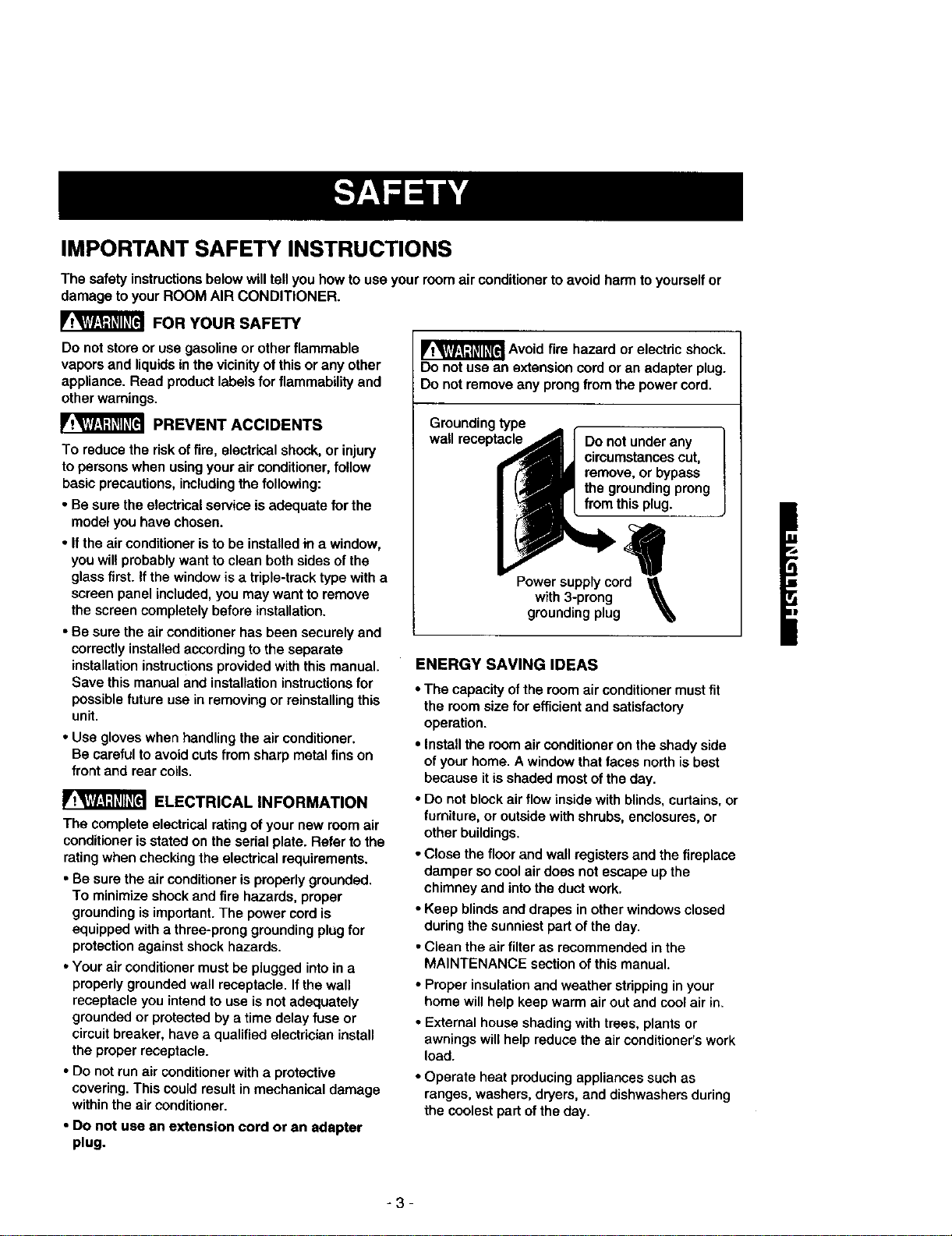
_ Avoidfire hazardor electric shock.
Do notuse an extension cordoran adapterplug.
Do notremoveany prongfrom the powercord.
Groundingtype
wall receptacle Do notunderany
circumstancescut,
remove,orbypass
the groundingprong
from thisplug.
Power supply cord
with 3-prong
grounding plug
ENERGY SAVING IDEAS
• The capacity of the room air conditioner must fit
the room size for efficient and satisfactory
operation.
• Install the room air conditioner on the shady side
of your home. A window that faces nodh is best
because it is shaded most ofthe day.
• Do not block air flow inside with blinds, curtains, or
furniture, or outside with shrubs, enclosures, or
other buildings.
• Close the floor and wall registers and the fireplace
damper so cool air does not escape up the
chimney and into the duct work.
• Keep blinds and drapes in other windows closed
during the sunniest part of the day.
• Clean the air filter as recommended in the
MAINTENANCE section of this manual.
• Proper insulation and weather stripping in your
home will help keep warm air out and cool air in.
• External house shading with trees, plants or
awnings will help reduce the air conditioner's work
load.
• Operate heat producing appliances such as
ranges, washers, dryers, and dishwashers during
the coolest part of the day.
-3-
OBSERVE ALL LOCAL CODES AND
ORDINANCES.
DO NOT, UNDER ANY CIRCUMSTANCES,
REMOVE THE POWER SUPPLY CORD
GROUND PRONG.
ELECTRICAL GROUND IS REQUIRED ON
THIS APPLIANCE.
For 230/208 volt 60 Hz, AC only, 15A fused
and properly grounded electrical supply is
required. A time delay fuse or time delay circuit
breaker is recommended. Use a dedicated
circuit, serving only this appliance.
DO NOT USE AN EXTENSION CORD.
RECOMMENDED GROUNDING METHOD
For your personal safety, this appliance must
be grounded. This appliance has a power
supply cord with a 3-prong grounding plug. To
minimize possible shock hazard, the cord must
be plugged into a mating grounding type wall
receptacle and grounded in accordance with
the National Electrical Code (ANSI/NFPA 70)
latest edition and all local codes and
ordinances. If a mating wall receptacle is not
available, it is the personal responsibility and
obligation of the customer to have a properly
grounded 3-prong wall receptacle installed by a
qualified electrician.
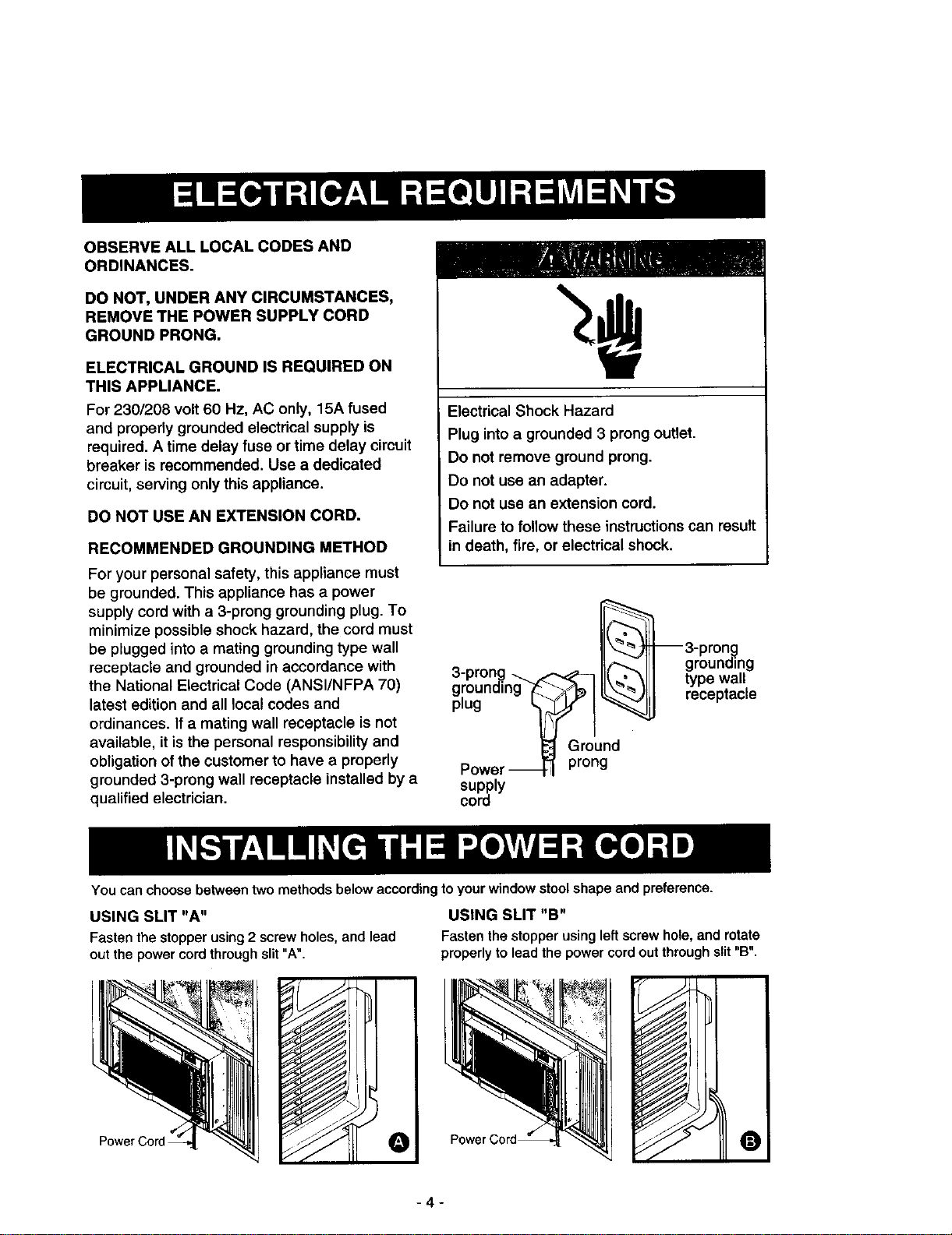
Electrical Shock Hazard
Plug into a grounded 3 prong outlet.
Do not remove ground prong.
Do not use an adapter.
Do not use an extension cord.
Failure to follow these instructions can result
in death, fire, or electrical shock.
_3-pron._
3 ron It_ I grounding
-P .g._ I1__" _, I type wall
g[ounelng i__> IL" JLLI receptacle
)yFI
L_ Ground
Power _ prong
supply
cord
You can choose between two methods below according to your window stool shape and preference.
USING SLIT "A"
Fasten the stopper using 2 screw holes, and lead
out the power cord through slit "A",
USING SLIT "B"
Fastenthestopper using leftscrewhole,androtate
properly to leadthepowercordoutthroughslit"B",
O
-4-
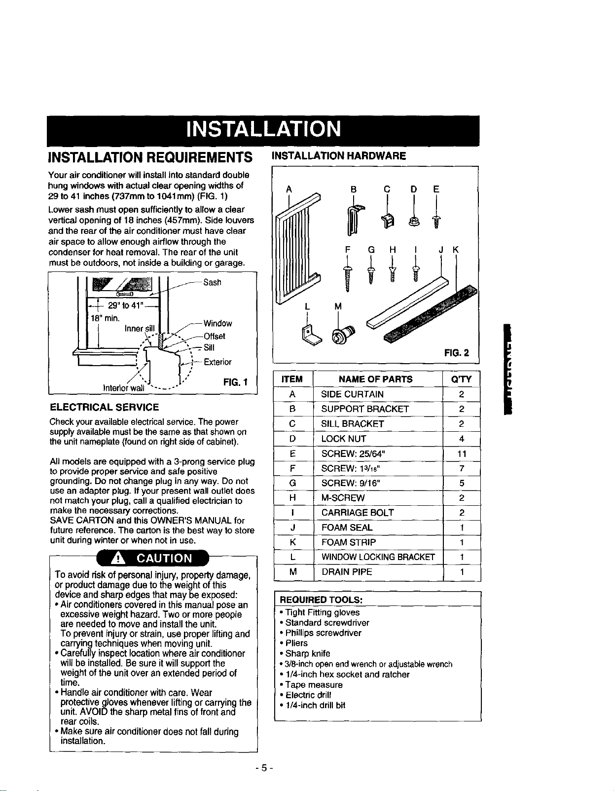
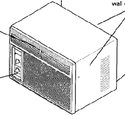
INSTALLATION REQUIREMENTS
Your air conditioner will install into standard double
hung windows with actual clear opening widths of
29 to 41 inches (737mm to 1041mm) (FIG. 1)
Lower sash must open sufficiently to allow a clear
vertical opening of 18 inches (457mm). Side louvers
and the rear of the air conditioner must have clear
air space to allow enough airflow through the
condenser for heat removal. The rear of the unit
must be outdoors, not inside a building or garage.
__,,_ Sash
4 2,"to,,"-!I
18"rain. I I • ,
t Innersill I I _Wnnaow
/ FOffset
_,,7 I.,,_,' Exterior
/ "-J L." FIG. 1
Interiorwail "-----"
ELECTRICAL SERVICE
Check your available electrical service. The power
supply available must be the same as that shown on
the unit nameplate (found on right side of cabinet).
All models are equipped with a 3-prong service plug
to provide proper service and safe positive
grounding. Do not change plug in any way. Do not
use an adapter plug. If your present wall outlet does
not match your plug, call a qualified electrician to
make the necessary corrections.
SAVE CARTON and this OWNER'S MANUAL for
future reference. The carton is the best way to store
unit during winter or when not in use.
To avoid riskofpersonal injury, property damage,
or product damage due to the weight of this
device and sharp edges that maybe exposed:
• Air conditioners coveredin this manual pose an
excessive weight hazard. Two or more people
are needed to move and install the unit.
To prevent injuryor strain, use proper liftingand
carrying techniques when moving unit.
• Carefully inspectlocation where air conditioner
will be installed. Be sure it will support the
weight of the unit over an extended period of
time.
• Handle air conditioner with care. Wear
protective gloveswhenever lifting or carrying the
unit. AVOID the sharp metal fins of front and
rear coils.
• Make sure air conditioner does not fall during
installation.
INSTALLATION HARDWARE
A B C D E
F G
L M
H I J K
FIG. 2
ITEM NAME OF PARTS Q'TY
A SIDE CURTAIN 2
B SUPPORT BRACKET 2
C SILL BRACKET 2
D LOCK NUT 4
E SCREW: 25/64" 11
F SCREW: 13116" 7
G SCREW: 9/16" 5
H M-SCREW 2
I CARRIAGE BOLT 2
J FOAM SEAL t
K FOAM STRIP 1
L WINDOW LOCKING BRACKET t
M DRAIN PIPE 1
REQUIRED TOOLS:
• Tight Fitting gloves
• Standard screwdriver
• Phillips screwdriver
• Pliers
• Sharp knife
• 3/8-inch open end wrenchor adjustable wrench
• 1/4-inch hex socket and ratcher
• Tape measure
• Electric drill
• 1/4-inch drillbit
-5-
INSTALLATION
Pick a location which will allow you to blow the cold
air into the area you want. Windows used for
installation must be strong enough to support the
weight of the air conditioner. Good installation with
special attention to the proper position of the unit
will lessen the chance that service will be needed.
When cooling more than one room. installation
location is very important. To cool your rooms, cold
air must be blown from the air conditioner in a
straight path.
HOW TO INSTALL
Ifthe air conditioner is blocked by a stormwindowframe,
see step 16 on page 8before beginning to install.
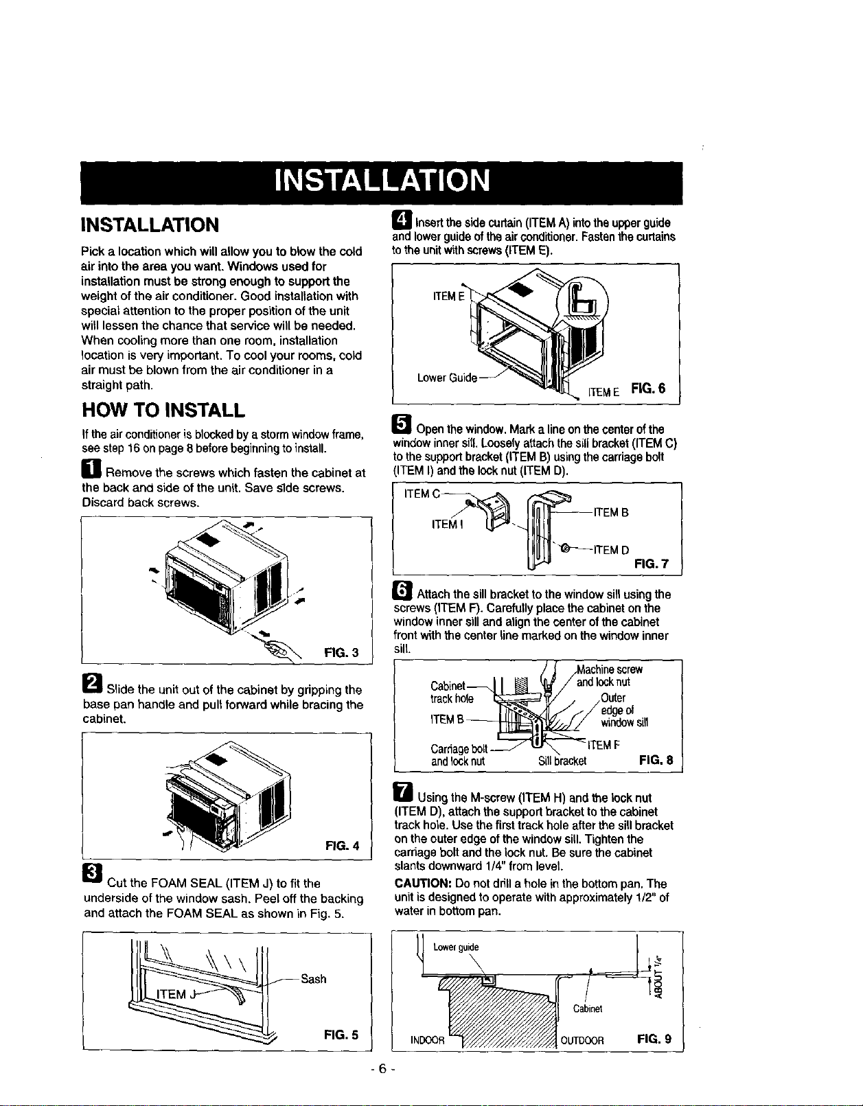
B Remove the screws which fasten the cabinet at
the back and side of the unit. Save slde screws.
Discard back screws.
"P.
_"_ Slide the unit out of the cabinet by gripping the
base pan handle and pull forward while bracing the
cabinet.
FIG. 4
_lcut the FOAM SEAL (ITEM J) to fit the
underside of the window sash. Peel off the backing
and attach the FOAM SEAL as shown in Fig. 5.
FIG. 5
D Insert the sidecurtain(ITEM A) intothe upperguide
and lowerguideofthe air conditioner.Fasten the curtains
to the unit with screws (ITEM E).
Lower€
iTEM E FIG.6
_"_ Open the window.Mark alineonthe center ofthe
windowinnersill. Loosely attach the siUbracket(ITEM C)
to the support bracket (ITEM B) using the carriage bolt
(ITEM I) and the lock nut (ITEM D).
ITEMI
r_ Attach the sill bracket to the window sill usingthe
screws (ITEM F). Carefully place the cabinet on the
window inner silland align the center of the cabinet
front with the center line marked on the window inner
sill.
Cabinet_ Lndlocknut
trackhole Outer
windowsill
Carriagebolt
and10cknut Sillbracket FIG. 8
_-_ Using the M-screw (ITEM H) and the lock nut
(ITEM D), attach the supportbracket to the cabinet
track hole. Use the first track hole after the sill bracket
on the outer edge of the window sill. Tighten the
carriage bolt and the lock nut. Be sure the cabinet
slants downward 1/4" from level.
CAUTION: Do not drill a hole in the bottom pan. The
unit is designed to operate with approximately 1/2" of
water in bottom pan.
Lowerguide
\
Cabinet
OUTDOOR
FIG. 9
-6-
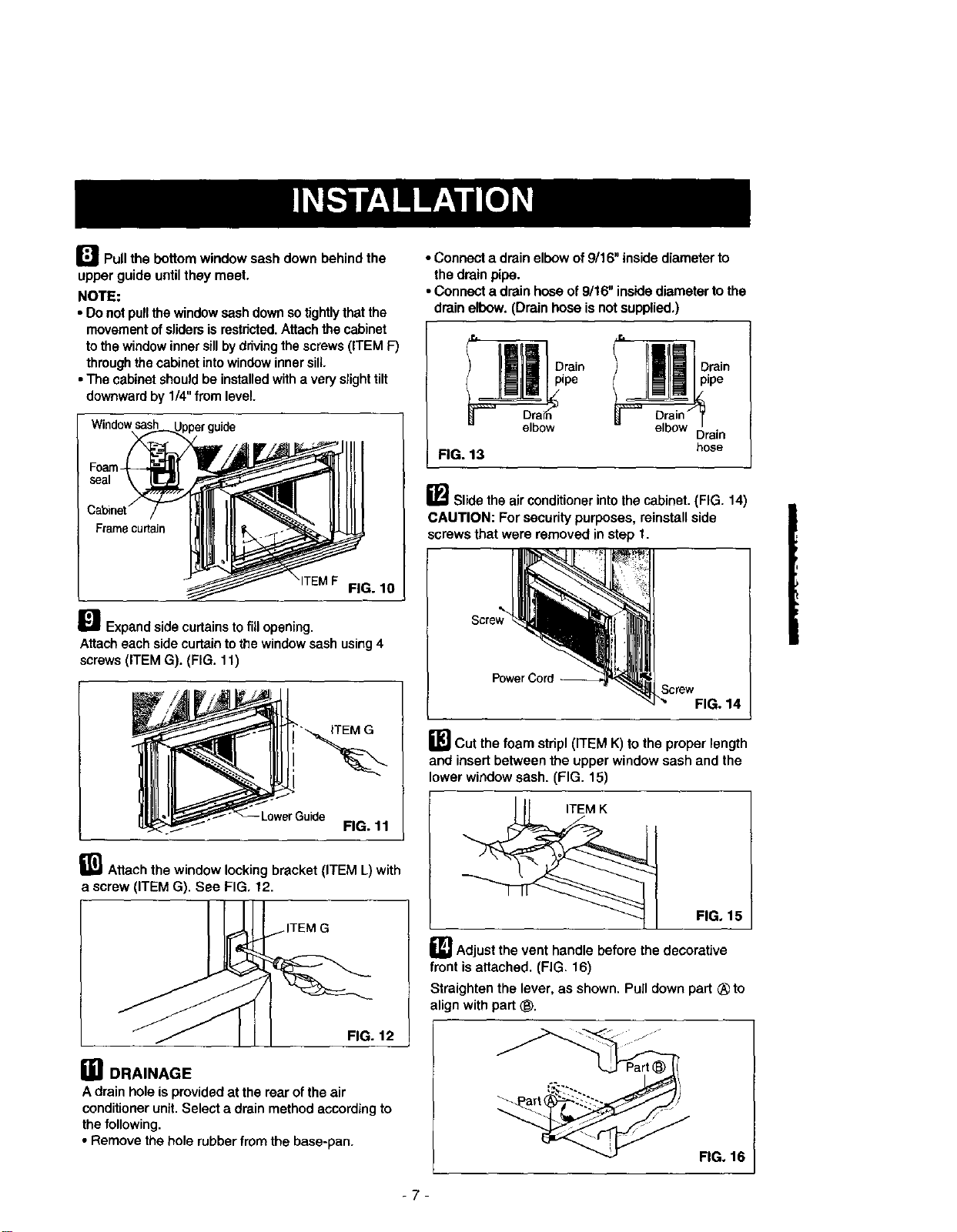
I_ Pull the bottom window sash down behind the
upper guide until they meet.
NOTE:
• Do notpullthe window sash downso tightlythat the
movement ofsliders isrestricted.Attach the cabinet
to the window inner sill bydrivingthe screws (ITEM F)
throughthe cabinet intowindow innersill.
• The cabinet should be installed witha very slight tilt
downwardby 1/4" from level.
Window sash
ITEM F FIG. 10
I_ Expand side curtains to fillopening.
Attach each side cudain to the windowsash using 4
screws (ITEM G). (FIG. 11)
iTEM G
FIG. 11
_11_Attach the window locking bracket (ITEM L) with
a screw (ITEM G). See FIG. 12.
ITEM G
FIG. 12
in DRAINAGE
A drain hole is provided at the rear ofthe air
conditioner unit. Select a drain method according to
the following.
• Remove the hole rubber from the base-pan.
• Connect a drain elbow of9/16" inside diameter to
the drainpipe.
• Connect a drain hose of 9/16" insidediameter to the
drain elbow. (Drain hose isnot supplied,)
pE)rain Drain
hose
FIG. 13
_ Slide the air conditionerintothe cabinet. (FIG. 14)
CAUTION: For security purposes, reinstall side
screws that were removed in step t.
Screw_
PowerCord_----
Screw
FIG. 14
B Cut the foam stdpl (ITEM K)to the proper length
and insert between the upper window sash and the
lower window sash. (FIG. 15)
FIG, 15
_ Adjust the vent handle before the decorative
front isattached. (FIG. 16)
Straighten the lever, as shown. Pull down part ® to
align with part (_.
FIG. 16
-7-
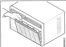
B FRONT INSTALLATION
Install the front grille(packed separately) onto the
cabinet as follows:
• Hook upper tabs of front grins into slots on the
cabinet top. (FIG. 17)
• Push front grille's tips towards the cabinet in order
to snap side tabs into the cabinet. (FIG, 17)
• Open the inlet grille, (FIG. 18)
• Install the screw (ITEM E) through the front grille.
(FIG. 18)
• Close inlet grille. (FIG. 19)
Front Installation
FIG. 17
ITEM E -
Front Installation
FIG. 18
Front Installation FIG. 19
I_IF AIR CONDITIONER IS BLOCKED BY
STORM WINDOW FRAME
• If storm window presentsinterference, fasten a 2"
wide wood striptothe innerwindow sillacrossthe full
width ofthe sill,The wood stripshould be thick
enough to raise the height ofthe window sillso that
the unitcan be installedwithoutinterference fromthe
the stormwindow frame. See FIG. 20,
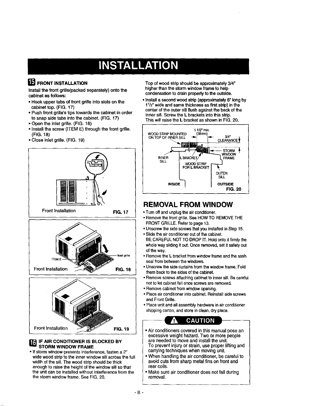
Top of wood stripshould be approximately3/4"
higherthan the storm windowframe to help
condensationto drainproperlyto the outside.
• Install a secondwood strip (approximately 6" longby
lf/2" wide and same thickness as firststrip) inthe
center of the outer sillflush against the backof the
inner silt.Screwthe L brackets intothis strip.
This willraise the L bracketas shown in FIG. 20.
1 1/2" rnin.
WOOD STRIP MOUNTED (38ram)
ON TOP OF INNER SILL _ 3/4"
E_ WINDOW
INNER FRAME
FIG. 20
REMOVAL FROM WINDOW
• Turn off and unplugthe airconditioner.
• Remove the frontgrille. See HOWTO REMOVETHE
FRONT GRILLE. Refer to page 13.
• Unscrew the side screws that you installed in Step 15.
• Slide the air conditioner out of the cabinet.
BE CAREFUL NOT TO DROP IT. Hold onto itfirmly the
whole way sliding it out. Once removed, set it safety out
of the way.
• Remove the L bracket from windowframe andthe sash
seal from between the windows.
• Unscrew the side curtains from the window frame. Fold
them back to the sides of the cabinet.
• Remove screws attaching cabinet to inner sill. Be careful
not to letcabinet fall once screws are removed.
• Remove cabinetfrom windowopening.
• Place air conditioner into cabinet. Reinstall side screws
and FrontGrille.
• Place unit and all assembly hardware in air conditioner
shipping carton, and store inclean, dry place.
•Air conditioners covered in this manualposean
excessiveweight hazard. Two or more people
are needed to move and install the unit.
To prevent injury or strain, use proper lifting and
carrying techniques when moving unit.
•When handlingthe airconditioner, becarefulto
avoid cuts from sharp metal fins on front and
rear coils.
• Make sure air conditioner does not fall during
removal.
-8-
HOW AND WHY
Your room air conditioner provides the following
functions to make hot weather living more
comfortable:
• Cools and circulates room air.
• Lowers humidity by removing excess moisture.
• Filters out summertime dust, dirt, and some
airborne impurities.
The air conditioner performs these functions by
drawing room air through a filter which traps dust
and dirt particles. The air then passes over a
cooling coilwhich refrigerates the air and removes
excess moisture. The same air is then returned to
the room- cooler, drier, and cleaner. Moisture
removed from the room air iscarried to the outside
and evaporated.
Your air conditioner is designed to be easy to
operate and to provide plenty of cooling power.
NORMAL SOUNDS FIG.21
Aside from the regular fan motor and compressor
sounds coming from your air conditioner, you will
once in a while hear a pinging sound. This is the
result of moisture being picked upfrom the air in the
room and thrown against the air conditioner's fan.
This is normal and should not be cause for concern.
Also, do not be alarmed ifyou hear a slight hissing
or gurgling sound coming from your air conditioner
after it is off. These are normal coolant noises.
CAPACITY AND RUNNING TIME
Proper unit size is important in deciding the desired
comfort for the area you want to cool. An
undersized unitwill not have the capability to cool,
leaving the area uncomfortably warm. The proper
size is determined by the number of square feet in
the area to be cooled, indoor and outdoor
temperature and humidity.
Whenever the heat or humidity load is above normal
the air conditioner must run longer and more often
to keep the desired temperature you have selected,
Under heavy heat load conditions the air conditioner
may need to run constantly to keep the temperature
you want.
At times using the MED FAN setting to circulate the
room air may make it comfortable even though the
air is not being cooled. This will decrease your cost
of use.
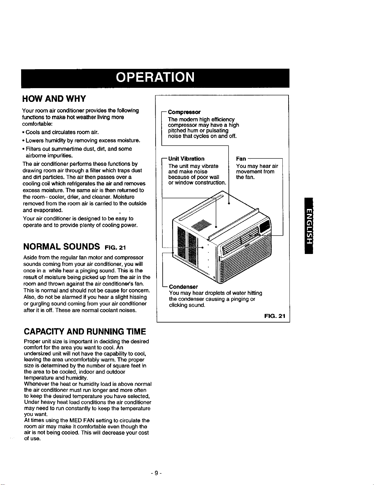
i ompressor
The modem high efficienc,!
compressor may have a high
pitched hum or pulsating
noise that cycles on andoff,
-- Unit Vibration
The unit may vibrate
and make noise
because of poor wall
or window construction.
Fan
You may hear air
movement from
the fan.
You may hear droplets of water hitting
the condenser causing a pinging or
clicking sound.
FIG. 21
-9-
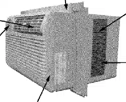
FEATURES
1 15 6 5
i
18 179 8 11
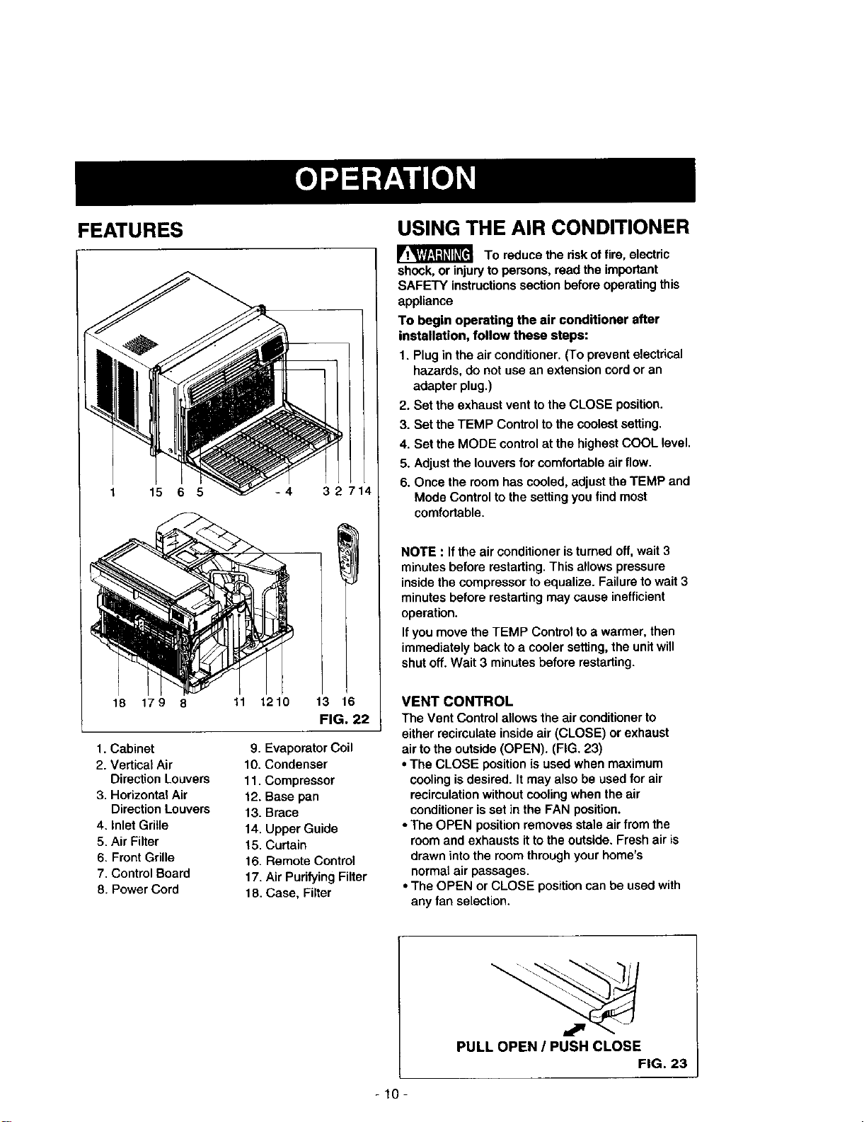
1. Cabinet
2. Vertical Air
Direction Louvers
3. Horizontal Air
Direction Louvers
4. Inlet Grille
5. Air Filter
6. Front Grille
7. Control Board
8. Power Cord
-4 32714
1210 13 16
FIG. 22
9. Evaporator Coil
10. Condenser
11. Compressor
12. Base pan
13. Brace
14. Upper Guide
15. Curtain
16. Remote Control
17. Air Purifying Filter
18. Case, Filter
USING THE AIR CONDITIONER
To reduce the risk of fire, electric
shock, or injury to persons, read the important
SAFETY instructions section before operating this
appliance
To begin operating the air conditioner after
installation, follow these steps:
1. Plug in the air conditioner. (To prevent electrical
hazards, do not use an extension cord or an
adapter plug.)
2. Set the exhaust vent to the CLOSE position.
3. Set the TEMP Control to the coolest setting.
4. Set the MODE control at the highest COOL level.
5. Adjust the louvers for comfor_.ble air flow.
6. Once the room has cooled, adjust the TEMP and
Mode Control to the setting you find most
comfortable.
NOTE : If the air conditioner is turned off, wait 3
minutes before restarting. This allows pressure
inside the compressor to equalize. Failure to wait 3
minutes before restarting may cause inefficient
operation.
If you move the TEMP Control to a warmer, then
immediately back to a cooler setting, the unit will
shut off. Wait 3 minutes before restarting.
VENT CONTROL
The Vent Control allows the air conditioner to
either recirculate inside air (CLOSE) or exhaust
air to the outside (OPEN). (FIG. 23)
• The CLOSE position is used when maximum
cooling isdesired. It may also be used for air
recirculation without cooling when the air
conditioner is set in the FAN position.
• The OPEN position removes stale air from the
room and exhausts it to the outside• Fresh air is
drawn into the room through your home's
normal air passages.
• The OPEN or CLOSE position can be used with
any fan selection.
PULL OPEN / PUSH CLOSE
FIG. 23
-10-
DISPLAY
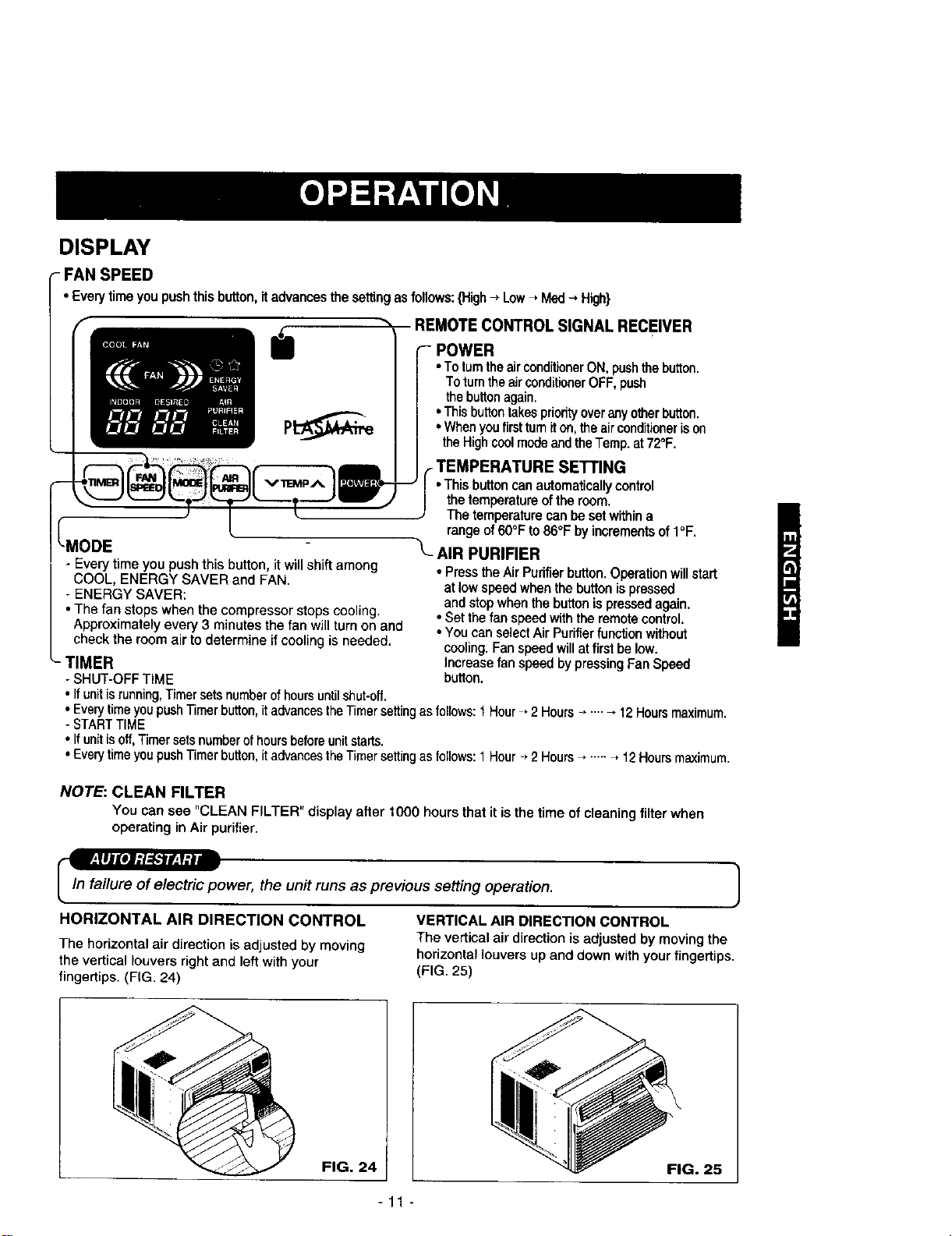
- FAN SPEED
• Everytimeyou pushthis button,itadvances the settingas follows:{High-, Low-, Med-, High}
REMOTE CONTROL SIGNAL RECEIVER
POWER
• To turnthe airconditionerON, pushthebutton.
To turnthe airconditionerOFF, push
the buttonagain.
• Thisbuttontakespriorityoverany otherbutton.
• Whenyoufirstturniton,the airconditioneris on
the Highcoolmode andtheTemp.at72°F.
- Every time you push this button, it willshift among
COOL, ENERGY SAVER and FAN.
- ENERGY SAVER:
• The fan stops when the compressor stops cooling.
I Approximately every 3 minutes the fan will turnon and
check the room air to determine if cooling is needed.
_- TIMER
- SHUT-OFF TiME
• If unit isrunning,Timer sets numberof hoursuntilshut-off.
,_E'n'ING
• This buttoncanautomaticallycontrol
the temperatureofthe room,
The temperaturecan be setwithina
range of60°F to86°F by incrementsof I°F.
"L_ AIR PURIFIER
• Press the Air Purifier button. Operation willstart
at lowspeed when the button is pressed
and stop when the button is pressed again.
• Set the fan speed withthe remote control.
• You can select Air Purifier function without
cooling. Fan speed will at first be low.
Increase fan speed by pressing Fan Speed
button.
• Everytime you pushTimerbutton, itadvances the Timersettingas follows: 1Hour • 2 Hours ...... 12 Hoursmaximum.
- STARTTIME
• If unit isoff, Timersets numberof hours beforeunit starts.
• Everytime you pushTimerbutton, itadvances the Timersettingas follows:1 Hour , 2 Hours ...... _ 12 Hoursmaximum.
NOTE: CLEAN FILTER
You can see "CLEAN FILTER" display after 1000 hours that it isthe time of cleaning filter when
operating in Air purifier.
_ower, the unit runs as previous setting operation. J
1
HORIZONTAL AIR DIRECTION CONTROL VERTICAL AIR DIRECTION CONTROL
The vertical air direction is adjusted by moving the
The horizontal air direction is adjusted by moving
the vertical louvers right and left with your horizontal louvers up and down with your fingertips.
fingertips. (FIG. 24) (FIG. 25)
FIG. 24
FIG. 25
-11 -
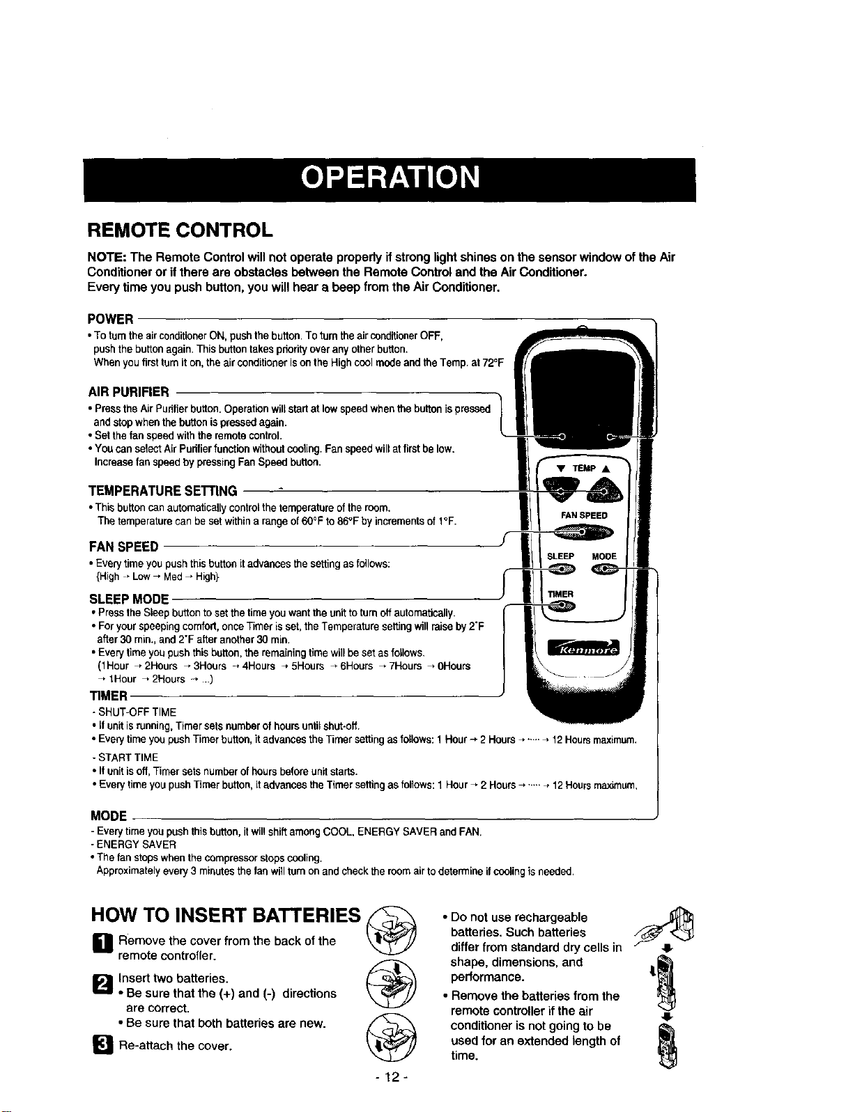
REMOTE CONTROL
NOTE: The Remote Control will not operate properly if strong light shines on the sensor window of the Air
Conditioner or if there are obstacles between the Remote Control and the Air Conditioner.
Eve_ time you push button, you will hear a beep from the Air Conditioner.
POWER
•ToturntheairconditionerON,pushthebutton.ToturntheairconditionerOFF,
pushthebuttonagain.Thisbuttontakespriorityoveranyotherbutton.
Whenyoufirstturniton,theairconditionerisontheHighcoolmodeandtheTemp.at72°F
AIR PURIFIER
• Pressthe AirPudfierbutton.Operabonwillstartat low speedwhenthe buttonis pressed
and stopwhen the button is pressedagain.
• Setthefan speedwiththe remotecontrol.
• Youcan selectAirPudfierfunctionwithoutcooling.Fan speed willat firstbe low.
Increasefan speed by pressingFan Speed button.
TEMPERATURE SE'I'rlNG
• Thisbuttoncanautomaticallycontrolthetemperatureoftheroom,
Thetemperaturecanbesatwithina rangeof60°Fto86°FbyincrementsofI°F.
FAN SPEED
•Everytimeyoupushthisbuttonitadvancesthesettingasfollows:
{High _Low_ Med_ High}
SLEEP MODE
• PresstheSleepbuttontosetthetimeyouwanttheunittoturnoffautomatically.
• Foryourspeepingcomfort,onceTimerisset,theTemperaturesettingwillraiseby2"F
after30rain. and2"Fafteranother30 rain.
• Every time you push thisbutton,theremaining time willbe set as follows.
(1Hour _ 2Hours _ 3Hours _ 4Hours _ 5Hours _ 6Hours _ 7Hours _ 0Hours
tHour _ 2Houra --_...)
TIMER
- SHUT-OFF TIME
• ff unitisrunning,Timersets numberof hoursuntil shut-off,
• Every timeyou pushTimerbutton,it advancesthe Timer setting as follows:1 Hour--, 2 Hours_ ..-. _ 12Hoursmaximum.
- START TIME
• If unit isoff,Timer sets numberof hoursbefore unitstarts.
• Everytime youpushTimer button,it advancesthe Timersettingas follows:1 Hour_ 2 Hours_ ....._ 12Hoursmaximum,
MODE
- Every timeyou pushthisbutton,it willshift amongCOOL, ENERGY SAVER and FAN.
- ENERGY SAVER
• The fan stopswhenthe compressorstopscooling.
Approximatelyevery3 minutesthefan willturn on and checkthe roomairto determineifcoolingis needed.
HOW TO INSERT BATTERIES
L1 Remove the cover from the back of the
remote controller.
Ip'_ Insert two batteries.
• Be sure that the (+) and (-) directions
are correct.
• Be sure that both batteries are new.
[]Re-attach the cover.
-12-
A
• Do not use rechargeable __
batteries. Such batteries
differ from standard dry cells in
shape, dimensions, and
performance. |
• Remove the batteries from the
remote controller if the air 41-
conditioner is not going to be _,_
used for an extended length of
time.
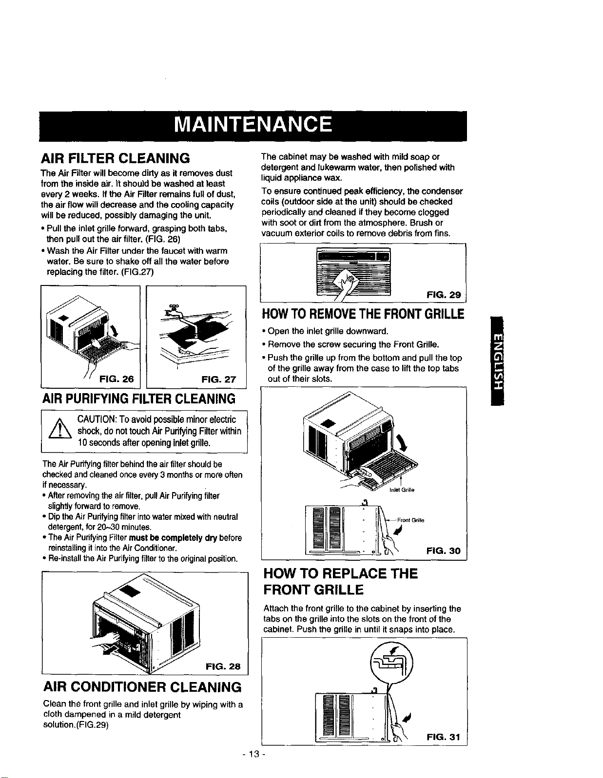
AIR FILTER CLEANING
The Air Filter will become dirtyas it removes dust
from the inside air. It should be washed at least
every 2 weeks. Ifthe Air Filter remains full of dust,
the air flow will decrease and the cooling capacity
will be reduced, possibly damaging the unit.
• Pull the inlet grille forward, grasping both tabs,
then pull out the air filter. (FIG. 26)
• Wash the Air Filter under the faucet with warm
water. Be sure to shake off all the water before
replacing the filter. (FIG.27)
FIG. 26 FIG. 27
AIR PURIFYING FILTERCLEANING
,,_ CAUTION:Toavoidpossibleminorelectric I
shock,donottouchAirPurifyingFilterwithin
10secondsafteropeninginletgrille.
The Air Purifying filter behind the airfiltershouldbe
checkedandcleanedonceevery3 monthsormore often
if necessary.
• Afterremoving theairfilter, pullAir Purifyingfilter
slightlyforward to remove.
• Dipthe Air Pudfyingfilter intowater mixed with neutral
detergent,for20.-,30minutes.
• The Air PurifyingFiltermust be completely dry before
reinstallingit intothe AirConditioner.
• Re-installthe AirPurifying filter tothe originalposition.
FIG. 28
AIR CONDITIONER CLEANING
Clean the front grille and inletgrille by wiping with a
cloth dampened in a mild detergent
solution.(FIG.29)
The cabinet may be washed with mild soap or
detergent and lukewarm water, then polished with
liquid appliance wax.
To ensure continued peak efficiency, the condenser
coils (outdoor side at the unit) should be checked
periodically and cleaned if they become clogged
with soot or dirt from the atmosphere. Brush or
vacuum exterior coils to remove debris from fins.
FIG. 29
HOWTO REMOVETHE FRONTGRILLE
• Open the inlet grille downward.
• Remove the screw securing the Front Gdlle.
• Push the grille up from the bottom and pull the top
of the grille away from the case to liftthe top tabs
out of their slots.
Inlet Grille
i_ Fr°nt Gnlk_
o1_ FIG. 30
HOW TO REPLACE THE
FRONT GRILLE
Attach the front grille to the cabinet by inserting the
tabs on the grille into the slots on the front of the
cabinet. Push the grille in until it snaps into place.
FIG. 31
-13-
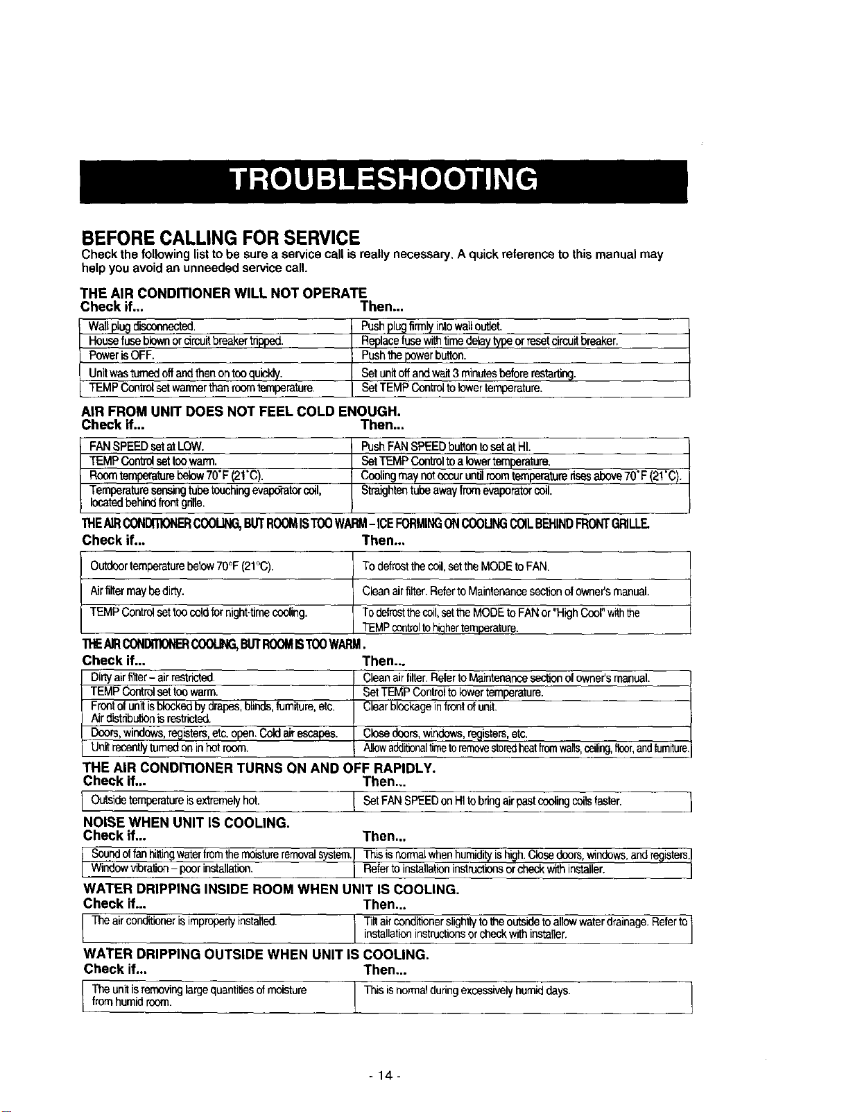
BEFORE CALLING FOR SERVICE
Check the following list to be sure a service call is really necessary, A quick reference to this manual may
help you avoid an unneeded service call.
THE AIR CONDITIONER WILL NOT OPERATE
Check if... Then,..
Waltplugdisconnected.
Housefuseblownorcircuitbreakertripped.
PowerisOFF.
Unitwasturnedoffandthenontooquickly.
TEMPCordrolsetwarmerthanroomtemperature.
Pushpl_ firmlyintowalloutlet.
Replacefusewithtimedelaytypeorresetcircuitbreaker.
Pushthepowerbutton.
Setunitoffandwait3minutesbeforerestarting.
SetTEMPControlto lowertemperature.
AIR FROM UNIT DOES NOT FEEL COLD ENOUGH.
Check if... Then..,
FANSPEEDsetatLOW.
TEMPCont_setfeewarm.
Roomtemperaturebelow70"F(2!"C)
Temperaturesensingtubetouchingevape_atorcoil,
locatedbehindfrontgrille.
PushFANSPEEDbuttontosetatHI.
SetTEMPControltoalowertemperature.
Coolingmaynotoccurunfilroomtemperaturerisesabove70"F(21'C).
Straightentubeawayfromevaporatorcoil.
THEAIR_ER COOLING,BUTROOMISTOOWAI_ - ICEFORMINGONCOOUNGCOILBEHINDFRONTGRILLE.
Check if... Then...
Outdoortemperaturebelow70°F(21°C). Todefrostthecoil,setthe MODEtoFAN.
Airfiltermaybedirty. Cleanairfilter.Referto Maintenancesectionof owner'smanual.
TEMPControlsettoocoldfornight-timecooling. Todefrostthecoil,setthe MODEtoFANor"HighCoor'withthe
TEMPcontroltohiqhertemperature.
"rI.EAIRCONDmoNERCOOUNG,BUTROOMISTO0WARM.
Check if... Then...
Dirtyairfilter- airrestricted. Cleanairfilter.RefertoMaintenancesectionofowner'smanual.
TEMPControlsettoowarm. SetTEMPControltolowertemperature.
Freerofunitisblockedbydrapes,blinds,furniture,etc. Clearblockageinfreerofunit.
Airdistributionisrestricted.
Doors,windows,registers,etc.open.Coldairescapes. Closedoors,windows,rngistars,eta
Unit recentlyturnedoninhotroom. AllowadditionaltimetoremovestoPedheatfromwalls,ceiling,f_, andfurniture
THE AIR CONDITIONER TURNS ON AND OFF RAPIDLY.
Check if.,. Then,,,
I Outsideternperatureisextremelybet' ! SetFANSPEEDonHItobringairpestcoolingc°ilsfaster" I
NOISE WHEN UNIT IS COOLING.
Check if... Then,..
I Soundoffanhittingwaterfmrnthemoisturerernovalsystem.Thisis_rmaLwhenhumidityishigh.Clesedoors,wthdows,andregisters.]
Wndowvibration- poorthsta]latlen. Refertoinstallationinstructionsorcheckwithinstaller, j
WATER DRIPPING INSIDE ROOM WHEN UNIT IS COOLING.
Check if,.. Then.,.
I Theairconditlonerisimproperiyinstalled j _tailaCOnondiitiOtnrerSl_ht(lYrtOhthecekOwUtS_i=densttOl_/_wwaterdrainage.Referto1
WATER DRIPPING OUTSIDE WHEN UNIT IS COOLING.
Check if... Then,..
Theunitisremovinglargequantitiesofmoisture Thisisnormalduringexcessivelyhumiddays.
fromhumidroom.
-14-
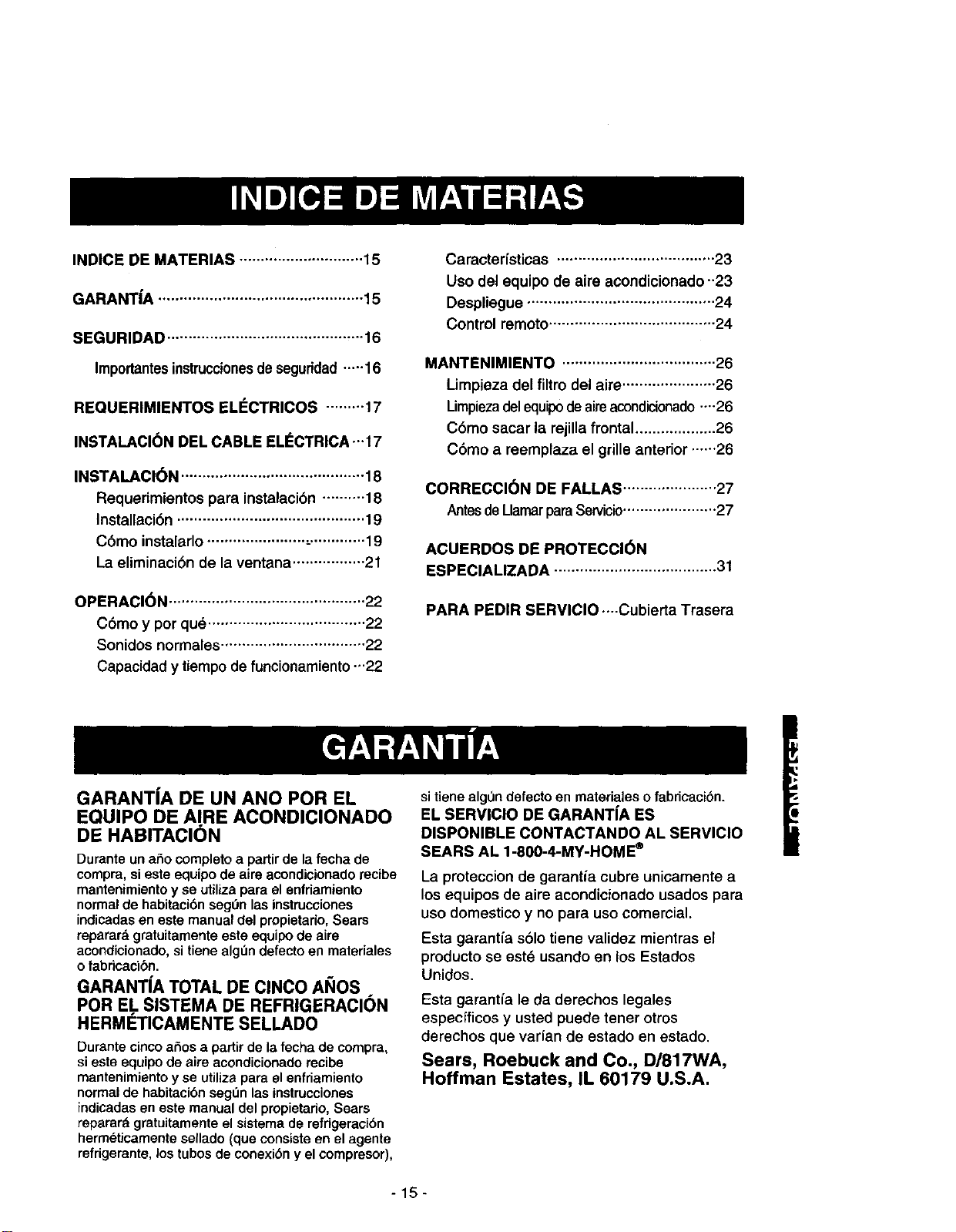
INDICE DE MATERIAS ............................. 15
GARANT|A ................................................ 15
SEGURIDAD .............................................. 16
Importantesinstruccionesde seguridad.....16
REQUERIMIENTOS ELECTRICOS ......... 17
INSTALAClON DEL CABLE ELI_CTRICA ...17
INSTALACl6N ........................................... 18
Requerimientos para instalaci6n .......... 18
Installaci6n ............................................ 19
C6mo instalarlo ....................... ,-............. 19
La eliminaci6n de la ventana ................. 21
OPERACION .............................................. 22
C6mo y por qu_ ..................................... 22
Sonidos normales .................................. 22
Capacidad y tiempode funcionarniento...22
Caracterfsticas ..................................... 23
Uso del equipo de aire acondicionado-23
Despliegue ............................................ 24
Control remoto ....................................... 24
MANTENIMIENTO .................................... 26
Limpieza del filtro del aire ...................... 26
Limpiezadelequipodeaireacondicionado....26
C6mo sacar la rejilla frontal................... 26
C6mo a reernplaza el grille anterior ......26
CORRECCION DE FALLAS ...................... 27
AntesdeLlamarparaSewicio...................... 27
ACUERDOS DE PROTECCl6N
ESPECIALIZADA ...................................... 31
PARA PEDIR SERVICIO ..--Cubierta Trasera
GARANTJA DE UN ANO POR EL
EQUIPO DE AIRE ACONDICIONADO
DE HABITACI6N
Durante un afio completo a partir de la fecha de
compra, si este equipo de aire acondicionado recibe
mantenimiento y se utiliza para el enfdamiento
normal de habitaci6n seg0n las instrucciones
indicadas en este manual del propietario, Sears
reparard gratuitamente este equipo de aire
acondicionado, si tiene algen defecto en materiales
o fabricaci6n.
GARANT[A TOTAL DE CINCO AltOS
POR EL SISTEMA DE REFRIGERACI(_N
HERMETICAMENTE SELLADO
Durante cinco aries a partir de la fecha de compra,
si este equipo de aire acondicionado recibe
mantenimiento y se utiliza para el enfriamiento
normal de habitaci6n segL_nlas instrucciones
indicadas en este manual del propietario, Sears
reparar& gratuitamente el sistema de refrtgeraci6n
herm6ticamente sellado (que consiste en el agente
refrigerante, los tubos de conexi6n y el compresor),
sitiene alg0n defecto en materiales o fabdcaci6n.
EL SERVIClO DE GARANT|A ES
DISPONIBLE CONTACTANDO AL SERVICIO
SEARS AL 1-800-4-MY-HOME ®
La proteccion de garantia cubre unicamente a
los equipos de aire acondicionado usados para
uso domestioo y no para uso comercial.
Esta garantfa s61otiene validez mientras el
producto se est6 usando en los Estados
Unidos.
Esta garantia le da derechos legales
especfficos y usted puede tener otros
derechos que varfan de estado en estado.
Sears, Roebuck and Co., D/817WA,
Hoffman Estates, IL 60179 U.S.A.
-15-
IMPORTANTES INSTRUCCIONES DE SEGURIDAD
Las siguientes instrucciones de seguridad le indicardn c6mo usar su equipo de airs acondieionedo de
habitacibn para evitar dafios para usted mismo y papa su EQUIPO DE AIRE ACONDICIONADO.
POR SU SEGURIDAD
No almacene ni use gasolina u otros vapores y
I(quidos inflamables cerca de dste o cualquier OtTO
electrodom_stico. Lea las etiquetas de los
productos para ver si contienen advertencias sobre
et cardcter inflamable de los mismos y otras
advertencias.
PARA PREVENIR ACCIDENTES
Pare reducir el riesgo de incendios, descargas
el_ctdcas o lesiones personales al usar su equipo
de aire acondicionado, tome tas precauciones
bdsicas, entre las que estdn las siguientes:
• Aseg_rese de que la alimentacibn el_ctrica sea la
apropiada para el modelo que usted ha elegido.
• Si el equipo de airs acondicionado debe instatarse
en una ventana, a usted probablemente le
conviene limpiar primero arnbos lados del vidrio.
Si la ventana es del tipo de tres paneles con un
panel incluido de pantalla, le conviene saear la
ventana completamente antes de la instalacibn.
• Aseg_rese de que el equipo de aire
acondicionado ha sido instalado correctamente y
con seguridad seg_n se sefiala en las
instrucciones separadas de instalacibn que vienen
en este manual Conserve este manual y las
instrucciones de instalacibn para usarlos
posibiemente en el futuro al sacar o volver a
instalar esta unidad.
• Use guantes al manejar el equipo de airs
acondicionado, tenga cuidado para evitar cortadas
con tas afiladas aletas metdlicas que se hanan en
los serpentines frontales y posteriores.
INFORMACI(_N ELECTRICA
En la placa de serie del fabricante se indica cudl es
la capacidadel_trica nominal completa de su nuevo
equipo de aimacondicionado !oamhabitaci6n. Consulte
eela placa cuando vaya avedflcar los requedmientos
el_:tdcos.
• Aseg_resede que el equipode aim acondicionado
tenga una conexi6n cormela a tierra. Para reduciral
mfnimo los riesgosde descar_as el_o'icas e incendio,
es importante conectar el equlpo correctamente a tierra.
El cord6n de alimentad6nelL=elricaestd equipado con
un enchufe de ires espigascon conexi6n a tierra para
protegede contra desgos de descargaselL,ctricas.
• Su equipo de aim acondicionado debe enchufarse en
unatoma de cornentede pared que tenga una conexi6n
correcta atierra. Silatomade comente de paredque
usted piensa usar no estd conectada correctamente a
tierra o no est_ protegida con un fusible de acci6n
retardada o con un interruptor de circuito, haga queun
electricistacalificado le instaie latoma de corriente de
pared en forma correcta.
• No ponga a funcionar elequipo de aim acondicionado
con unacubierta protectora exteriorencima. Esto podrfa
ccasionar dar3esmecdnicos dentro del airs
acondicionade.
• NOuse un cable de extensidn ni un enchufe
adaptador.
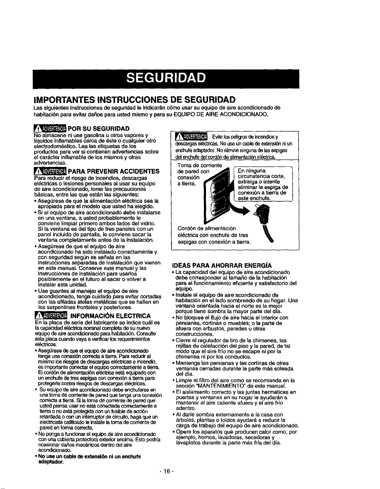
Evitelos peligrosde incendiosy
descargasslL_ricas. No useuncablede extensi6nniun
enchufeadaptador.Noelimineningunadelas espigas
delenchufedelcord6nde alimentaci6nel_trica.
Tomade corriente
depared con
conexi6n
a tierra.
En ninguna
circunstancia corte,
extraiga o intente
eliminar la espiga de
conexibn a tierra de
este enchufe.
Cordbn de alimentacibn
el_ctrica con enchufe de tres
espigas con conexi6n a tierra.
\
IDEAS PARA AHORRAR ENERG|A
• La capacidad del equipo de a|re acondicionado
debe corresponder al tamafio de la habitacibn
para el funcionamiento eficiente y satisfactedo del
equipo.
•Instale el equipo de aire acondicionado de
habitaci6n en el lado sombreado de su hogar. Una
ventana orientada hacia el norte es la mejor
porque tiene sombra (a mayor parts del dfa.
• No bloquee el flujo de airs hacia el interior con
persianas, cortinas o muebles; o la parts de
afuera con arbustos, paredes u otras
construcciones.
• Cierre el regulador de tiro de la chimenea, las
rejillas de calefacci6n del piso y la pared, de tal
mode que el aire frio no se escape ni por la
chimenea ni por los conductos.
• Mantenga las persianas y las cortinas de otras
ventanas cerradas durante la parte rods soleada
del dia.
• Limpie el flltro det airs eomo se recomienda en la
secci6n "MANTENIMIENTO" de este manual.
• El aislamiento correcto y las juntas herm_ticas en
puertas y ventanas en su hogar le ayudardn a
mantener el airs caliente afuera y el airs frfo
adentro,
• AI darle sombra externamente a la easa con
drboles, plantas o totdos ayudard a reducir la
carga de trabajo del equipo de airs acondicionado.
• Opere los aparatos que producen calor como, pot
ejemplo, hornos, lavadoras, secadoras y
lavap(atos durante la parts m_s fri'a del dfa.
-16-
RESPETE TODOS LOS C6DIGOS Y
REGLAMENTOS.
BAJO NINGUNA CIRCUNSTANCIA CORTE,
QUITE 0 EVITE EL USO DE LA CONEXl6N A
TIERRA DEESTA CLAVIJA.
ESTE APARATO NECESITA SER CONECTADO A
TIERRA.
Se requiere una alimentaci6n el6ctrica CA,
adecuadamente conectada a tierra con unfusible de
15A, de 60 Hz y de 230/208 V. Se recomienda un
fusible de retardo o un disyuntor de circuito que
alimente solamente a este aparato.
NO USECABLE ELECTRICO DE EXTENSI6N.
METODO RECOMENDADO DE CONEXI(_N A
TERRA
Porsu propiaseguridadesteaparatodebe
conectarsea tierra.Esteaparatoviene equipado
conun cablede alimentaci6n y unaclavija de tres
terminales. Para reducir al mdximo el peligro de
choque el6ctrico, el cable debe estar conectado a
una conexi6n de pared con conexi6n a tierra,y esta
conexi6n debe hacerse de acuerdo con la L_ltima
edici6ndel C6digo Electrico Nacional (ANSI/NFPA
70),asi como con losc6digos y reglamentos
locales. Si no existe una conexibn de pared
adecuada, el cliente tiene la responsabilidad y la
obligacibn de mandar instalar, con un electricista
calificado, una conexi6n de pared adecuada de tres
terminales con conexibn a tierra.
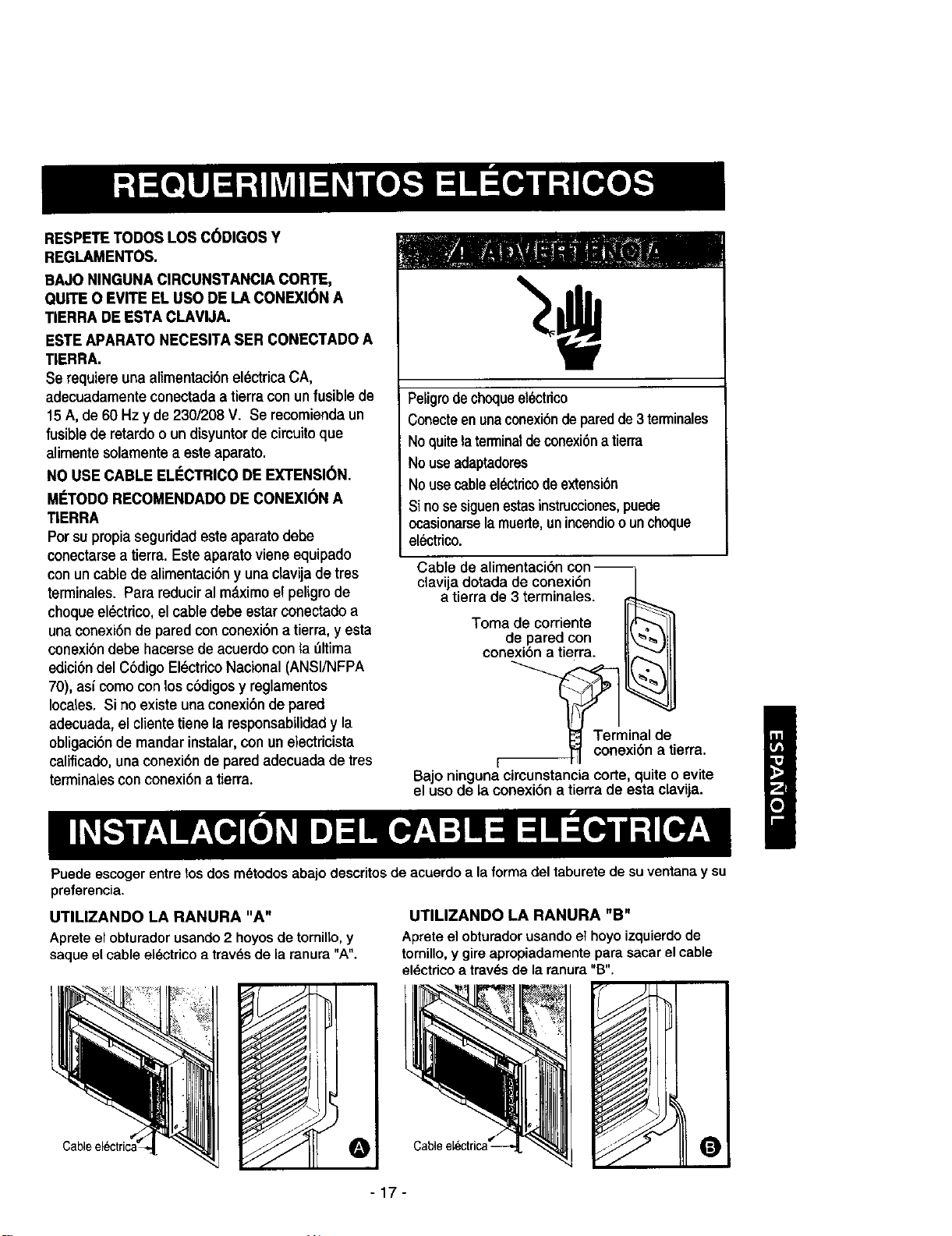
Peligrodechoqueel_ctrico
Conecteenunaconexi6nde paredde3 terminales
Noquitela terminaldeconexi6na tierra
Nouseadaptadores
Nousecableel6ctricode extensi6n
Si no sesiguenestasinstrucciones,puede
ocasionarsela muerte,unincendiooun choque
electrico.
Cable de alimentaci6n con
clavija dotada de conexi6n /
a tierra de 3 terminales.
Toma de corriente IIF'7- ]I
de pared con II ', IIII
conexi6n a tierra _
_Terminal de
I '_ conexi6n a tierra.
Bajo ninguna circunstancia corte, quite o evite
el uso de la conexi6n a tierra de esta clavija.
Puede escoger entre los dos m_todos abajo descritos de acuerdo a la forma del taburete de su ventana y su
preferencia.
UTILIZANDO LA RANURA "A"
Aprete el obturador usando 2 hoyos de tomilto, y
saque el cable al_ctrico a trav_s de la ranura "A".
UTILIZANDO LA RANURA "B"
Aprete el obturador usando et hoyo izquierdo de
tornillo, y gire apropiadamente para sacar el cable
eldctrico a travds de la ranura "B".
!
0
4"
-17-
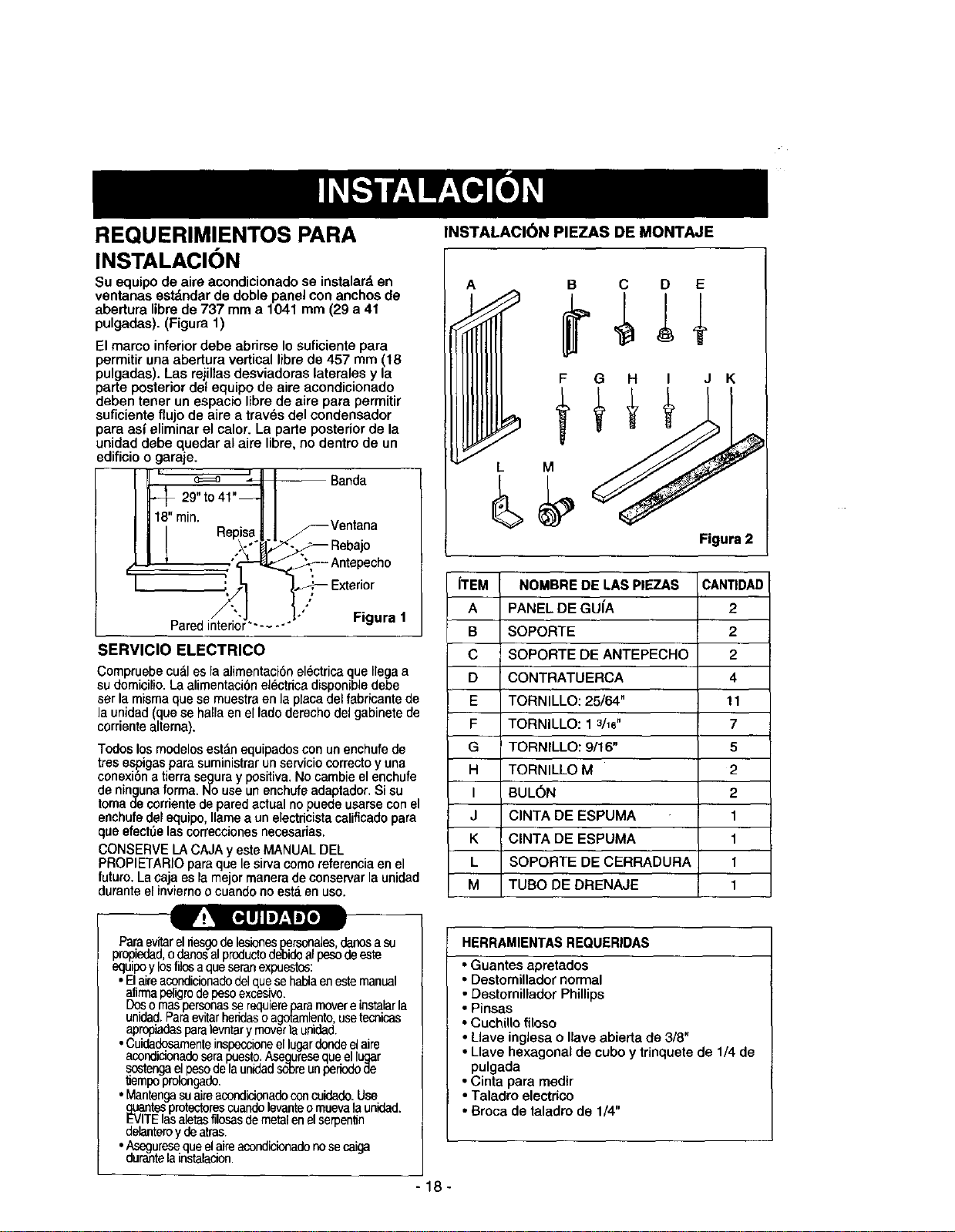
REQUERIMIENTOS PARA
INSTALACION
Su equipo de aire acondicionado se instalar_,en
ventanas estdndar de doble panel con anchos de
abertura libre de 737 mm a 1041 mm (29 a 41
pulgadas). (Figura 1)
El marco inferior debe abrirse Io suficiente para
permitir una abertura vortical libre de 457 mm (18
pulgadas). Las rejillas desviadoras laterales y la
parte posterior del equipo de aire acondicionado
deben tener un espaoio libre do aire para permitir
suficiente fiujo de aire a trav6s del oondensador
pare asi eliminar el color. La parte posterior de la
unidad debe quedar al aire libre, no dentro de un
edificio o garaje.
' e==o _ Banda
29"t0 41"_._ ]
min. Re [I _--Ventana
Pi_'a"i_"1_-,_ - Rebajo
•_- Antepecho
"'J l°'°} Figura
_ "_,,I1 t_ Exteri°r
/
Pared interior...... " 1
SERVICIO ELECTRICO
Compruebe cu£1es la alirnentaci6n electrica que Ilega a
sudornicilio. La alimentaci6n el6ctdca disponible debe
ser la misrna que se rnuestra en la pleca del fabricante de
la unidad (que se halla en el lado derecho del gabinete de
corriente altema).
Todos los modelos estan equipados con unenchufe de
tres espigas para suministrar un servicio correcto y una
conexi6n atierra seguray positive. No cambie el enchufe
de ninguna forma. No use un enchufe adaptador. Si su
torna de corriente de pared actual no puede usarse con el
enchufe del equipo,lame a un electdcista calificado para
que efectQelas correcciones necesarias.
CONSERVE LA CAJA y este MANUAL DEL
PROPIETARIO pare que le sirva como referencia en el
futuro. Lacajaas la mejor manera de conserver la unidad
durante el inviernoo cuando no esta an uso.
INSTALACI(_N PIE/AS DE MONTAJE
C D E
H I J K
Figure 2
ITEM NOMBRE DE I.AS PIEZAS CANTIDAD
A PANEL DE GUfA 2
B SOPORTE 2
C SOPORTE DE ANTEPECHO 2
D CONTRATUERCA 4
E TORNILLO: 25/64" 11
F TORNILLO: 1 3/16" 7
G TORNILLO: 9/16" 5
H TORNILLO M 2
I BUL(SN 2
J ClNTA DE ESPUMA 1
K ClNTA DE ESPUMA 1
L SOPORTE DE CERRADURA 1
M TUBO DE DRENAJE 1
HERRAMIENTAS REQUERIDAS
Pa.raevitarelnesgo de lesionespersena_es,danosa su
propledad,o dano,_al productodeff_oalpesodeeste
equipoy losfilosaqueseranexp_esto_:
•Elaireasendicionadodelquesehablaenestemanual
afirrnapeligrodepesoexcesivo.
Dosornaspersonasserequiereparemovereinstalarla
unided.Paraevitarheridasoagotamlentousetecnicas
apropadespara evntary moverlaundad.
•Cuidedosarnenteinspeccioneel lugardendeel ale
acondidonadeserapuesto.Asequresequeel lugar
sostengaelpesode launidadsol)reunperiodode
tempo prolongade.
• Mantengasuaireacondicionadoconcuidade.Use
guanlesprotectorescuandolevanteo muevala unidad.
EVITElasaletasfilosasdernetalenelserpenln
delanteroy deatras
•,_seguresequeel aireacondicionadonose caiga
durantelainstalacion.
• Guantes apretados
• Destornillador normal
• Destornillador Phillips
• Pinsas
• Cuchllo filoso
• Llave inglesa o Ilave abierta de 3/8"
• Llave hexagonal de cubo y trinquete de 1/4 de
pulgada
• Cinta para medir
• Taladro electrico
• Broca de taladro de 1/4"
-18-
INSTALACION
Escoja un lugarque Is permita Ilevar el aire frio al drea
que desea. Lasventanas que se usen para la
instalaci6n deben tener la msistancia suficientapara
soportarel pesodel equipo de aire acondicionado.Una
buena instaiaci6ncon atenci6n especiala lacorrecta
posici6nde la unidad disminuirdla probabilidadde que
sea necesario efectuar reparaciones.
Cuando se desea enfriarmas de una habitaci6n,la
instalaci6nes muy importantapuesto que el aire fdo no
dobla esquinas. Para enfriarsus habitaciones,el aire
fifo debe desplazarse desde el equipo de aire
acondicionadoen una trayectona recta.
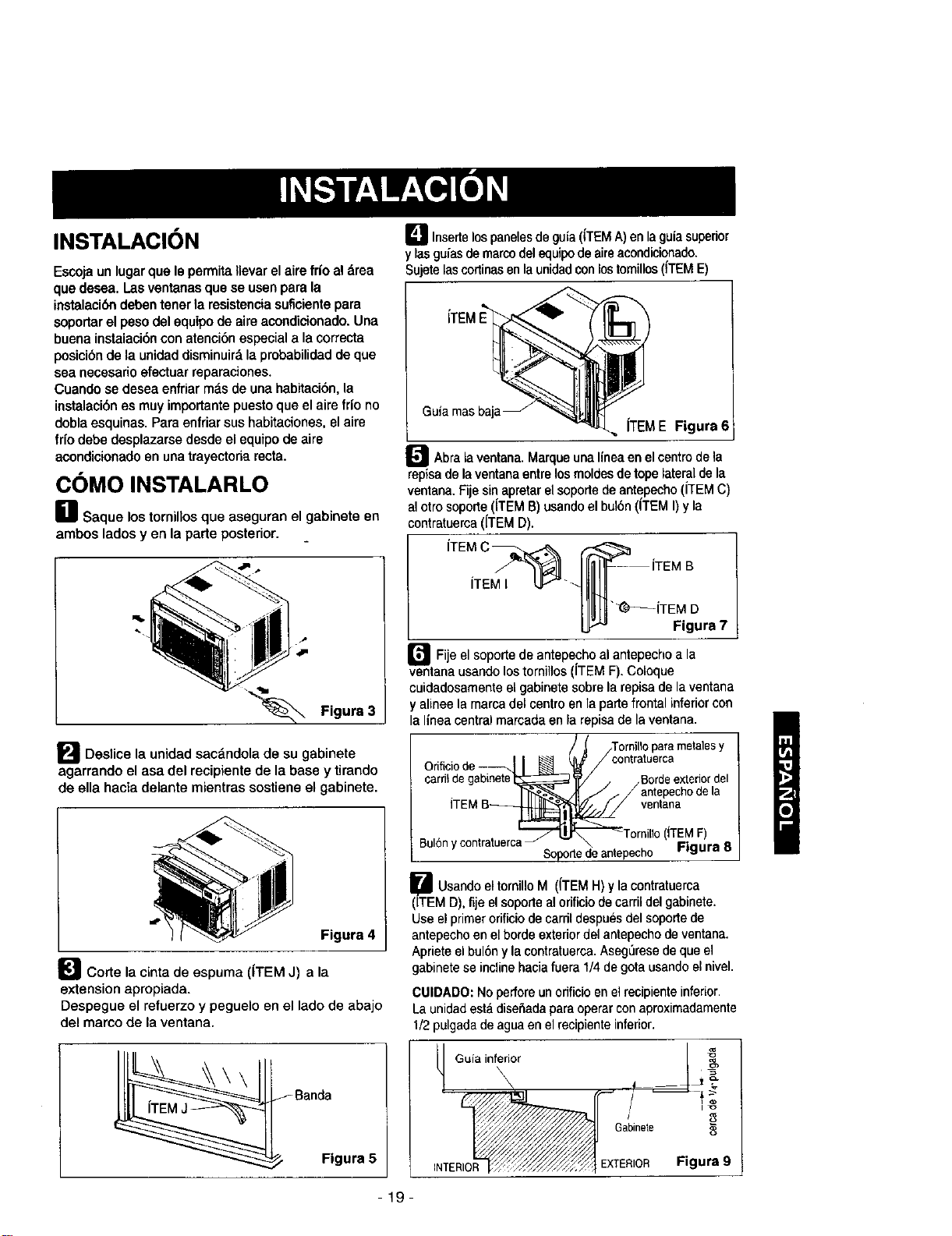
COMO INSTALARLO
_1 Saque lostomillos que aseguran el gabinete en
ambos lados y en la parte posterior.
Figura 3
[] Deslice la unidad sacdndola de su gabinete
agarrando el asa del recipienta de la base y tirando
de ella haeia delante mientras sostiene el gabinete.
Figura 4
_J Corte la cinta de espuma ((TEM J) a la
extension apropiada.
Despegue el refuerzo y peguelo en el lado de abajo
del marco de la ventana.
Figura 5
D Insertelos panelesde guia (iTEMA)en la guiasuperior
y lasguias de marcodelequipode aireacondici,onado.
Sujetelascortinas enla unidad conlos tomillos (ITEME)
Guia masbaj
iTEME Figura 6
_J Abrala ventana.Marqueuna lineaen elcentrede la
repisa de laventana entre los moldes de tope lateral de la
ventana, Fie sin apretar el soporte de antepecho (iTEM C)
al otro soporte iTEM B) usandoel bulbn (iTEM I)y la
contratuerca (ITEM D).
iTEM I
r_Fi e el soporte de antepecho antepecho a
al la
ventana usando los tornillos ( TEM F). Coloque
cuidadosamente el gabinete sobre la repisa de la ventana
y alinee la mama del centro en la parte frontal inferior con
la linea central marcada en la repisa de la ventana.
/)[ /Tornillo para metalesy
Orificio de --_!_'J contratuerca
carril degab_(i_j/ _Borde extedor del
. r,l-_=_-_,=/_ j / / antepecho de la
ITEM B_To_entana
illo(iTEM F)
Bul6n y contratuerca_ -- \ =i""ra 8
Soporte de antepecho "_"
U Usandoel tornillo M (iTEMH) y la contratuerca
(ITEM D),fije el soporte al orificio de carril delgabinete.
Use el primerorificio de carril despues del soportede
antepechoen el borde exterior del antepecho de ventana.
Aprieteel bul6ny la contratuerca.Aseg_rese deque el
gabinete seincline hacia fuera 1/4 de gota usando el nivel.
CUIDADO: Noperfore un odficioen el recipienteinferior.
La unidadestddise5adaparaoperarconaproximadamente
1/2pulgadadeaguaan elrecipienteinferior.
Guia inferior
INTERIO EXTERIOR Figura 9
-19-
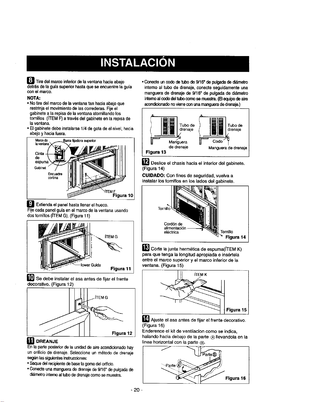
I_ Tire delmarcoinferior de laventana haciaabajo
detrdsde lagufasuperiorhastaque seencuentrola gufa
con el marco.
NOTA:
• Notiredel marcode la ventanatan haciaabajoque
restrinjael movimiento de lascorrederas.Fijeel
gabinetea la repisade laventana atornillandolos
tomillos (iTEM F)a trav_sdelgabineteen la repisade
laventana.
• El gabinetedebe instalarse1/4 de gota de el nivei,hecia
abajo yhaciafuera.
Marcode
Cinta
de
Encuadre
CO,ha
'iTEM F
Figura 1
_ Extiendaelpanel hastaIlenarelhueco.
Fijecada panelgufaen elmarco de la ventanausando
dos tomiilos(ITEM G). (Figura 11)
ITEM G
Figura 11
_l_se debe instalar el asa antes de fijar el frente
deeorativo. (Figura 12)
Figura 12
_1 DREANJE
En laparteposteriorde la unidadde aim acondicionadehay
un orificiode drenaje,Seteccione un mdtode de drenaje
segdnlassiguientesinstrucciones:
• Saquedelrecipientedebasela gomadelorfficio.
• Conecteunamanguerade dmnaje de 9/16" depulgadade
di_metrointemoaltubode drenajecomosemuestra.
• Conecteun codo de tubode 9/16" de pulgadade didmetro
intemo al tubo de dronaje, conecte seguidamente una
manguera de drenaje de 9/16" de pulgadade didmetro
intemoal codedeltubocomose muestra.(B equipode aire
acondicionadenovienecon unarnangueradedrenaje.)
_angudTUbo de _ Tubo de
ri_aje I_ renaje
de drenaje Manguera de drenaje
Flgura 13
[] Deslice el chasis hacia el interior del gabinete.
(Figura 14)
CUlDADO: Con fines de seguridad, vuelva a
instalar lostornfflosen los lados del gabinete.
Cord6n de
alimentaci6n --
electrica
Tornillo
Figura 14
B Corte la junta hermdtica de espuma(iTEM K)
para que tenga la Iongitud apropiada e ins6rtela
entre el marco superior y el marco inferior de la
ventana. (Figura 15)
Figura 15
_] Ajuste el asa antes de fijar el frente decorativo.
(Figura 16)
Enderence el kit de ventilacion oomo se indica,
halando hacia debalo de la parte ® Ilevandola en la
linea horizontal con ia parle ®.
Figura 16
- 20 -
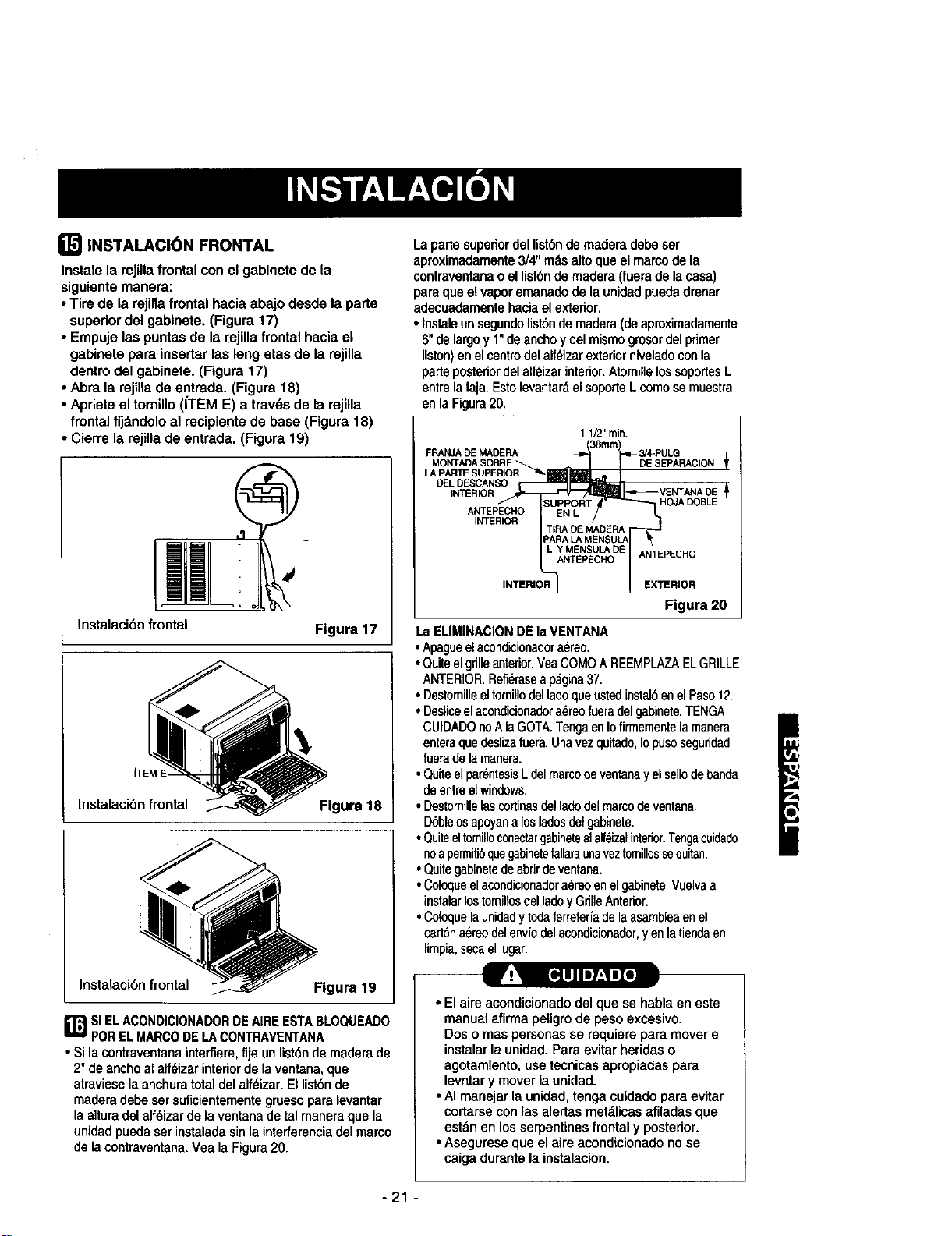
INSTALACION FRONTAL
Instale la rejUlafrontal con el gabinete de la
siguiente manera:
• Tire de la rejilla frontal hacia abajo desde la parte
supedor del gabinete. (Figura 17)
• Empuje las puntas de la rejilla frontal hacia el
gabinete pare insertar las leng eras de la rejilla
dentro del gabinete. (Figure 17)
• Abra la rejilla de entrada. (Figure 18)
• Apdete el tomillo (ITEM E) a trav_s de la rejilla
frontal fijdndolo al recipiente de base (Figura 18)
• Cierre la rejilla de entrada. (Figure 19)
Instalacibn frontal
Figura 17
Inatalacibn frontal Flgura 18
Instalaci6n frontal Figura 19
ir_j si ELACONDICIONADORDEAIREESTABLOQUEADO
PORELMARCODELACONTRAVENTANA
• Sila contraventanainterfiere,fije unlist6nde madera de
2"de anchoal alf_izarinteriorde laventana,que
atraviesela anchuratotaldel alf_izar.El list6nde
madera debesersuficientementegruesopara levantar
la alturadelalfdizar de laventana de tal maneraque la
unidedpuedaser instaladasinla interferenciadel marco
de lacontraventana.Vea laFigura20.
La porte supenordei list6nde madera debeser
aproximadamente3/4"rods altoque el marcode la
contraventanao el list6nde madera (fuera de lacasa)
paraque el vaporemanadode la unidadpuededrenar
adecuadamentehaciael extader.
• Instaleunsegundelist6nde madera(de aproximademente
6"de largoy 1"deanchoy del mismogrosordelprimer
liston)en elcentrodel alf_izarexteriorniveladoconla
parleposteriordel alfeizarinterior.AtomilielossoportesL
entrelafaja. EstolevantaraelsoporteL comose muestra
en la Figura20.
1 1/2" rain.
[
MONTADASOanE _ _ I 1 DESEPARACION T
LAPARTESUPERIOR
DELDESCANS_
INTERIOR _VENTANA DE _
ANTEPECHO HOJADOBLE
INTERIOR
ANTEPECHO
ERIOR
Figura 20
La ELIMINACIONDE laVENTANA
• Apagueelacondiciocodora_reo.
• Quiteelgrilleanterior.VeaCOMOAREEMPLAZAELGRILLE
ANTERIOR.Refi_rasea pdgina37.
• Destomilleeltomillodelladequecotedinstal6anelPaso12.
• Desliceelacondicionadoraereofcoradelgabinote.TENGA
CUIDADOnoAlaGOTA.TengaenIofirmementela manera
enteraquedeslizafuera.Unavezquitado,Iopusoseguridad
fueredelamanera.
•QuiteelparentesisLdelmarcodeventanay elsellodebanda
deentreelwindows.
• Destomillelascortinasdelladedelmarcodevantana.
D6blelosapoyana losladosdelgabinete.
•QuiteeltomilloconectargabinetealalfeizaFinterior.Tengacuidado
noa permiti6quegabinetefallaraunaveztornillossequitan.
• Quitegabinotedeabrirdevantana.
• Coloqueelacondicionadora_reoenelgabinete.VueIvaa
instalarlostomillosdelladoy GrilleAnterior.
• Coloquelauniriadytodaferreteriadelaasambleaen el
cart6nabreodelenviodelacondicionador,yan latiandaan
limpia,secaellugar.
• El aire acondicionado del que se habla en este
manual afirma peligro de peso excesivo.
Dos o mas personas se requiere para mover e
instalar la unidad. Para evitar heddas o
agotamlento, use tecnicas apropiadas para
levntar y mover la unidad.
• AI manejar la unidad, tenga cuidado para evitar
cortarse con las alertas metdlicas afiladas que
est_n en los serpentines frontal y posterior.
• Asegurese que el aire acondicionado no se
caiga durante la instalaoion.
-21 -
COMO Y POR QUE
Su equipo de aire acondicionado de habitacibn
brinda las siguientes funciones para hacer que la
vida en climas cdlidos sea mds confortable:
• Enfda y hace cimular el aire por la habitacibn
• Disminuye la humedad eliminando la humedad
excesiva.
• Filtra el polvo, el sucio y algunas impurazas
transportadas an el aire del clima veraniego.
El equipo de aire acondicionado realiza estas
funciones haeiendo pasar el aim del medio
ambiente a trav_s de un filtro que atrapa las
particutas de polvo y sucio. El aire pasa entonces
por un serpentfn de enfriamiento que refrigera el
aire y elimina el exceso de humedad. El misrno aire
regresa entonces al enfdador, secador y limpiador
del aire del ambiente. La humedad extmfda del aire
ambiente es Ilevada al exterior y evaporada.
Su aire acondicionado est_ diseSado para operar y
suministrar una enorme potencia de enfriamiento.
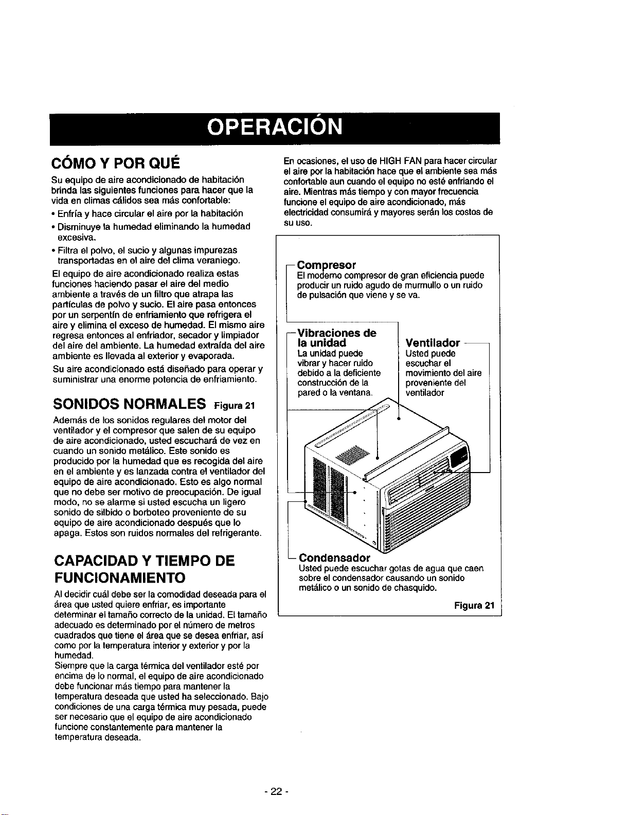
SONIDOS NORMALES Figura21
Ademds de lossonidos regulates del motor del
ventilador y el compresor que salen de su equipo
de aire acondicionado, usted escuchard de vez en
cuando un sonido metalico. Este sonido es
producido pot la humedad que es recogida del aire
en el ambiente yes lanzada contra el ventilador del
equipo de aire acondicionado, Esto es algo normal
que no debe ser motivo de preocupaci6n. De igual
modo, no se alarme si usted escueha un ligero
sonido de silbido o borboteo proveniente de su
equipo de aire acondicionado despu_s que Io
apaga, Estos son ruidos normales del refrigerante.
CAPAClDAD Y TIEMPO DE
FUNCIONAMIENTO
AI decidir cudldebe ser la comodidad deseada para el
_rea que usted quiere enfriar, es imporlante
determinar el tamaSo correcto de la unidad. El tamaSo
adecuado es determinado por el n_mero de metros
cuadrados que tiene el drea que se desea enfriar, asi
como por latemperatura interior y exterior y por la
humedad.
Siempre que la carga t(_nnica del ventilador est_ por
encima de Io normal, el equipo de aire acondicionado
debe funcionar mds tiempo para mantener la
temperatura deseada que usted ha seleccionado. Bajo
condiciones de una carga t6rmica muy pesada, puede
ser necesario que el equipo de aire acondicionado
funcione constantemente para mantener la
temperatura deseada.
En ocasiones, el uso de HIGH FAN para hacer circular
el aim pot la habitacibnhace que el ambiente sea m_ts
confortableaun cuando el equipo noest_ enfriando el
aire. Mientras mds tiempo y con mayor frecuencia
funcione el equipo de aire acondicionado,mds
electricidadconsumirdy rnayoresserdn los costosde
su usa.
- Compresor
Elmodemocompresordegraneficienciapuede
producirunruidoagudode murmunoounruido
depulsaci6nquevieney seva.
--Vibraciones de
la unidad
Launidadpuede
vibrary hacerruido
debidoa la deficiente
constmccibnde la
paredo laventana.
Ventilador --
Usted puede
escuchar el
rnovimientodel aire
proveniente del
ventilador
Condensador
Usted puede escuehar gotasde agua que caen
sobre el condensador causando unsonido
metdlico o unsonido de ehasquido.
Figura21
- 22 -
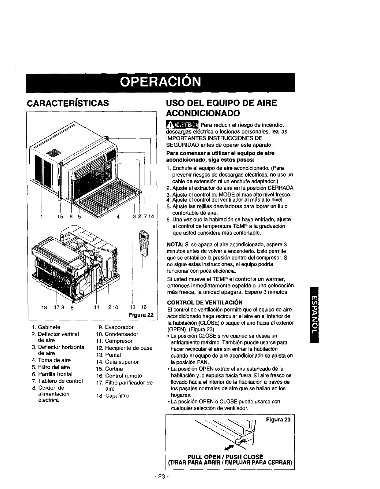
CARACTER TICAS
15 6 5 4 - 32714
18 17 9 8 11 1210 13 16
Figura 22
1. Gabinete
2. Deflector vertical
de aire
3. Deflector horizontal
de aire
4. Toma de aire
5. Filtro del aire
6. Parrilla frontal
7. Tablero de control
8. Cord6n de
alimentaci6n
el_ctrica
9. Evaporador
10. Condensador
11. Compresor
12. Recipiente de base
13. Puntal
14. Gufa superior
15. Cortina
16. Control remoto
17. Filtro purificador de
aire
18. Caja filtro
USO DEL EQUIPO DE AIRE
ACONDICIONADO
Para reducir el riesgo de incendio,
descargas el_ctdca o leeiones personales, lea las
IMPORTANTES INSTRUCClONES DE
SEGURIDAD antes de operar este aparato.
Para comenzar a utilizar el equipo de aire
acondicionado, siga estos pasos:
1. Enchufe el equipo de aire acondlcionado. (Para
prevenir riesgos de descargas elL=ctdcas,no use un
cable de extenei6n ni un enchufe adaptador.)
2. Ajuste el extractor de aim en la posici6n CERRADA
3. Ajuste el controlde MODE al mas alto nivel fresco.
4. Ajuete el controldel ventilador al rods alto nivel.
5. Ajuete las rejillasdeeviadoras para Iograr unflujo
confortable de aire.
6, Una vez que la habitaci6nse haya enfriado, ajuste
el controlde temperafura TEMP a la graduaei6n
que usted eoesidere mds confortable.
NOTA: Si se apaga el aire acondicionado, espere 3
minutos antes de volver a encenderlo. Eeto permite
que se estabilice la presi6n dentro del compresor. Si
nosigue eetas instrucciones,el equipo podrfa
funcionar con poca eficiencia.
Si usted mueve el TEMP el control a un warmer,
entoneee inmediatamente espalda a una eolocacibn
mds fresca, la unidad apagard. Espero 3 minutos.
CONTROL DE VENTILACI_N
El control de ventilaci6npermite que el equipode aire
acondicionado haga recimularel aire en el interiorde
la habitaci6n (CLOSE) o saque el aire hacia e! exterior
(OPEN). (Figura 23)
• La posici6n CLOSE sirve cuando se desea un
enfriamiento mdximo. Tambien puede usarse para
hacer recireular el aire sin enfriar la habitacibn
cuandoel equipo de aire acondicionado se ajueta en
la posicibn FAN.
• La poeici6nOPEN extrae el aire estancado de la
habitaci6n y Io expulsa hacia fuera. El aire fresco es
Ilevado hacia el interior de la habitaci6n a tray,s de
los pasajes normales de aire qua se hallan en los
hogares.
• La posicibn OPEN o CLOSE puede usarse con
cualquierselesci6n de venfilador.
PULL OPEN / PUSH CLOSE
rlRAR PARA ABRIR / EMPUJAR PARA CERRAF
- 23 -
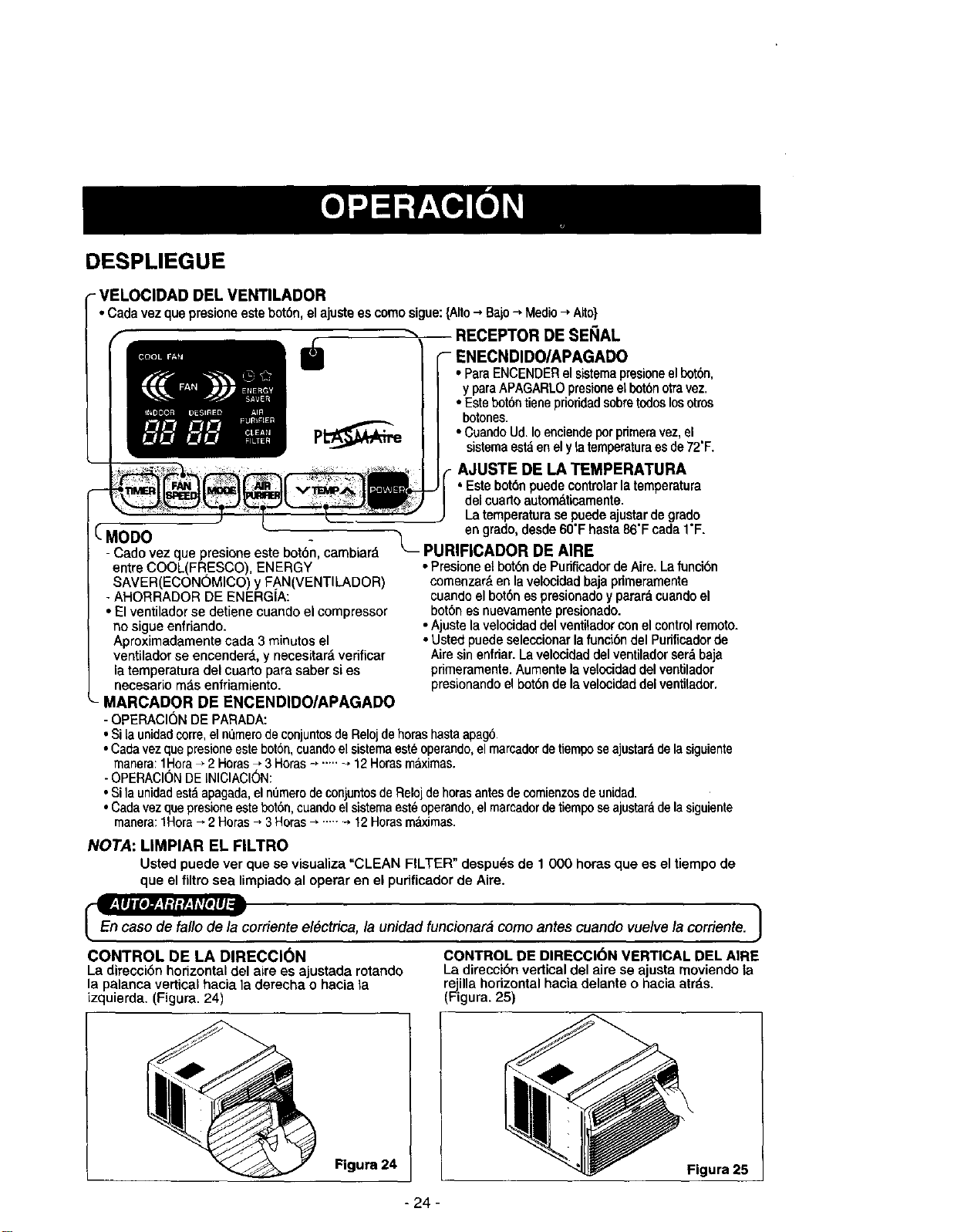
DESPLIEGUE
- VELOCIDAD DEL VENTILADOR
• Cadavezquepresioneestebot6n,elajusteescomosigue:{Alto--,Bajo-_Medio_ Alto}
(-MODO
- Cado vez que presione este bot6n, cambiard
entre COOL(FRESCO), ENERGY
SAVER(ECONOMICO) y FAN(VENTILADOR)
- AHORRADOR DE ENERGIA:
• El ventilador se detiene cuando el compressor
no sigue enfriando.
Aproximadamente cada 3 minutos el
ventilador se encender&, y necesitard verificar
la temperatura del cuarto para saber si es
necesado mds enfriamiento.
MARCADOR DE ENCENDIDO/APAGADO
- OPERACI6N DE PARADA:
RECEPTOR DE SENAL
• ParaENCENDERel sistemapresioneelbot6n,
y paraAPAGARLOpmsioneelbotbn otravez.
• Estebol6ntiene pdofidadsobre todoslosotros
botones.
• Cuando Ud. Ioenciendepor primeravez, el
sistemaest_en el y latemperaturaes de72'F.
AJUSTE DE LA TEMPERATURA
• Estebot6npuedecontrolarlatemperatura
delcuartoautomdticamente.
La temperaturase puedeajustar de grade
en grado, desde 60"F hasta86"F cada I"F.
PURIFICADOR DE AIRE
• Presione el bot6n de Purificador de Aire. Lafuncibn
comenzarb on la velocidad baja primeramente
cuando el bot6n es presionadoy parard cuando el
bot6n esnuevamente presionado.
• Ajuste la velocidad del ventltador con el control remoto.
• Usted puede seleccionar la funcibn del Purificador de
Aire sin enfriar. La velocidad del ventilador serb baja
pdmeramente. Aumente la velocidad del ventilador
presionando el bot6n de la velocidad del ventilador.
• Si la unidadcorre,el n_merode conjuntosdeRelojdehoras hastaapag6.
• Cadavezque presioneeste bot6n,cuandoel sistemaest6 operando,el marcadordoIiemposeajustarddo la siguiente
rnanera:1Hora." 2 Horas-, 3 Horas--,""" _,12 Horasm&ximas.
- OPERACIONDE INICIACI6N:
• Si la unidadestdapagada,el numerodeconjuntosde Reloj dehorasantesde comienzosde unidad.
• Cadavezque presioneeste bot6n,cuandoel sistemaest_operando,el mareadordetiempo seajustardde lasiguiente
manera:1Hora_ 2Horas _ 3Horas_ "'" -+12Horasm_ximas.
CONTROL DE LA DIRECCI(_N
La direcci6n horizontal del aire es ajustada rotando
la palanea vertical hacia la derecha o hacia la
izquierda. (Figura. 24)
NOTA: LIMPIAR EL FILTRO
Usted puede ver que se visualiza "CLEAN FILTER" despu_s de 1 000 horas que as el tiempo de
que el filtro sea limpiado al operar en el pudficador de Aire.
_corriente el6ctdca, la unidad funcionara como antes cuando vuelve la corriente. 1
CONTROL DE DIRECCl6N VERTICAL DEL AIRE
La direcei6n vertical del aire se ajusta moviendo ta
rejilla horizontal hacia delante o hacia atrds.
(Figura. 25)
Figura 24
_igura 25
- 24 -
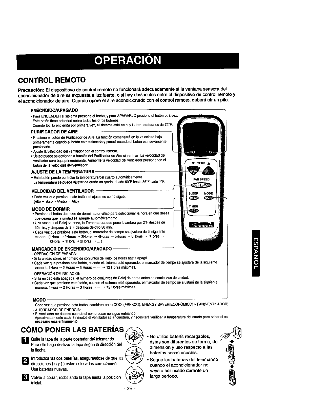
CONTROL REMOTO
Precauci6n: El dispositiovo de control remoto no funcionard adecuadamente si la ventana sensora del
acondicionador de aire es expuesta a luz fuerte, o si hay obstdculos entre el dispositivo de control remoto y
el acondicionador de aire. Cuando opere el aire acondicionado con el control remoto, deber4 oir un pito.
ENECNDIDO/APAGADO
•Para ENCENDERelsisternapresioneelbotde,y paraAPAGARLOpresioneelbot0notrevez.
Estebo_n tienepdeddadsobretodoslosotrosbotones.
CuandoUd. Ioenciendepotprimeravez, elsistemaestaen ely latemperaturees de72"F.
PURIRCADOR DE AIRE
• Presioneelbot6nde Pdeficaderde Aire,Lafunci6ncomenzar_enla velocidadbaja
primeramentecuandeel botdees presionadoy parar_cuandoel bot6nes nuevamente
presionade.
• Ajustelavelocidaddelventiladorconel controlremoto.
• Ustedpuedeseleccionarla funci6ndelPudficadorde Aimsinenfriar Lavelocideddel
ventiladorser_bajapdmeramente.Aumentelavelocideddelventiladerpresionandeel
botde de lavelccidaddelventilader.
AJUS'TE DE LA TEMPERATURA
• Este botdeposdecontrolarlatemperatura_elcuartoautom_ltcamente.
Latemderaturasepuedeaiustarde gmdoen grade,desde60"F hasta86"FcedeI"F.
VELOClDAD DEL VENTILADOR
•Cadavezquepresioneestebotbn,elajusteescomesigue:
{Alto_ Bajo_ Medio_ Alto}
MODO DE DORMIR -
• Presioneei bot0nde modede dermirautomdticoparaseleccionarlahora enque desea
quedeaeaquela unidadseapague automdticamente,
• Unavezque elRelojse pone,laTemperaturaqueponelevantar_por2"Fdesp_sde
30 min.,y despu_sde 2'F despudsdeotto30min.
•Cada vezque presioneestebotbn,elmarcaderde tiempose ajustarddela siguiente
manera:(1Hera _ 2Horas _ 3Horas _ 4Horas _ SHores _ 6Horas _ 7Horas*
OHora_lHora _2Horas _..)
MODE
MARCADOR DE ENCENDIDO/APAGADO
-OPERACI(SNDE PARADA:
• Si launidadcorre,elnOmerodeconjuntosde Relojde horashastaapag0
• Cedevez quepresioneestebotbn,cuandeelsistemaest6operando,elmarcaderdeltempo se ajustardde lasiguiente
manera:1Hera_ 2 Hems --,3 Heras_ ..-.._ 12Horasm_ximas.
- OPERACI6N DE INICIACI_N:
• Si la unidadest_ apagade,el n_merode conjuntosde Relojde horas antesde comienzosde unidad.
•Cade vezdee presioneestebot0n, cuandeel sistemaest_operando, el marcador detiemposeajustard dela siguiente
manera:1Hora _ 2 Horas_ 3 Horas _ ....._ 12Horasm_ximas.
MODO
-Cade vez quepresioneoste botde,cambiaraentreCOOL(FRESCO),ENERGYSAVER(ECON(_)MICO)y FAN(VENTILADOR)
- AHORRADORDE ENERGIA:
• El venltlador se detienecuandoel compressorno sigueenfriando.
Aproximadamentecede3 minutosel venltlador seencender&,y necesitard verificarla temperaturadelcuarto parasaber si es
necesariomasenfriamiento.
COMO PONER LAS BATER{AS
[] Quite la tape de la parte posterior del telemando, k_li'_'_J
Para ello haga deslizar la lapa seg_ln la direcciOn del
la flecha.
Introduzca las dos baterias, asegurandose de que las _ _p_'j../
I_"_ direcciones (+) y (-) esten colocadas correctament.
Use baterias nuevas. /F_
I_ Volver a cerrar, resbalando tapa posici6n
la hasta la
inicial.
- 25 -
"Ns_Utilicscenbca_e:{_s _eeCajg fb_ emSa,de
dimensibn y uso respecto alas |[_
baterias secas usuales.
• Seque las baterias del telemando
cuando el acondicionador no
vaya a ser usado durante un
largo periodo,
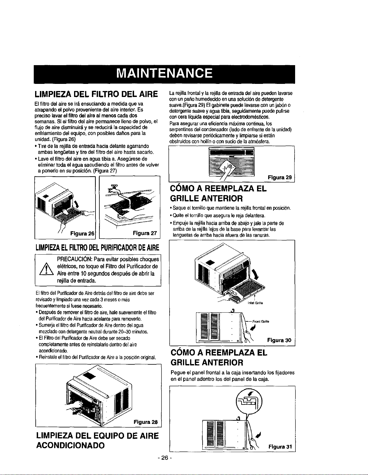
LIMPIEZA DEL FILTRO DEL AIRE
Elfiltro del aire seird ensuciandoa medidaqueva
atrapandoelpolvoprovenientedel aire interior.Es
precisolavarelfiltrodel airsal menoscada dos
samanas.Si elfiRrodal aire permanecellanode poivo,el
flujo deaire disminuirdy se reducirdracapacidadde
enfriamientodelequipo,con posiblesdaflospara la
unidad.(Figura26)
• Tirede la rojillade entradahacia delante agarrando
ambaslengOetasy tiredel firm delaire hastasacarlo.
• Laveel firm del aire en aguatibiaa. AsegL_resede
eliminartodaelagua sacudiendoel filtroantesde volver
a ponedoensu posici6n.(Figure27)
LIMPIEZAELFILTRODELPURIFICADORDEAIRE
PRECAUCION:Paraevitarposiblescheques1
//_ el_tdcos,no toqueel Filtrodel Purificadorde /
Aire entre 10segundosdespudsde abrir la J
rejilladeentrada. /
Elfiltrodel PurificadordeAiredetrasdelfiRrodealredebeser
revisadoyliropiadounavezcada3mesesornas
frecuentementesifuesenecesario.
• Despuesderemoverelfiltrodeaire,halesuavementeel filtro
delPuRficadordeAirehaciaadalantepararernoverlo.
• SuroeijaelfiltrodelPufificadordeAiredentrodalagua
mezcladocondetergenteneutraldurante20_30roinutos.
• ElFiRrodelPurificadordeAiredebesersecado
coropletamenteantesdereinstalarlodentrodelalre
acondicionado.
• ReinstaleelfiltrodelPunficadordeARea laposici6noriginal.
Figura 28
LIMPIEZA DEL EQUIPO DE AIRE
ACONDICIONADO
- 26 -
La rejillafrontaly larejillade entraciadel airepuedenlavarse
conun patiohurnedecidoen una soluei_ de detergente
suave.(Figura29)El gabinetepuedelavarsecon unjabono
detergentesuavey agua tibia,seguidamentepuedepulirse
conceratiquidaespecialparaelectrodom_sticos.
Paraasegurarunaeficienciarr_ima continua,los
serpentinesdelcondensador(ladode enfrentede la unidad)
deben revisarseperibdicamentey limpiarsesiestdn
obstruidosconhoUfnoconsueiode la atmbsfera.
Flgura 29
CC)MO A REEMPLAZA EL
GRILLE ANTERIOR
• Saqueeltornilloquemantienelarejillafrontalen posici6n.
• Quiteel tomillo queasegurale reja delantera.
• Eropujelarejillahacia arribade abajoyjale laparlede
arribadela rejillalejosdela base paralevantarlas
lenguetasde arriba haciaafuerade lasranuras.
COMO A REEMPLAZA EL
GRILLE ANTERIOR
Pegue el panel frontal a la caja insedando losfijadores
en el panel adentro losdel panel de lacaja.
Flgura 31
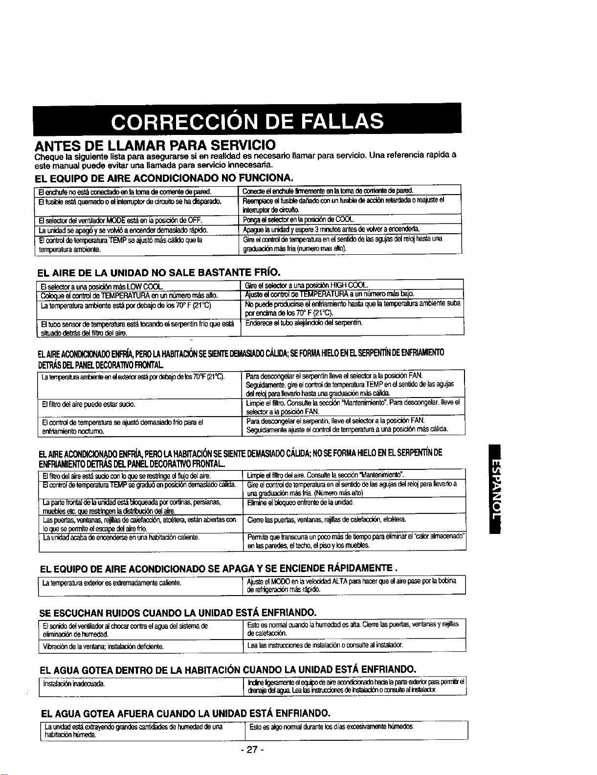
ANTES DE LLAMAR PARA SERVIClO
Cheque la siguiente lista para asegurarse si en realidad es necesario Ilamar para servicio. Una referencia rapida a
este manual puede evitar una Ilamada para servicio innecesaria.
EL EQUIPO DE AIRE ACONDIClONADO NO FUNClONA.
Elenchufenoest_conectadoenlatomadeconientedepared.
B lusibleestdquemadoo sHntemJptordecircuitosehadisparade.
Elselectordelven_derMODEest_enlapos_ deOFF.
Launidadseapagbysevolv_aencenderdemasiader_pide.
Elco*'_oldetemperaturaTEMPseajust6rodsc_idoquela
temperaturaaml_ente.
Conecteele_hufe_ enlatomademrrientedepared.
ReemptaceelEJSibledafladeconunlusi)ledeacci_xlletardadeoreajusteel
intenuptordedrcuito.
Poma_ selectoren_ posici6ndeCOOL
Apaguelaunidadyespere3minutosariesde_lveraence_
Giieelcordroldeternperaturaenelsen6dedelasagujasdelrelojbasrauna
gradeaci_rr_slria(numemmasalto).
EL AIRE DE LA UNIDAD NO SALE BASTANTE FR{O.
Elselectora unaposid(YlmdsLOWCOOL GimelselectoraunaIx_ HIGHCOOL
i ColoqueelcontroldeTEMPERATURAenunn_merom,._salto. AjusteelconkoldeTEMPERATURAa unn_mero_ ba!o.
Latemperaturaambienteestdpordebajodelos 70°F (21°C) No puedeproducirseelenlT_iento hastaquela temperaturaamb_entesuba
pote_cimadelos70°F(21°C).
Eltubosensordetemperaturaestdtecandoelserpentinfn'oqueestd Endereceeltuboalejdndolodel serpent_n.
siluadodetr,_sdelfillrodelaim.
Elfiltrodelairepuedeestarsuc_o.
Elcontroldetemperaturaseajustbdemasiadofn'oparaet
enffiamientonoctumo.
ELAIREACONDICIONADO_ PEROLAHABiTACIONSESIENTEDEMASIADOCAUDA;SEFORMAHIELOENE SERPENliNDEENFRIAMIENTO
DET_SDELPANEDECORA'I1VOFRONTAL
LatempeaturaaTid_ end _ es_ potdd_ajodeles70°F(21°C). Paradesconge_relserpentinIleveeEselectorala posiddeFAN.
Seguidamente,gireel(:onlmldetemperaturaTEMPenelsen_dedelasagujas
delrek_paraIlevadehastauna@raduaci6nrndsc_de.
Umpieelfiltro.C(x_ultelasecci_ "Mantenimie_to'.Parddescongelar,Ileveel
selectorala posici_FAN.
Paradescongela_elserpentin,Ileveelselectora laposicionFAN.
Seguidamenteajusteelce_roldeternperaturaaunaposiddemasc_ida.
E AIREACONDICIONADOENFR{A,PEROLAHABITACIONSESIENTEDEMASIADOC._UDANOSEFORMAHIELOENELSERPEN"il'NDE
ENFRIAMIENT0DETRASDELPANELDECORATIVOFRONTAL.
Ell_odela_reest_sucioconb q_Jeserestringeel11ujodelaire.
ElcontroldetemperahlraTEMPsegradu6enposici6ndemasiadoctdida.
Lapartefronlalde[aL_ad est_bloqueadapo_coflJnas,personas,
muebleset_queres_ngenla _ delaim.
Laspuertas,ventanas,rsjillasdecalefaccibn,etcetera,est_nabiertascon
Ioopeseperrniteelescapedelaireffio.
Launidadacabadeencende_seenunahabitacidecaliente.
lJmp_eelfilbode_aim,Consultelaseccide'Mante_imiento'.
Gireelcontroldetemperaturaenelsentidedelasagu_sde{re_paraIlevarioa
una@mdeaci_r_slffa.(Numero_ alto)
Elimireelbloqueoenfrentedelaunided.
Cietrelaspuertas,_nta_as,_i,as dec_Jefacci@_,etc_tera_
Permitaquettanscurraunpocor_ de_empoparaeliminarel=caloralmacenado"
enlasparedes,eltecho,elp_soylosmuebles.
EL EQUIPO DE AIRE ACONDICIONADO SE APAGA Y SE ENCIENDE R/_.PIDAMENTE.
I Latemperaturaexted°resex_rnadementecaliente' AjusteeiMOO0enla"_l°ddadALTAParahaterqueelairePaSeP°r_abdeinaIderefrigeraddem_sr_de.
SE ESCUCHAN RUIDOS CUANDO LA UNIDAD ESTA ENFRIANDO.
I Estoes normalcuandolahumedadesalia.Cierrelaspue_s, ventanasy _illas
Elso_idedelver_ado(a]chocarcontmelaguadelsistemade L decalefacck_n"
eliminaddedehumedad.
V'_rac_delaventana;instabci#ndelete. _ Lealasinstruccionesdeinslalacideoconsulteali_sta_ader.
ELAGUA GOTEA DENTRO DE LA HABITACI(_NCUANDO LA UNLOADEST._,ENFRIANDO.
I Inswla_inade_ I i_e i_r_te eleq_pode_ _(_de hac_alaPe,lee,"_e_ParaPen_e_
_lenapdela_.__Lealasins_ucdonesdei'_.a_adb_oconsolea_inslalade_,
EL AGUA GOTEA AFUERA CUANDO LA UNIDAD ESTA ENFRIANDO,
I Launidadest_ex1_ayendOgrandescan_ dehumededdeunahab_aci__meda. I "al d'as
- 27 -

o28 _

i 29_

- 30 -
Master Protection Agreements
Congratulations on making a smart purchase.
Your new Kenmore° product is desJgned and
manufactured for years of dependable operation.
But like all products, it may require preventive
maintenance or repair from time to time.
That's when having a Master Protection Agreement
can save you money and aggravation.
Purchase a Maser Protection Agreement now and
protect yourself from unexpected hassle and
expense.
The Master Protection Agreement also helps extend
the lifeof your new product. Here's what's included
in the Agreement:
[] Expert service by our 12,000 professional
repair specialists
[] Unlimited service and no charge for parts and
labor on all covered repairs
[] "No-lemon" guarantee - replacement of your
covered product iffour or more product failures
occur within twelve months
]Product replacement if your covered product
can't be fixed
[] Annual Preventive Maintenance Check at your
request - no extra charge
[] Fast help by phone - phone support from a
Sears technician on products requiring in-home
repair, plus convenient repair scheduling
[] Power surge protection against electdcal
damage due to power fluctuations
[] Rental reimbursement ifrepair of your covered
product takes longer than promised
Once you purchase the Agreement, a simple phone
call is all that ittakes for you to schedule service.
You can call anytime day or night, or schedule a
service appointment online.
Sears has over 12,000 professional repair
specialists, who have access to over 4.5 million
quality parts and accessories. That's the kind of
professionalism you can count on to help prolong
the lifeof your new purchase for years to come.
Purchase your Master Protection Agreement today!
Some limitations and exclusions apply.
For prices and additional information call
1-800-827-6655.
Sears Installation Service
For Sears professional installation of home
appliances, garage door openers, water
heaters, and other major home items, in the
U.S.A. call 1-800--4-MY-HOME ®
Acuerdos de Protecci6n Especializada
iEnhorabuenat Ha realizadouna comprainteligente.
Su nuevoaparato Kenmors_ estddiseSadoy fabricado
paraofrecedeaSosde buenfuncionamiento.
Sinembargo, al igualque todoslos productos,puede
precisar un mantenimiento preventiveoinclusoalguna
reparacibnde vez encuando.En esasocasiones,un
Master ProtectionAgreementpuedeayudarlea ahorrar
dineroe fnconvenientes.
Adquiera unMaser Protection Agreement ahora, y
protejase a s[ mismo de molestias y gastosinesperados.
El Master ProtectionAgreement le ayudard tambien a
prolonger la vida de su nuevo aparato. Los siguientes
servicios est&n incluidos:
[] Servicio experto por parte de cualqulera de
nuestros 12.000 t_cnicosprofesionales especialistas
de Sears.
[] Prestaci6n de servicios sin limitaclones y sin
cargarle las piezas o la manode obra en todas las
reparacionescubiertaspotel acuerdo.
[] Garantia seria desustituci6n de las piezss del
productocubierto por el acuerdo,sicuatroo mas
piezasse mostrasen defectuosasen un periodode
docemeses.
[] Sustituci6n del producto por otro nuevo, si el
defectuoso nopudieserepararse,
[] Control de mantenimiento anual preventivo,
siempreque Iodeseey singastoadieional alguno.
[] Asistencia telef6nica inmediate de ontecnico
especiaiista en productos quehen de ser reparadosa
domicilio,adem:_sde una programaci6nadecuada de
la reparaci6n.
[] Pretecci6n eontra subidas de tension que
provoquen daSoseldctricos debidos alas
fluctuaciones en el suministro.
[] Reintegro del alquiler si lareparacion del producto
Ilevama.stiempo del promtetido
Una vezque haya adquiddo el Agreement, no necesitar_
mds que una simple Ilamada pare soiicitar el servicio de
su aparato. Ademds, podr_ hacerlo en cualquier momento
del dia o de la noche, o solioitarunacitapara prestacibn
de serviciosonline.
Sears cuentacon mdsde 12.000t_cnicosprofesionales
especialistas en repamciones, con acceso a m_s de 4,5
millones de piezas de sustituci6n y acoesorios de calidad.
Este sera el tipo de profesionalidad y servicio con el que
podrd contar pare prolongar la vida de su nuevo producto
por muchos ahos. iAdquiera hey mismo su Master
Protection Agreement!
Se aplicardn algunas limitaciones y
restricciones.
Si desea hacer alguna consulta sobre los
precios u otra informaci6n adicional, le rogamos
Ilame al teldfono 1-800-827-6655.
Servicios de Instalaci6n Sears
Pare solicitar servicios de instalaci6n profesionales
de Sears de electrodom_sticos, mandos de aperture
de puertas de garajes, calentadores de agua y otres
aparatos en los Estados Unidos, puede Ilamar a
1-800-4-MY-HOME °
-31 -

Your Home
For repair - in your home-of all major brand appliances,
lawn and garden equipment, or heating and cooling systems,
no matter who made it, no matter who sold it!
For the replacement parts, accessories and
owner's manuals that you need to do-it-yourself.
For Sears professional installation of home appliances
and items like garage door openers and water heaters.
1-800-4-MY-HOME ® (1-800-469-4663)
Call anytime, day or night (U.S.A. and Canada)
www.sears.com www.sears.ca
Our Home
For repair of carry-in items like vacuums, lawn equipment,
and electronics, call or go on-line for the location of your nearest
Sears Parts & Repair Center.
1-800-488-1222
Call anytime, day or night (U.S.A. only)
www.sears.com
To purchase a protection agreement(U.S.A.)
or maintenance agreement(Canada) on a product serviced by Sears:
1-800-827-6655 (U.S.A.) 1-800-361-6665 (Canada)
Para pedir servicio de reparacibn
a domiclho, y para ordenar piezas:
1-888-SU-HOGAR s_
(1-888-784-6427)
Au Canada pour service en fran(_ais:
1-800-LE-FOYER _c
(1-800-533-6937)
www.sears.ca
® Registered Trademark / TMTrademark / suService Mark of Sears, ROebuck and Co
® Marca Reglstrada / TMMarca de F_bnca / s.uMarca de Servic,o de Sears, Roebuck and Co
_c Marque de commerce ! MDMarque (_posL=e de Sears, Roebuck and Co ® Seats, Roebuck and Co
Part No 3828A20307J