Instruction
Sheet
for
Evaporator
Drain
Tray
Assembly
Installation
cacor
Refrigerator
Models:
EF42BDCB, EF48BDCB, EF42BNDB,
EF48BNDB,
IF42BDCB,
IF48BDCB,
IF42BNDB,
IF48BNDB
Kit
Part
Numbers:
W10199913
(42-Inch
models),
W10199915
(48-Inch
models)
AWARNING
Electrical
Shock
Hazard
Disconnect
power
before
servicing.
Replace
all
parts
and
panels
before
operating.
Failure
to
do
so
can
result
in
death
or
electrical
shock.
Kit
Contains:
1
Clip
6
Sealer-Gum
(Butyl)
1
Clamp
1
Evaporator
Drain
Tray
Assembly
1
Drain
Tube
1.
Instruction
Sheet
Standard
product
manufacturing
warranty
applies.
IMPORTANT:
Evaporator
Drain
Tray
Freeze
Up
Issue
in
2003
thru
2007
production
—
Creates
internal
water
leak
from
ceiling
of
freezer
causing
water
and
ice
to
accumulate
on
the
ceiling,
door
and
seals
of
freezer.
Can
also
cause
a
no
cool
situation,
a
noise
issue
when
ice
forms
blocking
evaporator
motor
and
blade,
or
damper
diffuser
failure.
NOTE:
All
steps
must
be
followed
for
a
proper
repair.
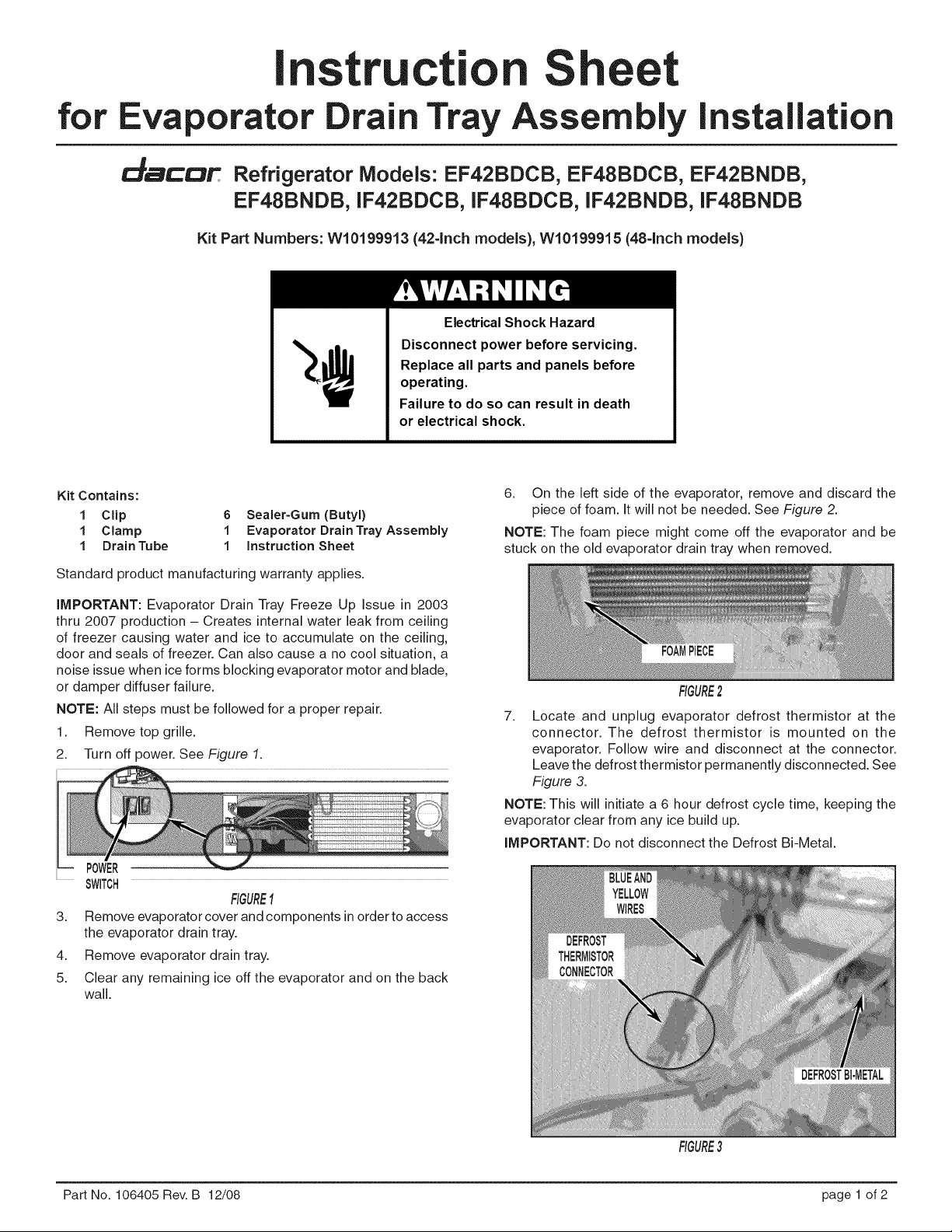
1.
Remove
top
grille.
2.
‘Turn
off
power.
See
Figure
7.
POWER
SWITCH
FIGURE
1
3.
Remove
evaporator
cover and
components
in
order
to
access
the
evaporator
drain
tray.
Remove
evaporator
drain
tray.
5.
Clear
any
remaining
ice
off
the
evaporator
and
on
the
back
wall.
6.
On
the
left
side
of
the
evaporator,
remove
and
discard
the
piece
of
foam.
It
will
not
be
needed.
See
Figure
2.
NOTE:
The
foam
piece
might
come
off
the
evaporator
and
be
stuck
on
the
old
evaporator
drain
tray
when
removed.
FOAM
PIECE
FIGURE
2
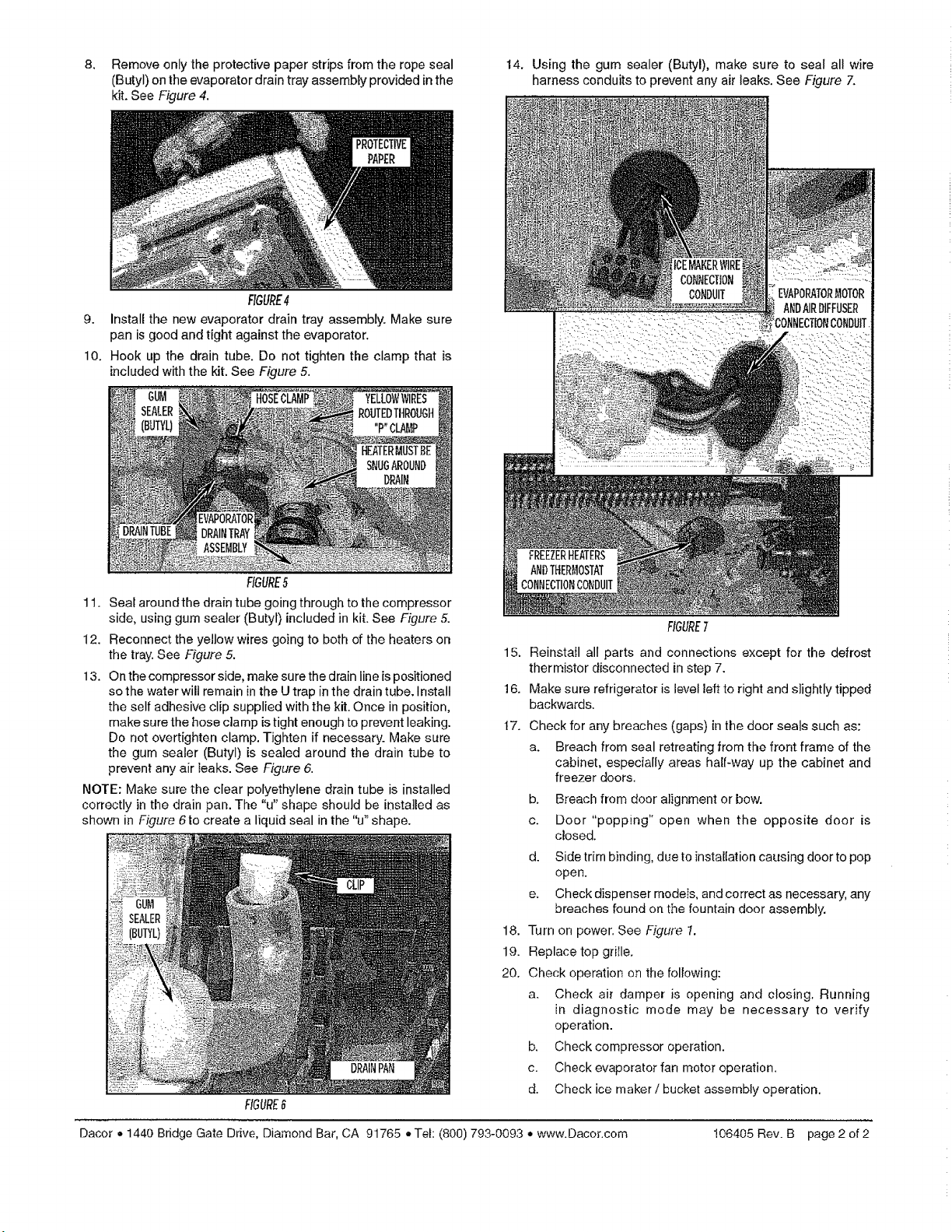
7.
Locate
and
unplug
evaporator
defrost
thermistor
at
the
connector.
The
defrost
thermistor
is
mounted
on
the
evaporator.
Follow
wire
and
disconnect
at
the
connector.
Leave
the
defrost
thermistor
permanently
disconnected.
See
Figure
3.
NOTE:
This
will
initiate
a
6
hour
defrost
cycle
time,
keeping
the
evaporator
clear
from
any
ice
build
up.
IMPORTANT:
Do
not
disconnect
the
Defrost
Bi-Metal.
DEFROST
THERMISTOR
CONNECTOR
FIGURE
3
Part
No.
106405
Rev.B
12/08
page
1
of
2
8.
Remove
only
the
protective
paper
strips
from
the
rope
seal
(Buty!)
on
the
evaporator
drain
tray
assembly
provided
in
the
kit.
See
Figure
4.
FIGURE
4
9.
Install
the
new
evaporator
drain
tray
assembly.
Make
sure
pan
is
good
and
tight
against
the
evaporator.
10.
Hook
up
the
drain
tube.
Do
not
tighten
the
clamp
that
is
included
with
the
kit.
See
Figure
5.
ee
CUM
ae
HOSE
CLAMP
a
ATee
LR
Ra
A
“YELLOW
WIRES
ROUTED
THROUGH
"P"
CLAMP
|
HEATER MUST
BE
SNUG
AROUND
DRAIN
EVAPORATOR
DRAIN
TRAY
ASSEMBLY
FIGURE
§
11.
Seal
around
the
drain
tube
going
through
to
the
compressor
side,
using
gum
sealer
(Butyl
included
in
kit.
See
Figure
5.
12.
Reconnect
the
yellow
wires
going
to
both
of
the
heaters
on
the
tray.
See
Figure
5.
13.
Onthe
compressor
side,
make
sure
the
drain
line
is
positioned
so
the
water
will
remain
in
the
U
trap
in
the
drain
tube.
Install
the
self
adhesive
clip
supplied
with
the
kit.
Once
in
position,
make
sure
the
hose
clamp
is
tight
enough
to
prevert
leaking.
Do
not
overtighten
clamp.
Tighten
if
necessary.
Make
sure
the
gum
sealer
(Butyl)
is
sealed
around
the
drain
tube
to
prevent
any
air
leaks.
See
Figure
6.
NOTE:
Make
sure
the
clear
polyethylene
drain
tube
is
installed
correctly
in
the
drain
pan.
The
“u”
shape
should
be
installed
as
shown
in
Figure
6
to
create
a
liquid
seal
in
the
“u”
shape.
FIGURE
6
14,
Using
the
gum
sealer
(Butyl),
make
sure
to
seal
all
wire
harness
conduits
to
prevent
any
air
leaks.
See
Figure
7.
CONNECTION
Gas
won
=
CONDUIT
2
EVAPORATOR
MOTOR
oe
ae!
AND
AIR
DIFFUSER
CONNECTION
CONDUIT
FREEZER HEATERS
AND
THERMOSTAT
CONNECTION
CONDUIT
FIGURE
7
15.
Reinstall
all
parts
and
connections
except
for
the
defrost
ihermistor
disconnected
in
step
7.
16.
Make
sure
refrigerator
is
ievel
left to
right
and
slightly
tipped
backwards.
17.
Check
for
any
breaches
(gaps)
in
the
door
seals
such
as:
a.
Breach
from
seal
retreating
from
the
front
frame
of
the
cabinet,
especially areas
half-way
up
the
cabinet
and
freezer
doors.
b.
Breach
from
door
alignment
or
bow.
c.
Door
“popping”
open
when
the
opposite
door
is
closed.
d.
Side
trim
binding,
due
to
installation
causing
door
to
pop
open.
e.
Check
dispenser
models,
and
correct
as
necessary,
any
breaches
found
on
the
fountain
door
assembly.
18.
Turn
on
power.
See
Figure
7.
19.
Replace
top
grille.
20.
Check
operation
on
the
following:
a.
CGheck
air
damper
is
opening
and
closing.
Running
in
diagnostic
mode
may
be
necessary
to
verify
operation.
b.
Check
compressor
operation.
Check
evaporator
fan
motor
operation.
Check
ice
maker
/
bucket
assembly
operation.
Dacor
«
1440
Bridge
Gate
Drive,
Diamond
Bar,
CA
91765
e
Tel:
(800)
793-0093
«
www.Dacor.com
106405
Rev.B
page
2of2

