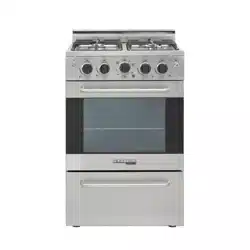
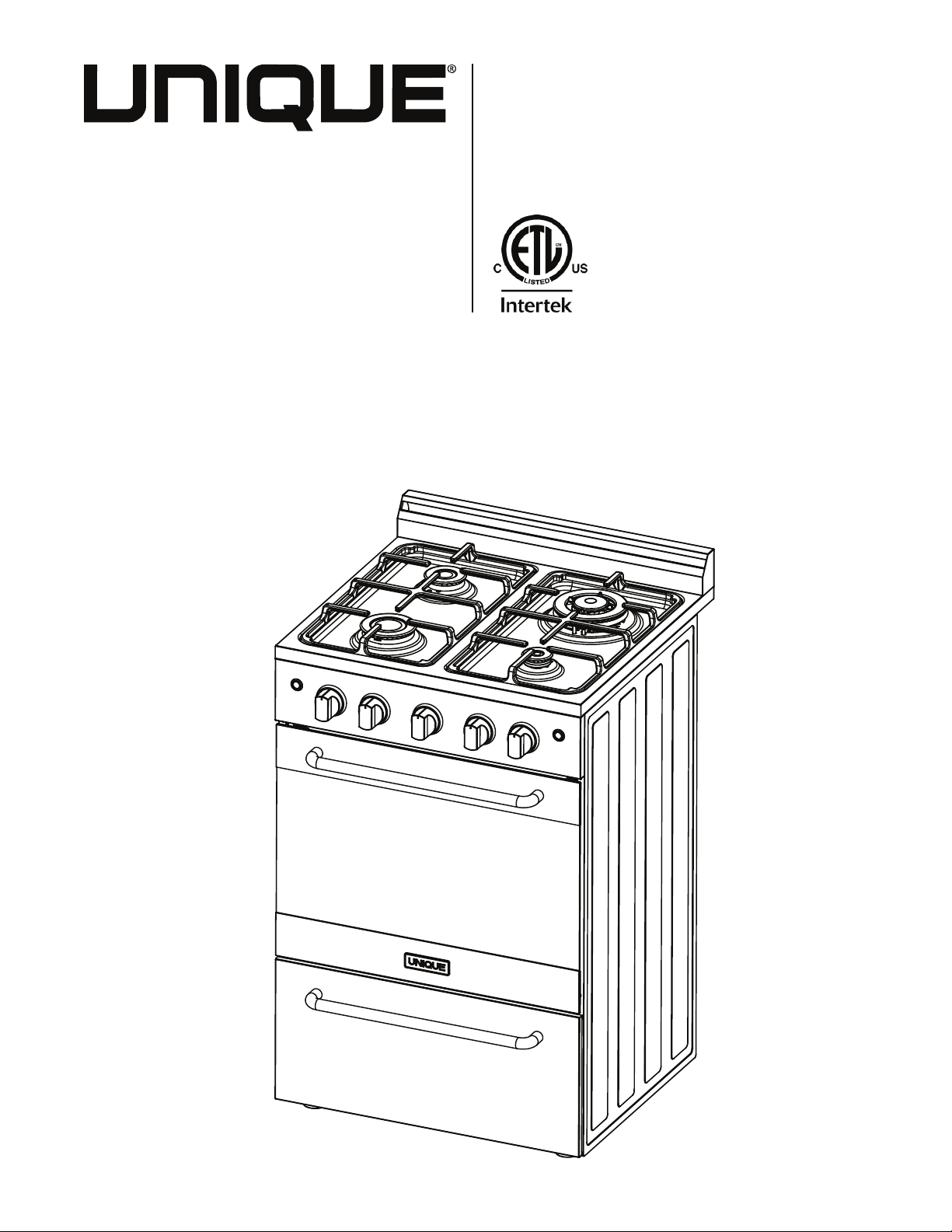
UGP-24V PC1 S/S
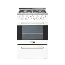
UGP-24V PC1 W
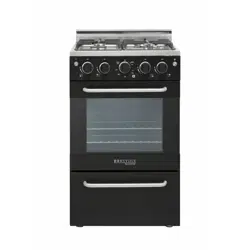
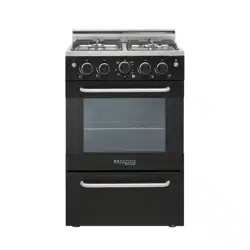
UGP-24V PC1 B
24” (60.9 cm)
PRESTIGE GAS RANGE
(NG & LPG convertible)
INSTALLATION
AND OWNER’S MANUAL
SERIAL NUMBER:
JUNE17V1
READ AND SAVE THESE INSTRUCTIONS
File Number:
4009900
SEP20V3
UNIQUE 24” PRESTIGE MODEL
GAS RANGE - NG & LPG CONVERTIBLE
READ AND SAVE THESE INSTRUCTIONS
Have the dealer where you purchase your new range install it or have him recommend
a qualied installer. Installation must conform with local codes. In the absence of local
codes, the installation must conform with the National Fuel Gas Code, ANSI Z223. 1-Lat-
est Edition in the U.S.A. or the CAN/CGA B149.1 or .2 Installation Codes in Canada.
Installation & Owner’s Manual
This manual contains information for:
Important Safeguards
Installation
Use and Care
Certain ranges come equipped with special features. Determine from a study of
your range which of the instructions given in this booklet pertain to your range.
This booklet gives valuable instructions covering the installation, adjustment
and use of your range.
How to Obtain Service and/or Parts
When your range does not operate in accordance with the instructions in the manual,
you should contact the dealer in your immediate vicinity for service. Or, the purchaser
may contact the service organization noted on the warranty.
Important
TO THE OWNER OF THE RANGE: Retain this owner’s manual for future reference.
TO THE INSTALLER: Leave this owner’s manual with the range.
Read and Save These Instructions
2245 Wyecroft Road #5
Oakville, Ontario, Canada L6L 5L7
Ph: 905-827-6154 Toll Free: 1-877-427-2266 Fax: 905-827-2027
www.UniqueOffGrid.com
MANUFACTURED & CERTIFIED BY
Unique Gas Products Ltd
X2

4
05 Important safety instructions
14 Energy saving ideas
15 Installation instructions
16 How to install the backsplash
17 Gas connections
20 Wall clearances
22 Gas range conversion
27 Adjustingthetopburnerandovename
30 Operation of range
36 Alignments and adjustments
37 Cleaning the range
39 Care and maintenance
44 Troubleshooting
46 Wiring diagram
47 Contact us
47 Warranty
48 Parts diagram
49 Parts list
52 Appliance information
53 Notes
UNIQUE GAS RANGE
Table of Contents
5
BEFORE USING YOUR GAS RANGE
WARNING
HAVE THIS RANGE INSTALLED BY A QUALIFIED INSTALLER.
Improper installation, adjustment, alteration, services, or maintenance can cause injury or prop-
ertydamage.Consultaqualiedinstaller,serviceagency,orthegassupplier.
BEFORE USING YOUR GAS RANGE:
•Removetheexteriorandinteriorpacking.
•Removetheprotectivelmonsteelandaluminumparts.
•Checktobesureyouhaveallofthepartslistedbelow.
• 1 backsplash
• LP gas conversion packet (injectors for LP gas, 6pcs)
• 2 anti-tip brackets
• 2 pan supports
• 2 oven racks
• 4 caps and bases in the burner assembly
• 1 broiler grid
• 1 broiler tray
• 1 regulator (pre-installed)
• 5 screws for backsplash
• 1 instruction/installation manual
•Cleantheinteriorsurfacewithlukewarmwaterusingasoftcloth
•Havetheinstallershowyouthelocationoftherange’sgasshut-offvalveandhowtoshutit
off if necessary.
•Haveyourrangeinstalledandproperlygroundedbyaqualiedinstallerinaccordancewith
the installation instructions.
•Donotattempttorepairorreplaceanypartofyourrangeunlessitisspecicallyrecommend-
ed in this manual.
•Besureyourrangeiscorrectlyadjustedbyaqualiedservicetechnicianorinstallerforthe
type of gas (natural or LP) that is being used.
•Donotremovepermanentlyafxedlabels,warnings,orplatesfromtheunit.Thismayvoid
the warranty.
•Theinstallershouldleavetheseinstructionswiththeconsumerwhoshouldretainforlocal
inspector’s use and for future reference.
•Pleaseobservealllocalandnationalcodesandordinances.

6
Welcome & Congratulations
Congratulations on your purchase of a UNIQUE range! We are very proud of our product – and
are completely committed to providing you with the best service possible. Your satisfaction is
our #1 priority. Please read this manual very carefully. It contains valuable information on how to
properly maintain your new Unique gas range.
We know you will enjoy your new range and Thank You for choosing one of our Unique Gas
Products! We hope you will consider us for future purchases.
IMPORTANT PRECAUTIONS AND RECOMMENDATIONS
This appliance is designed and manufactured solely for the cooking of domestic (household)
food and is not suitable for any non-domestic application and therefore CANNOT be used in a
commercial environment.
The appliance guarantee will be void if the appliance is used within a non-domestic environment
i.e. a semi commercial, commercial or communal environment..
PLEASE READ AND SAVE THESE INSTRUCTIONS
Thismanualprovidesspecicoperationinstructionsforyourmodel.Useyourrangeonlyas
instructed in this manual. These instructions are not meant to cover every possible condition and
situation that may occur. Common sense and caution must be practiced when installing, operat-
ing and maintaining the appliance
Record in the space provided below the Model No. and Serial No. of this appliance.
These numbers are found on the serial plate located at the back of the range.
Model No. ________________________ Type Number _______________________
Serial No. ________________________ Purchase Date________________________
Record these numbers for future use.
IMPORTANT:
Keep a copy of your bill of sale. The date on the bill establishes the warranty
period should service be required. If service is performed, it is in your best interest to obtain and
keep all receipts.
PLEASE DO THIS NOW!
The PRODUCT REGISTRATION CARD should be lled in completely, signed and
returned. This information will register your product and help us to serve you quickly in
the future if necessary.
7
READ ALL IMPORTANT SAFEGUARDS AND
ALL INSTRUCTIONS BEFORE USING THE APPLIANCE.
IF YOU SMELL GAS:
•Openwindows
•Don’ttouchelectricalswitches
•Extinguishanyopename
•Immediatelycallyourgassupplier
FOR YOUR SAFETY:
•Keepapplianceareaclearandfreefromcombustiblematerialsgasolineandotherammable
vapors and liquids.
WARNINGS
Destroythecartonandplasticbagsaftertherangeisunpacked.Childrenshouldnotusepack-
aging material for play. Cartons covered with rugs, bedspreads, or plastic sheets can become
airtight chambers. Remove all staples from the carton. Staples can cause severe cuts and
destroynishesiftheycomeincontactwithotherappliancesorfurniture.
Be safety conscious. The preparation of food in an oven requires temperatures that could
cause severe burns. Before using this new appliance, carefully read and follow all instructions.
TheCaliforniaSafeDrinkingWaterandToxicEnforcementActof1986(Proposition65)requires
the Governor of California to publish a list of substances known to the State of California to
cause cancer or reproductive harm. In addition, businesses must warn customers of potential
exposure to such substances.
Users of this appliance are hereby warned that the burning of gas can result in low-level expo-
sure to some of the listed substances, including formaldehyde, benzene, soot and carbon mon-
oxide. This is caused primarily from the incomplete combustion of natural gas or LP fuel.
Properly adjusted burners will minimize incomplete combustion. Exposure to these substances
can also be minimized by properly venting the burners by opening a window or using a ventilat-
ing hood or fan.
WARNING

8
Notice: Never keep pet birds in the kitchen. Birds have a very sensitive respi-
ratory system. Fumes released from cooking oil, fat, margarine or overheat-
ed non-stick cookware may be harmful or fatal to birds.
PROPER INSTALLATION: Besureaqualiedtechnicianinaccordancewiththe
National Fuel Gas Code ANSI Z223.1/NFPA54 properly installs your appliance.
Install only per installation instructions provided in the literature package for this
range. Be sure leveling legs are in place at the bottom corners of the range. If nec-
essary, raise or lower the leveling legs at the base of the range by turning clock-
wise or counter clockwise to insure a level range.
Askyourdealertorecommendaqualiedtechnicianandanauthorizedrepairser-
vice. Have the technician familiarize you with the locations of the manual gas shut
off valve and gas meter in the event it is necessary to shut off gas supply to the
unit during an emergency.
The following situations may cause serious bodily harm, death or property
damage.
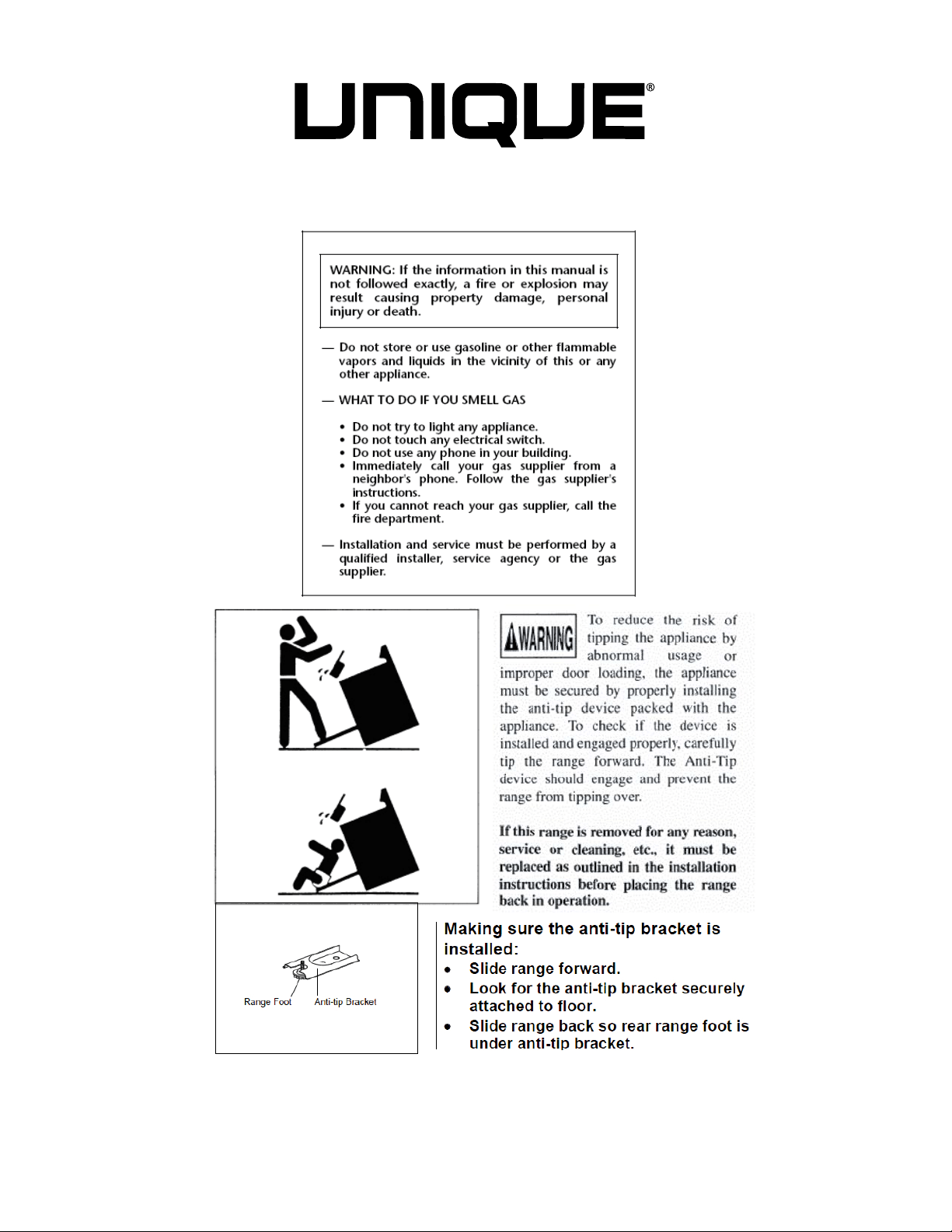
TO REDUCE THE RISK OF TIPPING OF THE RANGE, THE RANGE MUST
BE SECURED BY A PROPERLY INSTALLED ANTI-TIP BRACKET PROVIDED
WITH THE RANGE. TO CHECK IF THE DEVICE IS INSTALLED AND ENGAGED
PROPERLY, CAREFULLY TIP THE RANGE FORWARD. THE ANTI-TIP DEVICE
SHOULD ENGAGE AND PREVENT THE RANGE FROM TIPPING OVER. RE-
FER TO THE INSTALLATION INSTRUCTIONS PACKAGED WITH THE ANTI-TIP
BRACKET FOR PROPER ANTI-TIP BRACKET INSTALLATION.
• Never leave children alone or unattended in the area where an appliance is
in use. They should never be allowed to sit or stand on any part of the appliance.
Never leave the oven door open when the range is unattended.
• Do not store items of interest to children in the cabinets above a range or
on the backguard of a range. Children climbing on the range to reach the items
could be seriously injured.
Do not allow children to climb or play around the range. The weight of a child
on an open oven door may cause the range to tip, resulting in serious burns or
other injury.
IMPORTANT: Observeallgoverningcodesandordinances.Donotobstructowof
combustion and ventilation air.
9
USER SERVICING: Donotrepairorreplaceanypartoftheapplianceunless
specicallyrecommendedinthisowner’sguide.Onlyaqualiedtechnician
should do all other servicing. This will reduce the risk of personal injury and dam-
age to the range.
Storage in or on appliance: Flammable materials should not be stored in an
oven, near surface burners or in the broiler section. This includes paper, plastic
andclothitems,suchascookbooks,plasticwareandtowels,aswellasammable
liquids.Donotusetheovenforstorage.Donotstoreexplosives,suchasaerosol
cans, on or near the range.
Remove the oven door from any unused range if it is to be stored or discarded.
Stepping, leaning or sitting on the doors or broiler section of this range can
result in serious injuries and cause damage to the range.
The following situations could cause bodily injury or
property damage.
DO NOT TOUCH SURFACE BURNERS, AREAS NEAR THESE BURNERS,
OVEN BURNERS OR INTERIOR SURFACES OF THE OVEN. Both surface burn-
ersandovenburnersmaybehoteventhoughtheameisnotvisible.Areasnear
surfaceburnersmaybecomehotenoughtocauseburns.Duringandafteruse,do
nottouch,orletclothingorotherammablematerialstouchtheseareasuntilthey
havehadsufcienttimetocool.Amongtheseareasaretherange,surfacesfacing
the range, the oven vent openings and surfaces near these openings, oven door
and windows.
NEVER use this appliance as a space heater to heat or warm the room.
Doingsomayresultincarbonmonoxidepoisoningandoverheatingofthe
oven.
Wear proper apparel. Loosettingorhanginggarmentsshouldneverbeworn
whileusingtheappliance.Donotletclothingorotherammablematerialscontact
surfaceburnersorinteriorsurfacesoftheovenuntiltheyhavehadsufcienttime
to cool.
Never modify or alter the construction of the range. Donotremoveleveling
legs, panels, wire covers, anti-tip brackets or any other permanent part of the prod-
uct.
When heating fat or grease, watch it closely. Fatorgreasemaycatchreifal-
lowed to become too hot.

10
Do not use water or our on grease res. Smothertherewithapanlid,baking
soda or use a dry chemical or foam-type extinguisher.
Operation of the Surface Burners. Whentheburnersareoperatedfortherst
time, a small amount of smoke may be generated due to tape residue or manufac-
turing lubrication, this is not dangerous.Operatetheburnersforaboutvemin-
utes to rid the burners of this material before cooking.
Use only dry potholders. Wet or damp potholders on hot surfaces could result in
burnsfromsteam.Donotletthepotholdertouchhotheatingareas.Donotusea
towel or other bulky cloth instead of a potholder.
Use proper ame size. Adjustamesizesoitdoesnotextendbeyondtheedge
of the cookware. The use of undersized cookware will expose a portion of the
burnerameandmayresultinsevereburnsordirectcontactandignitionofcloth-
ing.Also,properrelationshipofcookwaretoburnerwillimproveefciency.
NEVER cover any slots, holes or passages in the oven bottom or cover
an entire rack with materials such as aluminum foil. Doingsoblocksair
owthroughtheovenandmaycausecarbonmonoxidepoisoning.Aluminumfoil
liningsmayalsotrapheat,causingarehazard.Refertothecleaningsectionof
this manual for more information on the use of aluminum foil.
Placement of oven racks: Always place an oven rack in the desired location
while the oven is cool. If a rack must be moved when the oven is hot, use pothold-
ersandgrasptherackwithbothhandstoreposition.Donotletpotholderscontact
hot oven walls. Remove all cookware from the rack before moving.
Do not heat unopened food containers. Build-up of pressure may cause the
container to burst and result in injury.
Keep the oven vent duct unobstructed. The oven vent is located along the bot-
tom of the back guard. Touching the surfaces in the vent area when the oven is
being operated may cause severe burns. Also, do not place plastic or heat-sensi-
tive items on or near the oven vents. These items could melt or ignite. The range
requiresfreshairforproperburnercombustion.Donotblocktheowofairaround
the base or beneath the lower front panel of the range.
Use care when opening oven door: Stand to the side of the oven when open-
ing the oven door. Slowly open the door to allow hot air or steam to escape
before removing or replacing food.
Know which knob controls each burner. Place a pan of food on the burner be-
fore turning it on, and turn the burner off before removing the pan. Always turn to
thefullpositionwhenignitingtopburners.Thenadjusttheamesizesoitdoesnot
extend beyond the edge of the cookware.

11
Cookware handles should be turned inward and not extend over adjacent
surface burners. Toreducetheriskofburns,ignitionofammablematerials,and
spillage due to unintentional contact with the cookware, the handle of a cookware
should be positioned so that it is turned inward, and does not extend over adjacent
surface burners.
Never leave the surface burners unattended. Boilovers may cause smoking,
greasyspill-oversmaycatchreorapanwhichhasboileddrymaymelt.
Do not place hands between the spring tension hinge and the oven door
frame when you are removing the oven door. Youcouldpinchyourngers.
Do not use the broiler pan without its insert. The broiler pan and its insert allow
dripping fat or grease to drain and be kept away from the high heat of the broiler.
Donotcovertheinsertwithfoil.Exposedfatorgreasecouldignite.
Allow parts to cool to room temperature before touching or removing them
from the range. Whenasurfaceburnerisrstturnedoff,theburnerandgrateare
hot enough to cause burns.
Clean the range regularly to keep all parts free of fat or grease, which could
catch re. Pay particular attention to the area underneath each surface burner.
Exhaustfanventilatinghoodsandgreaseltersshouldbeclean.Donotallowfat
orgreasetoaccumulate.Greasydepositsinthefancouldcatchre.Refertothe
hood manufacturer’s instructions for cleaning.
Do not use a “cyclonic” range hood with this product. Some range hoods cir-
culate air by blowing downward toward the range top then drawing the air back up
into the hood. This creates a “cyclonic” air wash that is designed for electric ranges
only. A “cyclonic” hood may cause the burners of a gas range to operate improp-
erly.
Glazed cookware: Only certain types of glass, glass/ceramic, ceramic, earthen-
ware, or other glazed cookware are suitable for rangetop service without breaking,
due to the sudden change in temperature. Check the manufacturer’s recommenda-
tions for rangetop use.
Do not place plastic salt and pepper shakers, spoon holders or plastic wrap-
pings on top of the range. These items could melt or ignite. Potholders, towels or
woodenspoonscouldcatchreifplacedtooclosetotheame.
Do not use a wok equipped with a metal ring that extends beyond the burner.
Because this ring traps heat, the burner and grate could be damaged. Also, the
burner may not work properly, creating a carbon monoxide level above current
health standards.
Do not clean the oven door gasket. The door gasket is essential for a good seal.
Care should be taken not to rub, damage or move the gasket.
12
Flexible Connectors: If the gas range/oven is connected to a gas supply with a
metalexibleconnector,movetherange/ovenwithCAUTIONforserviceorcleaning.
Flexible connectors are not intended for repeated bending. Do not allow
cleaners to make contact with exible connectors.
The connector and its ttings are designed for use only on the original in-
stallation and are not to be reused for another appliance or at another loca-
tion. Connectors must comply with ANSI Z21.24.
It’s good practice for each household to have an appropriate re extinguish-
er for use in the event of a house re.
NOTE: The instructions appearing in this owner’s guide are not meant to cover
every possible condition and situation that may occur. Common sense and caution
must be practiced when operating and maintaining any appliance.
On sealed burner models never attempt to operate the surface burners with-
outthecooktop,burnercapsandignitionwiresrmlyinplace.Thereisariskofre
and/or explosion which could result in personal injury or property loss.
ELECTRICAL GROUNDING INSTRUCTIONS
FOR PERSONAL SAFETY, THIS APPLIANCE MUST BE PROPERLY GROUNDED.
This appliance is equipped with a three-prong grounding plug for your protection
against shock hazard and should be plugged directly into a properly grounded
socket.Donotcutorremovethegroundingprongfromtheplug.
•Thegasrangemustbeinstalledwithallelectricalconnectionsinaccordancewith
state and local codes. A standard electrical supply (115 V AC only, 60 Hz), prop-
erly grounded in accordance with the National Electrical Code and local codes
and ordinances is required.
Donotunderanycircumstancescutorremovethethird(ground)prongfromthe
power plug. Electrical installation should comply with national and local codes.
REPLACEMENT PARTS
Only authorized replacement parts may be used in performing service on the
range. Replacement parts are available from factory authorized parts distributors.
Contact the nearest Unique parts distributor in your area.

13
CARBON MONOXIDE WARNING:
Carbon Monoxide is a possible danger when using any gas powered appli-
ance.
All gas appliances MUST be installed by a licensed professional who is famil-
iar with the Carbon Monoxide levels appropriate for each appliance.
The American Gas Association publishes CO emissions for appliances and
heating equipment through the ANSI Std. Z21.1
The EPA reports that a maximum CO (Carbon Monoxide) level of 9 PPM over
a 24 hour period is the residential interior ambient level standard.
( A properly ventilated home will have a normal CO level of less than 5 PPM.)
NON-VENTED GAS COOKING APPLIANCES:
Non-vented gas cooking appliances in a residential application are normally
used for a short period of time. The CO generated during the operation will
disperse to the air in the home and be purged to the outside through the nor-
mal air exchange.

14
Surface Cooking
Use lids when surface cooking. A lid traps steam and uses it to speed up the cook-
ing process. If you have a pressure cooker or vegetable steamer, use it. You’ll
waste fewer vitamins, save time and cut energy costs.
Usemedium-weight,atbottomedpansthatmatchtheamesize.Choosepans
made of metals that conduct heat well.
When cooking on a surface burner, use as little water as possible to reduce cook-
ing time.
Oven Cooking
Preheat the oven only when a recipe tells you. Put roasts and casseroles into a
cold oven; then turn on the oven.
Opening the oven door often to check on foods wastes energy.
Use the oven to prepare complete meals. For instance, start a roast, add vegeta-
bles when the meat is half-cooked, and then warm rolls or dessert after the main
dishes are cooked.
Thaw frozen foods before cooking. Thawed food requires less cooking energy than
frozen food.
Make it a habit to turn the oven off before removing the cooked food.
ENERGY-SAVING IDEAS
15
Be sure appliance is properly installed and grounded by a qualied technician.
It is the responsibility of the technician to make certain that your range is properly
installed. Situations caused by improper installation are not covered under the war-
ranty. Any expenses incurred due to such situations will not be paid by the manu-
facturer of the appliance.
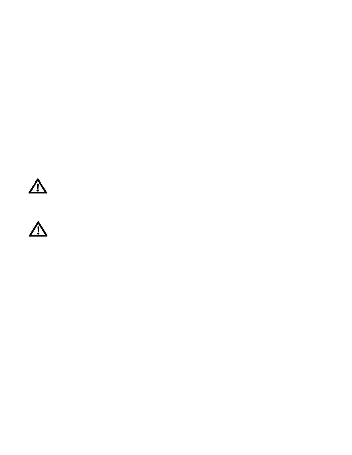
A child or adult can tip the range and be killed. In-
stall the anti-tip device to the structure and/or the
range. Verify the anti-tip device has been properly
installed and engaged. Engage the range to the
anti-tip device by ensuring the anti-tip device is re-
engaged when the range is moved. Re-engage the
anti-tipdeviceiftherangeismoved.Donotoper-
ate the range without the anti-tip device in place and
engaged. See installation instructions for details.
Failure to do so can result in death or serious burns
to children or adults.
If this range is removed for any reason, (eg. service
or cleaning), it must be replaced as outlined before
placing the range back in operation.
Levelling a Free-Standing Range
All free-standing ranges must be level to obtain
proper cooking results. The leveling legs should be
screwed into the corner brackets. Place pan or mea-
suringcuppartiallylledwithwateroralevelonthe
oven rack. Adjust the leveling legs until the range is
level. The top of the side panels should be level with
the counter top.
Making sure the anti-tip brackets are installed:
•Sliderangeforward.
•Lookfortheanti-tipbracketsecurelyattachedto
oor.
•Sliderangebacksorearrangefootisunderanti-
tip bracket.
INSTALLATION INSTRUCTIONS
16
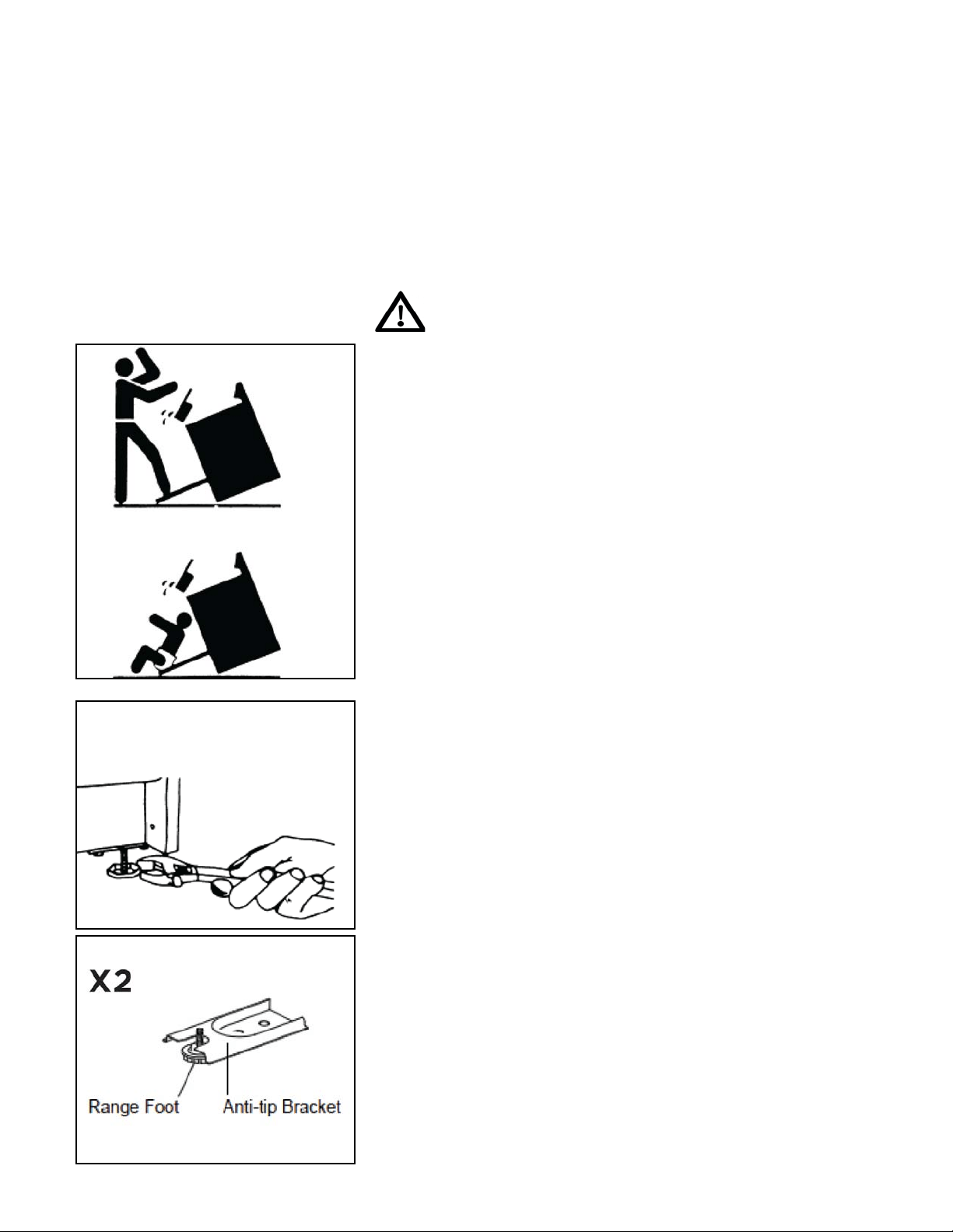
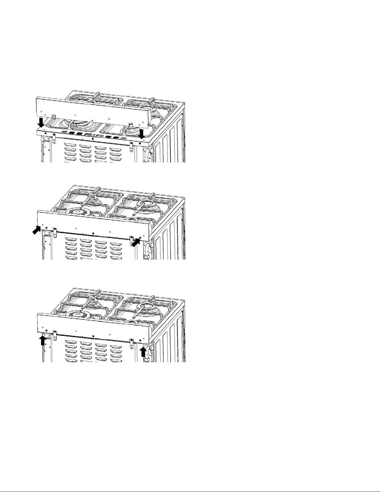
1. Align the backsplash to the rear part of
the cooktop as shown in the diagram.
2. Secure the backsplash to the cooktop
from the back using the 2 Philips head
screws provided as shown in the diagram.
3. Secure the backsplash from the bottom
using the Philips head screws provided as
shown in the diagram.
HOW TO INSTALL THE BACKSPLASH

17
NOTICE TO MASSACHUSETTS APPLIANCE DEALERS:
Be sure this document is included in all gas range appliances sold to consumers in
the State of Massachusetts.
NOTICE: Massachusetts law requires the following:
•Appliancesmustbeinstalledbyalicensedplumberorgastter.
•Appliancesmustbeconnectedwithathree(3)foot(36”maximumlength)exible
gas connector and
•A“T”handletypemanualgasvalveinthegassupplylinetotheappliance.
Have the dealer where you purchase your new range install it or have him rec-
ommendaqualiedinstaller.Installationmustconformwithlocalcodes.Inthe
absence of local codes, the installation must conform with the National Fuel Gas
Code, ANSI Z223.1-Latest Edition in the U.S.A. or the CAN/CGA B149.1 or .2 In-
stallation Codes in Canada.
The range should be connected to the supply line with 1/2-inch black iron pipe or
acertiedexibletyperangeconnector.Topreventgasleaks,putanapproved
sealingcompound,whichisresistanttoliqueedpetroleumgases,onallthreaded
connections.
Important: Donotapplypressuredirectlytotherangemanifoldpipewhentighten-
ing supply connections. The manifold pipe should be held securely at the pressure
regulator to prevent twisting. Hold the pressure regulator with a wrench during the
tightening of the connection, or the manifold pipe may be twisted and split, and
cause a dangerous leak.
The installation of ranges designed for manufactured (mobile) home installation
must conform with the Manufactured Construction and Safety, Title 24 CFR, Part
3280, [formerly the Federal standard for Mobile Home Construction and Safety,
Title24,HUD(Part280)]intheU.S.A.orC.S.A.StandardCAN/CGAZ240.4.2in
Canada or, when such standards are not applicable with local codes.
The installation of ranges designed for recreational vehicle installation must con-
form to state or other codes and in the absence of such codes with the standard
for recreational vehicles ANSI A119.2.2–1982 in the U.S.A. or CAN/CGA Z240.4.2
in Canada. The installation of appliances designed for recreational park trailers
must conform to recreational park trailers, ANSI A119.5.
Note: Checkallpipingconnectionsintheunitforleaks.Neveruseanopename
to check for gas leaks. Use a soap solution with a recommended ratio of 75%
water and 25% dish washing soap. It’s possible for connections made at the fac-
tory to leak, due to vibration encountered in transportation. Make certain you have
checked them all, and repair any connections that leak.
GAS CONNECTIONS (All Units)
18
The appliance and its individual shut-off valve must be disconnected from the gas
supply piping system during any pressure testing of that system at test pressures
in excess of
1
/
2
psig.
The appliance must be isolated from the gas supply piping system by closing its
individual manual shut-off valve during any pressure testing of the gas supply
piping system at test pressures equal to or less than
1
/
2
psig.
•Gaslineshut-offvalve
•Toreducethepossibilityofgasleaks,apply
Teontapeorathreadcompoundapproved
for use with LP or Natural gases to all threaded
connections.
•Useaexibleapplianceconnectortoconnect
your gas supply to the appliance. A 3 foot length
is recommended for ease of installation but
other lengths are acceptable. Never use an old
connector when installing a new range.
•Checkforleaksusingaleakdetectororsoapy
water with a recommended ratio of 75% water,
25% dish washing soap.
Installation
It is the responsibility of the installer to make
certain that the range is properly adjusted at the
time of installation. Situations caused by improp-
er adjustments or improper installation are not
covered under the warranty. Any expenses incurred due to such situations will not
be paid by the manufacturer of the appliance.
Connecting gas to range
This range is designed to operate at a pressure of 5” of water column on natural
gas (NG) or 10” of water column on propane gas (LPG).
Make sure you are supplying your range with the type of gas for which it is de-
signed. This range comes equipped from the factory equipped for use with
NG (natural gas). This range is convertible for use on propane (LPG) also (pro-
paneoricesincludedinthepackaging).
GAS CONNECTIONS (continued)

19
WhenusingthisonLPGgas,conversionmustbemadebyaqualiedLPGinstall-
er before attempting to operate the range on that gas.
For correct operation, the pressure of natural gas supplied to the regulator should
be between 4” and 5” of water column. For LP gas, the pressure supplied must be
between 10” and 12” of water column.
When checking for correct operation of the regulator, the inlet pressure must be at
least 1” more than the operating -manifold- pressure as given above. The pressure
regulator located at the back of the range manifold must remain in the supply line
regardless of whether natural or LP gas is being used.
Regulator is only good for psi (14” w.c.) so test pressure must not exceed
1
/
2
” psi.
Shut off the main gas supply valve before removing the old range and leave it off
until the new hook-up has been completed.
Because hard piping restricts movement of the range, the use of a CSA/ETL cer-
tiedexiblemetalapplianceconnectorisrecommendedunlesslocalcodesre-
quire a hardpiped connection. Never reuse an old connector when installing a new
range. If the hard piping method is used, you must carefully align the pipe; the
range cannot be moved after the connection is made.
To prevent gas leaks, use pipe joint compound resistant to LP or NG gases (de-
pending on set up) on all male -external- pipe threads.
1. In an easily accessible location, install a service manual gas shut off valve. Be
sure everyone operating the range knows where and how to shut off the gas
supply to the range.
2. When all connections have been made, be sure all range controls are in the off
position and turn on the main gas supply valve. Check for gas leaks by using a
soap and water solution. If a gas leak is present, shut off gas immediately, tight-
en all connections, and retest for leaks.
3.Anyopeninginthewallbehindtheapplianceandintheoorundertheappli-
ance must be sealed.
After installation:
1. Check ignition of cooktop burners.
2. Check ignition of oven burner.
3. Check ignition of broiler burner.
4.Checkforgasleaksatallgasconnections(usingagasdetector,neveraame)
GAS CONNECTIONS (All Units)
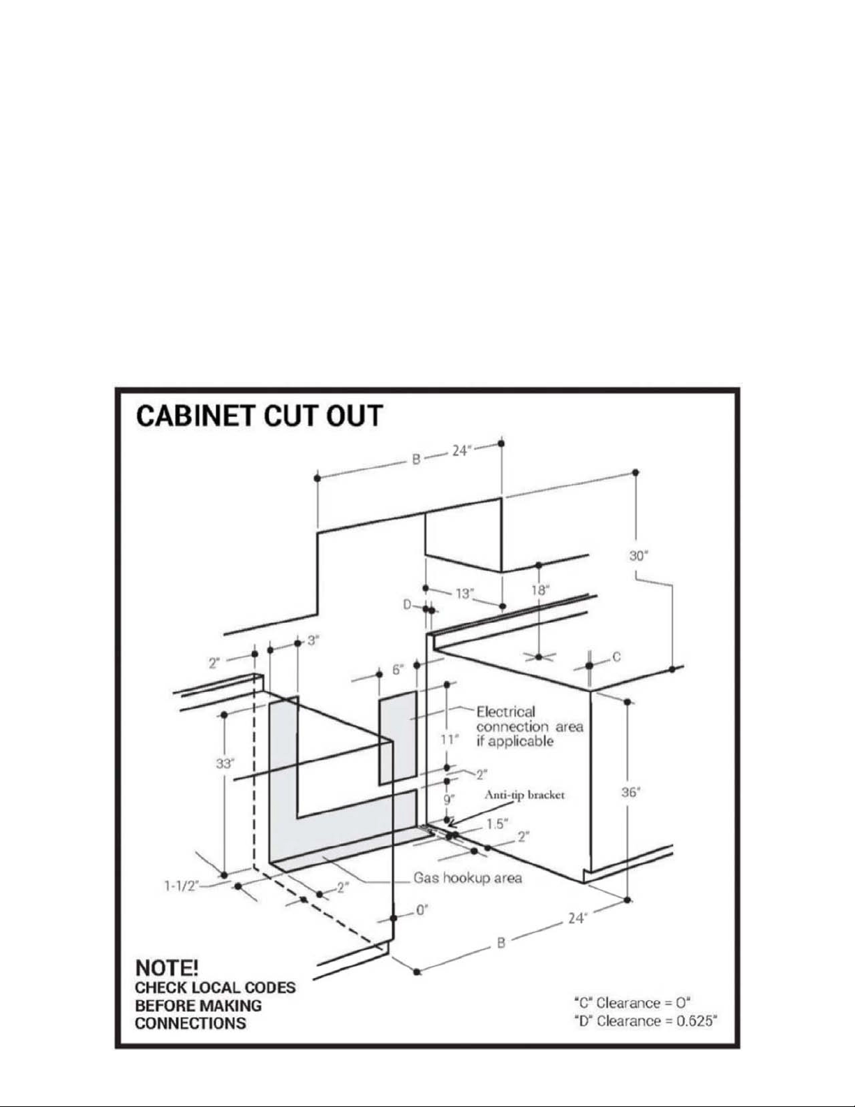
20
All units must be installed in accordance to minimum rear and side wall clearance
and clearances extended vertically above cooking top which are stated on the se-
rial plate located at the back of the range.
ANYOPENINGSINTHEWALLBEHINDTHEUNITANDINTHEFLOORUNDER
THEUNITMUSTBESEALED.
Note.DuetopotentialhazardsitisrecommendedthatstoragecabinetsNOTbe
installed above the cooking surface.
INTHEEVENTOVERHEADCABINETSAREINSTALLED,THEMAXIMUM
DEPTHOFCABINETSINSTALLEDABOVECOOKINGTOPSSHOULDBE13”.
WALL CLEARANCES
21
WALL CLEARANCES (continued)
22
To convert application and/or adjust from NG to LPG
The range is set for use with Natural Gas (NG). The factory setting is indicated on
the serial plate. When set for Natural Gas operation, the pressure regulator will
regulate the gas to 5 inches water column pressure. When set for Liquid Propane
Gas (LPG) operation, the pressure regulator will regulate the pressure to 10 inches
water column.
Natural Gas to Liquid Propane Gas Conversion
Theconversionkitmustbeinstalledbyqualiedserviceagency.
WARNING: Please ensure before beginning converting the appliance that the gas
supply is shut off and the electrical connection is disconnected. Failure to do can
result in injury or property damage.
GAS RANGE CONVERSION
“Thisconversionkitshallbeinstalledbyaqualiedserviceagencyin
accordance with the manufacturer’s instructions and all applicable codes
and requirements of the authority having jurisdiction. If the information in
theseinstructionsisnotfollowedexactly,are,explosionorproductionof
carbon monoxide may result in property damamge, personal injury or loss
oflife.Thequaliedserviceagencyisresponsiblefortheproperinstallation
of this kit. The installation is not proper and complete until the operation
oftheconvertedappliancesischeckedasspeciedinthemanufacturer’s
instructions supplied with the kit.”
ATTENTION: YOUR PRODUCT IS PRE-INSTALLED WITH NATURAL GAS
INJECTORS AND REGULATOR.
IF YOU ARE USING LP GAS, PLEASE REFER TO THE INSTALLATION
INSTRUCTIONS INCLUDED WITH THE CONVERSION KIT.
Natural Gas Orifices
BTU 2,700 5,000 11,000 8,500 7,000 8,200
BURNER Auxiliary
Burner
Semi-Rapid
Burner
Triple Burner Rapid Burner Broil Burner Oven Burner
POSITION Front Right Back Left Back Right Front Left
ORIFICE 0.73 1.0 1.5 1.3 1.24 1.3
Liquid Propane Gas Orifices
BTU 2,700 5,000 11,000 8,500 7,000 8,200
BURNER Auxiliary
Burner
Semi-Rapid
Burner
Triple Burner Rapid Burner Broil Burner Oven Burner
POSITION Front Right Back Left Back Right Front Left
ORIFICE 0.53 0.68 1.0 0.9 0.8 0.82
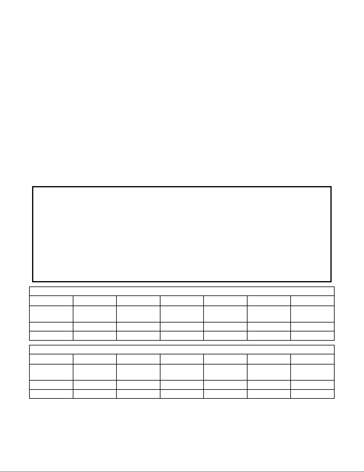
23
MODEL NUMBER: UGP 24V PC1 S/S
Parts List: 1.Orices 2.Screwdriver
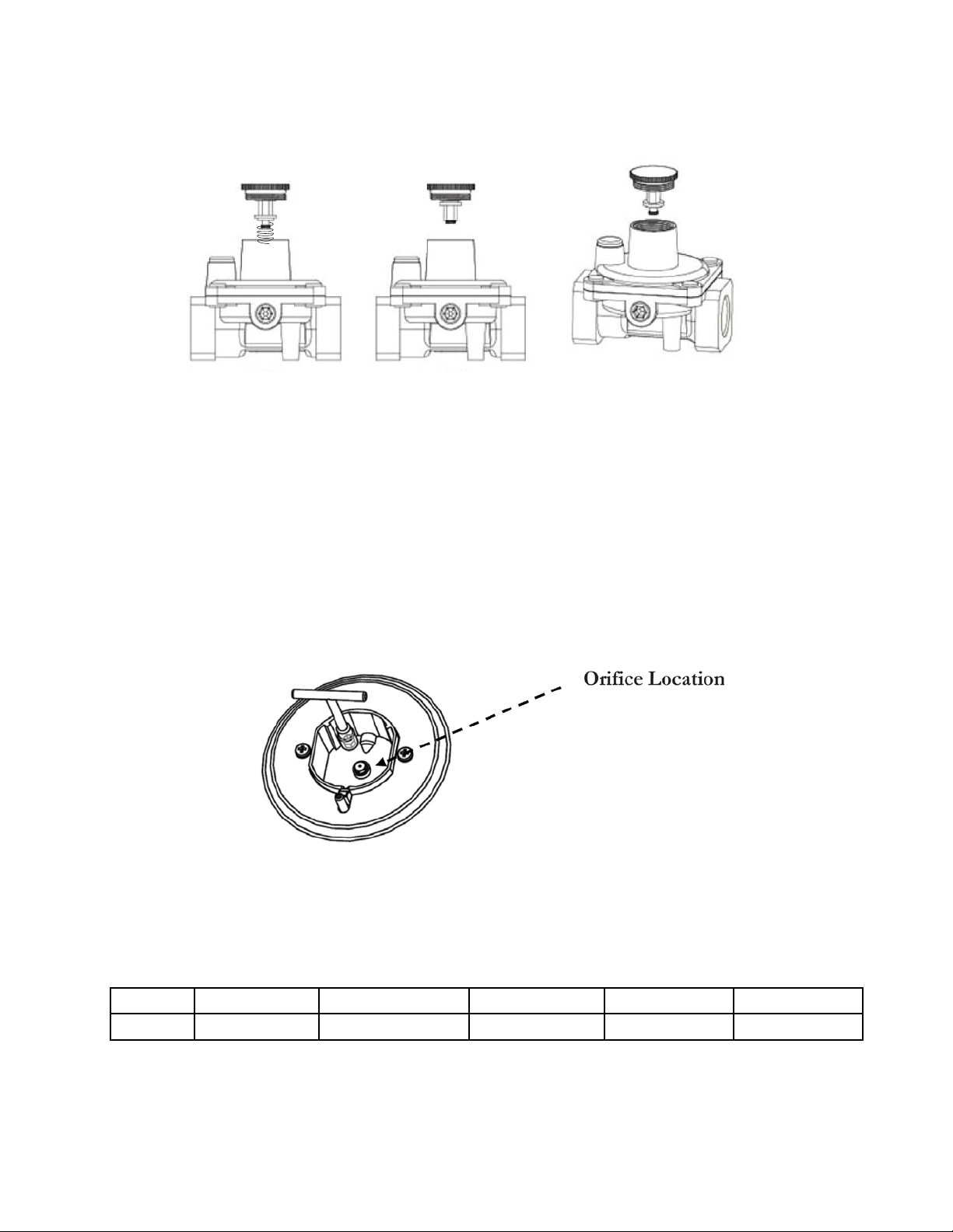
Convertible Pressure Regulator
TherangeisshippedtooperateonNG.LPGoricesandaspecialscrewdriverfor
adjustingtheminimumameareshippedwiththeunitinaseparateenvelopewith
the manual. The inlet pressure of the gas supply shall be in accordance with the
nominal inlet pressure of the regulator used on the range or 1/2 psig maximum.
The range should be tested by pressurizing the regulator with an inlet pressure at
least1inchwatercolumnabovethemanufacturer’sspeciedmanifoldpressure
shown on the serial plate.
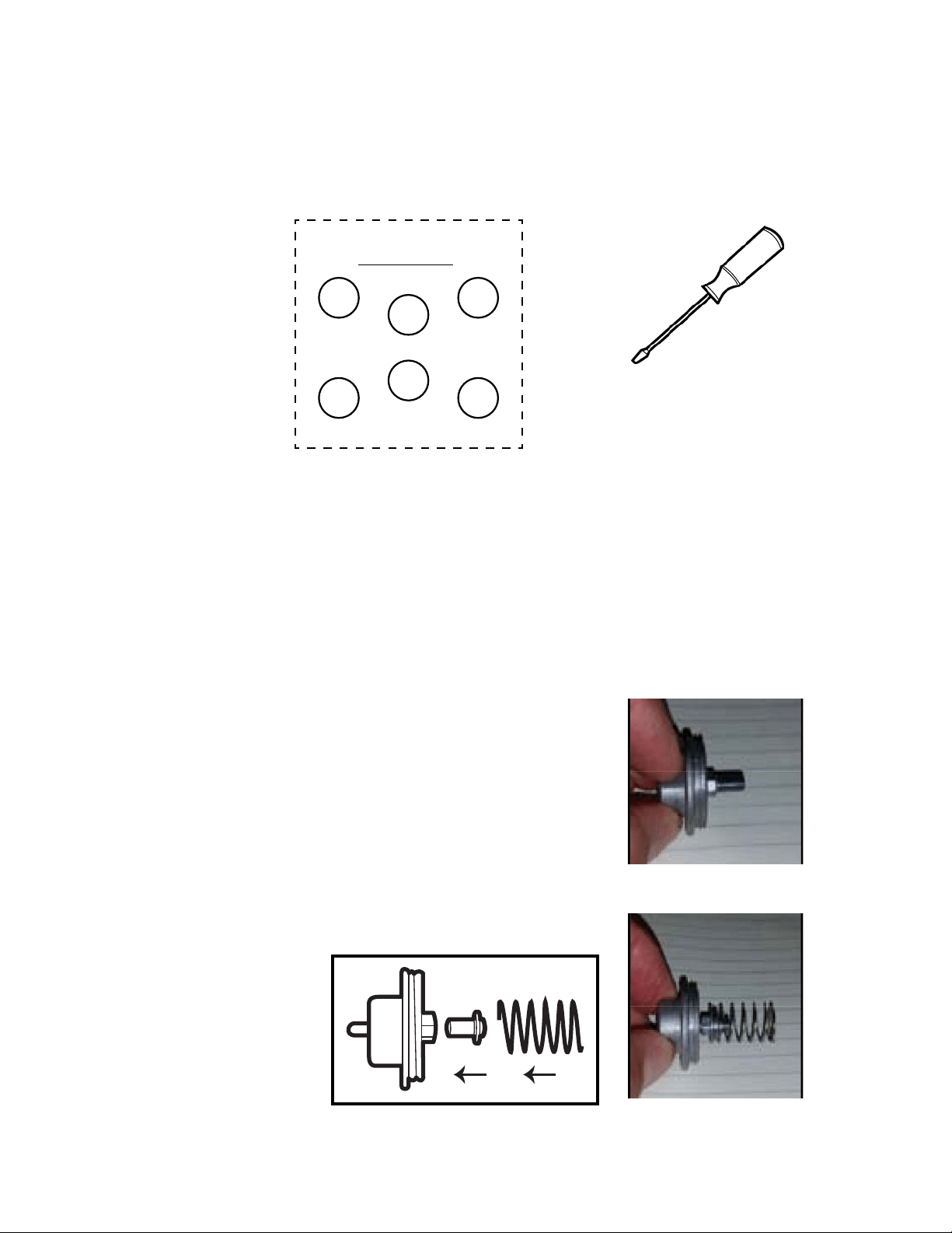
1. CAUTION: Before proceeding with the conversion,
shut off the gas supply to the appliance prior to dis-
connecting the electrical power
2. Locate convertible regulator at the back of the range,
left side facing appliance. Remove cap and pop out
the pin that’s attached
3. On the side you will see the pin positon for use
with LPG
4.Unscrewpinandip
it to the LPG position
- short end outwards,
spring on outside.
GAS RANGE CONVERSION
UGP-24V PC1 S/S
RL
OVEN
NOZZLE (LPG)
0.68
FL
0.9
RR
1.0
FR
0.53
0.82
BROILER
2”
2”
0.8
NG
LPG
24
5. Replace the cap back on the regulator
6. Remove the grates, burners and burner caps from the range to
accesstheorices.
7.Usea7mmwrenchtoremovetheorices.Eachoricecanbe
accessedeasily-thelargerburneroriceislocatedontheburnerwall.
Burner Orice
8.RemoveallNGorices,placeinthebagandstoreinasafeplace.
9.TaketheLPGoricesprovidedandinstallthemasshownbelow.
See below for rating of orice for each model
Smallest Medium x 2 Largest Oven Broil
LPG 0.53 mm 0.68/0.9 mm 1.00 mm 0.82 mm 0.8 mm
10.Oncealltheoricesareinstalled,replaceallburnersandburnercaps,thenre
uptheburnerstochecktheminimumameheight.
GAS RANGE CONVERSION
LPG NG
25
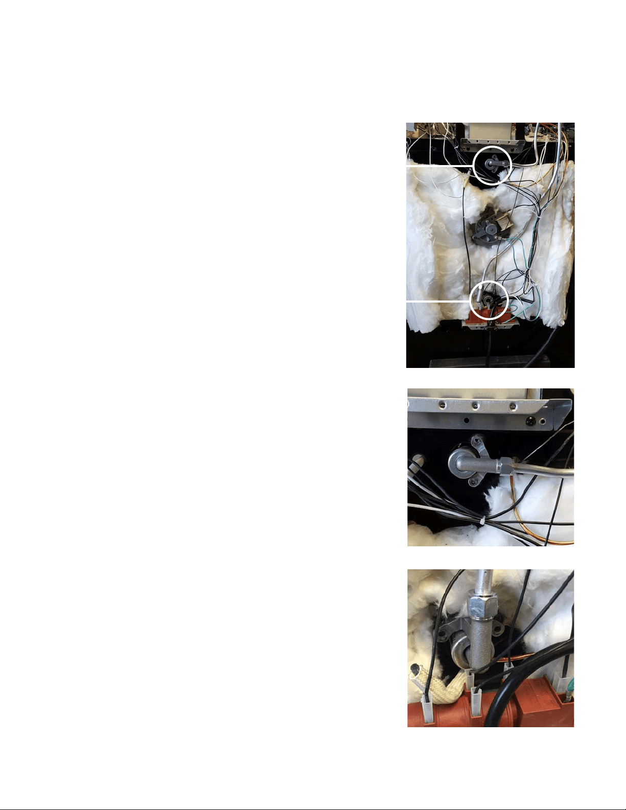
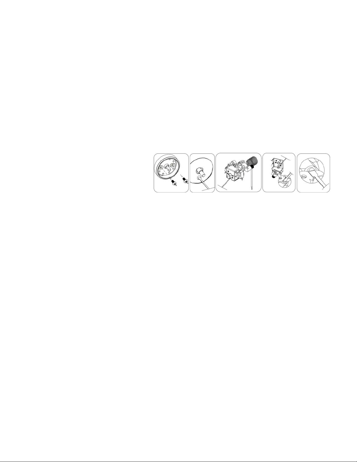
To replace the oven burner orice
1. Remove the back panel
2.Locate/disconnectovenoricehousing
screws x 2 (Fig 1)
3. Gently bend gas tube to gain access to the
orice
4.Usea7mmsockettoremoveoriceand
replacewithspeciedoriceforgasconver-
sion
5.Remountovenoricehousingscrewsx2
To replace the broiler burner orice
1.Locate/disconnectbroiloricehousing
screws x 2
2. Gently bend gas tube to gain access to the
orice(Fig2)
3.Usea7mmsockettoremoveoriceand
replacewithspeciedoriceforgasconver-
sion
4.Remountbroiloricehousingscrewsx2
5. Replace back panel
Note: Check for leaks using a leak detec-
tor or soapy water with recommended ratio
of 75% water, 25% dish washing soap.Once
you have completed the conversion, check
the operations of ignition making sure each
ofthe4burners,pilotameandovenburner
amearefunctioningcorrectly.Pleaserefer
to pages 30 through 35.
GAS RANGE CONVERSION
(Fig 1. Broiler)
(Fig 2. Oven)
OVEN
BROILER
26
CHECKING FOR MANIFOLD GAS PRESSURE
To check the manifold gas pressure, remove the burner cap and connect a ma-
nometer(watergauge)orotherpressuretestdevicetotheburnerorice.Usea
rubber hose with inside diameter of approximately ¼” hold the end of the hose tight
overtheorice.Turnthegasvalveon.Foramoreaccuratepressurecheck,have
at least two (2) other top burners burning. Be sure that the gas supply (inlet) pres-
sureisatleastoneinchabovethespeciedmanifoldpressure.Maximumgassup-
ply pressure must not exceed 14” inch water column, minimum gas supply pres-
sure must be 1” inch water column above recommended pressure, 12” for propane
gas, and 5” water column for natural gas. When properly adjusted the manifold
water column pressure is 10” for LP/propane gas or 5” for natural gas.
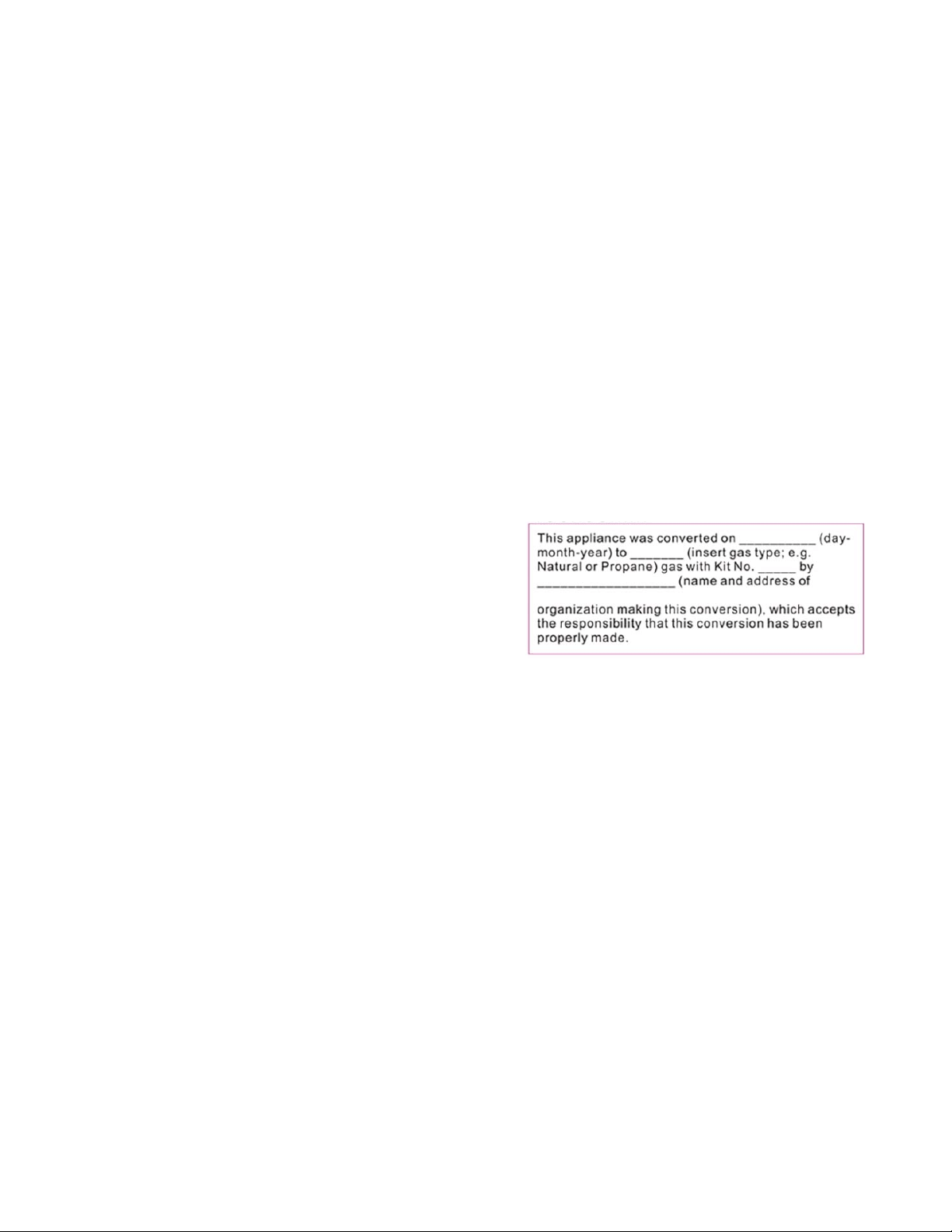
Note:Oncetheunithasbeenconvertedllouttheincludedstickerandplaceiton
the back of the range
Once you have completed the conversion,
check the operations of ignition making sure
eachofthe4burners,pilotameandoven
burneramearefunctioningcorrectly.Please
refer to pages 30 thru 35 – Operation of
Range.
High Altitude Applications above 2000 feet: At elevations above 2,000 feet, the
range must be derated 4% for each 1,000 foot above sea level. It is the installer’s
responsibility to see that the range’s input rate is adjusted properly.
GAS RANGE CONVERSION
27
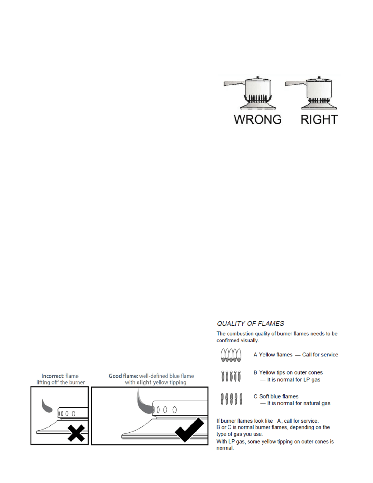
ADJUSTING THE TOP BURNER AND OVEN FLAME
Keep appliance area clear and free from combustible materials, gaso-
line, and other ammable vapors and liquids. Do not obstruct the ow
of air that is necessary for combustion and ventilation.
Top Burner Valves
Thetopburnershaveoricesthatarededicatedtothetypeoffueltobeused.
Theseoricesarenotadjustable.Theymustbechangedcompletelytoconvert
fromonegastotheother.DONOTDISCARDTHEUNUSEDORIFICES.They
should be saved in order to convert the range back to its original fuel.
Whenconvertingthegasvalves,theminimumameadjustmentscrewmustbe
adjusted.
Pleaseseethesuppliedscrewdriverintheconversionkitalongwiththeorices.
Theproperamesizeisapproximately¼”obtained.–seeadjustmentprocedure
below.
Theproperlyadjustedmaximumameisapproximately3/4”highandhasthree
distinct cones; the kindling point, the dark blue center cone, and the outer mantel.
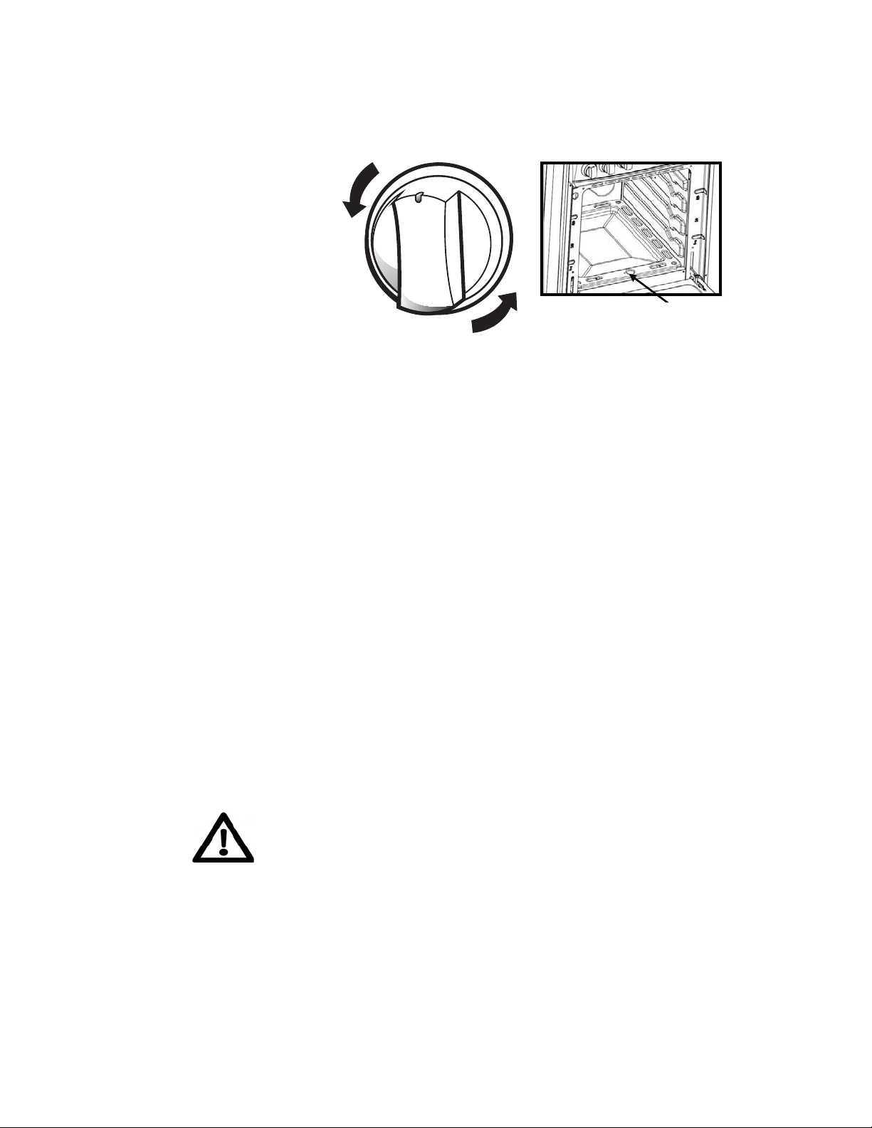
ADJUSTING THE TOP BURNER FLAME
1. Ensure the range has gas supply and power
2. Light the burner
3. Set the top burner valve to the minimum position
4. Remove the knob by pulling straight out
5. Locate the bypass screw behind the
left screw (see illustration)
Remove the left screw
Inserttheatheadscrewdriver
(2.5mm x 75mm - provided) into
the screw hole and turn the by
passscrewclockwisetoadjusttheame
Donotovertighten
6. Replace the knob
7. Repeat for each of the other burners
28
Cooktop Burner Operation
Thetopburneramesizeshouldbeadjustedso
that is does not extend beyond the edge of the
cookware. As a matter of safety, it’s recommended
that you comply with these instructions.
Ahighameonasurfaceburnerisbothinefcientandunsafe.Theameshould
always be adjusted so that it is no larger than the bottom of the pan. Fluctuations
inamesizecouldbecausedbypressurevariations,improperlypositionedburn-
ers, damage or debris.
To light a burner, press the burner knob in and turn counter clockwise to
highame/ignitionposition.Youwillheartheelectronicignitionclickingas
youcontinuetoholdtheknobdownuntiltheamelights.ALLelectrodeswillspark
at a rate of approximately 2 ½ pulses (sparks) per second. Once the burner
is lit, hold in for a few extra seconds to warm up the thermocouple so the
electromagnet in the burner valve stays in the open position once you release.
Continue to hold the knob depressed until gas ignites at the burner. Adjust the in-
tensity of top burner heat in the same manner described above.
Note: In the event the electronic ignition system fails, the top burners and oven
pilot can be lit by holding a lighted match near the burner head and turning the
appropriate top burner knob to the “9 o’clock position”.
TOP BURNER HEIGHT
ADJUSTING THE TOP BURNER AND OVEN FLAME
(continued)
incorrect and good flame patterns
29
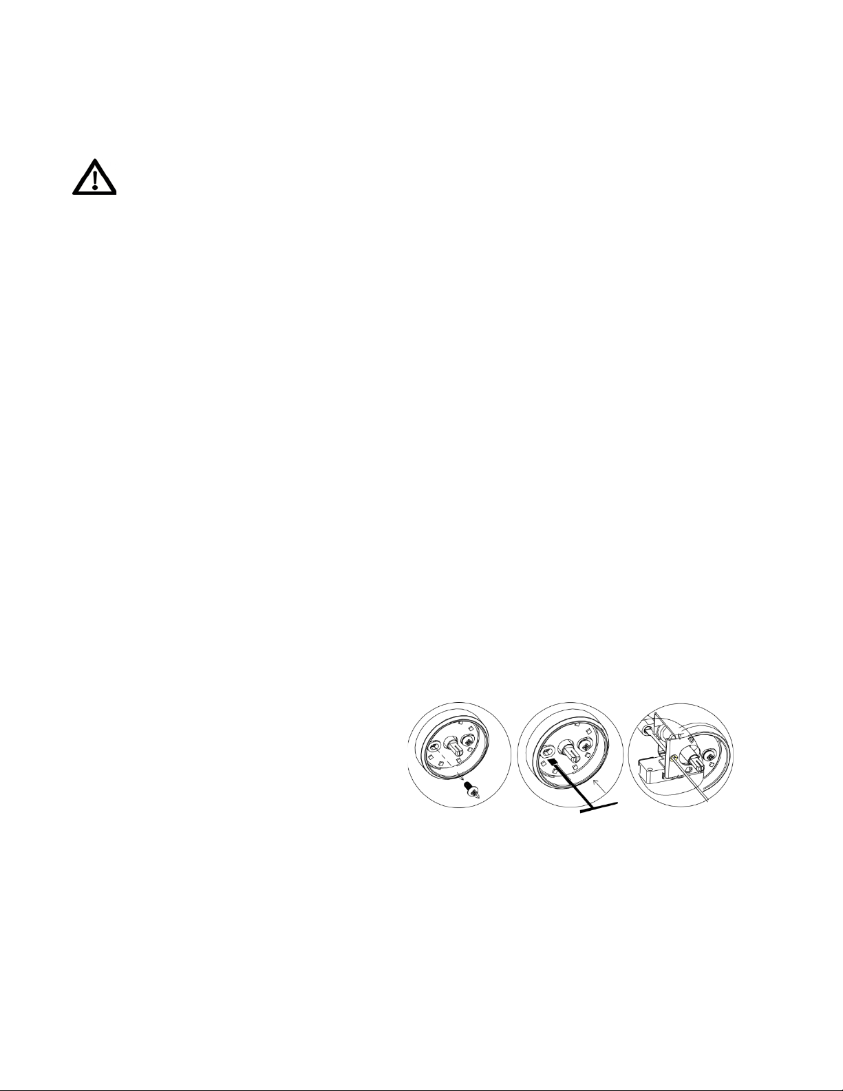
ADJUSTING THE OVEN BURNER FLAME
1) Light the burner by turning the thermostat to the 500ºF position,
2) Remove the knob by pulling straight out.
3) Remove the two (2) Philips head screws that secure the bezel to the control
panel.
4) Carefully lift the bezel away from the control panel to allow access to the access
hole below the valve stem. (see illustration).
5)Inserttheatheadscrewdriver(2.5mmx75mm)intothescrewholeandturn
the bypass screw clockwise to
adjusttheame.
DONOTOVERTIGHTEN.
6) Mount the knob to the valve stem.
7) Allow the oven to heat up for approximately 10 minutes then rotate the knob to
the 300ºF position to operate the thermostat by-pass. Slowly screw the by-pass
screwuntilyouobtainaameofapproximately3–4mminheight.
8) Carefully replace the bezel and knob ensuring not to damage wires.
OVEN VALVE
Theovencontrolhasaamesafetydevicebuiltintothebodyofthethermostat.
Presenceofagasignitionsource(pilot)isveriedbyaamesafetyprobe.This
amesafetyprobeactuatestheinternalsafetydevicetoallowgasintotheoven
burner when the oven is turned on. If there is a loss of gas ignition during opera-
tion,theamesafetydevicewillcloseoffgasowtotheovenburnerandpilot.
Theovenburneroriceislocatedonabrassinjectorstudattherearoftheoven
undertheovenoor.Thisoriceisdedicatedtothegasforwhichtheovenistobe
used.Theoriceisnotadjustable.Itmustbechangedcompletelytoconvertfrom
onegastotheother.DONOTDISCARDTHEUNUSEDORIFICE.Itshouldbe
saved in order to convert the range back to its original fuel
ADJUSTING THE TOP BURNER AND OVEN FLAME
(continued)
30
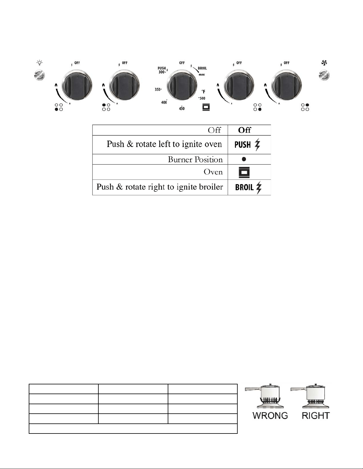
Lighting the Top Burners
1.Toobtainaamemoreeasily,lighttheburnerbeforeplacingacooking
utensil on the burner grate.
2.Decidewhichburneryou’reignitingrstusingthescreeneddiagrambelow
the burner knob. The black dot indicates the position of the burner you’re
igniting.
3.To light a burner, press the burner knob in and turn counter clockwise to
highame/ignitionposition.Youwillheartheelectronicignitionclickingas
youcontinuetoholdtheknobdownuntiltheamelights.Oncetheburner
is lit, hold in for a few extra seconds to warm up the thermocouple so the
electromagnet in the burner valve stays in the open position once you release.
4.Afterlightingtheame,turnthecontrolknobtoadjusttheamesizeas
required.
Choice of Burner
DIAMETERS OF PANS WHICH MAY BE USED ON THE TOP BURNERS
BURNER MINIMUM MAXIMUM
Auxiliary 4” 23/32 (12 cm) 5” 1/2 (14 cm)
Semi-rapid 6” 19/64 (16 cm) 9” 7/16 (24 cm)
Rapid 9” 7/16 (24 cm) 10” 15/64 (26 cm)
Do not use pans with concave or convex bases
OPERATION OF RANGE
31
OPERATION OF RANGE
(continued)
HOW TO USE THE GAS OVEN
General features
The gas oven is provided with two burners:
The Oven burner, mounted on the lower part of the oven
The Broil burner, mounted on the upper part of the oven
Using the oven for the rst time
It is advised to follow these instructions:
- Insert shelves and broiler grid and tray
-Turntheovenontothemaximumtemperatureposition(500˚F)toeliminatepos-
sible traces of grease from the oven burner. The same operation should be
followed for the Broil burner (knob on position BROIL).
- Unplug the power cord, let the oven cool down, then clean the interior of the oven
with cloth soaked in water and detergent (neutral) then dry carefully.
OVEN BURNER
Performs the normal “oven cooking” function.
-Thegasowtotheburnerisregulatedbyathermostatwhichmaintainsthe
desired oven temperature.
- The control of the temperature is determined by a thermostatic probe positioned
inside the oven.
- The probe must be always kept in its housing, in a clean condition, as an
incorrect position or a dirty probe may cause improper control of the temperature.
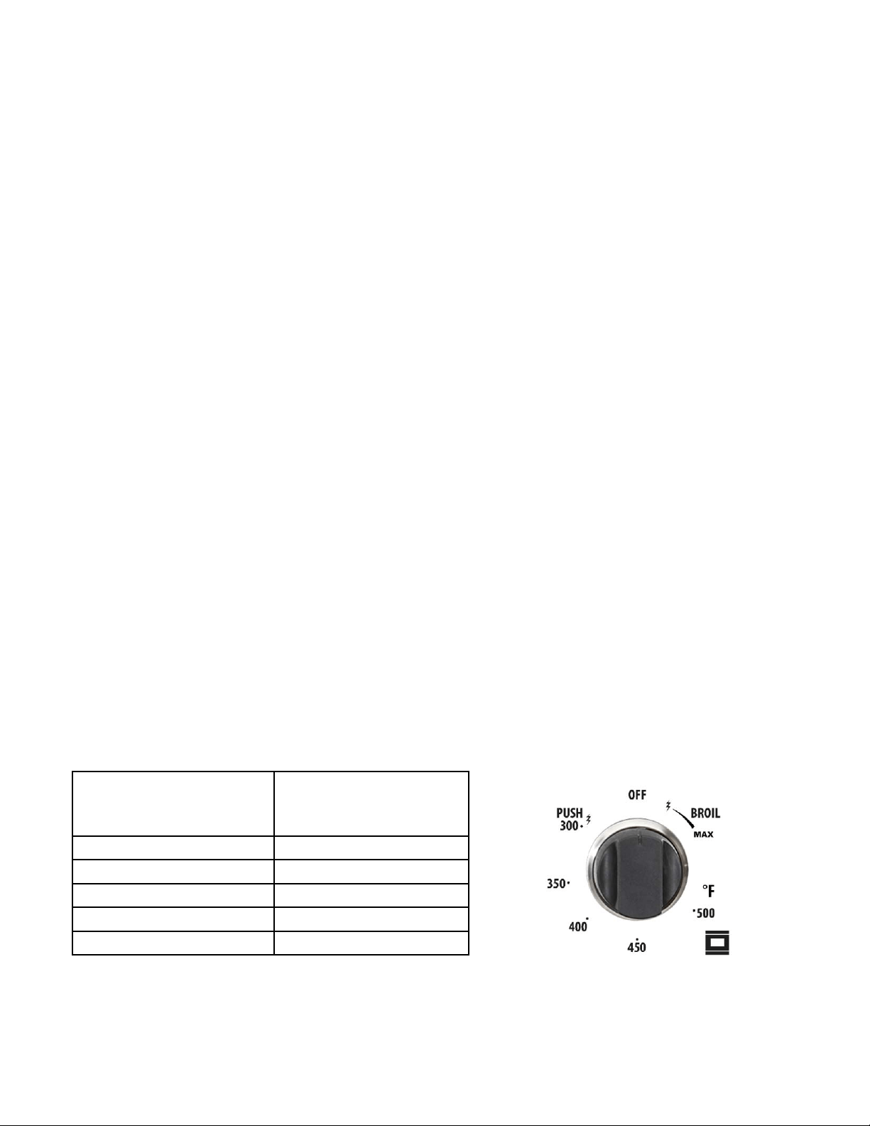
GAS OVEN SETTING
Number printed
on the knob
(temperature in ˚F)
Corresponding
temperature in ˚C
300 149
350 177
400 204
450 232
500 260

32
OPERATION OF RANGE
(continued)
OVEN THERMOSTAT
- The numbers printed on the control panel indicate the increasing oven
temperature value (°F).
- To regulate the temperature, set the chosen number onto the control knob
indicator.
- The position BROIL serves only to turn on the broil burner.
NOTE: When the range will not be used for long periods of time, set the gas knobs
to their OFF positions and also close the gas shut-off valve placed on the main gas
supply line.
VERY IMPORTANT: The oven/broil shall be used always with the door
closed.
VERY IMPORTANT: Never obstruct the oven vent slots on the backsplash.
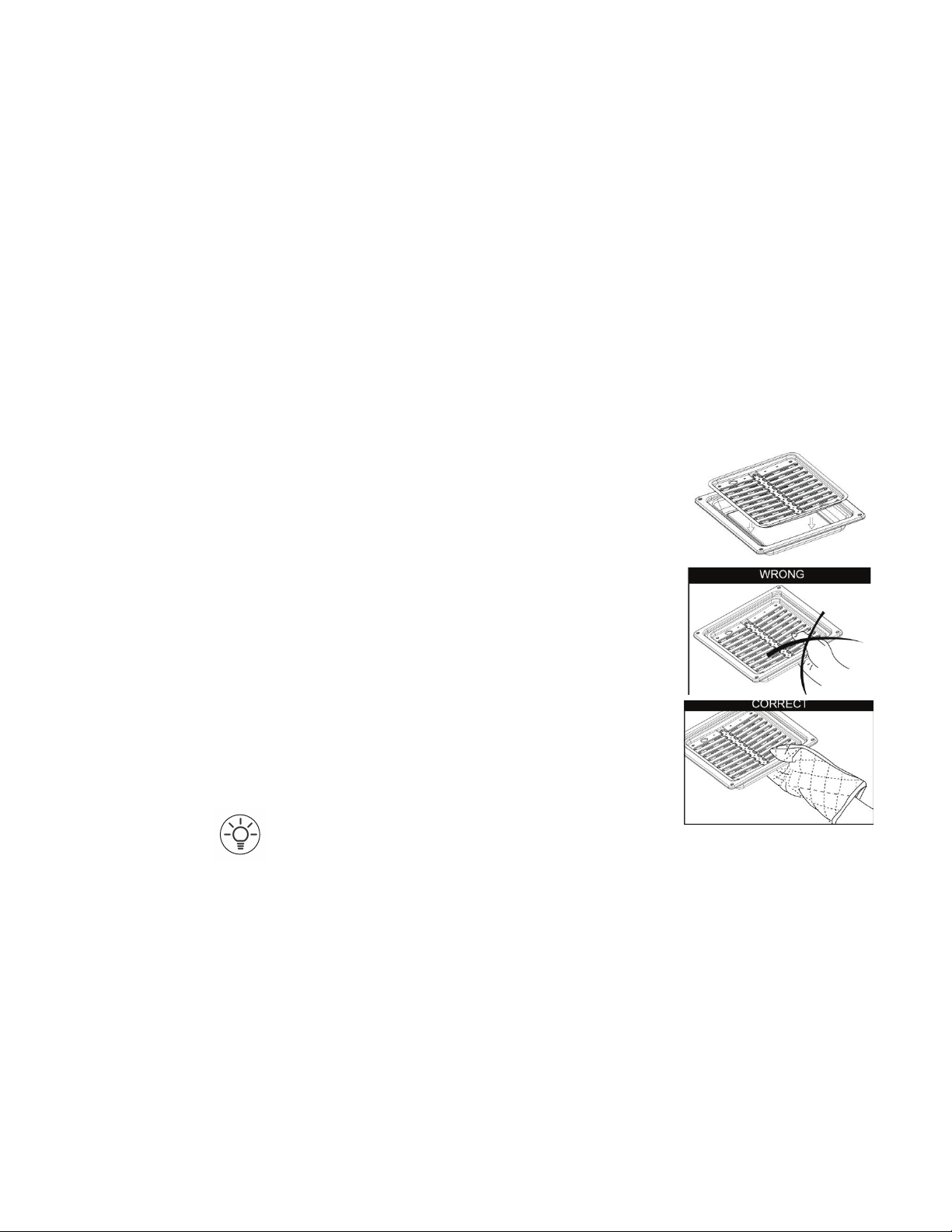
-Donotbroilwithoutusingthebroilingpan.
- Important: Use always suitable protective gloves when inserting / removing the
broiling pan, shelves, pans on other cooking utensils from the oven.
- Attention: the range becomes very hot during operation
- Attention: the oven door becomes very hot during operation; be sure to use
the handle to open/close.
- Keep children away from the stove/oven when it is in use.
IGNITION OF THE OVEN BURNER
The thermostat allows the automatic control of the temperature.
The gas delivery to the oven burner is controlled by a two way thermostatic tap
(ovenandbroilburners)withame-failuredevice.
To light the oven burner operate as follows:
1. Open the oven door to its full extent.
WARNING: Risk of explosion! The oven door must be open during
this operation.
2. Lightly press and turn the thermostat knob counter-clockwise to max position or
500ºF.
OPERATION OF RANGE
(continued)
3. Press the knob inward and
hold to activate the electronic
ignition. Note that you will
hear a “clicking” noise. Hold
the knob pressed inward until
the oven burner is lit. Once
the oven burner is lit, release
the knob.
In case of power outage, you can manually light the burner by pressing the knob
inward and immediately approach a lighted match to the opening “A” (see the dia-
gram above).
Never continue this operation for more than 15 seconds. If the
burner has still not ignited, wait for about 1 minute prior to
repeating the ignition.
4.Whenusingtherangeforthersttimeorafterlongperiodofnon-usage,keep
pressing the knob inward for approximately 10 – 15 seconds after the burner has lit
to ensure the gas valve has been accurately primed.
5. Close the oven door slowly and adjust the burner accordingly to the desired
temperature.Iftheameextinguishesforanyreason,thesafetyvalvewillauto-
matically shut off the gas supply to the burner.
Tore-lighttheburner,rstturntheovencontrolknobtotheOFFposition,waitfor
at least 1 minute and then repeat the lighting procedure.
Attention: the oven door becomes very hot during operation. Keep
children away.
MOISTURE IMPORTANT
If sparking does not occur when the oven thermostat knob is turned on during the
initialattempttouse,orafterseveraldaysofnon-use,itCOULDBEtheresultof
moisture build-up in the ceramic sleeve of the oven electrode. This may happen in
areas with high humidity, or if food having high water content is cooked. This mois-
ture can be driven out of the ignitor by lighting the pilot and operating the oven for
a few minutes.
A
33

OPERATION OF RANGE
(continued)
CONVECTION MODE
Heat is transferred from the bake burners in the bottom of the oven cavity to the
oven cavity itself. The convection fan in the rear of the oven then circulates the hot
air, providing even heat distribution throughout the oven. Convection cooking gen-
erally provides a more even temperature with faster baking times than the standard
oven baking setting. This mode is controlled by a button on the right hand side of
the control panel. Simply push the button in to activate it.
•Positiontheoven’sbottomcoverandtheovenshelf/shelvesbeforeusingthe
oven. Use more than one oven shelf for larger baking loads. Remove any unused
shelves and baking utensils from the oven.
•Preheattheoventothetemperaturestatedintherecipebeforebaking.Depend-
ing on the temperature needed and the size of the oven, preheating will take 15 -
20 minutes.
•Arrangepansandfooditemsevenlyontheshelves.Makesurepansdonot
touch each other or the sides of the oven. When baking a single item, always cen-
ter the item on the oven shelf, preferably in the center of the oven. If baking on
multiple shelves, make sure to stagger items on the shelves so that one is never
directly above another.
NOTES ABOUT CONVECTION COOKING
Convection cooking generally provides a more even temperature with faster baking
times than the standard oven baking setting. When baking in Convection Mode,
either reduce the temperature stated in the recipe and leave the baking time un-
changed, or reduce the baking time by several minutes and leave the temperature
unchanged. For foods with a baking time of over an hour, reducing both the tem-
perature and the time slightly may give the best results.
•Darkmetalbakingpansorthosewithadullnishabsorbheatfasterthanshiny
pans, and are excellent for pies, breads and anything that needs browning or a
crisper crust.
•Shinynishorlightcolouredpansmayworkbestforfoodsthatrequirelighter,
moredelicatebrowningoracrispercrustastheyreectsomeheat,creatingaless
intense baking surface.
•Avoidopeningtheovendoorfrequentlyduringbakingasthisaffectstemperature
andefciency.
34
35
OPERATION OF RANGE
(continued)
CONVECTION ROASTING
When convection roasting, it is important that you use a broiler pan for best con-
vection roasting results. A broil/roast pan (with a rack) elevates the roast to allow
the hot air to circulate around the meat, sealing in juices for a moist and tender
roast with a richly browned exterior (similar to a rotisserie effect.) The pan is also
used to catch any drippings from the roast, keeping the oven clean and reducing
the chance of smoking or are-ups. The convection fan circulates heated air evenly
over and around the food, sealing in juices for a moist and tender roast with a
richly browned exterior.
CONVECTION DEFROST
With the temperature control off, a motorized fan in the rear of the oven circulates
air. The fan accelerates natural defrosting of the food without heat. To avoid bacte-
ria growth, food-borne illness and food waste, do not allow defrosted food to re-
main in the oven for more than 2 hours without being cooked.
NEVER LEAVE THE CONTROL KNOBS IN ANY POSITION OTHER THAN
“OFF” IF THE IGNITORS OR BURNERS AREN’T WORKING PROPERLY.
IGNITION OF THE BROIL BURNER
To light the broil burner operate as follow:
1. Open the oven door to its full extent.
WARNING: Risk of explosion! The oven
door must be open during this operation.
2. Lightly press and turn the thermostat knob
clockwise to the broil position.
3. Press the knob inward and hold to acti-
vate the electronic ignition. Note that you
will hear a “clicking” noise. Hold the knob
pressed inward until the oven burner is
lit. Once the oven burner is lit, release the
knob. In case of power outage, you can manually light the burner by pressing the
knob inward and immediately approach a lighted match to the area noted in the
diagram above. Never continue this operation for more than 15 seconds. If the
burner has still not ignited, wait for about 1 minute prior to repeating the ignition.
36
4. When using the range for the fi rst time or after long period of non-usage, keep
pressing the knob inward for approximately 10 – 15 seconds after the burner
has lit to ensure the gas valve has been accurately primed.
5. Slowly close the oven door. If the ame extinguishes for any reason, the safety
valve will automatically shut off the gas supply to the burner.
To re-light the burner, fi rst turn the oven control knob to the position, wait for at
least 1 minute and then repeat the lighting procedure.
Always broil with oven door closed. Attention: the oven door becomes
very hot during operation. Keep children away.
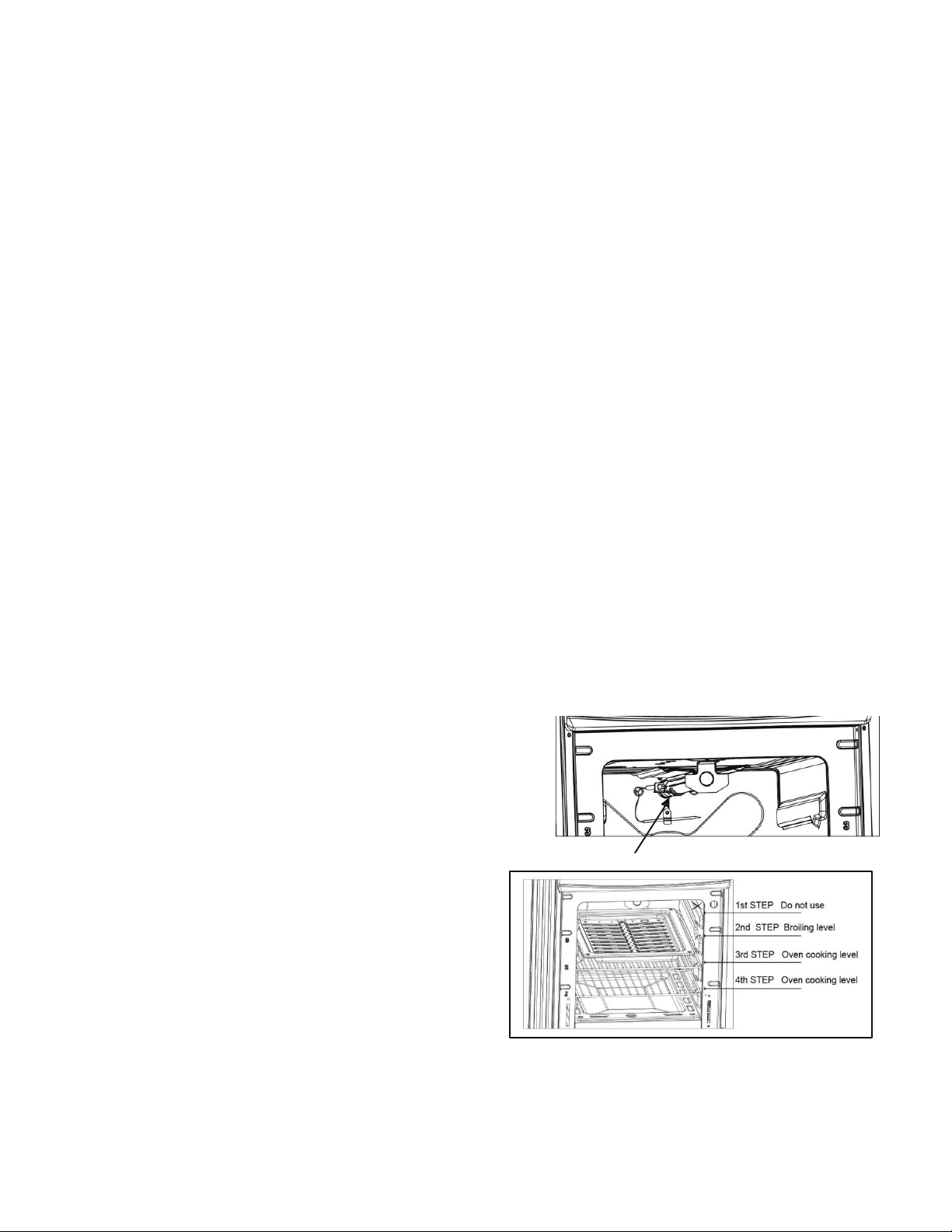
BROILING
Very important: the broil burner must always be used with
the oven door closed.
Position the oven rack on the second level from the top
1. Turn on the broil burner, as explained in the preceding para-
graphs and let the broil burner preheat for about 5 minutes
with the door closed.
2. Place the food to be cooked above the broiling pan.
3. Place the broiling pan in the oven. The broiling pan should
be placed above the shelf and it should be centered with
the broil burner.
OVEN LIGHT
The range is equipped with a light that illuminates the oven to enable visually con-
trolling the food that is cooking. This light is controlled by a button on the left hand
side of the control panel. Simply push the button in to activate the light.
ALIGNMENTS AND ADJUSTMENTS
37
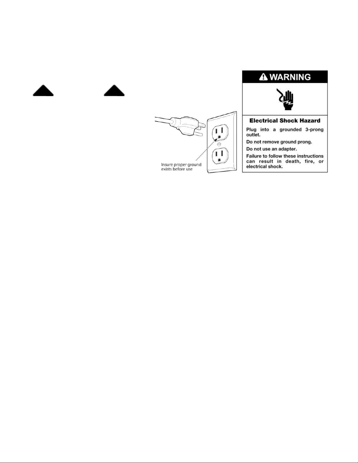
GENERAL RECOMMENDATION
Electrical Shock Hazard
• Plug into a grounded 3-prong
outlet. Insure proper ground
exists before
using the range.
• Do not remove ground prong.
• Do not use an adapter or ex-
tension cord.
• Failure to follow these instructions can result in death, re, or electrical
shock.
Important: Before any operation of cleaning and maintenance disconnect the ap-
pliance from the electrical supply.
It is advisable to clean when the appliance is cold and especially for cleaning the
enameled parts.
Avoid leaving alkaline or acidic substances (lemon juice, vinegar, etc.) on the
surfaces. Avoid using cleaning products with a chlorine or acidic base.
The oven must always be cleaned after every use, using suitable products and
keeping in mind that its operation for 30 minutes on the highest temperature elimi-
nates most grime reducing it to ashes.
Always keep cleaning materials and chemicals in a safe place and away from chil-
dren. Know what you are using. Make sure all parts of the range are COOL before
cleaning. Be sure to replace the parts correctly.
Knobs
Pull forward on the knobs to remove them. Wash in a water solution with a mild
detergentmix.Donotuseanabrasivecleaneroranyabrasiveaction.Abrasiveac-
tion will scratch the knobs.
If the knobs become loose on the valve stem, spread the valve stem slightly with a
small screwdriver.
CLEANING THE RANGE
! !
WARNING

38
Using Commercial Oven Cleaners
Commercial oven cleaners may be used on porcelain lined ovens; however, many
cleaners are very strong, and it’s essential to follow instructions carefully. Be sure to
wear rubber gloves to protect your hands.
After using such cleaners, thoroughly rinse the oven with a solution of 1 tablespoon
vinegar to 1 cup of water. Oven cleaners can coat or damage the thermostat sens-
ing device (the long tube in the oven) so that it will not respond to temperature
accurately. If you use an oven cleaner, do not let it contact the sensing bulb, or any
chrome, aluminum, or plastic part of the range.
Do not apply or allow the cleaner to come in contact with any parts or surfac-
es other than the oven interior.
Grates, Main Tops, Surface Burners
The grates are made of porcelain coated steel. These materials can be cleaned at
thesinkwithdetergentorsoap-lledscouringpads.Donotbealarmedwhenthe
gratelosesitsshinynish.Theheatfromtheburnerswillcausethegratestolose
theirshinynish.
Clean the burner with soap and water, rinse thoroughly and dry completely before
reassembling. Burner heads can be dried in the oven at about 350 degrees Fahren-
heit or in the dishwasher on the dry cycle. After adjustment or cleaning, replace all
parts to their original position.
Stainless Steel Elements
Thestainlesssteelnishtopcanbecleanedwithdetergentandwarmwater.
Stainless steel parts must be rinsed with water and dried with a soft and clean cloth
or with a chamois leather.
Fordifcultgrime,useacommerciallyavailable,non-abrasiveproductforcleaning
stainless steel surfaces, or a little hot vinegar.
Note: regular use could cause discoloring around the burners, because of the high
ametemperature.
Products of combustion from the top pilots as well as certain atmospheric condi-
tions can create an oxidation reaction on the underside of the top. This will appear
as rust or in the form of a reddish brown deposit. This will NOT AFFECT THE LIFE
OF THE TOP in comparison to the general life expectancy of the range itself. It is
very important that the burner be dry before replacing it in the range. A wet burner
will not allow the gas to ignite properly. This could result in a build-up of gas which
couldresultinanexplosionorre.
CLEANING THE RANGE (continued)

Aluminum Foil in Oven
NEVER cover any slots, holes or passages in the oven bottom or
cover an entire rack with materials such as aluminum foil. Doing so
blocks air ow through the oven and may cause carbon monoxide
poisoning. Aluminum foil linings may also trap heat, causing a re
hazard.
Aluminiumfoilwhenusedimproperlyisacauseofmanyrangeres.
Make certain that vents or air openings aren’t covered by the foil. If
the vents located along the sides of the oven bottom are blocked, poor
cooking will result.
Never cover a rack completely. A piece of foil slightly larger than the
cookware can be placed on the rack beneath the cookware.
Remove and discard aluminum foil after each use. This will help prevent
greaseandspilledfoodfromaccumulatingandbecomingarehazard.
Cleaners and Cleaning Materials
Donotuseharshcleanersordegreasersonoraroundfunctionalparts
(valves, controls, etc., or aluminum tubing). This will damage or drasti-
cally reduce the life of the part.
Use only a mild solution of soap and water on backguards, aluminum
control panels and painted surfaces. Never use harsh abrasives or
cleaning powders that may scratch or mar the surface. Make sure the
cleaners and cleaning materials are suitable for use on the area to be
cleaned. Always keep cleaning materials in a safe place. Never use a
sharp metal scraper to clean glass, porcelain, or painted surfaces.
CARE AND MAINTENANCE
! !
WARNING
39

CARE AND MAINTENANCE
(continued)
Repair Parts
When repair parts are needed, contact the dealer from whom the range
was purchased. In case your range was purchased from a source other
than an appliance dealer, you may prefer to contact the manufacturer at
the address shown in this manual.
Moisture
Duringtheinitialheat-upofyourrange,theheatmixingwiththecooler
air in the oven cavity may produce fogging of the door glass or a collec-
tionofwateronthedoor.Topreventthis,opentheovendoorfortherst
few seconds of initial oven heat-up. This will allow the moist air within
the oven to escape, without the forming of visible moisture on the range.
The amount of moisture will depend upon the humidity of the air and wa-
ter content of the food being cooked. Fogging and even dripping water
will usually occur in geographic locations of high humidity.
BURNERS AND CAST-IRON GRIDS
•Thesepartscanberemovedandcleanedwithappropriateproducts.
•Aftercleaning,theburnersandtheiramedistributorsmustbewelldriedand
correctly replaced.
•Itisveryimportanttocheckthattheburneramedistributorandthecaphas
been correctly positioned - failure to do so can cause serious problems.
•Inapplianceswithelectricignitionkeeptheelectrodecleansothatthesparks
always strike.
Note: To avoid damage to the electric ignition do not use it when the
burners are not in place.
40
CARE AND MAINTENANCE
(continued)
CORRECT REPLACEMENT OF THE BURNERS
Itisveryimportanttocheckthattheburnerame
spreader “F” and the cap “C” have been correctly
positioned. Failure to do so can cause serious prob-
lems.In appliances with electric ignition, check that
the electrode “S” is always clean to ensure trouble-
free sparking.
The ignition plug must be cleaned very carefully.
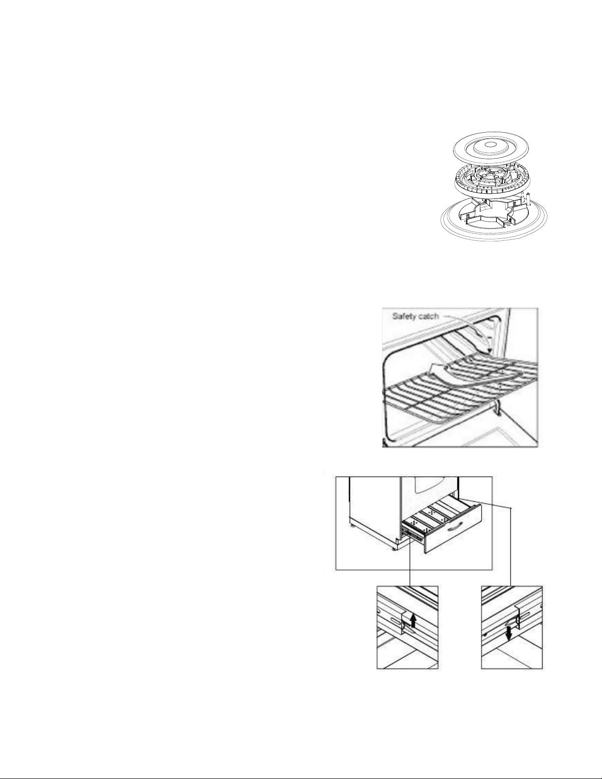
OVEN RACK INSTALLATION AND REMOVAL
•Theovenracksareprovidedwithasafetycatchto
prevent accidental removal.
•Theymustbeinsertedasshown.
•Topullthemoutremovetherackinthe
reverse order.
REMOVABLE STORAGE DRAWER
1. Lift the left small hook upward, at the same time,
push the right small hook downward.(see
the picture )
2. Pull the drawer out.
3. To replace the drawer, align the drawer
with the rails and push inward.
DO NOT STORE FLAMMABLE MATERIAL
IN THE OVEN OR IN THE
BOTTOM DRAWER.
C
F
41
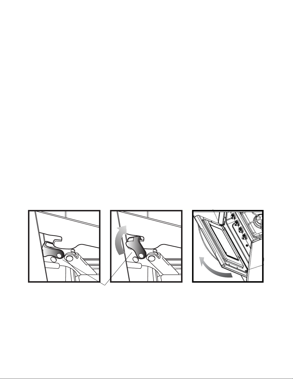
REMOVING THE OVEN DOOR FOR CLEANING
To facilitate oven cleaning, it is possible to remove the door. Please follow the in-
structions carefully:
The oven door can easily be removed as follows:
•Openthedoortofully.
•Lifttheleftandrighthooksonthehingegure(A,B).
•Holdthedoorasshowningure(C).
•Gentlyclosethedoorandliftthedoorwithtwohandswhenthehookstouchthe
door.
•Setthedooronasoftatsurface.
•Toreplacethedoor,repeattheabovestepsinreverseorder.
CARE AND MAINTENANCE
(continued)
hook
(C)(B)(A)
42
CARE AND MAINTENANCE
(continued)
REPLACING THE OVEN LIGHT
•Lettheovencavityandbroilburnercooldown.
•Switchofftheelectricsupply.
•Removetheprotectivecover.
•Unscrewandreplacethebulbwithanewonesuitableforhightemperature
(200°~500°F)havingthesamespecications:120V60Hz,15W,E14.
•Replacetheprotectivecover.
NOTE: Oven bulb replacement is not covered by your guarantee.
LEVELING THE RANGE
The range must be level to obtain proper operating. The four screws type lev-
eling legs located on the corners at the bottom of range should be adjusted by
turning them clockwise to make the range higher or counter-clockwise to lower
the range until the range is level. Use a level on surface units to check the
leveling of the range.
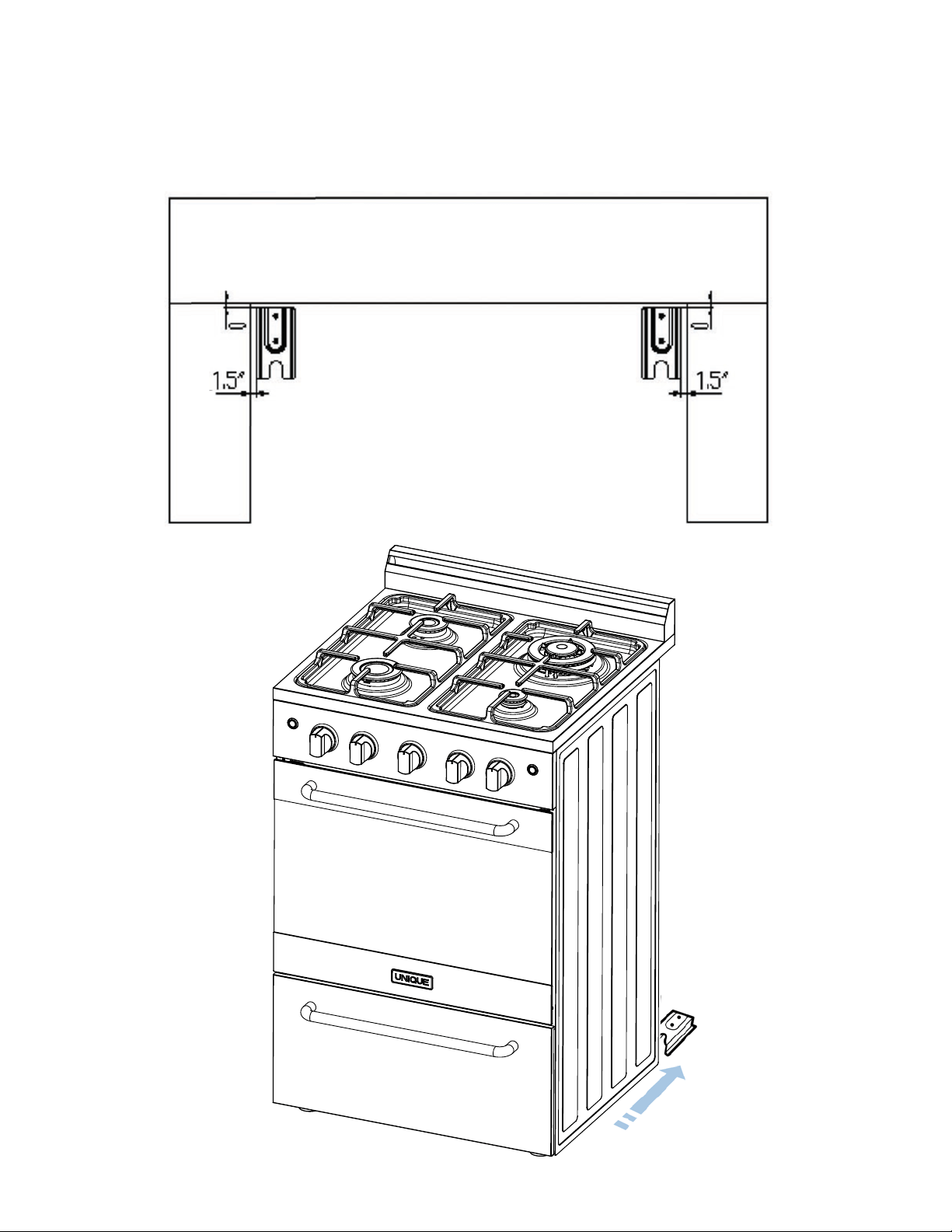
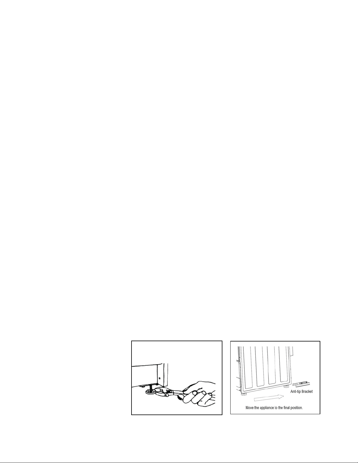
ANTI-TIP BRACKET INSTALLATION
To reduce the risk of tipping the range by abnormal usage or improper door
loading, the range must be secured by properly installing the anti-tip device
packed with the appliance.
•Placetheanti-tipbracketontheoorasshowngure.Anti-tipbracketcanbe
installed on the right and left side.
•Makethelocationsof2(x2)holesofant-tipbracketontheoor.
•Useadrillbit
•Securebrackettooorusingscrewssupplied.
•Slideapplianceintoposition.
NOTE: If range is
relocated, the bracket
must be removed and
installed in new location.
Ø
NOTE: If range is relocated, the bracket must be removed and installed in new location.
43
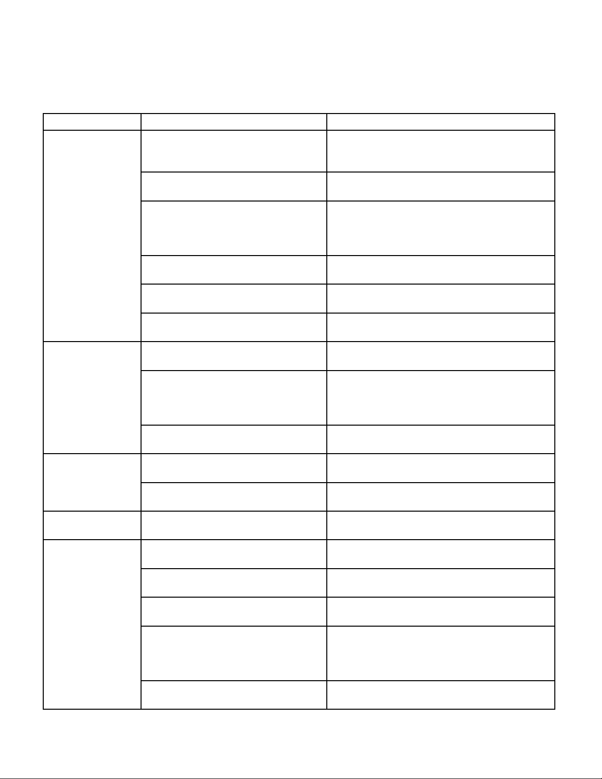
TROUBLESHOOTING
PROBLEM POSSIBLE CAUSE POSSIBLE FIX
Surface burners
do not light.
Surface control has not been com-
pletely turned to the ON position.
Push in and turn control to the ON position
until burner ignites, then turn control to de-
siredamesetting.
Burner ports are clogged. Use a small gauge wire or needle to open
ports.
Burners not positioned properly. Verify that the burners are positioned prop-
erlyontheoricehoodsandtheburnersare
sittingatontheburnersupportwithtabs
engaged in slots.
Range not set for appropriate gas
input.
See range conversion section of installation
manual.
Burners won’t light due to power
failure.
Light burners manually.
Range power cord is disconnected
from the outlet.
Be sure power cord is plugged into grounded
outlet.
Flame burns half-
way round.
Burner ports are clogged. Use a small gauge wire or needle to open
ports.
Moisture is present after cleaning. Lightlyfantheameandallowburnertooper-
ateuntilameisfull.ORdryburnersthor-
oughly following instructions in range “Clean-
ing” section.
Range is not set for appropriate gas
input.
See range conversion section of installation
manual.
Flame is orange.
Dustparticlesinmainline. Allow burner to operate for a few minutes
untilameturnsblue.
Range is not set for appropriate gas
input.
See range conversion section of installation
manual.
Oven light does
not work.
Burned out or loose bulb Tighten or replace oven light bulb.
Oven or broiler
does not heat.
Range is not set for
appropriate gas input.
See range conversion section of installation
manual
Temperature control not set properly. Make sure temperature control is set at de-
sired temperature.
Burners will not light due to power
failure.
Light burners manually.
House fuse has blown or circuit
breaker has tripped.
Check/reset circuit breaker and/or replace
fuse.Donotincreasefusecapacity.Ifthe
problem is a circuit overload, have it corrected
byaqualiedelectrician.
Range cord is disconnected from
outlet.
Be sure the power cord is plugged into a
grounded outlet.
Oven capillary bulb not positioned properly.
Verify that capillary bulb is snapped in clips
straight and not touching sides or coated with oven cleaner or food.
Temperature control not set properly.
Make sure the temperature control knob is set at the desired temperature.
Improper use of foil.
Keep foil clear of holes in oven bottom and o of oven sides.
Vent blocked.
Keep vent on backguard clear.
Range not set for appropriate gas input.
See range conversion section of installation manual.
44
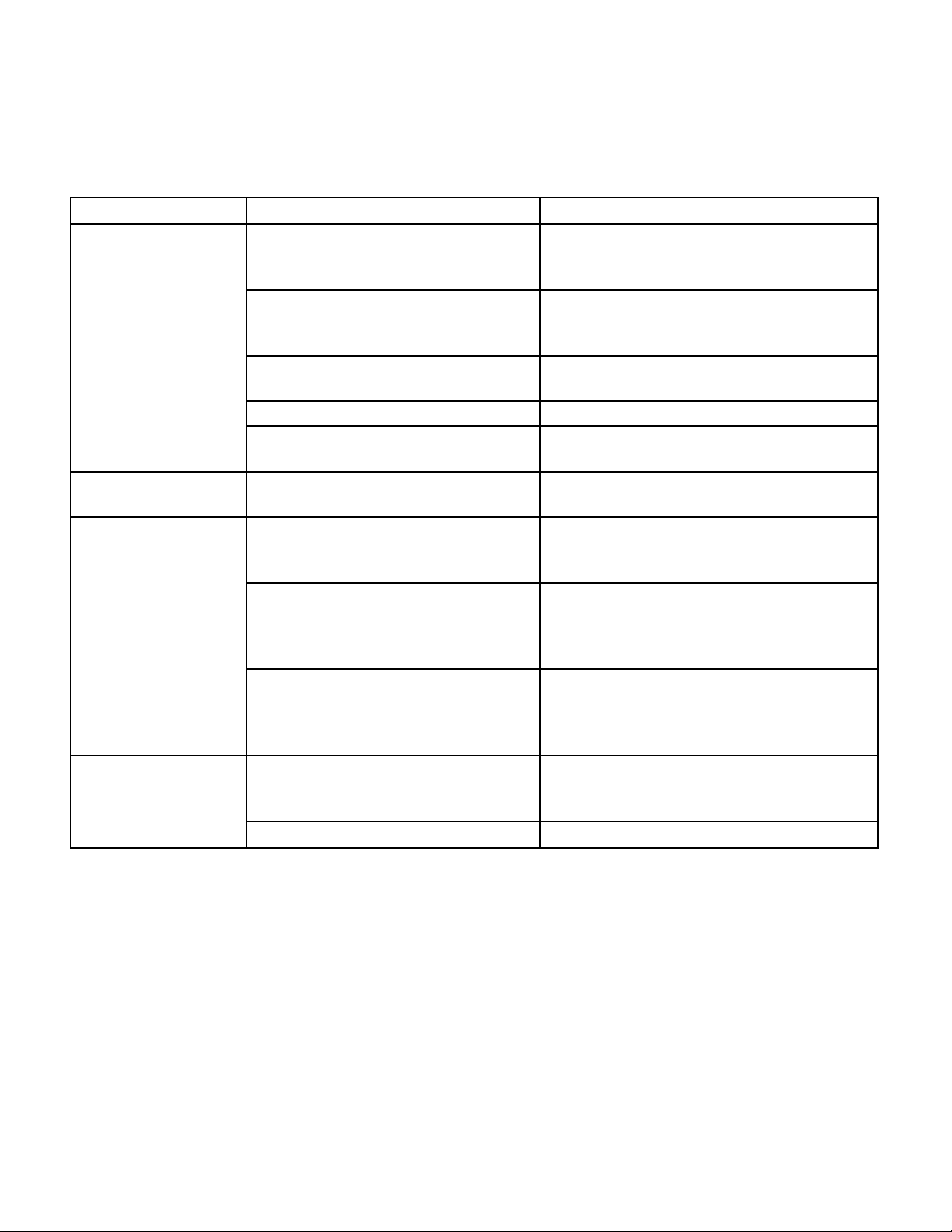
PROBLEM POSSIBLE CAUSE POSSIBLE FIX
Oven temperature is
inaccurate.
Oven capillary bulb not positioned
properly.
Verify that capillary bulb is snapped in clips
straight and not touching sides or coated
with oven cleaner or food.
Temperature control not set properly. Make sure the temperature control knob is
set at the desired temperature.
Improper use of foil. Keep foil clear of holes in oven bottom and
off of oven sides.
Vent blocked. Keep vent on backguard clear.
Range not set for appropriate gas
input.
See range conversion section of installa-
tion manual.
Smoke/odor on ini-
tial oven operation
This is normal
Range is not level Poor installation Place oven rack in centre of oven.
Place a level on the rack. Adjust level-
ing legs.
Weak or unstable floor Be sure floor is level and can ad-
equately support range. Contact car-
penter to correct sagging or sloping
floor.
Kitchen cabinet misalignment
may make range appear to be
unlevel
Be sure cabinets are square and have
sufficient room for range clearance.
Contact cabinet maker to correct prob-
lem.
Oven smokes
excessively
Meat too close to broiler burner Reposition the broiler pan to provide
more clearance between the meat and
the broiler burner.
Meat not prepared properly Remove excess fat from meat.
TROUBLESHOOTING
(continued)
45
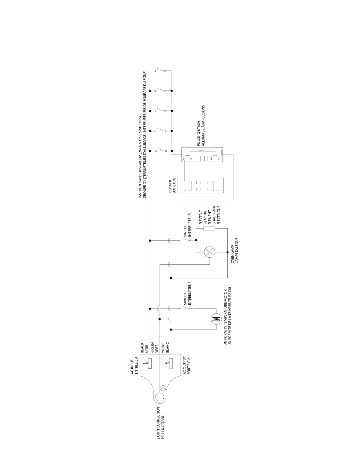
UGP 24V PC1 S/S
WIRING DIAGRAM
46

UNIQUE 24” PRESTIGE GAS RANGE
1 YEAR LIMITED WARRANTY
CONTACT US
Unique Gas Products Ltd., warrants that this 24” Gas Range is free from defects in material and
workmanship under normal usage and service under the following terms:
1.ThisWarrantyismadeonlytotherstpurchaser(“originalpurchaser”)whoacquiresthisrange
for his/her own use and will be honored by Unique Gas Products Ltd. and by the Seller.
2. Any part of this range returned to the Seller or Unique Gas Products Ltd, which upon exami-
nation is determined by them to have been defective in material or workmanship, will at their
option be either repaired or replaced under this warranty, without charge for materials/parts.
3. The obligation to repair or replace defective parts will apply only to parts returned within one
year of the date of purchase and will constitute the Sellers sole obligation under this Warranty.
The Seller will have no obligation under this warranty with respect to conditions unrelated to the
material or workmanship of this range. Such unrelated conditions include without limitation:
a)Damagetoanypartofthisrangecausedbymisuse,neglectofserviceoranyalterationthereof.
b) Use of this product for any purpose other than its Intended use.
This Unique range must be maintained regularly as outlined in the Owner’s Manual. Unique Gas
Products Ltd. and the seller will not be liable for direct or indirect loss of foods caused by failure
in operation. In case of failure, the owner must provide proof of purchase, model, and serial num-
ber to the seller or Unique Gas Products Ltd.
Please ll out warranty card within 30 days and mail back to Unique for warranty coverage.
For general information or questions related to the operation, safety or the
purchase of your range, please contact our customer service department:
•Toll-free:1-877-427-2266or1-905-827-6154(availableduringregularbusiness
hours, 8:30am to 4:30pm, EST.
•Email:[email protected]
Please visit our website for more quality Unique products: www.uniqueoffgrid.com
Unique Gas Products Ltd., 2245 Wyecroft Road #5,
Oakville, Ontario, Canada, L6L 5L7
47
48
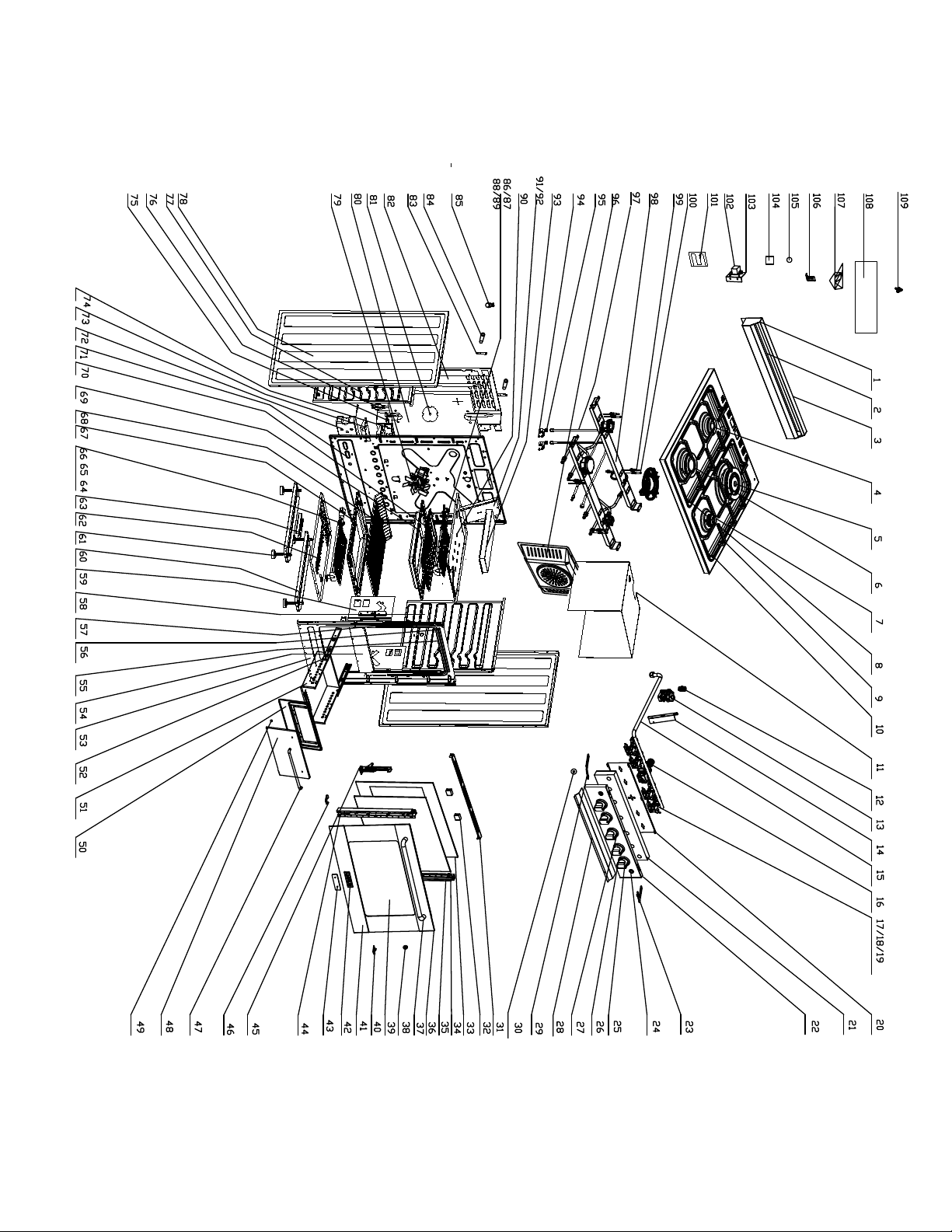
UGP-24V PC1 S/S
PARTS DIAGRAM AND LIST
49
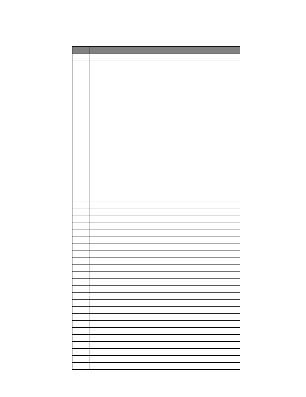
PARTS LIST
Item#
Description Part#
1 Backsplash UGP-G24H08-011600
2 Backsplashinnerplate UGP-G24H08-011700
3 Backsplashcover UGP-G24H08-011500
4 75burner UGP-G20A02-040100
5 130burner UGP-G20A02-040300
6 100burner UGP-G20A02-040200
7 55burner UGP-G20A02-040000
8
Pansupport
(
left
)
UGP-G24C05-021300
9
Pansupport
(
right
)
UGP-G24C05-021600
10 Cooktop UGP-G24H08-020100
11
Cavityheatinsulationplate UGP-C24B01-074500
12 Regulatoradaptor UGP-G24G02-034200
13 Regulator UGP-G20C01-034003
14 Regulatorsupport UGP-G24G02-034500
15 Gaspipe UGP-G24H08-030700
16
Thermostat UGP-G20C02-030619
17
Valve-0.50 UGP-G20D02-030535
18
Valve-0.81 UGP-G20D02-030533
19
Valve-0.95 UGP-G20D02-030534
20 Controlpanelinsidepanel UGP-G24H08-030400
21
Controlpanelinsulationcotton UGP-G24H08-036000
22 Controlpanel UGP-G24H08-030300
23
Controlpanelconnectionplate
(
right
)
UGP-G20C01-022200
24 SwitchASM UGP-G24H08-170200
25 Knob#19 UGP-G20A19-030100-09
26 Knobring#6 UGP-G20A06-030200-10
27 Knob-spring UGP-G20A19-030300
28 Controlpanelstrip UGP-G24H08-214500
29
Controlpanelconnectionplate
(
left
)
UGP-G20C01-022100
30 G1/2gasket UGP-G20A01-210500
31 Doortopcover UGP-G24B01-101401
32 Doorglassshockproof UGP-G20A01-103300
33 LOWEInnerglassdoor UGP-G24H08-100500
34 LOWEDoorinsidewindow UGP-G24H08-101100
35 HingeSupport(right) UGP-G20B01-101300
36 Doorframe(up) UGP-G24H08-020000
37 SUSHandle UGP-G24B11-101900
38 Handlegasket UGP-G20B02-100700
39
Outerdoorglass UGP-G24H08-100400-05
40
Doorinsideglasssupport(right) UGP-G20B01-100900
41 Doorframe(down) UGP-G24H08-020001
42 UniqueLogowithPins UGP-DWWJ03002
43 LOGOgasket UGP-G24F08-100800
44 HingeSupport(left) UGP-G20B01-101200
45 Doorhinge UGP-G20B01-110003
50
PARTS LIST
Item#
Description Part#
46 Doorinsideglasssupport(left) UGP-G20B01-100800
47 SUSHandle UGP-G24B11-101900
48 Draweroutsideplate UGP-G24H08-120100
49 Drawercushiongasket UGP-G20A01-120900
50 Drawerinsideplate UGP-G24C02-120200-04
51 Drawerplate UGP-G24C03-120500-02
52 Slidingrailcomponent UGP-G20A01-120700
53 Frontplate UGP-G24C01-070102
54 Frontplate-Beam UGP-G24A01-070200
55 Frontplateretainingstrip UGP-G24B01-214500
56 Cavitysealingstrip-1 UGP-G24G02-071200
57 Cavitysealingstrip-2 UGP-G24C01-071200
58 Cavityrightplate UGP-G20A01-070500
59 Doorhingeplate UGP-G20C01-111100
60 Ovenfeetmountingplate UGP-G20A01-071100
61 Ovenfeet UGP-G20C01-071500
62 Burnermountingplate UGP-G24C01-072100
63 Anti-tipbracket UGP-G20A01-212500
64 Ovenburnerassembly UGP-G20B01-080100
65 Ovenburnerplate UGP-G20A01-080900
66 Ovenburnersparkplug230 UGP-G20C01-170502
67 Bakeware UGP-G24A01-070700
68 Roastednet UGP-G24H08-071900
69 Broiltray UGP-G20C01-215000
70 Broilgrill UGP-G20C01-215100
71 Backplate UGP-G24C01-070305
72 (2.5Kg)WeightBlock UGP-G20A01-210200
73 Regulatorfixedpart UGP-G20C01-034500
74 120VIgnitor UGP-G20C01-170106
75 Powerfixedparts UGP-G20A01-160200
76 (18AWG)PowerCord UGP-G20A07-160105
77 Cavityleftplate UGP-G20A01-070400
78 T=0.5Sideplate UGP-G20C01-071002
79 120VTemperaturefan UGP-G20A01-091502
80 Backinsulationcotton UGP-G24C01-072900
81 Temperaturefanbaffle UGP-C36A01-073100
82 Baffleplate UGP-G24C01-072000
83 cooktopbackconnectionplate UGP-G20C01-022000
84 Supportbetweenwallandunit UGP-G20C01-212600
85 120V15WLamp UGP-G20C01-180101
86 Topburnerassembly UGP-G20C01-090100
87 Topburnerplate UGP-G20C01-090300
88 Topburnerinfrarednetwork UGP-G20C01-090500
89 Grillburnersparkplug540 UGP-G20C01-170500
90 Cavitytopplate UGP-G24C01-070600
51
PARTS LIST
Item#
Description Part#
91 Chimney(withhole) UGP-G20C01-074101
92 Chimney(nohole) UGP-G20C01-074100
93 DiversionPlate UGP-G20C01-075000
NGInjector(0.73) UGP-G20A01-021208
LPGInjector(0.53) UGP-G20A01-021200
NGInjector(1.0) UGP-G20A01-021206
LPGInjector(0.68) UGP-G20A01-021201
NGInjector(1.3) UGP-G20A01-021213
LPGInjector(0.9) UGP-G20A01-021203
NGInjector(1.5) UGP-G20A01-021227
LPGInjector(1.0) UGP-G20A01-021206
TopburnerNGinjector(1.24) UGP-G20A01-021212
TopburnerLPGinjector(0.8) UGP-G20A01-021202
OvenburnerNGinjector(1.3) UGP-G20A01-021213
OvenburnerLPGinjector(0.82) UGP-G20A01-021204
95 Nozzlemountpart UGP-G20A01-021100
96 Temperaturefancover UGP-G36A01-091700
left/backpipeassembly UGP-G24H08-022300
right/backpipeassembly UGP-G24H08-022600
left/frontright/frontpipeassembly UGP-G24F08-022500
Ovenburnerasm-burnerpipe UGP-G20C01-023100
Topburnerasm-burnerpipe UGP-G20C01-023300
98 burnercupmountingplate UGP-G24C01-024200
Sparkplug1100 UGP-G24A01-170401
Sparkplug1050 UGP-G20A01-170406
Sparkplug900 UGP-G20A01-170405
Sparkplug680 UGP-G20A01-170404
Thermocouple300mm UGP-G20A01-030900
Thermocouple500mm UGP-G20A01-030901
Thermocouple UGP-G24A01-031000
101 AluminumfoilCeramicHeater UGP-G20A01-300500
102 Transformer UGP-G20A01-106600
103 Transformerfixedplate UGP-G24C01-191000
104 Sparkplug-retainer UGP-G20A01-170600
105 Wireconectors UGP-G20A01-160300
106 Doorglasssupport UGP-G20A10-100900
107 Harness UGP-G24H08-180300
108 Cavityheatinsulationcotton UGP-G24A01-070800
109 Thermostatproberetainingclip UGP-G20A01-031100
94
97
99
100
APPLIANCE INFORMATION
(manual copy - keep with your records)
APPLIANCE INFORMATION
(remote copy - keep with your appliance)
detatch along dotted line detatch along dotted line
detatch along dotted line detatch along dotted line
T
omakecareandservicingofyourrangeeasyandefcient,pleaserecordthefollowing
information for future reference:
Model:
Serial Number:
Purchased From:
DatePurchased:
Installed By:
Tomakecareandservicingofyourrangeeasyandefcient,pleaserecordthefollowing
information for future reference:
Model:
Serial Number:
Purchased From:
DatePurchased:
Installed By:
52

NOTES
53

© 2017 Unique Gas Products Ltd., 2245 Wyecroft Road #5, Oakville, Ontario, Canada, L6L 5L7
www.uniqueoffgrid.com