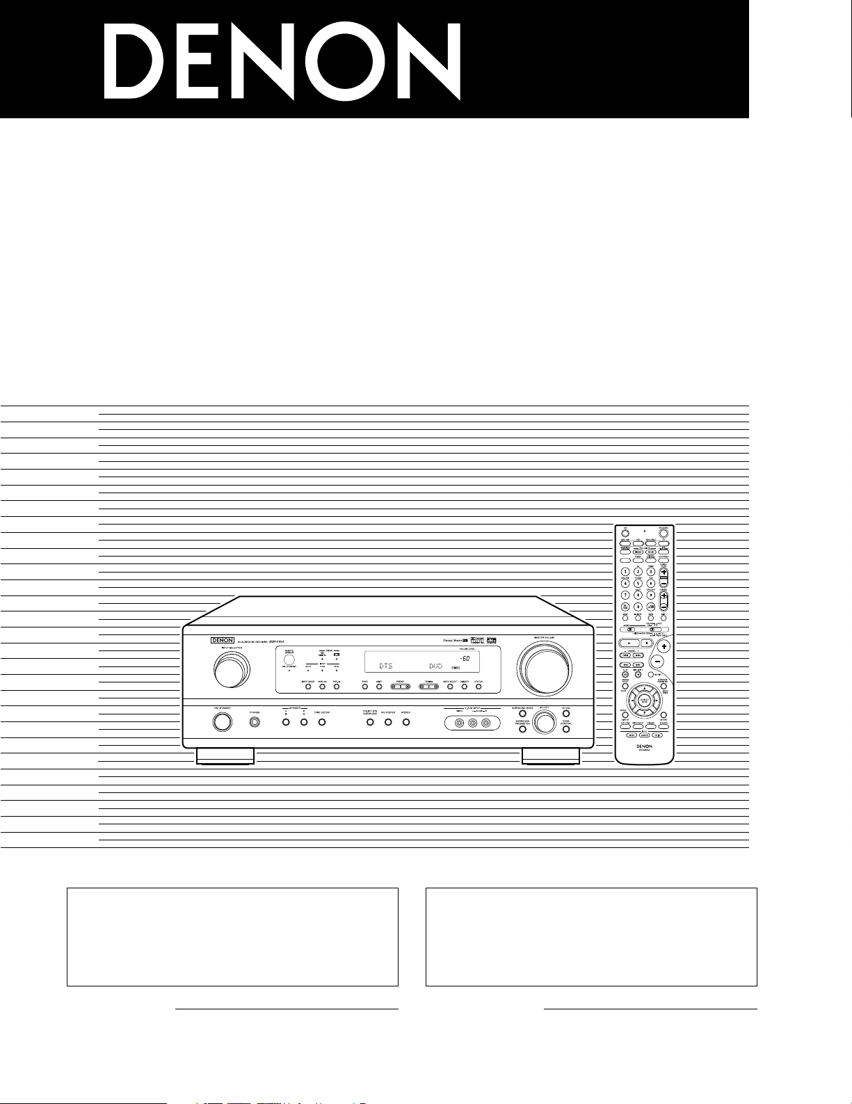
AV SURROUND RECEIVER
AVR-1404/484
OPERATING INSTRUCTIONS
MODE D’EMPLOI
2
We greatly appreciate your purchase of this unit.
2
To be sure you take maximum advantage of all the
features this unit has to offer, read these instructions
carefully and use the set properly. Be sure to keep this
manual for future reference should any questions or
problems arise.
“SERIAL NO.
PLEASE RECORD UNIT SERIAL NUMBER ATTACHED TO
THE REAR OF THE CABINET FOR FUTURE REFERENCE”
“NO. DE SERIE
PRIERE DE NOTER LE NUMERO DE SERIE DE L’APPAREIL
INSCRIT A L’ARRIERE DU COFFRET DE FAÇON A POUVOIR
LE CONSULTER EN CAS DE PROBLEME.”
2
Nous vous remercions pour l’achat de cet appareil.
2
Pour être sûr de profiter au maximum de toutes les
caractéristiques qu’offre cet appareil, lire avec soin ces
instructions et bien utiliser l’appareil. Toujours
conserver ce mode d’emploi pour s’y référer
ultérieurement en cas de question ou de problème.
FOR ENGLISH READERS PAGE 2 ~ PAGE 50, 98 ~ 102 POUR LES LECTEURS FRANCAIS PAGE 2, 51 ~ PAGE 102
2
ENGLISH
2 SAFETY PRECAUTIONS
2 NOTE ON USE / OBSERVATIONS RELATIVES A L’UTILISATION
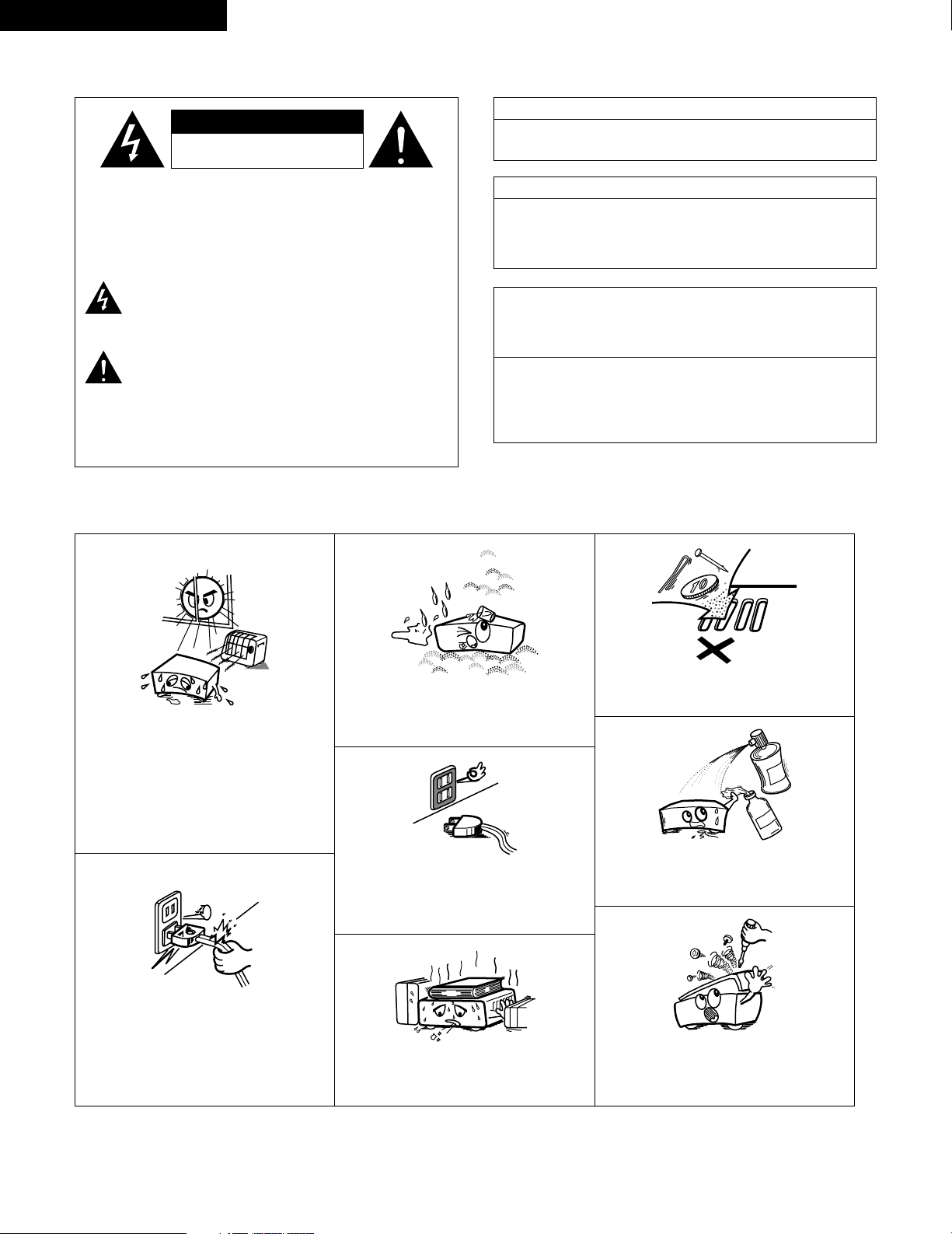
• Avoid high temperatures.
Allow for sufficient heat dispersion when
installed on a rack.
• Eviter des températures élevées.
Tenir compte d’une dispersion de chaleur
suffisante lors de l’installation sur une étagère.
• Handle the power cord carefully.
Hold the plug when unplugging the cord.
• Manipuler le cordon d’alimentation avec
précaution.
Tenir la prise lors du débranchement du
cordon.
• Keep the set free from moisture, water, and
dust.
• Protéger l’appareil contre l’humidité, l’eau et la
poussière.
• Unplug the power cord when not using the set
for long periods of time.
• Débrancher le cordon d’alimentation lorsque
l’appareil n’est pas utilisé pendant de longues
périodes.
* (For sets with ventilation holes)
• Do not obstruct the ventilation holes.
• Ne pas obstruer les trous d’aération.
• Do not let foreign objects in the set.
• Ne pas laisser des objets étrangers dans
l’appareil.
• Do not let insecticides, benzene, and thinner
come in contact with the set.
• Ne pas mettre en contact des insecticides, du
benzène et un diluant avec l’appareil.
• Never disassemble or modify the set in any
way.
• Ne jamais démonter ou modifier l’appareil
d’une manière ou d’une autre.
CAUTION
RISK OF ELECTRIC SHOCK
DO NOT OPEN
CAUTION: TO REDUCE THE RISK OF ELECTRIC SHOCK,
DO NOT REMOVE COVER (OR BACK). NO
USER-SERVICEABLE PARTS INSIDE. REFER
SERVICING TO QUALIFIED SERVICE
PERSONNEL.
The lightning flash with arrowhead symbol, within an
equilateral triangle, is intended to alert the user to the
presence of uninsulated “dangerous voltage” within the
product’s enclosure that may be of sufficient magnitude to
constitute a risk of electric shock to persons.
The exclamation point within an equilateral triangle is intended
to alert the user to the presence of important operating and
maintenance (servicing) instructions in the literature
accompanying the appliance.
WARNING:
TO REDUCE THE RISK OF FIRE OR ELECTRIC
SHOCK, DO NOT EXPOSE THIS APPLIANCE
TO RAIN OR MOISTURE.
CAUTION
TO PREVENT ELECTRIC SHOCK, MATCH WIDE BLADE OF PLUG
TO WIDE SLOT, FULLY INSERT.
ATTENTION
POUR ÉVITER LES CHOCS ÉLECTRIQUES, INTERODUIRE LA
LAME LA PLUS LARGE DE LA FICHE DANS LA BORNE
CORRESPONDANTE DE LA PRISE ET POUSSER JUSQU’ AU
FOND.
This device complies with Part 15 of the FCC Rules. Operation is subject to
the following two conditions: (1) This device may not cause harmful
interference, and (2) this device must accept any interference received,
including interference that may cause undesired operation.
This Class B digital apparatus meets all requirements of the Canadian
Interference-Causing Equipment Regulations.
Cet appareil numérique de la classe B respecte toutes les exigences du
Règlement sur le matériel brouilleur du Canada.
FRANCAIS

3
SAFETY INSTRUCTIONS
1. Read Instructions – All the safety and operating instructions
should be read before the product is operated.
2. Retain Instructions – The safety and operating instructions
should be retained for future reference.
3. Heed Warnings – All warnings on the product and in the
operating instructions should be adhered to.
4. Follow Instructions – All operating and use instructions should
be followed.
5. Cleaning – Unplug this product from the wall outlet before
cleaning. Do not use liquid cleaners or aerosol cleaners.
6. Attachments – Do not use attachments not recommended by
the product manufacturer as they may cause hazards.
7. Water and Moisture – Do not use this product near water – for
example, near a bath tub, wash bowl, kitchen sink, or laundry
tub; in a wet basement; or near a swimming pool; and the like.
8. Accessories – Do not place this product on an unstable cart,
stand, tripod, bracket, or table. The product may fall, causing
serious injury to a child or adult, and serious damage to the
product. Use only with a cart, stand, tripod, bracket, or table
recommended by the manufacturer, or sold with the product.
Any mounting of the product should follow the manufacturer’s
instructions, and should use a
mounting accessory
recommended by the
manufacturer.
9. A product and cart
combination should be
moved with care. Quick
stops, excessive force,
and uneven surfaces may
cause the product and cart
combination to overturn.
10. Ventilation – Slots and openings in the cabinet are provided for
ventilation and to ensure reliable operation of the product and to
protect it from overheating, and these openings must not be
blocked or covered. The openings should never be blocked by
placing the product on a bed, sofa, rug, or other similar surface.
This product should not be placed in a built-in installation such
as a bookcase or rack unless proper ventilation is provided or
the manufacturer’s instructions have been adhered to.
11. Power Sources – This product should be operated only from the
type of power source indicated on the marking label. If you are
not sure of the type of power supply to your home, consult your
product dealer or local power company. For products intended
to operate from battery power, or other sources, refer to the
operating instructions.
12. Grounding or Polarization – This product may be equipped with
a polarized alternating-current line plug (a plug having one blade
wider than the other). This plug will fit into the power outlet
only one way. This is a safety feature. If you are unable to
insert the plug fully into the outlet, try reversing the plug. If the
plug should still fail to fit, contact your electrician to replace your
obsolete outlet. Do not defeat the safety purpose of the
polarized plug.
13. Power-Cord Protection – Power-supply cords should be routed
so that they are not likely to be walked on or pinched by items
placed upon or against them, paying particular attention to
cords at plugs, convenience receptacles, and the point where
they exit from the product.
15. Outdoor Antenna Grounding – If an outside antenna or cable
system is connected to the product, be sure the antenna or
cable system is grounded so as to provide some protection
against voltage surges and built-up static charges. Article 810
of the National Electrical Code, ANSI/NFPA 70, provides
information with regard to proper grounding of the mast and
supporting structure, grounding of the lead-in wire to an
antenna discharge unit, size of grounding conductors, location
of antenna-discharge unit, connection to grounding electrodes,
and requirements for the grounding electrode. See Figure A.
16. Lightning – For added protection for this product during a
lightning storm, or when it is left unattended and unused for
long periods of time, unplug it from the wall outlet and
disconnect the antenna or cable system. This will prevent
damage to the product due to lightning and power-line surges.
17. Power Lines – An outside antenna system should not be
located in the vicinity of overhead power lines or other electric
light or power circuits, or where it can fall into such power lines
or circuits. When installing an outside antenna system,
extreme care should be taken to keep from touching such
power lines or circuits as contact with them might be fatal.
18. Overloading – Do not overload wall outlets, extension cords, or
integral convenience receptacles as this can result in a risk of
fire or electric shock.
19. Object and Liquid Entry – Never push objects of any kind into
this product through openings as they may touch dangerous
voltage points or short-out parts that could result in a fire or
electric shock. Never spill liquid of any kind on the product.
20.
Servicing – Do not attempt to service this product yourself as
opening or removing covers may expose you to dangerous
voltage or other hazards. Refer all servicing to qualified
service personnel.
21.
Damage Requiring Service – Unplug this product from the
wall outlet and refer servicing to qualified service
personnel
under the following conditions:
a) When the power-supply cord or plug is damaged,
b) If liquid has been spilled, or objects have fallen into the
product,
c) If the product has been exposed to rain or water,
d) If the product does not operate normally by following the
operating instructions. Adjust only those controls that are
covered by the operating instructions as an improper
adjustment of other controls may result in damage and will
often require extensive work by a qualified technician to
restore the product to its normal operation,
e) If the product has been dropped or damaged in any way, and
f) When the product exhibits a distinct change in performance
– this indicates a need for service.
22. Replacement Parts – When replacement parts are required, be
sure the service technician has used replacement parts
specified by the manufacturer or have the same characteristics
as the original part. Unauthorized substitutions may result in
fire, electric shock, or other hazards.
23. Safety Check – Upon completion of any service or repairs to this
product, ask the service technician to perform safety checks to
determine that the product is in proper operating condition.
24. Wall or Ceiling Mounting – The product should be mounted to a
wall or ceiling only as recommended by the manufacturer.
25. Heat – The product should be situated away from heat sources
such as radiators, heat registers, stoves, or other products
(including amplifiers) that produce heat.
FIGURE A
EXAMPLE OF ANTENNA GROUNDING
AS PER NATIONAL
ELECTRICAL CODE
ANTENNA
LEAD IN
WIRE
GROUND
CLAMP
ELECTRIC
SERVICE
EQUIPMENT
ANTENNA
DISCHARGE UNIT
(NEC SECTION 810-20)
GROUNDING CONDUCTORS
(NEC SECTION 810-21)
GROUND CLAMPS
POWER SERVICE GROUNDING
ELECTRODE SYSTEM
(NEC ART 250, PART H)
NEC - NATIONAL ELECTRICAL CODE
4
ENGLISH
2 INTRODUCTION
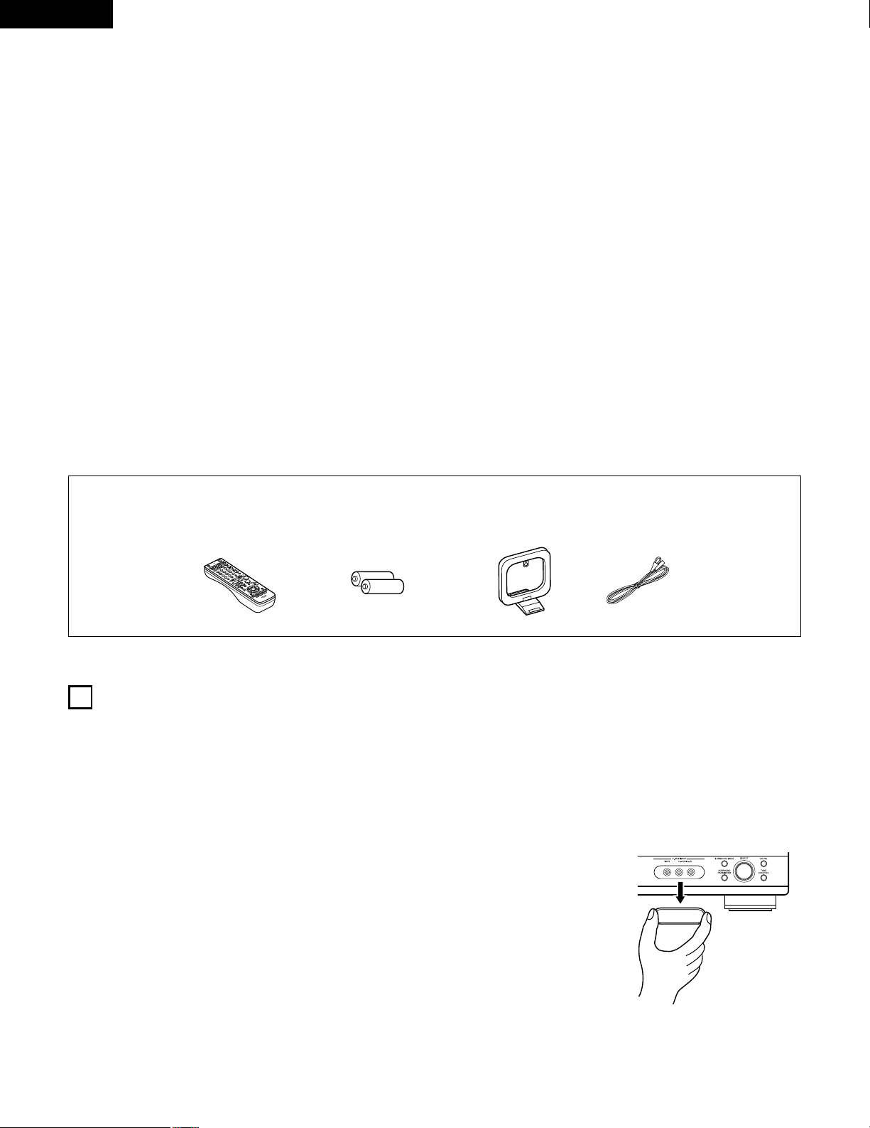
2 ACCESSORIES
Thank you for choosing the DENON A/V Surround receiver. This remarkable component has been engineered to provide superb surround sound
listening with home theater sources such as DVD, as well as providing outstanding high fidelity reproduction of your favorite music sources.
As this product is provided with an immense array of features, we recommend that before you begin hookup and operation that you review the
contents of this manual before proceeding.
TABLE OF CONTENTS
Check that the following parts are included in addition to the main unit:
1
BEFORE USING
Pay attention to the following before using this unit:
• Moving the set
To prevent short circuits or damaged wires in the connection cords,
always unplug the power cord and disconnect the connection
cords between all other audio components when moving the set.
• Before turning the power operation switch on
Check once again that all connections are proper and that there are
not problems with the connection cords. Always set the power
operation switch to the standby position before connecting and
disconnecting connection cords.
• Store this instructions in a safe place.
After reading, store this instructions along with the warranty in a
safe place.
• Note that the illustrations in this instructions may differ from
the actual set for explanation purposes.
• V. AUX terminal
The AVR-1404/484’s front
panel is equipped with a V.
AUX terminal. Remove the
cap covering the terminal
when you want to use it.
z
Before Using ..............................................................................................4
x
Cautions on Installation ..............................................................................5
c
Cautions on Handling .................................................................................5
v
Features......................................................................................................5
b
Part Names and Functions.....................................................................6, 7
n
Read this first .............................................................................................8
m
Setting up the Speaker Systems................................................................8
,
Connections .........................................................................................9~14
.
Using the Remote Control Unit................................................................15
⁄0
Setting up the System .......................................................................16~20
⁄1
Remote Control Unit..........................................................................21~25
⁄2
Operation ...........................................................................................26~30
⁄3
Surround.............................................................................................31~36
⁄4
DSP Surround Simulation...................................................................37~41
⁄5
Listening to the Radio……………………………………………………42~44
⁄6
Last Function Memory .............................................................................45
⁄7
Initialization of the Microprocessor.…………………………………………45
⁄8
Additional Information........................................................................46~48
⁄9
Troubleshooting ........................................................................................49
¤0
Specifications .…………………………………………………………………50
List of Preset Codes................................................................................98~102
q Operating instructions ............................................................................1
w Warranty .................................................................................................1
e Service station list...................................................................................1
r Remote control unit (RC-942).................................................................1
rt y u
t R6P/AA batteries ....................................................................................2
y AM loop antenna ....................................................................................1
u FM indoor antenna..................................................................................1
5
ENGLISH
3
CAUTIONS ON HANDLING
4
FEATURES
• Switching the input function when input jacks are not
connected
A clicking noise may be produced if the input function is switched
when nothing is connected to the input jacks. If this happens,
either turn down the MASTER VOLUME control or connect
components to the input jacks.
• Muting of PRE OUT jack, HEADPHONE jack and SPEAKER
terminals
The PRE OUT jack, HEADPHONE jack and SPEAKER terminals
include a muting circuit. Because of this, the output signals are
greatly reduced for several seconds after the power operation
switch is turned on or input function, surround mode or any other
set-up is changed.
If the volume is turned up during this time, the output will be very
high after the muting circuit stops functioning. Always wait until
the muting circuit turns off before adjusting the volume.
• Whenever the power operation switch is in the STANDBY
state, the apparatus is still connected on some AC line
voltages.
Please be sure to unplug the cord when you leave home for,
say, a vacation.
1. Dolby Pro Logic II decoder
Dolby Pro Logic II is a new format for playing multichannel audio
signals that offers improvements over conventional Dolby Pro
Logic. It can be used to decode not only sources recorded in
Dolby Surround but also regular stereo sources into five channels
(front left/right, center and surround left/right). In addition, various
parameters can be set according to the type of source and the
contents, so you can adjust the sound field with greater precision.
2. Dolby Digital decoder
Dolby Digital, a digital discrete system in which the different
channels are completely independent, recreates “three-
dimensional” sound fields (sounds with a sense of distance,
movement and position) with no crosstalk between channels for
greater reality. In addition, the 5 channels (excluding the 0.1
channel for low frequency effects) have a playback range
extending to 20 kHz, the same as the range of CDs, thus resulting
in clearer, more richly expressive sound.
3. DTS (Digital Theater Systems)
DTS provides up to 5.1 channels of wide-range, high fidelity
surround sound, from sources such as laser disc, DVD and
specially-encoded music discs.
4. High performance DSP simulates 7 sound fields
Playback is possible in 7 surround modes: 5-channel Stereo, Mono
Movie, Rock Arena, Jazz Club, Video Game, Matrix and Virtual.
You can enjoy a variety of sound effects for different movie
scenes and program sources even with stereo sources not in
Dolby Surround.
5. Personal Memory Plus function
Personal Memory Plus is an advanced version of Personal
Memory. With Personal Memory Plus, the set automatically
memorizes the surround mode, channel volume, surround
parameters, etc., for each of the separate input sources.
6. Remote control unit with pre-memory function
This unit comes with a remote control unit equipped with a pre-
memory function. The remote control command codes for
DENON remote controllable AV components as well as for LD
players, video decks, TVs, etc., of other major manufacturers are
prestored in the memory.
7. 6CH EXT. IN jacks
This unit is equipped with 6CH EXT. IN jacks for use with audio
formats of the future.
2
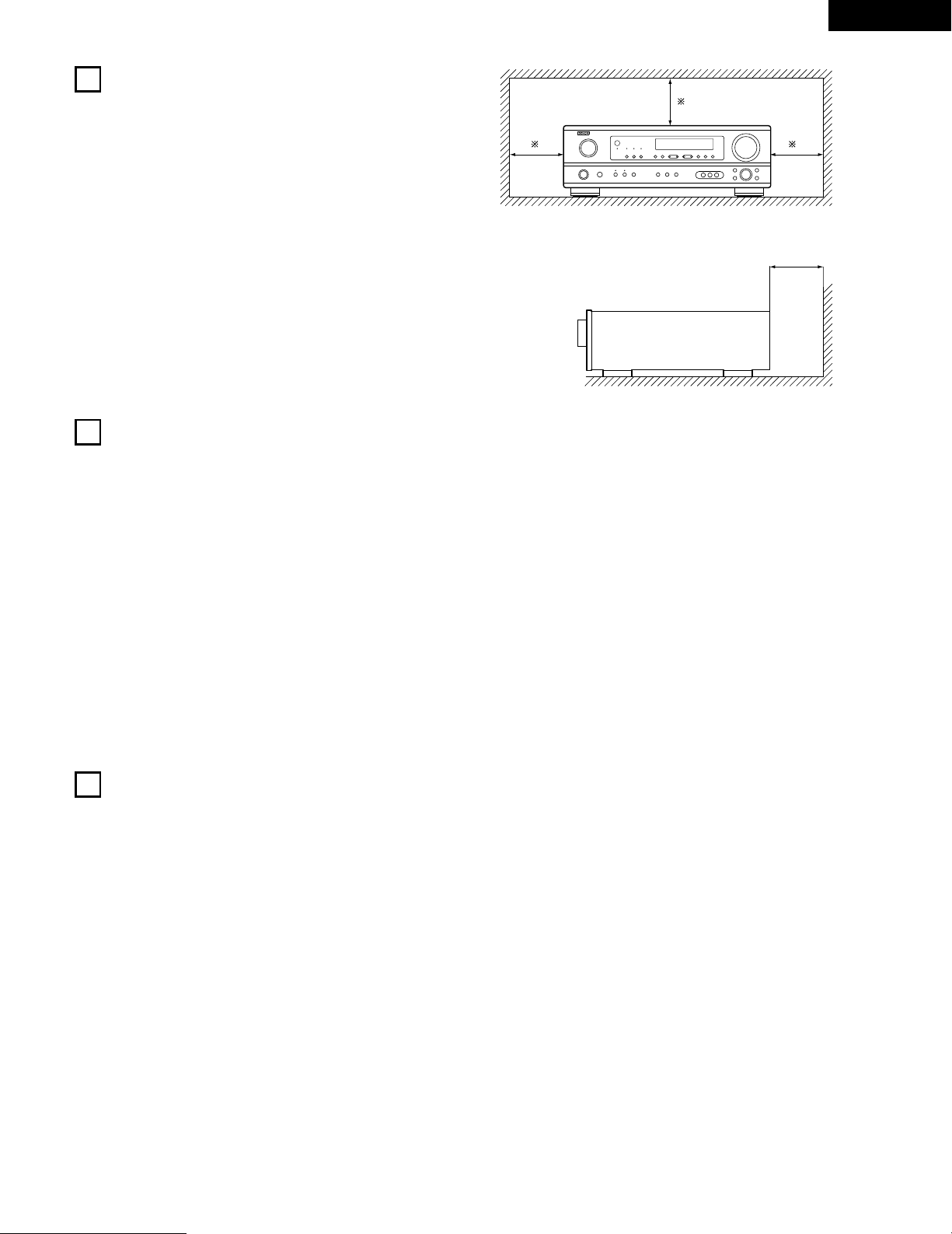
CAUTIONS ON INSTALLATION
Noise or disturbance of the picture may be generated if this unit or
any other electronic equipment using microprocessors is used near a
tuner or TV.
If this happens, take the following steps:
• Install this unit as far as possible from the tuner or TV.
• Set the antenna wires from the tuner or TV away from this unit’s
power cord and input/output connection cords.
• Noise or disturbance tends to occur particularly when using indoor
antennas or 300 Ω/ohms feeder wires. We recommend using
outdoor antennas and 75 Ω/ohms coaxial cables.
For heat dispersal, leave at least 0.3 ft (10 cm) of space between
the top, back and sides of this unit and the wall or other
components.
0.3 ft (10 cm) or more
wall
0.3 ft (10 cm) or more
6
ENGLISH
5
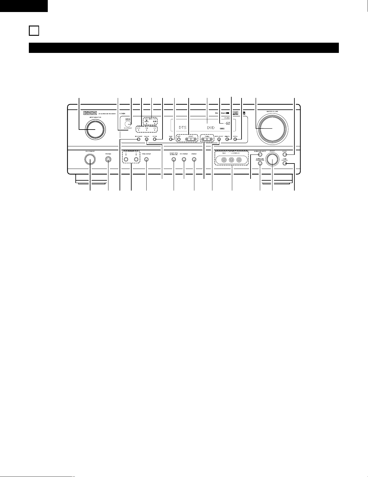
PART NAMES AND FUNCTIONS
Front Panel
• For details on the functions of these parts, refer to the pages given in parentheses ( ).
q w te ur
y i!3!0
@0@1
@2@3@4@5
@6
@7@8@9
!1 !2 !4 !5 !6o
!7!9 !8#0
q
Power operation switch ..............................................(17, 26, 42)
w
Headphones jack (PHONES)....................................................(29)
e
INPUT MODE button.........................................................(27, 30)
r
SPEAKER A/B buttons.................................................(26, 29, 45)
t
TONE DEFEAT button ............................................................(28)
y
ANALOG button ................................................................(27, 30)
u
DOLBY/DTS SURROUND button ......................................(33, 35)
i
5CH STEREO button ..............................................................(37)
o
STEREO button........................................................................(37)
!0
TUNING D (up) / H (down) buttons.........................................(43)
!1
VIDEO SELECT button ............................................................(29)
!2
V. AUX terminals..................................................................(4, 11)
!3
SURROUND MODE button...............................................(28, 40)
!4
SURROUND PARAMETER button.....................................(33, 38)
!5
SELECT knob.........................................................(28, 32, 33, 40)
!6
TONE CONTROL button..........................................................(28)
!7
CH VOL button ........................................................................(32)
!8
MASTER VOLUME control......................................................(28)
!9
STATUS button ........................................................................(29)
@0
DIMMER button ......................................................................(29)
@1
Master volume indicator (VOLUME LEVEL)............................(28)
@2
Display
@3
Preset station select buttons ............................................(42, 44)
@4
BAND button ...........................................................................(43)
@5
EXT. IN button ...................................................................(27, 30)
@6
SIGNAL indicators....................................................................(28)
@7
INPUT mode indicators............................................................(28)
@8
Remote control sensor (REMOTE SENSOR) ..........................(15)
@9
Power operation indicator (ON/STANDBY)
#0
INPUT SELECTOR knob ..........................................................(27)
7
ENGLISH
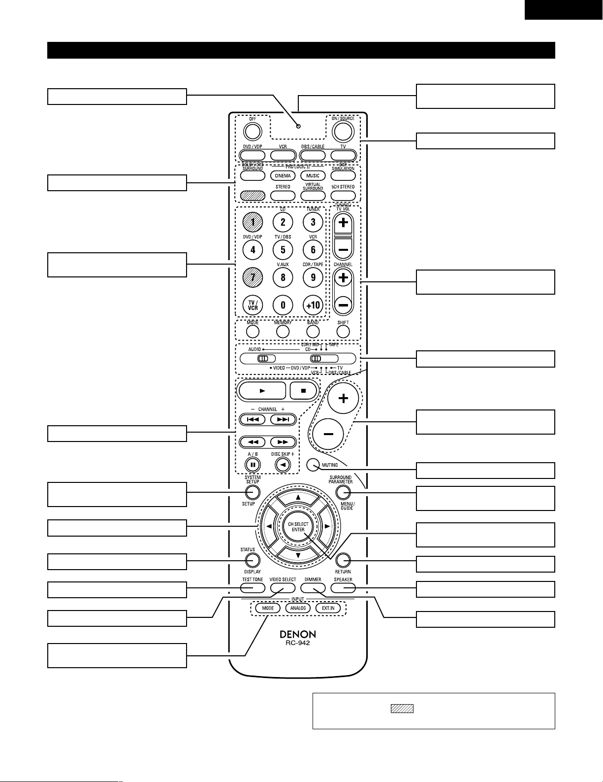
Remote control unit
• For details on the functions of these parts, refer to the pages given in parentheses ( ).
SURROUND buttons .............(28, 33, 38)
Cursor buttons...........(16, 23, 31~33, 35)
STATUS/DISPLAY button .............(23, 29)
Test tone button.................................(31)
Remote control signal
transmitter .........................................(15)
Master volume control
buttons...............................................(28)
POWER buttons ....................(17, 22~26)
MUTING button .................................(29)
Mode selector switches..(16, 21~23, 25)
Tuner system/
System buttons .....................(21, 43, 44)
SYSTEM SET UP/
SETUP button ..............................(16, 23)
INPUT MODE selector
buttons.........................................(27, 30)
Input source selector
buttons ..................................(22~25, 27)
SURROUND PARAMETER
button ....................................(23, 33, 38)
CH SELECT (channel select)/
ENTER button ..............................(16, 32)
RETURN button .................................(23)
SPEAKER select button .....................(26)
DIMMER button.................................(29)
VIDEO SELECT button.......................(29)
System buttons ...........................(21, 23)
LED (indicator) .............................(22, 25)
NOTE:
• The shaded buttons do not function with the AVR-1404/484.
(Nothing happens when they are pressed.)
8
ENGLISH
6
READ THIS FIRST
This AV Surround Receiver must be setup before use. Following these steps.
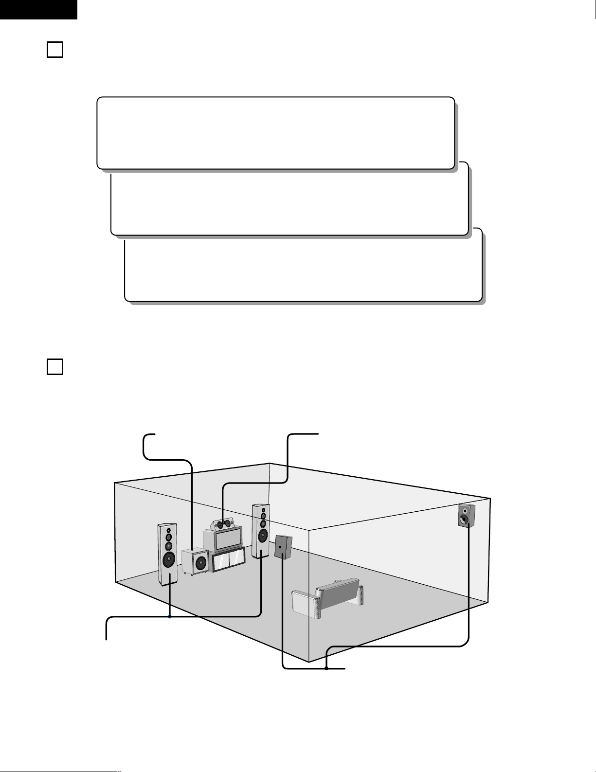
2 Speaker system layout
Basic system layout
• The following is an example of the basic layout for a system consisting of six speaker systems and a television monitor:
Subwoofer Center speaker system
Surround speaker systems
Front speaker systems
Set these at the sides of the TV or screen with
their front surfaces as flush with the front of the
screen as possible.
7
SETTING UP THE SPEAKER SYSTEMS
Step 3 (page 16 to 20)
Finally, setting up the system.
Step 2 (page 15)
Next, insert the batteries into the remote control unit.
Step 1 (page 8 to 14)
Choose the best location to setup the Speakers and connecting the components.
9
ENGLISH
8
CONNECTIONS
• Do not plug in the power cord until all connections have been
completed.
• Be sure to connect the left and right channels properly (left with
left, right with right).
• Insert the plugs securely. Incomplete connections will result in
the generation of noise.
• Use the AC OUTLET for audio equipment only. Do not use
them for hair driers, etc.
• Note that binding pin plug cords together with power cords or
placing them near a power transformer will result in generating
hum or other noise.
• Noise or humming may be generated if a connected audio
equipment is used independently without turning the power
of this unit on. If this happens, turn on the power of the this
unit.
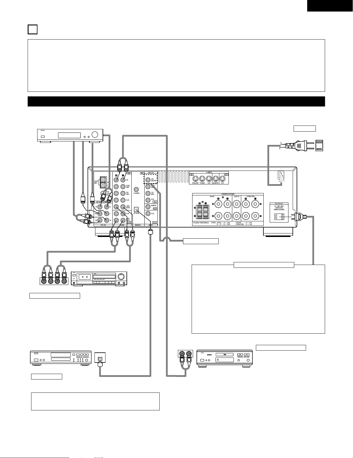
Connecting the audio components
LINE OUT
SURROUND
SUB WOOFER
CENTER
FRONT
LINE OUT
LINE OUT
LINE IN
R
OUTPUTINPUT
LRL
R
OUTPUT
L
R
L
R
L
R
L
L
R
L
R
R
L
R
L
L
R
DIGITAL AUDIODIGITAL AUDIO
OUTPUT
OPTICAL
B
Connecting a CD player
Connect the CD player’s analog
output jacks (ANALOG OUTPUT) to
this unit’s CD jacks using pin plug
cords.
Decoders with 6-channel
analog outputs, etc.
DIGITAL jacks
Use these for connections to audio equipment with digital output. Refer
to Page 20 for instructions on setting this terminal.
Connecting the AC OUTLET
AC OUTLET
• SWITCHED
(total capacity – 120 W (1 A.))
The power to these outlets is turned on and off in conjunction with
the POWER switch on the main unit, and when the power is
switched between on and standby from the remote control unit.
No power is supplied from these outlets when this unit’s power is at
standby. Never connect equipment whose total capacity is above 120
W (1 A.)
NOTE:
Only use the AC OUTLET for audio equipment. Never use them for
hair driers, TVs or other electrical appliances.
AC CORD
AC 120V, 60Hz
Connect the internal amplifier’s subwoofer to the subwoofer
terminal. (Refer to page 13.)
Connecting a tape deck
Connections for recording:
Connect the tape deck’s recording input jacks (LINE IN or
REC) to this unit’s tape recording (OUT) jacks using pin plug
cords.
Connections for playback:
Connect the tape deck’s playback output jacks (LINE OUT or
PB) to this unit’s tape playback (IN) jacks using pin plug cords.
CD player
Tape deck or CD recorder
• Use 75 Ω/ohms cable pin cords (sold separately) for coaxial
connections.
• Use optical cables (sold separately) for optical connections.
Subwoofer jack
CD recorder, MD recorder or other component
equipped with digital output lacks.
10
ENGLISH
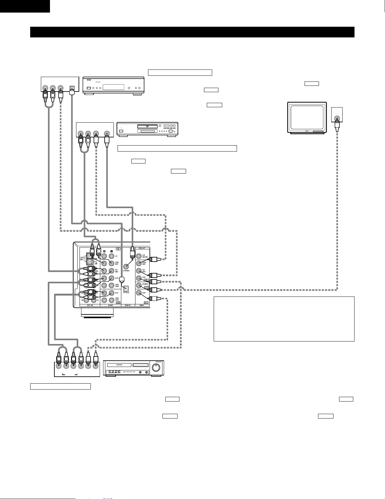
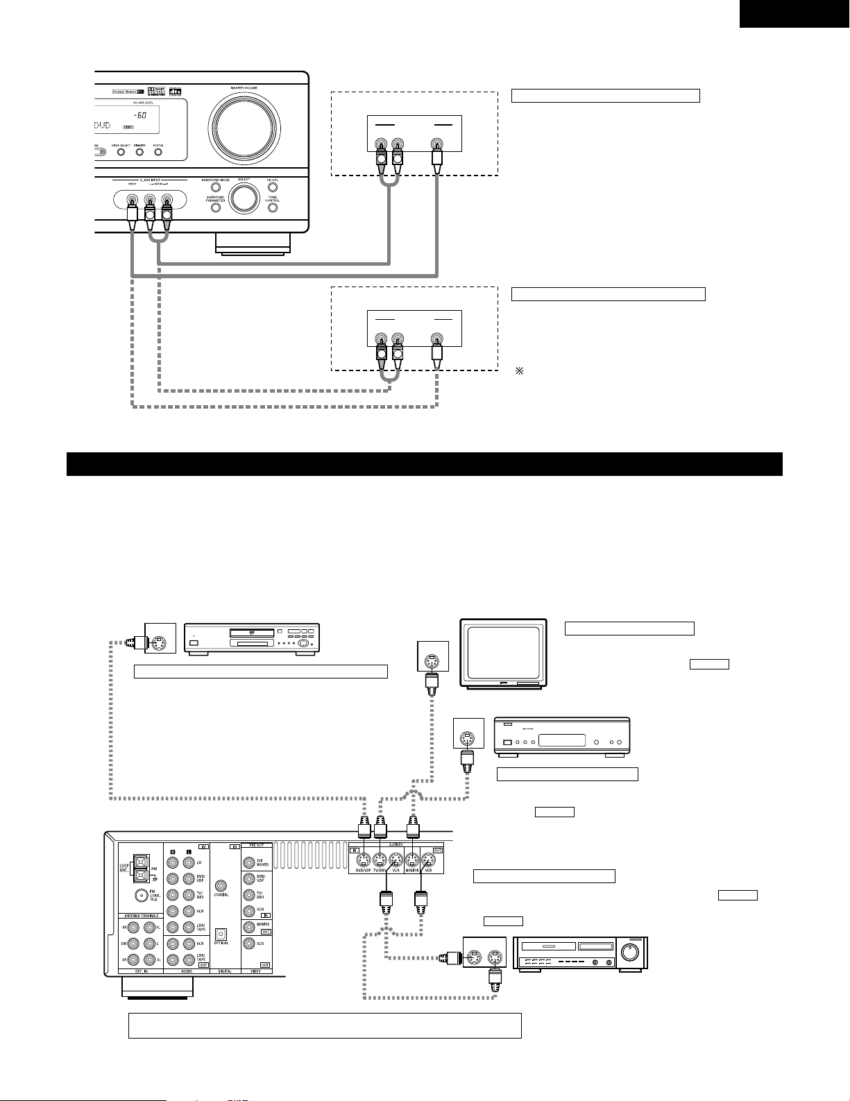
Connecting the video equipments
To connect the video signal, connect using a 75 Ω/ohms video signal cable cord. Using an improper cable can result in a drop in sound quality.
IN
VIDEO
R
L
R
L
R
L
L
R
R OUT IN
AUDIO
VIDEO
OUT IN
LRL
R
L
R
L
R OUT
VIDEO
OUT
L
AUDIO
OUT
COAXIAL
DIGITAL
L
R
R OUT
VIDEO
OPTICAL
OUT
L
AUDIO
OUT
DIGITAL
L
R
B
B
TV or DBS tuner
DVD player or VDP
Monitor TV
Connecting a TV/DBS tuner
TV/DBS
• Connect the TV’s or DBS tuner’s video output jack
(VIDEO OUTPUT) to the (yellow) TV/DBS IN
jack using a 75 Ω/ohms video coaxial pin plug cord.
• Connect the TV’s or DBS tuner’s audio output jacks
(AUDIO OUTPUT) to the TV/DBS IN jacks
using pin plug cords.
AUDIO
VIDEO
Connecting a DVD player or a video disc player (VDP)
• Connect the DVD player’s (video disc player’s) video output jack (VIDEO OUTPUT) to
the (yellow) DVD/VDP IN jack using a 75 Ω/ohms video coaxial pin plug cord.
• Connect the DVD player’s (video disc player’s) analog audio output jacks (ANALOG
AUDIO OUTPUT) to the DVD/VDP IN jacks using pin plug cords.
• For better sound quality, we recommend using the DVD player with digital rather than
analog connections.
DVD and VDP players can also be connected to the VCR terminals.
AUDIO
VIDEO
MONITOR OUT
• Connect the TV’s video input jack (VIDEO
INPUT) to the MONITOR OUT
jack using a 75 Ω/ohms video coaxial pin
plug cord.
VIDEO
NOTE:
Connection of the video disc Player Equipped with Dolby Digital RF
Output Jack.
• Please use a commercially available adaptor when connecting the
Dolby Digital RF output jack of the video disc player to the digital
input jack.
Please refer to the instruction manual of the adapter when making
connections.
Video deck
Video input/output connections:
• Connect the video deck’s video output jack (VIDEO OUT) to the (yellow) VCR IN jack, and the video deck’s video input jack (VIDEO IN) to the
(yellow) VCR OUT jack using 75 Ω/ohms video coaxial pin plug cords.
Connecting the audio output jacks:
• Connect the video deck’s audio output jacks (AUDIO OUT) to the VCR IN jacks, and the video deck’s audio input jacks (AUDIO IN) to the VCR OUT
jacks using pin plug cords.
AUDIOAUDIO
VIDEOVIDEO
Connecting a video decks
VIDEO OUT
VIDEO IN
VIDEO IN
AUDIO OUT
VIDEO OUT
VIDEO OUT
AUDIO OUT
AUDIO OUT
AUDIO IN
11
ENGLISH
Connecting a video component equipped with S-video jacks
• When marking connections, also refer to the operating instructions of the other components.
• A note on the S input jacks
The input selectors for the S inputs and pin jack inputs work in conjunction with each other.
• Precaution when using S-jacks
This unit’s S-jacks (input and output) and video pin jacks (input and output) have independent circuit structures, so that video signals input from
the S-jacks are only output from the S-jack outputs and video signals input from the pin jacks are only output from the pin jack outputs.
When connecting this unit with equipment that is equipped with S-jacks, keep the above point in mind and make connections according to the
equipment’s instruction manuals.
IN
S-VIDEO
OUT
S-VIDEO
OUT
S-VIDEO
OUT IN
S-VIDEO
VIDEO IN
VIDEO OUT
VIDEO IN
VIDEO OUT
VIDEO OUT
B
B
DVD player, VDP, etc.
Connecting a DVD player or video disc player (VDP)
DVD/VDP
• Connect the DVD player’s or video disc player’s S-
Video output jack to the S-VIDEO DVD/VDP IN jack
using an S-Video connection cord.
Connecting a monitor TV
MONITOR OUT
• Connect the TV’s or DBS tuner’s S video input
(S-VIDEO INPUT) to the MONITOR
OUT jack using a S jack connection cord.
S-VIDEO
Monitor TV
Connecting a TV/DBS tuner
• Connect the TV’s or DBS tuner’s S
video output jack (S-VIDEO OUTPUT)
to the TV/DBS IN jack using
an S jack connection cord.
S-VIDEO
TV or satellite broadcast tuner
Video deck
Connecting the video decks
• Connect the video deck’s S output jack (S-OUT) to the
VCR IN jack and the video deck’s S input jack (S-IN) to the
VCR OUT jack using S jack connection cords.
S-VIDEO
S-VIDEO
Connect the components’ audio inputs and outputs as described on page 10.
R VIDEO OUTL
OUTPUT
LINE OUT
VIDEO OUT
VIDEO OUT
LINE OUT
R VIDEO OUTL
OUTPUT
L
R
L
R
L
R
Connecting a Video game equipment
• Connect the Video game equipment’s output jacks to this
unit’s V. AUX INPUT jacks.
Video game
Video camera
Connecting a Video Camera equipment
• Connect the Video Camera equipment’s output jacks to this
unit’s V. AUX INPUT jacks.
The V. AUX terminal is covered with a cap. Remove this
cap in order to use the terminal. (See page 4 for
instructions on removing the cap.)
12
ENGLISH
1
4
2
3
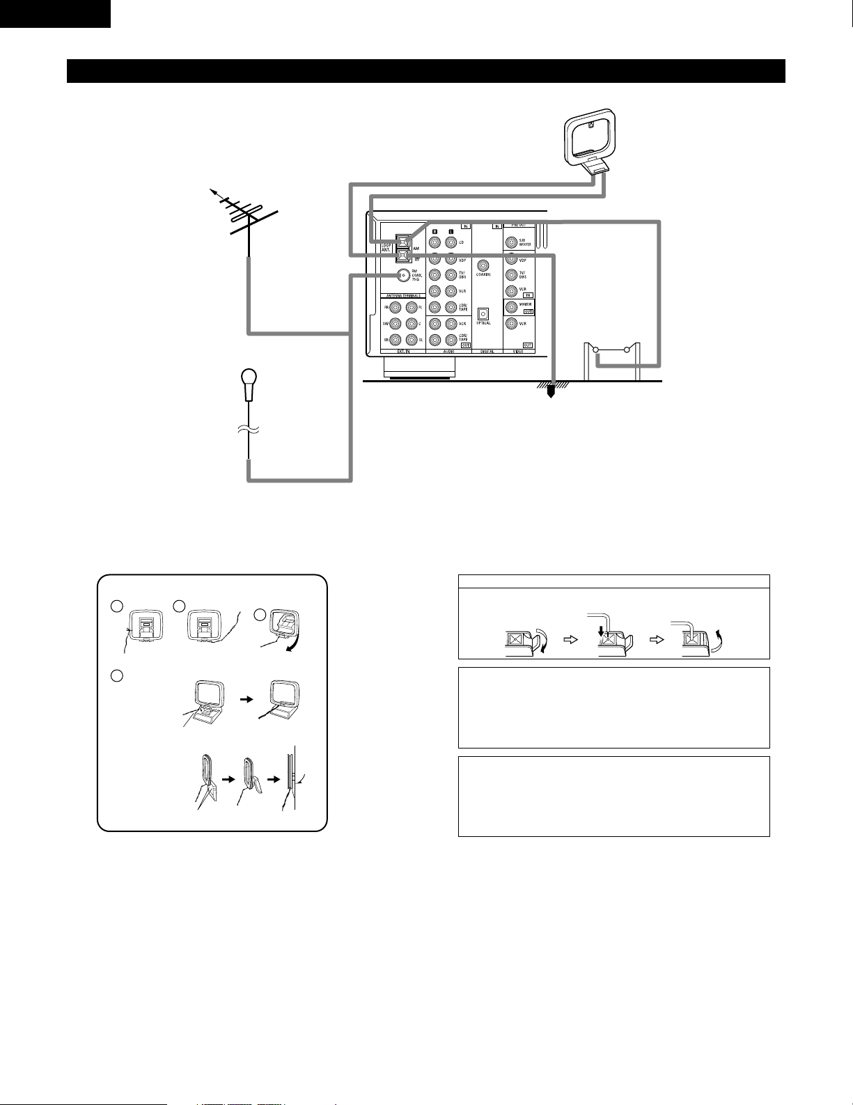
Connecting the antenna terminals
DIRECTION OF
BROADCASTING
STATION
AM LOOP
ANTENNA
(An Accessory)
FM ANTENNA
GROUND
AM OUTDOOR
ANTENNA
FM INDOOR
ANTENNA
(An Accessory)
75 Ω/ohms
COAXIAL
CABLE
AM loop antenna assembly
Connect to the AM
antenna terminals.
Bend in the reverse
direction.
Remove the vinyl tie
and take out the
connection line.
a. With the antenna
on top any stable
surface.
b. With the antenna
attached to a
wall.
Mount
Installation hole
Mount on wall, etc.
Connection of AM antennas
1. Push the lever. 2. Insert the
conductor.
3. Return the lever.
Note to CATV system installer:
This reminder is provided to call the CATV system installer’s
attention to Article 820-40 of the NEC which provides guidelines
for proper grounding and, in particular, specifies that the cable
ground shall be connected to the grounding system of the building,
as close to the point of cable entry as practical.
Notes:
• Do not connect two FM antennas simultaneously.
• Even if an external AM antenna is used, do not disconnect the AM
loop antenna.
• Make sure AM loop antenna lead terminals do not touch metal
parts of the panel.
13
ENGLISH
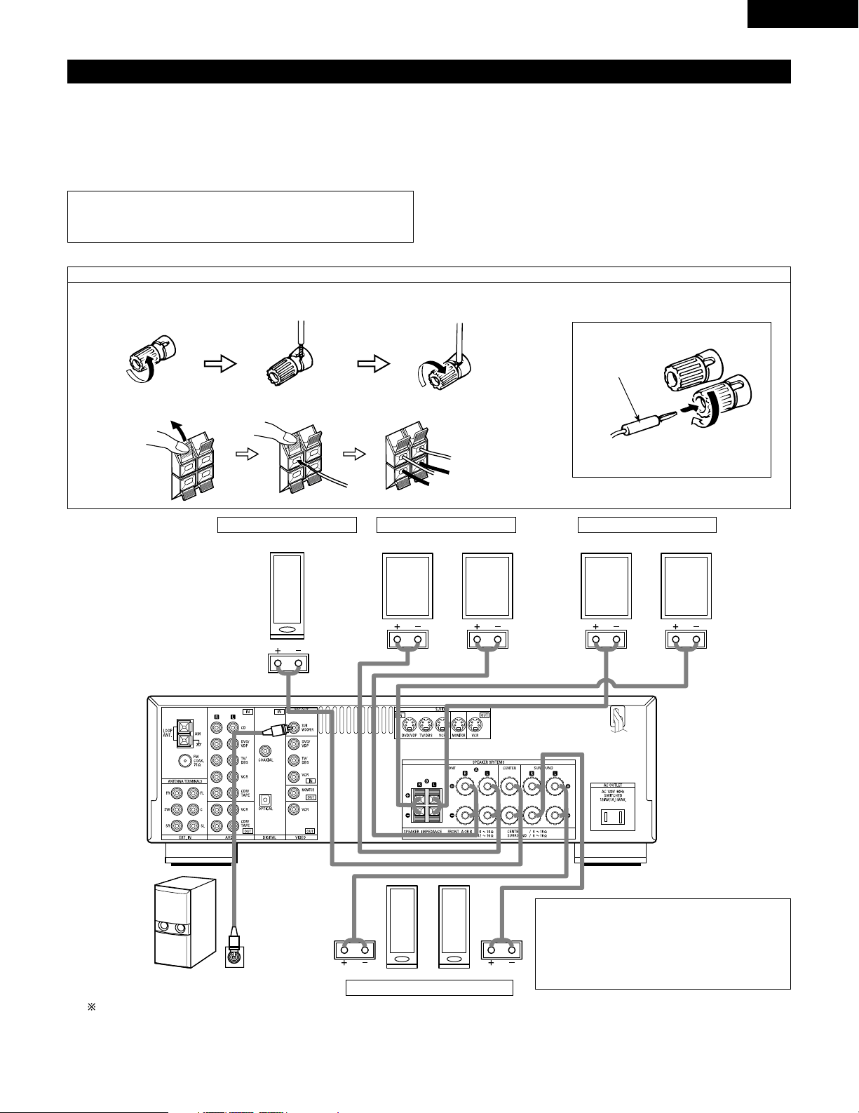
Speaker system connections
• Connect the speaker terminals with the speakers making sure that like
polarities are matched (< with <, > with >). Mismatching of polarities will
result in weak central sound, unclear orientation of the various instruments,
and the sense of direction of the stereo being impaired.
• When making connections, take care that none of the individual conductors
of the speaker cord come in contact with adjacent terminals, with other
speaker cord conductors, or with the rear panel.
Speaker Impedance
• When speaker systems A and B are use separately, speakers with an
impedance of 6 to 16 Ω/ohms can be connected for use as front speakers.
• Be careful when using two pairs of front speakers (A + B) at the same time,
since use of speakers with an impedance of 12 to 16 Ω/ohms.
• Speakers with an impedance of 6 to 16 Ω/ohms can be connected for use
as center and surround speakers.
• The protector circuit may be activated if the set is played for long periods of
time at high volumes when speakers with an impedance lower than the
specified impedance are connected.
NOTE:
• NEVER touch the speaker terminals when the power is on. Doing so
could result in electric shocks.
Connecting the speaker cords
1. Loosen by turning
counterclockwise.
2. Insert the cord. 3. Tighten by turning
clockwise.
Connecting banana plugs
Turn clockwise to tighten, then insert the
banana plug.
(
L
)(
R
)
(
L
) (
R
)(
L
) (
R
)
Connection jack for subwoofer with built-in
amplifier (super woofer), etc.
To achieve Dolby Digital playback effect,
use a unit that can sufficiently reproduce
frequencies of under 80 Hz.
SURROUND SPEAKER SYSTEMS
CENTER SPEAKER SYSTEM
FRONT SPEAKER SYSTEMS
• Precautions when connecting speakers
If a speaker is placed near a TV or video monitor, the
colors on the screen may be disturbed by the
speaker’s magnetism. If this should happen, move
the speaker away to a position where it does not
have this effect.
banana plug
1. Push the lever. 2. Insert the cord. 3. Return the lever.
System B
FRONT SPEAKER SYSTEMS
System A
14
ENGLISH
Protector circuit
• This unit is equipped with a high-speed protection circuit. The purpose of this circuit is to protect the speakers under
circumstances such as when the output of the power amplifier is inadvertently short-circuited and a large current flows,
when the temperature surrounding the unit becomes unusually high, or when the unit is used at high output over a long
period which results in an extreme temperature rise.
When the protection circuit is activated, the speaker output is cut off and the power supply indicator LED flashes. Should
this occur, please follow these steps: be sure to switch off the power of this unit, check whether there are any faults with
the wiring of the speaker cables or input cables, and wait for the unit to cool down if it is very hot. Improve the ventilation
condition around the unit and switch the power back on.
If the protection circuit is activated again even though there are no problems with the wiring or the ventilation around the
unit, switch off the power and contact a DENON service center.
Note on speaker impedance
• The protector circuit may be activated if the set is played for long periods of time at high volumes when speakers with
an impedance lower than the specified impedance (for example speakers with an impedance of lower than 4 Ω/ohms)
are connected. If the protector circuit is activated, the speaker output is cut off. Turn off the set’s power, wait for the set
to cool down, improve the ventilation around the set, then turn the power back on.
15
ENGLISH
9
USING THE REMOTE CONTROL UNIT
Following the procedure outlined below, insert the batteries before using the remote control unit.
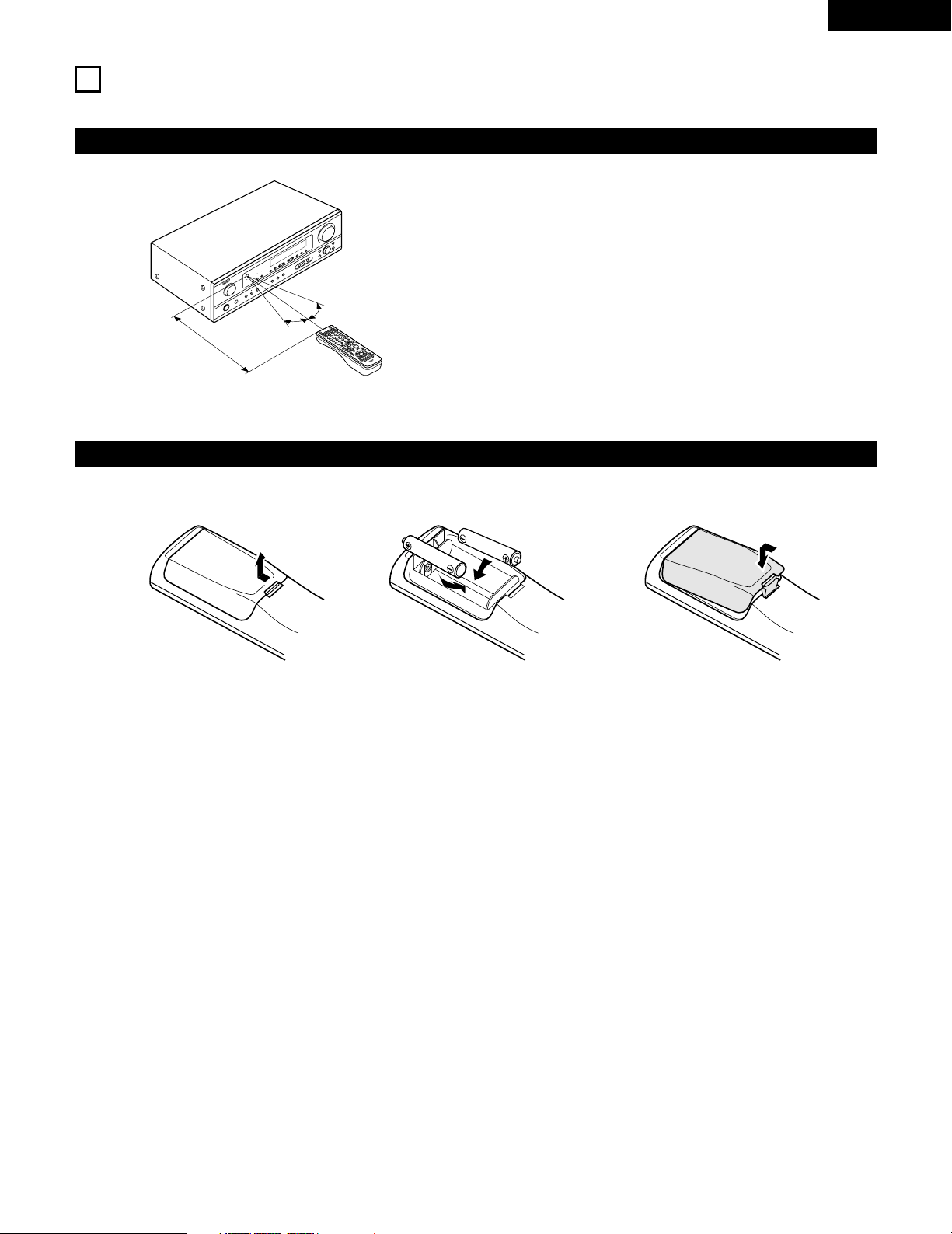
Range of operation of the remote control unit
Inserting the batteries
Point the remote control unit at the remote control sensor as shown
on the diagram at the left.
NOTES:
• The remote control unit can be used from a straight distance of
approximately 23 feet / 7 meters, but this distance will shorten or
operation will become difficult if there are obstacles between the
remote control unit and the remote control sensor, if the remote
control sensor is exposed to direct sunlight or other strong light, or
if operated from an angle.
• Neon signs or other devices emitting pulse-type noise nearby may
result in malfunction, so keep the set as far away from such
devices as possible.
Approx. 23 feet / 7 m
30°
30°
w Insert the R6P/AA batteries properly, as
shown on the diagram.
q Press as shown by the arrow and slide
off.
e Close the lid.
NOTES:
• Use only R6P/AA batteries for replacement.
• Be sure the polarities are correct. (See the illustration inside the battery compartment.)
• Remove the batteries if the remote control transmitter will not be used for an extended period of time.
• If batteries leak, dispose of them immediately. Avoid touching the leaked material or letting it come in contact with clothing, etc. Clean the
battery compartment thoroughly before installing new batteries.
• Have replacement batteries on hand so that the old batteries can be replaced as quickly as possible when the time comes.
• Even if less than a year has passed, replace the batteries with new ones if the set does not operate even when the remote control unit is
operated nearby the set. (The included battery is only for verifying operation. Replace it with a new battery as soon as possible.)
16
ENGLISH
10
SETTING UP THE SYSTEM
• Once all connections with other AV components have been completed as described in “CONNECTIONS” (see pages 9 to 14), make the
various settings described below on the display.
These settings are required to set up the listening room’s AV system centered around the this unit.
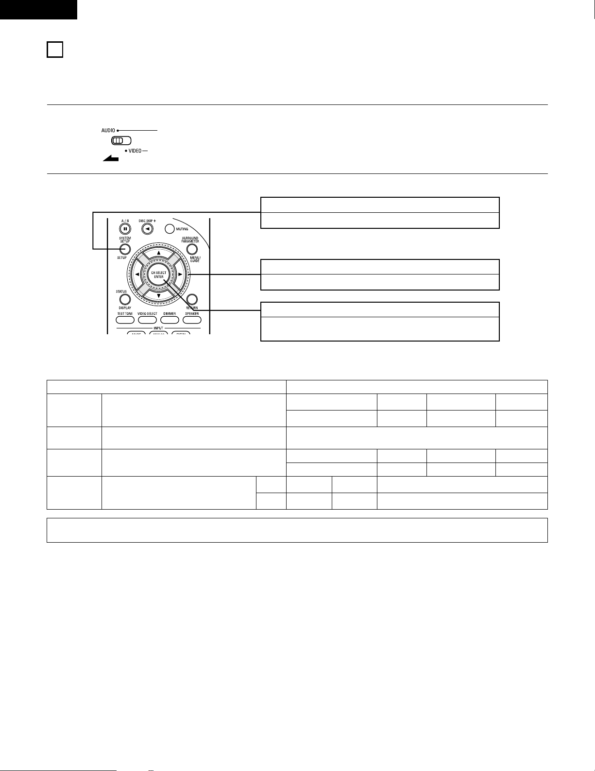
SYSTEM SETUP button
Press this to display the system setup on the display.
CURSOR buttons (•, ª, 0, 1)
Press this change what appears on the display.
ENTER button
Press this to switch the display.
Also use this button to complete the setting.
• System setup items and default values (set upon shipment from the factory)
System setup Default settings
Speaker
Configuration
Subwoofer Mode
Digital In
Assignment
Input the combination of speakers in your system and their
corresponding sizes (SMALL for regular speakers, LARGE for full-size,
full-range) to automatically set the composition of the signals output
from the speakers and the frequency response.
This assigns the digital input jacks for the different input
sources.
Input
source
Digital
Inputs
Front Sp.
Large
Center Sp. Surround Sp. Sub Woofer
Small Small Yes
Front & Subwoofer Center Surround L & R —
12 ft (3.6 m) 12 ft (3.6 m) 10 ft (3.0 m) —
DVD/VDP TV/DBS
COAXIAL OPTICAL
Delay Time
This parameter is for optimizing the timing with which the audio
signals are produced from the speakers and subwoofer according to
the listening position.
1
Set the slide switch to “AUDIO”.
2
Use the following buttons to set up the system:
This selects the subwoofer speaker for playing deep bass
signals.
Subwoofer mode = Normal
NOTE:
• The system setup is not displayed when “HEADPHONE ONLY” is selected.
17
ENGLISH
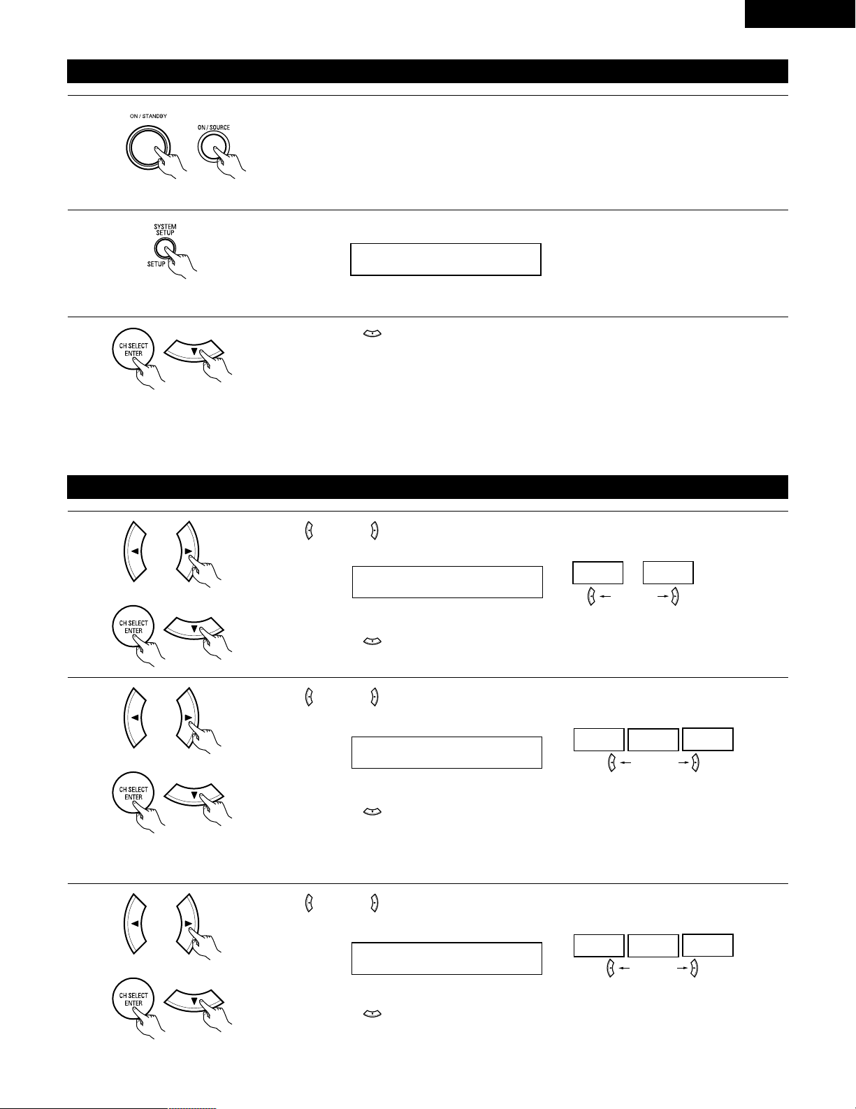
Before setting up the system
1
2
Press the SYSTEM SETUP button to enter the setting.
Check that all the components are correct, then press the POWER operation switch on the main unit or
the POWER button on the remote control unit to turn on the power.
3
Press the ENTER or (down) button to switch to the speaker configuration set up.
*SYSTEM SET UP
NOTE:
Press the SYSTEM SETUP button again to finish system set up. System set up can be finished at any time. The changes to the settings
made up to that point are entered.
NOTE: Please make sure the “AUDIO” position of the slide switch on the remote control unit.
(Main unit) (Remote control unit)
Setting the speaker configuration
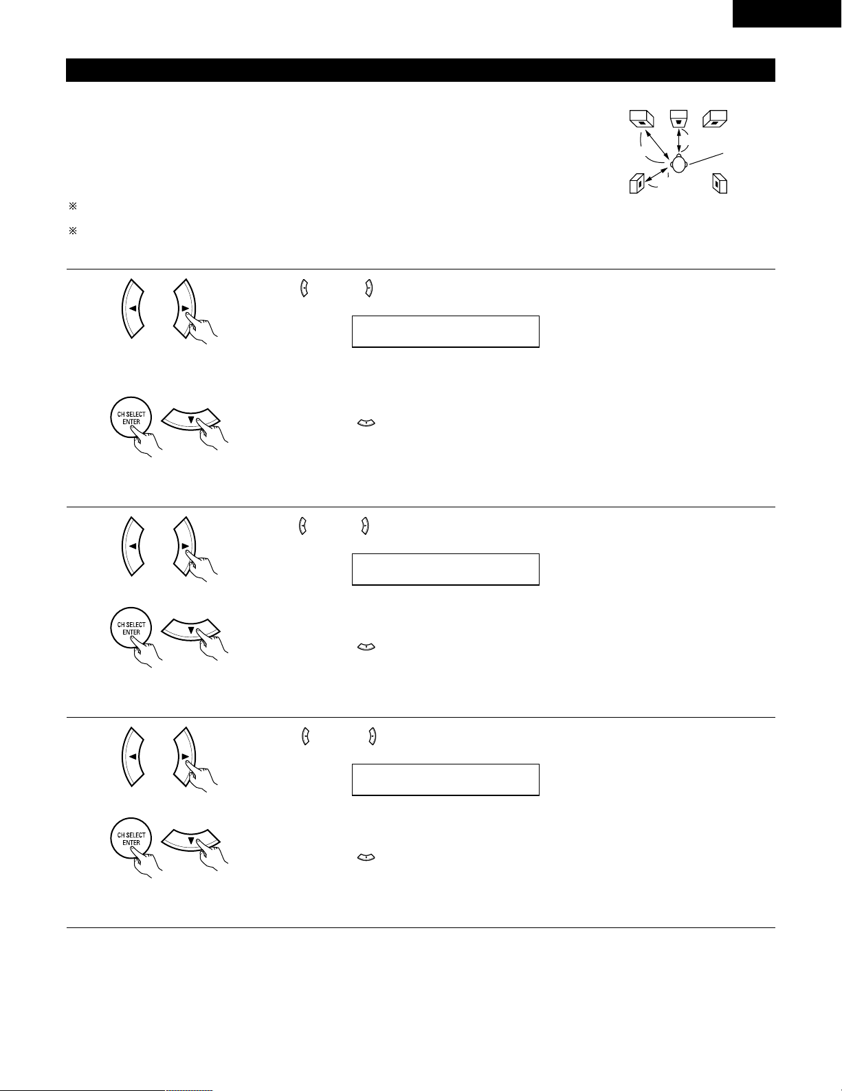
1
Use the (left) and (right) buttons to select your front speaker type.
1 FRONT LARGE
LARGE
SMALL
(left) button (right) button
Press the ENTER or (down) button to switch to the center speaker setting.
2
Use the (left) and (right) buttons to select your center speaker type.
2 CENTER SMALL
LARGE
SMALL
NONE
(left) button (right) button
Press the ENTER or (down) button to switch to the surround speaker setting.
3
Use the (left) and (right) buttons to select your surround speaker type.
3 SURR. SMALL
LARGE
SMALL
NONE
(left) button (right) button
Press the ENTER or (down) button to switch to the subwoofer setting.
NOTE:
• When “Small” has been selected for the front speakers, “Large” cannot be selected for the center speaker.
(Initial)
(Initial)
(Initial)
18
ENGLISH
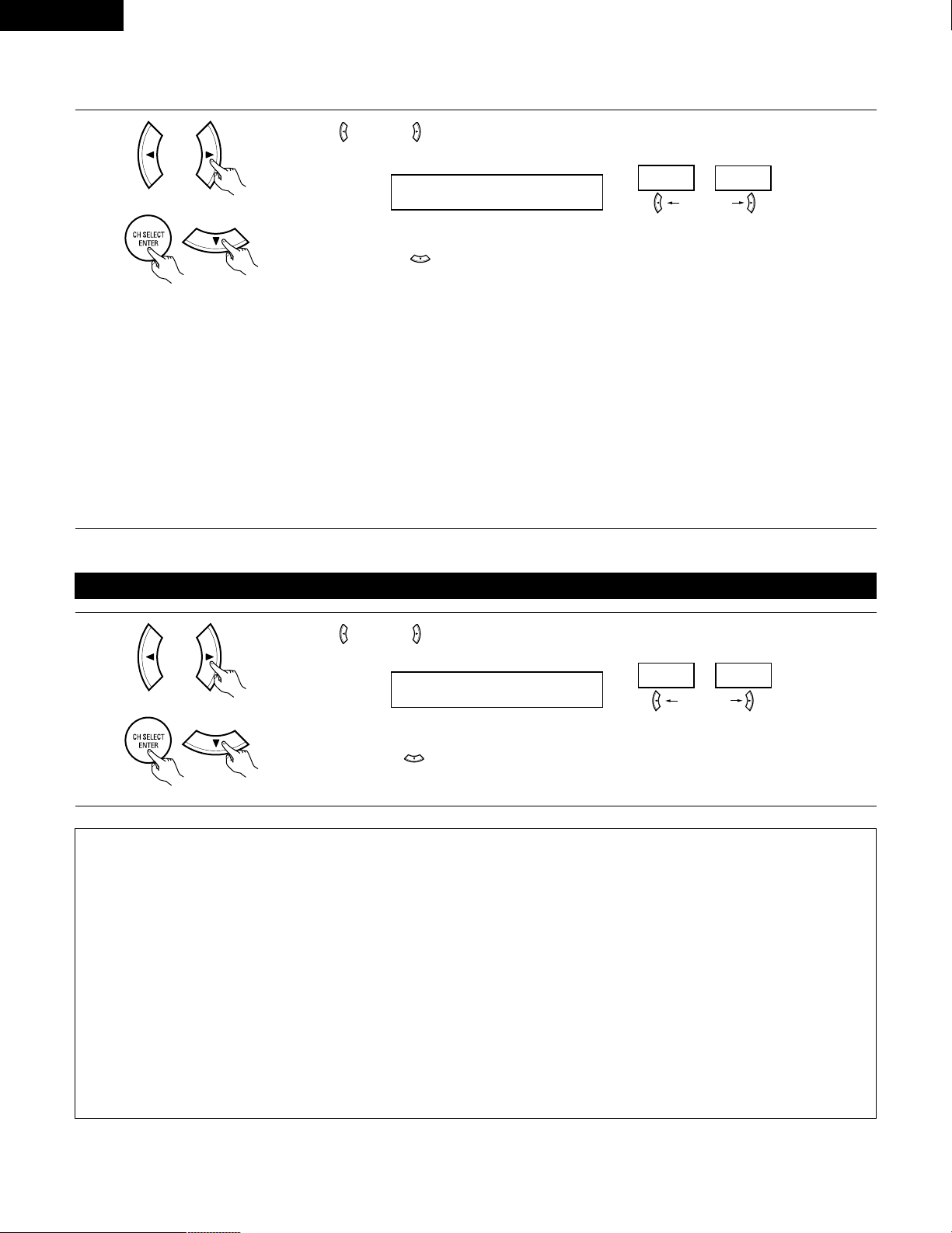
NOTE:
• When “Small” has been selected for the front speakers, “Large” cannot be selected for the surround speakers.
4
Use the (left) and (right) buttons to select your subwoofer setting.
4 S.WOOFER YES
YES
NO
(left) button (right) button
Press the ENTER or (down) button to enter the settings and switch to the SUBWOOFER MODE
setting.
• Parameters
Large…… Select this when using speakers that can fully reproduce low sounds of below 80 Hz.
Small…… Select this when using speakers that cannot reproduce low sounds of below 80 Hz with sufficient volume. When this setting is
selected, low frequencies of below 80 Hz are assigned to the subwoofer.
None…… Select this when no speakers are installed.
Yes/No…. Select “Yes” when a subwoofer is installed, “No” when it’s not installed.
NOTE:
Select “Large” or “Small” not according to the physical size of the speaker, but according to the bass reproduction capacity at 80 Hz. If you cannot
determine the best setting, try comparing the sound when set to “Small” and when set to “Large”, at a level that will not damage the speakers.
Caution:
In case the subwoofer is not used, be sure to set “Subwoofer = No”, or the bass sound of front channel is divided to subwoofer channel and
not reproduced in some mode.
Setting the Subwoofer mode
1
Use the (left) and (right) buttons to select the Subwoofer mode.
5 SW MODE NORM
NORM +MAIN
(left) button (right) button
Press the ENTER or (down) button to enter the setting and switch to the Speaker Distance setting.
(Initial)
(Initial)
NOTES:
— Assignment of low frequency signal range —
• The signals produced from the subwoofer channel are LFE signals (during playback of Dolby Digital or DTS signals) and the low frequency
signal range of channels set to “SMALL” in the setup. The low frequency signal range of channels set to “LARGE” are produced from those
channels.
— Subwoofer mode —
• The subwoofer mode setting is only valid when “LARGE” is set for the front speakers and “YES” is set for the subwoofer in the “Speaker
Configuration” settings (see pages 17, 18).
If “SMALL” is set for the front speakers or “NO” is set for the subwoofer, the subwoofer mode setting does not affect playback of low
frequency signal range.
• When the “+MAIN” playback mode is selected, the low frequency signal range of channels set to “LARGE” are produced simultaneously
from those channels and the subwoofer channel.
In this playback mode, the low frequency range expand more uniformly through the room, but depending on the size and shape of the room,
interference may result in a decrease of the actual volume of the low frequency range.
• When the “NORM” playback mode is selected, the low frequency signal range of channels set to “LARGE” are only produced from those
channels. In this playback mode there tends to be little interference of the low frequency range in the room.
• Try playing the music or movie source and select the playback mode providing the stronger low frequency range sound.
19
ENGLISH
Setting the speaker distance
Input the distances from the listening position to the speakers and set the surround delay time.
Preparations:
Measure the distances from the listening position to the speakers (L1 to L3 on the diagram at the right).
L1: Distance from center speaker to listening position
L2: Distance from front speakers to listening position
L
3: Distance from surround speakers to listening position
CAUTION:
Set the center speaker at the same distance from the front speakers (left and right) or the subwoofer,
or so that the difference in distance (L2 – L1) is 5 feet or less.
Set the surround speakers (left and right) at the same distance from the front speakers (left and right)
or the subwoofer, or so that the difference in distance (L2 – L3) is 15 feet or less.
L1
L2
L3
FL
Center FR
Listening
position
SL
SR
1
Use the (left) and (right) buttons to set the distance from the front speakers and subwoofer to the
listening position.
6 FRNT/SW 12ft
• The number changes in units of 1 foot each time one of the buttons is pressed. Select the value closest
to the measured distance.
(“/SW” appears only when subwoofer = yes.)
Press the ENTER or (down) button to switch to the center speaker setting.
NOTE:
• The speaker distance can be adjusted between 0 and 60 feet in steps of 1 foot.
2
Use the (left) and (right) buttons to set the distance from the center speaker to the listening position.
7 CENTER 12ft
• The number changes in units of 1 foot each time one of the buttons is pressed. Select the value closest
to the measured distance.
Press the ENTER or (down) button to switch to the surround speakers setting.
NOTE:
• No setting when “None” has been selected for the center speaker.
3
Use the (left) and (right) buttons to set the distance from the surround speakers to the listening
position.
8 SURR. 10ft
• The number changes in units of 1 foot each time one of the buttons is pressed. Select the value closest
to the measured distance.
Press the ENTER or (down) button to enter the setting and switch the DIGITAL input (COAX) setting.
NOTE:
• No setting when “None” has been selected for the surround speakers.
20
ENGLISH
Setting the Digital In assignment
Input the type of components connected to the digital input terminals.
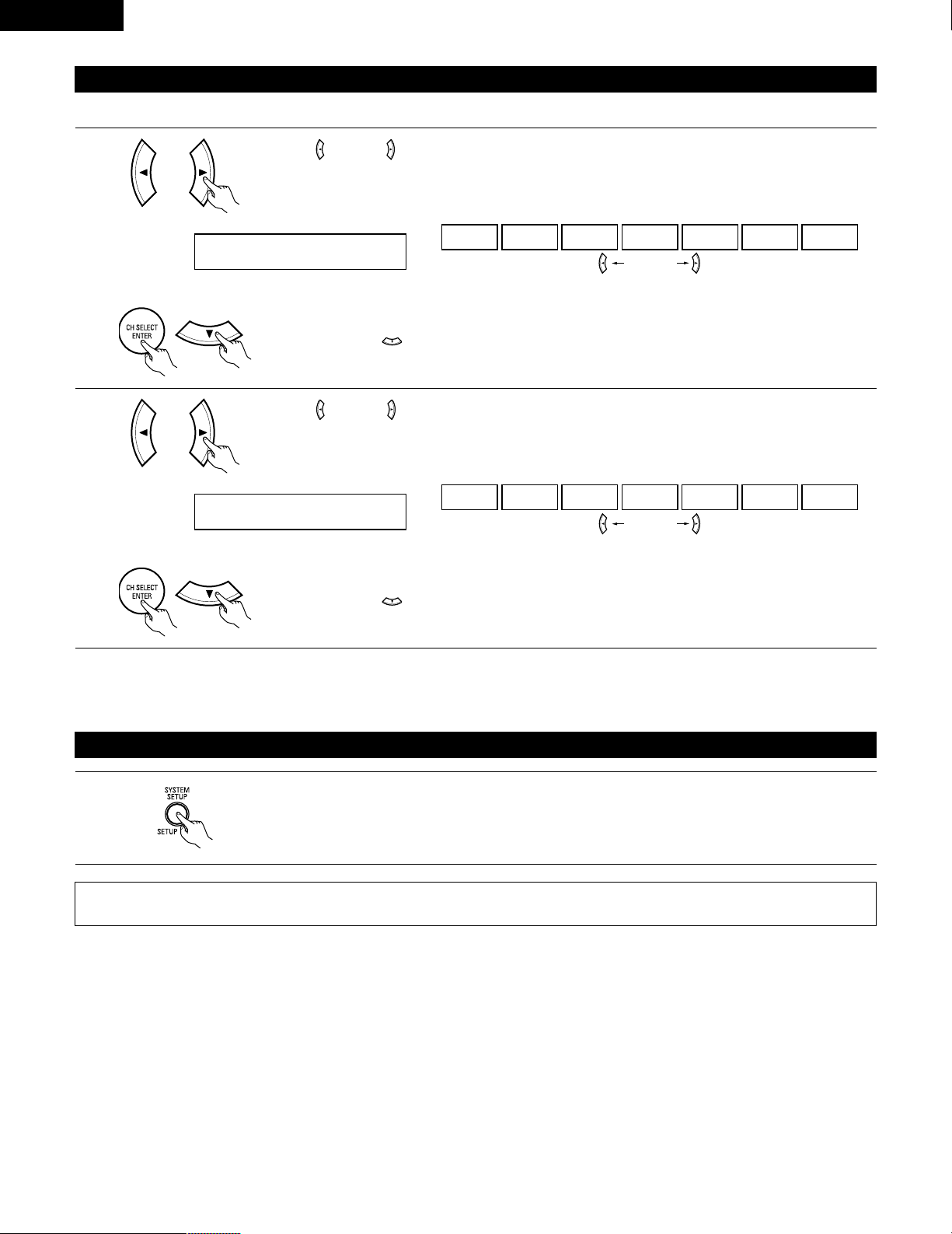
1
Use the (left) and (right) buttons to assign the input function connected to the COAXIAL input (COAXIAL)
terminal.
9 COAX DVD
CD DVD TV VCR V.AUX CDR OFF
• Select “OFF” if nothing is connected.
Press the ENTER or (down) button to switch the optical input (OPT) setting.
(left) button (right) button
2
Use the (left) and (right) buttons to assign the input function connected to the OPTICAL input (OPTICAL)
terminal.
10 OPT TV
CD DVD TV VCR V.AUX CDR OFF
• Select “OFF” if nothing is connected.
Press the ENTER or (down) button if you want to start the settings over from the beginning.
(left) button (right) button
(Initial)
(Initial)
NOTE:
• TUNER cannot be selected.
After setting up the system
1
Press the SYSTEM SETUP button to finish system set up.
This completes the system setup operations. Once the system is set up, there is no need to make the settings again unless other components
or speakers are connected to or the speaker layout is changed.
21
ENGLISH
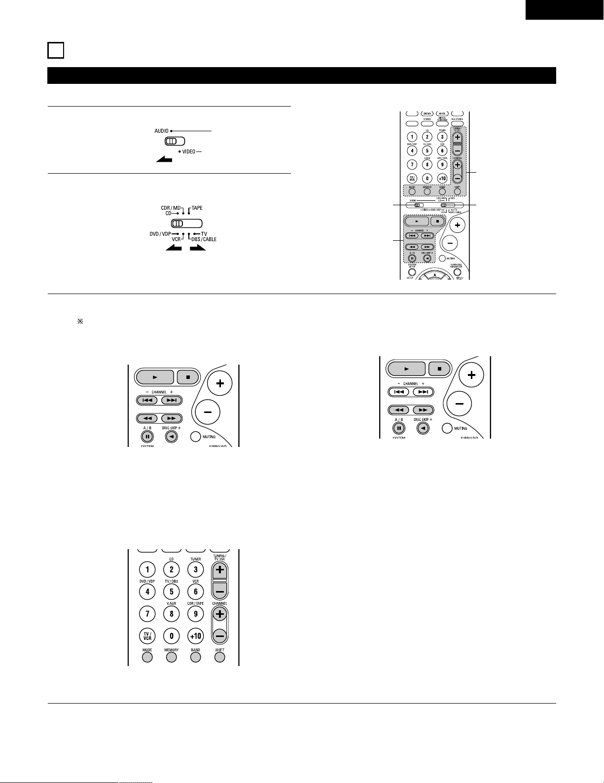
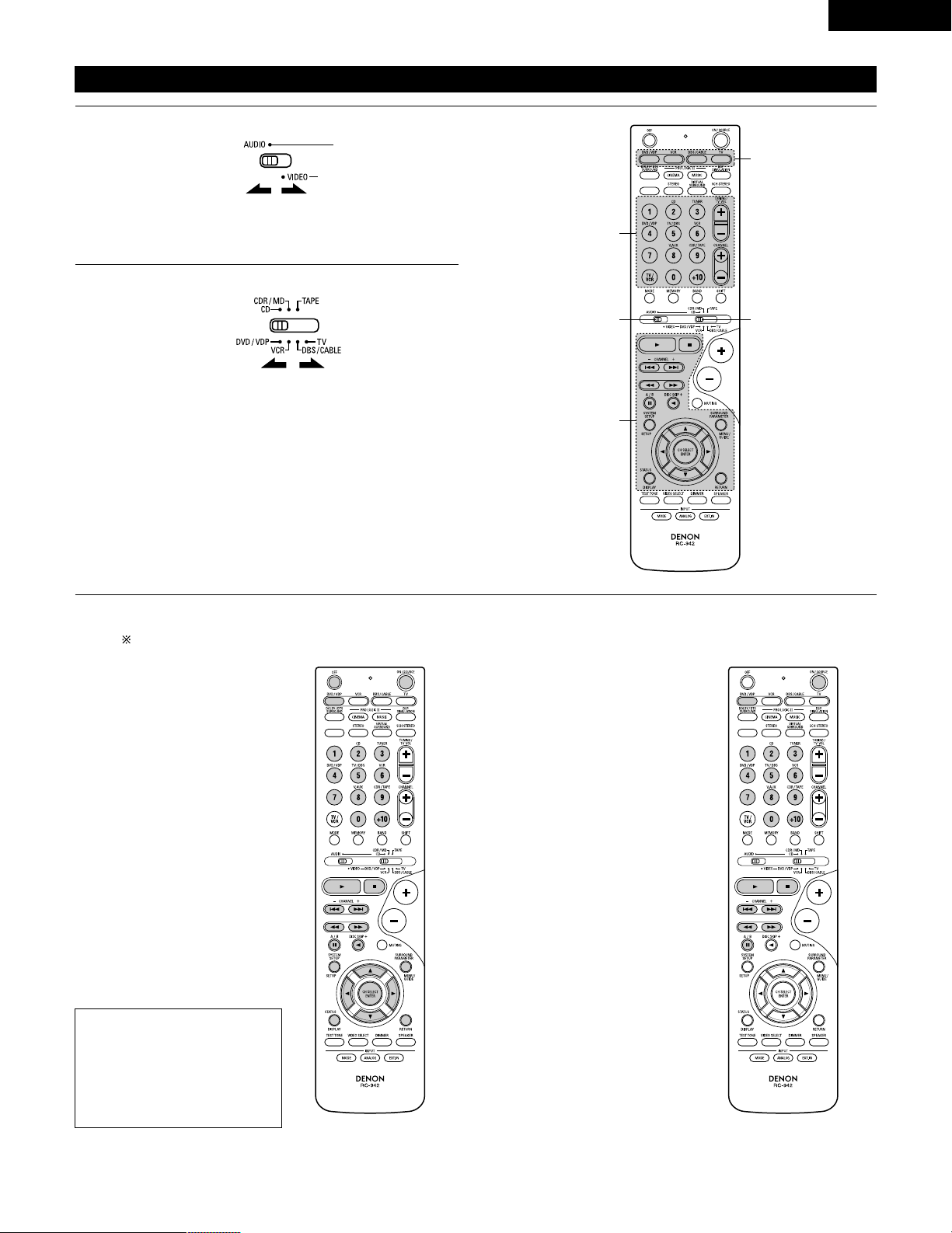
Operating DENON audio components
• Turn on the power of the different components before operating them.
1
2
3
Set mode switch 1 to “AUDIO”.
Set mode switch 2 to the position for the component to be
operated. (CD, CDR/MD or Tape deck)
Operate the audio component.
• For details, refer to the component’s operating instructions.
While this remote control is compatible with a wide range of infrared controlled components, some models of components may not
be operated with this remote control.
1. CD player (CD) and CD recorder and MD recorder
(CDR/MD) system buttons
3. Tuner system buttons
2. Tape deck (TAPE) system buttons
3
2
1
3
6, 7 : Manual search (forward and reverse)
2 : Stop
1 : Play
8, 9 : Auto search (cue)
3 : Pause
DISC : Switch discs
SKIP+ (for CD changers only)
SHIFT : Switch preset channel range
CHANNEL : Preset channel
+, – up/down
TUNING : Frequency
+, – up/down
BAND : Switch between the AM and FM bands
MODE : Switch between auto and mono
MEMORY : Preset memory
6 : Rewind
7 : Fast-forward
2 : Stop
1 : Forward play
0 : Reverse play
A/B : Switch between decks A and B
11
REMOTE CONTROL UNIT
NOTE:
• TUNER can be operated when the switch is at “AUDIO” position.
22
ENGLISH
Preset memory
DENON and other makes of components can be operated by setting the preset memory.
This remote control unit can be used to operate components of other manufacturers without using the learning function by registering the
manufacturer of the component as shown on the List of Preset Codes (pages 98~102).
Operation is not possible for some models.
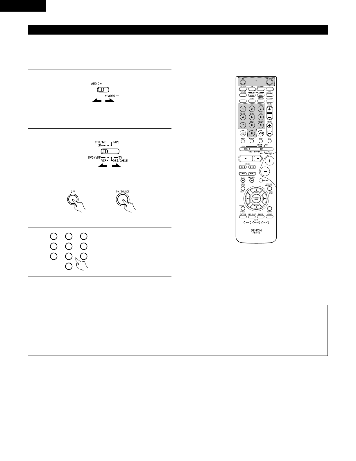
1
2
Set mode switch 1 to “AUDIO” or “VIDEO”.
Set mode switch 2 to the component to be registered.
3
2
1
4
Set the AUDIO side for the CD, Tape deck or CDR/MD
position, to the VIDEO side for the DVD/VDP, DBS/CABLE,
VCR or TV position.
3
Press the ON/SOURCE button and the OFF button at the
same time.
• Indicator flash.
4
5
Referring to the included List of
Preset Codes, use the number
buttons to input the preset code (a
3-digit number) for the
manufacturer of the component
whose signals you want to store in
the memory.
To store the codes of another component in the memory,
repeat steps 1 to 4.
The preset codes are as follows upon shipment from the factory and after resetting:
TV, VCR.....................................................HITACHI
CD, TAPE ..................................................DENON
CDR/MD ...................................................DENON (CDR)
DVD/VDP ..................................................DENON (DVD)
DBS/CABLE ..............................................ABC (CABLE)
NOTES:
• The signals for the pressed buttons are emitted while setting the preset memory. To avoid accidental operation, cover the remote control
unit’s transmitting window while setting the preset memory.
• Depending on the model and year of manufacture, this function cannot be used for some models, even if they are of makes listed on the
included list of preset codes.
• Some manufacturers use more than one type of remote control code. Refer to the included list of preset codes to change the number and
check.
• The preset memory can be set for one component only among the following: CDR/MD, DVD/VDP and DBS/CABLE.
1
2
3
456
789
0
23
ENGLISH
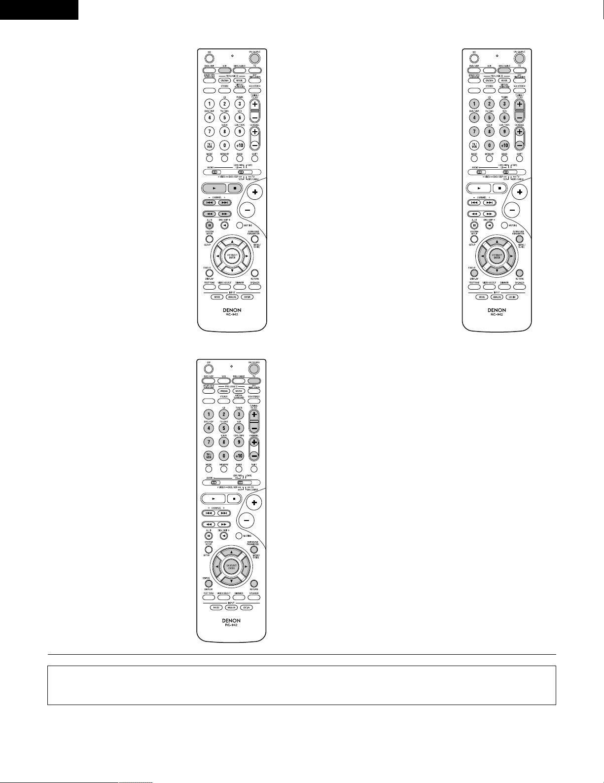
Operating component stored in the preset memory
1
2
Set mode switch 1 to “AUDIO” or “VIDEO”.
Set mode switch 2 to the component you want to operate.
3
2
1
3
3
Set the AUDIO side for the CD, tape deck or CDR/MD
position, to the VIDEO side for the DVD/VDP, DBS/CABLE,
VCR or TV position.
1. Digital video disc player (DVD,
DVD SETUP) system buttons
POWER : Power (on/standby)
(ON/SOURCE)
OFF : DENEN DVD power off
6,7 : Manual search
(forward and reverse)
2 : Stop
1 :Play
8,9 : Auto search
(to beginning of track)
3 : Pause
0 ~ 9, +10 : 10 key
skip + : Disc skip
(for DVD changer only)
DISPLAY : Switch display
MENU : Menu
RETURN : Return
SETUP : Setup
•, ª,
0
,
1
: Cursor up, down, left
and right
ENTER : Enter setting
2. Video disc player (VDP)
system buttons
POWER : Power on/standby
(ON/SOURCE)
6,7 : Manual search
(forward and reverse)
2 : Stop
1 :Play
8,9 : Auto search (cue)
3 : Pause
0~9, +10 : 10 key
3
Operate the component.
• For details, refer to the component’s operating instructions.
Some models cannot be operated with this remote control unit.
NOTE:
• Some manufacturers use
different names for the DVD
remote control buttons, so also
refer to the instructions on
remote control for that
component.
24
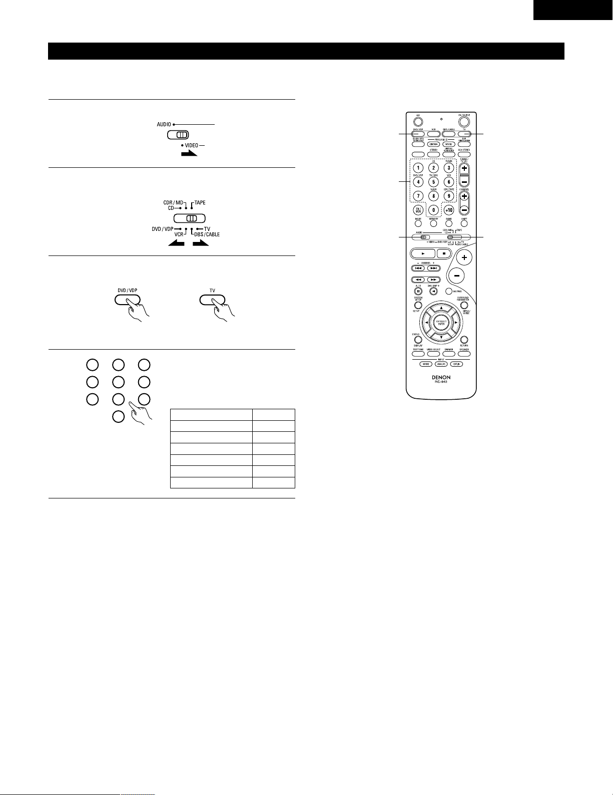
ENGLISH
3. Video deck (VCR) system
buttons
4. Digital broadcast satellite
(DBS) tuner and cable
(CABLE) system buttons
POWER : Power on/standby
(ON/SOURCE)
6,7 : Manual search
(forward and reverse)
2 : Stop
1 :Play
3 : Pause
Channel +, – : Channels
POWER : Power on/standby
(ON/SOURCE)
MENU : Menu
RETURN : Return
•, ª,
0
,
1
: Cursor up, down, left
and right
ENTER : Enter
CHANNEL : Switch channels
+, –
0~9, +10 : Channels
DISPLAY : Switch display
VOL +, – : Volume up/down
5. Monitor TV (TV) system
buttons
POWER : Power on/standby
(ON/SOURCE)
MENU : Menu
RETURN : Return
•, ª,
0
,
1
: Cursor up, down, left
and right
ENTER : Enter
CHANNEL : Switch channels
+, –
0~9, +10 : Channels
DISPLAY : Switch display
TV/VCR : Switch between TV
and video player
TV VOL : Volume up/down
+, –
NOTES:
• For this CD, CDR, MD and TAPE components, buttons can be operated in the same way as for Denon audio components (page 21).
• The TV can be operated when the switch is at DVD/VDP, VCR, TV position.
25
ENGLISH
Punch Through
•“Punch Through” is a function allowing you to operate the PLAY, STOP, MANUAL SEARCH and AUTO SEARCH buttons on the CD, TAPE,
CDR/MD, DVD/VDP or VCR components when in the DBS/CABLE or TV mode. By default, nothing is set.
1
2
Set mode switch 1 to “VIDEO”.
Set mode switch 2 to the component to be registered
(DBS/CABLE or TV).
3
2
1
4
3
3
Press the DVD/VDP power button and the TV power button at
the same time.
• Indicator flash.
4
Input the number of the
component you want to set. (See
Table 1)
1
2
3
456
789
0
Table 1
CD
TAPE
CDR/MD
DVD/VDP
VCR
No setting
No.
1
2
3
4
5
0
26
ENGLISH
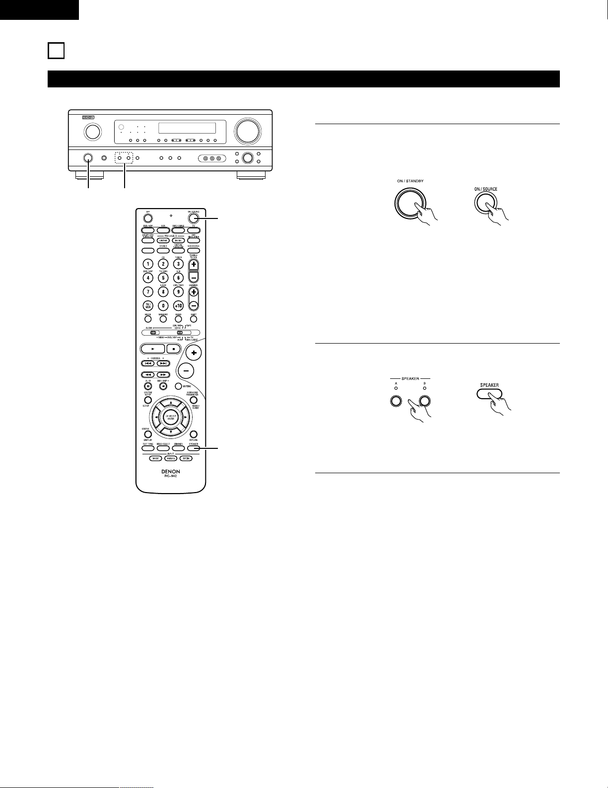
12
OPERATION
Before operating
Preparations:
Check that all connections are proper.
1
Turn on the power.
Press the ON/STANDBY button on the main unit or
ON/SOURCE button on the remote control unit to turn on the
power.
2
Select the front speakers.
Press the SPEAKER A or B button to turn the speaker on.
(Main unit) (Remote control unit)
1 2
1
2
• ON/STANDBY
When the button is pressed, the power turns on and the
display lights after approximately 1 second.
When pressed again, the power turns off, the standby
mode is set and the display turns off.
Several seconds are required from the time the power
operation switch is set to the “ON” position until sound is
output. This is due to the built-in muting circuit that
prevents noise when the power switch is turned on and off.
(Main unit) (Remote control unit)
• The front speaker A, B setting can be also be changed with
the SPEAKER button on the remote control unit.
27
ENGLISH
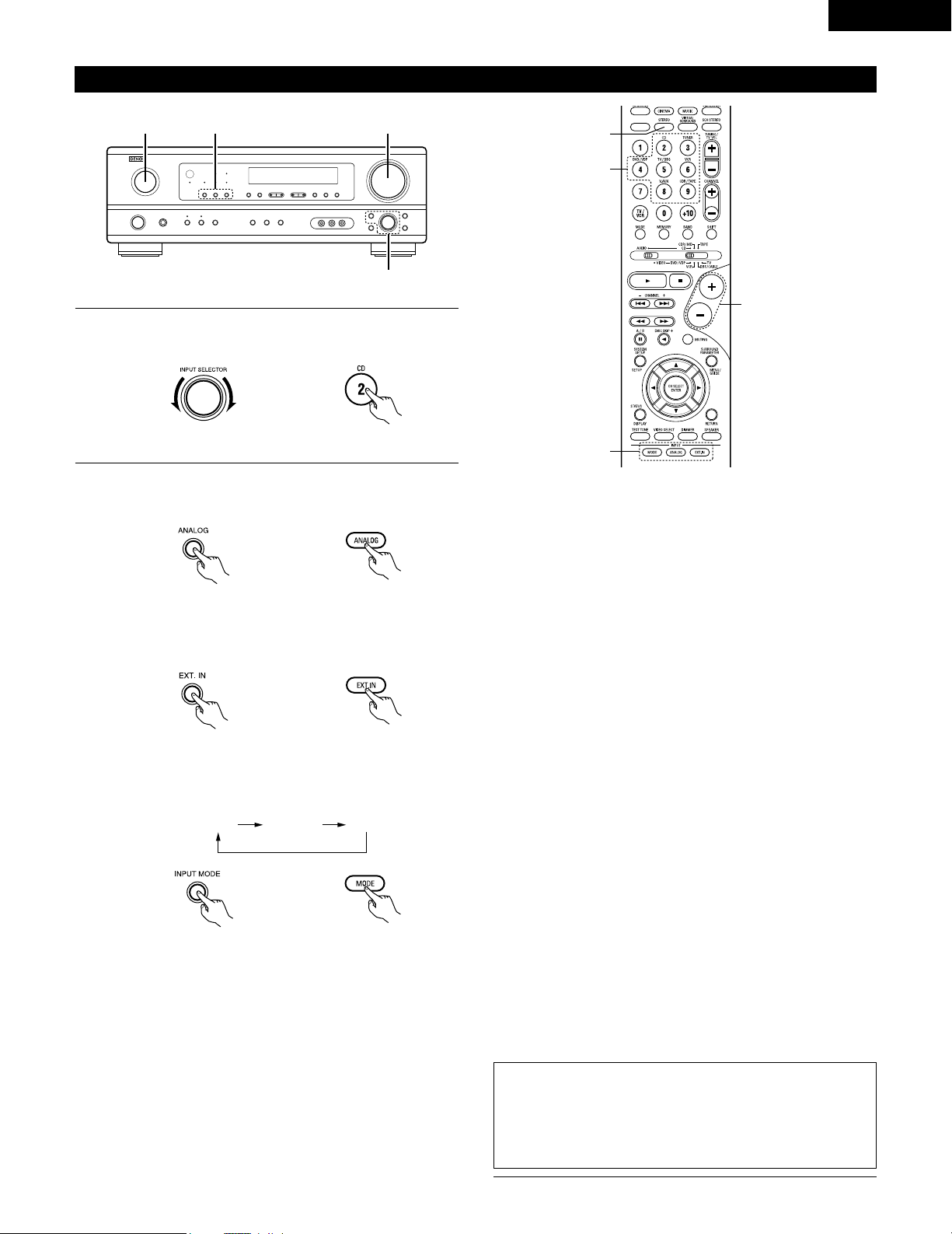
Playing the input source
3
1 2 5
Input mode selection function
Different input modes can be selected for the different input sources.
The selected input modes for the separate input sources are stored
in the memory.
q AUTO (All auto mode)
In this mode, the types of signals being input to the digital and
analog input jacks for the selected input source are detected and
the program in the this unit’s surround decoder is selected
automatically upon playback. This mode can be selected for all
input sources other than TUNER.
The presence or absence of digital signals is detected, the signals
input to the digital input jacks are identified and decoding and
playback are performed automatically in DTS, Dolby Digital or
PCM (2 channel stereo) format. If no digital signal is being input,
the analog input jacks are selected.
Use this mode to play Dolby Digital signals.
w PCM (exclusive PCM signal playback mode)
Decoding and playback are only performed when PCM signals are
being input.
Note that noise may be generated when using this mode to play
signals other than PCM signals.
e DTS (exclusive DTS signal playback mode)
Decoding and playback are only performed when DTS signals are
being input.
r ANALOG (exclusive analog audio signal playback mode)
The signals input to the analog input jacks are decoded and
played.
t EXT. IN (external decoder input jack selection mode)
The signals being input to the external decoder input jacks are
played without passing through the surround circuitry.
NOTE:
• Note that noise will be output when CDs or LDs recorded in DTS
format are played in the “PCM” (exclusive PCM signal playback) or
“ANALOG” (exclusive analog audio signal playback) mode. Select
the AUTO or DTS (exclusive DTS signal playback) mode when
playing signals recorded in DTS from a laser disc player.
Notes on playing a source encoded with DTS
• Noise may be generated at the beginning of playback and
while searching during DTS playback in the AUTO mode. If
so, play in the DTS mode.
•
In some rare cases the noise may be generated when you
preform the operation to stop playback of a DTS-CD or DTS-LD.
5
1
3
2
1
Select the input source to be played.
Example: CD
(Main unit) (Remote control unit)
2
Select the input mode.
• Selecting the analog mode
Press the ANALOG button to switch to the analog input.
(Remote control unit)
• Selecting the external input (EXT. IN) mode
Press the EXT. IN (or the EXT. IN button on the remote
control unit) to switch the external input.
(Main unit) (Remote control unit)
• Selecting the AUTO, PCM and DTS modes
The mode switches as shown below each time the INPUT
MODE button is pressed.
AUTO PCM DTS
(Main unit)
(Main unit) (Remote control unit)
28
ENGLISH
• To increase the bass or treble: Turn the control clockwise.
(The bass or treble sound can be increased to up to +10 dB
in steps of 2 dB.)
• To decrease the bass or treble: Turn the control
counterclockwise. (The bass or treble sound can be
decreased to up to –10 dB in steps of 2 dB.)
To select the surround mode while adjusting
the surround parameters, channel volume or
tone control, press the surround mode
button then operate the selector.
(See page 32.)
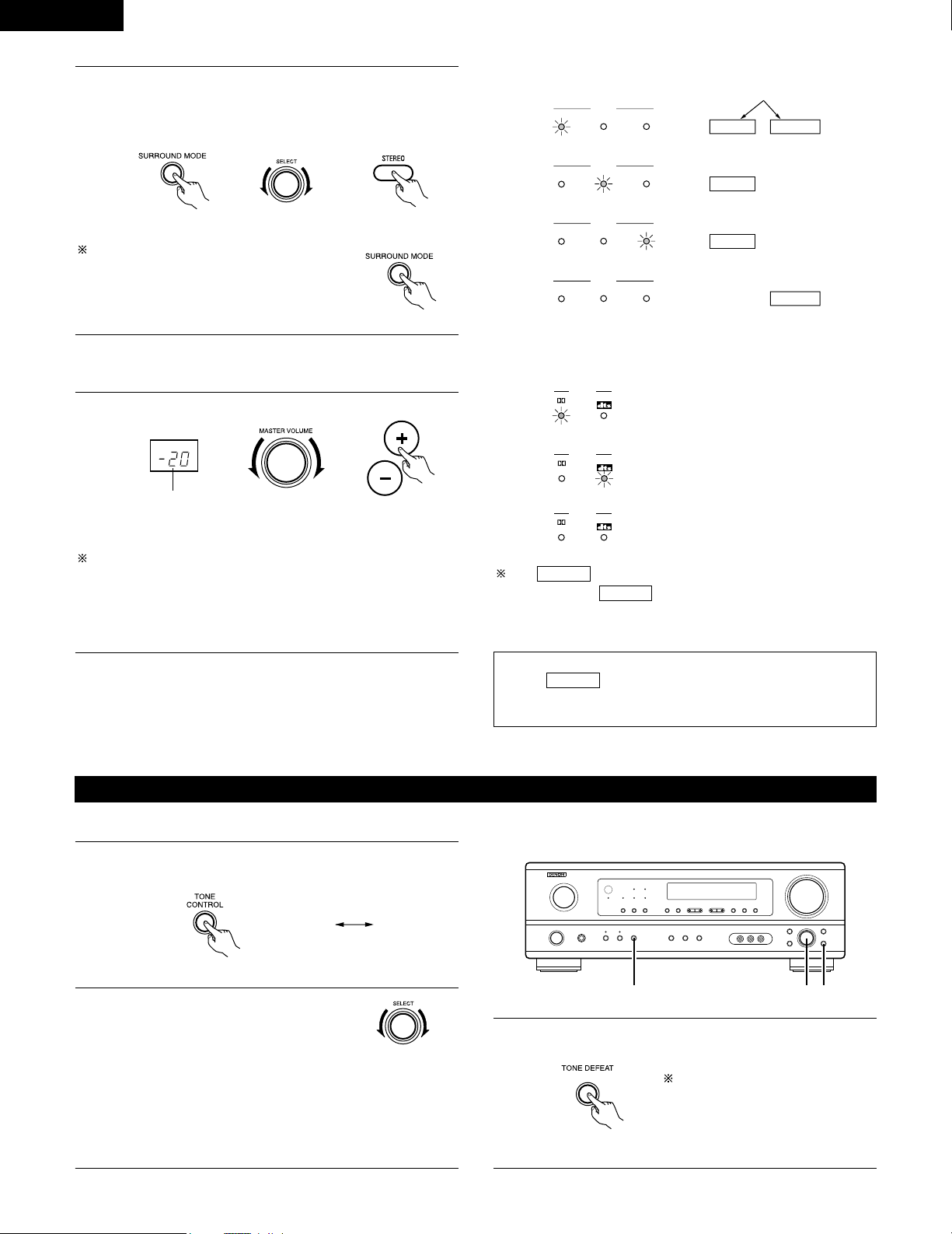
3
Select the play mode.
Press the SURROUND MODE button, then turn the SELECT
knob.
Example: Stereo
(Main unit) (Remote control unit)
4
Start playback on the selected component.
• For operating instructions, refer to the component’s
manual.
5
Adjust the volume.
(Main unit) (Remote control unit)
The volume level is
displayed on the
master volume level
display.
The volume can be adjusted within the range of –60 to 0 to 18 dB,
in steps of 1 dB. However, when the channel level is set as
described on page 32, if the volume for any channel is set at +1 dB
or greater, the volume cannot be adjusted up to 18 dB. (In this case
the maximum volume is adjusted to “18 dB — (Maximum value of
channel level)”.)
Input mode when playing DTS sources
• Noise will be output if DTS-compatible CDs or LDs are played in the
“ANALOG” or “PCM” mode.
When playing DTS-compatible sources, be sure to connect the
source component to the digital input jacks (OPTICAL/COAXIAL)
and set the input mode to “DTS”.
Input mode display
ANALOGDIGITAL
DIGITAL
DIGITAL
ANALOG
AUTO
PCM
DTS
INPUT
AUTO
PCM
DTS
INPUT
AUTO
PCM
DTS
INPUT
AUTO
PCM
DTS
INPUT
• In the AUTO mode
• In the DIGITAL PCM mode
• In the DIGITAL DTS mode
• In the ANALOG mode
One of these lights, depending on the
input signal.
Input signal display
SIGNAL
DIGITAL
DIGITAL
DIGITAL
SIGNAL
SIGNAL
• DOLBY DIGITAL
• DTS
• PCM
The indicator lights when digital signals are being input
properly. If the indicator does not light, check whether
the digital input component setup (page 20) and connections are
correct and whether the component’s power is turned on.
DIGITAL
DIGITAL
NOTE:
• The indicator will light when playing CD-ROMs
containing data other than audio signals, but no sound will be
heard.
DIGITAL
After starting playback
[1] Adjusting the sound quality (tone)
1
The tone switches as follows each time the TONE CONTROL
button is pressed.
BASS TREBLE
2
With the name of the volume to be
adjusted selected, turn the SELECT
knob to adjust the level.
123
(Main unit)
(Main unit)
3
If you do not want the bass and treble to be adjusted, turn on
the tone defeat mode.
The signals do not pass through the
bass and treble adjustment circuits,
so it provides higher quality sound.
(Main unit)
(Main unit)
29
ENGLISH
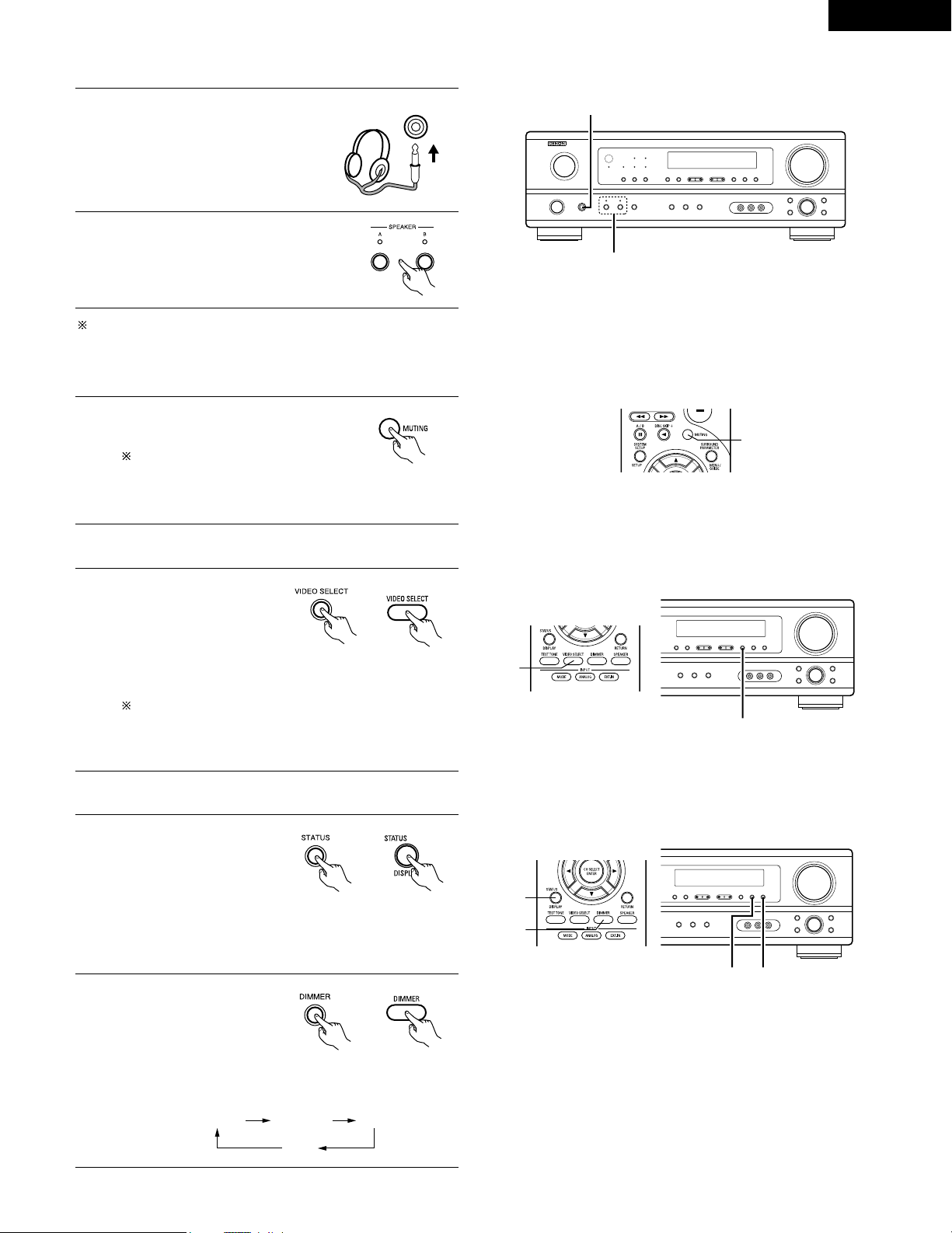
Using the dimmer function
• Use this to change the
brightness of the display.
The display brightness
changes in four steps
(bright, medium, dim and
off) by pressing the main
unit’s DIMMER button repeatedly.
Front panel display
• Descriptions of the unit’s
operations are also
displayed on the front
panel display. In addition,
the display can be
switched to check the
unit’s operating status while playing a source by pressing
the STATUS button.
Simulcast playback
Use this switch to monitor a
video source other than the
audio source.
Press the VIDEO SELECT
button repeatedly until the
desired source appears on
the display.
Cancelling simulcast playback.
• Select “SOURCE” using the video select button.
• Switch the program source to the component
connected to the video input jacks.
[3] Turning the sound off temporarily (muting)
1
Use this to turn off the audio output
temporarily.
Press the MUTING button.
Cancelling MUTING mode.
• Press the MUTING button again.
• Muting will also be cancelled when MASTER VOL is
adjusted up or down.
[4]
Combining the currently playing sound with the desired image
1
[5] Checking the currently playing program source, etc.
1
(Main unit)
(Remote control unit)
1
1
2
2 1
(Main unit)
(Remote control unit)
1
1
2
(Main unit)
BRIGHT MEDIUM
OFF
DIM
(Remote control unit)
[2] Listening over headphones NOTE:
To prevent hearing loss, do not raise the volume level excessively
when using headphones.
2
1
Connect the headphones to the
PHONES jack of the front panel.
1
PHONES
2
Press the SPEAKER A or B button turn
the speaker off.
Caution: No sound is produced from the headphones when
speakers A or B are turned on.
30
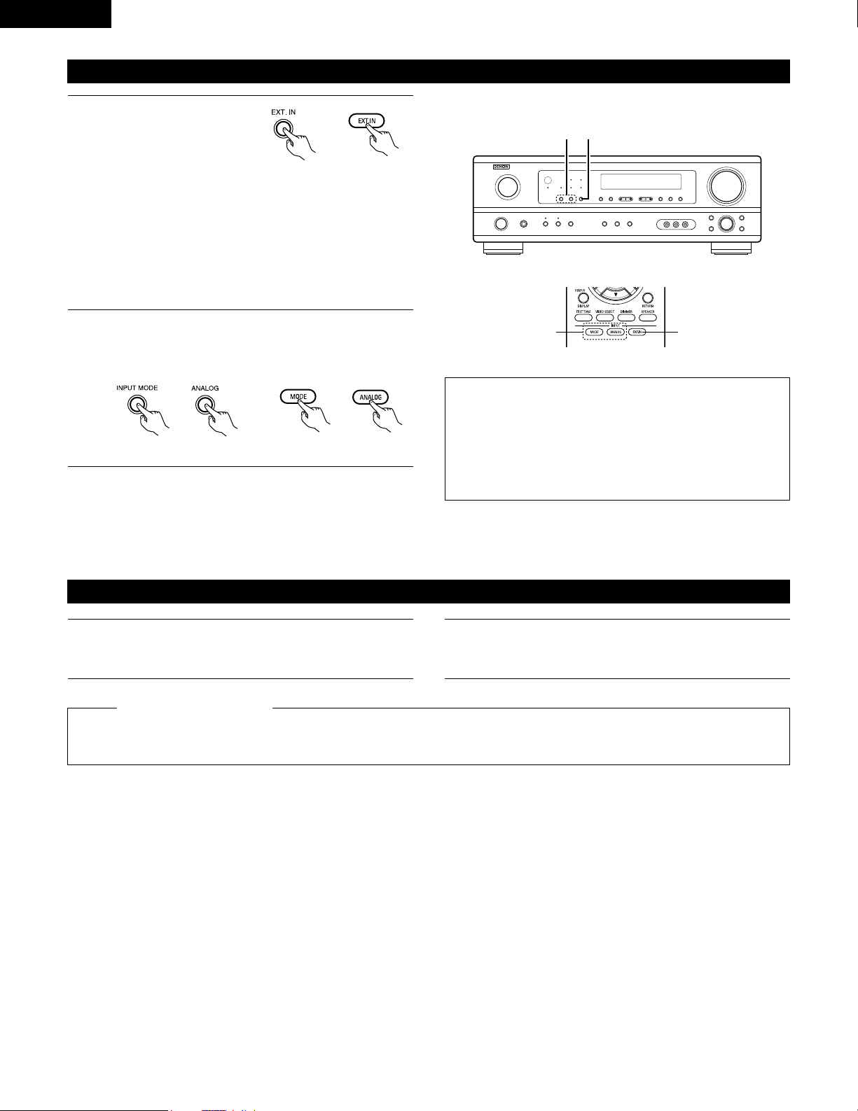
ENGLISH
Set the external input (EXT.
IN) mode.
Press the EXT. IN to switch
the external input.
Once this is selected, the input signals connected to the FL
(front left), FR (front right), C (center), SL (surround left), and
SR (surround right) channels of the EXT. IN jacks are output
directly to the front (left and right), center, surround (left and
right) speaker systems without passing through the surround
circuitry.
In addition, the signal input to the SW (subwoofer) jack is
output to the PRE OUT SUBWOOFER jack.
Playback using the external input (EXT. IN) jacks
1
(Main unit)
(Remote control unit)
2
Cancelling the external input mode
To cancel the external input (EXT. IN) setting, press the INPUT
MODE (AUTO, PCM, DTS) or ANALOG button to switch to
the desired input mode. (See page 27.)
(Remote control unit)
(Main unit)
• When the input mode is set to the external input (EXT. IN), the play
mode (STEREO, DOLBY/DTS SURROUND, 5CH STEREO or DSP
SIMULATION) cannot be selected.
NOTES:
• In play modes other than the external input mode, the signals
connected to EXT. IN jacks cannot be played. In addition, signals
cannot be output from channels not connected to the input
jacks.
• The external input mode can be set for any input source. To
watch video while listening to sound, select the input source to
which the video signal is connected, then set this mode.
2 1
21
Recording the program source (recording the source currently being monitored)
1
Follow step 1 to 3 under “Playing the input source”.
The signals of the source selected with the function selector button are output simultaneously to the CDR/TAPE and VCR REC OUT jacks. If
a total of two tape and/or video decks are connected and set to the recording mode, the same source can be recorded simultaneously on
every decks.
NOTES:
• The AUDIO IN’s signal selected with the function selector button are output to the CDR/TAPE and VCR AUDIO OUT jacks.
• Digital signals are not output from the audio output jack.
2
Start recording on the tape or video deck.
For instructions, refer to the component’s operating
instructions.
Simultaneous recording
31
ENGLISH
13
SURROUND
Before playing with the surround function
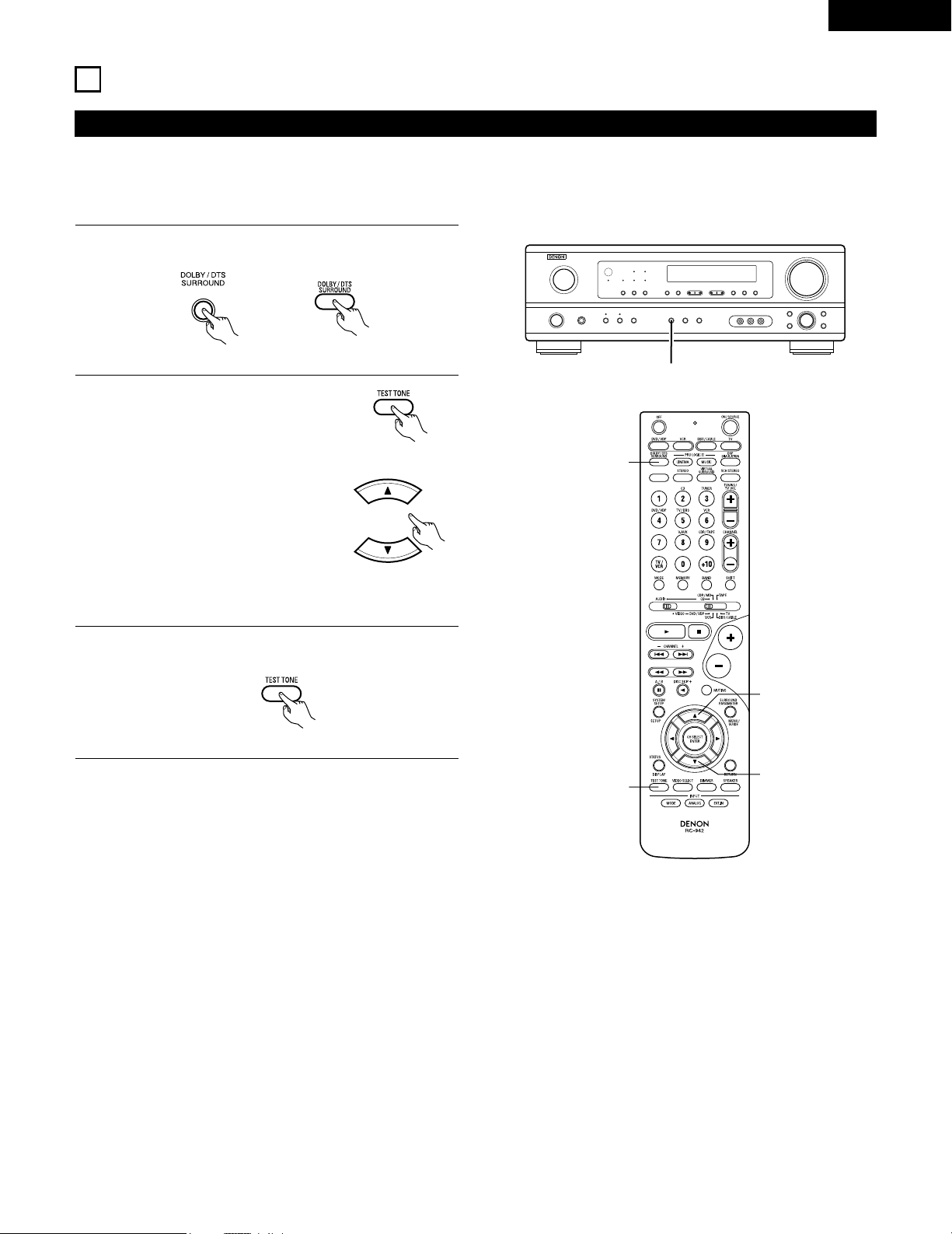
• Before playing with the surround function, be sure to use the test tones to adjust the playback level from each speakers. This adjustment can
be performed from the remote control unit, as (described) below.
• The adjustment with the test tones is only effective in the DOLBY/DTS SURROUND modes.
The adjusted playback levels for the different surround modes are automatically stored in the memory of each surround modes.
1
Set the DOLBY/DTS SURROUND (Dolby Pro Logic II or Dolby
Digital or DTS) modes.
2
Press the TEST TONE button.
3
After completing the adjustment, press the TEST TONE
button again.
(Main unit) (Remote control unit)
(Remote control unit)
Test tones are output from the
different speakers. Use the channel
volume adjust buttons to adjust so
that the volume of the test tones is
the same for all the speakers.
(Remote control unit)
1
2
2
2, 3
1
(Remote control unit)
NOTE: Please make sure the “AUDIO” position of the slide
switch on the remote control unit.
32
ENGLISH
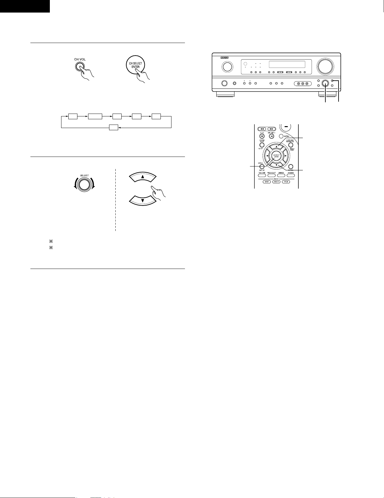
• After adjusting using the test tones, adjust the channel levels either according to the playback sources or to suit your tastes, as (described)
below.
1
Select the speaker whose level you want to adjust.
The channel switches as shown below each time the button
is pressed.
2
Adjust the level of the selected speaker.
FL CNTR FR SR SL
SW
(Main unit) (Remote control unit)
(Main unit)
(Remote control unit)
2 1
2
2
1
NOTE: Please make sure the “AUDIO” position of the slide
switch on the remote control unit.
Default setting of channel level is 0 dB.
The level of the selected speaker can be adjusted within
the range of +12 to –12 dB using the SELECT knob or
cursor buttons.
Only adjustable when the
channel is selected with the
CH VOL buttons on the main
unit.
33
ENGLISH
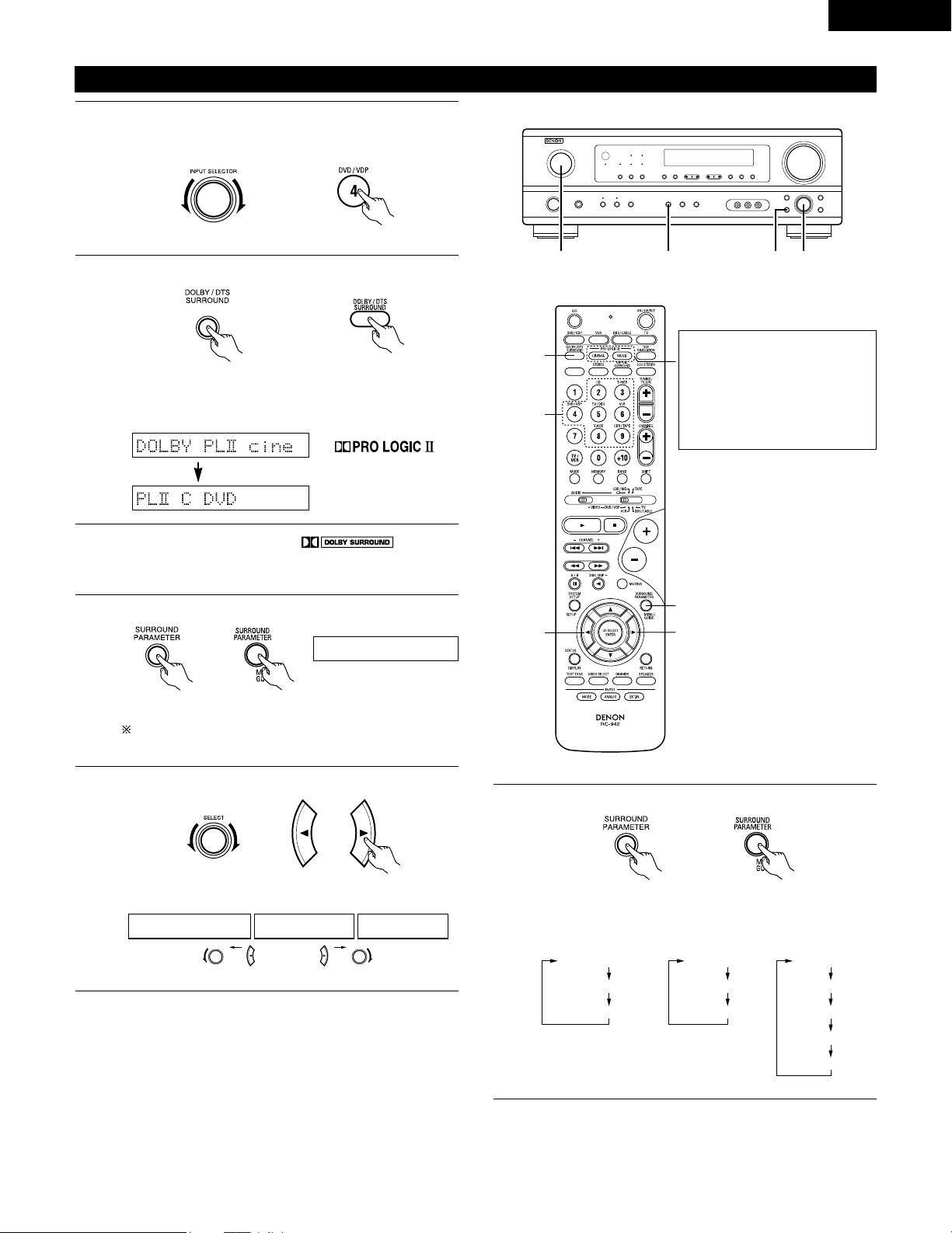
Dolby Surround Pro Logic
II
mode
2
Select the Dolby Surround Pro Logic II mode.
Light
(Main unit)
(Remote control unit)
3
Play a program source with the mark.
• For operating instructions, refer to the manuals of the
respective components.
5, 74, 61 2
4, 6
5, 7
1
5, 7
2
4
Select the surround parameter mode.
MODE Dolby PL
CINEMA EQ
DEFAULT
MODE CINEMA
CINEMA EQ
DEFAULT
MODE MUSIC
PANORAMA
DIMENSION
CENTER WIDTH
DEFAULT
or or
MODE musicMODE cinemaMODE DOLBY PL
1
Select the function to which the component you want to play
is connected.
Example: DVD
(Main unit) (Remote control unit)
Display
(Main unit) (Remote control unit)
To perform this operation from the remote control unit,
check that the mode selector switch is set to “AUDIO”.
MODE cinema
Display
5
Select the optimum mode for the source.
(Main unit) (Remote control unit)
6
Set the surround parameters according to the mode.
(Main unit) (Remote control unit)
• The mode switches as shown below each time the button
is pressed.
• The Dolby Pro Logic indicator lights.
The Dolby Surround Pro Logic II
Cinema or Music mode can be
chosen directly by pressing the
CINEMA or MUSIC button on
the remote control unit during
playback in the Dolby Surround
Pro Logic II mode.
34
ENGLISH
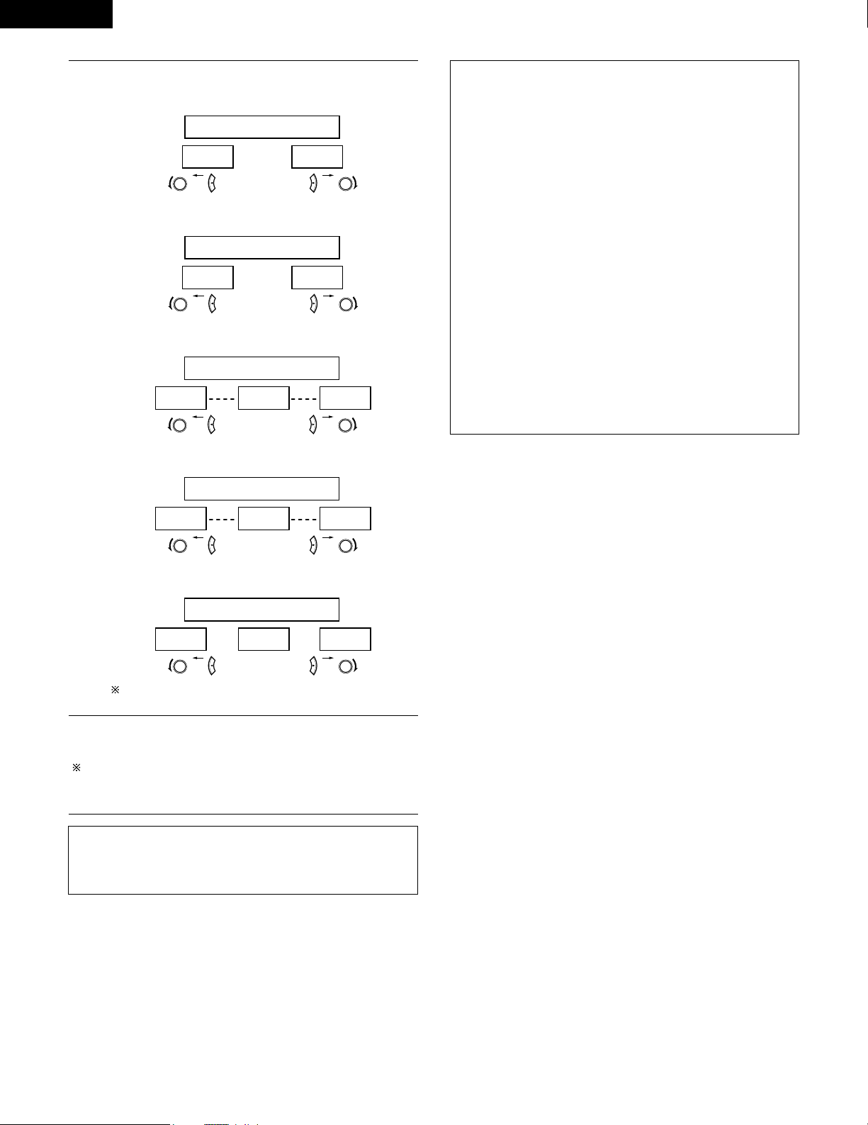
NOTE:
• When making parameter settings, the display will return to the
regular condition several seconds after the last button was
pressed and the setting will be completed.
7
Set the various surround parameters.
• CINEMA EQ setting
ON OFF
or or
CINEMA EQ OFF
• PANORAMA setting
ON OFF
or or
PANORAMA OFF
• DIMENSION setting
0 3 6
or or
DIMENSION 3
• CENTER WIDTH setting
0
CENTER WIDTH 3
4 7
or or
• DEFAULT setting
YES Y/N NO
or or
DEFAULT Y/N
Select “Ye s” to reset to the factory defaults.
Surround parameters q
Pro Logic II Mode:
The Cinema mode is for use with stereo television shows and all
programs encoded in Dolby Surround.
The Music mode is recommended as the standard mode for
autosound music systems (no video), and is optional for A/V
systems.
The Dolby PL mode offers the same robust surround processing
as original Pro Logic in case the source contents is not of optimum
quality.
Select one of the modes (“Cinema”, “Music” or “Dolby PL”).
Panorama Control:
This mode extends the front stereo image to include the surround
speakers for an exciting “wraparound” effect with side wall
imaging.
Select “OFF” or “ON”.
Dimension Control:
This control gradually adjust the soundfield either towards the front
or towards the rear.
The control can be set in 7 steps from 0 to 6.
Center Width Control:
This control adjust the center image so it may be heard only from
the center speaker; only from the left/right speakers as a phantom
image; or from all three front speakers to varying degrees.
The control can be set in 8 steps from 0 to 7.
Stop pressing buttons once you have completed setting the
surround parameters. After several seconds the normal display
reappears and the settings you have made are automatically set.
Press the surround parameter button to switch to the CINEMA EQ,
PANORAMA setting.
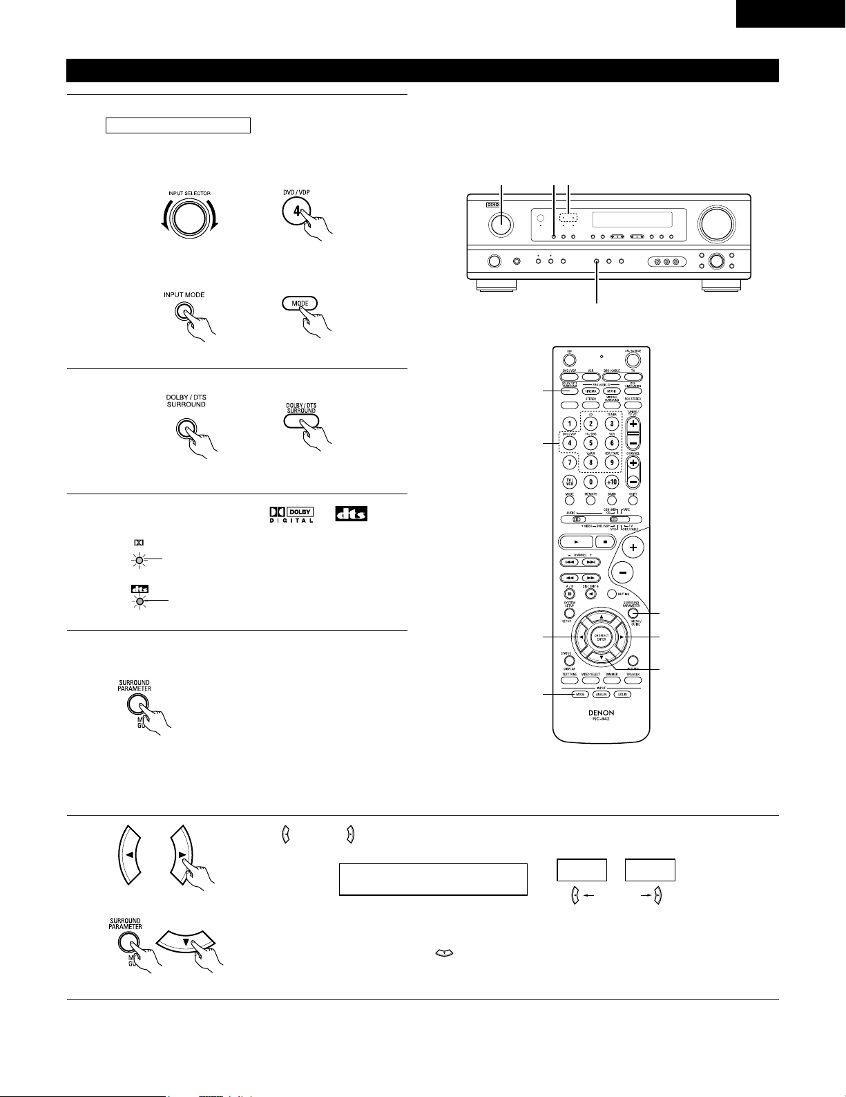
35
ENGLISH
Dolby Digital mode (only with digital input) and DTS Surround (only with digital input)
1
Select the input source.
q Select an input source set to digital (COAXIAL/OPTICAL)
(see page 20).
(Main unit) (Remote control unit)
w Set the input mode to “AUTO” or DTS.
2
Select the Dolby/DTS Surround mode.
(Remote control unit)
3
Play a program source with the , mark.
• The Dolby Digital indicator lights when
playing Dolby Digital sources.
DIGITAL
Light
2
1 1 3
4, 5, 6, 7, 8
5, 6, 7, 8
5, 6, 7, 8
5, 6, 7, 8
1
1
2
Playback with a digital input
• The DTS indicator lights when playing
DTS sources.
Light
4
Set the surround parameter according to the source.
First, press the SURROUND PARAMETER button.
(Remote control unit)
NOTE:
Please make sure the “AUDIO” position of the slide switch
on the remote control unit.
Press the SURROUND PARAMETER or (down) button to switch to the D. COMP. setting.
Use the (left) and (right) buttons to set the CINEMA EQ.
5
Example: DVD
(Main unit) (Remote control unit)
CINEMA EQ OFF
ON
OFF
(left) button (right) button
(Initial)
(Remote control unit)
(Remote control unit)
(Main unit)
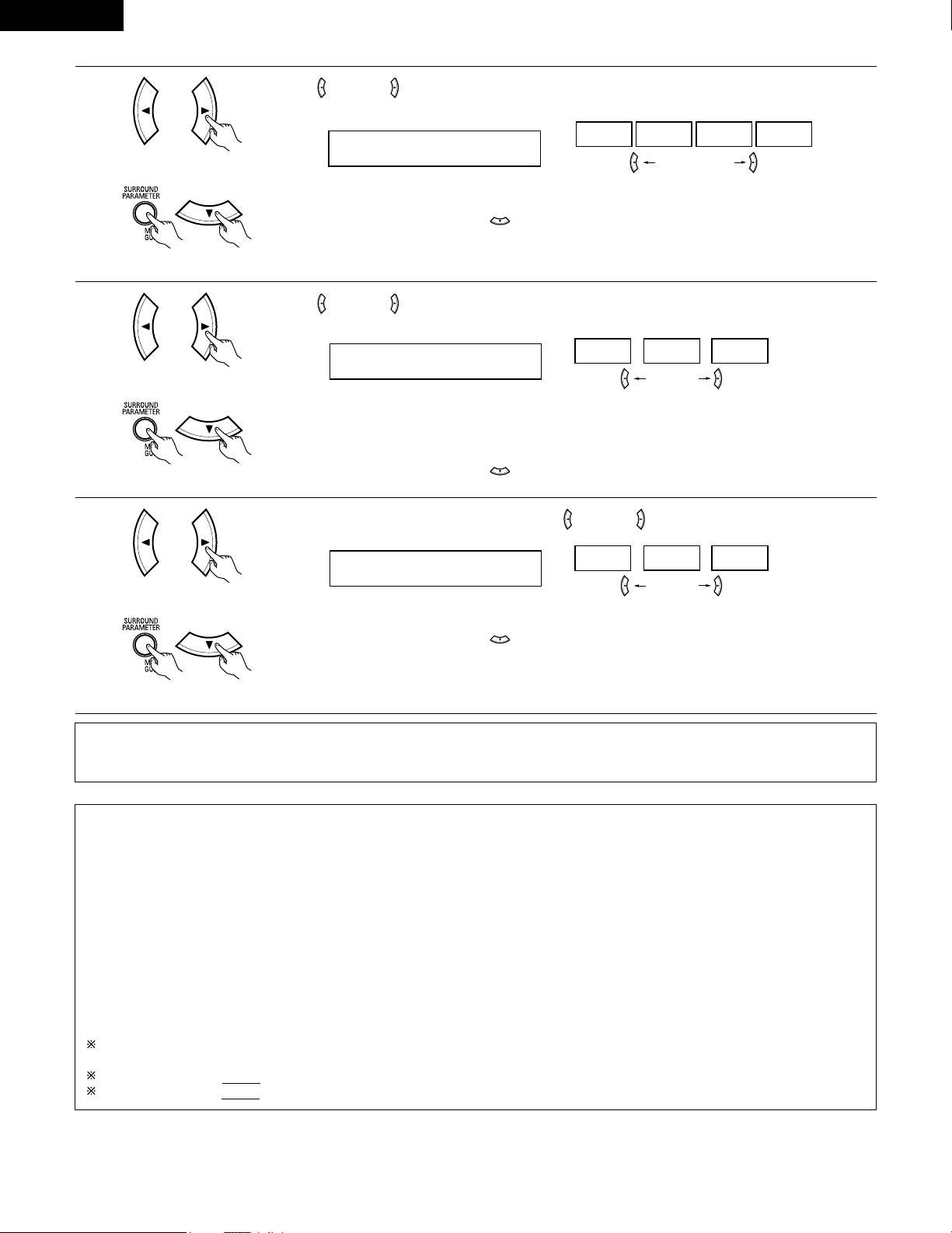
36
ENGLISH
6
Use the (left) and (right) buttons to set the D. COMP.
D.COMP. OFF
OFF LOW MID HIGH
Press the SURROUND PARAMETER or (down) button to switch to the LFE setting.
(left) button (right) button
(Remote control unit)
(Remote control unit)
7
Use the (left) and (right) buttons to set the LFE level.
LFE 0dB
-10dB
-5dB 0dB
• The level can be adjusted in units of 1 dB from –10 to 0 dB.
Set to the desired level according to the speaker systems being used and the source to be played.
Press the SURROUND PARAMETER or (down) button to switch to the default setting.
(Remote control unit)
(Remote control unit)
NOTE:
This parameter is not displayed during DTS playback.
8
To reset the settings to the factory defaults, use the (left) and (right) buttons to display “Yes”.
DEFAULT Y/N
YES
Y/N NO
Press the SURROUND PARAMETER or (down) button to switch to the CINEMA EQ. setting.
(left) button (right) button
(Remote control unit)
(Remote control unit)
Surround parameters w
CINEMA EQ. (Cinema Equalizer):
The Cinema EQ function gently decreases the level of the extreme high frequencies, compensating for overly-bright sounding motion picture
soundtracks. Select this function if the sound from the front speakers is too bright.
This function only works in the Dolby Pro Logic, Dolby Digital and DTS Surround modes. (The same contents are set for all operating modes.)
D.COMP. (Dynamic Range Compression):
Motion picture soundtracks have tremendous dynamic range (the contrast between very soft and very loud sounds). For listening late at night,
or whenever the maximum sound level is lower than usual, the Dynamic Range Compression allows you to hear all of the sounds in the
soundtrack (but with reduced dynamic range). (This only works when playing program sources recorded in Dolby Digital.) Select one of the four
parameters (“OFF”, “LOW”, “MID” (middle) or “HIGH” (high)). Set to OFF for normal listening.
LFE (Low Frequency Effect):
Program source and adjustment range
1. Dolby Digital: –10 dB to 0 dB
2. DTS Surround: –10 dB to 0 dB
When Dolby Digital encoded software is played, it is recommended that the LFE LEVEL be set to 0 dB for correct Dolby Digital
playback.
When DTS encoded movie software is played, it is recommended that the LFE LEVEL be set to 0 dB for correct DTS playback.
When DTS encoded music software is played, it is recommended that the LFE LEVEL be set to -10 dB for correct DTS playback.
(Initial)
(Initial)
(left) button (right) button
NOTE:
• When making parameter settings, the display will return to the regular condition several seconds after the last button was pressed and the
setting will be completed.
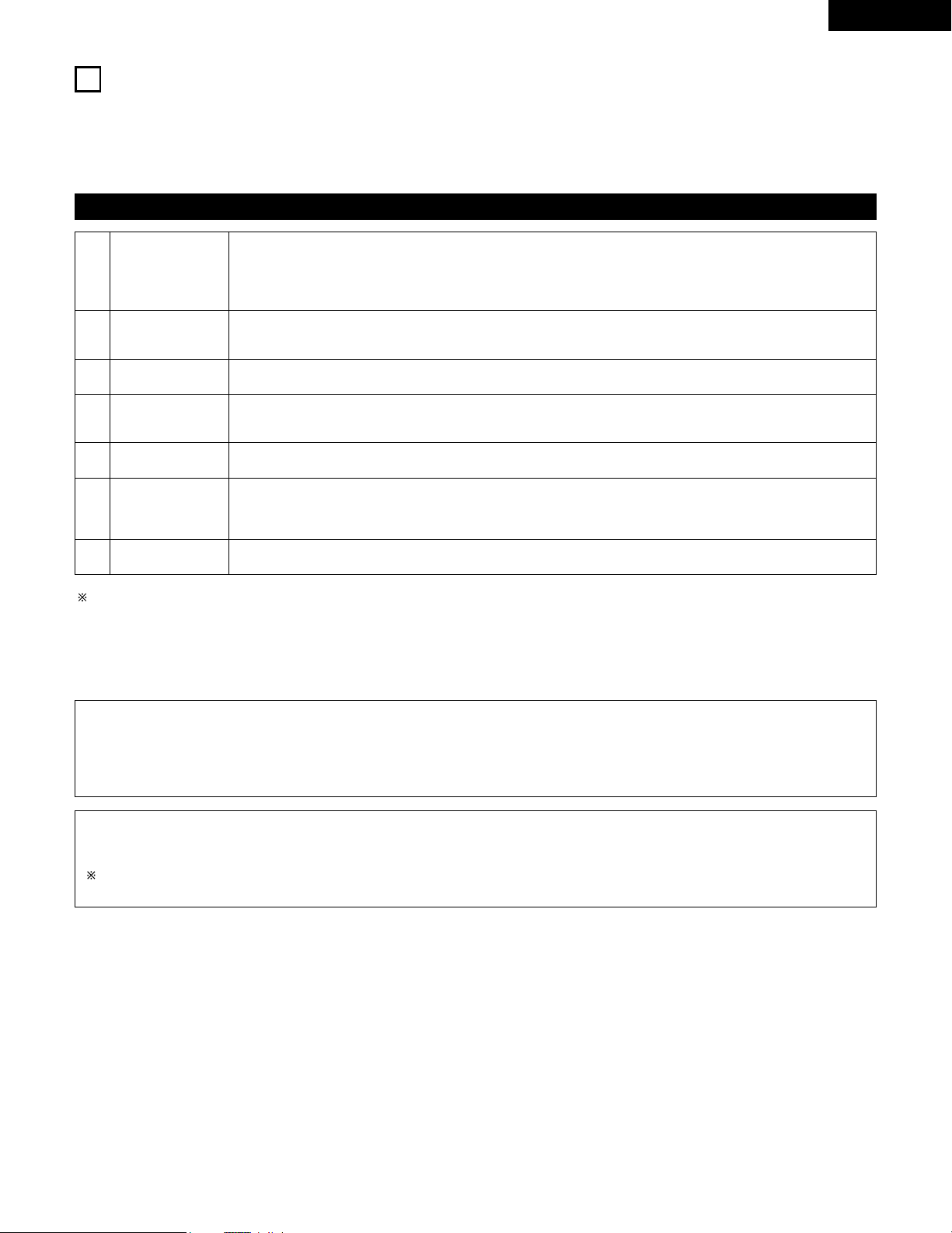
37
ENGLISH
14
DSP SURROUND SIMULATION
• This unit is equipped with a high performance DSP (Digital Signal Processor) which uses digital signal processing to synthetically recreate the
sound field. One of 7 preset surround modes can be selected according to the program source and the parameters can be adjusted according
to the conditions in the listening room to achieve a more realistic, powerful sound. These surround modes can also be used for program sources
not recorded in Dolby Surround Pro Logic or Dolby Digital.
Surround modes and their features
1
2
3
4
5
6
7 VIRTUAL
ROCK ARENA
JAZZ CLUB
VIDEO GAME
MONO MOVIE
(NOTE 1)
MATRIX
5CH STEREO
Select this mode to enjoy a virtual sound field, produced from the front 2-channel speakers.
Use this mode to achieve the feeling of a live concert in an arena with reflected sounds coming from all directions.
This mode creates the sound field of a live house with a low ceiling and hard walls. This mode gives jazz a very
vivid realism.
Use this to enjoy video game sources.
Select this when watching monaural movies for a greater sense of expansion.
Select this to emphasize the sense of expansion for music sources recorded in stereo. Signals consisting of the
difference component of the input signals (the component that provides the sense of expansion) processed for
delay are output from the surround channel.
In this mode, the signals of the front left channel are output from the left surround channel, the signals of the front
right channel are output from the right surround channel, and the same (in-phase) component of the left and right
channels is output from the center channel. This mode provides all speaker surround sound, but without directional
steering effects, and works with any stereo program source.
Depending on the program source being played, the effect may not be very noticeable.
In this case, try other surround modes, without worrying about their names, to create a sound field suited to your tastes.
NOTE 1: When playing sources recorded in monaural, the sound will be one-sided if signals are only input to one channel (left or right), so input
signals to both channels. If you have a source component with only one audio output (monophonic camcorder, etc.) obtain a “Y” adaptor
cable to split the mono output to two outputs, and connect to the L and R inputs.
Personal Memory Plus
This set is equipped with a personal memorize function that automatically memorizes the surround modes and input modes selected for the
input different sources. When the input source is switched, the modes set for that source last time it was used are automatically recalled.
The surround parameters, tone control settings and playback level balance for the different output channels are memorized for each
surround mode.
NOTE:
Only the STEREO mode can be used when playing PCM signals with a sampling frequency of 96 kHz (such as from DVD-Video discs that
contain 24 bit, 96 kHz audio). If such signals are input during playback in one of the other surround modes, the mode automatically switches
to STEREO.
If the DTS signals are input during playback in VIRTUAL surround mode, the mode automatically switches to STEREO.
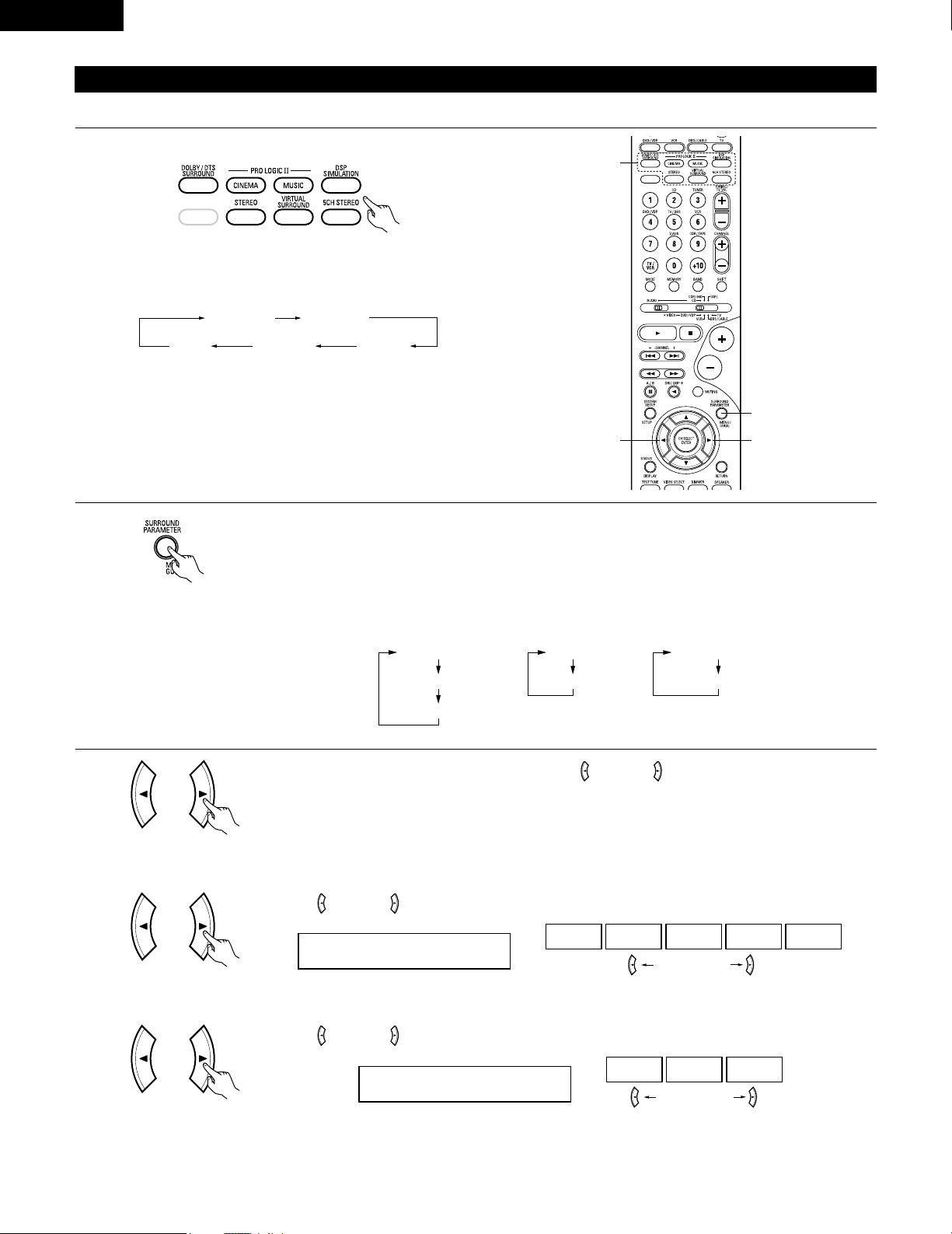
38
ENGLISH
DSP surround simulation
1
Select the surround mode for the input channel.
(Remote control unit)
The surround mode switches in the following order each time
the DSP SIMULATION button is pressed:
2
33
1
2
To enter the surround parameter setting mode, press the SURROUND PARAMETER button.
• The surround parameter switches in the following order each time the SURROUND PARAMETER button is
pressed for the different surround modes.
MONO MOVIE ROCK ARENA
JAZZ CLUBVIDEO GAME
MATRIX
• To operate the surround mode and surround parameters from the remote control unit.
(Remote control unit)
3
Use the (left) and (right) buttons to set the room size.
ROOM SIZE MED
LARGEMED-LMEDMED-SSMALL
(left) button (right) button
(Remote control unit)
(1) ROOM SIZE
Display the parameter you want to adjust, then use the (left) and (right) buttons to set it.
ROOM SIZE
EFFECT
DEFAULT
EFFECT LEVEL
DEFAULT
DELAY
DEFAULT
• ROCK ARENA
• JAZZ CLUB
• VIDEO GAME
• MONO MOVIE
• MATRIX • VIRTUAL
(Initial)
Use the (left) and (right) buttons to set the effect level.
EFFECT LEVEL 10
15101
(left) button (right) button
(Remote control unit)
(2) EFFECT LEVEL
(Initial)
(Remote control unit)
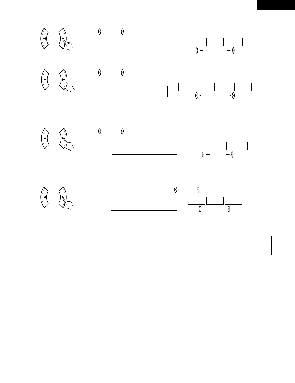
39
ENGLISH
Use the (left) and (right) buttons to set the delay time.
DELAY 30ms
110ms30ms0ms
(left) button (right) button
(Remote control unit)
(3) DELAY TIME
(Remote control unit)
(6) DEFAULT
To reset the settings to the factory defaults, use the (left) and (right) buttons to display “Yes”.
DEFAULT Y/N
NOY/NYES
(left) button (right) button
(Initial)
Use the (left) and (right) buttons to set the D. COMP.
D.COMP. OFF
OFF LOW MID HIGH
(left) button (right) button
(Remote control unit)
NOTE:
This parameter is displayed during DOLBY DIGITAL playback.
(Initial)
(4) D. COMP.
Use the (left) and (right) buttons to set the LFE.
LFE 0dB
-10dB
-5dB 0dB
(left) button (right) button
(Remote control unit)
NOTE:
This parameter is displayed during DOLBY DIGITAL playback.
(Initial)
(5) LFE
NOTE:
• When making parameter settings, the display will return to the regular condition several seconds after the last button was pressed and the
setting will be completed.
Press the surround parameter button to switch to the ROOM SIZE, DELAY, EFFECT LEVEL setting.
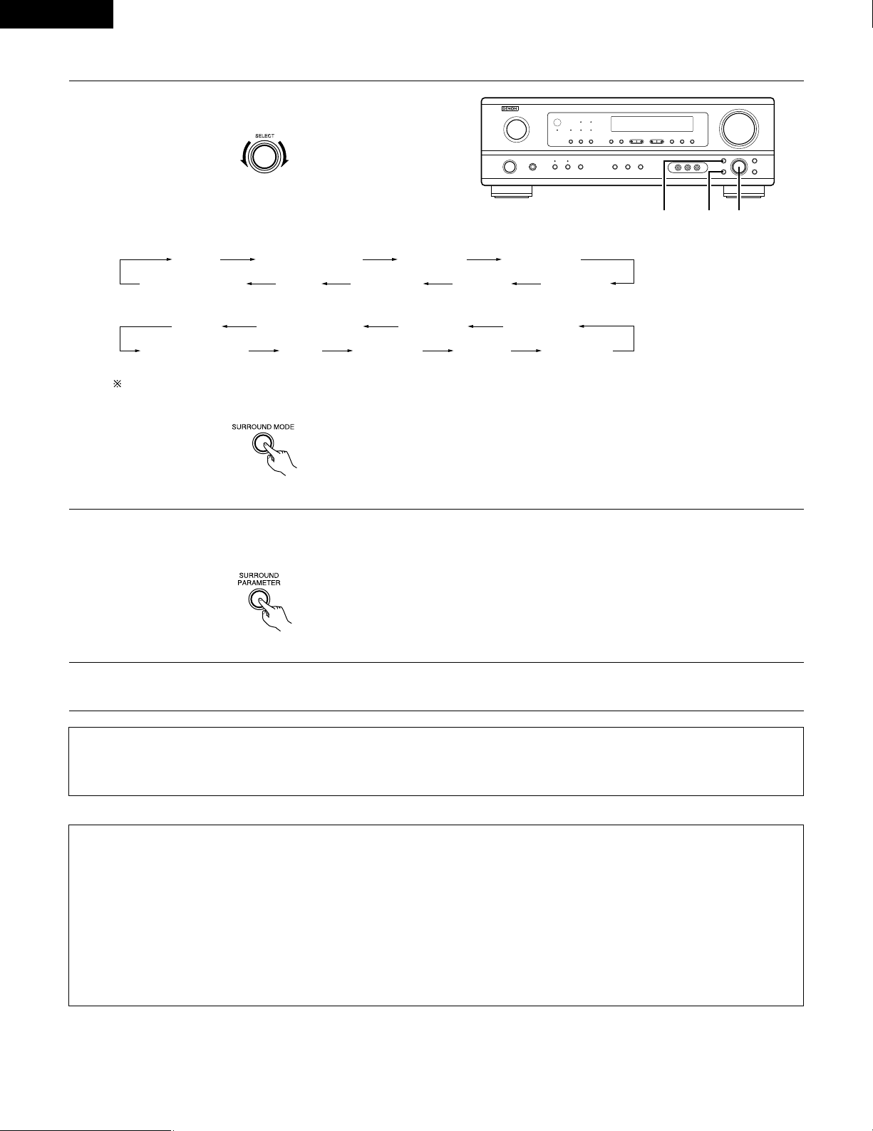
40
ENGLISH
1
Turn the SELECT knob to select the surround mode.
(Main unit)
• When turned clockwise
2
Press the SURROUND PARAMETER button.
Press and hold in the surround parameter button to select the parameter you want to set.
• The parameters which can be set differ for the different surround modes. (Refer to “Surround Modes and Parameters” on page 41.
STEREO DOLBY PRO LOGIC II
5CH STEREO
MONO MOVIE
JAZZ CLUB ROCK ARENAVIDEO GAMEMATRIXVIRTUAL SURROUND
STEREO DOLBY PRO LOGIC II
5CH STEREO
MONO MOVIE
JAZZ CLUB ROCK ARENAVIDEO GAMEMATRIXVIRTUAL SURROUND
• Operating the surround mode and surround parameters from the main unit‘s panel.
1, 321
• When turned counterclockwise
To select the surround mode while adjusting the surround parameters, channel volume or tone control, press the SURROUND MODE
button then operate the selector.
(Main unit)
(Main unit)
3
Display the parameter you want to adjust, then turn the SELECT knob to set it.
NOTE:
• When playing PCM digital signals or analog signals in the 5CH STEREO, ROCK ARENA, JAZZ CLUB, VIDEO GAME, MONO MOVIE or
MATRIX surround modes and the input signal switches to a digital signal encoded in Dolby Digital, the Dolby surround mode switches
automatically. When the input signal switches to a DTS signal, the mode automatically switches to DTS surround.
Surround parameters e
ROOM SIZE:
This sets the size of the sound field.
There are five settings: “small”, “med.s” (medium-small), “medium”, “med.l” (medium-large) and “large”. “small” recreates a small sound
field, “large” a large sound field.
EFFECT LEVEL:
This sets the strength of the surround effect.
The level can be set in 15 steps from 1 to 15. When the surround mode is set to “VIRTUAL”, the effect level can be set in steps from 1 to 10.
Lower the level if the sound seems distorted.
DELAY TIME:
In the matrix mode only, the delay time can be set within the range of 0 to 110 ms.
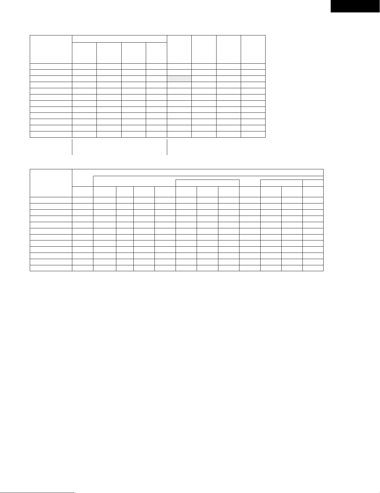
41
ENGLISH
C
E
C
*
C
E
E
E
E
E
E
E
C
2 Surround modes and parameters
Channel output
B
B
B
B
B
B
B
B
B
B
B
B
SUB-
WOOFER
E
B
B
B
B
B
B
B
B
B
B
E
SURROUND
L/R
E
B
B
B
B
B
B
B
B
B
B
E
CENTER
C
C
C
C
C
C
C
C
C
C
C
C
FRONT L/R
Mode
STEREO
EXTERNAL INPUT
DOLBY PRO LOGIC
II
DOLBY DIGITAL
DTS SURROUND
5CH STEREO
ROCK ARENA
JAZZ CLUB
VIDEO GAME
MONO MOVIE
MATRIX
VIRTUAL
C : Signal
E : No signal
B : Turned on or off by speaker configuration setting
When
playing
Dolby
Digital
signals
When
playing
DTS
signals
C
E
E
E
C
E
E
E
E
E
E
C
Parameter (default values are shown in parentheses)
Dolby Digital signals
D.COMP.
C (OFF)
E
C (OFF)
C (OFF)
E
E
E
E
E
E
E
C (OFF)
E
E
E
E
E
E
E
E
E
E
C
(30msec)
E
DELAY
TIME
E
E
E
E
E
E
C (10)
C (10)
C (10)
C (10)
E
C (10)
EFFECT
LEVEL
E
E
E
E
E
E
C
(Medium)
C
(Medium)
C
(Medium)
C
(Medium)
E
E
ROOM
SIZE
C (0dB)
C (0dB)
C (0dB)
C (0dB)
C (0dB)
C (0dB)
C (0dB)
C (0dB)
C (0dB)
C (0dB)
C (0dB)
C (0dB)
TONE
CONTROL
Mode
STEREO
EXTERNAL INPUT
DOLBY PRO LOGIC
II
DOLBY DIGITAL
DTS SURROUND
5CH STEREO
ROCK ARENA
JAZZ CLUB
VIDEO GAME
MONO MOVIE
MATRIX
VIRTUAL
C : Adjustable
E : Not adjustable
LFE
C (0dB)
E
C (0dB)
C (0dB)
–
E
E
E
E
E
E
C (0dB)
When
playing
PCM
signals
(96k)
C ( C )
E
C
E
E
C
C
C
C
C
C
C
When
playing
ANALOG
signals
C
C
C
E
E
C
C
C
C
C
C
C
C : Able
E : Unable
E
E
C
(CINEMA)
E
E
E
E
E
E
E
E
E
MODE
E
E
C (OFF)
E
E
E
E
E
E
E
E
E
PANORAMA
E
E
C (3)
E
E
E
E
E
E
E
E
E
DIMENSION
E
E
C (0)
E
E
E
E
E
E
E
E
E
CENTER
WIDTH
E
E
C (OFF)
C (OFF)
C (OFF)
E
E
E
E
E
E
E
CINEMA
EQ
LFE
C (0dB)
E
–
–
C (0dB)
E
E
E
E
E
E
E
DTS signals
PRO LOGIC II MUSIC MODE ONLY
SURROUND PARAMETER
* Only for 2 ch contents.
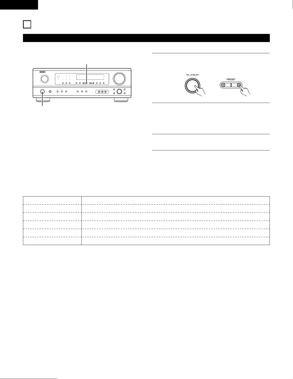
42
ENGLISH
15
LISTENING TO THE RADIO
Auto preset memory
1
When the main unit’s power operation switch turn on while
pressing the set’s PRESET
DD
button the unit automatically
begins searching for FM broadcast stations.
2
When the first FM broadcast station is found, that station is
stored in the preset memory at channel A1. Subsequent
stations are automatically stored in order at preset channels
A2 to A8, B1 to B8, C1 to C8, D1 to D8 and E1 to E8, for a
maximum of 40 stations.
3
Channel A1 is tuned in after the auto preset memory
operation is completed.
NOTES:
• If an FM station cannot be preset automatically due to poor
reception, use the “Manual tuning” operation to tune in the
station, then preset it using the manual “Preset memory”
operation.
• To interrupt this function, press the power operation button.
1
1
This unit is equipped with a function for automatically searching for FM broadcast stations and storing them in the preset memory.
2 DEFAULT VALUE
AUTO TUNER PRESETS
A1 ~ A8 87.5/89.1/98.1/107.9/90.1/90.1/90.1/90.1 MHz
B1 ~ B8 520/600/1000/1400/1500/1710 kHz/90.1/90.1 MHz
C1 ~ C8 90.1 MHz
D1 ~ D8 90.1 MHz
E1 ~ E8 90.1 MHz
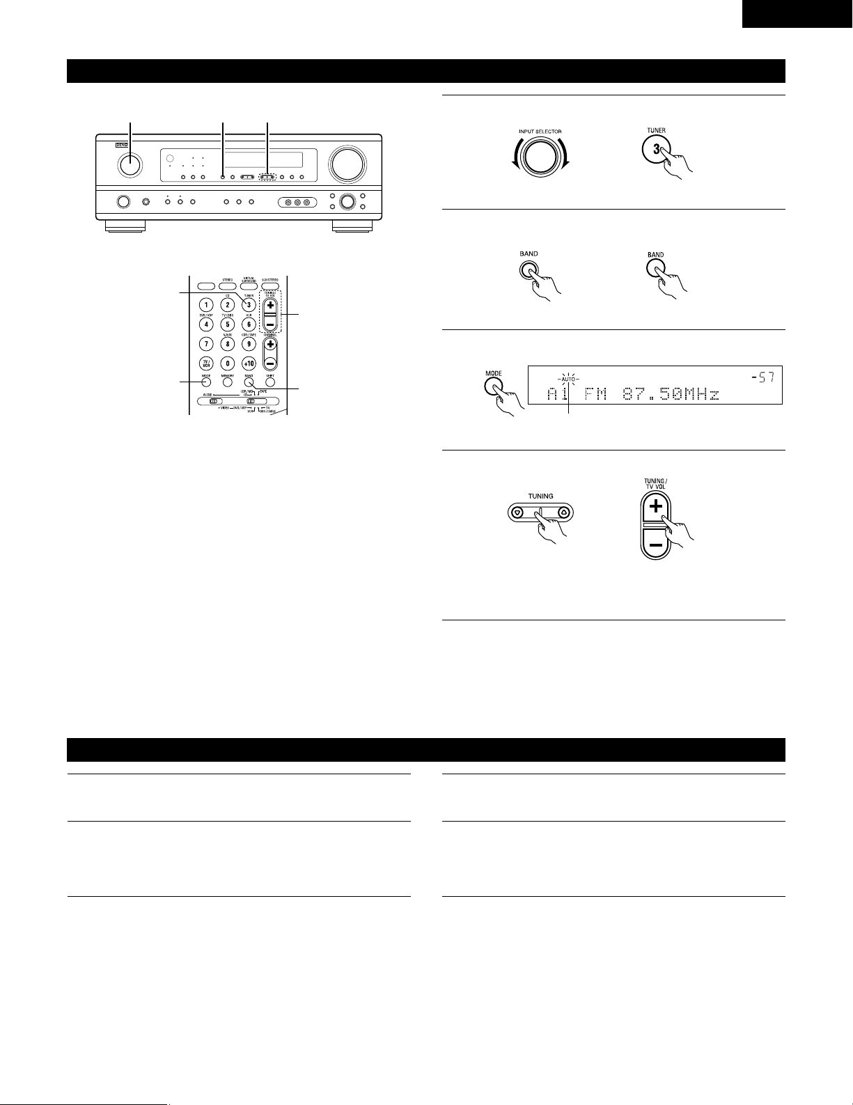
43
ENGLISH
Press the TUNING
DD
(+) or
HH
(–) button to tune in the desired
station.
The frequency changes continuously when the button is held
in.
Auto tuning
1
Set the input source to “TUNER”.
2
Watching the display, press the BAND button to select the
desired band (AM or FM).
3
Press the MODE button to set the auto tuning mode.
Lit
4
Press the TUNING
DD
(+) or
HH
(–) button.
• Automatic searching begins, then stops when a station is
tuned in.
NOTE:
• When in the auto tuning mode on the FM band, the “STEREO”
indicator lights on the display when a stereo broadcast is tuned in.
At open frequencies, the noise is muted and the “TUNED” and
“STEREO” indicators turn off.
2 41
Manual tuning
1
Set the input function to “TUNER”.
2
Watching the display, press the BAND button to select the
desired band (AM or FM).
3
Press the MODE button to set the manual tuning mode.
Check that the display’s “AUTO” indicator turns off.
4
NOTE:
• When the manual tuning mode is set, FM stereo broadcasts are received in monaural and the “STEREO” indicator turns off.
3
1
4
2
(Remote control unit)
(Main unit)
(Main unit) (Remote control unit)
(Remote control unit)(Main unit)
(Remote control unit)
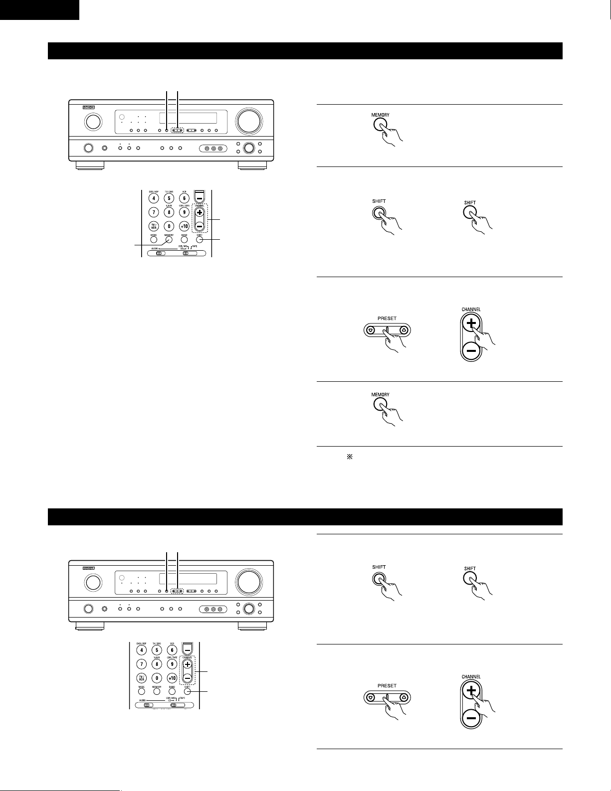
44
ENGLISH
Preset stations
1
Press the MEMORY button.
2
Press the SHIFT button and select the desired memory block
(A to E).
(Main unit) (Remote control unit)
3
Press the PRESET
DD
(+) or
HH
(–) button to select the desired
preset channel (1 to 8).
(Main unit) (Remote control unit)
4
Press the MEMORY button again to
store the station in the preset
memory.
To preset other channels, repeat steps 1 to 4.
A total of 40 broadcast stations can be preset – 8 stations
(channels 1 to 8) in each of blocks A to E.
32
1, 4
3
2
Recalling preset stations
Preparations:
Use the “Auto tuning” or “Manual tuning” operation to tune in the
station to be preset in the memory.
(Remote control unit)
(Remote control unit)
1
Watching the display, press the SHIFT button to select the
preset memory block.
(Main unit) (Remote control unit)
2
Watching the display, press the PRESET
DD
(+) or
HH
(–) button
to select the desired preset channel.
(Main unit) (Remote control unit)
21
2
1
NOTE: Please make sure the “AUDIO” position of the slide
switch on the remote control unit.
NOTE: Please make sure the “AUDIO” position of the slide
switch on the remote control unit.
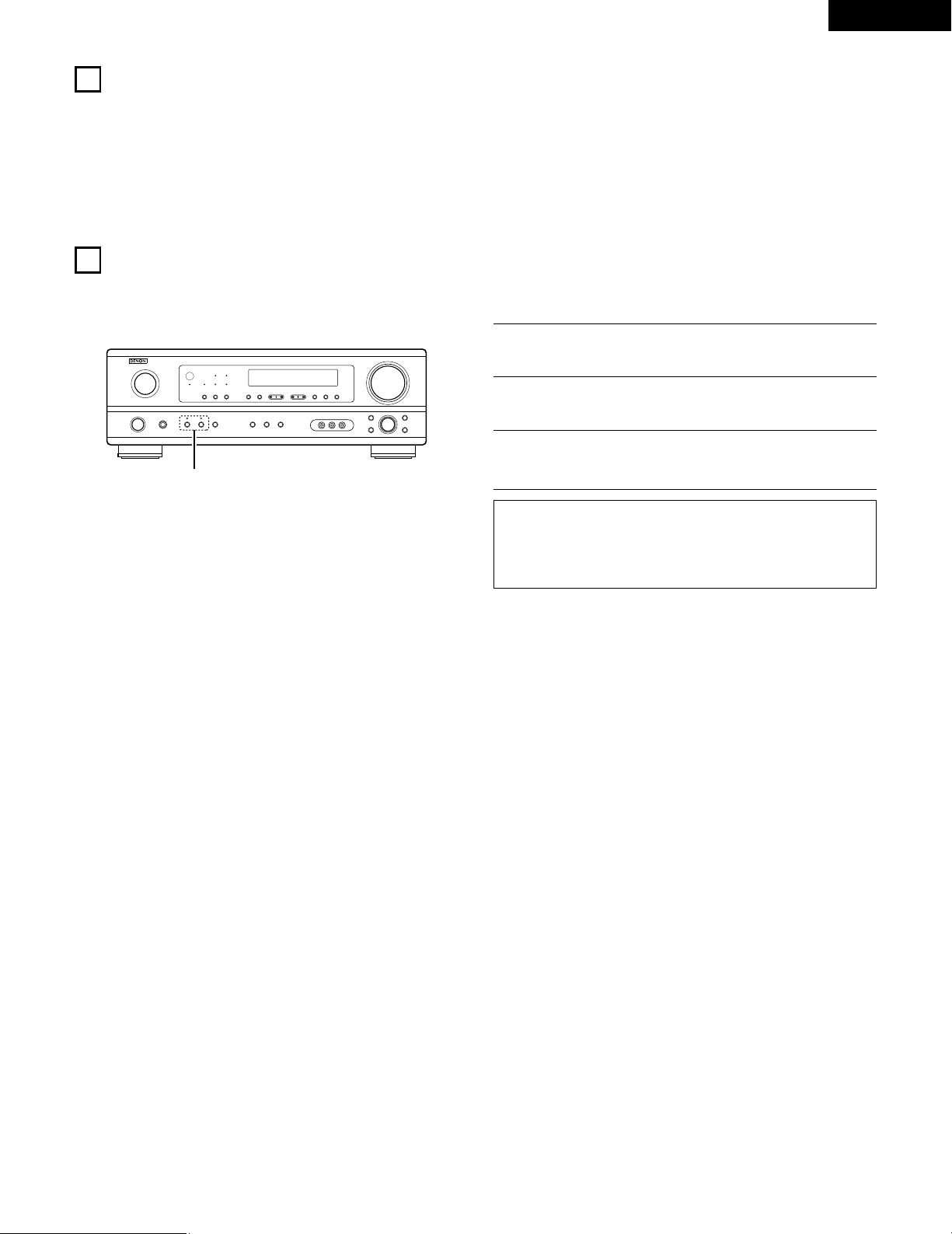
45
ENGLISH
16
LAST FUNCTION MEMORY
• This unit is equipped with a last function memory which stores the input and output setting conditions as they were immediately before the
power is switched off.
• The unit is also equipped with a back-up memory. This function provides approximately one week of memory storage when the main unit’s
power switch is off and with the power cord disconnected.
17
INITIALIZATION OF THE MICROPROCESSOR
When the indication of the display is not normal or when the operation of the unit does not shows the reasonable result, the initialization of the
microprocessor is required by the following procedure.
1
Switch off the unit and remove the AC cord from the wall
outlet.
2
Hold the following SPEAKER A button and B button, and plug
the AC cord into the outlet.
3
Check that the entire display is flashing with an interval of
about 1 second, and release your fingers from the 2 buttons
and the microprocessor will be initialized.
NOTES:
• If step 3 does not work, start over from step 1.
• If the microprocessor has been reset, all the button settings are
reset to the default values (the values set upon shipment from
the factory).
2
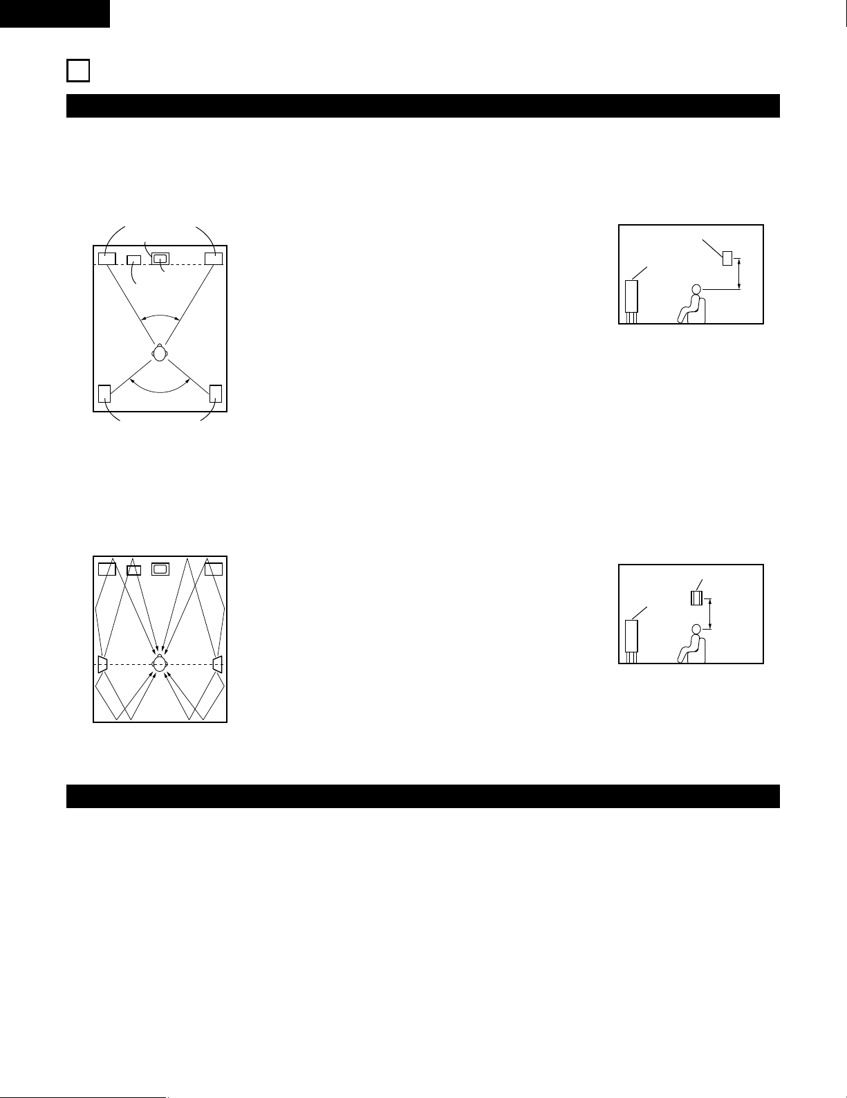
46
ENGLISH
18
ADDITIONAL INFORMATION
• Set the front speakers, center speaker and subwoofer in the
same positions as in example (1).
• Set the surround speakers directly at the sides of the listening
position and 60 to 90 centimeters (2 to 3 feet) above ear level.
• The signals from the surround channels reflect off the walls as
shown on the diagram at the left, creating an enveloping and
realistic surround sound presentation.
• Set the front speakers with their front surfaces as flush with the
TV or monitor screen as possible. Set the center speaker
between the front left and right speakers and no further from
the listening position than the front speakers.
• Consult the owner’s manual for your subwoofer for advice on
placing the subwoofer within the listening room.
• If the surround speakers are direct-radiating (monopolar) then
place them slightly behind and at an angle to the listening
position and parallel to the walls at a position 60 to 90
centimeters (2 to 3 feet) above ear level at the prime listening
position.
Speaker setting examples
Here we describe a number of speaker settings for different purposes. Use these examples as guides to set up your system according to the type
of speakers used and the main usage purpose.
(1) Basic setting
Use this setting if your main purpose is to listen to movie music and when using one set (two speakers) of regular single-way or two-way
speakers as the surround speakers.
(2) Using diffusion type speakers for the surround speakers
For the greatest sense of surround sound envelopment, diffuse radiation speakers such as bipolar types, or dipolar types, provide a wider
dispersion than is possible to obtain from a direct radiating speaker (monopolar). Place these speakers at either side of the prime listening
position, mounted above ear level.
Subwoofer
Surround speaker
Front speaker
60 to 90 cm
Surround speaker
Front speaker
60 to 90 cm
Surround speakers
120°
Front speakers
45°
Monitor
Center speaker
As seen from above
As seen from above
As seen from the side
As seen from the side
Path of the surround sound from the
speakers to the listening position
Surround
This unit is equipped with a digital signal processing circuit that lets you play program sources in the surround mode to achieve the same sense
of presence as in a movie theater.
Dolby Surround
(1) Dolby Digital
Dolby Digital is the multi-channel digital signal format developed by Dolby Laboratories.
Dolby Digital consists of up to “5.1” channels - front left, front right, center, surround left, surround right, and an additional channel exclusively
reserved for additional deep bass sound effects (the Low Frequency Effects – LFE – channel, also called the “.1” channel, containing bass
frequencies of up to 120 Hz).
Unlike the analog Dolby Pro Logic format, Dolby Digital’s main channels can all contain full range sound information, from the lowest bass, up
to the highest frequencies – 22 kHz. The signals within each channel are distinct from the others, allowing pinpoint sound imaging, and Dolby
Digital offers tremendous dynamic range from the most powerful sound effects to the quietest, softest sounds, free from noise and distortion.
47
ENGLISH
2 Dolby Digital and Dolby Pro Logic
Comparison of home surround systems
No. recorded channels (elements)
No. playback channels
Playback channels (max.)
Audio processing
High frequency playback limit of surround
channel
Dolby Digital
5.1 ch
5.1 ch
L, R, C, SL, SR, SW
Digital discrete processing Dolby Digital encoding/decoding
20 kHz
Dolby Pro Logic
2 ch
4 ch
L, R, C, S (SW - recommended)
Analog matrix processing Dolby Surround
7 kHz
2 Dolby Digital compatible media and playback methods
Marks indicating Dolby Digital compatibility: .
The following are general examples. Also refer to the player’s operating instructions.
Media
LD (VDP)
DVD
Others
(satellite broadcasts, CATV, etc.)
Dolby Digital output jacks
Coaxial Dolby Digital RF output jack
1
Optical or coaxial digital output
(same as for PCM)
2
Optical or coaxial digital output
(same as for PCM)
Playback method (reference page)
Set the input mode to “AUTO”.
(Page 27)
Set the input mode to “AUTO”.
(Page 27)
Set the input mode to “AUTO”.
(Page 27)
1 Please use a commercially available adapter when connecting the Dolby Digital RF output jack of the LD player to the digital input jack.
Please refer to the instruction manual of the adapter when making connection.
2 Some DVD digital outputs have the function of switching the Dolby Digital signal output method between “bit stream” and “(convert to)
PCM”. When playing in Dolby Digital surround on this unit, switch the DVD player’s output mode to “bit stream”. In some cases players
are equipped with both “bit stream + PCM” and “PCM only” digital outputs. In this case connect the “bit stream + PCM” jacks to this
unit.
(2) Dolby Pro Logic II
• Dolby Pro Logic II is a new multi-channel playback format developed by Dolby Laboratories using feedback logic steering technology and
offering improvements over conventional Dolby Pro Logic circuits.
• Dolby Pro Logic II can be used to decode not only sources recorded in Dolby Surround ( ) but also regular stereo sources into five channels
(front left, front right, center, surround left and surround right) to achieve surround sound.
• Whereas with conventional Dolby Pro Logic the surround channel playback frequency band was limited, Dolby Pro Logic II offers a wider
band range (20 Hz to 20 kHz or greater). In addition, the surround channels were monaural (the surround left and right channels were the
same) with previous Dolby Pro Logic, but Dolby Pro Logic II they are played as stereo signals.
• Various parameters can be set according to the type of source and the contents, so it is possible to achieve optimum decoding (see page
33).
Sources recorded in Dolby Surround
These are sources in which three or more channels of surround have been recorded as two channels of signals using Dolby Surround
encoding technology.
Dolby Surround is used for the sound tracks of movies recorded on DVDs, LDs and video cassettes to be played on stereo VCRs, as well
as for the stereo broadcast signals of FM radio, TV, satellite broadcasts and cable TV.
Decoding these signals with Dolby Pro Logic makes it possible to achieve multi-channel surround playback. The signals can also be played
on ordinary stereo equipment, in which case they provide normal stereo sound.
There are two types of DVD Dolby surround recording signals.
q 2-channel PCM stereo signals
w 2-channel Dolby Digital signals
When either of these signals is input to the AVR-1404/484, the surround mode is automatically set to Dolby Pro Logic II when the
“DOLBY/DTS SURROUND” mode is selected.
2 Sources recorded in Dolby Surround are indicated with the logo mark shown below.
Dolby Surround support mark:
Manufactured under license from Dolby Laboratories.
“Dolby”, “Pro Logic” and the double-D symbol are trademarks of Dolby Laboratories.
48
ENGLISH
DTS Digital Surround
Digital Theater Surround (also called simply DTS) is a multi-channel digital signal format developed by Digital Theater Systems.
DTS offers the same “5.1” playback channels as Dolby Digital (front left, front right and center, surround left and surround right) as well as the
stereo 2-channel mode. The signals for the different channels are fully independent, eliminating the risk of deterioration of sound quality due to
interference between signals, crosstalk, etc.
DTS features a relatively higher bit rate as compared to Dolby Digital (1234 kbps for CDs and LDs, 1536 kbps for DVDs) so it operates with a
relatively low compression rate. Because of this the amount of data is great, and when DTS playback is used in movie theaters, a separate CD-
ROM synchronized with the film is played.
With LDs and DVDs, there is of course no need for an extra disc; the pictures and sound can be recorded simultaneously on the same disc, so
the discs can be handled in the same way as discs with other formats.
There are also music CDs recorded in DTS. These CDs include 5.1-channel surround signals (compared to two channels on current CDs). They do
not include picture data, but they offer surround playback on CD players that are equipped with digital outputs (PCM type digital output required).
DTS surround track playback offers the same intricate, grand sound as in a movie theater, right in your own listening room.
2 DTS compatible media and playback methods
Marks indicating DTS compatibility: and .
The following are general examples. Also refer to the player’s operating instructions.
Media
CD
LD (VDP)
DVD
Dolby Digital output jacks
Optical or coaxial digital output
(same as for PCM) 2
Optical or coaxial digital output
(same as for PCM) 2
Optical or coaxial digital output
(same as for PCM) 3
Playback method (reference page)
Set the input mode to “AUTO” or “DTS” (page 27).
Never set the mode to “ANALOG” or “PCM”. 1
Set the input mode to “AUTO” or “DTS” (page 27).
Never set the mode to “ANALOG” or “PCM”. 1
Set the input mode to “AUTO” or “DTS” (page 27).
1 DTS signals are recorded in the same way on CDs and LDs as PCM signals. Because of this, the un-decoded DTS signals are output as
random “hissy” noise from the CD or LD player’s analog outputs. If this noise is played with the amplifier set at a very high volume, it
may possibly cause damage to the speakers. To avoid this, be sure to switch the input mode to “AUTO” or “DTS” before playing CDs or
LDs recorded in DTS. Also, never switch the input mode to “ANALOG” or “PCM” during playback. The same holds true when playing
CDs or LDs on a DVD player or LD/DVD compatible player. For DVDs, the DTS signals are recorded in a special way so this problem does
not occur.
2 The signals provided at the digital outputs of a CD or LD player may undergo some sort of internal signal processing (output level
adjustment, sampling frequency conversion, etc.). In this case the DTS-encoded signals may be processed erroneously, in which case they
cannot be decoded by this unit, or may only produce noise. Before playing DTS signals for the first time, turn down the master volume to
a low level, start playing the DTS disc, then check whether the DTS indicator on this unit (see page 35) lights before turning up the master
volume.
3 A DVD player with DTS-compatible digital output is required to play DTS DVDs. A DTS Digital Output logo is featured on the front panel
of compatible DVD players. Recent DENON DVD player models feature DTS-compatible digital output – consult the player’s owner’s
manual for information on configuring the digital output for DTS playback of DTS-encoded DVDs.
“DTS” and “DTS Digital Surround” are registered trademarks of Digital Theater Systems, Inc.
49
ENGLISH
19
TROUBLESHOOTING
If a problem should arise,first check the following.
1. Are the connections correct ?
2. Have you operated the receiver according to the Operating Instructions ?
3. Are the speakers and other components operating property ?
If this unit is not operating properly, check the items listed in the table below. Should the problem persist, there may be a malfunction.
Disconnect the power immediately and contact your store of purchase.
Symptom Cause Measures Page
DISPLAY not lit and sound not produced
when power switch set to on.
• Power cord not plugged in securely. • Check the insertion of the power cord plug.
• Turn the power off with the remote control
unit after turning the POWER operation
switch on.
9
26
DISPLAY lit but sound not produced.
• Speaker cords not securely connected.
• Improper position of the audio function
button.
• Volume control set to minimum.
• MUTING is on.
• Digital signals not input Digital input
selected.
• Connect securely.
• Set to a suitable position.
• Turn volume up to suitable level.
• Switch off MUTING.
• Input digital signals or select input jacks to
which digital signals are being input.
13, 14
27
28
29
27
DISPLAY not displayed and the
“ON/STANDBY” LED flashes at a high
rate
• Speaker terminals are short-circuited.
• Block the ventilation holes of the set.
• The unit is operating at continuous high
power conditions and/or inadequate
ventilation.
• Switch power off, connect speakers
properly, then switch power back on.
• Turn off the set’s power, then ventilate it
well to cool it down.
Once the set is cooled down, turn the
power back on.
• Turn off the set’s power, then ventilate it
well to cool it down.
Once the set is cooled down, turn the
power back on.
13, 14
5, 14
5, 14
Sound produced only from one channel.
• Incomplete connection of speaker cords.
• Incomplete connection of input/output
cords.
• Connect securely.
• Connect securely.
13, 14
9 ~ 14
Positions of instruments reversed during
stereo playback.
• Reverse connections of left and right
speakers or left and right input/output
cords.
• Check left and right connections.
13, 14
This unit does not operate properly when
remote control unit is used.
• Batteries dead.
• Remote control unit too far from this unit.
• Obstacle between this unit and remote
control unit.
• Different button is being pressed.
• < and > ends of battery inserted in reverse.
• Replace with new batteries.
• Move closer.
• Remove obstacle.
• Press the proper button.
• Insert batteries properly.
15
15
15
—
15
Common problems arising when listening to the
CD, records, tapes, and FM broadcasts, etc.
Remote control unit.
Note:
When a subwoofer has been connected and the virtual surround function is being used, the signal played from the subwoofer channel is LFE
only (only when playing Dolby Digital or DTS signals) for initial factory settings (i.e., the setting of the front speaker is “LARGE” and the setting
of the subwoofer mode is “NORM”).
When subwoofer effects are felt to be weak, while in the system setup mode try setting the subwoofer mode to “+MAIN”, or the front speaker
to “SMALL” in the system setup “Speaker Configuration” settings.
Making these settings will result in the low-frequency sounds of the front channel being played from the subwoofer.

50
ENGLISH
20
SPECIFICATIONS
2 Audio section
• Power amplifier
Rated output: Front: 75 W + 75 W (8 Ω/ohms, 20 Hz ~ 20 kHz with 0.08% T.H.D.)
110 W + 110 W (6 Ω/ohms, 1 kHz with 0.7% T.H.D.)
Center: 75 W (8 Ω/ohms, 20 Hz ~ 20 kHz with 0.08% T.H.D.)
110 W (6 Ω/ohms, 1 kHz with 0.7% T.H.D.)
Surround: 75 W + 75 W (8 Ω/ohms, 20 Hz ~ 20 kHz with 0.08% T.H.D.)
110 W + 110 W (6 Ω/ohms, 1 kHz with 0.7% T.H.D.)
Output terminals: Front: A or B 16 to 16 Ω/ohms
A + B 12 to 16 Ω/ohms
Center/Surround: 16 to 16 Ω/ohms
• Analog
Input sensitivity / input impedance: 200 mV / 47 kΩ/kohms
Frequency response: 10 Hz ~ 100 kHz: +1, –3 dB (TONE DEFEAT ON)
S/N ratio: 98 dB (IHF-A weighted) (TONE DEFEAT ON)
2 Video section
• Standard video jacks
Input / output level and impedance: 1 Vp-p, 75 Ω/ohms
Frequency response: 5 Hz ~ 10 MHz — +1, –3 dB
• S-video jacks
Input / output level and impedance: Y signal — 1 Vp-p, 75 Ω/ohms
C signal — 0.286 Vp-p, 75 Ω/ohms
Frequency response: 5 Hz ~ 10 MHz — +1, –3 dB
2 Tuner section
[FM] (note: µV at 75 Ω/ohms, 0 dBf = 1 x 10
–
15
W) [AM]
Receiving range: 87.50 MHz ~ 107.90 MHz 520 kHz ~ 1710 kHz
Usable sensitivity: 1.0 µV (11.2 dBf) 18 µV
50 dB quieting sensitivity: MONO 1.6 µV (15.3 dBf)
STEREO 23 µV (38.5 dBf)
S/N ratio: MONO 80 dB (IHF-A weighted)
STEREO 75 dB (IHF-A weighted)
Total harmonic distortion: MONO 0.15% (1kHz)
STEREO 0.3% (1kHz)
2 General
Power supply: AC 120 V, 60 Hz
Power consumption: 3.8 A
Maximum external dimensions: 434 (W) x 147 (H) x 417 (D) mm (17-3/32” x 5-25/32” x 1-23/64”)
Mass: 10.3 kg (22 lbs 11.3 oz)
2 Remote control unit (RC-942)
Batteries: R6P/AA Type (two batteries)
External dimensions: 55 (W) x 225 (H) x 34.5 (D) mm (2-11/64” x 8-55/64” x 1-9/64”)
Mass: 165 g (Approx. 5.8 oz) (including batteries)
* For purposes of improvement, specifications and design are subject to change without notice.
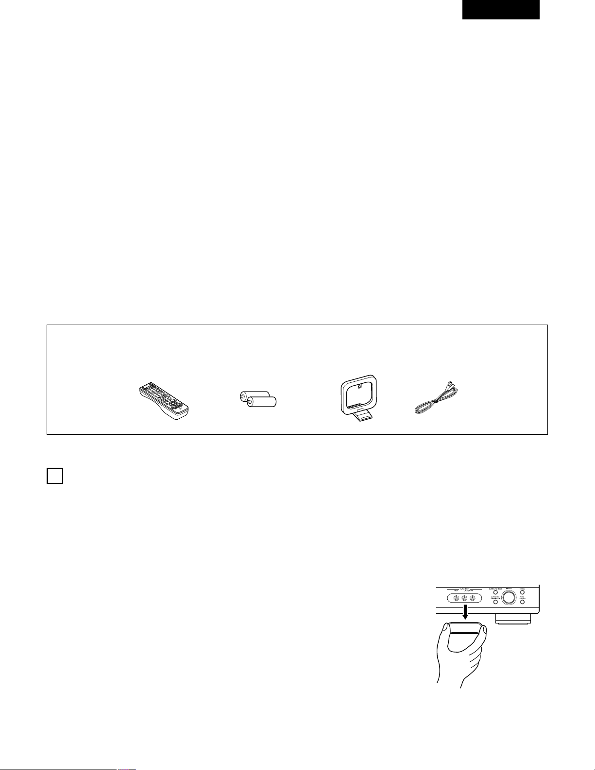
51
FRANCAIS
2 INTRODUCTION
2 ACCESSOIRES
Nous vous remercions d‘avoir choisi l’ampli-tuner A/V Surround de DENON.
Ce remarquable composant a été fabriqué pour fournir une superbe écoute de sons d’ambiance avec des sources de cinéma domestique telles
que DVD, ainsi que pour assurer une formidable reproduction haute fidélité de vos sources musicales favorites.
Ce produit étant équipé d’une immense foule de caractéristiques, nous vous recommandons avant de commencer l’installation et l’utilisation de
l’appareil de bien lire le contenu de ce manuel avant de procéder.
TABLE DES MATIERES
Vérifier que les articles suivants sont inclus dans le carton en plus de l’unité principale:
1
AVANT L‘UTILISATION
Faire attention au points suivants avant d’utiliser cet appareil:
• Déplacement de l’appareil
Pour éviter des court-circuits ou des fils endommagés dans les
câbles de connexion, toujours débrancher le cordon d’alimentation,
et déconnecter les câbles de connexion entre tous les autres
composants audio lors du déplacement de l’appareil.
• Avant de mettre sous tension
Vérifier une nouvelle fois si toutes les connexions sont bonnes et
s’il n’y a pas de problèmes avec les câbles de connexion. Toujours
placer l’interrupteur de mise sous tension en position d’attente
avant de connecter et de déconnecter les câbles de connexion.
• Ranger ces instructions dans un endroit sûr
Après les avoir lues, ranger ces instructions en même temps que
la garantie dans un endroit sûr.
• Noter que les illustrations de ces instructions peuvent varier
de l’appareil actuel dans un but d’explication.
• Borne V. AUX
Le panneau avant du AVR-
1404/484 est équipé d'une
borne V. AUX. Retirer le
capuchon recouvrant la borne
en cas d'utilisation.
q Mode d’emploi........................................................................................1
w Certificat de garantie...............................................................................1
e Liste des centres d’entretien..................................................................1
r Télécommande (RC-942) ........................................................................1
rt y u
t Piles R6P/AA...........................................................................................2
y Antenne-cadre AM..................................................................................1
u Antenne intérieure FM............................................................................1
z
Avant L’utilisation......................................................................................51
x
Précautions D’installation .........................................................................52
c
Précautions de Manipulation....................................................................52
v
Caractéristiques........................................................................................52
b
Nomenclature et Fonctions................................................................53, 54
n
A lire en premier.......................................................................................55
m
Réglage des systèmes d’enceinte ...........................................................55
,
Connexions ........................................................................................56~61
.
Utilisation de la télécommande................................................................62
⁄0
Installation du Systéme......................................................................63~67
⁄1
Unité de Télécommande....................................................................68~72
⁄2
Opération ...........................................................................................73~77
⁄3
Ambiance ...........................................................................................78~83
⁄4
Simulation d’ambiance DSP...............................................................84~88
⁄5
Ecoute de là Radio .....……………………………………………………89~91
⁄6
Mémoire de Dernière Fonction ................................................................92
⁄7
Initialisatione du Microprocesseur..…………………………………………92
⁄8
Informations Supplémentaires...........................................................93~95
⁄9
Dépistage des Pannes..............................................................................96
¤0
Spécifications .…………………………………………………………………97
Liste de codes préréglés ........................................................................98~102
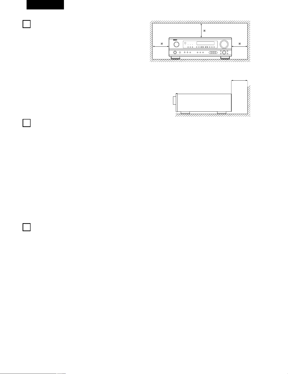
52
FRANCAIS
3
PRECAUTIONS DE MANIPULATION
4
CARACTERISTIQUES
• Commutation de la fonction d’entrée lorsque les prises
d’entrée ne sont pas connectées
Un déclic peut être produit si la fonction d’entrée est commutée
lorsque rien n’est connecté aux prises d’entrée. Dans ce cas,
abaisser la commande MASTER VOLUME (volume de la gamme
entière) ou connecter des composants aux prises d’entrée.
• Mise en sourdine des prises PRE OUT, HEADPHONE et de la
borne SPEAKER
Les prises PRE OUT, HEADPHONE et les bornes SPEAKER sont
équipées d’un circuit de sourdine. Pour cette raison, les signaux de
sortie sont fortement réduits pendant plusieurs secondes après
que l’interrupteur de mise sous tension ait été allumé ou après le
changement de fonction d’entrée, de mode d’ambiance ou de
toute autre installation. Si le volume est augmenté pendant cet
instant, la sortie sera très élevée après l’arrêt du circuit de mise en
sourdine. Toujours attendre que le circuit de mise en sourdine se
désactive avant de régler le volume.
• Chaque fois que l’interrupteur de mise sous tension est en
position STANDBY, l’appareil est toujours connecté à une
tension de ligne secteur.
Toujours débrancher le câble pour aller, par exemple, en
vacances.
1. Décodeur Dolby Pro Logic II
Le système Dolby Pro Logic II est un nouveau format destiné à la
reproduction de signaux audio multivoies disposant de nombreux
avantages sur le système Dolby Pro Logic conventionnel. Il peut
servir à décoder non seulement des sources enregistrées en
Dolby Surround mais il peut aussi transformer des sources stéréo
normales en cinq canaux (avant gauche/droit, centre et surround
gauche/droit). De plus, de nombreux paramètres peuvent être
réglés selon le type de source et son contenu, de façon à
permettre un réglage du son de grande précision.
2. Décodeur numérique Dolby (Dolby Digital)
Le Dolby Digital, un système numérique dans lequel les
différentes chaînes sont complètement indépendantes, recrée
des champs sonores “tri-dimensionnels” (des sons avec une
impression de distance, de mouvement et de position) sans
diaphonie entre les chaînes pour plus de réalisme. De plus, la
gamme de lecture s’étendant jusqu’à 20 KHz des cinq chaînes
(sauf la chaîne 0.1 pour les effets de basse fréquence), la même
que celle des CD, offre un son plus clair et plus richement
expressif.
3. DTS (Digital Theater Systems)
DTS assure jusqu’à 5.1 canaux de son d’ambiance haute fidélité et
large gamme, à partir de sources telles que disque laser, DVD et
disques de musique spécialement encodés.
4. Le DSP haute performance simule 7 champs de son
La lecture est possible dans 7 modes d’ambiance (effet sonore):
5-channel stéréo (5 chaînes stéréo), Mono Movie (Film Mono),
Rock Arena (Concert Rock), Jazz Club, Video Game (Jeux Vidéo)
et Matrix. Vous pouvez apprécier une grande variété d’effets de
son pour différentes scènes de film et sources de programme,
même avec des sources stéréo qui ne soient pas Dolby Surround.
5. Fonction Mémoire Personnelle Plus
La Mémoire Personnelle Plus est une version avancée de
Mémoire Personnelle. Avec la Mémoire Personnelle Plus, le poste
mémorise automatiquement le mode ambiance, le volume de la
chaîne, les paramètres d’ambiance, etc., pour chacune des
sources séparément.
6. Télécommande avec fonction de pré-mémoire
Cet appareil est fourni avec une télécommande équipée d’une
fonction de pré-mémoire. Les codes de commande de la
télécommande pour les composants AV télécommandables
DENON comme les lecteurs disques laser, les platines vidéo, les
télévisions, etc., d’autres grands fabricants sont pré-enregistrés
dans la mémoire.
7. Prises 6CH EXT. IN (prises d’entrée 6 canaux extérieures)
Cet appareil est équipé de prises 6CH EXT. IN pour l’utilisation
avec les formats audio du futur.
2
PRECAUTIONS D’INSTALLATION
L’utilisation simultanée de cet appareil ou d’autres appareils
électroniques à microprocesseur avec un tuner ou un téléviseur peut
produire des parasites dans le son ou l’image.
Si cela se produit, prendre les mesures suivantes:
• Installer cet appareil aussi loin que possible du tuner ou du
téléviseur.
• Eloigner les câbles d’antenne du tuner ou du téléviseur aussi loin
que possible du cordon d’alimentation et des câbles de connexion
d’entrée/sortie de cet appareil.
• Ce problème est fréquemment rencontré lors de l’utilisation
d’antennes intérieures ou de câbles d’arrivée de 300 Ω/ohms.
L’utilisation d’antennes extérieures et de câbles coaxiaux de
75 Ω/ohms est recommandée.
Pour permettre la dissipation de la chaleur, laisser un espace
d’au moins 10 cm (0.3 pieds) entre le haut, l’arrière et les flancs
de cet appareil et le mur ou d’autres composants.
10 cm (0.3 pieds) ou plus
Mur
10 cm (0.3 pieds) ou plus
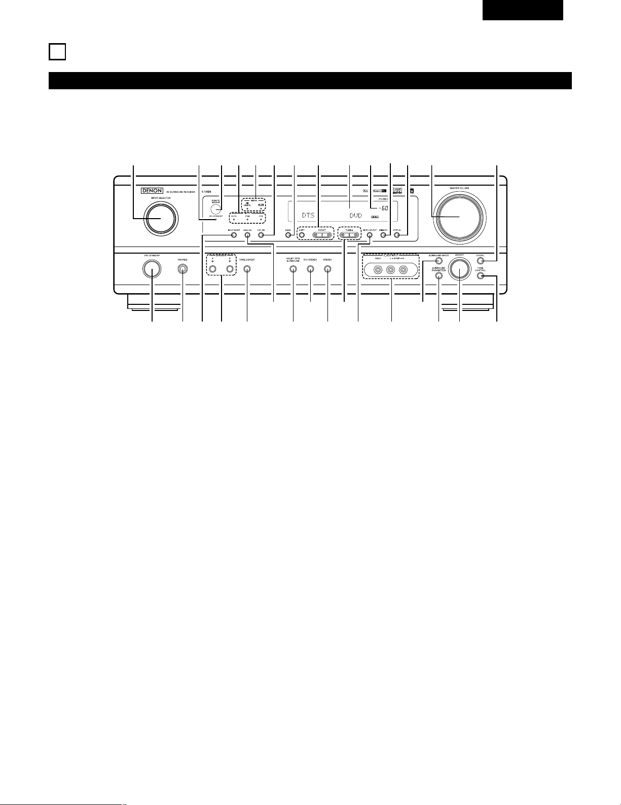
53
FRANCAIS
5
NOMENCLATURE ET FONCTIONS
Panneau avant
• Pour les détails sur les fonctions de ces pièces, se reporter aux pages données entre parenthèses ( ).
q w te ur
y i!3!0
@0@1
@2@3@4@5
@6
@7@8@9
!1 !2 !4 !5 !6o
!7!9 !8#0
q
Interrupteur de mise en marche .................................(64, 73, 89)
w
Prise de casque d’écoute (PHONES) ......................................(76)
e
Touche INPUT MODE........................................................(74, 77)
r
Touche SPEAKER A/B .................................................(73, 76, 92)
t
Touche TONE DEFEAT ...........................................................(75)
y
Touche ANALOG ...............................................................(74, 77)
u
Touche DOLBY/DTS SURROUND .....................................(80, 82)
i
Touche 5CH STEREO ..............................................................(84)
o
Touche STEREO ......................................................................(84)
!0
Touches TUNING D (augmentation) / H (diminution) ..............(90)
!1
Touche VIDEO SELECT ...........................................................(76)
!2
Prises V. AUX INPUT .........................................................(51, 58)
!3
Touche SURROUND MODE..............................................(75, 87)
!4
Touche SURROUND PARAMETER....................................(80, 85)
!5
Sélecteur de SELECT ............................................(75, 79, 80, 87)
!6
Touche TONE CONTROL.........................................................(75)
!7
Touche CH VOL .......................................................................(79)
!8
Commande MASTER VOLUME ..............................................(75)
!9
Touche STATUS .......................................................................(76)
@0
Touche DIMMER .....................................................................(76)
@1
Témoin de volume principal (VOLUME LEVEL)........................(75)
@2
Affichage
@3
Touches de sélection de stations préréglées....................(89, 91)
@4
Touche BAND ..........................................................................(90)
@5
Touche EXT. IN ..................................................................(74, 77)
@6
Indicateurs type de signal (SIGNAL)........................................(75)
@7
Indicateurs mode de entrée (INPUT).......................................(75)
@8
Capteur de télécommande (REMOTE SENSOR) ....................(62)
@9
Indicateur de mise sous tension
#0
Sélecteur de source d’entrée ..................................................(74)
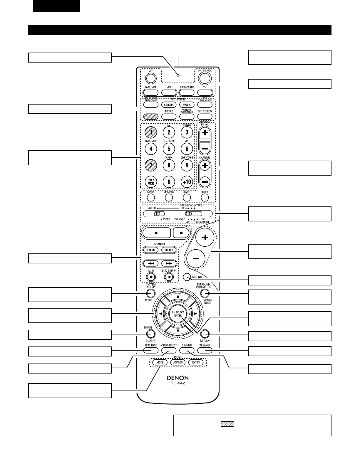
54
FRANCAIS
Unité de télécommande
• Pour les détails sur les fonctions de ces pièces, se reporter aux pages données entre parenthèses ( ).
Touches d’ambiance ..............(75, 80, 85)
Touches de
curseur ......................(63, 70, 78~80, 82)
Touche STATUS/DISPLAY ............(70, 76)
Touche de tonalité d’essai .................(78)
Emetteur de signaux
de télécommande..............................(62)
Touches de commande
MASTER VOLUME ............................(75)
Touches POWER ...................(64, 69~73)
Touche MUTING ................................(76)
Commutateurs de sélection
de mode ..........................(63, 68~70, 72)
Système tuner/
touches Système...................(68, 90, 91)
Touche SYSTEM SET UP/
SETUP..........................................(63, 70)
Sélecteurs de mode
d’entrée........................................(74, 77)
Sélecteurs de source
d’entrée .................................(69~72, 74)
Touches SURROUND PARAMETER
...............................................(70, 80, 85)
Touche CH SELECT/
ENTER..........................................(63, 79)
Touche RETURN ................................(70)
Sélecteur d’enceintes SPEAKER .......(73)
Touche DIMMER................................(76)
Touche VIDEO SELECT......................(76)
Touches de système....................(68, 70)
LED (Indicateur) ...........................(69, 72)
REMARQUE
• Les touches rayées ne fonctionnent pas avec le AVR- 1404/484. (Rien
ne se passe lorsqu’elles sont enfoncées.)
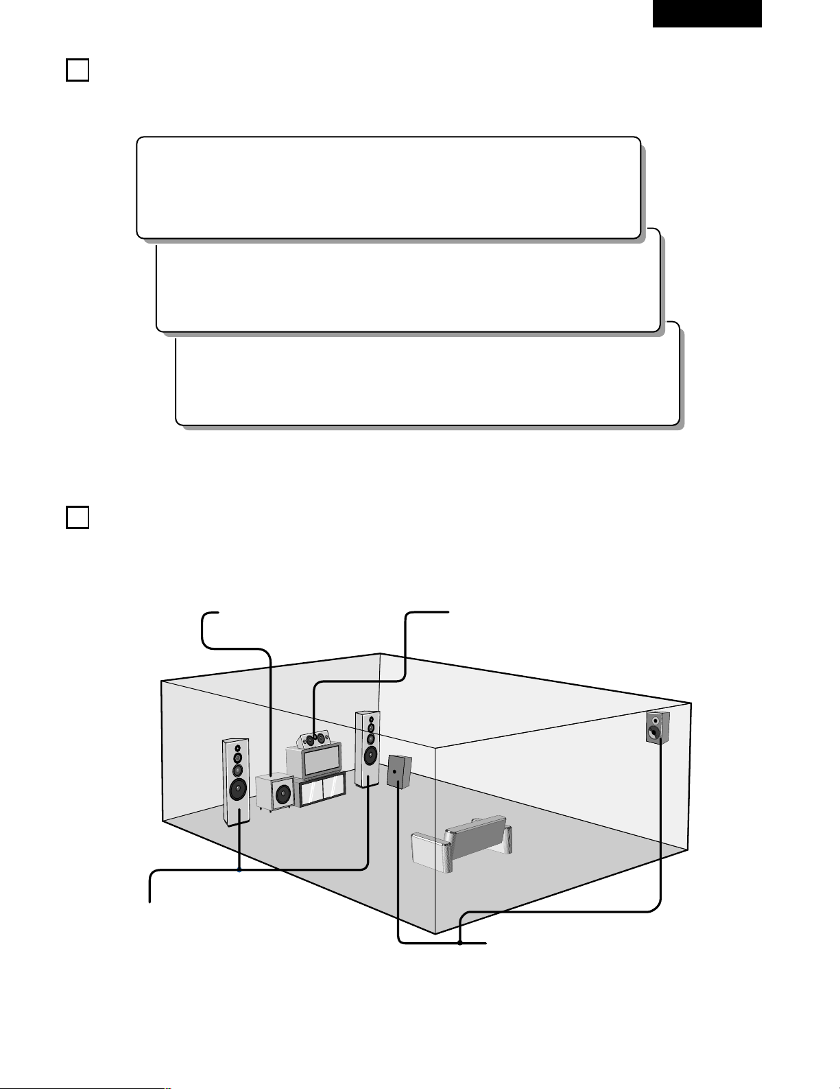
55
FRANCAIS
6
A LIRE EN PREMIER
Ce récepteur d’ambiance AV doit être réglé avant l’utilisation selon les étapes suivantes.
7
RÉGLAGE DES SYSTÈMES D’ENCEINTE
Etape 3 (page 63 à 67)
Finalement, configurer le système.
Etape 2 (page 62)
Ensuite, insérer les piles dans la télécommande.
Etape 1 (page 55 à 61)
Choisir le meilleur emplacement pour l’installation des enceintes et la connexion des composants.
2 Disposition du système d’enceintes
Disposition de base du système
• Ce qui suit est un exemple de la disposition de base pour un système comprenant six systèmes d’enceinte et un moniteur de téléviseur:
Subwoofer Système d’enceintes centrales
Système d’enceintes d’ambiance
Système d’enceintes avant
Placer ces enceintes au niveau des flancs du
téléviseur ou de l’écran avec leurs surfaces avant
autant que possible en regard de l’avant de l’écran.
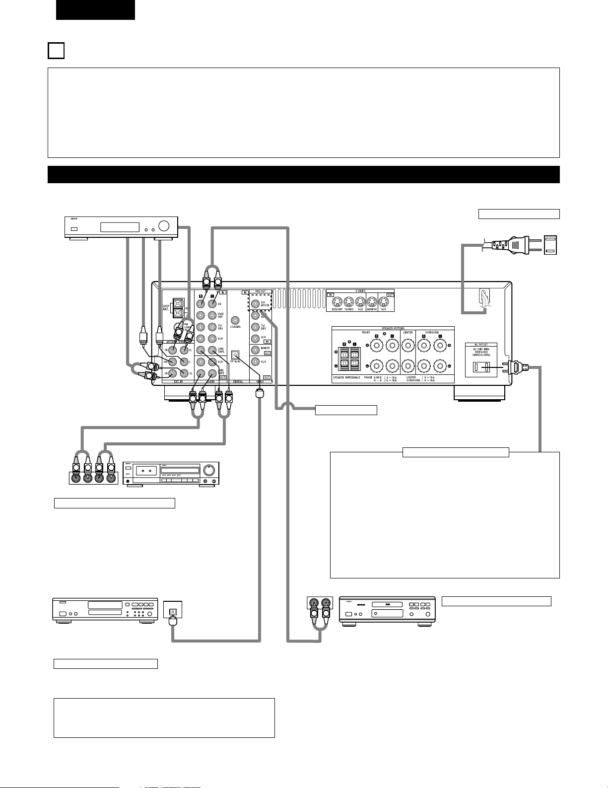
56
FRANCAIS
8
CONNEXIONS
• Ne pas brancher le cordon d’alimentation avant d’avoir terminé
toutes les connexions.
• Toujours connecter correctement les canaux de gauche et de
droite (gauche avec la gauche et droite avec la droite).
• Insérer fermement les fiches. Des connexions incomplètes
peuvent générer des parasites.
•
N’utiliser les prise secteur (AC OUTLET) que pour l’équipement
audio. Ne pas les utiliser pour un sèche-cheveux, etc.
• Remarquer que le groupement de cordons à fiches à broche
avec des cordons d’alimentation, ou le fait de les placer près
d’un transformateur provoque un bourdonnement ou un autre
bruit.
• Un bruit ou un bourdonnement peut être généré si un
composant audio connecté est utilisé indépendamment sans
mettre cet appareil sous tension. Dans ce cas, mettre cet
appareil sous tension.
Connexion des composants audio
LINE OUT
SURROUND
SUB WOOFER
CENTER
FRONT
LINE OUT
LINE OUT
LINE IN
R
OUTPUTINPUT
LRL
R
OUTPUT
L
R
L
R
L
R
L
L
R
L
R
R
L
R
L
L
R
DIGITAL AUDIODIGITAL AUDIO
OUTPUT
OPTICAL
B
Connexion d’un lecteur de CD
Connecter les prises de sortie
analogique (ANALOG OUTPUT) du
lecteur de CD aux prises CD de
cet appareil en utilisant les cordons
à fiches à broche.
Décodeurs avec sorties
analogiques 6 canaux, etc.
Prises numériques (DIGITAL)
Utiliser ces prises pour des connexions à l’équipement audio avec
sortie numérique. Se reporter à la page 67 pour les instructions sur le
réglage de cette borne.
Connexion des prise secteur
PRISE SECTEUR
• Prises commutées (SWITCHED) (capacité totale 120 W (1 A.))
L’alimentation de ces prises est activée et désactivée par
l’interrupteur de mise sous tension (POWER) situé sur l’unité
principale. Ces prises sont également commutées lorsque
l’alimentation est mise en veille (ON-STANDBY) à l’aide de la
télécommande. Lorsque l’AVR-1404/484 est en mode de veille, les
prises sont désactivées. Ne jamais connecter d’équipement dont la
capacité totale est supérieure à 120 W (1 A).
REMARQUE:
N’utiliser les prise secteur (AC OUTLET) que pour l’équipement audio.
Ne jamais les utiliser pour des sèche-cheveux, des télévisions ou
d’autres appareils électriques.
Cordon d’alimentation
120 V CA 60 Hz
Connecter le subwoofer de l’amplificateur interne à la borne
de subwoofer. (Se reporter à la page 60.)
Connexion d’une platine cassette
Connexions pour l’enregistrement:
Connecter les prises d’entrée d’enregistrement (LINE IN ou
REC) de la platine cassette aux prises de sortie (OUT)
d’enregistrement de cassette de cet appareil en utilisant les
cordons à fiches à broche.
Connexions pour la lecture:
Connecter les prises de sortie de lecture (LINE OUT ou PB) de
la platine cassette aux prises d’entrée (IN) de lecture de cassette
de cet appareil en utilisant les cordons à fiches à broche.
Lecteur de CD
Platine cassette ou enregistreur de CD
• Utiliser des cordons à broche de câble de 75 Ω/ohms (vendus
séparément) pour les connexions coaxiales.
• Utiliser des câbles optiques (vendus séparément) pour les
connexions optiques.
Prise Subwoofer
Enregistreurs de CD, MD ou autre
composant équipé de prises de
sortie numérique.
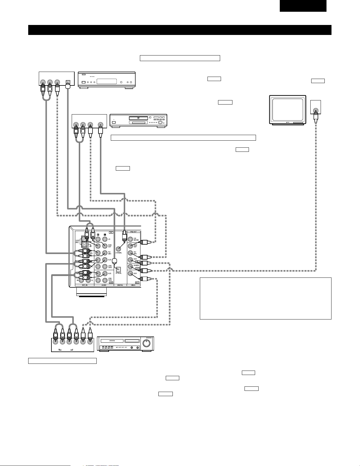
57
FRANCAIS
Connexion des composants vidéo
Pour connecter le signal vidéo, connecter en utilisant un câble de signal vidéo de 75 Ω/ohms. L’utilisation d’un mauvais câble peut entraîner une
baisse de la qualité du son.
IN
VIDEO
R
L
R
L
R
L
L
R
R OUT IN
AUDIO
VIDEO
OUT IN
LRL
R
L
R
L
R OUT
VIDEO
OUT
L
AUDIO
OUT
COAXIAL
DIGITAL
L
R
R OUT
VIDEO
OPTICAL
OUT
L
AUDIO
OUT
DIGITAL
L
R
B
B
Téléviseur ou tuner DBS
Lecteur de DVD ou lecteur de VDP
Moniteur de téléviseur
Connexion d’un téléviseur/tuner DBS
Téléviseur/DBS
• Connecter la prise de sortie vidéo (VIDEO OUTPUT)
du téléviseur ou du tuner DBS à la prise d’entrée de
téléviseur/tuner DBS (TV/DBS IN) (jaune) en
utilisant un cordon à fiches à broche coaxial vidéo de
75 Ω/ohms.
• Connecter la prise de sortie audio (AUDIO OUTPUT)
du téléviseur ou du tuner DBS à la prise d’entrée de
téléviseur/tuner DBS (TV/DBS IN) en
utilisant des cordons à fiches à broche.
AUDIO
VIDEO
Connexion d’un lecteur de DVD ou d’un lecteur de vidéo disque (VDP)
• Connecter la prise de sortie vidéo (VIDEO OUTPUT) du lecteur de DVD (lecteur de
vidéo disque) à la prise d’entrée de DVD/VDP (DVD/VDP IN) (jaune) en
utilisant un cordon à fiches à broche coaxial vidéo de 75 Ω/ohms.
• Connecter la prise de sortie audio analogique (ANALOG AUDIO OUTPUT) du lecteur
de DVD (lecteur de vidéo disque) à la prise d’entrée de DVD/VDP (DVD/VDP IN)
en utilisant des cordons à fiches à broche.
• Pour une meilleure qualité sonore, nous recommandons l’utilisation du lecteur de
DVD avec des connexions numériques plutôt qu’analogiques.
Les lecteurs de DVD et de VDP peuvent également être connectés aux bornes VCR.
AUDIO
VIDEO
Prise de sortie de moniteur (MONITOR
OUT)
• Connecter la prise d’entrée vidéo (VIDEO
INPUT) du téléviseur à la prise de sortie
de moniteur (MONITOR OUT) en
utilisant un cordon à fiches à broche
coaxial vidéo de 75 Ω/ohms.
VIDEO
REMARQUE:
La connexion d’un lecteur de VDP pourvu d’une prise de sortie
Dolby Digital RF.
• Prière d’utiliser un adaptateur disponible dans le commerce pour
la connexion de la prise de sortie Dolby Digital RF du lecteur de
VDP à la prise d’entrée numérique.
Se reporter au manuel d’instructions de l’adaptateur pour la
réalisation des connexions.
Magnétoscope
Connexions d’entrée/sortie vidéo:
• Connecter la prise de sortie vidéo (VIDEO OUT) du magnétoscope à la prise d’entrée de magnétoscope (VCR IN) (jaune) et la prise d’entrée vidéo (VIDEO
IN) du magnétoscope à la prise de sortie de magnétoscope (VCR OUT) (jaune) en utilisant les cordons à fiches à broche coaxial vidéo de 75 Ω/ohms.
Connexion des prises de sortie audio:
• Connecter les prises de sortie audio (AUDIO OUT) du magnétoscope aux prises d’entrée de magnétoscope (VCR IN) et les prises d’entrée audio (AUDIO IN)
du magnétoscope aux prises de sortie de magnétoscope (VCR OUT) en utilisant des cordons à fiches à broche.
AUDIO
AUDIO
VIDEO
VIDEO
Connexion des magnétoscopes
VIDEO OUT
VIDEO IN
VIDEO IN
AUDIO OUT
VIDEO OUT
VIDEO OUT
AUDIO OUT
AUDIO OUT
AUDIO IN
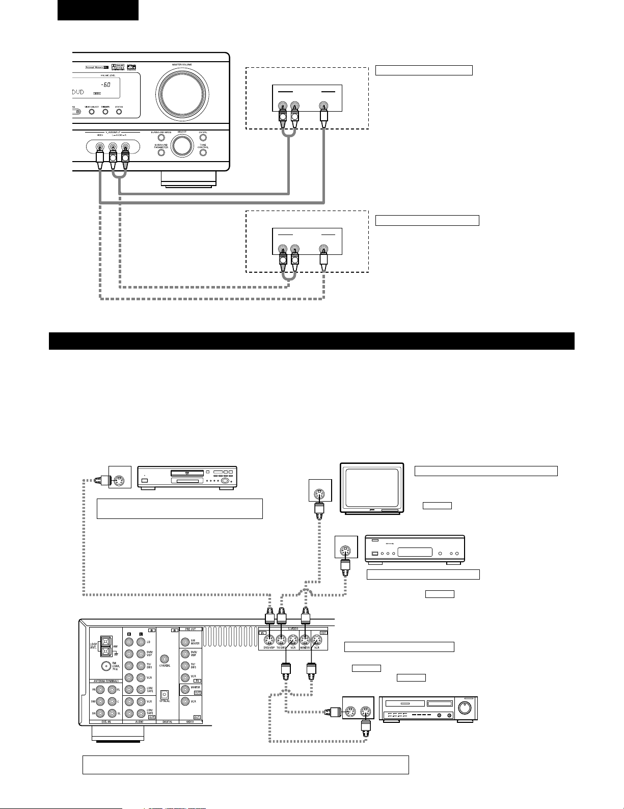
58
FRANCAIS
Connexion d’un composant vidéo équipé de prises vidéo S
• Lors des connexions, se reporter également aux instructions d’utilisation des autres composants.
• Remarque à propos des prises en S
Les sélecteurs d’entrée pour les entrées en S et les entrées des prises à broches fonctionnent conjointement l’un avec l’autre.
• Précautions d’utilisation des prises en S
Les prises en S (entrée et sortie) de cet appareil et les prises à broche vidéo (entrée et sortie) ont des circuits indépendants, de façon à ce que
les signaux vidéo entrés par les prises en S soient envoyés uniquement des sorties des prises en S et les signaux vidéo des prises à broche
sont envoyés uniquement des sorties des prises à broche.
Lors de la connexion de cet appareil à un équipement équipé de prises en S, garder à l’esprit le point ci-dessus et faire les connexions en
respectant le mode d’emploi de chaque équipement correspondant.
IN
S-VIDEO
OUT
S-VIDEO
OUT
S-VIDEO
OUT IN
S-VIDEO
VIDEO IN
VIDEO OUT
VIDEO IN
VIDEO OUT
VIDEO OUT
B
B
Lecteur de DVD, Lecteur de VDP, etc.
Connexion d’un lecteur de DVD ou lecteur de
vidéodisque (VDP)
DVD/VDP
• Connecter la prise de sortie video S (S-VIDEO
OUTPUT) du lecteur de DVD ou lecteur de vidéodisque
à la prise d’entrée de DVD/VDP (DVD/VDP IN) [S-
VIDEO] en utilisant un cordon de connexion vidéo S.
Connexion d’un moniteur de téléviseur
MONITOR OUT
• Connecter la prise d’entrée vidéo en S (S-VIDEO
INPUT) du téléviseur ou du tuner DBS à la prise
MONITOR OUT en utilisant un corden à
prise en S.
S-VIDEO
Moniteur de téléviseur
Connexion d’un TV/tuner DBS
• Connecter la prise de sortie vidéo en S du téléviseur ou tuner
DBS à la prise TV/DBS IN en utilisant un vordon de
connexion à prise en S
S-VIDEO
Téléviseur ou tuner d’émission
par satellite
Platine vidéo
Connexion des lecteurs vidéo
• Connecter la prise de sortie en S du lecteur vidéo à la prise
VCR IN et connecter la prise d’entrée en S du lecteur
vidéo à prise VCR OUT en utilisant de cordons à
prise en S.
S-VIDEO
S-VIDEO
Connecter les entrées et sorties audio des composants la manière décrite à la page 57.
R VIDEO OUTL
OUTPUT
LINE OUT
VIDEO OUT
VIDEO OUT
LINE OUT
R VIDEO OUTL
OUTPUT
L
R
L
R
L
R
Connexion d’un jeu vidéo
• Connecter les jacks de sortie du jeu vidéo au jacks V. AUX
INPUT de cet appareil.
Jeu vidéo
Caméscope
Connexion d’un caméscope
• Connecter les jacks de sortie du caméscope au jacks V. AUX
INPUT de cet appareil.
• La borne V.AUX est recouverte d'un capuchon. Retirer ce
capuchon en cas d'utilisation. (Pour les instructions sur la
manière de retirer le capuchon, voir page 51.)
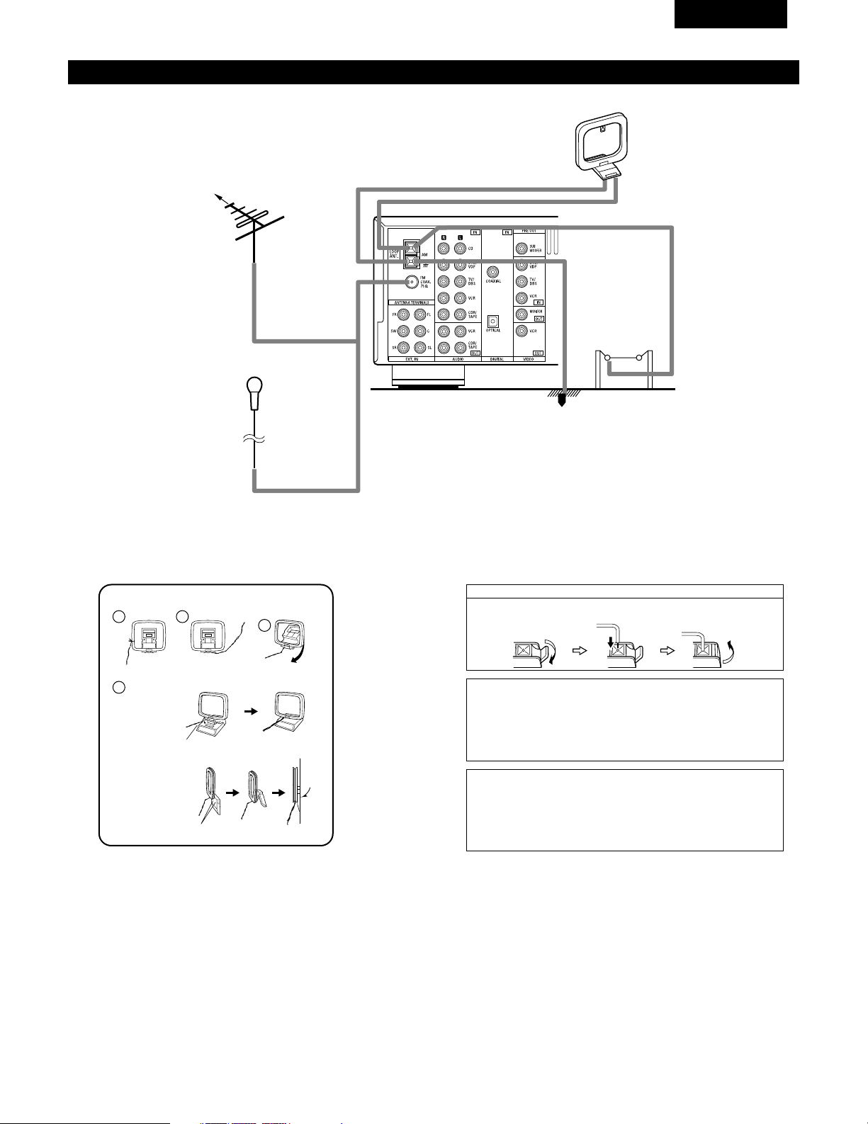
59
FRANCAIS
1
4
2
3
Connexion des bornes d’antennes
DIRECTION DE
STATION DE
RADIODIFFUSION
ANTENNE-CADRE AM
(Accessoire)
ANTENNE FM
TERRE
ANTENNE
EXTERIEURE AM
Antenne intérieure FM
(Accessoire)
CABLE
COAXIAL
DE
75 Ω/ohms
Ensemble d’antenne-cadre AM
Connecter aux
bornes d’antenne AM.
Plier dans la
direction inverse.
Défaire le noeud en
vinyle et sortir la
ligne de connexion.
a. Avec l’antenne sur
le haut de toute
surface stable.
b.Avec l’antenne
fixée au mur.
Monter
Trou d’installation
Monter au mur, etc.
Connexion des antennes AM
1. Appuyer sur
le levier.
2. Insérer le
conducteur.
3. Ramener le
levier.
Remarque à l’installateur de système de télédistribution:
Ce rappel est fourni pour attirer l’attention de l’installateur de système de
télédistribution sur l’article 820-40 du NEC qui fournit des directives sur une
bonne mise à la masse et, en particulier, spécifie que la terre du câble doit
être connectée au système de mise à la masse du bâtiment, aussi près du
point d’entrée de câble que possible.
Remarques:
• Ne pas connecter simultanément deux antennes FM.
• Même si une antenne extérieure AM est utilisée, ne pas
déconnecter l’antenne-cadre AM.
• Vérifier que les bornes de fil d’antenne-cadre AM ne touchent
pas les parties métalliques du panneau.
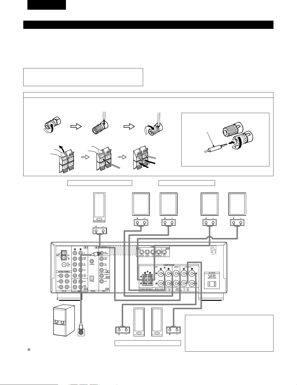
60
FRANCAIS
Connexions du système d’enceintes
• Connecter les bornes d’enceinte aux enceintes en respectant les polarités (<
au <, > au >). Si les polarités ne sont pas respectées, un son central faible
est entendu, l’orientation des divers instruments n’est pas correcte et le sens
de la direction du son stéréo est détérioré.
• Lors de la réalisation des connexions, prendre soin de ne mettre en contact
aucun des conducteurs individuels du cordon d’enceinte avec des bornes
adjacentes, avec des conducteurs d’autres cordons d’enceinte ou avec le
panneau arrière.
Impédance d’enceinte
• Lorsque des systèmes d’enceinte A et B sont utilisés séparément, les
enceintes ayant une impédance de 6 à 16 Ω/ohms peuvent être connectées
pour une utilisation comme enceintes avant.
• Attention, lors de l’utilisation simultanée de deux paires de haut-parleurs ( A
+ B ) à l’avant, bien calculer l’impédance de la combinaison pour qu’elle soit
comprise entre 12 et 16 Ω/ ohms.
• Des enceintes ayant une impédance de 6 à 16 Ω/ohms peuvent être
utilisées comme enceintes centre et ambiance.
• Le circuit de protection peut être activé si le système est reproduit pendant
une longue durée à un volume élevé lorsque des enceintes d’une impédance
inférieure à celle spécifiée sont connectées.
REMARQUE:
• NE JAMAIS toucher les bornes d’enceinte lorsque l’ampli est sous
tension, sinon des décharges électriques risquent de se produire.
Connexion des bornes d’enceinte
1. Tourner dans le sens
contraire des aiguilles
d’une montre pour la
desserrer.
2. Insérer le cordon. 3. Tourner dans le sens
des aiguilles d’une
montre pour la
resserrer.
Connexion des fiches bananes
Tourner dans le sens des aiguilles d’une montre
pour serrer, puis insérer la fiche banane.
(
L
)(
R
)
(
L
) (
R
)(
L
) (
R
)
Prise de connexion pour subwoofer avec
amplificateur incorporé (superwoofer), etc
Pour obtenir un effet de lecture Dolby Digital,
utiliser une unité pouvant reproduire suffisamment
des fréquences inférieures à 80 Hz.
SYSTEME D’ENCEINTES D’AMBIANCE
SYSTEME D’ENCEINTES CENTRALES
SYSTEME D’ENCEINTES AVANT
• Précautions à prendre lors de la connexion des
enceintes
Si une enceinte est placée près d’un téléviseur ou
d’un moniteur vidéo, les couleurs de l’écran peuvent
être perturbées par le magnétisme de l’enceinte. Si
cela se produit, déplacer l’enceinte vers un endroit
où cet effet ne se produit pas.
Fiche banane
1. Pousser la manette. 2. Insérer le cordon. 3. Tirer la manette.
Système B
Système A
61
FRANCAIS
Circuit de protection
• Cet appareil est équipé d’un circuit de protection haute vitesse. Le but de ce circuit est de protéger les enceintes contre
des situations telles que lorsque la sortie de l’amplificateur de puissance est accidentellement court-circuitée et qu’un fort
courant passe, lorsque la température avoisinant l’appareil devient anormalement élevée, ou lorsque l’appareil est utilisé
à puissance élevée pendant une longue durée, ce qui entraîne une augmentation de température extrême.
Lorsque le circuit de protection est activé, la sortie des enceintes est coupée, et la DEL du témoin d’alimentation clignote.
Dans ce cas, suivre ces étapes: toujours couper l’alimentation de cet appareil, vérifier s’il y a des défauts de connexion
des cordons d’enceintes ou des câbles d’entrée, et attendre que l’appareil refroidisse, s’il est très chaud. Améliorer la
ventilation autour de l’appareil, et remettre sous tension.
Si le circuit de protection est à nouveau activé bien qu’il n’y ait pas de problème de câblage ou de ventilation autour de
l’appareil, couper l’alimentation, et contacter un centre d’entretien DENON.
Remarque sur l’impédance des enceintes
• Le circuit de protection peut être activé si l’appareil est utilisé pendant une longue durée à un volume élevé lorsque des
enceintes d’une impédance inférieure à celle spécifiée (par exemple, enceintes ayant une impédance inférieure à 4
Ω/ohms) sont connectées. Si le circuit de protection est activé, la sortie des enceintes est coupée. Couper l’alimentation
de l’appareil, attendre qu’il refroidisse, améliorer la ventilation autour de lui, puis remettre sous tension.
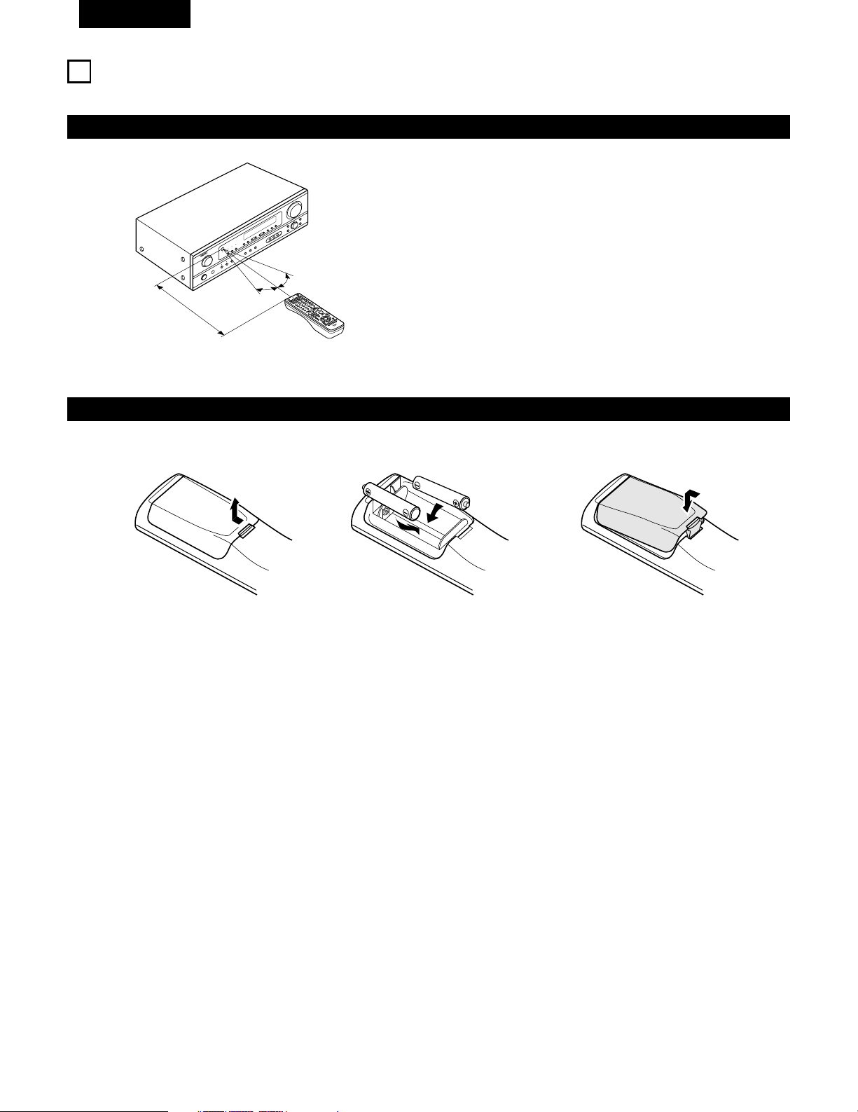
62
FRANCAIS
9
UTILISATION DE LA TÉLÉCOMMANDE
En suivant la procédure expliquée ci-dessous, insérer les piles avant d’utiliser la télécommande.
Plage d’utilisation de la télécommande
Insertion des piles
Diriger la télécommande vers le détecteur de télécommande de la
manière indiquée sur le diagramme de gauche.
REMARQUES:
• La télécommande peut être utilisée à une distance directe
d’environ 7 m (23 pieds), mais cette distance diminue ou le
fonctionnement devient difficile s’il y a des obstacles entre la
télécommande et le détecteur de télécommande, si le détecteur
de télécommande est exposé à la lumière directe du soleil ou à une
autre lumière forte, ou si elle est actionnée d’un angle.
• Des enseignes au néon ou autres dispositifs émettant des
parasites type impulsion à proximité peuvent entraîner un mauvais
fonctionnement, par conséquent garder l’appareil aussi loin que
possible de ces dispositifs.
Approx. 7 m / 23 pieds
30°
30°
w Insérer correctement les piles R6P/AA de
la manière indiquée sur le diagramme.
q Appuyer de la manière indiquée par la
flèche, et retirer en glissant.
e Refermer le couvercle.
REMARQUES:
• N’utiliser que des piles R6P/AA pour le remplacement.
• Vérifier que les polarités sont correctes. (Voir l’illustration à l’intérieur du compartiment à piles.)
• Retirer les piles si l’émetteur de la télécommande n’est pas utilisé pendant une longue période.
• Si des piles fuient, les jeter immédiatement. Eviter de toucher le matériel fuyant ou de le laisser entrer en contact avec un vêtement, etc.
Nettoyer à fond le compartiment à piles avant de mettre de nouvelles piles en place.
• Avoir des piles de remplacement à portée de main de manière à ce que les anciennes piles puissent être remplacées aussi vite que possible
quand il en est temps.
• Même si moins d’un an s’est écoulé, remplacer les piles par des neuves si l’appareil ne fonctionne pas lorsque l’unité de télécommande est
actionnées à proximité. (La pile fournie ne sert que pour la vérification du fonctionnement. La remplacer par une neuve le plus tôt possible.)
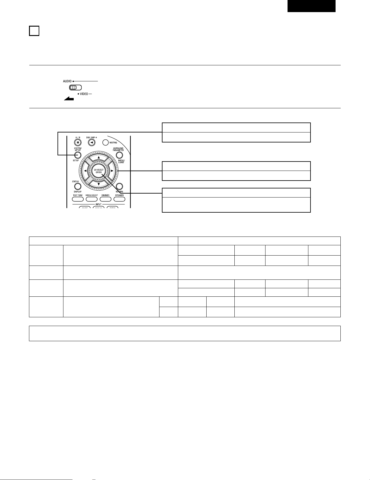
63
FRANCAIS
10
INSTALLATION DU SYSTEME
• Une fois que toutes les connexions avec les autres composants AV ont été faites comme indiqué dans “CONNEXIONS” (voir pages 56 à 61),
faire les différents réglages décrits ci-dessous sur l’affichage.
Ces réglages sont nécessaires pour configurer le système de chambre d’écoute AV centré autour de cette unité.
Touche SYSTEM SETUP
Appuyer pour afficher la configuration du système sur l’affichage.
Touches CURSOR (•, ª, 0, 1)
Appuyez pour modifier ce qui est affiché.
Touche ENTER
Appuyer sur cette touche pour changer l’affichage.
Utiliser également cette touche pour terminer le réglage.
• Articles d’installation de système et valeurs par défaut (réglées à la livraison de l’usine)
Installation de système Valeurs par défaut
Speaker
Configuration
Subwoofer Mode
Digital In
Assignment
Entrer la combinaison des enceintes de votre système et leurs tailles
correspondantes (SMALL pour enceintes normales, LARGE pour pleine
taille, pleine gamme) pour automatiquement régler la composition des
signaux sortis par les enceintes et la réponse en fréquence.
Ceci affecte les prises d’entrées numériques pour les
différentes sources d’entrée.
Source
d’entrée
Entrée
numérique
Front Sp.
Large
Center Sp. Surround Sp. Sub Woofer
Small Small Yes
Front & Subwoofer Center Surround L & R —
12 ft (3.6 m) 12 ft (3.6 m) 10 ft (3.0 m) —
DVD/VDP TV/DBS
COAXIAL OPTICAL
Delay Time
Ce paramètre sert à optimiser la synchronisation avec laquelle sont
produits les signaux audio des enceintes et du subwoofer en fonction
de la position d’écoute.
1
Régler le commutateur coulissant vers “AUDIO”.
2
Utiliser les touches suivantes pour installer le système:
Ceci sélectionne le subwoofer pour la lecture de signaux de
profondes graves.
Subwoofer mode = Normal
REMARQUE:
• La configuration du système n’est pas affichée lorsque “HEADPHONE ONLY” est sélectionnée.
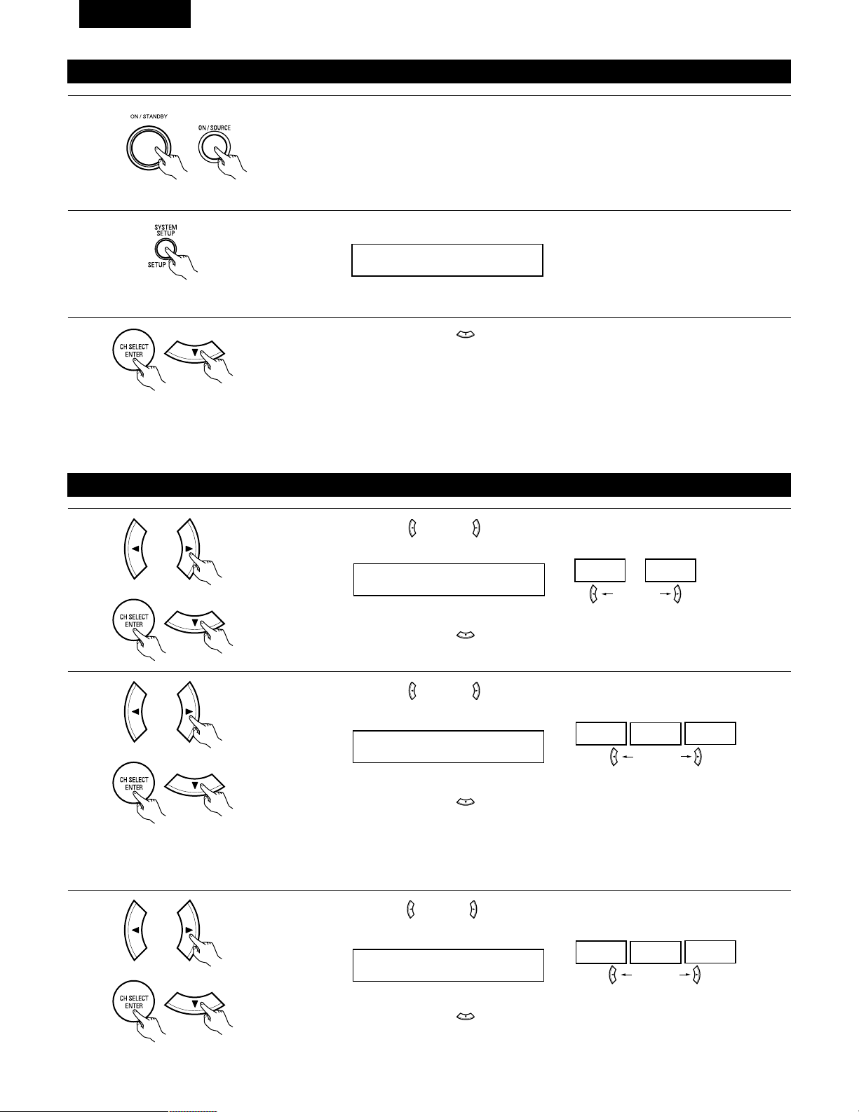
64
FRANCAIS
Avant de configurer le système
1
2
Appuyer sur la touche SYSTEM SETUP pour accéder aux réglages.
Vérifier que tous les composants sont en bon état, puis appuyez sur l’interrupteur de mise en marche
POWER sur l’unité principale ou la touche POWER sur la télécommande pour allumer l’alimentation.
3
Appuyer sur la touche ENTER ou (bas) pour passer à la configuration des haut-parleurs.
*SYSTEM SET UP
REMARQUE:
Appuyer à nouveau sur la touche SYSTEM pour mettre un terme à la configuration. La configuration du système peut être arrêtée à n’importe
quel stade. Tous les changements effectués jusqu’à ce stade seront pris en compte.
REMARQUE: Veuillez vous assurer que le bouton à glissière de la télécommande est en position “AUDIO”.
(Unité principale) (Unité de télécommande)
Configuration des haut-parleurs
1
Utiliser les touches (gauche) et (droit) pour sélectionner le type des haut-parleurs avant installés.
1 FRONT LARGE
LARGE
SMALL
touche (gauche) touche (droit)
Appuyer sur la touche ENTER ou (bas) pour passer au réglage des haut-parleurs centraux.
2
Utiliser les touches (gauche) et (droit) pour sélectionner le type des haut-parleur centraux installés.
2 CENTER SMALL
LARGE
SMALL
NONE
touche (gauche) touche (droit)
Appuyer sur la touche ENTER ou (bas) pour passer au réglage des haut-parleurs “surround”.
3
Utiliser les touches (gauche) et (droit) pour sélectionner le type des haut-parleurs surround installés.
3 SURR. SMALL
LARGE
SMALL
NONE
touche (gauche) touche (droit)
Appuyer sur la touche ENTER ou (bas) pour passer au réglage du subwoofer.
REMARQUE:
• Lorsque l’option “Small” (petit) a été sélectionnée pour les haut-parleurs avant, l’option “Large” (grand) ne peut pas être sélectionnée pour les
haut-parleurs centraux.
(Initial)
(Initial)
(Initial)
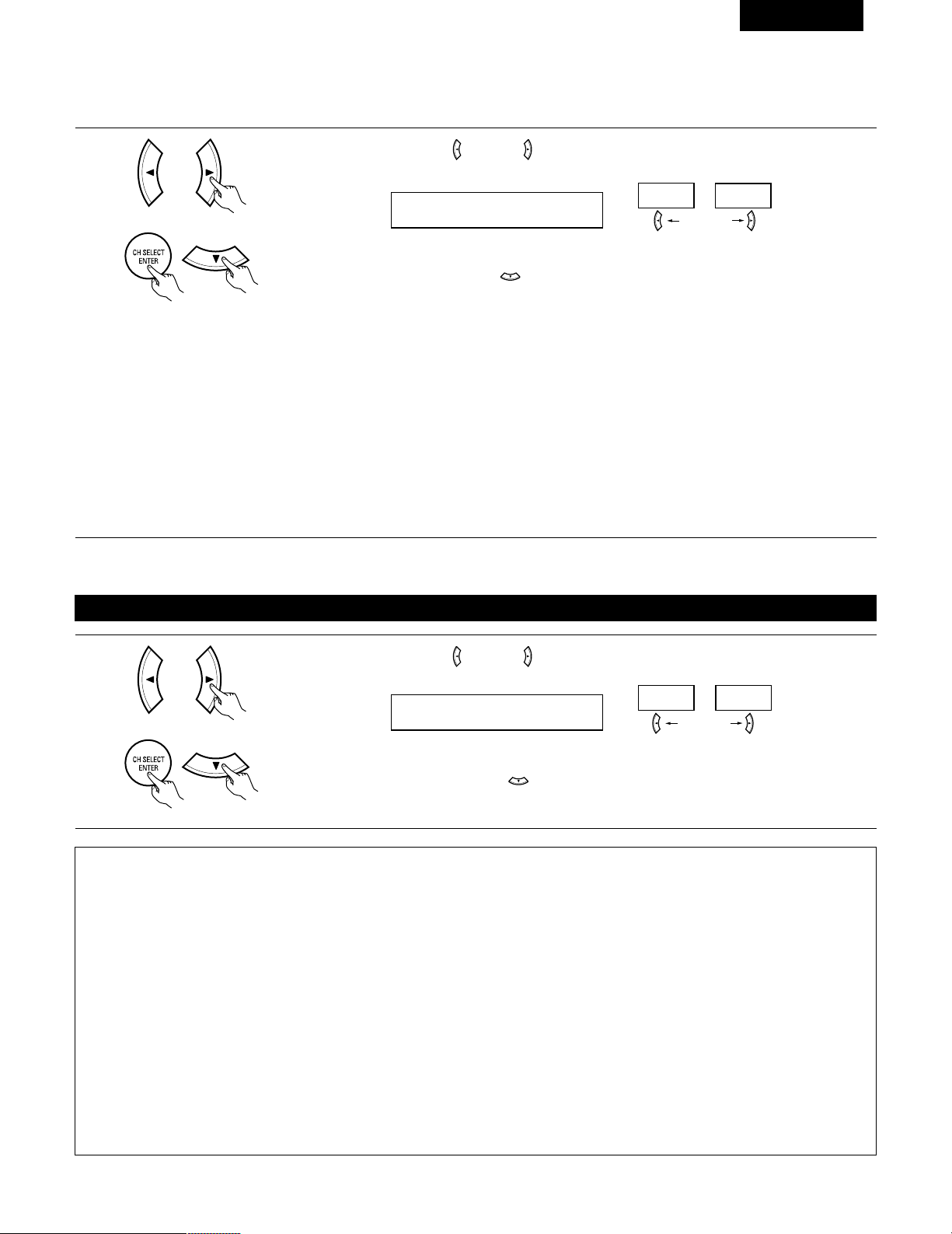
65
FRANCAIS
REMARQUE:
• Lorsque l’option “Small” (petit) a été sélectionnée pour les haut-parleurs avants, l’option “Large” (grand) ne peut pas être sélectionnée pour
les haut-parleurs centraux.
4
Utiliser les touches (gauche) et (droit) pour sélectionner le type de subwoofer installé.
4 S.WOOFER YES
YES
NO
touche (gauche) touche (droit)
Appuyer sur la touche ENTER ou (bas) pour entrer les réglages et passer au réglage de sortie de graves
(SUBWOOFER MODE).
Réglage du mode de subwoofer
1
Utiliser les touches (gauche) et (droit) pour sélectionner le mode de sortie de graves.
5 SW MODE NORM
NORM +MAIN
touche (gauche) touche (droit)
Appuyer sur la touche ENTER ou (bas) pour entrer le réglage et commuter au réglage de la distance
des haut-parleurs.
(Initial)
(Initial)
• Paramètres
Large…… Sélectionner ce paramètre en cas d’utilisation d’enceites pouvant entièrement reproduire des sons faibles inférieurs à 80 Hz.
Small…… Sélectionner ce paramètre en cas d’utilisation d’enceintes ne pouvant pas reproduire des sons faibles inférieurs à 80 Hz avec volume
suffisant. Lorsque ce réglage est sélectionné, les basses fréquences inférieures à 80 Hz sont affectées au subwoofer.
None…… Sélectionner ce paramètre lorsqu’aucune enceinte n’est installée.
Yes/No….Sélectionner “Yes” si un subwoofer est installé, Sélectionner “No” si un subwoofer n’est pas installé.
REMARQUE:
Sélectionner “Large” ou “Small” non pas en fonction de la taille physique de l’enceinte, mais en fonction de la capacité de reproduction de basses
à 80 Hz. Si vous ne pouvez pas déterminer le meilleur réglage, essayer en comparant le son lorsque réglé sur “Small” et lorsque réglé sur
“Large”, à un niveau qui n’endommagera pas les enceintes.
Précaution:
Lorsque le subwoofer n’est pas utilisé, toujours régler “Subwoofer = No”, sinon le son grave du canal avant est divisé en canal de subwoofer et
n’est pas reproduit dans certain mode.
REMARQUES:
— Attribution de la gamme de signaux de basse fréquence —
• Les signaux produits d’un canal de subwoofer sont des signaux LTD (pendant la lecture de signaux Dolby Digital ou DTS) et la gamme de
signal de basse fréquence des canaux réglés sur “SMALL” dans la configuration de la gamme de signaux de basse fréquence des canaux
réglés sur “LARGE” sont produits à partir de ces canaux.
— Mode subwoofer —
• Le mode subwoofer n’est effectif que si les enceintes avant sont réglées sur “LARGE” et le subwoofer sur “YES” (Oui) dans le menu
“Configuration des haut-parleurs” (Voir page 64, 65).
Si les enceintes avant sont réglées sur “SMALL” ou le subwoofer sur “NO” (Non), le réglage du mode subwoofer n’a aucun effet sur la
lecture de la gamme des signaux de basse fréquence.
• Lorsque le mode de lecture “+MAIN” (+Principaux) est sélectionné, la gamme des signaux de basse fréquence des canaux réglés sur
“LARGE” est produite simultanément pour ces canaux et le canal subwoofer.
Dans ce mode de lecture, la gamme des signaux de basse fréquence remplit la pièce de manière plus régulière mais, suivant les dimensions
et la forme de cette pièce, des interférences peuvent se produirent à cause de la diminution du volume de la gamme des signaux de basse
fréquence.
• Lorsque le mode de lecture “NORM” est sélectionné, la gamme des signaux de basse fréquence des canaux réglés sur “LARGE” est
uniquement produite à partir de ces canaux. Dans ce mode de lecture il y a peu d’interférences de gamme basse fréquence dans la pièce.
• Essayez une source musicale ou un film et sélectionnez le mode de lecture qui procure le son de basse fréquence le plus fort.
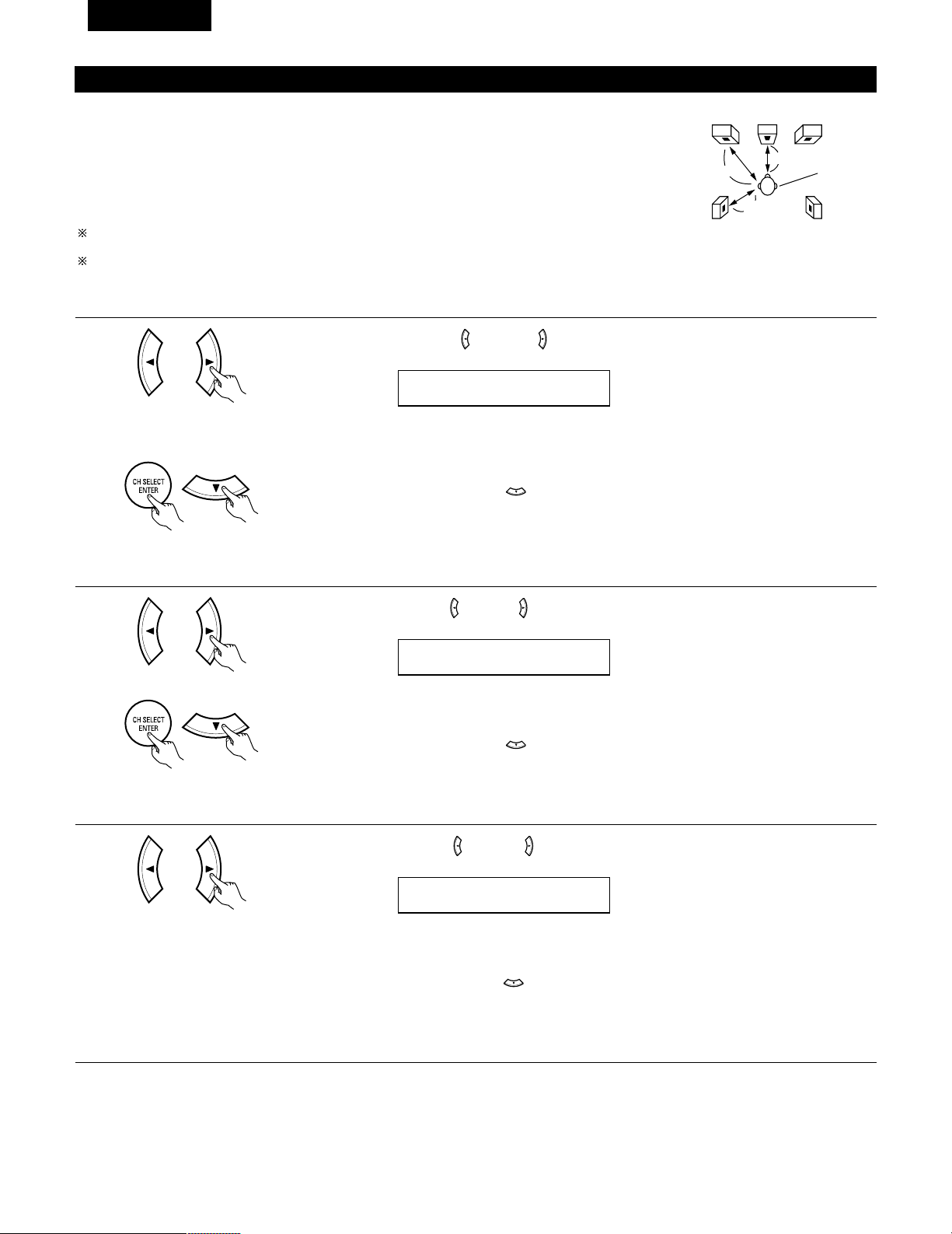
66
FRANCAIS
Reglage de la distance des haut-parleurs
Entrer les distances de la postion d’écoute aux enceintes, et régler le temps de retard d’ambiance.
Préparations:
Mesurer les distances de la position d’écoute aux enceinte (L1 à L3 sur le diagramme de droite.)
L1: Distance de l’enceinte centrale à la position d’écoute
L2: Distance des enceintes frontales à la position d’écoute
L
3: Distance entre chaque haut-parleur surround et le centre d’écoute
ATTENTION:
Placer l’enceinte centrale à la égale distance des enceintes principales (gauche et droite) ou du
subwoofer, ou de telle façon que la différence de distance (L2 – L1) soit égale ou inférieure à 5 pieds.
Placer les enceintes d’ambiance (gauche et droite) à égale distance des enceintes principales (gauche
et droite) ou du subwoofer, ou de telle façon que la différence de distance (L2 – L3) soit égale ou
inférieure à 15 pieds.
L1
L2
L3
FL
Central FR
Position
d’écoute
SL
SR
1
Utiliser les touches (gauche) et (droit) pour régler la distance entre les haut-parleurs avant, le
subwoofer et le centre d’écoute.
6 FRNT/SW 12ft
• Le chiffre de distance change d’un pied (ft) à chaque pression sur une des touches. Choisir la valeur la
plus proche de la distance mesurée.
(“SW” n’apparaît que lorsque subwoofer = yes).
Appuyer sur la touche ENTER ou (bas) pour passer au réglage du haut-parleur central.
REMARQUE:
• La distance des haut-parleurs peut être ajustée entre 0 et 60 pieds en étapes de 1 pied.
2
Utiliser les touches (gauche) et (droit) pour régler la distance entre le haut-parleur central et le centre
d’écoute.
7 CENTER 12ft
• Le chiffre de distance change d’un pied (ft) à chaque pression sur une des touches. Choisir la valeur la
plus proche de la distance mesurée.
Appuyer sur la touche ENTER ou (bas) pour passer au réglage du haut-parleur surround.
REMARQUE:
• Il n’y a pas de réglage lorsque “None” (aucun) a été sélectionné pour le haut-parleur central.
3
Utiliser les touches (gauche) et (droit) pour régler la distance entre les haut-parleurs surround et le
centre d’écoute.
8 SURR. 10ft
• Le chiffre de distance change d’un pied (ft) à chaque pression sur une des touches. Choisir la valeur la
plus proche de la distance mesurée.
Appuyer sur la touche ENTER ou (bas) pour entrer le réglage et passer au réglage d’entrée numérique
(COAX).
REMARQUE:
• Il n’y a pas de réglage lorsque “None” (aucun) a été sélectionné pour le haut-parleur surround.
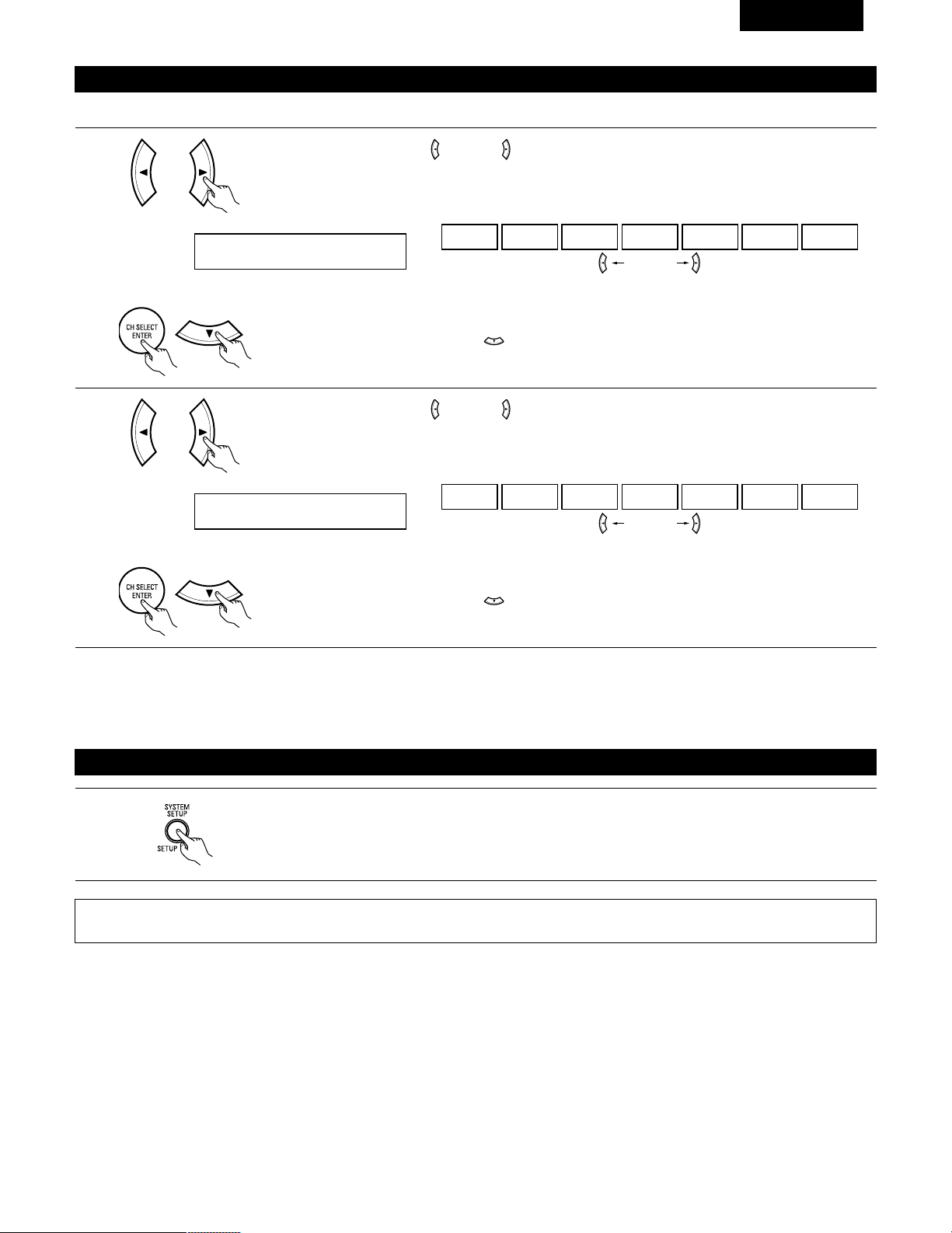
67
FRANCAIS
Réglage de l’assignation d’entrée numérique “Digital In Assignment”
Sélectionner le type d’appareil connecté aux bornes de l’entrée numérique.
1
Utiliser les touches (gauche) et (droit) pour attribuer la fonction d’entrée connectée à la borne d’entrée
COAXIAL (COAXIAL).
9 COAX DVD
CD DVD TV VCR V.AUX CDR OFF
• Sélectionner “OFF” (arrêt) si aucun appareil n’est connecté.
Appuyer sur la touche ENTER ou (bas) pour passer au réglage d’entrée optique (OPT).
touche (gauche) touche (droit)
2
Utiliser les touches (gauche) et (droit) pour attribuer la fonction d’entrée connectée à la borne d’entrée
OPTICAL (OPTICAL).
10 OPT TV
CD DVD TV VCR V.AUX CDR OFF
• Sélectionner “OFF” (arrêt) si aucun appareil n’est connecté.
Appuyer sur la touche ENTER ou (bas) si l’on veut démarrer les réglages depuis le début.
touche (gauche) touche (droit)
(Initial)
(Initial)
REMARQUE:
• TUNER ne peuvent pas être sélectionnés.
Apres avoir configure le système
1
Appuyer sur la touche SYSTEM SETUP pour terminer la configuration du système.
Ceci termine les opérations de configuration du système. Une fois la configuration terminée, il n’est plus nécessaire d’effectuer de changement
sauf si un nouvel élément est ajouté ou si la disposition des haut-parleurs est modifiée.
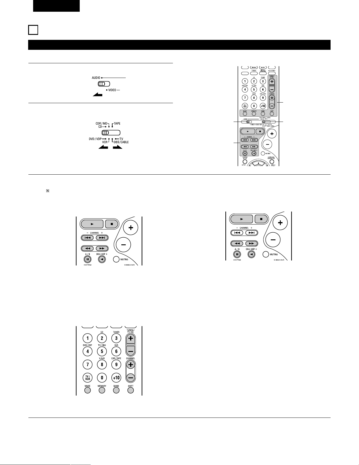
68
FRANCAIS
Utilisation des composants audio DENON
• Mettre les différents composants sous tension avant de les utiliser.
1
2
3
Régler le commutateur de mode 1 sur “AUDIO”.
Régler le commutateur de mode 2 à la position du composant
à utiliser. (CD, CDR/MD ou platine cassette)
Actionner le composant audio.
• Pour les détails, se reporter aux instructions d’utilisation du composant.
Alors que cette télécommande est compatible avec une large gamme de composants contrôlés par infrarouges, certains modèles de
composants peuvent ne pas être actionnés avec cette télécommande.
1. Touches de lecteur et d’enregistreur de disques (CD) et
de système d’enregistrement de MD (CDR/MD)
3. Touches de système de tuner
2. Touches de système de platine cassette (TAPE)
3
2
1
3
6, 7 : Recherche manuelle (en arrière et en avant)
2 : Arrêt
1 : Lecture
8, 9 : Recherche automatique (repérage)
3 : Pause
DISC : Changer les disques
SKIP+ (uniquement pour changeurs de CD)
SHIFT : Changer la plage de canaux préréglés
CHANNEL : Augmentation/diminution de canal préréglé
+, –
TUNING : Augmentation/diminution
+, – de fréquence
BAND : Changer entre les bandes AM et FM
MODE : Changer entre auto et mono
MEMORY : Mémoire préréglée
6 : Rembobinage
7 : Avance rapide
2 : Arrêt
1 : Lecture en avant
0 : Lecture en arrière
A/B : Changer entre les platines A et B
11
UNITE DE TELECOMMANDE
REMARQUE:
• Le TUNER peut être utilisé lorsque le commutateur est placé en position “AUDIO”.
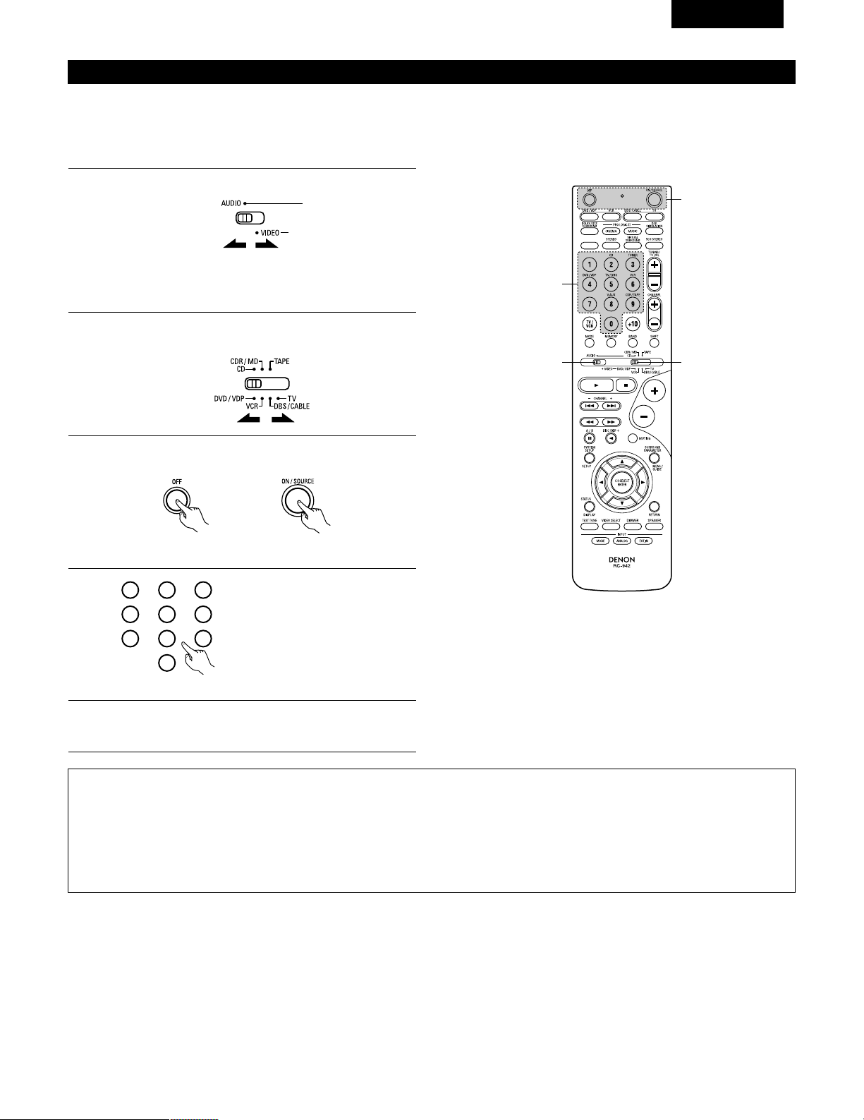
69
FRANCAIS
Mémoire préréglée
DENON et d’autres fabricants de composants peuvent être actionnés en réglant la mémoire préréglée.
La télécommande peut être utilisée pour faire fonctionner les composants d’autres marques sans utiliser la fonction d’apprentissage en
enregistrant la marque du composant comme indiqué sur la liste de codes préréglés (page 98~102).
L’opération n’est pas possible pour certains modèles.
1
2
Régler le commutateur de mode 1 sur “AUDIO” ou “VIDEO”.
Régler le commutateur de mode 2 sur le composant à
enregistrer.
3
2
1
4
Régler sur AUDIO pour la position CD, platine cassette et
CDR/MD, régler sur VIDEO pour la position DVD/VDP,
DBS/CABLE, VCR ou TV.
3
Appuyer simultanément sur les touches ON/SOURCE et OFF.
• L’indicateur clignote.
4
5
En référence à la Liste des Codes
Préréglés inclue, utilisez les
boutons à numéro pour entrer le
code de préréglage (un numéro à 3
chiffres) pour le fabriquant du
composant dont vous vous voulez
emmagasiner les signaux en
mémoire.
Pour sauvegarder les codes d’un autre composant dans la
mémoire, répéter les étapes 1 à 4.
Les codes préréglés sont comme suit à la livraison de l’usine et après réinitialisation:
TV, VCR ..............................................HITACHI
CD, TAPE............................................DENON
CDR/MD .............................................DENON (CDR)
DVD/VDP ............................................DENON (DVD)
DBS/CABLE........................................ABC (CABLE)
1
2
3
456
789
0
REMARQUES:
• Les signaux des touches préréglées sont émis pendant le réglage de la mémoire préréglée. Pour éviter une utilisation accidentelle de la
télécommande, couvrir la fenêtre de l’émetteur pendant le réglage de la mémoire préréglée.
• En fonction du modèle et de l'année de fabriquation, cette fonction ne peut pas être utilisée pour certains modèles, même s'ils sont listés
en fabrique sur la liste inclue des codes de préréglage.
• Certains fabriquants utilisent plus d'un type de code de télécommande. Référez-vous à la liste incluse des codes de préréglage pour changer
le numéro et vérifier.
• La mémoire préréglée peut être réglée pour un composant seulement parmi CDR/MD, DVD/VDP et DBS/CABLE.
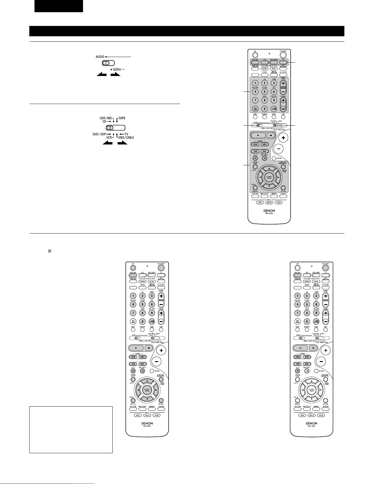
70
FRANCAIS
Rappel des station avec les touches prétéglées
1
2
Régler le commutateur de mode 1 sur “AUDIO” ou “VIDEO”.
Régler le commutateur de mode 2 sur le composant à utiliser.
3
2
1
3
3
Régler sur AUDIO pour la position CD, platine cassette et
CDR/MD, régler sur VIDEO pour la position DVD/VDP,
DBS/CABLE, VCR ou TV.
1. Touches de système de lecteur
de vidéodisque numérique
(DVD, DVD SETUP)
POWER : Mise sous/attente tension
(ON/SOURCE)
OFF : MIse hors tension de
DENEN DVD
6,7 : Recherche manuelle
(en avant et en arrière)
2 : Arrêt
1 : Lecture
8,9 : Recherche automatique
(au début de plage)
3 : Pause
0 ~ 9, +10 : Touche 10
skip + : Saut de disque
(pour changeur de DVD)
DISPLAY : Changer l’affichage
MENU : Menu
RETURN : Retour de menu
SETUP : Retour de menu
•, ª,
0
,
1
: Curseur vers le haut, bas,
gauche et droite
ENTER : Enter réglage
2. Touches de système de lecteur
de vidéodisque (VDP)
POWER : Mise sous/attente tension
(ON/SOURCE)
6,7 : Recherche manuelle
(en avant et en arrière)
2 : Arrêt
1 : Lecture
8,9 : Recherche automatique
(repérage)
3 : Pause
0~9, +10 : Touche 10
3
Actionner le composant.
• Pour les détails, se reporter aux instructions d’utilisation du composant.
Certains modèles ne peuvent pas être actionnés avec cette unité de télécommande.
REMARQUE:
• Certains fabricants utilisent des
noms différents pour les touches
de commande de DVD, donc se
reporter également aux
instructions de télécommande de
ce composant.
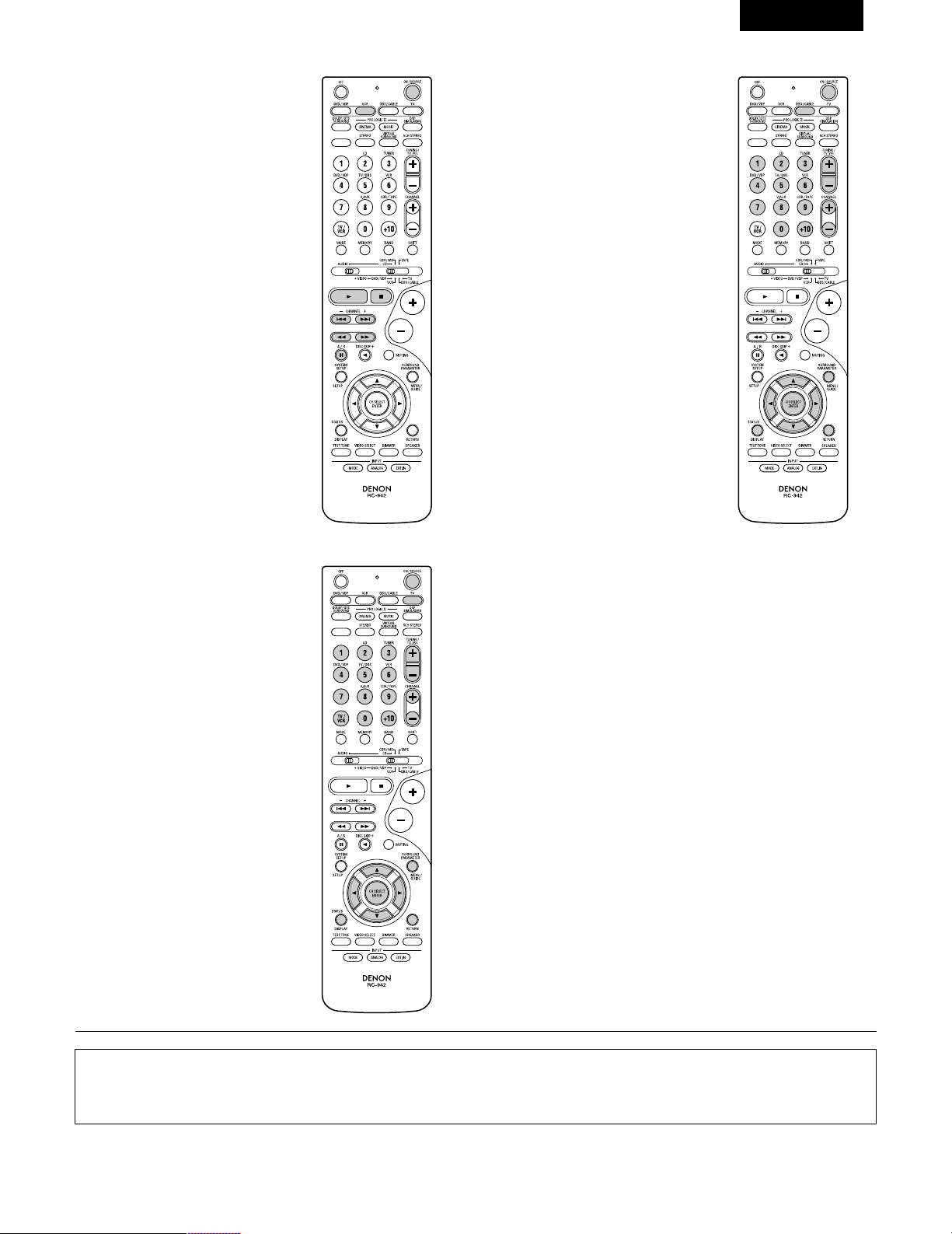
71
FRANCAIS
3. Touches de système de platine
vidéo (VCR)
4. Touches de système de tuner
d’émission par satellite (DBS) et
de télédistribution (CABLE)
POWER : Mise sous/attente tensiony
(ON/SOURCE)
6,7 : Recherche manuelle
(en avant et en arrière)
2 : Arrêt
1 : Lecture
3 : Pause
Channel +, – : Canaux
POWER : Mise sous/attente tension
(ON/SOURCE)
MENU : Menu
RETURN : Retour de menu
•, ª,
0
,
1
: Curseur vers le haut, bas,
gauche et droite
ENTER : Entrer
CHANNEL : Changer de canaux
+, –
0~9, +10 : Canaux
DISPLAY : Changer l’affichage
VOLUME : Augmentation/baisse de
+, – volume
5. Touches de système de TV avec
moniteur (TV)
POWER : Mise sous/attente tension
(ON/SOURCE)
MENU : Menu
RETURN : Retour de menu
•, ª,
0
,
1
: Curseur vers le haut, bas,
gauche et droite
ENTER : Enter
CHANNEL : Changer de canaux
+, –
0~9, +10 : Canaux
DISPLAY : Changer l’affichage
TV/VCR : Changer entre TV et
magnétoscope
VOLUME : Augmentation/baisse de
+, – volume
REMARQUES:
• Pour ce composant CD, CDR, MD et TAPE, les touches peuvent être utilisées de la même manière que pour les composants audio DENON
(page 68).
• Le téléviseur peut être utilisé lorsque le commutateur est en position DVD/VDP, VCR, TV.
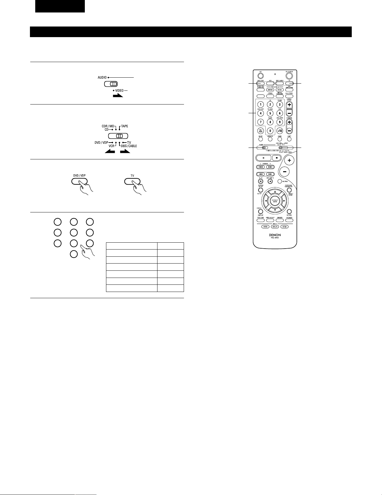
72
FRANCAIS
Tension de pénétration (Punch Through)
•“Punch Through” (tension de pénétration) est une fonction permettant d’utiliser les touches PLAY, STOP, MANUAL SEARCH et AUTO SEARCH
des composants CD, TAPE, CDR/MD ou VCR en mode DBS/CABLE ou TV. Le réglage par défaut est sur aucun composant.
1
2
Régler le commutateur de mode 1 sur “VIDEO”.
Régler le commutateur de mode 2 sur le composant à
enregistrer (DBS/CABLE ou TV).
3
2
1
4
3
3
Appuyer sim ultanément sur les touches DVD/VDP et TV.
• L’indicateur clignote.
4
Entrer le numéro du composant à
régler. (Voir le tableau 1).
1
2
3
456
789
0
Tableau 1
CD
TAPE
CDR/MD
DVD/VDP
VCR
Aucun réglage
No.
1
2
3
4
5
0
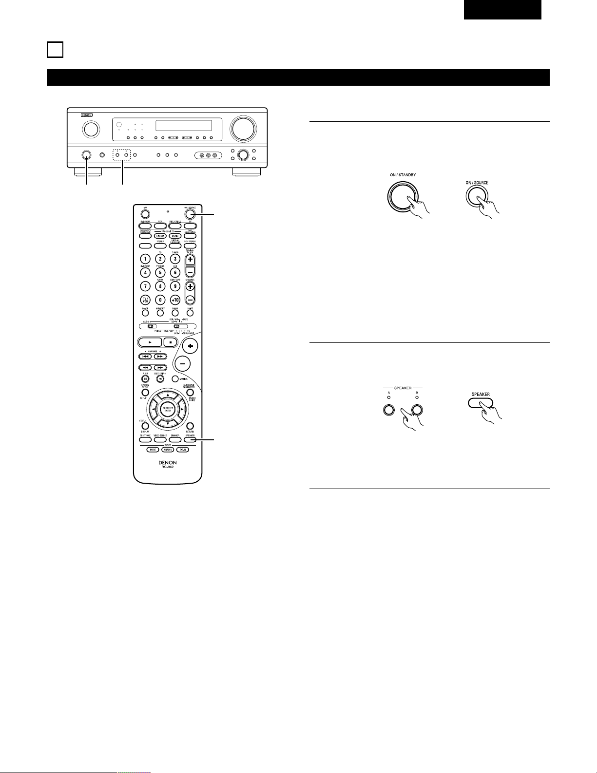
73
FRANCAIS
12
OPERATION
Avant l’utilisation
Préparatifs:
Vérifier que toutes les connexions sont bonnes.
1
Allumer l’alimentation.
Appuyer sur la touche ON/STANDBY sur l’unité principale ou
sur la touche ON/SOURCE sur la télécommande pour la
mettre sous tension.
2
Sélectionner les enceintes avant.
Appuyer sur le commutateur d‘enceinte A ou B pour activer
l’enceinte.
(Unité principale) (Unité de télécommande)
1 2
1
2
• ON/STANDBY (sous tension/attente)
Lorsqu’on appuie sur la touche, l’alimentation s’allume et
l’affichage s’éclaire pendant environ une seconde.
Lorsqu’on appuie encore, l’alimentation s’éteint, le mode
de veille est mis et l’affichage s’éteint.
Quelques secondes s’écoulent entre le moment où
l’interrupteur de mise sous tension a été mis en position
“ON” et le début d’émission de son. Ceci est dû au circuit
de mise en sourdine qui évite le bruit lors de la mise sous
et hors tension.
(Unité principale) (Unité de télécommande)
• Le réglage A, B de l’enceinte frontale peut également être
modifié à l’aide de la touche SPEAKER de la
télécommande.
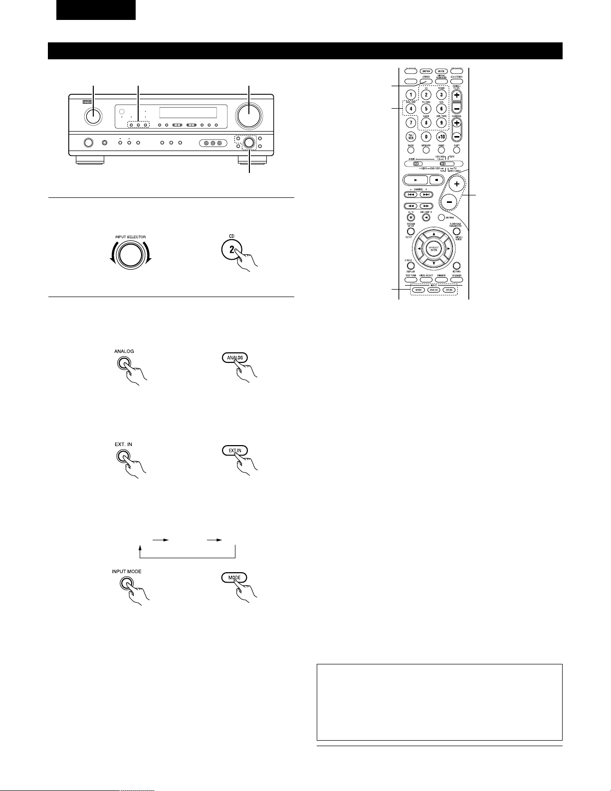
74
FRANCAIS
Lecture de la source de programme analogique
3
1 2 5
Fonction de sélection de mode d’entrée
Différents modes d’entrée peuvent être sélectionnés pour les
différentes sources d’entrée. Les modes d’entrée sélectionnés pour
les sources d’entrée séparées sont sauvegardés dans la mémoire.
q AUTO (mode auto)
Dans ce mode, les types de signaux entrés dans les prises
d’entrée numérique et analogique pour la source d’entrée
sélectionnée sont détectés et le programme dans le décodeur
d’ambiance de cet appareil est sélectionné automatiquement à la
lecture. Ce mode peut être sélectionné pour toutes les sources
d’entrée autres que TUNER.
La présence ou l’absence de signaux numériques est détectée,
les signaux entrés vers les prises d’entrée numérique sont
identifiés et le décodage et la lecture sont automatiquement
effectués en format DTS, Dolby Digital ou PCM (stéréo 2 canaux).
Si aucun signal numérique n’est entré, les prises d’entrée
analogique sont sélectionnées.
Utiliser ce mode pour lire des signaux au format Dolby Digital.
w PCM (mode de lecture exclusive de signaux PCM)
Le décodage et la lecture ne sont effectués que lorsque des
signaux PCM sont entrés.
Romarquer que des parasites peuvent être générés en cas
d’utilisation de ce mode pour lire des signaux qui ne sont pas au
format PCM.
e DTS (mode de lecture exclusive de signaux DTS)
Le décodage et la lecture ne sont effectués que lorsque des
signaux DTS sont entrés.
r
ANALOG (mode de lecture exclusive de signaux audio analogiques)
Les signaux entrés vers les prises d’entrée analogique sont
décodés et joués.
t
EXT. IN (mode de sélection de prise d’entrée de décodeur externe)
Les signaux entrés vers les prises d’entrée de décodeur externe
sont reproduits sans passer par le circuit d’ambiance.
REMARQUE:
• Remarquez que du bruit va être émis lorsque des CD ou des LD
enregistrés en format DTS sont lus dans le mode “PCM”(lecture
calibré pour le signal PCM) ou “ANALOG” (lecture calibrée pour un
signal audio analogique). Choisissez le mode AUTO ou DTS
(lecture calibrée pour le signal DTS) quand vous lisez des
enregistrements de format DTS.
5
1
3
2
1
Sélectionner la source d’entrée à jouer.
Exemple: CD
(Unité principale) (Unité de télécommande)
2
Sélectionner le mode d’entrée.
• Sélection du mode analogique
Appuyer sur la touche ANALOG pour passer à l’entrée
analogique.
(Unité de télécommande)
• Sélection du mode d’entrée externe (EXT. IN)
Appuyer sur EXT. IN (sur la touche EXT. IN de l’unité de
télécommande) pour changer l’entrée externe.
(Unité principale) (Unité de télécommande)
• Sélection des modes AUTO, PCM et DTS
Le mode change de la manière indiquée ci-dessous chaque
fois que la touche INPUT MODE button est enfoncée.
AUTO PCM DTS
(Unité principale)
(Unité principale) (Unité de télécommande)
Remarques sur la reproduction d’une source encodée avec DTS
• Du bruit parasite peut apparaître arec amorce au début de
la lecture et pendant la recherche en cours de lecture d’un
DTS dans le mode automatique. Si cela se produit, écouter
les DTS dans un mode précis.
• Dans certains cas rares des bruits parasites peuvent se
produire lorsque vous arrêtez la lecture d'un DTS-CD ou
d'un DTS-LD.
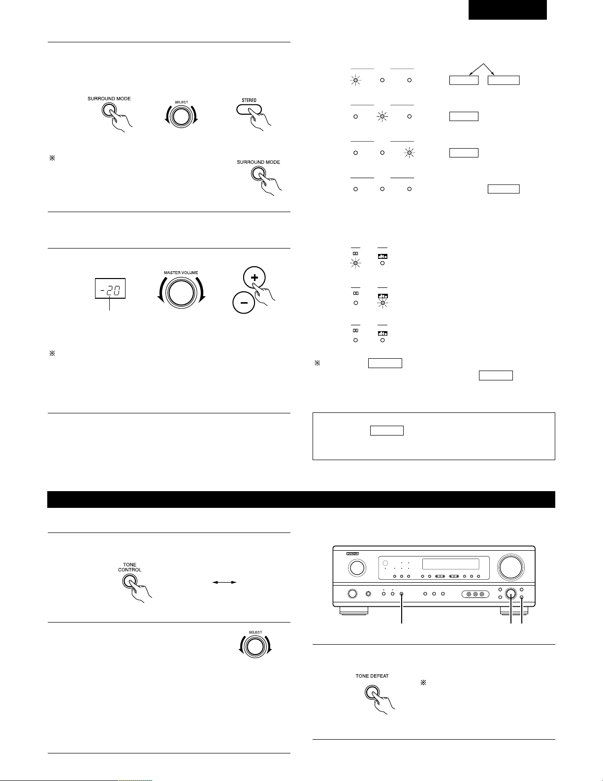
75
FRANCAIS
• Pour augmenter les graves ou les aiguës: Tourner la
commande dans le sens des aiguilles d’une montre. (Le
son de graves ou d’aiguës peut être augmenté jusqu’à +10
dB en étapes de 2 dB.)
• Pour diminuer les graves ou les aiguës: Tourner la
commande dans le sens des aiguilles d’une montre. (Le
son de graves ou d’aiguës peut être réduit jusqu’à –10 dB
en étapes de 2 dB.)
Pour sélectionner le mode d’ambiance pendant
le réglage des paramètres d’ambiance, le
volume du canal ou la commande de tonalité,
appuyer sur la touche de mode d’ambiance,
puis utiliser le sélecteur. (Voir page 79.)
3
Sélectionner le mode de lecture.
Appuyer sur la touche SURROUND MODE, puis tourner le
sélecteur SELECT.
Exemple: Stereo
(Unité principale) (Unité de télécommande)
4
Commencer la lecture sur le composant sélectionné.
• Pour les instructions d’utilisation, se reporter au manuel du
composant.
5
Régler le volume.
(Unité principale) (Unité de télécommande)
Le niveau de volume est
affiché sur l’affichage de
niveau de volume
principal.
Le volume peut être ajusté dans la gamme de –60 à 0 à 18 dB, en
étapes de 1 dB. Cependant, lorsque le niveau de canal est réglé de
la manière décrite à la page 79, si le volume d’un canal est réglé à
+1 dB ou plus, le volume ne peut pas être ajusté jusqu’à 18 dB.
(Dans ce cas le volume maximum est ajusté à “18 dB — (valeur
maximale du niveau de canal)”.)
Mode d’entrée en cas de reproduction de sources DTS
• Du bruit sera sorti si des CD ou LD compatibles DTS sont
reproduits dans le mode “ANALOG” ou “PCM”.
En cas de reproduction de sources compatibles DTS, toujours
connecter le composant source aux prises d’entrée numérique
(OPTICAL/COAXIAL), et régler le mode d’entrée à “DTS”.
Affichage du mode d’entrée
ANALOGDIGITAL
DIGITAL
DIGITAL
ANALOG
AUTO
PCM
DTS
INPUT
AUTO
PCM
DTS
INPUT
AUTO
PCM
DTS
INPUT
AUTO
PCM
DTS
INPUT
• En mode AUTO
• En mode DIGITAL PCM
• En mode DIGITAL DTS
• En mode ANALOG
Un de ceux-ci s’allume selon le
signal d’entrée.
Affichage du signal d’entrée
SIGNAL
DIGITAL
DIGITAL
DIGITAL
SIGNAL
SIGNAL
• DOLBY DIGITAL
• DTS
• PCM
L’indicateur s’allume lorsque les signaux numériques
sont entrés de façon correcte. Si l’indicateur ne s’allume
pas, vérifier si le réglage des composants d’entrée numériques et
les connexions sont corrects et si le composant est sous tension.
DIGITAL
DIGITAL
REMARQUE:
• L’indicateur s’allume lors de la lecture de CD-ROMs
contenant des données autres que des signaux audio, mais
aucun son n’est entendu.
DIGITAL
Après le début de la lecture
[1] Réglage de la qualité sonore (tonalité)
1
La tonalité commute de la manière suivante chaque fois que
l’on appuie sur la touche TONE CONTROL.
BASS TREBLE
2
Lorsque le nom du volume devant être
réglé est sélectionné, tourner le bouton
SELECT pour régler le niveau.
123
(Unité principale)
(Unité principale)
3
Si vous ne voulez pas régler les graves ou les aiguës, activer
le mode d’invalidation de tonalité.
Les signaux ne traversent pas les
circuits des graves et aiguës, la
qualité sonore est donc plus élevée.
(Unité principale)
(Unité principale)
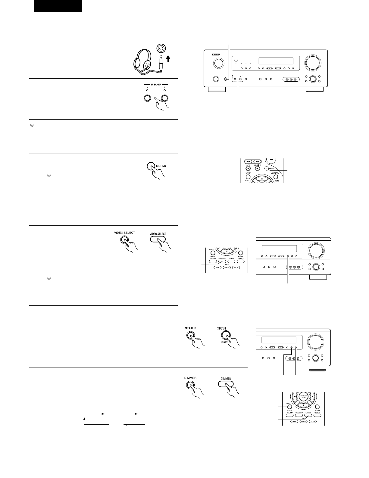
Affichage du panneau avant
• Les descriptions de fonctionnement de l’appareil sont
également affichées sur l’affichage du panneau avant. De
plus, l’affichage peut être commuté pour vérifier l’état de
fonctionnement pendant la lecture d’une source en
appuyant sur la touche STATUS.
Utilisation de la fonction de réduction d’intensité d’éclairage
• Utiliser cette fonction pour modifier la luminosité de
l’affichage.
La luminosité de l’affichage change en quatre paliers (clair,
moyen, sombre et éteint) en appuyant sur la touche
DIMMER de la principale.
Lecture simultanée
Utiliser ce commutateur pour
contrôler une source vidéo
autre que la source audio.
Appuyer répétitivement sur
la touche VIDEO SELECT
jusqu’à ce que la source
désirée apparaisse sur l’affichage.
Cancelling simulcast playback.
•
Sélectionner “SOURCE” à l’aide de la touche de sélection vidéo.
• Commuter la source de programme au composant
connecté aux prises d’entrée vidéo.
76
FRANCAIS
[3] Désactivation provisoire du son (sourdine)
1
Utiliser cette fonction pour désactiver
momentanément la sortie audio.
Appuyer sur la touche MUTING.
Annulation du mode MUTING.
• Appuyer à nouveau sur la
touche MUTING.
• La sourdine sera également annulée lorsque le MASTER
VOL est augmenté ou diminué.
[4]
Combinaison du son actuellement en cours de reproduction avec l’image désirée
1
[5] Vérification de la source programme actuellement en cours de reproduction, etc.
1
(Unité principale) (Unité de
télécommande)
1
1
2
2 1
(Unité principale) (Unité de
télécommande)
1
1
2
(Unité principale)
BRIGHT MEDIUM
OFF
DIM
(Unité de
télécommande)
(Unité de télécommande)
[2] Ecoute avec casque REMARQUE:
Afin d’éviter une perte de l’ouïe, ne pas augmenter excessive ment le
niveau du volume lors de l’utilisation d’écouteurs.
2
1
Connecter le casque à la prise
PHONES du panneau avant.
1
PHONES
2
Appuyer sur le touche SPEAKER A et B
pour éteindre l’enceinte choisie.
ATTENTION: Aucun son n’est produit à la sortie casque lorsque
les enceintes A et B sont activées.
(Unité principale)
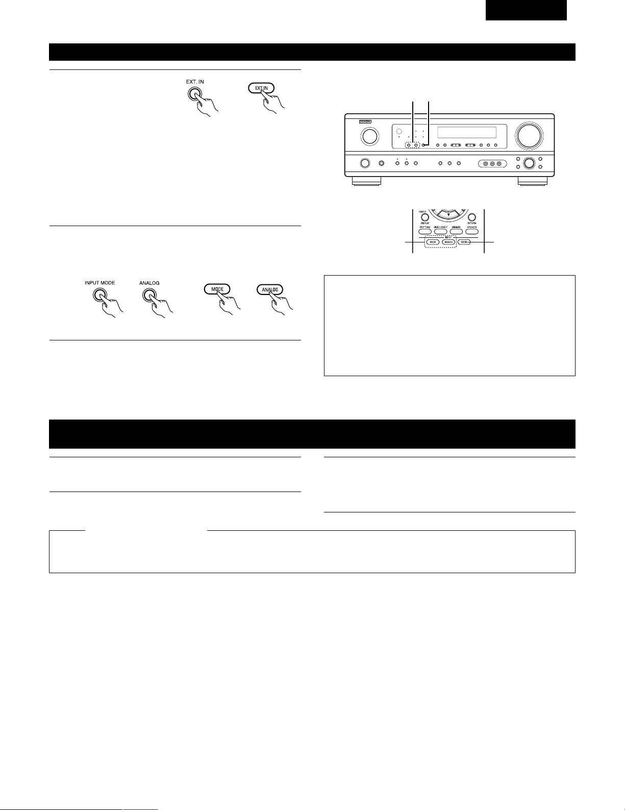
Passer au mode d’entrée
externe (EXT. IN).
Appuyer sur EXT. IN pour
changer l’entrée externe.
Une fois cette sélection effectuée, les signaux d’entrée,
connectés aux canaux FL (avant gauche), FR (arrière droit), C
(central), SL (surround gauche) et SR (surround droit) des
jacks EXT.IN, sont envoyés directement aux systèmes
d’enceinte avant (gauche et droit), central et surround (gauche
et droit) sans passer par les circuits surround. En plus, l’entrée
du signal vers la prise SW (subwoofer) est dirigée sur la prise
PRE OUT SUBWOOFER.
77
FRANCAIS
Lecture en utilisant les prises d’entrée externe (EXT. IN)
1
(Unité principale)
(Unité de télécommande)
2
Annulation du mode d’ entrée externe
Pour annuler le réglage de l’entrée externe (EXT. IN), appuyez
sur le bouton INPUT MODE (AUTO, PCM, DTS) ou ANALOG
pour choisir le mode d’entrée souhaîté. (Voir page 74).
(Unité de télécommande)
(Unité principale)
• Lorsque le mode d’entrée est réglé sur l’entrée externe (EXT. IN) le
mode de lecture (STEREO, DOLBY/DTS SURROUND, 5CH
STEREO ou DSP SIMULATION) ne peut pas être sélectionné.
REMARQUES:
• Dans les modes de lecture autres que le mode d’entrée externe,
les signaux connectés aux prises EXT. IN ne peuvent pas être
lus. En outre, les signaux ne peuvent pas être envoyés des
canaux non connectés aux prises d’entrée.
• Le mode d’entrée externe peut être réglé pour toute source
d’entrée. Pour regarder la vidéo tout en écoutant le son,
sélectionner la source d’entrée à laquelle est connecté le signal
vidéo, puis régler ce mode.
2 1
21
Enregistrement d’un programme source
(enregistrement de la source avec contrôle simultané)
1
Suivez les étapes 1 à 3 de la section “Lecture de la source
d’entrée”.
Les signaux de la source sélectionnée avec la touche de sélection de fonction sont transmis simultanément aux prises CDR/TAPE et VCR
REC OUT. Si un total de deux platines à cassettes/magnétoscopes sont connectés et réglés en mode d’enregistrement, la même source
peut être enregistrée simultanément sur chaque platine/magnétoscope.
REMARQUES:
• Le signal AUDIO IN sélectionné à l’aide de la touche de sélection de fonction est envoyé aux prises CDR/TAPE et VCR AUDIO OUT.
• Les signaux numériques ne sont pas sortis par les prises de sortie audio.
2
Démarrer l’enregistrement sur la platine à cassettes ou le
magnétoscope.
Pour les instructions, se rapporter aux instructions
d’utilisation de l’appareil.
Enregistrement simultané
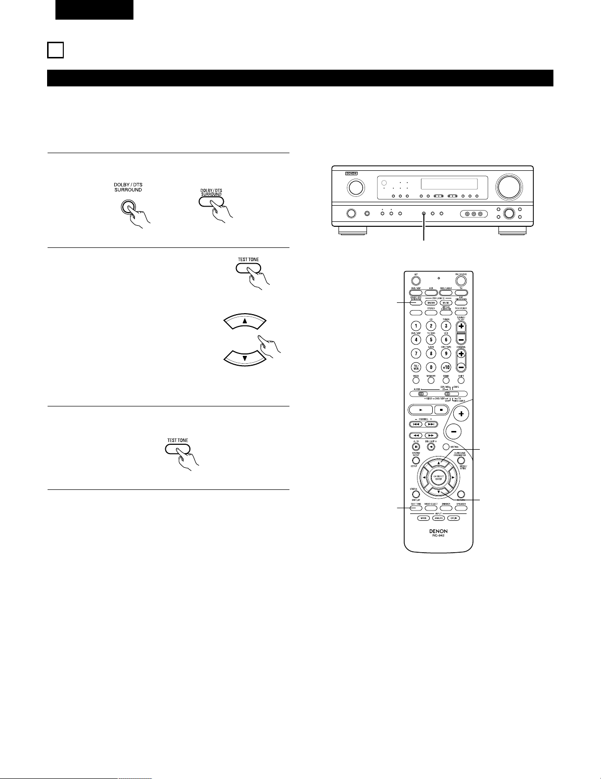
78
FRANCAIS
13
AMBIANCE
Avant la lecture utilisant la fonction d’ambiance
• Avant d’effectuer une lecture avec la fonction d’ambiance sonore, s’assurer d’utiliser auparavant les tonalités de test pour ajuster les réglages
niveaux de reproduction de chacune des enceintes. Ce réglage peut être effectué avec la télécommande (décrite) ci-dessous.
• Les réglages effectués avec les tonalités de test sont valables uniquement avec les modes DOLBY/DTS SURROUND.
Les niveaux de reproduction réglés pour des modes d’ambiance différents sont automatiquement mis en mémoire dans chacun des modes
d’ambiance.
1
Passer aux modes DOLBY/DTS SURROUND (Dolby Pro
Logic II ou Dolby Digital ou DTS).
2
Appuyer sur la touche TEST TONE.
3
Après la fin du réglage, appuyer à nouveau sur la touche TEST
TONE.
(Unité principale) (Unité de télécommande)
(Unité de télécommande)
Les tonalités d’essai sont envoyées
des différentes enceintes. Utiliser les
touches de réglage du volume des
canaux pour ajuster de telle façon que
le volume des tonalités d’essai soit
identique pour toutes les enceintes.
(Unité de télécommande)
1
2
2
2, 3
1
(Unité de télécommande)
REMARQUE: Veuillez vous assurer que le bouton à glissière
de la télécommande est en position “AUDIO”.
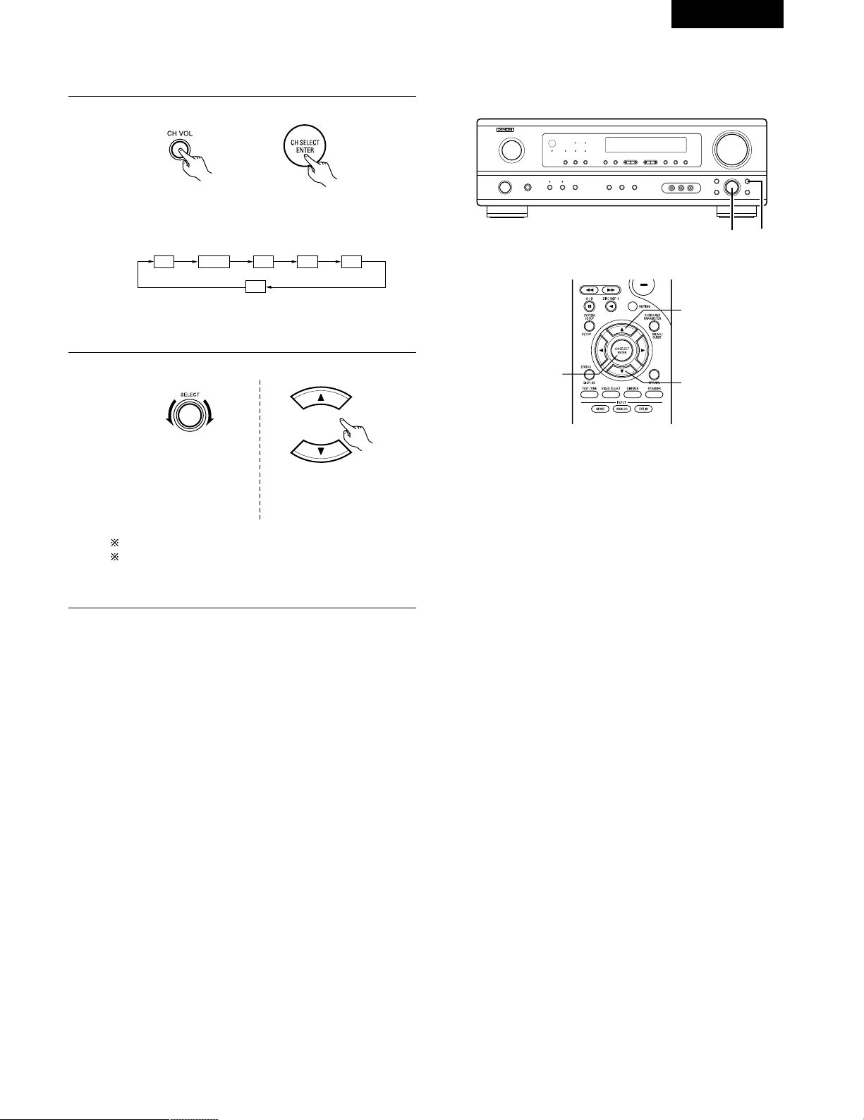
79
FRANCAIS
REMARQUE: Veuillez vous assurer que le bouton à glissière
de la télécommande est en position “AUDIO”.
• Après le réglage utilisant les tonalités d’essai, ajuster les niveaux des canaux en fonction des sources de lecture ou selon votre convenance
personnelle, comme décrit ci-dessous.
1
Sélectionner l’enceinte dont vous voulez ajuster le niveau.
Le canal change de la manière indiquée ci-dessous chaque
fois que la touche est enfoncée.
2
Ajuster le niveau de l’enceinte sélectionnée.
FL CNTR FR SR SL
SW
(Unité principale) (Unité de télécommande)
(Unité principale)
(Unité de télécommande)
2 1
2
2
1
Le réglage par défaut du niveau de canal est de 0 dB.
Le niveau de reproduction de l'enceinte sélectionnée peut
être réglé sur une plage de valeurs allant de +12 à –12 dB
en utilisant les touches SELECT (haut et bas).
Ce réglage n’est possible
que lorsque le canal est
sélectionné par le bouton
CH. VOL de l’appareil.
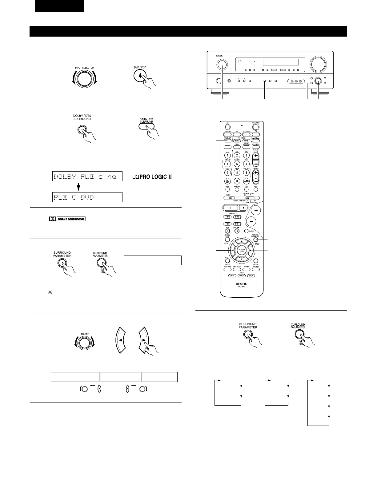
80
FRANCAIS
Pour effectuer cette opération à l'aide de la
télécommande, vérifier que l'interrupteur de sélection de
mode est réglé sur “AUDIO”.
Mode Dolby Surround Pro Logic
II
2
Sélectionner le mode Dolby Surround Pro Logic II.
S’allume
(Unité principale)
(Unité de télécommande)
3
Reproduire une source programme avec la marque
.
• Pour les instructions d’utilisation, se reporter aux manuels
des composants respectifs.
5, 74, 61 2
4, 6
5, 7
1
5, 7
2
4
Sélectionner le mode de paramètrage d'ambiance sonore.
MODE Dolby PL
CINEMA EQ
DEFAULT
MODE CINEMA
CINEMA EQ
DEFAULT
MODE MUSIC
PANORAMA
DIMENSION
CENTER WIDTH
DEFAULT
ou ou
MODE musicMODE cinemaMODE DOLBY PL
1
Sélectionner la fonction se rapportant au composant que vous
désirez écouter.
Exemple: DVD
(Unité principale)
(Unité de télécommande)
Affichage
(Unité principale)
(Unité de télécommande)
MODE cinema
Affichage
5
Sélectionner le meilleur mode pour la souce.
(Unité principale)
(Unité de télécommande)
6
Régler les paramètres d'ambiance sonore selon le mode.
(Unité principale)
(Unité de télécommande)
• Le mode se commute à chaque pression sur la touche
comme indiqué ci-dessous.
• Le témoin Dolby Pro Logic s’allume.
Le mode Dolby Surround Pro
Logic II Cinema ou Music peut
être choisi directement en
appuyant sur la touche CINEMA
ou MUSIC de la télécommande
pendant la lecture en mode
Dolby Surround Pro Logic II.
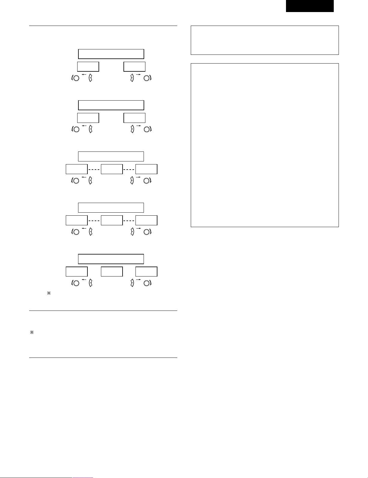
81
FRANCAIS
REMARQUE:
• Pendant le réglage des paramètres, l’affichage va revenir à son
état d’origine plusieurs secondes après que le dernier bouton ait
été enfoncé, ce qui terminera le réglage.
7
Régler les paramétrages d'ambiance sonore.
• Réglage CINEMA EQ
ON OFF
ou ou
CINEMA EQ OFF
• Réglage PANORAMA
ON OFF
ou ou
PANORAMA OFF
• Réglage DIMENSION
0 3 6
ou ou
DIMENSION 3
• Réglage CENTER WIDTH
0
CENTER WIDTH 3
4 7
ou ou
• Réglage DEFAULT
YES Y/N NO
ou ou
DEFAULT Y/N
Sélectionner “Yes” pour retourner aux valeurs d'usine par
défaut.
Paramètres d’ambiance q
Mode Pro Logic II:
Le mode Cinéma peut être utilisé pour led émissions de télévision
en stéréo et tous les programmes enregistrés en Dolby Surround.
Le mode Music est recommandé comme mode standard pour les
systèmes musicaux à son automatique (pas de vidéo) et optionnel
pour le système A / V.
Le mode Dolby PL offre le même traitement d’ambiance robuste
que le mode Pro Logic d’origine si le contenu de la source n’est
pas de qualité optimale.
Sélectionner un des modes (“Cinema”, “Music” ou “Dolby PL”).
Commande de Panorama:
Ce mode étend l’image stéréo frontale pour inclure les enceintes
d’ambiance ou un effet “wraparound” excitant avec une
exposition d’image latérale.
Sélectionner “OFF“ ou “ON“.
Commande de dimension:
Cette commande ajuste progressivement le champ sonore vers
l’avant ou l’arrière.
La commande peut être réglée en 7 étapes de 0 à 6.
Commande de largeur centrale:
Cette commande ajuste l’image centrale de sorte qu’elle puisse
être entendue uniquement de l’enceinte centrale; uniquement des
enceintes gauche/droite comme une image fantôme ou des trois
enceintes frontales pour varier les degrés d’enregistrement.
La commande peut être réglée en 8 étapes de 0 à 7.
Arrêter d’appuyer sur les touches après avoir terminé d’effectuer
les paramétrages d’ambiance sonore. Après quelques secondes,
l’affichage normal ré-apparaît et les réglages que vous avez fait
sont automatiquement ajustés.
Appuyer sur la touche SURROUND PARAMETER pour passer au
réglage CINEMA EQ, PANORAMA.
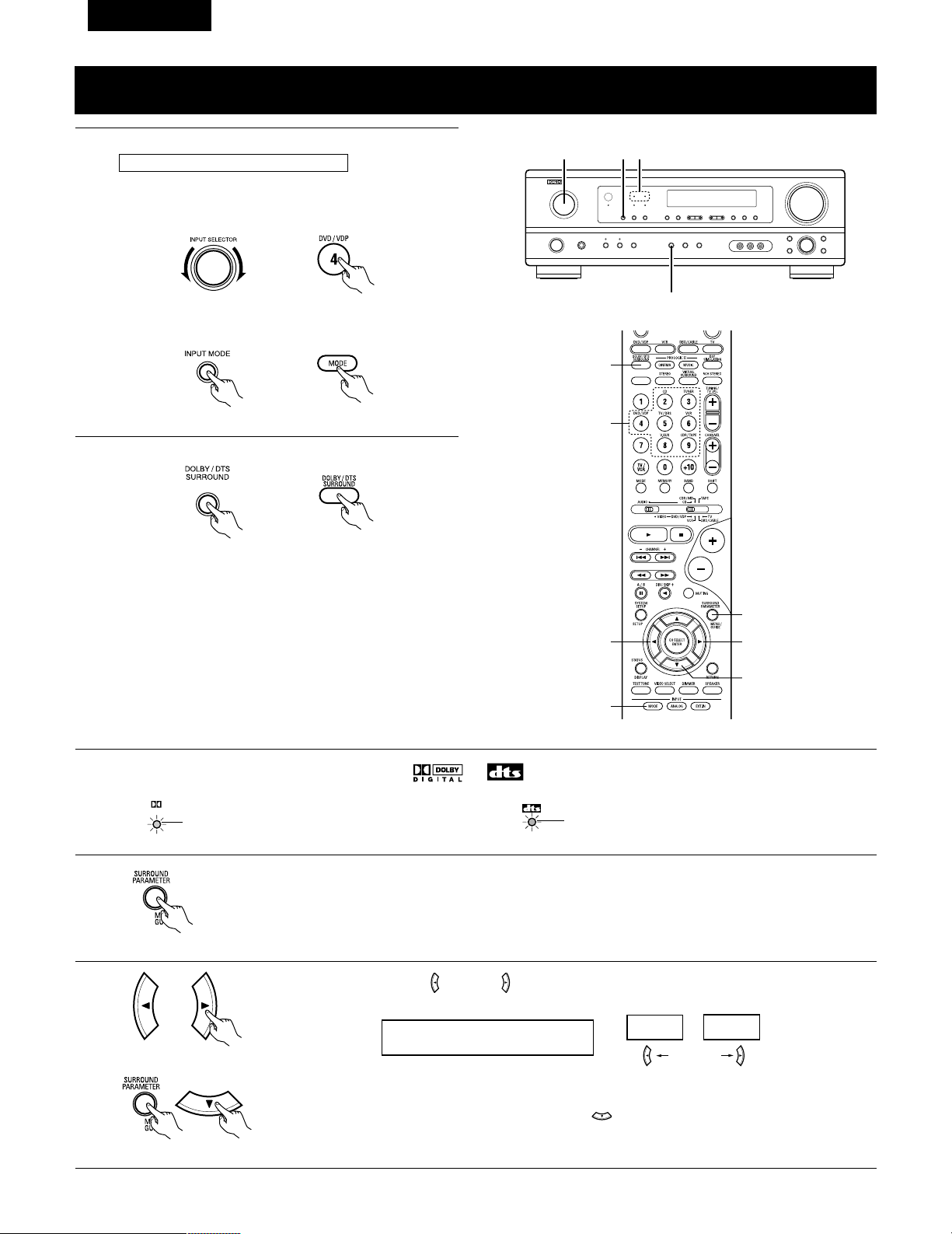
82
FRANCAIS
Mode Dolby Digital (uniquement avec entrée numérique) et le mode d’ambiance DTS
(uniquement avec entrée numérique)
1
Sélectionner la source d’entrée.
q Sélectionner une source d’entrée réglée à numérique
(COAXIAL/OPTICAL) (voir page 67).
(Unité principale) (Unité de télécommande)
w Régler le mode d’entrée à “AUTO” ou “DTS”.
2
Sélectionner le mode Dolby/DTS Surround.
(Unité de télécommande)
3
Reproduire une source programme avec la marque , .
• Le témoin Dolby Digital s’allume en
cas de reproduction de sources Dolby
Digital.
DIGITAL
S’allume
2
1 1 3
4, 5, 6, 7, 8
5, 6, 7, 8
5, 6, 7, 8
5, 6, 7, 8
1
1
2
Reproduire avec une entrée numérique
• Le témoin DTS s’allume en cas de
reproduction de sources DTS.
S’allume
4
Régler le paramètre d’ambiance en fonction de la source.
Appuyer tout d’abord sur la touche SURROUND PARAMETER.
(Unité de télécommande)
REMARQUE: Veuillez vous assurer que le bouton à glissière de la télécommande est en position “AUDIO”.
Appuyer sur la touche SURROUND PARAMETER ou (bas) pour passer au réglage D. COMP.
Utiliser les touches (gauche) et (droit) pour régler CINEMA EQ.
5
Exemple: DVD
(Unité principale) (Unité de télécommande)
CINEMA EQ OFF
ON
OFF
touche (gauche) touche (droit)
(Initial)
(Unité de télécommande)
(Unité de télécommande)
(Unité principale)
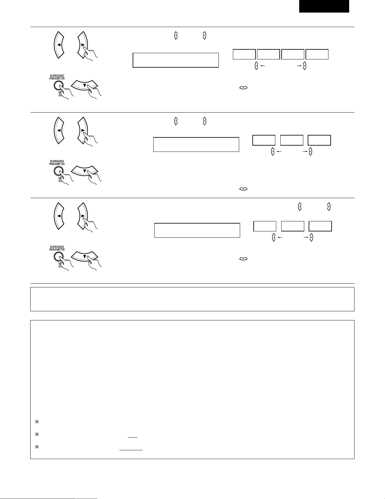
83
FRANCAIS
6
Utiliser les touches (gauche) et (droit) pour régler la compression de la gamme dynamique (D.COMP).
D.COMP. OFF
OFF LOW MID HIGH
Appuyer sur la touche SURROUND PARAMETER ou (bas) pour passer au réglage LFE.
touche (gauche) touche (droit)
(Unité de télécommande)
(Unité de télécommande)
7
Utiliser les touches (gauche) et (droit) pour régler le niveau LFE.
LFE 0dB
-10dB
-5dB 0dB
• Le niveau peut être ajusté en unités de 1 dB de -10 à 0 dB.
Régler au niveau désiré en fonction des systèmes d’enceintes utilisés et de la source à reproduire.
Appuyer sur la touche SURROUND PARAMETER ou (bas) pour passer au réglage par défaut.
(Unité de télécommande)
(Unité de télécommande)
REMARQUE
Ce paramètre n’est pas affiché pendant la lecture DTS.
8
Pour remettre le système en configuration par défaut, utiliser les touches (gauche) et (droit) pour que
“Yes” s’affiche.
DEFAULT Y/N
YES
Y/N NO
Appuyer sur la touche SURROUND PARAMETER ou (bas) pour passer au réglage CINEMA EQ.
touche (gauche) touche (droit)
(Unité de télécommande)
(Unité de télécommande)
Paramètres d’ambiance w
CINEMA EQ. (Egaliseur Cinéma):
La fonction Cinema EQ diminue doucement le niveau des fréquences très élevées, compensant les pistes sonores de films à son trop éclatant.
Sélectionner cette fonction si le son en provenance des enceintes avant est trop éclatant. Cette fonction n’est opérationnelle que dans les
modes Dolby Pro Logic, Dolby Digital et DTS Surround. (Les mêmes réglages sont effectués pour tous les modes de fonctionnement.)
D.COMP. (Compression de gamme dynamique):
Les pistes sonores de films ont une formidable gamme dynamique (contraste entre sons très doux et très forts). Pour écouter tard la nuit ou
chaque fois que le niveau sonore maximum est plus bas que d’habitude, la compression de gamme dynamique vous permet d’entendre tous
les sons de la piste sonore (mais avec une gamme dynamique réduite). (Ceci n’est opérationnel qu’en cas de reproduction de sources
programmes enregistrées en Dolby Digital.) Sélectionner un des quatre paramètres (“OFF”, “LOW”, “MID” (moyen) ou “HIGH” (haut)). Régler
à “OFF” pour une écoute normale.
LFE (Effet de basse fréquence):
Source programme et gamme de réglage:
1. Dolby Digital: –10 dB à 0 dB
2. DTS Surround: –10 dB à 0 dB
Lorsque le logiciel encodé avec Dolby Digital est reproduit, il est recommandé que le niveau LFE (LFE LEVEL) soit réglé à 0 dB pour
une lecture correcte avec Dolby Digital.
Lors de la lecture de programme de film au format DTS, il est recommandé de réglé le niveau LFE LEVEL sur 0 dB pour corriger la
lecture DTS.
Lors de la lecture de programme musicaux au format DTS, il est recommandé de réglé le niveau LFE LEVEL sur -10 dB pour corriger
la lecture DTS.
(Initial)
(Initial)
touche (gauche) touche (droit)
REMARQUE:
• Pendant le réglage des paramètres, l’affichage va revenir à son état d’origine plusieurs secondes après que le dernier bouton ait été enfoncé,
ce qui terminera le réglage.
84
FRANCAIS
14
SIMULATION D’AMBIANCE DSP
• Ce appareil est équipé d’un DSP (processeur numérique de signal) de haute précision qui utilise le traitement des signaux numériques pour
recréer de manière synthétique le champ sonore. Un des 7 modes d’ambiance préréglés peut être sélectionné en fonction de la source
programme, et les paramètres peuvent être ajustés en fonction des conditions de la salle d’écoute pour obtenir un son puissant et plus réaliste.
Ces modes d’ambiance peuvent également être utilisés pour des sources programmes pas enregistrées en Dolby Surround Pro Logic ou Dolby
Digital.
Modes d’ambiance et leurs caractéristiques
1
2
3
4
5
6
7 VIRTUAL
ROCK ARENA
JAZZ CLUB
VIDEO GAME
MONO MOVIE
(REMARQUE 1)
MATRIX
5CH STEREO
Sélectionner ce mode pour profiter d’un champs sonore virtuel, qui est créé par les enceintes à 2 canaux situées
sur le devant.
Utiliser ce mode pour obtenir la sensation d’un concert en direct dans une arène avec des sons réfléchis venant
de toutes les directions.
Ce mode crée le champ sonore d’un café-concert avec un plafond bas et des murs solides. Ce mode donne au
jazz un réalisme très net.
Utiliser cette possibilité pour apprécier les jeux vidéo.
Sélectionner ceci en regardant des films monauraux avec une impression d’expansion plus forte.
Sélectionner ceci pour accentuer l’impression d’expansion de sources musicales enregistrées en stéréo.
Des signaux consistant en un composant différent des signaux d’entrée (le composant qui assure l’impression
d’expansion) traités pour retard sont sortis par le canal d’ambiance.
Dans ce mode, les signaux du canal avant gauche sont sortis par le canal d’ambiance gauche, les signaux du canal
avant droit par le canal d’ambiance droit, et le même composant (en phase) des canaux gauche et droit par le canal
central. Ce mode donne le son d’ambiance de toutes les enceintes, mais sans effet directionnel, et il agit avec
toute source de programme stéréo.
En fonction de la source de programme lue, l’effet peut ne pas être perceptible.
Si cela se produit, essayer d’autres modes d’ambiance sans se soucier des noms, pour créer un champ sonore adapté à vos goûts.
REMARQUE 1: En cas de reproduction de sources enregistrées en monaural, le son sera unilatéral si des signaux ne sont entrés que vers un
canal (gauche ou droit), donc entrer des signaux vers les deux canaux. Si vous avez un composant source ayant une seule sortie
audio (camescope monophonique, etc.), procurez-vous un câble d’adaptateur “Y” pour partager la sortie mono en deux sorties,
et connectez aux entrées L et R.
Mémoire personnelle Plus
Cet ensemble est équipé d’une fonction de mémoire personnelle qui mémorise automatiquement les modes d’ambiance et les modes
d’entrée sélectionnés pour les différentes sources d’entrée. Lorsque la source d’entrée est commutée, les modes réglés pour cette source à
la dernière utilisation sont automatiquement rappelés.
Les paramètres d’ambiance, les réglages de commandes de tonalité et l’équilibre du niveau de lecture pour les différents canaux de sortie
sont mémorisés pour chaque mode d’ambiance.
REMARQUE:
Seuls les mode STEREO peuvent être utilisés en cas de reproduction de signaux PCM ayant une fréquence d’échantillonnage de 96 kHz
(tels que de disques vidéo DVD contenant des sons 24 bits, 96 kHz). Si ces signaux sont entrés pendant la lecture dans un des autres
modes d’ambiance, le mode change automatiquement à STEREO.
Si des signaux DTS sont entrés en cours de lecture dans le mode d’ambiance VIRTUAL, le mode commute automatiquement sur STEREO.
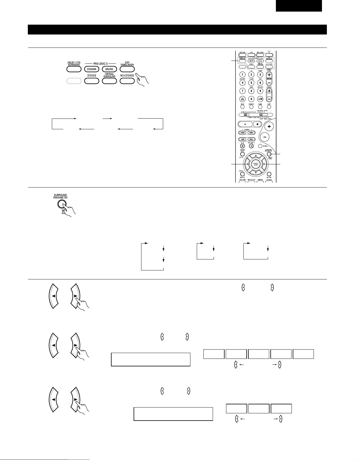
85
FRANCAIS
Simulation d’ambiance DSP
1
Sélectionner le mode d’ambiance pour le canal d’entrée.
(Unité de télécommande)
Le mode d’ambiance commute dans l’ordre suivant chaque
fois que la touche DSP SIMULATION est enfoncée:
2
33
1
2
Pour enter en mode de réglage de paramètre d’ambiance appuyer sur la touche SURROUND PARAMETER.
• Le paramètre d’ambiance commute dans l’ordre suivant chaque fois que la touche SURROUND PARAMETER
est enfoncée dans les différents modes d’ambiance.
MONO MOVIE ROCK ARENA
JAZZ CLUBVIDEO GAME
MATRIX
• Pour utiliser les modes surround et régler leurs paramètres à l’aide de la télécommande.
(Unité de télécommande)
3
Utiliser les touches (gauche) et (droit) pour sélectionner la dimension de la pièce.
ROOM SIZE MED
LARGEMED-LMEDMED-SSMALL
touche (gauche) touche (droit)
(Unité de télécommande)
(1) ROOM SIZE
Afficher le paramètre à ajuster, ensuite utiliser les touches (gauche) et (droite) pour le régler.
ROOM SIZE
EFFECT
DEFAULT
EFFECT LEVEL
DEFAULT
DELAY
DEFAULT
• ROCK ARENA
• JAZZ CLUB
• VIDEO GAME
• MONO MOVIE
• MATRIX • VIRTUAL
(Initial)
Utiliser les touches (gauche) et (droit) pour régler le niveau de l’effet.
EFFECT LEVEL 10
15101
touche (gauche) touche (droit)
(Unité de télécommande)
(2) EFFECT LEVEL
(Initial)
(Unité de télécommande)
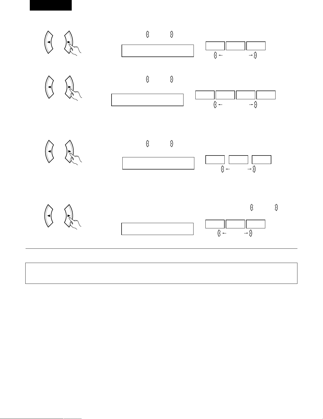
86
FRANCAIS
Utiliser les touches (gauche) et (droit) pour régler le délai.
DELAY 30ms
110ms30ms0ms
touche (gauche) touche (droit)
(Unité de télécommande)
(3) DELAY TIME
(Unité de télécommande)
(6) DEFAULT
Pour remettre le système en configuration par défaut, utiliser les touches (gauche) et (droit) pour que
“Yes” s’affiche.
DEFAULT Y/N
NOY/NYES
touche (gauche) touche (droit)
(Initial)
Utiliser les touches (gauche) et (droit) pour régler la compression de la gamme dynamique (D.COMP).
D.COMP. OFF
OFF LOW MID HIGH
(Unité de télécommande)
REMARQUE:
Ce paramètre est pas affiché pendant la lecture DOLBY DIGITAL.
(Initial)
(4) D. COMP.
touche (gauche) touche (droit)
Utiliser les touches (gauche) et (droit) pour régler le niveau LFE.
LFE 0dB
-10dB
-5dB 0dB
touche (gauche) touche (droit)
(Unité de télécommande)
REMARQUE:
Ce paramètre est pas affiché pendant la lecture DOLBY DIGITAL.
(Initial)
(5) LFE
REMARQUE:
• Pendant le réglage des paramètres, l’affichage va revenir à son état d’origine plusieurs secondes après que le dernier bouton ait été enfoncé,
ce qui terminera le réglage.
Appuyer sur la touche SURROUND PARAMETER pour passer au réglage ROOM SIZE, DELAY, EFFECT LEVEL.
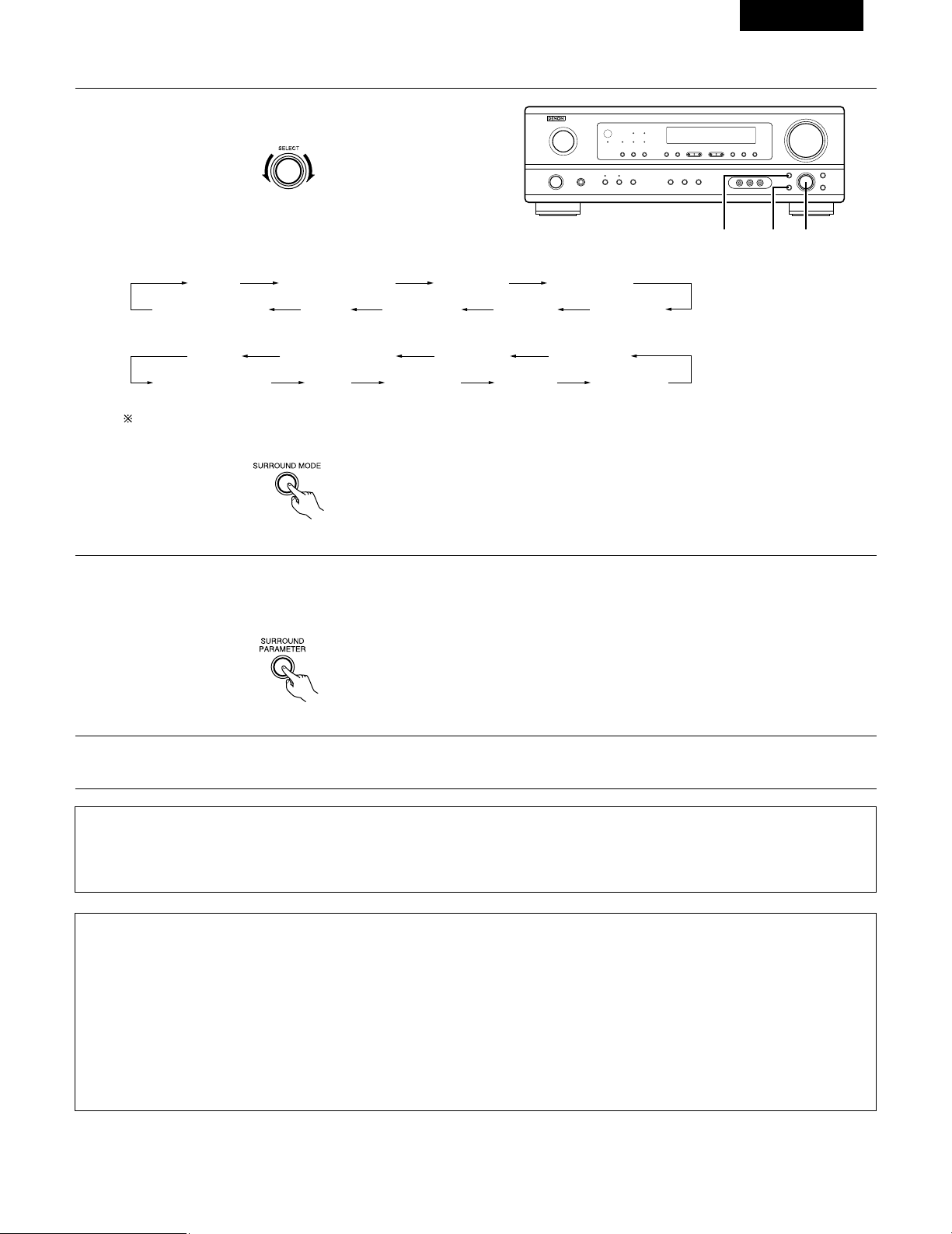
87
FRANCAIS
REMARQUE:
• Lors de la lecture de signaux numériques PCM ou des signaux analogiques dans les modes d’ambiance 5CH STEREO, ROCK ARENA, JAZZ
CLUB, VIDEO GAME, MONO MOVIE ou MATRIX et lorsque le signal d’entrée commute à un signal numérique codé en Dolby Digital, le
mode d’ambiance Dolby est commuté automatiquement. Lorsque le signal d’entrée commute à un signal DTS, le mode commute
automatiquement au mode d’ambiance DTS.
1
Tourner le bouton SELECT pour sélectionner le mode
surround.
(Unité principale)
• Lorsqu’il est tourné dans le sens horaire
2
Appuyer sur la touche SURROUND PARAMETER.
Appuyer sur la touche de paramètre d’ambiance et la maintenir enfoncée pour sélectionner le paramètre à définir.
• Les paramètres qui peuvent être définis sont différents pour les différents modes d’ambiance. (Se référer à “Modes et paramètres
d’ambiance” à la page 88.)
STEREO DOLBY PRO LOGIC II
5CH STEREO
MONO MOVIE
JAZZ CLUB ROCK ARENAVIDEO GAMEMATRIXVIRTUAL SURROUND
STEREO DOLBY PRO LOGIC II
5CH STEREO
MONO MOVIE
JAZZ CLUB ROCK ARENAVIDEO GAMEMATRIXVIRTUAL SURROUND
• Pour utiliser les modes surround et régler leurs paramètres à partir du panneau de commande de l’unité principale.
1, 321
• Lorsqu’il est tourné dans le sens anti-horaire
Pour sélectionner le mode d’ambiance pendant le réglage des paramètres d’ambiance, le volume du canal ou la commande de tonalité,
appuyer sur la touche de mode d’ambiance, puis utiliser le sélecteur.
(Unité principale)
(Unité principale)
3
Afficher le paramètre que l’on souhaite régler et tourner ensuite le bouton SELECT pour le régler.
Paramètres d’ambiance e
ROOM SIZE (Taille de piece):
Ceci règle la taille du champ sonore.
Il y a cinq réglages: “small” (petit), “med.s” (moyen–petit), “medium” (moyen), “med.l” (moyen–large) et “large”. “small” recrée un petit
champ sonore, “large” un large champ sonore.
EFECT LEVEL (Niveau d’effet):
Ceci règle la force de l’effet d’ambiance.
Le niveau peut être réglé en 15 étapes de 1 à 15. Lorsque le mode d’ambiance est réglé sur “VIRTUAL”, le niveau d’effet peut être réglé par
pas de 1 à 10. Baisser le niveau si le son semble déformé.
DELAY TIME (Temps de retard):
Dans le mode de matrice uniquement, le temps de retard peut être réglé dans la gamme de 0 à 110 ms.
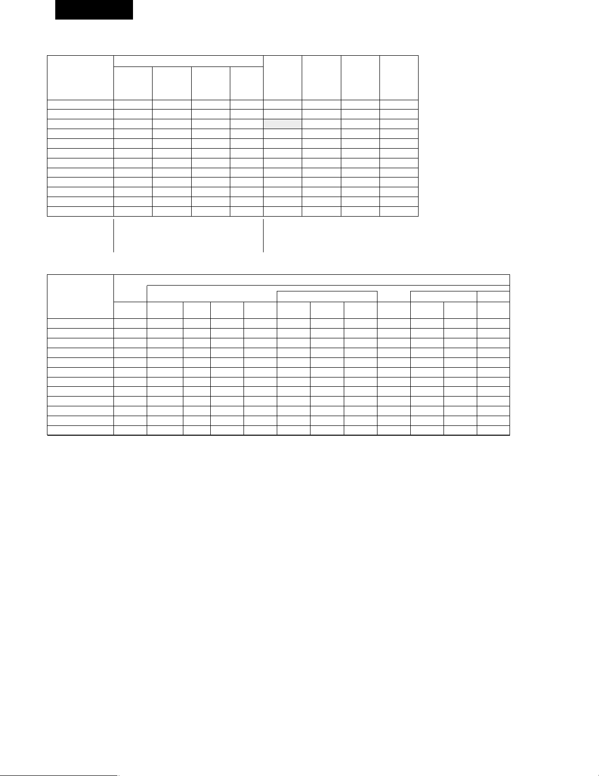
C
E
C
*
C
E
E
E
E
E
E
E
C
88
FRANCAIS
2 Modes d’ambiance et paramètres
Sortie de canal
B
B
B
B
B
B
B
B
B
B
B
B
SUB-
WOOFER
E
B
B
B
B
B
B
B
B
B
B
E
SURROUND
L/R
E
B
B
B
B
B
B
B
B
B
B
E
CENTER
C
C
C
C
C
C
C
C
C
C
C
C
FRONT L/R
Mode
STEREO
EXTERNAL INPUT
DOLBY PRO LOGIC
II
DOLBY DIGITAL
DTS SURROUND
5CH STEREO
ROCK ARENA
JAZZ CLUB
VIDEO GAME
MONO MOVIE
MATRIX
VIRTUAL
C : Signal
E : Pas de signal
B : Activé ou désactivé par réglage de configuration
d’enceinte
En cas de
reproduction
de signaux
Dolby Digital
En cas de
reproduction
de signaux
DTS
C
E
E
E
C
E
E
E
E
E
E
C
Paramètre (les valeurs par défaut sont indiquées entre parenthèses)
Signaux Dolby Digital
D.COMP.
C (OFF)
E
C (OFF)
C (OFF)
E
E
E
E
E
E
E
C (OFF)
E
E
E
E
E
E
E
E
E
E
C
(30msec)
E
DELAY
TIME
E
E
E
E
E
E
C (10)
C (10)
C (10)
C (10)
E
C (10)
EFFECT
LEVEL
E
E
E
E
E
E
C
(Medium)
C
(Medium)
C
(Medium)
C
(Medium)
E
E
ROOM
SIZE
C (0dB)
C (0dB)
C (0dB)
C (0dB)
C (0dB)
C (0dB)
C (0dB)
C (0dB)
C (0dB)
C (0dB)
C (0dB)
C (0dB)
TONE
CONTROL
Mode
STEREO
EXTERNAL INPUT
DOLBY PRO LOGIC
II
DOLBY DIGITAL
DTS SURROUND
5CH STEREO
ROCK ARENA
JAZZ CLUB
VIDEO GAME
MONO MOVIE
MATRIX
VIRTUAL
C :Réglable
E : Pas ajustable
LFE
C (0dB)
E
C (0dB)
C (0dB)
–
E
E
E
E
E
E
C (0dB)
En cas de
reproduction
de signaux
PCM
(96k)
C ( C )
E
C
E
E
C
C
C
C
C
C
C
En cas de
reproduction
de signaux
ANALOG
C
C
C
E
E
C
C
C
C
C
C
C
C : Activé
E :Désactivé
E
E
C
(CINEMA)
E
E
E
E
E
E
E
E
E
MODE
E
E
C (OFF)
E
E
E
E
E
E
E
E
E
PANORAMA
E
E
C (3)
E
E
E
E
E
E
E
E
E
DIMENSION
E
E
C (0)
E
E
E
E
E
E
E
E
E
CENTER
WIDTH
E
E
C (OFF)
C (OFF)
C (OFF)
E
E
E
E
E
E
E
CINEMA
EQ
LFE
C (0dB)
E
–
–
C (0dB)
E
E
E
E
E
E
E
Signaux DTS
Pour l’mode PRO LOGIC II MUSIC
PARAMÈTRES D’AMBIANCE
* Seulement pour le contenu de 2 ch.
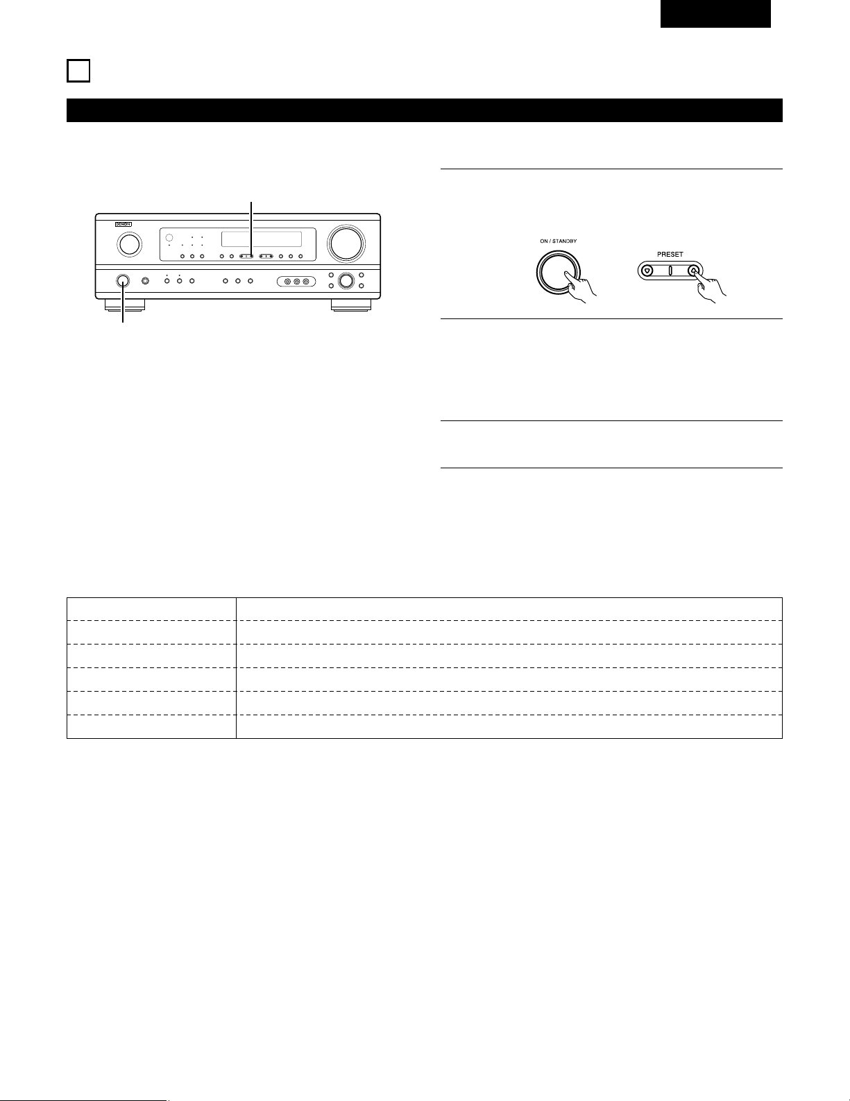
89
FRANCAIS
Lorsque l’ interrupteur d’alimentation de l’appareil principal
est activé en même temps que le touche de réglage PRESET
DD
, l’appareil commence automatiquement à chercher des
station de radio FM.
REMARQUES:
• Si une station FM ne peut pas être automatiquement préréglée à
cause d’une mauvaise réception, utiliser l’opération de
“Syntonisation manuelle” pour syntoniser la station, puis la
prérégler en utilisant l’opération de “Mémoire préréglée” manuelle.
• Pour interrompre cette fonction, appuyer le touche d’alimentation.
15
ECOUTER DE LA RADIO
Mémoire préréglée automatique
1
2
Lorsque la première station de radiodiffusion en FM est
trouvée, cette station est stockée dans la mémoire préréglée
au canal A1. Les stations suivantes sont automatiquement
stockées dans l’ordre aux canaux préréglés A2 à A8, B1 à B8,
C1 à C8, D1 à D8 et E1 à E8 pour un maximum de 40
stations.
3
Le canal A1 est syntonisé après la fin de l’opération de
mémoire préréglée automatique.
1
1
Cet appareil est équipé d’une fonction de recherche automatique d’émissions de radiodiffusion en FM et de leur stockage dans la mémoire
préréglée.
2 VALEUR PAR DEFAUT
AUTO TUNER PRESETS
A1 ~ A8 87.5/89.1/98.1/107.9/90.1/90.1/90.1/90.1 MHz
B1 ~ B8 520/600/1000/1400/1500/1710 kHz/90.1/90.1 MHz
C1 ~ C8 90.1 MHz
D1 ~ D8 90.1 MHz
E1 ~ E8 90.1 MHz
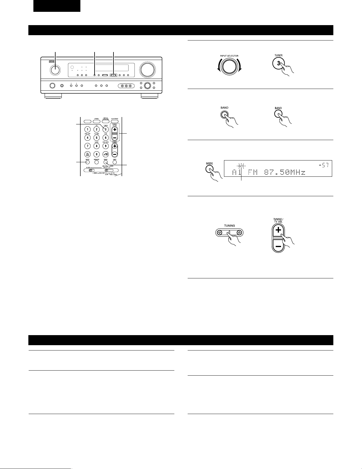
90
FRANCAIS
Appuyer sur la touche TUNING
DD
(+) (augmentation de
syntonisation) ou TUNING
HH
(–) (diminution de syntonisation)
pour syntoniser la station désirée.
La fréquence change continuellement lorsque la touche est
maintenue enfoncée.
Syntonisation manuelle
1
Régler la fonction d’entrée à “TUNER”.
2
En regardant l’affichage, appuyer sur la touche BAND (bande)
pour sélectionner la bande désirée (AM ou FM).
3
Appuyer sur la touche MODE (mode) pour régler le mode de
syntonisation manuelle. Vérifier que le témoin “AUTO” de
l’affichage s’éteint.
4
REMARQUE:
• Lorsque le mode de syntonisation manuelle est réglé, les émissions en stéréo FM sont reçues en mode monaural et le témoin “STEREO”
s’éteint.
Syntonisation automatique
1
Régler la source d’entrée sur “TUNER”.
2
En regardant l’affichage, appuyer sur la touche BAND (bande)
pour sélectionner la bande désirée (AM ou FM).
3
Appuyer sur la touche MODE (mode) pour régler le mode de
syntonisation automatique.
Allumé
4
Appuyer sur la touche TUNING
DD
(+) (augmentation de
syntonisation) ou TUNING
HH
(–) (diminution de syntonisation).
• La recherche automatique commence, puis s’arrête
lorsqu’une station est syntonisée.
REMARQUE:
• Tout en étant en mode de syntonisation automatique sur la bande
FM, le témoin “STEREO” s’allume sur l’affichage lorsqu’une
émission stéréo est syntonisée.
Aux fréquences ouvertes, le bruit est mis en sourdine et les
témoins “TUNED” et “STEREO” s’éteignent.
2 41
3
1
4
2
(Unité de télécommande)
(Unité principale)
(Unité principale) (Unité de télécommande)
(Unité de télécommande)(Unité principale)
(Unité de télécommande)
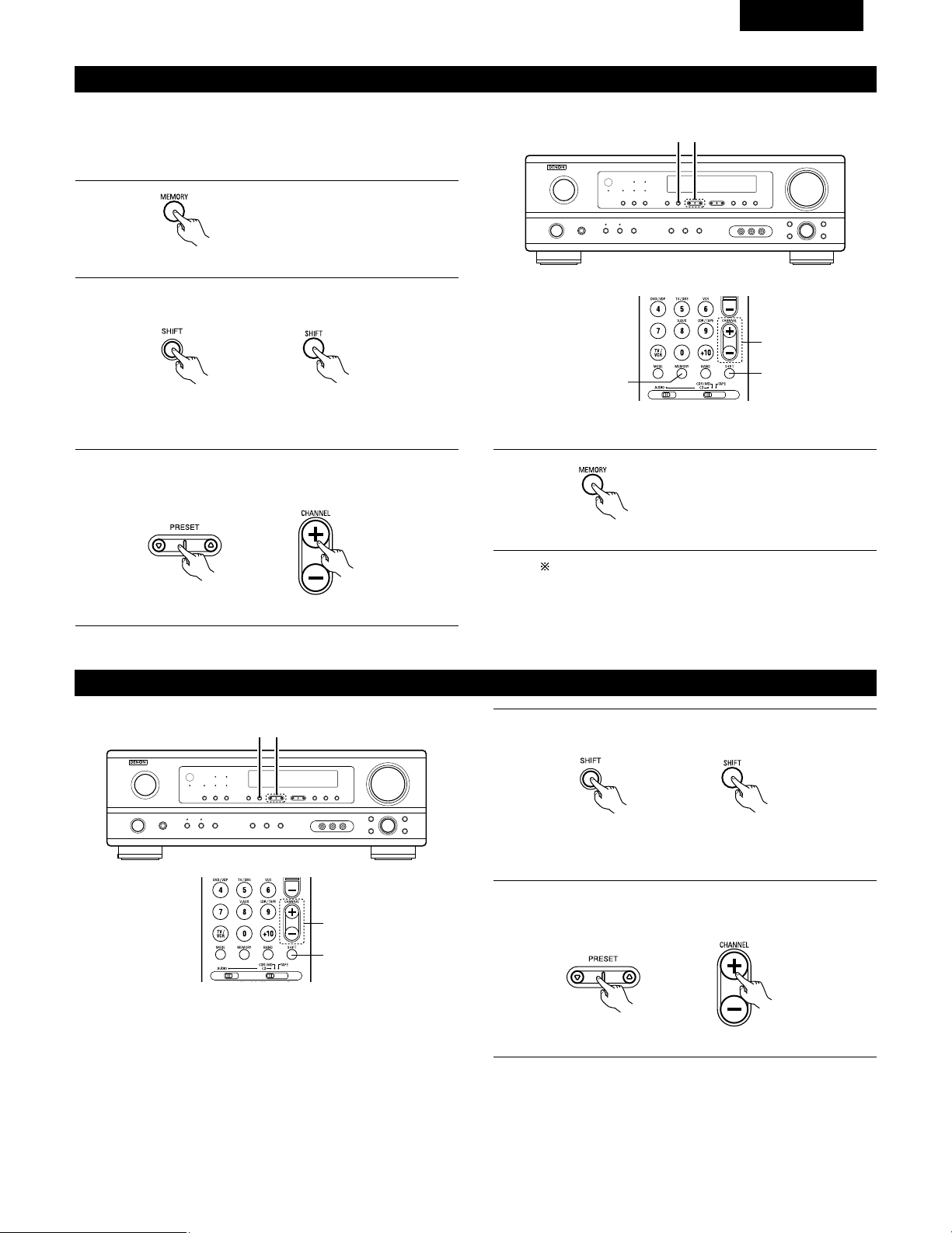
91
FRANCAIS
Stations préréglée
1
Appuyer sur la touche MEMORY
(mémoire).
2
Appuyer sur la touche SHIFT, et sélectionner le bloc de
mémoire désiré (A à E).
(Unité principale) (Unité de télécommande)
3
Appuyer sur la touche PRESET
DD
(+) (augmentation de
préréglage) ou PRESET
HH
(–) (diminution de préréglage) pour
sélectionner le canal préréglé désiré (1 à 8).
(Unité principale) (Unité de télécommande)
4
Appuyer de nouveau sur la touche
MEMORY (mémoire) pour stocker
la station dans la mémoire
préréglée.
Pour prérégler d’autres canaux, répéter les étapes 1 à 4.
Un total de 40 stations de radiodiffusion peut être
préréglées – 8 stations (canaux 1 à 8) dans chacun des
blocs A à E.
32
1, 4
3
2
Rappel de stations préréglées
Préparatifs:
Utiliser l’opération de “Syntonisation automatique” ou de
“Syntonisation manuelle” pour syntoniser la station à prérégler dans
la mémoire.
(Unité de télécommande)
(Unité de télécommande)
1
En regardant l’affichage, appuyer sur la touche SHIFT pour
sélectionner le bloc de mémoire préréglé.
(Unité principale) (Unité de télécommande)
2
En regardant l’affichage, appuyer sur la touche PRESET
DD
(+)
(augmentation de préréglage) ou PRESET
HH
(–) (diminution de
préréglage) pour sélectionner le canal préréglé désiré.
(Unité principale) (Unité de télécommande)
21
2
1
REMARQUE: Veuillez vous assurer que le bouton à glissière
de la télécommande est en position “AUDIO”.
REMARQUE: Veuillez vous assurer que le bouton à glissière
de la télécommande est en position “AUDIO”.
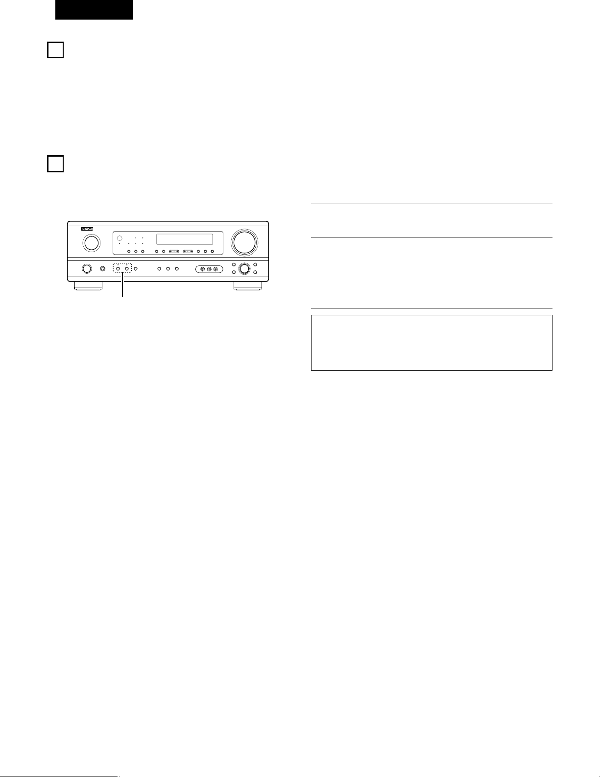
92
FRANCAIS
16
MEMOIRE DE DERNIERE FONCTION
• Cet appareil est équipé d’une mémoire de dernière fonction qui stocke les conditions des réglages d’entrée et de sortie telles qu’elles étaient
immédiatement après la mise hors tension.
• L’appareil est également équipé d’une mémoire de sauvegarde. Cette fonction fournit approximativement une semaine de stockage de
mémoire lorsque l’unité principale est mise hors tension et avec le cordon d’alimentation débranché.
17
INITIALISATION DU MICROPROCESSEUR
Lorsque l’indication de l’affichage est anormale ou quand l’utilisation de l’appareil ne donne pas les résultats escomptés, le microprocesseur doit
être initialisé en suivant la procédure suivante.
1
Eteindre l’appareil et retirer le cordon CA de la prise murale.
2
Maintenir le touche SPEAKER A suivant et le touche
SPEAKER B, et brancher le cordon CA dans la prise.
3
Vérifier que l’affichage clignote dans son intégralité à un
intervalle de 1 seconde environ, relâcher les doigts des 2
touches, et le microprocesseur sera initialisé.
REMARQUES:
•
Si l’étape 3 ne fonctionne pas, recommencer à partir de l’étape 1
.
• Si le micro-ordinateur a été réinitialisé, tous les réglages de
touche sont réinitialisés aux valeurs par défaut (les valeurs
réglées à la livraison de l’usine).
2
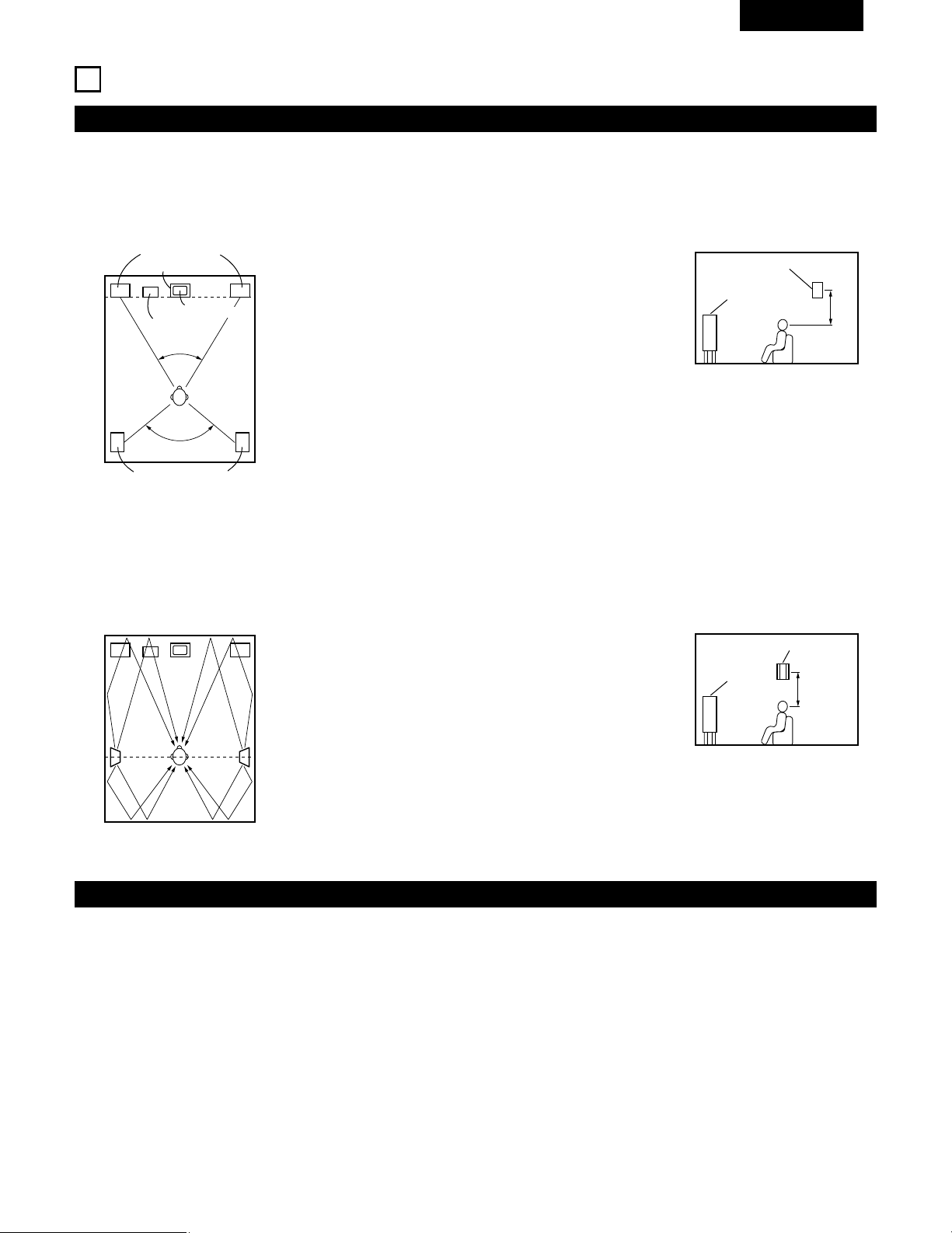
93
FRANCAIS
18
INFORMATIONS SUPPLEMENTAIRES
• Placer les enceintes avant, l’enceinte centrale et le subwoofer
aux mêmes positions que dans l’exemple (1).
• Placer les enceintes d’ambiance directement au niveau des
côtés de la position d’écoute et de 60 à 90 cm (2 à 3 pieds) au-
dessus du niveau des oreilles.
• Les signaux des canaux d’ambiance se réfléchissent sur les
murs de la manière indiquée sur le diagramme de gauche,
créant une impression d’expansion.
Les signaux des canaux d’ambiance se réfléchissent sur les
murs de la manière indiquée sur le diagramme de gauche,
créant une présentation des sons d’ambiance enveloppante et
réaliste.
• Placer les enceintes avant avec leurs surfaces avant autant que
possible en regard de l’écran de téléviseur ou de moniteur.
Placer l’enceinte centrale entre les enceintes avant gauche et
droite et pas plus loin de la position d’écoute que les enceintes
avant.
• Consulter le mode d’emploi de votre subwoofer pour un conseil
sur son placement dans la pièce d’écoute.
• Si les enceintes d’ambiance sont à rayonnement direct
(monopolaire), les placer légèrement derrière et à un angle par
rapport à la position d’écoute et parallèlement aux murs, de 60
à 90 cm (2 à 3 pieds) au-dessus du niveau des oreilles à la
principale position d’écoute.
Exemples de réglage d’enceintes
Nous décrivons ici un nombre de réglages d’enceintes pour différents buts. Utiliser ces exemples pour installer votre système en fonction du type
d’enceintes utilisées et du principal objectif d’utilisation.
(1) Réglage de base
Utiliser ce réglage si votre principal objectif est d’écouter la musique de film et en cas d’utilisation d’un ensemble (deux enceintes) de haut-
parleurs une ou deux voies normaux tels que les enceintes d’ambiance.
(2) Utilisant des enceintes types diffusion pour les enceintes d’ambiance
Pour l’impression d’enveloppement des sons d’ambiance la plus forte, des enceintes à radiation diffuse telles que les types bipolaires ou
dipolaires (THX), assurent une dispersion plus large que celle qu’il est possible d’obtenir d’une enceinte à rayonnement direct (monopolaire).
Placer ces enceintes à l’un des côtés de la principale position d’écoute, montées au-dessus du niveau des oreilles.
Subwoofer
Enceinte d’ambiance
Enceinte avant
60 à 90 cm
(2 à 3 pieds)
Enceinte d’ambiance
Enceinte avant
Enceintes d’ambiance
120°
Enceintes avant
45°
Enceinte centrale
Moniteur
Comme vu de dessus
Comme vu de dessus
Comme vu de côté
Comme vu de côté
Trajet du son d’ambiance en
provenance des enceintes vers la
position d’écoute
Ambiance
Cet appareil est équipé d’un circuit de traitement du signal numérique, qui permet de lire des sources de programme en mode d’ambiance pour
obtenir la même sensation de présence comme dans une salle de cinéma.
Dolby Surround
(1) Dolby Digital
Dolby Digital est le format de signaux numériques de canaux multiples développé par Dolby Laboratories.
Dolby Digital comprend jusqu’à “5.1” canaux – avant gauche, avant droit, central, gauche d’ambiance, droit d’ambiance, et un canal
supplémentaire exclusivement réservé pour les effets supplémentaires des sons de graves profondes (le canal LFE – effet de basse
fréquence, également appelé le canal “.1”, contenant de basses fréquences jusqu’à 120 Hz).
Contrairement au format analogique Dolby Pro Logic, les principaux canaux de Dolby Digital peuvent tous contenir des informations sonores
pleine gamme, des graves les plus basses jusqu’aux fréquences les plus élevées – 22 kHz. Les signaux de chaque canal sont distincts des
autres, permettant de repérer l’imagerie sonore, et Dolby Digital offre une formidable gamme dynamique, des effets sonores les plus
puissants aux sons les plus doux, les plus calmes, sans bruit ni distorsion.
60 à 90 cm
(2 à 3 pieds)
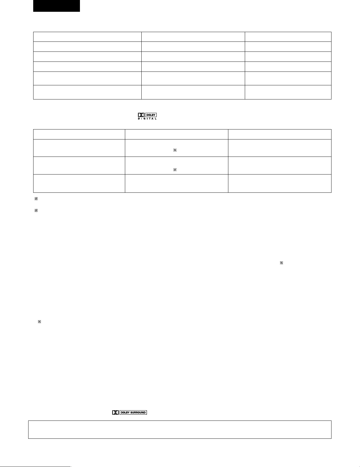
94
FRANCAIS
2 Dolby Digital et Dolby Pro Logic
Comparaison de systèmes d’ambiance domestiques
Nbre. de canaux enregistrés (éléments)
Nbre. de canaux de lecture
Canaux de lecture (max.)
Traitement audio
Limite de reproduction haute fréquence de canal
d’ambiance
Dolby Digital
5.1 ch
5.1 ch
L, R, C, SL, SR, SW
Traitement numérique discret
Encodage/décodage Dolby Digital
20 kHz
Dolby Pro Logic
2 ch
4 ch
L, R, C, S (SW - recommandé)
Traitement à matrice analogique Dolby
Surround
7 kHz
2 Méthodes de lecture et média compatibles Dolby Digital
Marques indiquant la compatibilité Dolby Digital: .
Voici quelques exemples généraux. Se reporter également aux instructions d’utilisation du lecteur.
Média
LD (VDP)
DVD
Autres
(émissions par satellite, CATV, etc.)
Prises de sortie Dolby Digital
Prise de sortie RF coaxiale Dolby Digital
1
Sortie numérique optique ou coaxiale
(comme pour PCM)
2
Sortie numérique optique ou coaxiale
(comme pour PCM)
Méthodes de lecture (page de référence)
Régler le mode d’entrée à “AUTO”.
(Page 74)
Régler le mode d’entrée à “AUTO”.
(Page 74)
Régler le mode d’entrée à “AUTO”.
(Page 74)
1 Utiliser un adaptateur disponible dans le commerce pour raccorder le jack de sortie Dolby Digital du lecteur LD au jack d’entrée numérique.
Lors du raccordement, consulter la notice fournie avec l’adaptateur.
2 Certaines sorties numériques DVD ont la fonction de commuter la méthode de sortie de signaux Dolby Digital entre “courant binaire” et
“(convertir à) PCM”. Lors de la lecture en mode Dolby Digital sur cet appareil, commuter le mode de sortie du lecteur DVD sur “bit
stream“ dans certains cas les lecteurs sont équipés des deux sorties numériques “bit stream + PCM“ et “PCM only“. Dans ce cas
connecter les prises “bit stream + PCM“ à cet appareil.
(2) Dolby Pro Logic II
• Dolby Pro Logic II est un nouveau format de lecture multi-canaux développé par les Laboratoires Dolby utilisant la technologie de commande
par rétroaction logique et offrant des nombreuses améliorations par rapport aux circuits conventionnels Dolby Pro Logic.
• Dolby Pro Logic II peut être utilisé pour décoder non seulement des sources enregistrées en Dolby Surround ( ), mais également des
sources stéréo normales en cinq canaux (avant gauche, avant droit, central, surround gauche et surround droit) pour parvenir à un son
d'environnement surround.
• Alors que pour un système Dolby Pro Logic conventionnel, la bande de fréquences du canal d'environnement surround était réduite, le
Dolby Pro Logic II apporte une gamme de fréquences plus large (20 Hz à 20 kHz ou plus). De plus, alors que les canaux surround étaient
monoauraux (les canaux surround gauche et droit étant les mêmes) dans les anciens systèmes Dolby Pro Logic, ils sont reproduits comme
signaux stéréo par le système Dolby Pro Logic II.
• Il est possible de régler de nombreux paramètres selon le type de source et de contenu, de façon à parvenir à un décodage optimal (voir
page 80).
Sources enregistrées en Dolby Surround
Ce sont des sources pour lesquelles trois ou quatre canaux surround ont été enregistrées comme deux canaux en utilisant la technologie
de codage Dolby Surround.
Le Dolby Surround est utilisé pour les bandes sonores de films enregistrés sur DVDs, LDs et cassettes vidéo pouvant être reproduites sur
des magnétoscopes stéréo, de même que pour les émissions de radio en stéréo FM, de télévision, de transmission par satellite et de
télévision par câble.
Le décodage de ces signaux par la technologie Dolby Pro Logic rend la reproduction de son d'environnement multi-canaux possible. Ces
signaux peuvent également être reproduits sur un dispositif stéréo ordinaire; néanmoins, dans ce cas, le son sera de type stéréo normal.
Il y a deux types de signaux d'enregistrement de son d'environnement DVD Dolby.
q Les signaux PCM stéréo à 2 canaux
w Les signaux Dolby Digital à 2 canaux
Lorsqu'un de ces signaux est entré dans le AVR-1404/484, le mode d'environnement sonore est automatiquement réglé sur Dolby Pro
Logic II lorsque le mode "DOLBY/DTS SURROUND" est sélectionné.
2 Les sources enregistrées en Dolby Surround sont désignées par le logo indiqué ci-dessous.
Signe du support Dolby Surround:
Fabriqué sous licence des Dolby Laboratories.
“Dolby”, “Pro Logic” et le symbole D double sont les marques de fabrique enregistrées des Dolby Laboratories.
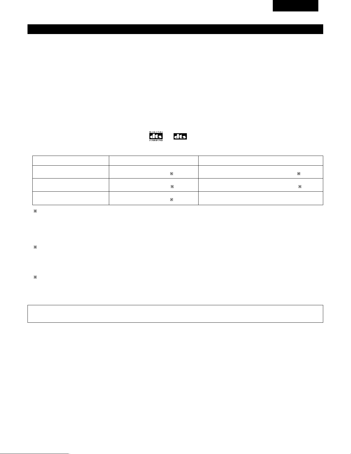
95
FRANCAIS
DTS Digital Surround
Digital Theater Surround (également appelé simplement DTS) est un format de signaux numériques de canaux multiples développé par Digital
Theater Systems.
DTS offre les mêmes canaux de lecture “5.1” que Dolby Digital (avant gauche, avant droit et central, gauche et droit d’ambiance) ainsi que le
mode stéréo deux canaux. Les signaux des différents canaux sont entièrement indépendants, éliminant le risque de détérioration de qualité
sonore à cause d’interférences entre signaux, diaphonie, etc.
DTS se caractérise par un débit binaire relativement plus élevé comparé à Dolby Digital (1234 kbps pour CD et LD, 1536 kbps pour DVD), donc il
fonctionne avec un taux de compression relativement bas. Pour cette raison, la quantité de données est grande, et lorsque la lecture DTS est
utilisée dans les salles de cinéma, un CD-ROM séparé synchronisé sur le film est joué.
Avec les LD et les DVD, il n’y a, bien sûr, pas besoin d’un disque supplémentaire; les images et le son peuvent être simultanément enregistrés
sur le même disque, donc les disques peuvent être manipulés de la même manière que des disques d’autres formats.
Ce sont également des CD enregistrés en DTS. Ces CD comprennent les signaux d’ambiance 5.1 canaux (comparés aux deux canaux sur les CD
actuels). Elles ne comprennent pas les données image, mais offrent une lecture d’ambiance sur des lecteurs de CD équipés de sorties numériques
(sortie numérique type PCM nécessaire).
La lecture de pistes DTS surround offre le même grand son compliqué que dans une salle de cinéma, simplement dans votre propre salon.
2 Méthodes de lecture et média compatibles DTS
Marques indiquant la compatibilité Dolby Digital DTS: et .
Voici quelques exemples généraux. Se reporter également aux instructions d’utilisation du lecteur.
Média
CD
LD (VDP)
DVD
Prises de sortie Dolby Digital
Sortie numérique optique ou coaxiale
(comme pour PCM) 2
Sortie numérique optique ou coaxiale
(comme pour PCM) 2
Sortie numérique optique ou coaxiale
(comme pour PCM) 3
Méthode de lecture (page de référence)
Régler le mode d’entrée à “AUTO” ou “DTS”. (Page 74).
Ne jamais régler le mode à “ANALOG” ou “PCM” 1
Régler le mode d’entrée à “AUTO” ou “DTS”. (Page 74).
Ne jamais régler le mode à “ANALOG” ou “PCM”. 1
Régler le mode d’entrée à “AUTO” ou “DTS”. (Page 74).
1 Les signaux DTS sont enregistrés de la même manière sur les CD et les LD que les signaux PCM. Pour cette raison, les signaux DTS non
décodés sont sortis comme parasites “sifflants” par les sorties analogiques du lecteur de CD ou de LD. Si ce parasite est reproduit avec
l’amplificateur réglé à un volume très élevé, il peut éventuellement endommager les enceintes. Pour éviter ceci, toujours changer le mode
d’entrée à “AUTO” ou “DTS” avant de reproduire des CD ou des LD enregistrés en DTS. De même, ne jamais changer le mode d’entrée
à “ANALOG” ou “PCM” pendant la lecture. Ceci s’applique également en cas de reproduction de CD ou de LD sur un lecteur de DVD ou
de LD/DVD compatible. Pour les DVD, les signaux DTS sont enregistrés d’une manière spéciale, donc ce problème ne se pose pas.
2 Les signaux fournis aux sorties numériques d’un lecteur de CD ou de LD peuvent subir un certain type de traitement de signal interne
(réglage de niveau de sortie, conversion de fréquence d’échantillonnage, etc.). Si cela se produit les signaux codés DTS peuvent être
traités de façon erronée, et ne peuvent pas être décodes par cet appareil ou risquent générer uniquement du bruit. Avant de lire de signaux
DTS pour la première fois, tourner la commande de volume global au minimum, commencer la lecture du disque DTS, ensuite vérifier si
l’indicateur DTS de cet appareil (voir page 82) s’allume avant d’augmenter le volume global.
3 Un lecteur de DVD avec sortie numérique compatible DTS est nécessaire pour reproduire des DVD DTS. Un logo de sortie numérique DTS
est reproduit sur le panneau avant des lecteurs de DVD compatibles.
Les récents modèles de lecteurs de DVD DENON comprennent une sortie numérique compatible DTS - consulter le mode d’emploi du
lecteur pour les informations sur la configuration de la sortie numérique pour la lecture DTS de DVD encodés en DTS.
“DTS” et “DTS Digital Surround” sont des marques déposées de Digital Theater Systems, Inc.
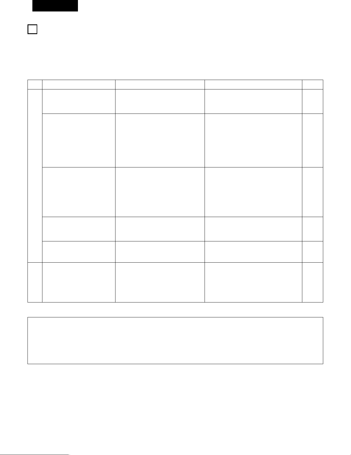
96
FRANCAIS
19
DEPISTAGE DES PANNES
Si un problème se produit, vérifier d’abord les points suivants:
1. Les connexions sont-elles correctes ?
2. L’ampli-tuner a-t-il été utilisé conformément au mode d’emploi ?
3. Les enceintes et les autres appareils fonctionnent-ils correctement ?
Si cet appareil ne fonctionne pas correctement, vérifier les points énumérés dans le tableau ci-dessous. Si le problème persiste, il peut y avoir un
mauvais fonctionnement. Débrancher immédiatement le cordon d’alimentation et contacter le revendeur.
Symptôme Cause Remèdes Page
Affichage pas allumé et aucun son
n’est produit lorsque l’appareil est
allumé.
• Le cordon d’alimentation n’est pas bien
branché.
• Vérifier l’insertion de la fiche du cordon
d’alimentation.
• Eteindre avec la télécommande après avoir
allumé l’interrupteur principal POWER.
56
73
Affichage allumé mais aucun son
n‘est produit.
• Les cordons des enceintes ne sont pas
correctement branchés.
• Mauvaise position de la touche de fonction
audio.
• Commande de volume réglée au minimum.
• La sourdine (MUTING) est activée.
• Signaux numériques pas entrés lorsque
l’entrée numérique est sélectionnée.
• Brancher correctement.
• Régler sur une position appropriée.
• Augmenter le volume jusqu’à un niveau
approprié.
• Désenclencher la sourdine (MUTING).
• Entrer des signaux numériques ou sélectionner
des prises d’entrée auxquelles sont entrés les
signaux numériques.
60, 61
74
75
76
74
Affichage n’est pas affiché et la LED
“ON/STANDBY” clignote de façon
rapide.
• Les bornes d’enceinte sont court-circuitées.
• Les trous de ventilation de l’appareil sont
obstrués.
• L’appareil fonctionne en continu à haute
puissance et/ou la ventilation n’est pas
appropriée.
• Mettre l’appareil hors tension, connecter
correctement les enceintes, puis le remettre
sous tension.
• Eteindre l’appareil, puis bien l’aérer pour le
refroidir.
Dès que l’appareil est refroidi, le rallumer.
• Eteindre l’appareil, puis bien l’aérer pour le
refroidir.
Dès que l’appareil est refroidi, le rallumer.
60, 61
52, 61
52, 61
Le son n’est produit que par un
canal.
• Connexion incomplète des cordons
d’enceinte.
• Connexion incomplète des cordons
d’entrée/sortie.
• Bien connecter.
• Bien connecter.
60, 61
56 ~ 61
Les positions des instruments sont
inversées pendant la lecture en
stéréo.
• Inverser les connexions des enceintes
gauche et droite ou des cordons
d’entrée/sortie gauche et droite.
• Vérifier les connexions gauche et droite.
60, 61
Cet appareil ne fonctionne pas
correctement lorsque la
télécommande est utilisée.
• Les piles sont usées.
• Télécommande trop loin de cet appareil.
• Obstacle entre cet appareil et la
télécommande.
• Une touche différente est enfoncée.
• Les pôles < et > de la pile sont insérés à
l’envers.
• Remplacer les piles par des piles neuves.
• Rapprocher.
• Retirer l’obstacle.
• Appuyer sur la touche appropriée.
• Insérer correctement les piles.
62
62
62
—
62
Problèmes communs se présentant lors de l’écoute de disques
compacts, disques, cassettes et d’émissions FM, etc.
Télécommande.
Remarque:
Lorsqu’un subwoofer a été connecté et que la fonction d’ambiance virtuelle est utilisée, le signal lu à partir du canal du subwoofer est de type
LFE uniquement. (uniquement lors de la lecture de signaux Dolby Digital ou DTS) pour les réglages initiaux effectués en usine (ex ; le réglage
de l’enceinte frontale est sur “LARGE” et le réglage du mode subwoofer est sur “NORM”).
Lorsque les effets de subwoofer doivent être faibles, en mode de configuration système, essayer de régler le mode subwoofer sur “+MAIN”
ou régler l’enceinte frontale sur “SMALL” dans les réglages de configuration système configuration d’enceinte.
Le fait d’effectuer ces réglages enclenche la lecture des sons de basse fréquence à partir du subwoofer.

97
FRANCAIS
20
SPECIFICATIONS
2 Section audio
• Amplificateur de puissance
Puissance de sortie nominale: Avant: 75 W + 75 W (8 Ω/ohms, 20 Hz ~ 20 kHz avec D.H.T. de 0,08%)
110 W + 110 W (6 Ω/ohms. 1 kHz avec D.H.T. de 0,7%)
Central: 75 W (8 Ω/ohms, 20 Hz ~ 20 kHz avec D.H.T. de 0,08%)
110 W (6 Ω/ohms. 1 kHz avec D.H.T. de 0,7%)
Ambiance: 75 W + 75 W (8 Ω/ohms, 20 Hz ~ 20 kHz avec D.H.T. de 0,08%)
110 W +110 W (6 Ω/ohms. 1 kHz avec D.H.T. de 0,7%)
Bornes de sortie: Avant: A ou B 16 à 16 Ω/ohms
A + B 12 à 16 Ω/ohms
Central/Ambiance: 16 à 16 Ω/ohms
• Analogique (Analog)
Sensibilité d’entrée/Impédance d’entrée: 200 mV / 47 kΩ/kohms
Réponse en fréquence: 10 Hz ~ 100 kHz: +1, –3 dB (TONE DEFEAT ON)
Rapport signal/bruit: 98 dB (IHF-A chargée) (TONE DEFEAT ON)
2 Section vidéo
• Prises vidéo standard
Niveau/impédance d’entrée et de sortie: 1 Vc-c, 75 Ω/ohms
Réponse en fréquence: 5 Hz ~ 10 MHz — +1, –3 dB
• Prises de sortie S-vidéo
Niveau/impédance d’entrée et de sortie: Signal Y — 1 Vc-c, 75 Ω/ohms
Signal C — 0,286 Vc-c, 75 Ω/ohms
Réponse en fréquence: 5 Hz ~ 10 MHz — +1, –3 dB
2 Section tuner
[FM] (Remarque: µV à 75 Ω/ohms, 0 dBf = 1 x 10
–
15
W) [AM]
Gamme de réception: 87.50 MHz ~ 107.90 MHz 520 kHz ~ 1710 kHz
Sensibilité utile: 1.0 µV (11.2 dBf) 18 µV
Seuil de sensibilité 50 dB: MONO 1.6 µV (15.3 dBf)
STEREO 23 µV (38.5 dBf)
Rapport signal/bruit: MONO 80 dB (IHF-A chargée)
STEREO 75 dB (IHF-A chargée)
Distorsion harmonique totale MONO 0.15% (1kHz)
STEREO 0.3% (1kHz)
2 Généralités
Alimentation: CA 120 V, 60 Hz
Consommation: 3,8 A
Dimensions externes maximales: 434 (L) x 147 (H) x 417 (P) mm
Poids: 10,3 kg
2 Télécommande (RC-942)
Piles: Type R6P/AA (deux piles)
Dimensions externes: 55 (L) x 225 (H) x 34.5 (P) mm
Poids: 165 g (avec les piles)
* Aux fins d’amélioration, les spécifications et la conception sont sujettes à modification sans préavis.

98
LIST OF PRESET CODES / LISTE DE CODES PRÉRÉGLÉS
DVD
Denon 014, *[111]
Aiwa 009
Hitachi 010
JVC 006, 011
Konka 012, 013
Magnavox 005
Mitsubishi 004
Panasonic 014
Philips 005, 015, 016, 017
Pioneer 003, 008
Sanyo 018
Sony 002, 019, 020
Toshiba 001, 021, 022
Zenith 023
VDP
Denon 028, 029, 112
Magnavox 026
Mitsubishi 028
Panasonic 029, 030
Philips 026
Pioneer 028, 031
RCA 032
Sony 033, 034, 035, 036
VCR
Admiral 081
Aiko 095
Aiwa 009
Akai 026, 027, 070, 072, 082, 083, 084
Alba 055
Amstrad 009
ASA 042
Asha 087
Audio Dynamic 005, 085
Audiovox 088
Beaumark 087
Broksonic 086, 093
Calix 088
Candle 006, 087, 088, 089, 090
Canon 049, 057
Capehart 025, 055, 056, 071
Carver 015
CCE 095
Citizen 006, 007, 087, 088, 089, 090, 095
Craig 007, 087, 088, 091, 115
Curtis Mathes 006, 049, 073, 080, 087, 090, 092
Cybernex 087
Daewoo 025, 055, 059, 074, 089, 093, 095,
096
Daytron 025, 055
DBX 005, 085
Dumont 053
Dynatech 009
Electrohome 001, 088, 097
Electrophonic 088
Emerson 001, 009, 017, 027, 086, 088, 089,
092, 093, 097, 100, 101, 102, 103,
104, 117
Fisher 009, 028, 031, 053, 054, 091, 099,
115
GE 007, 011, 049, 050, 051, 052, 073,
080, 087
Go Video 047, 048
Goldstar 000, 006, 012, 062, 088
Gradiente 094
Grundig 042
Harley Davidson 094
Harman Kardon 040, 062
Hi-Q 091
Hitachi 009, 013, 023, 026, 058, *[108],
109, 110, 111
JC Penny 004, 005, 007, 023, 028, 049, 062,
085, 087, 088
Jensen 013, 026
JVC 004, 005, 006, 026, 029, 043, 044,
045, 046, 085
Kenwood 004, 005, 006, 026, 029, 033, 045,
085, 090
Kodak 088
Lloyd 009, 094
LXI 088
Magnavox 015, 016, 042, 049, 063, 106
Magnin 087
Marantz 004, 005, 006, 015, 042, 049, 085,
090
Marta 088
MEI 049
Memorex 009, 033, 049, 053, 060, 081, 087,
088, 091, 094, 115
Metz 123, 124, 125, 126, 127, 128
MGA 001, 017, 027, 041, 097
MGN Technology 087
Midland 011
ENGLISH FRANCAIS

99
Minolta 013, 023
Mitsubishi 001, 003, 008, 013, 014, 017, 027,
029, 039, 040, 041, 045, 097
Motorola 081
Montgomery Ward
001, 002, 007, 009, 049, 063, 081,
115, 117
MTC 009, 087, 094
Multitech 007, 009, 011, 087, 090, 094
NAD 038
NEC 004, 005, 006, 018, 026, 029, 045,
061, 062, 085
Nikko 088
Noblex 087
Optimus 081, 088
Optonica 021
Panasonic 024, 049, 064, 066, 067, 068, 069,
107
Perdio 009
Pentax 009, 013, 023, 058, 090
Philco 015, 016, 049
Philips 015, 021, 042, 049, 105
Pilot 088
Pioneer 005, 013, 029, 036, 037, 038, 045,
085
Portland 025, 055, 090
Proscan 063, 080
Pulsar 060
Quartz 033
Quasar 034, 035, 049
Radio Shack 001, 002, 021, 081, 087, 088, 091,
094, 097, 098, 115
Radix 088
Randex 088
RCA 007, 013, 019, 023, 058, 063, 064,
065, 073, 080, 082, 087
Realistic 009, 021, 031, 033, 049, 053, 081,
087, 088, 091, 094, 097, 098
Ricoh 055
Salora 033, 041
Samsung 007, 011, 051, 059, 070, 083, 087,
089, 113
Sanky 081
Sansui 005, 026, 029, 045, 061, 085, 114
Sanyo 032, 033, 053, 087, 091, 115, 116
SBR 042
Scott 017, 020, 086, 089, 093, 117
Sears 013, 023, 028, 031, 033, 053, 054,
088, 091, 098, 099, 115
Sentra 055
Sharp 001, 002, 021, 097
Shogun 087
Sony 075, 076, 077, 078, 079, 121, 122
STS 023
Sylvania 009, 015, 016, 017, 041, 049, 094
Symphonic 009, 094
Tandy 009
Tashiko 009, 088
Tatung 004, 026, 030
Teac 004, 009, 026, 094
Technics 024, 049
Teknika 009, 010, 022, 049, 088, 094
TMK 087, 092
Toshiba 013, 017, 020, 041, 059, 089, 098,
099, 117
Totevision 007, 087, 088
Unirech 087
Vecrtor Research 005, 062, 085, 089, 090
Victor 005, 045, 046, 085
Video Concepts 005, 027, 085, 089, 090
Videosonic 007, 087
Wards 013, 021, 023, 087, 088, 089, 091,
094, 097, 118, 119, 120
XR-1000 094
Yamaha 004, 005, 006, 026, 062, 085
Zenith 060, 078, 079
TV
Admiral 045, 121
Adventura 122
Aiko 054
Akai 016, 027, 046
Alleron 062
A-Mark 007
Amtron 061
Anam 006, 007, 036
Anam National 061, 147
AOC 003, 007, 033, 038, 039, 047, 048,
049, 133
Archer 007
Audiovox 007, 061
Bauer 155
Belcor 047
Bell & Howell 045, 118
Bradford 061
Brockwood 003, 047
Candle 003, 030, 031, 032, 038, 047, 049,
050, 122
Capehart 003
Celebrity 046
ENGLISHFRANCAIS

100
Circuit City 003
Citizen 029, 030, 031, 032, 034, 038, 047,
049, 050, 054, 061, 095, 122, 123
Concerto 031, 047, 049
Colortyme 003, 047, 049, 135
Contec 013, 051, 052, 061
Cony 051, 052, 061
Craig 004, 061
Crown 029
Curtis Mathes 029, 034, 038, 044, 047, 049, 053,
095, 118
Daewoo 027, 029, 039, 048, 049, 054, 055,
106, 107, 137
Daytron 003, 049
Dimensia 044
Dixi 007, 015, 027
Electroband 046
Electrohome 029, 056, 057, 058, 147
Elta 027
Emerson 029, 051, 059, 060, 061, 062, 118,
123, 124, 139, 148
Envision 038
Etron 027
Fisher 014, 021, 063, 064, 065, 118
Formenti 155
Fortress 012
Fujitsu 004, 062
Funai 004, 062
Futuretech 004
GE 020, 036, 037, 040, 044, 058, 066,
088, 119, 120, 125, 147
Goldstar 000, 015, 029, 031, 039, 048, 051,
056, 057, 067, 068, 069, 116
Grundy 062
Hitachi 029, 031, 051, 052, 070, 111, 112,
113, 124, *[134]
Hitachi Pay TV 151
Infinity 017, 071
Janeil 122
JBL 017, 071
JC Penny 020, 034, 039, 040, 041, 044, 048,
050, 058, 066, 069, 076, 088, 090,
095, 125, 136, 159
JCB 046
JVC 019, 051, 052, 072, 073, 091, 117,
126
Kawasho 018, 046
Kenwood 038, 056, 057
Kloss 010, 032
Kloss Novabeam 005, 122, 127, 131
KTV 074, 123
Loewe 071
Logik 144
Luxman 031
LXI 008, 014, 017, 024, 040, 044, 063,
071, 075, 076, 077, 118, 125
Magnavox 005, 010, 017, 030, 033, 038, 050,
056, 071, 078, 079, 085, 089, 108,
109, 110, 127, 131, 132, 145
Marantz 015, 017, 071, 080
Matsui 027
Memorex 014, 027, 045, 083, 118, 144
Metz 160, 161, 162, 163
MGA 001, 039, 048, 056, 057, 058, 065,
081, 083
Midland 125
Minutz 066
Mitsubishi 001, 016, 039, 048, 056, 057, 058,
065, 081, 082, 083, 105
Montgomery Ward
011, 020, 144, 145, 146
Motorola 121, 147
MTC 031, 034, 039, 048, 095
NAD 008, 075, 076, 128
National 002, 036, 061, 147
National Quenties
002
NEC 031, 038, 039, 048, 057, 084, 086,
135, 147
Nikko 054
NTC 054
Optimus 128
Optonica 011, 012, 093, 121
Orion 004, 139
Panasonic 002, 009, 017, 036, 037, 071, 141,
143, 147
Philco 005, 010, 030, 050, 051, 056, 079,
085, 127, 131, 132, 145, 147
Philips 005, 015, 017, 050, 051, 056, 078,
087, 088, 089, 131, 132, 147
Pioneer 124, 128, 142
Portland 054
Price Club 095
Proscan 040, 044, 125
Proton 035, 051, 092, 129
Pulsar 042
Quasar 036, 037, 074, 141
Radio Shack 011, 044, 063, 093, 118
RCA 040, 044, 125, 130, 137, 151, 152
Realistic 014, 063, 093, 118
Saisho 027
ENGLISH FRANCAIS

101
Samsung 003, 015, 034, 053, 055, 057, 094,
095, 136, 153
Sansui 139
Sanyo 013, 014, 021, 022, 063, 064, 081,
096
SBR 015
Schneider 015
Scott 062
Sears 008, 014, 021, 022, 023, 024, 025,
040, 052, 057, 062, 063, 064, 065,
073, 075, 076, 097, 098, 125, 159
Sharp 011, 012, 013, 026, 093, 099, 100,
104, 121
Siemens 013
Signature 045, 144
Simpson 050
Sony 043, 046, 138, 146, 150
Soundesign 030, 050, 062
Spectricon 007, 033
Squareview 004
Supre-Macy 032, 122
Supreme 046
Sylvania 005, 010, 017, 030, 078, 079, 085,
089, 101, 127, 131, 132, 145, 155
Symphonic 004, 148
Tandy 012, 121
Tatung 036, 124
Technics 037
Teknika 001, 030, 032, 034, 052, 054, 078,
083, 095, 144, 156, 157
Tera 035, 129
Toshiba 008, 014, 034, 063, 075, 076, 095,
097, 136, 158, 159
Universal 020, 066, 088
Victor 019, 073, 126
Video Concepts 016
Viking 032, 122
Wards 005, 045, 066, 078, 085, 088, 089,
093, 102, 103, 131, 132, 148
Zenith 042, 114, 115, 140, 144, 149
Zonda 007
CABLE
ABC 006, *[007], 008, 009
Archer 010, 011
Century 011
Citizen 011
Colour Voice 012, 013
Comtronic 014
Eastern 015
Garrard 011
Gemini 030, 033, 034
General Instrument
030, 031, 032
Hytex 006
Jasco 011
Jerrold 009, 016, 017, 026, 032
Magnavox 018
Movie Time 019
NSC 019
Oak 000, 006, 020
Panasonic 001, 005
Philips 011, 012, 013, 018, 021
Pioneer 002, 003, 022
RCA 029
Regency 015
Samsung 014, 023
Scientific Atlanta 004, 024, 025
Signal 014
SL Marx 014
Starcom 009
Stargate 014
Teleview 014
Tocom 007, 016
TV86 019
Unika 011
United Artists 006
Universal 010, 011
Viewstar 018, 019
Zenith 027, 028
DBS (SATELLITE)
Alphastar 054
Chaparral 035, 036
Dishnet 053
Drake 037, 038
Echostar Dish 062, 066
GE 048, 055, 056
General Instruments
039, 040, 041
Grundig 070, 071, 072, 073
Hitachi 058, 059
Hughes Network 063, 064, 065, 069
JVC 057
Kathrein 074, 075, 076, 083
Magnavox 060
Nokia 070, 080, 084, 085, 086
Philips 060
Primestar 051
Proscan 048, 055, 056
ENGLISHFRANCAIS
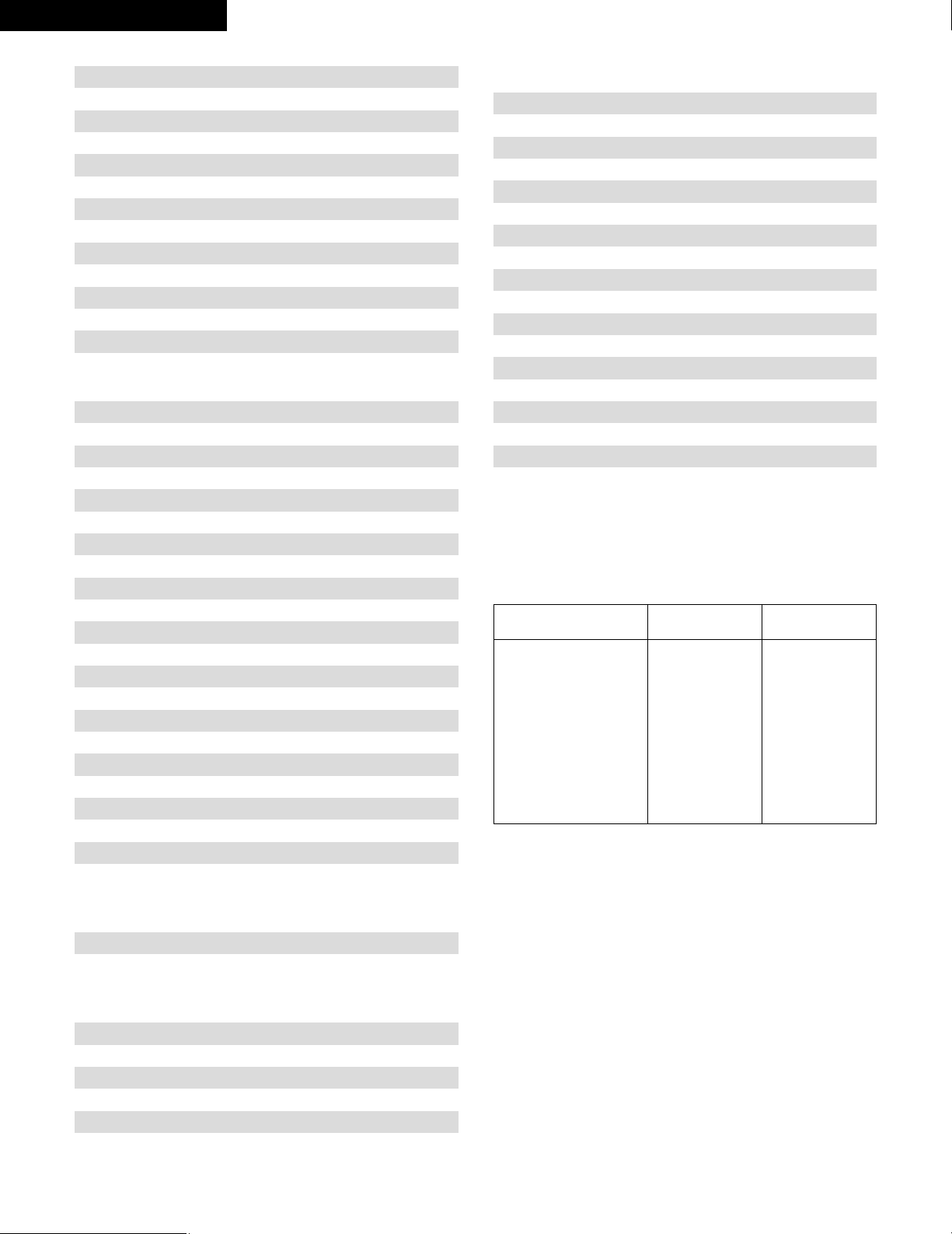
102
RCA 048, 055, 056, 068
Realistic 042
Sierra I 036
Sierra II 036
Sierra III 036
Sony 049, 067
STS1 043
STS2 044
STS3 045
SRS4 046
Technisat 077, 078, 079, 081, 082
Toshiba 047, 050
Uniden 061
CD
Denon *[111]
Aiwa 001, 035, 043
Burmster 002
Carver 003, 035
Emerson 004, 005, 006, 007
Fisher 003, 008, 009, 010
JVC 018, 019
Kenwood 011, 012, 013, 014, 017
Magnavox 006, 015, 035
Marantz 016, 028, 035
MCS 016, 024
Onkyo 025, 027
Optimus 017, 020, 021, 022, 023
Philips 014, 032, 033, 035
Pioneer 006, 022, 030
Sears 006
Sony 023, 031
Teac 002, 009, 028
Technics 016, 029, 036
Wards 035, 037
Yamaha 038, 039, 040, 041
Zenith 042
CDR
Denon *[111], 112
Philips 112
MD
Denon 113
Kenwood 003, 004
Onkyo 007
Sharp 005
Sony 006
TAPE
Denon *[111]
Aiwa 001, 002
Carver 002
Harman/Kardon 002, 003
JVC 004, 005
Kenwood 006
Magnavox 002
Marantz 002
Onkyo 016, 018
Optimus 007, 008
Panasonic 012
Philips 002
Pioneer 007, 008, 009
Sony 013, 014, 015
Technics 012
Victor 004
Wards 007
Yamaha 010, 011
*[ ] : Preset codes set upon shipment from the factory.
*[ ] : Les codes préréglés diffèrent en fonctiom des livraison de
l’usine.
ENGLISH FRANCAIS
DVD preset codes
Codes préréglés DVD
111 014
B
Model No.
Modéle numéro
DVD-700
DVD-900
DVD-910
DVD-1000
DVD-1200
DVD-1400
DVD-2800
DVD-2800II
DVD-2900
DVD-3800
DVM-1800
DVD-800
DVD-1600
DVD-2000
DVD-2500
DVD-3000
DVD-3300

103
MEMO:

Printed in China 511 4058 008
16-11, YUSHIMA 3-CHOME, BUNKYO-KU, TOKYO 113-0034, JAPAN
Telephone: (03) 3837-5321