DUCTED INDOOR UNITS
INSTALLATION MANUAL
High-Static Ducted Indoor Units
ARNU073BGA4
ARNU093BGA4
ARNU123BGA4
ARNU153BGA4
ARNU183BGA4
ARNU243BGA4
ARNU283BGA4
ARNU363BGA4
ARNU423BGA4
ARNU283BRA4
ARNU363BRA4
ARNU423BRA4
ARNU483BRA4
ARNU543BRA4
ARNU363B8A4
ARNU423B8A4
ARNU483B8A4
ARNU763B8A4
ARNU963B8A4
ARNU073BHA4
ARNU093BHA4
ARNU123BHA4
ARNU153BHA4
ARNU183BHA4
ARNU243BHA4
Built-In Ducted Indoor Units
ARNU073B3G4
ARNU093B3G4
ARNU123B3G4
ARNU153B3G4
ARNU183B4G4
ARNU243B4G4
Vertical Air Handler
Indoor Units
ARNU123NJA4
ARNU183NJA4
ARNU243NJA4
ARNU303NJA4
ARNU363NJA4
ARNU423NKA4
ARNU483NKA4
ARNU543NKA4
Low-Static Ducted Indoor Units
ARNU073L1G4
ARNU093L1G4
ARNU123L2G4
ARNU153L2G4
ARNU183L2G4
ARNU243L3G4

The instructions included in this manual must be followed to prevent prod-
uct malfunction, property damage, injury, or death to the user or other
people. Incorrect operation due to ignoring any instructions will cause
harm or damage. A summary of safety precautions begins on page 4.
Do not throw away, destroy, or lose this manual.
Please read carefully and store in a safe place for future reference.
Content familiarity required for proper installation.
For more technical materials such as submittals, engineering
databooks, and catalogs, visit www.lghvac.com.
For continual product development, LG Electronics U.S.A., Inc., reserves the right to change specifications without notice.
©LG Electronics U.S.A., Inc.
This document, as well as all reports, illustrations, data, information, and other materials are the property of LG Electronics U.S.A., Inc.
PROPRIETARY DATA NOTICE
This document, as well as all reports, illustrations, data, information, and other
materials are the property of LG Electronics U.S.A., Inc., and are
disclosed by LG Electronics U.S.A., Inc., only in confidence.
IM_MultiV_Ducted_IDU_5_16
3
Installation Manual
Due to our policy of continuous product innovation, some specifications may change without notification.
©LG Electronics U.S.A., Inc., Englewood Cliffs, NJ. All rights reserved. “LG” is a registered trademark of LG Corp.
TABLE OF CONTENTS
Safety Instructions .........................................................................4
Introduction .................................................................................... 9
Unit Nomenclature ....................................................................... 11
R410A Refrigerant ....................................................................... 12
General Data ...............................................................................13
Specications − High-Static BH Chassis ........................................... 13
Specications − High-Static BG Chassis ........................................... 14
Specications − High-Static BG Chassis ........................................... 15
Specications − High-Static BR/B8 Chassis...................................... 16
Specications − Low-Static B3/B4 Chassis ....................................... 18
Specications − Low-Static Ducted L1/L2/L3 Chassis ...................... 19
Specications − Vertical Air Handler NJ Chassis ............................... 20
Specications − Vertical Air Handler NK Chassis .............................. 21
Electrical − High-Static BH/BG/BR/B8 Chassis ................................. 22
Electrical − Low-Static Built-In B3/B4 Chassis .................................. 23
Electrical − Low-Static Ducted L1/L2/L3 Chassis .............................. 24
Dimensions – High-Static Ducted BH Chassis .................................. 25
Dimensions – High-Static Ducted BG Chassis .................................. 26
Dimensions – High-Static Ducted BR Chassis .................................. 27
Dimensions – High-Static Ducted B8 Chassis ................................... 28
Dimensions – Built-In Low-Static Ducted B3/B4 Chassis .................. 29
Dimensions – Low-Static Ducted L1/L2/L3 Chassis .......................... 30
Dimensions – Vertical Air Handler NJ Chassis .................................. 31
Dimensions – Vertical Air Handler NK Chassis.................................. 32
Refrigerant Piping Diagrams ............................................................. 33
General Installation Guidelines ....................................................34
Installation ...................................................................................35
Install Ducted IDU Chassis ................................................................ 35
Indoor Unit Dimensions ..................................................................... 36
Duct Connection Dimensions ............................................................ 37
Maintenance Clearances ................................................................... 38
Piping Connections ............................................................................ 39
Refrigerant Piping ........................................................................ 40
Condensate Piping ......................................................................44
Power and Control Wiring ............................................................46
Overview ............................................................................................ 46
Indoor Unit Communication Cable Connections ................................ 47
Indoor Unit Power Cable Connections .............................................. 50
DIP Switch Settings for Gen4 Equipment .......................................... 52
High-Static Ducted BH Chassis ......................................................... 53
High-Static Ducted BG Chassis ......................................................... 55
High-Static Ducted BR Chassis ......................................................... 57
High-Static Ducted B8 Chassis ......................................................... 59
Low-Static Ducted L1 Chassis ........................................................... 61
Low-Static Ducted L2/L3 Chassis ...................................................... 63
Low-Static Built-In B3/B4 Chassis ..................................................... 65
Vertical Air Handler NJ Chassis ......................................................... 67
Vertical Air Handler NK Chassis ........................................................ 69
Optional Wall-Mounted Sensor and Controller .................................. 71
Controls Setup ............................................................................. 72
Installation Checklist .................................................................... 76

4
Multi V Ducted Indoor Units
Due to our policy of continuous product innovation, some specifications may change without notification.
©LG Electronics U.S.A., Inc., Englewood Cliffs, NJ. All rights reserved. “LG” is a registered trademark of LG Corp.
SAFETY INSTRUCTIONS
The instructions below must be followed to prevent product malfunction, property damage, injury or death to the user or other people. Incor-
rect operation due to ignoring any instructions will cause harm or damage. The level of seriousness is classified by the symbols below.
WARNING
Do not install, remove, or re-install the unit by yourself
(end-user). Ask the dealer or an an LG trained service
provider to install the unit.
Improper installation by the user may result in water leakage, re,
explosion, electric shock, physical injury or death.
For replacement of an installed unit, always contact an
LG trained service provider.
There is risk of re, electric shock, explosion, and physical injury or death.
The outdoor unit is shipped with refrigerant and the service
valves closed. Do not open service valves on the unit until
all non-condensibles have been removed from the piping
system and authorization has been obtained from the com-
missioning agent.
There is a risk of physical injury or death.
Do not run the compressor with the service valves
closed.
There is risk of explosion, physical injury, or death.
Periodically check that the outdoor unit is not damaged.
There is risk of explosion, physical injury, or death.
Replace all control box and panel covers.
If cover panels are not installed securely, dust, water and animals may
enter the unit, causing re, electric shock, and physical injury or death.
Always check for system refrigerant leaks after the unit has
been installed or serviced.
Exposure to high concentration levels of refrigerant gas may lead to
illness or death.
Do not install the unit using defective hanging, attaching,
or mounting hardware.
There is risk of physical injury or death.
Wear protective gloves when handling equipment.
Sharp edges may cause personal injury.
Dispose of the packing materials safely.
• Packing materials, such as nails and other metal or wooden parts
may cause puncture wounds or other injuries.
• Tear apart and throw away plastic packaging bags so that children
may not play with them and risk suffocation and death.
Do not install the unit in any location exposed to open
ame or extreme heat. Do not touch the unit with wet hands.
There is risk of re, electric shock, explosion, and physical injury or death.
Install the unit considering the potential for earthquakes.
Improper installation may cause the unit to fall, resulting in physical
injury or death.
Do not change the settings of the protection devices.
If the pressure switch, thermal switch, or other protection device is
shorted and forced to operate improperly, or parts other than those
specied by LG are used, there is risk of re, electric shock, explosion,
and physical injury or death.
If the air conditioner is installed in a small space, take mea-
sures to prevent the refrigerant concentration from exceed-
ing safety limits in the event of a refrigerant leak.
Consult the latest edition of ASHRAE (American Society of Heating,
Refrigerating, and Air Conditioning Engineers) Standard 15. If the re-
frigerant leaks and safety limits are exceeded, it could result in personal
DANGER
This symbol indicates an imminently hazardous situation which, if not avoided, will result in death or
serious injury.
WARNING
This symbol indicates a potentially hazardous situation which, if not avoided, could result in death or
serious injury.
CAUTION
This symbol indicates a potentially hazardous situation which, if not avoided, may result in minor or
moderate injury.
Note:
This symbol Indicates situations that may result in equipment or property damage accidents only.
This symbol indicates an action that should not be performed.
TABLE OF SYMBOLS
INSTALLATION
DANGER
Don’t use or store ammable gas or combustibles near the unit.
There is risk of re, explosion, and physical injury or death.
5
Installation Manual
Due to our policy of continuous product innovation, some specifications may change without notification.
©LG Electronics U.S.A., Inc., Englewood Cliffs, NJ. All rights reserved. “LG” is a registered trademark of LG Corp.
SAFETY INSTRUCTIONS
injuries or death from oxygen depletion.
CAUTION
Be very careful when transporting the product.
• Do not attempt to carry the product without assistance.
• Some products use polypropylene bands for packaging. Do not use polypropylene bands to lift the unit.
• Suspend the unit from the base at specified positions.
• Support the unit at a minimum of four points to avoid slippage from rigging apparatus.
• Failure to follow these directions may result in minor or moderate physical injury.
INSTALLATION – CONTINUED
Note:
Properly insulate all cold surfaces to prevent “sweating.”
Cold surfaces such as uninsulated pipe can generate condensate that
may drip and cause a slippery oor condition and/or water damage to
walls.
When installing the unit in a hospital, mechanical room, or
similar electromagnetic eld (EMF) sensitive environment,
provide sufcient protection against electrical noise.
Inverter equipment, power generators, high-frequency medical equip-
ment, or radio communication equipment may cause the air conditioner to
operate improperly. The unit may also affect such equipment by creating
electrical noise that disturbs medical treatment or image broadcasting.
Do not use the product for special purposes such as pre-
serving foods, works of art, wine coolers, or other precision
air conditioning applications. This equipment is designed to
provide comfort cooling and heating.
There is risk of property damage.
Do not make refrigerant substitutions. Use R410A only.
If a different refrigerant is used, or air mixes with original refrigerant, the
unit will malfunction and become damaged.
Do not install the unit in a noise sensitive area.
When connecting refrigerant tubing, remember to allow for
pipe expansion.
Improper piping may cause refrigerant leaks and system malfunction.
Take appropriate actions at the end of HVAC equipment life
to recover, recycle, reclaim or destroy R410A refrigerant ac-
cording to applicable U.S. Environmental Protection Agency
(EPA) rules.
Periodically check that the outdoor unit is not damaged.
There is a risk of equipment damage.
Install the unit in a safe location where no one can step on or
fall onto it.
Do not install the unit with defective hanging,
attaching, or mounting hardware.
There is risk of unit and property damage.
Install the drain hose to ensure adequate drainage.
There is a risk of water leakage and property damage.
Don’t store or use ammable gas/combustibles near the
unit.
There is risk of product failure.
Always check for system refrigerant leaks after the unit has
been installed or serviced.
Low refrigerant levels may cause product failure
The unit is shipped with refrigerant and the service valves
closed.
Do not open service valves on the unit until all
non-condensibles have been removed from the piping sys-
tem and authorization to do so has been obtained from the
com-missioning agent.
There is a risk of refrigerant contamination, refrigerant loss and equip-
ment damage.
6
Multi V Ducted Indoor Units
Due to our policy of continuous product innovation, some specifications may change without notification.
©LG Electronics U.S.A., Inc., Englewood Cliffs, NJ. All rights reserved. “LG” is a registered trademark of LG Corp.
SAFETY INSTRUCTIONS
WIRING
DANGER
High voltage electricity is required to operate this system.
Adhere to the National Electrical Codes and these
instructions when wiring.
Improper connections and inadequate grounding can cause accidental
injury or death.
Always ground the unit following local, state, and National
Electrical Codes.
Turn the power off at the nearest disconnect before servicing
the equipment.
Electric shock can cause physical injury or death.
Properly size all circuit breakers or fuses.
There is risk of re, electric shock, explosion, physical injury or death.
WARNING
The information contained in this manual is intended for use
by an industry-qualied, experienced, trained electrician
familiar with the U.S. National Electric Code (NEC) who is
equipped with the proper tools and test instruments.
Failure to carefully read and follow all instructions in this manual can
result in equipment malfunction, property damage, personal injury or
death.
Ensure the unit is connected to a dedicated power source
that provides adequate power.
If the power source capacity is inadequate or the electric work is not per-
formed properly, it may result in re, electric shock, physical injury or death.
Refer to local, state, and federal codes, and use power wires
of sufcient current capacity and rating.
Wires that are too small may generate heat and cause a re.
Secure all eld wiring connections with appropriate wire
strain relief.
Improperly securing wires will create undue stress on equipment power
lugs. Inadequate connections may generate heat, cause a re and
physical injury or death.
Properly tighten all power connections.
Loose wiring may overheat at connection points, causing a re, physical
injury or death.
Note:
Do not cut, lengthen or shorten the communications and
power cable between any dry contact unit and its connected
indoor unit. Do not install the unit in a location where the com-
munications and power cable cannot be safely and easily con-
nected between the two units. Do not allow strain on this cable.
Poor cable connections can cause equipment malfunction.
7
Installation Manual
Due to our policy of continuous product innovation, some specifications may change without notification.
©LG Electronics U.S.A., Inc., Englewood Cliffs, NJ. All rights reserved. “LG” is a registered trademark of LG Corp.
OPERATION
DANGER
Do not provide power to or operate the unit if it is ooded
or submerged.
There is risk of re, electric shock, physical injury or death.
Use a dedicated power source for this product.
There is risk of re, electric shock, physical injury or death.
Do not operate the disconnect switch with wet hands.
There is risk of re, electric shock, physical injury or death.
Periodically verify the hanging bolts and other hardware
securing the unit have not deteriorated.
If the unit falls from its installed location, it can cause property damage,
product failure, physical injury or death.
If refrigerant gas leaks out, ventilate the area before operat-
ing the unit.
If the unit is mounted in an enclosed, low-lying, or poorly ventilated area
and the system develops a refrigerant leak, it may cause re, electric
shock, explosion, physical injury or death.
Note:
Clean up the site after installation is nished, and check
that no metal scraps, screws, or bits of wiring have been left
inside or surrounding the unit.
Do not use this equipment in mission critical or special-
purpose applications such as preserving foods, works of art,
wine coolers or refrigeration. This equipment is designed to
provide comfort cooling and heating.
Provide power to the compressor crankcase heaters at least
six (6) hours before operation begins.
Starting operation with a cold compressor sump(s) may result in severe
bearing damage to the compressor(s). Keep the power switch on during
the operational season.
Do not block the inlet or outlet.
Unit may malfunction.
Securely attach the electrical cover to the indoor unit. Non-
secured covers can result in re due to dust or water in the
service panel.
Periodically verify the equipment mounts have not deterio-
rated.
If the base collapses, the unit could fall and cause property damage or
product failure.
Do not allow water, dirt, or animals to enter the unit.
There is risk of unit failure.
WARNING
Do not allow water, dirt, or animals to enter the unit.
There is risk of unit failure, re, electric shock, physical injury or death.
Avoid excessive cooling and periodically perform ventilation
to the unit.
Inadequate ventilation is a health hazard.
Do not touch refrigerant piping during or after operation.
It can cause burns or frostbite.
Do not operate the unit with the panel(s) or protective
cover(s) removed; keep ngers and clothing away from
moving parts.
The rotating, hot, cold, and high-voltage parts of the unit can cause
physical injury or death.
Periodically check power cable and connection for damage.
Cable must be replaced by the manufacturer, its service agent, or similar
qualied persons in order to avoid physical injury and/or electric shock.
Securely attach the electrical cover to the unit.
Non-secured electrical covers can result in burns or electric shock due to
dust or water in the service panel.
Do not open the inlet grille of the unit during operation.
Do not operate the unit with the panels or guards removed.
Do not insert hands or other objects through the inlet or
outlet when the unit is powered. Do not touch the electro-
static lter, if the unit includes one. The unit contains sharp,
rotating, hot, and high voltage parts that can cause personal
injury and/or electric shock.
Ensure no power is connected to the unit other than as
directed in this manual. Remove power from the unit before
removing or servicing the unit.
There is risk of unit failure, re, electric shock, physical injury or death.
Do not open the inlet grille of the unit during operation.
Do not operate the unit with the panels or guards removed.
Do not insert hands or other objects through the inlet or out-
let with the unit is plugged in. Do not touch the electrostatic
lter, if the unit includes one.
The unit contains sharp, rotating, hot, and high voltage parts that can
cause personal injury and/or electric shock.
CAUTION
To avoid physical injury, use caution when cleaning or
servicing the air conditioner.

8
Multi V Ducted Indoor Units
Due to our policy of continuous product innovation, some specifications may change without notification.
©LG Electronics U.S.A., Inc., Englewood Cliffs, NJ. All rights reserved. “LG” is a registered trademark of LG Corp.
9
Installation Manual
Due to our policy of continuous product innovation, some specifications may change without notification.
©LG Electronics U.S.A., Inc., Englewood Cliffs, NJ. All rights reserved. “LG” is a registered trademark of LG Corp.
INTRODUCTION
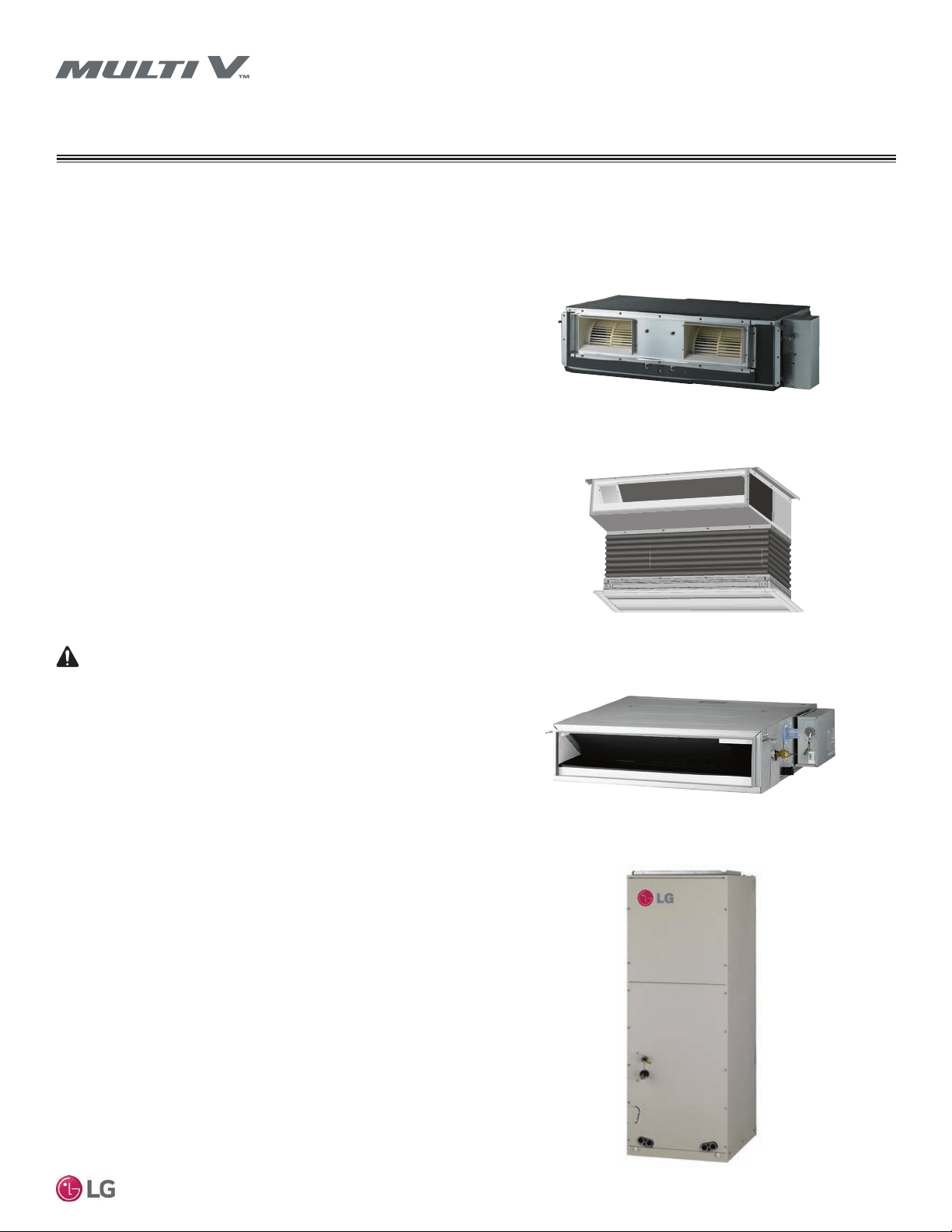
Ducted Indoor Units
This manual describes how to install LG ducted indoor units (IDU)
for Multi V Variable Refrigerant Flow (VRF) heat pump and heat
recovery systems. Table 1 lists the available models. Refer to LG’s
Multi V Indoor Unit Engineering Manual for complete detailed
engineering data and selection procedures.
Safety
Safety of personnel is the primary concern during all procedures.
Read and understand the safety summary at the front of this manual.
Read and understand this installation procedure before beginning
installation. Use the appropriate tools and accessories during instal-
lation. Plan your work and do not work alone, if possible. Know how
to obtain emergency medical and fire fighting assistance.
Installation Personnel
This equipment is intended for installation by personnel trained
in the required construction, mechanical, electrical, and/or other
disciplines.
Applicable Codes
Personnel must be familiar with and follow the applicable national,
state, and/or local codes.
• Pipes - vapor line and liquid line, with insulation
• 3/8” or 1/2” nuts, at washers, and lock/split washers
• 3/8” or 1/2” threaded hanger rods
• Insulated drain hose
• Additional drain hose
• Connecting cable (power and control)
• Level
• Screwdriver
• Electrical lineman pliers
• Electric drill
• Holesaw
• Drill
• Flaring tool set
• Tubing cutter
• Tube/pipe reamer
• Torque wrenches
• Allen wrench
• Gas-leak detector
• Thermometer
WARNING
Installation work must be performed by trained personnel and in ac-
cordance with national wiring standards and all local or other applicable
codes. Improper installation can result in re, electric shock, physical
injury, or death.
Note:
Please read all instructions before installing this product. Become familiar
with the unit, its components and connections, and the order of installa-
tion. Incorrect installation can degrade or prevent proper operation.
Figure 1: High-Static Ducted, BG/BR/B8/BH Chassis
Figure 2: Built-In Ducted, B3/B4 Chassis
Figure 3: Low-Static Ducted, L1/L2/L3 Chassis
Required Tools (field provided)
Required Parts (field provided)
Figure 4: Vertical Air Handler NJ/NK Chassis
10
Multi V Ducted Indoor Units
Due to our policy of continuous product innovation, some specifications may change without notification.
©LG Electronics U.S.A., Inc., Englewood Cliffs, NJ. All rights reserved. “LG” is a registered trademark of LG Corp.
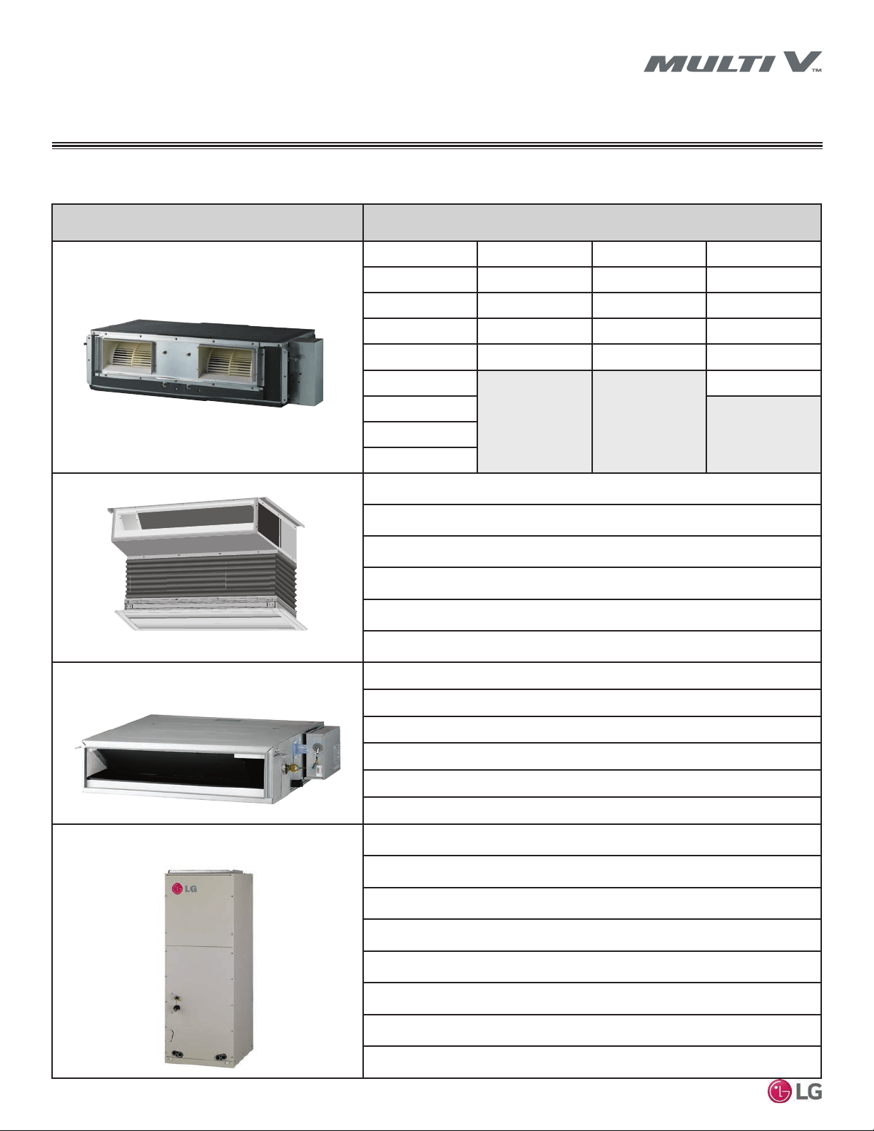
Unit Model Numbers
High-Static Ducted BG/BR/B8
ARNU073BGA4 ARNU283BRA4 ARNU363B8A4 ARNU073BHA4
ARNU093BGA4 ARNU363BRA4 ARNU423B8A4 ARNU093BHA4
ARNU123BGA4 ARNU423BRA4 ARNU483B8A4 ARNU123BHA4
ARNU153BGA4 ARNU483BRA4 ARNU763B8A4 ARNU153BHA4
ARNU183BGA4 ARNU543BRA4 ARNU963B8A4 ARNU183BHA4
ARNU243BGA4 ARNU243BHA4
ARNU283BGA4
ARNU363BGA4
ARNU423BGA4
Built-In Ducted B3/B4
(shown with optional canvas boot and grill)
ARNU073B3G4
ARNU093B3G4
ARNU123B3G4
ARNU153B3G4
ARNU183B4G4
ARNU243B4G4
Low-Static Ducted L1/L2/L3
ARNU073L1G4
ARNU093L1G4
ARNU123L2G4
ARNU153L2G4
ARNU183L2G4
ARNU243L3G4
Vertical Air Handler
ARNU123NJA4
ARNU183NJA4
ARNU243NJA4
ARNU303NJA4
ARNU633NJA4
ARNU423NKA4
ARNU483NKA4
ARNU543NKA4
Table 1: Multi V Ducted Indoor Units
INTRODUCTION
11
Installation Manual
Due to our policy of continuous product innovation, some specifications may change without notification.
©LG Electronics U.S.A., Inc., Englewood Cliffs, NJ. All rights reserved. “LG” is a registered trademark of LG Corp.
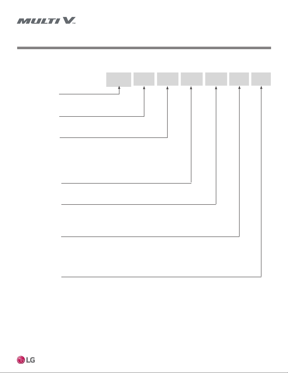
Cassette Indoor Units Nomenclature
ARN
U 07 3 BG A
Generation
4 = Fourth
BG = High-Static Ducted
BR = High-Static Ducted
B8 = High-Static Ducted
B3 = Built-In Ducted
B4 = Built-In Ducted
BH = Built-In Ducted
L1 = Low-Static Ducted
L2 = Low-Static Ducted
L3 = Low-Static Ducted
NJ = Vertical Air Handler
NK = Vertical Air Handler
Electrical Ratings
3 = 208–230V/60Hz/1Phase
Nominal Capacity
(Nominal cooling capacity in Btu/h)
Type
U = Inverter Heat Pump/Heat Recovery
Family
ARN = Multi V Indoor Unit (Refrigerant R410A)
4
Feature
C = Plasma Filter
A = No Plasma Filter
G = Low-Static
07 = 7,500
09 = 9,600
12 = 12,300
15 = 15,400
18 = 19,100
24 = 24,200
28 = 28,000
36 = 36,200
42 = 42,000
48 = 48,000
54 = 54,000
76 = 76,000
96 = 96,000
UNIT NOMENCLATURE
Chassis/Model Type
12
Multi V Ducted Indoor Units
Due to our policy of continuous product innovation, some specifications may change without notification.
©LG Electronics U.S.A., Inc., Englewood Cliffs, NJ. All rights reserved. “LG” is a registered trademark of LG Corp.
R410A REFRIGERANT
R410A refrigerant has a higher operating pressure in comparison to R22 refrigerant and, therefore, all piping system materials
installed must have a higher resisting pressure than the materials traditionally used in R22 systems.
R410A refrigerant is an azeotrope of R32 and R125, mixed at 50:50, so the ozone depletion potential (ODP) is 0.
WARNING
• Do not place the refrigerant cylinder in direct sunlight. Refrigerant cylinder may explode causing severe injury or death.
Note:
• Because R410A is a combination of R32 and R125, the required additional refrigerant must be charged in its liquid state. If the
refrigerant is charged in its gaseous state, its composition changes and the system will not work properly.
• Do not heat piping more than necessary during installation. Piping may become soft and fail when pressurized.
• Do not use any piping that has not been approved for use in high-pressure refrigerant systems. Piping wall thickness must comply
with the applicable local, state, and federal codes for the 551 psi design pressure of R410A. Inadequate piping may fail when
pressurized.
13
Installation Manual
Due to our policy of continuous product innovation, some specifications may change without notification.
©LG Electronics U.S.A., Inc., Englewood Cliffs, NJ. All rights reserved. “LG” is a registered trademark of LG Corp.
1
Power Input is rated at high speed.
2
Take appropriate actions at the end of HVAC equipment life to recover, recycle, reclaim or
destroy R410A refrigerant according to applicable regulations (40 CFR Part 82, Subpart F)
under section 608 of CAA.
3
All communication cable to be minimum 18 AWG, 2-conductor, stranded, shielded and
must comply with applicable local and national codes. Ensure the communication cable
is properly grounded at the master outdoor unit only. Do not ground the ODU−IDU com-
munications cable at any other point.
EEV: Electronic Expansion Valve
Power wiring is field supplied and must comply with the applicable local and national
codes. Power Supply (V/Hz/Ø): 208-230/60/1
This unit comes with a dry nitrogen charge.
This data is rated 0 ft above sea level, with 25 ft of refrigerant line per indoor unit and a 0 ft
level difference between outdoor and indoor units. All capacities are net with a combina-
tion ratio between 95-105%.
Cooling capacity rating obtained with air entering the indoor coil at 80ºF dry bulb (DB) and
67ºF wet bulb (WB) and outdoor ambient conditions of 95ºF dry bulb (DB).
Heating capacity rating obtained with air entering the indoor unit at 70ºF dry bulb (DB) and
outdoor ambient conditions of 47ºF dry bulb (DB) and 43ºF wet bulb (WB).
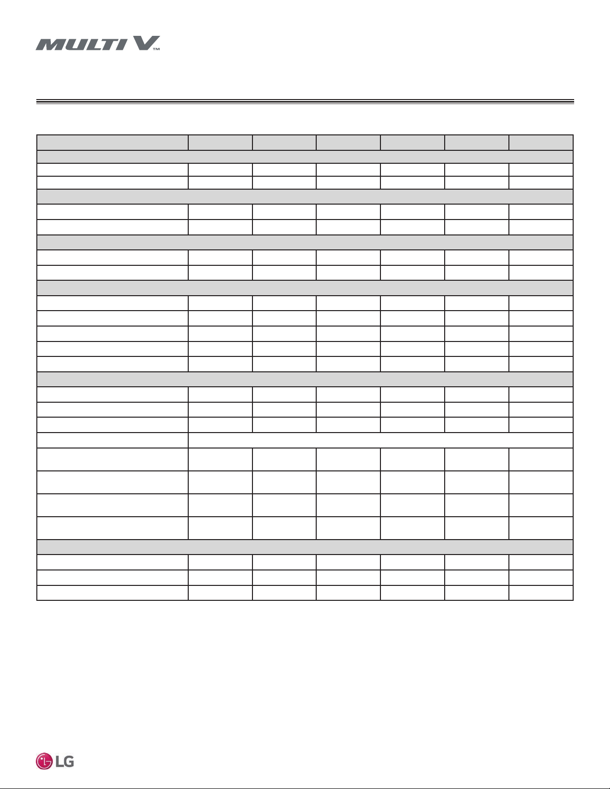
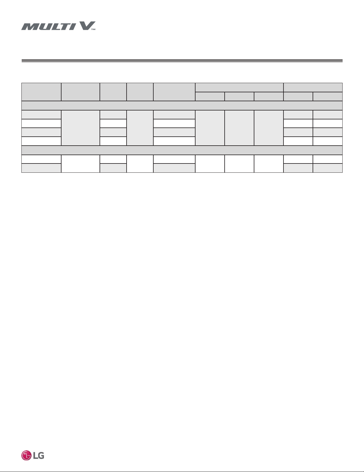
Table 2: High-Static Ducted BH Chassis IDU Specications
Model No.
ARNU073BHA4 ARNU093BHA4 ARNU123BHA4 ARNU153BHA4 ARNU183BHA4 ARNU243BHA4
Cooling Mode Performance
Capacity (Btu/h)
7,500 9,600 12,300 15,400 19,100 24,200
Power Input
1
(W)
150 150 150 150 150 150
Heating Mode Performance
Capacity (Btu/h)
8,500 10,900 13,600 17,100 21,500 27,300
Power Input
1
(W)
150 150 150 150 150 150
Entering Mixed Air
Cooling Max. (°F WB)
76 76 76 76 76 76
Heating Min. (°F DB)
59 59 59 59 59 59
Unit Data
Refrigerant Type
2
R410A R410A R410A R410A R410A R410A
Refrigerant Control
EEV EEV EEV EEV EEV EEV
Net Unit Weight (lbs.)
58.4 58.4 58.4 58.4 58.4 58.4
Shipping Weight (lbs.)
68.3 68.3 68.3 68.3 68.3 68.3
Communication Cable
4
(No. x AWG)
2 x 18 2 x 18 2 x 18 2 x 18 2 x 18 2 x 18
Fan
Type
Sirocco Sirocco Sirocco Sirocco Sirocco Sirocco
Motor
1 1 1 1 1 1
Housing
2 2 2 2 2 2
Motor/Drive
Brushless Digitally Controlled / Direct
Airflow Rate H/M/L (CFM)
Standard Mode
258 / 222 / 198 258 / 222 / 198 307 / 258 / 198 388 / 357 / 307 466 / 413 / 258 618 / 519 / 445
Airflow Rate H/M/L (CFM)
High Mode (Factory Set)
230 / 205 / 191 286 / 230 / 205 339 / 286 / 230 399 / 339 / 230 459 / 399 / 339 565 / 509 / 459
External Static Pressure (in. wg)
Standard Mode
0.23 0.23 0.23 0.23 0.23 0.23
External Static Pressure (in. wg)
High Mode (Factory Set)
0.31 0.31 0.31 0.31 0.31 0.31
Piping
Liquid Line (in., O.D.)
1/4 Flare 1/4 Flare 1/4 Flare 1/4 Flare 1/4 Flare 3/8 Flare
Vapor Line (in., O.D.)
1/2 Flare 1/2 Flare 1/2 Flare 1/2 Flare 1/2 Flare 5/8 Flare
Condensate Line (in., I.D.)
1 1 1 1 1 1
GENERAL DATA
Specications − High-Static BH Chassis

14
Multi V Ducted Indoor Units
Due to our policy of continuous product innovation, some specifications may change without notification.
©LG Electronics U.S.A., Inc., Englewood Cliffs, NJ. All rights reserved. “LG” is a registered trademark of LG Corp.
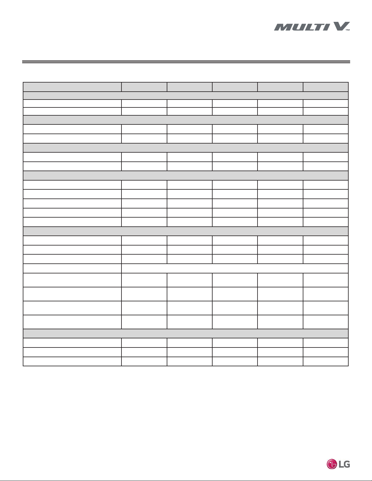
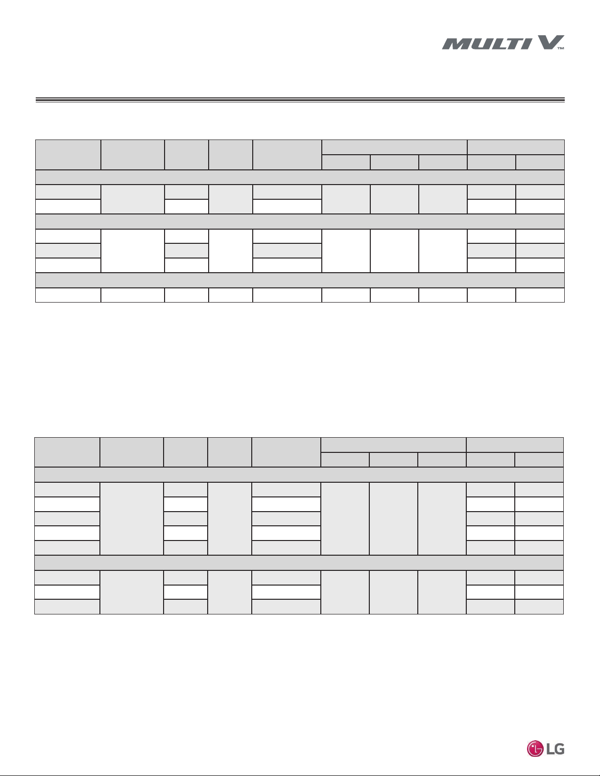
Table 3: High-Static BG Chassis IDU Specications
GENERAL DATA
1
Power Input is rated at high speed.
2
Take appropriate actions at the end of HVAC equipment life to recover, recycle, reclaim or
destroy R410A refrigerant according to applicable regulations (40 CFR Part 82, Subpart F)
under section 608 of CAA.
3
All communication cable to be minimum 18 AWG, 2-conductor, stranded, shielded and
must comply with applicable local and national codes. Ensure the communication cable
is properly grounded at the master outdoor unit only. Do not ground the ODU−IDU com-
munications cable at any other point.
EEV: Electronic Expansion Valve
Power wiring is field supplied and must comply with the applicable local and national
codes. Power Supply (V/Hz/Ø): 208-230/60/1
This unit comes with a dry nitrogen charge.
This data is rated 0 ft above sea level, with 25 ft of refrigerant line per indoor unit and a 0 ft
level difference between outdoor and indoor units. All capacities are net with a combina-
tion ratio between 95-105%.
Cooling capacity rating obtained with air entering the indoor coil at 80ºF dry bulb (DB) and
67ºF wet bulb (WB) and outdoor ambient conditions of 95ºF dry bulb (DB).
Heating capacity rating obtained with air entering the indoor unit at 70ºF dry bulb (DB) and
outdoor ambient conditions of 47ºF dry bulb (DB) and 43ºF wet bulb (WB).
Specications − High-Static BG Chassis
Model No. ARNU073BGA4 ARNU093BGA4 ARNU123BGA4 ARNU153BGA4 ARNU183BGA4
Cooling Mode Performance
Capacity (Btu/h)
7,500 9,600 12,300 15,400 19,100
Power Input
1
(W)
450 450 450 450 450
Heating Mode Performance
Capacity (Btu/h)
8,500 10,900 13,600 17,100 21,500
Power Input
1
(W)
450 450 450 450 450
Entering Mixed Air
Cooling Max. (°F WB)
76 76 76 76 76
Heating Min. (°F DB)
59 59 59 59 59
Unit Data
Refrigerant Type
2
R410A R410A R410A R410A R410A
Refrigerant Control
EEV EEV EEV EEV EEV
Net Unit Weight (lbs.)
83.8 83.8 83.8 83.8 83.8
Shipping Weight (lbs.)
94.8 94.8 94.8 94.8 94.8
Communication Cable
4
(No. x AWG)
2 x 18 2 x 18 2 x 18 2 x 18 2 x 18
Fan
Type
Sirocco Sirocco Sirocco Sirocco Sirocco
Motor
1 1 1 1 1
Housing
2 2 2 2 2
Motor/Drive
Brushless Digitally Controlled / Direct
Airflow Rate H/M/L (CFM)
Standard Mode
516 / 484 / 434 533 / 484 / 434 586 / 533 / 484 477 / 427 / 318 547 / 470 / 427
Airflow Rate H/M/L (CFM)
High Mode (Factory Set)
441 / 406 / 332 452 / 406 / 332 477 / 427 / 332 487 / 417 / 293 537 / 487 / 417
External Static Pressure (in. wg)
Standard Mode
0.15 0.15 0.15 0.23 0.23
External Static Pressure (in. wg)
High Mode (Factory Set)
0.23 0.23 0.23 0.31 0.31
Piping
Liquid Line (in., O.D.)
3/8 Flare 3/8 Flare 3/8 Flare 3/8 Flare 3/8 Flare
Vapor Line (in., O.D.)
5/8 Flare 5/8 Flare 5/8 Flare 5/8 Flare 5/8 Flare
Condensate Line (in., I.D.)
1 1 1 1 1

15
Installation Manual
Due to our policy of continuous product innovation, some specifications may change without notification.
©LG Electronics U.S.A., Inc., Englewood Cliffs, NJ. All rights reserved. “LG” is a registered trademark of LG Corp.
GENERAL DATA
Table 2: High-Static BG Chassis IDU Specications – continued
1
Power Input is rated at high speed.
2
Take appropriate actions at the end of HVAC equipment life to recover, recycle, reclaim or
destroy R410A refrigerant according to applicable regulations (40 CFR Part 82, Subpart F)
under section 608 of CAA.
3
All communication cable to be minimum 18 AWG, 2-conductor, stranded, shielded and
must comply with applicable local and national codes. Ensure the communication cable
is properly grounded at the master outdoor unit only. Do not ground the ODU−IDU com-
munications cable at any other point.
EEV: Electronic Expansion Valve
Power wiring is field supplied and must comply with the applicable local and national
codes. Power Supply (V/Hz/Ø): 208-230/60/1
This unit comes with a dry nitrogen charge.
This data is rated 0 ft above sea level, with 25 ft of refrigerant line per indoor unit and a 0 ft
level difference between outdoor and indoor units. All capacities are net with a combina-
tion ratio between 95-105%.
Cooling capacity rating obtained with air entering the indoor coil at 80ºF dry bulb (DB) and
67ºF wet bulb (WB) and outdoor ambient conditions of 95ºF dry bulb (DB).
Heating capacity rating obtained with air entering the indoor unit at 70ºF dry bulb (DB) and
outdoor ambient conditions of 47ºF dry bulb (DB) and 43ºF wet bulb (WB).
Specications − High-Static BG Chassis
Model No. ARNU243BGA4 ARNU283BGA4 ARNU363BGA4 ARNU423BGA4
Cooling Mode Performance
Capacity (Btu/h)
24,200 28,000 36,200 42,000
Power Input
1
(W)
450 450 450 450
Heating Mode Performance
Capacity (Btu/h)
27,300 31,500 40,600 43,800
Power Input
1
(W)
450 450 450 450
Entering Mixed Air
Cooling Max. (°F WB)
76 76 76 76
Heating Min. (°F DB)
59 59 59 59
Unit Data
Refrigerant Type
2
R410A R410A R410A R410A
Refrigerant Control
EEV EEV EEV EEV
Net Unit Weight (lbs.)
83.8 83.8 83.8 83.8
Shipping Weight (lbs.)
94.8 94.8 94.8 94.8
Communication Cable
4
(No. x AWG)
2 x 18 2 x 18 2 x 18 2 x 18
Fan
Type
Sirocco Sirocco Sirocco Sirocco
Motor
1 1 1 1
Housing
2 2 2 2
Motor/Drive
Brushless Digitally Controlled / Direct
Airflow Rate H/M/L (CFM)
Standard Mode
671 / 576 / 547 893 / 770 / 622 1,003 / 894 / 770 1,130 / 1,003 / 961
Airflow Rate H/M/L (CFM)
High Mode (Factory Set)
671 / 537 / 487 915 / 851 / 770 1,141 / 1,024 / 894 1,218 / 1,141 / 1,084
External Static Pressure (in. wg)
Standard Mode
0.23 0.31 0.31 0.31
External Static Pressure (in. wg)
High Mode (Factory Set)
0.31 0.39 0.39 0.39
Piping
Liquid Line (in., O.D.)
3/8 Flare 3/8 Flare 3/8 Flare 3/8 Flare
Vapor Line (in., O.D.)
5/8 Flare 5/8 Flare 5/8 Flare 5/8 Flare
Condensate Line (in., I.D.)
1 1 1 1

16
Multi V Ducted Indoor Units
Due to our policy of continuous product innovation, some specifications may change without notification.
©LG Electronics U.S.A., Inc., Englewood Cliffs, NJ. All rights reserved. “LG” is a registered trademark of LG Corp.
GENERAL DATA
1
Power Input is rated at high speed.
2
Take appropriate actions at the end of HVAC equipment life to recover, recycle, reclaim or
destroy R410A refrigerant according to applicable regulations (40 CFR Part 82, Subpart F)
under section 608 of CAA.
3
All communication cable to be minimum 18 AWG, 2-conductor, stranded, shielded and
must comply with applicable local and national codes. Ensure the communication cable
is properly grounded at the master outdoor unit only. Do not ground the ODU−IDU com-
munications cable at any other point.
EEV: Electronic Expansion Valve
Power wiring is field supplied and must comply with the applicable local and national
codes. Power Supply (V/Hz/Ø): 208-230/60/1
This unit comes with a dry nitrogen charge.
This data is rated 0 ft above sea level, with 25 ft of refrigerant line per indoor unit and a 0 ft
level difference between outdoor and indoor units. All capacities are net with a combina-
tion ratio between 95-105%.
Cooling capacity rating obtained with air entering the indoor coil at 80ºF dry bulb (DB) and
67ºF wet bulb (WB) and outdoor ambient conditions of 95ºF dry bulb (DB).
Heating capacity rating obtained with air entering the indoor unit at 70ºF dry bulb (DB) and
outdoor ambient conditions of 47ºF dry bulb (DB) and 43ºF wet bulb (WB).
Specications − High-Static BR/B8 Chassis
Table 4: High-Static BR Chassis IDU Specications
Model No. ARNU283BRA4 ARNU363BRA4 ARNU5423BRA4 ARNU483BRA4 ARNU543BRA4
Cooling Mode Performance
Capacity (Btu/h)
28,000 36,200 42,000 48,100 54,000
Power Input
1
(W)
450 450 450 450 450
Heating Mode Performance
Capacity (Btu/h)
31,500 40,600 43,800 51,200 61,400
Power Input
1
(W)
450 450 450 450 450
Entering Mixed Air
Cooling Max. (°F WB)
76 76 76 76 76
Heating Min. (°F DB)
59 59 59 59 59
Unit Data
Refrigerant Type
2
R410A R410A R410A R410A R410A
Refrigerant Control
EEV EEV EEV EEV EEV
Net Unit Weight (lbs.)
112 112 112 112 112
Shipping Weight (lbs.)
132 132 132 132 132
Communication Cable
4
(No. x AWG)
2 x 18 2 x 18 2 x 18 2 x 18 2 x 18
Fan
Type
Sirocco Sirocco Sirocco Sirocco Sirocco
Motor
2 2 2 2 2
Housing
2 2 2 2 2
Motor/Drive
Brushless Digitally Controlled / Direct
Airflow Rate H/M/L (CFM)
Standard Mode
1,151 / 1,105 / 1,074 1,430 / 1,151 / 1,105 1,497 / 1,430 / 1,151 1,568 /1,395 /1,183 1,819 /1,678 /1,395
Airflow Rate H/M/L (CFM)
High Mode (Factory Set)
1,278 / 1,134 / 1,007 1,381 / 1,176 / 1,049 1,490 / 1,381 / 1,176 1,582/ 1,434 /1,176 1,801 / 1,582/ 1,434
External Static Pressure (in. wg)
Standard Mode
0.39 0.39 0.39 0.39 0.39
External Static Pressure (in. wg)
High Mode (Factory Set)
0.55 0.55 0.55 0.55 0.55
Piping
Liquid Line (in., O.D.)
3/8 Flare 3/8 Flare 3/8 Flare 3/8 Flare 3/8 Flare
Vapor Line (in., O.D.)
5/8 Flare 5/8 Flare 5/8 Flare 5/8 Flare 5/8 Flare
Condensate Line (in., I.D.)
1 1 1 1 1

17
Installation Manual
Due to our policy of continuous product innovation, some specifications may change without notification.
©LG Electronics U.S.A., Inc., Englewood Cliffs, NJ. All rights reserved. “LG” is a registered trademark of LG Corp.
Table 5: High-Static B8 Chassis IDU Specications
Model No. ARNU363B8A4 ARNU423B8A4 ARNU483B8A4 ARNU763B8A4 ARNU963B8A4
Cooling Mode Performance
Capacity (Btu/h)
36,200 42,000 48,100 76,400 95,900
Power Input
1
(W)
800 800 800 800 800
Heating Mode Performance
Capacity (Btu/h)
40,600 43,800 51,200 86,000 107,500
Power Input
1
(W)
800 800 800 800 800
Entering Mixed Air
Cooling Max. (°F WB)
76 76 76 76 76
Heating Min. (°F DB)
59 59 59 59 59
Unit Data
Refrigerant Type
2
R410A R410A R410A R410A R410A
Refrigerant Control
EEV EEV EEV EEV EEV
Net Unit Weight (lbs.)
192 192 192 192 192
Shipping Weight (lbs.)
222 222 222 222 222
Communication Cable
4
(No. x AWG)
2 x 18 2 x 18 2 x 18 2 x 18 2 x 18
Fan
Type
Sirocco Sirocco Sirocco Sirocco Sirocco
Motor
2 2 2 2 2
Housing
2 2 2 2 2
Motor/Drive
Brushless Digitally Controlled / Direct
Airflow Rate H/M/L (CFM)
Standard Mode
1,896 / 1,748 / 1,550 1,963 / 1,786 / 1,589 2,048 / 1,846 / 1,670 2,050 / 1,766 / 1,766 2,684 / 2,260 / 2,260
Airflow Rate H/M/L (CFM)
High Mode (Factory Set)
1,730 / 1,317 / 1,066 1,914 / 1,458 / 1,123 2,019 / 1,518 / 1,200 2,260 / 1,766 / 1,766 2,542 / 2,260 / 2,260
External Static Pressure (in. wg)
Standard Mode
0.35 0.35 0.35 0.59 0.59
External Static Pressure (in. wg)
High Mode (Factory Set)
0.70 0.70 0.70 0.87 0.87
Piping
Liquid Line (in., O.D.)
3/8 Flare 3/8 Flare 3/8 Flare 3/8 Flare 3/8 Flare
Vapor Line (in., O.D.)
3/4 Brazed 3/4 Brazed 3/4 Brazed 3/4 Flare 7/8 Flare
Condensate Line (in., I.D.)
1 1 1 1 1
1
Power Input is rated at high speed.
2
Take appropriate actions at the end of HVAC equipment life to recover, recycle, reclaim or
destroy R410A refrigerant according to applicable regulations (40 CFR Part 82, Subpart F)
under section 608 of CAA.
3
All communication cable to be minimum 18 AWG, 2-conductor, stranded, shielded and
must comply with applicable local and national codes. Ensure the communication cable
is properly grounded at the master outdoor unit only. Do not ground the ODU−IDU com-
munications cable at any other point.
EEV: Electronic Expansion Valve
Power wiring is field supplied and must comply with the applicable local and national
codes. Power Supply (V/Hz/Ø): 208-230/60/1
This unit comes with a dry nitrogen charge.
This data is rated 0 ft above sea level, with 25 ft of refrigerant line per indoor unit and a 0 ft
level difference between outdoor and indoor units. All capacities are net with a combina-
tion ratio between 95-105%.
Cooling capacity rating obtained with air entering the indoor coil at 80ºF dry bulb (DB) and
67ºF wet bulb (WB) and outdoor ambient conditions of 95ºF dry bulb (DB).
Heating capacity rating obtained with air entering the indoor unit at 70ºF dry bulb (DB) and
outdoor ambient conditions of 47ºF dry bulb (DB) and 43ºF wet bulb (WB).

18
Multi V Ducted Indoor Units
Due to our policy of continuous product innovation, some specifications may change without notification.
©LG Electronics U.S.A., Inc., Englewood Cliffs, NJ. All rights reserved. “LG” is a registered trademark of LG Corp.
GENERAL DATA
1
Power Input is rated at high speed.
2
Take appropriate actions at the end of HVAC equipment life to recover, recycle, reclaim or
destroy R410A refrigerant according to applicable regulations (40 CFR Part 82, Subpart F)
under section 608 of CAA.
3
All communication cable to be minimum 18 AWG, 2-conductor, stranded, shielded and
must comply with applicable local and national codes. Ensure the communication cable
is properly grounded at the master outdoor unit only. Do not ground the ODU−IDU com-
munications cable at any other point.
EEV: Electronic Expansion Valve
Power wiring is field supplied and must comply with the applicable local and national
codes. Power Supply (V/Hz/Ø): 208-230/60/1
This unit comes with a dry nitrogen charge.
This data is rated 0 ft above sea level, with 25 ft of refrigerant line per indoor unit and a 0 ft
level difference between outdoor and indoor units. All capacities are net with a combina-
tion ratio between 95-105%.
Cooling capacity rating obtained with air entering the indoor coil at 80ºF dry bulb (DB) and
67ºF wet bulb (WB) and outdoor ambient conditions of 95ºF dry bulb (DB).
Heating capacity rating obtained with air entering the indoor unit at 70ºF dry bulb (DB) and
outdoor ambient conditions of 47ºF dry bulb (DB) and 43ºF wet bulb (WB).
Specications − Low-Static B3/B4 Chassis
Table 6: Low-Static Built-In B3/B4 Chassis IDU Specications
Model No. ARNU073B3G4 ARNU093B3G4 ARNU123B3G4 ARNU153B3G4 ARNU183B4G4 ARNU243B4G4
Cooling Mode Performance
Capacity (Btu/h)
7,500 9,600 12,300 15,400 19,100 24,200
Power Input
1
(W)
85 85 85 85 85 115
Heating Mode Performance
Capacity (Btu/h)
8,500 10,900 13,600 17,100 21,500 27,300
Power Input
1
(W)
85 85 85 85 85 115
Entering Mixed Air
Cooling Max. (°F WB)
76 76 76 76 76 76
Heating Min. (°F DB)
59 59 59 59 59 59
Unit Data
Refrigerant Type
2
R410A R410A R410A R410A R410A R410A
Refrigerant Control
EEV EEV EEV EEV EEV EEV
Net Unit Weight (lbs.)
46.3 46.3 46.3 46.3 57.3 57.3
Shipping Weight (lbs.)
53.3 53.3 53.3 53.3 67.2 67.2
Communication Cable
4
(No. x AWG)
2 x 18 2 x 18 2 x 18 2 x 18 2 x 18 2 x 18
Fan
Type
Sirocco Sirocco Sirocco Sirocco Sirocco Sirocco
Motor
2 2 2 2 2 2
Housing
3 3 3 3 4 4
Motor/Drive
Brushless Digitally Controlled / Direct
Airflow Rate H/M/L (CFM)
Standard Mode
283 / 229 / 194 318 / 247 / 212 353 / 283 / 229 388 / 353 / 283 494 / 424 / 353 600 / 530 / 353
Airflow Rate H/M/L (CFM)
High Mode (Factory Set)
283 / 229 / 194 318 / 247 / 212 353 / 283 / 229 388 / 353 / 283 494 / 424 / 353 600 / 530 / 353
External Static Pressure (in. wg)
Standard Mode
0 0 0 0 0 0
External Static Pressure (in. wg)
High Mode (Factory Set)
0.08 0.08 0.08 0.08 0.08 0.08
Piping
Liquid Line (in., O.D.)
1/4 Flare 1/4 Flare 1/4 Flare 1/4 Flare 1/4 Flare 3/8 Flare
Vapor Line (in., O.D.)
1/2 Flare 1/2 Flare 1/2 Flare 1/2 Flare 1/2 Flare 5/8 Flare
Condensate Line (in., I.D.)
1 1 1 1 1 1

19
Installation Manual
Due to our policy of continuous product innovation, some specifications may change without notification.
©LG Electronics U.S.A., Inc., Englewood Cliffs, NJ. All rights reserved. “LG” is a registered trademark of LG Corp.
1
Power Input is rated at high speed.
2
Take appropriate actions at the end of HVAC equipment life to recover, recycle, reclaim or
destroy R410A refrigerant according to applicable regulations (40 CFR Part 82, Subpart F)
under section 608 of CAA.
3
All communication cable to be minimum 18 AWG, 2-conductor, stranded, shielded and
must comply with applicable local and national codes. Ensure the communication cable
is properly grounded at the master outdoor unit only. Do not ground the ODU−IDU com-
munications cable at any other point.
EEV: Electronic Expansion Valve
Power wiring is field supplied and must comply with the applicable local and national
codes. Power Supply (V/Hz/Ø): 208-230/60/1
This unit comes with a dry nitrogen charge.
This data is rated 0 ft above sea level, with 25 ft of refrigerant line per indoor unit and a 0 ft
level difference between outdoor and indoor units. All capacities are net with a combina-
tion ratio between 95-105%.
Cooling capacity rating obtained with air entering the indoor coil at 80ºF dry bulb (DB) and
67ºF wet bulb (WB) and outdoor ambient conditions of 95ºF dry bulb (DB).
Heating capacity rating obtained with air entering the indoor unit at 70ºF dry bulb (DB) and
outdoor ambient conditions of 47ºF dry bulb (DB) and 43ºF wet bulb (WB).
Table 7: Low-Static Ducted L1/L2/L3 Chassis IDU Specications
GENERAL DATA
Specications − Low-Static Ducted L1/L2/L3 Chassis
Model No. ARNU073L1G4 ARNU093L1G4 ARNU123L2G4 ARNU153L2G4 ARNU183L2G4 ARNU243L3G4
Cooling Mode Performance
Capacity (Btu/h)
7,500 9,600 12,300 15,400 19,100 24,000
Power Input
1
(W)
40 40 85 85 85 115
Heating Mode Performance
Capacity (Btu/h)
8,500 10,900 13,600 17,100 21,500 27,300
Power Input
1
(W)
40 40 85 85 85 115
Entering Mixed Air
Cooling Max. (°F WB)
76 76 76 76 76 76
Heating Min. (°F DB)
59 59 59 59 59 59
Unit Data
Refrigerant Type
2
R410A R410A R410A R410A R410A R410A
Refrigerant Control
EEV EEV EEV EEV EEV EEV
Net Unit Weight (lbs.)
38.6 38.6 50.7 50.7 50.7 59.5
Shipping Weight (lbs.)
47.4 47.4 60.6 60.6 60.6 68.3
Communication Cable
4
(No. x AWG)
2 x 18 2 x 18 2 x 18 2 x 18 2 x 18 2 x 18
Fan
Type
Sirocco Sirocco Sirocco Sirocco Sirocco Sirocco
Motor
1 1 2 2 2 2
Housing
2 2 3 3 3 4
Motor/Drive
Brushless Digitally Controlled / Direct
Airflow Rate H/M/L (CFM)
Standard Mode
270 / 230 / 200 320 / 250 / 200 360 / 310 / 250 450 / 360 / 310 530 / 450 / 360 710 / 570 / 430
Airflow Rate H/M/L (CFM)
High Mode (Factory Set)
270 / 230 / 200 320 / 250 / 200 360 / 310 / 250 450 / 360 / 310 530 / 450 / 360 710 / 570 / 430
External Static Pressure (in. wg)
Standard Mode
0 0 0 0 0 0
External Static Pressure (in. wg)
High Mode (Factory Set)
0.1 0.1 0.1 0.1 0.1 0.1
Piping
Liquid Line (in., O.D.)
1/4 Flare 1/4 Flare 1/4 Flare 1/4 Flare 1/4 Flare 3/8 Flare
Vapor Line (in., O.D.)
1/2 Flare 1/2 Flare 1/2 Flare 1/2 Flare 1/2 Flare 5/8 Flare
Condensate Line (in., I.D.)
1 1 1 1 1 1
20
Multi V Ducted Indoor Units
Due to our policy of continuous product innovation, some specifications may change without notification.
©LG Electronics U.S.A., Inc., Englewood Cliffs, NJ. All rights reserved. “LG” is a registered trademark of LG Corp.
1
Power Input is rated at high speed.
2
Take appropriate actions at the end of HVAC equipment life to recover, recycle, reclaim or
destroy R410A refrigerant according to applicable regulations (40 CFR Part 82, Subpart F)
under section 608 of CAA.
3
All communication cable to be minimum 18 AWG, 2-conductor, stranded, shielded and
must comply with applicable local and national codes. Ensure the communication cable
is properly grounded at the master outdoor unit only. Do not ground the ODU−IDU com-
munications cable at any other point.
EEV: Electronic Expansion Valve
Power wiring is field supplied and must comply with the applicable local and national
codes. Power Supply (V/Hz/Ø): 208-230/60/1
This unit comes with a dry nitrogen charge.
This data is rated 0 ft above sea level, with 25 ft of refrigerant line per indoor unit and a 0 ft
level difference between outdoor and indoor units. All capacities are net with a combina-
tion ratio between 95-105%.
Cooling capacity rating obtained with air entering the indoor coil at 80ºF dry bulb (DB) and
67ºF wet bulb (WB) and outdoor ambient conditions of 95ºF dry bulb (DB).
Heating capacity rating obtained with air entering the indoor unit at 70ºF dry bulb (DB) and
outdoor ambient conditions of 47ºF dry bulb (DB) and 43ºF wet bulb (WB).
Table 8: Vertical Air Handler NJ Chassis IDU Specications
Model No. ARNU123NJA4 ARNU183NJA4 ARNU243NJA4 ARNU303NJA4 ARNU363NJA4
Cooling Mode Performance
Capacity (Btu/h)
12,000 18,000 24,000 30,000 36,000
Power Input
1
(W)
80 80 120 178 228
Heating Mode Performance
Capacity (Btu/h)
13,500 20,000 27,000 34,000 40,000
Power Input
1
(W)
80 80 120 178 228
Entering Mixed Air
Cooling Max. (°F WB)
76 76 76 76 76
Heating Min. (°F DB)
59 59 59 59 59
Unit Data
Refrigerant Type
2
R410A R410A R410A R410A R410A
Refrigerant Control
EEV EEV EEV EEV EEV
Net Unit Weight (lbs.)
117 117 117 117 121
Shipping Weight (lbs.)
140 140 140 140 144
Communication Cable
4
(No. x AWG)
2 x 18 2 x 18 2 x 18 2 x 18 2 x 18
Fan
Type
Sirocco Sirocco Sirocco Sirocco Sirocco
Motor
1 1 1 1 1
Housing
1 1 1 1 1
Motor/Drive
Brushless Digitally Controlled / Direct
Airflow Rate H/M/L (CFM)
Standard Mode
530 / 480 / 380 580 / 530 / 480 710 / 640 / 480 880 / 800 / 630 990 / 880 / 800
Airflow Rate H/M/L (CFM)
High Mode (Factory Set)
530 / 480 / 380 580 / 530 / 480 710 / 640 / 480 880 / 800 / 630 990 / 880 / 800
External Static Pressure (in. wg)
Standard Mode
0.3 0.3 0.3 0.3 0.3
External Static Pressure (in. wg)
High Mode (Factory Set)
0.5 0.5 0.5 0.5 0.5
Piping
Liquid Line (in., O.D.)
1/4 Flare 1/4 Flare 3/8 Flare 3/8 Flare 3/8 Flare
Vapor Line (in., O.D.)
1/2 Flare 1/2 Flare 5/8 Flare 5/8 Flare 5/8 Flare
Condensate Line (in., I.D.)
1 1 1 1 1
GENERAL DATA
Specications − Vertical Air Handler NJ Chassis

21
Installation Manual
Due to our policy of continuous product innovation, some specifications may change without notification.
©LG Electronics U.S.A., Inc., Englewood Cliffs, NJ. All rights reserved. “LG” is a registered trademark of LG Corp.
GENERAL DATA
Specications − Vertical Air Handler NK Chassis
1
Power Input is rated at high speed.
2
Take appropriate actions at the end of HVAC equipment life to recover, recycle, reclaim or
destroy R410A refrigerant according to applicable regulations (40 CFR Part 82, Subpart F)
under section 608 of CAA.
3
All communication cable to be minimum 18 AWG, 2-conductor, stranded, shielded and
must comply with applicable local and national codes. Ensure the communication cable
is properly grounded at the master outdoor unit only. Do not ground the ODU−IDU com-
munications cable at any other point.
EEV: Electronic Expansion Valve
Power wiring is field supplied and must comply with the applicable local and national
codes. Power Supply (V/Hz/Ø): 208-230/60/1
This unit comes with a dry nitrogen charge.
This data is rated 0 ft above sea level, with 25 ft of refrigerant line per indoor unit and a 0 ft
level difference between outdoor and indoor units. All capacities are net with a combina-
tion ratio between 95-105%.
Cooling capacity rating obtained with air entering the indoor coil at 80ºF dry bulb (DB) and
67ºF wet bulb (WB) and outdoor ambient conditions of 95ºF dry bulb (DB).
Heating capacity rating obtained with air entering the indoor unit at 70ºF dry bulb (DB) and
outdoor ambient conditions of 47ºF dry bulb (DB) and 43ºF wet bulb (WB).
Table 9: Vertical Air Handler NK Chassis IDU Specications
Model No. ARNU423NKA4 ARNU483NKA4 ARNU543NKA4
Cooling Mode Performance
Capacity (Btu/h)
42,000 48,000 54,000
Power Input
1
(W)
260 330 366
Heating Mode Performance
Capacity (Btu/h)
46,000 54,000 60,000
Power Input
1
(W)
260 330 366
Entering Mixed Air
Cooling Max. (°F WB)
76 76 76
Heating Min. (°F DB)
59 59 59
Unit Data
Refrigerant Type
2
R410A R410A R410A
Refrigerant Control
EEV EEV EEV
Net Unit Weight (lbs.)
165 165 165
Shipping Weight (lbs.)
181 181 181
Communication Cable
4
(No. x AWG)
2 x 18 2 x 18 2 x 18
Fan
Type
Sirocco Sirocco Sirocco
Motor
1 1 1
Housing
1 1 1
Motor/Drive
Brushless Digitally Controlled / Direct
Airflow Rate H/M/L (CFM)
Standard Mode
1,250 / 1,100 / 1,000 1,400 / 1,260 / 1,000 1,475 / 1,400 / 1,260
Airflow Rate H/M/L (CFM)
High Mode (Factory Set)
1,250 / 1,100 / 1,000 1,400 / 1,260 / 1,000 1,475 / 1,400 / 1,260
External Static Pressure (in. wg)
Standard Mode
0.3 0.3 0.3
External Static Pressure (in. wg)
High Mode (Factory Set)
0.5 0.5 0.5
Piping
Liquid Line (in., O.D.)
3/8 Flare 3/8 Flare 3/8 Flare
Vapor Line (in., O.D.)
5/8 Flare 5/8 Flare 5/8 Flare
Condensate Line (in., I.D.)
1 1 1
22
Multi V Ducted Indoor Units
Due to our policy of continuous product innovation, some specifications may change without notification.
©LG Electronics U.S.A., Inc., Englewood Cliffs, NJ. All rights reserved. “LG” is a registered trademark of LG Corp.
GENERAL DATA
Electrical − High-Static BH/BG/BR/B8 Chassis
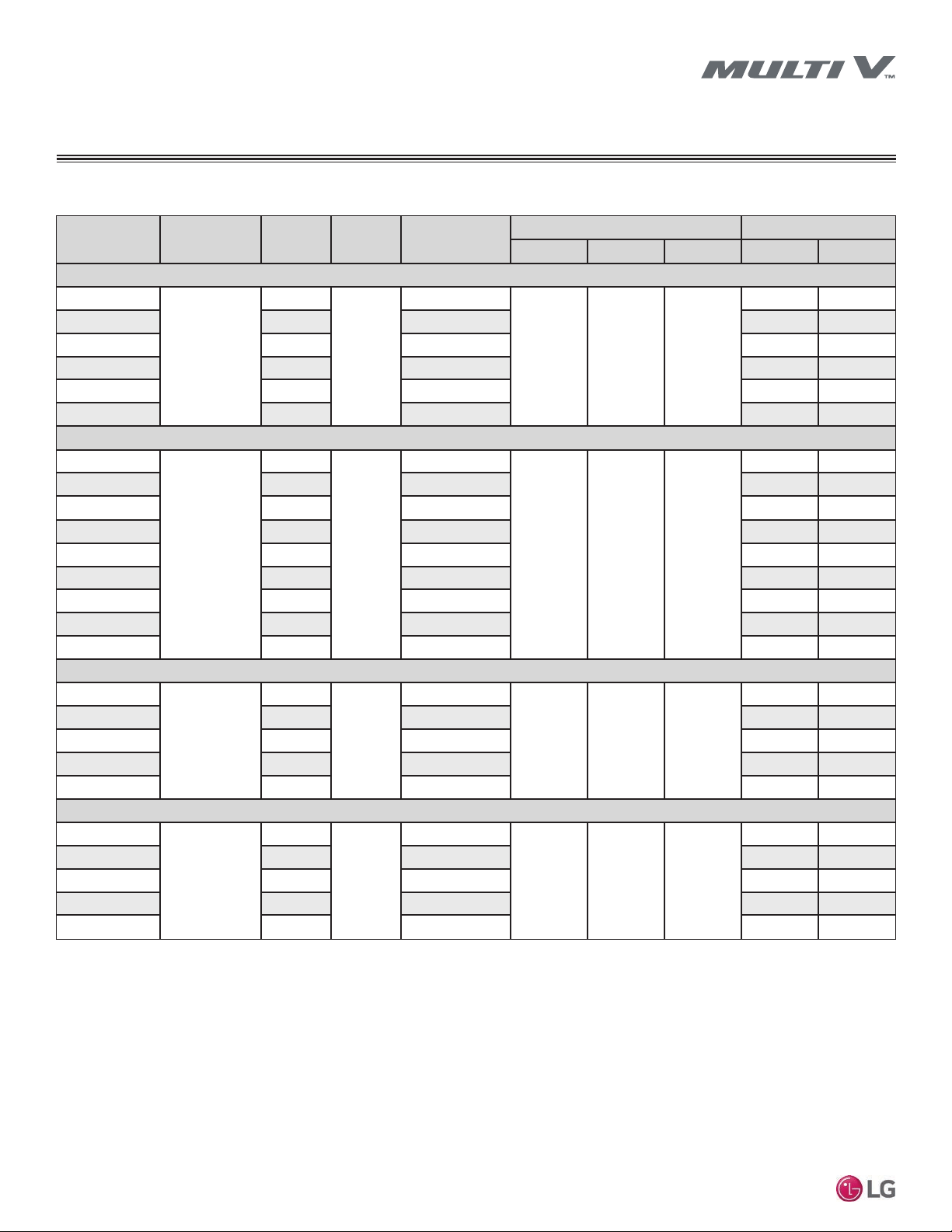
Table 10: High-Static BH/BG/BR/B8 Chassis Indoor Unit Electrical Data.
Model Voltage Range MCA MOP Rated Amps (A)
Power Supply Power Input (W)
Hz Volts Phase Cooling Heating
BH Units
ARNU073BHA4
187-253
1.32
15
1.06
60 208-230 1
150 150
ARNU093BHA4 1.32 1.06 150 150
ARNU123BHA4 1.32 1.06 150 150
ARNU153BHA4 1.32 1.06 150 150
ARNU183BHA4 1.32 1.06 150 150
ARNU243BHA4 1.32 1.06 150 150
BG Units
ARNU073BGA4
187-253
3.3
15
2.65
60 208-230 1
450 450
ARNU093BGA4 3.3 2.65 450 450
ARNU123BGA4
3.3 2.65 450 450
ARNU153BGA4 3.3 2.65 450 450
ARNU183BGA4 3.3 2.65 450 450
ARNU243BGA4 3.3 2.65 450 450
ARNU283BGA4 3.3 2.65 450 450
ARNU363BGA4 3.3 2.65 450 450
ARNU423BGA4 3.3 2.65 450 450
BR Units
ARNU283BRA4
187-253
4.4
15
3.5
60 208-230 1
450 450
ARNU363BRA4 4.4 3.5 450 450
ARNU423BRA4 4.4 3.5 450 450
ARNU483BRA4 4.4 3.5 450 450
ARNU543BRA4 4.4 3.5 450 450
B8 Units
ARNU363B8A4
187-253
6.5
15
5.2
60 208-230 1
800 800
ARNU423B8A4 6.5 5.2 800 800
ARNU483B8A4 6.5 5.2 800 800
ARNU763B8A4 6.5 5.2 800 800
ARNU963B8A4
6.5 5.2 800 800
MCA : Minimum Circuit Ampacity.
MOP : Maximum Overcurrent Protection.
Units are suitable for use on an electrical system where voltage supplied to unit terminals is within the listed range limits.
Select wire size based on the larger MCA value.
Instead of fuse, use circuit breaker.
23
Installation Manual
Due to our policy of continuous product innovation, some specifications may change without notification.
©LG Electronics U.S.A., Inc., Englewood Cliffs, NJ. All rights reserved. “LG” is a registered trademark of LG Corp.
GENERAL DATA
Electrical − Low-Static Built-In B3/B4 Chassis
Table 11: Low-Static Built-In B3/B4 Chassis Electrical Data.
Model Voltage Range MCA MOP Rated Amps (A)
Power Supply Power Input (W)
Hz Volts Phase Cooling Heating
B3 Units
ARNU073B3G4
187-253
1.0
15
0.76
60 208-230 1
85 85
ARNU093B3G4 1.0 0.76 85 85
ARNU123B3G4 1.0 0.76 85 85
ARNU153B3G4 1.0 0.76 85 85
B4 Units
ARNU183B4G4
187-253
1.2
15
0.97
60 208-230 1
115 115
ARNU243B4G4 1.2 0.97 115 115
MCA : Minimum Circuit Ampacity.
MOP : Maximum Overcurrent Protection.
Units are suitable for use on an electrical system where voltage supplied to unit terminals is within the listed range limits.
Select wire size based on the larger MCA value.
Instead of fuse, use circuit breaker.
24
Multi V Ducted Indoor Units
Due to our policy of continuous product innovation, some specifications may change without notification.
©LG Electronics U.S.A., Inc., Englewood Cliffs, NJ. All rights reserved. “LG” is a registered trademark of LG Corp.
GENERAL DATA
Electrical − Low-Static Ducted L1/L2/L3 Chassis
Table 12: Low-Static Ducted L1/L2/L3 Chassis Electrical Data.
Model Voltage Range MCA MOP Rated Amps (A)
Power Supply Power Input (W)
Hz Volts Phase Cooling Heating
L1 Units
ARNU073L1G4
208-230
0.5
15
0.4
60 208-230 1
40 40
ARNU093L1G4 0.5 0.4 40 40
L2 Units
ARNU123L2G4
208-230
1.0
15
0.76
60 208-230 1
85 85
ARNU153L2G4 1.0 0.76 85 85
ARNU183L2G4 1.0 0.76 85 85
L3 Units
ARNU243L3G4 208-230 1.2 15 0.97 60 208-230 1 115 115
MCA : Minimum Circuit Ampacity.
MOP : Maximum Overcurrent Protection.
Units are suitable for use on an electrical system where voltage supplied to unit terminals is within the listed range limits.
Select wire size based on the larger MCA value.
Instead of fuse, use circuit breaker.
Table 13: Vertical Air Handler NJ/NK Chassis Electrical Data.
Model Voltage Range MCA MOP Rated Amps (A)
Power Supply Power Input (W)
Hz Volts Phase Cooling Heating
NJ Units
ARNU123NJA4
208-230
1.4
15
1.12
60 208-230 1
228 228
ARNU183NJA4 1.4 1.12 228 228
ARNU243NJA4 1.4 1.12 228 228
ARNU303NJA4 1.4 1.12 228 228
ARNU363NJA4 1.4 1.12 228 228
NK Units
ARNU423NKA4
208-230
2.3
15
1.8
60 208-230 1
366 366
ARNU483NKA4 2.3 1.8 366 366
ARNU543NKA4 2.3 1.8 366 366
MCA : Minimum Circuit Ampacity.
MOP : Maximum Overcurrent Protection.
Units are suitable for use on an electrical system where voltage supplied to unit terminals is within the listed range limits.
Select wire size based on the larger MCA value.
Instead of fuse, use circuit breaker.
25
Installation Manual
Due to our policy of continuous product innovation, some specifications may change without notification.
©LG Electronics U.S.A., Inc., Englewood Cliffs, NJ. All rights reserved. “LG” is a registered trademark of LG Corp.
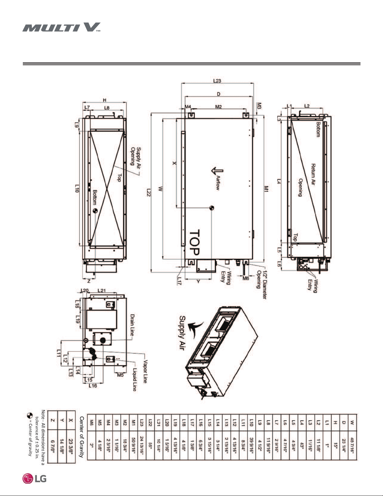
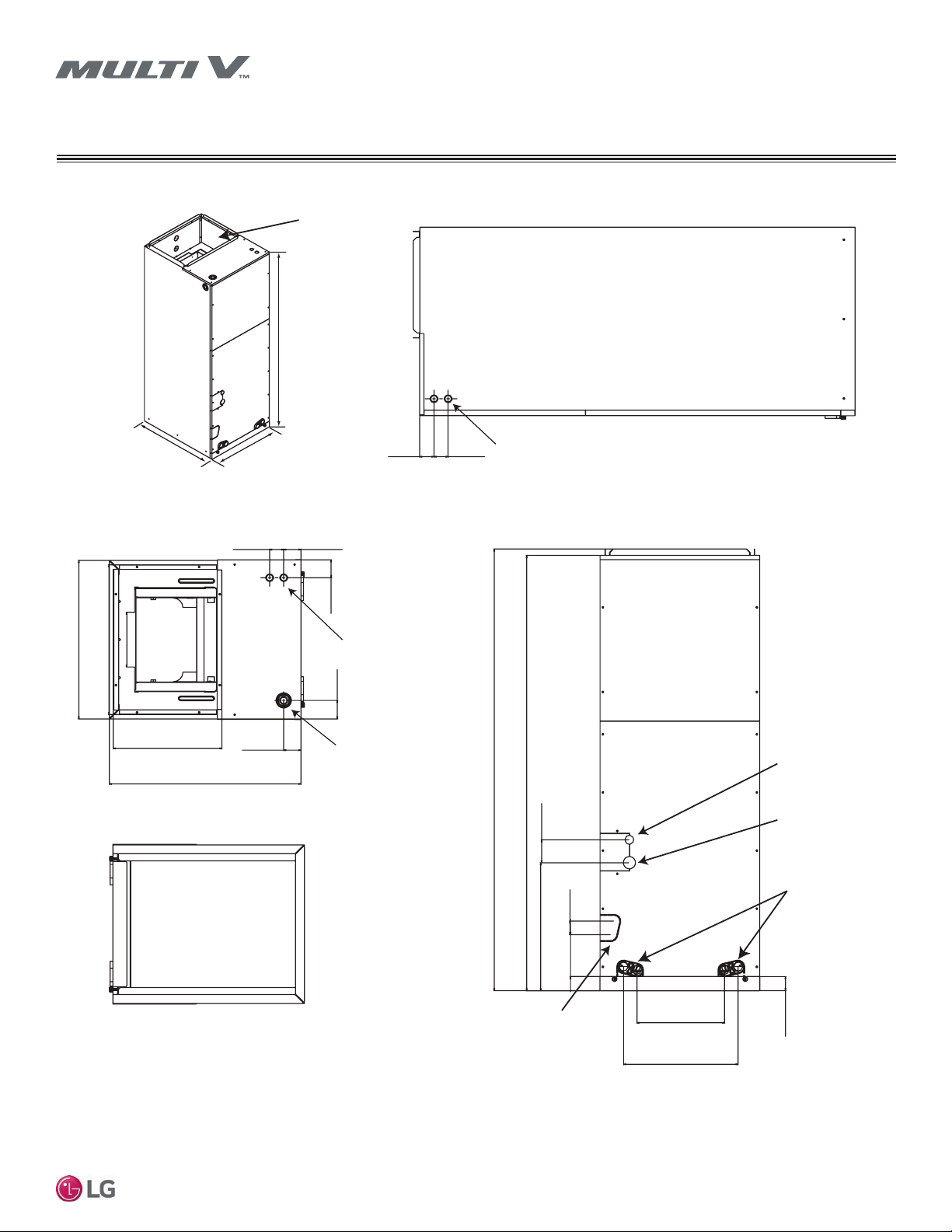
GENERAL DATA
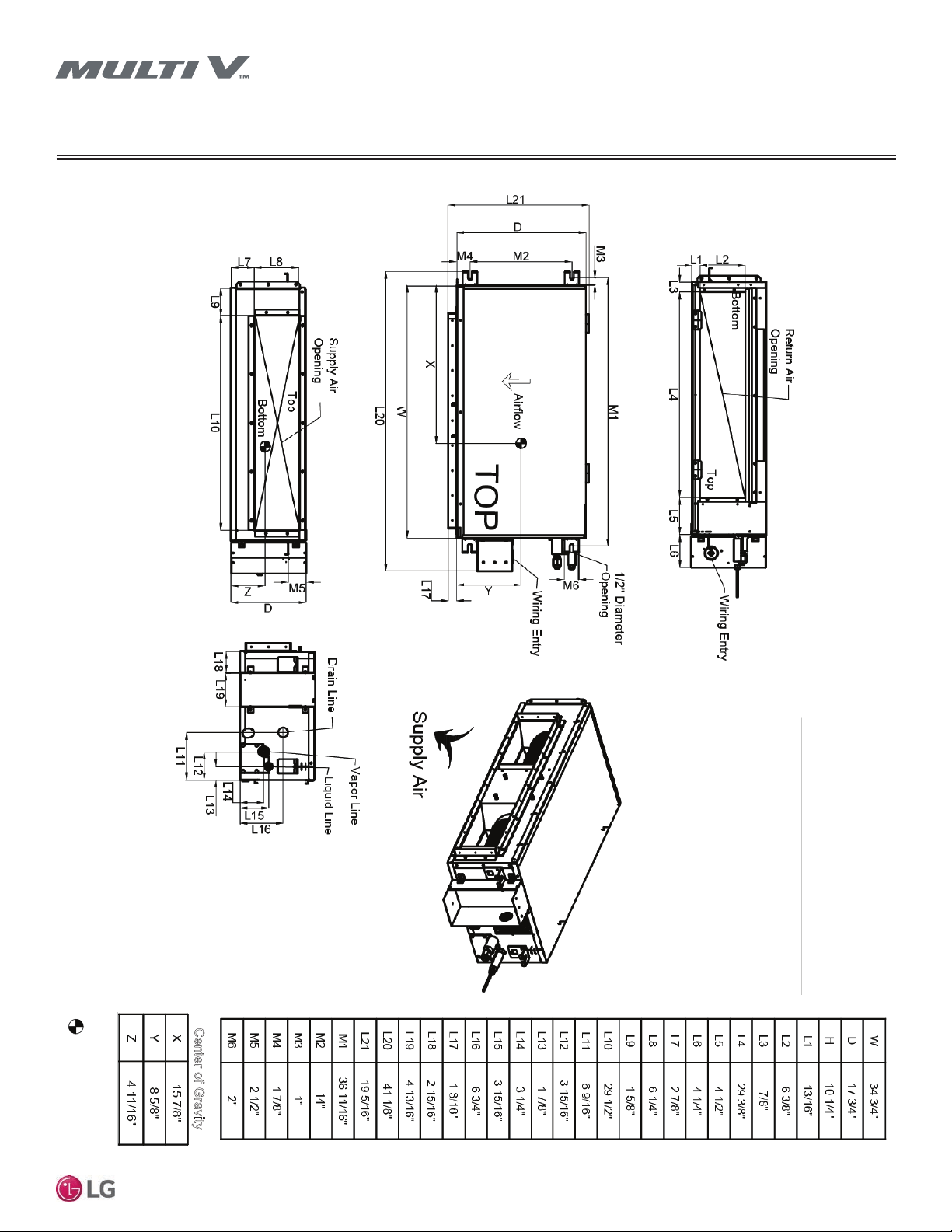
Dimensions – High-Static Ducted BH Chassis
C
ent
e
r of G
r
avity
Note - All dimensions have
a
tolerance of ± 0.25 in.
= Center of gravity
26
Multi V Ducted Indoor Units
Due to our policy of continuous product innovation, some specifications may change without notification.
©LG Electronics U.S.A., Inc., Englewood Cliffs, NJ. All rights reserved. “LG” is a registered trademark of LG Corp.
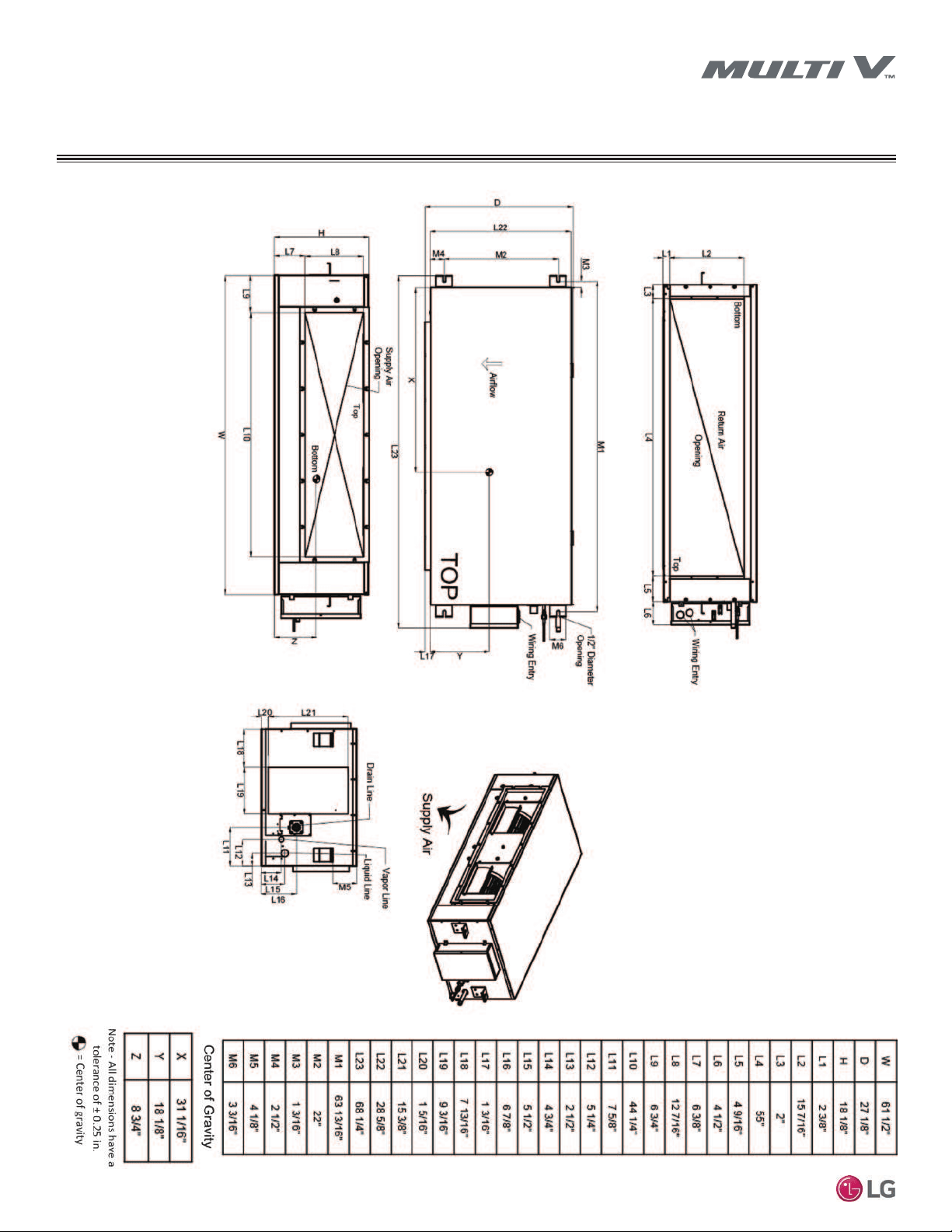
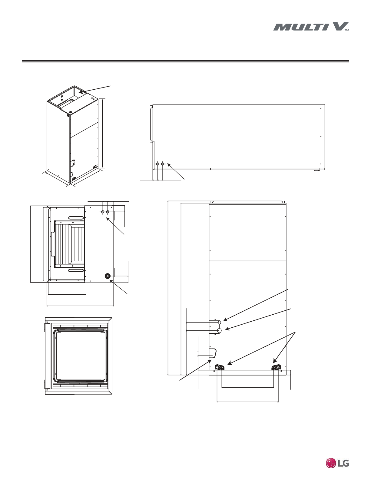
GENERAL DATA
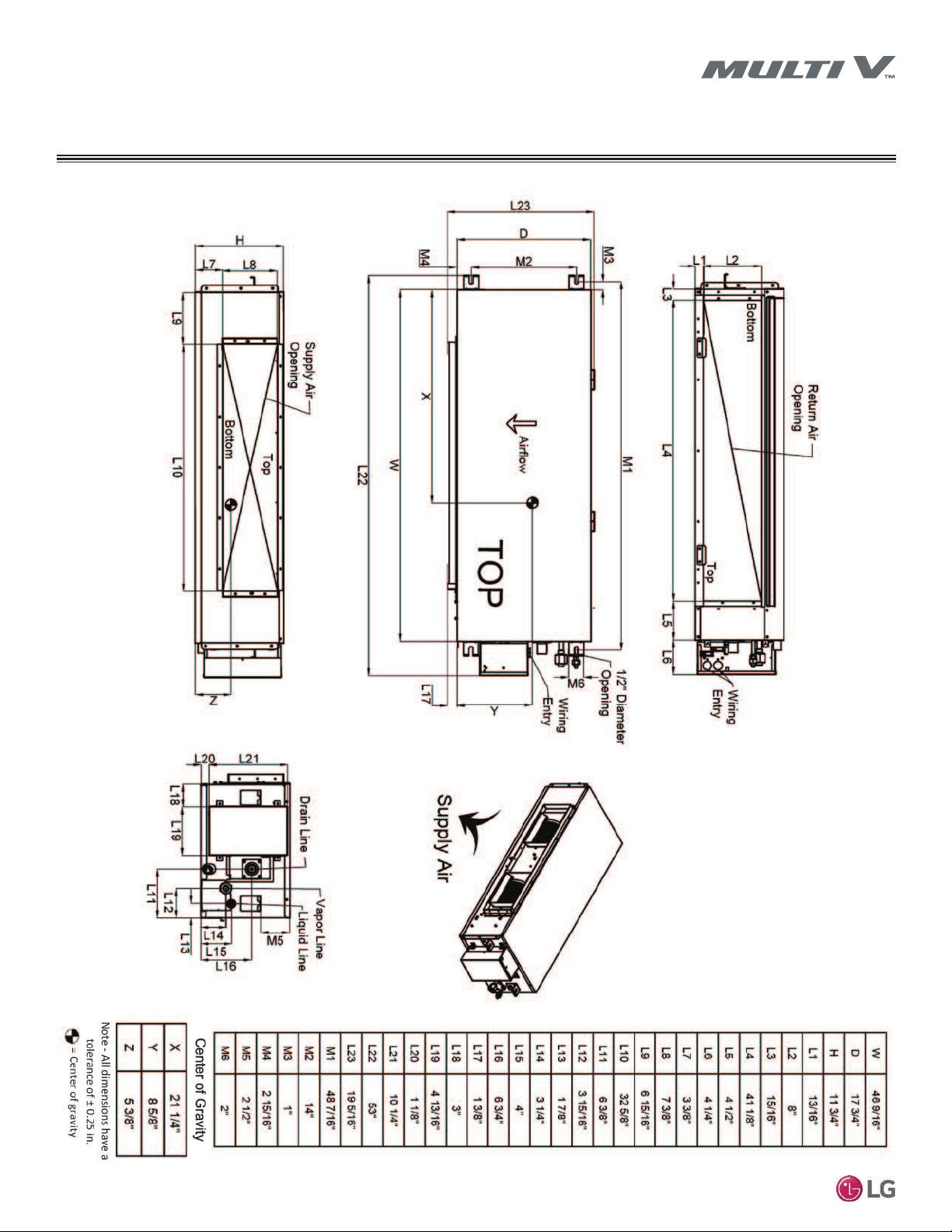
Dimensions – High-Static Ducted BG Chassis
27
Installation Manual
Due to our policy of continuous product innovation, some specifications may change without notification.
©LG Electronics U.S.A., Inc., Englewood Cliffs, NJ. All rights reserved. “LG” is a registered trademark of LG Corp.
GENERAL DATA
Dimensions – High-Static Ducted BR Chassis
28
Multi V Ducted Indoor Units
Due to our policy of continuous product innovation, some specifications may change without notification.
©LG Electronics U.S.A., Inc., Englewood Cliffs, NJ. All rights reserved. “LG” is a registered trademark of LG Corp.
GENERAL DATA
Dimensions – High-Static Ducted B8 Chassis
29
Installation Manual
Due to our policy of continuous product innovation, some specifications may change without notification.
©LG Electronics U.S.A., Inc., Englewood Cliffs, NJ. All rights reserved. “LG” is a registered trademark of LG Corp.
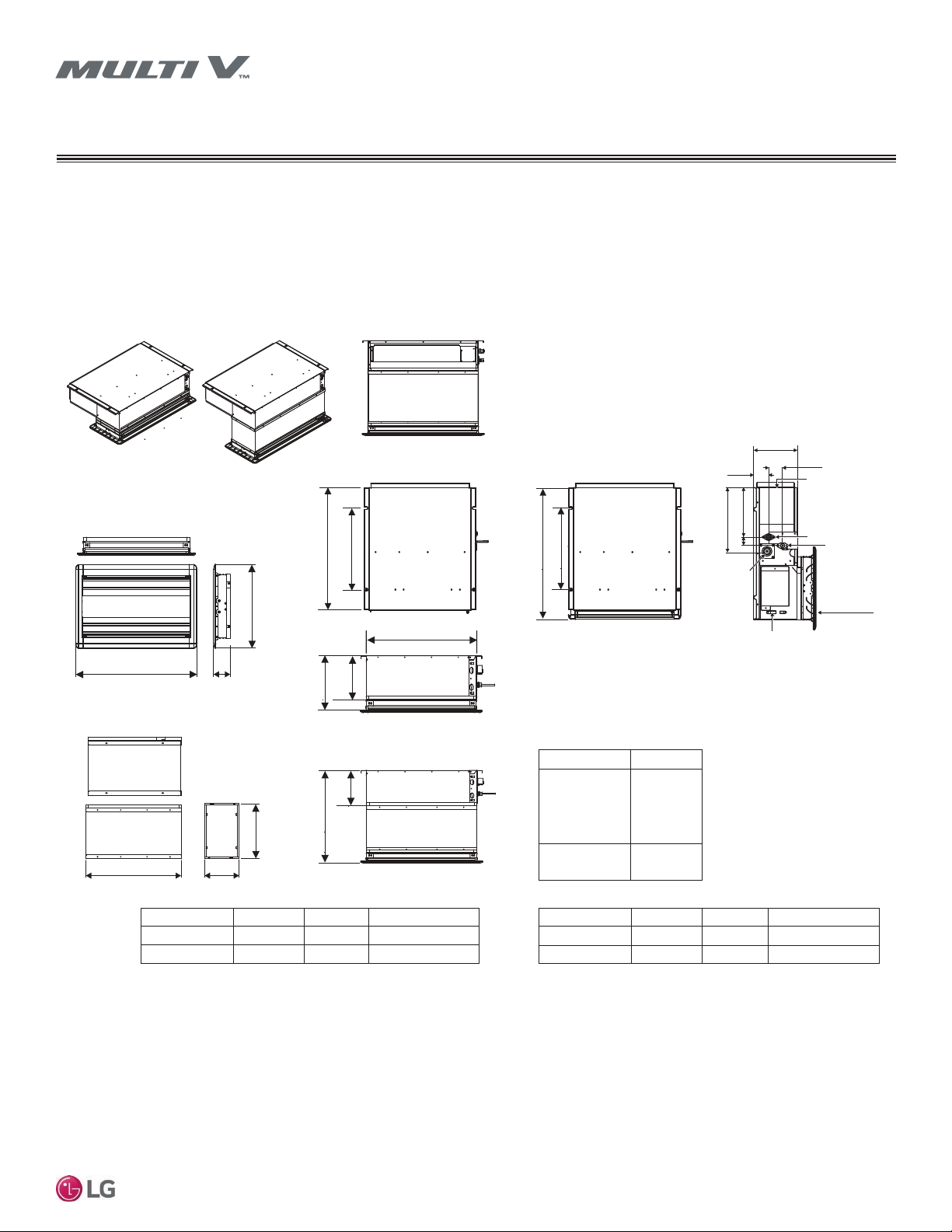
GENERAL DATA
Dimensions – Built-In Low-Static Ducted B3/B4 Chassis
With Suction Grill
With Suction Grill & Suction Canvas
A1
A2 C2
B2
A3
B3
C3
9-13/16
7-7/16
24-5/16
15-1/4
7-1/2
19-11/16 (Max)
22-5/8
15-1/8
7-1/2
2-1/2
2-3/8
10-7/8
8-1/2
Supply Air
Return Air
Power Connection
Liquid
Drain
Vapor
With Suction Grill
& Suction Canvas
With Suction Grill
1
Unit: inches
Note: All measurements
have a tolerance of ±1/4 in.
Accessory
PBSGB30 35-13/16
PBSGB40 46-13/16 14-1/8
A2 B2 C2
2-3/16
14-1/8 2-3/16
PBSC30 32-5/16
PBSC40
Accessory A3 B3 C3
1-9/16 to 9-13/1610-11/16
43-5/16 1-9/16 to 9-13/1610-11/16
Model
32-5/8
43-5/16
A1
ARNU073B3G4
ARNU093B3G4
ARNU123B3G4
ARNU153B3G4
ARNU183B4G4
ARNU243B4G4
With Suction Grill
& Suction Canvas
With Suction Grill
30
Multi V Ducted Indoor Units
Due to our policy of continuous product innovation, some specifications may change without notification.
©LG Electronics U.S.A., Inc., Englewood Cliffs, NJ. All rights reserved. “LG” is a registered trademark of LG Corp.
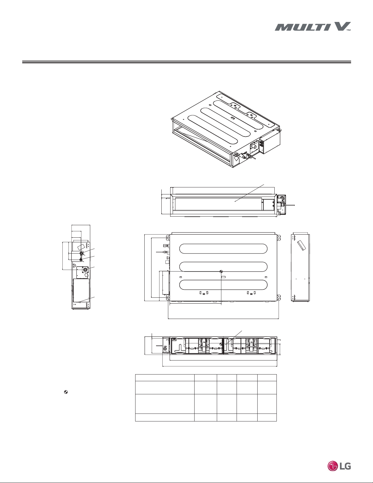
GENERAL DATA
Dimensions – Low-Static Ducted L1/L2/L3 Chassis
30-1/2
ABCD
ARNU073L1G4
ARNU093L1G4
ARNU123L2G4
ARNU153L2G4
ARNU183L2G4
ARNU243L3G4
27-9/16
28-7/8 26
38-3/8 35-7/16 36-3/4 33-7/8
46-1/4
43-5/16
44-5/8 41-3/4
Liquid Pipe Connection
Air Outlet
Air Inlet
11-1/2
2-5/8
4-1/16
7-1/2
L1 : 14-7/16
L2 : 22-1/16
L3 : 29-3/4
3-15/16
3-1/16
27-9/16
7-1/2
13/166-1/16
24-3/4
8-11/16
B
A
C
L1 : 2-15/16
L2 : 3-1/16
L3 : 3-3/16
Drain Pipe Connection
Vapor Pipe Connection
Power Supply Connection
C
e
n
t
e
r
o
f
G
r
a
v
i
t
y
Unit: inches
5-5/16 1-3/8
13/16
D
Top
Note: All measurements
have a tolerance of ±1/4 in.
Top
Top
31
Installation Manual
Due to our policy of continuous product innovation, some specifications may change without notification.
©LG Electronics U.S.A., Inc., Englewood Cliffs, NJ. All rights reserved. “LG” is a registered trademark of LG Corp.
GENERAL DATA
Dimensions – Vertical Air Handler NJ Chassis
48-11/16
18
21-1/4
48-11/16
49-5/16
2-9/16
1-15/16
21-1/4
12-1/8
1-1/2
9-15/16
2-1/16
18
17
2-1/8
13
4-11/16
1-9/16
1-9/16
1-9/16 1-15/16
1-5/8
14-5/16
Unit: inches
Note: All measurements
have a tolerance of ±1/4 in.
Drain connection
for upflow application
Drain connection
for horizontal
application
Liquid pipe
Vapor pipe
7/8” Wiring
knockouts
7/8” Wiring
knockouts
1-11/16” Wiring
knockouts
Supply Air
opening
Return Air
opening
BOTTOM VIEW
TOP VIEW
SIDE VIEW
FRONT VIEW
32
Multi V Ducted Indoor Units
Due to our policy of continuous product innovation, some specifications may change without notification.
©LG Electronics U.S.A., Inc., Englewood Cliffs, NJ. All rights reserved. “LG” is a registered trademark of LG Corp.
GENERAL DATA
Dimensions – Vertical Air Handler NK Chassis
55-3/16
25
21-1/4
55-3/16
55-13/16
2-9/16
21-1/4
12-1/8
1-1/2
16-15/16
2-1/16
25
24
2-3/16
20
4-11/16
1-9/16
1-9/16
1-9/16
1-15/16
1-5/8
14-1/4
Unit: inches
Note: All measurements
have a tolerance of ±1/4 in.
Supply Air
opening
7/8” Wiring
knockouts
SIDE VIEW
7/8” Wiring
knockouts
1-11/16” Wiring
knockouts
Return Air
opening
FRONT VIEW
Liquid pipe
Vapor pipe
Drain connection
for upflow application
Drain connection
for horizontal
application
33
Installation Manual
Due to our policy of continuous product innovation, some specifications may change without notification.
©LG Electronics U.S.A., Inc., Englewood Cliffs, NJ. All rights reserved. “LG” is a registered trademark of LG Corp.
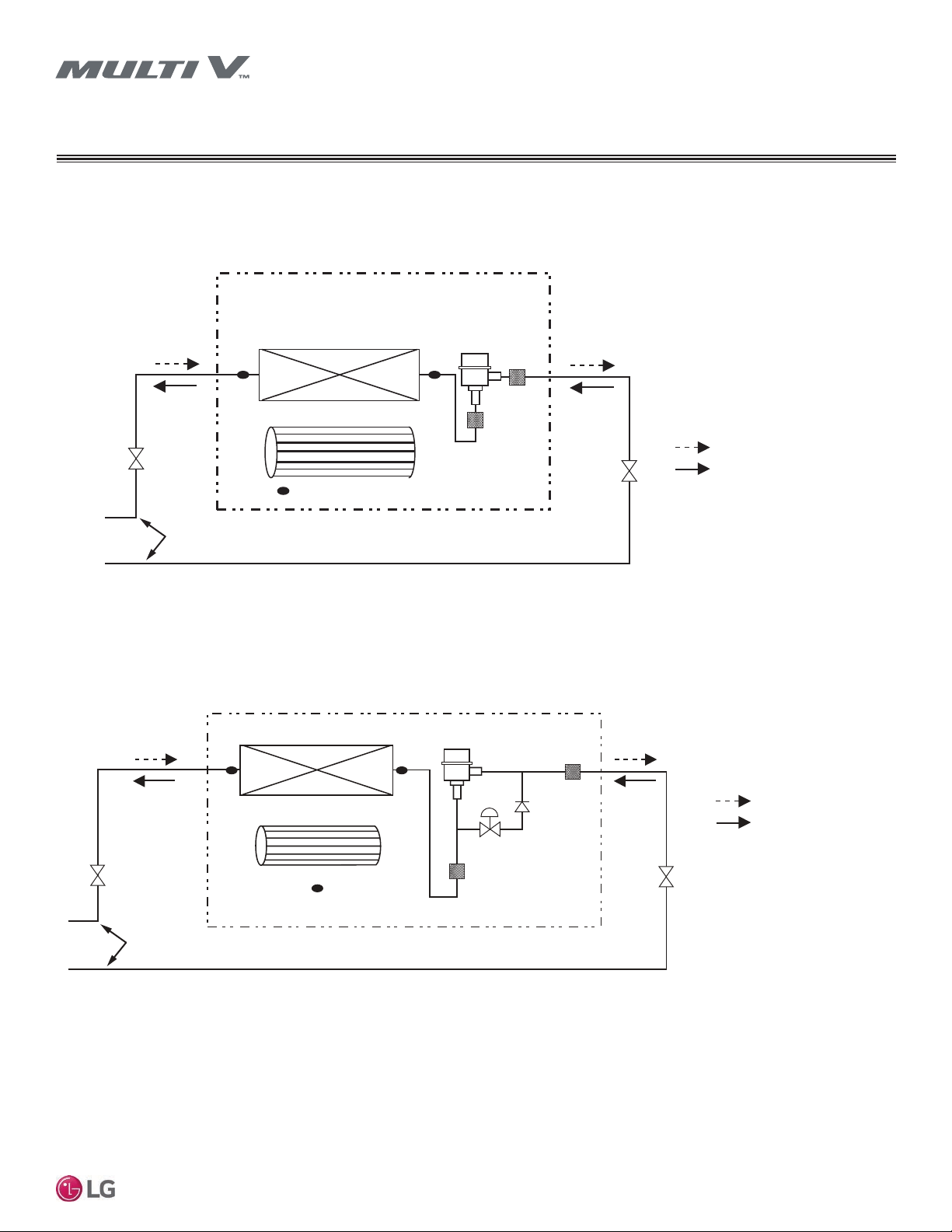
GENERAL DATA
Refrigerant Piping Diagrams
Figure 5: High-Static Ducted BG/BR/BH, Low-Static Ducted L1/L2L3/B3/B4, and Vertical Air Handler NJ/NK Refrigerant Piping Diagram
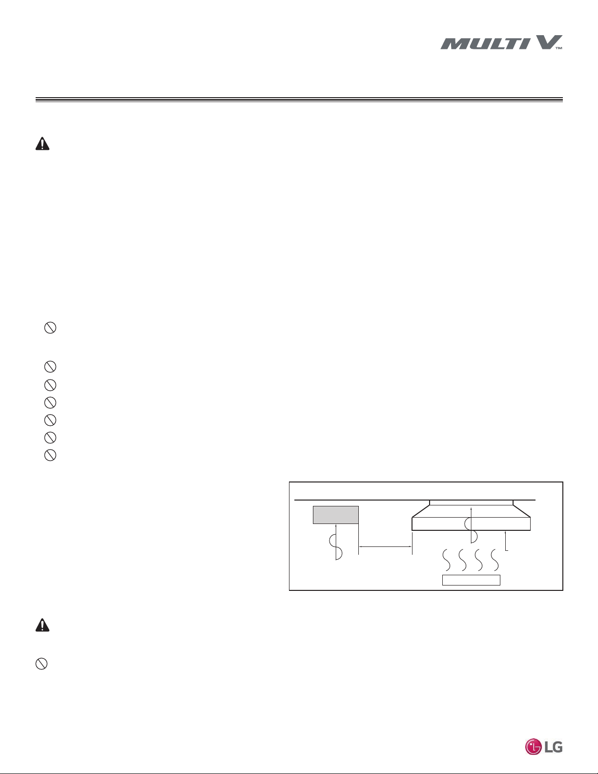
Figure 6: High-Static Ducted B8 Refrigerant Piping Diagram
Cooling
Heating
Th1 = Thermistor, Return Air
Th2 = Thermistor, Pipe In
Th3 = Thermistor, Pipe Out
EEV = Electronic Expansion Valve
Heat Exchanger
Sirocco Fan
Th3
Th2
EEV
Filter
Filter
Th1
lndoor Unit
Refrigerant Pipes
to Outdoor Unit
Flare Nut
Liquid Line
Vapor
Line
Flare Nut
Heat Exchanger
Sirocco Fan
TH3
TH1
TH2
lndoor unit
EEV
Filter
Check
Valve
Solenoid Valve
Filter
Cooling
Heating
Th1 = Thermistor, Return Air
Th2 = Thermistor, Pipe In
Th3 = Thermistor, Pipe Out
EEV = Electronic Expansion Valve
Refrigerant Pipes
to Outdoor Unit
Flare Nut
Liquid Line
Vapor
Line
Flare Nut
34
Multi V Ducted Indoor Units
Due to our policy of continuous product innovation, some specifications may change without notification.
©LG Electronics U.S.A., Inc., Englewood Cliffs, NJ. All rights reserved. “LG” is a registered trademark of LG Corp.
GENERAL INSTALLATION GUIDELINES
Unpack and Inspect for Freight Damage
CAUTION
Table 2 lists shipping and net weights. To help avoid personnel injury and unit damage, use at least two people when carrying a unit by hand.
Note:
Do not unpack the unit and remove protective materials until ready to install. Before opening the shipping container, check the container label-
ing to verify the unit received is the correct unit. Verify the unit capacity, type, and voltage. Refer to the Nomenclature chart on page 11. Before
unpacking, carefully move packaged unit to a work area near installation location. After opening, if unit is damaged, repack unit as it was shipped.
RETAIN ALL PACKING MATERIALS. In general, freight damage claims will be denied if the original packing materials are not retained for the claims
adjustor to inspect. File a freight claim and order a replacement unit.
1. Place the box on a solid surface right side up.
2. Cut the white reinforced nylon straps, open the top of the box, and fold back all four flaps.
Location Selection
DANGER
To avoid the possibility of re, do not install the unit in an area where combustible gas may generate, ow, stagnate, or leak. Failure to do so will
cause serious bodily injury or death. Before beginning installation, read the safety summary at the beginning of this manual.
Note:
Select a location for installing the wall-mounted indoor unit (IDU) that meets the following conditions:
• Where there is enough structural strength to bear the weight of the unit.
• Operating sound from the unit will not disturb occupants.
• Include enough space for service access.
• Include space for drainage to ensure condensate ows properly out of the unit when it is in cooling mode.
• Use a level indicator to ensure the unit is installed on a level plane.
• Include space for drainage to ensure condensate ows properly out of the unit when it is in cooling mode
Note:
The unit may be damaged, may malfunctioin, and/or will not operate as designed if installed in any of these conditions:
Do not install the unit near a heat or steam source (Figure 7) , or where considerable amounts of oil, iron powder, or flour are used.
These materials may generate condensate, cause a reduction in h eat exchanger efficiency, or malfuction of the condensate drain. If this is
a potential problem, install a ventillation fan large enough to vent out these materials
Do not install the unit where it will be subjected to direct thermal radiation from other heat sources.
Do not install the unit in an area where combustible gas may generate, flow, stagnate, or leak. There is the possibility of fire.
Do not install the unit in a location where acidic solution and spray (sulfur) are often used.
Do not use the unit in environments where oil, steam, or sulfuric gas are present.
Do not install additional ventilation products on the chassis of the unit.
Do not install the unit near high-frequency generator sources.
Installing in an Area Exposed to Unconditioned Air
In some installation applications, areas (floors, walls) in some
rooms may be exposed to unconditioned air. The room may be
above or next to an unheated garage or storeroom. To counter
this condition:
• Verify that carpet is or will be installed (carpet may increase
the temperature by three (3) degrees.
• Install radiant heat or another type of heating system to
the oor.
• Add insulatiion between the oor joists.
Figure 7: Installing Near a Heat or Steam Source
Install a ventilation fan
with sufficient capacity
Heat or steam source
Include enough
distance
Indoor Unit
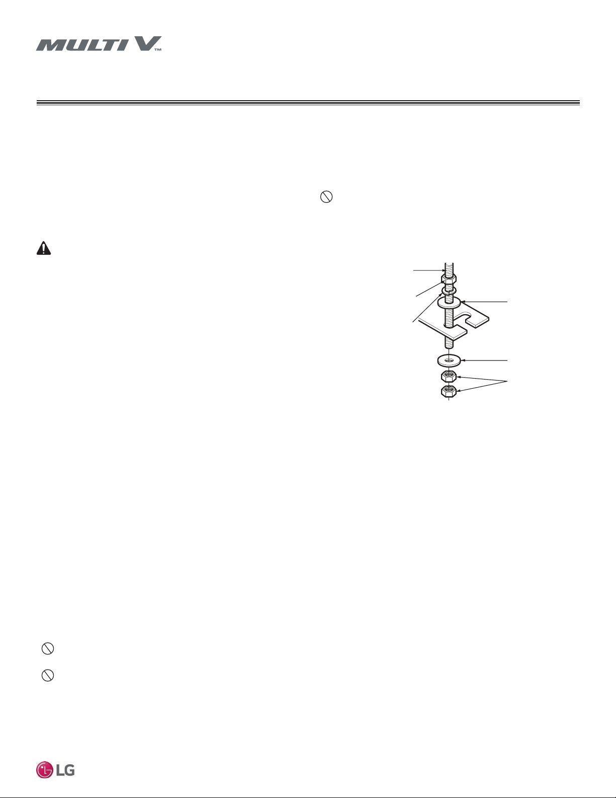
35
Installation Manual
Due to our policy of continuous product innovation, some specifications may change without notification.
©LG Electronics U.S.A., Inc., Englewood Cliffs, NJ. All rights reserved. “LG” is a registered trademark of LG Corp.
INSTALLATION
WARNING
Securely install threaded rod hangars (bolts) and hardware to
prevent the
chassis falling from its installation location.
• There is risk of personnel injury from falling equipment.
Installation work must be performed by trained personnel and in
accordance with all local or other applicable codes.
• There is risk of injury to personnel from incorrect installation.
Note:
• Ensure the unit is properly installed. Incorrectly installed units can
malfunction
resulting in degraded performance or an inoperative unit/system.
• Securely install threaded rod hangars (bolts) and hardware to prevent
the chassis falling from its installation location. There is risk of equip-
ment orproperty damage from falling equipment.
• Use a level indicator to ensure the chassis is installed on a level plane.
Roughing In the Indoor Unit
1. Determine the installation location. Ensure the location has enough space to allow necessary duct connections and maintenance access.
2. Securely install the four field-provided threaded rod hangars to the overhead support locations.
3. Hang the chassis from the four field-supplied threaded rod hangars. Refer to the threaded rod hangar details in Figure 8.
4. Use a level to ensure the chassis is level and securely tighten the mounting nuts.
5. If local code requires an auxiliary drain pan under the unit, install a field-provided auxiliary drain pan.
6. Connect ductwork to the unit as necessary.
Roughing-In Wall-Mounted Zone Controllers
Note:
• It may be necessary to use a handy box that is sized in metric units, depending on the controller model. Check with your LG representa-
tive to verify which size of handy box is needed for the zone controller in question.
• Use only LG-supplied communications cable. Using field-supplied cable may result in communications problems between the zone con-
troller and the indoor unit.
•
DO NOT cut the quick-connect plugs off or adjust the length of the cable.
• Keep the communications cable away from high voltage wires and electromagnetic field (EMF) producing equipment.
• Do not route power wiring and communications cables in the same conduit.
• Maintain the minimum distance required between the communications cable and power wiring. The minimum required space between the
two is dependent on the voltage of the power wiring. Refer to the appropriate Multi V Outdoor Unit Engineering Manual for
minimum distance specifications.
1. Proper indoor unit operation depends on the location of the room sensor. A good location will protect the zone controller from direct
sunlight and external local sources of water vapor, and heated or cooled air. If no mounting height was specified by the building de-
signer, place the handy box approximately fifty-five (55) inches above the finished floor.
Install Ducted IDU Chassis
Figure 8: Typical Threaded Rod Hanger and
Attaching Hardware
The following parts are field
supplied:
• Hanging bolt - W-3/8″ or 1/2″
• Nut - W-3/8″ or M10
• Spring washer - M10
Included with the indoor unit:
• Flat washer - M10
Flat washer for M10
(accessory)
Flat washer for M10
(accessory)
Hanging bolt
(W3/8 or M10)
Nut
(W3/8 or M10)
Nut
(W3/8 or M10)
Spring washer
(M10)
3. Remove the protective cardboard/Styrofoam
®
top sheet and place to the side.
4. The walls and top panels are not attached to the bottom of the box. Lift the carton by the flaps and remove the box walls and top.
5. Remove the moisture barrier plastic bonnet.
6. Check the unit nameplate data and model number. Verify the unit voltage, and capacities are correct before proceeding.
7. Locate and retain the piping/condensate accessory kit located in the bottom of the box under the refrigerant pipe stubs.
8. Using two people, carefully lift the unit and inspect for freight damage. DO NOT lift by the refrigerant piping or drain pipe stub. Lift by
the hangar brackets or chassis frame only. If damage is found, repack the unit as it was received in the original container.
9. If the unit is undamaged, remove and retain the installation manual. It is located under or on top of the unit.
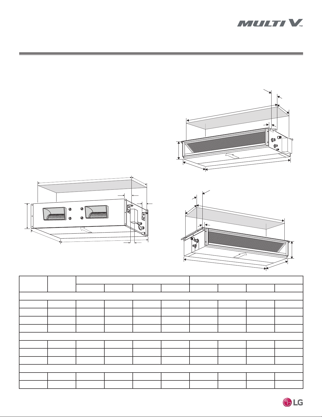
36
Multi V Ducted Indoor Units
Due to our policy of continuous product innovation, some specifications may change without notification.
©LG Electronics U.S.A., Inc., Englewood Cliffs, NJ. All rights reserved. “LG” is a registered trademark of LG Corp.
INSTALLATION
Indoor Unit Dimensions
2. Use only LG-provided cable to connect the zone controller. Pull LG communications cable between the zone controller handy box and the
indoor unit. A thirty-three (33) foot length of cable will be found with the wall-mounted zone controller.
3. Store a minimal amount of cable in the handy box. Any additional
cable should be coiled and stored near the indoor unit control
panel.
4. If additional cable is needed, order a thirty-three (33) foot LG
Wired Remote Group Control Extension cable (Model No. PZC-
WRC1).
5. If the cable between the zone controller and the indoor unit is too
long, do not cut the cable and shorten. Coil any spare
communications cable, tie-wrap it, and leave it next to the indoor
unit location.
6. Zone controller rough-in is complete.
Chassis
Code
Weight
(lbs.)
Major Dimensions (in.)
1
Mounting Dimensions (in.)
W D H L6 M1 M2 M3 M4
High-Static Ducted Indoor Units
BH 59 34-3/4 17-3/4 10-1/4 4-1/4 36-11/16 14 1 1-7/8
BG 84 46-1/2 17-3/4 11-3/4 4-1/4 48-1/2 14 1 1
BR 112 48-1/2 23-5/16 15 4-7/16 50-1/2 18-3/4 1 1
B8 192 61-5/8 27-1/8 18-1/8 4-11/16 63-7/8 22-7/8 1-3/16 1-3/16
Low-Static Ducted Indoor Units
L1 39 30-1/2 27-9/16 7-1/2 3 28-7/8 24-3/4 5/8 1-3/8
L2 51 38-3/8 27-9/16 7-1/2 3 36-3/4 24-3/4 5/8 1-3/8
L3 60 46-1/4 27-9/16 7-1/2 3 44-5/8 24-3/4 5/8 1-3/8
Low-Static Built-In Ducted Indoor Units
B3 46 32-5/8 22-5/8 7-1/2 1-7/16 33-7/16 15 5/8 3-11/16
B4 57 43-5/16 22-5/8 7-1/2 1-7/16 44-7/16 15 5/8 3-11/16
Table 14: Ducted Indoor Unit Dimensions and Weights.
Figure 9: High-Static Ducted Indoor Unit Dimensions.
M1
M2
M4
M3
L6
W
D
H
Airflow
1
Case dimensions exclude insulation. Add approximately 1/8" for factory-applied external insulation for each side. High-Static models are insulated on all sides. Low-Static models are
insulated on the bottom and end cold surfaces only between the fan discharge and midway to the rear of the unit.
Figure 10: Low-Static Ducted Indoor Unit Dimensions.
M1
M2
M4
M3
H
D
W
Airflow
M1
M2
M4
M3
H
D
W
Airflow
Figure 11: Low-Static Ducted Indoor Unit B3/B4 Dimensions.
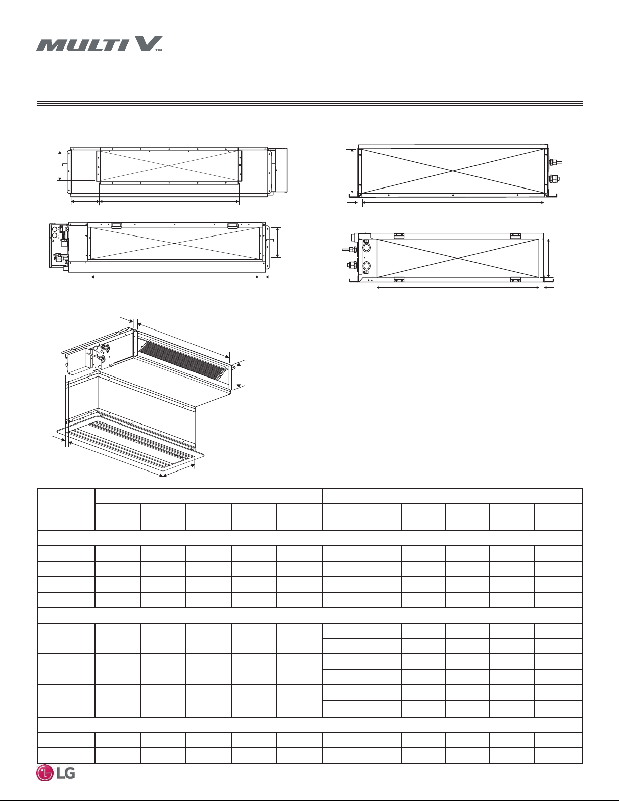
37
Installation Manual
Due to our policy of continuous product innovation, some specifications may change without notification.
©LG Electronics U.S.A., Inc., Englewood Cliffs, NJ. All rights reserved. “LG” is a registered trademark of LG Corp.
INSTALLATION
Duct Connection Dimensions
Chassis
Code
Supply Duct Connection Return Duct Connection
Type L1 L2 L3
Flange
Depth
Opening Location L5 L6 L7
Flange
Depth
High-Static Ducted Indoor Units
BH Flange 6-1/4 29-1/2 1-5/8 1-3/16 Rear 6-3/8 29-1/2 7/8 No Flange
BG Flange 7-5/16 32-11/16 6-7/8 1 Rear 7-7/8 41-1/8 1 No Flange
BR Flange 11-5/8 39-5/8 4-9/16 1 Rear 11-1/8 42-15/16 7/8 No Flange
B8 Flange 12-7/16 44-1/4 6-3/4 1 Rear 15-7/16 55 2 1-1/8
Low-Static Ducted Indoor Units
L1 Flange 5-7/8 26 13/16 5/8
Rear 6-1/8 26 3/4 No Flange
Bottom 6-1/16 26 3/4 No Flange
L2 Flange 5-7/8 33-13/16 13/16 5/8
Rear 6-1/8 33-11/16 3/4 No Flange
Bottom 6-1/16 33-13/16 3/4 No Flange
L3 Flange 5-7/8 41-3/4 13/16 5/8
Rear 6-1/8 41-11/16 3/4 No Flange
Bottom 6-1/16 41-11/16 3/4 No Flange
Low-Static Built-In Ducted Indoor Units
B3 Flange 6-7/16 31-5/16 1/2 3/4 Bottom 7 28-9/16 1-1/2 No Flange
B4 Flange 6-7/16 41-5/16 1/2 3/4 Bottom 7 39-9/16 1-1/2 No Flange
Table 15: Duct Connection Dimensions (in.).
Figure 12: High-Static Ducted (BH, BG, BR, B8) Indoor Unit Duct
Connection Dimensions.
Figure 13: Low-Static Ducted (L1/L2/L3) Indoor Unit Duct
Connection Dimensions.
Figure 14: Low-Static Built-In Ducted (B3, B4) Indoor Unit Duct Connection Dimensions.
L2
L7
L1
L5
L6
L3
L3
L1
L2
L5
L7
L6
L2
L3
L1
L6
L7
L5
Supply
Return
Supply
Return
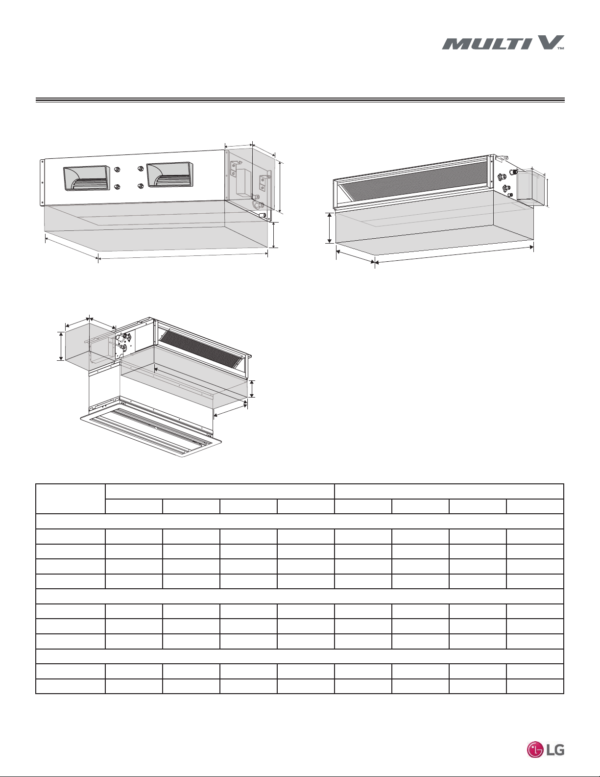
38
Multi V Ducted Indoor Units
Due to our policy of continuous product innovation, some specifications may change without notification.
©LG Electronics U.S.A., Inc., Englewood Cliffs, NJ. All rights reserved. “LG” is a registered trademark of LG Corp.
GENERAL INSTALLATION GUIDELINES
Maintenance Clearances
Chassis Code
Control Panel Access Major Maintenance Access
Location* C1 C2 C3 Location A1 A2 A3*
High-Static Ducted Indoor Units
BH Right End 12 12 10-1/2 Bottom 35 18 11
BG Right End 12 14 12 Bottom 47 18 12
BR Right End 12 14 15 Bottom 49 24 15
B8 Right End 12 14 18 Bottom 62 28 19
Low-Static Ducted Indoor Units
L1 Right End 10 12 8 Bottom 30 25 8
L2 Right End 10 12 8 Bottom 38 25 8
L3 Right End 10 12 8 Bottom 46 25 8
Low-Static Built-In Ducted Indoor Units
B3 Left End 10 12 8 Bottom 34 23 8
B4 Left End 10 12 8 Bottom 44 23 8
Table 16: Minimum Maintenance Clearances (in.).
C2
C1
C3
A3
A1
A2
C3
C1
C2
A1
A3
A2
Figure 15: High-Static Ducted (BG/BR/B8/BH) Indoor Unit
Maintenance Clearances.
Figure 16: Low-Static Ducted (L1/L2/L3) Indoor Unit
Maintenance Clearances.
Figure 17: Low-Static Built-In Ducted (B3, B4) Indoor Unit
Maintenance Clearances.
Note:
When space is available, best practice would be to
leave two (2) to three (3) inches on the end opposite the
control panel. Leave adequate room for visual inspection,
pipe installation, brazing, power wiring, control wiring,
and pipe insulating activities. Provide adequate access to
service nearby piping, drain lines, shutoff valves, etc., fol-
lowing the dimension guidelines listed in the table below.
*Does not apply when the ceiling surface below can be removed.
A1
A2
A3
C2
C1
C3
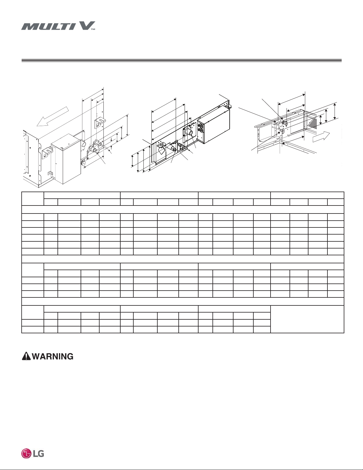
39
Installation Manual
Due to our policy of continuous product innovation, some specifications may change without notification.
©LG Electronics U.S.A., Inc., Englewood Cliffs, NJ. All rights reserved. “LG” is a registered trademark of LG Corp.
Refrigerant Safety
Verify the maximum refrigerant concentration in the space where the indoor unit will be mounted meets the concentration limit
allowed by ASHRAE Standards 15-2010 and 34-2010. There is danger of asphyxiation from oxygen displacement.
ASHRAE Standards 15-2010 and 34-2010 offer guidelines that address refrigerant safety and the maximum allowable concentration of
refrigerant in an occupied space. Refrigerant will dissipate into the atmosphere, but a certain volume of air is required for this to occur safely.
For R410A refrigerant, the maximum allowable concentration of refrigerant is twenty-six (26) lbs. per 1,000 cubic feet of an occupied space.
Buildings with twenty-four (24) hour occupancy allow half of that concentration.
1
ASHRAE Standards 15 and 34 assume that if a system develops a leak, its entire refrigerant charge will dump into the area where the leak
occurs. To meet ASHRAE Standards 15 and 34, calculate the refrigerant concentration that may occur in the smallest room volume on the
system, and compare the results to the maximum allowable concentration number.
1
Also consult state and local codes in regards to
refrigerant safety.
1
Information about ASHRAE Standard 15-2010 / 34-2010 and addenda current as of the date of this publication.
INSTALLATION
Piping Connections
Table 17: Ducted Indoor Unit Pipe Connections (in.).
Size /
Chassis
Liquid Line Vapor Line Condensate Pump Drain Gravity Drain (Plugged)
Dia.
1
Conn. L14 L17 Dia.
1
Conn. L13 L16 Dia.
1
Conn.
2
L11 L18 Dia.
3
Conn.
2
L12 L15
High-Static Ducted Indoor Units
7-18 BH 1/4 45° Flare 1-7/8 3-15/16 1/2 45° Flare 3-15/16 3-1/4 1.0 Plain 6-9/16 6-3/4 1.0"-14 MPT 1-1/8 6-9/16
24 BH 1/4 45° Flare 1-7/8 3-15/16 5/8 45° Flare 3-15/16 3-1/4 1.0 Plain 6-9/16 6-3/4 1.0"-14 MPT 1-1/8 6-9/16
07-42 BG 3/8 45° Flare 1-7/8 3-15/16 5/8 45° Flare 3-15/16 3-5/16 1.0 Plain 6-9/16 6-3/4 1.0"-14 MPT 6-9/16 1-1/8
28-54 BR 3/8 45° Flare 2-13/16 3-15/16 5/8 45° Flare 4-13/16 3-1/4 1.0 Plain 8-3/4 6-3/4 1.0"-14 MPT 8-3/4 1-1/4
36-76 B8 3/8 45° Flare 2-1/2 5-1/2 3/4 45° Flare 5-1/4 4-3/4 1.0 Plain 7-5/8 6-7/8 1.0"-14 MPT 7-5/8 1-1/4
96 B8 3/8 45° Flare 2-1/2 5-1/2 7/8 45° Flare 5-1/4 4-3/4 1.0 Plain 7-5/8 6-7/8 1.0"-14 MPT 7-5/8 1-1/4
Low-Static Convertible Ducted Indoor Units
Frame
Liquid Line Vapor Line Condensate Pump (Primary) Auxiliary Drain Connection
Dia.
1
Conn. L6 L9 Dia.
1
Conn. L7 L10 Dia.
1
Conn.
2
L5 L11 Dia.
1
Conn.
2
L20 L21
L1 1/4 45° Flare 3-7/8 7-1/4 1/2 45° Flare 3-1/2 4-1/2 1.0 Plain 2 11-1/2 1.0 Plain 6-3/8 9-3/4
L2 1/4 45° Flare 3-7/8 7-1/4 5/8 45° Flare 3-1/2 4-1/2 1.0 Plain 2 11-1/2 1.0 Plain 6-3/8 9-3/4
L3 3/8 45° Flare 3-7/8 7-1/4 5/8 45° Flare 3-1/2 4-1/2 1.0 Plain 2 11-1/2 1.0 Plain 6-3/8 9-3/4
Low-Static Bottom Ducted Indoor Units
Frame
Liquid Line Vapor Line Condensate Pump (Primary)
Dia.
1
Conn. L14 L17 Dia.
1
Conn. L15 L18 Dia.
1
Conn.
2
L13 L19
B3 1/4 45° Flare 9-7/16 2-9/16 1/2 45° Flare 8-1/2 4-15/16 1.0 Plain 10-7/8 5-1/16
B4 3/8 45° Flare 9-7/16 2-9/16 5/8 45° Flare 8-1/2 4-15/16 1.0 Plain 10-7/8 5-1/16
1
Inches I.D.
2
Plastic Resin
3
14 Threads Per Inch, Straight Thread
Figure 18: High-Static Ducted (BH/BG/BR/B8)
Indoor Unit Piping Connection Dimensions
.
Figure 19: Low-Static Convertible Ducted
(L1/L2/L3) Indoor Unit Piping Connection
Dimensions.
Condensate
Vapor Line
L14
L13
L15
L17
L18
L19
Liquid Line
Air
flow
L14
L13
L11
Condensate
Pump
(Primary)
Gravity Condensate
Vapor Line
Liquid Line
L12
L18
L17
L16
L15
Vapor Line
Airflo
w
Figure 20: Low-Static Ducted Built-In (B3/B4)
Indoor Unit Piping Connection Dimensions.
L5
L7
L20
L6
L10
L21
L9
L11
Condensate
Auxiliary Drain
Liquid Line
Vapor Line
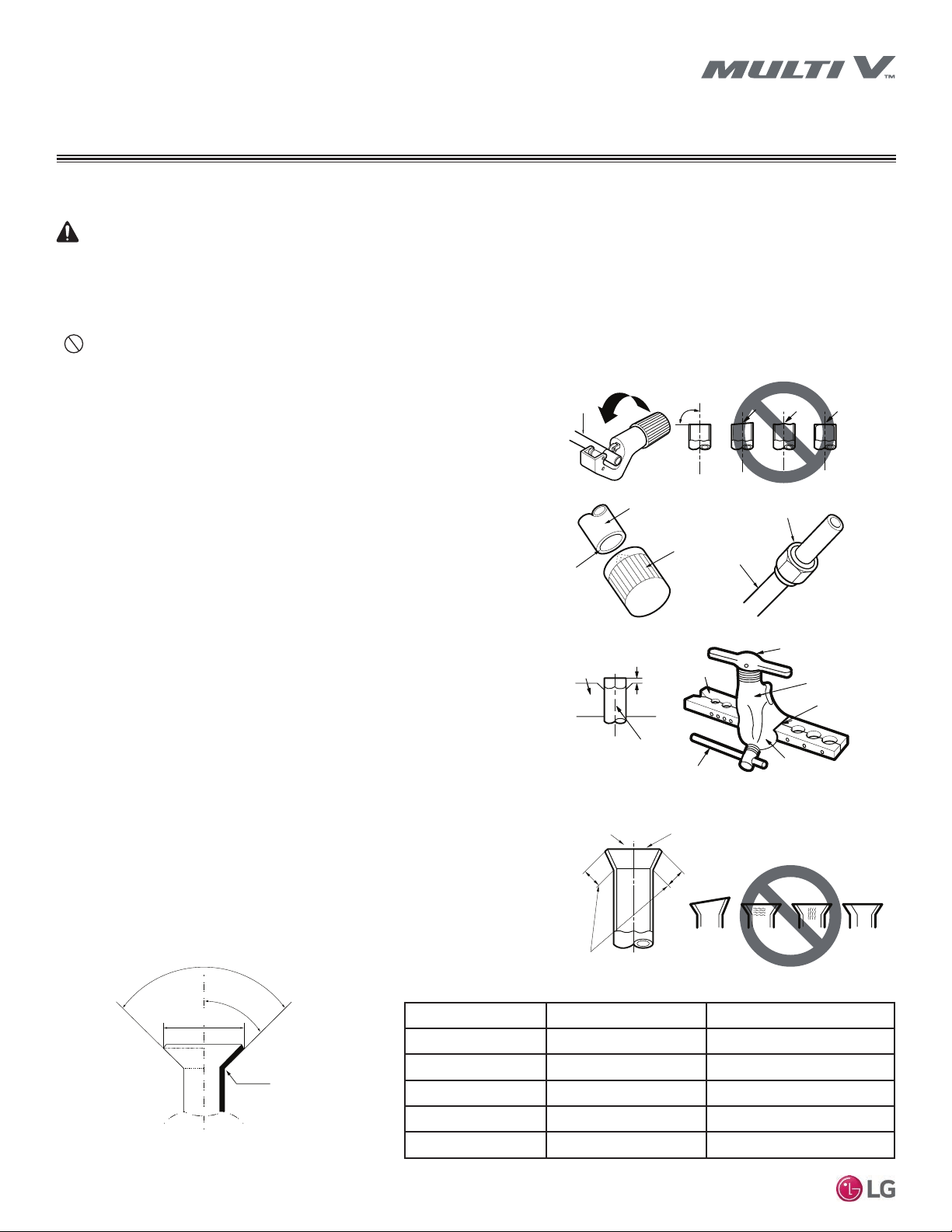
40
Multi V Ducted Indoor Units
Due to our policy of continuous product innovation, some specifications may change without notification.
©LG Electronics U.S.A., Inc., Englewood Cliffs, NJ. All rights reserved. “LG” is a registered trademark of LG Corp.
REFRIGERANT PIPING
Piping Preparation
WARNING
Do not braze in an enclosed location. Do not allow the refrigerant to
leak during brazing. Always test for gas leaks before and after brazing.
• If refrigerant combusts, it generates a toxic gas.
Note:
• Do not use kinked pipe.
Braze the pipe to the service valve pipe stub of the outdoor unit. After brazing,
check for refrigerant gas leaks. When selecting flare fittings, always use a 45°
fitting rated for high-pressure refrigerant R410A. Fittings must also comply with
local, state, and federal standards.
Creating a Flare Fitting
One of the main causes of refrigerant leaks is defective flared connections. Use
the following procedure to create flared connections.
1. Determine the installation location. Ensure the location has enough space to
allow necessary duct connections and maintenance access.
• Measure the distance between the indoor unit and the outdoor unit.
• Cut the pipes a little longer than measured distance.
2A. Remove the burrs.
• Completely remove all burrs from pipe ends.
• When removing burrs, point the end of the copper pipe down to avoid
introducing foreign materials into the pipe.
2B. Slide the are nut onto the copper tube.
3. Flare the pipe end.
• Use the proper size aring tool to nish ared connections as shown.
• ALWAYS create a 45° are when working with R410A.
4. Carefully inspect the ared pipe end.
• Compare the geometry with the gure to the right.
• If the are is defective, cut it off and re-do procedure.
• If are looks good, blow the pipe clean with dry nitrogen.
90°
Slanted Uneven Rough
Pipe
Reamer
Point
down
Flare nut
Copper
tube
Bar
Copper pipe
Clamp handle
Red arrow
Cone
Bar
Slanted
Smooth
Uneven
Thickness
1.
2A. 2B.
3.
4.
Handle
Incorrect Flare
Even Length
Cracked
Yoke
Inside is shiny with no scratches
Surface
Damaged
Copper
tube
90°
45°
“A”
R=0.4 – 0.8
Dimensions of the Flare.
Pipe Size (in. O.D.) Outside Diameter (mm) “A” Dimension (mm [in.])
1/4 6.35 ~ 9.1 (11/32 - 23/64)
3/8 9.52 ~ 13.2 (1/2 - 33/64)
1/2 12.7 ~ 16.6 (41/64 - 21/32)
5/8 15.88 ~ 19.7 (49/64 - 25/32)
3/4 19.05 ─
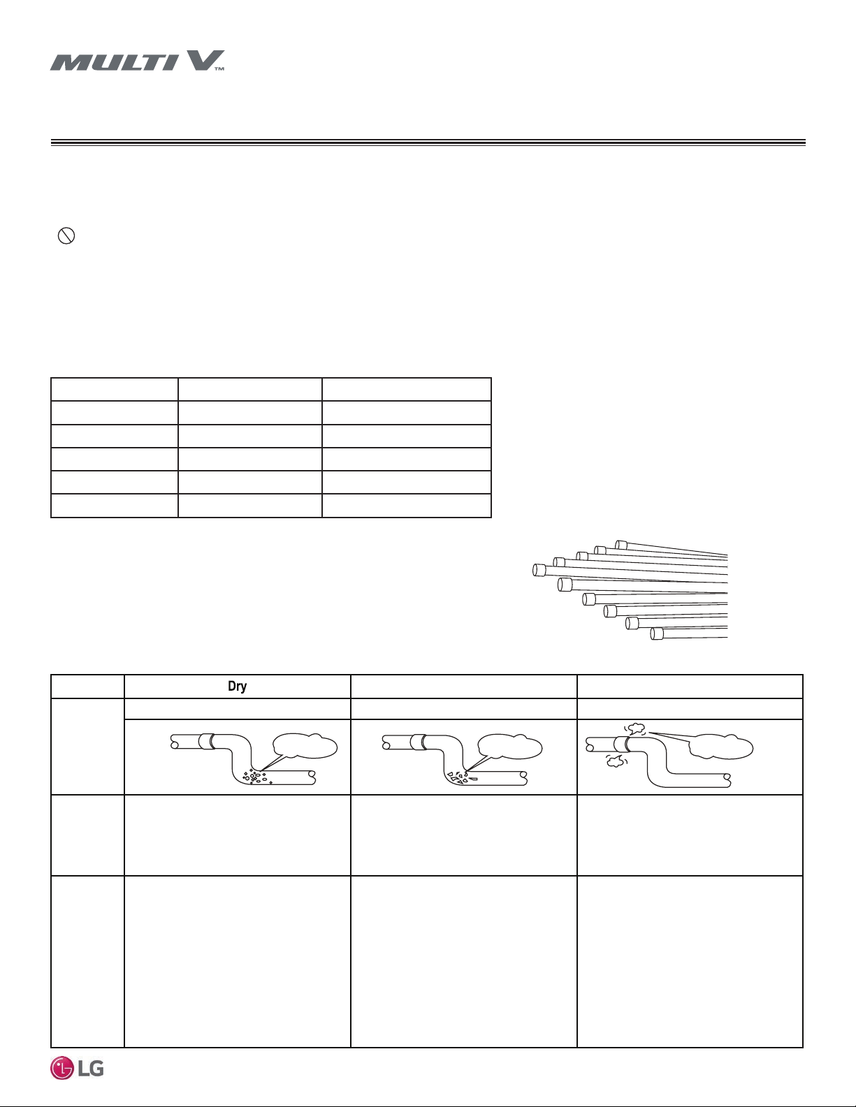
41
Installation Manual
Due to our policy of continuous product innovation, some specifications may change without notification.
©LG Electronics U.S.A., Inc., Englewood Cliffs, NJ. All rights reserved. “LG” is a registered trademark of LG Corp.
REFRIGERANT PIPING
Tightening Flare Nuts
1. When connecting the are nuts, coat the are (inside and outside) with polyvinyl ether (PVE) refrigeration oil only.
Note:
• Do not use polyolyester (POE) or any other type of mineral oil as a lubricant. These lubricants are not compat-
ible with PVE oil used in this system and create oil sludge leading to equipment damage and system malfunction..
2. Initially hand tighten the are nuts using three (3) or four (4) turns.
3. To nish tightening the are nuts, use both a torque wrench and a backup wrench.
4. After all the piping has been connected and the caps have been tightened, check for refrigerant gas leaks
Loosening Flare Nuts
Always use two (2) wrenches to loosen flare nuts.
Piping Materials and Handling
Pipes used for the refrigerant piping system must include the specified thickness,
and the interior must be clean. While handling and storing, do not bend or damage
the pipes, and take care not to contaminate the interior with dust, moisture, etc.
Keep refrigerant pipe dry, clean, and airtight.
Keep Pipes Capped While Storing.
Clean Airtight
No moisture should be inside the piping. No dust should be inside the piping. No leaks should occur.
Possible
Problems
- Significant hydrolysis of refrigerant oil.
- Refrigerant oil degradation.
- Poor insulation of the compressor.
- System does not operate properly.
- EEVs, capillary tubes are clogged.
- Refrigerant oil degradation.
- Poor insulation of the compressor.
- System does not operate properly.
- EEVs and capillary tubes become
clogged.
- Refrigerant gas leaks/shortages.
- Refrigerant oil degradation.
- Poor insulation of the compressor.
- System does not operate properly.
Solutions
- Remove moisture from the piping.
- Piping ends should remain capped until
connections are complete.
- Do not install piping on a rainy day.
- Connect piping properly at the unit’s side.
- Remove caps only after the piping is
cut, the burrs are removed, and after
passing the piping through the walls.
- Evacuate system to a minimum of 500
microns and insure the vacuum holds at
that level for 24 hours
- Remove dust from the piping.
- Piping ends should remain capped until
connections are complete.
- Connect piping properly at the side of
the unit.
- Remove caps only after the piping is cut
and burrs are removed.
- Retain the cap on the piping when
passing it through walls, etc.
- Test system for air tightness.
- Perform brazing procedures that comply
with all applicable standards.
- Perform flaring procedures that comply
with all applicable standards.
- Perform flanging procedures that
comply with all applicable standards.
- Ensure that refrigerant lines are pressure
tested to 550 psig.
Moisture
Dust
Leaks
Pipe Size (in. O.D.) Outside Diameter (mm) Tightening Torque (ft-lbs.)
1/4 6.35 13.0 - 18.0
3/8 9.52 24.6 - 30.4
1/2 12.7 39.8 - 47.7
5/8 15.88 45.4 - 59.3
3/4 19.05 71.5 - 87.5
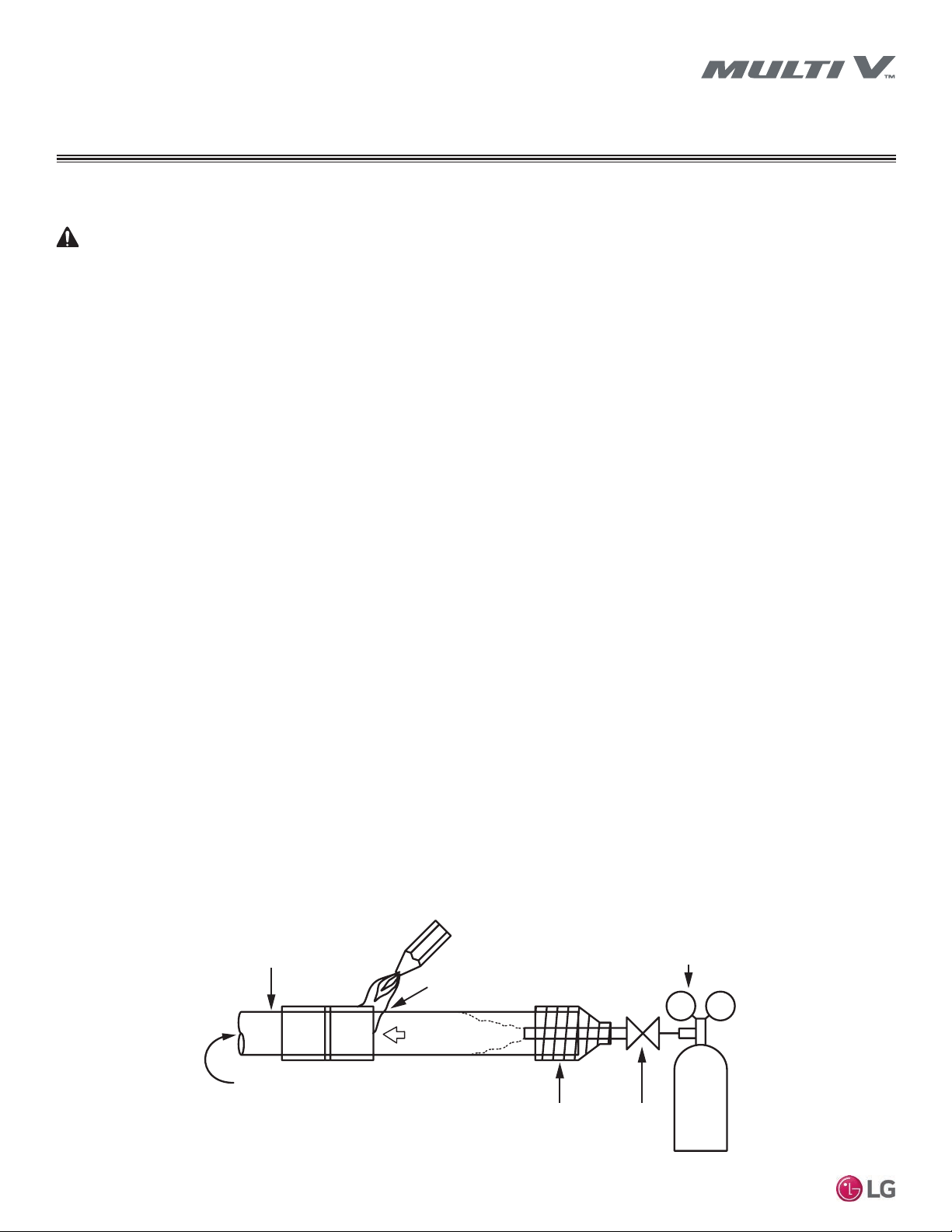
42
Multi V Ducted Indoor Units
Due to our policy of continuous product innovation, some specifications may change without notification.
©LG Electronics U.S.A., Inc., Englewood Cliffs, NJ. All rights reserved. “LG” is a registered trademark of LG Corp.
REFRIGERANT PIPING
Figure 21: Using Nitrogen Gas During Brazing
Refrigerant Safety
ASHRAE Standards 15-2010 and 34-2010 offer guidelines that address refrigerant safety and the maximum allowable concentration of
refrigerant in an occupied space. Refrigerant will dissipate into the atmosphere, but a certain volume of air is required for this to occur safely.
For R410A refrigerant, the maximum allowable concentration of refrigerant is twenty-six (26) lbs. per 1,000 cubic feet of an occupied space.
Buildings with twenty-four (24) hour occupancy allow half of that concentration.
1
ASHRAE Standards 15 and 34 assume that if a system develops a leak, its entire refrigerant charge will dump into the area where the leak
occurs. To meet ASHRAE Standards 15 and 34, calculate the refrigerant concentration that may occur in the smallest room volume on the
system, and compare the results to the maximum allowable concentration number.
1
Also consult state and local codes in regards to
refrigerant safety.
WARNING
Verify the maximum refrigerant concentration level in the space where the indoor unit will be mounted meets the concentration limit for the application.
There is risk of asphyxiation from oxygen depletion.
1
Information about ASHRAE Standard 15-2010/34-2010 and addenda current as of the date of this publication.
Auxiliary
Valve
Tape
(no air bubbles)
Do not block outlet side.
When pressure inside pipe
is above atmospheric pressure,
pinhole leaks can occur.
Refrigerant Pipe
Welding Point
Regulator
Nitrogen gas
3.0 psi or less
Nitrogen
Gas
Tank
Brazing
Note:
It is imperative to keep the piping system free of contaminants and debris such as copper burrs, slag, or carbon dust during installation.
1. All joints are brazed in the field. Multi V IV refrigeration system components contain very small capillary tubes, small orifices, electronic
expansion valves, oil separators, and heat exchangers that can easily become blocked. Proper system operation depends on the
installer using best practices and utmost care while assembling the piping system.
• Store pipe stock in a dry place and keep stored pipe capped and clean.
• Purge all pipe sections clean with dry nitrogen prior to assembly.
2. Proper system operation depends on the installer using best practices and the utmost care while assembling the piping system.
• Use adapters to assemble different sizes of pipe.
• Always use a non-oxidizing material for brazing. Do not use ux, soft solder, or anti-oxidant agents. If the proper material is not used,
oxidized lm may accumulate and clog or damage the compressors. Flux can harm the copper piping or refrigerant oil.
• Use a tubing cutter; do not use a saw to cut pipe. De-bur and clean all cuts before assembly.
3. Brazing joints:
• Use a dry nitrogen purge operating at a minimum pressure of three (3) psig and maintain a steady ow.
• Use a 15% silver phosphorous copper brazing alloy to avoid overheating and produce good ow.
• Protect isolation valves, electronic expansion valves, and other heat-sensitive control components from excessive heat with a wet rag or
heat barrier spray.
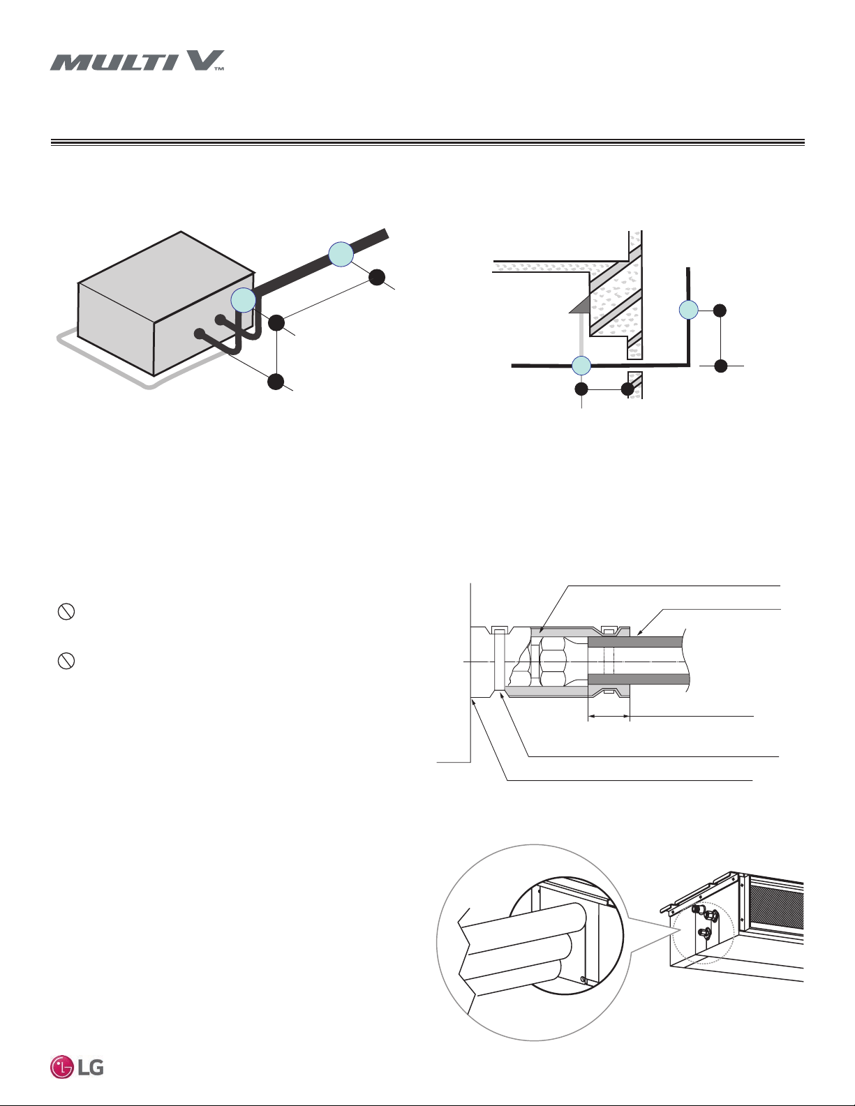
43
Installation Manual
Due to our policy of continuous product innovation, some specifications may change without notification.
©LG Electronics U.S.A., Inc., Englewood Cliffs, NJ. All rights reserved. “LG” is a registered trademark of LG Corp.
REFRIGERANT PIPING
A properly installed pipe system will have sufficient support so that pipes will not sag during the life of the system. As necessary, place supports
closer for segments where potential sagging could occur. Maximum spacing of pipe supports must meet local codes.
Refrigerant Pipe Connections
Indoor units come with flare type connections. It is the installer’s option to use the flare fittings provided or braze the indoor unit to the
refrigerant piping system.
Flare Fittings
• All unit are ttings are 45° and rate for high-pressure R410A refrigerant.
• Properly form all are ttings using best practices.
• Place a drop of PVE oil on the outside of the are tting before
tightening.
Note:
Multi V refrigeration system components contain very small capillary
tubes, small orices, electronic expansion valves, oil separators, and
heat exchangers that can easily become blocked.
Max. 12"
~ 12" – 19"
A
B
A + B ~ 12" – 19"
Figure 22: Pipe Support at Indoor Unit. Figure 23: Typical Pipe Support Location—Change in Pipe Direction.
Note:
• Do not use any other type of oil (including traditional POE refrig-
eration oil) as a lubricant. Failure to follow this procedure may lead to
restrictions in the refrigeration components.
•
Do not over-tighten flare nuts. Excessive tightening will cause
fittings to crack.
Insulate Refrigerant Pipes
Sufficiently insulate all cold surfaces to prevent moisture forming. All
pipes must be insulated and each pipe must be separately wrapped.
Refer to Figure 24 and Figure 25. Use field-provided one-half (1/2)
inch thick (or thicker) closed-cell insulation. The thickness may need
to be increased based on ambient conditions and local codes.
Wrap all refrigerant and condensate piping including field-provided
isolation ball valves and flexible pipe connection kits provided by LG.
Glue all insulation joints with no air gaps between insulation seg-
ments, and between insulation segments and the unit case. Ensure
insulation material fits snugly against the refrigeration pipe with no air
space between the pipe surface and the surrounding insulation.
Protect insulation inside hangers and supports with a second insula-
tion layer. Ensure insulation on all pipe passing through pipe hangers,
inside conduit, and/or sleeves is not compressed.
Figure 24: Typical Refrigerant Line Flare Fitting Insulation Detail
No Clearance
Overlap Insulation Where the
Port and the Piping Meet
Insulation for Indoor Unit Port
(Field Supplied)
Insulation for Refrigerant
Piping (Field Supplied)
Insulation Clip (Field Supplied)
Figure 25: No Air Gap in Pipe Insulation to Indoor Unit Frame.
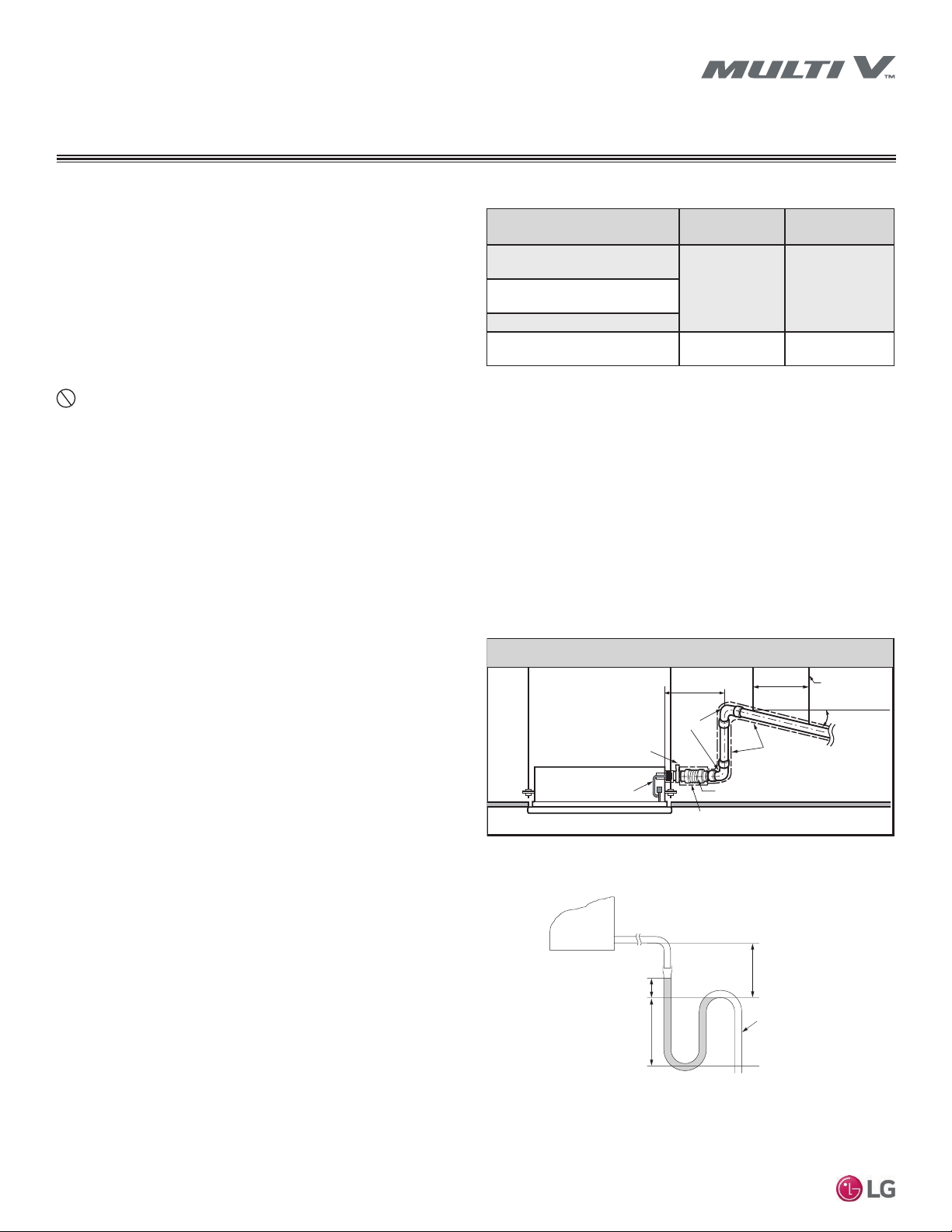
44
Multi V Ducted Indoor Units
Due to our policy of continuous product innovation, some specifications may change without notification.
©LG Electronics U.S.A., Inc., Englewood Cliffs, NJ. All rights reserved. “LG” is a registered trademark of LG Corp.
Condensate Pump Connection
All ducted units have a condensate pump except the vertical air handler unit. Note the following when connecting the condensate pipe to the unit.
• Indoor units DO NOT come with check valves or a backow prevention device. If check valves are needed, they must be eld supplied.
• The maximum lift of all condensate pumps is 27 in.-wg.
• Measure lift distance from the bottom surface of the indoor unit, NOT from the condensate pipe connection.
• Slope all horizontal condensate pipe segments a minimum of 1/4 inch per foot away from the indoor unit.
Ducted Unit Drain Information
When the bottom surface of the indoor unit is at an elevation below
the receiving building drain line connection, install an inverted trap at
the top of the condensate pump discharge riser before connection to
the building drain pipe.
When the receiving drain line is mounted horizontal, connect the
inverted trap to the top half of the pipe. The connection point of the
inverted trap to the building drain pipe should always be to the top
half of the pipe and should never be over 45° either side of the upper
most point of the horizontal building drain line.
If connecting to a vertical drain line or plumbing system vent line,
connect the IDU condensate pump discharge line using a Y-45 fitting
with the double end of the Y-45 fitting facing up. When connecting to
a vertical drain line include an inverted trap at the top of the IDU con-
densate pump discharge riser before connection to the Y-45 fitting.
Gravity Condensate Pipe Connection
High-static indoor units (BH/BG/BR/B8) have an auxiliary gravity
condensate drain connection just below the condensate pump pipe
connection on the control panel end of the unit. This connection may
be used instead of using the condensate pump.
• Verify the unit is installed with a slight cant toward the gravity
drain connection.
• Remove the rubber plug before connecting the condensate line
to the indoor unit.
• The gravity condensate line must be equipped with a conden-
sate trap for proper condensate ow. Refer to Figure 26 for trap
details.
• All horizontal segments of condensate pipe should be sloped a
minimum of 1/4 inch per foot away from the indoor unit.
• Use materials acceptable by local code.
CONDENSATE PIPING
All ducted indoor units except the vertical air handler have a factory-
mounted condensate pump that runs continuously while the unit is in
cooling mode. The pump has an internal high-level float switch that
stops the unit if the water level in the pan rises too high.
All ducted indoor units have a flexible drain hose kit and one or two
clamps. The hose can be used to connect the condensate pipe to
the condensate pump connection. On high-static units, there is the
option to directly connect a one (1) inch FPT fitting to the drain pan’s
gravity drain connection.
Note:
When making condensate pipe connections, be careful not to exert lateral force on the drain nipple. Internal damage
may occur. Refer to Table 17 for condensate pipe connection sizes.
Indoor Unit Drain Type
Drain Pipe Dia.
(ID, in.)
BH, BG, BR, B8 Frame
High Static Ducted
27 in. Lift
Drain Pump,
Factory Installed
Ø1L1, L2, L3 Frame
Low Static Ducted
B3, B4 Frame Built In Ducted
NJ, NK Frame Vertical/Horizontal
Air Handler Unit
Gravity Ø1
Table 18: Indoor Unit Drainage Specications.
1/50~1/100
slope
Hanger distance
3.3~4.9 feet
Hanger Bracket
Flexible drain hose
Insulation
Metal
clamp
Max.
11-13/16 inches
PVC Piping
PVC Elbow
Drain pump
Figure 26: High Static, Low Static, Built In Ducted Indoor Unit Drain
Pump to Drain Piping System
Figure 27: Gravity Condensate Trap..
U-Trap
B
C
A
Where:
A = 2-1/2"
B ≥ 2 x C
C ≤ 2 x External Static Pressure (in.-wg)
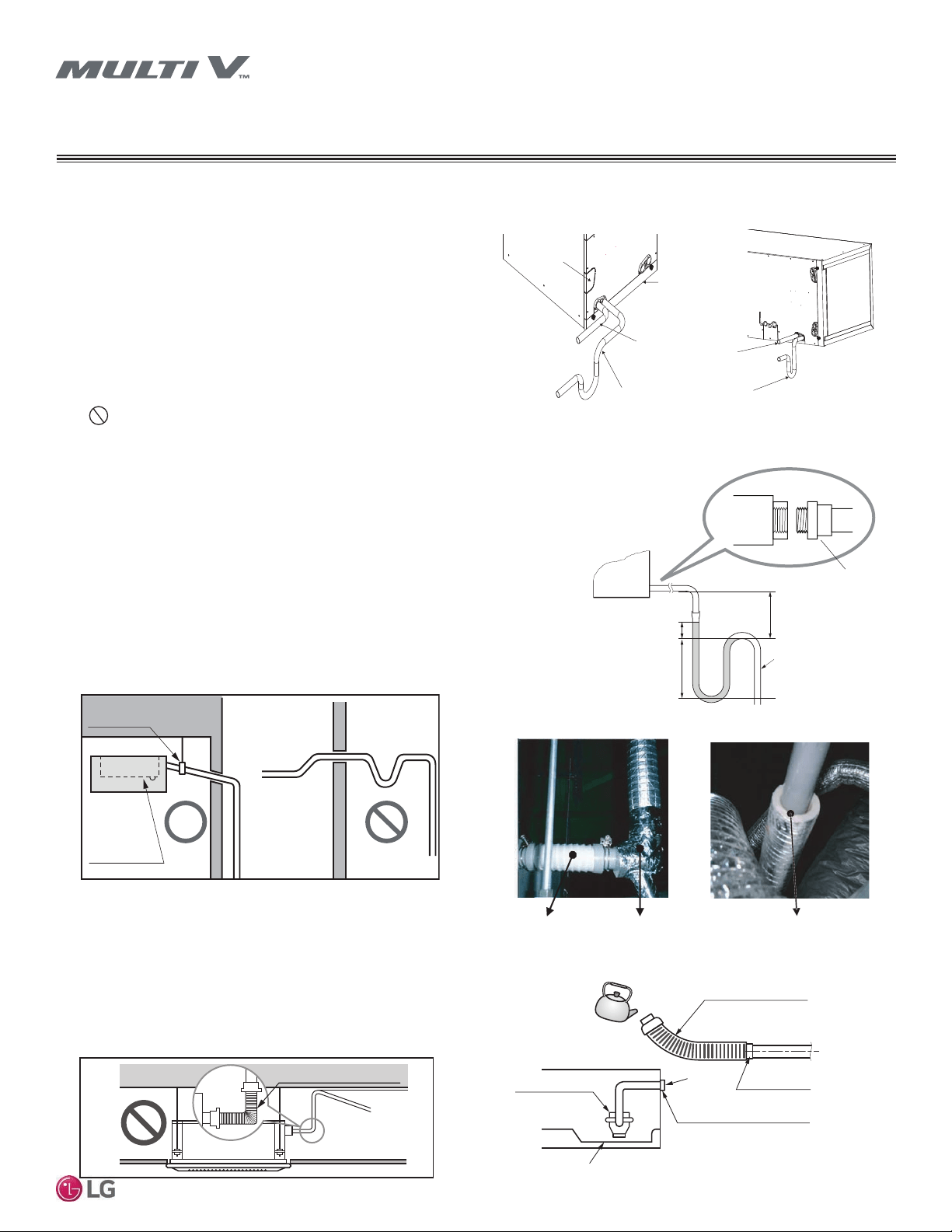
45
Installation Manual
Due to our policy of continuous product innovation, some specifications may change without notification.
©LG Electronics U.S.A., Inc., Englewood Cliffs, NJ. All rights reserved. “LG” is a registered trademark of LG Corp.
CONDENSATE PIPING
Install the Condensation Drain Pipe
• Drain piping must slope down or ow may reverse back to unit.
• During drain piping connection, be careful not to exert extra force
on the drain port on the indoor unit.
• Refer to Table 17 for drain pipe sizing.
• Use polyvinyl chloride pipe.
• Install insulation on the drain piping.
• Use polyethylene foam greater than 5/16 inch thick for insulation.
1. Refer to Figure 30 and plan the drain pipe routing so that the pipe
will slope downward from the indoor unit to its end drain location.
2. Connect the provided flexible drain pipe to the main drain pipe.
3. Pour water into the flexible pipe as shown in Figure 33 to test for
leaks. Repair leaks if necessary.
4. Route the flexible drain pipe to the indoor unit and connect the
flexible drain pipe to the drain port of the indoor unit.
5. Install field-supplied thermal insulation on the flexible drain pipe
and position snugly against indoor unit.
Figure 28: Vertical / Horizontal Air Handler Unit Drain Piping System.
D
r
a
i
n
f
o
r
U
p
f
l
o
w
I
n
s
t
a
l
l
a
t
i
o
n
s
H
o
r
i
z
o
n
t
a
l
-
L
e
f
t
D
r
a
i
n
A
c
c
e
s
s
H
o
l
e
A
i
r
F
i
l
t
e
r
C
o
v
e
r
M
a
i
n
d
r
a
i
n
a
l
o
n
g
w
i
t
h
s
u
i
t
a
b
l
e
t
r
a
p
.
(
A
f
i
e
l
d
-
s
u
p
p
l
i
e
d
t
r
a
p
w
i
t
h
s
u
f
f
i
c
i
e
n
t
d
e
p
t
h
c
a
n
b
e
u
s
e
d
.
S
t
a
n
d
a
r
d
-
s
i
z
e
d
t
r
a
p
s
a
r
e
n
o
t
s
u
f
f
i
c
i
e
n
t
.
R
e
f
e
r
t
o
t
h
e
U
-
T
r
a
p
S
p
e
c
i
f
i
c
a
t
i
o
n
s
f
i
g
u
r
e
f
o
r
t
h
e
r
e
c
o
m
m
e
n
d
e
d
c
o
n
d
e
n
s
a
t
e
t
r
a
p
.
)
S
u
p
p
l
e
m
e
n
t
a
r
y
d
r
a
i
n
w
i
t
h
p
r
o
p
e
r
t
r
a
p
.
(
F
i
e
l
d
-
s
u
p
p
l
i
e
d
k
i
t
c
a
n
b
e
u
s
e
d
.
)
D
r
a
i
n
f
o
r
H
o
r
i
z
o
n
t
a
l
-
L
e
f
t
I
n
s
t
a
l
l
a
t
i
o
n
s
Figure 29: Vertical / Horizontal Air Handler Unit U-Trap Specications.
U-Trap
B
C
A ≥
2-9/16 inch
B ≥ 2C
C ≥ 2 x SP
SP = External Pressure
(in. WG)
Ex) External Pressure
= 0.4 in. WG
A ≥ 2-9/16 inches
B ≥ 1-7/12 inches
C ≥ 13/16 inches
A
Applied U-Trap Dimensions
• Install the U-Trap to prevent leaks
caused by blocking the intake air filter.
3/4 inch
connector
Vertical/Horizontal Air Handler Unit Drain Information
Note:
Install a eld-supplied external condensate pan underneath the entire
vertical air handler unit to avoid damage due to condensate overow.
Vertical / Horizontal Air Handler units have a gravity drain.
• Avoid blocking lter access panel when connecting drain lines.
• An additional external condensate line should run from the unit
into the pan.
• The entire condensate line should be drained from the external
condensate pan.
• Point the drain hose downward for easy drain ow.
•
Do not use pipe joint connection or PVC/CPVC for the unit
drain line connection. Use Teon® tape.
Maintenance
drain port
Upward
routing
not allowed
Pipe clamp
Indoor unit
Figure 30: Drain Piping Slope.
Insulation
Requir ed
Insulation
Not Required
Properly Fitting Insulation
Figure 31: Properly Insulating the Drainage Piping.
Pour water to
test for proper
drainage and
no leaks
Drain Pump
Drain pan
Flexible drain hose
Main drain pipe
Glue the joint
Drain
port
Drain hose clip (provided)
Flexible drain hose
Figure 32: Do Not Sharply Bend Drain Pipe.
Figure 33: Testing the Drain Pipe.

46
Multi V Ducted Indoor Units
Due to our policy of continuous product innovation, some specifications may change without notification.
©LG Electronics U.S.A., Inc., Englewood Cliffs, NJ. All rights reserved. “LG” is a registered trademark of LG Corp.
POWER AND CONTROL WIRING
Overview
DANGER
High voltage electricity is required to operate this system. Adhere to the National Electrical Codes and these
instructions when wiring.
Improper connections and inadequate grounding can cause accidental injury or death.
Always ground the unit following local, state, and National Electrical Codes.
Improper connections and inadequate grounding can cause accidental injury or death.
Properly size all circuit breakers or fuses.
There is risk of re, electric shock, explosion, physical injury or death.
WARNING
The information contained in this manual is intended for use by a trained electrician familiar with applicable
local codes and the U.S. National Electric Code (NEC), and who is equipped with the proper tools and test
instruments.
Failure to carefully read and follow all instructions in this manual can result in personal injury or death.
Connect the indoor unit input power cable but do not apply power to the indoor unit until authorized to do so
by the system commissioning agent.
Inappropriate power connection can result in personal injury or death.
Ensure the unit is connected to a dedicated power source that provides adequate power.
If the power source capacity is inadequate or the electric work is not performed properly, it may result in re, electric shock, physical
injury or death.
Refer to local, state, and federal codes, and use power wires of sufcient current capacity and rating.
Wires that are too small may generate heat and cause a re, resulting in physical injury or death.
Secure all eld wiring connections with appropriate wire strain relief.
Improperly securing wires will create undue stress on equipment power lugs. Inadequate connections may generate heat, cause
a re and physical injury or death.
Properly tighten all power connections.
Loose wiring may overheat at connection points, causing a re, physical injury or death.
Note:
Connect the indoor unit input power cable but do not apply power to the indoor unit until authorized to do so
by the system commissioning agent.
Inappropriate power connection can result in equipment damage and will void the LG limited liability warranty.
Do not cut, lengthen or shorten the communications and power cable between a zone controller or dry contact
unit and its connected indoor unit. Do not install the zone controller or dry contact unit in a location where the
communications and power cable cannot be safely and easily connected between the two units. Do not allow
strain on this cable.
Poor cable connections can cause equipment malfunction.
The information contained in this manual is intended for use by an industry-qualied, experienced, trained
electrician familiar with applicable local codes and the U.S. National Electric Code (NEC), and who is
equipped with the proper tools and test instruments.
Failure to carefully read and follow all instructions in this manual can result in equipment malfunction or property damage and will
void the LG limited liability warranty.
Connecting Power and Control Wiring
Indoor unit installation best practices are to connect control wiring (low voltage) and then connect power wiring (high voltage).
Do not apply power to the indoor unit or any Multi V system component until authorized to do so by the system commissioning
agent.
47
Installation Manual
Due to our policy of continuous product innovation, some specifications may change without notification.
©LG Electronics U.S.A., Inc., Englewood Cliffs, NJ. All rights reserved. “LG” is a registered trademark of LG Corp.
WIRING
Indoor Unit Communication Cable Connections
Note:
Failure to follow any of these power and communications wiring guidelines or instructions will likely cause
communications errors and unit malfunction.
Polarity matters. When connecting the communications cable conductors at each Multi V system compo-
nent, be careful the conductor connected to the IDU(A) terminal on the outdoor unit is connected to the
A/3(A) terminal at each indoor unit. The conductor connected to the IDU(B) terminal on the outdoor unit
must be connected to the B/4(B) terminals at each indoor unit. Cross connecting the A/3(A) and B/4(B)
terminals will cause communications errors and system malfunction.
Don’ts
• Never use wire caps and never splice communications cables.
• Star and Wye communications cable congurations are not acceptable.
• Never connect zone controllers or other central control products such as AC Smart, PDI, or LG building
management system gateway products to the IDU/ODU communications cable.
• Keep communications cables away from line voltage wiring, lighting ballasts, and other devices emit-
ting EMF energy. Maintain a minimum of two (2) inches between line voltage wires and communica-
tions or zone controller cables.
• Field provide a minimum of 18-2 AWG, stranded and shielded, PVC or vinyl jacket communications
wiring between the indoor units, heat recovery boxes (if applicable), and outdoor units.
• The outdoor/indoor unit communications cable must be run between components in a daisy chain
conguration. Star or wye congurations are not allowed.
• Refer to the wiring connection diagrams for the appropriate unit (Figure 34 through Figure 40)
Connect the communications cables to the A/3(A) and B/4(B) terminals at indoor units and/or heat
recovery units. Maintain polarity throughout the communications bus. Be sure A/3(A) terminals are
connected to A/3(A) terminals and B/4(B) terminals are connected to B/4(B) terminals.
• Ground the shield of the communications cable at one end only, at the master outdoor unit.
Note:
The minimum distance required between power wires and the communications cable is voltage/amperage
dependent and in cases where either are relatively high the minimum distance may be more than two (2)
inches. Refer to the appropriate LG Multi V Outdoor Unit Engineering Manual on www.lg-vrf.com for detailed
information.
Communication Cable Connection
Note:
When connecting the communications bus between the outdoor unit, indoor unit(s), and heat recovery unit(s),
it does not matter what physical path or route the wire takes. The installer may use discretion when choosing
the order the components are connected to the communications bus, but must maintain the daisy chain and
polarity conguration.
1. If not already done so, read Connecting Power and Control Wiring on the previous page.
2. Remove a knock-out plug from the control box. Remember the communications cable and the power
cable must enter the control box through different knockouts.
3. Field-install a plastic or rubber grommet in the knockout hole to prevent wire chafng.
4. If using conduit, connect the conduit to the control box using field-provided fittings and industry best-
practice procedures.
5. Provide at least three (3) to four (4) inches of slack cable at each indoor unit.
6. Secure the communications cable to the inside surface of the control box using a field provide nylon
wire clamp.
7. Strip approximately half of an inch of insulation from each communications cable conductor. At each
indoor unit, insert the conductors under the terminal screw.
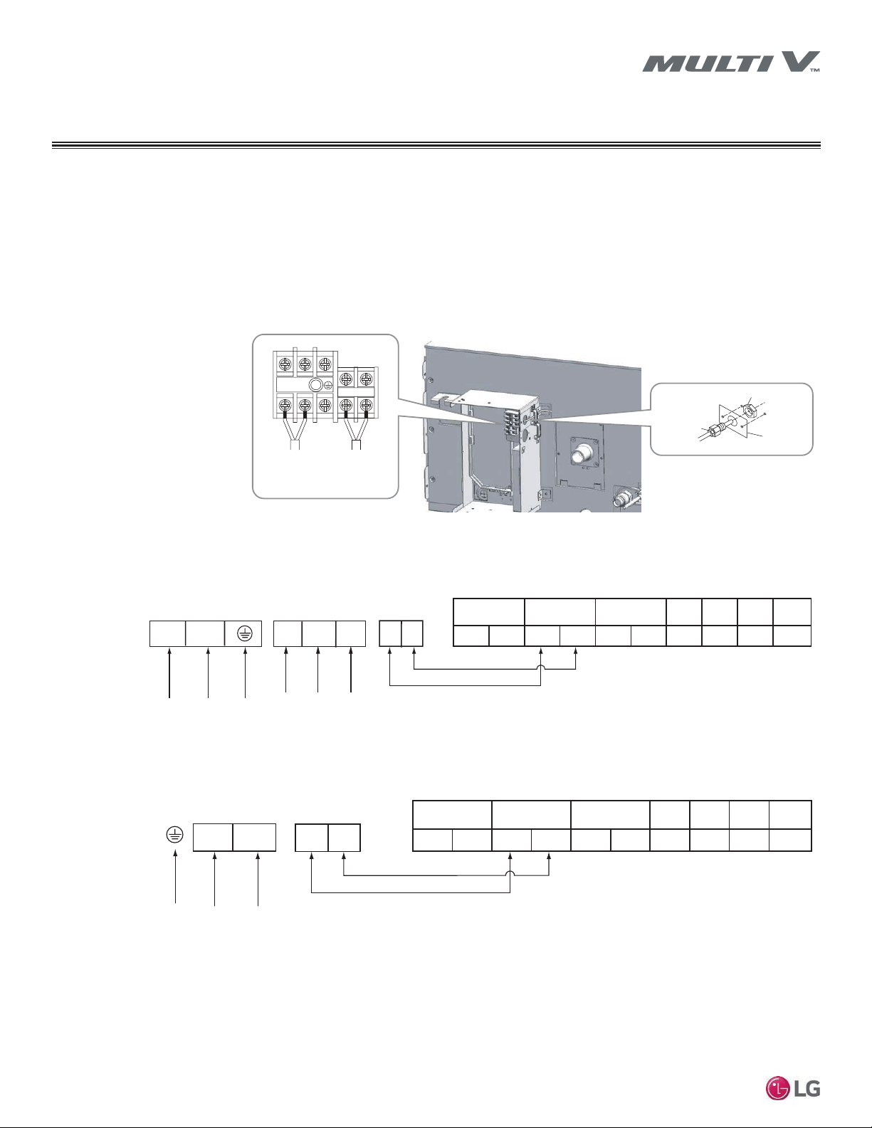
48
Multi V Ducted Indoor Units
Due to our policy of continuous product innovation, some specifications may change without notification.
©LG Electronics U.S.A., Inc., Englewood Cliffs, NJ. All rights reserved. “LG” is a registered trademark of LG Corp.
WIRING
Indoor Unit Communications Cable Connections
8. Securely tighten the terminal screws to prevent the communica-
tions conductors from coming loose from the terminal block.
9. Secure the communications cable in appropriate locations
outside the indoor unit to prevent damage to the cable or injury to
maintenance personnel.
Figure 34: Location of Power Wiring and Communications Cable Terminals in the High Static
and Low Static Ducted Indoor Units
Lock nut
Conduit
mounting
plate
Conduit
L(L1)N(L2)
A B
Power Supply
High Voltage
(208/230V)
Communications
BG, BR, B8 Frame Terminals
Indoor Unit Terminal Block
L(L1) N(L2)
A------ABB
GND 12V
DRY2DRY1
INTERNETIDUSODU
Outdoor Unit Terminal Block
Power Input
208-230V /
60 Hz / 1 Phase
Ground
YL RD
A B
BK
Wired Controller
Figure 35: Terminal Block in the High Static (BH, BG, BR, B8 Frame) Ducted Indoor Units
Indoor Unit Terminal Block
L(L1) N(L2)
A------ABB
GND 12V
DRY2DRY1
INTERNETIDUSODU
Outdoor Unit Terminal Block
Power Input
208-230V /
60 Hz / 1 Phase
3(A) 4(B)
Ground
Figure 36: Terminal Block in the Low Static (L1, L2, L2 Frame) Ducted Indoor Units
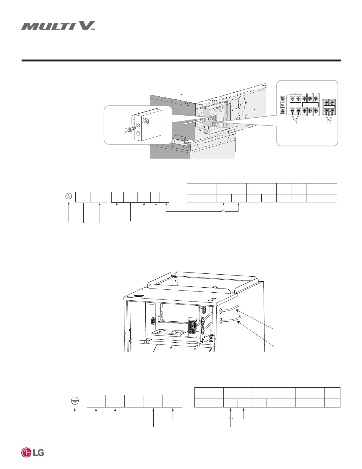
49
Installation Manual
Due to our policy of continuous product innovation, some specifications may change without notification.
©LG Electronics U.S.A., Inc., Englewood Cliffs, NJ. All rights reserved. “LG” is a registered trademark of LG Corp.
WIRING
Indoor Unit Communication Cable Connections
Power Wiring Through
Optional Access Hole
Communication Cable Through
Optional Access Hole
Figure 39: Location of Power Wiring and Communications Cable Terminals
in the Vertical/Horizontal Air Handler Unit
Figure 40: Terminal Block in the Vertical / Horizontal Air Handler Units
3(A) 4(B)
Indoor Unit Terminal Block
Power Input
208-230V /
60 Hz / 1 Phase
Ground
L(L1)N(L2)
A------ABB
GND12V
DRY2DRY1
INTERNETIDUSODU
Outdoor Unit Terminal Block
Figure 37: Location of Power Wiring and Communications Cable Terminals in the Built In Ducted Indoor Unit
Lock nut
Conduit
Power Supply
High Voltage
(208/230V)
Communications
3(A) 4(B)
L(L1)N(L2)
YL RD BK
B3, B4 Frame Terminals
Figure 38: Terminal Block in the Built In Ducted Indoor Units
Indoor Unit Terminal Block
A------ABB
GND 12V
DRY2DRY1
INTERNETIDUSODU
Outdoor Unit Terminal Block
YL RD
A B
BK
Wired Controller
L(L1) N(L2)
Power Input
208-230V /
60 Hz / 1 Phase
Ground
50
Multi V Ducted Indoor Units
Due to our policy of continuous product innovation, some specifications may change without notification.
©LG Electronics U.S.A., Inc., Englewood Cliffs, NJ. All rights reserved. “LG” is a registered trademark of LG Corp.
WIRING
Indoor Unit Power Cable Connections
DANGER
High voltage electricity is required to operate this system. Adhere to the National Electrical
Codes and these instructions when wiring.
Improper connections and inadequate grounding can cause accidental injury or death.
Always ground the unit following local, state, and National Electrical Codes.
Improper connections and inadequate grounding can cause accidental injury or death.
Properly size all circuit breakers or fuses.
There is risk of re, electric shock, explosion, physical injury or death.
WARNING
The information contained in this manual is intended for use by a trained electrician familiar
with applicable local codes and the U.S. National Electric Code (NEC), and who is equipped
with the proper tools and test instruments.
Failure to carefully read and follow all instructions in this manual can result in personal injury or death.
Connect the indoor unit input power cable but do not apply power to the indoor unit until
authorized to do so by the system commissioning agent.
Inappropriate power connection can result in personal injury or death.
Ensure the unit is connected to a dedicated power source that provides adequate power.
If the power source capacity is inadequate or the electric work is not performed properly, it may result in re, electric
shock, physical injury or death.
Refer to local, state, and federal codes, and use power wires of sufcient current capacity
and rating.
Wires that are too small may generate heat and cause a re.
Secure all eld wiring connections with appropriate wire strain relief.
Improperly securing wires will create undue stress on equipment power lugs. Inadequate connections may
generate heat, cause a re and physical injury or death.
Properly tighten all power connections.
Loose wiring may overheat at connection points, causing a re, physical injury or death.
Note:
Connect the indoor unit input power cable but do not apply power to the indoor unit until
authorized to do so by the system commissioning agent.
Inappropriate power connection can result in equipment damage and will void the LG limited liability warranty.
The information contained in this manual is intended for use by a trained electrician familiar
with applicable local codes and the U.S. National Electric Code (NEC), and who is equipped
with the proper tools and test instruments.
Failure to carefully read and follow all instructions in this manual can result in equipment malfunction or prop-
erty damage and will void the LG limited liability warranty.
Connecting Power and Control Wiring
Indoor unit installation best practices are to connect control wiring (low voltage) and then connect power
wiring (high voltage). Do not apply power to the indoor unit or any Multi V system component until autho-
rized to do so by the system commissioning agent.
51
Installation Manual
Due to our policy of continuous product innovation, some specifications may change without notification.
©LG Electronics U.S.A., Inc., Englewood Cliffs, NJ. All rights reserved. “LG” is a registered trademark of LG Corp.
WIRING
Indoor Unit Power Cable Connections
Power Wiring Instructions
1. If not already done so, read Connecting Power and Control Wiring on page 50.
2. Provide clean 208/60/1 power to the unit. Maximum acceptable power fluctuation range is 188 volts to
253 volts.
3. To access the power and communications terminal block on high-static ducted units (BH/BG/BR/B8)
and low-static built-in units (B3/B4), remove the control box cover.
4. To access the power and communications terminal block on low-static ducted units (L1/L2/L3), the
terminal block is behind the end panel of the case. Refer to Figure 19.
5. Remove a knock-out plug from the control box. Do not use the same knock-out as the communica-
tions and zone controller cables.
6. To prevent wire chafing, install a field-supplied plastic or rubber grommet in the hole just created by
removing the knock-out plug.
7. If using conduit, follow industry best practice procedures to connect the conduit to the control box
using field-provided fittings.
8. Provide enough slack wire at each indoor unit to connect to the terminal block without tension on the
wire. Route the wire through the conduit (if used) and into the control box. Be sure to keep a minimum
of two (2) inches of spacing between the power wiring and the communications wiring.
9. Secure power wiring to the inside surface of the control box using a field-provided nylon wire clamp.
10. If needed, secure the power wiring in appropriate locations outside the indoor unit to prevent damage
to the wire or injury to maintenance personnel.
11. Strip approximately half (1/2) of an inch of insulation from each of the power wire conductors. Tightly
crimp a spade connector to the Hot, Neutral and Ground Wires. Insert the spade connector under the
appropriate terminal block screw and tighten. Refer to Figure 34 through Figure 40 for details of the
terminal block wiring of the unit being installed.
12. Securely tighten the terminal screws to prevent the conductors from coming loose.
Read and understand all power-related DANGER and WARNING statements in this manual before working with power cables.
Ensure the power source is disconnected from the indoor unit’s power input cable before connecting the cable.
Improper connections and inadequate grounding can cause accidental injury or death.
Note:
Keep line voltage power away from the communications terminals. Line voltage power applied to the communications terminals will damage the
indoor unit control board and it will have to be replaced. Maintain a minimum of two (2) inches between line voltage wires and communications or
zone controller cables.
Size all eld provided electrical components per NEC and local code. Always use copper wire.
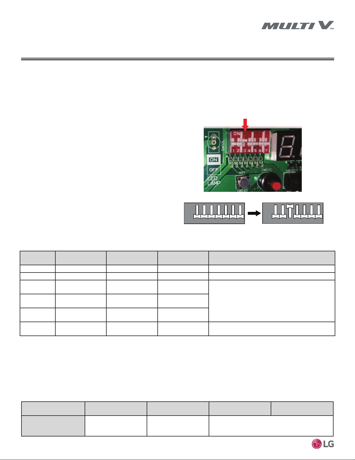
52
Multi V Ducted Indoor Units
Due to our policy of continuous product innovation, some specifications may change without notification.
©LG Electronics U.S.A., Inc., Englewood Cliffs, NJ. All rights reserved. “LG” is a registered trademark of LG Corp.
WIRING
DIP Switch Settings for Gen4 Equipment
Generation 4 Equipment
The latest versions of LG’s indoor units and outdoor (air/water source) units are designated Generation 4 (Gen 4). For Gen 4 units to operate
with Gen 4 features, the air conditioning system must meet the following requirements:
• All indoor units, heat recovery units, and air/water source units
must be Gen 4.
• All air/water source units must have Gen 4 software
installed.
• Air/water source units DIP switch 3 must be set to ON
(factory default setting is OFF).
• All controllers must support Gen 4 features.
Figure 41 shows the ODU DIP switch. Table 19 lists how combining
different components will affect system operation. Table 20 lists the
serial numbers of air and water source units that have Gen 4 soft-
ware. All air and water source units, indoor units, heat recovery units,
and controllers in a system must be Gen 4 compatible or the system
will not operate with Gen 4 features.
Air / Water
Source Units*
Indoor Unit(s)**
Heat Recovery
Unit(s)
Outdoor Unit DIP
Switch No. 3
Operation Status
Gen 4 Gen 4 ONLY Model 2A ONLY Must be ON System will operate WITH Gen. 4 features.
Gen 4 Gen 4 ONLY Model 2A ONLY OFF System will operate but WITHOUT Gen. 4 features.
Gen 4 Gen 4 ONLY
Any combination of
Models 1A, 2A
Must be OFF
(factory default)
Does NOT include Gen. 4 features. System will not
operate if DIP Switch No. 3 is ON, and an error code will
be generated.
Gen 4
Any combination of
Gen 2 and Gen 4
Model 2A ONLY
Must be OFF
(factory default)
Gen 4
Any combination of
Gen 2 and Gen 4
Any combination of
Models 1A, 2A
Must be OFF
(factory default)
Gen 2
Any combination of
Gen 2 and Gen 4
Any combination of
Models 0A****, 1A, 2A
N/A*** Does not include Gen. 4 features.
Figure 41: Location and Setting of ODU DIP Switch 3
1 2 76543
1 2 76543
ON
OFF
1 2 76543
1 2 76543
ON
OFF
ODU/WSU DIP Switch No. 3
Table 19: System Component Combinations and Operation Status
*Gen 4 Air/Water Source Units = Multi V IV or Multi V Water IV with Gen 4 software (see table below for Gen 4 serial numbers) or Multi V S.
Gen 2 Air/Water Source Units = Multi V II, Multi V III, Multi V IV without Gen. 4 software, Multi V Water II, Multi V Water IV without Gen. 4
software, Multi V Mini, Multi V Water Mini, or Multi V Space II.
**Gen 4 Indoor Units model numbers end in “4”; Gen 2 Indoor Units model numbers end in “2” or an “A”, including Hydro Kit.
***DIP Switch No. 3 on Gen 2 air/water source units is not related to Gen 4 features as it is with Gen 4 air/water source units.
****0A Model Heat Recovery units are not for use with Multi V IV, Multi V Water IV, or Multi V III heat recovery systems.
Air/Water Source Unit
Model Type
Multi V IV Air Source
Heat Pump
Multi V Air Source
Heat Recovery
Multi V IV Water Source
Heat Pump
Multi V IV Water Source
Heat Recovery
Serial Number of Air/Water
Source Units with
Gen 4 Software
502********* and Higher 503********* and Higher 504********* and Higher
Table 20: Serial Numbers of Air/Water Source Units with Gen 4 Software
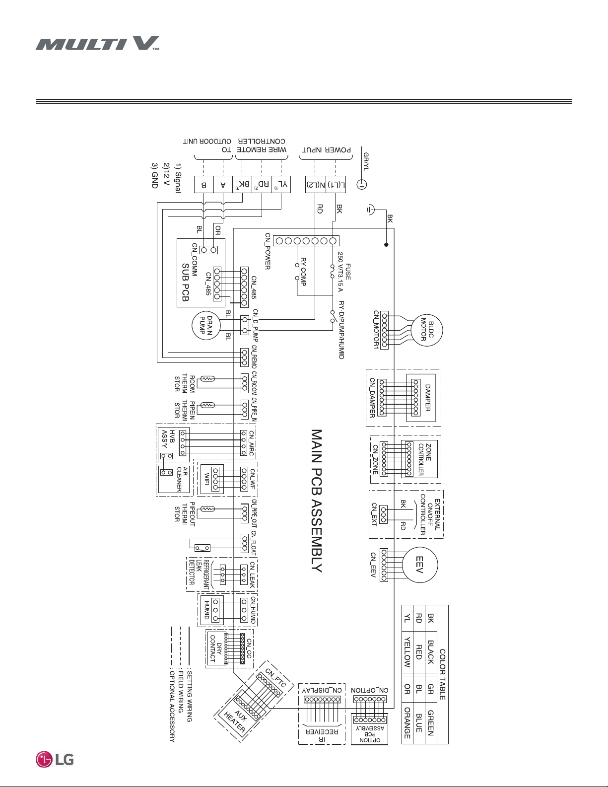
53
Installation Manual
Due to our policy of continuous product innovation, some specifications may change without notification.
©LG Electronics U.S.A., Inc., Englewood Cliffs, NJ. All rights reserved. “LG” is a registered trademark of LG Corp.
WIRING
High-Static Ducted BH Chassis
Figure 42: High-Static Ducted BH Chassis Wiring Diagram
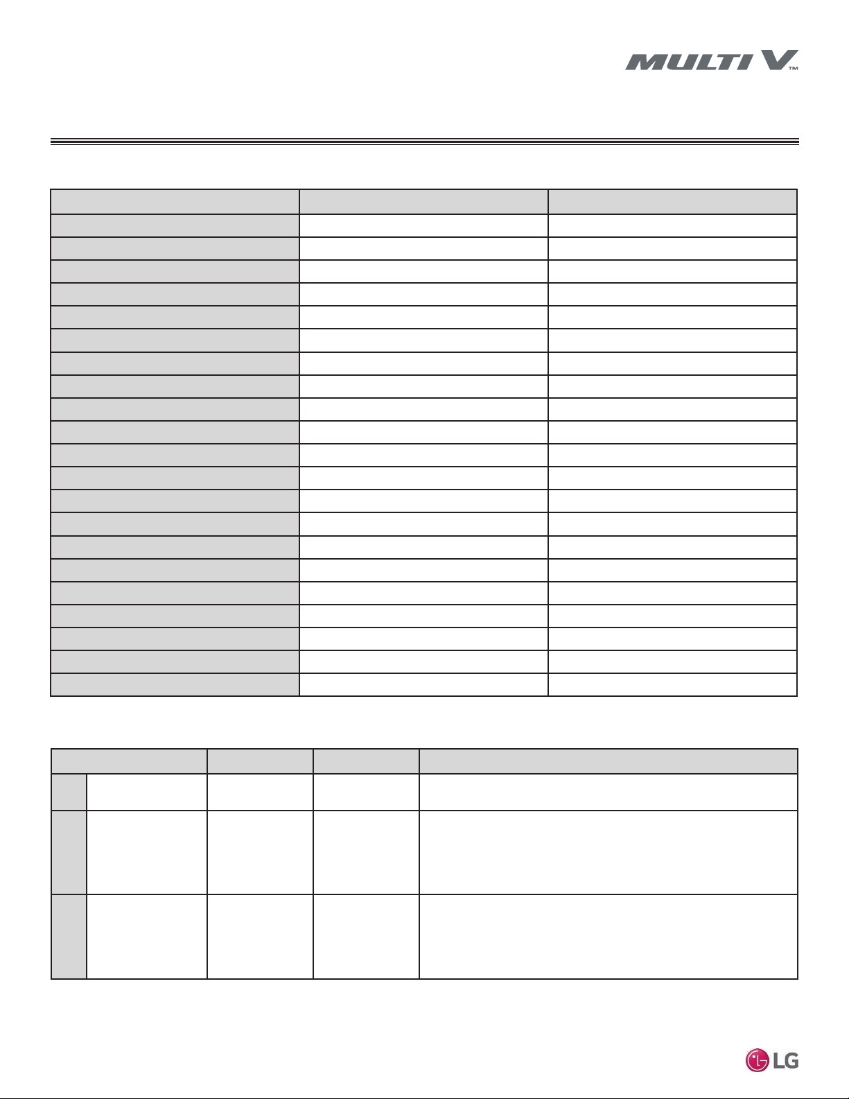
54
Multi V Ducted Indoor Units
Due to our policy of continuous product innovation, some specifications may change without notification.
©LG Electronics U.S.A., Inc., Englewood Cliffs, NJ. All rights reserved. “LG” is a registered trademark of LG Corp.
WIRING
High-Static Ducted BH Chassis
CONNECTOR PURPOSE FUNCTION
CN-POWER
AC Power supply AC Power line
CN-MOTOR1
Fan motor output Motor output of BLDC
CN-DAMPER
N / A N / A
CN-ZONE
Zone controller Zone controller connection
CN-EXT
External on / off controller External on / off Controller connection
CN-EEV
EEV Output EEV control output
CN-OPTION
Optional PCB EPROM Option PCB connection
CN-DISPLAY
Display Display of indoor status
CN-PTC
Auxiliary heater Connection for Auxiliary Heater
CN-CC
Dry contact Dry Contact connection
CN-HUMID
N / A N / A
CN-LEAK
Leak detector Leak detector connection
CN-FLOAT
Float switch input Float switch sensing
CN-PIPE/OUT
Discharge pipe sensor Pipe out thermistor
CN-WF
N / A N / A
CN-AIRC
N / A N / A
CN-PIPE/IN
Suction pipe sensor Pipe in thermistor
CN-ROOM
Room sensor Room air thermistor
CN-REMO
Wired remote controller Wired remote control connection
CN-D/PUMP
Drain pump output AC output for drain pump
CN-485
Communication Connection between indoor and outdoor units
*For Gen 4 Multi V ducted indoor units, DIP Switches 1, 2, 6 through 8 must be set to OFF. These DIP switches are used for
other models.
**To enable Generation 4 features, outdoor unit DIP Switch No. 3 must be set to ON. Please refer to the Multi V IV, Multi V Wa-
ter IV, Multi V S Engineering Manual for additional information.
DIP Switch Setting Off On Remarks
SW3
GROUP CONTROL Master Slave
Group control setting using 7-Day Programmable Controller; selects Master /
Slave on each indoor unit
SW4
DRY CONTACT
MODE
Variable Auto
Sets operation mode for optional Dry Contact accessory
1. Variable: Auto or Manual Mode can be set through 7-Day Programmable
Controller or Wireless Remote Controller (factory default setting is Auto if
there is no setting)
2. Auto: For Dry Contact, it is always Auto mode
SW5
CONTINUOUS FAN Off On
Selects continuous fan for ducted indoor units.
1. On: Indoor unit fan will always operate at a set fan speed, except when
the system is off, or the outdoor unit is in defrost mode (when the oudoor unit
is in defrost mode, the fan will operate at super low fan speed)
2. Off: Indoor unit fan speed can be changed by on / off
Table 21: High-Static Ducted BH Chassis Wiring Diagram
Table 22: BH Chassis DIP Switch Settings
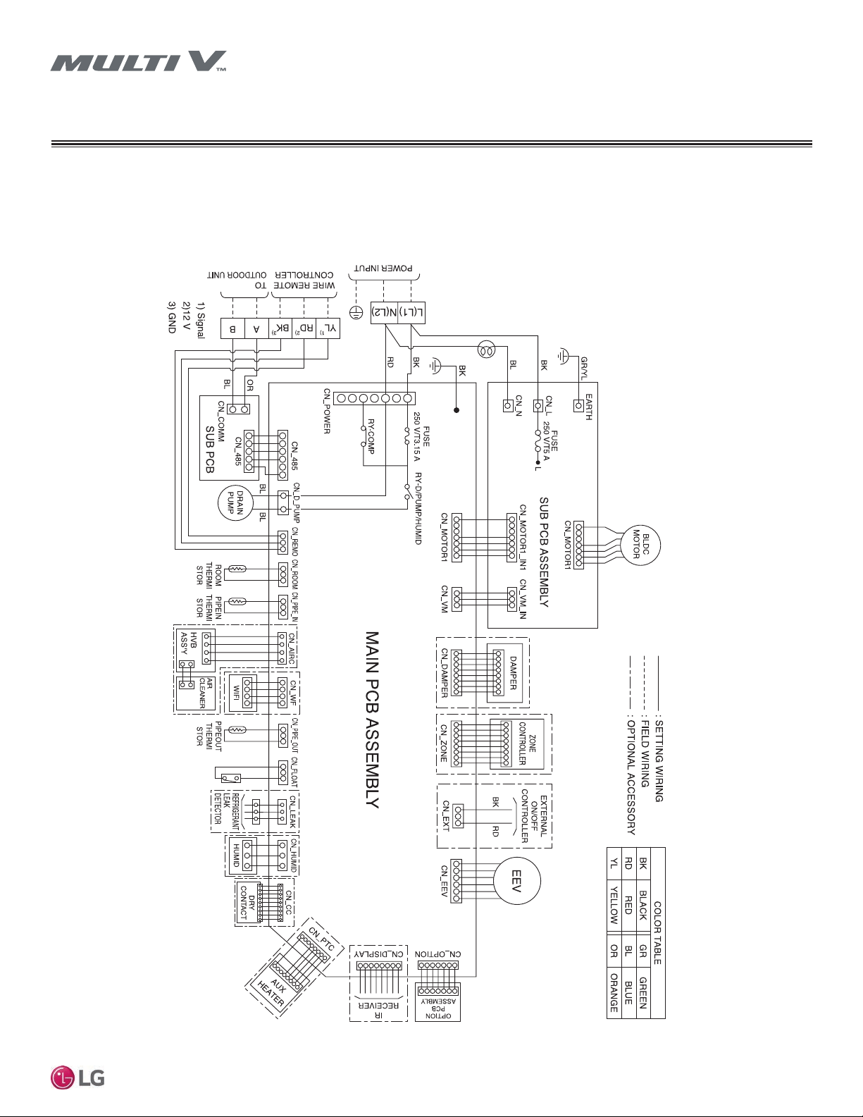
55
Installation Manual
Due to our policy of continuous product innovation, some specifications may change without notification.
©LG Electronics U.S.A., Inc., Englewood Cliffs, NJ. All rights reserved. “LG” is a registered trademark of LG Corp.
WIRING
High-Static Ducted BG Chassis
Figure 43: High-Static Ducted BG Chassis Wiring Diagram
Optional Connections
Figure 43 shows the control board for the BG chassis. Connect optional equipment to the control board as required for your system.
BG-MEZ61897818
56
Multi V Ducted Indoor Units
Due to our policy of continuous product innovation, some specifications may change without notification.
©LG Electronics U.S.A., Inc., Englewood Cliffs, NJ. All rights reserved. “LG” is a registered trademark of LG Corp.
CONNECTOR PURPOSE FUNCTION
CN-POWER
AC Power supply AC Power line
CN-MOTOR1
Fan motor output Motor output of BLDC
CN-VM
Sub PCB to Main PCB power supply Power supply connection
CN-DAMPER
N / A N / A
CN-ZONE
Zone controller Zone controller connection
CN-EXT
External on / off controller External on / off Controller connection
CN-EEV
EEV Output EEV control output
CN-OPTION
Optional PCB EPROM Option PCB connection
CN-DISPLAY
Display Display of indoor status
CN-PTC
Auxiliary heater Connection for Auxiliary Heater
CN-CC
Dry contact Dry Contact connection
CN-HUMID
N / A N / A
CN-LEAK
Leak detector Leak detector connection
CN-FLOAT
Float switch input Float switch sensing
CN-PIPE/OUT
Discharge pipe sensor Pipe out thermistor
CN-WF
N / A N / A
CN-AIRC
N / A N / A
CN-PIPE/IN
Suction pipe sensor Pipe in thermistor
CN-ROOM
Room sensor Room air thermistor
CN-REMO
Wired remote controller Wired remote control connection
CN-D/PUMP
Drain pump output AC output for drain pump
CN-485
Communication Connection between indoor and outdoor units
Table 23: High-Static Ducted BG Chassis Wiring Diagram
High-Static Ducted BG Chassis
WIRING
Table 24: BG Chassis DIP Switch Settings.
*For Gen 4 Multi V ducted indoor units, DIP Switches 1, 2, 6 through 8 must be set to OFF. These DIP switches are used for
other models.
**To enable Generation 4 features, outdoor unit DIP Switch No. 3 must be set to ON. Please refer to the Multi V IV, Multi V Wa-
ter IV, Multi V S Engineering Manual for additional information.
DIP Switch Setting Off On Remarks
SW3
GROUP CONTROL Master Slave
Group control setting using 7-Day Programmable Controller; selects Master /
Slave on each indoor unit
SW4
DRY CONTACT
MODE
Variable Auto
Sets operation mode for optional Dry Contact accessory
1. Variable: Auto or Manual Mode can be set through 7-Day Programmable
Controller or Wireless Remote Controller (factory default setting is Auto if
there is no setting)
2. Auto: For Dry Contact, it is always Auto mode
SW5
CONTINUOUS FAN Off On
Selects continuous fan for ducted indoor units.
1. On: Indoor unit fan will always operate at a set fan speed, except when
the system is off, or the outdoor unit is in defrost mode (when the oudoor unit
is in defrost mode, the fan will operate at super low fan speed)
2. Off: Indoor unit fan speed can be changed by on / off
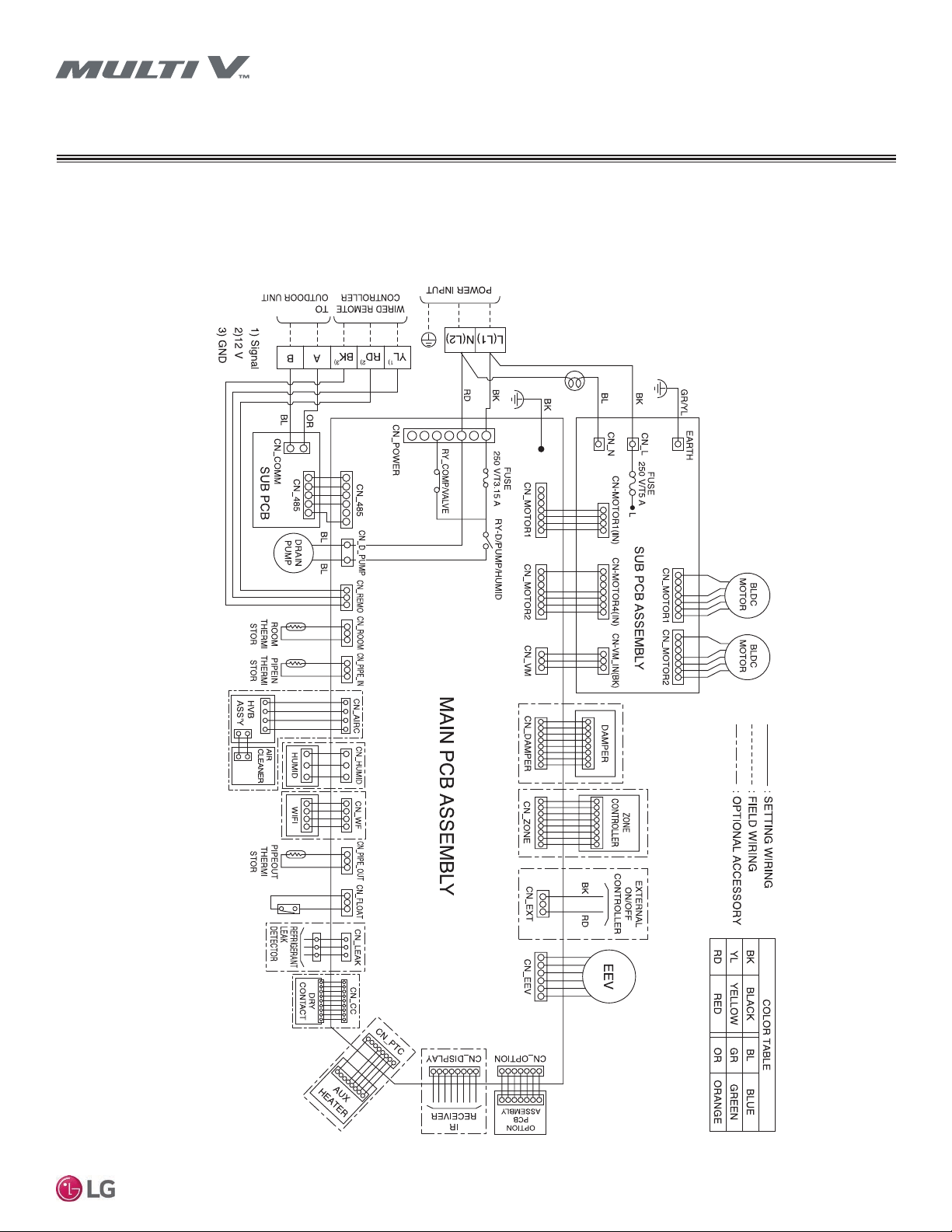
57
Installation Manual
Due to our policy of continuous product innovation, some specifications may change without notification.
©LG Electronics U.S.A., Inc., Englewood Cliffs, NJ. All rights reserved. “LG” is a registered trademark of LG Corp.
WIRING
High-Static Ducted BR Chassis
Figure 44: High-Static Ducted BR Chassis Wiring Diagram
Optional Connections
Figure 44 shows the control board for the BR chassis. Connect optional equipment to the control board as required for your system.
BR-MEZ66590610

58
Multi V Ducted Indoor Units
Due to our policy of continuous product innovation, some specifications may change without notification.
©LG Electronics U.S.A., Inc., Englewood Cliffs, NJ. All rights reserved. “LG” is a registered trademark of LG Corp.
WIRING
Table 25: High-Static Ducted BR Chassis Wiring Diagram
High-Static Ducted BR Chassis
CONNECTOR PURPOSE FUNCTION
CN-POWER
AC Power supply AC Power line
CN-MOTOR1
Fan motor output Motor output of BLDC
CN-MOTOR2
Fan motor output Motor output of BLDC
CN-VM
Sub PCB to Main PCB power supply Power supply connection
CN-DAMPER
N / A N / A
CN-ZONE
Zone controller Zone controller connection
CN-EXT
External on / off controller External on / off Controller connection
CN-EEV
EEV Output EEV control output
CN-OPTION
Optional PCB EPROM Option PCB connection
CN-DISPLAY
Display Display of indoor status
CN-PTC
Auxiliary heater Connection for Auxiliary Heater
CN-CC
Dry contact Dry Contact connection
CN-LEAK
Leak detector Leak detector connection
CN-FLOAT
Float switch input Float switch sensing
CN-PIPE/OUT
Discharge pipe sensor Pipe out thermistor
CN-WF
N / A N / A
CN-HUMID
N / A N / A
CN-AIRC
N / A N / A
CN-PIPE/IN
Suction pipe sensor Pipe in thermistor
CN-ROOM
Room sensor Room air thermistor
CN-REMO
Wired remote controller Wired remote control connection
CN-D/PUMP
Drain pump output AC output for drain pump
CN-485
Communication Connection between indoor and outdoor units
Table 26: BR Chassis DIP Switch Settings.
*For Gen 4 Multi V ducted indoor units, DIP Switches 1, 2, 6 through 8 must be set to OFF. These DIP switches are used for
other models.
**To enable Generation 4 features, outdoor unit DIP Switch No. 3 must be set to ON. Please refer to the Multi V IV, Multi V Wa-
ter IV, Multi V S Engineering Manual for additional information.
DIP Switch Setting Off On Remarks
SW3
GROUP CONTROL Master Slave
Group control setting using 7-Day Programmable Controller; selects Master /
Slave on each indoor unit
SW4
DRY CONTACT
MODE
Variable Auto
Sets operation mode for optional Dry Contact accessory
1. Variable: Auto or Manual Mode can be set through 7-Day Programmable
Controller or Wireless Remote Controller (factory default setting is Auto if
there is no setting)
2. Auto: For Dry Contact, it is always Auto mode
SW5
CONTINUOUS FAN Off On
Selects continuous fan for ducted indoor units.
1. On: Indoor unit fan will always operate at a set fan speed, except when
the system is off, or the outdoor unit is in defrost mode (when the oudoor unit
is in defrost mode, the fan will operate at super low fan speed)
2. Off: Indoor unit fan speed can be changed by on / off
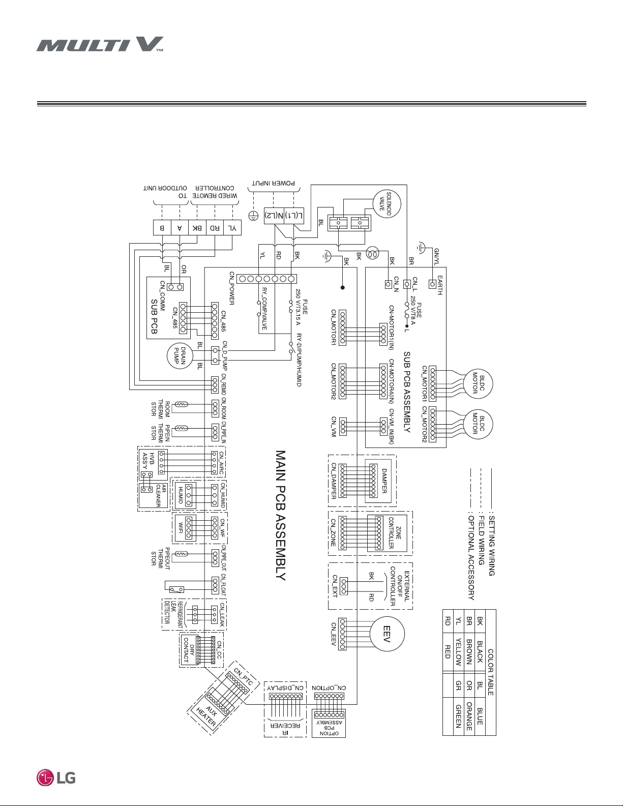
59
Installation Manual
Due to our policy of continuous product innovation, some specifications may change without notification.
©LG Electronics U.S.A., Inc., Englewood Cliffs, NJ. All rights reserved. “LG” is a registered trademark of LG Corp.
WIRING
High-Static Ducted B8 Chassis
Figure 45: High-Static Ducted B8 Chassis Wiring Diagram
Optional Connections
Figure 45 shows the control board for the B8 chassis. Connect optional equipment to the control board as required for your system.
B8-MEZ66590612

60
Multi V Ducted Indoor Units
Due to our policy of continuous product innovation, some specifications may change without notification.
©LG Electronics U.S.A., Inc., Englewood Cliffs, NJ. All rights reserved. “LG” is a registered trademark of LG Corp.
WIRING
Table 27: High-Static Ducted B8 Chassis Wiring Diagram
High-Static Ducted B8 Chassis
CONNECTOR PURPOSE FUNCTION
CN-POWER
AC Power supply AC Power line
CN-MOTOR1
Fan motor output Motor output of BLDC
CN-MOTOR2
Fan motor output Motor output of BLDC
CN-VM
Sub PCB to Main PCB power supply Power supply connection
CN-DAMPER
N / A N / A
CN-ZONE
Zone controller Zone controller connection
CN-EXT
External on / off controller External on / off Controller connection
CN-EEV
EEV Output EEV control output
CN-OPTION
Optional PCB EPROM Option PCB connection
CN-DISPLAY
Display Display of indoor status
CN-PTC
Auxiliary heater Connection for Auxiliary Heater
CN-CC
Dry contact Dry Contact connection
CN-LEAK
Leak detector Leak detector connection
CN-FLOAT
Float switch input Float switch sensing
CN-PIPE/OUT
Discharge pipe sensor Pipe out thermistor
CN-WF
N / A N / A
CN-HUMID
N / A N / A
CN-AIRC
N / A N / A
CN-PIPE/IN
Suction pipe sensor Pipe in thermistor
CN-ROOM
Room sensor Room air thermistor
CN-REMO
Wired remote controller Wired remote control connection
CN-D/PUMP
Drain pump output AC output for drain pump
CN-485
Communication Connection between indoor and outdoor units
Table 28: B8 Unit DIP Switch Settings.
*For Gen 4 Multi V ducted indoor units, DIP Switches 1, 2, 6 through 8 must be set to OFF. These DIP switches are used for
other models.
**To enable Generation 4 features, outdoor unit DIP Switch No. 3 must be set to ON. Please refer to the Multi V IV, Multi V Wa-
ter IV, Multi V S Engineering Manual for additional information.
DIP Switch Setting Off On Remarks
SW3
GROUP CONTROL Master Slave
Group control setting using 7-Day Programmable Controller; selects Master /
Slave on each indoor unit
SW4
DRY CONTACT
MODE
Variable Auto
Sets operation mode for optional Dry Contact accessory
1. Variable: Auto or Manual Mode can be set through 7-Day Programmable
Controller or Wireless Remote Controller (factory default setting is Auto if
there is no setting)
2. Auto: For Dry Contact, it is always Auto mode
SW5
CONTINUOUS FAN Off On
Selects continuous fan for ducted indoor units.
1. On: Indoor unit fan will always operate at a set fan speed, except when
the system is off, or the outdoor unit is in defrost mode (when the oudoor unit
is in defrost mode, the fan will operate at super low fan speed)
2. Off: Indoor unit fan speed can be changed by on / off
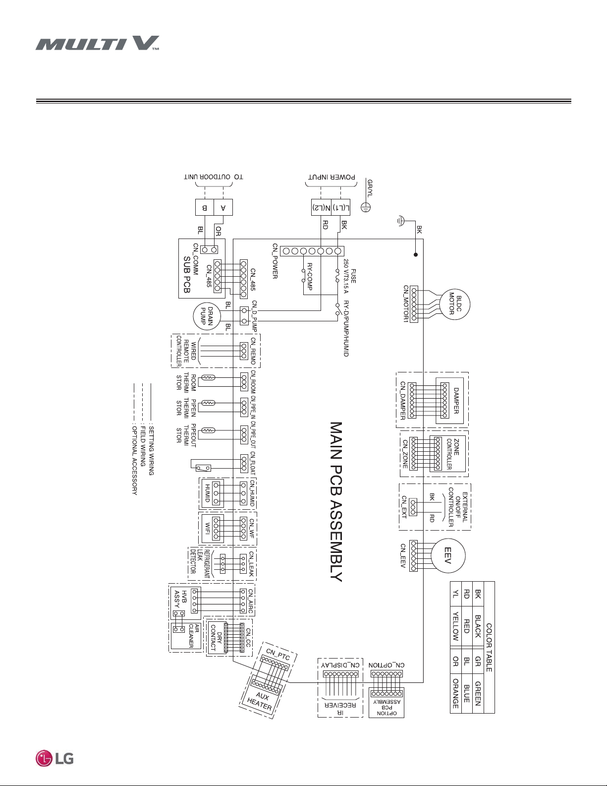
61
Installation Manual
Due to our policy of continuous product innovation, some specifications may change without notification.
©LG Electronics U.S.A., Inc., Englewood Cliffs, NJ. All rights reserved. “LG” is a registered trademark of LG Corp.
WIRING
Low-Static Ducted L1 Chassis
Figure 46: Low-Static Ducted L1 Chassis Wiring Diagram
Optional Connections
Figure 46 shows the control board for the L1 chassis. Connect optional equipment to the control board as required for your system.
L1-MEZ66590602

62
Multi V Ducted Indoor Units
Due to our policy of continuous product innovation, some specifications may change without notification.
©LG Electronics U.S.A., Inc., Englewood Cliffs, NJ. All rights reserved. “LG” is a registered trademark of LG Corp.
WIRING
Table 29: Low-Static Ducted L1 Chassis Wiring Diagram
Low-Static Ducted L1 Chassis
CONNECTOR PURPOSE FUNCTION
CN-POWER
AC Power supply AC Power line
CN-MOTOR1
Fan motor output Motor output of BLDC
CN-DAMPER
N / A N / A
CN-ZONE
Zone controller Zone controller connection
CN-EXT
External on / off controller External on / off Controller connection
CN-EEV
EEV Output EEV control output
CN-OPTION
Optional PCB EPROM Option PCB connection
CN-DISPLAY
Display Display of indoor status
CN-PTC
Auxiliary heater Connection for Auxiliary Heater
CN-CC
Dry contact Dry Contact connection
CN-AIRC
N / A N / A
CN-LEAK
Leak detector Leak detector connection
CN-WF
N / A N / A
CN-HUMID
N / A N / A
CN-FLOAT
Float switch input Float switch sensing
CN-PIPE/OUT
Discharge pipe sensor Pipe out thermistor
CN-PIPE/IN
Suction pipe sensor Pipe in thermistor
CN-ROOM
Room sensor Room air thermistor
CN-REMO
Wired remote controller Wired remote control connection
CN-D/PUMP
Drain pump output AC output for drain pump
CN-485
Communication Connection between indoor and outdoor units
Table 30: L1 Unit DIP Switch Settings.
*For Gen 4 Multi V ducted indoor units, DIP switches 1, 2, 6 through 8 must be set to OFF. These DIP switches are used for
other models.
**To enable Generation 4 features, outdoor unit DIP Switch No. 3 must be set to ON. Please refer to the Multi V IV, Multi V Wa-
ter IV, Multi V S Engineering Manual for additional information.
DIP Switch Setting Off On Remarks
SW3
GROUP CONTROL Master Slave
Group control setting using 7-Day Programmable Controller; selects Master /
Slave on each indoor unit
SW4
DRY CONTACT
MODE
Variable Auto
Sets operation mode for optional Dry Contact accessory
1. Variable: Auto or Manual Mode can be set through 7-Day Programmable
Controller or Wireless Remote Controller (factory default setting is Auto if
there is no setting)
2. Auto: For Dry Contact, it is always Auto mode
SW5
CONTINUOUS FAN Off On
Selects continuous fan for ducted indoor units.
1. On: Indoor unit fan will always operate at a set fan speed, except when
the system is off, or the outdoor unit is in defrost mode (when the oudoor unit
is in defrost mode, the fan will operate at super low fan speed)
2. Off: Indoor unit fan speed can be changed by on / off
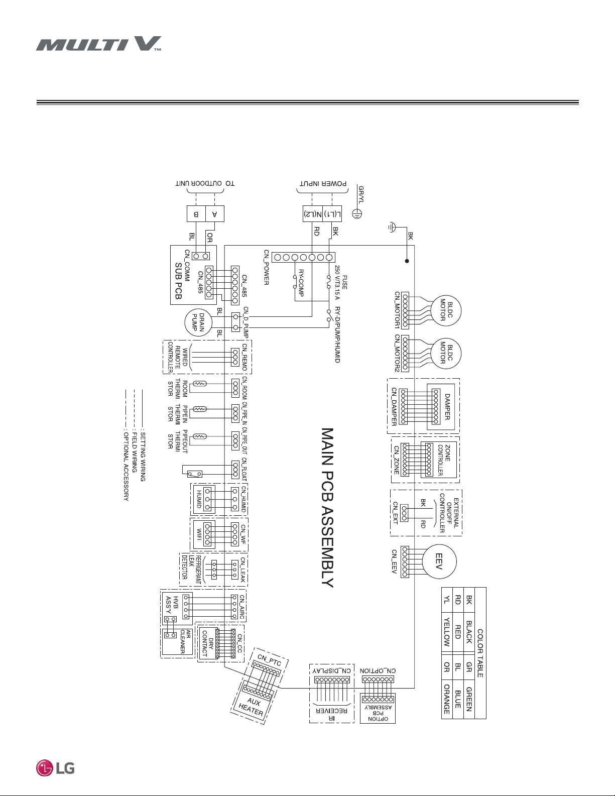
63
Installation Manual
Due to our policy of continuous product innovation, some specifications may change without notification.
©LG Electronics U.S.A., Inc., Englewood Cliffs, NJ. All rights reserved. “LG” is a registered trademark of LG Corp.
WIRING
Low-Static Ducted L2/L3 Chassis
Figure 47: Low-Static Ducted L2/L3 Chassis Wiring Diagram
Optional Connections
Figure 47 shows the control board for the L2/L3 chassis. Connect optional equipment to the control board as required for your system.
L2L3-MEZ66590604

64
Multi V Ducted Indoor Units
Due to our policy of continuous product innovation, some specifications may change without notification.
©LG Electronics U.S.A., Inc., Englewood Cliffs, NJ. All rights reserved. “LG” is a registered trademark of LG Corp.
WIRING
Table 31: Low-Static Ducted L2/L3 Chassis Wiring Diagram
Low-Static Ducted L2/L3 Chassis
CONNECTOR PURPOSE FUNCTION
CN-POWER
AC Power supply AC Power line
CN-MOTOR1
Fan motor output Motor output of BLDC
CN-MOTOR2
Fan motor output Motor output of BLDC
CN-DAMPER
N / A N / A
CN-ZONE
Zone controller Zone controller connection
CN-EXT
External on / off controller External on / off Controller connection
CN-EEV
EEV Output EEV control output
CN-OPTION
Optional PCB EPROM Option PCB connection
CN-DISPLAY
Display Display of indoor status
CN-PTC
Auxiliary heater Connection for Auxiliary Heater
CN-CC
Dry contact Dry Contact connection
CN-AIRC
N / A N / A
CN-LEAK
Leak detector Leak detector connection
CN-WF
N / A N / A
CN-HUMID
N / A N / A
CN-FLOAT
Float switch input Float switch sensing
CN-PIPE/OUT
Discharge pipe sensor Pipe out thermistor
CN-PIPE/IN
Suction pipe sensor Pipe in thermistor
CN-ROOM
Room sensor Room air thermistor
CN-REMO
Wired remote controller Wired remote control connection
CN-D/PUMP
Drain pump output AC output for drain pump
CN-485
Communication Connection between indoor and outdoor units
Table 32: L2, L3 Unit DIP Switch Settings.
*For Gen 4 Multi V ducted indoor units, DIP switches 1, 2, 6 through 8 must be set to OFF. These DIP switches are used for
other models.
**To enable Generation 4 features, outdoor unit DIP Switch No. 3 must be set to ON. Please refer to the Multi V IV, Multi V Wa-
ter IV, Multi V S Engineering Manual for additional information.
DIP Switch Setting Off On Remarks
SW3
GROUP CONTROL Master Slave
Group control setting using 7-Day Programmable Controller; selects Master /
Slave on each indoor unit
SW4
DRY CONTACT
MODE
Variable Auto
Sets operation mode for optional Dry Contact accessory
1. Variable: Auto or Manual Mode can be set through 7-Day Programmable
Controller or Wireless Remote Controller (factory default setting is Auto if
there is no setting)
2. Auto: For Dry Contact, it is always Auto mode
SW5
CONTINUOUS FAN Off On
Selects continuous fan for ducted indoor units.
1. On: Indoor unit fan will always operate at a set fan speed, except when
the system is off, or the outdoor unit is in defrost mode (when the oudoor unit
is in defrost mode, the fan will operate at super low fan speed)
2. Off: Indoor unit fan speed can be changed by on / off
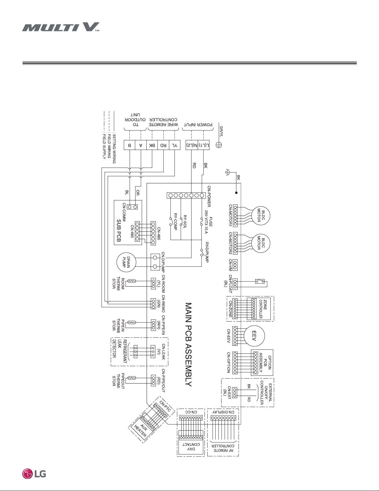
65
Installation Manual
Due to our policy of continuous product innovation, some specifications may change without notification.
©LG Electronics U.S.A., Inc., Englewood Cliffs, NJ. All rights reserved. “LG” is a registered trademark of LG Corp.
WIRING
Low-Static Built-In B3/B4 Chassis
Figure 48: Low-Static Built-In B3/B4 Chassis Wiring Diagram
Optional Connections
Figure 48 shows the control board for the L1 chassis. Connect optional equipment to the control board as required for your system.
B3B4-MEZ51186311
66
Multi V Ducted Indoor Units
Due to our policy of continuous product innovation, some specifications may change without notification.
©LG Electronics U.S.A., Inc., Englewood Cliffs, NJ. All rights reserved. “LG” is a registered trademark of LG Corp.
WIRING
Table 33: Low-Static Built-In B3/B4 Chassis Wiring Diagram
Low-Static Built-In B3/B4 Chassis
CONNECTOR PURPOSE FUNCTION
CN-POWER
AC Power supply AC Power line
CN-MOTOR1
Fan motor output Motor output of BLDC
CN-MOTOR2
Fan motor output Motor output of BLDC
CN-VM
Sub PC power supply Power supply connection
CN-FLOAT
Float switch input Float switch sensing
CN-ZONE
Zone controller Zone controller connection
CN-EEV
EEV Output EEV control output
CN-OPTION
Optional PCB EPROM Option PCB connection
CN-EXT
External ON / OFF controller External ON / OFF controller connection
CN-DISPLAY
Display Display of indoor status
CN-CC
Dry contact Dry Contact connection
CN-PTC
Auxiliary heater Connection for Auxiliary Heater
CN-PIPE/OUT
Discharge pipe sensor Pipe out thermistor
CN-LEAK
Refrigerant leak detector Refrigerant leak detector connection
CN-PIPE/IN
Suction pipe sensor Pipe in thermistor
CN-REMO
Wired remote controller Wired remote control connection
CN-ROOM
Room sensor Room air thermistor
CN-D/PUMP
Drain pump output AC output for drain pump
CN-485
Communication Connection between indoor and outdoor units
Table 34: B3, B4 Unit DIP Switch Settings.
*For Gen 4 Multi V ducted indoor units, DIP switches 1, 2, 6 through 8 must be set to OFF. These DIP switches are used for
other models.
**To enable Generation 4 features, outdoor unit DIP Switch No. 3 must be set to ON. Please refer to the Multi V IV, Multi V Wa-
ter IV, Multi V S Engineering Manual for additional information.
DIP Switch Setting Off On Remarks
SW3
GROUP CONTROL Master Slave
Group control setting using 7-Day Programmable Controller; selects Master /
Slave on each indoor unit
SW4
DRY CONTACT
MODE
Variable Auto
Sets operation mode for optional Dry Contact accessory
1. Variable: Auto or Manual Mode can be set through 7-Day Programmable
Controller or Wireless Remote Controller (factory default setting is Auto if
there is no setting)
2. Auto: For Dry Contact, it is always Auto mode
SW5
CONTINUOUS FAN Off On
Selects continuous fan for ducted indoor units.
1. On: Indoor unit fan will always operate at a set fan speed, except when
the system is off, or the outdoor unit is in defrost mode (when the oudoor unit
is in defrost mode, the fan will operate at super low fan speed)
2. Off: Indoor unit fan speed can be changed by on / off
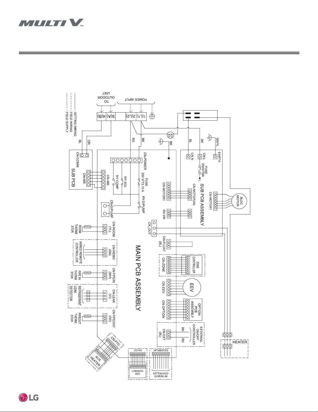
67
Installation Manual
Due to our policy of continuous product innovation, some specifications may change without notification.
©LG Electronics U.S.A., Inc., Englewood Cliffs, NJ. All rights reserved. “LG” is a registered trademark of LG Corp.
WIRING
Vertical Air Handler NJ Chassis
Figure 49: Vertical Air Handler NJ Chassis Wiring Diagram
Optional Connections
Figure 49 shows the control board for the NJ chassis. Connect optional equipment to the control board as required for your system.
NJ-MEZ62689314

68
Multi V Ducted Indoor Units
Due to our policy of continuous product innovation, some specifications may change without notification.
©LG Electronics U.S.A., Inc., Englewood Cliffs, NJ. All rights reserved. “LG” is a registered trademark of LG Corp.
WIRING
Vertical Air Handler NJ Chassis
Table 35: NJ Frame Wiring Diagram Legend.
Table 36: NJ Frame DIP Switch Settings.
Terminal Purpose Function
CN-POWER AC Power supply AC Power line
CN-MOTOR1 Fan motor output Motor output of BLDC
RV-VM Sub PC power supply Power supply connection
CN_OUT Heater Connection for heater
CN-FLOAT Float switch input Float switch sensing
CN-ZONE Zone controller Zone controller connection
CN-EEV EEV Output EEV control output
CN-OPTION Optional PCB EPROM Option PCB connection
CN-EXT
External ON / OFF controller External ON / OFF controller connection
CN-DISPLAY Display Display of indoor status
CN-CC Dry contact Dry Contact connection
CN-PTC
Auxiliary heater Auxiliary heater connection
CN-PIPE/OUT (RD) Discharge pipe sensor Pipe out thermistor
CN-LEAK (VI) Refrigerant leak detector Refrigerant leak detector connection
CN-PIPE/IN (WH) Suction pipe sensor Pipe in thermistor
CN-REMO (GN) Wired remote controller Wired remote control connection
CN-ROOM (YL) Room sensor Room air thermistor
CN-D/PUMP Drain pump output AC output for drain pump
CN-485 Communication Connection between indoor and outdoor units
*For Gen 4 Multi V vertical air handler indoor units, DIP switches 1, 2, 7 and 8 must be set to OFF. These DIP switches are
used for other models.
**To enable Generation 4 features, outdoor unit DIP Switch No. 3 must be set to ON. Please refer to the Multi V IV, Multi V Wa-
ter IV, Multi V S Engineering Manual for additional information.
DIP Switch Setting Off On Remarks
SW3
GROUP CONTROL Master Slave
Group control setting using 7-Day Programmable Controller; selects Master /
Slave on each indoor unit
SW4
DRY CONTACT
MODE
Variable Auto
Sets operation mode for optional Dry Contact accessory
1. Variable: Auto or Manual Mode can be set through 7-Day Programmable
Controller or Wireless Remote Controller (factory default setting is Auto if
there is no setting)
2. Auto: For Dry Contact, it is always Auto mode
SW5
CONTINUOUS FAN Off On
Selects continuous fan for ducted indoor units.
1. On: Indoor unit fan will always operate at a set fan speed, except when
the system is off, or the outdoor unit is in defrost mode (when the oudoor unit
is in defrost mode, the fan will operate at super low fan speed)
2. Off: Indoor unit fan speed can be changed by on / off
SW6
HEATER INTERLOCK Off On
Selects heater interlock function for vertical air handler units
1. On: Automatic (heater will automatically operate during heating mode)
2. Off: Manual (heater needs to be manually turned on during heating mode)
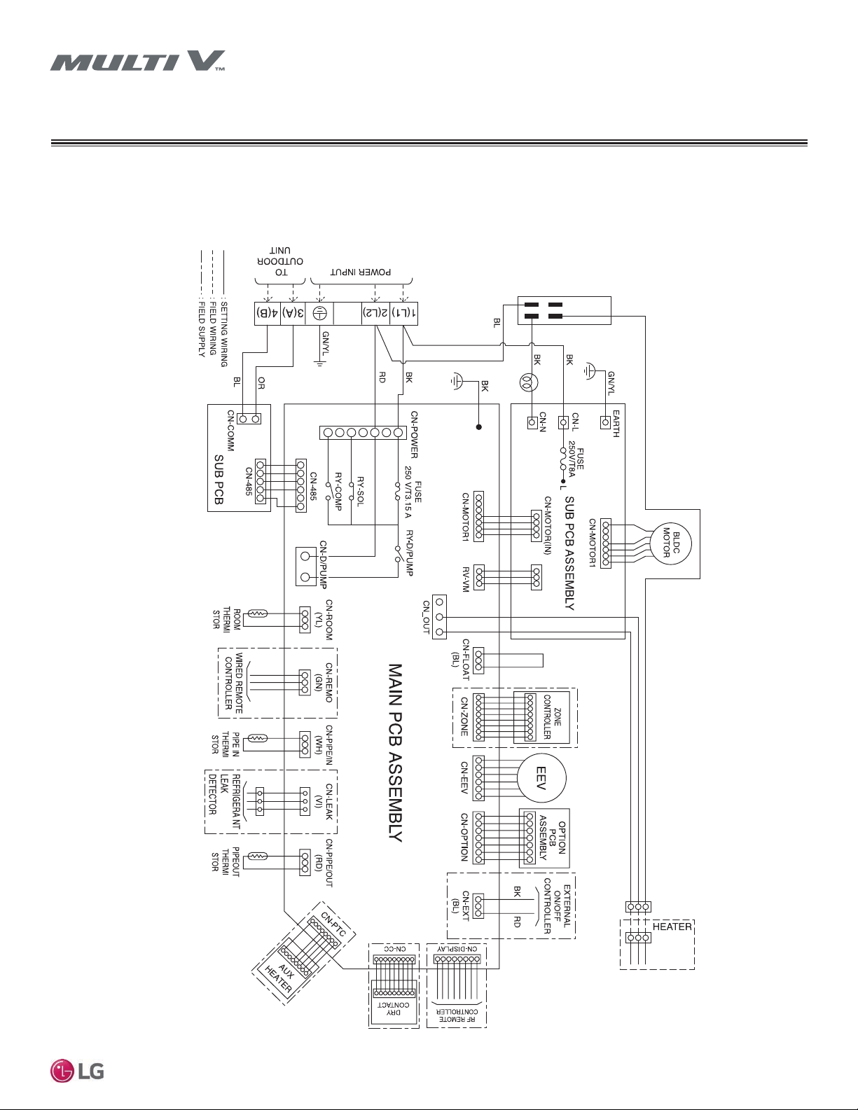
69
Installation Manual
Due to our policy of continuous product innovation, some specifications may change without notification.
©LG Electronics U.S.A., Inc., Englewood Cliffs, NJ. All rights reserved. “LG” is a registered trademark of LG Corp.
WIRING
Vertical Air Handler NK Chassis
Figure 50: Vertical Air Handler NK Chassis Wiring Diagram
Optional Connections
Figure 49 shows the control board for the NK chassis. Connect optional equipment to the control board as required for your system.
NK-MEZ62689315
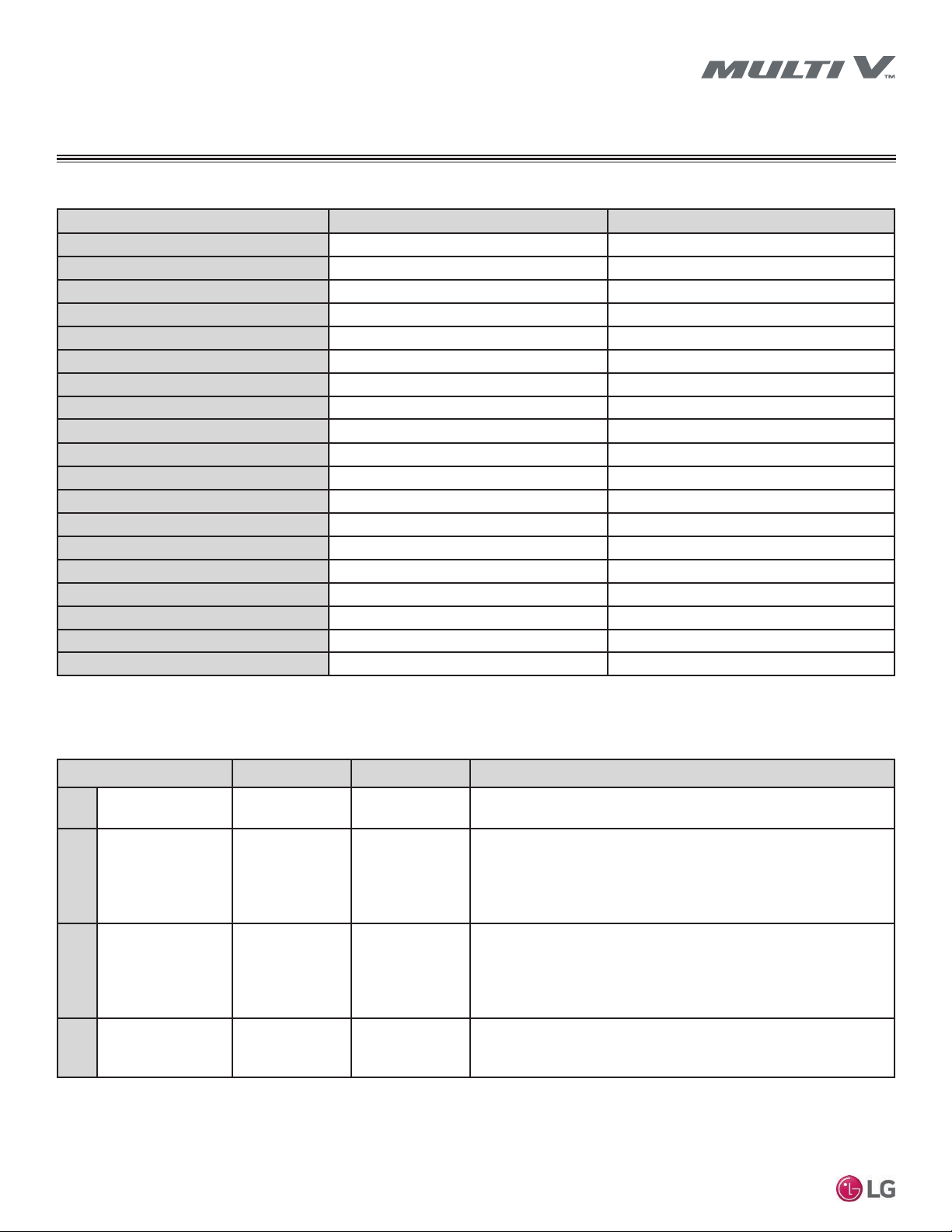
70
Multi V Ducted Indoor Units
Due to our policy of continuous product innovation, some specifications may change without notification.
©LG Electronics U.S.A., Inc., Englewood Cliffs, NJ. All rights reserved. “LG” is a registered trademark of LG Corp.
WIRING
Vertical Air Handler NK Chassis
Table 37: NK Frame Wiring Diagram Legend.
Table 38: NK Frame DIP Switch Settings.
Terminal Purpose Function
CN-POWER AC Power supply AC Power line
CN-MOTOR1 Fan motor output Motor output of BLDC
RV-VM Sub PC power supply Power supply connection
CN_OUT Heater Connection for heater
CN-FLOAT Float switch input Float switch sensing
CN-ZONE Zone controller Zone controller connection
CN-EEV EEV Output EEV control output
CN-OPTION Optional PCB EPROM Option PCB connection
CN-EXT
External ON / OFF controller External ON / OFF controller connection
CN-DISPLAY Display Display of indoor status
CN-CC Dry contact Dry Contact connection
CN-PTC
Auxiliary heater Auxiliary heater connection
CN-PIPE/OUT (RD) Discharge pipe sensor Pipe out thermistor
CN-LEAK (VI) Refrigerant leak detector Refrigerant leak detector connection
CN-PIPE/IN (WH) Suction pipe sensor Pipe in thermistor
CN-REMO (GN) Wired remote controller Wired remote control connection
CN-ROOM (YL) Room sensor Room air thermistor
CN-D/PUMP Drain pump output AC output for drain pump
CN-485 Communication Connection between indoor and outdoor units
*For Gen 4 Multi V vertical air handler indoor units, DIP switches 1, 2, 7 and 8 must be set to OFF. These DIP switches are
used for other models.
**To enable Generation 4 features, outdoor unit DIP Switch No. 3 must be set to ON. Please refer to the Multi V IV, Multi V Wa-
ter IV, Multi V S Engineering Manual for additional information.
DIP Switch Setting Off On Remarks
SW3
GROUP CONTROL Master Slave
Group control setting using 7-Day Programmable Controller; selects Master /
Slave on each indoor unit
SW4
DRY CONTACT
MODE
Variable Auto
Sets operation mode for optional Dry Contact accessory
1. Variable: Auto or Manual Mode can be set through 7-Day Programmable
Controller or Wireless Remote Controller (factory default setting is Auto if
there is no setting)
2. Auto: For Dry Contact, it is always Auto mode
SW5
CONTINUOUS FAN Off On
Selects continuous fan for ducted indoor units.
1. On: Indoor unit fan will always operate at a set fan speed, except when
the system is off, or the outdoor unit is in defrost mode (when the oudoor unit
is in defrost mode, the fan will operate at super low fan speed)
2. Off: Indoor unit fan speed can be changed by on / off
SW6
HEATER INTERLOCK Off On
Selects heater interlock function for vertical air handler units
1. On: Automatic (heater will automatically operate during heating mode)
2. Off: Manual (heater needs to be manually turned on during heating mode)
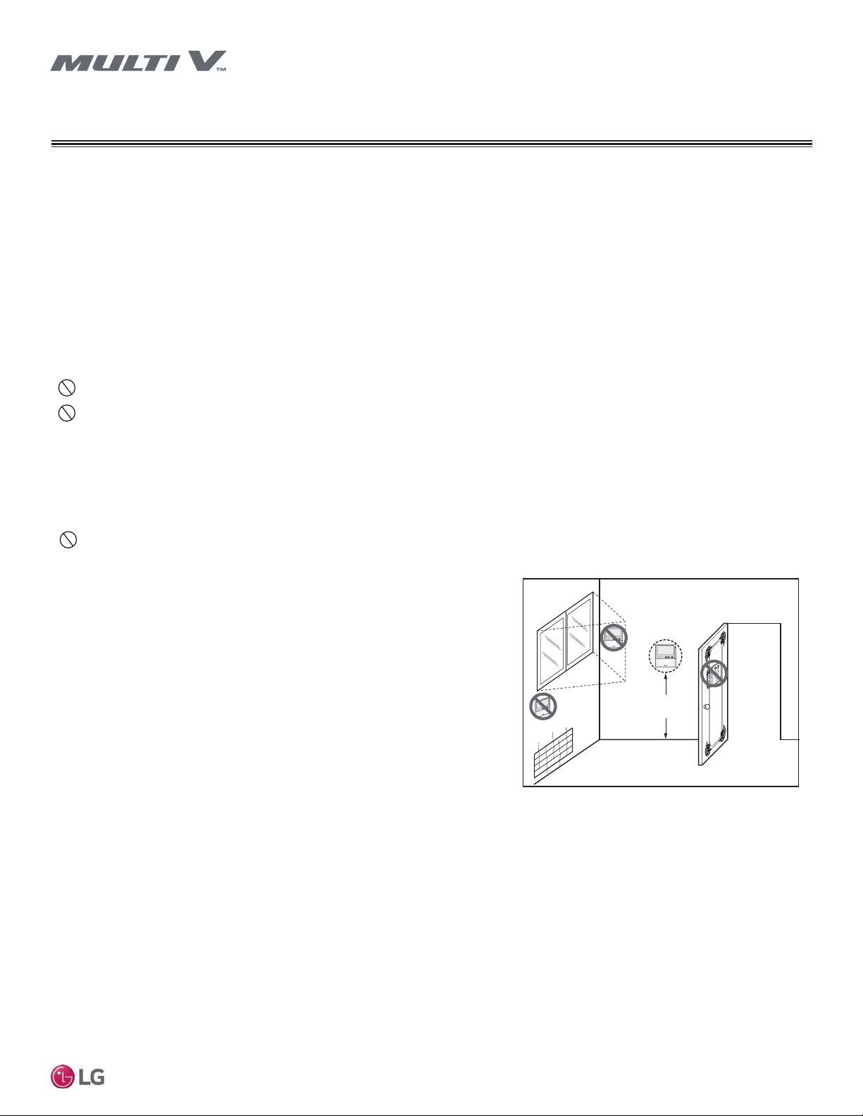
71
Installation Manual
Due to our policy of continuous product innovation, some specifications may change without notification.
©LG Electronics U.S.A., Inc., Englewood Cliffs, NJ. All rights reserved. “LG” is a registered trademark of LG Corp.
Wall-Mounted Sensor Installation
Proper indoor unit operation depends on the location of the room sensor. A good location will protect the zone controller from direct sunlight
and external local sources of water vapor, and heated or cooled air. If no mounting height was specified by the building designer, place the
handy box approximately fifty-five (55) inches above the finished floor.
• It may be necessary to use a handy box that is sized in metric units, depending on the controller model. Check with your LG representative
to verify which size of handy box is needed for the zone controller in question.
• Use only LG-supplied communications cable. Using eld-supplied cable may result in communications problems between the zone control-
ler and the indoor unit.
• Maintain the minimum distance required between the communications cable and power wiring. The minimum required space between
the two is dependent on the voltage of the power wiring. Refer to the appropriate Multi V Outdoor Unit Engineering Manual for minimum
distance specications.
Do not route power wiring and communications cables in the same conduit.
Do not cut the quick-connect plugs off or adjust the length of the cable. Keep the communications cable away from high voltage wires
and electromagnetic field (EMF) producing equipment.
WIRING
Wall-Mounted Controller Installation
Since the room temperature sensor is inside the remote controller, the remote controller should be installed in a place away from direct sun-
light, high humidity and direct supply of hot or cold air to maintain proper space temperature. Install the remote controller about 5 ft above
the floor in an area with good air circulation and an average temperature.
Do not install the remote controller where it can be affected by the following:
• Drafts or dead spots behind doors and in corners
• Hot or cold air from ducts
• Radiant heat from sun or appliances
• Concealed pipes and chimneys
• Uncontrolled areas such as an outside wall behind the remote controller
This remote controller is equipped with a seven segment LED display. For proper
display of the remote controller LEDs, the remote controller should be installed prop-
erly as shown below. The standard height is 4 - 5 ft from floor level.
1. Pull communications cable between the zone controller handy box (if used) and
the indoor unit. The wall-mounted zone controller comes with a thirty (33) foot
length of cable.
2. Store a minimal amount of cable in the handy box. Any additional cable should be
coiled and stored near the indoor unit control panel.
3. If additional cable length is needed, order a thirty-three (33) foot LG Wired Re-
mote Group Control Extension cable (Model No. PZCWRC1).
4. If the cable between the zone controller and the indoor unit is too long, do not cut the cable and shorten. Coil any spare communications
cable, tie-wrap it, and leave it next to the indoor unit location.
5ft
no
no
no
yes
Remote Controller
TEMP
Remote Controller
TEMP
Remote Controller
TEMP
Figure 51: Wired Remote Controller Installation
Optional Wall-Mounted Sensor and Controller
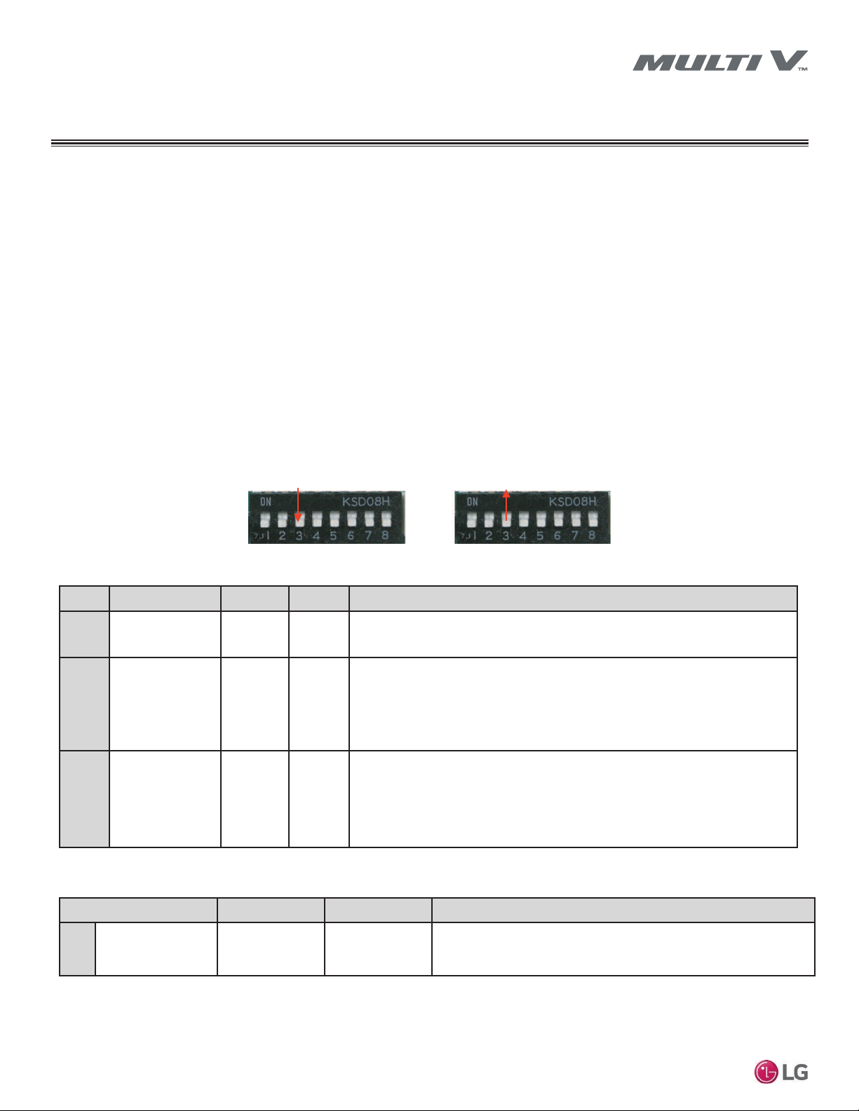
72
Multi V Ducted Indoor Units
Due to our policy of continuous product innovation, some specifications may change without notification.
©LG Electronics U.S.A., Inc., Englewood Cliffs, NJ. All rights reserved. “LG” is a registered trademark of LG Corp.
CONTROLS SETUP
To Select MASTER:
No. 3: Off
To Select SLAVE:
No. 3: On
Figure 52: Ducted IDU Master/Slave DIP Switch Settings
Controlling the Indoor Unit
The method and configuration of controlling the indoor unit will vary according to your system’s requirements.
• It is possible to control up to 16 indoor units with one wired remote controller.
• Set only one indoor unit in a group to master; set the others to slave.
• This indoor unit can be connected in a control group with any other types of LG indoor units.
• It is possible to use a wireless remote controller at the same time as the wall controller.
• It is possible to connect a dry contact and central controller at the same time (to a master indoor unit only).
• A central controller can control all indoor units in a group by controlling the master unit of the group.
• Slave indoor units can not be individually controlled by the central controller.
DIP Switch Settings
Refer to Figure 52. If the indoor unit is a master, set switch 3 of the indoor unit’s DIP switch to Off. If the indoor unit is a slave, set switch 3 of
the indoor unit’s DIP switch to On.
Switch Function name Off On Remarks
3 Group Control Master Slave
Group control setting using 7-Day Programmable Controller; selects Master/Slave on
each indoor unit
4 Dry Contact Mode Variable Auto
Sets operation mode for optional Dry Contact accessory:
1. Variable: Auto or Manual Mode can be set through 7-Day Programmable
Controller or Wireless Remote Controller (factory default setting is Auto if there is
no setting)
2. Auto: For Dry Contact, it is always Auto mode
5 Continuous Fan Off On
Selects continuous fan for ducted indoor units:
1. On: Indoor unit fan will always operate at a set fan speed, except when the
system is off, or the outdoor unit is in defrost mode (when the oudoor unit is in
defrost mode, the fan will operate at super low fan speed)
2. Off: Indoor unit fan speed can be changed by on/off
Table 39: Ducted IDUs DIP Switch Settings
DIP Switch Setting Off On Remarks
SW6
HEATER INTERLOCK Off On
Selects heater interlock function for vertical air handler units
1. On: Automatic (heater will automatically operate during heating mode)
2. Off: Manual (heater needs to be manually turned on during heating mode)
*For use with Multi V systems, switches 1, 2, 6, 7, and 8 MUST be set to Off for ducted IDUs.
**To enable Generation 4 features, outdoor unit DIP Switch No. 3 must be set to ON. Please refer to the Multi V IV, Multi V
Water IV Engineering Manual for additional information. Please refer to the Multi V IV, Multi V Water IV, Multi V S Engineering
Manual for additional information.
Table 40: NJ, NK Frame Additional DIP Switch Settings.
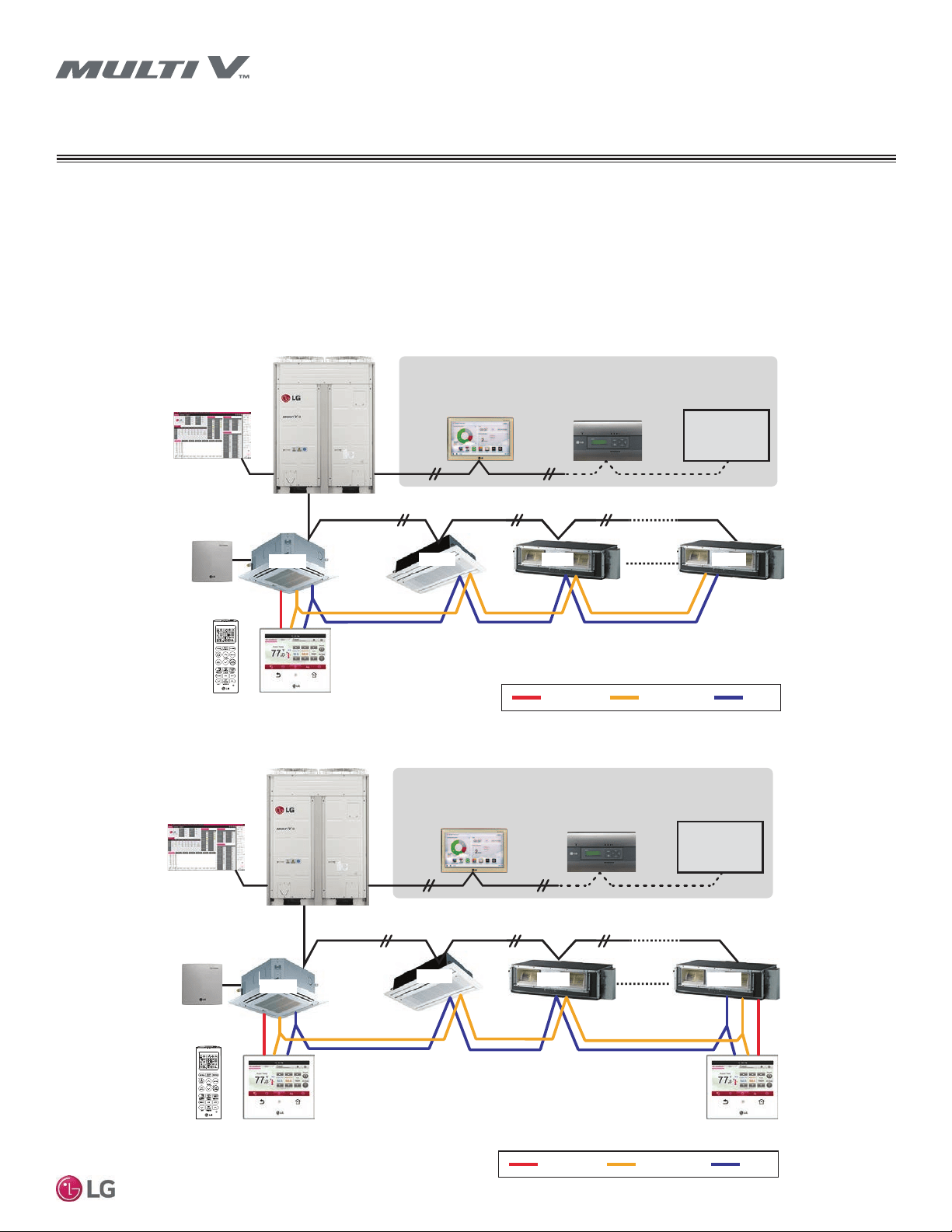
73
Installation Manual
Due to our policy of continuous product innovation, some specifications may change without notification.
©LG Electronics U.S.A., Inc., Englewood Cliffs, NJ. All rights reserved. “LG” is a registered trademark of LG Corp.
CONTROLS SETUP
Slave
Slave
Slave
Master
Slave
Display
Error
Message
▪ Connect Signal and GND lines
between slave indoor units
▪ Do not connect 12V line
between slave indoor units
Display
Error
Message
Master
GNDSignal12V
AC Smart
ACP Bacnet/ACP LON
(Optional)
Other Building
Mgmt System
(Optional)
LGMV
LGAP Network System
Dry
Contact
(Optional)
Figure 53: Group Control - Method 1
Slave Slave
Slave
Display
Error
Message
▪ Connect Signal and GND lines between slave indoor units
▪ Do not connect 12V line between slave indoor units
Master
Master
GNDSignal12V
AC Smart
ACP Bacnet/ACP LON
(Optional)
Other Building
Mgmt System
(Optional)
LGMV
LGAP Network System
Dry
Contact
(Optional)
Figure 54: Group Control - Method 2
Group Control
Figure 53, Figure 54, and Figure 55 show examples of typical control configurations. Figure 53 shows one wired remote controller configured
as a Master to control a group of indoor units. Figure 54 shows two wired remote controllers, one configured as a Master and the other as a
Slave. Figure 55 shows a system with indoor units and fresh air units configured as two groups, each with a Master wired controller. Config-
ure the fresh air units as one group and the standard indoor units as another group. Figure 56 shows both a correct and an incorrect control
configuration for this type of mixed unit system.
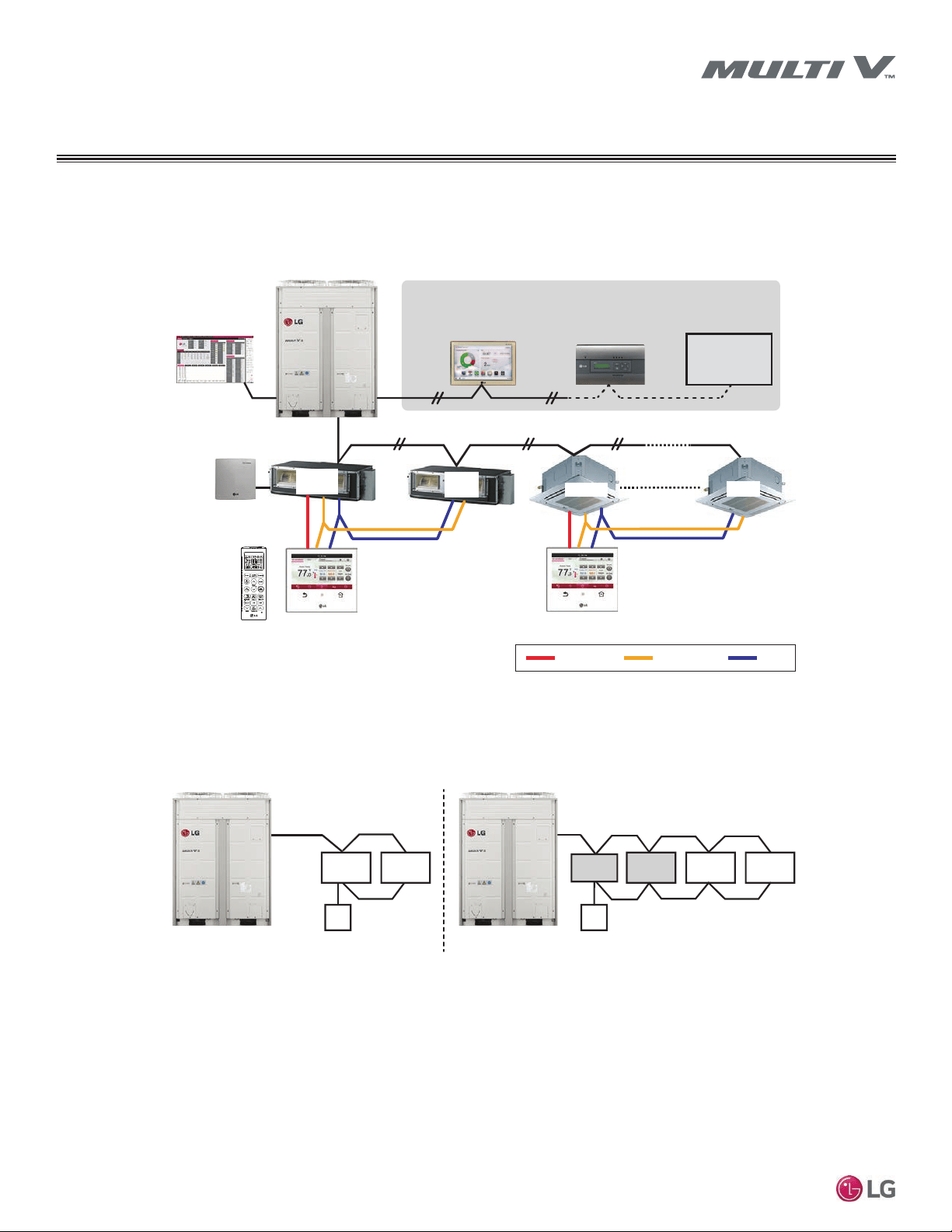
74
Multi V Ducted Indoor Units
Due to our policy of continuous product innovation, some specifications may change without notification.
©LG Electronics U.S.A., Inc., Englewood Cliffs, NJ. All rights reserved. “LG” is a registered trademark of LG Corp.
CONTROLS SETUP
FAU
Master
FAU
Slave
Master
Slave
Master
Master
Display
Error
Message
Display
Error
Message
AC Smart
ACP Bacnet/ACP LON
(Optional)
Other Building
Mgmt System
(Optional)
LGMV
LGAP Network System
▪ Connect Signal and GND
lines to slave indoor units
▪ Do not connect 12V line
to slave indoor units
GNDSignal12V
Dry
Contact
(Optional)
Figure 55: Group Control - Method 3
FAU FAU StandardStandard
FAU: Fresh Air Intake Unit
Standard: Standard Indoor Unit
ZC: Zone Controller
StandardStandard
Correct Control Wiring Incorrect Control Wiring
ZC ZC
Figure 56: Control Wiring with Standard IDU and Fresh Air Unit
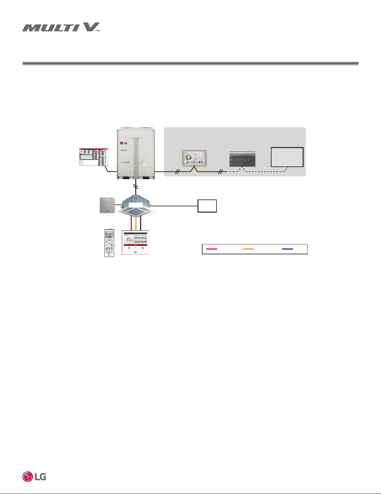
75
Installation Manual
Due to our policy of continuous product innovation, some specifications may change without notification.
©LG Electronics U.S.A., Inc., Englewood Cliffs, NJ. All rights reserved. “LG” is a registered trademark of LG Corp.
CONTROLS SETUP
Remote
Sensor
Display
Error
Message
Master
Master
AC Smart
ACP Bacnet/ACP LON
(Optional)
Other Building
Mgmt System
(Optional)
LGMV
LGAP Network System
GNDSignal12V
Dry
Contact
(Optional)
Figure 57: Remote Control
Remote Control
Figure 57 shows an example of a remote control configuration.
INSTALLATION CHECKLIST
System ID No.: _________________________________________________ Indoor Unit ID.: ____________________________________
Checked by: __________________________________ Date:__________________ Signature: ___________________________________
PAGE 1 of 2
4-Way Cassette Indoor Unit
76
Due to our policy of continuous product innovation, some specifications may change without notification.
©LG Electronics U.S.A., Inc., Englewood Cliffs, NJ. All rights reserved. “LG” is a registered trademark of LG Corp.
Rough-In N/A Not Complete Complete
Packing materials and literature removed from fan discharge.
Airflow direction correct.
Fan wheels spin without obstruction.
Unit is properly supported – mounting bolts tight.
Unit is level (condensate pump installations).
Unit is canted toward gravity drain pan nipple (gravity drain installations only).
Recommended minimum service clearances followed.
Air filter is clean and properly installed.
Does local code require a secondary drain pan under the indoor unit? Is a secondary drain line connected
to the pan?
Ductwork N/A Not Complete Complete
All seams sealed – no air leaks.
High-static models only – minimum external static pressure requirements met.
Ductwork is properly sized considering the available external static pressure rating of the indoor unit fan.
No kinks present in the flexible ductwork. Ductwork is properly supported.
Ductwork balancing dampers have been installed and are correctly adjusted or open.
Grilles and registers are properly sized and installed.
Refrigerant Piping N/A Not Complete Complete
A dry nitrogen purge rate of three (3) psig was maintained during all brazing activity.
PVE refrigerant oil was used as a lubricant on flare fittings (POE type was NOT used).
Field formed pipe flares are 45°.
Flare fittings were properly tightened.
Refrigerant pipe is properly supported to keep lateral pressure off unit connections.
Refrigerant shutoff valves are full port design with integral Schrader port rated for R410A (option).
Shutoff valves have the same internal pipe diameter as the connected pipe (option).
Two shutoff valves were installed; one (1) high pressure liquid, one (1) low pressure vapor (option).
Shutoff valves installed with Schrader port between the indoor unit and the ball of the valve (option).
Condensate System N/A Not Complete Complete
Condensate pipe is properly sized and supported to keep lateral pressure off unit connections.
Condensate pipe horizontal segments are sloped a minimum of 1/4"/100' of pipe away from the indoor unit.
Condensate pipe and drain traps were sized using LG recommendations.
Field-provided condensate line check valve was installed in the condensate pipe riser (option).
Condensate traps were installed on gravity drain pipes (High-Static models only).
Condensate line vertical rise between indoor unit bottom and high point of the line does not exceed 27-1/2".
Condensate pump power has been disconnected (High-Static indoor unit gravity-drain installations only).
Condensate pump riser intersects the building main drain using an inverted trap with connection to the top half
of the drain line with no more of a ±45° of vertical.
If required by local code, is a secondary high level condensate shutoff switch present/wired properly (factory
provided internal high level float switch will shut down cooling operation if high water level in the pan is detected)?
Insulation N/A Not Complete Complete
Additional housing, refrigerant and condensate pipe insulation has been supplemented to prevent sweating
while operating if indoor unit installed in abnormal environmental conditions. (Optional - job condition specific.)
All pipes are independently insulated. All insulation seams and joints are airtight. Insulation is not compressed.
Double layer insulation is provided at pipe supports and wall penetrations.
INSTALLATION CHECKLIST
Installation Manual
System ID No.: _________________________________________________ Indoor Unit ID.: ____________________________________
Checked by: __________________________________ Date:__________________ Signature: ___________________________________
PAGE 2 of 2
77
Due to our policy of continuous product innovation, some specifications may change without notification.
©LG Electronics U.S.A., Inc., Englewood Cliffs, NJ. All rights reserved. “LG” is a registered trademark of LG Corp.
Electrical N/A Not Complete Complete
Power provided is single phase, ±10% of indoor unit nameplate specifications.
Power wires properly sized and protected per NEC and local codes. Indoor unit is properly grounded.
Power and communications conductors are separated by the recommended minimum distance.
Terminal block screws are tight. Power wires are not in contact with terminals 3(A) and / or 4(B). Line voltage
wires have spade connectors installed.
Power wires are properly secured to the control box case to prevent wire tension at the terminal block.
Wires are protected from chaffing at control box and conduit pipe penetrations.
(Optional) Smoke detector is properly installed and wired. New batteries are installed (if applicable).
Low voltage control cables are properly secured to the control panel case. Terminal block screws are tight and
the cable is protected from sharp edges at control box case and conduit openings.
Cables are installed at recommended distances from high voltage and EMF generating equipment.
Outdoor unit / Indoor unit communications cable (terminals 3[A] and 4[B]).
Field provided communications cable is 18-2 stranded and shielded. All terminations are made at the terminal
block. No inline splices or wire caps are present.
Communications cable is plenum rated.
Communications cable shield is tied back and is grounded at only ONE end.
Wall Mounted Zone Controller Communications N/A Not Complete Complete
LG factory provided zone controller stranded, shielded (white jacket) cable was used between the zone
controller(s) and indoor unit(s).
Zone controller cable has not been cut, spliced, or tied together with wire caps. Factory plugs are present.
Cable is securely plugged into the socket on the zone controller or the three screw terminals (controller model
specific); Yellow to “Y”, Red to “R”, and Black to “B”.
Zone controller DIP switches have been adjusted for the application’s space temperature sensing strategy.
Indoor Unit Control Panel N/A Not Complete Complete
Zone controller cable is securely plugged into the CN-REMO socket on the indoor unit circuit board.
If an optional remote temperature sensor was installed, the associated cable is plugged into socket CN-ROOM
(the factory return air thermistor has been unplugged).
Indoor unit DIP switches have been adjusted for application (group control-master/slave; continuous fan
operation; dry contact).
If a gravity drain primary condensate system is used (condensate pipe ONLY connected to the lowest nipple)
the CN-D / Pump plugged has been removed from the socket on the control board (High-Static models only).
All plugs are properly seated in the sockets on the control board.
Power and communications cables are properly restrained and separated.

78
Multi V Ducted Indoor Units
Due to our policy of continuous product innovation, some specifications may change without notification.
©LG Electronics U.S.A., Inc., Englewood Cliffs, NJ. All rights reserved. “LG” is a registered trademark of LG Corp.

79
Installation Manual
Due to our policy of continuous product innovation, some specifications may change without notification.
©LG Electronics U.S.A., Inc., Englewood Cliffs, NJ. All rights reserved. “LG” is a registered trademark of LG Corp.
Who to call for assistance
Freight Damage and Unit Replacements Your LG Manufacturer Representative
Missing Parts Your LG Manufacturer Representative
Freight Damage and Unit Replacements Your LG Manufacturer Representative
Received Wrong Indoor Unit Model Your LG Manufacturer Representative
Installation, Startup, and Commissioning Technical Assistance 1-888-865-3026
For warranty information, visit www.lghvac.com.
IM_MultiV_Ducted_IDU_5_16
Supersedes: IM-MultiV-DuctedIDU-08-14
LG Electronics
Commercial Air Conditioning Division
11405 Old Roswell Road
Alpharetta, Georgia 30009
www.lghvac.com
LG Customer Information Center, Commercial Products
1-888-865-3026 USA
Follow the prompts for commercial A/C products and parts.
20001747 ISO 9001: 2008
LG ELECTRONICS INC.