Owner's Manual
®
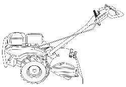
REAR TINE TILLER WITH
COUNTER ROTATING TINES
850 Series
17 Inch Tine Width
Model No.
917.297031
• EspaSol, p. 22
©
This product has a low emission engine which operates
[_ differently from previously built engines. Before start the
you
engine, read and understand this Owner's Manual.
IMPORTANT:
Read and follow all Safety
Rules and Instructions before
operating this equipment.
Sears, Roebuck and Co., Hoffman Estates, IL 60179 U.S.A.
Visit our Craftsman website:www.sears_com/craftsman
SafetyRules...........................................2
Warranty.................................................2
ProductSpecifications .........................4
Assembly/Pre-Operation........................6
Operation...............................................8
Maintenance........................................13
ServiceandAdjustments....................15
Storage.................................................19
Troubleshooting...................................20
IllustratedPartsList.............................42
SearsService........................BackCover
LIMITEDTWOYEARWARRAN"[_ONCRAFTSMANTILLER
For two (2)yearsfrom date of purchase,whenthis CraftsmanTiller is maintained,
lubricated,andtuned up accordingto the operatingand maintenanceinstructionsinthe
owner'smanual,Searswill repairfree of chargeany defectin materialor workmanship.
ThisWarrantydoesnot cover:
• Expendableitemswhichbecomewornduringnormaluse,suchas tines,sparkplugs,
air cleanersand belts.
• Repairsnecessarybecauseof operatorabuseor negligence,includingbent crank-
shaftsandthefailureto maintainthe equipmentaccordingto the instructionscon-
tained in the owner'smanual.
• If thisCraftsmanTiller is usedfor commercialor rentalpurposes,this Warrantyapplies
for onlythirty (30)days fromthe dateof purchase.
Warrantyserviceis availableby returningthecraftsmanpowermowerto the nearest
searsservicecenter/departmentinthe unitedstate&Thiswarrantyappliesonlywhile
this productis in use in the unitedstates.
This Warranty gives you specific legal rights, and you may also have other rights which
vary from state to state,
SEARS, ROEBUCK AND CO., D/817WA, HOFFMAN ESTATES, IL 60179 U,S.A.
IMPORTANT: This cutting machine is capable of amputating hands and feet and throw-
ing objects. Failure to observe the following safety instructions could result in serious
injury or death.
TRAINING
• Read the Owner's Manual carefully. Be
thoroughly familiar with the controls and
the proper use of the equipment, Know
how to stop the unit and disengage the
controls quickly.
• Never allow children to operate the
equipment. Never allow adults to op-
erate the equipment without proper
instruction.
• Keep the area of operation clear of all
persons, particularly small children, and
pets.
PREPARATION
• Thoroughly inspect the area where the
equipment is to be used and remove all
foreign objects.
• Disengage all clutches and shift into
neutral before starting the engine (rec-
to0.
• Do not operate the equipment without
wearing adequate outer garments. Wear
footwear that will improve footing on
slippery surfaces.
• Handle fuel with care; it is highly flam-
mable,
• Use an approved fue! container,
• Never add fuel to a running engine or
hot engine,
• Fill fuel tank outdoors with extreme care.
Never fill fuel tank indoors,
• Replace gasoline cap securely and
clean up spilled fuel before restarting.
2
• Use extension cords and receptacles
as specified by the manufacturer for all
units with electric drive motors or elec-
tric starting motors.
. Never attempt to make any adjustments
while the engine (motor) is running (ex*
cept where specifically recommended
by manufacturer),
OPERATION
• Do not put hands or feet near or under
rotating part&
• Exercise extreme caution when operat-
ing on or crossing gravel drives, walks,
or roads. Stay alert for hidden hazards
or traffic° Do not carry passengers.
• After striking a foreign object, stop the
engine (motor), remove the wire from
the spark plug, thoroughly inspect the
tiller for any damage, and repair the
damage before restarting and operating
the tiller_
• Exercise caution to avoid slipping or fall-
ing,
• If the unit should start to vibrate ab-
normally, stop the engine (motor) and
check immediately for the cause. Vibra-
tion is generally a warning of trouble.
• Stop the engine (motor) when leaving
the operating position.
• Take all possible precautions when leav-
ing the machine unattended. Disengage
the tines, shift into neutral, and stop the
engine.
• Before cleaning, repairing, or inspecting,
shut off the engine and make certain all
moving parts have stopped, Disconnect
the spark plug wire, and keep the wire
away from the plug to prevent accidental
starting. Disconnect the cord on electric
motors.
• Do not run the engine indoors; exhaust
fumes are dangerous.
• Never operate the tiller without proper
guards, plates, or other safety protective
devices in place.
• Keep children and pets away.
• Do not overload the machine capacity
by attempting to till too deep at too fast
a rate,
• Never operate the machine at high
speeds on slippery surfaces, Look be-
hind and use care when backing.
• Never allow bystanders near the unit.
• Use only attachments and accessories
approved by the manufacturer of the
tiller_
• Never operate the tiller without good vis-
ibility or light.
• Be careful when tilling in hard ground,
The tines may catch in the ground and
propel the tiller forward, If this occurs,
let go of the handlebars and do not
restrain the machine.
MAINTENANCE AND STORAGE
• Keep machine, attachments, and ac-
cessories in safe working condition,
• Check shear pins, engine mounting
bolts, and other bolts at frequent inter-
vals for proper tightness to be sure the
equipment is in safe working condition.
• Never store the machine with fuel in the
fuel tank inside a building where ignition
sources are present, such as hot water
and space heaters, clothes dryers, and
the like. Aliow the engine to cool before
storing in any enclosure.
• Always refer to the operator's guide
instructions for important details if the
tiller is to be stored for an extended
period.
_Look for this symbol to point out
important safety precaution& It means
CAUTIONI!I BECOME ALERTII! YOUR
SAFETY IS INVOLVED.
,I(_CAUTION: Always disconnect spark
plug wire and place wire where it cannot
contact spark plug in order to prevent acci-
dental starting when setting up, transport-
ing, adjusting or making repairs.
•OILWARNING. Engine exhaust, some of its
constituents, and certain vehicle compo-
nents contain or emit chemicals known to
the State of California to cause cancer and
birth defects or other reproductive harm.
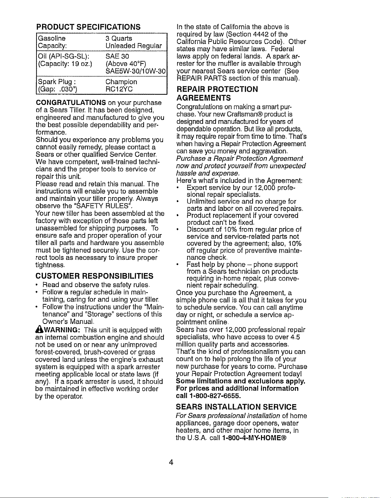
PRODUCT SPECIFICATIONS
Gasoline 3 Quarts
Capacity: Unleaded Regular
Oil (API-SG-SL): SAE 30
(Capacity: 19 oz,) (Above 40°F)
SAE5W-30/10W-30
Spark Plug : Champion
(G ap: ,030") RC 12YC
CONGRATULATIONS on your purchase
of a Sears Tiller. It has been designed,
engineered and manufactured to give you
the best possible dependability and per-
formance,
Should you experience any problems you
cannot easily remedy, ptease contact a
Sears or other qualified Service Center.
We have competent, well-trained techni-
cians and the proper tools to service or
repair this unit.
Please read and retain this manual. The
instructions will enable you to assemble
and maintain your tiller properly. Always
observe the "SAFETY RULES".
Your new tiller has been assembled at the
factory with exception of those parts left
unassembled for shipping purposes. To
ensure safe and proper operation of your
tiller all parts and hardware you assemble
must be tightened securely. Use the cor-
rect tools as necessary to insure proper
tightness_
CUSTOMER RESPONSIBILITIES
• Read and observe the safety rules,
• Foliow a regular schedule in main-
taining, caring for and using your tiller.
• Follow the instructions under the "Main-
tenance" and "Storage" sections of this
Owner's Manual.
_WARNING: This unit is equipped with
an internal combustion engine and should
not be used on or near any unimproved
forest-covered, brush-covered or grass
covered land unless the engine's exhaust
system is equipped with a spark arrester
meeting applicable local or state laws (if
any). If a spark arrester is used, it should
be maintained in effective working order
by the operator.
In the state of California the above is
required by law (Section 4442 of the
California Public Resources Code), Other
states may have similar laws, Federal
laws apply on federal lands. A spark ar-
rester for the muffler is available through
your nearest Sears service center (See
REPAIR PARTS section of this manual).
REPAIR PROTECTION
AGREEMENTS
Congratulations on making a smart pur-
chase. Your new Craftsman® product is
designed and manufactured for years of
dependable operation, But like all products,
it may require repair from time to time. That's
when having a Repair Protection Agreement
can save you money and aggravation,
Purchase a Repair Protection Agreement
now and protect yourseff from unexpected
hassle and expense.
Here's what's included in the Agreement:
• Expert service by our 12,000 profe-
sional repair specialists,
. Unlimited service and no charge for
parts and labor on all covered repairs,
• Product replacement if your covered
product can't be fixed,
• Discount of 10% from regular price of
service and service-related parts not
covered by the agreement; also, 10%
off regular price of preventive mainte-
nance check.
• Fast help by phone- phone support
from a Sears technician on products
requiring in-home repair, plus conve-
nient repair scheduling,
Once you purchase the Agreement, a
simple phone call is all that it takes for you
to schedule service° You can call anytime
day or night, or schedule a service ap-
pointment online
Sears has over 12,000 professional repair
specialists, who have access to over 4.5
million quality parts and accessories.
That's the kind of professionalism you can
count on to help prolong the life of your
new purchase for years to come, Purchase
your Repair Protection Agreement todayl
Some limitations and exclusions apply,
For prices and additional information
call 1-800-827-6655.
SEARS INSTALLATION SERVICE
For Sears professional installation of home
appliances, garage door openers, water
heaters, and other major home items, in
the U,SA. call 1-800-4-MY-HOME®
4
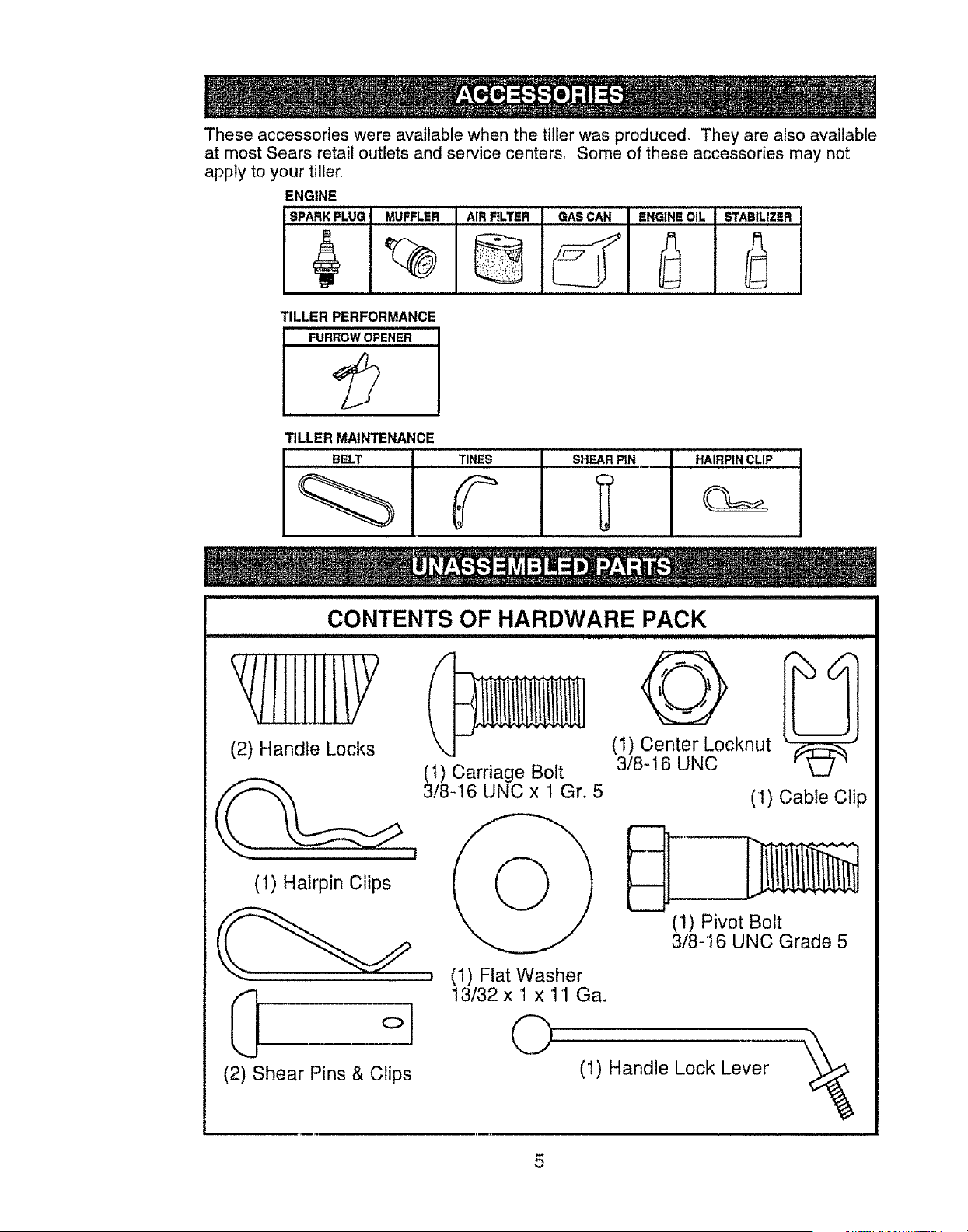
These accessories were available when the tiller was produced, They are also available
at most Sears retail outlets and service centers, Some of these accessories may not
apply to your tiller,
ENGINE
SPARK PLUG
MUFFLER AIR RLTER GAS CAN I ENGINE OIL STABILIZER
TILLER PERFORMANCE
FuRRow OPENER
TILLER MAINTENANCE
BELT TINES SHEAR PIN
I
HAIRPIN cLiP
CONTENTS OF HARDWARE PACK
(2) Handle Locks
!
(1) Hairpin Clips
{2) Shear Pins & C!ips
(I) Carriage Belt
3/8-16 UNC x 1 Gr. 5
O
(1) Center Locknut
3/8-16 UNC
(I) Cable Clip
D
(1) Pivot Bolt
3/8-16 UNC Grade 5
, (1) Flat Washer
13/32 x 1 x 11 Ga.
O' ii) Handle E0ck Lev'er__
Your new tiller has been assembled at the factory with the exception of those parts left
unassembled for shipping purposes,, To ensure safe and proper operation of your tiller
all parts and hardware you assemble must be tightened securely, Use the correct tools
as necessary to insure proper tightness,
TOOLS REQUIRED FOR
ASSEMBLY
A socket wrench set will make assembly
easier. Standard wrench sizes are tisted.
(1) Utility knife
(1) Wire cutter
(1) Tire pressure gauge
(1) Screwdriver
(1) Pair of pliers
(I) 9/16" wrench
OPERATOR'S POSITION
When right or left hand is mentioned in
this manual, it means when you are in the
operating position (standing behind tiller
handles),
FRONT
LEFT
OPERATOR'S
POSITION
RIGHT
UNPACKING CARTON
_kCAUTION: Be careful of exposed sta-
ples when handling or disposing of carton-
ing material.
IMPORTANT: When unpacking and
assembling tiller, be careful of exposed
staples when handling or disposing of
cartoning material
I. While holding handle assembly, cut cable
ties securing handle assembly to top
frame, Let handle assembly rest on tiller.
2. Remove top frame of carton,
3. Slowly ease handle assembly up and
place on top of carton°
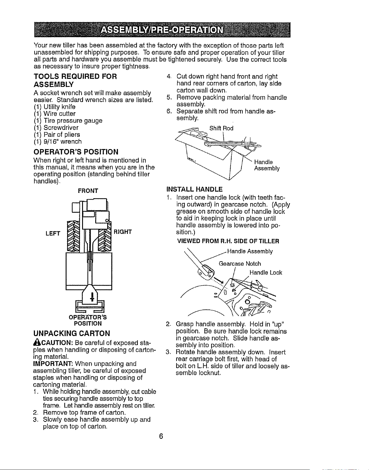
4r Cut down right hand front and right
hand rear corners of carton, lay side
carton wall down,
5, Remove packing material from handle
assembly,
6. Separate shift rod from handle as-
sembly,
Shift Rod
Handle
Assembly
INSTALL HANDLE
1, Insert one handle lock (with teeth fac-
ing outward) in gearcase notch. (Apply
grease on smooth side of handle lock
to aid in keeping lock in ptace until
handle assembly is lowered into po-
sition,)
VIEWED FROM R.H. SIDE OF TILLER
- Handle Assembly
Gearcase Notch
ndle Lock
2. Grasp handle assembly. Hold in "up"
position° Be sure handle lock remains
in gearcase notch. Slide handle as-
sembly into position_
3. Rotate handle assembly down. Insert
rear carriage bolt first, with head of
bolt on L.Ho side of tiller and loosely as-
semble Iocknut,
6
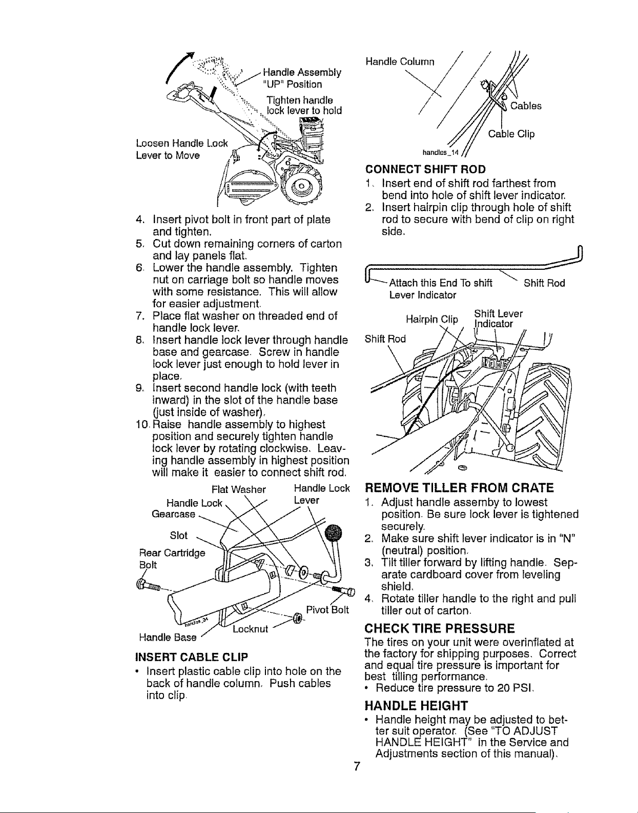
"UP" Position
• _... Tighten handle
, '"'.. lock Iever to hold
Handle Column / /
/
/ Cables
Loosen Handle Lock
Lever to Move
4. Insert pivot bolt in front part of plate
and tighten,
5, Cut down remaining corners of carton
and lay panels flat,
6- Lower the handle assembly. Tighten
nut on carriage bolt so handle moves
with some resistance. This wilt allow
for easier adjustment,
7. Place flat washer on threaded end of
handle lock lever,
8, Insert handle lock lever through handle
base and gearcase. Screw in handle
lock lever just enough to hold lever in
place,
9, Insert second handle lock (with teeth
inward) in the slot of the handle base
(just inside of washer),
10_ Raise handle assembly to highest
position and securely tighten handle
lock lever by rotating clockwise, Leav-
ing handle assembly in highest position
will make it easier to connect shift rod_
Flat Washer Handle Lock
Handle Lock Lever
Gearcase
Slot
Rear Cartridge
Bolt
Handle Base
Locknut ""i1_-Piv°t Bolt
INSERT CABLE CLIP
• Insert plastic cable clip into hole on the
back of handle column, Push cables
into clip.
Cable Clip
handEes_14
CONNECT SHIFT ROD
1, Insert end of shift rod farthest from
bend into hole of shift lever indicator.
2, Insert hairpin clip through hole of shift
rod to secure with bend of clip on right
side,
('L'_Attach this End To shift
Lever Indicator
Shift Rod
Shift Lever
Hairpin ndicator
Shift Rod
REMOVE TILLER FROM CRATE
1_ Adjust handle assemby to lowest
position. Be sure lock lever is tightened
securely.
2, Make sure shift lever indicator is in "N"
(neutral) position,
3. Tilt tiller forward by lifting handle. Sep-
arate cardboard cover from leveling
shield,
4, Rotate tiller handle to the right and pull
tiller out of carton.
CHECK TIRE PRESSURE
The tires on your unit were overinflated at
the factory for shipping purposes, Correct
and equal tire pressure is important for
best tilling performance,
. Reduce tire pressure to 20 PSI,
HANDLE HEIGHT
• Handle height may be adjusted to bet-
ter suit operator, (See "TO ADJUST
HANDLE HEIGHT" in the Service and
Adjustments section of this manual),
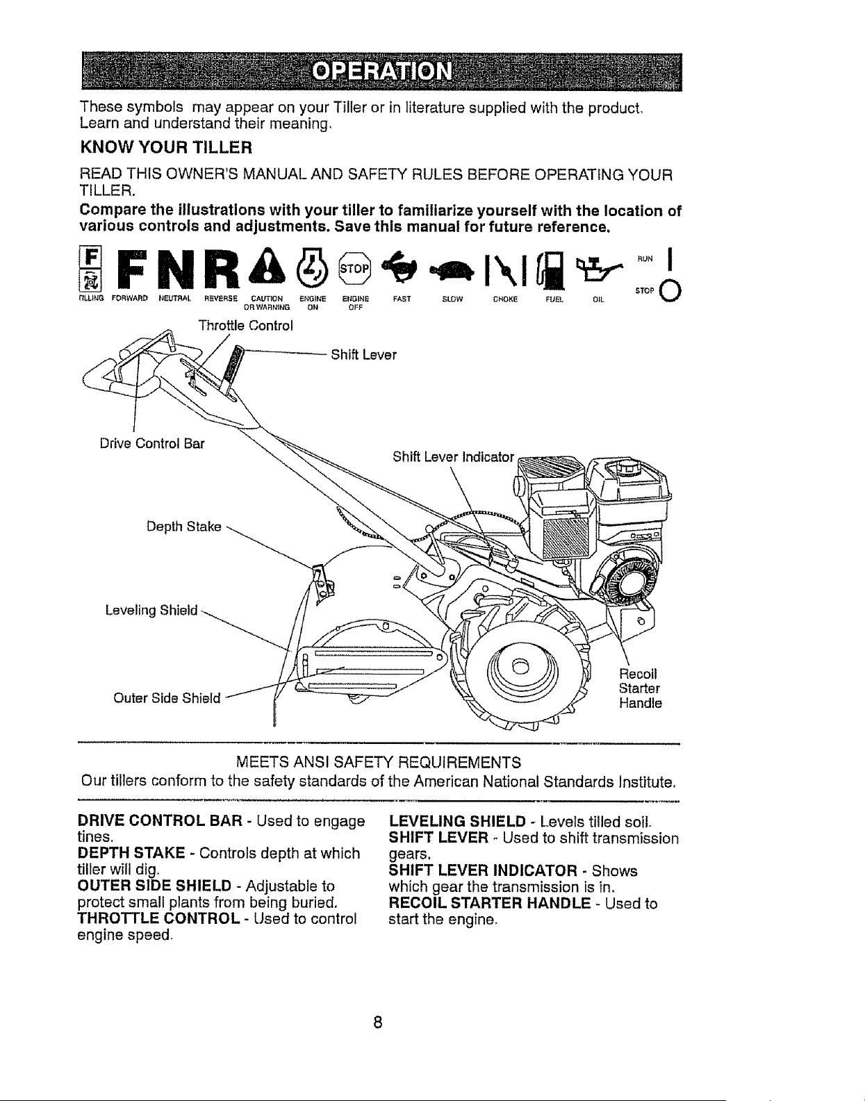
Thesesymbols mayappearon yourTilleror in literaturesuppliedwith the product,
Learnand understandtheir meaning,
KNOW YOUR TILLER
READ THIS OWNER'S MANUAL AND SAFETY RULES BEFORE OPERATING YOUR
TILLER.
Compare the illustrations with your tiller to familiarize yourself with the location of
various controls and adjustments. Save this manual for future reference,
tILLING F_WARD NEUTRAL R_VERSE CALr'i'ION ENGbNE ENGINE FAST SLOW CNOKI_ FUEL OIL STOP V
OR WARNING O1_ OFF
Throttle Control
Shift Lever
Drive Control Bar
Shift Lever Indicator
Depth Stake
Leveling
Outer Side Shield
Recoil
Starter
Handle
MEETS ANSI SAFETY REQUIREMENTS
Our tiIlers conform to the safety standards of the American National Standards Institute,
DRIVE CONTROL BAR - Used to engage
tines.
DEPTH STAKE - Controls depth at which
tiller will dig,
OUTER SIDE SHIELD - Adjustable to
protect small plants from being buried,
THROTTLE CONTROL - Used to control
engine speed.
LEVELING SHIELD -Levets tilled soil,
SHIFT LEVER - Used to shift transmission
gears.
SHIFT LEVER INDICATOR - Shows
which gear the transmission is in,
RECOIL STARTER HANDLE - Used to
start the engine,
8
The operation of any tiller can result in foreign objects thrown into the eyes,
which can result in severe eye damage, Always wear safety glasses or eye
shields before starting your tiller and while tilling. We recommend a wide vi-
sion safety mask over spectacles or standard safety glasses.
HOW TO USE YOUR TILLER
Know how to operate all controls before
adding fuel and oil or attempting to start
engine.
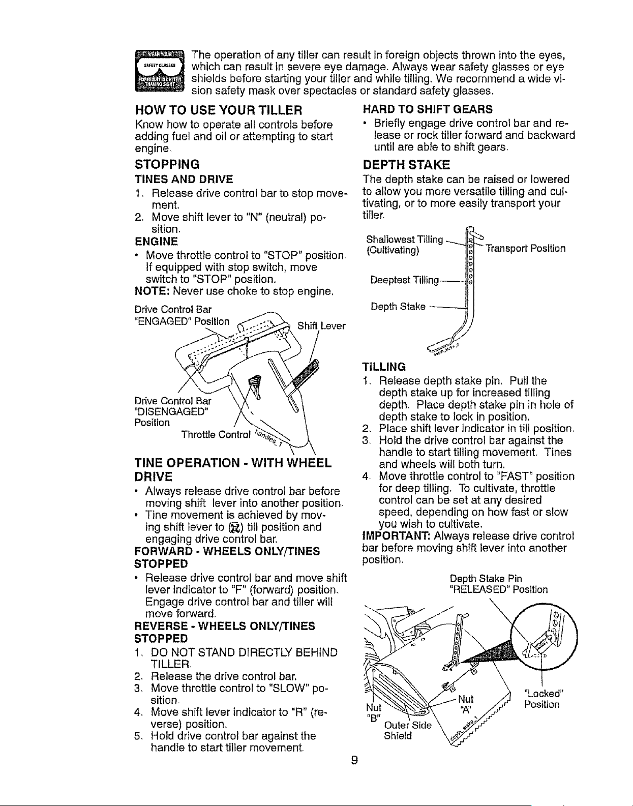
STOPPING
TINES AND DRIVE
1. Release drive control bar to stop move-
ment,
2+ Move shift lever to "N" (neutral) po+
sition,
ENGINE
• Move throttfe control to "STOP" position
If equipped with stop switch, move
switch to "STOP" position.
NOTE: Never use choke to stop engine,
Drive Control Bar
"ENGAGED" Position
Shift Lever
Drive Control Bar
"DISENGAGED"
Position
Throttle Control
TINE OPERATION - WITH WHEEL
DRIVE
• Always release drive control bar before
moving shift lever into another position.
• Tine movement is achieved by mov-
ing shift lever to (_) till position and
engaging drive control bar.
FORWARD - WHEELS ONLY/TINES
STOPPED
• Release drive control bar and move shift
lever indicator to "F" (forward) position.
Engage drive control bar and tiller will
move forward,
REVERSE - WHEELS ONLY!TINES
STOPPED
1_ DO NOT STAND DIRECTLY BEHIND
TILLER,
2. Release the drive control bar,
3, Move throttle control to "SLOW" po-
sition+
4, Move shift lever indicator to "R" (re-
verse) position+
5. Hold drive control bar against the
handle to start tiller movement,
9
HARD TO SHIFT GEARS
• Briefly engage drive control bar and re-
lease or rock tiller forward and backward
until are able to shift gears.
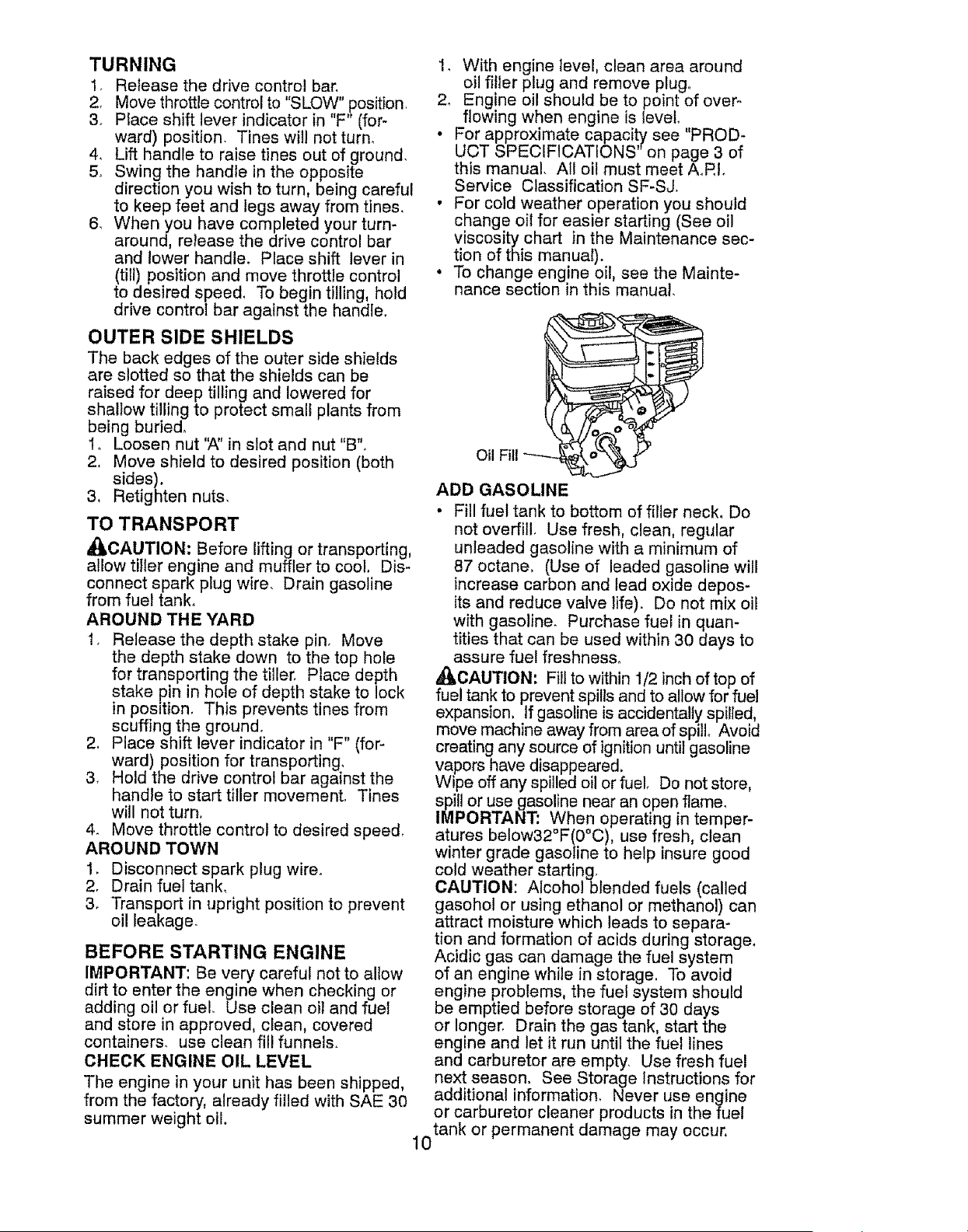
DEPTH STAKE
The depth stake can be raised or lowered
to allow you more versatile tilling and cul-
tivating, or to more easily transport your
tiller_
Shallowest Tilling
(Cultivating)
Deeptest Tilling_
Depth Stake --------
"_Transport Position
TILLING
1, Release depth stake pin+ Pull the
depth stake up for increased tiliing
depth, Place depth stake pin in hole of
depth stake to lock in position,
2. Place shift lever indicator in till position,
3+ Hold the drive control bar against the
handle to start tilling movement. Tines
and wheels wil! both turn,
4. Move throttle control to "FAST" position
for deep tilling, To cultivate, throttle
control can be set at any desired
speed, depending on how fast or slow
you wish to cultivate,
IMPORTANT: Always release drive control
bar before moving shift lever into another
position,
Depth Stake Pin
"RELEASED" Position
Outer Side
Shield
"Locked"
Position
TURNING
1. Release the drive control bar.
2_ Move throttle control to "SLOW" ,position,
& Place shift lever indicator in F (for-
ward) position. Tines will not turn,
4_ Lift handle to raise tines out of ground,
5, Swing the handle in the opposite
direction you wish to turn, being careful
to keep feet and legs away from tines,
& Whenyou have completed your turn-
around, release the drive control bar
and lower handle. Place shift lever in
(till) position and move throttle control
to desired speed, To begin tilling, hold
drive control bar against the handle.
OUTER SIDE SHIELDS
The back edges of the outer side shields
are slotted so that the shields can be
raised for deep tilling and lowered for
shallow tilling to protect small plants from
being buried,
Io Loosen nut 'A" in slot and nut "B",
2. Move shield to desired position (both
sides).
3. Retighten nuts,
TO TRANSPORT
all'CAUTION: Before lifting or transporting,
allow tiller engine and muffler to cool, Dis-
connect spark plug wire. Drain gasoline
from fuel tank,
AROUND THE YARD
1. Release the depth stake pin, Move
the depth stake down to the top hole
for transporting the tiller. Place depth
stake pin in hole of depth stake to lock
in position, This prevents tines from
scuffing the ground.
2, Place shift lever indicator in "F" (for-
ward) position for transporting,
3. Hold the drive control bar against the
handle to start tiller movement, Tines
will not turn,
4. Move throttle control to desired speed,
AROUND TOWN
1. Disconnect spark plug wire.
2. Drain fuel tank_
3. Transport in upright position to prevent
oil leakage.
BEFORE STARTING ENGINE
IMPORTANT: Be very careful not to allow
dirt to enter the engine when checking or
adding oil or fuel, Use clean oil and fuel
and store in approved, clean, covered
containers, use clean fill funnels.
CHECK ENGINE OIL LEVEL
The engine in your unit has been shipped,
from the factory, already filled with SAE 30
summer weight oil.
1, With engine level, clean area around
oil filler plug and remove plugo
2_ Engine oil should be to point of over-
flowing when engine is level.
• For approximate capacity see "PROD-
UCT SPECIFICATIONS on page 3 of
this manual. All oil must meet A.Rt.
Service Classification SF-SJ.
• For cold weather operation you should
change oil for easier starting (See oil
viscosity chart in the Maintenance sec-
tion of this manual).
° To change engine oil. see the Mainte-
nance section in this manual.
Oil
ADD GASOLINE
• Fill fuel tank to bottom of filler neck, Do
not overfill, Use fresh, clean, regular
unleaded gasoline with a minimum of
87 octane. (Use of leaded gasoline will
increase carbon and lead oxide depos-
its and reduce valve life). Do not mix oil
with gasoline, Purchase fuel in quan-
tities that can be used within 30 days to
assure fuel freshness.
_CAUTION: Fill to within 1/2 inch of top of
fuel tank to prevent spills and to allow for fuel
expansion, If gasoline is accidentally spilled,
move machine away from area of spill, Avoid
creating any source of ignition until gasoline
vapors have disappeared.
Wipe off any spilled oil or fuel, Do not store.
spill or use gasoline near an open flame_
IMPORTANT: V_hen operating in temper-
atures below32 F(0 C), use fresh, clean
winter grade gasoline to help insure good
cold weather starting
CAUTION: Alcoholbtended fuels (called
gasohol or using ethanol or methanol) can
attract moisture which leads to separa-
tion and formation of acids during storage,
Acidic gas can damage the fuel system
of an engine while in storage. To avoid
engine problems, the fuel system should
be emptied before storage of 30 days
or longer, Drain the gas tank. start the
engine and let it run until the fuel lines
and carburetor are empty, Use fresh fuel
next season. See Storage Instructions for
additional information. Never use engine
or carburetor cleaner products in the fuel
tank or permanent damage may occur,
10
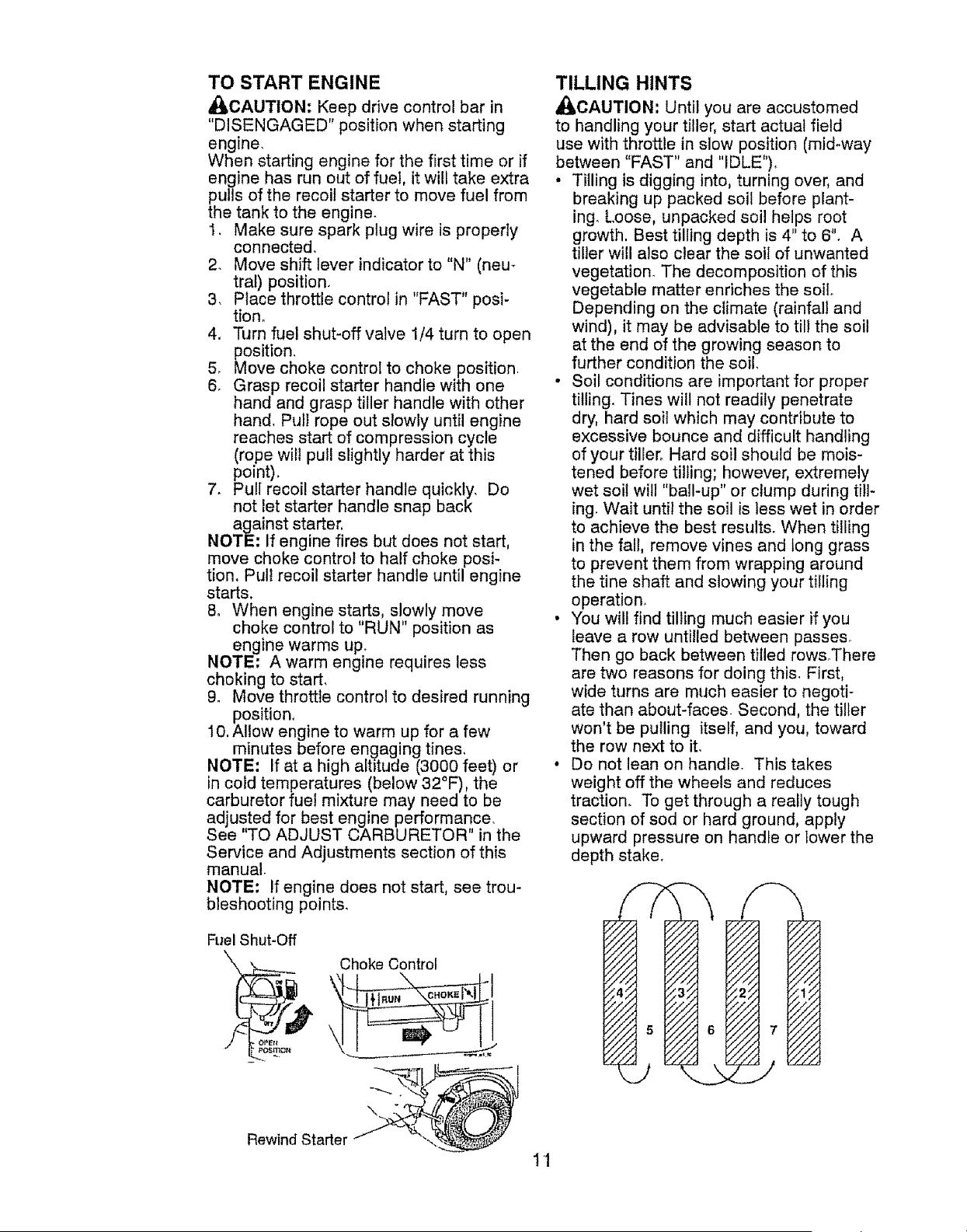
TO START ENGINE
_CAUTION: Keep drive control bar in
"DISENGAGED" position when starting
engine.
When starting engine for the first time or if
engine has run out of fuel, it will take extra
pulls of the recoil starter to move fuel from
the tank to the engine.
1, Make sure spark plug wire is properly
connecte&
2_ Move shift lever indicator to "N" (neu-
tral) position,
3, Place throttle control in "FAST" posi-
tion_
4, Turn fuel shut-off valve 1/4 turn to open
position,
5, Move choke control to choke position.
6, Grasp recoil starter handle with one
hand and grasp tiller handle with other
hand. Pull rope out slowly until engine
reaches start of compression cycle
(rope will pull slightly harder at this
point),
7. Pull recoil starter handle quickly, Do
not let starter handle snap back
against starter,
NOTE; if engine fires but does not start,
move choke control to half choke posi-
tion, Pull recoil starter handle until engine
starts.
8, When engine starts, slowly move
choke control to "RUN" position as
engine warms up.
NOTE: A warm engine requires less
choking to start,
9. Move throttle control to desired running
position,
10, Allow engine to warm up for a few
minutes before engaging tines,
NOTE: If at a high aJt_"tude (3000 feet) or
in cold temperatures (below 32°F), the
carburetor fuel mixture may need to be
adjusted for best engine performance,
See "TO ADJUST CARBURETOR" in the
Service and Adjustments section of this
manual.
NOTE: If engine does not start, see trou-
bleshooting points,
TILLING HINTS
_IbCAUTION: Until you are accustomed
to handling your tiller, start actual field
use with throttle in slow position (mid-way
between "FAST" and "IDLE").
• Tilling is digging into, turning over, and
breaking up packed soil before plant-
ing_ Loose, unpacked soil helps root
growth. Best tilling depth is 4" to 6". A
tiller will also clear the soil of unwanted
vegetation_ The decomposition of this
vegetable matter enriches the soil.
Depending on the climate (rainfall and
wind), it may be advisable to till the soil
at the end of the growing season to
further condition the soil
• Soil conditions are important for proper
titling. Tines will not readily penetrate
dry, hard soil which may contribute to
excessive bounce and difficult handling
of your tiller_ Hard soil should be mois-
tened before tilling; however, extremely
wet soil will "ball-up" or clump during titl-
ing. Wait until the soil is less wet in order
to achieve the best results. When tilling
in the fall, remove vines and long grass
to prevent them from wrapping around
the tine shaft and slowing your tilling
operation.
• You will find tilling much easier if you
leave a row untilled between passes°
Then go back between tilled rows.There
are two reasons for doing this. First,
wide turns are much easier to negoti-
ate than about-faces. Second, the tiller
won't be pulling itself, and you, toward
the row next to it.
• Do not lean on handle. This takes
weight off the wheels and reduces
traction° To get through a really tough
section of sod or hard ground, apply
upward pressure on handle or Iower the
depth stake.
Fuel Shut-Off
Rewind Starter
Choke Control
11
CULTIVATING
Cultivating is destroying the weeds beo
tween rows to prevent them from robbing
nourishment and moisture from the plants,
At the same time, breaking up the upper
layer of soil crust will help retain moisture
in the soil. Best digging depth is I" to 3"
(2.5-7.5 cm),. Lower the outer side shields
to protect small plants from being buried,
• Cultivate up and down the rows at a
speed which will allow tines to uproot
weeds and leave the ground in rough
condition, promoting no further growth
of weeds and grass.
TINE SHEAR PINS
The tine assemblies on your tiller are
secured to the tine shaft with shear pins
(See "TINE REPLACEMENT" in the
Service and Adjustments section of this
manual).
If the tiller is unusually overloaded or
jammed, the shear pins are designed to
break before internal damage occurs to
the transmission.
• If shear pin(s) break, replace only with
those shown in the Repair Parts section
of this manual,
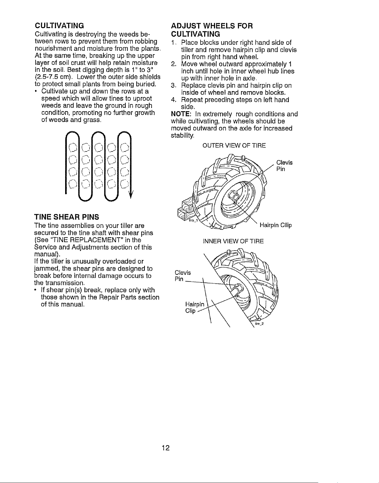
ADJUST WHEELS FOR
CULTIVATING
1, Place blocks under right hand side of
tiller and remove hairpin clip and clevis
pin from right hand wheel.
2. Move wheel outward approximately 1
inch until hole in inner wheel hub lines
up with inner hole in axle.
3_ Replace clevis pin and hairpin clip on
inside of wheel and remove blocks.
4. Repeat preceding steps on left hand
side,
NOTE: In extremely rough conditions and
while cultivating, the wheels should be
moved outward on the axle for increased
stability.
OUTER VIEW OF TIRE
Clevis
Pin
Hairpin Ctlip
INNER VIEW OF TIRE
Clevis
Pin
Hairpin
Cli
12
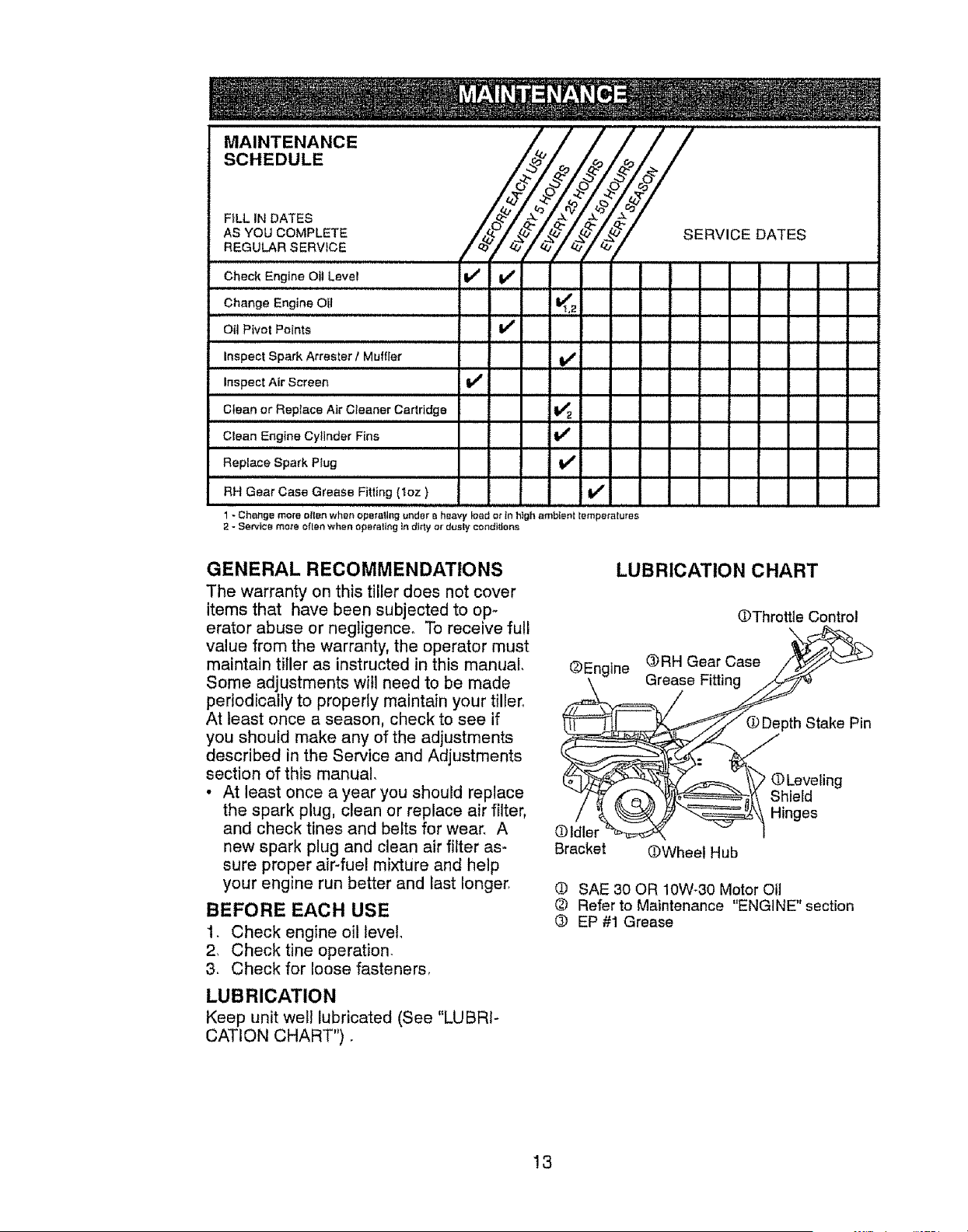
MAINTENANCE
SCHEDULE
FtLL IN DATES
AS YOU COMPLETE
REGULAR SERVICE Z ZCY °'T S
Check Engine Oit Level !_ V'
Change Engine Oil I_t,_
Oit Pivot Points V'
Inspect Spark Attester t Muffler V'
Inspect Air Screen I_
Clean or Replace Air Cleaner Cartridge I_ z
Clean Engfne Cylinder Fins V*
Replace Spark Plug
RH Gear Case Grease Fitting (!oz)
1- Change more ellen when operallng ur_det a heavy load o_ in high ambient temperatures
2 - Sarvtca mote oflea when operating In dkty or dusty condt_ons
GENERAL RECOMMENDATIONS
The warranty on this tiller does not cover
items that have been subjected to op-
erator abuse or negligence, To receive full
value from the warranty, the operator must
maintain tiller as instructed in this manual,
Some adjustments will need to be made
periodically to properly maintain your tiller_
At least once a season, check to see if
you should make any of the adjustments
described in the Service and Adjustments
section of this manual.
• At least once a year you should replace
the spark plug, clean or replace air filter,
and check tines and belts for wear, A
new spark plug and clean air filter as-
sure proper air-fuel mixture and help
your engine run better and last longer.
BEFORE EACH USE
1. Check engine oil level
2, Check tine operation.
3. Check for loose fasteners,
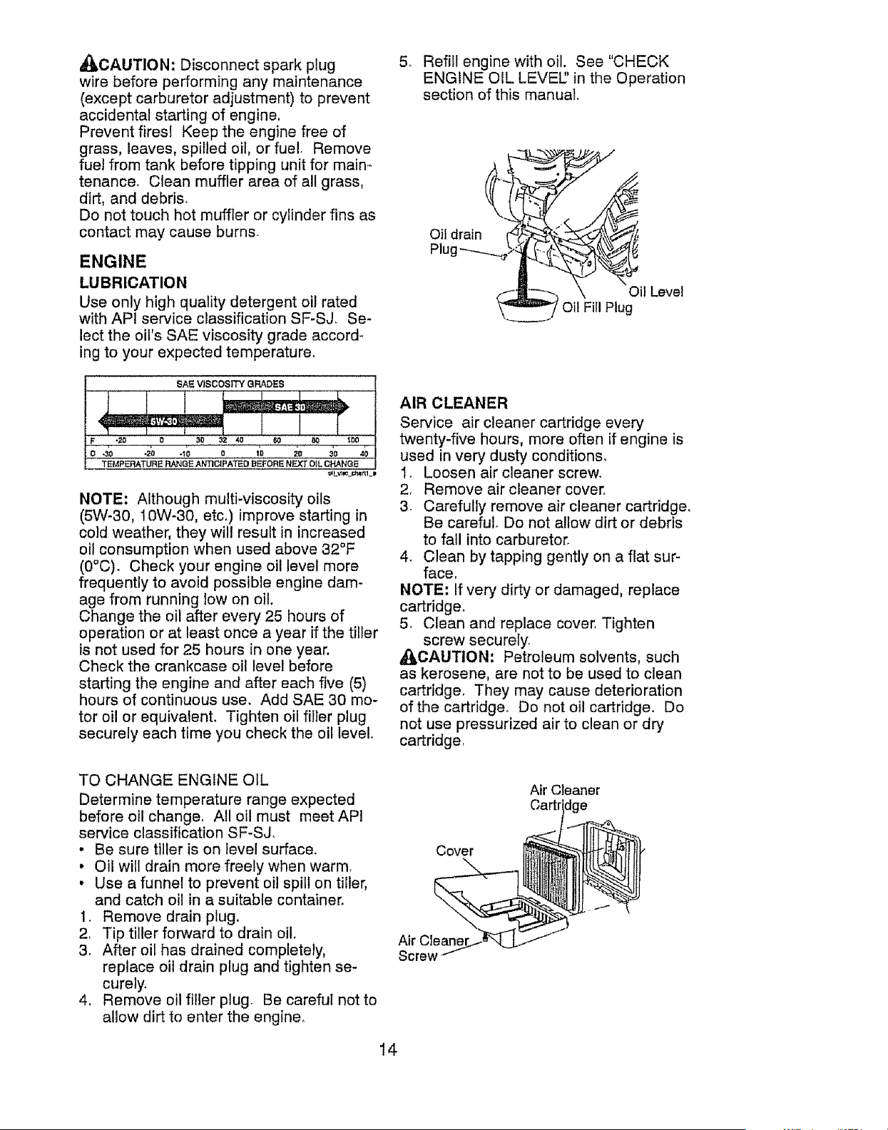
LUBRICATION
Keep unit well lubricated (See "LUBRI-
CATION CHART"),
LUBRICATION CHART
OThrottle Contro!
_En-tne ®RH Gear Case _._:_
pth Stake Pin
/ Hioge
Oldler %_ v I
Bracket (bWheel Hub
O SAE 30 OR 10W-30 Motor Oil
@ Refer to Maintenance "ENGINE" section
® EP #1 Grease
!3
_CAUTION: Disconnect spark plug
wire before performing any maintenance
(except carburetor adjustment) to prevent
accidental starting of engine,
Prevent fires! Keep the engine free of
grass, leaves, spilled oil, or fue!. Remove
fuel from tank before tipping unit for main-
tenance. Clean muffler area of all grass,
dirt, and debris,
Do not touch hot muffler or cylinder fins as
contact may cause burns.
ENGINE
LUBRICATION
Use only high quality detergent oil rated
with API service classification SF-SJ, Se-
lect the oil's SAE viscosity grade accord-
ing to your expected temperature.
NOTE: Although multi-viscosity oils
(5W-30, 10W-30, etc,) improve starting in
cold weather, they will result in increased
oil consumption when used above 32°F
(0°C). Check your engine oil level more
frequently to avoid possible engine dam-
age from running low on oil.
Change the oil after every 25 hours of
operation or at least once a year if the tiller
is not used for 25 hours in one year.
Check the crankcase oil level before
starting the engine and after each five (5)
hours of continuous use. Add SAE 30 mo-
tor oil or equivalent. Tighten oil filler plug
securely each time you check the oil level.
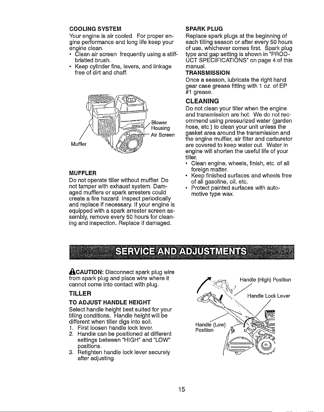
5_ Refill engine with oil, See "CHECK
ENGINE OIL LEVEL' in the Operation
section of this manual
Oil drain _ " (_
Oil FEllPlug
AIR CLEANER
Service air cleaner cartridge every
twenty-five hours, more often if engine is
used in very dusty conditions,
1. Loosen air cleaner screw.
2. Remove air cleaner cover,
3. Carefully remove air cleaner cartridge°
Be careful, Do not allow dirt or debris
to fall into carburetor,
4. Clean by tapping gently on a flat sur-
face,
NOTE: If very dirty or damaged, replace
cartridge_
5, Clean and replace cover. Tighten
screw securely.
_CAUTION: Petroleum solvents, such
as kerosene, are not to be used to clean
cartridge. They may cause deterioration
of the cartridge. Do not oil cartridge. Do
not use pressurized air to clean or dry
cartridge,
TO CHANGE ENGINE OIL
Determine temperature range expected
before oil change. All oil must meet AP!
service classification SF-SJ,
• Be sure tiller is on level surface.
• Oil will drain more freely when warm,
• Use a funnel to prevent oil spill on tiller,
and catch oil in a suitable container.
1, Remove drain plug,
2, Tip tiller forward to drain oil.
3, After oil has drained completely,
replace oil drain plug and tighten se-
curely,
4, Remove oil filler plug. Be careful not to
allow dirt to enter the engine,
Cover
Air Cleane
Screw
Atr Cleaner
:lge
14
COOLING SYSTEM
Your engine is air cooled_ For proper en-
gine performance and long life keep your
engine clean.
• Clean air screen frequently using a stiff-
bristled brush.
• Keep cylinder fins, levers, and linkage
free of dirt and chaff.
Muffler
Housing
Screen
MUFFLER
Do not operate tiller without muffler_ Do
not tamper with exhaust system. Dam-
aged mufflers or spark arresters could
create a fire hazard_ Inspect periodically
and replace if necessary. If your engine is
equipped with a spark arrester screen as-
sembly, remove every 50 hours for clean-
ing and inspection, Replace if damaged.
SPARK PLUG
Replace spark plugs at the beginning of
each tilling season or after every 50 hours
of use, whichever comes first. Spark plug
type and gap setting is shown in "PROD-
UCT SPECIFICATIONS" on page 4 of this
manual,
TRANSMISSION
Once a season, lubricate the right hand
gear case grease fitting with 1 oz. of EP
#1 grease.
CLEANING
Do not clean your tiller when the engine
and transmission are hot. We do not rec-
ommend using pressurized water (garden
hose, etc.) to clean your unit unless the
gasket area around the transmission and
the engine muffIer, air filter and carburetor
are covered to keep water out. Water in
engine will shorten the useful life of your
tiller.
• Clean engine, wheels, finish, etc. of all
foreign matter.
• Keep finished surfaces and wheels free
of all gasoline, oil, etc.
• Protect painted surfaces with auto-
motive type wax.
A_,LCAUTION: Disconnect spark plug wire
from spark plug and place wire where it
cannot come into contact with plug.
TILLER
TO ADJUST HANDLE HEIGHT
Select handle height best suited for your
tilling conditions. Handle height will be
different when tiller digs into soil,
1, First loosen handie lock lever,
2, Handle can be positioned at different
settings between "HIGH" and "LOW"
positions,
3, Retighten handle lock lever securely
after adjusting
Handle (Low)
Position
Handle (High) Position
Handle Lock Lever
t5
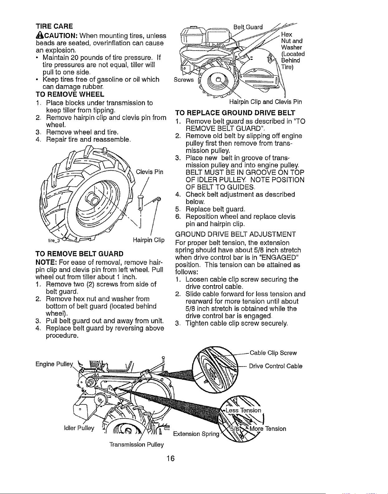
TIRE CARE
,_CAUTION: When mounting tires, unless
beads are seated, overinflation can cause
an explosion,
• Maintain 20 pounds of tire pressure, If
tire pressures are not equal, tiller will
pull to one side,
• Keep tires free of gasoline or oil which
can damage rubber.
TO REMOVE WHEEL
I. Place blocks under transmission to
keep tiller from tipping_
2. Remove hairpin clip and clevis pin from
wheel°
3_ Remove wheel and tire.
4. Repair tire and reassemble.
life Hairpin Clip
TO REMOVE BELT GUARD
NOTE: For ease of removal, remove hair-
pin clip and clevis pin from left wheel. Pull
wheel out from tiller about I inch.
1. Remove two (2) screws from side of
belt guard,
2, Remove hex nut and washer from
bottom of belt guard (located behind
wheel)°
3. Pull belt guard out and away from unit°
4. Replace belt guard by reversing above
procedure,
Engine Pulley\
_.Guard
_)_./_... Washer
ffC_k_ j_. (Located
_-_- _. Behind
S _ire)
\ I
Hairpin Clip and Clevis Pin
TO REPLACE GROUND DRIVE BELT
1, Remove belt guard as described in "TO
REMOVE BELT GUARD",
2. Remove old belt by slipping off engine
pulley first then remove from trans-
mission pulley.
3. Place new belt in groove of trans-
mission pulley and into engine pulley,
BELT MUST BE IN GROOVE ON TOP
OF IDLER PULLEY NOTE POSITION
OF BELT TO GUIDES
4, Check belt adjustment as described
betow.
5, Replace belt guard.
6, Reposition wheel and replace clevis
pin and hairpin clip.
GROUND DRIVE BELT ADJUSTMENT
For proper belt tension, the extension
spring should have about 5/8 inch stretch
when drive control bar is in "ENGAGED"
position. This tension can be attained as
follows:
1, Loosen cable clip screw securing the
drive control cable,
2. Slide cable forward for less tension and
rearward for more tension until about
5/8 inch stretch is obtained while the
drive control bar is engaged
3_ Tighten cable clip screw securely,
Clip Screw
Drive Control Cable
,Less Tension
Idler Pulley
Extension Sprin!
Transmission Pulley
More Tension
16
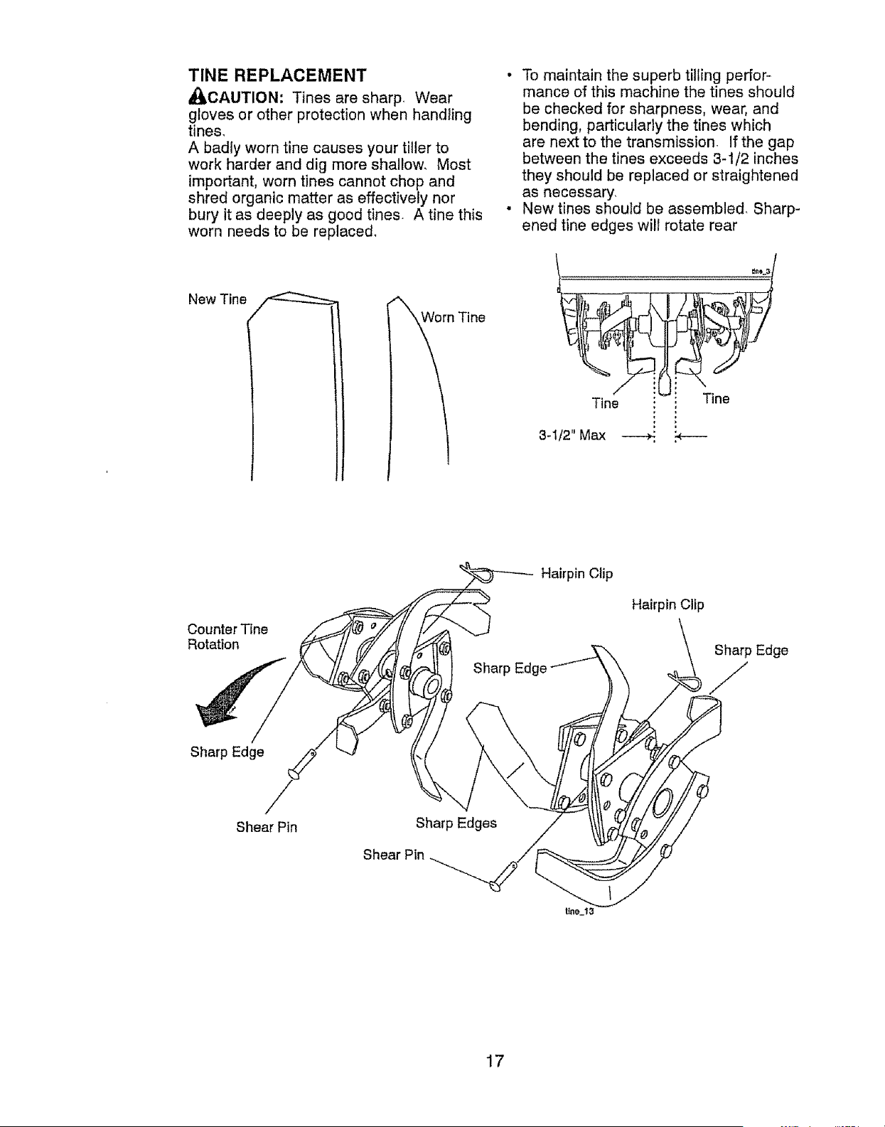
TINE REPLACEMENT
_CAUTION: Tines are sharp. Wear
gloves or other protection when handting
tines,
A badly worn tine causes your tiller to
work harder and dig more shallow, Most
important, worn tines cannot chop and
shred organic matter as effectively nor
bury it as deeply as good tines. A tine this
worn needs to be replaced,
New Tine
'_irn Tine
• To maintain the superb tilling perfor.-
mance of this machine the tines should
be checked for sharpness, wear, and
bending, particularly the tines which
are next to the transmission. If the gap
between the tines exceeds 3-1/2 inches
they should be replaced or straightened
as necessary.
• New tines should be assembled. Sharp-
ened tine edges will rotate rear
Counter Tine
Rotation
Hairpin Clip
Hairpin Clip
Sharp Edge
J
/
Sharp Edge
Shear Pin
Sharp Edges
Shear Pin
ttne_13
17
ENGINE
Maintenance, repair, or replacement of
the emission control devices and systems,
which are being done at the customers ex-
pense, may be performed by any non-road
engine repair establishment or individual,
Warranty repairs must be performed by an
authorized engine manufacturer's service
outlet_
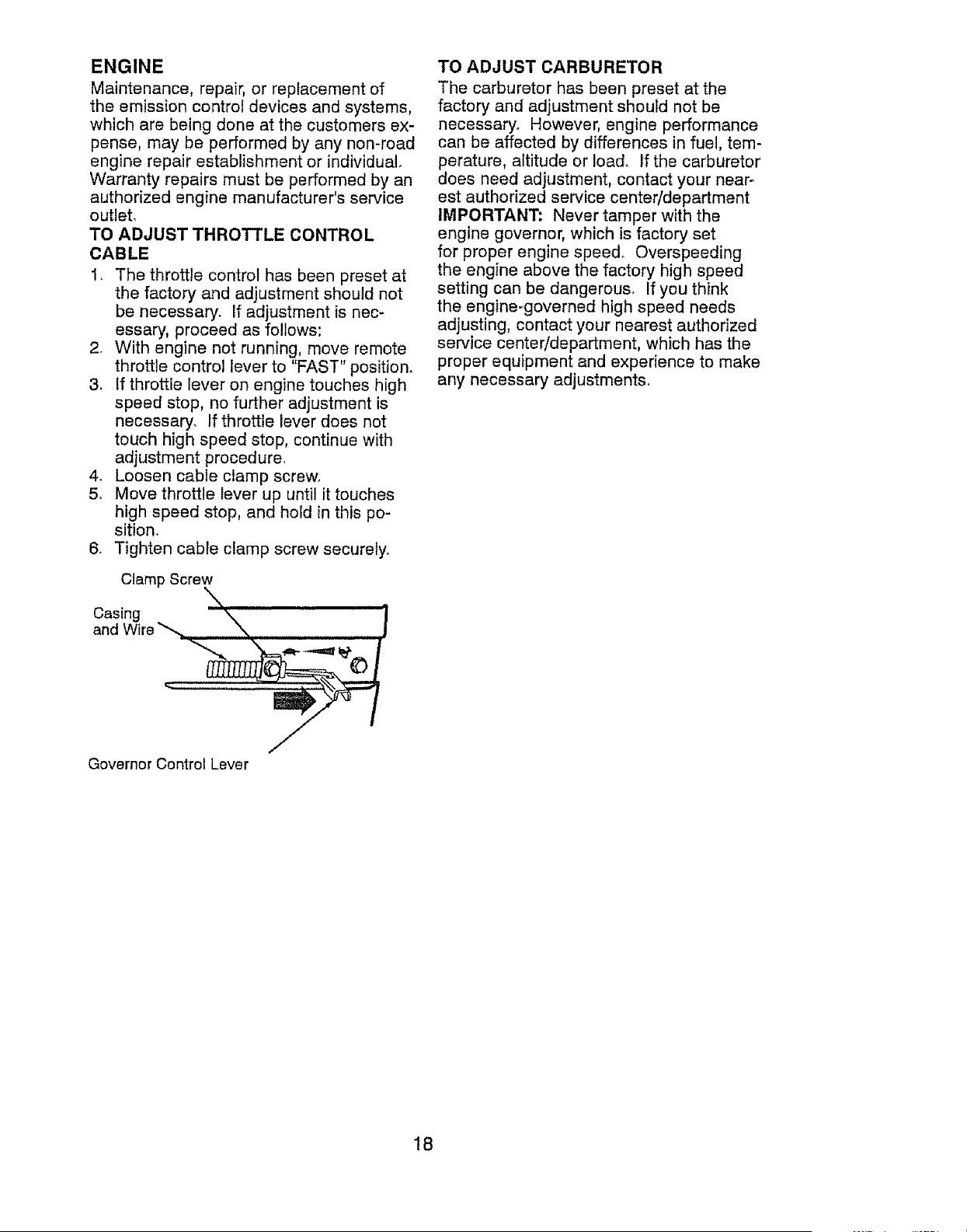
TO ADJUST THROTTLE CONTROL
CABLE
!_ The throttle control has been preset at
the factory and adjustment should not
be necessary. If adjustment is nec-
essary, proceed as follows:
2, With engine not running, move remote
throttle control lever to "FAST" position.
3. if throttle lever on engine touches high
speed stop, no further adjustment is
necessary. If throttle lever does not
touch high speed stop, continue with
adjustment procedure,
4_ Loosen cable clamp screw,
5, Move throttle lever up until it touches
high speed stop, and hold in this po-
sition,
6. Tighten cable clamp screw securely,.
Clamp Screw
aC_c_i_ire,_ X, ......................
Governor Control Lever
TO ADJUST CARBURETOR
The carburetor has been preset at the
factory and adjustment should not be
necessary° However, engine performance
can be affected by differences in fuel, tem-
perature, altitude or load. If the carburetor
does need adjustment, contact your near-
est authorized service center!department
IMPORTANT: Never tamper with the
engine governor, which is factory set
for proper engine spee& Overspeeding
the engine above the factory high speed
setting can be dangerous. If you think
the engine_governed high speed needs
adjusting, contact your nearest authorized
service center/department, which has the
proper equipment and experience to make
any necessary adjustments.
18
immediately prepare your tiller for storage
at the end of the season or ff the unit will
not be used for 30 days or more,
_CAUTION: Never store the tiller with
gasoline in the tank inside a building
where fumes may reach an open flame
or spark. Allow the engine to cool before
storing in any enclosure.
TILLER
1. Clean entire tiller (See "CLEANING" in
the Maintenance section of this man-
ual),
2, Inspect and replace belts, if necessary
(See belt replacement instructions in
the Service and Adjustments section of
this manual).
3. Lubricate as shown in the Maintenance
section of this manual.
4, Be sure that all nuts, bolts and screws
are securely fastened. Inspect moving
parts for damage, breakage and wear.
Replace if necessary,,
5. Touch up all rusted or chipped paint
surfaces; sand lightly before painting.
ENGINE
FUEL SYSTEM
IMPORTANT: it is important to prevent
gum deposits from forming in essential
fuel system parts such as the carburetor,
fuel filter, fuel hose, or tank during storage,
Also, alcohol blended fuels (called gasohol
or using ethanol or methanol) can attract
moisture which leads to separation and
formation of acids during storage, Acidic
gas can damage the fuel system of an
engine while in storage,
• Empty the fuel tank by starting the en-
gine and letting it run until the fuel lines
and carburetor are empty.
• Never use engine or carburetor cleaner
products in the fuel tank or permanent
damage may occur,
• Use fresh fuel next season,
NOTE: Fuel stabilizer is an acceptable
alternative in minimizing the formation of
fuel gum deposits during storage. Add
stabilizer to gasoline in fuel tank or stor-
age container. Always follow the mix ratio
found on stabilizer container. Run engine
at least 10 minutes after adding stabilizer
to allow the stabilizer to reach the carbu-
retor. Do not empty the gas tank and
carburetor if using fuel stabilizer.
ENGINE OIL
Drain oil (with engine warm) and replace
with clean oil, (See "ENGINE" in the Main-
tenance section of this manual),
CYLINDER
1. Remove spark plug,
2, Pour 1 ounce (29 ml) of oil through
spark plug hole into cyiinder_
3, Pull starter handle slowly several times
to distribute oil,
4, Replace with new spark plug,
OTHER
• Do not store gasoline from one season
to another,
• Replace your gasoline can if your can
starts to rust, Rust and/or dirt in your
gasoline will cause problems.
• tf possible, store your unit indoors and
cover it to give protection from dust and
dirt,
• Cover your unit with a suitable protective
cover that does not retain moisture. Do
not use plastic, Plastic cannot breathe
which allows condensation to form and
will cause your unit to rust.
IMPORTANT: Never cover tiller while en-
gine and exhaust areas are still warm_
19
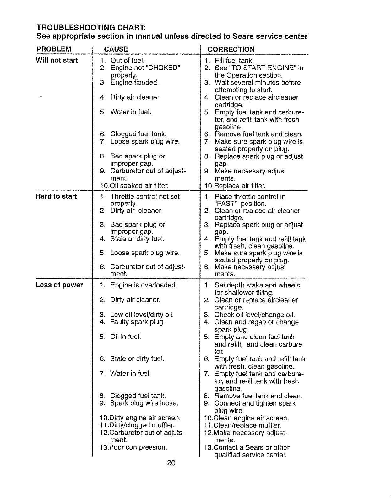
TROUBLESHOOTING CHART:
See appropriate section in manual unless directed to Sears service center
CAUSE
1. Out of fuel.
2. Engine not "CHOKED"
properly.
3. Engine flooded.
4. Dirty air cleaner.
5. Water in fuel.
PROBLEM
Will not start
& Clogged fuel tank.
7. Loose spark plug wire.
8. Bad spark plug or
improper gap.
9. Carburetor out of adjust-
ment.
10.Oil soaked air filter.
Hard to start 1. Throttle control not set
properly.
2. Dirty air cleaner.
3. Bad spark plug or
improper gap.
4. Stale or dirty fuel.
Loose spark plug wire.
Carburetor out of adjust-
ment.
5_
6.
Loss of power 1.
2.
3.
4.
8.
9.
Engine is overloaded°
Dirty air cleaner.
Low oil level/dirty oil.
Faulty spark plug.
5_ Oil in fuel.
6. Stale or dirty fuel.
7. Water in fuel.
Clogged fuel tank.
Spark plug wire loose.
lO.Dirty engine air screen.
11.Dirty/clogged muffler.
12.Carburetor out of adjuts-
ment.
1&Poor compression.
CORRECTION
1, Set depth stake and wheels
for shallower tilling,
2. Clean or replace aircleaner
cartridge.
3. Check oil level/change oil,
4, Clean and regap or change
spark plug,
5, Empty and clean fue! tank
and refilr, and clean carbure
tor.
6. Empty fuel tank and refill tank
with fresh, clean gasoline.
7o Empty fuel tank and carbure-
tor, and refill tank with fresh
gasoline.
& Remove fuel tank and clean.
9. Connect and tighten spark
plug wire.
10.Clean engine air screen.
11 .Clean/replace muffler.
12Make necessary adjust=
ments.
1&Contact a Sears or other
qualified service center.
2O
1. Fill fuel tank.
2_ See "TO START ENGINE" in
the Operation section.
3. Wait several minutes before
attempting to start.
4. Clean or replace aircleaner
cartridge.
5. Empty fuel tank and carbure-
tor. and refill tank with fresh
gasoline.
6o Remove fuel tank and clean.
7. Make sure spark plug wire is
seated properly on plug.
8. Replace spark plug or adjust
gap.
9. Make necessary adjust
ment&
lO.Replace air filter.
1. Place throttle control in
"FAST" position.
2. Clean or replace air cleaner
cartridge.
3. Replace spark plug or adjust
gap,
4o Empty fuel tank and refill tank
with fresh, clean gasoline,
5, Make sure spark plug wire is
seated properly on plug.
6, Make necessary adjust
ments,
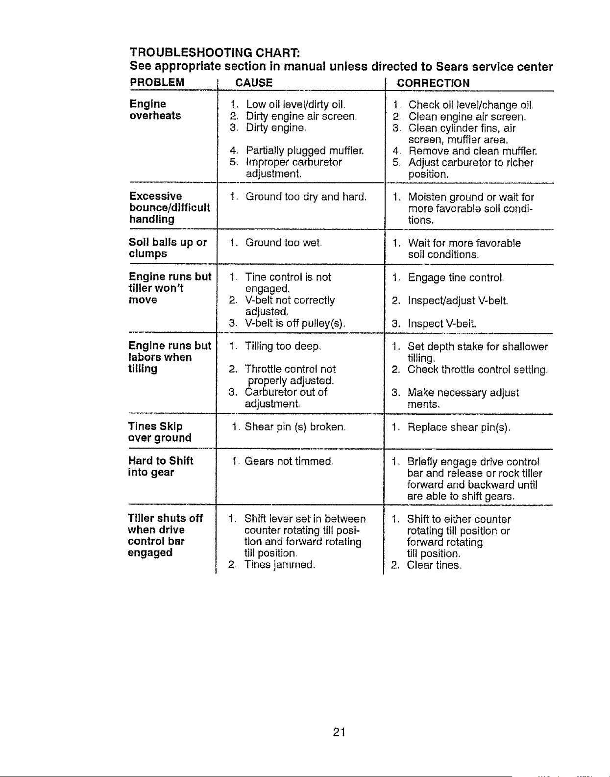
TROUBLESHOOTING CHART:
See appropriate section in manual unless directed to Sears service center
PROBLEM
Engine
overheats
CAUSE
Engine runs but
tiller won't
move
I, Low oil leve!/dirty oil,
2, Dirty engine air screen.
& Dirty engine,
4. Partially plugged muffler.
5. Improper carburetor
adjustment,
CORRECTION
1, Check oil level/change oil,
2, Clean engine air screen,
3, Clean cylinder fins, air
screen, muffler are&
4. Remove and clean muffler.
5, Adjust carburetor to richer
position.
Excessive 1, Ground too dry and hard. t, Moisten ground or wait for
bounce/difficult more favorable soil condF
handling tions,
Soil balls up or !, Ground too wet. t, Wait for more favorable
clumps soil conditions.
1_ Engage tine control,
Engine runs but
labors when
tilling
Tines Skip
over ground
1- Tine control is not
engaged,
2_ V-belt not correctly
adjusted.
3. V-belt is off pulley(s),
1, Tilling too deep,
2, Throttle control not
properly adjusted°
3, Carburetor out of
adjustment,
1. Shear pin (s) broken.
I, Gears not timmed
1_ Shift lever set in between
counter rotating till posi-
tion and forward rotating
till position.
2, Tines jammed,
Hard to Shift
into gear
Tiller shuts off
when drive
control bar
engaged
2, Inspect!adjust V-belL
3, Inspect V-belL
1. Set depth stake for shallower
tilling,
2o Check throttle control setting,
3. Make necessary adjust
ments,
1, Replace shear pin(s).
Briefly engage drive control
bar and release or rock tiller
forward and backward until
are able to shift gears,
I, Shift to either counter
rotating till position or
forward rotating
tiil position,
2, Clear tines,
21
Por dos (2) a5os, a partir de la fecha de compra, cuando esta Cultlvadora Craftsman se mantenga,
lubrique y afine seg_n las instrucciones para la operaci6n y el mantenimiento en el manual del
dueSo, Sears reparar&, gratis, todo defecto en el material y la mano de obra,
Esta Garantia no cubre:
• Articulos qua se desgastan durante el uso normal tales como los brazos, las bujias, los filtros de
aire y las correas,
• Reparaciones necesarias debido a! abuso o a la negligencia del operador, incluy#ndose a los
cig_le[3ales doblados y a la falta de mantenimiento del equipo seg_n las instrucciones que se
incluyen en el manual del duer_o.
• Si la Cultivadora Craftsman se usa para fines de arriendo, esta garantia se aplica solamente por
treinta (30) treintadias a parttr de la fecha de compra.
Et Servicio de Garantia esta disponlble al devolver la cuttivadora Craftsman al centro/departamento
de servicio Sears m&s cercano en los estados unidos.
Esta Garantia se aplica solamente mlentras el producto este en uso en los estados unidos. Esta
Garantia le otorga derechos legales especfficos, y puede que tambiSn tonga otros derechos qua
varian de estado a estado,
SEARS, ROEBUCK AND CO., D/817WA, HOFFMAN ESTATES_ IL 60179 U.S,A.
IMPORTANTE: Esta Maquina cortadora es capaz de amputar las manosy los pies y de lanzar
objetos, si no se observan las instrucciones de seguridad siguientes se pueden producir lesiones
graves o la muerte_
ENTRENAMIENTO
• Lea el Manual del Due6o cuidadosamente.
Familiaricese comptetamente con los
controles y con el uso adecuado del equipo.
Sepa c6mo parar la unidad y desenganchar
los controles r&pidamente,
• Nunca permita que los niSos operen el equi-
po, Nunca permtta que los adultos operen el
equipo sin los conocimientos adecuados.
, Mantenga et &rea de operaci6n despejada de
personas, especialmente ni5os pequeSos y
animales dom_sticos.
PREPARACION
• lnspeccione cuidadosamente el _rea en
donde se va usar el equipo y remueva los
objetos extraSos.
, Desenganche todos los embragues y cambie
a neutro antes de hacer arrancar et motor.
• No opera el equipo sin usar ropa exterior
adecuada. Use zapatos que mejoren el equi-
librio en superficies resbalosas.
, Maneje el combustible con cuidado pues es
muy inflamable.
• Use un envase de combustible aprobado.
, Nunca a5ada combustible a un motor en
funcionamiento o caliente.
• Llene el estanque de combustible afuera con
touche cuidado. Nunca llene el estanque de
combustible en un recinto cerrado.
• Vuelva a colocar la tapa del dep6sito de gas-
olina en forma segura y limpie el combustible
derramado antes de volver a arrancar,
• Use cordones de extensi6n y recept&culos,
segSn las especificaciones del fabricante,
para todas las unidades con motores de im-
pulsl6n o con motores de arranque el6ctrtco.
• Nunca trate de hacer ningSn ajuste mientras
que e! motor est# funclonando (excepto en
los casos especificamente recomendados
por el fabdcante).
OPERACION
• No ponga ni tas manos ni los pies cerca o
debajo de las piezas rotatortas.
•Tenga mucho cuidado cuando opere o cruce
entradas para autom6viles de ripio, senderos
o caminos, Est_ alerta en lo que se refiere a
los peligros escondidos o al tr&flco. No lleve
pasajeros.
22
• Despu6s de pegarle a un objeto extraSo,
pare el motor, remueva el atambre de la
bujia, inspeccione la cultivadora cuidadosa-
mente, para verificar si hay daSos, y repare
el daSo antes de volver a arrancar y operar la
cultivador&
, Tenga cuidado para evitar resbalarse o
caerse,
• Si la unJdad empieza a vibrar anormalmente,
pare el motor y rev{sela inmediatamente para
verificar la causa. La vibraci6n norma]mente
es un aviso de problemas,
, Pare el motor cuando abandone la posici6n
de operaci6n.
. Tome todas las precauciones posibles cu-
ando deje la m&quina desatendida, Desem
ganche los brazos, cambie a neutro y pare el
motor.
• Antes de limpiar, reparar e inspeccionar,
apague el motor y asegt)rese que todas
las partes en movimiento se han detenido.
Desconecte el alambre de la bujia, y mant_n-
galo alejado de _sta para evitar el arranque
por accidente, Deeconecte el cordon en los
motores el6ctricos,
• No haga funcionar el motor en recintos cer-
rados; los gases de escape son peligrosos,
• Nunca opere la cultivadora sin tas protec-
clones, y las planchas adecuadas y sin los
dem&s dispositivos de seguridad en su lugaro
• Mantenga a los niSos y a los animales do-
m6sticos alejados.
• No sobrecargue la capacidad de la m&quina,
tratando de cultivar a mucha profundidad,
muy r&pido.
• Nunca opere ta m&qulna a altas velocidades
en superficies resbalosas, Mire hacia atr&s y
tenga cuidado cuando retroceda.
• Nunca permita ta presencia de espectadores
cerca de la unidad.
• Use solamente accesorios y aditamentos
pare la cultivadora aprobados por el fabri-
cante.
• Nunca opere la cultivadora sin buena visibili-
dad o luz.
• Tenga cuidado el cultivar en terreno duro,
Los brazos pueden quedarse agarrados en
el suelo e impulsar a la cultivadora hacia
adelante. Si esto sucede, suelte los mangos
y no restrtnja la m&qutna.
MANTENIMIENTO Y ALMACENAMIEN-
TO
• Mantenga los accesorios y aditamentos de
la m&quina en buenas condiciones para el
funcionamlento.
• Revise las clavtjas de seguro, Eospernos
de montaje del motor y otros pernos, a
intervalos frecuentes, para vedficar si est&n
apretados en forma segura y asegurarse que
el equipo est_ en buenas condiciones de
funcionamiento
• Nunca guarde la mAquina con combustible
en el estanque de combustible dentro de un
edificio en donde hay fuentes de tgnici6n
presentes, tales como calentadores de agua
o det ambtente, secadoras de ropa u otros
artefactos parecidoso Permita que se enfr[e
el motor antes de guardarlo en algSn lugar
cerrado.
• Siempre refi6rase alas instrucciones en Ea
guia del operador para ver Eosdetalles de im-
portancia si la cuttivadora va a ser guardada
por un periodo de tiempo largo.
•OABusque este simbolo que sefiala las precau-
ciones de seguridad de importancia. Quiere
decir- I{IATENCIONllf ttiESTE ALERTOtfE SU
SEGURIDAD ESTA COMPROMETfDA.
_,PREOAUCI6N: Siempre desconecte el
alambre de la bujia y p6ngalo donde no pueda
entrar en contacto con la bujia, para evitar el
arranque por accidente, durante ta preparaci6n,
el transporte, el ajuste o cuando se hacen
reparaciones_
_ADVERTENClA: El tubo de escape de1
motor, algunos de sus constituyentes y algunos
componentes del vehiculo contienen o despren-
den productos qulmicos conocidos en el Estado
de California como causa de c&ncer y defectos
al nacimiento u otros daSos reproductivos
23
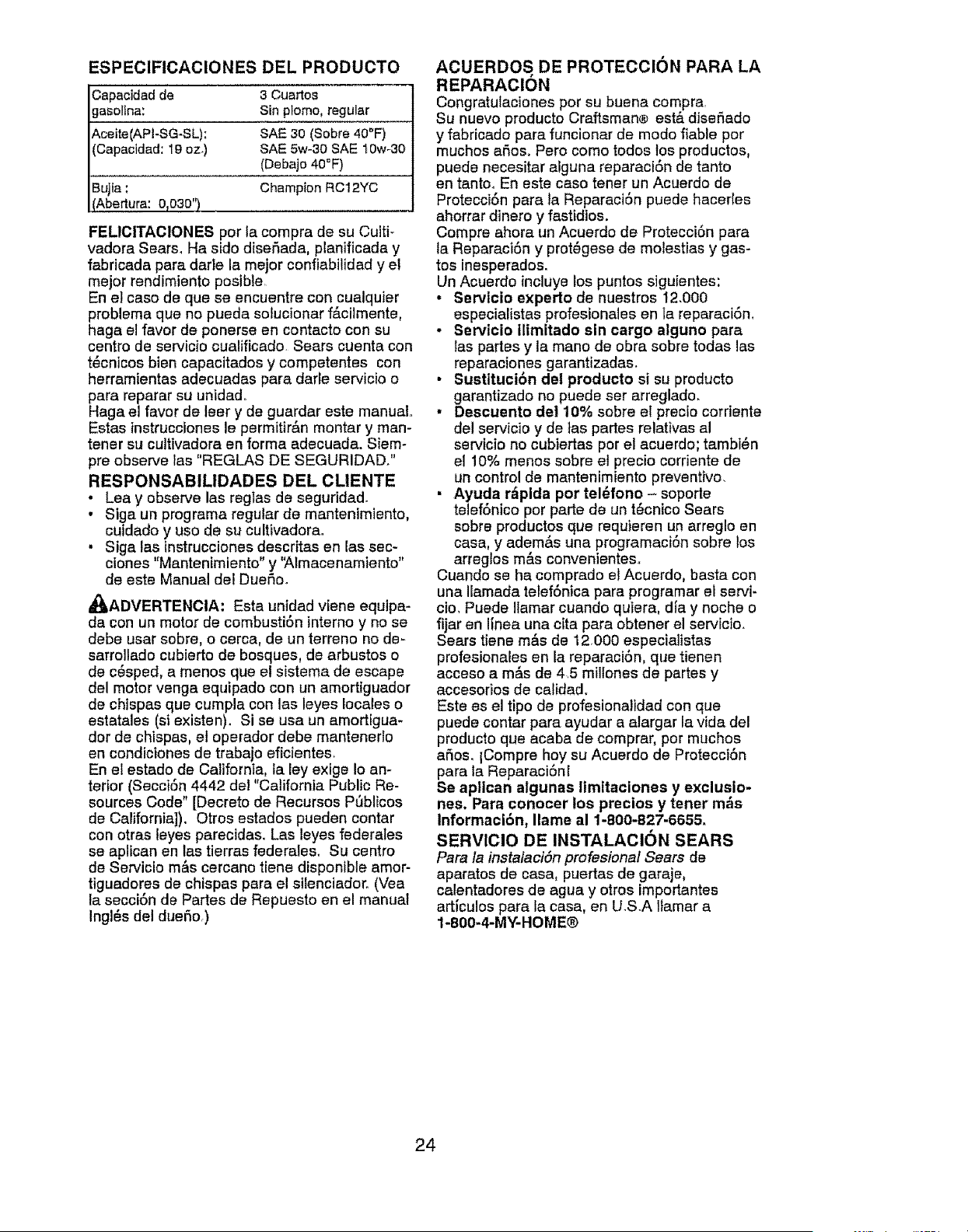
ESPECIFICACIONES DEL PRODUCTO
Capacidadde 3 Cuartos
gasoline: Sin plomo, regular
Aceite(APFSG-SL): SAE30 (Sobre 40°F)
(Capacldad:19 oz.) SAE5w-30 SAE 10w-30
(Debajo40_F)
ChampionRC12YC
Bujta:
(Abertura: 0T030")._
FEL1CITACIONES per la compra de su Cuiti-
vadora Sears, Ha sido diser'_ada, planificada y
fabricada pare darle la meier confiabilidad y el
mejor rendimiento posible
En e! caso de que se encuentre con cualquier
problema que no pueda solucionar f&cilmente,
haga el favor de ponerse en contacto con su
centre de servicio cualificado. Sears cuenta con
t6cnicos bien capacitados y competentes con
herramientas adecuadas pare darle servicio 0
pare reparar su unidad.
Haga el favor de leer y de guarder este manual.
Estas instrucciones le permitir&n montar y man-
tener su cultivadora en forma adecuada. Siem-
pre observe las "REGLAS DE SEGURIDAD/'
RESPONSABILIDADES DEL CLIENTE
• Lea y observe las reglas de seguridad
• Siga un programa regular de mantenimiento,
cuidado y uso de su cultivadora.
• Siga las instrucciones descritas en las sec-
ciones "Mantentmiento" y 'Atmacenamiento"
de este Manual del Due6o.
,_ADVERTENCiA: Esta unidad viene equlpa-
da con un motor de combusti6n interne y no se
debe user sobre, o cerca, de un terreno no de-
sarrollado cubierto de bosques, de arbustos o
de c6sped, a menos que el sistema de escape
del motor venga equipado con un amortiguador
de chlspas que cumpla con las leyes locales o
estatales (si existen). Si se usa un amortigua-
tier de chispas, el operador debe mantenerlo
en condiciones de trabajo eficientes_
En el estado de California, ta ley exige Io an-
terior (Secci6n 4442 de] "California Public Re-
sources Code" [Decreto de Recursos PSblicos
de California]), Otros estados pueden center
con otras teyes parecidas. Las leyes federates
se aplican en las tierras federales. Su centre
de Servicio m&s cercano tiene dispontble amor-
tiguadores de chispas pare el silenciador. (Vea
la secci6n de Partes de Repuesto en el manual
Ingl6s del due6o,)
ACUERDOS, DE PROTECClON PARA LA
REPARACION
Congratulaciones per su buena compra
Su nuevo producto Craftsman® estA dise6ado
y fabricado pare funcionar de mode liable per
touches a6os. Pero come redes los productos,
puede necesitar alguna reparaci6n de tanto
en tanto. En este case tener un Acuerdo de
Protecci6n pare la Reparaci6n puede hacerles
ahorrar dinero y fastidios.
Compre ahora un Acuerdo de Protecci6n pare
la Reparaci6n y prot6gese de molestias y gas-
tos inesperades.
Un Acuerdo incluye los puntos siguientes:
• Servlcio experto de nuestros 12.000
especialistas profesionales en ta reparaci6n_
, Servicio ilimitado sin cargo alguno pare
tas partes y la mane de obra sobre todas las
reparaciones garantizadas.
• Sustttucibn del producto si su producto
garantizado no puede set arreglado.
• Descuento del 10% sobre el precio corriente
de! servicio y de las partes relatives al
servicio no cubiertas per el acuerdo; tambi6n
el 10% menos sobre el precio corriente de
un control de mantenimiento preventive.
• Ayuda r,_pida per tel6fono - soporte
telef6nico per parte de un t6cnico Sears
sobre productos que requieren un arreglo en
case, y adem&s una programaci6n sobre los
arreglos m&s convenientes.
Cuando se ha comprado el Acuerdo, baste con
una Ilamada telef6nica pare programar el servi-
cto, Puede Ilamar cuando quiera, die y noche o
fijar en linea una cita pare obtener el servicio.
Sears tiene m&s de 12.000 especialistas
profesionales en la reparaci6n, que tienen
acceso a m&s de 4 5 miltones de partes y
accesorios de calidad.
Este es el tipo de profesionalidad con que
puede center pare ayudar a alargar la vide del
producto que acaba de comprar, per muchos
aSos. ICompre hey su Acuerdo de Protecci6n
pare la Reparacionl
Se apllcan algunas ltmitaciones y exclusio-
nes. Para conocer los precios y tener m_,s
Informacl6n, Ilame al 1-800-B27-665&
SERViClO DE INSTALACION SEARS
Pare la instalaci6n profesional Sears de
aparatos de case, puertas de garaje,
calentadores de agua y otros importantes
articulos pare la case, en U.S.A ltamar a
1-800-4-MY-HOME®
24
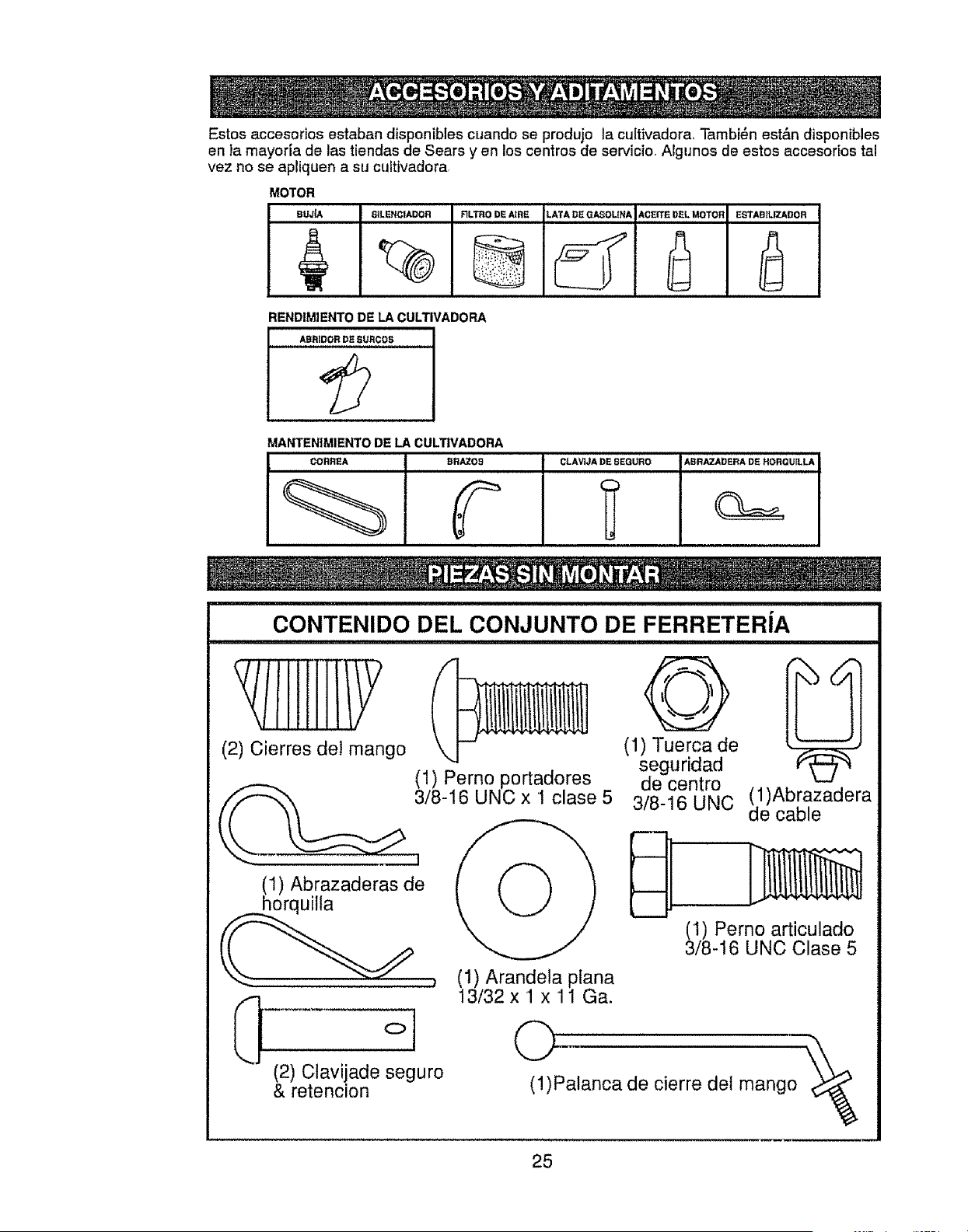
Estos accesodos estaban disponibles cuando se produjo ta cultivadora, Tambi_n est&n disponibles
en la mayoria de las tiendas de Sears yen los centros de servicio_ Afgunos de estos accesor[os tal
vez no se apriquen a su cultivadora,
MOTOR
BUJ{A 8;LENCIADOR RLTRODEA_RE LATADEQ/_OLINA ACEITEDELMOTOR ESTAB_LIZADOR
RENDIMIENTO DE LA CULTIVADORA
AHRIDOR DE -_URCOS
¢
MANTEN]MIENTO DE LA CULTWADORA
CORREA BRAZo_
CLAViJA:DE8EGuRo ABRAzADERADS HORQuiLLA
_P
CONTENIDO DEL CONJUNTO DE FERRETERfA
(2) Cierres del mango
(1) Abrazaderas de
__horquitla
(2) Clavijade seguro
& retencion
(1) Perno portadores
3/8-16 UNC x 1 clase 5
@
(1) Arandela plana
13/32 x 1 x 11 Ga.
©
0
(1) Tuerca de
seguridad
de centro
3/8-16 UNC
(1)Abrazadera
de cable
(1) Perno articulado
3/8-16 UNC Clase 5
(!)Palanca de cierre def mango
25
Su cultivadora nueva ha side montada en la fAbrica, con la excepci6n de aquelias partes que se
dejaron sin montar per razones de envio. Para asegurarse que la cultivadora operara en forma
segura y adecuada, todas tas partes y los articulos de ferreteria que monte tienen qua estar apre-
tados en forma segura° Use las herramientas correctas, segt_n sea necesario, para asegurarse de
que queden apretadas en forma segura.
HERRAMIENTAS NECESARIAS PARA
EL MONTAJE
Se le facilitar& el mentaje si cuenta con un
juego de Ilaves de tube. Se han enumerado los
tamar_os est&ndar de las llaves_
(1) Cuchillo para rode use
(1) Cortador de alambres
(!) Destornillador
(!) Mediclor de presi6n de las tlantas
(1) Par de alicates
(1) Llave de 9/16"
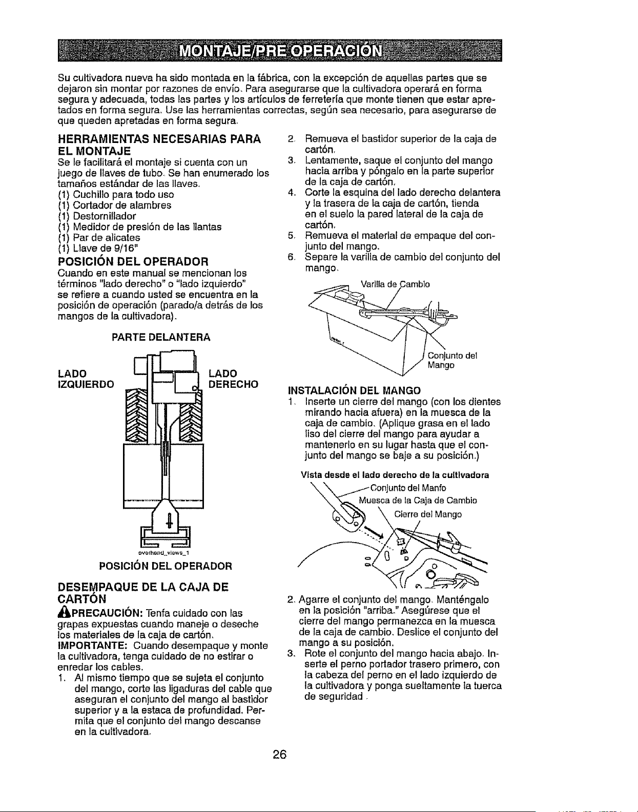
POSIOI6N DEL OPERADOR
Cuando en este manual se mencionan los
t6rminos "lade derecho" o "lade izquierdo"
se refiere a cuando usted se encuentra en la
posici6n de operacl6n (parado/a detrAs de los
mangos de la cultivadora).
2. Remueva et bastidor superior de la caja de
cart6nr
3. Lentamente, sa.que el conjunto del mango
hacia arriba y pongalo en ia parte superior
de la caja de cart6n,
4. Corte la esquina del lade derecho delantera
y la trasera de la caja de cart6n, tienda
en el suelo la pared lateral de la caja de
cart6n,
5, Remueva el material de empaque del con-
junto del mango.
6. Separe la varilia de cambio del conjunto del
mango,
Var]Ha de
PARTE DELANTERA
LADe
IZQUIERDO
LADe
DERECHO
overhead view8 1
POSICION DEL OPERADOR
DESEMPAQUE DE LA CAJA DE
CARTON
_PRECAUCI6N: Tenfa cuidedo con las
grapas expuestas cuando maneje o deseche
los materiales de la caja de cart6n,
1MPORTANTE: Cuando desempaque y monte
la cuttivadora, tenga cuidado de no estirar o
enredar los cables.
1. AI mismo tiempo que se sujeta et conjunto
del mango, corte las tigaduras del cable que
aseguran el conjunto del mango al bastidor
superior y a la estaca de profundidad, Per-
mita qua el conjunto del mango descanse
en la cultivadora.
Oonjunto del
Mango
INSTALAClON DEL MANGO
1, Inserte un cierre det mango (con los dientes
mirando hacia afuera) en la muesca de la
caja de cambio, (Apltque grasa en ei lade
fiso det cierre del mango para ayudar a
mantenerlo en su lugar hasta qua el con-
junto del mango se baje a su posici6n_)
Vista dasdeel lade derechode la cultlvadora
COnJuntodelManfo
escade la Caja de Cambio
Cierredel Mango
2. Agarre el conjunto del mango. Mant_ngalo
en la posici6n "arribao" Aseg_rese que el
cierre del mango permanezca en la muesca
de la caja de cambio_ Deslice el conjunto del
mango a su posici6n,
3. Rote el conjunto del mango hacia abajo_ Im
serte el pemo portador trasero pdmero, con
ia cabeza del perno en el tado izquierdo de
la cultivadora y ponga sueltamente la tuerca
de seguridad.
26
Conluntodel mango
posoct6n'Ardba"
%,, de clerre del mango
"_.-%para su_etarla
clerre d_ mango para _N_)_. _-"_
moverla _ *,_
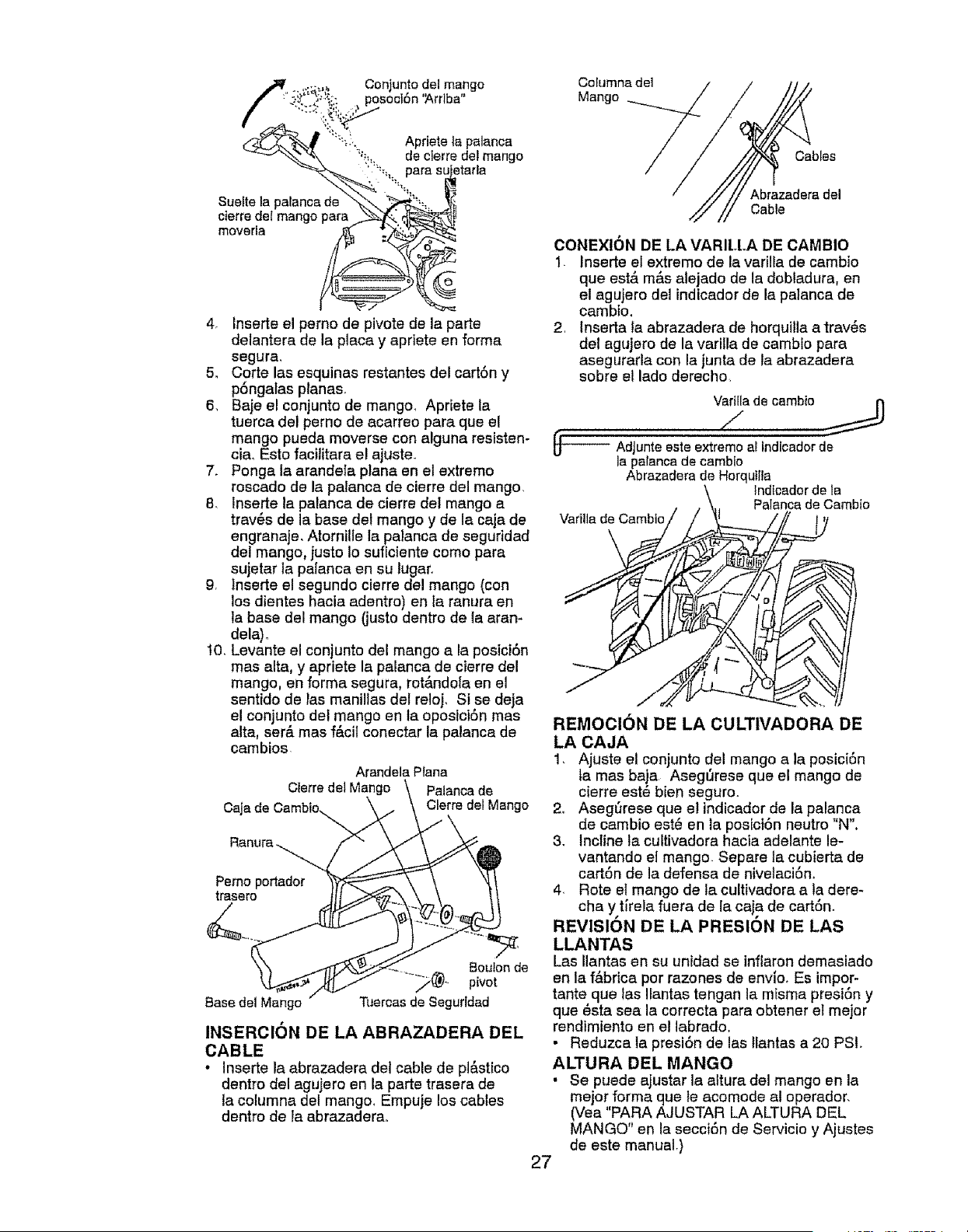
4, Inserte el perno de pivote de la parte
delantera de la placa y apriete en forma
segura,
5. Corte las esquinas restantes del cart6n y
pSngalas ptanas.
6, Baje el conjunto de mango_ Apriete la
tuerca del perno de acarreo para qua e!
mango pueda moverse con alguna resisten-
cia_ Esto facllitara e! ajuste.
7, Ponga la arandela plana en el extremo
roscado de la palanca de cierre del mango,
8, lnserte la patanca de cierre del mango a
trav6s de la base del mango y de la caja de
engranaje, Atornille la palanca de seguridad
del mango, justo Io suficiente como para
sujetar la palanca en su lugar,
9r lnserte el segundo cierre del mango (con
los dientes hacia adentro) en la ranura en
la base del mango (justo dentro de 1aaran-
dela),
10_Levante e! conjunto del mango a la posici6n
mas alta, y apriete la palanca de cierre del
mango, en forma segura, rot&ndola en el
sentido de las manillas del reloj, Si se deja
e! conjunto del mango en la oposici6n mas
alta, ser_. mas f&cil conectar la palanca de
cambios
Arandela Plana
Cterre del Mango Palanca de
Caja de Cambto Cterre del Mango
Pemo portador
trasel'o
Base de1 Mango
Boulon de
pivot
Tuercasde Seguddad
INSERCION DE LA ABRAZADERA DEL
CABLE
• Inserte la abrazadera del cable de pl&stico
dentro del agujero en la parte trasera de
la columna del mango_ Empuje loscables
dentro de la abrazaderao
Co_umna de1
Mango
Cables
Abrazadera del
Cable
OONEXION DE LA VARILLA DE CAMBIO
1. Inserte el extremo de la vadlFade cambio
que est& m&s alejado de la dobladura, en
el agujero del indicador de la palanca de
camblo.
2 lnserta la abrazadera de horquilla a trav6s
del agujero de la varilla de cambio para
asegurarla con la junta de la abrazadera
sobre el lado derecho
Vadlladecambio 13
Z
_-'_ AdJunteeste extremo al fndlcadorde
la palancade cambio
Abrazaderade Horquilla
IndIcadorde la
Palancade Cambio
Varillade Cambto
REMOClON DE LA CULTIVADOFIA DE
LA CAJA
1, Ajuste el conjunto del mango a la posici6n
la mas baja Aseg6rese que el mango de
cierre est6 bien seguro.
2_ Asegt_rese qua e! indicador de la palanca
de cambio est_ en la posici6n neutro "N".
3, Incline la cultivadora hacia adelante le-
vantando el mango Separe ta cubierta de
cart6n de la defensa de nivetaci6n.
4, Rote et mango de la cultivadora a la dere-
cha y tirela fuera de la caja de cart6n.
REVISION DE LA PRESION DE LAS
LLANTAS
Las Ilantas en su unidad se inflaron demasiado
en la f&brica por razones de envioo Es impor-
tante que 1as Ilantas tengan la misma presi6n y
qua _sta sea la correcta para obtener el mejor
rendimiento en el labrado.
• Reduzca la presi6n de las flantas a 20 PSI.
ALTURA DEL MANGO
• Se puede ajustar la altura del mango en la
mejor forma que te acomode al operador,
(Vea "PARA AJUSTAR LA ALTURA DEL
MANGO" en la secci6n de Servicio y Ajustes
de este manual.)
27
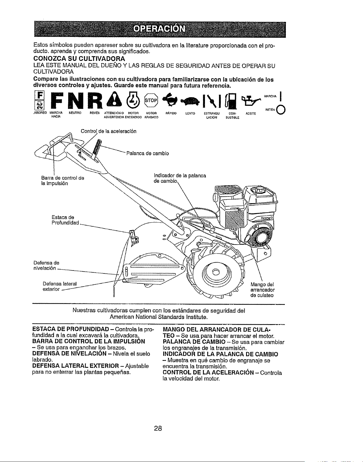
Estos slmbolos pueden apareser sobre su cultivadora en la literature proporcionada con el pro-
ducto_ aprenda y comprenda sus significadoso
CONOZCA SU CULTIVADORA
LEA ESTE MANUAL DEL DUEt_O Y LAS REGLAS DE SEGURIDAD ANTES DE OPERAR SU
CULTIVADORA
Compare las ilustraciones con su cultivadora pare familiarizarse con la ubicacibn de los
diversos controles y ajustes, Guarde este manual pare futura referencia.
F N R & ® .= I\l
.ABOR_O MARCHA NEUTRO R_V_S ATI'ENCK_N O thSt TO R MO=[OR RAPID{) LENTO ESTRANGU COM= AcEFrE
HAC_ ADVERTE_CIA ENCENOIDO APAGADO LACI_N _UST_]LE
Control de Ia aceleracf6n
Palanca de cambto
Barra de control de
la lmpuisi6n
lndtcadorde la palanca
de oambto
Estaca de
Defense de
nivelacf6n_ * '
{
Defensa lateral Mangodet
exterior arrancador
de cufateo
Nuestras cultivadoras cumplen con los est&ndares de seguridad de!
American National Standards Institute.
ESTACA DE PROFUNDtDAD - Controta la pro-
fundidad ala cual excavar& la cultlvadora.
BARRA DE CONTROL DE LA IMPULSION
- Se usa para enganchar los brazos.
DEFENSA DE NIVELACION - Nivela el suelo
labrado.
DEFENSA LATERAL EXTERIOR - Ajustable
pare no enterrar las plantas pequefias.
MANGO DEL ARRANCADOR DE CULA-
TEO - Se usa pare hacer arrancar el motor.
PALANCA DE CAMBtO -- Se usa pare cambiar
los engranajes de la transmisi6n.
INDICADOR DE LA PALANOA DE CAMBIO
- Muestra en qu_ cambio de engranaje se
encuentra la transmisi6n,
CONTROL DE LA ACELERAOI6N - Controla
ta velocidad de! motor,
28
La operaci6n de cualquier cultivadora puede hacer que saiten objetos extraSos
dentro de sus ojos, 1oque puede producir dafios graves en _stos. Siempre use
anteojos de seguridad, o protecciones para los ojos antes de hacer arrancar su culti-
vadora o mientras este labrando con ella. Recomendamos el uso de la mascara de
seguridad de visi6n amplia, para uso sobre los espejuelos o anteojos de seguridad
est&ndar.
COMO USAR SU CULTIVADORA
Sepa c6mo operar todos los controies antes de
agregar combustible y aceite o antes de tratar
de hacer arrancar el motor.
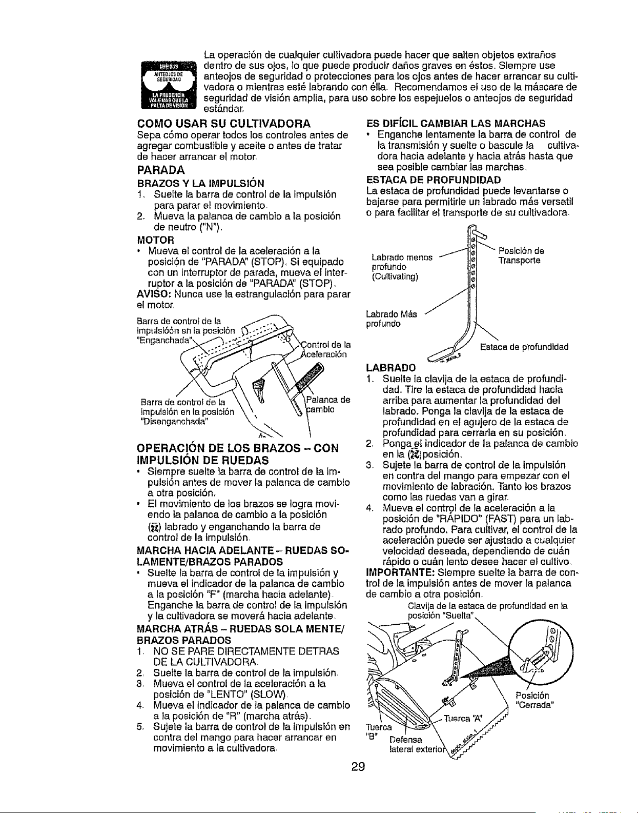
PARADA
BRAZOS Y LA IMPULSION
1, Suelte la barra de control de la impulsi6n
para parar el movtmiento.
2. Mueva la palanca de cambio a la posici6n
de neutro ("N").
MOTOR
• Mueva et control de la aceleraci6n a la
posici6n de "PARADA" (STOP), Si equipado
con un interruptor de parada, mueva el inter-
ruptor a la posicion de "PARADA_' (STOP).
AVISO: Nunca use la estranguiaci6n para parar
el motor.
Barra de controf de la
tmpuls166nen ia posict6n
"Enganchada"x
ES DIFIClL CAMBIAR LAS MARCHAS
• Enganche lentamente la barra de control de
la transmisi6n y suelte o bascule la cultiva-
dora hacia adelante y hacia atr&s hasta que
sea posible cambiar las marchas,
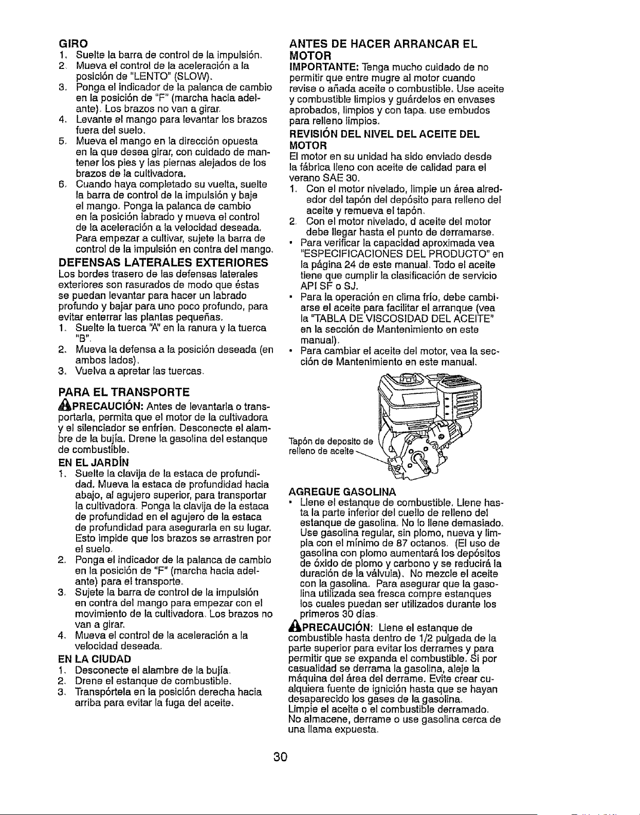
ESTACA DE PROFUNDIDAD
La estaca de profundidad puede levantarse o
bajarse para permitirle un labrado m&s versatil
o para facilitar el transporte de su cultivadora.
Labrado menos
profundo
(Cultivating)
Posici6n de
Transporte
LabradoM&s
profundo
Estaca de profundidad
Barrade controlde la F%lancade
tmpulst6nen la posbi6n
"Dfsenganchada" \
OPERAOION DE LOS BRAZOS- CON
IMPULSION DE RUEDAS
, Siempre suelte Ia barra de control de la im-
pulsi6n antes de mover la palanca de cambio
a otra posici6n.
• El movimiento de los brazos se Iogra movi-
endo la palanca de cambio a la posici6n
(_;) tabrado y enganchando la barra de
control de la impulsi6n.
MARCHA HAOIA ADELANTE - RUEDAS SO-
LAMENTE!BRAZOS PARADOS
, Suelte ta barra de control de la impulsi6n y
mueva el indicador de la palanca de cambio
a la posici6n "F" (marcha hacia adeiante)-
Enganche la barra de control de la impulst6n
y la cultivadora se mover#, hacia adelante.
MARCHA ATRAS - RUEDAS SOLA MENTE/
BRAZOS PARADOS
! NO SE PARE D]RECTAMENTE DETRAS
DE LA CULTIVADORA
2. Suelte la barra de controi de ta impulsi6n.
3. Mueva el control de la aceleraci6n a la
posici6n de "LENTO" (SLOW)_
4. Mueva el tndicador de la palanca de cambio
a la posici6n de "R" (marcha atr&s).
5. Sujete la barra de control de la fmpulsi6n en
contra del mango para hacer arrancar en
movimiento a la cultivadora_
LABRADO
1. Suelte la clavija de la estaca de profundi-
dad. Tire la estaca de profundidad hacia
arriba para aumentar la profundidad del
labrado. Ponga la clavija de la estaca de
profundidad en el agujero de la estaca de
profundidad para cerrada en su posici6n.
2, Ponga el indicador de la palanca de cambio
en la (_)posici6n,
3. Sujete la barra de control de la impulsi6n
en contra del mango para empezar con el
movimiento de labraci6n. Tanto los brazos
como tas ruedas van a girar.
4. Mueva el control de la aceleraci6n a la
posici6n de "R,_,PIDO" (FAST) para un lab-
rado profundo. Para cuttivar, et control de la
aceleraci6n puede ser ajustado a cualquier
vetocidad deseada, dependiendo de cu&n
r#`pido o cu&n }ento desee hacer el cultivo
IMPORTANTE: Siempre suelte la barra de con-
trol de ta impulsi6n antes de mover la patanca
de cambio a otra posici6n,
Clavijade laestaca de profundidaden la
posict6n"SueRa"
Tuerca
"B" Defensa
lateral
Postot6n
"Cerrada"
29
GIRO
1, Suelte la barra de control de la impulsi6n,
2 Mueva el control de la aceleraci6n ala
posici6n de "LENTO" (SLOW).
3. Ponga el indicador de la patanca de cambio
en la posici6n de "F" (marcha hacla adel-
ante)_ Los brezos no van a girar.
4, Levante el mango pare levantar los brazos
fuera del suelm
5r Mueva el mango en la direcci6n opuesta
en la que desea girar, con cuidado de man-
tener los pies y tas piernas ale]ados de los
brazos de _acultivadora,
5, Cuando haya completado su vuelta, suelte
la barra de control de la impulsi6n y baje
el mango° Ponga la palanca de cambio
en la posici6n labrado y mueva el control
de la aceleraci6n ala velocidad deseada°
Para empezar a cultivar, sujete la barra de
control de la impulsi6n en contra del mango°
DEFENSAS LATERALES EXTERIORES
Los bordes trasero de tas defenses laterales
exteriores son rasurados de modo que 6stas
se puedan levantar para hacer un labrado
profundo y bajar pare uno poco profundo, para
evitar enterrar las plantas pequeSas_
1o Suelte la tuerca '_' en la ranura y la tuerca
2. Mueva la defense ala posici6n deseada (en
ambos lados),
3, Vuelva a apretar las tuercas.
PARA EL TRANSPORTE
_,PRECAUCI6N: Antes de levantada o trans-
portarla, permita que el motor de la cultivadora
y el sttenciador se enfrien. Desconecte el alam-
bre de la bujia. Drene la gasoline del estanque
de combustible,
EN EL JARDIN
I. Suelte la clavija de la estaca de profundi-
dad, Mueva la estaca de profundidad hacia
abajo, ai agujero superior, para transportar
la cultivadora. Ponga la clavija de la estaca
de profundidad en el agujero de la estaca
de profundidad para asegurarla en su lugar,
Esto impide que los brazes se arrastren por
elsue]o.
2. Ponga elindicadorde lapalancade cambio
en laposici6nde "F"(marchahaciaadel-
ante) para el transporte_
3, Sujete la barra de control de la impulsi6n
en contra del mango para empezar con el
movimiento de ta cultivadora, Los brazos no
van a girar,
4. Mueva el control de la aceleraci6n ala
velocidad deseada,
EN LA ClUDAD
1. Desconecte el alambre de la bujia.
2. Drene el estanque de combustible.
3, Transp6rtela en la posici6n derecha hacia
arriba para evitar la fuga del aceite.
ANTES DE HACER ARRANCAR EL
MOTOR
IMPORTANTE; Tenga mucho cuidado de no
permitir que entre mugre al motor cuando
revise o armadaaceite o combustible° Use aceite
y combustible limpios y gu&rdelos en envases
aprobados, limpios y con tapa. use embudos
pare relleno limpioso
REVISION DEL NIVEL DEL ACEITE DEL
MOTOR
El motor en su unidad ha sido enviado desde
la f&brica Ileno con aceite de calidad para el
verano SAE 30.
1_ Con el motor nivelado, limpie un &rea alred-
edor del tap6n del dep6sito para relleno del
aceite y remueva el tap6n_
2 Con el motor nivelado, d aceite del motor
debe liegar haste el punto de derramarse.
• Pare verificar la capacidad aproximada yea
"ESPECIFICAC!ONES DEL PRODUCTO" en
la p_.gina 24 de este manual, Todo el aceite
tiene que cumplir la ctasfficaci6n de servicio
APt SF o SJ.
• Para la operaci6n en clima frio, debe cambi-
arse el aceite pare facilitar el arranque (yea
la "TABLA DE VISCOStDAD DEL ACEITE"
en la secci6n de Mantenimiento en este
manual).
• Para cambiar el aceite del motor, vea la sec-
ci6n de Mantenimiento en este manual,
Tap6n de deposlto de
relleno de aceffe
AGREGUE GASOLINA
• Uene el estanque de combustible, Llene has-
tala parte inferior del cuello de relleno del
estanque de gasoline. No Io Ilene demasiado.
Use gasolina regular, sin plomo, nueva y lim-
pla con el mfnimo de 87 octanos, (El uso de
gasolina con plomo aumentar& los dep6sitos
de 6xido de plomo y carbono y se reducir& la
duraci6n de la v&lvuta), No mezcle el aceite
con la gasolina. Pare asegurar que la gaso-
line utilizada sea fresca compre estanques
los cuales puedan ser utUizados durante los
primeros 30 dies,
_PRECAUCION: Lleneel estanque de
combustible hasta dentro de 1/2 pulgada de la
parte superior para evitar los derrames y para
permitir que se expanda el combustible° Si por
casualidad se derrama la gasolina, aleje la
maquina del &rea del derrame. Evite crear cu-
alquiera fuente de tgnicionhasta que se hayan
desaparecido los gases de la gasoltna_
Limpie el aceite o el combustible derramado.
No almacene, derrame o use gasoline cerca de
una llama expuesta.
3O
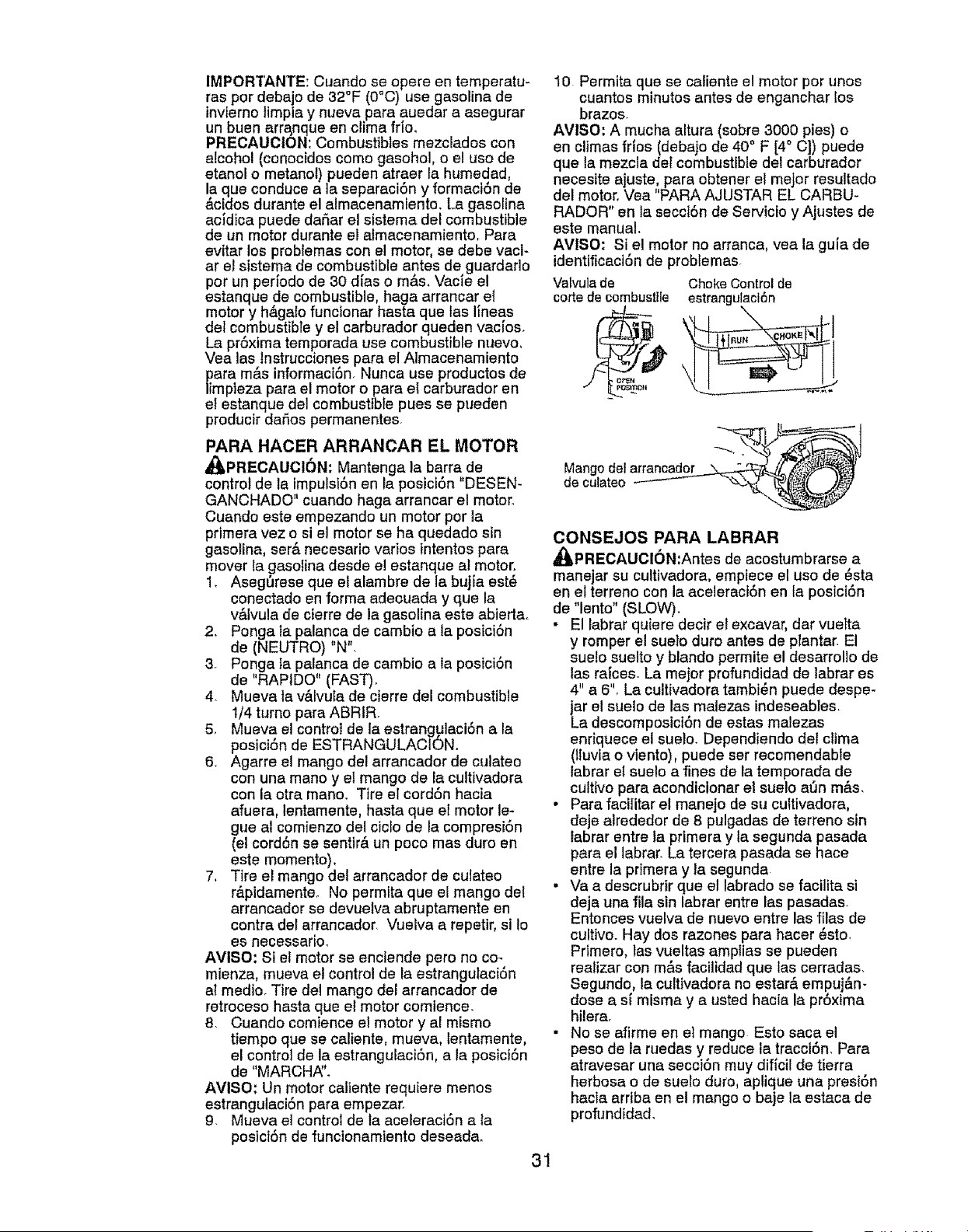
IMPORTANTE: Cuando se opere en temperatu-
res por debajo de 32°F (0°C) use gasoline de
invierno limpla y nueva pare auedar a asegurar
un buen arra,nque en clime fno.
PRECAUCION: Combustibles mezclados con
alcohol (conocidos como gasohol, o el uso de
eteno! o metanot) pueden atraer la humedad,
la que conduce a la separaci6n y formaciSn de
ac[dos durante el almecenamiento. La gasoline
acJdica puede daSar el sistema del combustible
de un motor durante el afmacenamiento+ Para
evitar los problemas con el motor, se debe vacl-
ar et sistema de combustible antes de guardado
pot un periodo de 30 dies o m&s. Vacie el
estanque de combustible, haga arrancar el
motor y h&galo funcionar haste que las Ifneas
del combustible y el carburador queden vacios.
La proxime temporada use combustible nuevo,
Vea las tnstrucciones pare el Almacenamiento
pare mas informacion. Nunca use productos de
limpieza pare el motor opara el carburador en
el estanque del combustible pues se pueden
producir daSos permanentes.
PARA HACER ARRANCAR EL MOTOR
_,PRECAUCI6N: Mantenga la barra de
control de la impulsl6n en la posici6n "DESEN-
GANCHADO" cuando haga arrancar el motor.
Cuando este empezando un motor por la
primera vez o si el motor se he quedado sin
gasolina, ser& necesario varios intentos pare
mover la gasolina desde el estanque el motor.
1. Aseg_rese que el alambre de la bujia est_
conectado en forma adecuade y que la
v#,lvula de cierre de la gasolina este abiertao
2, Ponga la palanca de cambio ala posici6n
de (NEUTRO) "N".
3. Ponga la palanca de cambio ata posici6n
de "RAPIDO" (FAST).
4. Mueve la v_.lvule de cierre del combustible
1/4 turno pare ABRIR.
5. Mueva el control de Ia estrangulaci6n ala
posiciSn de ESTRANGULACION,
6. Agarre el mango del arrancador de culeteo
con una mano y el mango de la cultivadora
con la otra mano. Tire el cordSn hacia
efuera, lentamente, haste que el motor le-
gue al comienzo del ciclo de le compresi6n
(el cord6n se senttr& un poco mas duro en
este momento),
7, Tire el mango del arrancador de culateo
r&pidamente° No permita que el mango del
arrancador se devuetva abruptamente en
contre del arrancador. Vuelva a repetir, si Io
es neoessario,
AVlSO: Si et motor se enciende pero no co-
mienza, mueva et control de le estrangulaci6n
al medic. Tire del mango del arrancador de
retroceso hasta queet motor comience.
8. Cuando comience el motor y al mismo
tiempo que se caliente, mueva, lentamente,
el control de le estrangulaciSn, ala posiciSn
de "MARCH,_L
AVlSO: Un motor caliente requiere menos
estrangulaci6n pera empezar.
9. Mueva el control de la aceleraci6n ala
posici6n de funcionemiento desead&
10 Permita que se caliente el motor por unos
cuantos minutos antes de enganchar los
brazos.
AMISO; A mucha altura (sobre 3000 pies) o
en climes frios (debajo de 40° F [4° C]) puede
que ta mezcla deI combustible del carburador
necesite ajuste, pare obtener el mejor resultado
del motor. Vea "PARA AJUSTAR EL CARBU-
RADOR" en ta secci6n de Servicio y Ajustes de
este manual.
AMISO: Si e! motor no arrance, vea le gula de
identificaciSn de problemas.
31
Valvulade
torte de combusttle
o
ChokeControlde
estrangulaci6n
Mango del arrancad___"_
,oo°,o,eot--
CONSEJOS PARA LABRAR
_PRECAUCI6N:Antes de acostumbrarse a
manejer su cultivadora, empiece el uso de 6sta
en el terreno con le aceleraci6n en la posici6n
de "lento" (SLOW).
• El labrar quiere decir el excavar, dar vuelta
y romper el suelo duro antes de plantar. El
sueto suelto y blando permite el desarrollo de
tas raices. La mejor profundidad de labrar es
4" a 6", La cultivadora tambi6n puede despe-
jar el suelo de las malezas indeseables.
La descomposiciSn de estas malezas
enriquece el suelo. Dependiendo del clima
(lluvie o viento), puede ser recomendable
labrar el sue!o e fines de la temporeda de
cultivo pare acondicionar el sue!o a_n m&s.
• Pare fecilitar el manejo de su cultivedore,
deje alrededor de 8 pulgadas de terreno sin
labrar entre la primera y la segunda pasada
pare el labrar. La tercera pasada se hate
entre la pdmera y la segunda
, Va a descrubrir que el labrado se facilita si
deja una file sin labrar entre las pasadas.
Entonces vuelva de nuevo entre las files de
cultivo. Hay dos razones para hacer _sto.
Primero, las vueltas amplias se pueden
reatizar con m_.s faciltdad que las cerrades.
Segundo, le cultivedora no ester& empuj&n-
dose a si misme y a usted hecia la pr6xima
hilera.
• No se efirme en el mango Esto sace el
peso de la ruedes y reduce le tracci6n. Pare
atravesar una secci6n muy dificil de tierra
herbosa o de suelo duro, aplique una presi6n
hecie arribe en el mango o baje la estaca de
profundidad.
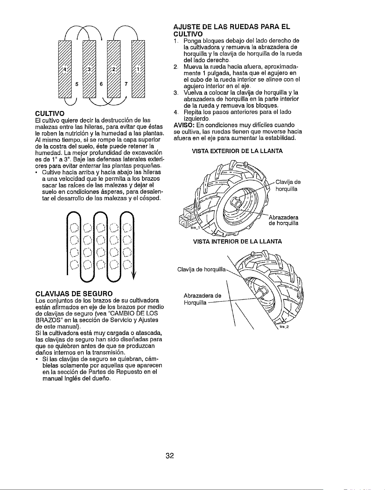
CULTIVO
Elcultivoquieredecirledestruccl6ndelas
malezasentrelashileres,pareevitarque_stas
lerobenlanutrici6ny tehumedadalas plantas.
AImismotiempo,si serompefacapesuperior
delacostrade!suelo,6stepuederetenerte
humedad.Lamejorprofundidaddeexcavaci6n
esde 1"a3".BejelesdefenseslateratesexterF
orespareevitarenterrarlesp!entaspequefias.
• Cultivehaciaarribay haciaabajolashileras
aunavelocidadquelepermitaalosbrazos
sacarlesreicesde !asmalezasy dejarel
sueloencondiciones&speras,paredeselen-
tareldeserroTIode lasmelezasy et c_spedo
J
,J .... L.;
C,IC ,L'J
CLAVIJAS DE SEGURO
Los conjuntos de los brazos de su cuitivadore
est&n afirmados en eje de los brazos por medio
de clevijas de seguro (vea "CAMBIO DE LOS
BRAZOS" en la secci6n de Servicto y Ajustes
de este manual),
Si la cultivadora est& muy cargada o atascada,
las clavijas de seguro hen sido diseSadas para
que se quiebren antes de que se produzcan
daSos internos en la transmisiSn,
• Si las clavijas de seguro se quiebren, c&m-
bielas solamente per aquellas que aparecen
en la secciSn de Partes de Repuesto en el
manual Ingles del duefio,
AJUSTE DE LAS RUEDAS PARA EL
CULTIVO
1. Ponga bloques debajo del lado derecho de
la cultivadora y remueve ta abrazadera de
horquille y ia clevija de horquille de le rueda
del lado derecho.
2, Mueva la rueda hecta afuera, aproximada-
mente 1 pulgeda, haste que el agujero en
el cubo de te rueda interior se elinee con el
agujero interior en el eje,.
3o Vuelva a colocar la clavija de horquilla y la
abrazedera de horquilla en la parte interior
de la rueda y remueva los bloques.
4. Repita los pasos anteriores pare el lado
izquierdo.
AVlSO: En condtciones muy dificiles cuando
se cultiva, las ruedas tienen que moverse hacia
afuera en el eje pare aumentar la estabIlidad.
VISTA EXTERIOR DE LA LLANTA
Clavija de
horquitla
razadera
e horquiHa
VISTA INTERIOR DE LA LLANTA
Clavija de horquitla_
AborrqZ_l_ae_
32
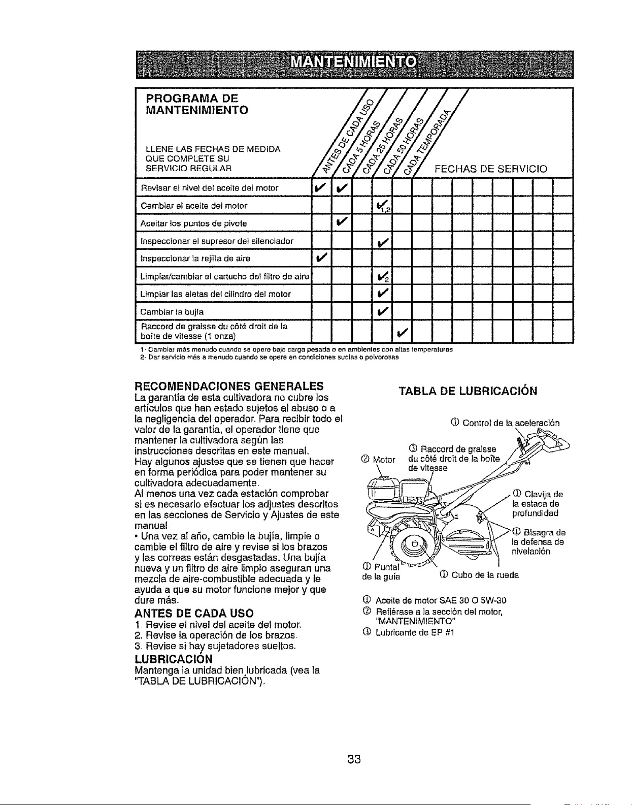
PROGRAMA DE
MANTENIMIENTO
QUE COMPLETE SU _ _' _ _ _ _'
SERVICIOREGULAR FECHAS DE SERVtCIO
Revisar el nivel det aceile del motor Ikf
Cambiar el aceite del motor 1_1.2
Aceitar los puntos de pivote I_ I
Inspecctonar el supresor det stlenciador if
Inspeccionarta rejilla da aire I_
Ltmplarlcambiar el cartuchodel filtrode aire 1_2
Llmptar las aletasdel cilindro del motor V'
Cambiar la buila i_
Raccord de graisse du c6t6 droit de la
boite de vitesse (I onza)
t - Cambtar m_s rrtenudo cuando se opera bajo carga pasada o en amblentes con alias lemperaluras
2- Dar servlcto m_s a menudo cuando se opera an condlcfones suclas o polvorosas
RECOMENDACIONES GENERALES
La,garantfa de esta cultivadora no cubre los
artlculos que han estado sujetos at abuso o a
la negligencia del operador. Para rectbir todo el
valor de la garantia, el operador tlene qua
mantener la cultivadora seg_n las
instrucciones descritas en este manual,
Hay algunos ajustes que se tienen que hacer
en forma peri6dica para poder mantener su
cultivadora adecuadamente,
AI menos una vez cada estaci6n comprobar
si es necesario efectuar los adjustes descritos
en las secciones de Servicio y Ajustes de este
manual.
• Una vez al aSo, cambie la bujJa, limpie o
cambie el filtro de atre y revise si los brazos
y las correas est&n desgastadaso Una bujJa
nueva y un filtro de aire limpio aseguran una
mezcla de aire-combustible adecuada y le
ayuda a,que su motor funcione mejor y qua
dure mas.
ANTES DE CADA usa
1. Revise el nivel del aceite del motor,
2, Revise Ia operaci6n de los brazos.
3. Revise si hay sujetadores sueltos°
LUBRICACI6N
Mantenga la unidad bien lubricada (vea ta
"TABLA DE LUBRICACION").
O Motor
• Punt_
de la guJa
TABLA DE LUBRICACION
O Control de la aceleracI6n
(_) Raccord de gralsse
du o5t6 drott de la boi'te
O Clavija de
la estaca de
profundldad
Blsagra de
la defensa de
ntvefaci6n
(I) Cuba de la rueda
O Aceite de motor SAE 30 O 5W-30
(_) Refi6rase a ]a secci6n del motor,
"MANTENtMIENTO"
O Lubrlcante de EP #1
33
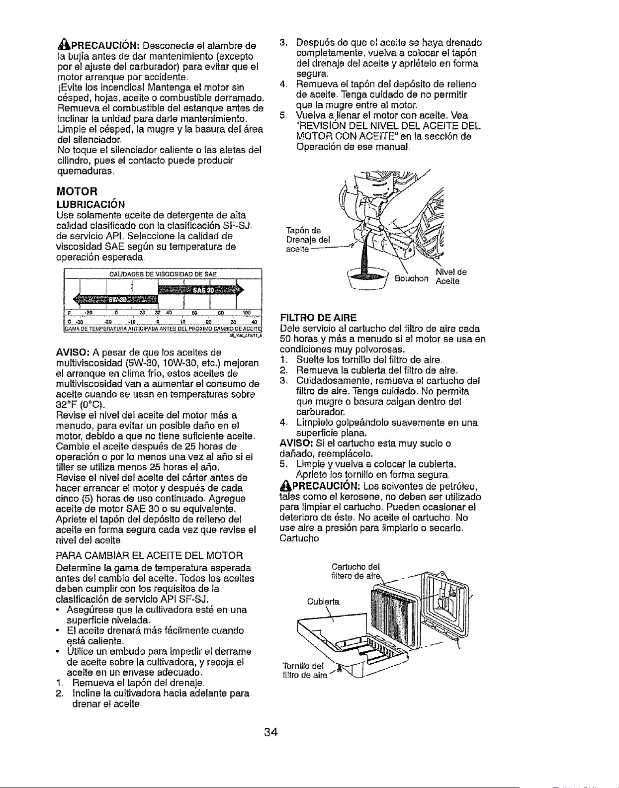
_,PRECAUCI6N: Desconecte el atambre de
la bujia antes de dar mantenimiento (excepto
por el ajuste del carburador) pare evitar que el
motor arranque por accldente.
IEvite los incendiosI Mantenga el motor sin
c_sped, hojas, aceite o combustible derramado.
Remueva el combustible del estanque antes de
incliner la unidad pare darle mantenimiento.
Umpie el c_sped, la mugre y la basura del &rea
del silenciador.
No toque el stlenciador caliente o tas aletas del
cilindro, pues el contacto puede producir
quemaduras.
MOTOR
LUBRlCACION
Use solamente aceite de detergente de atta
calidad clasificado con la clasificaci6n SF-SJ.
de servicio API, Seleccione la calidad de
viscosidad SAE seg_n su temperature de
operaci6n esperada.
AVISO; A pesar de que los aceites de
muitiviscosidad (5W-80, 1OW-30, etc.) mejoran
el arranque en clima frio, estos aceites de
multiviscosidad van a aumentar el consumo de
aceite cuando se usan en temperatures sobre
32°F (0°C)o
Revise el nivel de! aceite del motor m&s a
menudo, pare evitar un posible daSo en el
motor, debido a que no tiene suficiente aceite.
Cambie el aceite despu_s de 25 horas de
operaci6n o per Io menos una vez al aSo si el
tiller se utiliza menos 25 horas el aSo,
Revise el nivel del aceite del c&rter antes de
hacer arrancar el motor y despu_s de cada
cinco (5) horas de uso continuado. Agregue
acette de motor SAE 30 o su equivalenteo
Apriete el tap6n del depSsito de relleno del
aceite en forma segura cada vez que revise el
nivel del aceite.
PARA CAMBIAR EL ACEtTE DEL MOTOR
Determine la game de temperatura esperada
antes dei cambio del aceite. Todos los aceites
deben cumplir con los requisitos de la
clasificaci6n de servicio APt SF_SJ.
• AsegSrese que la cultivadora est_ en una
supefficie ntvelada.
• EI aceite drenar& m&s f&cilmente cuando
est,. caliente.
, Utilice un embudo para impedir el derrame
de aceite sobre la cultivadora, y recoja el
aceite en un envase adecuado_
1. Remueva el tap6n del drenaJe.
2. Incline la cultivadora hacia adelante pare
drenar el aceite.
3. Despu6s de que el aceite se haya drenado
completamente, vuelva a colocar el tap6n
det drenaje del aceite y apri_telo en forma
segura.
4_ Remueva et tap6n del dep6sito de relleno
de aceite_ Tenga cuidado de no permitir
que la mugre entre al motor.
5. Vuelva a Ilenar el motor con aceite. Vea
"REVISION DEL NWEL DEL ACEITE DEL
MOTOR CON ACEITE" en la secci6n de
Operaci6n de ese manual.
Tap6n de
Drenaje del
aceite
NIvel de
Bouchon Aceite
FILTRO DE AIRE
Dele servicio al cartucho del filtro de aire cada
50 horas y m&s a menudo si el motor se usa en
cond{ciones muy polvorosas.
1. Suelte los tornillo del filtro de aire_
2. Remueva la cubierta del filtro de aire.
3. Cuidadosamente, remueva el cartucho de{
filtro de aire_ Tenga cuidado. No permita
que mugre o basure caigan dentro det
carburador.
4. Limpielo golpe&ndolo suavemente en una
superficie plane,
AVISO: S1el cartucho esta muy sucio o
daSado, reempl&celoo
5, Limpie y vuelva a colocar la cubiertao
Apriete los tornil]o en forma segura_
A(_PRECAUCION: Los solventes de petr61eo,
tales como el kerosene, no deben set utilizado
para limpiar el cartucho. Pueden ocasionar el
deterforo de 6ste, No aceite el cartucho. No
use aire a presi6n pare limpiarlo o secarlo.
Cartucho
Cartucho del
Cubleda
Tornfllo det
fiftro de all
34
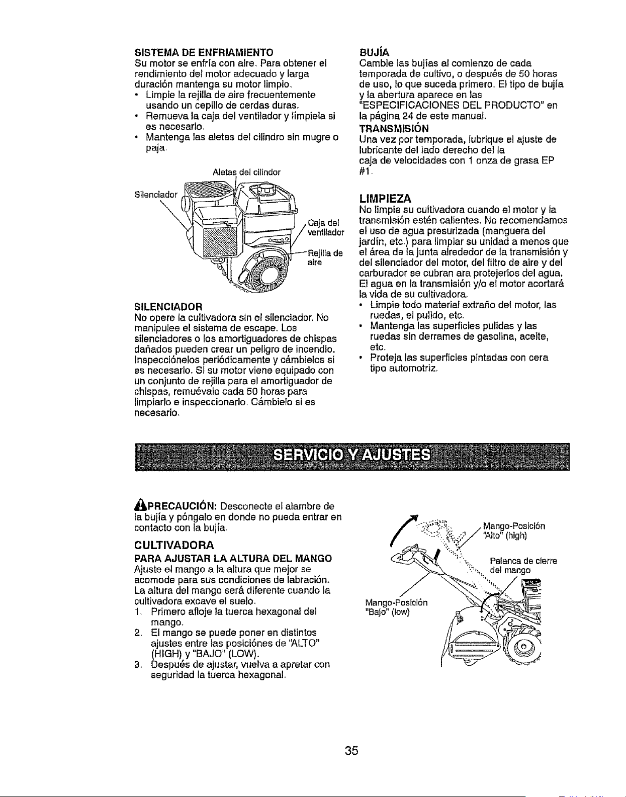
SISTEMA DE ENFRIAMIENTO
Su motor se enfr[a con aire. Para obtener el
rendimiento det motor adecuado y larga
duraci6n mantenga su motor limpio,
, Limpie [a rejilia de aire frecuentemente
usando un cepillo de cerdas duras,
• Remueva la caja del ventilador y iimpiela si
es necesario,
• Mantenga tas aletas det cilindro sin mugre o
paja.
Aletas del ciltndor
Stlenctador
\
SILENClADOR
No opere la cultivadora sin el silenciador. No
manipulee el sistema de escape, Los
silenciadores o los amortiguadores de chispas
dar_ados pueden crear un pel[gro de incendio,
Inspecci6nelos peri6dicamente y c&mbielos si
es necesario, SI su motor viene equipado con
un conjunto de rejitla para el amortiguador de
chispas, remu_valo cada 50 horas para
limpiarlo e inspeccionarlo, C&mbielo si es
necesario.
BUJiA
Camb}e las bujlas al comienzo de cada
temporada de cultivo, o despu_s de 50 horas
de uso, 1oque suceda primero. Et tipo de buj[a
y la abertura aparece en las
"ESPECIFICACIONES DEL PRODUCTO" en
la pfigina 24 de este manual,
TRANSMISION
Una vez per temporada, lubrique el ajuste de
lubricante del lado derecho della
caja de velocidades con I onza de grasa EP
#!-
LIMPIEZA
No limpie su cultivadora cuando el motor y la
transmisi6n est_n calientes, No recomendamos
el uso de agua presurtzada (manguera det
jardin, etc.) para limpiar su unidad a menos que
el &rea de la junta alrededor de ta transmiston y
del silenciador del motor, del filtro de aire y del
carburador se cubran ara protejedos del agua.
Et agua en la transmisi6n y/o el motor acortar&
la vida de su cultivadora,
• Limpie todo material extrafio del motor, las
ruedas, e! pulido, etc.
• Mantenga las superficies pu[idasy las
ruedas sin derrames de gasolina, aceite,
etc.
• Proteja las superficies pintadas con cera
tipo automotriz,
&_PRECAUCI6N: Desconecte el alambre de
la buj[a y p6ngalo en donde no pueda entrar en
contacto con la buj[a.
CULTIVADORA
PARA AJUSTAR LA ALTURA DEL MANGO
Ajuste el mango a ia altura que mejor se
acomode para sus condiciones de labraci6n.
La altura del mango ser& diferente cuando [a
cultivadora excave el suelo.
1. Primero afloje la tuerca hexagonal del
mango_
2, El mango se puede poner en distintos
ajustes entre las posici6nes de '_,LTO"
(HIGH) y "BAJO" (LOW).
3. Despues de ajustar, vuelva a apretar con
seguridad la tuerca hexagonal.
:.;_;;_:. .. Mango-Pos[ci6n
":_::._':,'_i..,,?_ '_lto" (high)
_:_._ 7!, Palancade cierre
35
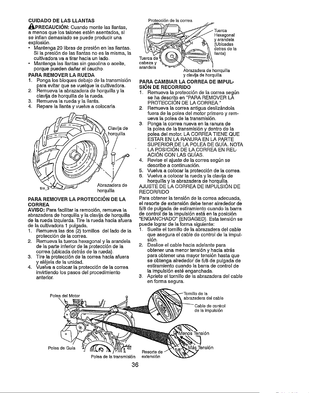
CUIDADO DE LAS LLANTAS
_PRECAUCI6N: Cuando monte tas llantas,
a menos que los talones est6n esentados, st
se inflan demasiado se puede productr una
explosiSn.
• Mantenga 20 libras de presi6n en las Ilantaso
Si la presi6n de las IIantas no es la misma, la
cultivadora va a tirar hacia un lade.
• Mantenga ias llantas sin gasolina o aceite,
porque pueden daSar el caucho.
PARA REMOVER LA RUEDA
1, Ponga los bloques debajo de la transmisiSn
para evitar que se vuelque la cultivadorao
2_ Remueva la abrazadera de horquilla y la
clavija de horquilla de la rued&
& Remueva la rueda y la tlanta,
4. Repare la llanta y vuelva a colocarla.
Clavija de
Abrazadera de
tire3 horquiIla
PARA REMOVER LA PROTECCION DE LA
CORREA
AVISO: Para facititar la remoci6n, remueva la
abrazadera de horquilla y la clavija de horquilla
de la rueda izquierda. Tire Jarueda hacia afuera
de la cultivadora 1 pulgada_
I, Remueva las dos (2) tomiltos del lade de la
protecci6n de ia corre&
2, Remueva la tuerca hexagonal y la arandela
de la parte inferiorde la protecct6n de la
correa (ubicada detr&s de ta rueda).
3, Tire la protecci6n de la correa hacia afuera
y al_jela de la unidad,
4_ Vuelva a colocar la protecciSn de la correa
invirtiendolos pasos del procedimiento
anterior.
Polea de! Motor
Protecot6nde Iacorrea
_Tuerca
:./-_z_.f He×agonat
"_. y arandeta
_ "t_ (Ublcadas
\\ detrasde la
Tu IEanta)
cabeza y _'_'_-"_
arandeta
Abrazaderade horrquilla
y cfavlja de horquilla
PARA CAMBIAR LA CORREA DE IMPUL-
SION DE REGORRIDO
1, Remueva la protecci6n de ta correa segt_n
se ha descrito en "PARA REMOVER LA
PROTECCION DE LA CORREA."
2 Remueva la correa antigua desliz&ndo]a
fuera de la polea del motor p!imero y rem-
ueva la polea de la transmiston_
3, Ponga la correa nueva en la ranura de
la polea de la transmist6n y dentro de la
polea del motor, LA CORREA TtENE QUE
ESTAR EN LA RANURA EN LA PARTE
SUPERIOR.DE LA POLEA DE GUIA, NOTA
LA POSICION DE LA CORREA EN REL-
ACION CON LAS GUiAS.
4. Revise el ajuste de la correa segt_n se
describe a continuaciSno
5o Vuelva a co!ocar la proteccidn de la correa,
6.. Vuelva a colocar ta rueda y la ctavija de
horquilla y la abrazadera de horquilla.
AJUSTE DE LA CORREA DE IMPULSION DE
RECORRIDO
Para obtener la tensiSn de ta correa adecuada,
el resorte de extensiSn debe tener alrededor de
5/8 de pulgada de estlramfento cuando la barra
de control de la impulsi6n est& en la posiciSn
"ENGANCHADO" (ENGAGED), Esta tensidn se
puede lograr de la forma siguiente:
1. Suelte el tornillo de la abrazadera del cable
clue asegura el cable de control de ]a impul-
siorl.
2. Deslice el cable hacia adelante para
obtener una mener tensi6n y hacia atr&s
para obtener una mayor tensi6n hasta que
se obtenga alrededor de 5/8 de pulgada de
estiramiento cuando la barra de control de
la }mpulsi6n est_ enganchada.
3. Apdete el tornillo de la abrazadera del cable
en forma segura.
de la
abrazadera del cable
}trol
de la tmpulsi6n
Tensi6n
Polea de Guia
Poleade la transmisl6n
36
Resorte de
extenst6n
M&sTensi6n
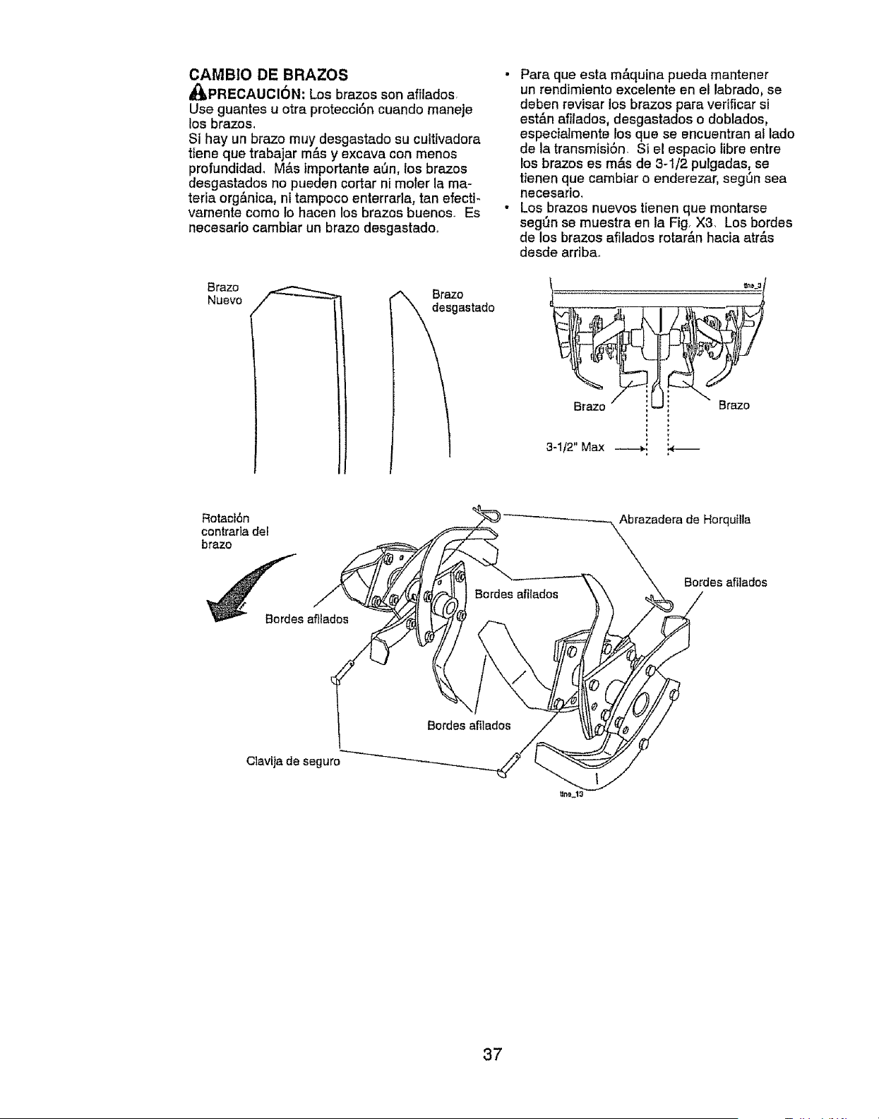
CAMBIO DE BRAZOS
_PRECAUCI6N: Los brazos son afilados
Use guantes u otra protecci6n cuando maneje
los brazos,
Si hay un brazo muy desgastado su cuttivadora
tiene que trabajar m&s y excava con menos
profundida& Mas Importante aun, los brazos
desgastados no pueden cortar ni moler la ma-
teria org&nica, ni tampoco enterrarla, tan efecti-
vamente como 1ohacen los brazos buenos. Es
necesario camblar un brazo desgastado.
Brazo
Nuevo
_es Braz°
gastado
• Para que esta m&quina pueda mantener
un rendimiento excelente en et labrado, so
deben revisar los brazos para verificar si
est_.n afilados, desgastados o doblados,
especiaimente los que so encuentran al lado
de la transmisi6n. Si el espacio tibre entre
los brazos es m&s de 3-1/2 putgadas, se
tienen que cambiar o enderezar, seg_n sea
necesario,
• Los brazos nuevos tienen que montarse
segt_n se muestra en la Fig, X3, Los bordes
de los brazes afilados rotar&n hacia etr&s
desde arriba.
Brazo Brazo
3-1/2" Max
Rotaot6n
contraria del
brazo
Abrazadera de Horqutlta
Bordes afilados
Clavija de seguro
37
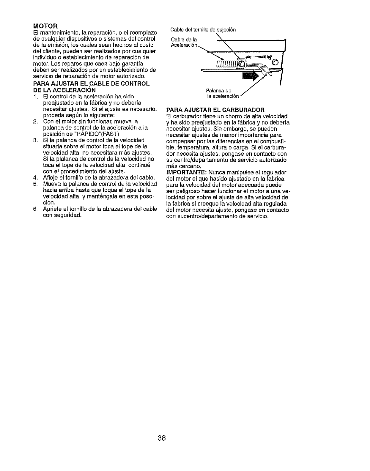
MOTOR
Et mantenimiento, la reparaci6n, o el reemplazo
de cualquier dispositivos o sistemas del control
de ta emisi6n, los cuales seen hechos al costo
del ctiente, pueden ser reatizados pot cualquier
individuo o establecimiento de reparaci6n de
motor. Los reparos que caen bajo garant[a
deben ser realizados por un establecimiento de
servicio de reparaci6n de motor autorizado.
PAFIA AJUSTAR EL CABLE DE CONTROL
DE LA ACELERACION
1. El control de la aceleraci6n ha sido
preajustado en la f&brice y no deberia
necesitar ajustes. Si el ajuste es necesario,
proceda seg_n lo siguiente:
2. Con el motor sin funcionar, mueva la
palanca de control de la aceleraci6n a Ja
posici6n de "RAPIDO"(FAST).
3. Si la palanca de control de la velocidad
situada sobre ei motor toce et tope de la
vetoctdad alia, no necesitara m&s ajustes.
Si la plalanca de control de la velocidad no
toca el tope de la velocidad alia, continu6
con el procedimiento del ajusteo
4. Afloje el tornillo de la abrazadera del cable.
5o Mueva la palanca de control de la ve!ocldad
hacia arriba hasta qua toque el tope de la
vetoctdad alia, y mant_ngala en esta poso-
ci6n.
6, Apriete el torntllo de la abrazadera del cable
con seguridad,
Cable del torntllo de sujeci6n
CabEede la
Palanca de
ia aceleraci6n
PARA AJUSTAR EL CARBURADOR
El carburador tiene un chorro de alta velocidad
y ha sido preajustado en la f&brica y no debede
necesitar ajustes. Sin embargo, se pueden
necesitar ajustes de manor importancia pare
compensar per las diferencias en et combusti-
ble, temperature, altura o carge. Si el carbura-
dor necesita ajustes, pongase en contacto con
su centro/departamento de servicio autorizedo
m&s cercano.
IMPORTANTE: Nunca maniputee el regulador
del motor el qua hasldo ajustado en la fabrica
pare la velocidad del motor adecuada puede
ser pellgroso hacer funclonar el motor a una ve-
Iocidad por sobre el ajuste de alia velocidad de
la fabrtce si creeque la velocidad alia regulada
del motor necesita ajuste, pongase en contacto
con sucentro/departamento de servicio.
38
inmediatamente prepare su cuttivadora para e!
almacenamiento at final de la temporada o si la
unidad no se va a usar por 30 dfas o m&s.
_,PRECAUCl6N: Nunca almacene la cuttiva-
dora con gasolina en el estanque dentro de un
edificio en donde los gases pueden alcanzar
una Itama expuesta o una chispa. Permita que
el motor se enfrie antes de almacenarlo en
cualquier recinto privado.
CU LTIVADORA
1, Limpie toda la cultivadora (vea "LIMPIEZA"
en la secci6n de Mantenimiento en este
manual).
2o Inspeccione y cambie las correas, si es
necesario (yea las instrucciones para el
cambio de la correa en la secci6n de Ser¢i-
cto y Ajustes de este manual),
3. Lubriquela seg_n se muestra en la secci6n
de Mantenimiento en este manual
4. AsegSrese que todas las tuercas, pernos y
tornillos est_n apretados en forma segura,
Inspeccione las partes movibles para verifi-
car si est&n dar_adas, rotas o desgastadas,
C&mbielas si es necesario.
5. Retoque tedas las superficies pintadas
que est_n oxidadas o picadas; use una lija
suavemente antes de pintar.
MOTOR
SISTEMA DE COMBUSTIBLE
IMPORTANTE: Es importante evitar que se
formen dep6sitos de goma en partes funda_
mentales del sistema de combustible tales
como el carburador, el flltro del combustible,
la manguera del combustible o en el estanque
durante el almacenamiento, La experiencla
tambi_n indica que los combustibles mezclados
con alcohol (conocido como gasohol o que
tienen etanol o metanol) pueden atraer hume-
dad, Io que conduce a la separaci6n de &cidos
durante e! almacenamiento. La gasotina &cidica
puede daSar el sistema de combustible de un
motor durante el periodo de almacenamiento.
• Vaciar el dep6sito del carburante poniendo
en marcha el motor y dej&ndolo funcionar
hasta que el carburante termine el carbura-
dor est_ vacfo,
. Nunca use los productos para limpieza del
carburador o del motor en el estanque de
combustible pues se pueden producir daSos
permanentes,
• Use combustible nuevo la pr6xima tempo-
rada.
AVISO: El estabitizador de combustible es una
alternativa aceptable para reducir a un minimo
la formaci6n de dep6sitos de goma en el com-
bustible durante el periodo de almacenamiento
Agregue estabilizador a ta gasolina en el
estanque de combustible o en el envase para
el almacenamiento. Siempre siga fa proporci6n
de mezcla que se encuentra en el envase
del estabilizador. Haga funcionar el motor por
Io menos 10 minutos despu_s de agregar el
estabilizador, para permitir que _ste llegue al
carburador. No vaciar la gasolina del estanque
de gasolina y el carburador si se est,. usando
estabilizador de combustible°
ACEITE BEL MOTOR
Drene el aceite (con el motor caliente) y
c&mbie{o con aceite de motor !impio. (Vea "MO-
TOR" en la secci6n de Mantenimiento de este
manual.)
CILINDRO(S)
1o Remueva la bujia.
2. Vacie una onza de aceite a trav_s de! agu-
jero de la bujia en el cilindro,
3, Tire el mango del arrancador, lentamente,
varias veces para distribuir el aceite,
4. Cambie por una bujfa nueva.
OTROS
• No guarde la gasolina de una temporada a ta
otrao
, Cambie el envase de la gasolina si se emp-
ieza a oxidar. La oxidaci6n yio la mugre en
su gasolina producir&n problemas.
• Si es posible, guards su unidad en un recinto
cerrado y c6brala para protegeda contra el
polvo y la mugre.
• Cubra su unidad con un forro protector
adecuado que no retenga la humedad° No
use pt&stico. EI pl&stico no puede respirar, Io
que permite la formaci6n de condensaci6n,
Io que producir& la oxidaci6n de su unidad.
IMPORTANTE: Nunca cubra la cultivadora
mientras el motor y las areas de escape toda-
via estan calientes.
39
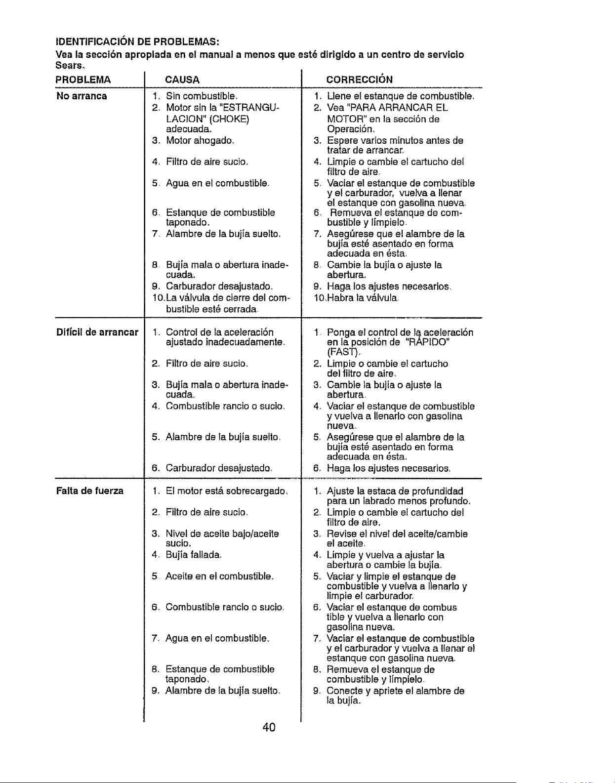
IDENTIFICACION DE PROBLEMAS:
Vea la seccibn apropiada en el manual a menos que est6 dirtgido a un centro de servicio
Sears,
PROBLEMA
No arranca
Dificil de arrancar
Faita de fuerza
CAUSA
1. Sin combustible.
2. Motor sin la"ESTRANGU-
LACION" (CHOKE)
adecuada.
3. Motor ahogado.
4. Fiftro de aire sucio.
5. Agua en el combustible.
6. Estanque de combustible
taponado.
7. Alambre de la bujia suelto.
8 Bujia male o abertura inade-
cueda°
9. Cerburador desajustedo_
10.La v&tvula de cierre del com-
bustible est6 cerrada_
1. Control de la aceleraciSn
ajustado inadecuadamente.
2. Filtro de aire sucio.
3o Bujia male o abertura inade-
cued&
4. Combustible rancio o sucio.
5_ Alambre de la bujia suelto.
6o Cerburador desejustado.
1. El motor est& sobrecargado.
2. Filtro de eire sucio.
3. Nivel de eceite bajo/aceite
sucio.
4. Bujia fallada.
5 Aceite en el combustible.
6.. Combustible rancio o sucio.
7. Ague an el combustible..
8. Estanque de combustible
taponado.
9. Alambre de la bujta suelto.
CORRECCION
1. Llene el estanque de combustible.
2. Vea "PARA ARRANCAR EL
MOTOR" en la secci6n de
Operaci6n°
3o Espere varios minutos antes de
tretar de arrancar_.
4. Limpie o cambie el cartucho del
filtro de aire.
5. Vaciar et estanque de combustible
y el carburador, vuelve e Ilenar
el estanque con gasoline nueve.
6. Remueva el estanque de com-
bustible y limpielo.
7. Asegt'Jrese qua el alambre de la
bujta est_ asentado en forma
adecuada en esta
8. Cambie ta bujta o ajuste la
abertura.
9. Hege los ajustes necesarios.
10.Habra la v&lvuFa_
1. Ponga el control de I_ acelereci6n
ente posici6n de "RAPIDO"
(FAST).
2. Limpie o cambie el cartucho
de! filtro de eire.
3. Cambie la bujia o ajuste la
abertura.
4. Vaciar el estanque de combustible
y vueiva a Ilenerlo con gasoline
nueva.
5, Aseg{]rese qua el alambre de la
bujla este asentado en forme
adecuada en _ste,
6_ Haga los ajustes necesarios,
1_ Ajuste la estaca de profundidad
para un labrado menos profundoo
2. Limpie o cambte ei cartucho del
filtro de atre.
& Revise e! nivel det aceiteicambie
el eceite,
4_ Limpie y vuelva e ajustar le
aberture o cembie la bujfa,
5, Vacier y limpie el estanque de
combustible y vuelve a llenarto y
timpie el carburador.
6, Vacier el estanque de combus
tibia y vuelva a Ilenarlo con
gasotina nuevao
7o Vaciar el estanque de combustible
y el carburedor y vuelva a Uener el
estanque con gasolina nueva.
8, Remueva el estanque de
combustible y limpielo,
9, Conecte y apriete el alambre de
le bujia.
40
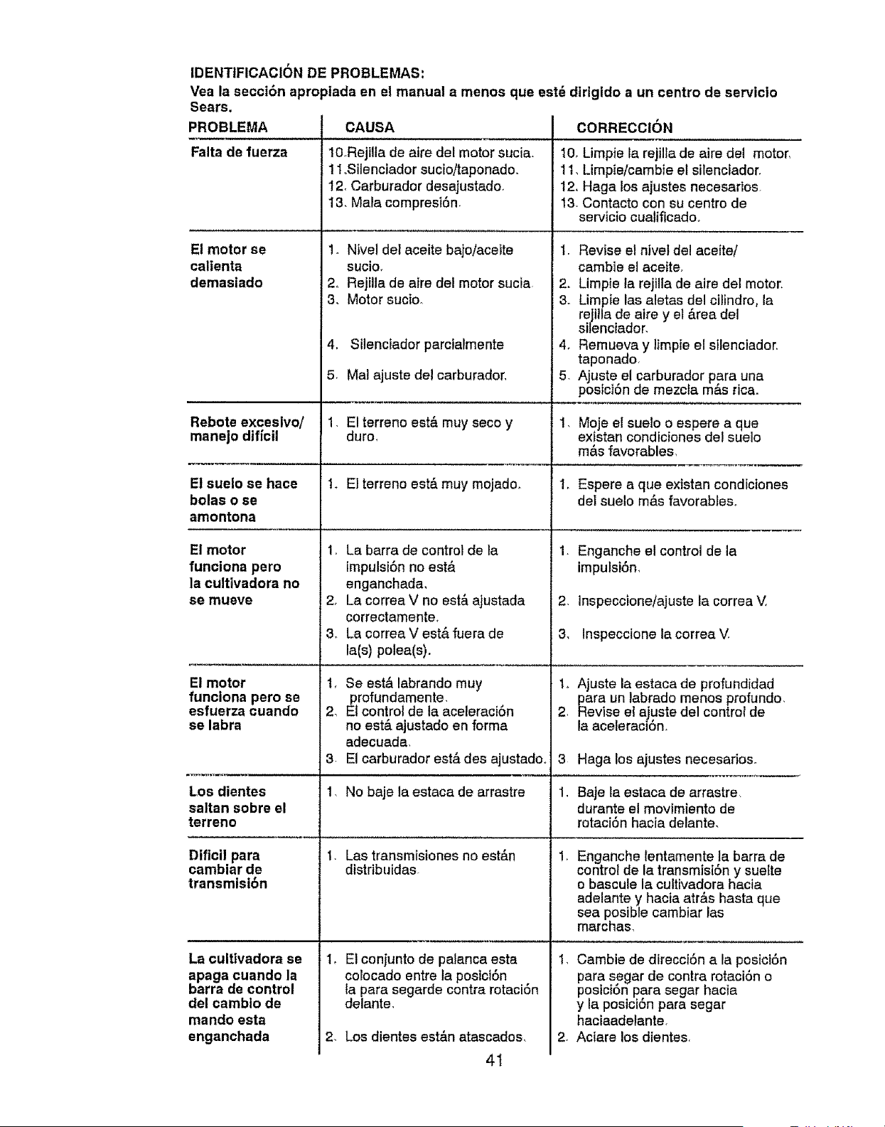
IDENTIFICACION DE PROBLEMAS:
Vea la secci6n apropiada en el manual a menos que est_ dtrigido a un centro de servic|o
Sears.
PROBLEMA
Falta de fuerza
El motor se
caltenta
demasiado
Rebote exceslvo/
manejo dificil
El suelo se hace
bolas o se
amontona
E! motor
funciona pero
la culttvadora no
se mueve
El motor
funciona pero se
esfuerza cuando
se labra
Los dientes
saltan sobre el
terreno
Dificil para
cambiar de
transmlsi6n
La cultivadora se
apaga cuando la
barra de control
del camblo de
mando esta
enganchada
CAUSA
10oRejilla de aire del motor sucia.
11oSitenciador sucio/taponado.
12. Carburador desajustado.
13_ Mala compresiSn
1. Nivel del aceite bajoiaceite
sucio_
2, Rejilla de aire del motor sucia
3, Motor sucio,
4. Silenciador parcialmente
5. Mal ajuste del carburador,
1. El terreno est& muy seco y
duro,
i. E1terreno est& muy mojado,
1. La barra de control de la
tmpulsi6n no est,,
enganchada,
2_ La correa V no est& ajustada
correctamente_
3_ La correa V est,. fuera de
la(s) polea(s).
t, Se est& labrando muy
profundamente,
2, El control de la aceleraciSn
no est& ajustado en forma
adecuada.
3 El carburador est_ des ajustado.
1. No baje la estaca de arrastre
t. Las transmistones no est&n
distribuidas
to E1conjunto de palanca esta
colocado entre fa postci6n ,
fa para segarde contra rotacion
clelante,
2_ Los dientes est&n atascados.
CORRECCION
10, Limpie la rejilla de aire de1 motor,
11_Limpie/cambie et silenciador.
12, Haga los ajustes necesarIos.
13 Contacto con su centro de
servicio cualiflcadoo
I. Revise e! nivel del ace|re/
cambie el aceite.
2. Limpie ta rejilfa de aire del motor,
3. Limpie las aletas del cilindro, la
rejtlla de atre y el &rea dei
silenciador.
4. Remueva y limpie el silenclador.
taponado.
5. Ajuste el carburador para una
postcton de mezcla mas rica.
1, Moje el sue_o o espere a que
existan condiciones de! suelo
m&s favorables,
1, Espere a que existan condiciones
del suelo m&s favorables°
1. Enganche el control de la
impulsiSn,
1, Ajuste la estaca de profundidad
para un labrado menos profundo.
2. Revise el ajuste del control de
la aceleracion_
3 Haga los ajustes necesarios.
1, Baje la estaca de arrastre
durante el movimiento de
rotaci6n hacia delante.
Enganche lentamente la barra de
control de la transmisi6n y suelte
o bascule la cultivadora hacia
adelante y hacia atr&s hasta que
sea posible cambiar las
marchas,
I, Cambie de direcci6n a la posici6n
para segar de contra rotaci6n o
posict6n para segar hacia
y la posicion para segar
haciaadelante.
2. Aciare los dientes.
41
2. Inspeccione/ajuste la correa V,
3, Inspeccione ta correa V.
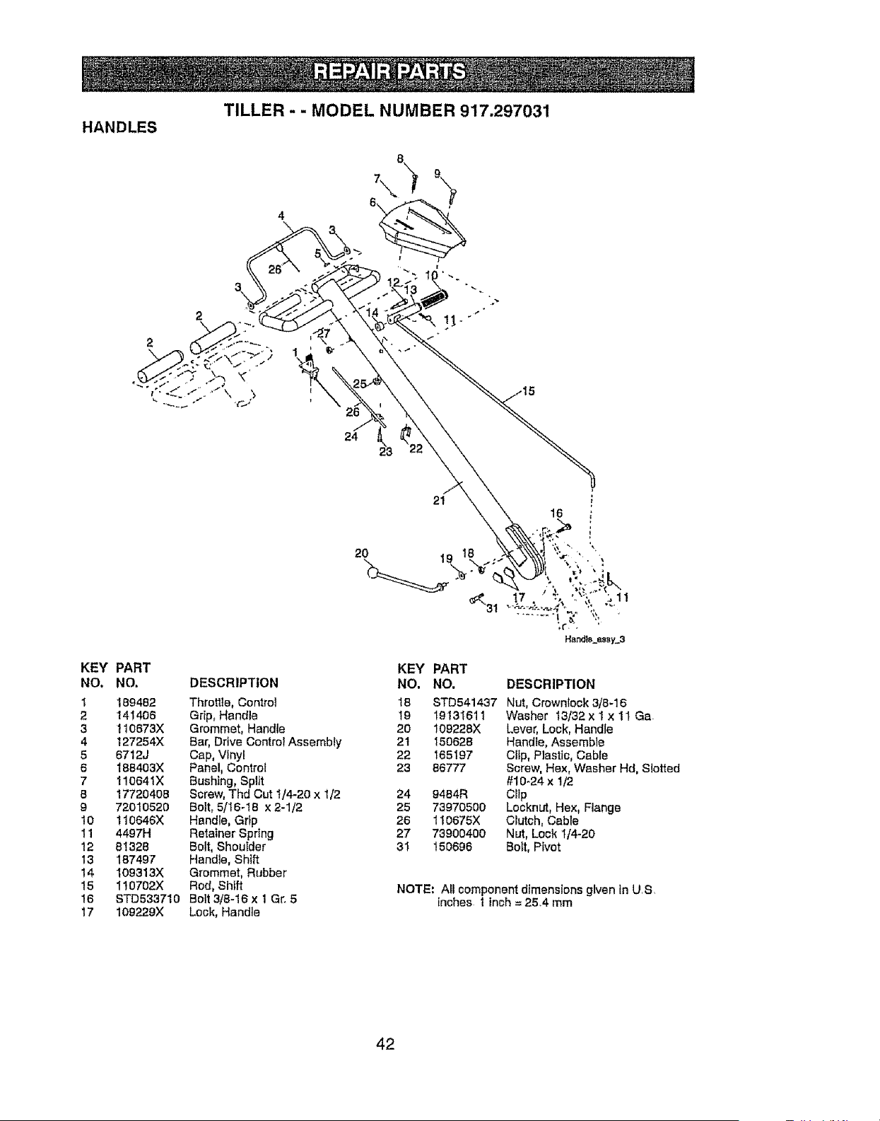
TILLER - - MODEL NUMBER 917.297031
HANDLES
2
26
24
KEY PART
NO, NO.
1 189482
2 141406
3 110673X
4 127254)(
5 6712J
6 188403X
7 110641X
8 17720408
9 72010520
10 110646X
11 4407H
12 81328
13 187407
!4 109313X
15 110702X
16 STD533710
17 109229X
DESCRIPTION
Throttle, Control
Grip, Handle
Grommet, Handle
Bar, Drive Control Assembly
Cap, Vinyl
Panel, Control
Bushing, Split
Screw, Thd Cut 1/4-20 x 1/2
Bolt, 5/16-I8 x 2-1/2
Handle, Grip
Retainer Spring
Bolt, Shoulder
Handle, Shift
Grommet, Rubber
Rod, Shift
Bolt 3/8-16 x 1 Gr, 5
Lock, Handle
2O
21
19
KEY PART
NO. NO. DESCRIPTION
18 STD541437 Nut. Crownleck 3/8-16
19 19131611 Washer t3/32 x 1 x 11Ga
20 109228X Lever, Lock, Handie
21 150628 Handle, Assembte
22 165197 Cltp, Plastic, Cable
23 86777 Screw, Hex, Washer Hd, Slotted
#I0_24 x 1/2
24 0484R C!tp
25 73970500 Locknut, Hex, Flange
26 110675X Ciutch, Cable
27 73900400 Nut, Lock 1/4-20
31 150696 Belt, Pivot
NOTE: AII componentdimensions given in UrS,
inches 1 tnoh= 25,4 mm
42
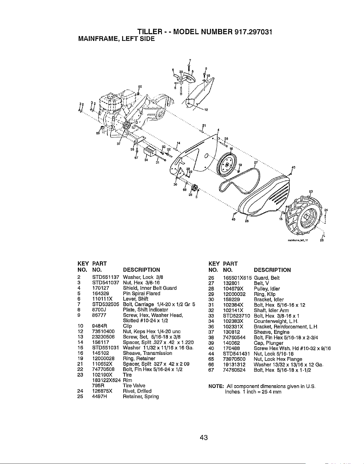
TILLER - - MODEL NUMBER 917.297031
MAINFRAME, LEFT SIDE
KEY PART
NO. NO,
2 STD551137
3 STD54t037
4 170127
5 164329
6 110111X
7 STD532605
8 8700J
9 86777
10 9484R
12 73510400
13 23230506
14 156117
15 8TD651031
16 145102
10 12000028
21 t10652X
22 74770508
23 t021g0x
183122X624
795R
24 I26875X
25 4497H
DESCRIPTION
Washer, Lock 3/8
Nut, Hex 3/8-16
Shield, inner Belt Guard
Pin Spiral Flared
Lever, Shift
Bolt, Carriage 1/4-20 x 1/2 Gr 5
Plate, Shift Indicator
Screw, Hex, Washer Head,
Slotted #I0-24x I/2
Clip
Nut, Keps Hex 1/'4-20 unc
Screw, Set, 5/16-18 x 3/8
Spacer, Split .327 x .42 x 1.220
Washer 11/32 x 1t/16 x 16 Ga.
Sheave, Transmission
Ring, Retainer
Spacer, Split 327x 42 x209
Belt, Fin Hex 5/16-24 x 1/2
Ttre
Rim
Tire Valve
Rivet, Drilled
Retainer, Spring
KEY
NO,
26
27
28
29
30
31
32
33
34
36
37
38
39
40
44
65
66
67
PART
NO. DESCRIPTION
165501X615 Guard, Belt
132801 Beft, V
I04679X Pulley, Idier
12000032 Ring, Klip
159229 Bracket, Idler
102384X Bolt, Hex 5/16-16 x 12
102141X Shaft, idler Arm
STD523710 Bolt, Hex 3/8-16 x 1
102383X
102331X
130812
74760544
140062
170468
STD541431
73970500
19131312
74760524
Counterweight, LH
Bracket, Reinforcement, L.H
Sheave, Engine
Bolt, Fin Hex 5/16-18 x 2-3/4
Cap, Plunger
Screw Hex Wsh. Hd #10-32 x 9/16
Nut, Lock 5/16_18
Nut, Lock Hex Flange
Washer 13/32 x 13/16 x 12 Ga.
Bolt, Hex 5/16-18 x 1-1/2
NOTE: Ali component dimensions given in US.
Inches 1 inch = 254 mm
43
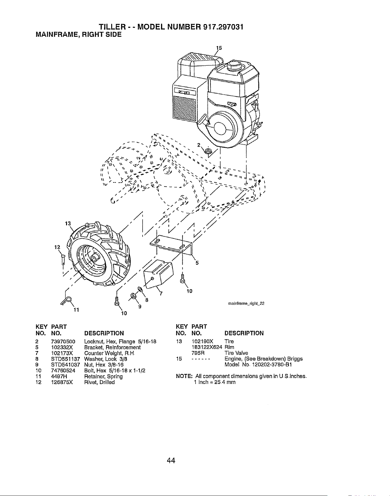
TILLER - - MODEL NUMBER 917.297031
MAINFRAME, RIGHT SIDE
15
12
,/
KEY PART
NO, NO. DESCRIPTION
2 73970500 Locknut, Hex, Flange 5116-1B
5 102332X Bracket, Retnfomement
7 102!73X CounterWeight, R,H,
8 STD551137 Washer, Lock 3/5
9 STD541037 Nut, Hex 3/8_16
10 74760524 Bolt, Hex 5116-18 x I-1/2
11 4497H Retainer, Spring
12 126875X Rivet, Drilled
KEY PART
NO. NO. DESCRIPTION
13 102t90X Tire
183122X624 Rim
795R Tire Valve
15 ...... Engine, (See Breakdown) Briggs
Model No- 120202-3780-B1
NOTE: All component dimensions given in US,Inches,
I inch = 25,4 mm
44
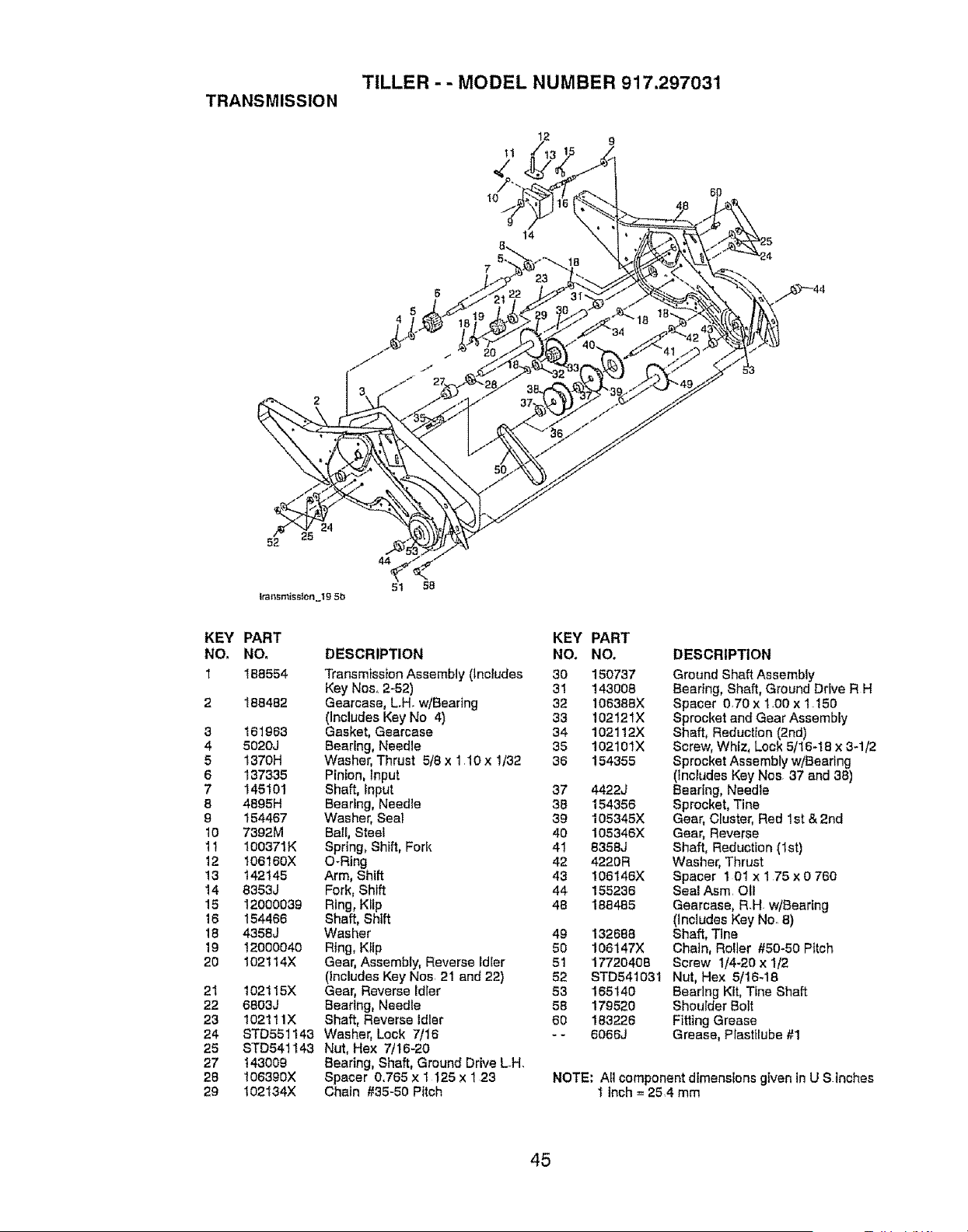
TILLER - - MODEL NUMBER 917.297031
TRANSMISSION
lO
14
7
6
4
KEY
NO.
I
2
3
4
5
6
7
8
9
IO
11
12
13
14
15
16
18
19
2o
21
22
23
24
25
27
2B
29
24
52
tral_smiss{on_Ig 5b
44
51 58
PART KEY PART
NO. DESCRIPTION NO, NO,
168554 Transml_sslonAssembly (Includes 30 150737
Key Nos, 2-52) 31 143008
188482 Gearcase, LH. w/Bearing 32 106368X
(Includes Key No 4) 33 102121X
161963 Gasket, Gearcase 34 102112X
5020J Beating, Needle 35 102101X
1370H Washer, Thrust 5/5 x 1.10 x 1/32 36 154355
137335 Pinion, input
145101 Shaft, input 37 4422J
4695H Bearing, Needle 36 154356
154467 Washer, Seal 39 105345X
7392M Bali, Steel 40 105346)(
100371K Spring, Shift, Fork 41 8358J
106160X O-Ring 42 4220R
142145 Arm, Shift 43 106146X
8353J Fork, Shift 44 155236
12000039 Ring, Kflp 48 186485
154466 Shaft, Shtft
4358J Washer 49 132688
12000040 Rtng, Kflp 50 106147X
102t 14X Gear, Assembly, Reverse idler 51 17720408
(includes Key Nos 21 and 22) 52 STD541031
102t 15X Gear, Reverse Ldler 53 165140
6803J Bearing, Needle 58 179520
102111X Shaft, Reverse idler 60 183226
STD551t43 Washer, Lock 7/'16 -- 6066J
STD541143 Nut, Hex 7/16-20
143009 Bearing, Shaft, Ground Drive LH.
t06390X Spacer 0.765 x 1125 x 123
102134)( Chain #35-50 Pitch
DESCRIPTION
Ground Shaft Assembly
Bearing, Shaft, Ground Drive R H
Spacer 070 x 1.00 x 1.150
Sprocket and Gear Assembty
Shaft, Reduction (2nd)
Screw, Whiz, Lock 5f16-18 x 3-1 t2
Sprocket Assembly w/Bearing
(Includes Key Nos 37 and 38)
Bearing, Needle
Sprocket, Tine
Gear, Cluster, Red 1st & 2rid
Gear, Reverse
Shaft, Reduction (1st)
Washer, Thrust
Spacer 1 01 x 175 x 0 760
Sea_ Asm. OIf
Gearcase, R.H w/Bearing
(Includes Key No. 8)
Shaft, Tlne
Chain, Roller #50-50 Pitch
Screw 114-20 x 1/2
Nut, Hex 5/16-18
Bearing Kit, Tine Shaft
Shoulder Bolt
Fitting Grease
Grease, Piasttlube #1
NOTE: All component dimensions given in U S inches
1 inch = 25 4 mm
45
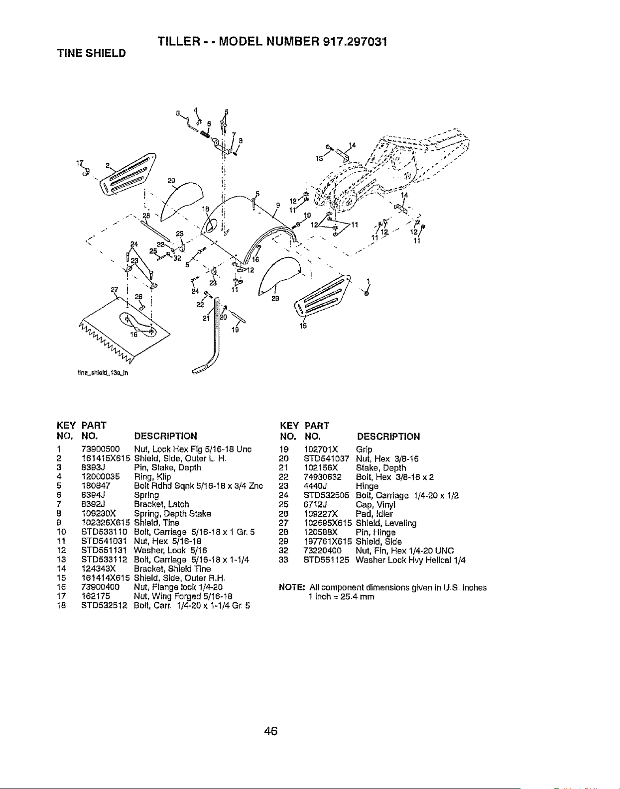
TINE SHIELD
TILLER - - MODEL NUMBER 917.297031
lin___h!elcL_3_Ljn
2g
7
8
019_ 15
14
11i 11
KEY PART
NO. NO.
1 73900500
2 1614t5X615
3 8393J
4 12000035
5 180847
6 8394J
7 8392J
8 109230X
9 102326X615
10 STD5331t0
11 STD541031
12 STD551131
13 STD533112
14 124343X
15 161414X615
!6 73900400
17 162175
18 STD532512
KEY PART
DESCRIPTION NO. NO.
Nut, Lock Hex Fig 5/16-15 Unc 19 102701X
Shield, Side, Outer L.H. 20 8TD54t037
Pin, Stake, Depth 21 102156X
Ring, Klip 22 74930632
Bolt Rdhd Sqnk 5/16-18 x 3/4 Znc 23 4440J
Spring 24 STD532505
Bracket, Latch 25 6712J
Spring, Depth Stake 26 109227X
Shield, Tine 27
Bolt, Carriage 5/16-18 x I Gr. 5 28
Nut, Hex 5/16-18 29
Washer, Lock 5/16 32
Bolt, Carriage 5/16-18 x 1-t/4 33
Bracket, Shield Tine
Shield, Side, Outer R.H
Nut, Range lock 1/4-20
Nut, Wing Forged 5/16-t8
Bolt, Cart. 1/4-20 x 1-1/4 Gr. 5
DESCRIPTION
Grip
Nut, Hex 3/8-16
Stake, Depth
Bolt, Hex 3/8-16 x 2
Hinge
Bolt, Carriage 1/4420 x tt2
Cap, Vinyl
Pad, Idler
102695X615 Shield, Leveling
120588X Pin, Hinge
197761X615 Shield, Side
73220400 Nut, Fin, Hex 1/4-20 UNC
STD551125 Washer Lock Hvy Helical 1/4
NOTE: All component dimensions glven In U.S. Inches
1 Inch = 25.4 mm
46
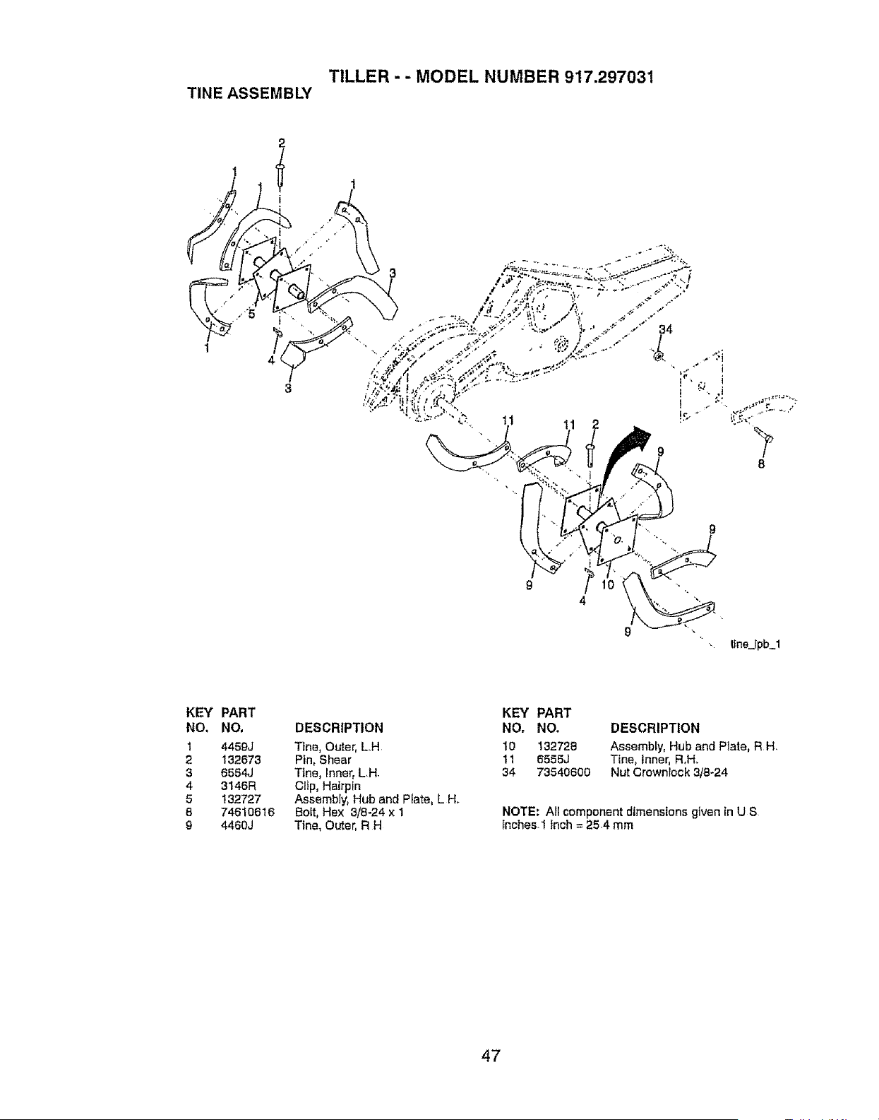
TILLER - - MODEL NUMBER 917.297031
TINE ASSEMBLY
1
11
KEY PART
NO, NO.
1 4459J
2 132673
3 6564J
4 3146R
5 132727
8 74610616
9 4460J
DESCRIPTION
TiRe, Outer, L.H
Pin, Shear
TiRe, Inner, LH.
Cilp, Hairptn
Assembly, Hub and Plate, L Ho
Bolt, Hex 3/8-24 x 1
Tine, Outer, R H
KEY PART
NO, NO. DESCRIPTION
10 132728 Assembly, Hub and PIate, RH.
11 6555J Tine, Inner, R,H.
34 73540600 Nut Crowniock 3/8-24
NOTE: All component dimensions given tn U S
Inches.1 inch = 25.4 mm
47
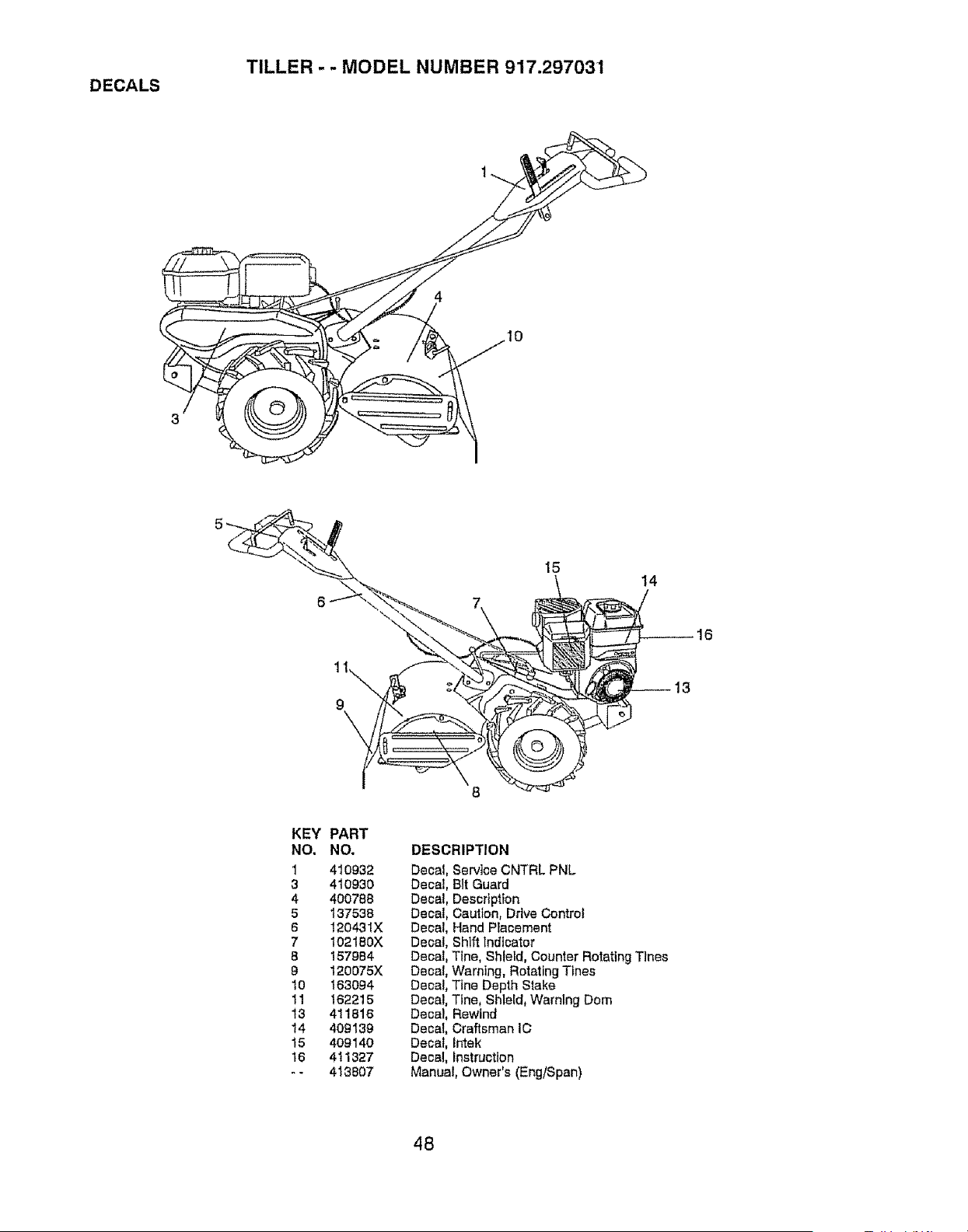
DECALS
TILLER - - MODEL NUMBER 917.297031
8
14
KEY PART
NO, NO. DESCRIPTION
1 410932 Decal, Service CNTRL PNL
3 410930 Decal, Bit Guard
4 400788 Decal, Description
5 137538 Decal, Caution, Drive Control
6 12043tX Decal, Hand Placement
7 102180X Decal, Shift Indicator
8 157984 Decal, Ttne, Shield, Counter Rotating Tines
9 120075X Decal, Warning, Rotating Tines
10 163094 Decal, Tfne Depth Slake
11 162215 Decal, Tfne, Shield, Warning Dom
13 411816 Decal, Rewind
14 409139 Decal, Craftsman IC
15 409140 Decal, intek
16 411327 Decal, instruction
- - 413807 Manual, Owner's (Eng/Span)
48
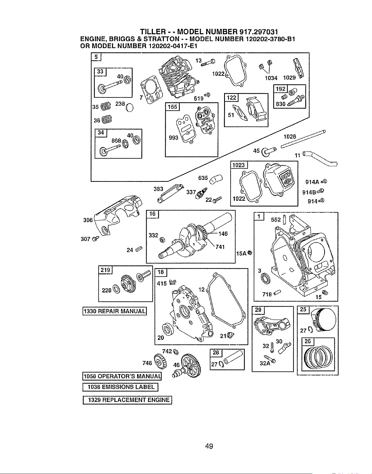
TILLER - - MODEL NUMBER 917.297031
ENGINE, BRIGGS & STRA'I-I'ON - . MODEL NUMBER 120202-3780-B1
OR MODEL NUMBER 120202-0417-E1
307
24 O
11330 REPAIR MANUAL t
552 0
718 O
I 1329 REPLACEMENT ENGINEt
49
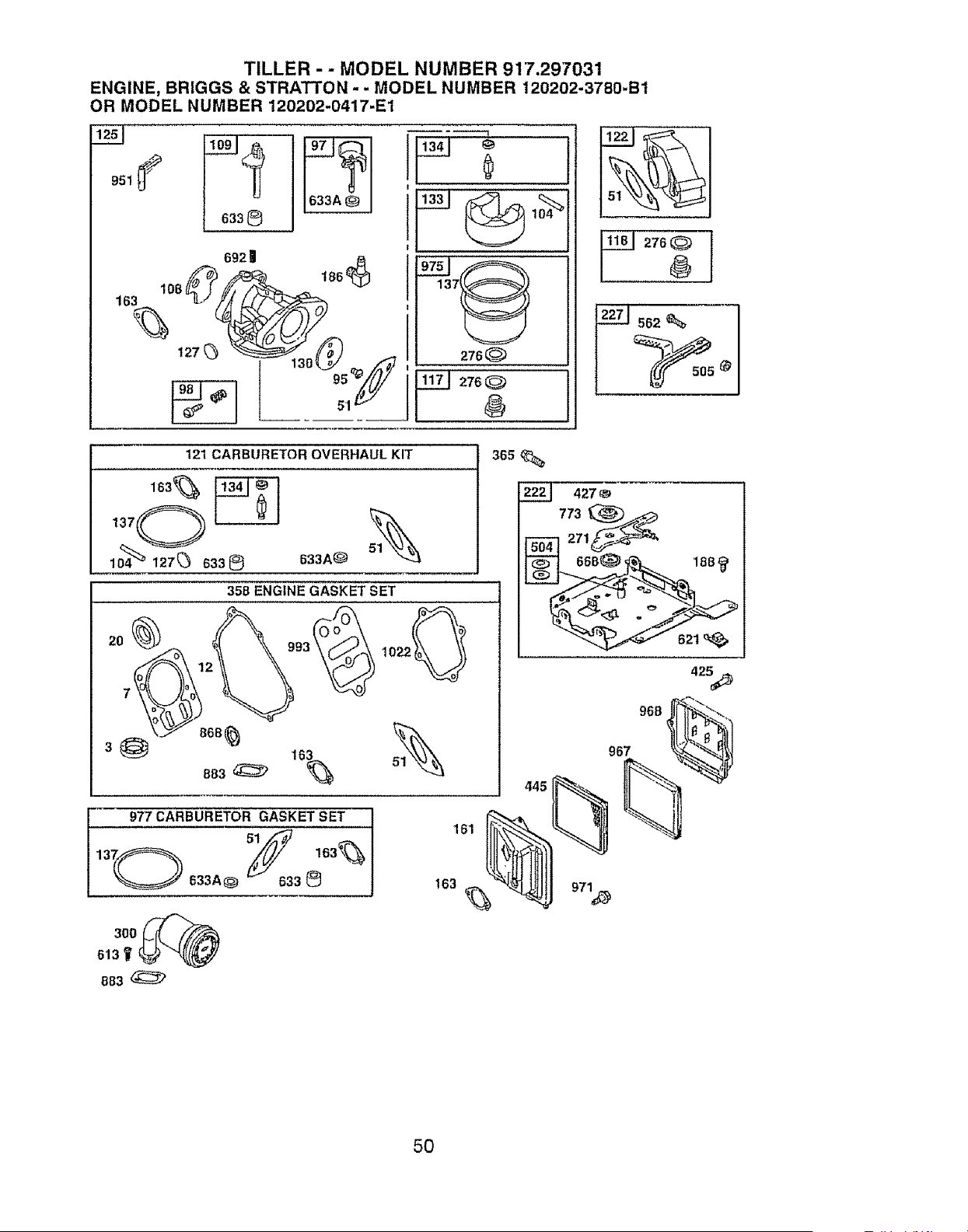
TILLER - - MODEL NUMBER 91'7.297031
ENGINE, BRIGGS & STRATTON - - MODEL NUMBER 120202-3780-Bt
OR MODEL NUMBER 120202-0417-E1
t633®
692 | .
,°,,oo0_ °°_
I
_76@
_J276_
8
@
121 CARBURETOR OVERHAUL KIT
_O _
lo4 127_3633@
20
633A(_'
358 ENGINE GASKET SET
1022_o °
977 CARBURETOR GASKET SET
633A@ 3 (_
613__ "-_;#
883
s6s
427
773 _
FgSil2,1_
42_
968
51_ 967
445
161 __
5O
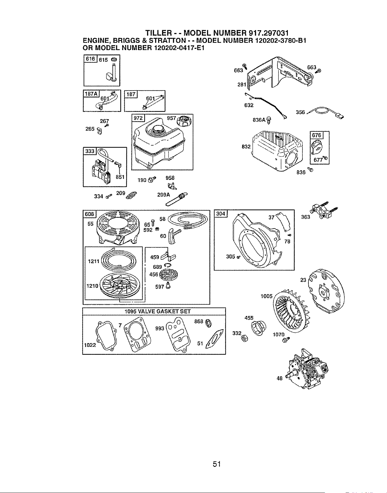
TILLER - - MODEL NUMBER 917.297031
ENGINE, BRIGGS & STRATTON - - MODEL NUMBER 120202-3780-B1
OR MODEL NUMBER 120202-0417-E1
615
267
265 _
!!!1 ,oo_,o,o
334 _ 209_> 209A ,_
592 ® 60
1095 VALVE GASKET SET
993 O o
10 51
836',e
51
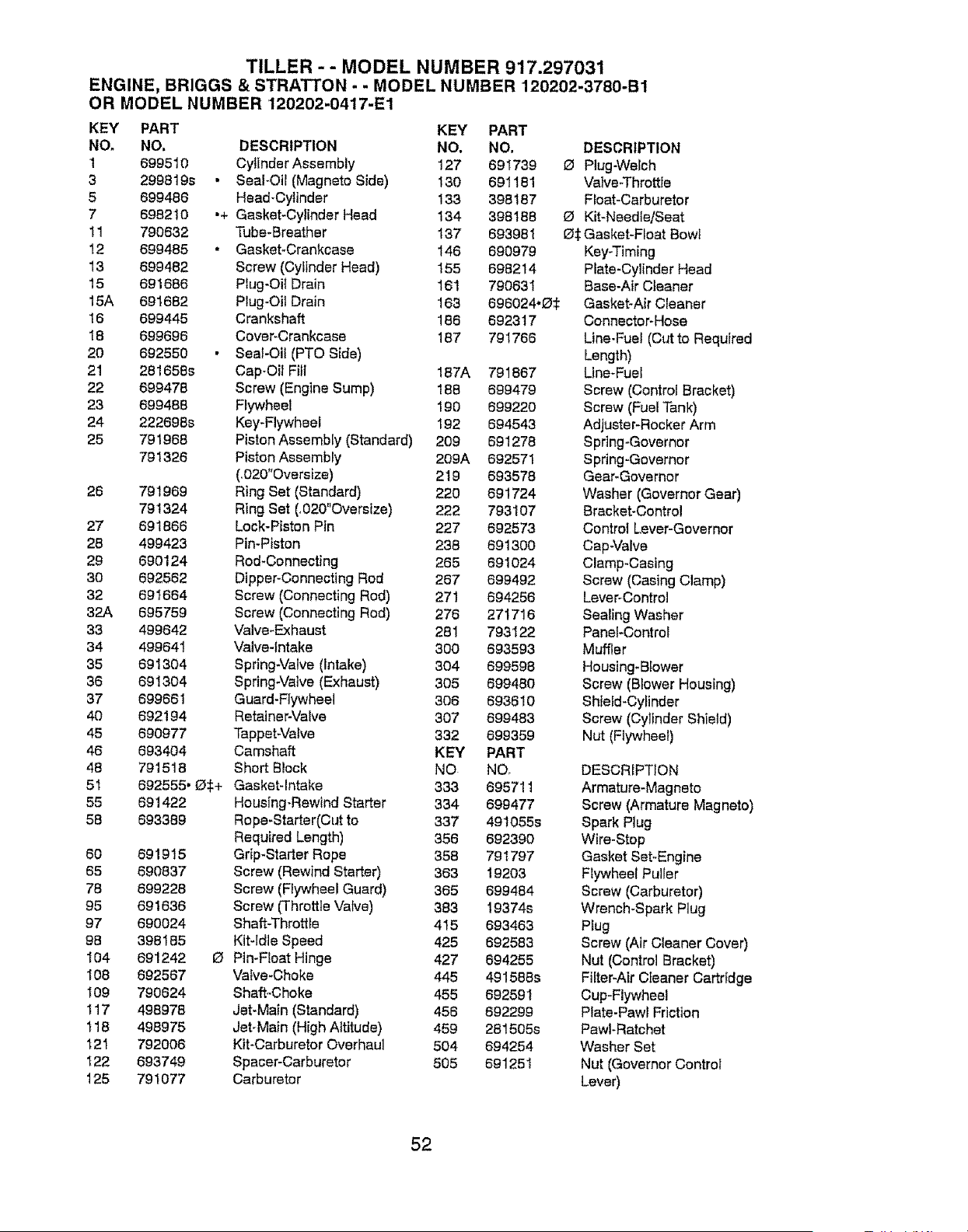
TILLER - - MODEL NUMBER 917.297031
ENGINE, BRIGGS & STRATTON - - MODEL NUMBER 120202-3780-B1
OR MODEL NUMBER 120202-0417-E1
KEY PART
NO. NO,
1 699510
3 299819s •
5 699486
7 698210 .+
11 790632
12 699485 •
13 699482
15 691886
15A 691682
16 699445
18 699696
20 692550 •
21 281658s
22 699478
23 699488
24 222698s
25 791968
791326
26 791969
791324
27 691866
28 499423
29 690124
3O 692562
32 691664
32A 695759
33 499642
34 499641
35 691304
36 691304
37 699681
40 692194
45 690977
46 693404
48 791516
51 692555. D$+
55 691422
58 693389
60 691915
65 690837
78 699228
95 691636
97 690024
98 398185
104 691242
108 692567
I09 790624
117 498978
118 498975
_21 792006
I22 693749
125 791077
O
KEY PART
DESCRIPTION NO. NO, DESCRIPTION
Cytinder Assembly 127 691739 GI Plug-Welch
SeaFOil (Magneto Side) 130 691181 Valve-Throttle
Head-Cylinder 133 398187 Float-Carburetor
Gasket-Cylinder Head 134 398188 O Kit-Needle/Seat
Tube-Breather 137 693981 Gf_:Gasket-Float Bowt
Gasket_Crankcase 146 690979 Key-Timing
Screw (Cylinder Head) 156 698214 Plate-Cylinder Head
Ptug-Oi{ Drain 16t 790831 Base-Air Cleaner
Plug*Oil Drain 163 696024,O_: Gasket-Air Cleaner
Crankshaft 186 6923 t 7 Connector-Hose
Cover-Crankcase 187 791766 Line-Fuel (Cut to Required
Sea!-Oil (PTO Side) Length)
Cap-Oil Fit1 187A 791667 Line*Fuel
Screw (Engine Sump) 188 699479 Screw (Control Bracket)
Flywheel 190 699220 Screw (Fuel Tank)
Key-Flywheet 192 694543 Adjuster-Rocker Arm
Piston Assembly (Standard) 209 691278 Spring-Governor
Piston Assembly 209A 692571 Spring-Governor
(_020"Oversize) 2t 9 693578 Gear-Governor
Ring Set (Standard) 220 691724 Washer (Governor Gear)
Ring Set (,020"Oversize) 222 793107 Bracket-Control
Lock-Piston Pin 227 692573 Control Lever-Governor
Pin-Piston 238 691300 Cap-Valve
Rod_Connecting 265 691024 Clamp_Casing
Dipper-Connecting Rod 267 699492 Screw (Casing Clamp)
Screw (Connecting Rod) 271 694256 Lever-Control
Screw (Connecting Rod) 276 271716 Sealing Washer
Valve-Exhaust 281 793122 Pane_-Control
Valve-Intake 300 693593 Muffler
Spring-Valve (Intake) 304 699598 Housing-Blower
Spring-Valve (Exhaust) 305 699480 Screw (Blower Housing)
Guard-Flywheel 306 693610 Shield-Cylinder
Retainer-Valve 307 699483 Screw (Cylinder Shield)
Tappet-Valve 332 699359 Nut (Flywheel)
Camshaft KEY PART
Short Block NO NO, DESCRIPTION
Gasket_lntake 333 695711 Armature-Magneto
Housing-Rewind Starter 334 699477 Screw (Armature Magneto)
Rope-Starter(Cut to 337 49t055s Spark Plug
Required Length) 356 692390 Wire-Stop
GHp*Starter Rope 358 791797 Gasket Set-Engine
Screw (Rewind Starter) 363 19203 FIywheel Puller
Screw (Flywheel Guard) 365 699484 Screw (Carburetor)
Screw ('Throttle Valve) 383 19374s Wrench-Spark Plug
Shaft-Throttle 4I 5 693463 Plug
Kit-Idle Speed 425 692583 Screw (Air Cleaner Cover)
Pin-Float Hinge 427 694255 Nut (Control Bracket)
Valve-Choke 445 491588s Filter-Air Cleaner Cartridge
Shaft-Choke 455 692591 Cup-Flywheel
Jet-Main (Standard) 456 692299 Plate-Pawl Fdction
Jet-Main (High Altitude) 459 281505s Pawl-Ratchet
Kit-Carburetor Overhau_ 504 694254 Washer Set
Spacer-Carburetor 505 691251 Nut (Governor Control
Carburetor Lever)
52
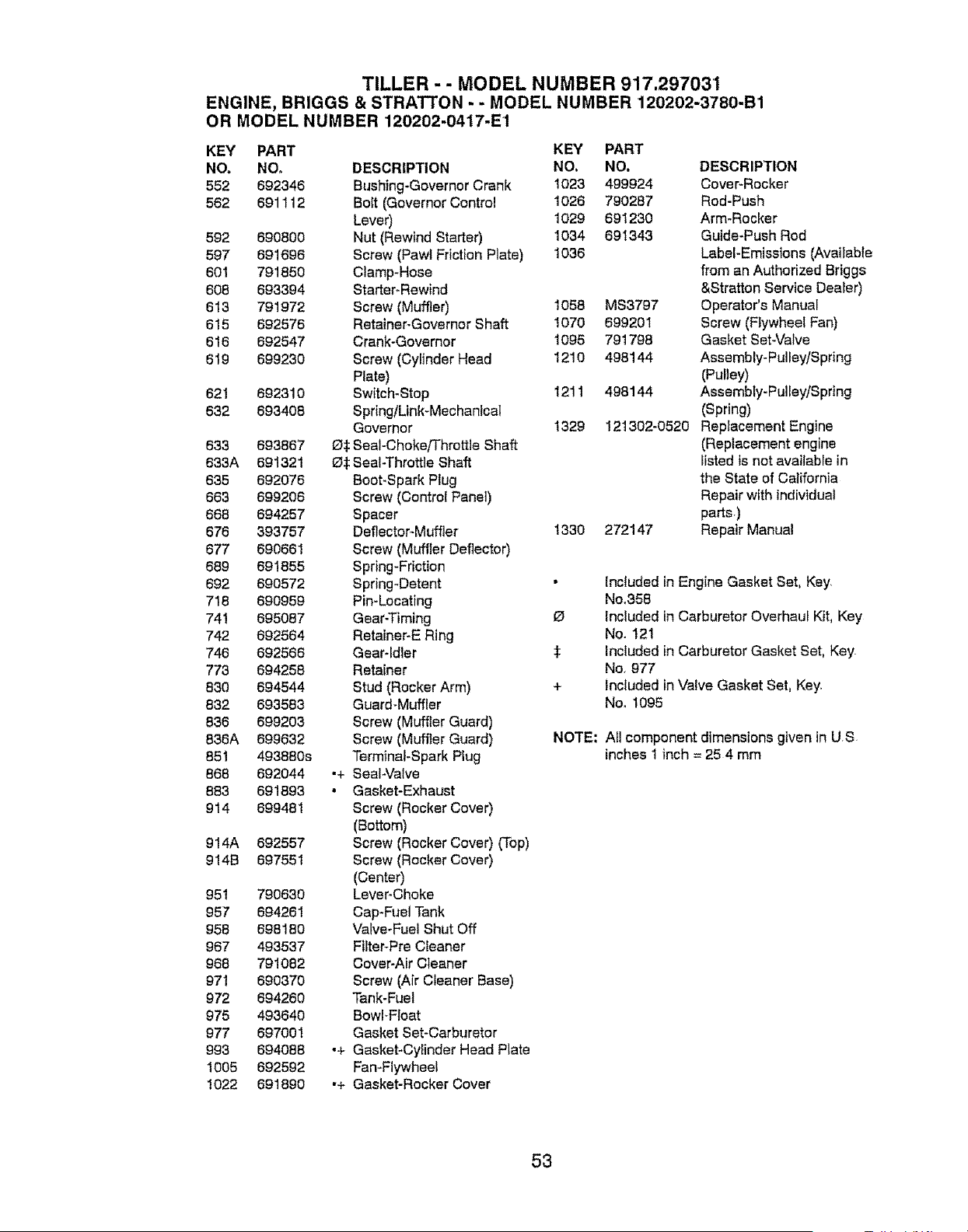
TILLER - - MODEL NUMBER 917.297031
ENGINE, BRIGGS & STRATTON - - MODEL NUMBER 120202-3780-B1
OR MODEL NUMBER 120202-0417-E1
KEY PART KEY
NO, NO, DESCRIPTION NO.
552 692346 Bushing-Governor Crank 1023
562 691112 Bolt (Governor Control 1026
Lever) 1029
592 690800 Nut (Rewind Starter) 1034
597 691696 Screw (Pawl Friction Plate) 1036
601 791850 Clamp-Hose
608 693394 Starter_Rewind
613 791972 Screw (Muffler) 1058
615 692576 Retainer-Governor Shaft 1070
616 692547 Crank-Governor 1095
619 699230 Screw (Cylinder Head 1210
Plate)
621 692310 Switch-Stop 1211
632 693408 Spring/Link-Mechanical
Governor 1329
633 693867 _ Seal-Choke/Throttle Shaft
633A 691321 _$ Seal-Throttle Shaft
635 692076 Boot-Spark Plug
663 699206 Screw (Control Panel)
668 694257 Spacer
676 393757 Deflector-Muffler 1330
677 690661 Screw (Muffler Deflector)
689 691855 Spring-Friction
692 690572 Spring-Detent
718 690959 Pin-Locating
741 695087 Gear-Timing
742 692564 Retainer-E Ring
746 692566 Gear-Idler $
773 694258 Retainer
830 694544 Stud (Rocker Arm) +
832 693583 Guard-Muffler
836 699203 Screw (Muffler Guard)
836A 699632 Screw (Muffler Guard) NOTE;
851 493880s Terminal-Spark Plug
868 692044 .+ Sea!-Valve
883 691893 • Gasket-Exhaust
914 699481 Screw (Rocker Cover)
(Bottom)
914A 692557 Screw (Rocker Cover) (Top)
914B 697551 Screw (Rocker Cover)
(Center)
951 790630 Lever_Choke
957 694261 Cap-Fuel Tank
958 698180 Valve-Fuel Shut Off
967 493537 Fitter-Pre Cleaner
968 791082 Cover-Air Cleaner
971 690370 Screw (Air Cleaner Base)
972 694280 Tank-Fuel
975 493640 BowFFloat
977 697001 Gasket Set-Carburetor
993 694088 ,+ Gasket-Cylinder Head Plate
1005 692592 Fan-Flywheel
1022 691890 ,+ Gasket-Rocker Cover
PART
NO. DESCRIPTION
499924 Cover-Rocker
790287 Rod-Push
691230 Arm-Rocker
691343 Guide-Push Rod
Label-Emissions (Available
from an Authorized Briggs
&Stratton Service Dealer)
MS3797 Operator's Manual
699201 Screw (F;ywheel Fan)
791798 Gasket Set-Valve
498144 Assembly- Pulley/Spring
(Pulley)
498144 Assembly-Pulley/Spring
(Spring)
121302-0520 Replacement Engine
(Replacement engine
listed is not available in
the State of California
Repair with individual
parts.)
272147 Repair Manual
Included in Engine Gasket Set, Key.
No,358
included in Carburetor Overhaul Kit, Key
No. 121
Included in Carburetor Gasket Set, Key
No, 977
Included in Valve Gasket Set, Key
No. 1095
All component dimensions given in US
inches1 inch = 254 mm
53

54

55

: } _:_;iii,;;¸:;! :,
_:/_i¸;i_
: :z; :_¸
i!i_'!,i!i_i_:i!
:- :7¸:;i
_:__'_i_:_i:i
!: i:,!,i:,;
:i:i_¸:¸,}¸;!,
• ;i ¸ :";:; :!_i: ¸•I:!! ! _i
• • ; i_ •_i ¸v •_: _
_ii_ii :; _: i, L_;i
Your Home
For repair - in your home - of all major brand appliances,
lawn and garden equipment, or heating and cooling systems,
no matter who made it, no matter who sold itl
For the replacement parts, accessories and
owner's manuals that you need to do-it-yourself.
For Sears professional installation of home appliances
and items like garage door openers and water heaters,
1-800-4-MY-HOME ® Anytime, day or night
(1-800-469-4663) (USA. and Canada)
v_.sears.com www.sears.ca
Our Home
For repair of carry-in products like vacuums, lawn equipment,
and electronics, call or go on-line for the nearest
Sears Parts and Repair Center,
1-800-488-1222 Anytime, day or night (U_SAo only)
v,wvw.sears.com
To purchase a protection agreement (U.S.A.)
or maintenance agreement (Canada) on a product serviced by Sears:
1-800-827-6655 (USA) 1-800-361-6665 (Canada)
:_ii_i__i:!i
: i i _¸_
_;_;i_"_il,'il
Para pedir servicio de reparaciSn
a domicilio, y para ordenar plazas:
1-888.SU-HOGAR sM
(1-888-7_427)
Au Canada pour service en francois: :
:t
1 800-LE FOYER Mc ......
(1-800-533-6937)
www sears ca
02410
© Sears,RoebuckandCo.
® Registered Trademark 1_MTrademark t s_ Service Mark of Sears, Roebuck and Co
® Marca Registrada / _MMarca de F&brica t sMMama de Servicio de Sears, Roebuck and Co
_c Marque de commerce / _ Marque d6pos_e de Sears, Roebuck and Co.
413807 03,23_07 CL Printed in U°S°A_