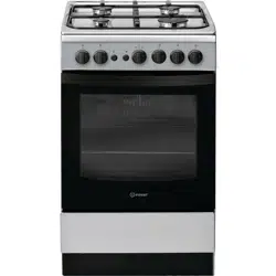
IS5G1PMSS/UKIS5G1PMSS/UKIS5G1PMSS/UK
EN
ENGLISH
3
Safety Instructions
Installation Guide
Daily Reference Guide 7
17
2
3
EN
SAFETYINSTRUCTIONS
IMPORTANTTOBEREADANDOBSERVED
Theseinstructionsarevalidifthecountry
symbolappearsontheappliance.Ifthesymbol
doesnotappearontheappliance,pleasereferto
thetechnicalinstructionswhichwillprovidethe
necessary instructions concerning modification of
theappliancetotheconditionsofuseofthe
country.
CAUTION:Useofthegascookingappliance
resultsintheproductionofheat,moistureand
productsofcombustionintheroominwhich
itisinstalled.Ensurethatthekitcheniswell
ventilated,especiallywhentheapplianceisin
use:keepnaturalventilationholesopenor
installamechanicalventilationdevice(mechanical
extractorhood).Prolongedintensiveuseofthe
appliance maycallforadditionalventilation,such
asopeningawindow,ormoreeffectiveventilation,
forexampleincreasingthelevelofmechanical
ventilation (if possible).
Failure to follow the information in this manual exactly maycause a
fire or explosion, resulting in property damage or personal injury.
Beforeusingtheappliance,readthesesafety
instructions.Keepthemnearbyforfuture
reference.
Theseinstructionsandtheapplianceitself provide
importantsafetywarnings,tobeobservedatall
times.Themanufacturerdeclinesanyliabilityfor
failuretoobservethesesafetyinstructions,for
inappropriateuseoftheapplianceorincorrect
setting of controls.
WARNING:If thehobsurfaceiscracked,donot
use the appliance – risk of electric shock.
WARNING:Danger offire:Donotstoreitems
on the cooking surfaces.
CAUTION:Thecookingprocesshastobe
supervised.Ashortcookingprocesshastobe
supervised continuously.
WARNING: Leavingthe hobunattendedwhen
cookingwithfatoroilcanbedangerous– riskof
fire.NEVERtrytoextinguishafirewithwater,but
switchoffthe applianceand thencoverthe flames
e.g. with a lid or a fire blanket.
Donotusethehobasaworksurfaceorsupport.
Keepclothesorotherflammablematerialsaway
from the appliance, until all the components have
cooled down completely – risk of fire.
Very young children (0-3years) shouldbe kept
awayfromtheappliance.Youngchildren(3-8
years)shouldbekeptawayfromtheappliance
unlesscontinuouslysupervised.Childrenfrom8
yearsoldandaboveandpersonswithreduced
physical,sensoryormentalcapabilitiesorlackof
experience and knowledge can usethis appliance
onlyiftheyaresupervisedorhavebeengiven
instructionsonsafeuseandunderstandthe
hazards involved.Children must notplay with the
appliance.Cleaningandusermaintenancemust
notbecarriedoutbychildrenwithoutsupervision.
CAUTION :In case ofhotplate glass breakage:-
shut immediately off all burners and any electrical
heatingelementandisolatetheappliancefrom
thepowersupply;-donottouchtheappliance
surface; -do not use the appliance
The glass lid can break in if it is heated up.
Turn off all the burners and the electric
plates before closing the lid. Do not shut
down lid when burner alight
WARNING:Theapplianceanditsaccessible
partsbecomehotduringuse. Careshouldbetaken
to avoidtouching heating elements.Children less
than8yearsofagemustbekeptawayunless
continuously supervised
Neverleavetheapplianceunattendedduring
use.Iftheapplianceissuitableforprobeusage,
onlyuseatemperatureproberecommendedfor
this oven - risk of fire.
Keepclothesorotherflammablematerials
awayfrom theappliance, untilall thecomponents
have cooled down completely - risk of fire.Always
bevigilantwhencookingfoodsrichinfat,oilor
when adding alcoholic beverages - risk of fire. Use
ovenglovestoremovepansandaccessories.At
theendofcooking,openthedoorwithcaution,
allowinghotairorsteamtoescapegradually
beforeaccessingthecavity-riskofburns.Donot
obstructhot airvents at thefront of theoven - risk
of fire.
Exercisecautionwhentheovendoorisinthe
open or down position, to avoid hitting the door.
Whenyouplacetherackinside,makesurethat
thestopis directedupwardsandinthebackofthe
cavity.
Thedeviceshallnotbeoperatedformore15s.If
after 15s the burner has not lit,stop operating the
deviceandopenthecompartmentdoorand/or
waitatleast1minbeforeattemptingafurther
ignition of the burner.
PERMITTEDUSE
CAUTION:Theapplianceisnotintendedto
beoperatedbymeansofanexternalswitching
device,suchasatimer,orseparateremote
controlled system.
Thisapplianceisintendedtobeusedin
householdandsimilarapplicationssuchas:staff
kitchenareasinshops,officesandotherworking
environments;farmhouses;byclientsinhotels,
motels,bed&breakfastandotherresidential
environments.
Nootheruseispermitted(e.g. heatingrooms).
Thisapplianceisnotforprofessionaluse.Do
not use the appliance outdoors.
4
Donotstoreexplosiveorflammable
substances(e.g. gasoline oraerosol cans) inside or
near the appliance - risk of fire.
Usepotsandpanswithbottomsthesame
widthasthatoftheburnersorslightlylarger(see
specifictable).Makesurepotsonthegratesdo
not protrude beyond the edge of the hob.
Improperuse ofthe gridscan resultin damage
to the hob: do not position the grids upside down
or slide them across the hob.
Do not let the burner flame extend beyond the edge of the pan.
Donotuse:Castirongriddles,ollarstones,terracottapotsandpans.
Heatdiffuserssuchasmetalmesh,oranyothertypes.Twoburners
simultaneously for one receptacle (e.g. Fish kettle).
Should particular local conditions of the delivered gas make the ignition
ofburnerdifficult,itisadvisabletorepeattheoperationwiththeknob
turned to small flame setting.
Incaseofinstallationofahoodabovethecooktop,pleaserefertothe
hood instructions for the correct distance.
Theprotectiverubberfeetonthegridsrepresentachockinghazardfor
young children.After removingthegrids,please ensurethatallthe feet
are correctly fitted.
INSTALLATION
Theappliancemustbehandledandinstalled
bytwoormorepersons-riskofinjury.Use
protectiveglovestounpackandinstall-riskof
cuts.
Theelectricalandgasconnectionsmust
comply with local regulations.
Installation,includingwatersupply(ifany),
electrical connections andrepairs must becarried
outbyaqualifiedtechnician.Donotrepairor
replaceanypartoftheapplianceunlessspecifically
statedintheusermanual.Keepchildrenawayfrom
theinstallationsite.Afterunpackingtheappliance,
makesurethatithasnotbeendamagedduring
transport.Intheeventofproblems,contactthe
dealeroryournearestAftersalesService.Once
installed,packagingwaste(plastic,styrofoam
partsetc.)mustbestoredoutofreachof
children-riskofsuffocation.Theappliancemust
bedisconnectedfromthepowersupplybefore
anyinstallationoperation-riskofelectricshock.
Duringinstallation,makesuretheappliancedoes
notdamagethepowercable-riskoffireor electric
shock.Onlyactivatetheappliancewhenthe
installation has been completed.
WARNING:Modificationoftheapplianceand
itsmethodofinstallationareessentialinorderto
usetheappliancesafelyandcorrectlyinallthe
additional countries.
Usepressureregulatorssuitableforthegas
pressure indicated in the instructions.
Theroommustbeequippedwithanair
extractionsystemthatexpelsanycombustion
fumes.
Theroommustalsoallowproperaircirculation,
as air is needed for combustion to occur normally.
Theflowofairmustnotbelessthan2m³/hper
kW of installed power.
The aircirculation system maytake air directly
from the outside by means of a pipe with an inner
crosssectionof atleast100cm²; theopeningmust
not be susceptible to blockages.
The system canalso providethe airneeded for
combustionindirectly,i.e.fromadjacentrooms
fittedwithaircirculationtubesasdescribedabove.
However,theseroomsmustnotbecommunal
rooms,bedroomsor roomsthat maypresent afire
hazard.
Liquidpetroleumgassinkstothefloorasit
isheavierthanair.Therefore,roomscontaining
LPGcylindersmustalsobeequippedwithvents
toallowgastoescapeintheeventofaleak.
ThismeansLPGcylinders,whetherpartiallyor
completelyfull,mustnotbeinstalledorstored
inroomsorstorageareasthatarebelowground
level(cellars,etc.).Itisadvisabletokeeponlythe
cylinderbeingusedintheroom,positionedso
thatit isnotsubject toheatproducedby external
sources(ovens,fireplaces,stoves,etc.)which
couldraise thetemperature ofthecylinder above
50°C.
Shouldyoufinditdifficulttoturntheknobsfortheburner,please
contacttheAfter-salesService,whocanreplaceoftheburnertapif
found to be faulty.
Theopeningsusefortheventilationanddispersionofheatmustnever
be covered.
Donotremovetheappliancefromits
polystyrenefoambaseuntilthetimeof
installation.
Connection with rigid pipe (copper or steel).
Ifthegaspressureisdifferentfromthe
recommendedpressure,asuitablepressure
regulatormustbefittedtotheinletpipein
accordancewiththecurrentNationalRegulations.
Donotinstalltheappliancebehindadecorative
door - risk of fire.
if the range is placed on a base, it must
be leveled and fixed to the wall by the
retention chain provided, to prevent the
appliance slipping from the base.
WARNING: In order to prevent the
appliance from tipping, the retention chain
must be installed. Refer to the instructions
for installation.
GASCONNECTION
WARNING:Priortoinstallation, ensurethatthe
localdistributionconditions(typeofgasandgas
pressure)andtheconfigurationoftheappliance
are compatible.
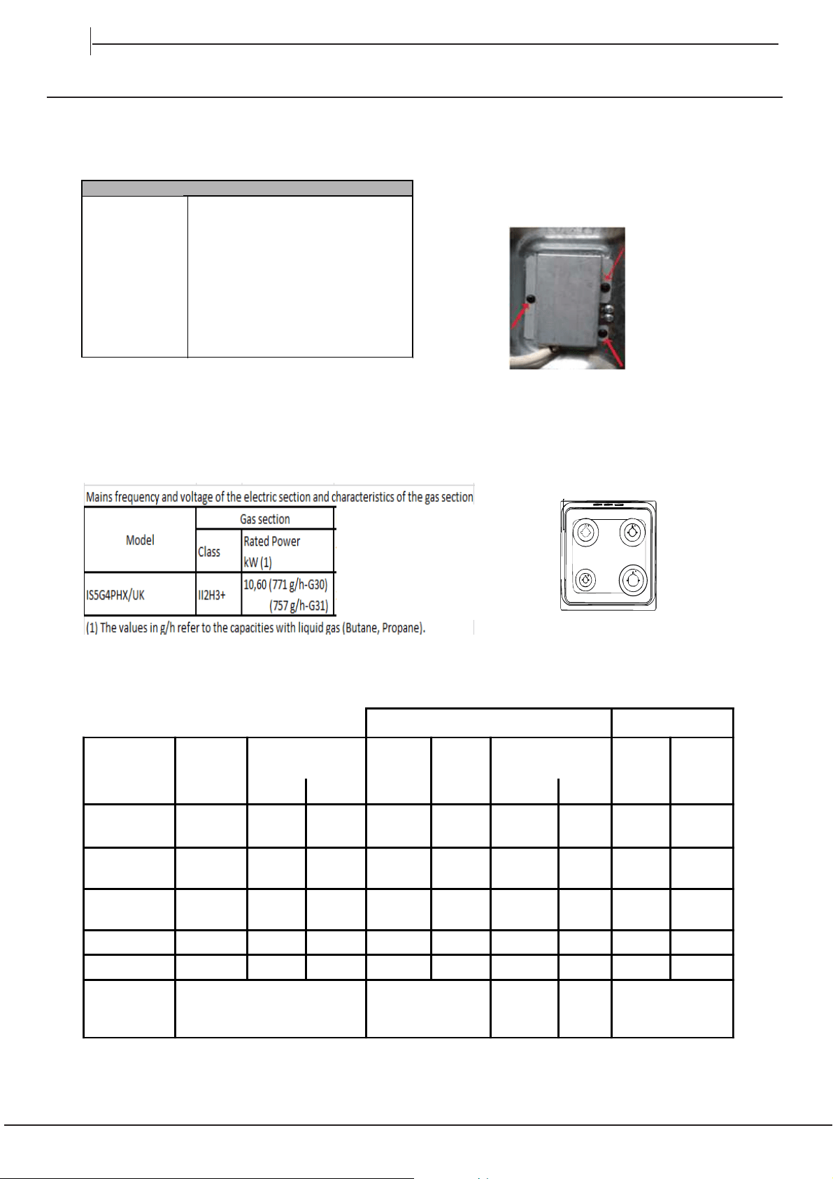
Checkthatthepressureofthegassupplyis
consistentwiththevaluesindicatedinTable1
(“Burner and nozzle specifications”).
WARNING:Theconfigurationconditionsof
thisappliancearestatedonthelabel(ordata
plate).
WARNING:Thisapplianceisnotconnected
toacombustionproductsevacuationdevice.It
5
mustbeinstalledandconnectedinaccordance
withcurrentinstallationregulations.Particular
attentionmustbepaidtotherelevant
requirementsregarding ventilation.
Iftheapplianceisconnectedtoliquidgas,
the regulation screwmust be fastnedas tightlyas
possible.
IMPORTANT:Whenthegascylinderorgas
containerisinstalled,itmustbeproperlysettled
(vertical orientation).
WARNING:Thisoperationmustbeperfomed
by a qualifiedtechnician
Useonlyflexibleorrigidmetalhoseforgas
connection.
Connection with a rigid pipe(copper or steel)
Connectiontothegassystemmustbecarried
outinsuchawayasnottoplaceanystrainof
anykindontheappliance.Thereisanadjustable
L-shapedpipefittingontheappliancesupply
rampandthisisfittedwithasealinorderto
preventleaks.Thesealmustalwaysbereplaced
afterrotating thepipefitting(the sealisprovided
withtheappliance).Thegassupplypipefittingis
a threaded 1/2 gas cylindrical male attachment.
Connectingaflexiblejointlessstainlesssteel
pipe to a threaded attachment
Thegassupplypipefittingisathreaded1/2gas
cylindricalmaleattachment.Thesepipesmust
beinstalledsothattheyareneverlongerthan
2000mmwhenfullyextended.Onceconnection
hasbeenmade,makesurethattheflexiblemetal
pipedoesnottouchanymovingpartsandisnot
compressed.Onlyuse pipesand sealsthatcomply
with current national regulations.
IMPORTANT:Ifastainelesssteelhoseisused,
itmustbeinstalledsoasnottouchanymoving
partofthefurniture(e.g.drawer).Itmustpass
thorughanareawheretherearenoobstructions
andwhereitispossibletoinspectitacrossits
entire length.
Theapplianceshouldbeconnectedtothemain
gas supply or to agas cylinder in compliance with
thecurrentnationalregulations.Beforemaking
theconnection,makesurethattheapplianceis
compatiblewiththegassupplyyouwishtouse.
Ifitisnot,followtheinstructionsindicatedinthe
paragraph "Adapting to different types ofgas".
Afterconnectiontothegassupply,checkfor
knobsfrommax position1*tominimum position
2* to check flame stability.
Connectiontothegasnetworkorthegas
cylindermaybecarryoutusingaflexiblerubber
orsteelhose,inaccordancewithcurrentnational
legislation.
ADAPTINGTODIFFERENTTYPESOFGAS
(Thisoperationneedstobecarriedoutbya
qualified technician.)
Inorderto adapttheappliancetoatypeofgas
otherthan thetype forwhichit wasmanufactured
(indicatedontheratinglabel),followthededicated
steps providedafter installation drawings.
ELECTRICALWARNINGS
IMPORTANT:Informationaboutcurrentand
voltageconsumptionisprovidedontherating
plate.
Theratingplateisonthefrontedgeofthe
oven (visible when the dooris open).
Itmustbepossibletodisconnecttheappliance
fromthepowersupplybyunpluggingitif
plugisaccessible,orbyamulti-poleswitch
installedupstreamofthesocketinaccordance
withthewiringrulesandtheappliancemust
beearthedinconformitywithnationalelectrical
safety standards.
Thepowercablemustbelongenoughtoconnecttheappliance,
oncefittedinitshousing,tothemainpowersupply.Donotpullthe
power supply cable.
Donotuseextensionleads,multiplesockets
oradapters.Theelectricalcomponentsmustnot
beaccessible totheuserafterinstallation.Donot
usetheappliancewhenyouarewetorbarefoot.
Donotoperatethisapplianceifithasadamaged
powercableorplug,ifitisnotworkingproperly,
or if it has been damaged or dropped.
Ifthesupplycordisdamaged,itmust
bereplacedwithanidenticalonebythe
manufacturer,itsserviceagentorsimilarly
qualifiedpersonsinordertoavoidahazard-
risk of electric shock.
Ifthepowercableneedstobereplaced,
contact an authorised service centre.
WARNING:Ensurethattheapplianceis
switchedoffbeforereplacingthelamptoavoid
the possibility of electric shock.
CLEANINGANDMAINTENANCE
WARNING:Ensurethattheapplianceis
switchedoffanddisconnectedfromthepower
supplybeforeperforminganymaintenance
operation;neverusesteamcleaningequipment-
risk of electric shock.
Donotuseharshabrasivecleanersormetal
scraperstocleanthedoorglasssincetheycan
scratch the surface, whichmay resultin shattering
of the glass.
Donotuseabrasiveorcorrosiveproducts,
chlorine-basedcleaners or panscourers.
Makesuretheappliancehascooleddown
before cleaning or performing maintenance.-risk
of burns.
WARNING:Switchofftheappliancebefore
replacing thelamp - risk of electric shock.
To avoiddamagingtheelectric ignitiondevice,donotuseitwhen
the burners are not in their housing.
Wearprotectiveglovesforcleaningand
maintenance.
leaks in accordance with current National
Regulations and Standards in force in the country
of installation. Light up the burners and turn the
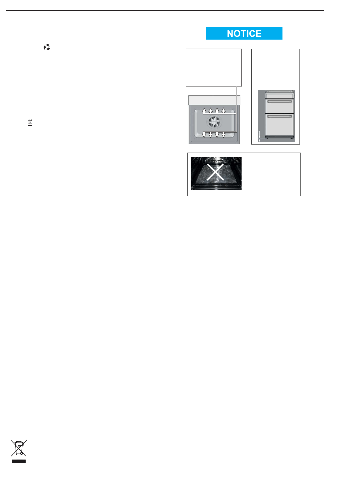
! ATTENTION
DURING INSTALLATION
THE FEET OF THE APPLIANCE
MUST BE LOWERED SO THAT
AN AIR GAP OF AT LEAST
10MM (1CM) IS LEFT BETWEEN
THE BASE OF THE APPLIANCE
AND THE FLOOR.
! VERY HOT SURFACES
YOU MUST KEEP THE OVEN
AND GRILL CAVITIES CLEAN
FOOD OR GREASE ON THESE
SURFACES COULD CAUSE
SMOKE AND POSSIBLY EVEN BURN
! ATTENTION
WHEN USING THE MAIN OVEN
YOU MUST ENSURE THAT THE
BASE OF THE CAVITY IS NOT
COVERED WITH ALUMINUM
FOIL, UTENSIL OR ANY OTHER
FORM OF COVERING. FAILURE
TO DO THIS MAY RESULT IN
THE CAVITY BEING DAMAGED.
10 mm
! ATTENTION! ATTENTION
! ATTENTION ! ATTENTION
! VERY HOT SURFACES! VERY HOT SURFACES
6
DISPOSALOFPACKAGINGMATERIALS
Thepackagingmaterial is100%recyclableandismarkedwiththe
recyclesymbol.Thevariouspartsofthepackagingmusttherefore
bedisposedofresponsiblyandinfullcompliancewithlocalauthority
regulationsgoverningwastedisposal.
DISPOSALOFHOUSEHOLDAPPLIANCES
Thisapplianceismanufacturedwithrecyclableorreusablematerials.
Disposeofitinaccordancewithlocalwastedisposalregulations.
Forfurtherinformationonthetreatment,recoveryandrecycling
ofhouseholdelectricalappliances, contactyourlocalauthority, the
collectionserviceforhouseholdwasteorthestorewhereyoupurchased
theappliance.ThisapplianceismarkedincompliancewithEuropean
Directive2012/19/EU,WasteElectricalandElectronicEquipment(WEEE).
Byensuringthisproductisdisposedofcorrectly,youwillhelpprevent
negativeconsequencesfortheenvironmentandhumanhealth.The
symbol
ontheproductorontheaccompanyingdocumentation
indicatesthatitshouldnotbetreatedasdomesticwastebutmustbe
takentoanappropriatecollectioncentrefortherecyclingofelectrical
andelectronicequipment.
ENERGYSAVINGTIPS
Onlypreheattheovenifspecifiedinthecookingtableoryourrecipe.Use
darklacqueredorenamelledbakingtraysastheyabsorbheatbetter.
Useapressurecookertosaveevenmoreenergyandtime.
DECLARATIONOFCONFORMITY
ThisappliancemeetsEcodesignrequirementsofEuropeanRegulation
66/2014incompliancewiththeEuropeanstandardEN60350-1.
ThisappliancemeetsEcodesignrequirementsofEuropeanRegulation
66/2014incompliancewiththeEuropeanstandardEN60350-2.
ThisappliancemeetsEcodesignrequirementsofEuropeanRegulation
66/2014incompliancewiththeEuropeanstandardEN30-2-1
ThisappliancemeetsEcodesignrequirementsofEuropeanRegulation
65/2014incompliancewiththeEuropeanstandardEN15181.
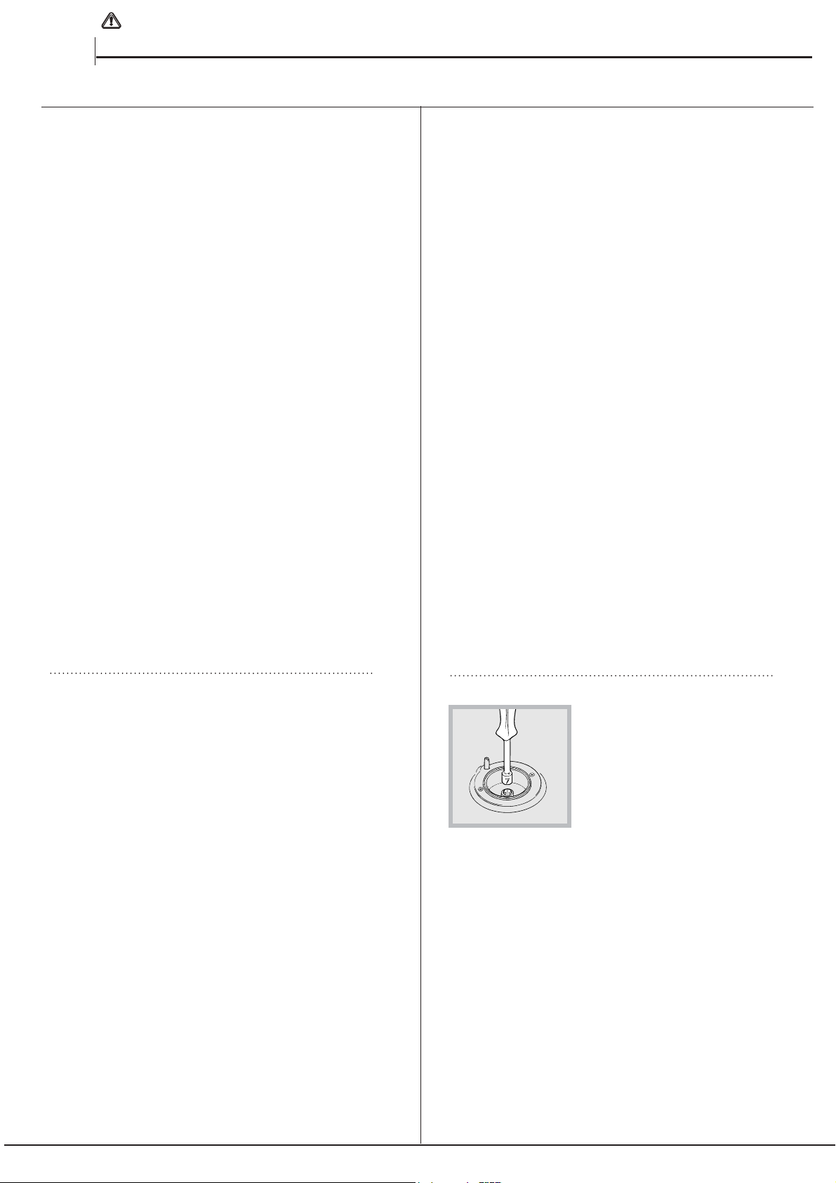
Timer Knob
Button for Oven
Light
IIgnition button
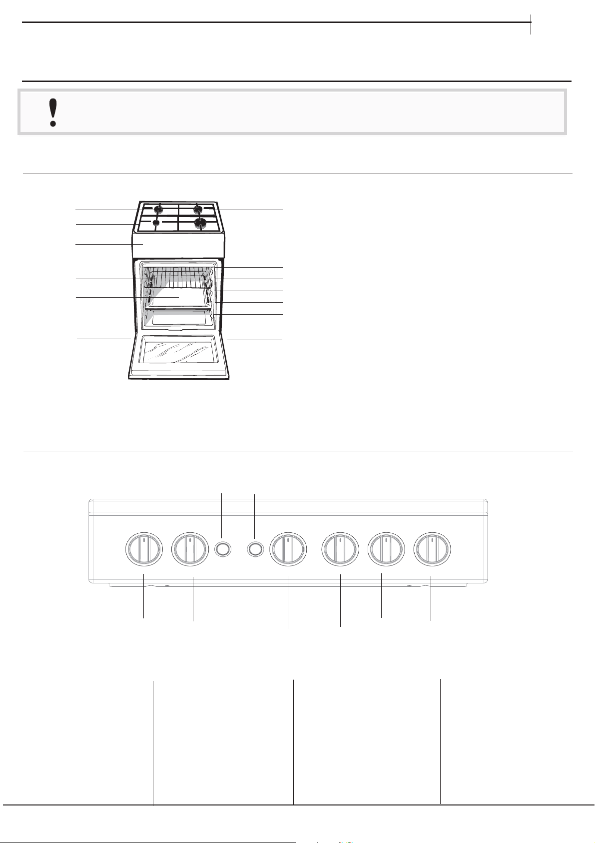
Hob grid
Control panel
GRILL
DRIPPING PAN
GUIDE RAILS
for the sliding racks
position 3
position 2
position 1
Gas burner
Containment surface
for spills
Adjustable foot
Adjustable
foot
position 5
position 4
Oven and Grill
Control Knob
Control Knobs for Gas
Burners on Hob
Control Knobs for Gas
Burners on Hob
I
7
EN
ENEN
Read the safety instructions carefully before using the product
EN
DAILY REFERENCE
GUIDE
DAILY REFERENCE
GUIDE
DAILY REFERENCE
GUIDE
DAILY REFERENCE
GUIDE
DAILY REFERENCE
GUIDE
DAILY REFERENCE
GUIDE
PRODUCT DESCRIPTION
1
2
1.
2.
3.
3
4
4.
5
5.
6
6.
7
8
9
10
11
7.
8.
9.
10.
11.
12
13
12.
13.
CONTROL PANEL
Control Knobs for Gas
Burners on Hob
Control Knobs for Gas
Burners on Hob
1
2
3
4
5
6
7
8
1.
2.
3.
4.
5.
6.
7.
8.
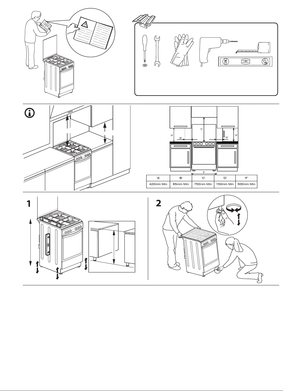
Positioning
This unit may be installed and used only in
permanently ventilated rooms according to the British
Standards Codes Of Practice: B.S. 6172/B.S. 5440,
Par. 2 and B.S. 6891 Current Editions. The following
requirements must be observed:
a. The cooker should not be installed in a bed sitting
room with a volume of less than 20m
3
. If it is installed
in a room of volume less than 5m
3
an air vent of
effective area of 100cm
2
is required, if it is installed
in a room of volume between 5m
3
and 10m
3
a
supplementary airvent area of 50cm2 is required,
if the volume exceeds 10m
3
no airvent is required.
However, if the room has a door or a window which
opens directly to the outside no air vent is required
even when the volume is between 5m
3
and 10m
3
.
b. During prolonged use of the appliance you may
consider it necessary to open a window to the
outside to improve ventilation.
This appliance must not be fitted on a platform.
The cooker is designed to fit between kitchen cabinets
spaced 500mm apart. The space either side need
only be sufficient to allow withdrawal of the cooker for
servicing. It can be used with cabinets one side or
both as well as in a corner setting. It can also be used
free-standing.
Adjacent side walls which project above hob level,
must not be nearer to the cooker than 150mm or 65mm
and should be protected by heat resistant
material. Any overhanging surface or cooker hood
should not be nearer than 750mm.
a. The cooker may be located in a kitchen, a kitchen/
diner or bed sitting room, but not in a bathroom or
shower room.
b. The hoods must be installed according to the
requirements in the hood handbook.
c. The wall in contact with the back of the cooker must
be of flameproof material.
d. The cooker is fitted with a safety chain that must be
attached to a hook, secured to the wall behind the
appliance.
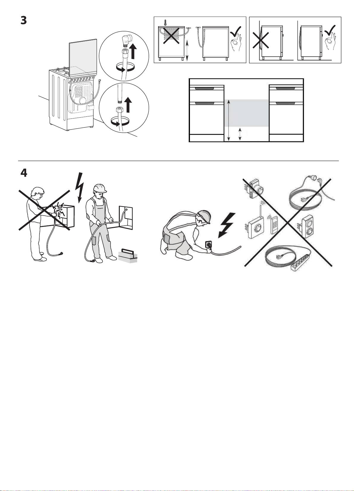
Gas connection
The cooker should be connected to the gas-supply
by a gas safe registered installer. During installation
of this product it is essential to fit an approved gas
tap to isolate the supply from the appliance for the
convenience of any subsequent removal or servicing.
The appliance must not be installed behind
a decorative door in order to avoid overheating
Connection of the appliance to the gas mains or liquid
gas must be carried out according to the prescribed
regulation in force, and only after it is ascertained that it
is adaptable to the type of gas to be used. If not, follow
the instructions indicated in the paragraph headed
“Adaptation to different gas types”. On some models
the gas supply can be connected on the left or on the
right, as necessary; to change the connection, reverse
the position of the hose holder with that of the cap
and replace the gasket (supplied with the appliance).
In the case of connection to liquid gas, by tank, use
pressure regulators that conform to the regulation in
force. The gas supply must be connected to the left
of the appliance. Be sure that the hose does not pass
through the rear of the cooker touching hot parts.
Make sure the supply pressure conforms
with the values shown in the table entitled
“Caracteristics of the burners and nozzles”.
When the cooker is installed between cabinets
(recessed), the gas connection must be effected
by an approved flexible hose with bayonet fitting
(BS 669 Current Edition). The gas inlet for the
cookers is a threaded G 1/2 gas female fitting.
EN
WARNING:Thisoperationmustbeperfomed
by a qualified technician
INSTALLATION TIPSINSTALLATION TIPSINSTALLATION TIPSINSTALLATION TIPSINSTALLATION TIPS
c. If there are other fuel burning appliances in the
same room, B.S.5440 Part 2 Current Edition, should,
be consulted to determine the requisite air vent.
The height of the cooker can be adjusted by means
of adjustable feet in the plinth (900mm - 915mm).
Adjust the feet by tilting the cooker from the side.
Then install the product into position.
8
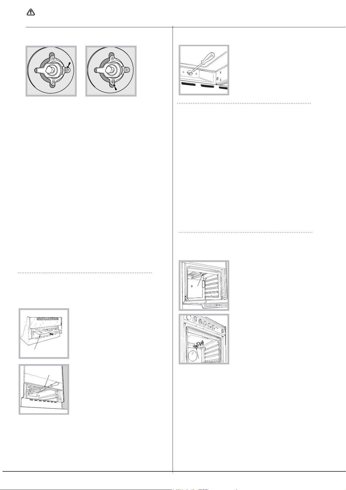
Adapting to different types of gas
It is possible to adapt the appliance to a type of gas other
than the default type (this is indicated on the rating label
on the cover).
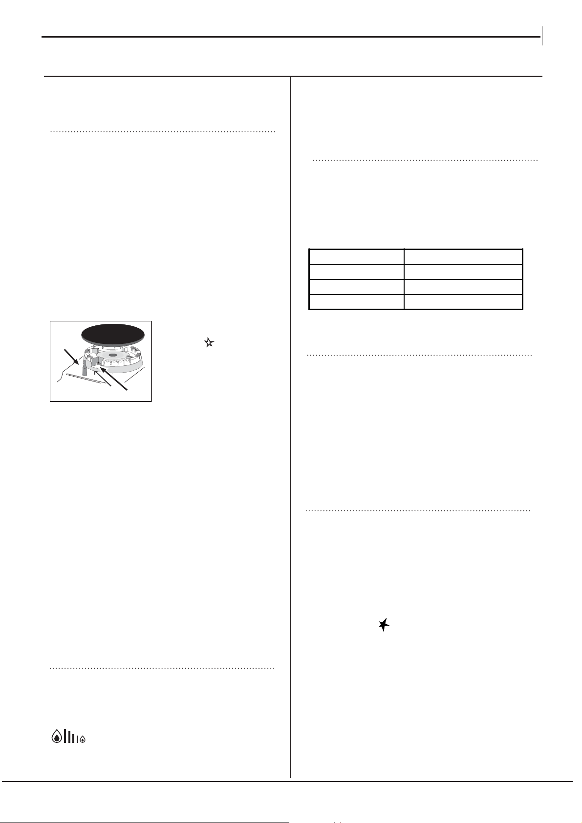
Adapting the hob
Replacing the nozzles for the hob
burners:
1. Remove the hob grids and
slide the burners off their seats.
2. Unscrew the nozzles using a 7
mm socket spanner ( see figure),
and replace them with nozzles
suited to the new type of gas(see Burner and nozzle
specifications table).
3. Replace all the components by following the above
instructions in reverse.
Adjusting the hob burners’ minimum setting:
1. Turn the tap to the minimum position.
2. Remove the knob and adjust the regulatory screw,
which is positioned inside or next to the tap pin, until the
flame is small but steady.
! If the appliance is connected to a liquid gas supply, the
bypass screw must be set to a minimum.
3. While the burner is alight, quickly change the position of the
knob from minimum to maximum and vice versa several times,
checking that the flame is not extinguished.
Upon completion of adjustment, reseal using sealing
wax or an equivalent material.
! The hob burners do not require primary air adjustment.
The room containing the appliance must contain
an openable window or an acceptable alternative
such as an adjustable louvre or hinged panel
opening direct to outside air.
! The hob burners do not require primary air adjustment.
! After adjusting the appliance so it may be used
with a different type of gas, replace the old rating
label with a new one that corresponds to the new
type of gas (these labels are available from
Authorised Technical Assistance Centres).
! Should the gas pressure used be different (or vary
slightly) from the recommended pressure, a suitable
pressure regulator must be fitted to the inlet hose in
accordance with current national regulations relating
to “regulators for channelled gas”.
Adapting the oven
Replacing the oven burner nozzle:
1. Remove the oven compartment.
2. Slide out the protection
panel A
(
see diagram
).
3. Remove the oven burner
after unscrewing the screws V
(
see figure
).
The whole operation will be
made easier if the oven door
is removed.
5. Turn the knob from the MAX position to the MIN
position quickly or open and shut the oven door,
making sure that the burner is not extinguished.
Adapting the grill
Replacing the grill burner nozzle:
1. Remove the oven burner
after loosening screw V (
see
figure
).
2. Unscrew the grill burner
nozzle using a special nozzle
socket spanner (
see figure
) or
preferably with a 7 mm socket
spanner, and replace it with a
new nozzle that is suited to the
new type of gas (
see Burner
and nozzle specifications table
).
! Be careful of the spark plug wires and the
thermocouple tubes.
! The oven and grill burners do not require primary
air adjustment.
! After adjusting the appliance so it may be used
with a different type of gas, replace the old rating
label with a new one that corresponds to the new
type of gas (these labels are available from
Authorised Technical Assistance Centres).
! Should the gas pressure used be different (or vary
slightly) from the recommended pressure, a suitable
pressure regulator must be fitted to the inlet hose in
accordance with current national regulations relating
to “regulators for channelled gas”.
A
V
V
I
WARNING:Thisoperationmustbeperfomed
by a qualified technician
9
4. Unscrew the nozzle using a
special nozzle socket spanner
(
see figure
) or with a 7 mm
socket spanner, and replace it
with a new nozzle that is
suited to the new type of gas
(
see Burner and nozzle
specifications table
).
Adjusting the gas oven burner’s minimum setting:
1. Light the burner (
see Start-up and Use
).
2. Turn the knob to the minimum position (MIN) after
it has been in the maximum position (MAX) for
approximately 10 minutes.
3. Remove the knob.
4. Tighten or loosen the adjustment screws on the
outside of the thermostat pin (
see figure
) until the
flame is small but steady.
! If the appliance is connected to liquid gas, the
bypass screw must be adjusted to minimum.
Upon completion of adjustment, reseal using sealing
wax or an equivalent material.
! After adjusting the appliance so it may be used with a
different type of gas, replace the old rating label with a
new one which corresponds to the new type of gas (these
labels are available from Authorised Technical Assistance
Centres).
! Should the gas pressure used be different (or vary
slightly) from the recommended pressure, a suitable
pressure regulator must be fitted to the inlet hose in
accordance with current standards EN 88-1 and EN
88-2 relating to “regulators for channelled gas”.
S
S
R
A
TECHNICAL DATA
Burners
may be adapted for use with any
type of gas shown on the data
plate, which is located inside the
flap or, after the oven
compartment has been opened,
on the left-hand wall inside the
oven.
Table of burner and nozzle specifications
Table 1 Liquid Gas Natural Gas
Burner Diameter
(mm)
Thermal Power
kW (p.c.s.*)
By-Pass
1/100
Nozzle
1/100
Flow*
g/h
Nozzle
1/100
Flow*
l/h
Nominal Reduced (mm) (mm) *** ** (mm)
Fast
(Large)(R)
100 3.00 0.7 41 87 218 214 128 286
Semi Fast
(Medium)(S)
75 1.90 0.4 30 69 138 136 104 181
Auxiliary
(Small)(A)
51 1.00 0.4 30 50 73 71 78 95
Oven - 2.80 1.0 46 80 204 200 119 267
Grill - 2.30 - - 75 167 164 114 219
Supply
Pressures
Nominal (mbar)
Minimum (mbar)
Ma ximum (mbar)
28-30
20
35
37
25
45
20
17
25
* At 15°C and 1013 mbar- dry gas
** Propane P.C.S. = 50,37 MJ/Kg
*** Butane P.C.S. = 49,47 MJ/Kg
Natural P.C.S. = 37,78 MJ/m
3
EN
TECHNICAL DATATECHNICAL DATATECHNICAL DATATECHNICAL DATATECHNICAL DATATECHNICAL DATA
10
After installing the power cable, screw the metal cover
with three screws.
Using the hob
Lighting the burners
For each BURNER knob there is a complete ring showing
the strength of the flame for the relevant burner.
To light one of the burners on the hob:
1. Press the BURNER knob and turn it in an
anticlockwise direction so that it is pointing to the
maximum flame setting (.
2. Adjust the intensity of the flame to the desired level
by turning the BURNER knob in an anticlockwise
direction. This may be the minimum setting &, the
maximum setting ( or any position in between the two.
If the appliance is fitted with an electronic lighting
device* ( see gure), press the
ignition button, marked with
the symbol
then hold the
BURNER knob down and
turn it in an anticlockwise
direction, towards the
maximum flame setting, until
the burner is lit.
Several models are equipped with an ignition device
which is built into the knob; in this case the electronic
ignition device* is present ( see gure) but the ignition
button is not. Simply press the BURNER knob and turn
it in an anticlockwise direction so that it is pointing
to the maximum flame setting, until the burner is lit.
The burner may be extinguished when the knob is
released. If this occurs, repeat the operation, holding
the knob down for a longer period of time.
! If the flame is accidentally extinguished, switch off the
burner and wait for at least 1 minute before attempting
to relight it.
If the appliance is equipped with a flame failure
safety device*, press and hold the BURNER knob for
approximately 2-3 seconds to keep the flame alight
and to activate the device.
To switch the burner off, turn the knob until it reaches
the stop position • .
Practical advice on using the burners
For the burners to work in the most efficient way
possible and to save on the amount of gas consumed,
it is recommended that only pans that have a lid and
a flat base are used. They should also be suited to the
size of the burner.
To identify the type of burner, please refer to the
diagrams contained in the “Burner and nozzle
specifications”.
Using the oven
! The first time you use your appliance, heat the empty
oven with its door closed at its maximum temperature
for at least half an hour. Ensure that the room is well
ventilated before switching the oven off and opening
the oven door. The appliance may emit a slightly
unpleasant odour caused by protective substances
used during the manufacturing process burning away.
! Never put objects directly on the bottom of the oven;
this will avoid the enamel coating being damaged.
Only use position 1 in the oven when cooking with the
rotisserie spit.
X
C
Burner Ĝ Cookware diameter (cm)
Fast (R) 24 - 26
Semi Fast (S) 16 - 20
Auxiliary (A) 10 - 14
Flame adjustment according to levels
the burner flame intensity can be adjusted with the
knob according to 6 power levels, from maximum
to minimum with 4 intermediate positions:
a click will indicate the change from one level to
another when turning the knob. The system
guarantees a more precise adjustment, allows
to replicate the flame intensity and to identify
easily the preferred level for different cooking
operations.
Flame adjustment according to levelsFlame adjustment according to levels
Lighting the oven
To light the oven burner, bring a flame or gas lighter
close to opening F (see figure) and press the OVEN
control knob while turning it in an anticlockwise
direction until it reaches the MAX position.
If the appliance is fitted with an electronic lighting
device* (see figure), press the ignition button, marked
with the symbol
, then hold the OVEN control knob
and turn it in an anticlockwise direction, towards the
MAX position, until the burner is lit. If, after 15 seconds,
the burner is still not alight, release the knob, open the
oven door and wait for at least 1 minute before trying to
light it again. If there is no electricity the burner may be
lit using a flame or a lighter, as described above.
11
EN
START-UP AND USESTART-UP AND USESTART-UP AND USESTART-UP AND USESTART-UP AND USESTART-UP AND USESTART-UP AND USE
* Only available in certain models.
Grill
To light the grill, press the OVEN control knob while
turning it in a clockwise direction until it reaches the
, position. The grill enables the surface of food
to be browned evenly and is particularly suitable for
roast dishes, schnitzel and sausages. Place the rack
in position 4 or 5 and the dripping pan in position 1 to
collect fat and prevent the formation of smoke.
! The grill is fitted with a safety device and it is
therefore necessary to hold the OVEN control knob
down for approximately 6 seconds.
! If the flame is accidentally extinguished, switch off the
burner and wait for at least 1 minute before attempting
to relight the grill.
! When using the grill, leave the oven door ajar,
positioning the deflector D between the door and the
control panel ( see gure ) in order to prevent the knobs
from overheating.
Oven light
The light may be switched on at any moment by
pressing the OVEN LIGHT
button.
Timer*
To activate the Timer proceed as follows:
1. Turn the TIMER knob in
a clockwise direction for
almost one complete revolution to set the buzzer.
2. Turn the TIMER knob in an anticlockwise direction
to set the desired length of time.
Lower compartment*
D
A
S
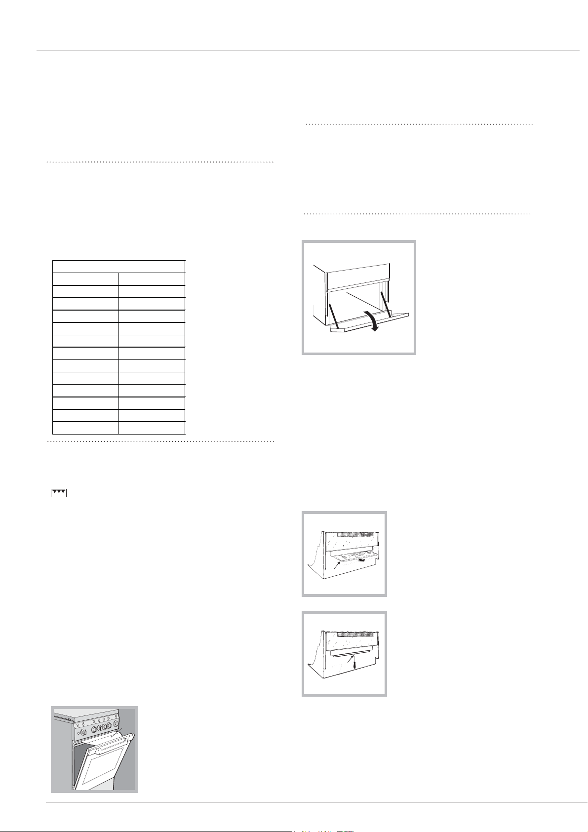
There is a compartment
underneath the oven
that may be used to
store oven accessories
or deep dishes. To open
the door pull it
downwards (
see
figure
).
! The internal surfaces of the compartment (where
present) may become hot.
! Do not place flammable materials in the lower oven
compartment.
In gas cooker models, there is a sliding protection
layer A that shields the lower compartment from the
heat generated by the burner (
see figure
).
To remove the sliding
protection remove the screw S
(
see figure
). To replace it, lock
it in place with the screw S.
! Before using the oven make
sure that the sliding protection
is fixed correctly.
Adjusting the temperature
To set the desired cooking temperature, turn the
OVEN control knob in an anticlockwise direction.
Temperatures are displayed on the control panel and
may vary between MIN (145°C) and MAX (240°C).
Once the set temperature has been reached, the oven
will keep it constant by using its thermostat.
Conventional Oven
Gas mark °C
MIN MIN
1 145
2 150
3 160
4 170
5 180
6 190
7 200
8 210
9 220
10 230
MAX 240
! The oven is fitted with a safety device and it is
therefore necessary to hold the OVEN control knob
down for approximately 6 seconds.
! If the flame is accidentally extinguished, switch off the
burner and wait for at least 1 minute before attempting
to relight the oven.
12

Food to be cooked
Wt.
(Kg)
Cooking position of
shelves from bottom
Temperature
(°C)
Pre-heating time (min)
Cooking time
(min.)
Pasta
Lasagne
Cannelloni
Pasta bakes au gratin
2.5
2.5
2.5
2
2
2
200-210
200
200
10
10
10
75-85
50-60
50-60
Meat
Veal
Chicken
Duck
Rabbit
Pork
Lamb
1.5
1.5
1.8
2.0
2.1
1.8
3
3
3
3
3
3
200-210
210-220
200
200
200
200
10
10
10
10
10
10
95-100
90-100
100-110
70-80
70-80
100-105
Fis h
Mackerel
Dentex
Trout baked in paper
1.1
1.5
1.0
3
3
3
180-200
180-200
180-200
10
10
10
45-50
45-55
45-50
Pizza
Napolitan 1.0 4 210-220 15 20-25
Cake
Biscuits
Tarts
Savoury pie
Raised Cakes
0.5
1.1
1.0
1.0
4
4
4
4
180
180
180
170
15
15
15
15
25-35
40-45
50-55
40-45
Grill cooking
Veal steaks
Cutlets
Hamburgers
Mackerels
Toast sandwiches
1
1,5
1
1
n.° 4
4
4
3
4
4
5
5
5
5
5
15-20
20
20-30
15-20
4-5
NB: cooking times are approximate and may vary according to personal taste. When cooking using the grill, the drip ping- pan must
always be placed on the 1st oven rack from the bottom.
WARNING! The oven is
provided with a stop sys-
tem to extract the racks
and prevent them from
coming out of the oven.(1)
As shown in the drawing,
to extract them comple-
tely, simply lift the racks,
holding them on the front
part, and pull (2).
13
EN
OVEN COOKING ADVICE TABLEOVEN COOKING ADVICE TABLEOVEN COOKING ADVICE TABLEOVEN COOKING ADVICE TABLE
OVEN COOKING ADVICE TABLE
Switching the appliance off
Disconnect your appliance from the electricity supply
before carrying out any work on it.
Inspecting the oven seals
Check the door seals around the oven periodically. If
the seals are damaged, please contact your nearest
Authorised After-sales Service Centre. We recommend
that the oven is not used until the seals have been
replaced.
Gas tap maintenance
Over time, the taps may become jammed or difficult to
turn. If this occurs, the tap must be replaced.
! This procedure must be performed by a qualified
technician who has been authorised by the
manufacturer.
Replacing the oven light bulb
1. After disconnecting the oven
from the electricity mains, remove
the glass lid covering the lamp
socket ( see figure).
2. Remove the light bulb and
replace it with a similar one:
voltage 230 V, wattage 25 W,
cap E 14.
3. Replace the lid and reconnect the oven to the electricity
supply.
! Do not use the oven lamp as/for ambient lighting.
Assistance
Please have the following information handy:
• The appliance model (Mod.).
• The serial number (S/N).
This information can be found on the data plate located
on the appliance and/or on the packaging.
• Cook your food in closed pots or pans with well-fitting
lids and use as little water as possible. Cooking with
the lid off will greatly increase energy consumption
• Use purely flat pots and pans
• If you are cooking something that takes a long time,
it's worth using a pressure cooker, which is twice as
fast and saves a third of the energy.
Respecting and conserving the environment
• Whenever possible, avoid pre-heating the oven
and always try to fill it. Open the oven door as little
as possible because heat is lost every time it is
opened. To save a substantial amount of energy,
simply switch off the oven 5 to 10 minutes before the
end of your planned cooking time and use the heat
the oven continues to generate.
• Keep gaskets clean and tidy to prevent any door
energy losses
• If you have a timed tariff electricity contract, the “delay
cooking” option will make it easier to save money by
moving operation to cheaper time periods.
• The base of your pot or pan should cover the hot plate.
If it is smaller, precious energy will be wasted and
pots that boil over leave encrusted remains that can
be difficult to remove.
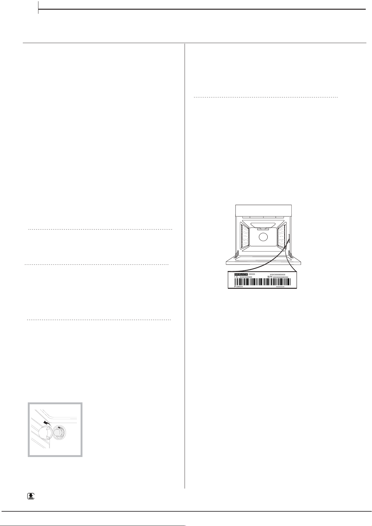
AFTER-SALES SERVICE
To receive assistance, call the number given on the
warranty leaflet enclosed with the product or follow
the instructions on our website. Be prepared to
provide:
•
a brief description of the problem;
•
the exact model type of your product;
•
the assistance code (the number following the word
SERVICE on the identification plate attached to the
product, which can be seen on the inside edge when
the oven door is open);
•
your full address;
•
a contact telephone number.
Please note: If repairs are required, contact an
authorised service centre that is guaranteed to use
original spare parts and perform repairs correctly.
Please refer to the enclosed warranty leaflet for more
information on the warranty.
WWW
A complete product specification, including the energy efficiency ratings for this oven, can be read and
downloaded from our website
www.indesit.com
EN
MAINTENANCE AND
CLEANING
MAINTENANCE AND
CLEANING
MAINTENANCE AND
CLEANING
MAINTENANCE AND
CLEANING
MAINTENANCE AND
CLEANING
MAINTENANCE AND
CLEANING
14
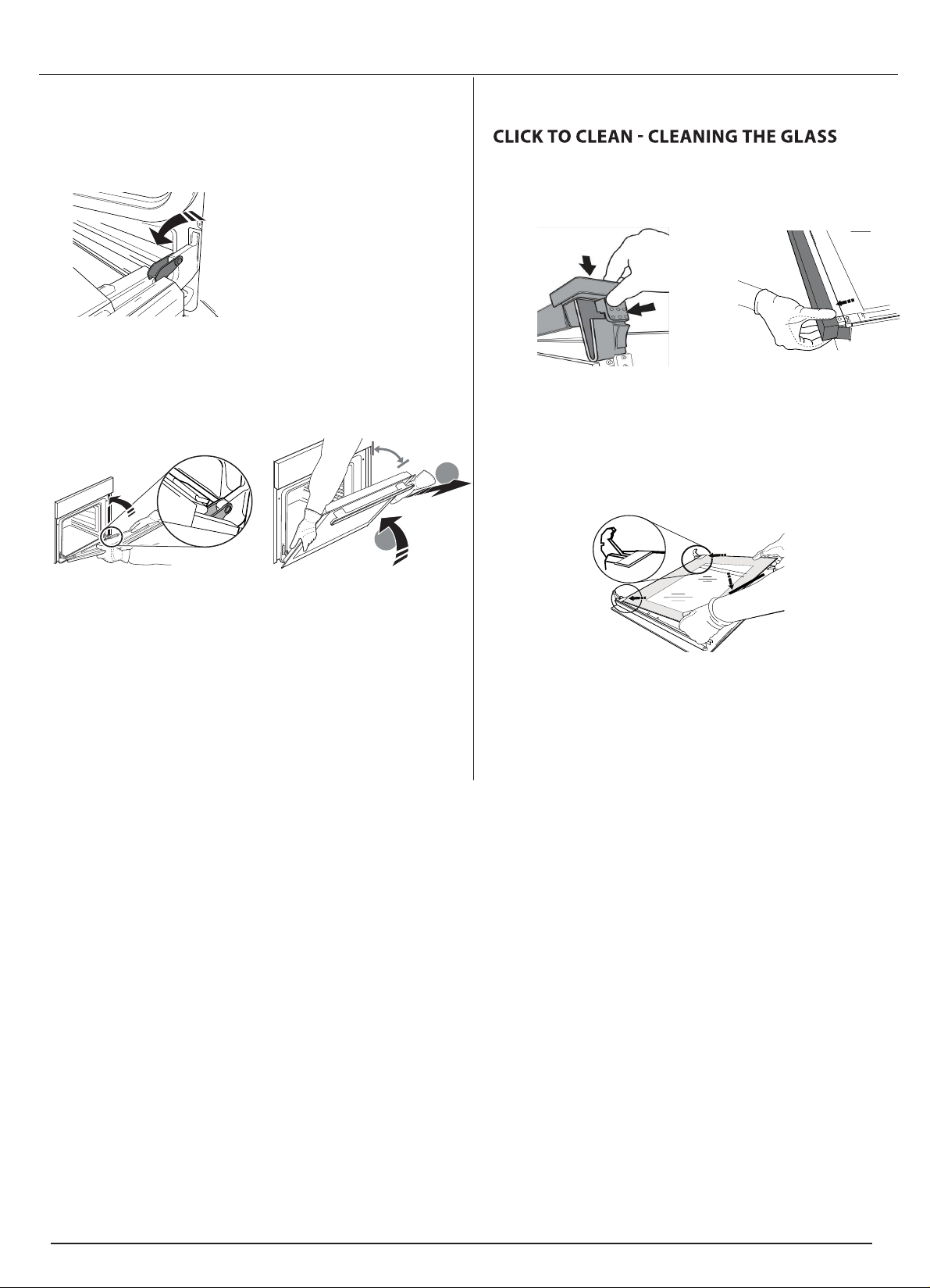
REMOVING AND REFITTING THE DOOR
1.
To remove the door, open it fully and lower the
catches until they are in the unlock position.
2.
Close the door as much as you can.
Take a firm hold of the door with both hands – do not
hold it by the handle.
Simply remove the door by continuing to close it
while pulling it upwards (a) at the same time until it is
released from its seating (b).
~60°
a
b
~15°
Put the door to one side, resting it on a soft surface.
3.
Refit the door by moving it towards the oven,
aligning the hooks of the hinges with their seating
and securing the upper part onto its seating.
4.
Lower the door and then open it fully.
Lower the catches into their original position: Make
sure that you lower them down completely.
5.
Try closing the door and check to make sure that it
lines up with the control panel. If it does not, repeat
the steps above.
1.
After removing the door and resting it on a soft
surface with the handle downwards, simultaneously
press the two retaining clips and remove the upper
edge of the door by pulling it towards you.
2.
Lift and firmly hold the inner glass with both
hands, remove it and place it on a soft surface before
cleaning it.
3.
4.
Refit the upper edge: a click will indicate correct
positioning. Make sure the seal is secure before
refitting the door.
When reassembling the inner door glass
insert the glass panel correctly so that the
text written on the panel is not reversed
and can be easily legible.
15
Product Guarantee and Repair
Information
Please note, our advisors will require the following information:
Model number:
Serial number:
Guarantee
12 Months Parts and Labour Guarantee
Your appliance has benefit of our manufacturer’s guarantee, which covers
t
he cost of breakdown repairs for twelve months from the date of purchase.
This gives you the reassurance that if, within that time, your appliance is proven
to be defective because of either workmanship or materials, we will, at our
discretion, either repair or replace the appliance at no cost to you:
This guarantee is subject to the following conditions:
- The appliance has been installed and operated correctly and in accordance
with our operating and maintenance instructions.
- The appliance is used only on the electricity or gas supply printed on the
rating plate.
-
The appliance has been used for normal domestic purposes only.
- The appliance has not been altered, serviced, maintained, dismantled, or
otherwise interfered with by any person not authorised by us.
- Any repair work must be undertaken by us or our appointed agent.
- Any parts removed during repair work or any appliance that is replaced
become our property.
- The appliance is used in the United Kingdom or Republic of Ireland.
The guarantee does not cover:
- Damage resulting from transportation, improper use, neglect or interference
or as a result of improper installation.
- Replacement of any consumable item or accessory. These include but
are not limited to:plugs,cables,batteries,light bulbs,fluorescent tubes and
starters, covers and filters.
- Replacement of any removable parts made of glass or plastic.
THIS
GUARANTEE WILL NOT APPLY IF THE APPLIANCE HAS BEEN
USED IN COMMERCIAL OR NON-DOMESTIC PREMISES.
Recycling and Disposal Information
As part of Hotpoint’s continued commitment to helping the environment,
Hotpoint reserves the right to use quality, recycled components to keep down
customer costs and minimise material wastage.
Please dispose of packaging and old appliances carefully. To minimise the
risk of injury to children, remove the door, plug, and cut the mains cable off
flush with the appliance.Dispose of these parts separately to ensure that th
e
appliance can no longer be plugged into mains socket, and the door cannot
be locked shut.
Repairs and After Sales
For product help and advice, repairs, spare parts or accessories, we’re here
to help.
For local repair engineers -
03448 111 606
ROI - 0818 313 413
UK standard local rate applies
ROI local Irish rate applies
For Parts and Accessories visit:
parts.hotpoint.co.uk/shop
Please remember to register your appliance at www.hotpointservice.co.uk
to activate your 10 year parts guarantee.
16
17mm - 0,67inch
Min. 420 mm
Min. 750 mm
max. 15 mm
17
>50°C
Gas hose connection point must be installed within the shaded area
Connecting to gas supply
600
300
600
-----------
------------
18

19

20
11/2018
XEROX FABRIANO
www.indesit.com
Whirlpool EMEA S.p.A.
Via Carlo Pisacane n.1
20016 Pero (MI), Italy
VAT number: IT00693740425
W11309149