Read the safety instructions carefully before using the product
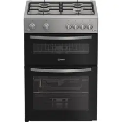
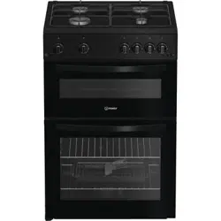
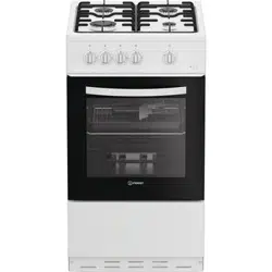
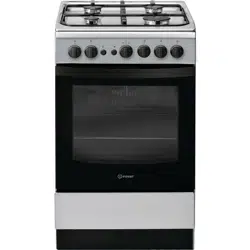
PRODUCT DESCRIPTION
Gas burner
Hob grid
Containment surface for spills
Control panel
GRILL
DRIPPING PAN GUIDE RAILS for the sliding racks
position 5
position 4
position 3
position 2
position 1
Adjustable foot
Adjustable foot
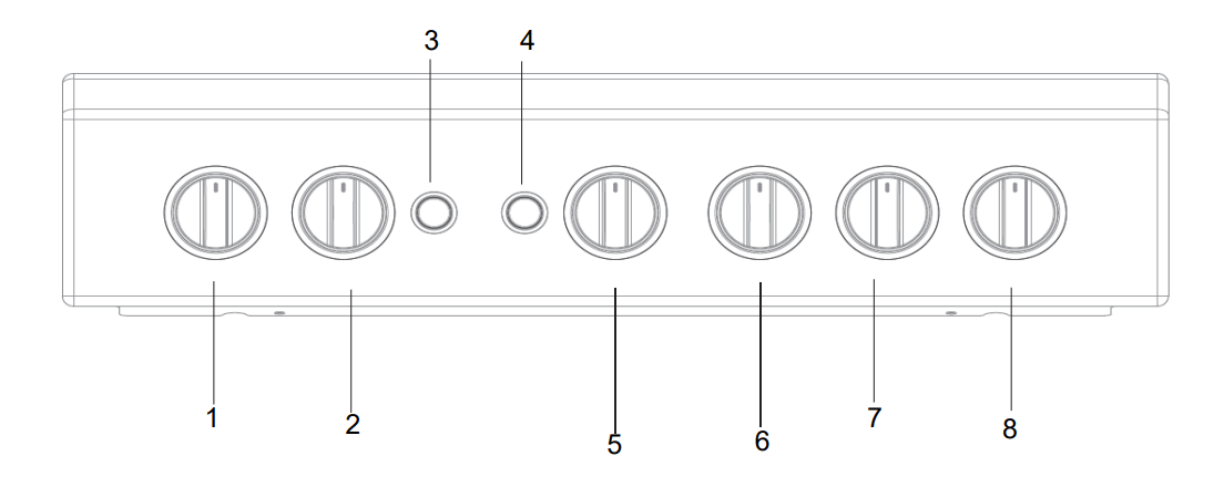
CONTROL PANEL
Control Knobs for Gas Burners on Hob
Control Knobs for Gas Burners on Hob
Button for Oven Light
Ignition button
Oven and Grill Control Knob
Timer Knob
Control Knobs for Gas Burners on Hob
Control Knobs for Gas Burners on Hob
WARNING : This operation must be perfomed by a qualified technician
INSTALLATION TIPS
Positioning
This unit may be installed and used only in permanently ventilated rooms according to the British Standards Codes Of Practice: B.S. 6172/B.S. 5440, Par. 2 and B.S. 6891 Current Editions. The following requirements must be observed:
The cooker should not be installed in a bed sitting room with a volume of less than 20m3 . If it is installed in a room of volume less than 5m3 an air vent of effective area of 100cm2 is required, if it is installed in a room of volume between 5m3 and 10m3 a supplementary airvent area of 50cm2 is required, if the volume exceeds 10m3 no airvent is required. However, if the room has a door or a window which opens directly to the outside no air vent is required even when the volume is between 5m3 and 10m3 The room containing the appliance must contain an openable window or an acceptable alternative such as an adjustable louvre or hinged panel opening direct to outside air.
During prolonged use of the appliance you may consider it necessary to open a window to the outside to improve ventilation.
If there are other fuel burning appliances in the same room, B.S.5440 Part 2 Current Edition, should, be consulted to determine the requisite air vent. The height of the cooker can be adjusted by means of adjustable feet in the plinth (900mm - 915mm). Adjust the feet by tilting the cooker from the side. Then install the product into position.
The appliance must not be installed behind a decorative door in order to avoid overheating
This appliance must not be fitted on a platform
The cooker is designed to fit between kitchen cabinets spaced 500mm apart. The space either side need only be sufficient to allow withdrawal of the cooker for servicing. It can be used with cabinets one side or both as well as in a corner setting. It can also be used free-standing.
Adjacent side walls which project above hob level, must not be nearer to the cooker than 150mm or 65mm and should be protected by heat resistant material. Any overhanging surface or cooker hood should not be nearer than 750mm.
The cooker may be located in a kitchen, a kitchen/ diner or bed sitting room, but not in a bathroom or shower room.
The hoods must be installed according to the requirements in the hood handbook.
The wall in contact with the back of the cooker must be of flameproof material.
The cooker is fitted with a safety chain that must be attached to a hook, secured to the wall behind the appliance
Gas connection
The cooker should be connected to the gas-supply by a gas safe registered installer. During installation of this product it is essential to fit an approved gas tap to isolate the supply from the appliance for the convenience of any subsequent removal or servicing. The appliance must not be installed behind a decorative door in order to avoid overheating Connection of the appliance to the gas mains or liquid gas must be carried out according to the prescribed regulation in force, and only after it is ascertained that it is adaptable to the type of gas to be used. If not, follow the instructions indicated in the paragraph headed “Adaptation to different gas types”. On some models the gas supply can be connected on the left or on the right, as necessary; to change the connection, reverse the position of the hose holder with that of the cap and replace the gasket (supplied with the appliance). In the case of connection to liquid gas, by tank, use pressure regulators that conform to the regulation in force. The gas supply must be connected to the left of the appliance. Be sure that the hose does not pass through the rear of the cooker touching hot parts.
Make sure the supply pressure conforms with the values shown in the table entitled “Caracteristics of the burners and nozzles”. When the cooker is installed between cabinets (recessed), the gas connection must be effected by an approved flexible hose with bayonet fitting (BS 669 Current Edition). The gas inlet for the cookers is a threaded G 1/2 gas female fitting.
Adapting to different types of gas
It is possible to adapt the appliance to a type of gas other than the default type (this is indicated on the rating label on the cover).
Adapting the hob
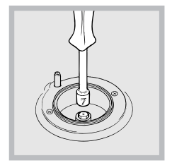
Replacing the nozzles for the hob burners:
Remove the hob grids and slide the burners off their seats.
Unscrew the nozzles using a 7 mm socket spanner ( see figure), and replace them with nozzles suited to the new type of gas(see Burner and nozzle specifications table).
Replace all the components by following the above instructions in reverse.
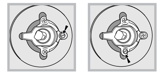
Adjusting the hob burners’ minimum setting:
Turn the tap to the minimum position.
Remove the knob and adjust the regulatory screw, which is positioned inside or next to the tap pin, until the flame is small but steady. If the appliance is connected to a liquid gas supply, the bypass screw must be set to a minimum.
While the burner is alight, quickly change the position of the knob from minimum to maximum and vice versa several times, checking that the flame is not extinguished.
Upon completion of adjustment, reseal using sealing wax or an equivalent material
The hob burners do not require primary air adjustment.
After adjusting the appliance so it may be used with a different type of gas, replace the old rating label with a new one which corresponds to the new type of gas (these labels are available from Authorised Technical Assistance Centres).
Should the gas pressure used be different (or vary slightly) from the recommended pressure, a suitable pressure regulator must be fitted to the inlet hose in accordance with current standards EN 88-1 and EN 88-2 relating to “regulators for channelled gas”.
! The hob burners do not require primary air adjustment.
! After adjusting the appliance so it may be used with a different type of gas, replace the old rating label with a new one that corresponds to the new type of gas (these labels are available from Authorised Technical Assistance Centres).
! Should the gas pressure used be different (or vary slightly) from the recommended pressure, a suitable pressure regulator must be fitted to the inlet hose in accordance with current national regulations relating to “regulators for channelled gas”.
Adapting the oven
Replacing the oven burner nozzle:
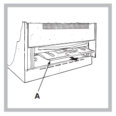
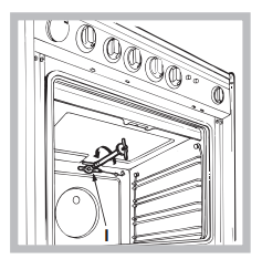
Remove the oven compartment
Slide out the protection panel A
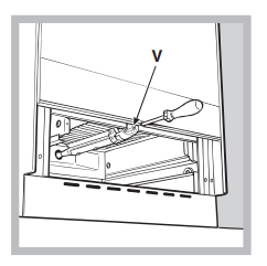
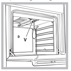
Remove the oven burner after unscrewing the screws V (see figure ). The whole operation will be made easier if the oven door is removed.
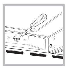
Unscrew the nozzle using a special nozzle socket spanner (see figure ) or with a 7 mm socket spanner, and replace it with a new nozzle that is suited to the new type of gas (see Burner and nozzle specifications table ).
Adjusting the gas oven burner’s minimum setting:
Light the burner ( see Start-up and Use ).
Turn the knob to the minimum position (MIN) after it has been in the maximum position (MAX) for approximately 10 minutes.
Remove the knob.
Tighten or loosen the adjustment screws on the outside of the thermostat pin ( see figure ) until the flame is small but steady. ! If the appliance is connected to liquid gas, the bypass screw must be adjusted to minimum. Upon completion of adjustment, reseal using sealing wax or an equivalent material.
Turn the knob from the MAX position to the MIN position quickly or open and shut the oven door, making sure that the burner is not extinguished.
Adapting the grill
Replacing the grill burner nozzle:
Remove the oven burner after loosening screw V ( see figure )
Unscrew the grill burner nozzle using a special nozzle socket spanner ( see figure ) or preferably with a 7 mm socket spanner, and replace it with a new nozzle that is suited to the new type of gas ( see Burner and nozzle specifications table ).
! Be careful of the spark plug wires and the thermocouple tubes.
! The oven and grill burners do not require primary air adjustment.
! After adjusting the appliance so it may be used with a different type of gas, replace the old rating label with a new one that corresponds to the new type of gas (these labels are available from Authorised Technical Assistance Centres).
! Should the gas pressure used be different (or vary slightly) from the recommended pressure, a suitable pressure regulator must be fitted to the inlet hose in accordance with current national regulations relating to “regulators for channelled gas”.
MAINTENANCE AND CLEANING
Respecting and conserving the environment
Whenever possible, avoid pre-heating the oven and always try to fill it. Open the oven door as little as possible because heat is lost every time it is opened. To save a substantial amount of energy, simply switch off the oven 5 to 10 minutes before the end of your planned cooking time and use the heat the oven continues to generate.
Keep gaskets clean and tidy to prevent any door energy losses
If you have a timed tariff electricity contract, the “delay cooking” option will make it easier to save money by moving operation to cheaper time periods.
The base of your pot or pan should cover the hot plate. If it is smaller, precious energy will be wasted and pots that boil over leave encrusted remains that can be difficult to remove.
Cook your food in closed pots or pans with well-fitting lids and use as little water as possible. Cooking with the lid off will greatly increase energy consumption
Use purely flat pots and pans
If you are cooking something that takes a long time, it's worth using a pressure cooker, which is twice as fast and saves a third of the energy
Switching the appliance off
Disconnect your appliance from the electricity supply before carrying out any work on it.
Inspecting the oven seals
Check the door seals around the oven periodically. If the seals are damaged, please contact your nearest Authorised After-sales Service Centre. We recommend that the oven is not used until the seals have been replaced.
Gas tap maintenance
Over time, the taps may become jammed or difficult to turn. If this occurs, the tap must be replaced.
! This procedure must be performed by a qualified technician who has been authorised by the manufacturer.
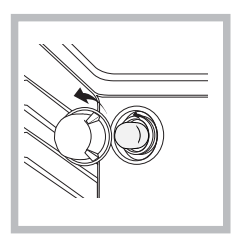
Replacing the oven light bulb
After disconnecting the oven from the electricity mains, remove the glass lid covering the lamp socket ( see figure).
Remove the light bulb and replace it with a similar one: voltage 230 V, wattage 25 W, cap E 14.
Replace the lid and reconnect the oven to the electricity supply
! Do not use the oven lamp as/for ambient lighting.
Assistance
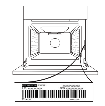
Please have the following information handy:
The appliance model (Mod.).
The serial number (S/N).
This information can be found on the data plate located on the appliance and/or on the packaging.
AFTER-SALES SERVICE
To receive assistance, call the number given on the warranty leaflet enclosed with the product or follow the instructions on our website. Be prepared to provide:
a brief description of the problem;
the exact model type of your product;
the assistance code (the number following the word SERVICE on the identification plate attached to the product, which can be seen on the inside edge when the oven door is open);
your full address;
a contact telephone number.
Please note: If repairs are required, contact an authorised service center that is guaranteed to use original spare parts and perform repairs correctly. Please refer to the enclosed warranty leaflet for more information on the warranty.
REMOVING AND REFITTING THE DOOR
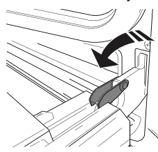
To remove the door, open it fully and lower the catches until they are in the unlock position.
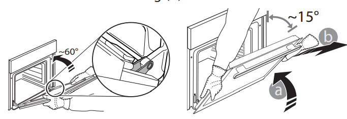
Close the door as much as you can. Take a firm hold of the door with both hands – do not hold it by the handle. Simply remove the door by continuing to close it while pulling it upwards (a) at the same time until it is released from its seating (b). Put the door to one side, resting it on a soft surface.
Refit the door by moving it towards the oven, aligning the hooks of the hinges with their seating and securing the upper part onto its seating.
Lower the door and then open it fully. Lower the catches into their original position: Make sure that you lower them down completely.
Try closing the door and check to make sure that it lines up with the control panel. If it does not, repeat the steps above.
Click to clean - Clean the grass
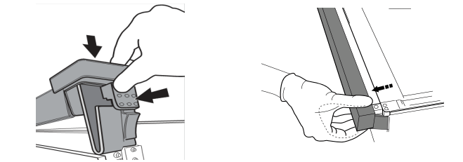
After removing the door and resting it on a soft surface with the handle downwards, simultaneously press the two retaining clips and remove the upper edge of the door by pulling it towards you.
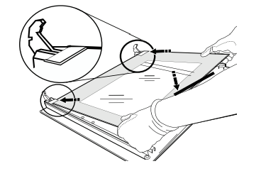
Lift and firmly hold the inner glass with both hands, remove it and place it on a soft surface before cleaning it.
When reassembling the inner door glass insert the glass panel correctly so that the text written on the panel is not reversed and can be easily legible.
Refit the upper edge: a click will indicate correct positioning. Make sure the seal is secure before refitting the door.
 Read the safety instructions carefully before using the product
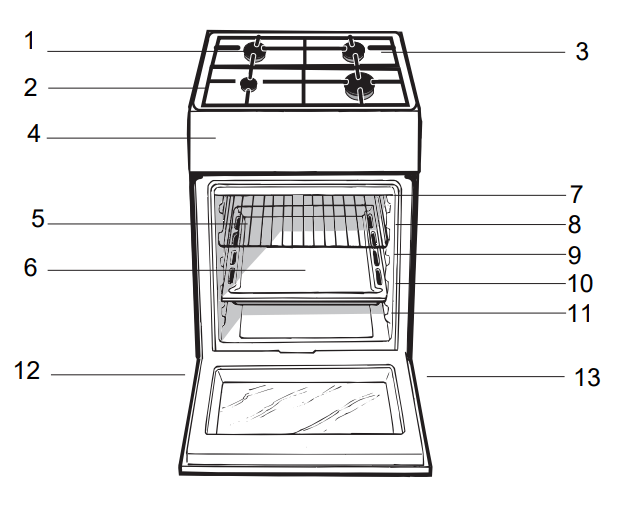
 Replacing the nozzles for the hob burners: