
YARD
OPERATOR'S MANUAL
Transmatic
Garden Tractor
Models
820 Thru 829
840 Thru 849
IMPORTANT: Read safety rules and instructions carefully before operating equipment.
Warning: This unit is equipped with an internal combustion engine and should not be used on or near any unimproved forest-
covered, brash-covered or grass-covered land unless the engine's exhaust system is equipped with a spark arrester meeting
applicable local or state laws (if any). If a spark arrester is used, it should be maintained in effective working order by the operator.
In the State of California the above is required by law (Section 4442 of the California Public Resources Code). Other states may have
similar laws. Federal laws apply on federal lands. A spark arrester for the muffler is available through your nearest engine authorized
service dealer or contact the service department, P.O. Box 368022 Cleveland, Ohio 44136-9722.
MTD PRODUCTS INC. P.O. BOX 368022 CLEVELAND, OHIO 44136-9722
ECO#2844 FORM NO. 770-10119B
PRINTED IN U.S.A. (12/2000)
TABLEOFCONTENTS
Content Page
Important Safe Operation Practices ................................................................... 3
Stope Gauge ...................................................................................................... 6
Hardware Pack .................................................................................................. 7
Unpacking .......................................................................................................... 8
Assembling Your Garden Tractor ....................................................................... 8
Know Your Garden Tractor ................................................................................ 14
Operating Your Garden Tractor ......................................................................... 16
Making Adjustments .......................................................................................... 18
Maintaining Your Garden Tractor ....................................................................... 21
Off-Season Storage ........................................................................................... 23
Optional Equipment ........................................................................................... 24
Troubleshooting ................................................................................................. 25
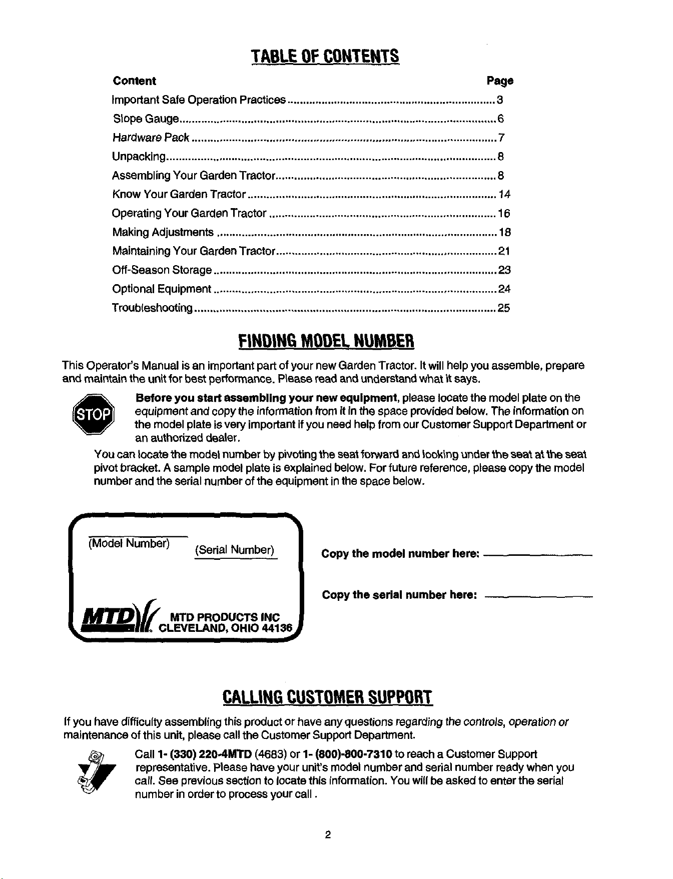
FINDINGMODELNUMBER
This Operator's Manual is an important part of your new Garden Tractor. It will help you assemble, prepare
and maintain the unit for best performance. P_ease read and understand what it says.
Before you start assembling your new equipment, please locate the model plate on the
equipment and copy the information from it inthe space provided below. The information on
the model plate is very important if you need help from our Customer Support Department or
an authorized dealer.
You can locate the model number by pivoting the seat fo_ard and looking under the seat at the seal
pivot bracket. A sample model plate is explained below. For future reference, please copy the model
number and the serial number of the equipment in the space below.
I mlmll I I
(Model Number) (Serial Number)
!
Copy the model number here:
Copy the serial number here:
CALLINGCUSTOMERSUPPORT
If you have difficulty assembling this product or have any questions regarding the controls, operation or
maintenance of this unit, please call the Customer Support Department.
Call 1- (330) 220_IMTD (4683) or 1- (800)-800-7310 to reach a Customer Support
representative. Please have your unit's model number and serial number ready when you
call. See previous section to locate this information. You will be asked to enter the serial
number in order to process your call.
2

SECTION1: IMPORTANTSAFEOPERATIONPRACTICES
WARNING: This symbol points out important safety instructions which, if not followed, could endanger
the personal safety and/or property of yourself and others, read and follow all instructions in this manual
before attempting to operate your lawn mower, failure to comply with these instructions may result in
personal injury. When you see this symbol, heed itswaming.
WARNING: The Engine Exhaust from this product contains chemicals known to the State of California
to cause cancer, birth defects or other reproductive harm.
DANGER: Your lawn mower was built to be operated according to the rulesfor safe operation in this manual. As
with any type of power equipment, carelessness or error on the part of the operator can result in serious injury. This
lawn mower is capable of amputating hands and feet and throwing objects. Failure to observe the following safety
instructions could result in serious injuryor death.
GeneralOperation
• Read, understand, and follow all instructions in the
operator's manual and on the machine before
starting. Keep this manual in a safe place for future
and regular reference and for ordering replacement
parts.
• Only allow responsible individuals familiar with the
instructions to operate the machine. Know controls
and how to stop the machine quickly.
• Do not put hands or feet under cutting deck or near
rotating parts.
• Clear the area of objects such as rocks, toys, wire,
etc., which could be picked up and thrown by the
blade. A small object may have been overlooked
and could be accidentally thrown by the mower in
any direction and cause injury to you or a
bystander. To help avoid a thrown objects injury,
keep children, bystanders and helpers at least 75
feet from the mower while it is in operation. Always
wear safety glasses or safety goggles dudng
operation or while performing an adjustment or
repair, to protect eyes from foreign objects. Stop
the blade(s) when crossing gravel drives, walks or
roads.
• Be sure the area is clear of other people before
mowing. Stop machine if anyone enters the area.
• Never carry passengers.
• Disengage blade(s) before shifting into reverse and
backing up. Always look down and behind before
and while backing.
• Be aware of the mower and attachment discharge
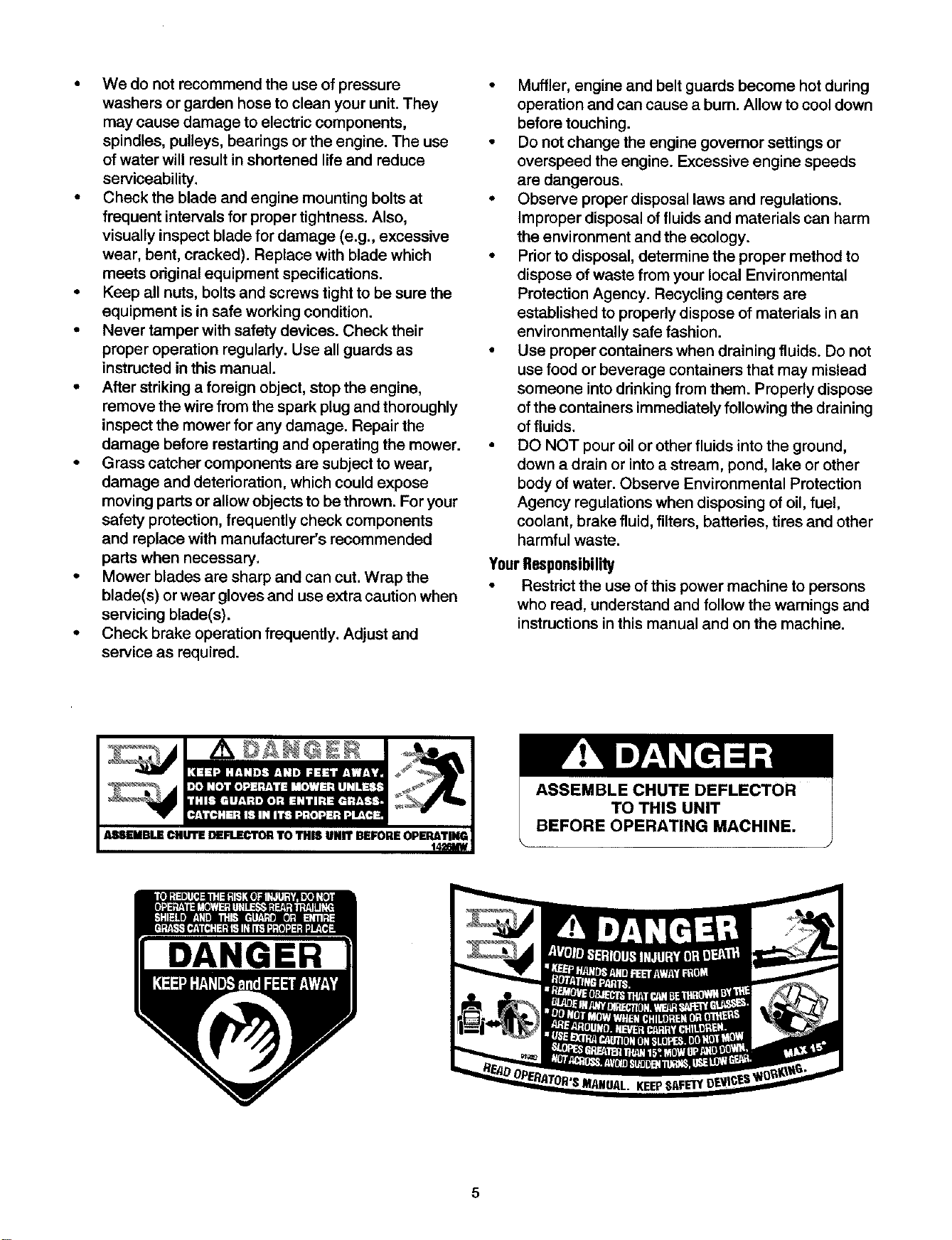
direction and do not point it at anyone. Do not
operate the mower without either the entire grass
catcher or the chute guard in place.
• Slow down before turning. Operate the machine
smoothly. Avoid erratic operation and excessive
speed.
• Never leave a running machine unattended.
Always turn off blade(s), place transmission in
neutral, set park brake, stop engine and remove
key before dismounting.
• Turn off blade(s) when not mowing.
• Stop engine and wait until blade(s) comes to a
complete stop before (a) removing grass catcher or
unclogging chute, or (b) making any repairs,
adjusting or removing any grass or debds.
• Mow only in daylight or good artificial light.
• Do not operate the machine while under the
influence of alcohol or drugs.
• Watch for traffic when operating near or crossing
roadways.
• Use extra care when loading or unloading the
machine into a trailer or truck. This unit should not
be driven up or down a ramp onto a trailer or truck
under power, because the unit could tip over,
causing serious personal injury. The unit must be
pushed manually on a ramp to load or unload
properly.
• Never make a cutting height adjustment while
engine is running if operator must dismount to do
SO.
• Wear sturdy, rough-soled work shoes and close-
fitting slacks and shirts. Do not wear loose fitting
clothes or jewelry. They can be caught in moving
parts. Never operate a unit in bare feet, sandals, or
sneakers.
• Check overhead clearance carefully before driving
under power lines, wires, bridges or low hanging
tree branches, before entering or leaving buildings,
or in any other situation where the operator may be
struck or pulled from the unit, which could result in
serious injury.
• Disengage all attachment clutches, thoroughly
depress the brake pedal, and shift into neutral
before attempting to start engine.
• Your mower is designed to cut normal residential
grass of a height no more than 10". Do not attempt
to mow through unusually tall, dry grass (e.g.,
pasture) or piles of dry leaves. Debris may build up
on the mower deck or contact the engine exhaust
presenting a potential fire hazard.
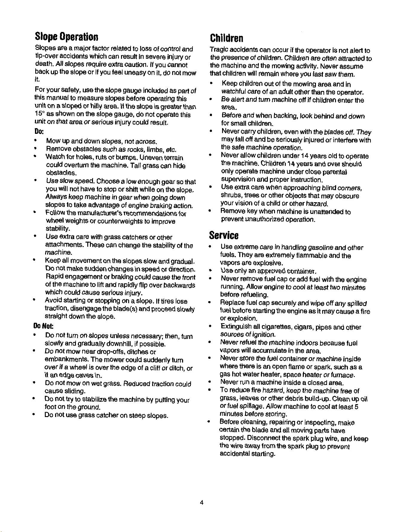
SlopeOperation
SIopee are a major factor related to loss of control and
tip-over accidents which can result in severe injury or
death. All slopes require extra caution. If you Cannot
back up the slope or if you feel uneasy on it, do not mow
it.
For your safety, use the slope gauge _nctuded as part of
this manual to measure slopes before operating this
uW_ton a s_oped or billy area. It the slope is greater than
15° as shown on the slope gauge, do not operate this
unit on that area or serious injury could result.
DO:
• Mow up and down slopes, not across.
• Remove obstacles such as rocks, limbs, etc.
- W__tohfor _olas, ruts or bumps. Uneven tarrain
could overturn the machine. Tall grass can hide
obstacles.
• Use slow speed. Choose a low enough gear so that
you will not have to stop or shift while on the slope.
Always keep machine in gear when going down
slopes to take advantage ofengine braking action.
• FollOW the manufactureT's recommendat_,m'_s for
wheel weights or counterweights to improve
stability.
• Use extra care with grass catchers or other
attachments. These can change the stability of the
machine.
• Keep all movement on the slopes slow and gradual.
Do r_tmake sudden ohanges'm spee_ or(_r_on.
Rapid engagement or braking could cau,_e the front
of the machine to lift and rapidly flip over I_ackwards
which could cause serious injury.
• Avoid starting or stopping on a slope. If tires lose
traction, disengage the blade(s) and proceed slowly
straight down the slope.
DoNot:
• Do not turn on slopes unless necessary; then, turn
slowly and gradually downhill, ifpossible.
• Do not mow near drop-offs, ditches or
embankments. The mower could suddenly turn
over if a wheel is over the edge of a cliff or ditch, or
"_tan edQjeca0tes _r_.
• Do not mow on wet grass. Reduced traction could
cause sliding.
• [3o not try to stabilize the machine by putting your
foot on the ground.
• [30 not use grass catcher on steep slopes.
Children
Tragic accidents can oCcur ifthe operator is not alert to
the presence of children. Children are often attracted to
the machine and the mowing activity. Never assume
that children will remain where yOulasf saw them.
• Keep children out of the mowing area and in
watchful care of an adult other than the operator.
• Be alert and turn machine off if chJldran enter the
ate'&.
• Before and when backing, look behind and down
for small children.
• Never carry children, even with the b/aries off. They
may fall off and be seriously injured or interfere with
the safe machine operation.
• Never allow children under 14 years old to operate
the machine. (3_ldren 14 yeats an_ OVBTShOU_
only operate machine under dose parental
supervision and p_Operinstruction.
• Use extra care when approaching blind corners,
shrubs, trees or other objects that may obscure
your vision of a child or other hazard.
• Remove key when machine is unattended to
prevent unauthor)zed operation.
Service
• Use extreme care In handling gasoline and other
fuels. They are extremely flammable and the
vapors are explosive.
• _&seon_,yan appTu_e_ co_ne_.
• Never remove fuel cap or add fuel with the engine
running. Allow engine to cool at least two minutes
before refueling.
• Replace fuel cap securely and wipe off any spilled
fuel before starting the engine as it may cause a fire
or explosion.
• Extinguish all cigarettes, cigars, pipes and other
sources of ignition.
• Never refuel the machine indoors because fuel
vapors will accumulate in the area.
• Never store the fuel container or machine inside
where there is an open flame or spark, such as a
gas hot water heater, space heater or furnace.
• Never run a machine inside a closed area.
• To reduce fire hazard, keep the machine free of
grass, leaves or other debris bui{d-up.Clean up ei_
or fuel spillage. Allow machine to cool at least 5
minutes before storing.
• Before cleaning, repairing or inspecting, make
certain the bladeand allmoving parts have
stopped. Disconnect the spark plug wire, and keep
the wire avery _rem the spaTk plug to prevent
accidental starting.
4
• We do not recommend the use of pressure
washers or garden hose to clean your unit. They
may cause damage to electric components,
spindles, pulleys, bearings or the engine. The use
of water will result in shortened life and reduce
serviceability.
• Check the blade and engine mounting bolts at
frequent intervals for proper tightness. Also,
visually inspect blade for damage (e.g., excessive
wear, bent, cracked). Replace with blade which
meets odginal equipment specifications.
• Keep all nuts, bolts and screws tight to be sure the
equipment is in safe working condition.
• Never tamper with safety devices. Check their
proper operation regularly. Use all guards as
instructed in this manual.
• After striking a foreign object, stop the engine,
remove the wire from the spark plug and thoroughly
inspect the mower for any damage. Repair the
damage before restarting and operating the mower.
• Grass catcher components are subject to wear,
damage and deterioration, which could expose
moving parts or allow objects to be thrown. For your
safety protection, frequently check components
and replace with manufacturer's recommended
parts when necessary.
• Mower blades are sharp and can cut. Wrap the
blade(s) or wear gloves and use extra caution when
servicing blade(s).
• Check brake operation frequently. Adjust and
service as required.
• Muffler, engine and belt guards become hot during
operation and can cause a burn. Allow to cool down
before touching.
• Do not change the engine governor settings or
overspeed the engine. Excessive engine speeds
are dangerous.
• Observe proper disposal laws and regulations.
Improper disposal of fluids and materials can harm
the environment and the ecology.
• Prior to disposal, determine the proper method to
dispose of waste from your local Environmental
Protection Agency. Recycling centers are
established to propedy dispose of materials in an
environmentally safe fashion.
• Use proper containers when draining fluids. Do not
use food or beverage containers that may mislead
someone into drinking from them. Properly dispose
of the containers immediately following the draining
of fluids.
• DO NOT pour oil or other fluids into the ground,
down a drain or into a stream, pond, lake or other
body of water. Observe Environmental Protection
Agency regulations when disposing of oil, fuel,
coolant, brake fluid, filters, batteries, tires and other
harmful waste.
YourResponsibility
• Restrict the use of this power machine to persons
who read, understand and follow the warnings and
instructions in this manual and on the machine.
ASSEMBLE CHUTE DEFLECTOR
TO THIS UNIT
BEFORE OPERATING MACHINE.
DANGER
5
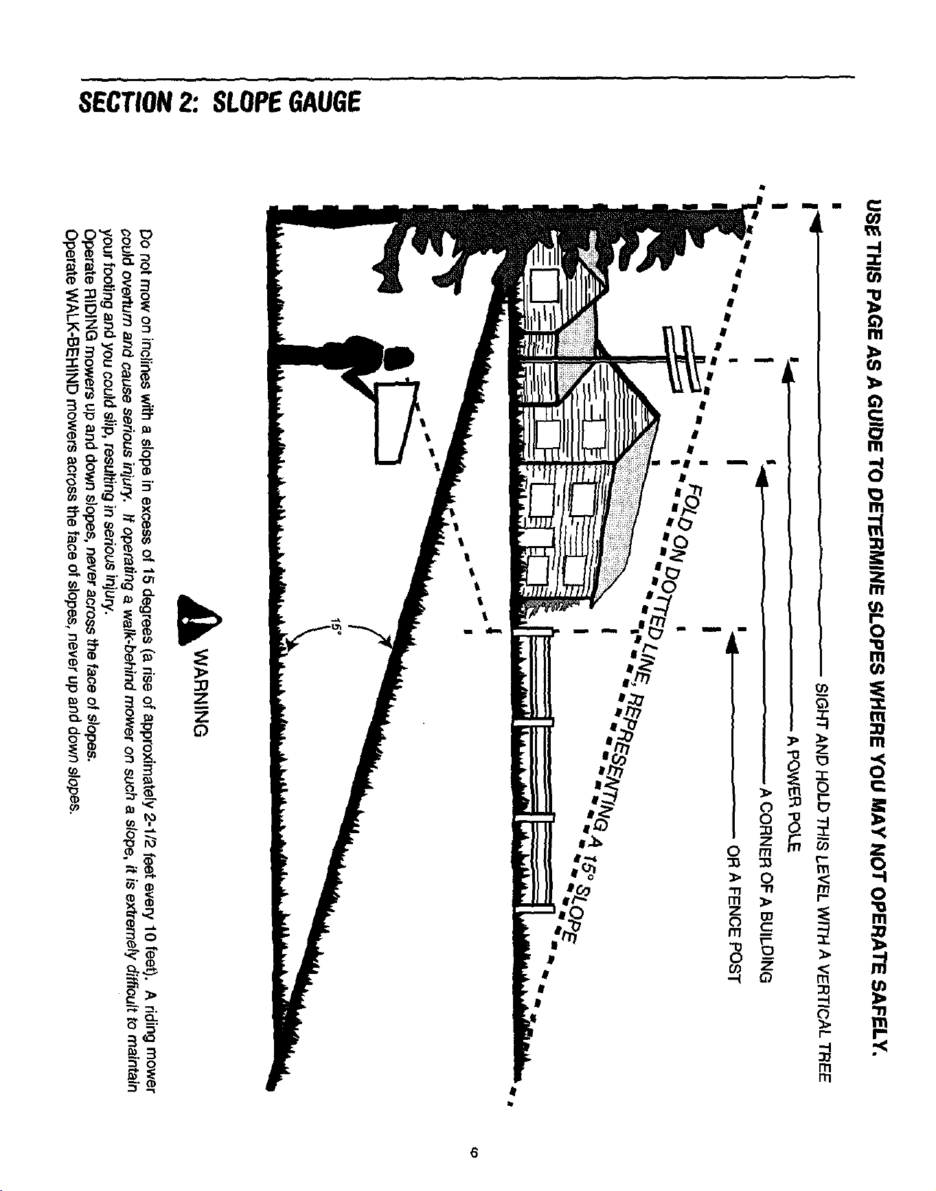
USE THIS PAGE AS A GUIOE TO DETERMINE SLOPES WHERE YOU MAY NOT OPERATE SAFELY,
I
I _ - -- SIGHT AND HOLD THIS LEVEL WITH A VERTICAL TREE
I I_ A P(3W_R POLE
Ii i_ ..... A CORNER OF A BUILDING
I i _ OR A FENCE POST
I"w II • i},
_ll_ _ lU_
_WARNING
DO not mow on inclines with a slope in excess of 15 degrees (a rise of approximately 2-1/2 feet every 10 feet). A riding mower
I,.- could overturn and cause senous injury. If operating a walk-behind mower on suCh a slope, it is extremely difficult to maintain
your footing and you could slip, resulting in serious injury.
Operate RIDING mowers up and down slopes, never across the face of slopes.
Operate WALK-BEHIND mowers across the face of slopes, never up and down slopes.
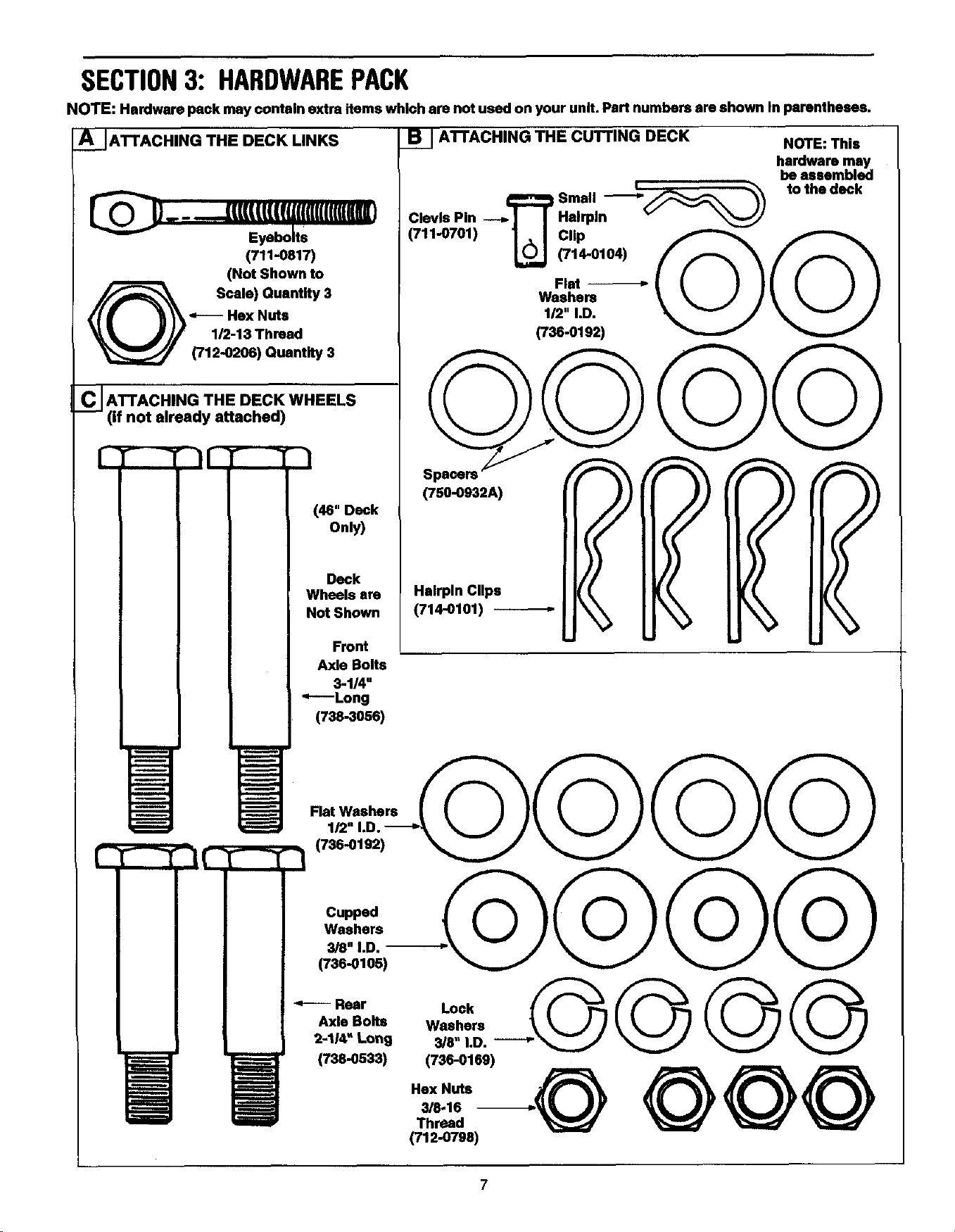
SECTION3: HARDWAREPACK
NOTE: Hardware pack may contain oxtm items which are not used on your unit. Part numbers are shown In pamntheees.
A J ATTACHING THE DECK LINKS
)..--..mmmfU.mmmm)
Eyebolts
(711-0817)
(Not Shown to
Scale) Quantity 3
Hex Nuts
1/2-13 Thread
(712-0206) Quantity 3
C JATTACHING THE DECK WHEELS
(if not already attached)
M
m
i
(46" Deck
Only)
Deck
Wheels are
Not Shown
Front
Axle Bolts
3-1/4"
"----Long
(738-3056)
131 ATrACHING THE CUTTING DECK
NOTE: This
hardware may
be assembled
Small -__ _ to the deck
Clevis Pin ---,. I I Hairpin v
(711-0701) _] _ Weehe.ll/2.Flat(714-0104)CliPi.D._@ @
(736-0192)
(750-0932A)
Hairpin Clips
(714-0101)
m
m
i
m
m
ramming
=tram:
m
Flat Washers
(736-0192)
-'+-----Rear Lock----+G @ @ @
Axle Bolts Washers
2-114" Long 3/8" I.D.
(73e-0533) (736-0169)
Hex Nuts +,.@ @@@
3/8-16 --
Thread
(712-0798)
7
SECTION4: ASSEMBLINGYOURGARDENTRACTOR
Unpacking
• Remove a|t screws and staples from top ot orate
using a 1/4" hex head socket or a screw driver.
• To remove ends, grasp top board on the end, and
pull towards you in a downward motion.
(A hammer may be helpful).
• Set panel aside to avoid tire punctures.
• Repeat procedure for each side of the crate.
• Remove and discard plastic bag which covers unit.
• Loose parts (may include the operator's manual,
steering wheel, battery fluid, chute deflector, etc.)
are on the seat or in a box and wrapped in plastic.
Carefully cut and remove the ptastic wrap. Remove
loose parts from the seat.
• Remove the deck from beneath the tractor. Make
certainparkingbrokeisreleasedand unitisin
neutral. See the controlssection of this manual for
location of the pa_ing brake release and the shift
lever. Push unitoff of the skid.
• Lay out the contents of the hardware pack on the
illustration on page 7 for identification.
IMPORTANT- After assembly, service engine with
gasoline, and check oil level as instructed in the
separate engine manual packed with your unit.
NOTE: Reference to right or left hand side of the unit is
observed from the driver's seat, facing forward.
ToolsRequired
1. 1/4" socket wrench or fiat blade screwdriver
2. 1/2" wrench or socket wrench*
3. 9/16" wrench or socket wrench
4. Two 7/16" wrenches or socket wrenches
*IfyoursteeringwheelcapIssquare,youmusthaveasocketwrench
Inorderto InstallIhesteeringwheel.
SettinguptheBattery
il_ WARNING: Always shield eyes, protect
skin and clothing when working near batteries.
WARNING: Battery acid must be handled
with greet care as contact with it can burn and
blister the skin. Follow the steps below to
ensure safe handling.
a.
b.
Wear protective clothing (goggles, rubber gloves
and apron) when working with the battery.
Should battery acid accidentally splatter into the
eyes or onto the face, rinse the affected area
immediately with clean cold water. A list of
antidotes are given below. If there isany further
discomfort, seek medical attention.
Antidote: EXTERNAL--Flush with water.
iNTEP,Nk,L--(3rir_. large _ua_t_.ti._e_ water
or milk. Follow with milk of magnesia, beaten
eggs or vegetable oil. Call physician immedi-
ately.
EYES: Flush with cool water for at least 15
minutes, then get prompt medical attention.
c. If acid spills on clothing, first dilute itwith clean
water, then neutralize with a solution of ammonia/
water or baking soda/water.
d. Since battery acid is corrosive, do not pour it into
any sinkor drain. Before discarding empty
electrolyte containers, rinse them with a
neutralizing solution.
e. NEVER connect or disconnect charger clips to
battery while charger is turned on as it can cause
sparks.
f. Keep alllighted materials _cigarettee, matches,
lighters) away from the battery as the hydrogen gas
generated during charging can be combustible.
g. As a further precaution, only charge the battery in a
well-ventilated area.
A
WARNING: Keep battery out of the reach of
children.
WARNING: Do not activate battery (fill with
battery acid) until battery is actually placed in
service. Be certain to read previous battery
warnings before activating the battery.
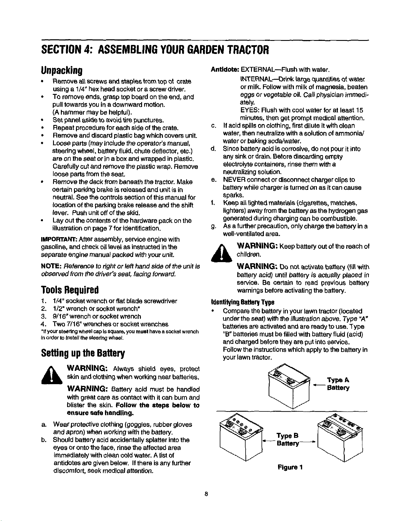
Identifying 6atte_ Type
• Compare the battery in your lawn tractor (located
under the seat) with the illustrationabove. Type "A"
batteries are activated and are ready to use. Type
"B" batteries must be filled with battery fluid (acid)
and charged before they are put irtt_ serv{ce.
Follow the instructionswhich apply to the battery in
your lawn tractor,
__ Type A
Battery
Figure I
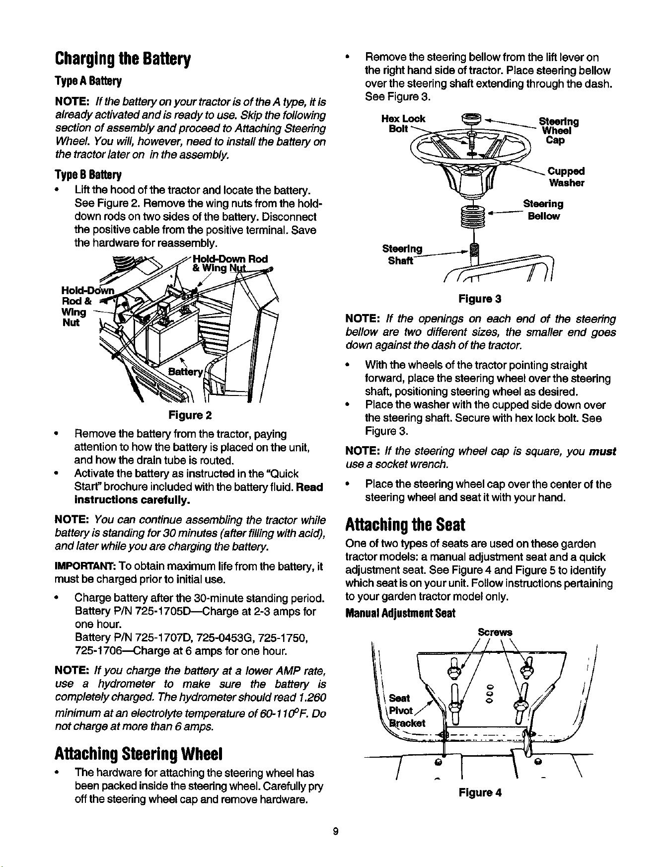
ChargingtheBattery
Type ABattery
NOTE: ff the battery on your tractor is of theA type, itis
already activated and is ready to use. Skip the following
section of assembly and proceed to Attaching Steering
Wheel. You will, however, need to instafl the battery on
the tractor later on in the aseembly.
Type BBattery
• Lift the hood of the tractor and locate the battery.
See Figure 2. Remove the wing nuts from the hold-
down rods on two sides of the battery. Disconnect
the positive cable from the positive terminal. Save
the hardware for reassembly.
Figure 2
Remove the steering bellow from the lift lever on
the right hand side of tractor. Place steering bellow
over the steering shaft extending through the dash.
See Figure 3.
He)( Lock _ _ Steedno
Bolt - _ Wheel"
Cap
Cupped
_ Washer
Steering
Bellow
Steerlng
Shaft
Hold-DoWn
Rod &
Wing
Nut
• Remove the battery from the tractor, paying
attention to how the battery is placed on the unit,
and how the drain tube is muted.
• Activate the battery as instructed in the "Quick
Start" brochure included withthe battery fluid. Read
instructions carefully.
NOTE: You can continue assembling the tractor while
battery isstanding for 30 minutes (after fillingwith acid),
and later while you are charging the battery.
IMPORTANT: To obtain maximum lifefrom the battery, it
must be charged prior to initial use.
Charge battery after the 30-minute standing period.
Battery P/N 725-1705D_Charge at 2-3 amps for
one hour.
Battery PIN 725-1707D, 725-0453G, 725-1750,
725-1706--Charge at 6 amps for one hour.
NOTE: If you charge the battery at a lower AMP rate,
use a hydrometer to make sure the battery is
completely charged. The hydrometer should read 1.260
minimum at an electrolyte temperature of 60-110 ° F. Do
not charge at more than 6 amps.
AttachingSteeringWheel
• The hardware for attaching the steering wheel has
been packed inside the steering wheel. Carefully pry
off the steering wheel cap and remove hardware.
Figure 3
NOTE: ff the openings on each end of the steering
bellow are two different sizes, the smaller end goes
down against the dash of the tractor.
• With the wheels of the tractor pointing straight
forward, place the steering wheel over the steering
shaft, positioning steering wheel as desired.
• Place the washer with the cupped side down over
the steering shaft. Secure with hex lock bolt. See
Figure 3.
NOTE: ff the steering wheel cap is square, you must
use a socket wrench.
• Place the steering wheel cap over the center of the
steering wheel and seat it with your hand.
AttachingtheSeat
One of two types of seats are used on these garden
tractor models: a manual adjustment seat and a quick
adjustment seat. See Figure 4 and Figure 5 to identify
which seat ison your unit. Follow instructions pertaining
to your garden tractor model only.
ManuelAdjustmentSeat
Screws
ir
Figure 4
9
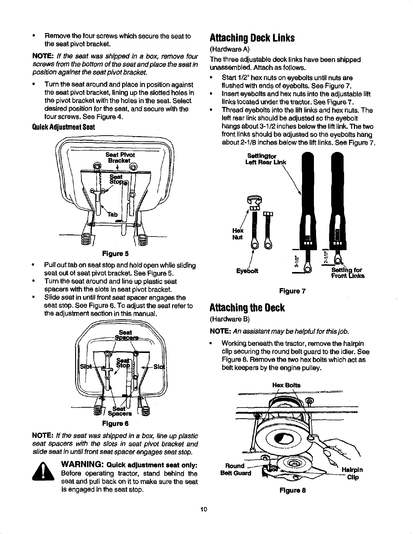
• Remove the tour screws which secure the seat to
the seat pivot bracket.
NOTE: If the seat was shipped in a box, remove four
screws from the bottom of the seat and place theseat in
position against the seat pivot bracket.
Turn the seat around and place in positionagainst
the seat pivot bracket, liningup the slotted holes in
the pivotbracket with the holes inthe seat. Select
desired position for the seat, and secure with the
four screws. See Figure 4.
QuickAdjustmentSeat
Figure 5
• Pull out tab on seat stop and hold open while sliding
seat out of seat pivot bracket. See Figure 5.
• Turn the seat around and line up plastic seat
spacers with the slots in seat pivot bracket.
• Slide seat in until front seat spacer engages the
seat stop. See Figure 6. To adjust the seat refer to
the adjustment section in this manual.
Figure 6
NOTE: If the seat was shipped in a box, line up plastic
seat spacers with the slots in seat pivot bracket and
slide seat in until front seat spacer engages seat stop.
,_ WARNING: Quick adjustment seat only:Before operating tractor, stand behind the
seat and pull back on if to make sure the seat
is engaged in the seat stop.
AttachingDeckLinks
(Hardware A)
The three adjustable deck links have been shipped
unassembled. Attach as follows.
Q
Start 1/2" hex nuts on eyebolts until nuts are
flushed with ends of eyebolts. See Figure 7.
Insert eyebolts and hex nuts into the adjustable lift
links located under the if'actor. See Figure 7.
Thread eyebolts intothe liftlinks and hex nuts. The
left rear link should be adjusted so the eyebolt
bangs about 3-1/2 inches below the lift link,The two
front links should be adjusted so the eyebolts hang
about 2-1/8 inches below the liftlinks. See Figure 7.
_dtlngfor
Left Rear Link
Figure 7
AttachingtheDeck
(Hardware B)
NOTE: An assistant may be helpful for thisjob.
Working beneath the tractor, remove the hairpin
clip securing the round belt guard to the idler. See
Figure 8. Remove the two hex bolts which act as
belt keepers by the engine pulley.
Hex Bolts
Flgure 8
10
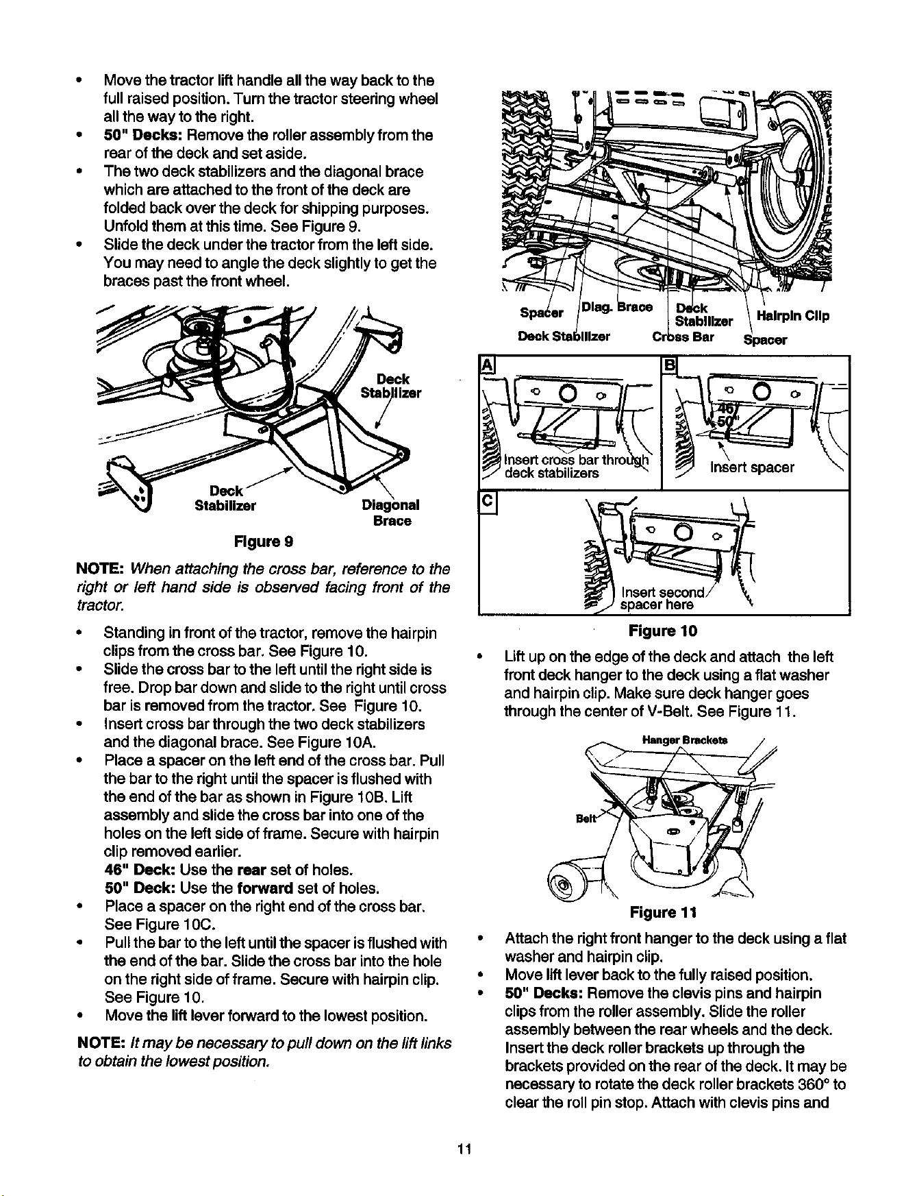
• Move the tractor lifthandle all the way back to the
full raised position. Turn the tractor steering wheel
all the way to the right.
• 50" Decks: Remove the roller assembly from the
rear of the deck and set aside.
• The two deck stabilizers and the diagonal brace
which are attached to the front of the deck are
folded back over the deck for shipping purposes.
Unfold them at this time. See Figure 9.
• Slide the deck under the tractor from the left side.
You may need to angle the deck slightly to get the
braces past the front wheel.
Deck
Ilzer
Deck
Stabilizer
Brace
Figure 9
NOTE: When attaching the cross bar, reference to the
right or left hand side is observed facing front of the
tractor.
• Standing infront of the tractor, remove the hairpin
clips from the cross bar. See Figure 10.
• Slide the cross bar to the left until the right side is
free. Drop bar down and slide to the right until cross
bar is removed from the tractor. See Figure 10.
• Insert cross bar through the two deck stabilizers
and the diagonal brace. See Figure 10A.
• Place a spacer on the left end of the cross bar. Pull
the bar to the right until the spacer isflushed with
the end of the bar as shown in Figure 10B. Lift
assembly and slide the cross bar into one of the
holes on the left side offrame. Secure with hairpin
clip removed earlier.
46" Deck: Use the rear set of holes.
50" Deck: Use the forward set of holes.
• Place a spacer on the rightend of the cross bar.
See Figure 10C.
• Pullthe bar to the left untilthe spacer is flushed with
the end of the bar. Slide the cross bar into the hole
on the right side offrame. Secure with hairpin clip.
See Figure 10.
• Move the liftlever forward to the lowest position.
NOTE: It may be necessary topull down on the lift links
to obtain the lowest position.
Deck
IInsert crossbarthrodg.h
/ deck stabilizers "
c3
Hairpin Clip
o o o Z, F--
)'npS;cerhere
Figure 10
Lift up on the edge of the deck and attach the left
front deck hanger to the deck using a flat washer
and hairpin clip. Make sure deck hanger goes
through the center of V-Belt. See Figure 11.
Figure 11
Attach the right front hanger to the deck using a flat
washer and hairpin clip.
Move lift lever back to the fully raised position.
60" Decks: Remove the clevis pins and hairpin
clips from the roller assembly. Slide the roller
assembly between the rear wheels and the deck.
Insert the deck roller brackets up through the
brackets provided on the rear of the deck. It may be
necessary to rotate the deck roller brackets 360 ° to
clear the roll pin stop. Attach with clevis pins and
11
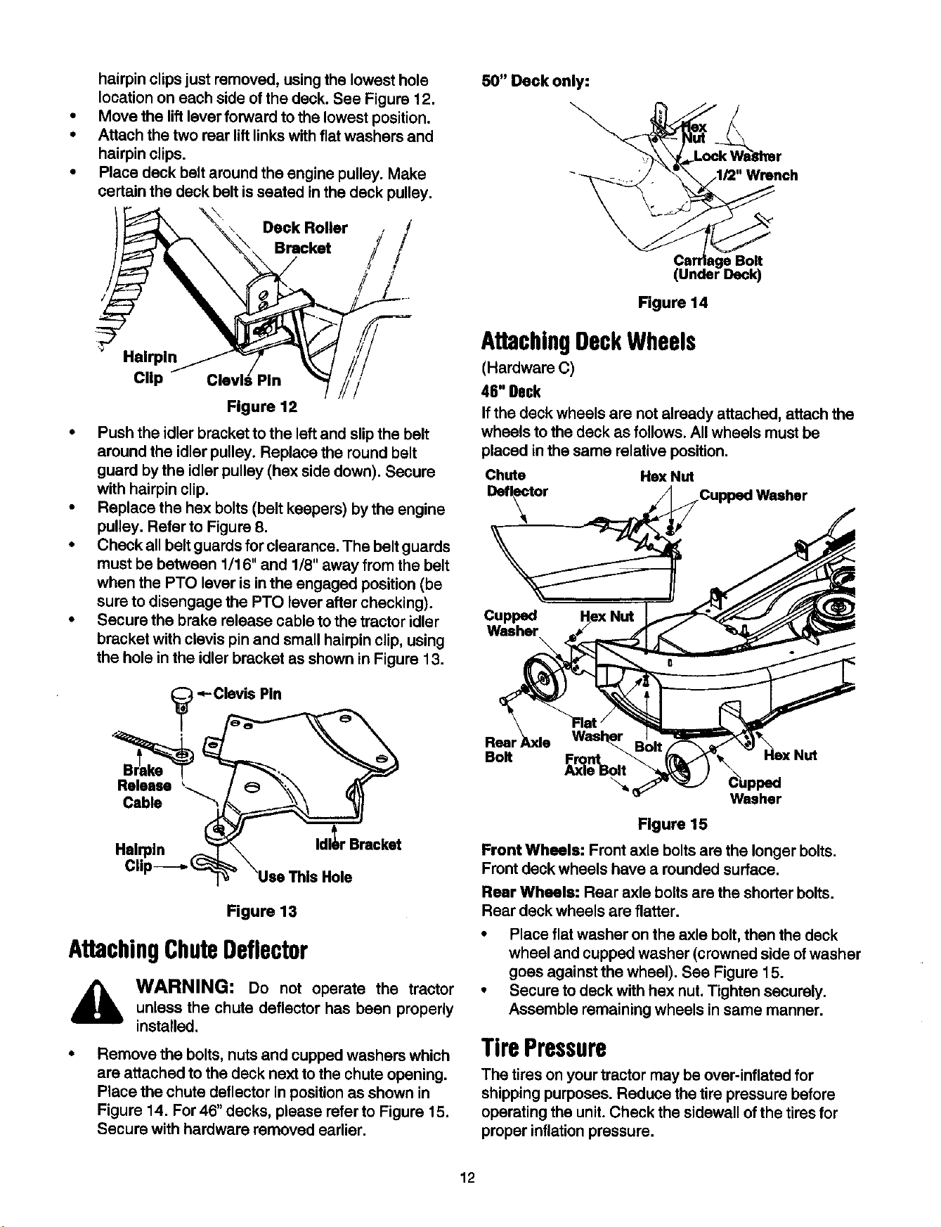
hairpin clips just removed, using the lowest hole
location on each side of the deck. See Figure 12.
Move the liftlever forward to the lowest position.
Attach the two rear lift links with flat washers and
hairpin clips.
Place deck belt around the engine pulley. Make
certain the deck belt isseated in the deck pulley.
Clip
Deck Roller /
,
Figure 12
• Push the idler bracket to the left and slip the belt
around the idler pulley. Replace the round belt
guard bythe idler pulley (hex side down). Secure
with hairpin clip.
• Replace the hex bolts (belt keepers) by the engine
pulley. Refer to Figure 8.
• Check all belt guards for clearance. The belt guards
must be between 1/16" and 1/8" away from the belt
when the PTO lever is inthe engaged position (be
sure to disengage the PTO lever after checking).
• Secure the brake release cable to the tractor idler
bracket with clevis pin and small hairpin clip, using
the hole in the idler bracket as shown in Figure 13.
Figure 13
AttachingChuteDeflector
WARNING: Do not operate the tractor
unless the chute deflector has been properly
installed.
Remove the bolts, nuts and cupped washers which
are attached to the deck next to the chute opening.
Place the chute deflector in position as shown in
Figure 14. For 46" decks, please refer to Figure 15.
Secure with hardware removed earlier.
50" Deck only:
• Bolt
(
Figure 14
AttachingDeckWheels
(Hardware C)
46" Deck
If the deck wheels are not already attached, attach the
wheels tothe deck as follows. Allwheels must be
placed in the same relative position.
Chute He}(Nut
Defector Cupped Washer
Cupped
Washer
\
Resi
Bolt
a Washer
Figure 15
Front Wheels: Front axle bolts are the longer bolts.
Front deck wheels have a rounded surface.
Rear Wheels: Rear axle bolts are the shorter bolts.
Rear deck wheels are flatter.
• Place flat washer on the axle bolt, then the deck
wheel and cupped washer (crowned side ofwasher
goes against the wheel). See Figure 15.
• Secure to deck with hex nut. Tighten securely.
Assemble remaining wheels in same manner.
TirePressure
The tires on your tractor may be over-inflated for
shipping purposes. Reduce the tire pressure before
operating the unit. Check the sidewall of the tires for
proper inflationpressure.
12
,_ WARNING: Maximum tire pressure under
any circumstances is 30 p.s.i. Equal tire
pressure should be maintained on all tires.
LevelingtheDeck
After attaching the deck to the tractor, make sure it is
adjusted properly.
• Check tire pressure of all four tires. See sidewall of
tire for recommended inflation pressure.
• Make certain all deck wheels or both ends of the
deck rollerare mounted in same relative hole
locations.Place the tractor on a level surface.
46" Deck: Lower the deck until it reaches the
ground. All four deck wheels should reach the
ground at the same time.
Place the deck approximately 1" above the ground.
The distance from the bottom edge of the deck to
the ground must be same on both sides of the deck.
AdjustingDeck Links
Ifadjustment isnecessary, adjust the deck links on the
leftside of the deck as follows.
• Make certain the PTO is disengaged. Remove hairpin
clipand washer from the weld bolt.Thread eyebolt up
or down the linkas necessary, and reassemble.
• Make sure that the front of the deck is l /4" to 3/8"
lowerthan the rear of the deck. If it is not, adjust the
two front links to obtain this distance.
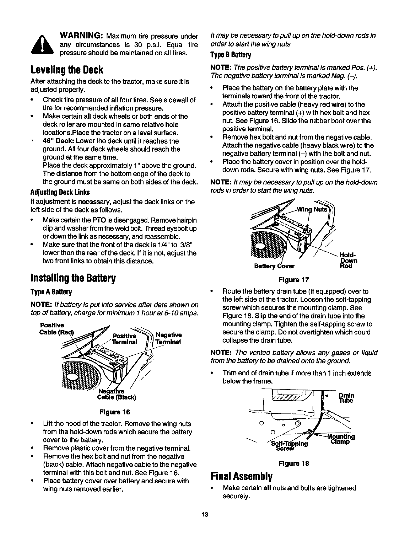
InstallingtheBattery
Type ABattery
NOTE: If battery is put into service after date shown on
top of battery, charge for minimum I hour at 6-10 amp&
Positive
Cable Neget ve
Terminal
(Black)
Flgure 16
• Liftthe hood of the tractor. Remove the wing nuts
from the hold-down rods which secure the battery
cover to the battery.
• Remove plastic cover from the negative terminal.
• Remove the hex bolt and nutfrom the negative
(black) cable. Attach negative cable to the negative
terminal with this bolt and nut. See Figure 16.
• Place battery cover over battery and secure with
wing nuts removed earlier.
It may be necessary to pull up on the hold-down rods in
order to start the wing nuts
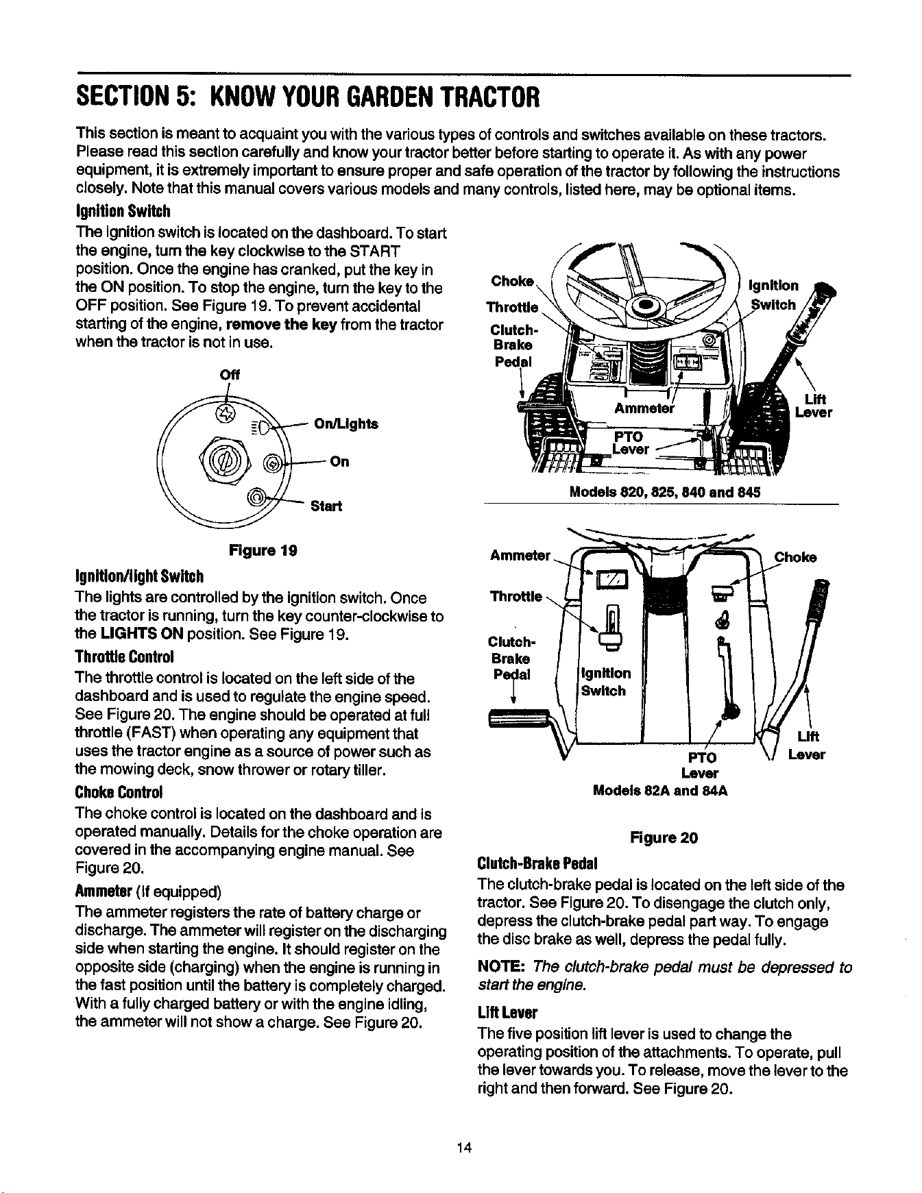
TypeB Battery
NOTE: The positive battery terminal is marked Pos. (+).
The negative battery terminal is marked Neg. (-).
• Place the battery on the battery plate with the
terminals toward the front of the tractor.
• Attach the positive cable (heavy red wire) to the
positive battery terminal (+) with hax bolt and hax
nut. See Figure 16. Slide the rubber boot over the
positive terminal.
• Remove hex bolt and nut from the negative cable.
Attach the negative cable (heavy black wire) to the
negative battery terminal (-) with the bolt and nut.
• Place the battery cover in position over the hold-
down rods. Secure with wing nuts, See Figure 17.
NOTE:/t may be necessary to pull up on the hold-down
rods in order to start the wingnuts.
_. Hold-
Down
Battery Rod
Figure 17
Route the battery drain tube (if equipped) over to
the left side of the tractor. Loosen the self-tapping
screw which secures the mounting clamp. See
Figure 18. Slip the end of the drain tube into the
mounting clamp. Tighten the self-tapping screw to
secure the clamp. Do not overtighten which could
collapse the drain tube.
NOTE: The vented battery allows any gases or liquid
from the battery to be drained onto the ground.
• Trim end of drain tube if more than 1 inch extends
below the frame.
O
Figure 18
FinalAssembly
• Make certain all nuts and bolts are tightened
securely.
13
SECTION5: KNOWYOURGARDENTRACTOR
This section is meant to acquaint you with the various types ofcontrols and switches available on these tractors.
Please read this section carefully and know your tractor better before startingto operate it. As with any power
equipment, it isextremely important to ensure proper and safe operation of the tractor by following the instructions
closely. Note that this manual covers various models and many controls, listed here, may be optional items.
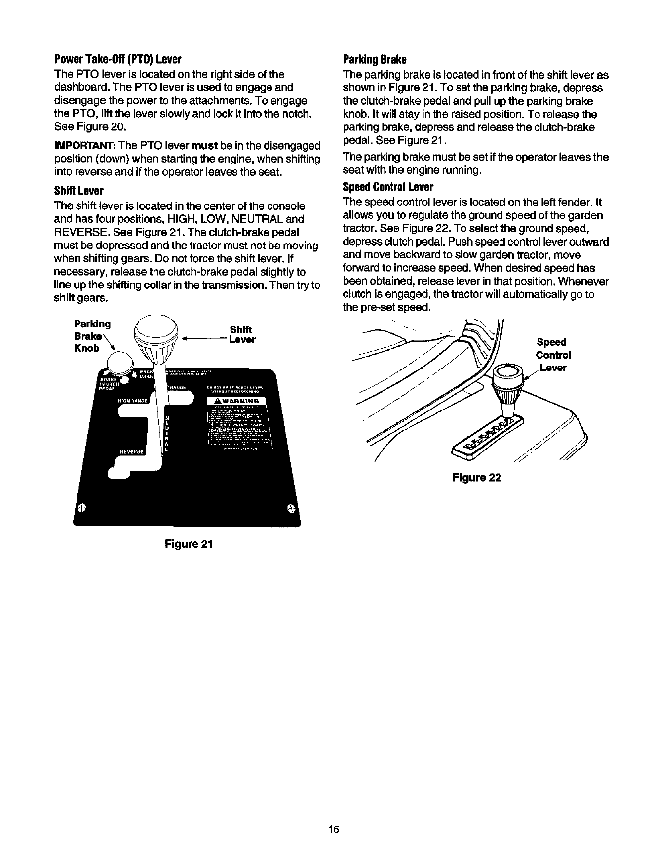
IgnitionSwitch
The ignition switch is located on the dashboard. To start
the engine, turn the key clockwise to the START
position. Once the engine has cranked, putthe key in
the ON position.To stop the engine, turn the key to the Choke\ Ignition
OFF position. See Figure 19. To prevent accidental Throttle
\
starting of the engine, remove the key from the tractor Clutch-
when the tractor is not in use. Brake
Off
Lever
Models 820, 825, 840 and 845
Figure 19
Ignitlon/ligM Switch
The lights are controlled by the ignition switch. Once
the tractor is running, turn the key counter-clockwise to
the LIGHTS ON position. See Figure 19.
Throttle Control
The throttle control is located on the leftside of the
dashboard and isused to regulate the engine speed.
See Figure 20. The engine should be operated at full
throttle (FAST) when operating any equipment that
uses the tractor engine as a source of power such as
the mowing deck, snow thrower or rotary tiller.
ChokeControl
The choke control is located on the dashboard and is
operated manually. Details for the choke operation are
covered in the accompanying engine manual. See
Figure 20.
Ammeter(If equipped)
The ammeter registers the rate of battery charge or
discharge. The ammeter willregister on the discharging
side when starting the engine. It should register on the
opposite side (charging) when the engine is running in
the fast position untilthe battery is completely charged.
With a fully charged battery or with the engine idling,
the ammeter will not show a charge. See Figure 20.
Ammeter Choke
Clutch-
Brake
Pe_al
Fro
Lever
Models 82A and 84A
Lift
Lever
Figure 20
Clutch-BrakePedal
The clutch-brake pedal is located on the left side of the
tractor. See Figure 20. To disengage the clutch only,
depress the clutch-brake pedal part way. To engage
the disc brake as well, depress the pedal fully.
NOTE: The clutch-brake pedal must be depressed to
start the engine.
Lift Lever
The five position lift lever is used to change the
operating positionof the attachments. To operate, pull
the lever towards you. To release, move the lever to the
right and then forward. See Figure 20.
14
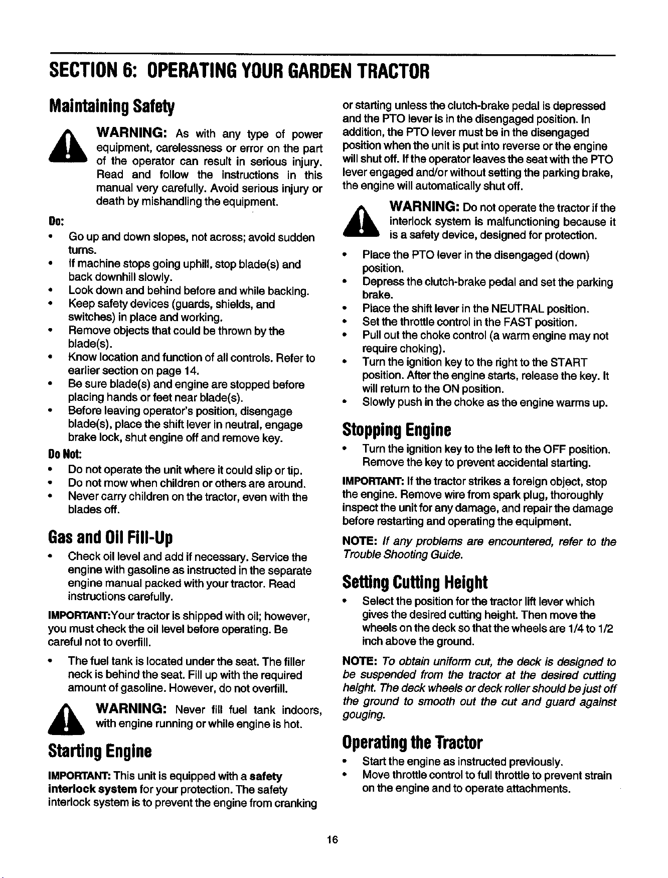
PowerTake-off (PTO) Lever
The FTO lever is located on the rightside of the
dashboard. The PTO lever is used to engage and
disengage the power to the attachments. To engage
the PTO, lift the lever slowly and lock it into the notch.
See Figure 20.
IMPORTANT: The PTO lever must be in the disengaged
position (down) when starting the engine, when shifting
into reverse and ifthe operator leaves the seat.
Shift Lever
The shift lever is located in the center of the console
and has four positions, HIGH, LOW, NEUTRAL and
REVERSE. See Figure 21. The clutch-brake pedal
must be depressed and the tractor must not be moving
when shifting gears. Do not force the shift lever. If
necessary, release the clutch-brake pedal slightly to
line up the shifting collar in the transmission. Then try to
shift gears.
Parldng Shift
Lever
Knob
ParkingBrake
The parking brake is located in front of the shift lever as
shown in Figure 21. To set the parking brake, depress
the clutch-brake pedal and pull up the parking brake
knob. It will stay in the raised position. To release the
parking brake, depress and release the clutch-brake
pedal. See Figure 21.
The parking brake must be set if the operator leaves the
seat with the engine running.
SpeedControlLever
The speed control lever is located on the left fender. It
allows you to regulate the ground speed of the garden
tractor. See Figure 22. To select the ground speed,
depress clutch pedal. Push speed control lever outward
and move backward to slow garden tractor, move
forward to increase speed. When desired speed has
been obtained, release lever in that position. Whenever
clutch is engaged, the tractor will automatically go to
the pre-set speed.
Speed
Control
Lever
Figure 22
Figure 21
15
SECTION6: OPERATINGYOURGARDENTRACTOR
MaintainingSafety
WARNING: As with any type of power
equipment, carelessness or error on the part
of the operator can result in serious injury.
Read and follow the instructions in this
manual very carefully. Avoid serious injury or
death by mishandling the equipment.
0o:
• Go up and down slopes, not across; avoid sudden
turns.
• If machine stops going uphill, stop blade(s) and
back downhill slowly.
• Look down and behind before and while backing.
• Keep safety devices (guards, shields, and
switches) in place and working.
• Remove objects that could be thrown by the
blade(s).
• Know location and function of all controls. Refer to
earlier section on page 14.
• Be sure blade(s) and engine are stopped before
placing hands or feet near blade(s).
• Before leaving operator's position, disengage
blade(s), place the shift lever in neutral, engage
brake lock, shut engine offand remove key.
DoNot:
• Do not operate the unit where it could slip or tip.
• Do not mow when children or others are around.
• Never carry children on the tractor, even with the
blades off.
Gasand011Fill-Up
• Check oil level and add if necessary. Service the
engine with gasoline as instructed inthe separate
engine manual packed with your tractor. Read
instructionscarefully.
IMPORTANT:Your tractor is shipped with oil;however,
you must check the oil level before operating. Be
careful not to overfill.
• The fuel tank is located under the seat. The filler
neck is behind the seat. Fill up with the required
amount of gasoline. However, do not overfill.
,_ WARNING; Never fill fuel tank indoors,
with engine running or while engine ishot.
StartingEngine
IMPORTANT: This unit is equipped with a safety
interlock system for your protection. The safety
interlock system isto prevent the engine from cranking
or starting unless the clutch-brake pedal is depressed
and the PTO lever is inthe disengaged position. In
addition, the Pro lever must be in the disengaged
position when the unit is put into reverse orthe engine
willshut off. If the operator loaves the seat with the PTO
lever engaged and/or without setting the parking brake,
the engine will automatically shut off.
WARNING: Do not operate the tractor if the
interlock system is malfunctioning because it
is a safety device, designed for protection.
• Place the PTO lever in the disengaged (down)
position.
• Depress the clutch-brake pedal and set the parking
brake.
• Place the shift lever in the NEUTRAL position.
• Set the throttle control inthe FAST position.
• Pull out the choke control (a warm engine may not
require choking).
• Turn the ignition key to the right to the START
position. After the engine starts, release the key. It
willreturn tothe ON position.
• Slowly push inthe choke as the engine warms up.
StoppingEngine
• Turn the ignition key to the left to the OFF position.
Remove the key to prevent accidental starting.
IMPORTANT: If the tractor strikes a foreign object, stop
the engine. Remove wire from spark plug, thoroughly
inspect the unitfor any damage, and repair the damage
before restarting and operating the equipment.
NOTE: If any problems are encountered, refer to the
Trouble Shooting Guide.
SettingCuffingHeight
• Select the positionfor the tractor liftlever which
gives the desired cutting height. Then move the
wheels on the deck so that the wheels are 1/4 to 1/2
inchabove the ground.
NOTE: To obtain uniform cut, the deck is designed to
be suspended from the tractor at the desired cutting
height. The deck wheels or deck roller should be just off
the ground to smooth out the cut and guard against
gouging.
OperatingtheTractor
• Start the engine as instructed previously.
• Move throttle control to full throttle to prevent strain
on the engine and to operate attachments.
16

Placethe shift lever in one of the two forward
positions (LOW or HIGH), or in REVERSE. Place
the speed control lever in desired position. Use first
speed position when operating the tractor for the
first time.
,_ WARNING: Look to the rear of the tractor
and check for obstructions before backing up.
• Release the parking brake by depressing the
clutch-brake pedal. Release clutch-brake pedal
slowly to put unit into motion.
• The tractor is brought to a stop by depressing the
clutch-brake pedal.
• The cutting blades (or other attachment) may be
engaged while the tractor is moving or standing still.
DO NOT engage the cutting blades abruptly as the
sudden belt tension on the pulley may cause the
engine to stall.
,_ WARNING: Keep feet and hands away
from the discharge opening, the blades or any
part of the deck.
NOTE: When operating the unit initially, there will be
little difference between the highest two speeds until
after the belts have seated themselves into the pulleys
during the break-in period. Be certain to change oil in
the crankcase after the first 5 hours of operation.
• Be sure that the lawn is clear of stones, sticks, wire,
or other objects which could damage tractor or
engine. For best results, do not mow when lawn is
too wet.
WARNING: Before leaving the operator's
position for any reason, disengage the
blades, place the shift lever in neutral, engage
the parking brake, shut engine offand remove
the key.
• When stopping the unit to empty a grass bag, etc.,
follow the instructionsabove. This procedure will
also eliminate "browning" the grass, which is
caused by hot exhaust gases from a running
engine.
If unit stalls with speed control in sixth or seventh
speed, or if unit will not operate with speed control lever
in first or second speed position, proceed as follows.
• Place shift lever in NEUTRAL.
• Restart engine.
• Place speed control lever in highest speed position.
• Release clutch-brake pedal fully.
• Depress clutch-brake pedal.
• Place speed control lever in desired position.
• Place shift lever in one of the forward positions
(HIGH or LOW) or REVERSE, and follow normal
operating procedures.
High-LowTransmissionRanges
HIGH range position is for normal load conditions, such
as mowing or transporting.
LOW range position is for situations which require more
torque when the tractor is used under high load
conditions, such as tilling,snow removal or hauling
heavy loads.
GrassCollector
GRASS COLLECTOR Model OEM-190-083 is
available as optional equipment for tractors with 46"
mowing decks.
,_ WARNING: The mower should not be
operated without the entire grass catcher or
chute deflector in place.
NOTE: Under normal usage, grass bag material is
subject to wear, and should be checked periodically. Be
sure to use only factory authorized replacement bag.
17
SECTION7: MAKINGADJUSTMENTS
,_ WARNING: Disconnect the spark plug
wire(s) and ground against the engine before
performing any adjustments, repairs or
maintenance,
LevelingtheDeck
The sides of the deck should be the same distance from
the ground. The front of the deck should be 1/4" to 3/8"
lower than the rear of the deck. If adjustment is
required, refer to "Leveling the Deck" in Assembly
Instructions.
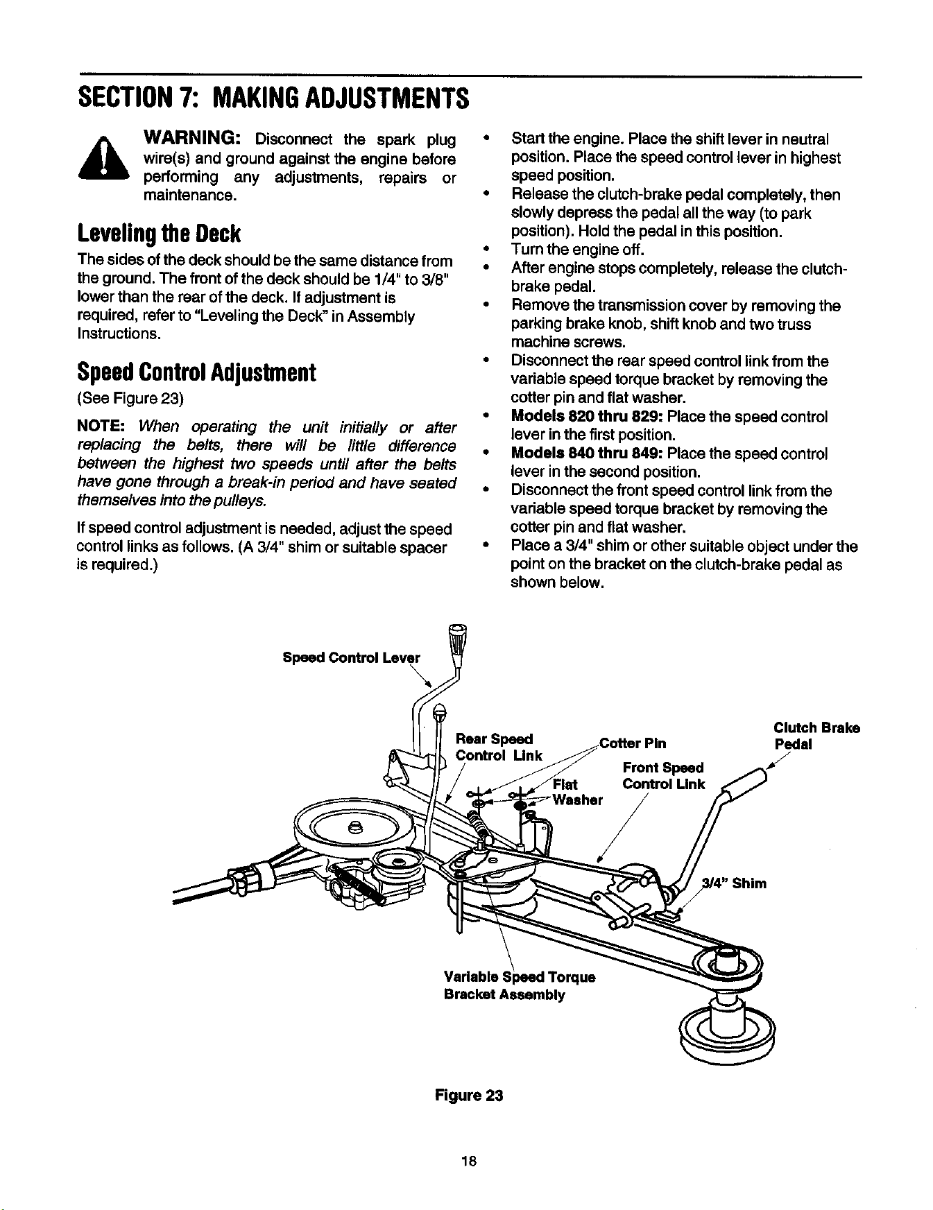
SpeedControlAdjustment
(See Figure 23)
NOTE: When operating the unit initially or after
replacing the belts, there will be little difference
between the highest two speeds until after the belts
have gone through a break-in period and have seated
themselves into the pulleys.
Ifspeed control adjustment isneeded, adjust the speed
control links as follows. (A 3/4" shim or suitable spacer
is required.)
• Start the engine. Place the shift lever in neutral
position. Place the speed control lever in highest
speed position.
• Release the clutch-brake pedal completely, then
slowly depress the pedal all the way (to park
position). Hold the pedal in this position.
• Turn the engine off.
• After engine stops completely, release the clutch-
brake pedal.
• Remove the transmission cover by removing the
parking brake knob, shift knob and two truss
machine screws.
• Disconnect the rear speed control linkfrom the
variable speed torque bracket by removing the
cotter pin and flat washer.
• Models 820 thru 829: Place the speed control
lever inthe first position.
• Models 840 thru 849: Place the speed control
lever inthe second position.
• Disconnect the front speed control linkfrom the
variable speed torque bracket by removing the
cotter pin and flat washer.
• Place a 3/4" shim or other suitable object under the
point on the bracket on the clutch-brake pedal as
shown below.
SpeedContmlLeve_
Rear Speed
Control Unk
Clutch Brake
Cotter Pin Pedal
Front Speed
Control Link
Shim
Variable
Bracket Assembly
Figure 23
18
• Thread the front speed control link in or out of the
ferrule until the hole in the link lines up with the pin
on the variable speed torque bracket. Secure with
the flat washer and cotter pin removed earlier.
• Push the rear speed control linkbackward using
light pressure, and hold it inthis position as you
thread it into or out of the ferrule until the hole in the
link lines up with the pin on the variable speed
torque bracket.
• Models 820 thru 829 Only: Turn the link three
more times (making itlonger).
• Move the speed control lever toward the right so
'the _,o_ein the rear speed oo_tro__inkf_t_ever the
pin on the variable speed torque bracket. Secure
with the flat washer and cotter pin removed eadier.
• Remove the 3/4" shim from beneath the bracket on
the clutch-brake pedal.
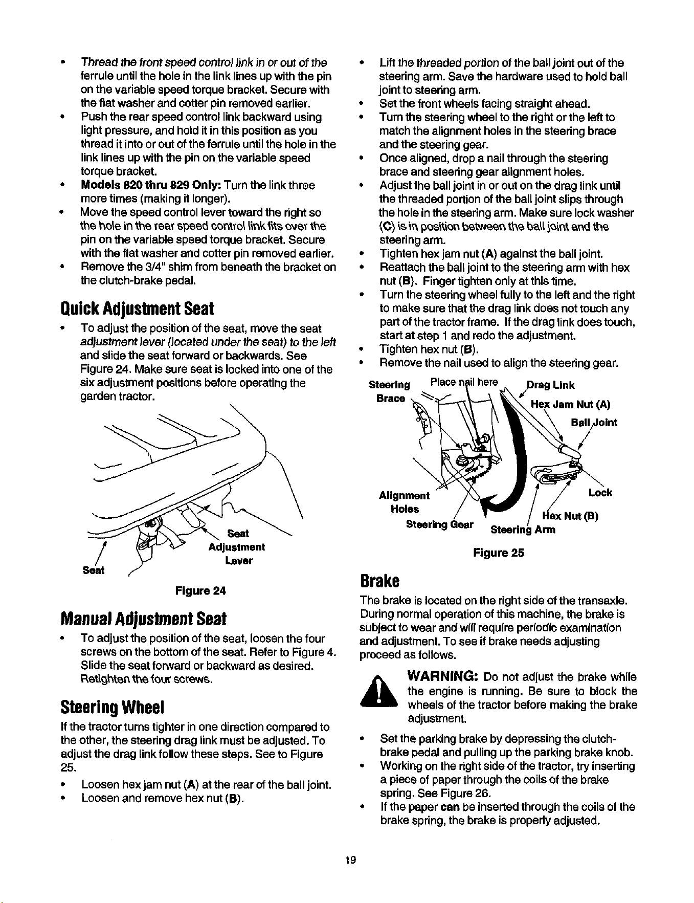
QuickAdjustmentSeat
• To adjust the position of the seat, move the seat
adjustment lever (located under the seat} to the left
and slide the seat forward or backwards. See
Figure 24. Make sure seat is locked into one of the
six adjustment positions before operating the
garden tractor.
• Lift the threaded portion of the ball joint out of the
steering arm. Save the hardware used to hold ball
joint to steering arm.
• Set the front wheels facing straight ahead.
• Turn the steering wheel to the right or the left to
match the alignment holes in the steedng brace
and the steering gear.
• Once aligned, drop a nail through the steering
brace and steering gear alignment holes.
• Adjust the ball joint in or out on the drag link until
the threaded portion of the ball joint slips through
the hole in the steering arm. Make sure lock washer
_C_is _ p_s'_t'_n_t_eer_ tt,,e ba_ i_ir_t _r_ the.
steering arm.
• Tighten hex jam nut (A) against the ball joint.
• Reattach the ball joint to the steering arm with hex
nut (B), Finger tighten only at this time.
• Turn the steering wheel fully to the left and the right
to make sure that the drag link does not touch any
part ofthe tractor frame. If the drag link does touch,
start at step 1 and redo the adjustment.
• Tighten hex nut (B).
• Remove the nail used to align the steering gear.
Steering Place 7 here Link
Brace
HexJam Nut (A)
Seat
Adjustment
Lever
Seat
Figure 24
ManualAdjustmentSeat
• To adjust the position of the seat, loosen the four
screws on the bottom of the seat. Refer to Figure 4.
Slide the seat forward or backward as desired.
Ret'_o,_hte_tt\e four screws.
SteeringWheel
Ifthe tractor turnstighter inone direction compared to
the other, the steering drag linkmust be adjusted. To
adjust the drag link follow these steps. See to Figure
25.
• Loosen hex jam nut (A) at the rear of the ball joint.
• Loosen and remove hex nut (B).
\
Alignment Lock
Holes
t (e)
Steering Gear Arm
Figure 25
Brake
The brake is located on the right side of the transaxle.
During normal operation of this machine, the brake is
subject to wear and will require periodic examination
and adjustment. To see if brake needs adjusting
proceed as follows.
WARNING: Do not adjust the brake while
the engine is running. Be sure to block the
wheels of the tractor before making the brake
adjustment.
• Set the parking brake by depressing the clutch-
brake pedal and pulling up the parking brake knob.
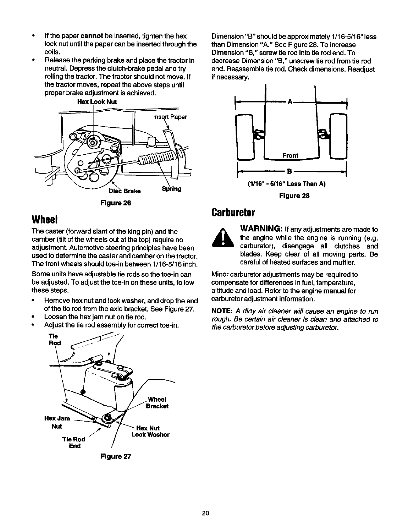
• Working on the rightside of the tractor, try inserting
a piece of paper through the coils of the brake
spring, See Figure 26.
• If the paper can be inserted through the coilsof the
brake spring, the brake is properly adjusted.
19
If the paper cannot be inserted, tighten the hex
lock nut until the paper can be inserted through the
coils.
Release the parking brake and place the tractor in
neutral. Depress the clutch-brake pedal and try
rollingthe tractor. The tractor should not move. If
the tractor moves, repeat the above steps until
proper brake adjustment is achieved.
He]( Lock Nut
Figure 26
Wheel
The caster (forward slant of the king pin) and the
camber (tilt ofthe wheels out at the top) require no
adjustment. Automotive steering principles have been
used to determine the caster and camber on the tractor.
The front wheels should toe-in between 1/16-5/16 inch.
Some units have adjustable tie rods so the toe-in can
be adjusted. To adjust the toe-in on these units, follow
these steps.
• Remove hex nut and lock washer, and drop the end
of the tie rod from the axle bracket. See Figure 27.
• Loosen the hex jam nut on tie rod.
• Adjust the tie rodassembly for correct toe-in.
Tie
Rod
Dimension "B" should be approximately 1/16-5/16" less
than Dimension "A." See Figure 28. To increase
Dimension "B," screw tie rod into tie rod end. To
decrease Dimension "B," unscrew tie rod from tie rod
end. Reassemble tie rod. Check dimensions. Readjust
if necessary.
__ Front
(1116" - 5/16" Less Than A)
Figure 28
I
Carburetor
WARNING: Ifany adjustments are made to
the engine while the engine is running (e.g.
carburetor), disengage all clutches and
blades. Keep clear of all moving parts. Be
careful of heated surfaces and muffler.
Minor carburetor adjustments may be required to
compensate for differences in fuel, temperature,
altitude and load. Refer to the engine manual for
carburetor adjustment information.
NOTE: A dirty air cleaner will cause an engine to run
rough. Be certain air cleaner is clean and attached to
the carburetor before adjusting carburetor.
Wheel
Hex Jam
Nut
Tie Rod
End
Lock Washer
Figure 27
20
SECTION8: MAINTAININGYOURGARDENTRACTOR
WARNING= Disconnect the spark plug
wire(s) and ground against the engine before
performing any adjustments, repairs or
maintenance.
Lubrication
SteeringGears
Lubricate teeth of steering gears with automotive multi-
purpose grease after every 25 lr_u(s o__e._*;_ _
once a season. Refer to Figure 25.
SteeringShaft
Lubricate steering shaft at least once a season with
lightoil.
Transaxln
The transaxJe is lubricated and sealed at the factory
and does not require checking. If disassembled for any
reason, lubricate with 32 oz. of Shell Darina grease,
part number 737-0148 (16 oz. tube).
Linkage
Once a season lubricate all the pivot points on the
clutch, brake and lift linkage with SAE 30 engine oil.
Wheels
The front wheels may be provided with grease fittings.
Lubricate at least once a season with automotive multi-
purpose _rease.
PIvM Points
Lubdcate all pivot pointswith light oil at least once a
season.
BallJoints
The ball joints and drag link ends are permanently
lubricated and do not need any further lubrication.
BladeSpindles
The blade spindles on the cutting deck are permanently
lubricated and do not need any further lubrication.
EngineMaintenance
Refer tothe engine manual for maintenance instructions.
A list of general recommendations is given below.
• Maintain engine oil as instructed in the engine
manual. Read and follow instruCtions carefully.
• Service air cleaner every 25 hours under normal
conditions. Clean every few hours under extremely
dusty condition. To service the air cleaner, refer to
the separate engine manual packed with your unit.
• The spark plugs should be cleaned and the gap
reset once a season. Spark plug replacement is
recommended at the start of each mowing season;
check engine manual for correct plug type and gap
specifications.
CuttingBlades
,_ WARNING." Protect hands by using heavy
gloves or a rag to grasp the cutting blades.
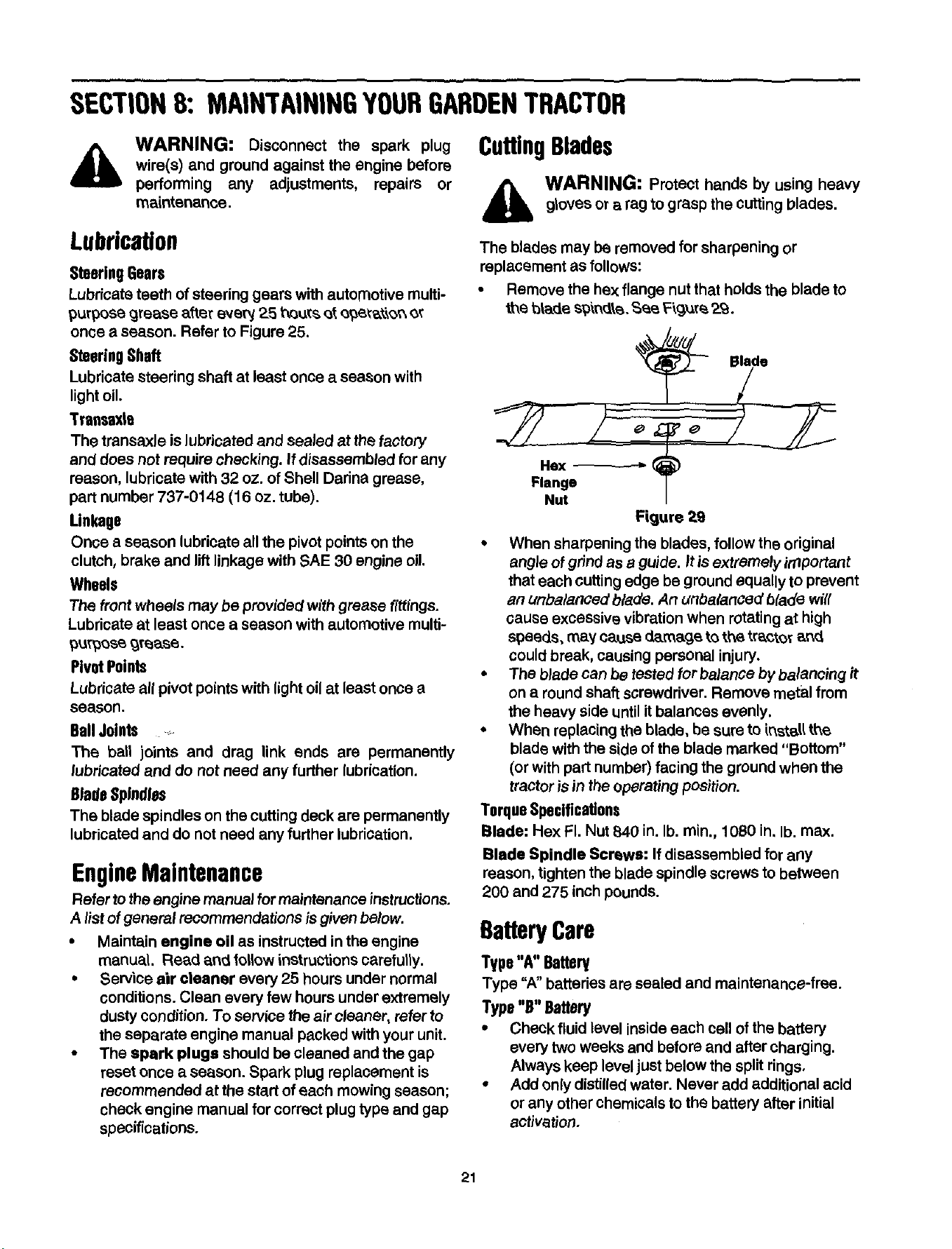
The blades may be removed for sharpening or
replacement as follows:
• Remove the hex flange nut that holds the blade to
the t_tades_'_r_e. Sea F\g_re 2o_.
÷
Hex
Flange
Nut
Figure 29
• When sharpening the blades, follow the original
angle of grind as a guide. It is extremely, important
that each cutting edge be ground equally to prevent
an unbalanced blade. An unbalanced blade wig
cause excessive vibration when rotating at high
speeds, may cause damage to the tractor ar_
could break, causing personal injury.
• The blade can be tested for balance by,balancing if
on a round shaft screwdriver. Remove metal from
the heavy side untilit balances evenly.
• When replacing the blade, be sure to instal(the
blade with the side of the blade marked "Bottom"
(or with part number) facing the ground when the
tractoris in theoperating position.
TorqueSpecifications
Blade: Hex FI. Nut B40 in. lb. rain., 1080 in, lb. max.
Blade Spindle Screws: If disassembled for anY
reason, tighten the blade spindle screws to between
200 and 275 inch pounds.
BatteryCare
Type "A °'Battery
Type "A" batteries are sealed and maintenance-free.
Type "B" Battery
• Check fluid level inside each cell of the battery
every two weeks and before and after charging.
Always keep level just below the split rings,
• Add only distilled water. Never add additional acid
or any other chemicals to the battery after initial
activation.
21
NOTE: ff you have operated the tractor for a long
period, check the fluid level of the battery as it can
overheat and lose fluid.
Chargingthe Battery
The engine isequipped with an alternator which
charges battery when tractor is operated. Under normal
conditions, the battery onlyneeds to be charged b_fore,
during and after oft-season storage. Follow the
instructions under "Off-Season Storage."
• To charge the battery: Battery P/N 725-1705D---
Charge at 2-3 amps for one hour. Battery P/N 725-
1707D, 725-0453G, 725-1750, and 725-1706--
Charge at Gam_s for one hour.
Rem0vlng/ Re-Installingthe Battery
WARNING: When removing or installing
the battery, follow these instructions to
prevent the screwdriver from shorting against
the frame.
• Removing the Battery: Disconnect negative cable
first, then positive cable.
• Installing the Battery: Connect positive cable first,
then negative cable.
Jump Starting
• First, connect end of one jumper cable to the
positive terminal of the good battery, then the other
end tothe positive terminal of the dead battery.
• Connect the other jumper cable to the negative
terminal ofthe good battery, then to the frame of
the unit with the dead battery.
WARNING: Failure to use this procedure
could cause sparking, and the gas in either
battery could explode.
Cleanthe Battery
Clean the battery by removing it from the unit end
washing with a baking soda and water solution. If
necessary, scrape the battery terminals with a wire
brush to remove deposits. Coat terminals and exposed
wiring with grease or petroleum jelly to prevent
corrosion.
Battery Failures
Some common causes for battery failure are: incorrect
initial activation, lack of water, adding chemicals other
than water after initial activation, undercharging,
overcharging, corroded conneCtiOns,freezing. These
failures do not constitute warranty work.
Tires
• Maximum tire pressure under any cimumstances is
30 p.s.i. Equal tire pressure should be maintained
on all tires. Check tire sidewalls for proper inflation.
• When installing a tire to the rim, be certain rim is
(;lean and free of rust. Lubricate both the tire and
rim generously. Never inflate to over 30 p.s.J,to
seat beads.
WARNING: Excessive pressure (over 30
p,s.i.) when seating beads may cause tire/rirn
assembly to burst with force sufficient to
cause serious injury.
CleaningEngineandDeck
• Any fuel or oil spilled on the machine should be
wiped off promptly. Grass, leaves, and other dirt
must not be allowed to accumulate around the
cooling fins of the engine or on any part of the
mechirJe. Clean the underside ofthe deck after
each mowing.
FuelFilter
Your unit is equipped with a replaceable in-line fuel
filter. Replace filter whenever contamination or
disco|oration is noticed. Order replacement fitter
through an authorized engine service dealer.
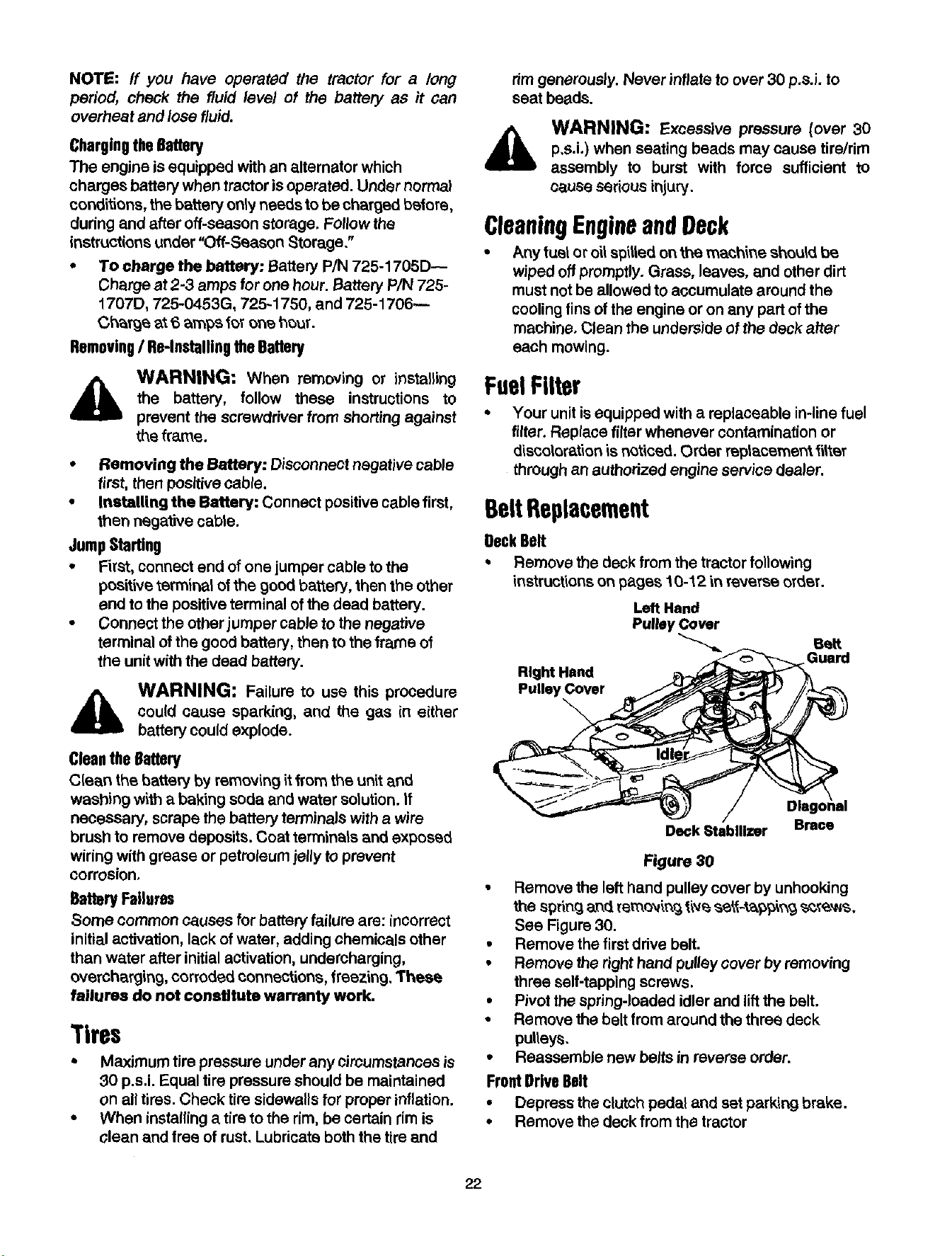
BeltReplacement
BackBelt
• Remove the deck from the tractor following
instructionson pages 10-12 in reverse order.
Left Hand
Pulley Cover
Belt
Guard
Rlght Hand
Pulley Cover
\
Dlago\nal
Deck Stabilizer Brace
Figure 30
• Remove the lefthand pulley cover by unhooking
the spring and removing ti,4_s_1_,_gj _,_,Ns,
See Figure 30.
• Remove the first drive belt.
• Remove the dght hand pulley cover by removing
three self-tapping screws.
• Pivot the spring-loaded idler and lift the belt.
• Remove the belt from around the three deck
pulleys.
• Reassemble new belts in reverse order.
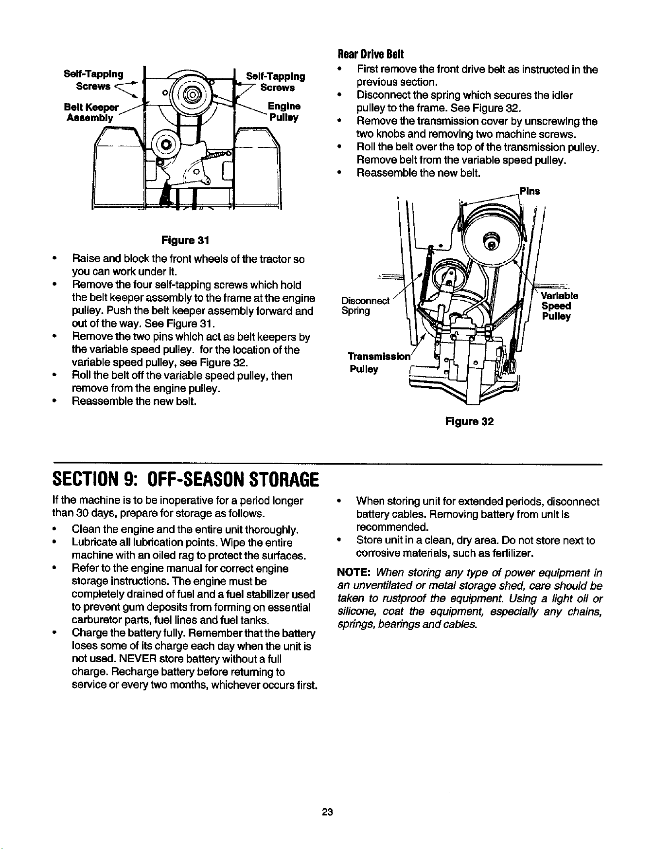
FrontDrive Belt
• Depress the clutch pedal and set parking brake.
• Removethe deck fromthe tractor
22
Self-Tapping Self-Tapping
Screws
Belt Keeper
Assembly
RearDriveBelt
• First remove the front drive belt as instructed in the
previous section.
• Disconnect the spring which secures the idler
pulley to the frame. See Figure 32.
• Remove the transmission cover by unscrewing the
two knobs and removing two machine screws.
• Roll the belt over the top of the transmission pulley.
Remove belt from the variable speed pulley.
• Reassemble the new belt.
Pins
Figure 31
• Raise and block the front wheels ofthe tractor so
you can work under it.
• Remove the four self-tapping screws which hold
the belt keeper assembly to the frame at the engine
pulley. Push the belt keeper assembly forward and
out of the way. See Figure 31.
• Remove the two pins which act as belt keepers by
the variable speed pulley, for the location of the
variable speed pulley, see Figure 32.
• Roll the belt offthe variable speed pulley, then
remove from the engine pulley.
• Reassemble the new belt.
@
Spring Speed
Pulley
Pulley
Figure 32
SECTION9: OFF-SEASONSTORAGE
If the machine isto be inoperative for a period longer
than 30 days, prepare for storage as follows.
• Clean the engine and the entire unitthoroughly.
• Lubricate all lubrication points. Wipe the entire
machine with an oiled rag to protect the surfaces.
• Refer to the engine manual for correct engine
storage instructions. The engine must be
completely drained of fuel and a fuel stabilizer used
to prevent gum deposits from forming on essential
carburetor parts, fuel lines and fuel tanks.
• Charge the battery fully. Remember that the battery
loses some of its charge each day when the unit is
not used. NEVER store battery without a full
charge. Recharge battery before returning to
service or every two months, whichever occurs first.
• When storing unit for extended periods, disconnect
battery cables. Removing battery from unit is
recommended.
• Store unit in a clean, dry area. Do not store next to
corrosive materials, such as fertilizer.
NOTE: When storing any type of power equipment in
an unventilated or metal storage shed, care should be
taken to rustproof the equipment. Using a light oil or
silicone, coat the equipment, especially any chains,
springs, bearings and cables.
23

SECTION10: OPTIONALEQUIPMENT
At the time of manufacture of tractor, the following optional equipment is available.
Description Model No.
Grass Collector For 46" Deck OEM-190-083
Mulching Kit For 46" Deck OEM-190-118
45" Two Stage Snow Thrower OEM-190-624
48" Dozer Blade 0EM-190-840
42" Rear Dozer Blade** OEM-190-804
Agdculutral Traction Tires OEM-190-865
Tire Chains--23 x 9.5 OEM-190-964
100 lb. Wheel Weights OEM-190-784
Front Bumper Kit OEM-190-226
Sleeve Hitch Kit 0EM-190-929
28" PTO Driven Rear Mounted Tiller OEM-190-757
38" 8 HP Rear Mounted Tiller OEM-190-756
Electric Lift Kit OEM-190-749
10" Moldboard Plow** OEM-190-978
Single Disc Harrow** OEM-190-980
Row Crop Cultivator** OEM-190-984
Gang Reel (Set of three)* 45-0195
36" Lawn Sweeper* 45-0222
Heavy Duty Lawn Roller* 45-0179
Heavy Duty Dump Cart* 45-0171
Tine De-Thatcher* 45-0186
* Availiable through your local dealer or from Agri-Fab Inc., 303 W. Raymond Street, Sullivan, Illinois 61951
* *Sleeve Hitch Required (OEM-190-929)
24

SECTION11:TROUBLESHOOTING
Corrective Action
Trouble
Enginewillnot 1.
crank
2.
3.
4.
5.
Enginecranks 1.
butwillnotstart
2.
3.
4.
5.
6.
Enginesmokes 1.
2.
3.
Excessive 1.
vibration
2.
Mowerwillnot 1.
dischargegrass 2.
or leavesuncut 3.
strips 4.
Possible Cause(s)
Safetyswitchbuttonnot
depressed.
Battery installed incorrectly.
Batteryisdeadorweak.
Blownfuseorcircuitbreaker
Engine ground wire loose.
Throttle or choke not in
starting position
No fuel to the carburetor
Fuel line or in-line fuel filter
plugged
Spark pluglead
disconnected
Faulty sparkplug
Dirtyaircleaner
Engineoilhasbeen
overfilled.
Dipsticknotseatedand/or
broken.
Enginelosescrankcase
vacuum.
Looseboltorpart,
Bent or damaged blade.
Engine speed low.
Speed selection.
Cutting height set too low.
Blades short or dull.
1. There are two switches in the starting cimuit of your unit: the clutch
pedal switch and the deck liftlever switch. Make certain the actuator
isfully depressing the buttons on each switch.
2. The battery must be installed with negative terminal attached to black
ground wire. Negative terminal is identified at the post by "NEG", "N" !
or"-". The positive terminal, identified by "POS', "P" or "+", must be
attached to the big red wire which goes to the solenoid, All batteries
are to be fully charged before installing. Refer to "Quick Start" battery
guide that came with the operator's manual.
3. Check fluid level in battery. If fluid is low, fill to just below split rings
with water. Charge with 6 AMP charger untilthe battery is fully
charged.
4. Refer to the illustrated parts listfor fuse box location. Replace fuse
with automotive type fuse. Fuses seldom fail without a reason. The
problem must be corrected. Check for loose connections in the fuse
holder. Replace fuse holder it necessary. A dead short may be inthe
cranking or charging circuit where the insulation may have rubbed
through and exposed the bare wire. Replace the wire or repair with
electrician's tape ifthe wire strands have not been damaged.
Note: Look for a wire pinched between body panels, burned by the
exhaust pipe or muffler or rubbed against a moving part.
i 5. Engine should have a black ground wire runningfrom engine to frame
or mounting bolt.
1. Check operator's manual for correct position for throttle control and
choke forstarting.
2. Gasoline tank empty. Filltank.
3. Remove and clean fuel line. Replace filter if necessary.
4. Connectlead.Holdsparkplugleadawayfromengineblockabout 1/
8".Crank engine,There shouldbe a spark. If not, haveengine
repairedat authorizedengineservicedealer.
5. To test,removesparkplug.Attachsparkplugleadtosparkplug,
Groundthe sparkplugbodyagainsttheengineblock.Crankthe
engine.The sparkplugshouldfire at the electrode.Replaceif if does
not.
J6. Refertotheenginemanual.
1. Checkoillevel,
2. Re-insert dipstick properly. Replace defective part if needed.
3. Enginebreatherdefective.Replacefollowingenginemanual.
1. Stop engineimmediately.Checkallpulleys,bladeedapters, keysand
boltsfortightnessandspindledamage.Tightenor replaceany
damagedparts.
2. Replacebladefollowing instructioninthismanual,
1. Throttlemustbe set atfullthrottle,
2. Uselowergroundspeed.
3. Raisedeck.
4. Sharpenor replaceblades(uncutstrip problemonly).
25

_OURI!OTE_
Date Comments
L_
26

Date
YOURNOTES
Comments
27
MANUFACTURER'S LIMITED WARRANTY FOR:
YARD
The limited warranty set forth below is given by MTD
PRODUCTS INC ("MTD") withrespect tOnew merchandise
purchasedand used in the UnitedStates, its possessions
andterritories.
MTD warrants this productagainst defeCts'in matedal and
workmanshipfor a periodof two (2) yearscommencingon
the dateof originalpurchaseandwill,at itsoption,repairor
replace, free of charge, any part found to be defectivein
materialor workmanship.This limitedwarranty shall only
applyif this producthas been operatedand maintained in
accordance with the Operator's Manual furnished with the
product,and has not been subjectto misuse, abuse, com-
memial use, neglect, accident, improper maintenance,
alteration, vandalism,theft,fire, water or damage because
of other perilor naturaldisaster.Damage resultingfrom the
installationor use of any accessory or attachment not
approvedby MTD ProductsInc. for use withthe product(s)
covered by this manual will void your warranty as to any
resulting damages.
Normal wear parts or componentsthereofare subjectto
separateterms as follows:Allnormalwear part or compo-
nentfailures willbe covered onthe productfor a podod of
90 days regardlessof cause. After90 days, butwithinthe
two year period, normalwear part failureswill be covered
ONLY iF causedby defects in materialor workmanshipof
OTHER componentparts. Normalwear partsand compo-
nents include,but are not limitedto, belts, blades, blade
adapters, grass bags, rider deck wheels, seats, snow
thrower skid shoes, shave plates and tires. Batteriesare
coveredbya 90-daylimitedreplacementwarranty.
HOW TO OBTAIN SERVICE: Warrantyserviceisavailable,
WITH PROOF OF PURCHASE THROUGH YOUR LOCAL
AUTHORIZED SERVICE DEALER. To locatethe dealer in
your area, please checkfor a _istingin the "YellowPages or
contactthe CustomerService Departmentof MTD PROD-
UCTS INC bycalling 1-800-800-7310 orwritingto nO. Box
368022, Cleveland,Ohio44136-9722.
This limited warranty does not provide coverage In the
following eases:
a.The engineor component partsthereof. These items
carrya separatemanufacturer's warranty,Pleaserefer
to the applicable manufacturer's warrantyon these
items.
b. Logsplitter pumps,valvesand cylindershavea sepa-
rateor_syear warranty.
c. Routine maintenance items such as lubricants, filters,
blade sharpening and tune-ups, or adjustments such
as brake adjuslrcents, crutch ad)ustments or deck
adjustments; and normal deterioration of the exterior
finish due to use or exposure.
d. MTD does not extend any warranty for products sold
or exported outside of the United States of America,
its possessions and territories, except those sold
through MTD's authorized channels of export distribu-
tion.
No implied warra_y, Inoluding any Implied warranty of
merchantability or fitness for a particular purpoae,
applies after the applicable period of ax_preeawritten
warranty above as to the parts as identified. No other
express warranty or guaranty, whether written or oral,
except as mentioned above, given by any person or
entity, Including a dealer or retailer, with raepect to any
product shall bind MTD. During the period of the War-
ranty,the exclusive remedy Is repair or replacement of
the product as eat forth above, (Some states do not
allowlimitationson how longan impliedwarrantylasts,so
theabove limitationmay notapplyto you.)
The provisions as _mt forth In this Warranty provide the
sole and exclusive remedy arising from the sales. MTD
shall not be liable for incidental or consequential loss
or damages Including, without limitation, expenses
Incurred for substitute or replacement lawn care ear.
vlcse, for transportation or for related expanses, or for
rental expenses to temporarily replace a warranted
product. (Some states do not allow the exclusion or limita-
tion of incidental or consequential damages, so the above
exclusion or _ireitation may not apply 1oyou.)
In no eventshall recoveryof any kind be greater thanthe
amountof the purchasepdceofthe productsold.Alteration
of the salary features of the product shallvo'_dt_is War-
ranty.Youassumethe riskand liabilityfor loss,damage, or
injuryto you and yourpropertyand/or to othersand their
propertyadsingoutof the use or misuseor inabilityto use
theproduct.
Thislimitedwarrantyshall notextendto anyone otherthan
the originalpurchaser,original lessee or the person for
whomit was pumhasedas a gift.
How State Law Relates to this Warranty: This limited
warrantygivesyou speoifialegal rights,and you mayalso
haveotherrightswhichvary from state tostate.