Loading ...
Loading ...
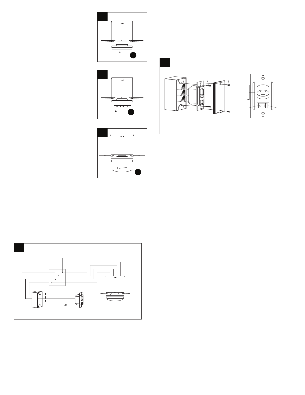
8. Remove 1 screw from motor plate on
underside of motor and partially loosen
the other 2 screws.
Connect blue wire from motor assembly
(A) to black wire from the LED light kit (F).
Connect white wire from motor assembly
(A) to white wire from LED light kit (F).
Make sure molex connections snap
together completely.
9. Gently push up on glass shade (G) and
turn to the RIGHT (clockwise) until it slides
completely into place
NOTE: Pull down VERY GENTLY on
glass shade (G) to make sure that it is
secure.
***The black wire, white wire and blue wire between ceiling outlet box
and wall outlet box are conductor cables.
*** If your wall outlet box has a ground wire (green or bare copper),
connect the yellow/ green ground wire from wall switch to it with a
wire nut. Otherwise connect the yellow/ green ground wire from wall
switch to one of the screws from the wall outlet box.
*** After the connections have been made, the wires from fan should
be pushed up carefully into the ceiling outlet box.
WARNING: Be sure no bare wire or wire strands are visible after
making connection. Place green and white connections on opposite
side of box from the black and blue (if applicable) connections.
10. Fan wire connection:
A. Connect blue wire from fan to blue wire from ceiling outlet box.
B. Connect black wire from fan to white wire from ceiling outlet box.
C. Connect white wire from fan to white wire (neutral) from ceiling
outlet box.
D. Connect green ground wires from downrod and bracket to
ground wire (green or bare copper) from ceiling outlet box.
Wall switch connection:
A. Connect black wire (live) from ceiling outlet box to black /white
wire from wall switch.
B. Connect white wire from ceiling outlet box to black wire from wall
switch.
C. Connect blue wire from ceiling outlet box to blue wire from wall
switch.
11. Wall Switch Installation:
Carefully tuck the wire connections from wall switch inside wall outlet
box. Secure the wall switch with two wall switch screws provided.
Attach the wall switch cover over the wall switch and secure with two
wall switch cover screws provided.
Warning: Hook up in" series only". Do not connect the live and neutral
wires of the electric circuit to the wall switch- damage to the switch and
possible re could occur.
Operation:
The fan 3-speed control is used to set the fan speeds as follows:
0= Turns the fan off
H= High Speed
M= Medium Speed
L= Low Speed
"OFF-ON" light Button:Turn on/off the light
Forward and reverse direction function:
This ceiling fan is equipped with a Reverse Switch for downward or
upward air-ow.
NOTE: Do not use the Reverse Switch when the fan blades are in
motion.
Forward function
On this setting, the fan will turn counterclockwise to create a cooling
effect. Use this function during warmer weather to circulate the hot air
away from your living space.
Reverse function
On this setting, the fan will turn clockwise. Use this function during
cooler weather to re-circulate warm air.
7. Remove 1 screw from motor plate on
underside of motor and partially loosen
the other 2 screws.
Align slotted holes in tter plate (C) with
loosened screws in motor plate, allowing
molex to come through centre hole
in tter plate (C). Twist tter plate to lock.
Re-insert screw that was previously
removed and securely tighten all 3 screws
with a crosshead screwdriver.
7
8
9
Ground Wire (Green/Bare Copper)
Neutral Wire (White)
Green
White
Black
Blue
Live Wire (Black)
Blue Wire
Yellow/Green
Ground Wire
Black Wire
Black/White Wire
Wall Switch
Fan
Wall Outlet Box
Ceiling Outlet Box
10
11
Wall Switch
Wall Switch Screw
Wall Outlet
Box
Wall Switch
Cover
Wall Switch
Cover Screw
*
L
M
H
0
ONOFF
OFF
M
H
0
F
G
C
Loading ...