
OPERATOR'S MANUAL
7-1/4 in. CIRCULAR SAWWITH LASER GUIDE
DOUBLE INSULATED
Model No.
315.108620
WARNING: Toreduce_herbk of injury,
the user must read and understand the
operator's manual before using this product.
Customer Help Line: 1-800-932-3188
Sears, Roebuck and Co., 3333 Beverly Rd., Hoffman Estates, IL 60179 USA
Visit the Craftsmanweb page: wwwosears.com/craftsman
983000-B17
9-05 (REV:01)
Save this manual for future reference

m Warranty ............................................................................................................................................................................. 2
m Introduction ..................................................................................................................................................................... 2
[] General Safety Rules .................................................................................................................................................... 3-4
u Specific Safety Rules ..................................................................................................................................................... 4-5
[] Symbols ........................................................................................................................................................................ 6-7
[] Electrical .......................................................................................................................................................................... 8
B Features ........................................................................................................................................................................ 9-10
[] Assembly .................................................................................................................................................................. 10-12
[] Operation .................................................................................................................................................................. 13-20
[] Adjustments ................................................................................................................................................................... 21
m Maintenance .................................................................................................................................................................... 22
nl Exploded V_ewand Parts List.........................................................................................................................................................................................23-24
[] Parts OrderinglService ........................................................................................................................................ Back Page
ONE-YEAR FULL WARRANTY ON CRAFTSMAN TOOL
If this Craftsman tool fails to give complete satisfaction within one year fromdate of purchase, RETURN IT TO ANY
SEARS STORE OR PARTS AND REPAIR CENTER OR OTHER CRAFTSMAN OUTLET IN THE UNITED STATES FOR
FREE REPAIR.
If this Craftsman tool is used for commercial or rental purposes, this warranty applies for only90 days from the date of
purchase,
This warranty gives you specific regal rights, and you may a|so have other rights whtch vary from state to state,
Sears, Roebuck and Co., Dept. 817WA, Hoffman Estates, IL 6017g
This tool has many features for making its use more pleasant and enjoyable. Safety, performance, and dependability
have been given top priority in the design of this product making it easy to maintain and operate.
A
WARNING! Read and understandall instrue-
'dons.Failureto follow aJlinstructionslistedbelow,
mayresultInelectricshock,fire and/orserious
personalinjury_
SAVE THESE INSTRUCTIONS
WORK AREA
[] Keepyourwork area clean andwell lit. Cluttered
benchesand dark areasinviteaccidents_
B Do not operatepowertoolsin explosive atmo-
spheres,suchas In thepresenceofflammableliq-
uids,gases,or dust. Powertoolscreatesparkswhich
may ignitethedust or fumes.
[] Keep bystanders,children,andvisitorsawaywhile
operatinga powertoot.Distractions cancauseyouto
losecontrol,
ELECTRICAL SAFETY
[] Double insulated tools are equtpped with a polar-
ized plug (one blade is wider than the other), This
plug will fit in a polarized outlet only one way. If the
plug does not fit fully in the outlet, reverse the plug,
If it still does not fit, contact a qualified electrician
to install a polarized outlet. Do not change the plug
in anyway. Double Insulation [] eliminatesthe need
for the three-wire grounded power cord and grounded
power supply system.
= Avoid body contact with grounded surfaces such as
pipes, radiators, ranges and refrigerators. There isan
increased risk of electric shock ifyour body is grounded°
II Don't expose power tools to rain or wet conditions.
Water entering a power tool will increase the riskof
electricshock,
[] Do not abuse the cord. Never use the cord to carry
the tools or pull the plug from an outlet. Keep cord
away from heat, oil, sharp edges or moving parts.
Replace damaged cords immediately. Damaged
cords increase the risk of eiectdc shock.
[] When operating a power tool outside, use an outdoor
extension cord marked "W-A" or WV".These cords
are ratedfor outdoor use and reduce the risk of electric
shock.
PERSONAL SAFETY
[] Stayalert,watch what youare doingandusecom-
mon sensewhen operatinga powertool Do not
usetootwhiletired or underthe influenceof drugs,
alcohol,or medication.A momentof inattentionwhile
operdtingpowertools mmyresult inseriouspersonai
injury.
[] Dressproperly.Donot wear looseclothingor
jewelry.Containlonghair. Keep yourhair,clothing,
and glovesaway frommovingparts.Looseclothes,
jewelry,orlong hair canbe caught in movingparts.
• Avoidaccidentalstarting. BesureswitchIsoff
before plugging In. Carrying tools with yourfinger on
the switch or plugging in tools that have the switch on
invitesaccidents.
• Remove adjusting keys or wrenches before turning
the too! on. A wrench or a keythat is left attached to a
rotating par_of the tool may result in personal lnjury.
I Do not overreach. Keep proper footing and balance
at all times, Proper footing and balance enables better
control of the too_in unexpectedmtualicnso
• Use safety equipment. Always wear eye protection.
Dust mask, non-skid safety shoes, hard hat, or hearing
protection must be used for appropriate conditions
• Do not wear loose clothing or Jewelry. Contain long
hair. Loose clothes, jewelry, or long haircan be drawn
into air vents.
[] Do not use on a ladder or unstable support. Stable
footing on a solid surface enables better control of the
tool in unexpected siluations.
TOOL USE AND CARE
B Use clamps or other practical way to secure and
support the workpiece to a stable platform. Holding
the work by hand or against your body is unstableand
may lead to loss of control
[] Do not force tool, Use the correct tool for your ap-
plication. The correct tool will do the job better and
safer at the rate for whJch it is designed.
u Do not use tool if switch does not turn it on or off.
Any t_l that cannot be controlled w(th the switch is
dangerous and must be repaired,
[] Disconnect the plug from power source before
making any adjustrnentsj changing accessories,
or storing the tool. Such preventive safety measures
reduce the risk of starting the too! accidentally.
[] Store Idle tools out of reach of children and other
untrained persons. Tools are dangerous In the hands
of untrained users.
[] Maintain tools with care. Keep cutting tools sharp
and clean. Property maintained tows with sharpcut-
ting edges are tess likely to bind and are easier to
control.
[] Check for misalignment or binding of moving parts,
breakage of parts, and any other condition that
may affect the tool's operation. If damaged, have
the tool serviced before using, Many accidents are
caused by poody maintainedtools,
[] Use cnhJaccessories that are recommended by the
manufacturer for your model. Accessories that may
be suitable for one toot, may become hazardous when
used on another tool
I Keep the tool and its handle dry, clean and free
from og and grease. Always use a clean cloth when
clBaning_ Never use brake fluids, gasoline, petroleum-
based products, or any strongsolvents to clean your
too!. Following this rule will reduce the risk of loss of
con_oland delefiorationoftheenclosureplastic,

SERVICE
[] Tool servicemustbe performedonlybyqualified
repairpersonnel.Serviceor maintenanceperformed
byunqualifiedpersonnelcouldresultina riskofinjury.
=' Whenservtc]ngatool, useonlyIdentical replace-
ment parts.Followinstructions in the Maintenance
sectionofthis manual.Useof unauthorizedpartsor
failuretofollow MaintenanceInstruct_onsmay createa
riskofelectricshockor injury,
I DANGER!Keep hands away from cutting area and
blade.Keepyour secondhandon auxiliaryhandleor
motorhousing.If bothhandsare holdingthesaw,they
cannot be cutby 1heblade°
• Keepyour bodypositionedto either side of the saw
blade, but not in line with the saw blade. Kickback
could causethe saw to jumpbackwards.(See"Causes
AndOperator Preventionof Kickback"later..)
[] Donot reacll underneaththe work. Theguardcannot
protectyou from the bladebelow thework,
==Checklowerguardforproperclosing beforeeachuse.
Donotoperatesawiflowerguarddoesnotmovefreely
andcloseinstanlJy.Nevercramporhethe lowerguard
intothe openposiUon.Ifsawisaccidentallydropped,
lowerguardmaybe bent. Raisethelowerguardwiththe
retractinghandleand makesureitmovesfreelyanddoes
not touch the blade or any otherpart, in all anglesand
depths of cut,
m Checktheoperationand cond'dlonef the lowerguard
spdng, If the guard andthe springarenot operating
properly,theymustbeservicedbeforeuse.Lowerguard
may operatesluggishly due to damaged parts,gummy
deposits, or abuitdupo_debris.
= Lowerguard shouldbe retracted manually onlyfor
specialcuts,suchas"Pocket Cuts"and =Compound
Cuts."Raiselowerguardbyretractinghandle.Assoon
as blade enters the material, lower guard must be
released.Forall othersawing,thelowerguardshould
operateautomatically.
m Alwaysobservethat the lowerguardis coveringthe
bladebeforeplacingsaw downon benchorfloor.An
unprotected, coastingblade wi!lcausethesaw to walk
backwards,cutting whateveris initspath. Be awareof
the time it takes for the bladeto stop after switch is
released
H NEVERholdpiece beingcut inyourhandsor across
your leg. tt is important to supportthework properly
to minimize bodyexposure,blade binding,or lossof
control
i Hold tool by insulated gripping surfaces when
performingan operationwhere the cutting tool may
contacthiddenwiring or itsowncord. Contactwitha
"live"wirewiilmakeexposedmetalpartsefthetool=live_
and shockthe operator.
[] Whenripping,always usea ripfenceer straight edge
guide.Thisimprovesthe accuracyofthe cutandreduces
thechancefor blade binding°
i Always use blades with correct size and shape
Idtamond vs. round) arbor holes. Blades that de
not match the mounting hardware of the saw wltl run
eccentrically, causing loss of contre£
! Never use damaged or incorrect blade washers
or bolts. The blade washers and belts were specially
des'_gnedforthe saw for optimum performanceand safety
of operation,
Causes and Operator Prevention of Kickback:
Kickback is a sudden reaction to a pinched, bound, or
misaligned saw blade, causing an uncentre{ied saw te lift
up and out of the workpiece toward operator.
When the blade ispinched orbound t{ghtJybythe keffclesing
down, the blade sta(Is and the motor reaction drives the unit
rapidly back toward the eperaton
If the blade becomes twisted or misatigned in the cut, the
teeth at the back edge of the blade can dig into the top
surface of the wood causing the blade to c{Imb out ef the
kerr and jump back toward the operator,,
Kickback isthe result ofteol misuse and/or incorrect operating
procedures or conditions andcan be avoided bytaking proper
precautions, as given below:
[] Maintain a firm grip with both hands on the saw and
position your body and _rm to allow ye_ to resist
kickback {orcee. Kickback forces can be centro{{ed by
the operator, if proper precautions are taken.
u When blade is binding, or when interrupting a cut
for any mason, release the trigger and hotd the saw
motionless in the material until the blade comes to a
complete stop. Never attempt to remove the saw from
the work or pull the saw backward while the blade is
in motion, or KICKBACK may occur. Investigate and
take corrective actions to eliminate the cause of blade
binding,
[] When restarting a saw in the workpiece, center the
saw blade in the kerf and check that saw teeth are
not engaged Into the material, tf saw blade is binding,
it may walk up or KICKBACK from the workpiece as the
saw isrestarted.
• St_pport large panels to minimize the risk o1blade
pinching and KICKBACK. Large panels tend to sag
under their own weight. Supports must be placed under
the panel on both sides, near the iine ofcut and near the
edge of the panel.
m Do not usedull or damaged blade, Unsharpenedor
improperlysetbladesproducenarrowkerfwhich causes
excessivetriton, bladebinding andK_CKBACKo
m Blade depth and bevel adjusting locking levers
mustbe tight and securebeforemakingcut. Ifblade
adjustmentshiftswhitecutting,itmaycausebinding and
KICKBACK.
m Useextra cauUonwhen making a "Pocket Cut"into
ex_stingwallsorotherblindareas.Theprotrudingblade
may cutobjectsthat cancauseKICKBACK.
It Knowyourpowertool.Readoperator'smanualcare-
fully. Learn its applications and limitations, as well
asthe specificpotential hazardsrelatedto this tool.
Followingthis rulewillreducetherisk of electric shock,
fire,orserious injury.
m Always wear safety glasses.Everyday eyeglasses
haveonlyimpact-resistantlenses;theyareNOTsafety
glasses.Following1hismlewill reducetherisk ofserious
personalinjury.
=t Protectyour lungs.Wear a face or dust mask if the
operation is dusty.FollowingthisrulewiflTeducethe
riskofseriouspersonalinjury.
m Protectyourhearing.Wear hearingprotectionduring
extendedperiodsof operation.Fo_ing '_hisrulewill
reducetheriskofseriouspersonalinjury.
i Inspecttoolcordspertodicallyand,if damaged, have
repairedat your nearest authorizedservice center.
Constantlystayawareofcordlocation.Following this
rulewillreducethe riskofelectricshockor fire.
Check damaged parts, Before further use of the
tool, a guard or other part that is damaged should
becarefullycheckedtodeterminethatitwilloperate
properlyandpederm its intendedfunction. Checkfor
alignmentof movingparts,bindingofmovingparts,
breakageof parts_mounting,andanyotherconditions
thatmayaffectitsoperation.Aguardorotherpartthat
isdamagedshouldbeproperlyrepairedor replaced
byanauthorizedservicecenter.Followingthisrulewill
reducetherisk ofshock, fire, or sedousInjury.
m Make sure your extension cord is in good condition,
When using an extension cord, be sure to use one
heavy enough to carry the current your product
will draw. A wire gage sLze(A.W.G.) of at least 12 is
recommended for an extension cord 50 feet or
tess in length, A cord exceeding 100 feet is not
recommended, tf in doubt, use the next heavier gage.
The smaller the gage number, the heavier the cord. An
undersized cord wiltcause a drop in line voltage resulting
in loss of power and overheating.
I Inspect for and remove all nails from lumber before
using this tool, Folio'wing this rule wilt reduce the risk of
seriouspersonal injury.
Laser Guide Warnings:
The laser guide radiation used in the Craftsman circularsaw
is Class Ilia with maximum 5mW and 650nm wavelengths,
These lasers do not normally present an optical hazard
although stadng at the beam may cause flash blindness.
m Avotd direct eye exposurewhen using the laser guide.
m The laser shall be used and maintained in accordance
with the manufacturer's Instructions.
! Never aim the beam at aperson or object other than the
workpiece.
m Always ensure the laser beam is a(med at a sturdy
workpiece without reflective surfaces, Shiny reflective
sheet metal or similar shiny materials are not suitable for
laseruse.
m NI repairs should be made by an authorized service
representativeor the laser manufacturer.
IE Save these instructions, Refer to them frequently and
usethem to Instruct others who may use this tool tfyou
loan someone this too_, loan them these instructions
also.
_1= WAFIN|NG: Somedust createdbypowersanding,sawing,grinding,drilling,and otherconstructionactivities
containschemicalsknown to causecancer,blrth defects orotherreproductiveharm.Some examplesofthese
chemicalsam:
=_ead_remlead-basedpaints,
* crystallinesfflcafrom bricks andcementand othermasonryproducts, and
Jarsenic andchTomiumfrom chemically-treated_Umb_ro
Your riskfrom these exposuresvaries,dependingon how often you do this type of work,Toreduceyour exposure
tothese chemicals:work inawell ventilatedarea,and work withapproved safetyequipment,such asthose dust
masks t'natarespeda]lydesignedtofilterout microscopicparticles.

Some ofthe following symbols may be used on this tool, Please study them and learn theirmeaning_ Proper interpreta-
tion of these symbols wlll allow you to operate the tool better and safer,
SYMBOL NAME DESIGNATION/EXPLANATION
V Volts Voltage
,11,,i,i
A Amperes Current
ii iii i IH
Hz Hertz Frequency (cycles per second)
i , iI I J ijllllllllll,lllllll,,lllllllllllll'l,lllll, ll'l'll ii i,
W Watt Power
rain Minutes Time
"k, Alternating Current Type of current
== Direct Current Type or a characteristic of current
no No Load Speed Rotational speed, at no load
iii i,IIIIIIH,II
[] CIass il Construction Double-insulated construction
.Jmin Per Minute Revolutions,strokes, surface speed, orblts etc. per minute
i
Wet Conditions Alert Do not expose to rain or use in damp locations.
To reduce the risk of Injury, user must read and understand
Read The Operator's Manual operator's manual before using this pmducto
i ii i i i ii i i iiiiiiiii
Q Protection Always wear safety goggles, safety glasses with side shields, or
Eye
a full face shield when operating this product.
i i iii H HHHHHH,H,H,HH'H', I I I
s,ietyA,e. Precautions.hat,ovo,vo
your safety.
Failure to keep your hands away from the blade wtll result in
No Hands Symbol serious personal injury°
No Hands Symbol Failure to keep your hands away from the blade will result in
serious personal inju_
, ,, ,,, ,, ,, .,,,,,,,,,,,,,,,,,,,,,,,,,,,
Failure to keep your hands away from the blade will result in
No Hands Symbol
serious personal injury°
IHII :::::::::::::::::::::::
No Hands Failure to keep your hands away from the blade will result in
Symbol
serious personal injury.
H ,,H H,HHHHH,,,,HHH
Hot Surface To reduce the risk of injuryor damage, avoid contact with
any hot surface.
6
Thefollowingsignalwordsandmeaningsareintendedtoexplainthelevelsofriskassociated with this
product.
SYMBOL
H
A
A
SIGNAL MEANING
DANGER: Indicates an imminently hazardous situation,which, if not avoided, will
result in death or serious injury.
Indicates a potentially hazardous situation, which, if not avoided, coWd
WARNING: result in death or serious injury.
A
CAUTION; Indicatesa potentiallyhazardoussituation,which,ifnotavoided,may
resultinminor or moderateinjury.
CAUTION: (WithoutSafetyAlertSymbol) Indicatesa situationthat may resultin
property damage,
SERVICE
Servicingrequiresextremecareandknowledge and
shouldbe performedonly bya qualifiedservicetech-
nician.Forservicewe suggestyou returnthe product to
yournearestAUTHORIZEDSERVICECENTERfor repair.
Whenservicing,useonlyidentical replacementparts.
•_ WARN|NG: Toavoidseriouspersonalinjvry,do not
attempt to usethls product untieyou readthoroughly
andunderstandcomp|etelythe operators manual
Savethis operator'smanualand reviewfrequentlyfor
continuing safe operationand instructingothers who
may usethisproduoto
_l_ll,WARNING:
The operation of any power tool can result in foreign objects being thrown intoyour eyes, which
can result in severe eye damage. Before beginr_ing power too! operation, ak_ays wear safety
goggles, safety giasses with side shields, or a full face shield when needed. We recommend Wide
Vision Safety Mask for use over eyeglasses or standard safety grasses with side shields.
Atways use eye protection which is marked to compfy with ANSI ZBT.1.
SAVE THESE INSTRUCTIONS

DOUBLE INSULATION
Doublelnsulatlon tsa concept tn safetytnelectricpower
tools,whicheliminatestheneed fortheusualthree-wire
grounded powercord_All exposedmetal parts are
isolatedfrom the internalmetalmotor componentswith
protecting insulation.Doubleinsulatedtools do notneed
to be grounded.
'_ WARNING: The doubleinsulatedsystemis
intendedto protect the userfromshock resulting
from a breakin the tool's internalinsulation,Observe
a{tnormalsafety precautionstoavoidelectdcat
shock,
NOTE:Servicingof a tool withdoubteinsulationrequires
extremecareand knowledgeof thesystemand should
be performedonly by a qualifiedservicetechnician. For
eervtce,we suggest youreturnthetool to your nearest
authorizedservicecenter for repair.Alwaysuse origina)
factory replacementpadswhenservicing.
ELECTRICAL CONNECTION
Thistool hasa precision-builtelectricmotorr It shouldbe
connectedto a powersupplythatis120 rolL% 60 Hz,
AC only{normalhouseholdcurrenl_.Donot operate
thistool on direct current (DC}.A substantialvoltage drop
wiltcausea tossof powerand themotor will overheat,if
yourtoot doesnot operatewhen pluggedinto an outlet,
double-check the powersupptyo
EXTENSION CORDS
When using a power tool at a considerable distance from
a power source, be sure to use an extension cord that has
the capacity to handle the current the tool will draw. An
undersized cord will cause a drop in tine voltage, resulting
in overheating and loss of power. Use the chart to deter-
mine the minimum wire size required in an extens(on cord°
Only round jacketed cords listed by Underwriter's Labora-
tories (UL) should be used,
When working outdoors with a tool, use an extension
cord that is designed for outside use. This type of cord is
designated with "WA" on the cord'sjacket.
Before using any extension cord, inspect it for toose or
exposed wires and cut or worn insulation.
0-2,0 2,1-3.4 3.5-5.0 5.1-7.0 7,1-12.0 12.t-16.0
Cord Length Wire Size (A,W.G.)
25' 16 16 16 t6 14 14
50' 16 t6 16 !4 14 12
IDOL 16 I6 14 12 10 --
•"UsedonfZga_. 20ampcir_ui!
NOTE:AWG=AmericanWireGaUge
WARNING: Keep the extension cord dear of the
working area, Posfttonthe cord so that It will not get
caught on lumber, tools or other obstruotiot_s while
you are working with a power toolo Failure to do so
can resuff inserious personal injury.
A
WARNING: Checkextensioncords before each
use,ff damagedreplaceimmediately.Neveruse tool
with a damagedcordsince touching the damaged
areacoutd causeetectricalshock resuttingin serious
injury.
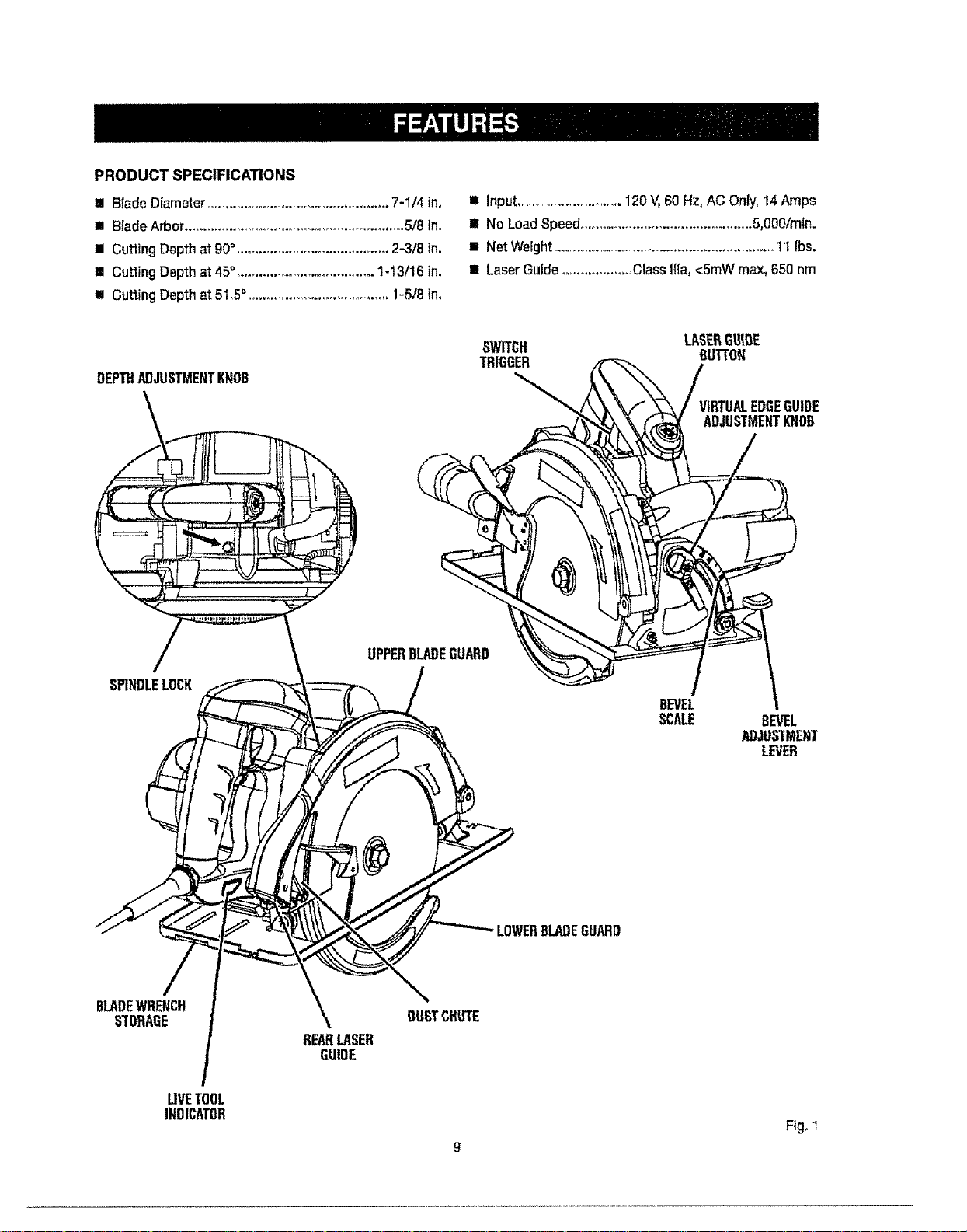
PRODUCT SPECIFICATIONS
I Blade Diameter .................................................... 7-1/4 ino
!1 Blade Arbor ............................................................ 5/8 in.
il Cutting Depth at 90°,.......................................... 2-3/8 in.
II Cuffing Depth at 45°,.................................... %13/16 in.
II Cutting Depth at 51,5°, ..................................... 1-5/8 in,
II Input............................120V,60 Hz,ACOnly, 14Amps
Ii NoLoad Speed..............................................5,0O0/min.
w NetWeight...........................................................11 Ibs.
I! LaserGuide...................ClassIlia, <5mWmax,850 nm
DEPTHADJUSTMENTKNOB
/
SPINDLELOCK
BLADEWRENCH
STORAGE
\
REARLASER
GU!OE
UPPERBLADEGUARD
BLADEGUARD
BEVEL
SCALE
VIRTUALEDGEGUIDE
ADJUSTMENTIOIOR
BEVEL
ADJUSTMEEIT
LEVER
LIVETOOL
INDICATOR
Fig° 1
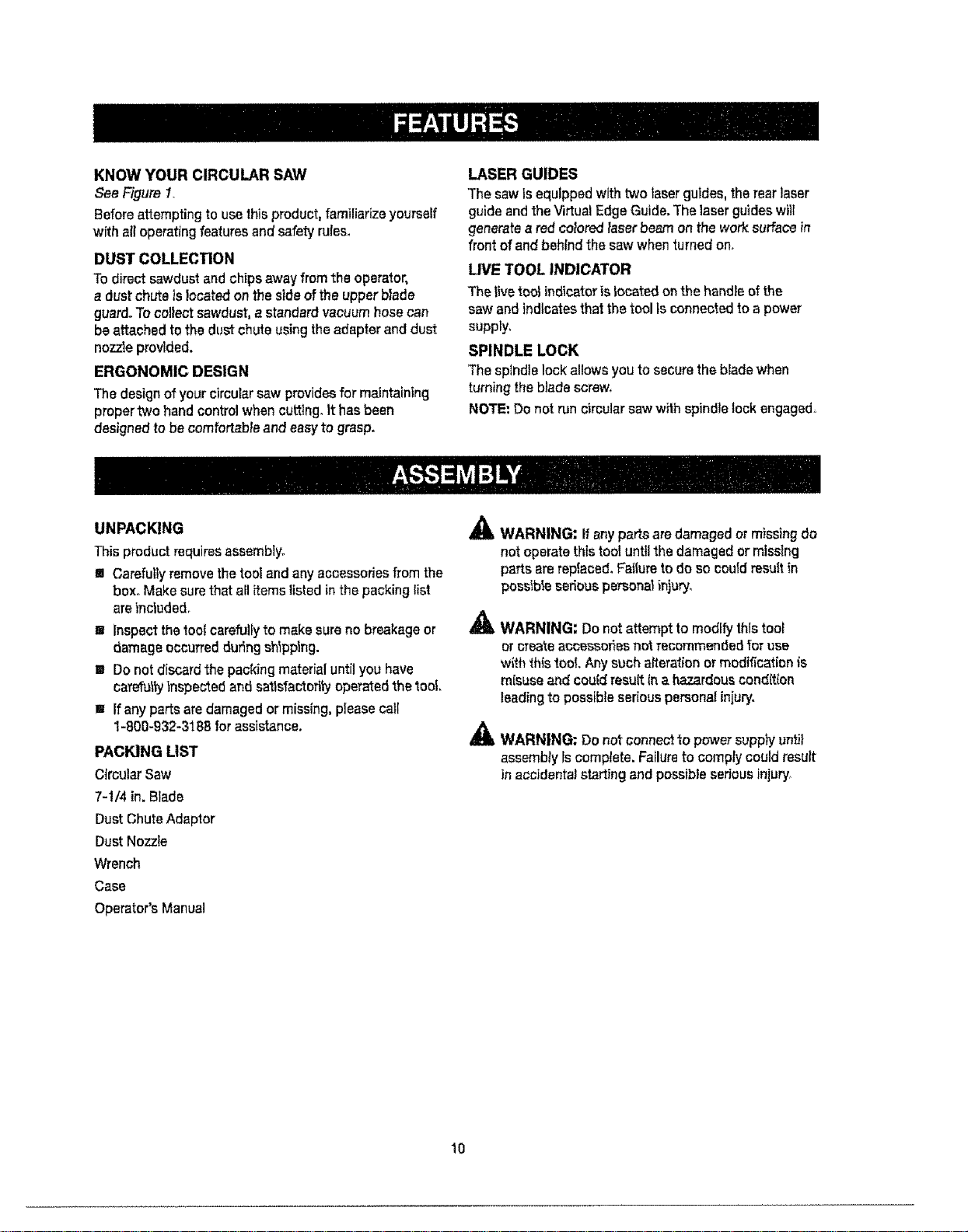
KNOW YOUR CIRCULAR SAW
See Figure 1.
Beforeattempting to usethisproduct,familiarizeyourself
with all operatingfeaturesand safetyruleso
DUST COLLECTION
Todirect sawdustand chips awayfrom the operator,
a dust chute is located on the sideof the upper blade
guard.To collectsawdust,a standard vacuumhosecan
be attached tothe dust chute usingtheadapterand dust
nozzleprovided.
ERGONOMIC DESIGN
Thedesignofyourcircular saw providesfor maintaining
proper two hand controlwhen cutting, It hasbeen
designedto be comfortable and easyto grasp,
LASER GUIDES
Thesaw Is equipped withtwo laserguides,the rearlaser
guideand theVirtual EdgeGuide.Thelaserguideswill
generatea redcoloredlaserbea'n onthe work surfacein
front of andbehind the saw whenturned on,
LIVE TOOL INDICATOR
Thelivetool indicatoris locatedon the handleofthe
saw and indicatesthat thetool Is connectedto a power
supply,
SPINDLE LOCK
The splndtelock allowsyouto securethe bladewhen
turningthe bladescrew,
NOTE:Donot run circularsawwithspindlelock engaged.
UNPACKING
This product requiresassemblyo
m Carefullyremovethe tool andany accessoriesfrom the
box. Makesurethat all itemslisted in thepacking list
arelnctuded_
w Inspectthe toolcarefullyto make sureno breakageor
damageoccurred duringshipping.
s Donot discardthe packing materialuntilyou have
carefut_tinspectedand satisfactorilyoperatedthe too!,
w ifany parts aredamagedor missing,pleasecall
1-800-932-318Bforassistance.
PACKING LIST
CircularSaw
7-!/4 in. Blade
DustChuteAdaptor
DustNozzle
Wrench
Case
Operator's Manual
A
A
WARNING: If anyparts aredamagedor missingdo
not operatethis tool untilthe damagedor missing
parts arerepfaced,Failursto do so couldresult in
possibteseriouspersonalinjury.
WARNING: Do not attempt to modify this tool
or create accessories not recommended for use
with this tool, Any such aPteralion or modification _s
misuse and could result In a hazardous cond(tton
leading to possible serious personat injury.
WARNING: Do notconnectto power supply until
assembly Iscomplete.Fatlureto complycouldresult
inaccidentalstartingand possible seriousinjury,
10
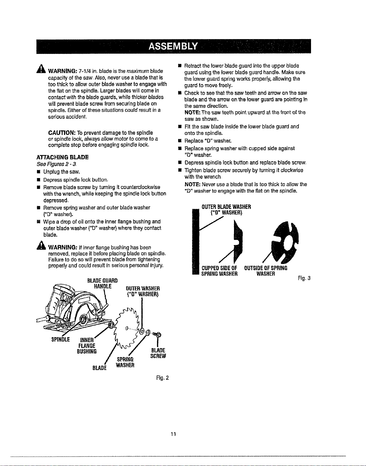
_l_ WARN|NG: 7-1/4 in. b|adeisthemaximumblade
capacityof thesaw.Also, neverusea blade that is
toothick to aliow outer bladewasherto engagewith
theflat onthe spindle. Largerbladeswiltcomein
contactwith the blade guards,whilethicker btadss
will preventblade screwfrom securingblade on
spindle. Eitherof thesesituations could resultin a
seriousaccident.
CAUTION: Toprevent damageto the spindle
or spindlelock, alwaysallowmotor to come to a
completestop beforeengagingspindlelock.
ATTACHING BLADE
See Rgures2 - 3.
= Unplugthe saw.
n Depressspindle lock button.
= Removeb[adescrew byturning itcounterolockwise
withthe wrench,while keepingthe spindlelock button
depressed,
m Removespringwasherand outarblade washer
("D"washer).
I=!Wipea drop of oil ontotheinnerflangebushingand
outerbladewasher("D"washer)wherethey contact
blade.
,_ WARN|NG: If innerflangebushinghasbeen
removed,replaceitbeforeplacingblade on spindle.
Failureto do so will preventblade from tightening
properlyand could resultIn seriouspersonalinjury.
BLADEGUARD
N_DLE OUIERWASHER
BUSHING / - /" BLADE
BLADE WASHER
Fig. 2
I Re&act the Zowerblade guard into the upper blade
guard using the lower blade guard hand(e_ Make sure
the tower guard spring works properly, allowing the
guard to move free_y,
m Check to see that the saw teeth and arrow on the saw
blade and the arrow on the lower guam are pot_ng tn
the same direction.
NOTE; The saw teeth point upward at the front of the
saw as shown.
m ;=Itthe saw blade Inside the lower blade guard and
onto the spindle,
E Replace =D" washer.
= Replace spring washer with cupped side against
"O" washer.
= Depress spindle lock button and replace blade SCraw,r
II Tighten blade screw securely by turning it clockwise
with the wrench.
NOTE; Never use a b)ade that is too thick to a!low the
"D" washer to engage with the fiat on the spindle.
OUTERBLADEWASHER
UPPEDSIDEOF OUTSIDEOFSPRING
PRINGWASHER WASHER
Fig, 3
tl
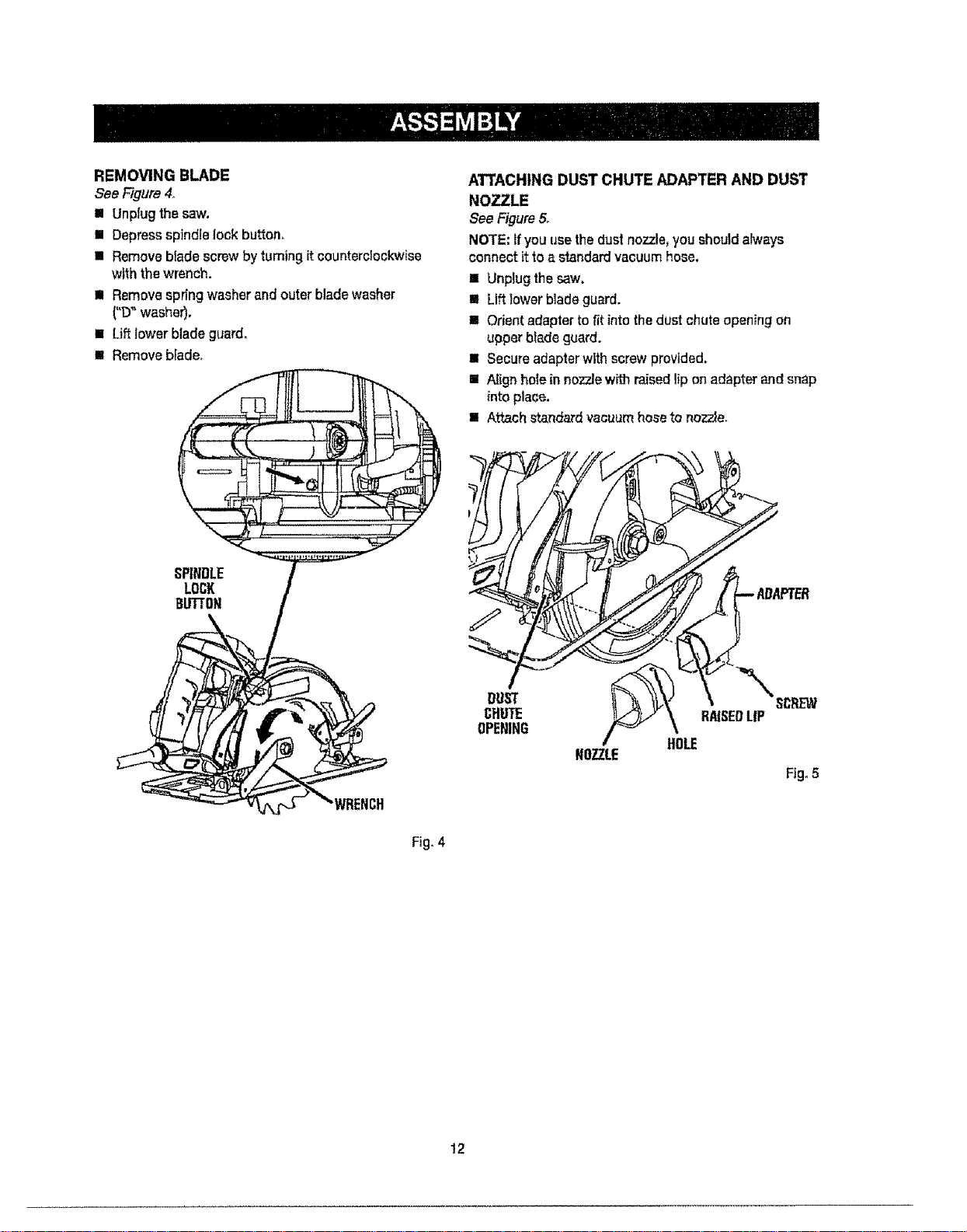
REMOVING BLADE
See Figure4_
m Unplugthesaw.
II Depressspindle lock button,
II Removeblade screw byturning itcounterclockwise
with the wrench.
n Removespring washerandouter bladewasher
("D_ washer),
= Lift lower blade guard.
III Removeblade_
ATTACHING DUST CHUTE ADAPTER AND DUST
NOZZLE
See Figure5,
NOTE:tf youusethedust nozzle,youshouldalways
connect it toa standardvacuumhose.
m Unplugthesaw.
= Lift lower bladeguard.
!1 Orientadapterto fit into the dust chute opening on
upperbladeguard.
m Secureadapterwlth screw provided.
m Alignhotein nozzlewi',_hraisedlip on adapterand snap
into place.
m Attachstandard vacuumhoseto nozzle.
NOZZLE
HOLE
Fig. 5
Fig, 4
12
,_& WARNING: Do notallowfamiliaritywithtools
to makeyou careless,Rememberthata careless
fraction ofa secondis sufficientto inflict serious
injury.
,_ WARNING: Alwayswearsafetygogglesor safety
glasseswithsideshieldswhenoperatingpower
tools. Failuretodo socouldresult in obiectsbeing
thrown intoyoureyes resultinginpossibleserious
injury,
_k WARNING; A)waysunplugthe tool whenchang-
ing operationsettings or whenthe tool is notin use,
Failureto unplugthe toolmayresuffinaccidental
startingand serfouspersonalinjury.
APPLICATIONS
Youmayusethistoolforthe purposeslisted below:
m CrossCutting/RipCutting
[] BevelCutting
[] PlungeCutting
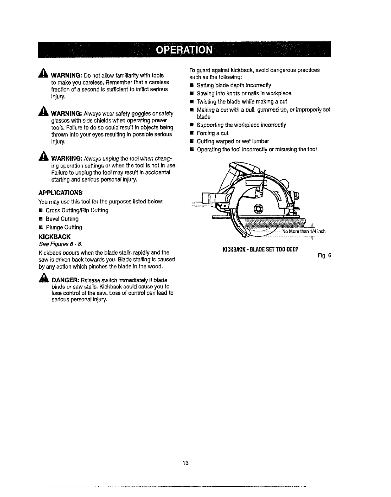
KICKBACK
See/figures 6 - 8o
Kickback occurs whenthe bladestallsrapidly andthe
saw is drivenback towardsyou, Bladestaitingis caused
by anyaction which pinchesthe bladeInthe wood°
_!_ DANGER: Releaseswitch immediatelyifblade
binds or saw stalls,Kickback could causeyou to
losecontrol of the saw.Loss of control canlead to
seriouspersonalinjury°
Toguard against kickback, avoid dangerous practices
such as the following:
m Setting blade depth incorrectly
• Sawing into knots or nails in workpiece
[] Twisting the blade while making a cut
• Making a cut with a dull, gummed up, or improperly s_
blada
• Supporting the workpiece incorrectly
• Forcing a cut
[] Cutting warped or wet lumber
[] Operating the tool Incorrectly or misusing the tool
NoMorethan1t4inch
KICKBACK- BLADESETTOODEEP
Fig,6
13
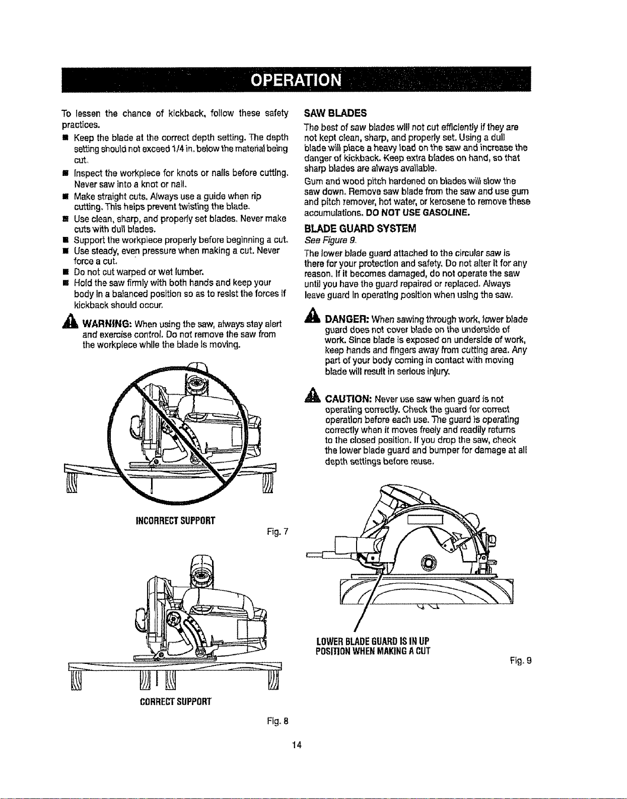
To lessen the chance of kickback, follow these safety
practices,
I Keep the blade at the correct depth setting. The depth
se_ng should not exceed 114in.below the material being
ct_
[] Inspect the workpleoe for knots or nails before cutting.
Never saw into a knot or nail.
[] Make straight cuts, Always use a guide when dp
cu'tting_This helps prevent twisting the blade,
Ill Use clean, sharp, and propedy set blades° Never make
cuts with dull blades.
[] Suppor_ the workpiece property before beginning a cut,
[] Use steady, even pressure when making a cut Never
force a cut,
[] Do not cut warped or wet lumben
I Hotd the saw firmly with both hands and keep your
body tn a balanced position so as to resist the forces If
kickback should ooouro
_I, WARNING'- When using the saw, atwaysstay alert
and exercise control Do not remove the saw from
the workpfece while the blade Is moving.
SAW BLADES
Thebest of saw bladeswill not cut efficientlyif theyare
notkept clean,sharp, and properlyset.Using a dull
blade wit1placoa heavyload onthe saw an6 increasethe
danger of kickback. Keep extrabladeson hand,so that
sharp bladesarealwaysavailable.
Gumandwood pitch hardenedon b_adeswill s_owthe
saw down. Removesaw bladefrom thesaw and usegum
and pitch remover,hotwater,or keroseneto removethese
accumulations. DONOT USEGASOLINE.
BLADE GUARD SYSTEM
See Figure9.
Thelowerblade guardattachedto the cimuJarsaw is
therefor yourprotection and safety.Donot alteritfor any
reason,if it becomesdamaged,do notoperatethe saw
untityouhavethe guard repairedorreplaced.Always
leaveguard Inoperatingposition whenusingthe saw.
_lb DANGER: Whensawingthroughwork, lowerblade
guarddo_snotcoverblade on theund_si6e of
work. Sincebladeis exposed onundersideofwork,
keephands and I_ngersaway fromcutting area.Any
part ofyourbody coming in contact withmoving
blade witl resulttnseriousinjury.
_!, CAUTION: Neveruse sawwhenguardis not
operatingcorrectly.Ch_k the g_ard for corral
operationbefore eachuse.The guard)soperating
correctlywhen itmovesfreatyand readilyreturns
to the closed position.If you drop thesaw,check
the lower blade guardand bumper fordamageat all
depths_ttingsbeforereu_.
INCORRECTSUPPORT
Fig. 7
CORRECTSUPPORT
Fig.8
/
LOWERBLADEGUARDISINUP
PDSI!lONWHENMAKINGACUT
Fig.g
14

STARTING/STOPPING THE SAW
See Figure 10,
Tostart thesam Depressthe switch trigger.
Ah_aysletthe b_adereachf,j_)speed,then gu)dethe saw
intotheworkp]ece.
_1_ WARNING: Theb)adecomingin contact w_ththe
workp]ese beforeIt reachesfull speedcould cause
the saw to "kickback" towardsyou resultingin
serious personalinjury.
Tostop the saw: Release the switch trigger.
NOTE: Allow the blade to come to a complete stop before
removing saw from workpleoe.
WARNING; Nways unplugthetoot whenchang-
[ngoperationsettings or whenthe tool is not inuse.
Failure1ounplugthe toolmay resultin accidentaK
starting and sedouspersona_Injury.
ADJUSTING BLADE DEPTH
See Figure11.,
Alwayskeepcorrectblade depthsalting. Thecorrect
blade depth settingfor al!cutsshoutd notexceed 1/4in,
belowthe matefia!being cut.Morebtadedepthwilt
increasethechance of kickbackend cause thecut to be
rough.For moredepthof cut accuracy,a scale islocated
ontheupper blade guard.
II Unplugthesaw.
m Loosendepthadjustmentknob.
i Determinethe desireddepth of cut.
m Locatedepth of cut scaleon backof upperblade
guard.
aNHoldbaseflat agair_._'ttheworkpieceand reiseor lower
saw _nti{the indicator markon bracketalignswith
notch on bladeguard°
BI Tighten depth adjusb'nentknobsecurely.
DEPTHOFCUT
Fig. 10
Fig. 11
15
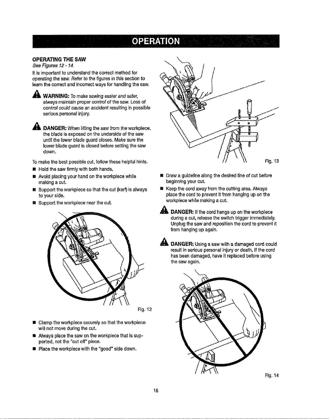
OPERATING THE SAW
See Figures 12- 14,,
Itis importantto understandthecorrect method for
operatingthe sawnRefertothe f/gumsinthis section to
learnthecorrect and incorrectwaysfor handlingthesaw,
,_ WARNING: Tomakesawingeasierandsafer,
alwaysmaintain propercontrolof thesaw°Lossof
controlcoutd causeanaccident resultingin possible
serious personalln]uryo
_1_ DANGER: When lifting the saw from the work'piece,
the blade is exposed on the underside of the saw
until the lower blade guard closes° Make sure the
lower blade guard is closed before setting the saw
down.
Tomake thebest possiblecut, follow thesehelpfulhints.
m Holdthe saw firmlywith bothhands.
m Avoid placingyour handon theworkptece while
making a cut.
Im Supporttheworkpiece sothat thecut (kerr)is always
to your side,
[] Supporttheworkpiecenearthe cut.
I Drawa guidelinealongthe desiredline of cut before
beginningyour cut.
[] Keepthecord awayfrom the cutting area.Always
placethecord to preventit from hangingup on the
workpiecewhilemaking a cut.
_ DANGER_If the cordhangs up on theworkplece
duringa cut, releasethe switch trigger immediately.
Unplugthe saw andrepositionthe cordto preventit
from hangingup again.
_, DANGER_ Using asaw with a damaged cord could
result in serious personal injury or death. If the cord
has been damaged, have It replaced before using
the saw again.
Fig. 12
= Clamp theworkpiecesecurelyso that theworkpiece
wiltnot moveduring thecut.
t Always placethe sawon theworkplece that issup-
ported, notthe "cut off"piece,
III Race theworkpiecewith the "good" sidedown.
16
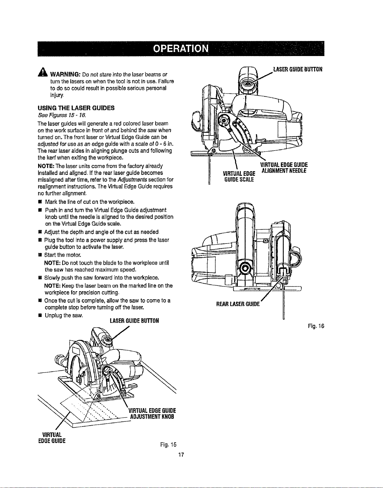
,_ WARNING: Donot stare into thetaserbeamsor
turnthe lasersonwhenthetool isnot in use,Failure
to do so couldresult inpossibleserious personal
tnjur/_
USING THE LASER GUIDES
See Figures 15- 16.
The laser guides will generate a red colored laser beam
on the work surface in front of and behind the saw when
turned on, The front laser or Virtual Edge Guide can be
ad}usted for use as an edge guide w_h a scale of 0 - 6 ino
The rear laser afdes in aligning plunge cuts and following
the kerf when exitingthe workpiece.
NOTE: The laser units come from the factory atready
installed and aUgned, If the rear laser guide becomes
misaligned after time, refer to the Adjustments section for
realignment instructions_The Virtual Edge Guide requires
no further alignment,
m Mark the line of cut on the workpiece.
= Push in and turn the Virtual Edge Guide adjustment
knob until the needle is aligned to the desired position
on the Virtual Edge Guide sca_e,
la Adjust the depth and angle of the cut as needed
m Plug the tool into a power supply and press the laser
gutde button to activate the _aser,
m Start the motor.
NOTE; Do not touch the blade to the workplece until
the saw has reached maximum speed,
[] Slowly push the saw forward into the workpiece.
NOTE: Keep the laser beam on the marked line on the
workpiece for precision cutting,
= Once the cut is complete, allow the saw to come to a
complete stop before turning off the taser.
= Unplug the saw,
LASERGUIDEBUTTON
REARLASERGUIDE
LASERGUIDEDUTTDN
VIRTUALEDGEGUIDE
ALIGNMENTNEEDLE
Fig, 16
"',, VIRTUALEDGEGUIDE
ADJUSTMENTKNOB
VIRTUAL
EDGEGUIDE
Fig, 15
17
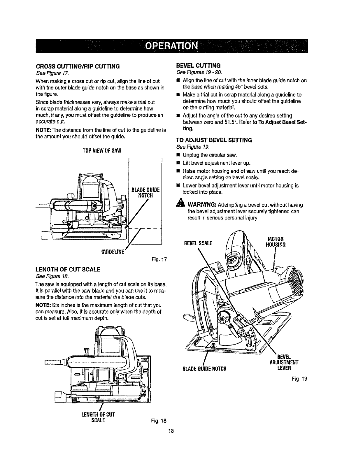
CROSS CUI-I'ING/RIP CUTTING
See Figure17",
Whenmakinga crosscutorrip cut,alignthe lineof cut
withthe outerblade guide notch on the baseasshown in
the figure.
Sinceblade thicknessesvary,alwaysmakea tdalcut
in scrapmateriaJalonga guidelineto determinehow
much,if any,you mustoffset the guidelineto producean
accuratecut.
NOTE:Thedistance fromtheline of cutto theguidelineis
the amountyou should offsetthe guide.
TOPVIEWOFSAW
BLADEGUIDE
NOTCH
GUIDEUNE"
LENGTH OF CUT SCALE
See Figure18o
Thesaw isequipped with a lengthofcutscale onitsbase,
It Isparallelwith the sawblade and youcan useit to mea-
surethedistance into thematerialtheblade cuts.
NOTE:Sixinchesisthe maximumlengthof cut that you
canmeasure.Also, it [saccurateonlywhenthe depth of
cut isset at fullmaximum depth.
BEVEL CUTTING
See Figures 19- 2&
! Alignthe lineof cut with theinnerbladeguide notch on
the basewhenmaking 45"bevelcuts.
R Make atrial cut Inscrap materialalonga gutdellneto
determinehow much youshould offsettheguideline
on the cutting materia!.
= Adjust the angleofthe cut to anydeelredsetting
between zeroand 5!.5 _.Referto ToAdjustBevelSet-
ring.
TO ADJUST BEVEL SETTING
SeeFigure f9
[] Unplugthe circularsaw.
m Lift beveladjusb'nentleverup.
[] Raisemotor housingend of saw untilyou reachde-
s_redan£tieset_in_{Inbevelscale,
I Lowerbeveladjustment teveruntilmotor housingis
locked Into pface.
,_ WARNING: Attempting a bevelcut without having
the bevel adjustmentleversecurelytightened can
result inserious personalinjury.
/
LENGTHOFCUT
SCALE
BLADEGUIDENOTCH
Fig. 18
Fig. 19
18

MAKING A BEVEL CUT
See Figure20
" HoTdthesawfirmlywithbothhandsas shown,
i Restthefront edgeofthebaseontheworkpieceo
i Startthesaw and letthe bladereachfullspeed°
m Guidethe saw intotheworkpieceandmake thecut,
[] Releasetheswitch triggerand allowthe bladeto come
to a completestop,
[] Lift the sawfrom theworkpiece,
Fig, 20
POSITIVE 0° BEVEL STOP
See Rgum21o
,_lk WARN|NG: Failuretounplug thetool couldresult in
accidentalstarting causingseriouspersonalinjury.
The saw has a positive 0° bevel stop that has been factory
adjusted to assure 0° angle of the saw blade when making
90° cuts.
CHECKING POSITIVE 0° BEVEL STOP
[] Unplugthecircularsawr
= Placethe sawin anupsidedownposition on a work-
bench,
[] Checkthesquarenessofthesawbladetothe baseof
thesaw usinga carpenter'ssquare.
ADJUSTING POSITIVE 0° BEVEL STOP
[] Unplugthe circularsaw.
[] Lift beve_adjustment_everup,
[] Turnsetscrewwith hexkey and adjust baseuntil it is
squarew_ththe sawb}ade.
[] Lowerbeveladjustmentleveruntilmotorhousingis
lockedinto place.
_ WARNING: Attemptinga bevelcutwithouthaving
thebeveladjustmentleversecurelytightenedcan
resultinseriouspersonalinjury°
CARPENTEIt'S
SETSCREW
Fig.21
19
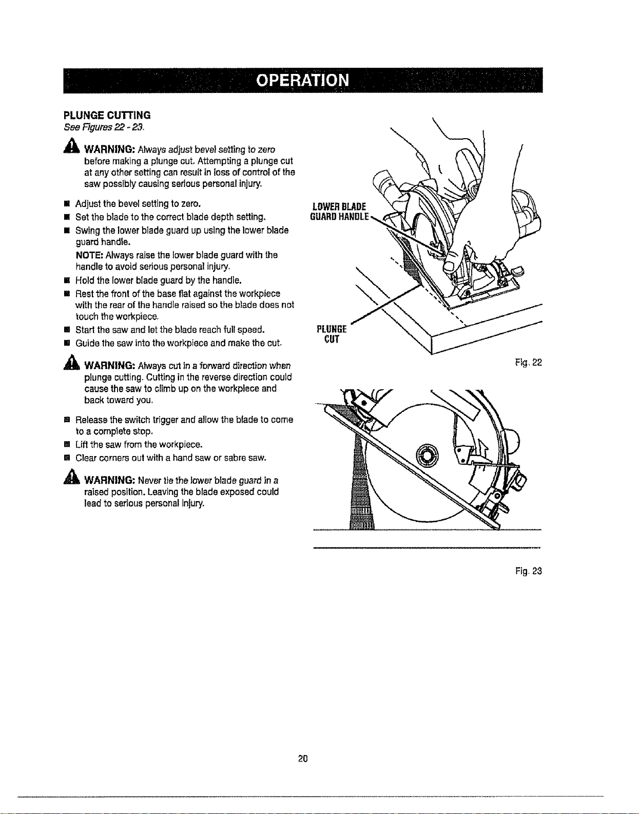
PLUNGE cUTrlNG
See Rgums 22.23.
_L WARN|NG: Ahvaysadjust bevelse_ng tozero
beforemakinga plungecut.Attempting a plunge cut
at anyother settingcan resuffinioss of control of the
saw possiblycausingseriouspersonalinjury,
m Adjust the bevelsettingtozero,
m Setthe blade to the correctblade depth setting°
E Swingthe lowerblade guard up usingthe lowerblade
guardhandle.
NOTE;Alwaysraisethelowerblade guard withthe
handleto avoidseriouspersona]injury.
= Hold the lowerblade guardby the handle.
E Restthe front ofthe baseflat againsttheworkpiece
with therear of thehandle raisedsothe bladedoes not
touchtheworkpiece.
m Start the sawand letthe bladereachfut[speed.
m Guide thesaw into theworkp}eceand makethe cut_
,_IIL WARNING: Ahvayscutinaforward dire_ionwhen
pfungecutting.Cutting inthe reversedirectioncould
causethesawto climb up onthe workpleceand
back toward you.
[] Release the switch trigger and allow the blade to come
to a complete stop.
[] Lift the saw from the workpiece.
[] Clear corners out with a hand saw or sabre saw.
_ll= WARN|NG: Nevertiethe lowerblade guard ina
raisedposition, Leavingthe blade exposedcould
lead to seriouspersonalInjury,
LOWERBLADE
GUARD
PLUNGE
CUT
Fig, 22
Fig 23
2O
A WARNING: Before performing any adjustment,
remove blade from saw. Failure to do so could result
in possible serious personal injury,
A WARNING: DONOT point the laserat yourself
orothers,ClassIlialaserswillbum the retinasand
couldcause sedousinjuryto the eyes.
A CAUTION: Use of controls or adjustments or
performance other than those specified herein may
result in hazardous radiation exposure,
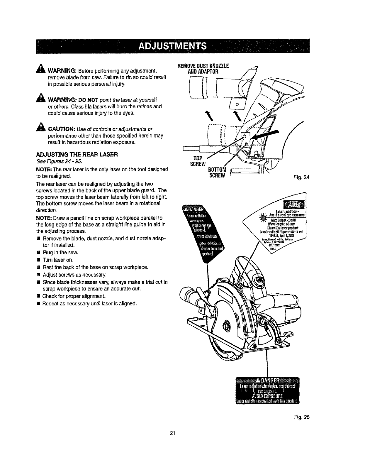
ADJUS'NNG THE REAR LASER
See Figures 24 - 25.
NOTE: The rear laser isthe only laser on the tool designed
to be realigned.
The rear laser can be realigned by adjusting the two
screws located in the back of the upper blade guard. The
top screw moves the laser beam laterallyfrom left to right.
The bottom screw moves the laser beam in a rotational
direction°
NOTE: Draw a pencil line on scrap workpiece parallel to
the long edge of the base as a stralght line guide to atd in
the adjusting process,
[] Remove the blade, dust nozzle, and dust nozzle adap-
tor if installed.
I Plug in the saw.
[] Turn laser on.
[] Rest the back of the base on scrap workpiece.
[] Adjust screws as necessary.
I Stnce blade thicknesses vary, always make a trial cut In
scrap workplace to ensure an accurate cut,
[] Check for proper alignment.
[] Repeat as necessary until laser is aligned.
REMOVEDUSTKNOZZLE
\ \iS/N .
t I
lopi
Fig. 25
21
_)' WARNING: When servicing, use one,' }dentica}
Craftsman replacement parts. Use of any other parts
may create a hazard or cause product damage.
A
WARNING: Alwayswearsafety gogglesor safety
glasseswith side shieldsdudng powertool operation
or whenblowing duel If operationis dusty,alsowear
a dust mask.
GENERAL MAINTENANCE
Avoiduslngsolventswhet]cleaningplast)cparts.Most
plastics aresusceptible to damagefrom varioustypesof
commercia}solventsand may be damagedby theiruse.
Usecleanclothsto removedirt, dust, o11,grease,etc.
_ll, WARNING: Do not atany timeletbrakefluids,
gasoline,petroleum-basedproducts,penetrating
oils,etc., comeincontact withplasticparts°
Chemicalscandamage,weakenor destroyplastic
which may resultInseriouspersonalinjury.
Electric toots used on tibergtass material, wallboard,
spacPJ{ng compounds, or plaster are subject to
accelerated wear and possible premature failure because
the fiberglass chips and gdnd[ngs are highly abrasive to
bearings, brushes, oommutators, etc..Consequent_, we
do not recommended us)rig this too}for extended work on
these types of materials. However, ff you do work with any
of these materials, it is extremely important to clean the
tool using compressed air.
LUBRICATION
A)]of thebearingsin thistoo_arelub_cated witha
sufficientamount of highgrade Jubricantfor the life of
theunitundernormal operatingconditions.Therefore,no
further lubricationisrequired.
Onlythepadsshown on the parts list are_ntendedto
be repairedor rep}acedby thecustomer.AItother parts
should be replacedat a SearsServiceCenter.
22
o
i=
Z
<_
n-
(J
\
m r_
_ m
_ w
E,=._
uJ
O
Z
23

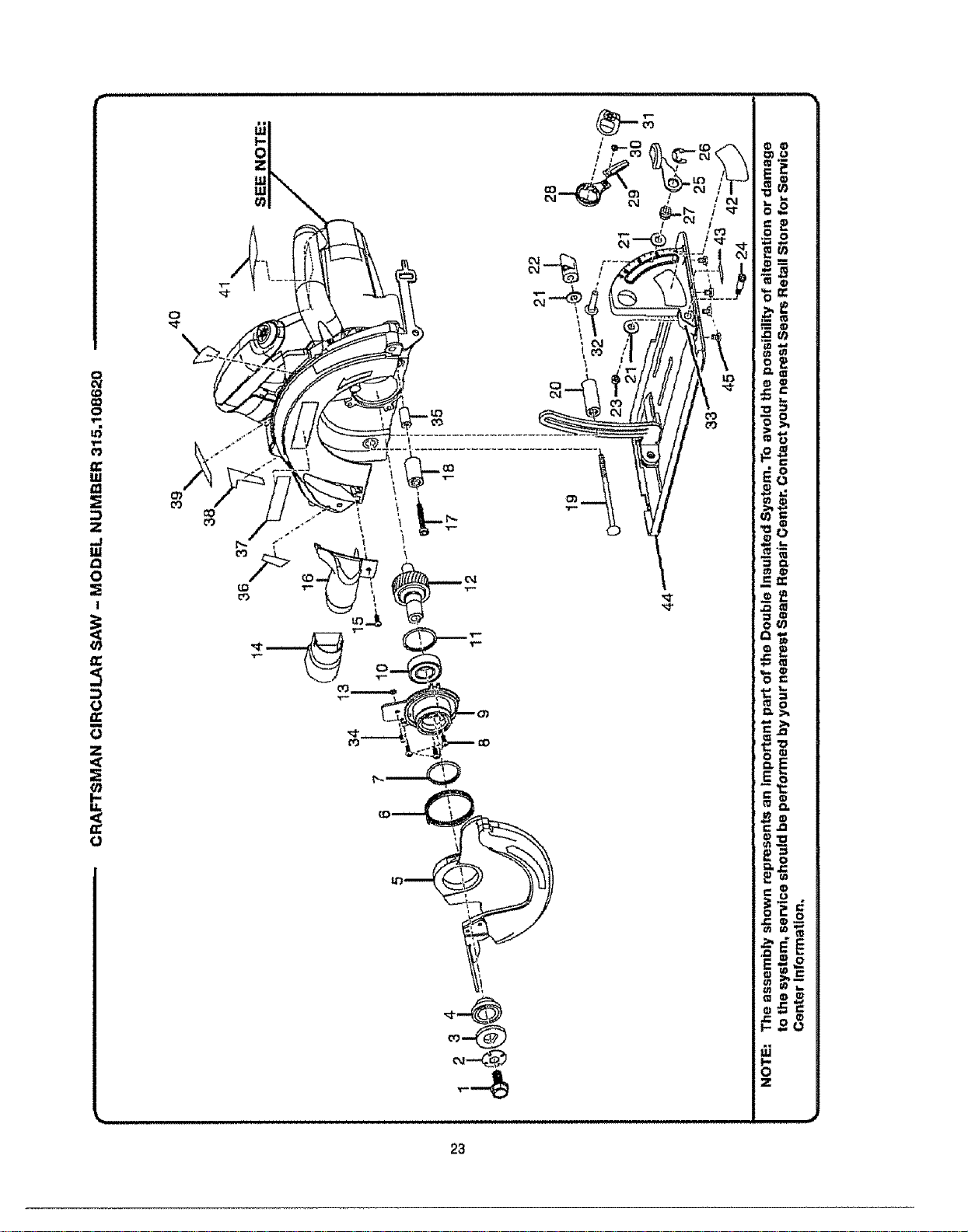
CRAFTSMAN CIRCULAR SAW - MODEL NUMBER 315.108620
,,,,,,,,,,,,,,,,,,, ,,,,,,,,,,,,,,,,,,,
The model number will be found on a plate attached to the motor housing. Always mention the model !
number in all correspondence regarding your CIRCULAR SAW or when ordedng repair parts. J
SEE BACK PAGE FOR PARTS ORDERING INSTRUCTIONS
Key
O.
1
2
3
4
5
6
7
8
g
10
1t
12
13
14
15
16
17
18
19
2O
21
22
23
24
25
26
27
28
29
3O
3t
32
33
34
35
36
37
38
39
40
41
42
43
44
45
Part
Number
660124001
680776001
680775001
680774001
300516027
671985001
680778001
660312001
641111001
680769001
680767001
300003018
680022001
550631002
660198001
551008001
660180003
560844001
660822001
550423004
680771001
550266003
67O974OO1
66O824OO1
301271001
671704001
671705001
513109001
341110001
660113008
513108001
660426001
640940001
660212005
690500001
941011002
940005054
940266003
940267003
940006110
940057057
941012001
941011001
300053016
660434003
983000817
=
, ,,,,, ,,,,,,,,,,,,,,,,,,,,,,,,,,,,,,,,,,,,,,,,,,,,,,,,,,,,,, ,,,,,
PARTS LIST
i
Description Qty.
Blade Screw ..................................................................................................... 1
Spring Washer ................................................................................................. 1
Outer Blade Washer ("D" Washer) ....................................................................................................1
Inner Flange Bushing ....................................................................................... 1
Lower Blade Guard Assembly ......................................................................... 1
Torsion Spring ..............................................................................................................................................1
Retaining Ring ................................................................................................. 1
* Screw (8-32 x 3/8 in,) *'STD510803 ................................................................ 3
Lower Guard Support ...................................................................................... 1
Ball Bearing (6003LLB) ..................................................................................... 1
Retaining Ring ................................................................................................. 1
Gear Assembly ................................................................................................ 1
° Hex Nut (M4 x 3,2) ........................................................................................... 1
Vacuum Adapter Nozzle ....................................................................................................1
* Screw (6-32 x 3/8 in. Pan Hd.) "=STD600603 .................................................. 1
Vacuum Adapter ............................................................................................... 1
* Screw (M5 x 32 mm) ............................................................................................. 1
Rubber Bumper ............................................................................................... 1
° Carriage Bolt (1/4-20 x 98 ram) ....................................................................... 1
Spacer ................................................................................................................. 1
Washer ............................................................................................................ 3
Knob ................................................................................................................ 1
Lock Nut (M5) ............................................................................................................ 1
Pivot Bolt (M5 x 25 ram) .................................................................................. 1
Lever Assembly ........................................................................................................................................1
E-Ring ....................................................................................................................... I
* Hex Nut (t/4-20) .............................................................................................. 1
Pointer Bracket ................................................................................................ 1
Pointer ...........................................................................................................................1
* Screw (M2.6 x 4 ram) ...................................................................................... 1
Knob ................................................................................................................. 1
* Carraige Bolt (1/4-20 x 28 mm) ............................................................................ 1
Bevel Bracket .................................................................................................. 1
* Screw (M4 x 8 ram) ......................................................................................... 1
Bumper Support.................................................................................................. 1
Rear Aperture Label ............................................................................................... 1
Logo Plate ........................................................................................................ 1
Scale Label (Depth of Cut) .............................................................................. 1
Spindle Lock Label.......................................................................................... 1
Laser Warning Label ....................................................................................... !
Data Label ........................................................................................................ 1
Pointer Scale Label ......................................................................................... 1
Front Aperture Label ....................................................................................... I
Base Assembly ................................................................................................. 1
* Screw (M5 x 8 mm Hex Flat Head) ................................................................. 4
Operator's Manual
* Standard Hardware Item - May Be Purchased Locally
** Available From Div, 98- Source 980.0
*** Complete assortment available at your Nearest Sears Retail Store
24

