Loading ...
Loading ...
Loading ...
DIGITAL CONTROL USER INPUT CONFIGURATION
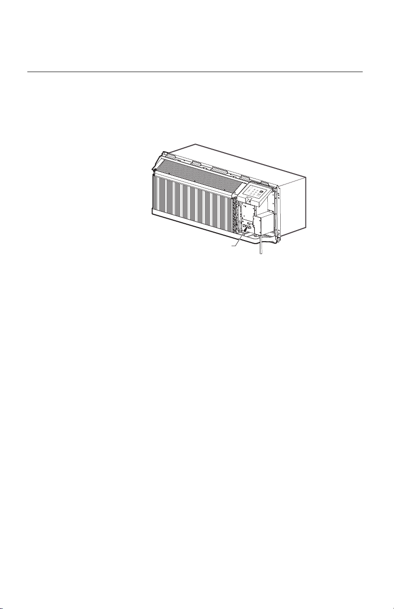
The adjustable control dip switches are located at the lower portion of the control box.
The inputs are only visible and accessible with the front cover removed from the PTAC.
DIP SWITCH SETTING
• Emergency Heat Override – Switch 1
In the unlikely event of a compressor failure a heat pump unit maybe switched to operate in
only the electric heat mode until repairs can be made. Move Dip Switch 1 up to ‘ON’.
• Wall Thermostat – Switch
2
To enable wall thermostat control and disable the keypad, move Dip Switch 2 up to 'ON’.
• Heating Fan Control – Switch 3
Set indoor fan to continuous mode with Dip Switch 3 up or cycle mode with Dip Switch 3
down (factory default).
• Cooling Fan Control – Switch 4
Set indoor fan to cycle mode with Dip Switch 4 up or continuous mode with Dip Switch 4
down (factory default).
• Electronic Temperature Limiting – Switches 5-6
The factory default temperature range is 65°F to 78°F. Three other temperature ranges may
be selected with the Dip Switches. See Table 4 for available ranges.
• Room Freeze Protection – Switch 7
Room Freeze Protection can be switched off at the owner’s preference by moving Dip Switch 7 up
to ‘OFF’. This feature will monitor the indoor room conditions and in the event that the room
falls below 40°F the unit will cycle on high fan with the electric heater. This occurs regardless
of mode. Units are shipped from the factory with the room freeze protection enabled.
SYSTEM CONFIGURATION
Fig. 17 – Dip Switch Location
1514
Location of
Dip Switches
on Unit
Loading ...
Loading ...
Loading ...