Loading ...
Mouli Engineering Inc. © 2014; U.S. Patent No. 8,716,889 Rev. 5 May 4, 2014
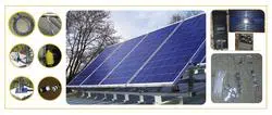
7. The A1 & A2 will then be attached to the B1 side of the bottom portion through the hinge nut.
Closeup of the hinge is given below. Tighten the hinge. (A1&A2 is the panel top half with coil of
wire)
8. The A3 & A4 will then be attached to the B2 side of the bottom portion through the hinge nut.
Attach the hinge as in (7) above.
9. Then the “A1 & A2” AND “A3 & A4” will be connected using the splice bar (flat 4 hole plate in the
box). There are two splice bars given in the box with hardware.
10. Two grade 8 “gold” bolts are used to fasten the telescopic legs to the appropriate tile angle. Now
the whole SolarPod
◌
TM
Standalone is all mechanically connected.
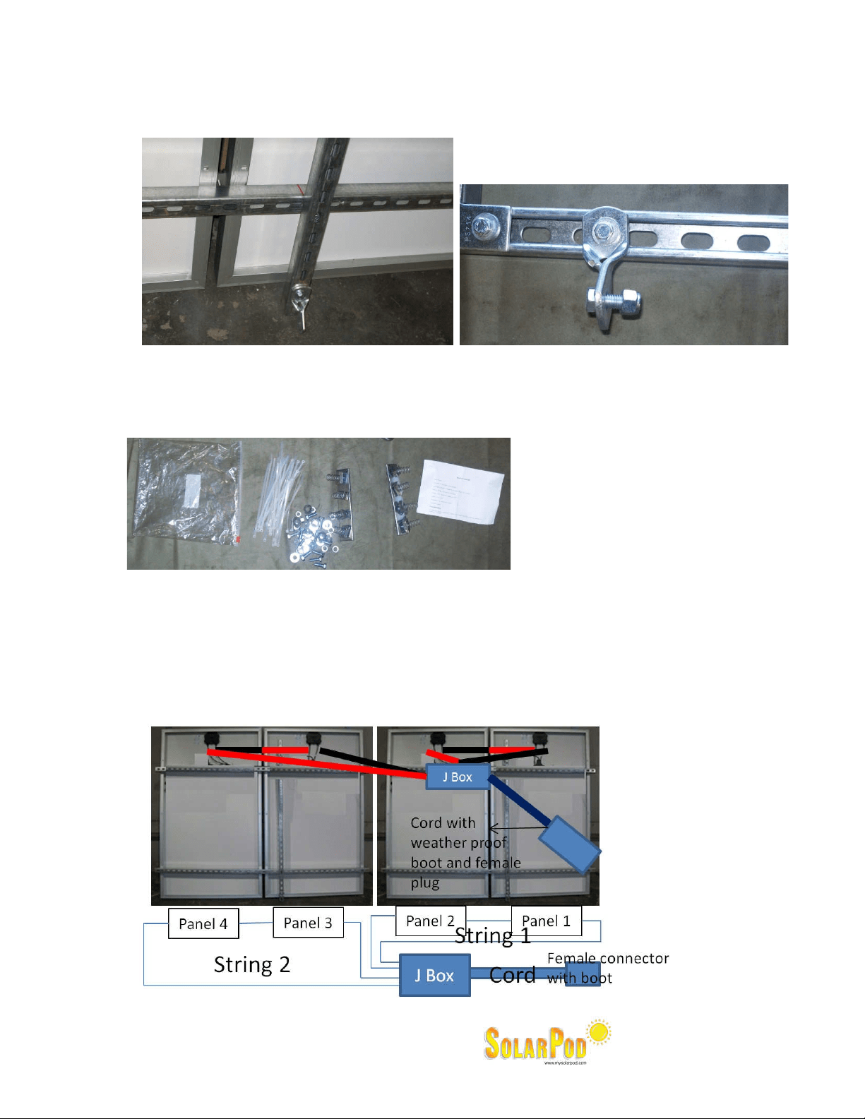
11. Now the electrical portion begins.
12. On the back of each panel, there will be a +ve and –ve wire. Connect the +ve of one to the –Ve
of the adjacent. The connections are shown pictorially in the figure below.
Four panel SolarPod
TM
for Model#1003, #1004 and #1005. String wiring per diagram below:
Loading ...
Loading ...
Loading ...