Loading ...
Loading ...
Loading ...
NOTE:Becarefulnottodamagethethreadsontheshaft,
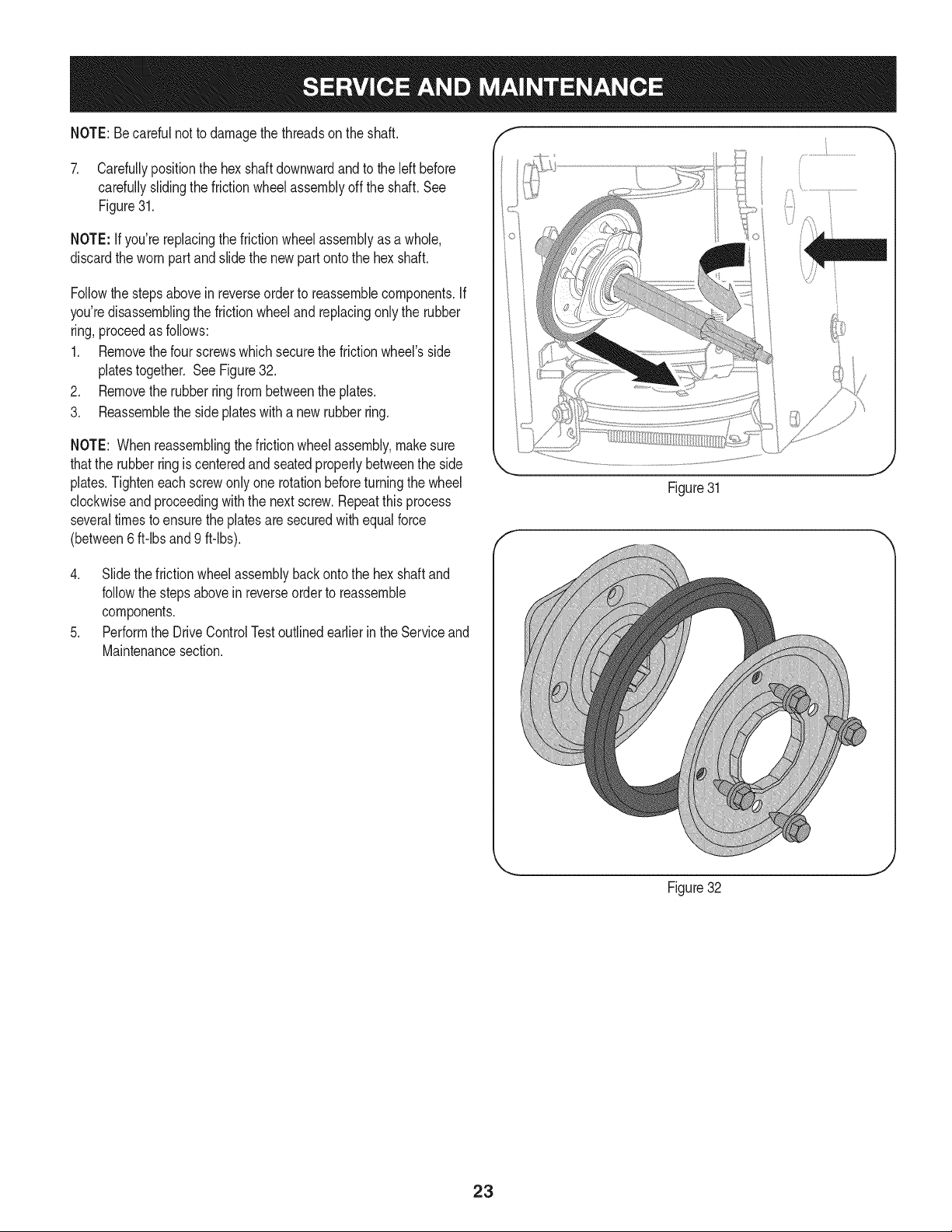
7. Carefullypositionthehexshaftdownwardandtotheleftbefore
carefullyslidingthefrictionwheelassemblyofftheshaft.See
Figure31.
NOTE:Ifyou'rereplacingthefrictionwheelassemblyasawhole,
discardthewornpartandslidethenewpartontothehexshaft.
Followthestepsaboveinreverseordertoreassemblecomponents.If
you'redisassemblingthefrictionwheelandreplacingonlytherubber
ring,proceedasfollows:
1. Removethefourscrewswhichsecurethefrictionwheel'sside
platestogether.SeeFigure32.
2. Removetherubberringfrombetweentheplates.
3. Reassemblethesideplateswithanewrubberring.
NOTE:Whenreassemblingthefrictionwheelassembly,makesure
thattherubberringiscenteredandseatedproperlybetweentheside
plates.Tighteneachscrewonlyonerotationbeforeturningthewheel
clockwiseandproceedingwiththenextscrew.Repeatthisprocess
severaltimestoensuretheplatesaresecuredwithequalforce
(between6ft-lbsand9ft-lbs).
4. Slidethefrictionwheelassemblybackontothehexshaftand
followthestepsaboveinreverseordertoreassemble
components.
5. PerformtheDriveControlTestoutlinedearlierintheServiceand
Maintenancesection.
Figure31
... j
Figure32
23
Loading ...
Loading ...
Loading ...