Loading ...
Loading ...
Loading ...
Page 9 1000002243 (Rev. H - 01/21)
EZSTLDWS*1G EZSTL8WS*1G, 2G, 3G LZSTLDWS*1G LZSTL8WS*1G, 2G, 3G
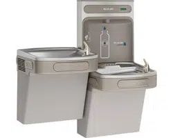
7/16” BOLT HOLES FOR
FASTENING UNIT TO WALL
UNIT CENTER LINE
TOP COVER
MOUNTING
SCREWS
Fig. 8 Fig. 9
31
Bottle Filler Installation Instructions
1) Remove two (2) mounting screws with 5/32” Allen wrench holding top cover to Bottle Filler (See Fig. 9). Remove top cover. Note do not discard mounting screws, they will be
needed to reinstall top cover.
2) Remove wall mounting plate from Bottle Filler. Place wall plate against wall on top of basin. Center the wall plate side to side with the basin. Mark the six (6) mounting holes
with a pencil (See Fig. 2, 3, 4 or 5).
3) Remove wall mounting plate from wall. NOTE: Mounting plate MUST be supported securely. Add xture support carrier if wall will not provide adequate support.
4) Install wall mounting plate to wall using six (6) 7/16” obround mounting holes (mounting bolts not included) (See Fig. 8). Use appropriate fasteners for your wall type.
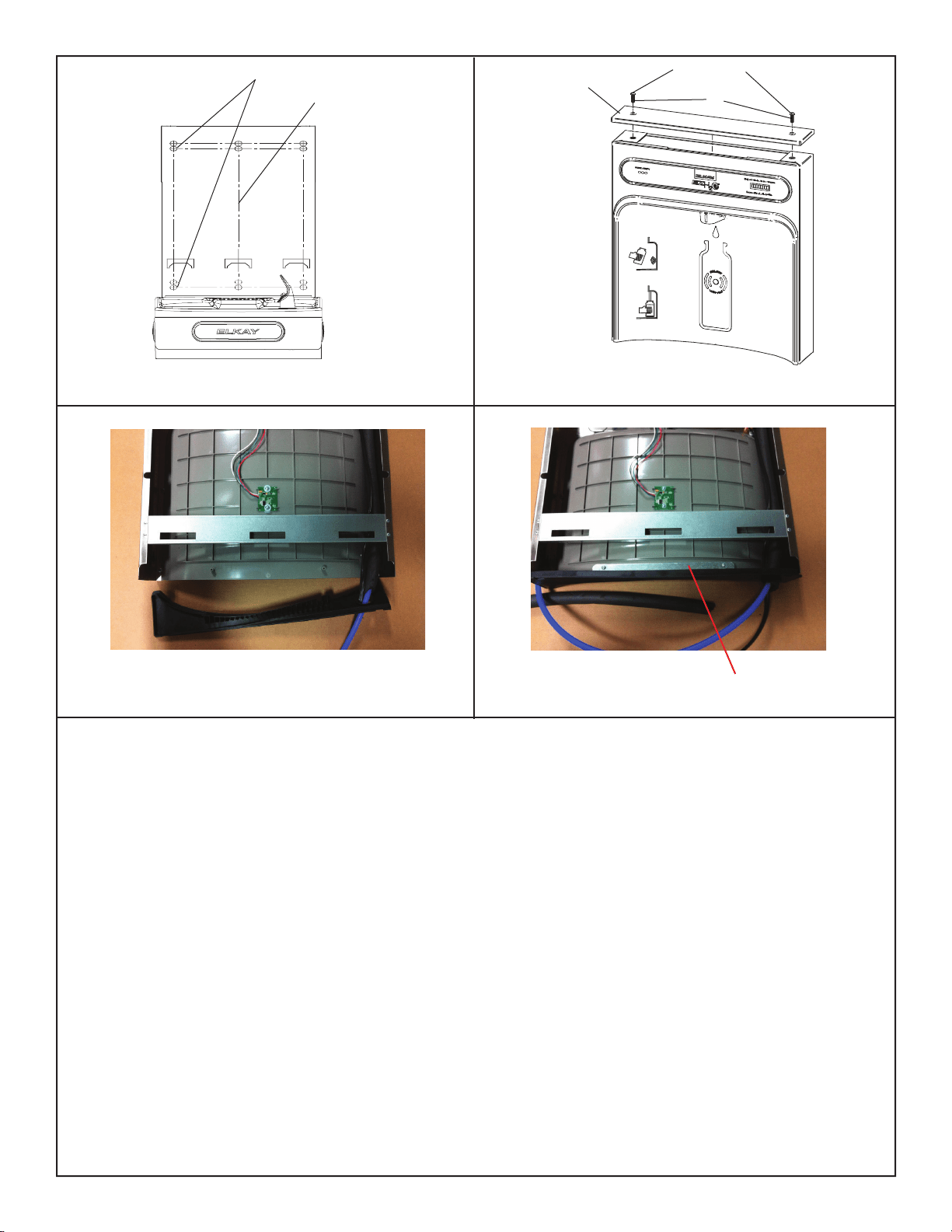
5) Lay Bottle Filler on water cooler basin and cut insulation from tube even with bottom of gasket, remove this insulation from the 3/8” tube, but do not discard.
Feed the power cord and waterline through the hole on top of water cooler. NOTE: To prevent scratching the basin place a towel or soft cloth over the entire basin when work-
ing above it.
6) Install gasket on bottom of bottle ller tower with gasket support bracket & (2) screws (See Fig. 11).
7) Feed power cord & 3/8” water line through hole in tower/basin gasket (See Fig. 10).
8) With the power cord, wire(s), and waterline through hole on top of water cooler place Bottle Filler on the three (3) angled tabs protruding from the wall mounting plate installed
on wall. Make sure round boss in gasket ts in hole of basin.
9) Once Bottle Filler is installed on wall plate tabs, water line, wire(s) and power cord are installed properly, push top of Bottle Filler toward wall and line up top cover two (2)
holes.
10) Reinstall Top Cover on Bottle Filler (See Fig. 9) with two mounting screws from step 1 above. Caution, do not over tighten screws.
11) Install remaining tube insulation to the water line from bottle ller, connect Bottle Filler waterline inside of the water cooler by connecting the 3/8” water line to the tee.
12) Install lter cartridge, remove lter from carton, remove protective cap, attach lter to lter head by rmly inserting into head and rotating lter clockwise.
13) Turn water supply on and inspect for leaks. Fix all leaks before continuing.
14) Once unit has been inspected for leaks and any leaks found corrected, plug Bottle Filler and unit into wall. Be sure to reinstall fuse to the circuit or
switch the circuit breaker back to the “ON” position.
15) Once power is applied to Bottle Filler, the GREEN LED light should illuminate showing good lter status along with the LCD Bottle Counter.
16) Verify proper dispensing by placing cup, hand, or any opaque object in front of sensor area and verify water dispenses. Note: the rst initial dispenses might have air in line
which may cause a sputter. This will be eliminated once all air is purged from the line.
17) Once unit tests out, install Lower Panel back on water cooler(s). Unit is now ready for use.
Fig. 11
Fig. 10
BRACKET & SCREWS
Loading ...
Loading ...
Loading ...