Loading ...
Loading ...
Loading ...
Simple INSTALLATION.
You can install your Zip HydroTap just about anywhere.
46
125
208 at rest
348
200 min.
A
Mains Cold water
isolation valve
240 - 230V, 50Hz
GPO
Pressure limiting
valve (supplied)
65 min.
382
SECTION A-A
4 min.
Buffer Pad
Air Space
15
35 Hole
HydroTap® Tap
Sink shown only
154
219
6
94
70
(
7 Hole)
314 at rest
92
C
L
Reach
232
DETAIL FONT
385
50 min.
50 min.
A
Clearance
Envelope
Clearance
Envelope
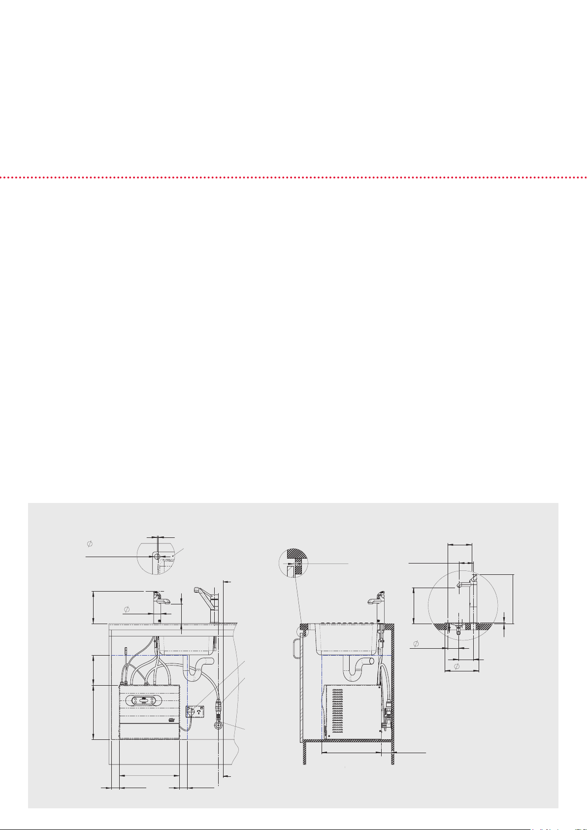
1. Zip HydroTap COMPACT 2
Location
The tap must be positioned so that it drains into a suitable
sink, or be installed on the optional "tap font kit". The tap
should be situated as closely as possible to directly above
the under-sink control cabinet. The maximum distance
from the base of the tap to the control cabinet is one
metre. The under-sink control cabinet must have top, side
and rear clearances as shown on the drawings.
Plumbing
Zip HydroTap must be installed in accordance with
AS/NZS 3500 plumbing regulations, and be connected to
a potable (drinkable) cold water supply. The Zip HydroTap
All-In-One and vented 4-In-One models require a water
supply which delivers at least two litres per minute at
a minimum dynamic pressure of 200 kPa. Other Zip
HydroTap models require 172 kPa minimum. A pressure
limiting valve (supplied) must be fitted at the time of
installation. An isolating valve (not supplied) must be fitted
between the control cabinet and the water supply. All
tubing connecting the tap to the cabinet must be taut for
proper drainage, and never coiled or looped.
Electrical
Models shown in this brochure should be connected to
a 10 amp GPO 220-240 volt AC power supply in accordance
with AS/NZS 3350 and 3000 wiring regulations.
Ventilation
For efficient operation, cupboards must be adequately
ventilated. Cupboard doors should be offset using 4 mm
buffers provided.
Carbon Dioxide
The CO2 gas cylinder supplied with "sparkling" models must be
secured in a suitable location using the strap provided. The gas
regulator supplied must be fitted. Each cylinder contains 1 Kg of
CO2 and should be installed in a well ventilated area or a room
of no less than 38 cubic metres. See website for gas cylinder
MSDS sheet for complete list of warnings.
Caution
In some hard water areas where mineral scale accumulation
can become a problem, consideration should be given to
the maintenance required. A suitable form of water treatment
may be necessary.
Loading ...
Loading ...
Loading ...