
Owner's Manual
ICHFTSMeN,I
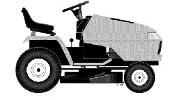
DEN TRACTOR
25.0 HP, 48" Mower
Electric Start
6 Speed Transaxle
Model No.
917.276011
This product has a low emission engine which operates
differently from previously built engines. Before you start the
engine, read and understand this Owner's Manual.
IMPORTANT:
Read and follow all Safety
Rules and Instructions before
operating this equipment.
For answers to your questions
about this product, Call:
1-800-659-5917
Sears Craftsman Help Line
5 am - 5 pm, Mon - Sat
SEARS, ROEBUCK AND CO., HOFFMAN ESTATES, IL 60179 U.S.A.
Visit our Craftsman website:www.sears.com/craftsman
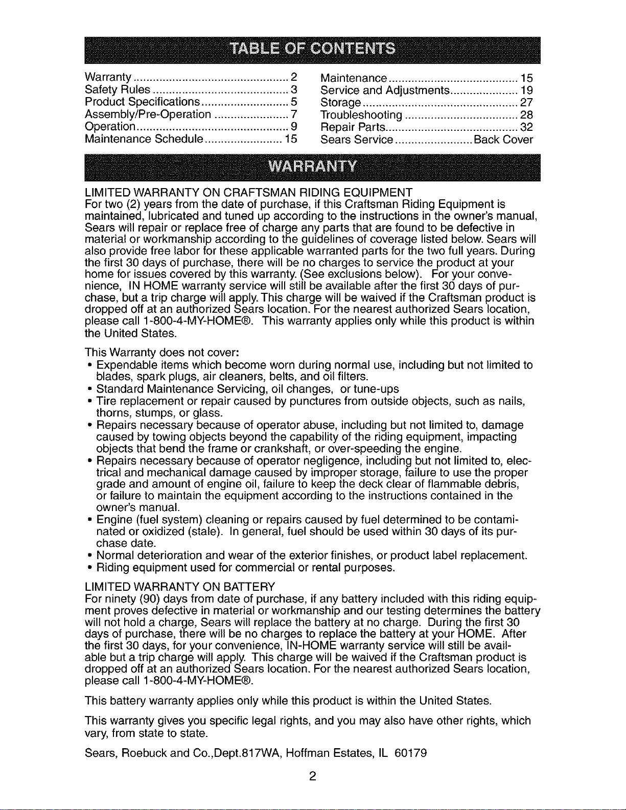
Warranty................................................2 Maintenance........................................15
SafetyRules..........................................3 ServiceandAdjustments.....................19
ProductSpecifications...........................5 Storage................................................27
Assembly/Pre-Operation.......................7 Troubleshooting...................................28
Operation...............................................9 RepairParts.........................................32
MaintenanceSchedule........................15 SearsService........................BackCover
LIMITEDWARRANTYONCRAFTSMANRIDINGEQUIPMENT
Fortwo(2)yearsfromthedateof purchase,if thisCraftsmanRidingEquipmentis
maintained,lubricatedandtuned upaccordingto the instructionsin theowner'smanual,
Searswill repairor replacefreeof chargeany partsthatare foundto be defectivein
materialor workmanshipaccordingto theguidelinesofcoveragelistedbelow.Searswill
alsoprovidefreelaborfortheseapplicablewarrantedparts forthe twofull years.During
thefirst 30 daysof purchase,there willbe nochargestoservicetheproductatyour
homefor issuescoveredbythiswarranty.(Seeexclusionsbelow). Foryourconve-
nience, INHOMEwarrantyservicewill still be availableafterthefirst 30 daysofpur-
chase,butatrip chargewillapply.This chargewill be waivediftheCraftsmanproductis
droppedoff at an authorizedSearslocation.ForthenearestauthorizedSearslocation,
pleasecall 1-800-4-MY-HOME®.This warrantyappliesonlywhilethis productis within
the UnitedStates.
ThisWarrantydoes notcover:
• Expendableitemswhichbecomewornduring normaluse, includingbutnotlimitedto
blades,spark plugs,air cleaners,belts,andoil filters.
• StandardMaintenanceServicing,oil changes, ortune-ups
• Tire replacementor repaircausedby puncturesfromoutsideobjects,suchas nails,
thorns,stumps,orglass.
• Repairsnecessarybecauseofoperatorabuse,includingbut notlimitedto,damage
causedbytowingobjectsbeyondthecapabilityofthe ridingequipment,impacting
objectsthatbendthe frameorcrankshaft,orover-speedingthe engine.
• Repairsnecessarybecauseofoperatornegligence,includingbutnotlimitedto, elec-
trical and mechanicaldamagecausedbyimproperstorage,failureto usetheproper
gradeandamountof engineoil, failureto keepthedeckclearofflammabledebris,
orfailureto maintaintheequipmentaccordingtothe instructionscontainedinthe
owner'smanual.
• Engine(fuelsystem)cleaningor repairscausedbyfuel determinedto becontami-
natedoroxidized(stale). Ingeneral,fuel shouldbe usedwithin30 daysof itspur-
chasedate.
• Normaldeteriorationand wearof theexteriorfinishes,orproductlabelreplacement.
• Ridingequipmentusedfor commercialor rentalpurposes.
LIMITEDWARRANTYON BATTERY
Forninety(90)daysfromdateof purchase,ifany batteryincludedwith thisridingequip-
mentprovesdefectivein materialorworkmanshipand ourtestingdeterminesthebattery
will notholda charge,Searswill replacethebatteryat no charge. Duringthefirst 30
daysof purchase,therewillbe no chargesto replacethebatteryat yourHOME. After
thefirst 30 days,for yourconvenience,IN-HOMEwarrantyservicewillstill be avail-
ablebutatripchargewill apply.This chargewill be waivediftheCraftsmanproductis
droppedoff at an authorizedSearslocation.ForthenearestauthorizedSearslocation,
pleasecall 1-800-4-MY-HOME®.
Thisbatterywarrantyappliesonlywhilethis productiswithinthe UnitedStates.
Thiswarrantygivesyouspecificlegalrights,andyou mayalsohaveother rights,which
vary,fromstateto state.
Sears,RoebuckandCo.,Dept.817WA,HoffmanEstates,IL 60179
2
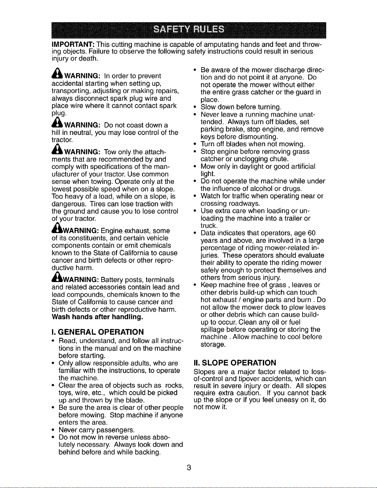
IMPORTANT: This cutting machine is capable of amputating hands and feet and throw-
ing objects. Failure to observe the following safety instructions could result in serious
injury or death.
_IWARNING: In order to prevent
accidental starting when setting up,
transporting, adjusting or making repairs,
always disconnect spark plug wire and
place wire where it cannot contact spark
plug.
,_WARNING: Do not coast down a
hill in neutral, you may lose control of the
tractor.
_WARNING: Tow only the attach-
ments that are recommended by and
comply with specifications of the man-
ufacturer of your tractor. Use common
sense when towing. Operate only at the
lowest possible speed when on a slope.
Too heavy of a load, while on a slope, is
dangerous. Tires can lose traction with
the ground and cause you to lose control
of your tractor.
_WARNING: Engine exhaust, some
of its constituents, and certain vehicle
components contain or emit chemicals
known to the State of California to cause
cancer and birth defects or other repro-
ductive harm.
_WARNING: Battery posts, terminals
and related accessories contain lead and
lead compounds, chemicals known to the
State of California to cause cancer and
birth defects or other reproductive harm.
Wash hands after handling.
I. GENERAL OPERATION
• Read, understand, and follow all instruc-
tions in the manual and on the machine
before starting.
• Only allow responsible adults, who are
familiar with the instructions, to operate
the machine.
• Clear the area of objects such as rocks,
toys, wire, etc., which could be picked
up and thrown by the blade.
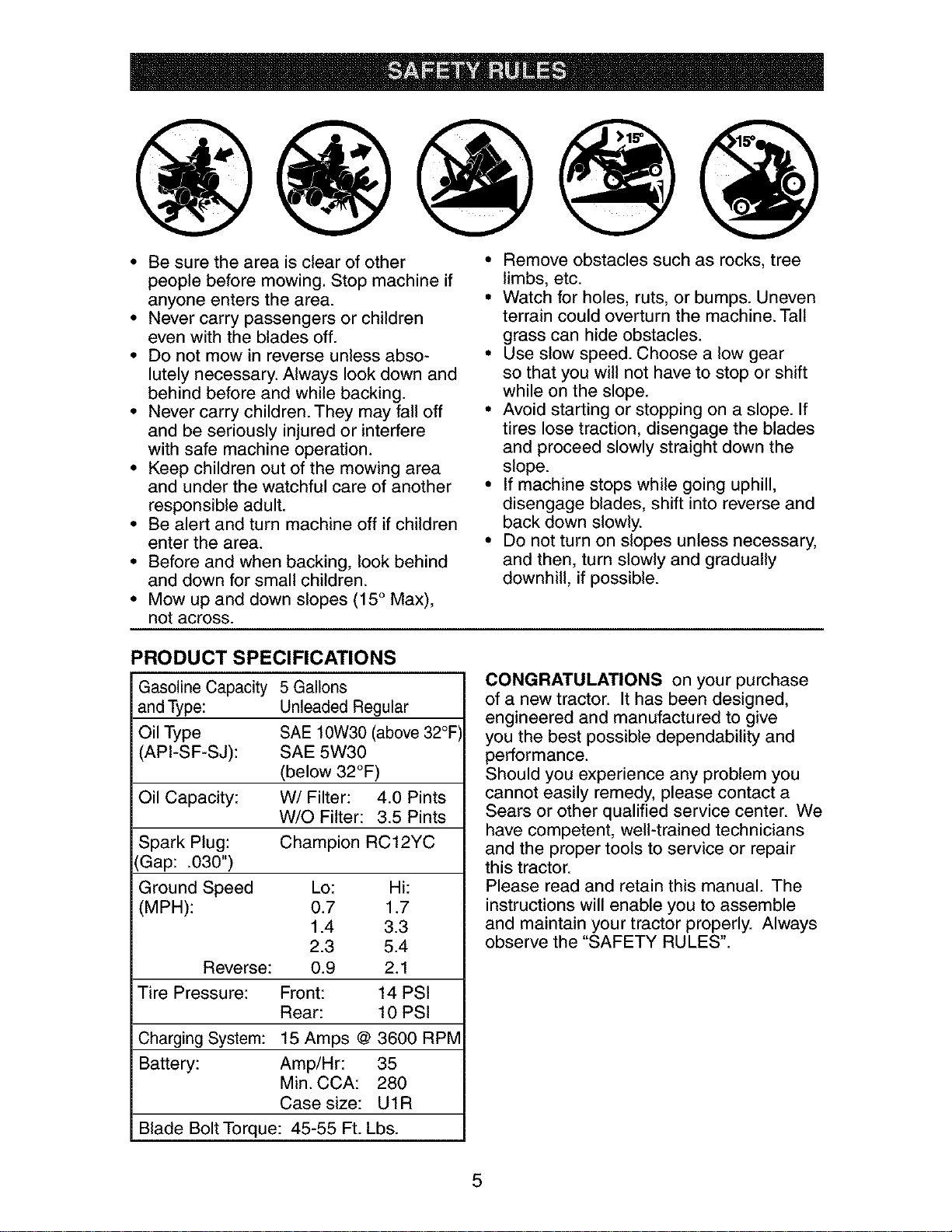
• Be sure the area is clear of other people
before mowing. Stop machine if anyone
enters the area.
• Never carry passengers.
• Do not mow in reverse unless abso-
lutely necessary. Always look down and
behind before and while backing.
• Be aware of the mower discharge direc-
tion and do not point it at anyone. Do
not operate the mower without either
the entire grass catcher or the guard in
place.
• Slow down before turning.
• Never leave a running machine unat-
tended. Always turn off blades, set
parking brake, stop engine, and remove
keys before dismounting.
• Turn off blades when not mowing.
• Stop engine before removing grass
catcher or unclogging chute.
• Mow only in daylight or good artificial
light.
• Do not operate the machine while under
the influence of alcohol or drugs.
• Watch for traffic when operating near or
crossing roadways.
• Use extra care when loading or un-
loading the machine into a trailer or
truck.
• Data indicates that operators, age 60
years and above, are involved in a large
percentage of riding mower-related in-
juries. These operators should evaluate
their ability to operate the riding mower
safely enough to protect themselves and
others from serious injury.
• Keep machine free of grass, leaves or
other debris build-up which can touch
hot exhaust / engine parts and burn. Do
not allow the mower deck to plow leaves
or other debris which can cause build-
up to occur. Clean any oil or fuel
spillage before operating or storing the
machine. Allow machine to cool before
storage.
II. SLOPE OPERATION
Slopes are a major factor related to loss-
of-control and tipover accidents, which can
result in severe injury or death. All slopes
require extra caution. If you cannot back
up the slope or if you feel uneasy on it, do
not mow it.
3

DO:
• Mow up and down slopes, not across.
• Remove obstacles such as rocks, tree
limbs, etc.
• Watch for holes, ruts, or bumps. Un-
even terrain could overturn the machine.
Tall grass can hide obstacles.
• Use slow speed. Choose a low gear
so that you will not have to stop or shift
while on the slope.
• Follow the manufacturer's recommend-
ations for wheel weights or counter-
weights to improve stability.
• Use extra care with grass catchers or
other attachments. These can change
the stability of the machine.
• Keep all movement on the slopes slow
and gradual Do not make sudden
changes in speed or direction.
• Avoid starting or stopping on a slope. If
tires lose traction, disengage the blades
and proceed slowly straight down the
slope.
DO NOT:
• Do not turn on slopes unless neces-
sary, and then, turn slowly and gradually
downhill, if possible.
• Do not mow near drop-offs, ditches,
or embankments. The mower could
suddenly turn over if a wheel is over
the edge of a cliff or ditch, or if an edge
caves in.
• Do not mow on wet grass. Reduced
traction could cause sliding.
• Do not try to stabilize the machine by
putting your foot on the ground.
• Do not use grass catcher on steep
slopes.
III. CHILDREN
Tragic accidents can occur if the operator
is not alert to the presence of children.
Children are often attracted to the ma-
chine and the mowing activity. Neveras-
sume that children will remain where you
last saw them.
• Keep children out of the mowing area
and under the watchful care of another
responsible adult.
• Be alert and turn machine off if children
enter the area.
• Before and when backing, look behind
and down for small children.
• Never carry children. They may fall off
and be seriously injured or interfere with
safe machine operation.
Never allow children to operate the
machine.
Use extra care when approaching blind
corners, shrubs, trees, or other objects
that may obscure vision.
IV. SERVICE
• Use extra care in handling gasoline and
other fuels. They are flammable and
vapors are explosive.
- Use only an approved container.
- Never remove gas cap or add fuel
with the engine running. Allow
engine to cool before refueling. Do
not smoke.
- Never refuel the machine indoors.
- Never store the machine or fuel
container inside where there is an
open flame, such as a water heater.
• Never run a machine inside a closed
area.
• Keep nuts and bolts, especially blade
attachment bolts, tight and keep equip-
ment in good condition.
• Never tamper with safety devices.
Check their proper operation regularly.
• Keep machine free of grass, leaves, or
other debris build-up. Clean oil or fuel
spillage. Allow machine to cool before
storing.
• Stop and inspect the equipment if you
strike an object. Repair, if necessary,
before restarting.
• Never make adjustments or repairs with
the engine running.
• Grass catcher components are subject
to wear, damage, and deterioration,
which could expose moving parts or
allow objects to be thrown. Frequently
check components and replace with
manufacturer's recommended parts,
when necessary.
• Mower blades are sharp and can cut.
Wrap the blade(s) or wear gloves, and
use extra caution when servicing them.
• Check brake operation frequently. Ad-
just and service as required.
4
• Be sure the area is clear of other
people before mowing. Stop machine if
anyone enters the area.
• Never carry passengers or children
even with the blades off.
• Do not mow in reverse unless abso-
lutely necessary. Always look down and
behind before and while backing.
• Never carry children. They may fall off
and be seriously injured or interfere
with safe machine operation.
• Keep children out of the mowing area
and under the watchful care of another
responsible adult.
• Be alert and turn machine off if children
enter the area.
• Before and when backing, look behind
and down for small children.
• Mow up and down slopes (15° Max),
not across.
• Remove obstacles such as rocks, tree
limbs, etc.
• Watch for holes, ruts, or bumps. Uneven
terrain could overturn the machine. Tall
grass can hide obstacles.
• Use slow speed. Choose a low gear
so that you will not have to stop or shift
while on the slope.
• Avoid starting or stopping on a slope. If
tires lose traction, disengage the blades
and proceed slowly straight down the
slope.
• If machine stops while going uphill,
disengage blades, shift into reverse and
back down slowly.
• Be not turn on slopes unless necessary,
and then, turn slowly and gradually
downhill, if possible.
PRODUCT SPECIFICATIONS
Gasoline Capacity 5 Gallons
and Type: Unleaded Regular
Oil Type SAE 10W30 (above 32°F
API-SF-SJ): SAE 5W30
(below 32°F)
Oil Capacity: W/Filter: 4.0 Pints
W/O Filter: 3.5 Pints
Spark Plug: Champion RC12YC
(Gap: .030")
Ground Speed Lo: Hi:
(MPH): 0.7 1.7
1.4 3.3
2.3 5.4
Reverse: 0.9 2.1
Tire Pressure: Front: 14 PSI
Rear: 10 PSI
Charging System: 15 Amps @ 3600 RPM
Battery: Amp/Hr: 35
Min. CCA: 280
Case size: UIR
Blade Bolt Torque: 45-55 Ft. Lbs.
CONGRATULATIONS on your purchase
of a new tractor. It has been designed,
engineered and manufactured to give
you the best possible dependability and
performance.
Should you experience any problem you
cannot easily remedy, please contact a
Sears or other qualified service center. We
have competent, well-trained technicians
and the proper tools to service or repair
this tractor.
Please read and retain this manual. The
instructions will enable you to assemble
and maintain your tractor properly. Always
observe the "SAFETY RULES".
5
CUSTOMER RESPONSIBILITIES
• Read and observe the safety rules.
• Follow a regular schedule in main-
taining, caring for and using your tractor.
• Follow the instructions under "Mainte-
nance" and "Storage" sections of this
owner's manual.
A(_WARNING: This tractor is equipped
with an internal combustion engine and
should not be used on or near any unim-
proved forest-covered, brush-covered or
grass-covered land unless the engine's
exhaust system is equipped with a spark
arrester meeting applicable local or state
laws (if any). If a spark arrester is used, it
should be maintained in effective working
order by the operator.
In the state of California the above is re-
quired by law (Section 4442 of the Califor-
nia Public Resources Code). Other states
may have similar laws. Federal laws apply
on federal lands. A spark arrester for the
muffler is available through your nearest
Sears service center (See REPAIR PARTS
section of this manual).
REPAIR PROTECTION
AGREEMENTS
Congratulations on making a smart pur-
chase. Your new Craftsman® product is
designed and manufactured for years of
dependable operation. But like all prod-
ucts, it may require repair from time to
time. That's when having a Repair Protec-
tion Agreement can save you money and
aggravation.
Purchase a Repair Protection Agreement
now and protect yourself from unexpected
hassle and expense.
Here's what's included in the Agreement:
• Expert service by our 12,000 profe-
sional repair specialists.
• Unlimited service and no charge for
parts and labor on all covered repairs.
• Product replacement ifyour covered
product can't be fixed.
• Discount of 10% from regular price of
service and service-related parts not
covered by the agreement; also, 10%
off regular price of preventive mainte-
nance check.
• Fast help by phone- phone support
from a Sears technician on products
requiring in-home repair, plus conve-
nient repair scheduling.
Once you purchase the Agreement, a
simple phone call is all that it takes for you
to schedule service. You can call anytime
day or night, or schedule a service ap-
pointment online.
Sears has over 12,000 professional repair
specialists, who have access to over 4.5
million quality parts and accessories.
That's the kind of professionalism you can
count on to help prolong the life of your
new purchase for years to come. Purchase
your Repair Protection Agreement today!
Some limitations and exclusions apply.
For prices and additional information
call 1-800-827-6655.
SEARS INSTALLATION SERVICE
For Sears professional installation of home
appliances, garage door openers, water
heaters, and other major home items, in
the U.S.A. call 1-800-4-MY-HOME®
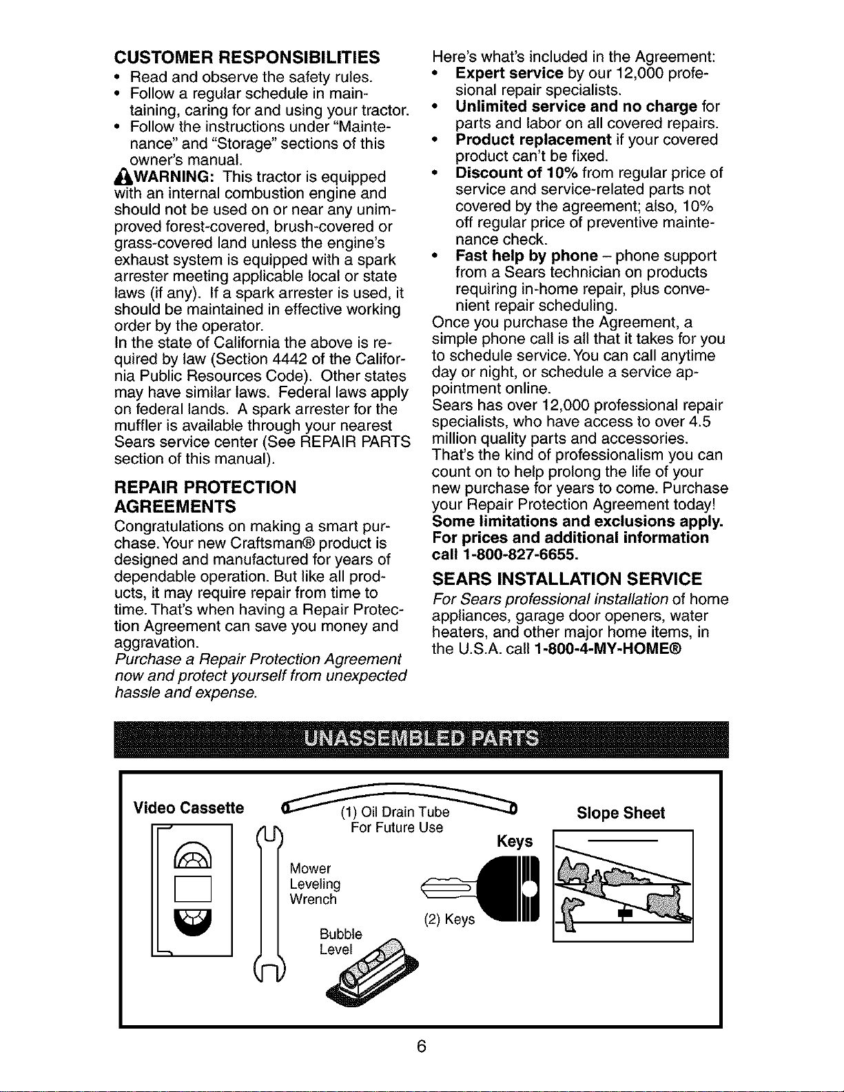
Video Cassette
"-'t
l
Mower
Leveling
Wrench
For Future Use
Keys
Bubble
Slope Sheet
6
Your new tractor has been assembled at the factory. Review the video cassette before
you begin.
When right or left hand is mentioned in
this manual, it means, from your point of
view, when you are in the operating posi-
tion (seated behind the steering wheel)•
TO REMOVE TRACTOR FROM
CARTON
UNPACK CARTON
1. Cut along dotted lines on all four pan-
els of carton• Remove end panels and
lay side panels flat.
2. Remove packing materials.
3. Remove protective materials from
tractor hood and grille•
IMPORTANT: Check for and remove any
staples in skid that may puncture tires
where tractor is to roll off skid.
HOW TO SET UP YOUR TRACTOR
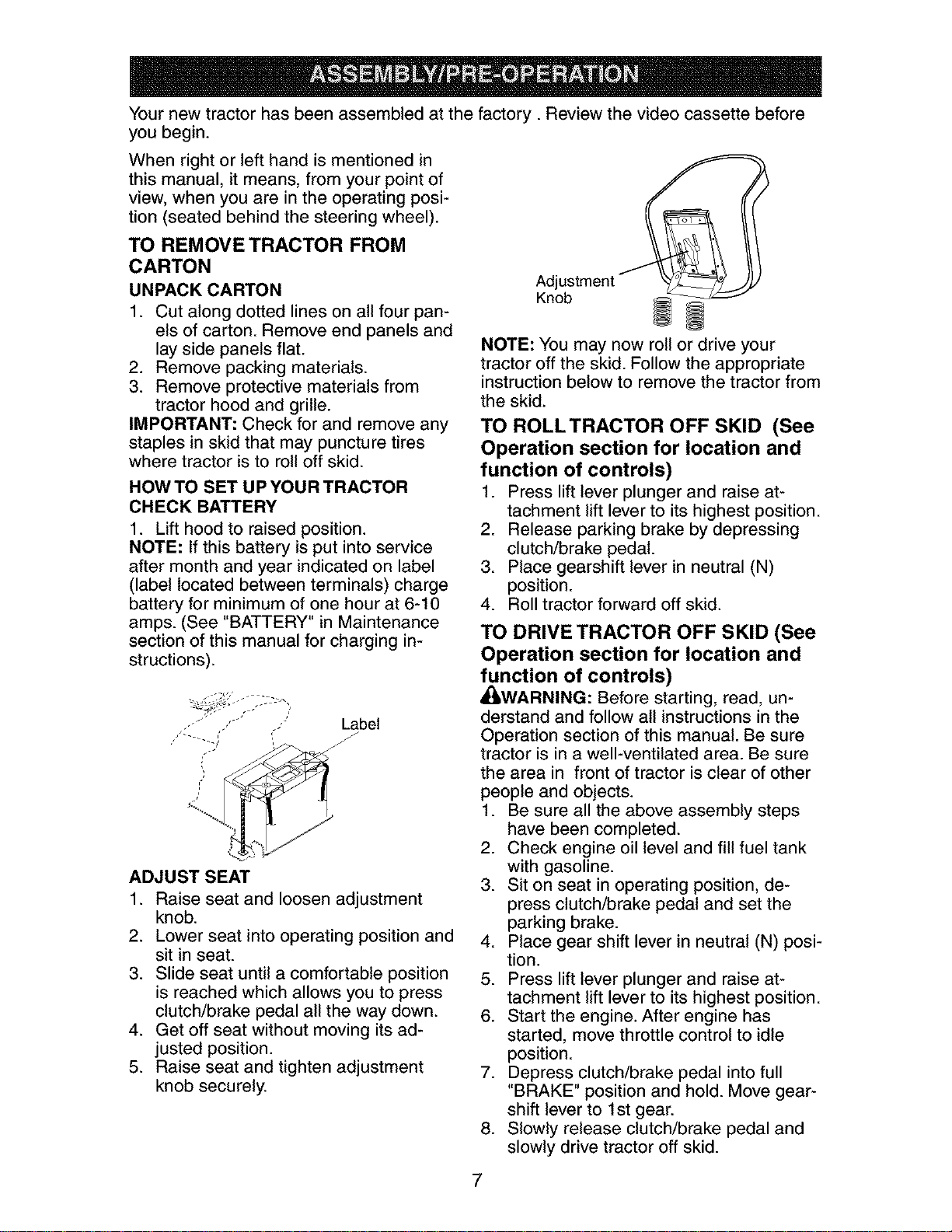
CHECK BATTERY
1. Lift hood to raised position.
NOTE: If this battery is put into service
after month and year indicated on label
(label located between terminals) charge
battery for minimum of one hour at 6-10
amps. (See "BATTERY" in Maintenance
section of this manual for charging in-
structions).
,..' .,'- Label
i-
ADJUST SEAT
1. Raise seat and loosen adjustment
knob.
2. Lower seat into operating position and
sit in seat.
3. Slide seat until a comfortable position
is reached which allows you to press
clutch/brake pedal all the way down.
4. Get off seat without moving its ad-
justed position.
5. Raise seat and tighten adjustment
knob securely.
Adjustment
nob
NOTE: You may now roll or drive your
tractor off the skid• Follow the appropriate
instruction below to remove the tractor from
the skid.
TO ROLLTRACTOR OFF SKID (See
Operation section for location and
function of controls)
1. Press lift lever plunger and raise at-
tachment lift lever to its highest position•
2. Release parking brake by depressing
clutch/brake pedal•
3. Place gearshift lever in neutral (N)
position•
4. Roll tractor forward off skid.
TO DRIVE TRACTOR OFF SKID (See
Operation section for location and
function of controls)
_WARNING: Before starting, read, un-
derstand and follow all instructions in the
Operation section of this manual• Be sure
tractor is in a well-ventilated area. Be sure
the area in front of tractor is clear of other
people and objects.
1. Be sure all the above assembly steps
have been completed.
2. Check engine oil level and fill fuel tank
with gasoline.
3. Sit on seat in operating position, de-
press clutch/brake pedal and set the
parking brake•
4. Place gear shift lever in neutral (N) posi-
tion.
5. Press lift lever plunger and raise at-
tachment lift lever to its highest position•
6. Start the engine. After engine has
started, move throttle control to idle
position•
7. Depress clutch/brake pedal into full
"BRAKE" position and hold. Move gear-
shift lever to 1st gear.
8. Slowly release clutch/brake pedal and
slowly drive tractor off skid.
7
9. Apply brake to stop tractor, set park-
ing brake and place gearshift lever in
neutral position.
10.Turn ignition key to "STOP" position.
Continue with the instructions that follow.
CHECKTIRE PRESSURE
The tires on your tractor were overinflated
at the factory for shipping purposes. Cor-
rect tire pressure is important for best
cutting performance.
• Reduce tire pressure to PSI shown in
"PRODUCT SPECIFICATIONS" section
of this manual.
CHECK DECK LEVELNESS
For best cutting results, mower hous-
ing should be properly leveled. See "TO
LEVEL MOWER HOUSING" in the Service
and Adjustments section of this manual.
CHECK FOR PROPER POSITION
OF ALL BELTS
See the figures that are shown for replac-
ing motion and mower blade drive belts
in the Service and Adjustments section
of this manual. Verify that the belts are
routed correctly.
CHECK BRAKE SYSTEM
After you learn how to operate your trac-
tor, check to see that the brake is properly
adjusted. See "TO ADJUST BRAKE" in
the Service and Adjustments section of
this manual.
J CHECKLIST
Before you operate your new tractor, we
wish to assure that you receive the best
performance and satisfaction from this
Quality Product.
Please review the following checklist:
,/All assembly instructions have been
completed.
,/No remaining loose parts in carton.
,/Battery is properly prepared and
charged. (Minimum 1 hour at 6 amps).
,/Seat is adjusted comfortably and tight-
ened securely.
,/All tires are properly inflated. (For ship-
ping purposes, the tires were overin-
flated at the factory).
,/Be sure mower deck is properly leveled
side-to-side/front-to-rear for best cutting
results. (Tires must be properly inflated
for leveling).
,/Check mower and drive belts. Be sure
they are routed properly around pulleys
and inside all belt keepers.
,/Check wiring. See that all connections
are still secure and wires are properly
clamped.
While learning how to use your tractor, pay
extra attention to the following important
items:
,/Engine oil is at proper level.
,/Fuel tank is filled with fresh, clean, regu-
lar unleaded gasoline.
,/Become familiar with all controls, their
location and function. Operate them
before you start the engine.
,/Be sure brake system is in safe operat-
ing condition.
8
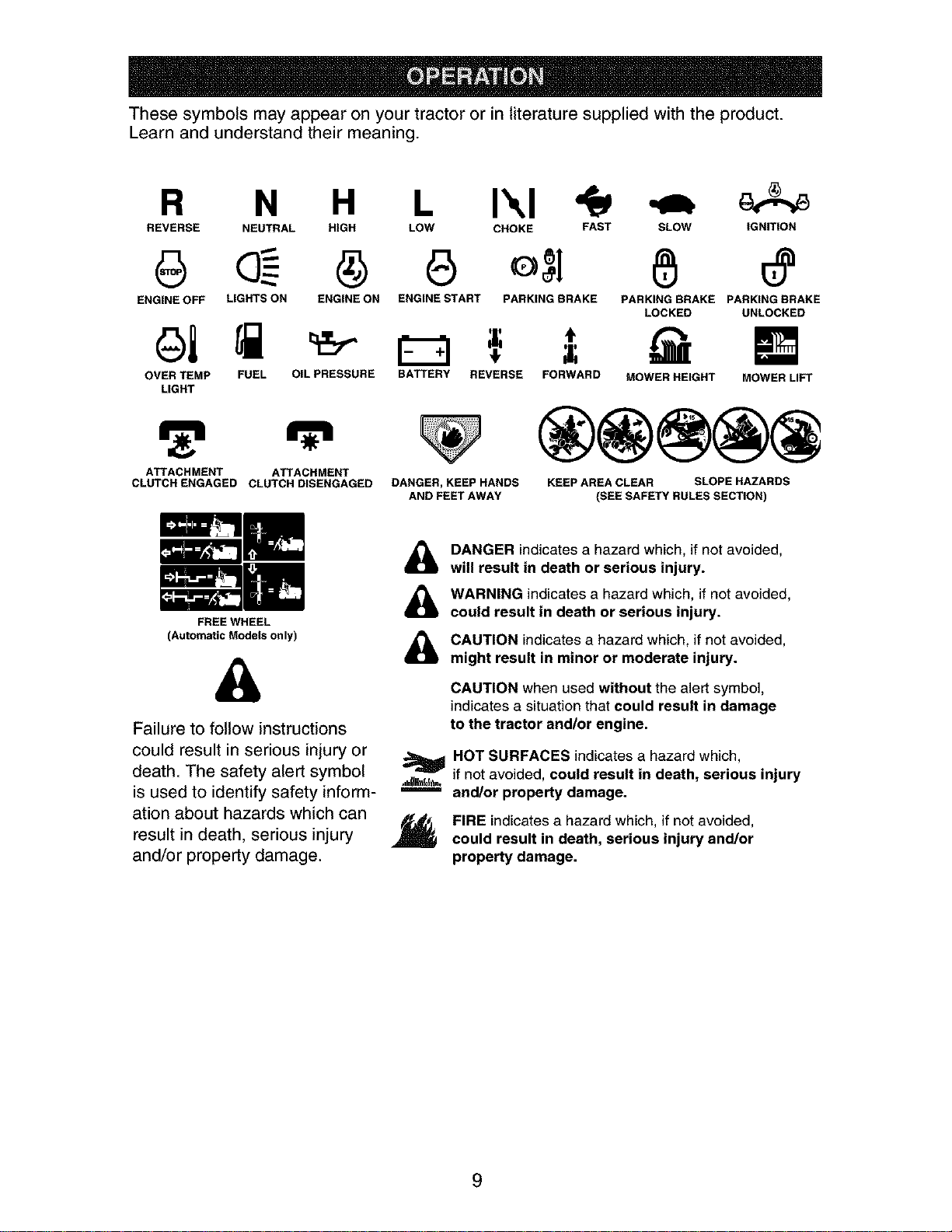
These symbols may appear on your tractor or in literature supplied with the product.
Learn and understand their meaning.
R N H L I'.,I
REVERSE NEUTRAL HIGH LOW CHOKE FAST SLOW IGNITION
ENGINE OFF LIGHTS ON ENGINE ON ENGINE START PARKING BRAKE PARKING BRAKE PARKING BRAKE
LOCKED UNLOCKED
OVER TEMP FUEL OIL PRESSURE BATTERY REVERSE FORWARD
LIGHT
ATTACHMENT ATTACHMENT
CLUTCH ENGAGED CLUTCH DISENGAGED
FREE WHEEL
(Automatic Models only)
&
Failure to follow instructions
could result in serious injury or
death. The safety alert symbol
is used to identify safety inform-
ation about hazards which can
result in death, serious injury
and/or property damage.
MOWER HEIGHT MOWER LIFT
DANGER, KEEP HANDS
AND FEET AWAY
KEEP AREA CLEAR SLOPE HAZARDS
(SEE SAFETY RULES SECTION)
&
&
&
m
DANGER indicates a hazard which, if not avoided,
will result in death or serious injury.
WARNING indicates a hazard which, if not avoided,
could result in death or serious injury.
CAUTION indicates a hazard which, if not avoided,
might result in minor or moderate injury.
CAUTION when used without the alert symbol,
indicates a situation that could result in damage
to the tractor and/or engine.
HOT SURFACES indicates a hazard which,
if not avoided, could result in death, serious injury
and/or property damage.
FIRE indicatesa hazard which, if not avoided,
could result in death, serious injury and/or
property damage.
9
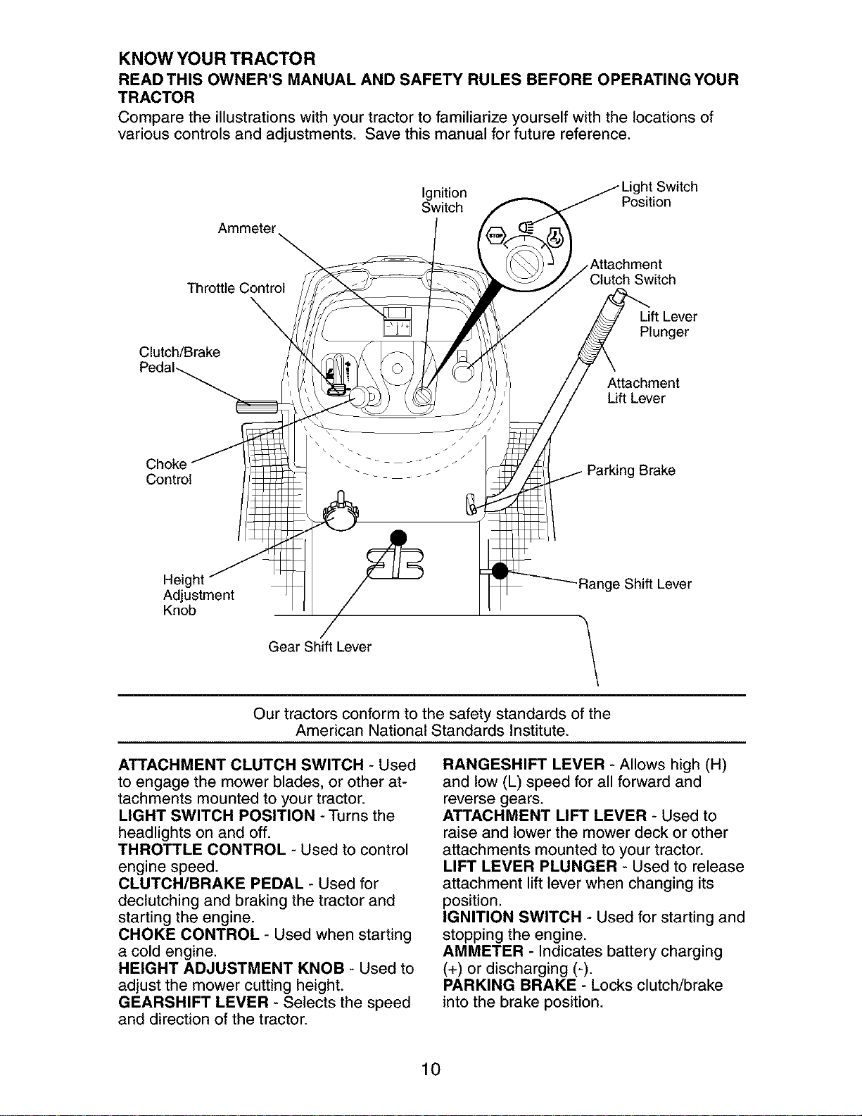
KNOW YOUR TRACTOR
READ THIS OWNER'S MANUAL AND SAFETY RULES BEFORE OPERATING YOUR
TRACTOR
Compare the illustrations with your tractor to familiarize yourself with the locations of
various controls and adjustments. Save this manual for future reference.
Ammeter
Ignition ht Switch
Switch Position
Throttle Control Clutch Switch
Lift Lever
Plunger
Clutch/Brake
Attachment
Lift Lever
Choke
Control
Brake
Height
Adjustment
Knob
Gear Shift Lever
Range Shift Lever
\
Our tractors conform to the safety standards of the
American National Standards Institute.
ATTACHMENT CLUTCH SWITCH - Used
to engage the mower blades, or other at-
tachments mounted to your tractor.
LIGHT SWITCH POSITION - Turns the
headlights on and off.
THROTTLE CONTROL - Used to control
engine speed.
CLUTCH/BRAKE PEDAL - Used for
declutching and braking the tractor and
starting the engine.
CHOKE CONTROL - Used when starting
a cold engine.
HEIGHT ADJUSTMENT KNOB - Used to
adjust the mower cutting height.
GEARSHIFT LEVER - Selects the speed
and direction of the tractor.
RANGESHIFT LEVER - Allows high (H)
and low (L) speed for all forward and
reverse gears.
ATTACHMENT LIFT LEVER - Used to
raise and lower the mower deck or other
attachments mounted to your tractor.
LIFT LEVER PLUNGER - Used to release
attachment lift lever when changing its
position.
IGNITION SWITCH - Used for starting and
stopping the engine.
AMMETER - Indicates battery charging
(+) or discharging (-).
PARKING BRAKE - Locks clutch/brake
into the brake position.
10
The operation of any tractor can result in foreign objects thrown into the
eyes, which can result in severe eye damage. Always wear safety glasses
or eye shields while operating your tractor or performing any adjustments
or repairs. We recommend standard safety glasses or a wide vision safety
mask worn over spectacles.
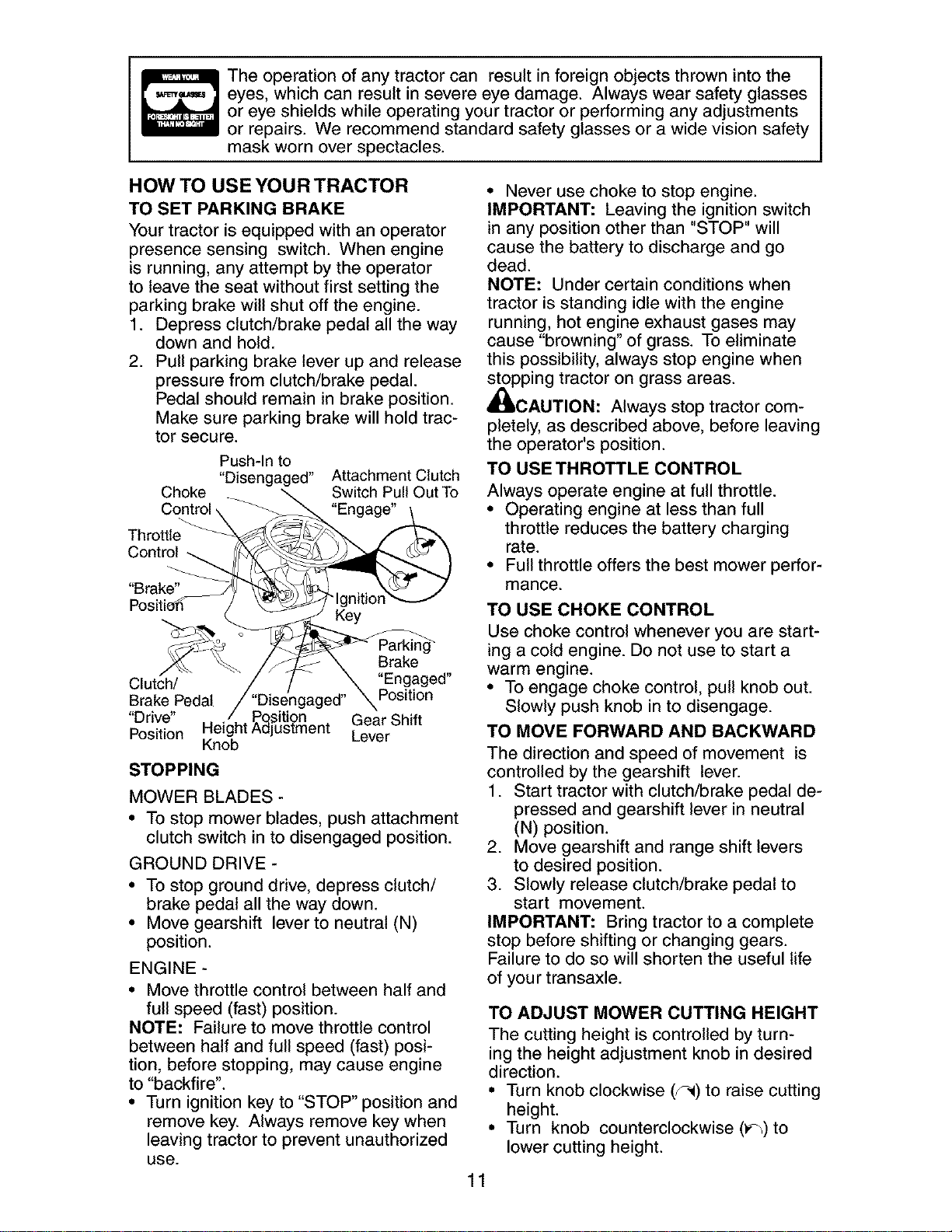
HOW TO USE YOUR TRACTOR
TO SET PARKING BRAKE
Your tractor is equipped with an operator
presence sensing switch. When engine
is running, any attempt by the operator
to leave the seat without first setting the
parking brake will shut off the engine.
1. Depress clutch/brake pedal all the way
down and hold.
2. Pull parking brake lever up and release
pressure from clutch/brake pedal.
Pedal should remain in brake position.
Make sure parking brake will hold trac-
tor secure.
Push-Into
"Disengaged"
Choke
Control
Throttle
Control
"Brake"
Attachment Clutch
Switch Pull Out To
"Engage"
Key
Brake
Clutch/ "Engaged"
Brake Pedal "Disengaged" Position
"Drive" , / Position Gear Shift
Position Height Adjustment Lever
Knob
STOPPING
MOWER BLADES -
• To stop mower blades, push attachment
clutch switch in to disengaged position.
GROUND DRIVE -
• To stop ground drive, depress clutch/
brake pedal all the way down.
• Move gearshift lever to neutral (N)
position.
ENGINE -
• Move throttle control between half and
full speed (fast) position.
NOTE: Failure to move throttle control
between half and full speed (fast) posi-
tion, before stopping, may cause engine
to "backfire".
• Turn ignition key to "STOP" position and
remove key. Always remove key when
leaving tractor to prevent unauthorized
use.
• Never use choke to stop engine.
IMPORTANT: Leaving the ignition switch
in any position other than "STOP" will
cause the battery to discharge and go
dead.
NOTE: Under certain conditions when
tractor is standing idle with the engine
running, hot engine exhaust gases may
cause "browning" of grass. To eliminate
this possibility, always stop engine when
stopping tractor on grass areas.
JlULCAUTION. Always stop tractor com-
pletely, as described above, before leaving
the operator's position.
TO USE THROTTLE CONTROL
Always operate engine at full throttle.
• Operating engine at less than full
throttle reduces the battery charging
rate.
• Full throttle offers the best mower perfor-
mance.
TO USE CHOKE CONTROL
Use choke control whenever you are start-
ing a cold engine. Do not use to start a
warm engine.
• To engage choke control, pull knob out.
Slowly push knob in to disengage.
TO MOVE FORWARD AND BACKWARD
The direction and speed of movement is
controlled by the gearshift lever.
1. Start tractor with clutch/brake pedal de-
pressed and gearshift lever in neutral
(N) position.
2. Move gearshift and range shift levers
to desired position.
3. Slowly release clutch/brake pedal to
start movement.
IMPORTANT: Bring tractor to a complete
stop before shifting or changing gears.
Failure to do so will shorten the useful life
of your transaxle.
TO ADJUST MOWER CUTTING HEIGHT
The cutting height is controlled by turn-
ing the height adjustment knob in desired
direction.
• Turn knob clockwise (J_) to raise cutting
height.
• Turn knob counterclockwise (v_)to
lower cutting height.
11
The cutting height range is approximately
1-1/2" to 4-1/2". The heights are mea-
sured from the ground to the blade tip with
the engine not running. These heights
are approximate and may vary depending
upon soil conditions, height of grass and
types of grass being mowed.
• The average lawn should be cut to
approximately 2-1/2 inches during the
cool season and to over 3 inches during
hot months. For healthier and better
looking lawns, mow often and after
moderate growth.
• For best cutting performance, grass over
6 inches in height should be mowed
twice. Make the first cut relatively high;
the second to desired height.
TO ADJUST GAUGE WHEELS
Gauge wheels are properly adjusted
when they are slightly off the ground when
mower is at the desired cutting height in
operating position. Gauge wheels then
keep the deck in proper position to help
prevent scalping in most terrain conditions.
NOTE: Be sure tractor is on a flat level
surface.
1. Lower mower and adjust mower to de-
sired cutting height(See "TO ADJUST
MOWER CUTTING HEIGHT' in this
section of manual).
2. Remove retainer spring and clevis pin
which secure each gauge wheel bar.
3. Lower gauge wheels to ground. Raise
gauge wheels slightly to align holes
in bracket and gauge wheel bar and
insert clevis pin. Gauge wheels should
be slightly off the ground.
4. Replace retainer spring into clevis pin.
5. Be sure all gauge wheels are in the
same setting.
IMPORTANT: Be sure to readjust gauge
wheels if you change the cutting height
of the mower deck.
Retainer
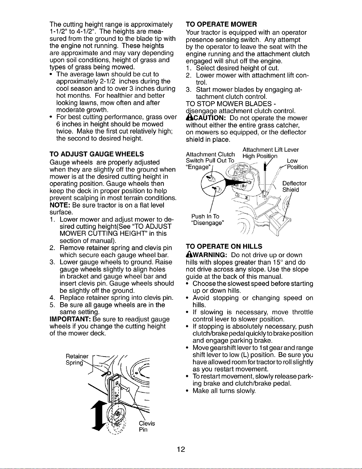
TO OPERATE MOWER
Your tractor is equipped with an operator
presence sensing switch. Any attempt
by the operator to leave the seat with the
engine running and the attachment clutch
engaged will shut off the engine.
1. Select desired height of cut.
2. Lower mower with attachment lift con-
trol.
3. Start mower blades by engaging at-
tachment clutch control.
TO STOP MOWER BLADES -
_iScengage attachment clutch control.
AUTION: Do not operate the mower
without either the entire grass catcher,
on mowers so equipped, or the deflector
shield in place.
Attachment Lift Lever
Attachment Clutch High Position
Switch Pull Out To o / Low
"Enga_ _/ /,S_"Position//
_; _,,;)_ Deflector
_" "_t_.i _ \_S" Shield
T
Push In To ;_-_..__
"Disengage" _) )_
TO OPERATE ON HILLS
_iLWARNING: Do not drive up or down
hills with slopes greater than 15° and do
not drive across any slope. Use the slope
guide at the back of this manual.
• Choose the slowest speed before starting
up or down hills.
• Avoid stopping or changing speed on
hills.
• If slowing is necessary, move throttle
control lever to slower position.
• If stopping is absolutely necessary, push
clutch/brake pedal quickly to brake position
and engage parking brake.
• Move gearshift lever to 1st gear and range
shift lever to low (L) position. Be sure you
have allowed room for tractor to roll slightly
as you restart movement.
• To restart movement, slowly release park-
ing brake and clutch/brake pedal.
• Make all turns slowly.
Clevis
Pin
12
TO TRANSPORT
• Raise attachment lift to highest position
with attachment lift control.
• When pushing or towing your tractor,
be sure gearshift lever is in neutral (N)
position.
• Do not push or tow tractor at more than
five (5) MPH.
NOTE: To protect hood from damage
when transporting your tractor on a truck
or a trailer, be sure hood is closed and
secured to tractor. Use an appropriate
means of tying hood to tractor (rope, cord,
etc.).
TOWING CARTS AND OTHER ATTACH-
MENTS
Tow only the attachments that are recom-
mended by and comply with specifications
of the manufacturer of your tractor. Use
common sense when towing. Too heavy
of a load, while on a slope, is dangerous.
Tires can lose traction with the ground and
cause you to lose control of your tractor.
BEFORE STARTING THE ENGINE
CHECK ENGINE OIL LEVEL
The engine in your tractor has been
shipped, from the factory, already filled
with summer weight oil.
1. Check engine oil with tractor on level
ground.
2. Unthread and remove oil fill cap/
dipstick; wipe oil off. Reinsert the
dipstick into the tube and rest oil fill
cap on the tube. Do not thread the cap
onto the tube. Remove and read oil
level. If necessary, add oil until "FULL'
mark on dipstick is reached. Do not
overfill.
• For cold weather operation you should
change oil for easier starting (See "OIL
VISCOSITY CHART" in the Mainte-
nance section of this manual).
• To change engine oil, see the Mainte-
nance section in this manual.
ADD GASOLINE
• Fill fuel tank to bottom of filler neck. Do
not overfill. Use fresh, clean, regular
unleaded gasoline with a minimum of
87 octane. (Use of leaded gasoline will
increase carbon and lead oxide deposits
and reduce valve life). Do not mix oil
with gasoline. Purchase fuel in quan-
tities that can be used within 30 days to
assure fuel freshness.
_I,CAUTION: Wipe off any spilled oil or
fuel. Do not store, spill or use gasoline
near an open flame.
IMPORTANT: When operating in temper-
atures below32°F(0°C), use fresh, clean
winter grade gasoline to help insure good
cold weather starting.
CAUTION: Alcohol blended fuels (called
gasohol or using ethanol or methanol) can
attract moisture which leads to separa-
tion and formation of acids during storage.
Acidic gas can damage the fuel system
of an engine while in storage. To avoid
engine problems, the fuel system should
be emptied before storage of 30 days
or longer. Drain the gas tank, start the
engine and let it run until the fuel lines
and carburetor are empty. Use fresh fuel
next season. See Storage Instructions for
additional information. Never use engine
or carburetor cleaner products in the fuel
tank or permanent damage may occur.
TO START ENGINE
When starting the engine for the first time
or if the engine has run out of fuel, it will
take extra cranking time to move fuel from
the tank to the engine.
1. Sit on seat in operating position,
depress clutch/brake pedal and set
parking brake.
2. Place gear shift lever in neutral (N)
position.
3. Move attachment clutch to disengaged
position.
4. Move throttle control to fast position
5. Pull choke control out for a cold engine
start attempt. For a warm engine start
attempt the choke control may not be
needed.
NOTE: Before starting, read the warm and
cold starting procedures below.
6. Insert key into ignition and turn key
clockwise to start position and release
key as soon as engine starts. Do
not run starter continuously for more
than fifteen seconds per minute. If the
engine does not start after several
attempts, push choke control in, wait
a few minutes and try again. If engine
still does not start, pull the choke con-
trol out and retry.
WARM WEATHER STARTING (50 ° F and
above)
7. When engine starts, slowly push choke
control in until the engine begins to
run smoothly. If the engine starts to
run roughly, pull the choke control out
slightly for a few seconds and then
continue to push the control in slowly.
13
• The attachments and ground drive can
now be used. If the engine does not
accept the load, restart the engine and
allow it to warm up for one minute using
the choke as described above.
COLD WEATHER STARTING (50° F and
below)
7. When engine starts, slowly push choke
control in until the engine begins to run
smoothly. Continue to push the choke
control in small steps allowing the en-
gine to accept small changes in speed
and load, until the choke control is fully
in. If the engine starts to run roughly,
pull the choke control out slightly for a
few seconds and then continue to push
the control in slowly. This may require
an engine warm-up period from several
seconds to several minutes, depending
on the temperature.
• The attachments can be used during
the engine warm-up period and may
require the choke control be pulled out
slightly.
NOTE: If at a high altitude (above 3000
feet) or in cold temperatures (below 32 F)
the carburetor fuel mixture may need to
be adjusted for best engine performance.
See "TO ADJUST CARBURETOR" in the
Service and Adjustments section of this
manual.
MOWING TIPS
• Tire chains cannot be used when the
mower housing is attached to tractor.
• Mower should be properly leveled for
best mowing performance. See "TO
LEVEL MOWER HOUSING" in the
Service and Adjustments section of this
manual.
• The left hand side of mower should be
used for trimming.
• Drive so that clippings are discharged
onto the area that has already been
cut. Have the cut area to the right of
the tractor. This will result in a more
even distribution of clippings and more
uniform cutting.
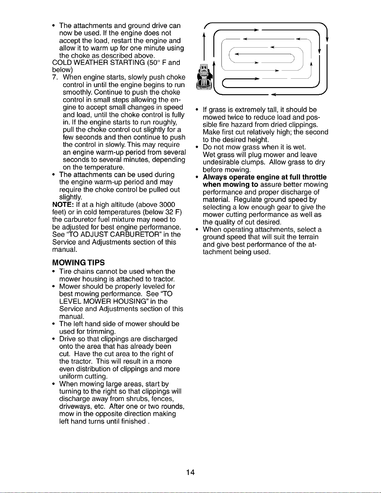
• When mowing large areas, start by
turning to the right so that clippings will
discharge away from shrubs, fences,
driveways, etc. After one or two rounds,
mow in the opposite direction making
left hand turns until finished.
f
1
f
f
C
- J
• If grass is extremely tall, it should be
mowed twice to reduce load and pos-
sible fire hazard from dried clippings.
Make first cut relatively high; the second
to the desired height.
• Do not mow grass when it is wet.
Wet grass will plug mower and leave
undesirable clumps. Allow grass to dry
before mowing.
• Always operate engine at full throttle
when mowing to assure better mowing
performance and proper discharge of
material. Regulate ground speed by
selecting a low enough gear to give the
mower cutting performance as well as
the quality of cut desired.
• When operating attachments, select a
ground speed that will suit the terrain
and give best performance of the at-
tachment being used.
14
MAINTENANCE SCHEDULE ._*_ ,_ ,_-_ _ _. ,_/_
AS YOU COMPLETE
REGO 'RSERV,CE OATES
Chh:: kkTB_raek;,eOsPe_:i°n _
Check Operator Presence and
t Interlock Systems
R Check for Loose Fasteners
Sharpen/Replace Mower Blades
t Lubrication Chart
0 Check Battery Level
R C_ean Battery and Terminals
Check Transaxle Cooling
Check WBefts
Check Engine Oil Level
Change Engine Oil (with oil filter)
E Change Engine Oil (without oil filter)
N Clean Air Filter
(_ Clean Air Screen
Inspect Muffter/Spark Attester
E Replace Oil Filter (If equipped)
Clean Engine Cooling Fins
Replace Spark Plug
Replace Air Filter Paper Cartridge
Replace Fuel Filter
v'
v'
1 - Change more often when operating under a heavy load or
in high ambient temperatures.
2 _ Service more otten when operating in di_ty or dusty conditions.
3 - Replace blades more often when mowing in sandy soil
4 - Not required if equipped with maintenance-free battery.
5 - Tighten front axle pivot bolt to 35 ft.=tbs, maximum.
Do not ovedighten.
GENERAL RECOMMENDATIONS
The warranty on this tractor does not
cover items that have been subjected to
operator abuse or negligence. To receive
full value from the warranty, operator
must maintain tractor as instructed in this
manual.
Some adjustments will need to be made
periodically to properly maintain your
tractor.
At least once a season, check to see if
you should make any of the adjustments
described in the Service and Adjustments
section of this manual.
• At least once a year you should replace
the spark plug, clean or replace air filter,
and check blades and belts for wear.
A new spark plug and clean air filter
assure proper air-fuel mixture and help
your engine run better and last longer.
BEFORE EACH USE
f. Check engine oil level.
2. Check brake operation.
3. Check tire pressure.
4. Check operator presence and
interlock systems for proper operation.
5. Check for loose fasteners.
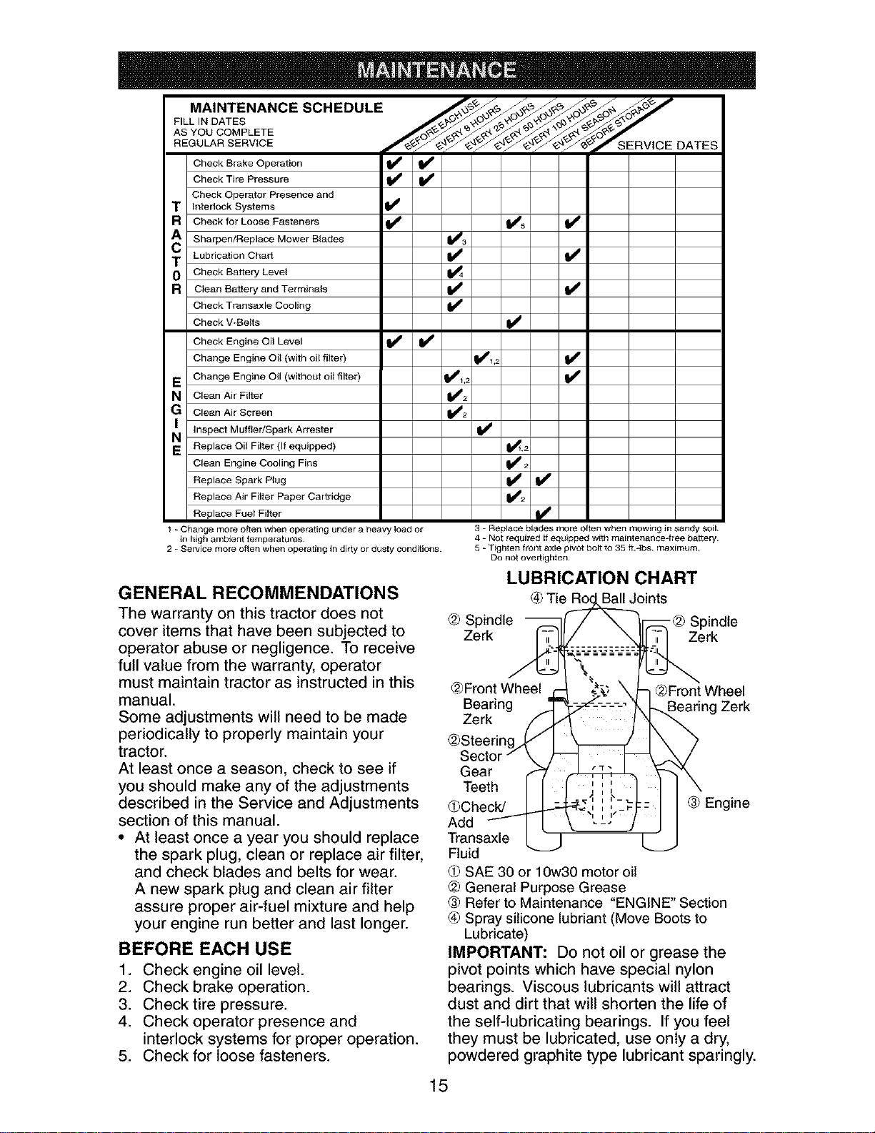
LUBRICATION CHART
Ball Joints
@ Spindle -@ Spindle
Zerk Zerk
@Front Wheel @Front Wheel
Bearing Zerk
Zerk
@Steerin(
Sector
Gear
Teeth
(#Check/ ® Engine
Add
Transaxle
Fluid
SAE 30 or 10w30 motor oil
@ General Purpose Grease
® Refer to Maintenance "ENGINE" Section
(_ Spray silicone lubriant (Move Boots to
Lubricate)
IMPORTANT: Do not oil or grease the
pivot points which have special nylon
bearings. Viscous lubricants will attract
dust and dirt that will shorten the life of
the self-lubricating bearings. If you feel
they must be lubricated, use only a dry,
powdered graphite type lubricant sparingly.
15
TRACTOR
Always observe safety rules when per-
forming any maintenance.
BRAKE OPERATION
If tractor requires more than six (6) feet
stopping distance at high speed in highest
gear, then brake must be adjusted. (See
"TO ADJUST BRAKE" in the Service and
Adjustments section of this manual).
TIRES
• Maintain proper air pressure in all tires
(See "PRODUCT SPECIFICATIONS"
section of this manual).
• Keep tires free of gasoline, oil, or insect
control chemicals which can harm rub-
ber.
• Avoid stumps, stones, deep ruts, sharp
objects and other hazards that may
cause tire damage.
NOTE: To seal tire punctures and prevent
flat tires due to slow leaks, tire sealant
may be purchased from your local parts
dealer. Tire sealant also prevents tire dry
rot and corrosion.
OPERATOR PRESENCE SYSTEM
Be sure operator presence and interlock
systems are working properly. If your trac-
tor does not function as described, repair
the problem immediately.
• The engine should not start unless
the brake pedal is fully depressed and
attachement clutch control is in the
disengaged position.
• When the engine is running, any at-
tempt by the operator to leave the seat
without first setting the parking brake
should shut off the engine.
• When the engine is running and the
attachment clutch is engaged, any at-
tempt by the operator to leave the seat
should shut off the engine.
• The attachment clutch should never op-
erate unless the operator is in the seat.
BLADE CARE
For best results mower blades must be
kept sharp. Replace bent or damaged
blades.
BLADE REMOVAL
1. Raise mower to highest position to al-
low access to blades.
NOTE: Protect your hands with gloves
and/or wrap blade with heavy cloth.
2. Remove blade bolt by turning counter-
clockwise.
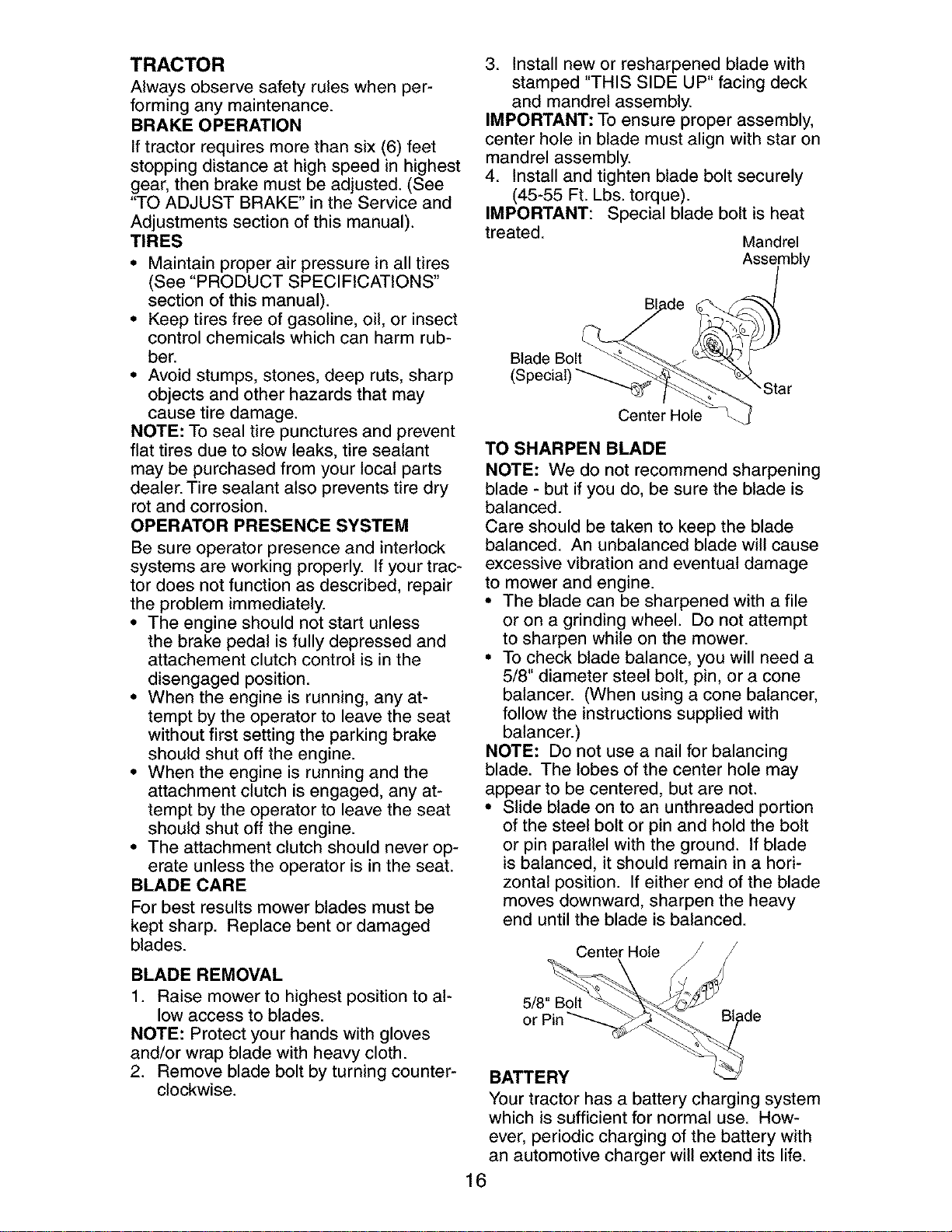
3. Install new or resharpened blade with
stamped "THIS SIDE UP" facing deck
and mandrel assembly.
IMPORTANT: To ensure proper assembly,
center hole in blade must align with star on
mandrel assembly.
4. Install and tighten blade bolt securely
(45-55 Ft. Lbs. torque).
IMPORTANT: Special blade bolt is heat
treated.
Mandrel
Assembly
Blade
"Star
Center Hole
TO SHARPEN BLADE
NOTE: We do not recommend sharpening
blade - but if you do, be sure the blade is
balanced.
Care should be taken to keep the blade
balanced. An unbalanced blade will cause
excessive vibration and eventual damage
to mower and engine.
• The blade can be sharpened with a file
or on a grinding wheel. Do not attempt
to sharpen while on the mower.
• To check blade balance, you will need a
5/8" diameter steel bolt, pin, or a cone
balancer. (When using a cone balancer,
follow the instructions supplied with
balancer.)
NOTE: Do not use a nail for balancing
blade. The lobes of the center hole may
appear to be centered, but are not.
• Slide blade on to an unthreaded portion
of the steel bolt or pin and hold the bolt
or pin parallel with the ground. If blade
is balanced, it should remain in a hori-
zontal position. If either end of the blade
moves downward, sharpen the heavy
end until the blade is balanced.
Center Hole
5/8" Bolt
or
BATTERY
Your tractor has a battery charging system
which is sufficient for normal use. How-
ever, periodic charging of the battery with
an automotive charger will extend its life.
16
• Keep battery and terminals clean.
• Keep battery bolts tight.
• Keep small vent holes open.
• Recharge at 6-10 amperes for 1 hour.
NOTE: The original equipment battery on
your tractor is maintenance free. Do not
attempt to open or remove caps or covers.
Adding or checking level of electrolyte is
not necessary.
TO CLEAN BATTERY AND TERMINALS
Corrosion and dirt on the battery and
terminals can cause the battery to "leak"
power.
1. Remove terminal guard.
2. Disconnect BLACK battery cable first
then RED battery cable and remove
battery from tractor.
3. Rinse the battery with plain water and
dry.
4. Clean terminals and battery cable ends
with wire brush until bright.
5. Coat terminals with grease or petro-
leum jelly.
6. Reinstall battery (See "REPLACING
BATTERY" in the SERVICE AND AD-
JUSTMENTS section of this manual).
TRANSAXLE COOLING
Keep transaxle free from build-up of dirt
and chaff which can restrict cooling.
CHECKTRANSAXLE OIL LEVEL
1. Block up rear axle securely.
2. Remove left rear wheel by removing
hub bolts.
3. Remove filler plug from transaxle. Oil
level must be even with plug threads.
If necessary, fill with SAE 30 motor oil,
API SF-SJ. Replace filler plug.
4. Reassemble wheel to hub.
V-BELTS
Transaxle Filler
Plug
Check V-belts for deterioration and wear
after 100 hours of operation and replace
if necessary. The belts are not adjustable.
Replace belts if they begin to slip from
wear.
ENGINE
LUBRICATION
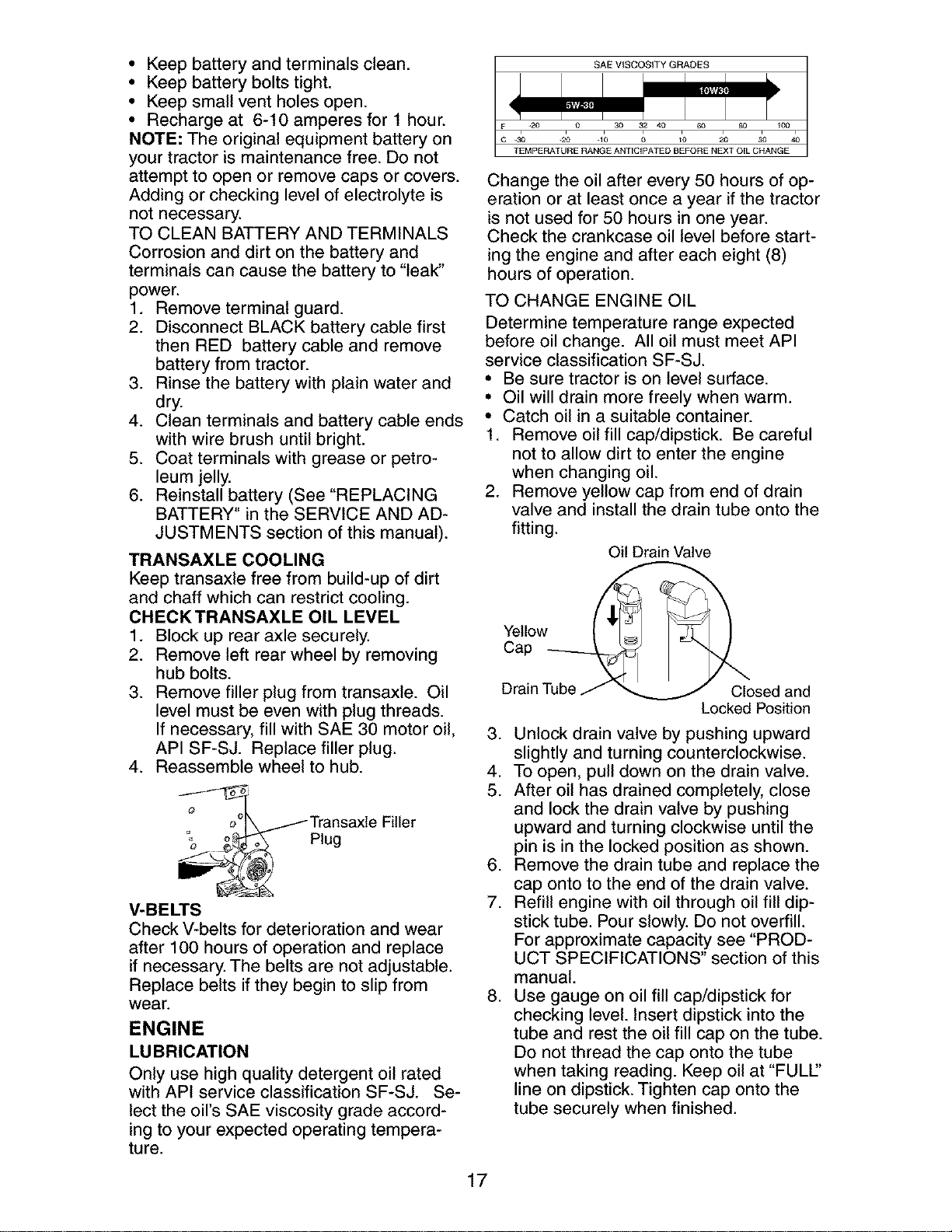
Only use high quality detergent oil rated
with API service classification SF-SJ. Se-
lect the oil's SAE viscosity grade accord-
ing to your expected operating tempera-
ture.
SAE VISCOSITY GRADES
T_MPE RAT& E AANG°EANT,C,OATED B_FORE N2OT O,L C_ANGE
Change the oil after every 50 hours of op-
eration or at least once a year if the tractor
is not used for 50 hours in one year.
Check the crankcase oil level before start-
ing the engine and after each eight (8)
hours of operation.
TO CHANGE ENGINE OIL
Determine temperature range expected
before oil change. All oil must meet API
service classification SF-SJ.
• Be sure tractor is on level surface.
• Oil will drain more freely when warm.
• Catch oil in a suitable container.
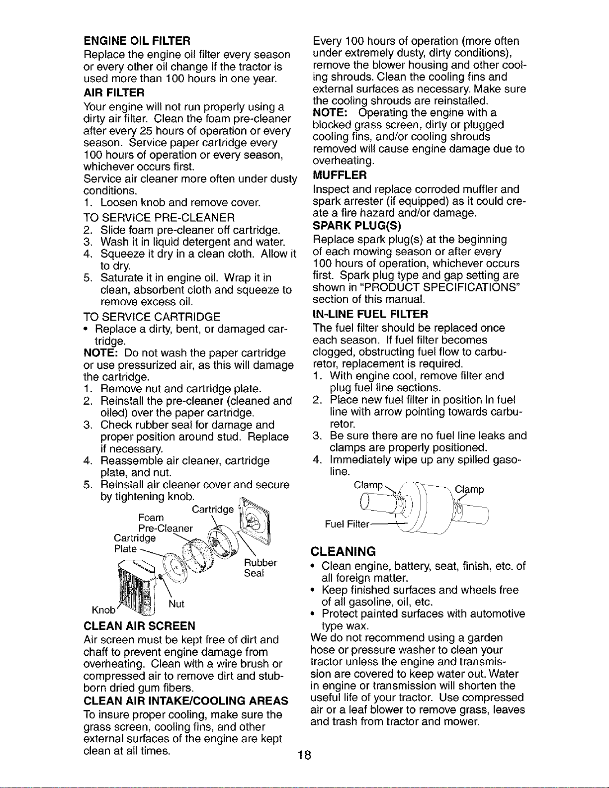
1. Remove oil fill cap/dipstick. Be careful
not to allow dirt to enter the engine
when changing oil.
2. Remove yellow cap from end of drain
valve and install the drain tube onto the
fitting.
Oil Drain Valve
Yellow
Cap
Drain Tube Closed and
Locked Position
3. Unlock drain valve by pushing upward
slightly and turning counterclockwise.
4. To open, pull down on the drain valve.
5. After oil has drained completely, close
and lock the drain valve by pushing
upward and turning clockwise until the
pin is in the locked position as shown.
6. Remove the drain tube and replace the
cap onto to the end of the drain valve.
7. Refill engine with oil through oil fill dip-
stick tube. Pour slowly. Do not overfill.
For approximate capacity see "PROD-
UCT SPECIFICATIONS" section of this
manual.
8. Use gauge on oil fill cap/dipstick for
checking level. Insert dipstick into the
tube and rest the oil fill cap on the tube.
Do not thread the cap onto the tube
when taking reading. Keep oil at "FULl"
line on dipstick. Tighten cap onto the
tube securely when finished.
17
ENGINE OIL FILTER
Replace the engine oil filter every season
or every other oil change if the tractor is
used more than 100 hours in one year.
AIR FILTER
Your engine will not run properly using a
dirty air filter. Clean the foam pre-cleaner
after every 25 hours of operation or every
season. Service paper cartridge every
100 hours of operation or every season,
whichever occurs first.
Service air cleaner more often under dusty
conditions.
1. Loosen knob and remove cover.
TO SERVICE PRE-CLEANER
2. Slide foam pre-cleaner off cartridge.
3. Wash it in liquid detergent and water.
4. Squeeze it dry in a clean cloth. Allow it
to dry.
5. Saturate it in engine oil. Wrap it in
clean, absorbent cloth and squeeze to
remove excess oil.
TO SERVICE CARTRIDGE
• Replace a dirty, bent, or damaged car-
tridge.
NOTE: Do not wash the paper cartridge
or use pressurized air, as this will damage
the cartridge.
1. Remove nut and cartridge plate.
2. Reinstall the pre-cleaner (cleaned and
oiled) over the paper cartridge.
3. Check rubber seal for damage and
proper position around stud. Replace
if necessary.
4. Reassemble air cleaner, cartridge
plate, and nut.
5. Reinstall air cleaner cover and secure
by tightening knob.
Foam
Pre-Cleaner
Cartridge
Rubber
Seal
Nut
Knob'
CLEAN AIR SCREEN
Air screen must be kept free of dirt and
chaff to prevent engine damage from
overheating. Clean with a wire brush or
compressed air to remove dirt and stub-
born dried gum fibers.
CLEAN AIR INTAKE/COOLING AREAS
To insure proper cooling, make sure the
grass screen, cooling fins, and other
external surfaces of the engine are kept
clean at all times.
Every 100 hours of operation (more often
under extremely dusty, dirty conditions),
remove the blower housing and other cool-
ing shrouds. Clean the cooling fins and
external surfaces as necessary. Make sure
the cooling shrouds are reinstalled.
NOTE: Operating the engine with a
blocked grass screen, dirty or plugged
cooling fins, and/or cooling shrouds
removed will cause engine damage due to
overheating.
MUFFLER
Inspect and replace corroded muffler and
spark arrester (if equipped) as it could cre-
ate a fire hazard and/or damage.
SPARK PLUG(S)
Replace spark plug(s) at the beginning
of each mowing season or after every
100 hours of operation, whichever occurs
first. Spark plug type and gap setting are
shown in "PRODUCT SPECIFICATIONS"
section of this manual.
IN-LINE FUEL FILTER
The fuel filter should be replaced once
each season. If fuel filter becomes
clogged, obstructing fuel flow to carbu-
retor, replacement is required.
1. With engine cool, remove filter and
plug fuel line sections.
2. Place new fuel filter in position in fuel
line with arrow pointing towards carbu-
retor.
3. Be sure there are no fuel line leaks and
clamps are properly positioned.
4. Immediately wipe up any spilled gaso-
line.
Fuel Filter_
CLEANING
• Clean engine, battery, seat, finish, etc. of
all foreign matter.
• Keep finished surfaces and wheels free
of all gasoline, oil, etc.
• Protect painted surfaces with automotive
type wax.
We do not recommend using a garden
hose or pressure washer to clean your
tractor unless the engine and transmis-
sion are covered to keep water out. Water
in engine or transmission will shorten the
useful life of your tractor. Use compressed
air or a leaf blower to remove grass, leaves
and trash from tractor and mower.
18
WARNING: TO AVOID SERIOUS INJURY, BEFORE PERFORMING ANY SER-
VICE OR ADJUSTMENTS:
1. Depress clutch/brake pedal fully and set parking brake.
2. Place gearshift lever in neutral (N) position.
3. Place attachment clutch in "DISENGAGED" position.
4. Turn ignition key to "STOP" and remove key.
5. Make sure the blades and all moving parts have completely stopped.
6. Disconnect spark plug wire from spark plug and place wire where it cannot
come in contact with plug.
TRACTOR
TO REMOVE MOWER
1. Place attachment clutch in "DISEN-
GAGED" position.
2. If equipped, turn height adjustment
knob to lowest setting.
3. Lower mower to its lowest position.
4. Remove retainer spring holding
anti-sway bar to chassis bracket and
disengage anti-sway bar from bracket.
5. Remove four retainer springs from front
plate assembly and remove plate.
6. Remove retainer springs from suspen-
sion arms at deck and disengage arms
from deck.
7. Raise attachment lift to its highest posi-
tion.
8. Slide mower forward and remove belt
from electric clutch pulley.
9. Slide mower out from under right side
of tractor.
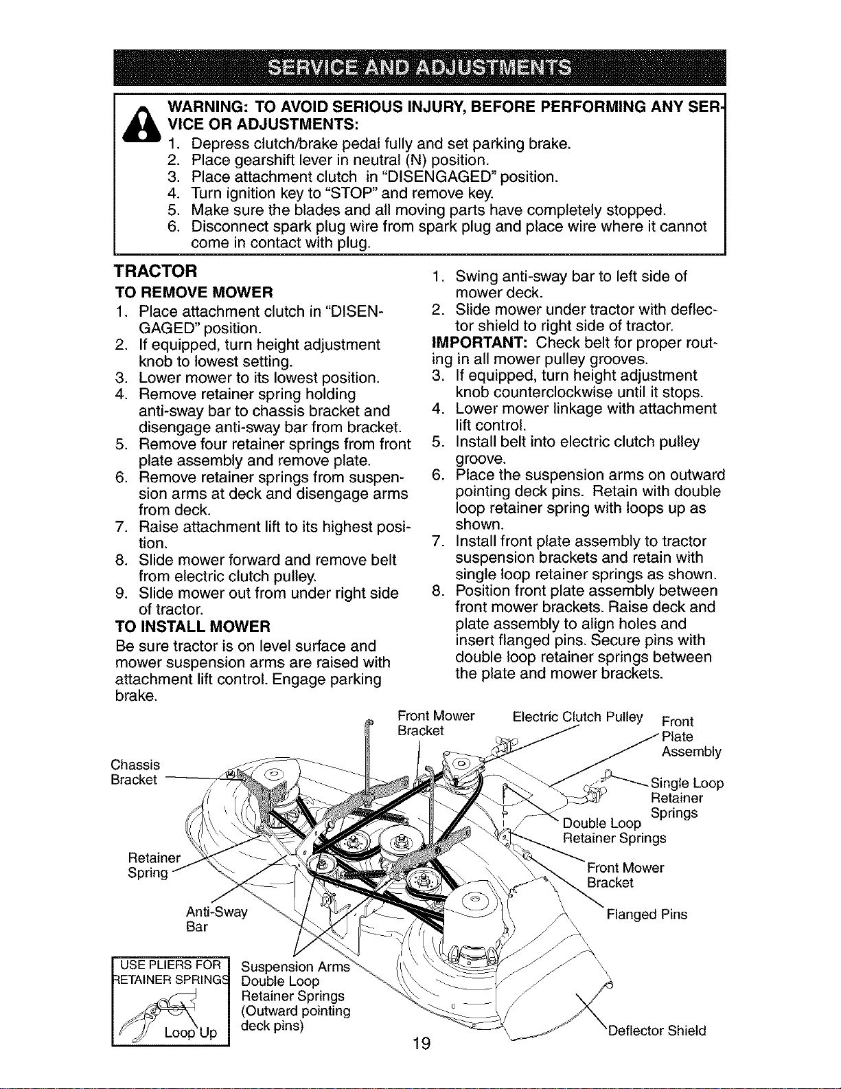
TO INSTALL MOWER
Be sure tractor is on level surface and
mower suspension arms are raised with
attachment lift control. Engage parking
brake.
Chassis
Bracket
Retainer
Spring
1. Swing anti-sway bar to left side of
mower deck.
2. Slide mower under tractor with deflec-
tor shield to right side of tractor.
IMPORTANT: Check belt for proper rout-
ing in all mower pulley grooves.
3. If equipped, turn height adjustment
knob counterclockwise until it stops.
4. Lower mower linkage with attachment
lift control.
5. Install belt into electric clutch pulley
greeve.
6. Place the suspension arms on outward
pointing deck pins. Retain with double
loop retainer spring with loops up as
shown.
7. Install front plate assembly to tractor
suspension brackets and retain with
single loop retainer springs as shown.
8. Position front plate assembly between
front mower brackets. Raise deck and
plate assembly to align holes and
insert flanged pins. Secure pins with
double loop retainer springs between
the plate and mower brackets.
Front Mower Electric Clutch Pulley Front
Bracket
Assembly
_""---_ Single Loop
Retainer
Springs
Double Loop
Retainer Springs
Bracket
Anti-Sway
Bar
Flanged Pins
USE PLIERS FOR
:{ETAtNER SPRING_
Up
Suspension Arm_
Double Loop
Retainer Springs
(Outward pointing
deck pins)
19
'Deflector Shield
NOTE: To assist in locating hole in flanged
pin, the hole in pin is inline with notch on
head of pin. If necessary, move mower
side-to-side to give space between plate
and mower brackets.
IMPORTANT: Check belt for proper rout-
ing in all mower pulley grooves.
9. Connect anti-sway bar to chassis
bracket under left footrest and retain
with double loop retainer spring.
10. If equipped, turn height adjustment
knob clockwise to remove slack from
mower suspension.
11. Raise deck to highest position.
TO LEVEL MOWER HOUSING
Adjust the mower while tractor is parked
on level ground such as a carport or ga-
rage. Make sure tires are properly inflated
(See "PRODUCT SPECIFICATIONS"
section of this manual). If tires are over or
underinflated, you will not properly adjust
your mower.
SIDE-TO-SIDE ADJUSTMENT WITH
BUBBLE LEVEL
NOTE: If necessary, check side-to-side
surface below tractor for levelness with a
long board and the bubble level.
• Using the lift lever, place mower in
position where no part of the mower,
including gauge wheels, is touching the
ground.
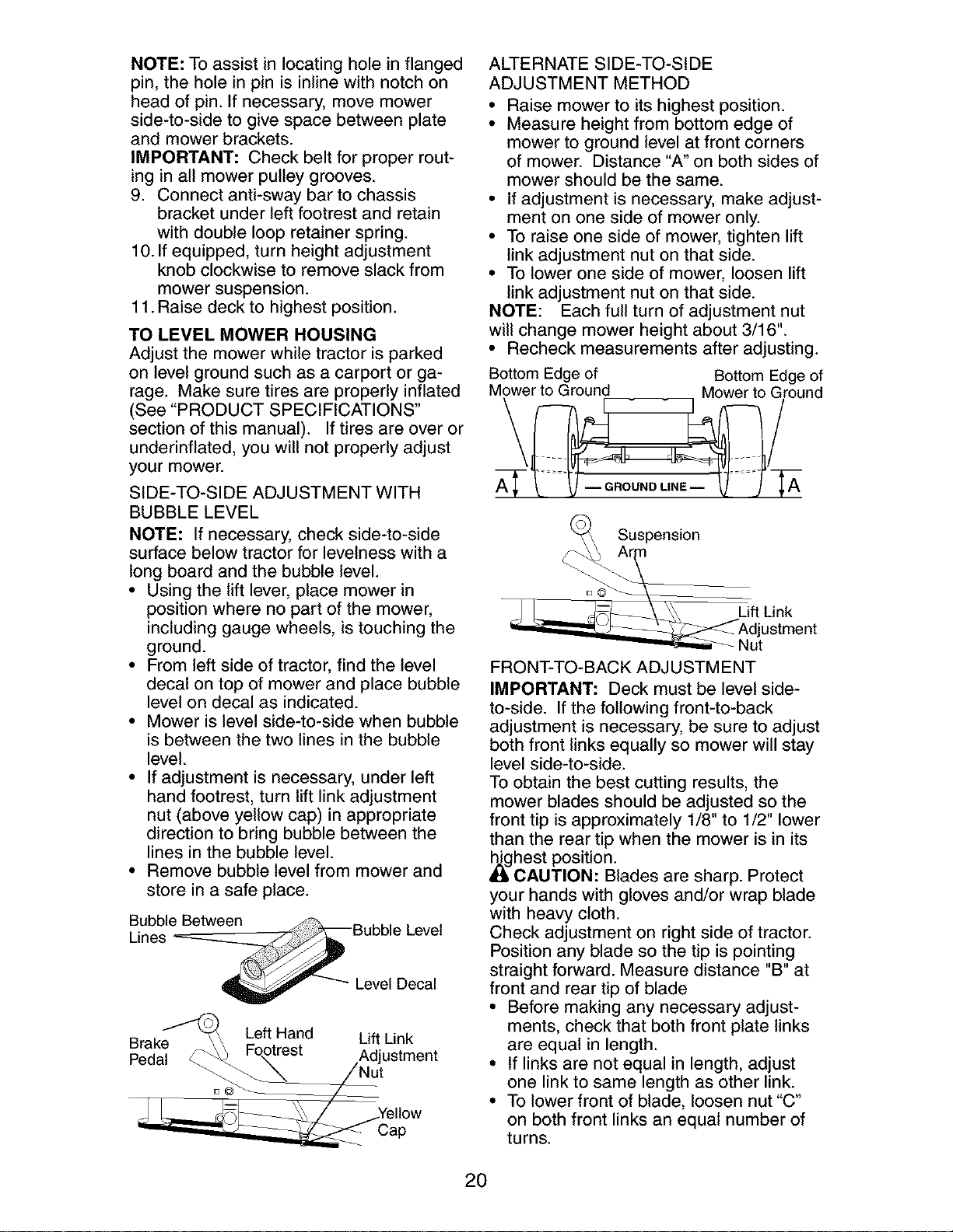
• From left side of tractor, find the level
decal on top of mower and place bubble
level on decal as indicated.
• Mower is level side-to-side when bubble
is between the two lines in the bubble
level.
• If adjustment is necessary, under left
hand footrest, turn lift link adjustment
nut (above yellow cap) in appropriate
direction to bring bubble between the
lines in the bubble level.
• Remove bubble level from mower and
store in a safe place.
Bubble Between
Lines
Level Decal
Brake_ Left Hand Lift Link
Pedal _ Fo,.otrest ,Adjustment
J e,Iow
Cap
ALTERNATE SIDE-TO-SIDE
ADJUSTMENT METHOD
• Raise mower to its highest position.
• Measure height from bottom edge of
mower to ground level at front corners
of mower. Distance "A" on both sides of
mower should be the same.
• If adjustment is necessary, make adjust-
ment on one side of mower only.
• To raise one side of mower, tighten lift
link adjustment nut on that side.
• To lower one side of mower, loosen lift
link adjustment nut on that side.
NOTE: Each full turn of adjustment nut
will change mower height about 3/16".
• Recheck measurements after adjusting.
Bottom Edge of Bottom Edge of
Mower to Ground Mower to Ground
Suspension
J jL ftLink
_ AdJtustment
FRONT-TO-BACK ADJUSTMENT
IMPORTANT: Deck must be level side-
to-side. If the following front-to-back
adjustment is necessary, be sure to adjust
both front links equally so mower will stay
level side-to-side.
To obtain the best cutting results, the
mower blades should be adjusted so the
front tip is approximately 1/8" to 1/2" lower
than the rear tip when the mower is in its
_ghest position.
CAUTION: Blades are sharp. Protect
your hands with gloves and/or wrap blade
with heavy cloth.
Check adjustment on right side of tractor.
Position any blade so the tip is pointing
straight forward. Measure distance "B" at
front and rear tip of blade
• Before making any necessary adjust-
ments, check that both front plate links
are equal in length.
• If links are not equal in length, adjust
one link to same length as other link.
• To lower front of blade, loosen nut "C"
on both front links an equal number of
turns.
20
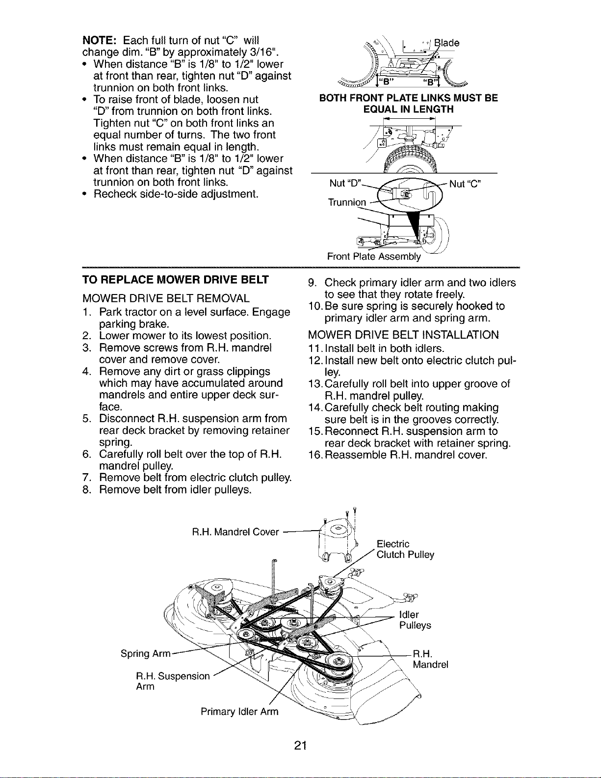
NOTE: Each full turn of nut "C" will
change dim. "B" by approximately 3/16".
• When distance "B" is 1/8" to 1/2" lower
at front than rear, tighten nut "D" against
trunnion on both front links.
• To raise front of blade, loosen nut
"D" from trunnion on both front links.
Tighten nut "C" on both front links an
equal number of turns. The two front
links must remain equal in length.
• When distance "B" is 1/8" to 1/2" lower
at front than rear, tighten nut "D" against
trunnion on both front links.
• Recheck side-to-side adjustment.
BOTH FRONT PLATE LINKS MUST BE
EQUAL IN LENGTH
Front Plate Assembl
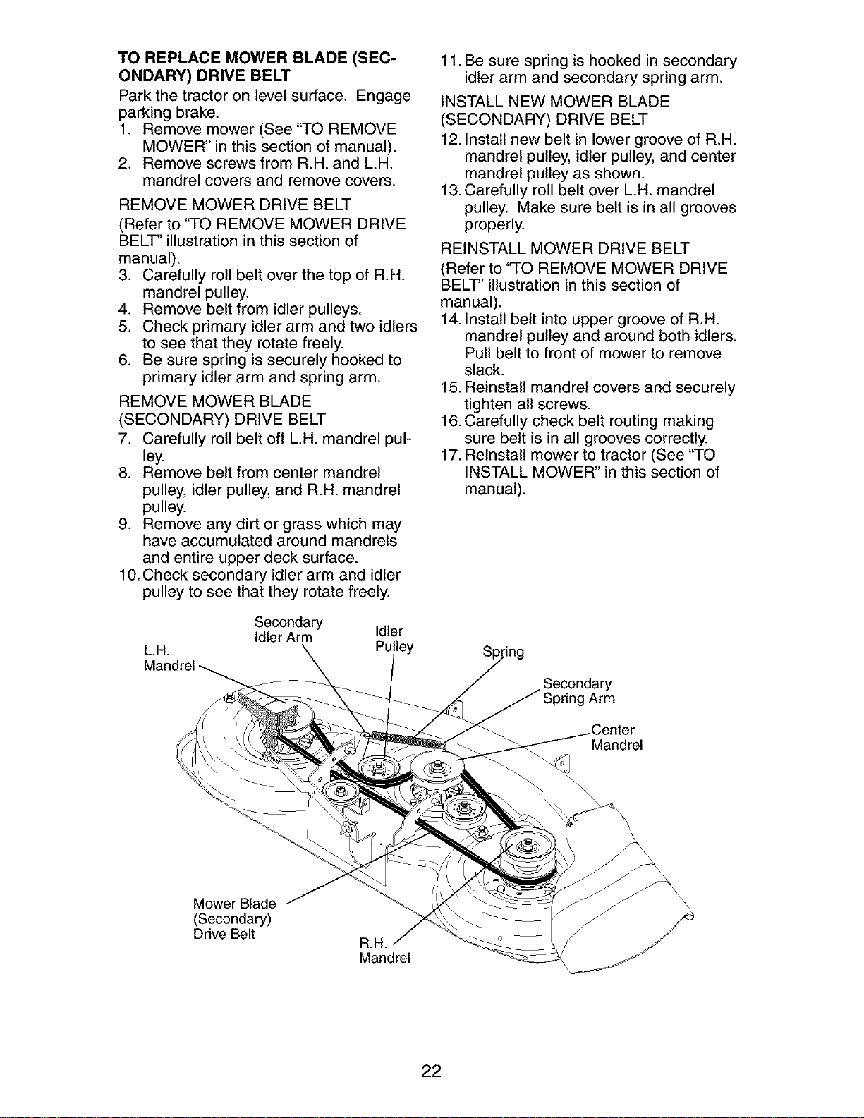
TO REPLACE MOWER DRIVE BELT
MOWER DRIVE BELT REMOVAL
1. Park tractor on a level surface. Engage
parking brake.
2. Lower mower to its lowest position.
3. Remove screws from R.H. mandrel
cover and remove cover.
4. Remove any dirt or grass clippings
which may have accumulated around
mandrels and entire upper deck sur-
face.
5. Disconnect R.H. suspension arm from
rear deck bracket by removing retainer
spring.
6. Carefully roll belt over the top of R.H.
mandrel pulley.
7. Remove belt from electric clutch pulley.
8. Remove belt from idler pulleys.
9. Check primary idler arm and two idlers
to see that they rotate freely.
10. Be sure spring is securely hooked to
primary idler arm and spring arm.
MOWER DRIVE BELT INSTALLATION
11. Install belt in both idlers.
12. Install new belt onto electric clutch pul-
ley.
13.Carefully roll belt into upper groove of
R.H. mandrel pulley.
14.Carefully check belt routing making
sure belt is in the grooves correctly.
15. Reconnect R.H. suspension arm to
rear deck bracket with retainer spring.
16. Reassemble R.H. mandrel cover.
R.H. Mandrel Cover
Electric
Pulley
Idler
Pulleys
Spring Arm.
R.H. Suspension
Arm
Mandrel
Primary Idler Arm
21
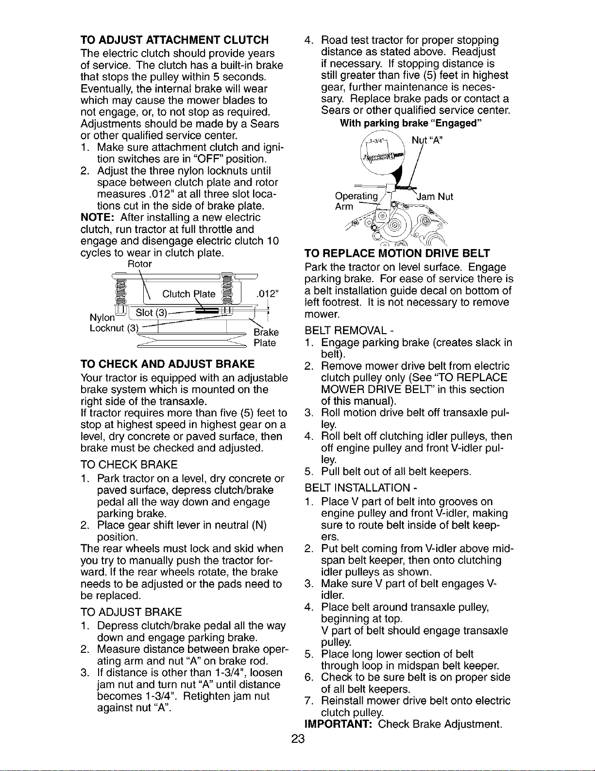
TO REPLACE MOWER BLADE (SEC-
ONDARY) DRIVE BELT
Park the tractor on level surface. Engage
parking brake.
1. Remove mower (See "TO REMOVE
MOWER" in this section of manual).
2. Remove screws from R.H. and L.H.
mandrel covers and remove covers.
REMOVE MOWER DRIVE BELT
(Refer to "TO REMOVE MOWER DRIVE
BELT" illustration in this section of
manual).
3. Carefully roll belt over the top of R.H.
mandrel pulley.
4. Remove belt from idler pulleys.
5. Check primary idler arm and two idlers
to see that they rotate freely.
6. Be sure spring is securely hooked to
primary idler arm and spring arm.
REMOVE MOWER BLADE
(SECONDARY) DRIVE BELT
7. Carefully roll belt off LH. mandrel pul-
ley.
8. Remove belt from center mandrel
pulley, idler pulley, and R.H. mandrel
pulley.
9. Remove any dirt or grass which may
have accumulated around mandrels
and entire upper deck surface.
10. Check secondary idler arm and idler
pulley to see that they rotate freely.
Secondary
Idler Arm Idler
L.H. Pulley
11. Be sure spring is hooked in secondary
idler arm and secondary spring arm.
INSTALL NEW MOWER BLADE
(SECONDARY) DRIVE BELT
12. Install new belt in lower groove of R.H.
mandrel pulley, idler pulley, and center
mandrel pulley as shown.
13.Carefully roll belt over L.H. mandrel
pulley. Make sure belt is in all grooves
properly.
REINSTALL MOWER DRIVE BELT
(Refer to "TO REMOVE MOWER DRIVE
BELT' illustration in this section of
manual).
14. Install belt into upper groove of R.H.
mandrel pulley and around both idlers.
Pull belt to front of mower to remove
slack.
15. Reinstall mandrel covers and securely
tighten all screws.
16. Carefully check belt routing making
sure belt is in all grooves correctly.
17. Reinstall mower to tractor (See "TO
INSTALL MOWER" in this section of
manual).
Secondary
Arm
Mandrel
Mower Blade
(Secondary)
Drive Belt
R.H.
Mandrel
\
22
TO ADJUST ATTACHMENT CLUTCH
The electric clutch should provide years
of service. The clutch has a built-in brake
that stops the pulley within 5 seconds.
Eventually, the internal brake will wear
which may cause the mower blades to
not engage, or, to not stop as required.
Adjustments should be made by a Sears
or other qualified service center.
1. Make sure attachment clutch and igni-
tion switches are in "OFF" position.
2. Adjust the three nylon Iocknuts until
space between clutch plate and rotor
measures .012"at all three slot loca-
tions cut in the side of brake plate.
NOTE: After installing a new electric
clutch, run tractor at full throttle and
engage and disengage electric clutch 10
cycles to wear in clutch plate.
Rotor
Clutch .012"
Ny
Locknut
_ Plate
TO CHECK AND ADJUST BRAKE
Your tractor is equipped with an adjustable
brake system which is mounted on the
right side of the transaxle.
If tractor requires more than five (5) feet to
stop at highest speed in highest gear on a
level, dry concrete or paved surface, then
brake must be checked and adjusted.
TO CHECK BRAKE
1. Park tractor on a level, dry concrete or
paved surface, depress clutch/brake
pedal all the way down and engage
parking brake.
2. Place gear shift lever in neutral (N)
position.
The rear wheels must lock and skid when
you try to manually push the tractor for-
ward. If the rear wheels rotate, the brake
needs to be adjusted or the pads need to
be replaced.
TO ADJUST BRAKE
1. Depress clutch/brake pedal all the way
down and engage parking brake.
2. Measure distance between brake oper-
ating arm and nut "A" on brake rod.
3. If distance is other than 1-3/4", loosen
jam nut and turn nut "A" until distance
becomes 1-3/4". Retighten jam nut
against nut "A".
4. Road test tractor for proper stopping
distance as stated above. Readjust
if necessary. If stopping distance is
still greater than five (5) feet in highest
gear, further maintenance is neces-
sary. Replace brake pads or contact a
Sears or other qualified service center.
With parking brake "Engaged"
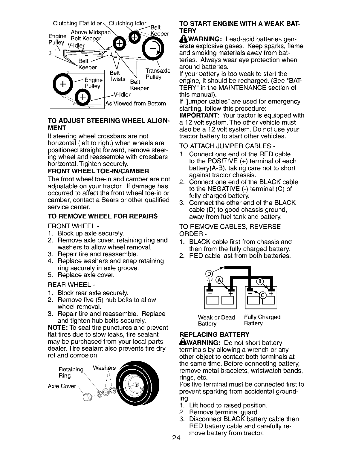
TO REPLACE MOTION DRIVE BELT
Park the tractor on level surface. Engage
parking brake. For ease of service there is
a belt installation guide decal on bottom of
left footrest. It is not necessary to remove
mower.
BELT REMOVAL -
1. Engage parking brake (creates slack in
belt).
2. Remove mower drive belt from electric
clutch pulley only (See "TO REPLACE
MOWER DRIVE BELT" in this section
of this manual).
3. Roll motion drive belt off transaxle pul-
ley.
4. Roll belt off clutching idler pulleys, then
off engine pulley and front V-idler pul-
ley.
5. Pull belt out of all belt keepers.
BELT INSTALLATION -
1. Place V part of belt into grooves on
engine pulley and front V-idler, making
sure to route belt inside of belt keep-
ers.
2. Put belt coming from V-idler above mid-
span belt keeper, then onto clutching
idler pulleys as shown.
3. Make sure V part of belt engages V-
idler.
4. Place belt around transaxle pulley,
beginning at top.
V part of belt should engage transaxle
pulley.
5. Place long lower section of belt
through loop in midspan belt keeper.
6. Check to be sure belt is on proper side
of all belt keepers.
7. Reinstall mower drive belt onto electric
clutch pulley.
IMPORTANT: Check Brake Adjustment.
23
Clutching Clutchim
Above Mids
Engine
Belt
Keeper _ .
B t Iransaxle
_- _e._ P II
• i _...i Engine I Twists Be t u ey
._Pulley I Keeper
"__.___./._ V-Idler
_As Viewed from Bottom
TO ADJUST STEERING WHEEL ALIGN-
MENT
If steering wheel crossbars are not
horizontal (left to right) when wheels are
positioned straight forward, remove steer-
ing wheel and reassemble with crossbars
horizontal. Tighten securely.
FRONT WHEEL TOE-IN/CAMBER
The front wheel toe-in and camber are not
adjustable on your tractor. If damage has
occurred to affect the front wheel toe-in or
camber, contact a Sears or other qualified
service center.
TO REMOVE WHEEL FOR REPAIRS
FRONT WHEEL -
1. Block up axle securely.
2. Remove axle cover, retaining ring and
washers to allow wheel removal.
3. Repair tire and reassemble.
4. Replace washers and snap retaining
ring securely in axle groove.
5. Replace axle cover.
REAR WHEEL-
1. Block rear axle securely.
2. Remove five (5) hub bolts to allow
wheel removal.
3. Repair tire and reassemble. Replace
and tighten hub bolts securely.
NOTE: To seal tire punctures and prevent
flat tires due to slow leaks, tire sealant
may be purchased from your local parts
dealer. Tire sealant also prevents tire dry
rot and corrosion.
Retaining Washers
Ring \
Axle Cover \
\
TO START ENGINE WITH AWEAK BAT-
TERY
_WARNING: Lead-acid batteries gen-
erate explosive gases. Keep sparks, flame
and smoking materials away from bat-
teries. Always wear eye protection when
around batteries.
If your battery is too weak to start the
engine, it should be recharged. (See "BAT-
TERY" in the MAINTENANCE section of
this manual).
If "jumper cables" are used for emergency
starting, follow this procedure:
IMPORTANT: Your tractor is equipped with
a 12 volt system. The other vehicle must
also be a 12 volt system. Do not use your
tractor battery to start other vehicles.
TO ATTACH JUMPER CABLES -
1. Connect one end of the RED cable
to the POSITIVE (+) terminal of each
battery(A-B), taking care not to short
against tractor chassis.
2. Connect one end of the BLACK cable
to the NEGATIVE (-) terminal (C) of
fully charged battery.
3. Connect the other end of the BLACK
cable (D) to good chassis ground,
away from fuel tank and battery.
TO REMOVE CABLES, REVERSE
ORDER -
1. BLACK cable first from chassis and
then from the fully charged battery.
2. RED cable last from both batteries.
Weak or Dead Fully Charged
Battery Battery
REPLACING BATTERY
_WARNING: Do not short battery
terminals by allowing a wrench or any
other object to contact both terminals at
the same time. Before connecting battery,
remove metal bracelets, wristwatch bands,
rings, etc.
Positive terminal must be connected first to
prevent sparking from accidental ground-
ing.
1. Lift hood to raised position.
2. Remove terminal guard.
3. Disconnect BLACK battery cable then
RED battery cable and carefully re-
move battery from tractor.
24
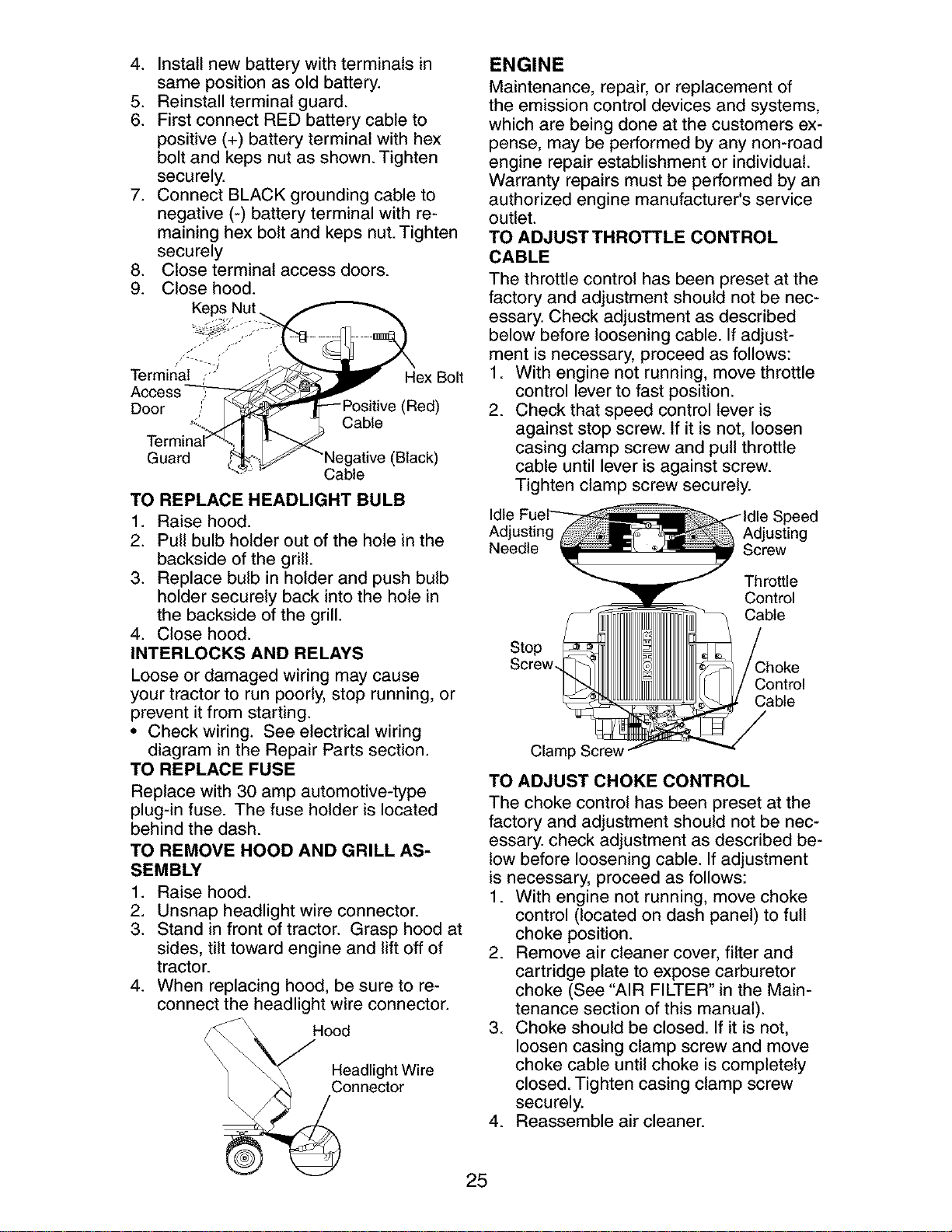
4. Installnewbatterywithterminalsin
samepositionasold battery.
5. Reinstallterminalguard.
6. FirstconnectREDbatterycableto
positive(+) batteryterminalwith hex
boltand kepsnutasshown.Tighten
securely.
7. ConnectBLACKgroundingcableto
negative(-)batteryterminalwith re-
maininghexboltand kepsnut.Tighten
securely
8. Closeterminalaccessdoors.
9. Closehood.
Door
Cable
Hex Bolt
(Red)
Guard (Black)
Cable
TO REPLACE HEADLIGHT BULB
1. Raise hood.
2. Pull bulb holder out of the hole in the
backside of the grill.
3. Replace bulb in holder and push bulb
holder securely back into the hole in
the backside of the grill.
4. Close hood.
INTERLOCKS AND RELAYS
Loose or damaged wiring may cause
your tractor to run poorly, stop running, or
prevent it from starting.
• Check wiring. See electrical wiring
diagram in the Repair Parts section.
TO REPLACE FUSE
Replace with 30 amp automotive-type
plug-in fuse. The fuse holder is located
behind the dash.
TO REMOVE HOOD AND GRILL AS-
SEMBLY
=
2.
3.
4_
Raise hood.
Unsnap headlight wire connector.
Stand in front of tractor. Grasp hood at
sides, tilt toward engine and lift off of
tractor.
When replacing hood, be sure to re-
connect the headlight wire connector.
_ _ _HO_adlight Wire
onnector
ENGINE
Maintenance, repair, or replacement of
the emission control devices and systems,
which are being done at the customers ex-
pense, may be performed by any non-road
engine repair establishment or individual.
Warranty repairs must be performed by an
authorized engine manufacturer's service
outlet.
TO ADJUSTTHROTTLE CONTROL
CABLE
The throttle control has been preset at the
factory and adjustment should not be nec-
essary. Check adjustment as described
below before loosening cable. If adjust-
ment is necessary, proceed as follows:
1. With engine not running, move throttle
control lever to fast position.
2. Check that speed control lever is
against stop screw. If it is not, loosen
casing clamp screw and pull throttle
cable until lever is against screw.
Tighten clamp screw securely.
Idle
Adjusting Adjusting
Needle Screw
Throttle
Control
Cable
Stop
Screw.
Control
Cable
Clamp Screw
TO ADJUST CHOKE CONTROL
The choke control has been preset at the
factory and adjustment should not be nec-
essary, check adjustment as described be-
low before loosening cable. If adjustment
is necessary, proceed as follows:
1. With engine not running, move choke
control (located on dash panel) to full
choke position.
2. Remove air cleaner cover, filter and
cartridge plate to expose carburetor
choke (See "AIR FILTER" in the Main-
tenance section of this manual).
3. Choke should be closed. If it is not,
loosen casing clamp screw and move
choke cable until choke is completely
closed. Tighten casing clamp screw
securely.
4. Reassemble air cleaner.
25
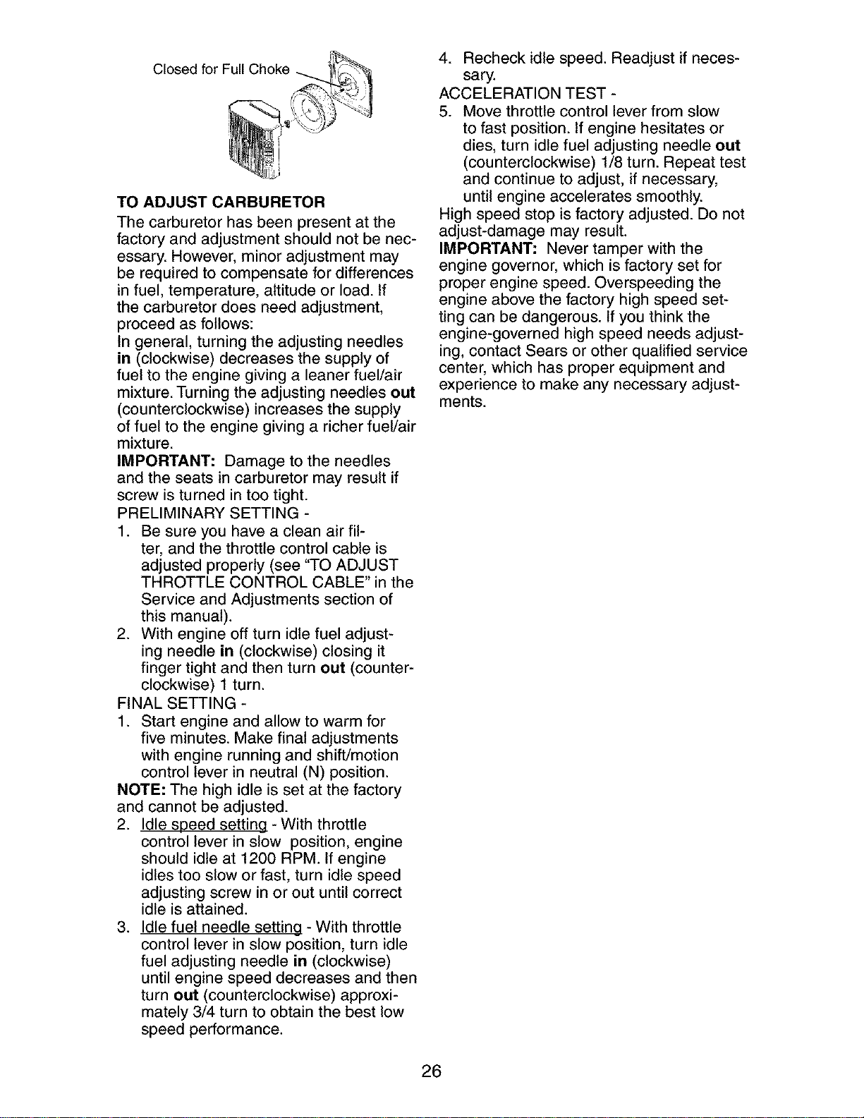
Closed for Full
TO ADJUST CARBURETOR
The carburetor has been present at the
factory and adjustment should not be nec-
essary. However, minor adjustment may
be required to compensate for differences
in fuel, temperature, altitude or load. If
the carburetor does need adjustment,
proceed as follows:
In general, turning the adjusting needles
in (clockwise) decreases the supply of
fuel to the engine giving a leaner fuel/air
mixture. Turning the adjusting needles out
(counterclockwise) increases the supply
of fuel to the engine giving a richer fuel/air
mixture.
IMPORTANT: Damage to the needles
and the seats in carburetor may result if
screw is turned in too tight.
PRELIMINARY SETTING -
1. Be sure you have a clean air fil-
ter, and the throttle control cable is
adjusted properly (see "TO ADJUST
THROTTLE CONTROL CABLE" in the
Service and Adjustments section of
this manual).
2. With engine off turn idle fuel adjust-
ing needle in (clockwise) closing it
finger tight and then turn out (counter-
clockwise) 1 turn.
FINAL SETTING -
1. Start engine and allow to warm for
five minutes. Make final adjustments
with engine running and shift/motion
control lever in neutral (N) position.
NOTE: The high idle is set at the factory
and cannot be adjusted.
2. Idle speed setting - With throttle
control lever in slow position, engine
should idle at 1200 RPM If engine
idles too slow or fast, turn idle speed
adjusting screw in or out until correct
idle is attained.
3. Idle fuel needle setting - With throttle
control lever in slow position, turn idle
fuel adjusting needle in (clockwise)
until engine speed decreases and then
turn out (counterclockwise) approxi-
mately 3/4 turn to obtain the best low
speed performance.
4. Recheck idle speed. Readjust if neces-
sary.
ACCELERATION TEST -
5. Move throttle control lever from slow
to fast position. If engine hesitates or
dies, turn idle fuel adjusting needle out
(counterclockwise) 1/8 turn. Repeat test
and continue to adjust, if necessary,
until engine accelerates smoothly.
High speed stop is factory adjusted. Do not
adjust-damage may result.
IMPORTANT: Never tamper with the
engine governor, which is factory set for
proper engine speed. Overspeeding the
engine above the factory high speed set-
ting can be dangerous. If you think the
engine-governed high speed needs adjust-
ing, contact Sears or other qualified service
center, which has proper equipment and
experience to make any necessary adjust-
ments.
26
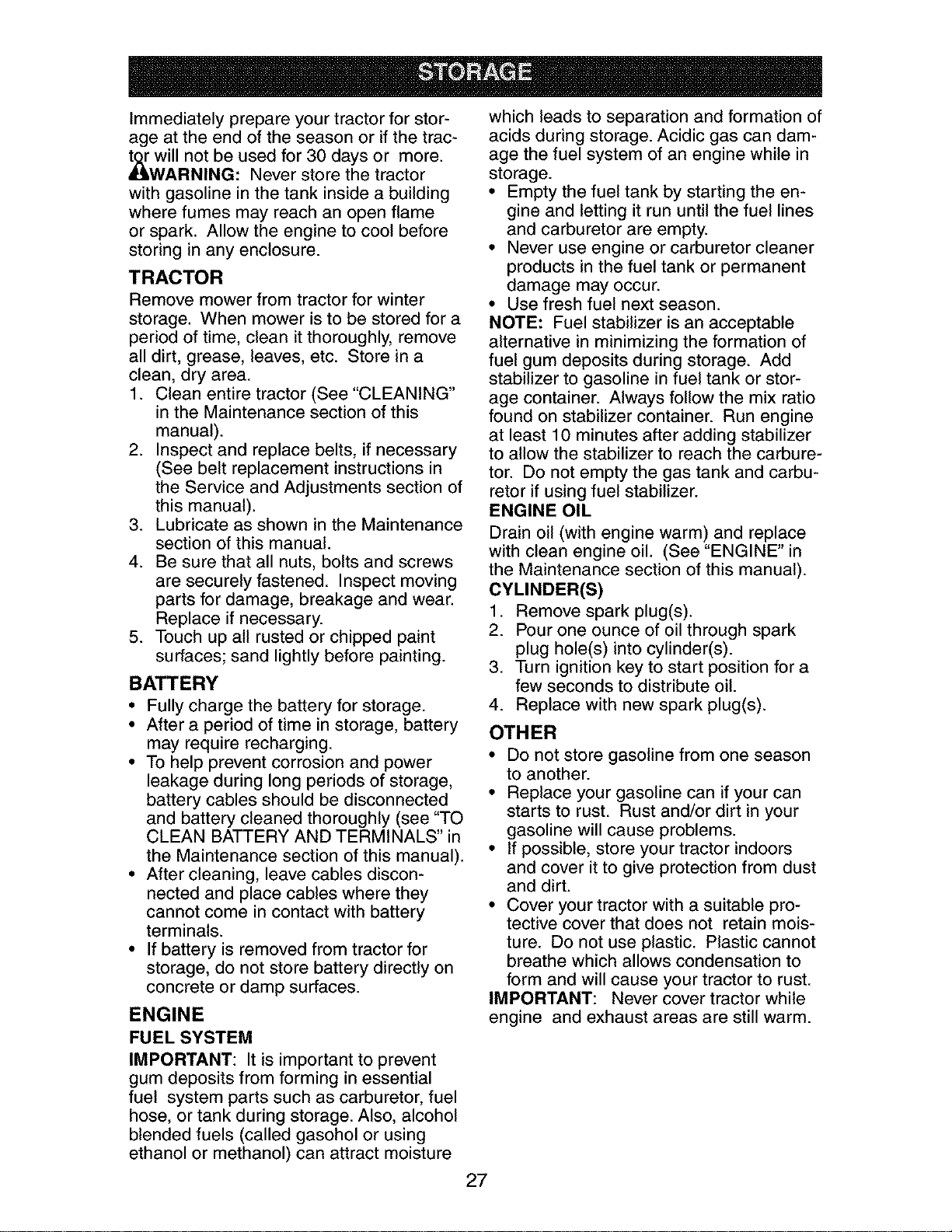
Immediately prepare your tractor for stor-
age at the end of the season or if the trac-
_will not be used for 30 days or more.
WARNING: Never store the tractor
with gasoline in the tank inside a building
where fumes may reach an open flame
or spark. Allow the engine to cool before
storing in any enclosure.
TRACTOR
Remove mower from tractor for winter
storage. When mower is to be stored for a
period of time, clean itthoroughly, remove
all dirt, grease, leaves, etc. Store in a
clean, dry area.
1. Clean entire tractor (See"CLEANING"
in the Maintenance section of this
manual).
2. Inspect and replace belts, ifnecessary
(See belt replacement instructions in
the Service and Adjustments section of
this manual).
3. Lubricate as shown in the Maintenance
section of this manual.
4. Be sure that all nuts, bolts and screws
are securely fastened. Inspect moving
parts for damage, breakage and wear.
Replace if necessary.
5. Touch up all rusted or chipped paint
surfaces; sand lightly before painting.
BATTERY
• Fully charge the battery for storage.
• After a period of time in storage, battery
may require recharging.
• To help prevent corrosion and power
leakage during long periods of storage,
battery cables should be disconnected
and battery cleaned thoroughly (see "TO
CLEAN BATTERY AND TERMINALS" in
the Maintenance section of this manual).
• After cleaning, leave cables discon-
nected and place cables where they
cannot come in contact with battery
terminals.
• If battery is removed from tractor for
storage, do not store battery directly on
concrete or damp surfaces.
ENGINE
FUEL SYSTEM
IMPORTANT: It is important to prevent
gum deposits from forming in essential
fuel system parts such as carburetor, fuel
hose, or tank during storage. Also, alcohol
blended fuels (called gasohol or using
ethanol or methanol) can attract moisture
which leads to separation and formation of
acids during storage. Acidic gas can dam-
age the fuel system of an engine while in
storage.
• Empty the fuel tank by starting the en-
gine and letting it run until the fuel lines
and carburetor are empty.
• Never use engine or carburetor cleaner
products in the fuel tank or permanent
damage may occur.
• Use fresh fuel next season.
NOTE: Fuel stabilizer is an acceptable
alternative in minimizing the formation of
fuel gum deposits during storage. Add
stabilizer to gasoline in fuel tank or stor-
age container. Always follow the mix ratio
found on stabilizer container. Run engine
at least 10 minutes after adding stabilizer
to allow the stabilizer to reach the carbure-
tor. Do not empty the gas tank and carbu-
retor if using fuel stabilizer.
ENGINE OIL
Drain oil (with engine warm) and replace
with clean engine oil. (See "ENGINE" in
the Maintenance section of this manual).
CYLINDER(S)
1. Remove spark plug(s).
2. Pour one ounce of oil through spark
plug hole(s) into cylinder(s).
3. Turn ignition key to start position for a
few seconds to distribute oil.
4. Replace with new spark plug(s).
OTHER
• Do not store gasoline from one season
to another.
• Replace your gasoline can ifyour can
starts to rust. Rust and/or dirt in your
gasoline will cause problems.
• If possible, store your tractor indoors
and cover it to give protection from dust
and dirt.
• Cover your tractor with a suitable pro-
tective cover that does not retain mois-
ture. Do not use plastic. Plastic cannot
breathe which allows condensation to
form and will cause your tractor to rust.
IMPORTANT: Never cover tractor while
engine and exhaust areas are still warm.
27
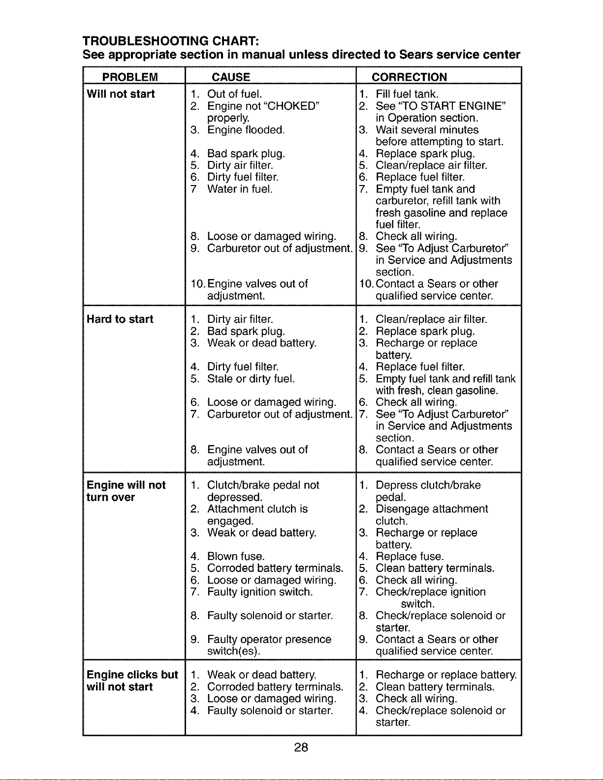
TROUBLESHOOTING CHART:
See appropriate section in manual unless directed to Sears service center
PROBLEM
Will not start
Hard to start
Engine will not
turn over
Engine clicks but
will not start
=
2.
3_
4_
5.
6.
7
8_
9.
10. Engine valves out of
=
2.
3.
4_
5.
6_
7.
8_
2.
3.
4.
5.
6.
7.
8.
9.
=
2.
3.
4.
CAUSE
Out of fuel. 1.
Engine not "CHOKED" 2.
properly.
Engine flooded. 3.
Bad spark plug. 4.
Dirty air filter. 5.
Dirty fuel filter. 6.
Water in fuel. 7.
Loose or damaged wiring. 8.
Carburetor out of adjustment. 9.
adjustment.
Dirty air filter. 1.
Bad spark plug. 2.
Weak or dead battery. 3.
Dirty fuel filter. 4.
Stale or dirty fuel. 5.
Loose or damaged wiring. 6.
Carburetor out of adjustment. 7.
Engine valves out of 8.
adjustment.
Clutch/brake pedal not 1.
depressed.
Attachment clutch is 2.
engaged.
Weak or dead battery. 3.
Blown fuse. 4.
Corroded battery terminals. 5.
Loose or damaged wiring. 6.
Faulty ignition switch. 7.
Faulty solenoid or starter. 8.
Faulty operator presence 9.
switch(es).
Weak or dead battery. 1.
Corroded battery terminals. 2.
Loose or damaged wiring. 3.
Faulty solenoid or starter. 4.
CORRECTION
Fill fuel tank.
See "TO START ENGINE"
in Operation section.
Wait several minutes
before attempting to start.
Replace spark plug.
Clean/replace air filter.
Replace fuel filter.
Empty fuel tank and
carburetor, refill tank with
fresh gasoline and replace
fuel filter.
Check all wiring.
See "To Adjust Carburetor"
in Service and Adjustments
section.
10.Contact a Sears or other
qualified service center.
Clean/replace air filter.
Replace spark plug.
Recharge or replace
battery.
Replace fuel filter.
Empty fuel tank and refill tank
with fresh, clean gasoline.
Check all wiring.
See "To Adjust Carburetor"
in Service and Adjustments
section.
Contact a Sears or other
qualified service center.
Depress clutch/brake
pedal.
Disengage attachment
clutch.
Recharge or replace
battery.
Replace fuse.
Clean battery terminals.
Check all wiring.
Check/replace ignition
switch.
Check/replace solenoid or
starter.
Contact a Sears or other
qualified service center.
Recharge or replace battery.
Clean battery terminals.
Check all wiring.
Check/replace solenoid or
starter.
28
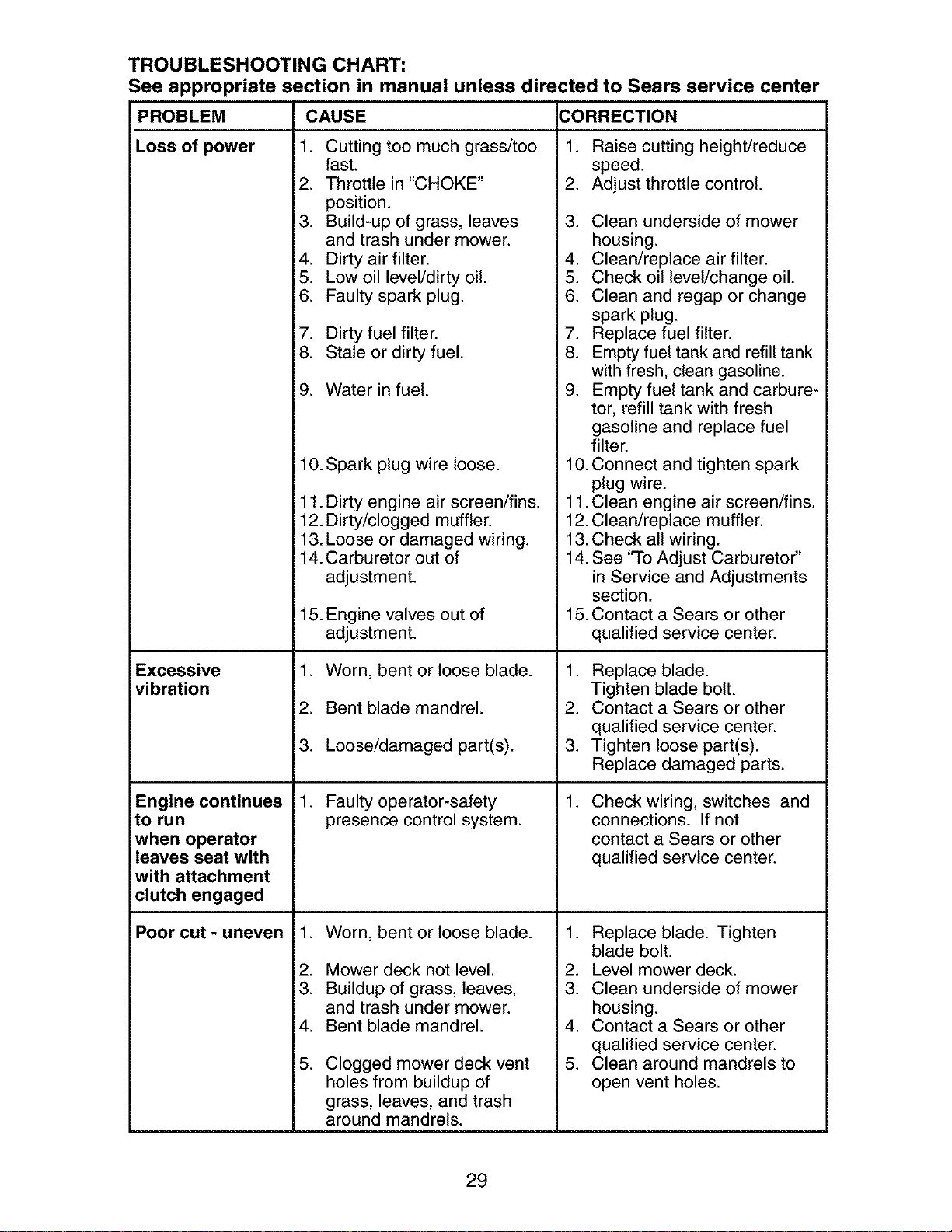
TROUBLESHOOTING CHART:
See appropriate section in manual unless directed to Sears service center
CAUSE CORRECTION
1. Cutting too much grass/too
fast.
2. Throttle in "CHOKE"
position.
3. Build-up of grass, leaves
and trash under mower.
4. Dirty air filter.
5. Low oil level/dirty oil.
6. Faulty spark plug.
7. Dirty fuel filter.
8. Stale or dirty fuel.
i PROBLEM
Loss of power
Excessive
vibration
Engine continues
ito run
when operator
leaves seat with
with attachment
clutch engaged
Poor cut - uneven
9. Water in fuel.
10. Spark plug wire loose.
11. Dirty engine air screen/fins.
12. Dirty/clogged muffler.
13. Loose or damaged wiring.
14. Carburetor out of
adjustment.
15. Engine valves out of
adjustment.
1. Worn, bent or loose blade.
2. Bent blade mandrel.
3. Loose/damaged part(s).
1. Faulty operator-safety
presence control system.
2.
3.
4.
5.
Worn, bent or loose blade.
Mower deck not level.
Buildup of grass, leaves,
and trash under mower.
Bent blade mandrel.
Clogged mower deck vent
holes from buildup of
grass, leaves, and trash
around mandrels.
1. Raise cutting height/reduce
speed.
2. Adjust throttle control.
3. Clean underside of mower
housing.
4. Clean/replace air filter.
5. Check oil level/change oil.
6. Clean and regap or change
spark plug.
7. Replace fuel filter.
8. Empty fuel tank and refill tank
with fresh, clean gasoline.
9. Empty fuel tank and carbure-
tor, refill tank with fresh
gasoline and replace fuel
filter.
10. Connect and tighten spark
plug wire.
11.Clean engine air screen/fins.
12. Clean/replace muffler.
13.Check all wiring.
14. See "To Adjust Carburetor"
in Service and Adjustments
section.
15. Contact a Sears or other
qualified service center.
1. Replace blade.
Tighten blade bolt.
2. Contact a Sears or other
qualified service center.
3. Tighten loose part(s).
Replace damaged parts.
Check wiring, switches and
connections. If not
contact a Sears or other
qualified service center.
1. Replace blade. Tighten
blade bolt.
2. Level mower deck.
3. Clean underside of mower
housing.
4. Contact a Sears or other
qualified service center.
5. Clean around mandrels to
open vent holes.
29
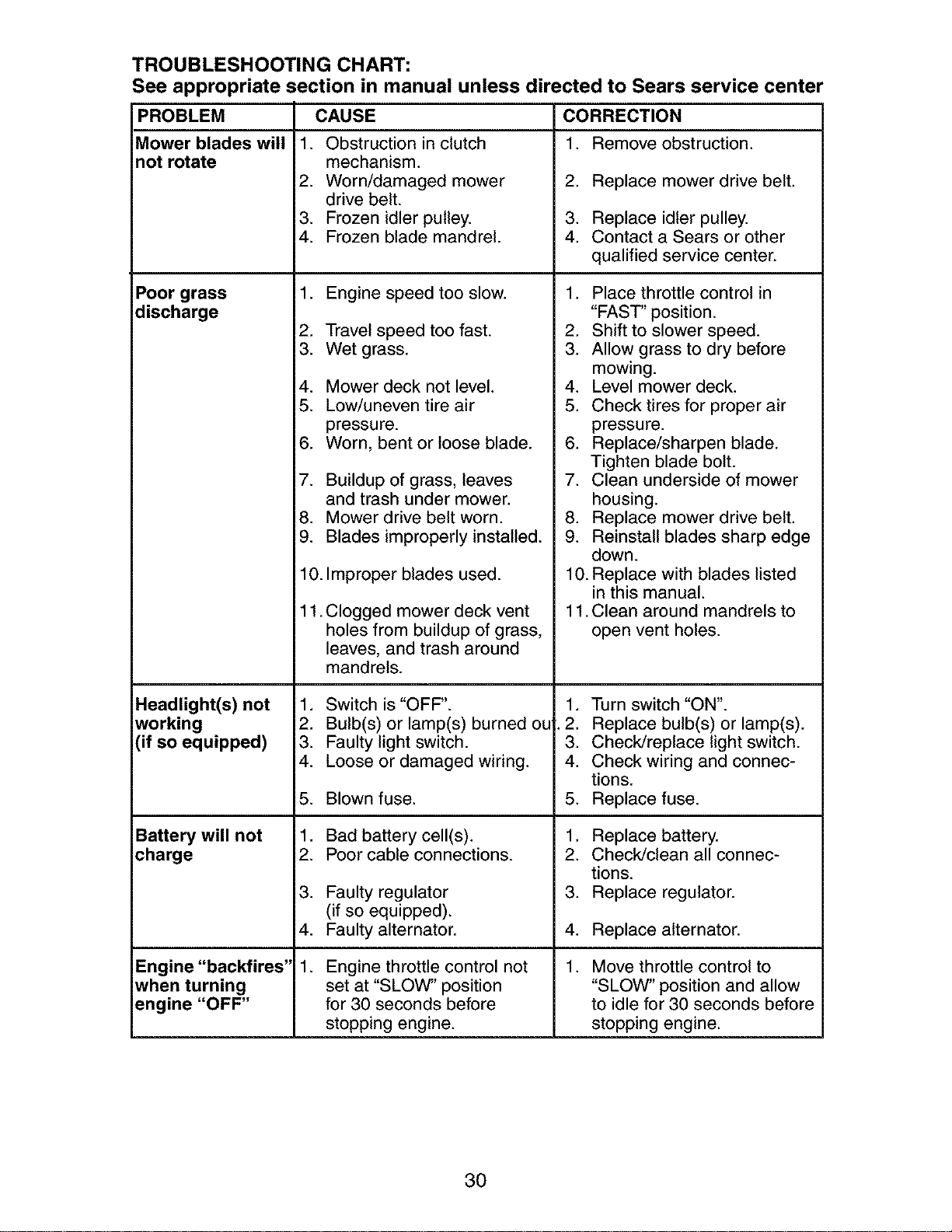
TROUBLESHOOTING CHART:
See appropriate section in manual unless directed to Sears service center
PROBLEM
Mower blades will
not rotate
Poor grass
discharge
CAUSE CORRECTION
1. Remove obstruction.1. Obstruction in clutch
mechanism.
2. Worn/damaged mower
drive belt.
3. Frozen idler pulley.
4. Frozen blade mandrel.
1. Engine speed too slow.
2. Travel speed too fast.
3. Wet grass.
4. Mower deck not level.
5. Low/uneven tire air
pressure.
6. Worn, bent or loose blade.
7. Buildup of grass, leaves
and trash under mower.
8. Mower drive belt worn.
9. Blades improperly installed.
10. Improper blades used.
11. Clogged mower deck vent
holes from buildup of grass,
leaves, and trash around
mandrels.
Headlight(s) not 1.
working 2.
(if so equipped) 3.
4.
5.
Battery will not 1.
charge 2.
3.
4.
1.
Engine "backfires"
when turning
engine "OFF"
Switch is "OFF".
Bulb(s) or lamp(s) burned ou
Faulty light switch.
Loose or damaged wiring.
Blown fuse.
Bad battery cell(s).
Poor cable connections.
Faulty regulator
(if so equipped).
Faulty alternator.
Engine throttle control not
set at "SLOW" position
for 30 seconds before
stopping engine.
2. Replace mower drive belt.
3. Replace idler pulley.
4. Contact a Sears or other
qualified service center.
1. Place throttle control in
"FAST" position.
2. Shift to slower speed.
3. Allow grass to dry before
mowing.
4. Level mower deck.
5. Check tires for proper air
pressure.
6. Replace/sharpen blade.
Tighten blade bolt.
7. Clean underside of mower
housing.
8. Replace mower drive belt.
9. Reinstall blades sharp edge
down.
10. Replace with blades listed
in this manual.
11.Clean around mandrels to
open vent holes.
1. Turn switch "ON".
2. Replace bulb(s) or lamp(s).
3. Check/replace light switch.
4. Check wiring and connec-
tions.
5. Replace fuse.
1. Replace battery.
2. Check/clean all connec-
tions.
3. Replace regulator.
4. Replace alternator.
Move throttle control to
"SLOW" position and allow
to idle for 30 seconds before
stopping engine.
30
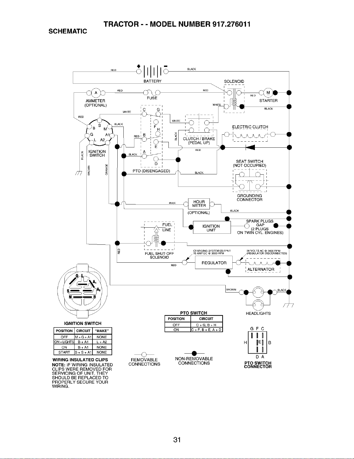
TRACTOR - - MODEL NUMBER 917.276011
SCHEMATIC
BATTERY SOLENOID
D
PTO (DISENGAGED)
ELECTRIC CLUTCH
I i
CLUTCH/BRAKE i j
(PEDAL UP)
SEATSWITCH
(NOT OCCUPIED)
BLACK
GROUNDING
eLUE _ CONNECTOR£LACK
. ; _F SPARKGAPPLUGSi FUEL I IGNITION _ (2 PLUGS
_NE _ UNIT ON TWIN CYL. ENGINES)
I
CHARGING SYSTEM OUTPUT 28 VOLTS AC @ 3600 RPM
FUEL SHUT-OFF _5 AMP PC @ 3600 RPM (REGUt_,TOR DEP_2ONNECT ED!
SOLENOID _AL_EL _NAJT_O_
RE{) REGULATOR I
IGNITION SWITCH
POSITION CtRCUff "MAKE"
OFF M+G+At NONE
3N + UGHT_ B+A1 L+A2
ON B+A1 NONE
START B + S + A1 NONE
WIRING INSULATED CLIPS
NOTE: IF WIRING INSULATED
CLIPS WERE REMOVED FOR
SERVICING OF UNIT, THEY
SHOULD BE REPLACED TO
PROPERLY SECURE YOUR
WIRING.
PrO SWITCH
POSITION CIRCUIT
OFF C+G,B+H
ON C+F,B+E,A+D
© •
REMOVABLE NON-REMOVABLE
CONNECTIONS CONNECTIONS
HEADLIGHTS
GFC
DA
PTO SWITCH
CONNECTOR
31
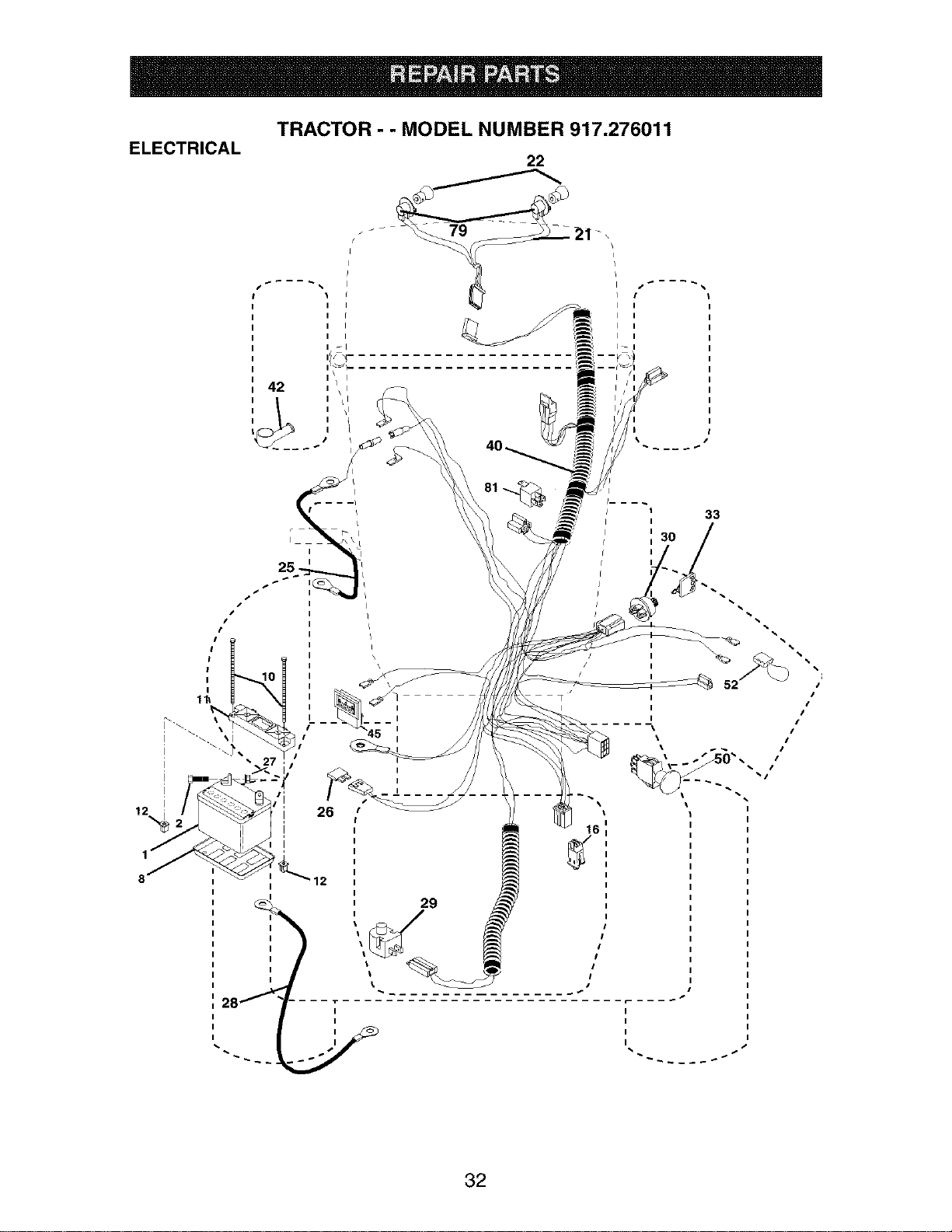
ELECTRICAL
TRACTOR - - MODEL NUMBER 917.276011
I
I
I
I
I
I
I
I
I
, 42
I
I
I
I
I
I
i
i 33
I
29
16
I
I
I
I
32

TRACTOR - - MODEL NUMBER 917.276011
ELECTRICAL
KEY PART
NO. NO. DESCRIPTION
1 144927 Battery
2 74760412 Bolt Hex Head 1/4-20 x 3/4
8 7603J Tray, Battery
10 145211 Bolt 1/4-20 x 7.5 Zinc
11 150109 Hold down Battery Dash Mount
12 145769 Nut Push Nylon 1/4"
16 176138 Switch Interlock Push-In
21 175688 Harness Socket Light W/4152J
22 4152J Bulb Light
25 185456 Cable, Battery.Red .31"
26 108824X Fuse
27 73510400 Nut Keps Hex 1/4-20 Unc
28 170697 Cable, Ground
29 121305X Switch, Plunger
30 175566 Switch, Ign
33 140403 Key, Ignition
40 188032 Harness Ign.
42 154336 Cover, Terminal
45 122822X Ammeter
50 174652 Switch, PTO
52 141940 Protection Wire Loop
79 175242 Bulbholder Asm. Incan descent
81 109748X Relay Asm.
NOTE: All component dimensions given in U.S. inches
1 inch = 25.4 mm
33

TRACTOR - - MODEL NUMBER 917.276011
CHASSIS AND ENCLOSURES
14
138
162
17
21
\
\
\
chassis-stealth 38=vgt
161
158
37
/
28
_86
56
91
85
31
148
_7 17
139 \
j156
130
122
150
122
160
_139
34

TRACTOR - - MODEL NUMBER 917.276011
CHASSIS AND ENCLOSURES
PART
NO. DESCRIPTION
175278
136939
13694O
176018
175476
176016
183569
17000616
19131614
17490608
156973
17490508
177679
144911
74780716
STD551143
180374
17580520
161464
171875
74780716
KEY
NO.
1 180375 Rail, Frame RH
2 175282 Drawbar, Gt
4 73680700 Nut, Crownlock Hex 7/16-14 unc
5 163976X428 Dash YTGT 2 Cyl
6 157882 Dash, Lower Vgt One Piece
7 17720408 Screw, Thd Cut 1/4-20 x 1/2
8 184668 Support, Battery
14 175260X615 Hood Asm
16 121794X Cover, Access
17 17000612 Screw Hex wsh 3/8-16 x 3/4
18 174515X615 Grille
19 19131312 Washer 13/32x13/16x12 Ga.
20 74780616 Bolt Fin Hex 3/8-16 x 1 Gr. 5
21 STD541437 Nut Crownlock 3/8-16 Uric
24 179717X615 Footrest, RH
28 179716X615 Footrest, LH
30 145051X014 Saddle, SIkscr Vgt
31 161419 Bracket Support 1-pc
32 161327 Bracket, Pivot Chassis Lh
33 161326 Bracket, Pivot Chassis Rh
34 177018 Plate Asm Engine Chassis
35 19111116 Washer 11/32x11/16x16 Ga.
36 17060512 Screw 5/16-18 x 3/4
37 179772X615 Fender
39 Bracket, Axle Front
43 Bracket, Spnsn Front Lh
44 Bracket, Spnsn Front Rh
45 Bracket Chassis
50 Bracket, Chassis Front
56 Bracket Asm., Susp Chassis Lh
58 Bracket Fender
60 ScrewThdroL 3/8-16 x 1
63 Washer 13/32 x 1 x 14 Ga.
66 Screw 3/8-16 x 1/2
67 Guide, Belt Gear Drive
68 ScrewThdroL 5/16-18 x 1/2
70 Belt Keeper VGT Ground Drive
85 Bracket, Support Transaxle
86 Bolt Fin Hex 7/16-14 UNC x 1
88 Washer, Lock Hvy HIcl Spr 7/16
91 Rail, Frame Lh
106 Screw Thdrol 5/16-18 x 1.25
122 Screw Hex Wshd 8-18 x 7/8
130 Screw HWHD HFLo #13-16 x 3/4
137 Bolt Fin Hex 7/16-14 xl Gr. 5
138 179125X428 CupholderYTGT
139 171873 Bolt Shoulder 5/16-18 TT
142 161897 Bracket Dash Rh
144 161900 Bracket Dash Lh
148 164655 Extrusion Bumper
150 175352 Duct Heat Hood
152 177956 Shield Browning
153 179761 Light Box Asm w/Lens
156 17000512 Screw 5/16-18 x 3/4. BIk
157 161840 Lens Bar
158 17670608 ScrewThdroL 3/8-16 x 1/2
160 17000512 Screw 5/16-18 x 3/4
161 179612X428 Console FueIWindow
162 142432 Screw HexWsh Hi-Lo 1/4-1/2
165 183554 Bracket Support Tank
NOTE: All component dimensions given in U.S.
inches 1 inch = 25.4 mm
35
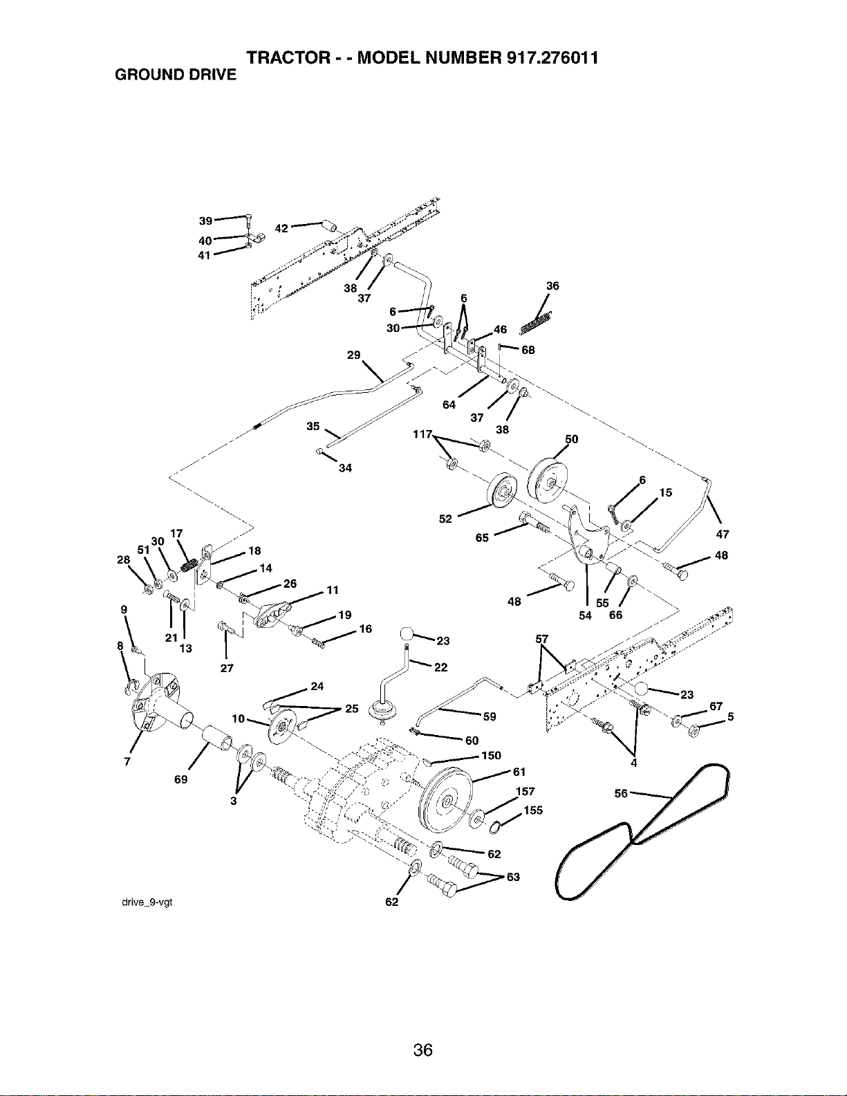
TRACTOR - - MODEL NUMBER 917.276011
GROUND DRIVE
42"----"_
28
\
13
27
69
3
i 38 36
=', 37 6 /
52
65
57
157
155
15
47
drive 9-vg
62
36

TRACTOR - - MODEL NUMBER 917.276011
GROUND DRIVE
KEY PART
NO. NO. DESCRIPTION
3 7563R Washer, Thrust, Axle
4 17490508 Screw Thdrol 5/16-18 x 3/4
5 STD541437 Nut, Crownlock 3/8-16
6 STD561210 Pin, Cotter
7 149176 Wheel, Hub Assembly
8 12000034 Klip, Ring
9 140080 Bolt, Hub
10 142509 Disc, Brake
11 136927 Yoke, Brake Disc
12 73750800 Nutlock 1/2-20 Unf
13 139419 Washer, Special
14 138901 Bushing
15 STD551037 Washer 13/32x13/16 x 16 Ga.
16 143012 Set, Screw 1/4-28 x 3/4
17 126909X Spring
18 137104 Lever, Brake
19 136926 Cam, Brake Disc
21 23260412 Screw, Flat Head 1/4-28 x 3/4
22 633A109 Gearshift, Lever Assembly
23 106932X Knob
24 136925 Support, Puck Brake
25 136923 Puck, Brake Top
26 137552 Spring, Return
27 17490528 Screw, Hex Wsh Thd. 5/16-18 x 1-3/4
28 73350600 Nut, Hex Jam 3/8-16
29 137213 Brake, Rod
30 19131616 Washer 13/32 x 1 x 16 Ga.
34 71673 Cap, Plunger
35 137648 Rod, Parking Brake
36 149412 Spring, Drive Ground
37 121749X Washer 25/32 x1-1/4 x 16 Ga.
38 150035 Nyliner
39 74321016 Screw, Fin. #10-24 x 1
40 178575 Actuator, Interlock Switch
41 73931000 Nut, Centerlock #10-24
42 8883R Cover, Pedal
46 145170 Retainer, Spring
47 138228 Clutch Rod
48 72110612 Bolt, Carr. 3/8-16 x 1-1/2 Gr. 5
50 131494 Pulley, Idler, Flat
51 STD541437 Nut, Crownlock 3/8-16 UNC
52 139123 Pulley, Idler, Grooved
54 161590 Clutch, Arm Assembly
55 105706X Bearing, Idler
56 137153 V-Belt
57 141756 Bracket, Shift Rod, Hi-Lo
59 122253X Shift Rod, Hi-Lo
60 122268X Spring Clip, Connecting Link
61 184987 Pulley, Transaxle
62 STD551143 Washer, Lock 7/16
63 74780720 Bolt, Fin Hex 7/16-14 x 1-1/4
64 154752 Shaft, Clutch/Brake Pedal
65 179613 Bolt, Shoulder
66 140296 Washer, Hardened
67 19131312 Washer, Flat
68 5142H Pin, Roll
69 136327 Hub, Cover
117 73900600 Nut, Lock Fig. 3/8-16 Uric
150 9858M1 Key, Woodruff
155 12000028 Ring Retainer
157 1370H Washer Thrust 5/8 x 1.10 x 1/32
NOTE: All component dimensions given in U.S.
inches 1 inch = 25.4 mm
37

TRACTOR - - MODEL NUMBER 917.276011
STEERING ASSEMBLY
51
fill Ix _ J I
14
20
23
34
33
42
13
28
\
\,
15 _),/ +" _\
/ \1
13 / I
I I I
\ I
8
/
/
\,
\
\
J
/
35
18_._/_ steering 16wgt
J
J
38
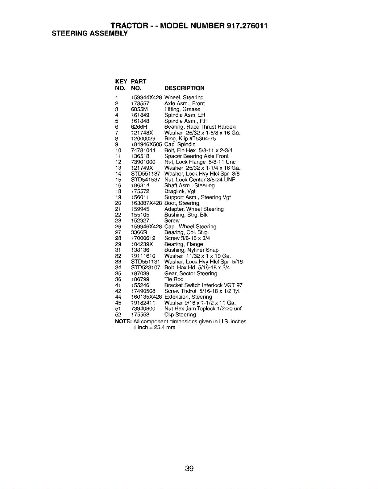
TRACTOR - - MODEL NUMBER 917.276011
STEERINGASSEMBLY
KEY PART
NO. NO. DESCRIPTION
1 159944X428
2 178557
3 6855M
4 161849
5 161848
6 6266H
7 121748X
8 12000029
9 184946X505
10 74781044
11 136518
12 73901000
13 121749X
14 STD551137
15 STD541537
16 186814
18 175572
19 156011
20 163887X428
21 159945
22 155105
23 152927
26 159946X428
27 3366R
28 17000612
29 104239X
31 138136
32 19111610
33 STD551131
34 STD523107
35 187039
36 186799
41 155246
42 17490508
44 160135X428
45 19182411
51 73940800
52 175553
Wheel, Steering
Axle Asm., Front
Fitting, Grease
Spindle Asm, LH
Spindle Asm., RH
Bearing, Race Thrust Harden
Washer 25/32 x 1-5/8 x 16 Ga.
Ring, Klip #T5304-75
Cap, Spindle
Bolt, Fin Hex 5/8-11 x 2-3/4
Spacer Bearing Axle Front
Nut, Lock Flange 5/8-11 Uric
Washer 25/32 x 1-1/4 x 16 Ga.
Washer, Lock Hvy Hlcl Spr 3/8
Nut, Lock Center 3/8-24 UNF
Shaft Asm., Steering
Draglink, Vgt
Support Asm, Steering Vgt
Boot, Steering
Adapter, Wheel Steering
Bushing, Strg. BIk
Screw
Cap, Wheel Steering
Bearing, Col. Strg.
Screw 3/8-16 x 3/4
Bearing, Flange
Bushing, Nyliner Snap
Washer 11/32 x 1 x 10 Ga.
Washer, Lock Hvy HIcl Spr 5/16
Bolt, Hex Hd 5/16-18 x 3/4
Gear, Sector Steering
Tie Red
Bracket Switch Interlock VGT 97
ScrewThdrol 5/16-18 x 1/2Tyt
Extension, Steering
Washer 9/16 x 1-1/2 x 11 Ga.
Nut Hex Jam Toplock 1/2-20 unf
Clip Steering
NOTE: All component dimensions given in U.S. inches
1 inch = 25.4 mm
39
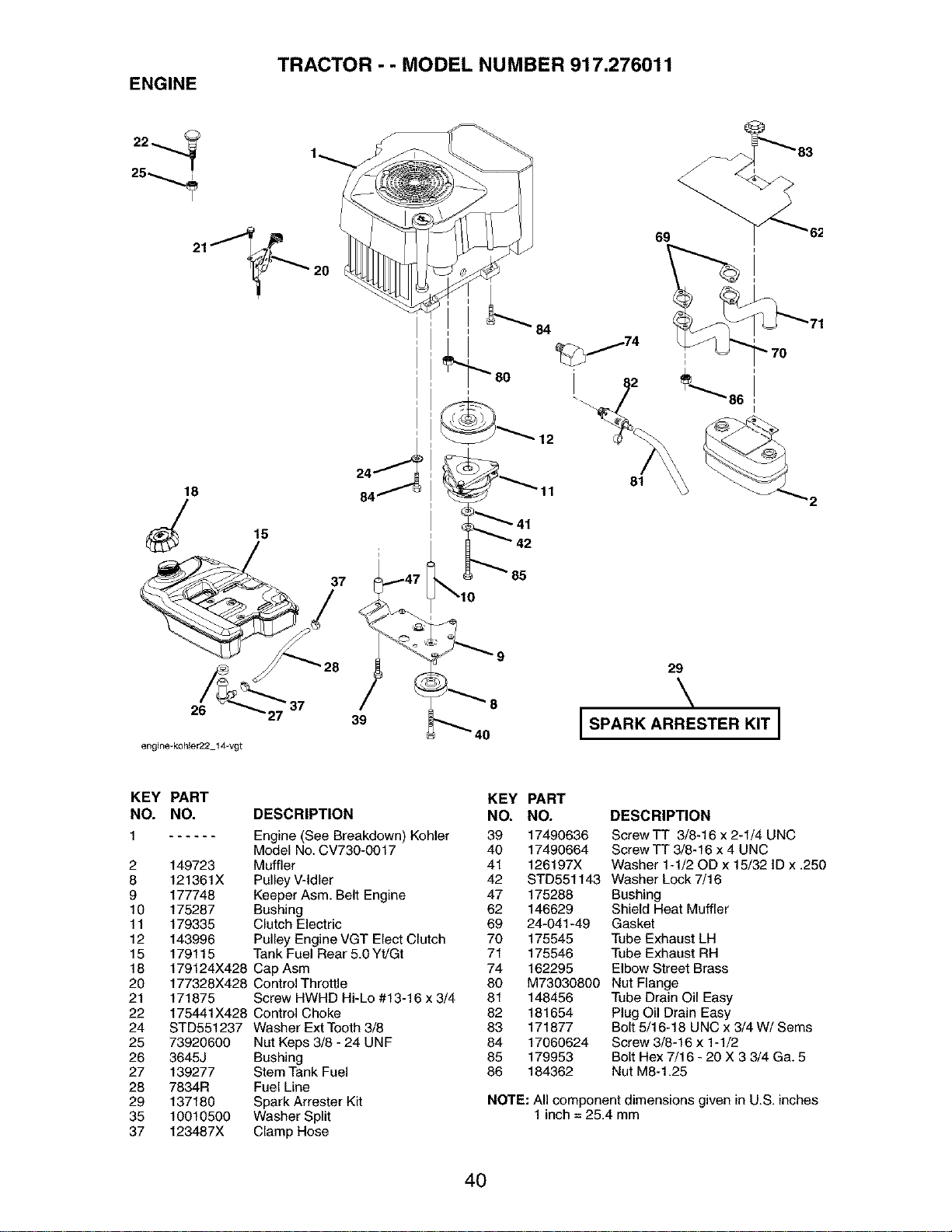
TRACTOR - - MODEL NUMBER 917.276011
ENGINE
18
26
engine-k0hler22 14-vgt
15
/
39
84
12
85
69
81
29
\
I SPARK ARRESTER KIT I
KEY PART
NO. NO. DESCRIPTION
1 Engine (See Breakdown) Kohler
Model No.CV730-0017
2 149723 Muffler
8 121361X Pulley V-tdler
9 177748 Keeper Asm. Belt Engine
10 175287 Bushing
11 179335 Clutch Electric
12 143996 Pulley Engine VGT Elect Clutch
15 179115 Tank Fuel Rear 5.0 Yt/Gt
18 179124X428 Cap Asm
20 177328X428 Control Throttle
21 171875 Screw HWHD Hi-Lo #13-16 x 3/4
22 175441X428 Control Choke
24 STD551237 Washer Ext Tooth 3/8
25 73920600 Nut Keps 3/8 - 24 UNF
26 3645J Bushing
27 139277 Stem Tank Fuel
28 7834R Fuel Line
29 137180 Spark Arrester Kit
35 10010500 Washer Split
37 123487X Clamp Hose
KEY PART
NO. NO. DESCRIPTION
39 17490636 Screw TT 3/8-16 x 2-1/4 UNC
40 17490664 Screw TT 3/8-16 x 4 UNC
41 126197X Washer 1-1/20D x 15/32 ID x .250
42 STD551143 Washer Lock 7/16
47 175288 Bushing
62 146629 Shield Heat Muffler
69 24-041-49 Gasket
70 175545 Tube Exhaust LH
71 175546 Tube Exhaust RH
74 162295 Elbow Street Brass
80 M73030800 Nut Flange
81 148456 Tube Drain Oil Easy
82 181654 Plug Oil Drain Easy
83 171877 Bolt 5/16-18 UNC x 3/4 W/Sems
84 17060624 Screw 3/8-16 x 1-1/2
85 179953 Bolt Hex 7/16 - 20 X 3 3/4 Ga. 5
86 184362 Nut M8-1.25
NOTE: All component dimensions given in U.S. inches
1 inch = 25.4 mm
40
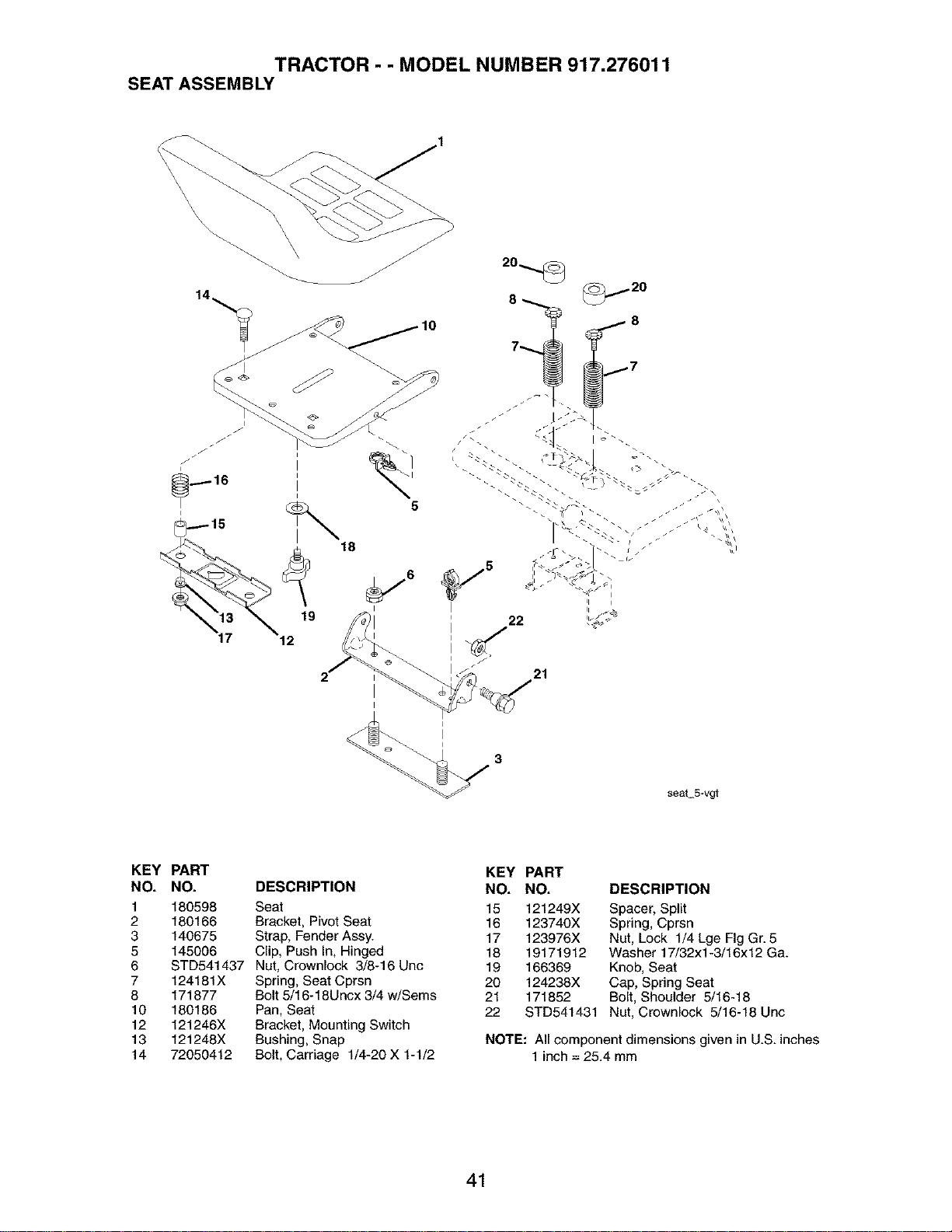
TRACTOR - - MODEL NUMBER 917.276011
SEAT ASSEMBLY
\
\
/I
5
I
18
19
12
_6
seat S-vgt
KEY PART
NO. NO. DESCRIPTION
1 180598 Seat
2 180166 Bracket, Pivot Seat
3 140675 Strap, Fender Assy.
5 145006 Clip, Push In, Hinged
6 STD541437 Nut, Crewnieck 3/8-16 Unc
7 124181X Spring, Seat Cprsn
8 171877 Bolt 5/16-18Uncx 3/4 w/Sems
10 180186 Pan, Seat
12 121246X Bracket, Mounting Switch
13 121248X Bushing, Snap
14 72050412 Bolt, Carriage 1/4-20 X 1-1/2
KEY PART
NO. NO. DESCRIPTION
15 121249X Spacer, Split
16 123740X Spring, Cprsn
17 123976X Nut, Lock 1/4 Lge Fig Gr. 8
18 19171912 Washer 17/32x1-3/16x12 Ga.
19 166369 Knob, Seat
20 124238X Cap, Spring Seat
21 171852 Bolt, Shoulder 5/16-18
22 STD541431 Nut, Crownleck 5/16-18 Unc
NOTE: All component dimensions given in U.S. inches
1 inch = 25.4 mm
41
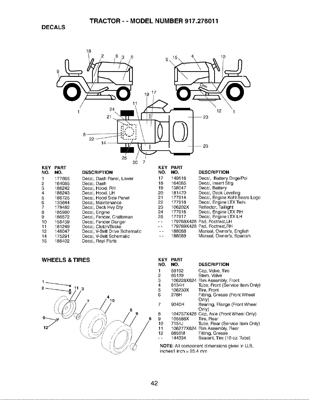
TRACTOR - - MODEL NUMBER 917.276011
DECALS
I8
2 6
5_
4
I0
I9 I7
/
1
24
12
6_
KEY PART
NO, NO.
1 177665
2 164685
3 186242
4 186243
5 I86725
6 133644
7 178482
8 185980
9 I86572
10 156439
11 181249
12 I46647
14 175291
15 186402
25
20
DESCRIPTION
Decal Dash Panel, Lower
Decal Dash
Decal Hood, RH
Decal Hood, LH
Decal HOod Side Panel
Decal Maintenance
Decal Deck Hvy Dry
Decal Engine
Decal Fender, Craftsman
Decal Fender Danger
Decal Clute_Brake
Decal V-Belt Drive Schematic
Decal V-Belt Schematic
Decal Repl Parts
KEY PART
NO, NO. DESCRIPTION
17 149516 Decal, Battery Dnge/Poi
18 164065 Decal, Insert Strg
19 I38047 Decal, Battery
20 181470 Decal, Deck Leveling
21 I77914 Decal, Engine Kohl Sears Logo
22 177918 Decal, Engine LTXTwin
23 I06202X Reflector, Taillight
24 177916 Decal, Engine LTX RH
25 177917 Decal, Engine LTX LH
- - I79768X428 Pad, Footrest,LH
- - 179769X426 Pad, Footres%RH
- - 188068 Manual, Owner's, English
- - 188069 Manual, Owner's, Spanish
WHEELS & TIRES
3
7
4
10
KEY PART
NO, NO. DESCRIPTION
1
2
3
4
5
6
7
8
9
10
11
12
59192 Cap, Valve, Tire
65139 Stem, Valve
I06228X624 Rim Assembly, Front
6134H Tube, Front (Service item Only)
I06230X Tire, Front
278H Fitting, Grease (Front Wheel
Only)
9O4OH Bearing, Flange (Front Wheel
Only)
I04757X426 Cap, Axle (Front Wheel Only)
I05588X Tire, Rear
7154J Tube, Rear (Service Item Only)
I06277X624 Rim Assembly. Rear
6856M Fitting, Grease
I44334 Sealant, Tire (I0 oz. Tube)
NOTE: All _mponent dimensions given in U.S.
inches1 inch = 25.4 mm
42
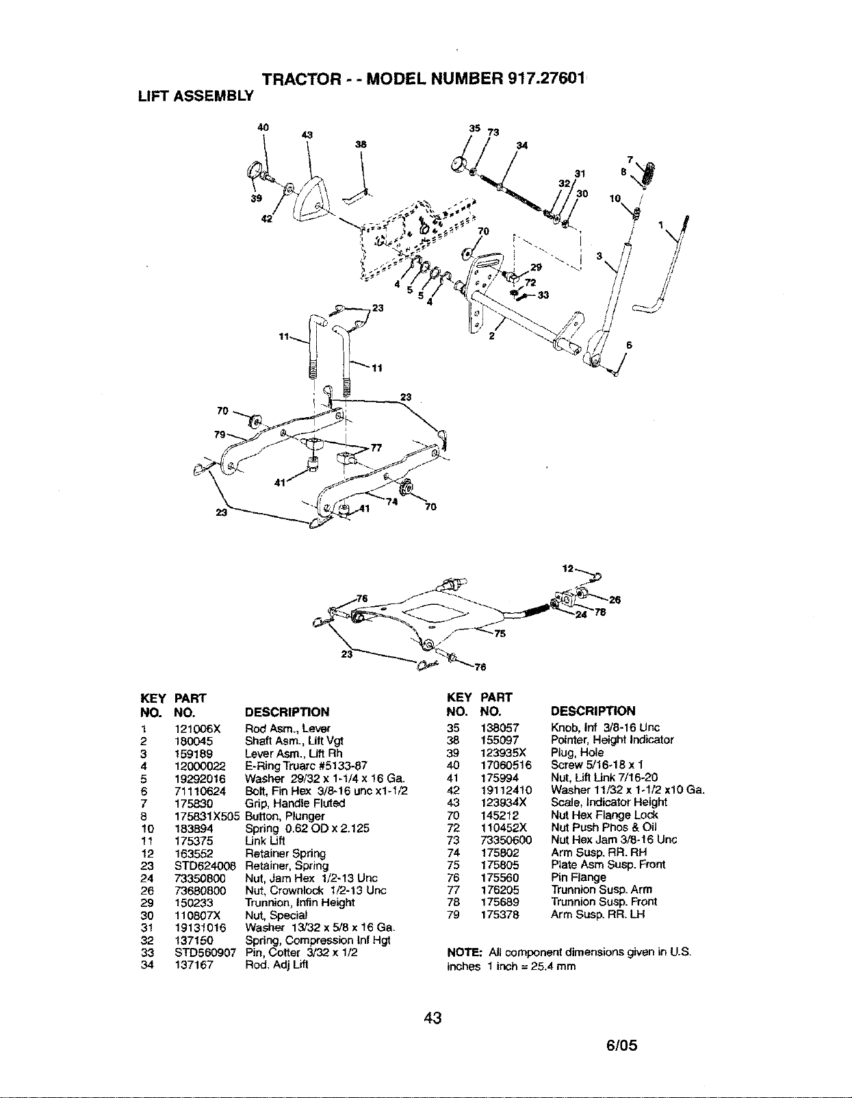
TRACTOR - - MODEL NUMBER 917.27601
LIFT ASSEMBLY
7O
4O
38
39
42
7O
KEY PART
NO. NO.
1 12t006X
2 180045
3 159189
4 12000022
5 19292016
6 71110624
7 175830
8 175831X505
10 183894
11 175375
12 163552
23 STD624008
24 73350800
26 73680800
29 150233
30 110807)(
31 19131016
32 137150
33 STD560907
34 137167
76 j F'_ 12_ 26
KEY PART
DESCRIPTION NO. NO. DESCRIPTION
Rod Asm., Lever 35 138057 Knob,|nf 3/6-16 Unc
Shaft Asm., LiftVgt 38 155097 Pointer,Height Indicator
Lever Asrn.>Utt Rh 39 123935X Plug, Hole
E-Ring Truarc #5133-87 40 17060516 Screw 5/16o18 x 1
Washer 29/32 x 1-1/4 x 16 Ga. 41 175994 Nut, Lift Link 7/16-20
Bolt, Fin Hex 3/8-16 une x1-1/2 42 191124t0 Washer 11/32 x 1-1/2 xl0 Ga,
Grip, Handle Fluted 43 123934X Scale, Indicator Height
Button, Plunger 70 145212 Nut Hex Flange Lock
Spring 0.62 OD x 2.125 72 110452X Nut Push Phos & Oil
LinkLift 73 73350600 NutHex Jam 3/8-16 Unc
Retainer Spring 74 175802 Arm Susp. RR. RH
Retainer, Spring 75 175805 Plate Asm Susp. Front
Nut, Jam Hex 1/2-13 Unc 76 175560 Pin Flange
Nut, Crownlock 1/2-13 Unc 77 176205 Trunnion Susp. Arm
Trunnion, tnfin Height 78 175689 Trunnion Susp. Front
Nut, Special 79 175378 Arm Susp. RR. LH
Washer 13/32 x 5/8 x 16 Ga.
Spring, Compression Inf Hgt
Pin, Cotter 3/32 x 1/2 NOTE: All component dimensionsgiven inU.S.
Rod. Adj Lift inches 1 inch = 25.4 mm
43
6/05
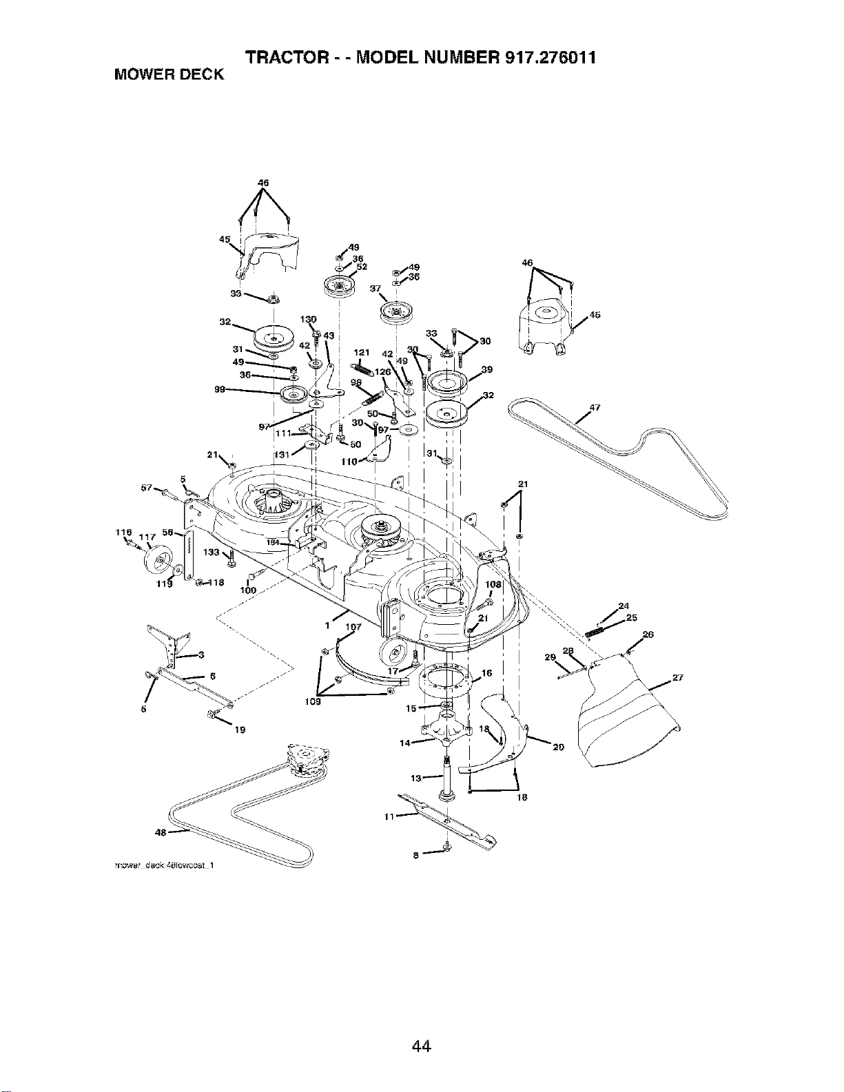
TRACTOR - - MODEL NUMBER 917.276011
MOWER DECK
46
5
47
19
24
44
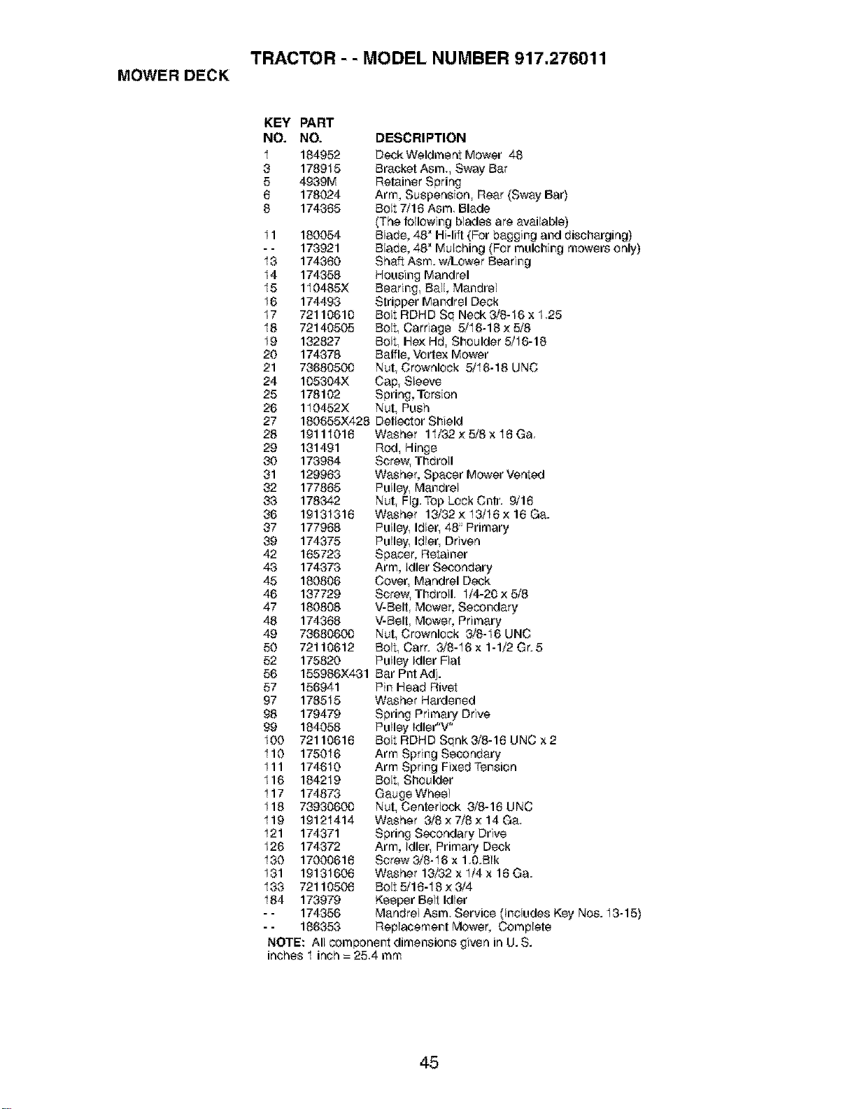
TRACTOR - - MODEL NUMBER 917.276011
MOWER DECK
KEY PART
NO. NO.
I 184952
3 178915
5 4939M
6 178024
8 174365
I1 180054
-- 173921
I3 174360
I4 174358
I5 110485X
I6 174493
I7 72116616
I8 72140505
I9 132827
20 174378
21 73686506
24 165364X
25 178102
26 110452X
27 180655)(428
28 19111016
29 131491
30 173984
31 129963
32 177865
33 178342
36 19131316
37 177968
39 174375
42 165723
43 174373
45 180866
46 137729
47 180808
48 174368
49 73686606
50 72110612
52 175820
56 155986)(431
57 156941
97 178515
98 179479
99 184058
I00 72116616
I10 175016
Ill 174610
I16 184219
I17 174873
I18 73936606
I19 19121414
I21 174371
I26 174372
I30 17000616
I31 19131606
I33 72110506
I84 173979
-- 174356
-- 186353
DESCRIPTION
DeckWeldment Mower 48
Bracket Asm. Sway Bar
Retainer Spring
Arm, Suspension, Rear (Sway Bar)
Bolt 7/16 Asm. Blade
(The following blades are available)
Blade, 48" Hi-lift (For bagging and discharging)
Blade, 48" Mulching (For mulching mowers only)
Shaft Asm. w/Lower Bearing
Housing Mandrel
Bearing Ball, Mandrel
Stripper Mandrel Deck
Bolt RDHD Sq Neck 3/8-I6 x 1.25
Bolt, Carriage 5/I6-18 × 5/8
Bolt, He;<Hd, Shoulder 5/I6-18
Baffle, Vortex Mower
Nut, Crownlock 5/I6-18 UNC
Cap, Sleeve
Spring, Torsion
Nut Push
Deflector Shield
Washer 11/32 × 5/8 x 16 Ga.
Rod Hinge
Screw, Thdroll
Washer, Spacer Mower Vented
Pulley, Mandrel
Nut Fig.Top Lock Cntr. 9/16
Washer 13/32× I3/I6× 16 Ga.
Pulley, Idler, 48 Primary
Pulley, Idler, Driven
Spacer, Retainer
Arm, Idler Secondary
Cover, Mandrel Deck
Screw, Thdroll. I/4-20 × 5/8
V-Belt, Mower, Secondary
V-Belt Mower, Primary
Nut, Crownlock 3/8-I6 UNC
Bolt, Carr. 3/8-I6 x 1-1/2 Gr. 5
Pulley idler Flat
Bar Pnt Adi.
Pin Head Rivet
Washer Hardened
Spring Primary Drive
Pulley Idler"V"
Bolt RDHD Sqnk 3/8-16 UNC x 2
Arm Spring Secondary
Arm Spring Fixed Tension
Bolt Shoulder
Gauge Wheel
Nut Centerleck 3/8-16 UNC
Washer 3/8 × 7/8 × 14 Ga.
Spring Secondary Drive
Arm, Idler, Primary Deck
Screw 3/8-I6 x 1.O.BIk
Washer 13/32 x I/4 x 16 Ga.
Bolt 5/16-I 8 × 3/4
Keeper Belt Idler
Mandrel Asm. Service (Includes Key Nos. I3-15)
Replacement Mower, Complete
NOTE: All component dimensions givenin U.S.
inches I inch = 25.4mm
45
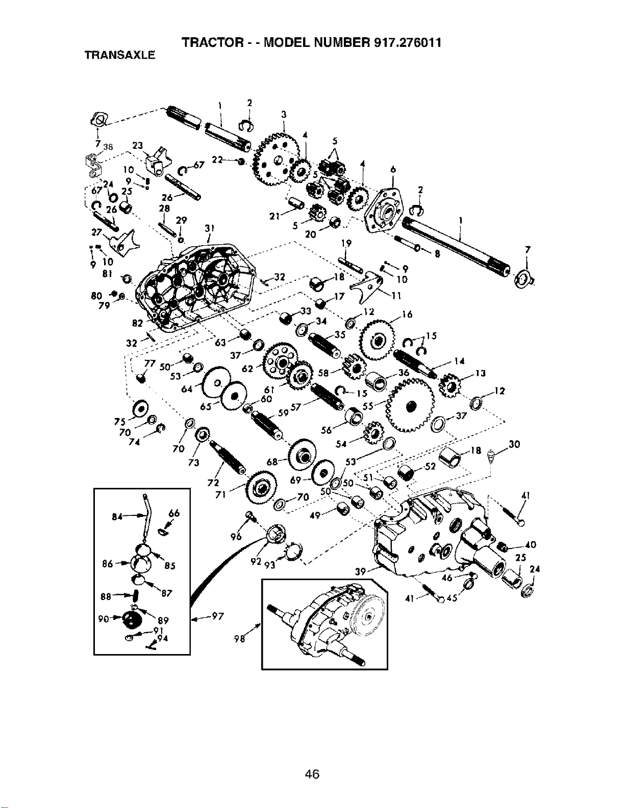
TRACTOR - - MODEL NUMBER 917.276011
TRANSAXLE
3
2O
5
4
6
2
1
8O
74
70
73
72
62
61
.595_
7
41
25
24
46
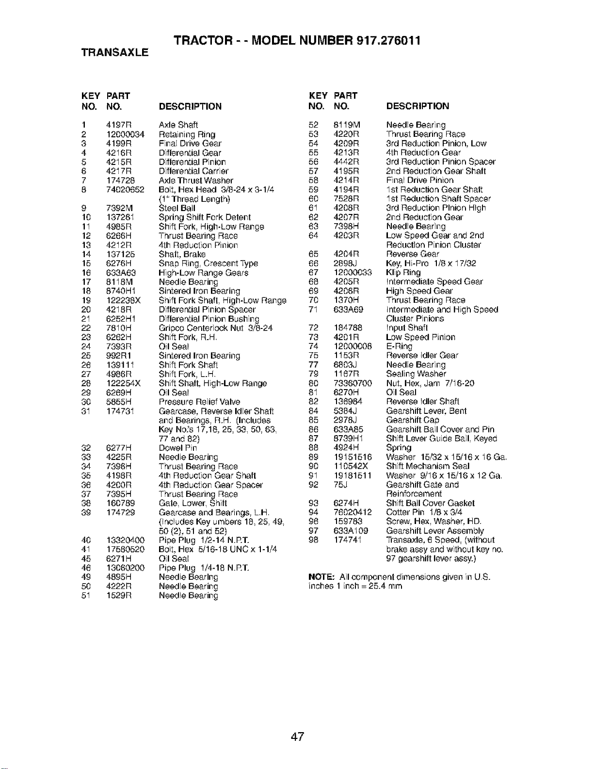
TRACTOR - - MODEL NUMBER 917.276011
TRANSAXLE
KEY PART
NO. NO.
1 4197R
2 12000034
3 4199R
4 4216R
5 4215R
6 4217R
7 174726
8 74020652
9 7392M
10 13726I
11 4965R
12 6266H
13 4212R
14 137125
15 6276H
16 633A68
17 8118M
16 8740HI
19 122236X
20 4218R
21 6252HI
22 781 OH
23 6262H
24 7393R
25 992R1
26 139111
27 4966R
26 122254X
29 6269H
30 5855H
3I 174731
32 6277H
3,3 4225R
34 7396H
35 4198R
36 4200R
37 7395H
38 160789
39 174729
40 13320400
4I 17580520
45 6271H
46 13060200
49 4895H
50 4222R
5I 1529R
KEY PART
DESCRIPTION NO. NO. DESCRIPTION
Axle Shaft 52 8119M
Retaining Ring 53 4220R
Final Drive Gear 54 4209R
Differential Gear 55 4213R
Differential Pinion 56 4442R
Differential Carrier 57 4I 95R
A;<leThrust Washer 58 4214R
Boll, Hex Head 3/6-24 ;<3-1/4 59 4I 94R
(4" Thread Length) 60 7528R
Steel Ball 6I 4208R
Spring Shill Fork Detent 62 4207R
Shift Fork, High-Low Range 68 7398H
Thrust Bearing Race 64 4203R
4th Reduction Pinion
Shaft, Brake 65 4204R
Snap Ring Crescent Type 66 2898J
High-Low Range Gears 67 12000033
Needle Bearing 68 4205R
Sintered Iron Bearing 69 4206R
Shift Fork Shaft, High-Low Range 70 1370H
Differential Pinion Spacer 7I 683A69
Differential Pinion Bushing
Grip_ Centedock Nut 3/6-24 72 164786
Shift Fork, R.H. 73 4201R
Oil Seal 74 12000008
Sintered Iron Bearing 75 1153R
Shift Fork Shaft 77 6803J
Shift Fork, L.H. 79 1I 67R
Shift Shaft, High-Low Range 60 73360700
Oil Seal 64 6270H
Pressure Relief Valve 62 136984
Gearcase, Reverse Idler Shaft 64 5364J
and Bearings, R.H (Includes 65 2978J
Key No.%17,16, 25, 33, 50, 63, 66 633A85
77 and 62) 67 8739HI
Dowel Pin 88 4924H
Needle Bearing 69 19151516
Thrust Bearing Race 90 110542X
4th Reduction Gear Shaft 9I 19181511
4th Reduction Gear Spacer 92 75J
Thrust Bearing Race
Gate, Lower, Shift 93 6274H
Gearcase and Bearings, L.H 94 76020412
(Includes I_y umbers 16, 25, 49, 96 159783
50 (2), 51 and 52) 97 633AI09
Pipe Plug 4/2-14 N.RT. 96 174744
Bolt, Hex 5/16-I8 UNC;< 1-1/4
Oil Seal
Pipe Plug 4/4-16 N.RT.
Needle Bearing
Needle Bearing
Needle Bearing
Needle Bearing
Thrust Bearing Race
3rd Reduction Pinion, Low
4th Reduction Gear
3rd Reduction Pinion Spacer
2nd Reduction Gear Shaft
Final Drive Pinion
1st Reduction Gear Shall
1st Reduction Shaft Spacer
3rd Reduction Pinion High
2nd Reduction Gear
Needle Bearing
Low Speed Gear and 2nd
Reduction Pinion Cluster
Reverse Gear
Key, Hi-Pro 1/6 ;<I7/32
Klip Ring
intermediate Speed Gear
High Speed Gear
Thrust Bearing Race
intermediate and High Speed
Cluster Pinions
Input Shaft
Low Speed Pinion
E-Ring
Reverse Idler Gear
Needle Bearing
Sealing Washer
Nut, He;<, Jam 7/I6-20
Oil Seal
Reverse Idler Shaft
Gearshift Lever, Bent
Gearshift Cap
Gearshift Ball Cover and Pin
Shift Lever Guide Ball, Keyed
Spring
Washer 15/32 x 15/16 ;<I6 Ga.
Shift Mechanism Seal
Washer 9/I6 ;<15/16 x I2 Ga.
Gearshift Gate and
Reinforcement
Shift Ball Cover Gasket
Cotter Pin I/8 x 3/4
Screw, Hex, Washer, HD.
Gearshift Lever Assembly
Transa;<le, 6 Speed, (without
brake assy and without key no.
97 gearshift lever assy.)
NOTE: All _mponent dimensions given in U.S.
inches 1 inch = 25.4 mm
47
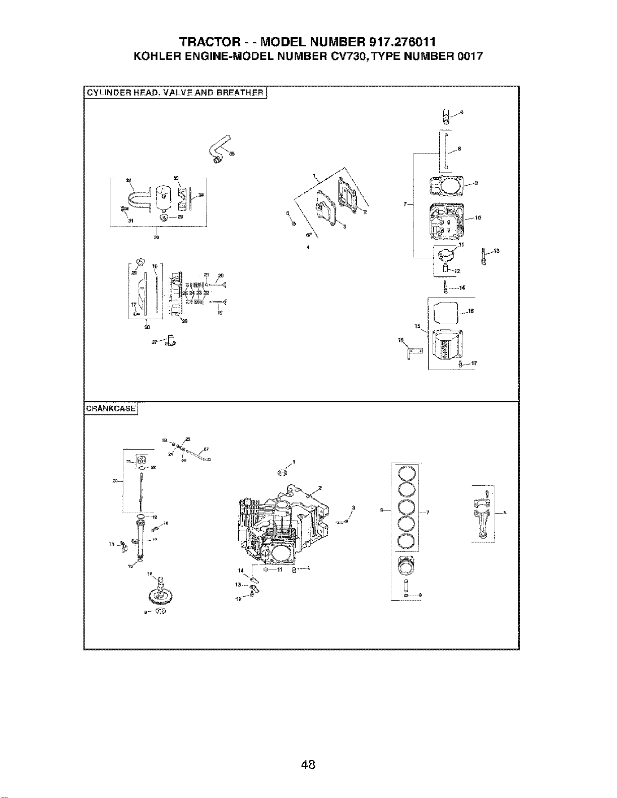
TRACTOR - - MODEL NUMBER 917.276011
KOHLER ENGINE-MODEL NUMBER CV730,TYPE NUMBER 0017
CYLINDER HEAD, VALVE AND BREATHER T
J j'iF
z,J-_
7
P
BRANKCASEJ
O _:2
10
&
go-@
/,1
@
3
/
0
0
0
[
@
8
.... 7
48

TRACTOR - - MODEL NUMBER 917.276011
KOHLER ENGINE-MODEL NUMBER CV730,TYPE NUMBER 0017
HEAD/VALVF_JBREATHER
KEY PART
NO. NO. DESCRIPTION
1.
2,
3.
4.
5,
6.
7.
8,
9.
10.
11.
12.
13.
14.
15.
16.
17.
18.
19.
20.
21.
22.
23.
24.
25.
26.
27.
28.
29.
30.
31.
32.
33.
34.
35.
24_033-03-S
24041-23S
24 096-87_S
M-645020-S
25 139 60S
25_351-01S
24_755-66 S
24_411-05-S
24041-37_S
24-318-72S
25_186-01S
24_599-01uS
12 086 16S
M-640034-S
24-755-74-S
24 153-23 S
24-086-32-S
24_445-01S
24016-01 S
24016-02S
24017-01 S
24_017-02-S
66 032-05_S
235011-S
24_089-02 S
12q 73-01_S
12_755-03-S
24318-69S
24 605 01S
24_755-76 S
25_313-03S
24_755-57 S
M-545016-S
24_445-01S
24 126-44_S
24112-12-S
24_326-55_S
CRANKCASE
KEY PART
NO. NO. DESCRIPTION
Kit, breather cover w/gasket 1.
(GlnCludes2, 3)
asket, breather 2.
Cover, breather
Screw, hex. flange 3.
4.
M6x1.0x2O (4) 5.
Plug, hex. ctsk. 1/8"
Lifter, valve (4)
Kit, valve train (Includes 8. 6.
11.12)
Rod, push (4) 7.
Gasket, cylinder head (2) 8.
Head assembly, #2 cylinder
Arm, rocker (4) 9.
Pivot, rocker arm (4)
Screw, hex. flange
M10x1.5x90 (4)
Screw, hex. flange
M6x1.0x34 (4)
Kit, valve cover - plain 10.
_ncludes 16,17)
-Ring 11.
Screw. shoulder M6xl.Ox30 12.
(4) 13.
Strap, lifting 14.
Valve, exhaust (Std.) (2)
Valve, exhaust (.25) (2) 15.
16.
Valve, intake (Std.) (2)
Valve, intake (.25) (2) 17.
SeaJ,valve stem (2) 18.
Retainer, spring (4)
Spring, valve (4) 19.
Cap, valve spring (4) 20.
Kit, retainer (4) 21.
Head assembly, #1 cylinder 22.
Liner, exhaust port (2) 23.
Kit, valve cover_ breather 24.
_lncludes 18,17,29)
rommet, rubber 25.
26.
Kit, breather separator 27.
_ncludes 29,31 _34)
crew, hex. flange
M5x0.Sxl 6 (2)
Strap, breather
Bracket, breather separator
Spacer
Hose. breather
24-032_01-S
24-294q3-S
24-380 13-S
24-067q3-S
24-067-14-S
24-874_08-S
24-874-16-S
24-108-05-S
24-018_01-S
12422-09-S
12422-13-S
12422-07-S
12422-08-S
12422-10-S
12422-11-S
12-422-12-S
24-012-16-S
52-139-09-S
M_545010_S
24-018_04-S
24-402-05-S
12-153-01 -S
24-126-19-S
12-123-04-S
M_545016S
12-153-02-S
24-038_04-S
24-755 46-S
25 153 O2-S
24-018-09-S
M-931010-S
28-032-09-S
24-468-15-S
24-144_38-S
Seal, front oil
Crankcase (USE: Mini
block 24 782 14)
Fitting
Pin, locating (6)
Connecting Rod (Std.) (2)
Connecting Rod (.25) (2)
Piston w/Ring Set (Std.)
(2) (Includes 7, 8)
Kit, piston w/ring set (.08)
Ring Set (Std. & .08) (2)
Retainer, piston pin (4)
Shim. camshaft (A.R.)
Shim. camshaft (A.R.)
Shiml camshaft (A.R.)
Shiml camshaft (A.R.)
Shim, camshaft
Shim, camshaft (A.R.)
Shim, camshaft (A.R.)
Camshaft
Plug, cup
Screw, hex. flange
M5xO.8xl0 (2)
Retainer, reed (2)
Reed, breather (2)
O-Ring, lower oil fill tube
Bracket, oil fill tube
Tube, oil fill
Screw, hex. flange
M5xO.8x16
O-Ring, upper oilfill tube
Dipstick assembly (Includes
21, 22)
Kit, oil fill cap (Includes 22)
O-Ring, dipstick
Ring, retainer
Washer, nylon (top)
Seal, governor cross shaft
Washer (bottom)
Shaft, governor cross
NOTE: All component dimensions given in U.S.
inches 1 inch = 25.4 mm
49
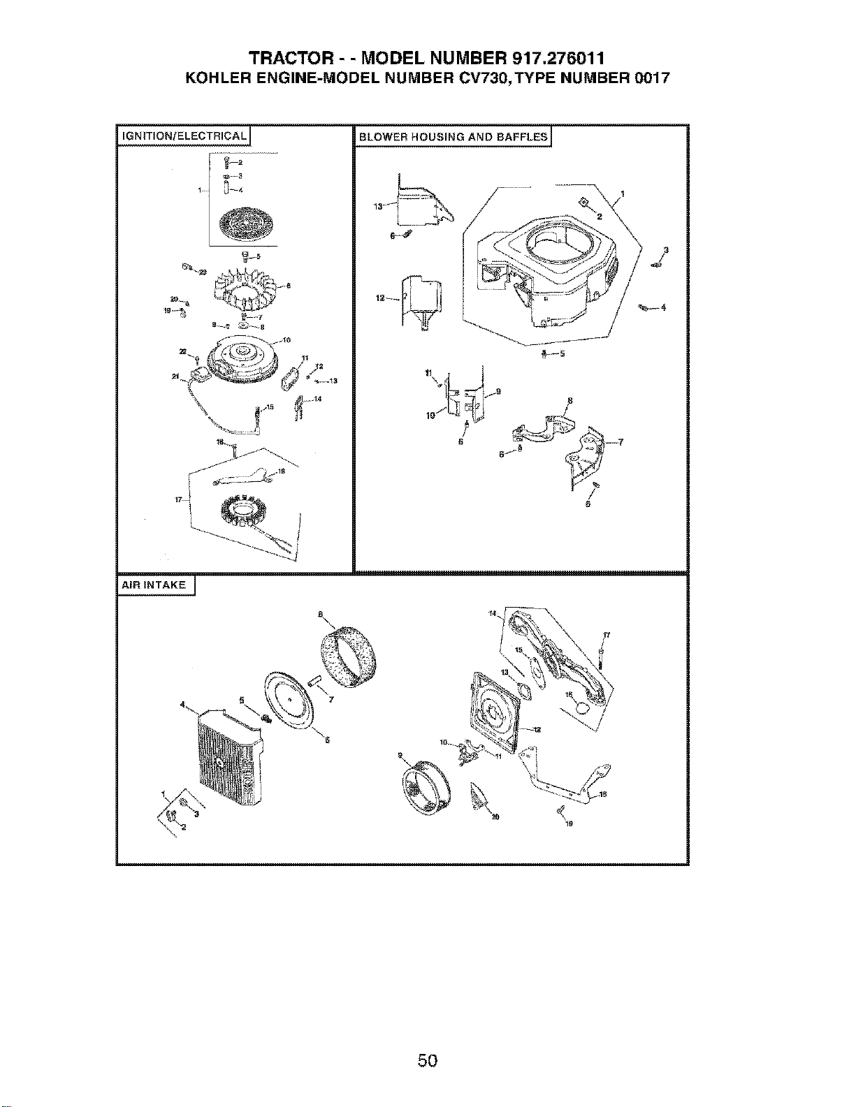
TRACTOR - - MODEL NUMBER 917.276011
KOHLER ENGINE-MODEL NUMBER CV730,TYPE NUMBER 0017
IGNIT_ON,t ELECTRICA L_
1- ;j--4
_ 44
J /'_ 18
BLOWER HOUSING AND BAFFLES i
?
AIR INTAKE I
s\
\
5O
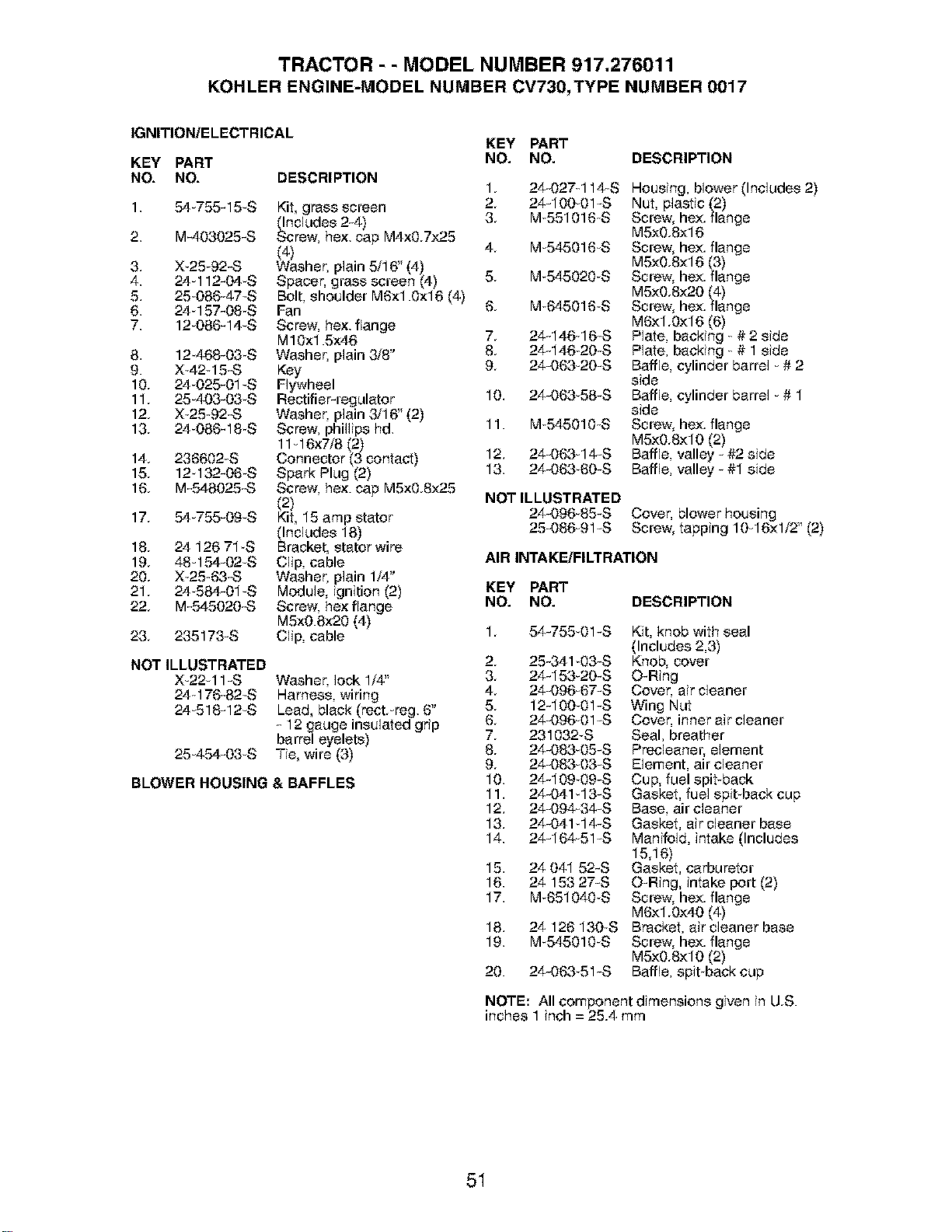
TRACTOR - - MODEL NUMBER 917.276011
KOHLERENGINE-MODELNUMBERCV730,TYPENUMBER0017
IGNITION/ELECTRICAL
KEY PART
NO. NO. DESCRIPTION
1.
2.
3,
4.
5.
6.
7.
8,
9.
10.
11.
12.
13.
14.
15.
16.
17.
18.
19.
20.
21.
22.
23.
54u755- 15uS
M-403025-S
X_25_92-S
24u112-04S
25u086-47uS
24q 57-08 S
12u086-14uS
12 468-03 S
X42 u15-S
24_025-01uS
25u403-03 S
X_25 92-S
24u086-18S
236602-S
12 132-06_S
M-548025-S
54u755-09uS
24 126 71 S
48-154-02-S
X_25 63-S
24584-01uS
M-545020-S
235173-S
Kit, grass screen
_mcludes 2-4)
craw, hex. cap M4x0.7x25
(4)
Washer, plain 5/16" (4)
Spacer. grass screen (4)
Bolt, shoulder M6x1.0x16 (4)
Fan
Screw. hex. flange
M10x1.5x46
Washer. plain 3/8"
Key
Flywheel
Rectifier-regulator
Washer, plain 3/16" (2)
Screw. phillips hd.
1116x7/8 (2)
Connector (3 contact)
Spark Plug (2)
Screw. hex. cap M5x0.8x25
(2)
Kit, 15 amp stator
(Includes 18)
Bracket, stator wire
Clip, cable
Washer, plain 1/4"
Module, ignition (2)
Screw. hex flange
M5x0.8×20 (4)
Clip, cable
NOT ILLUSTRATED
X_22u11 -S
24 176-82uS
24u518-12uS
25u454-03 S
Washer. lock 1/4"
Harness, wiring
Lead, black (rect.ureg. 6"
- 12 gauge insulated grip
barrel eyelets)
Tie, wire (3)
BLOWER HOUSING & BAFFLES
KEY PART
NO. NO. DESCRIPTION
1. 24-027u114uS Housing, blower(Includes2)
2. 24-10001-S Nut, plastic (2)
3. Mu551016 S Screw, hex.flange
M5x0.8x16
4. Mu545016S Screw, hex. flange
M5x0.ex16 (3)
5. Mu545020uS Screw, hex.flange
M5x0.ex20 (`4)
6. Mu645016 S Screw, hex.flange
M6xl.0x16 (6)
7. 24-146-16-S Plate, becking u# 2 side
8. 24-146 20-S Plate, backing u# 1 side
9. 24-063_20-S Baffle, cylinder barrel u# 2
side
10. 24-063 58-S BaffEe,cylinder barrel u# 1
side
11. Mu545010_S Screw, hex. flange
M5x0.8xl0 (2)
12. 24-063q4-S BaffEe,valley - #2 side
13. 24-063 60-S BaffEe,valley-#1 side
NOT ILLUSTRATED
24-096_85-S Cover. blower housing
25-086u91-S Screw, tapping 10 16xl/2"(2)
AIR INTAKE/FILTRATION
KEY PART
NO. NO. DESCRIPTION
1. 54-75501-S Kit, knobwith seal
(Includes 2,3)
2. 25-341 03-S Knob, cover
3. 24-153-20-S O-Ring
4. 24-096u67-S Cover, air cleaner
5. 12-100_01-S Wing Nut
6. 24-096_01-S Cover. inner air cleaner
7. 231032-S Seal, breather
8. 24-083-05-S Precleaner, element
9. 24-083-03-S Element, air cleaner
10. 24-10909-S Cup, fuelepit-back
11. 24-041 13-S Gasket, fuel spit back cup
12. 24-094u34-S Base, air cleaner
13. 24-041 14-S Gasket, aircleaner base
14. 24-164-51-S Manifold, intake (Includes
15,16)
15. 24 041 52-S Gasket, carburetor
16. 24 153 27-S O-Ring, intake port (2)
17. Mu651040S Screw, hex. flange
M6x1.0x40 (4)
18. 24 126 130S Bracket, aircleaner base
19. Mu545010uS Screw, hex. flange
M5x0.8xl0 (2)
20. 24-06351-S Baffle, spit backcup
NOTE: All component dimensions given in U.S.
inches 1 inch = 25.4 mm
51
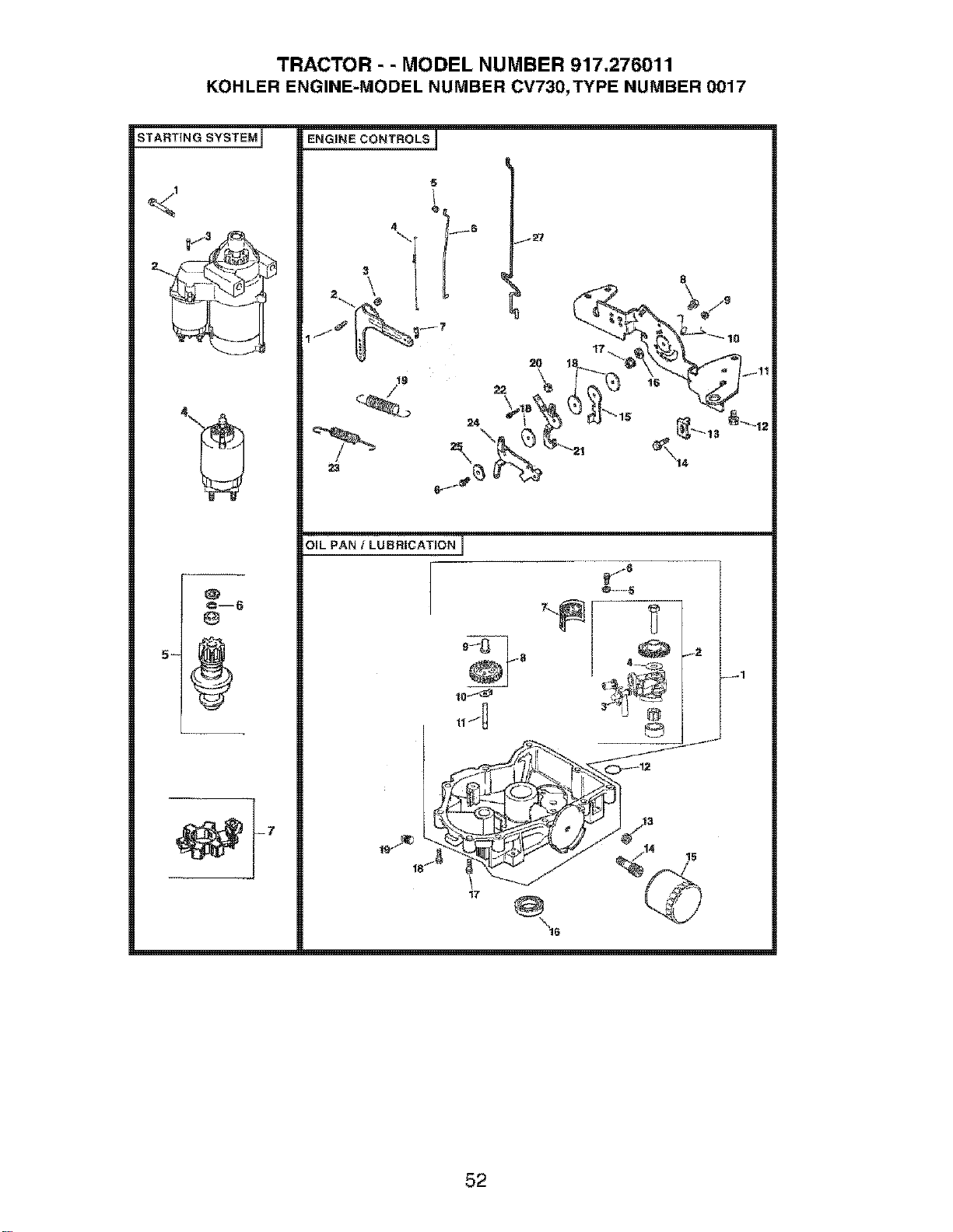
TRACTOR - - MODEL NUMBER 917.276011
KOHLER ENGINE-MODEL NUMBER CV730,TYPE NUMBER 0017
STARTING SYSTEM I
@
ENGINE CONTROLS I
5
°!
16 _Ert
OiL PAN / LU BR]CATJON J
17
52
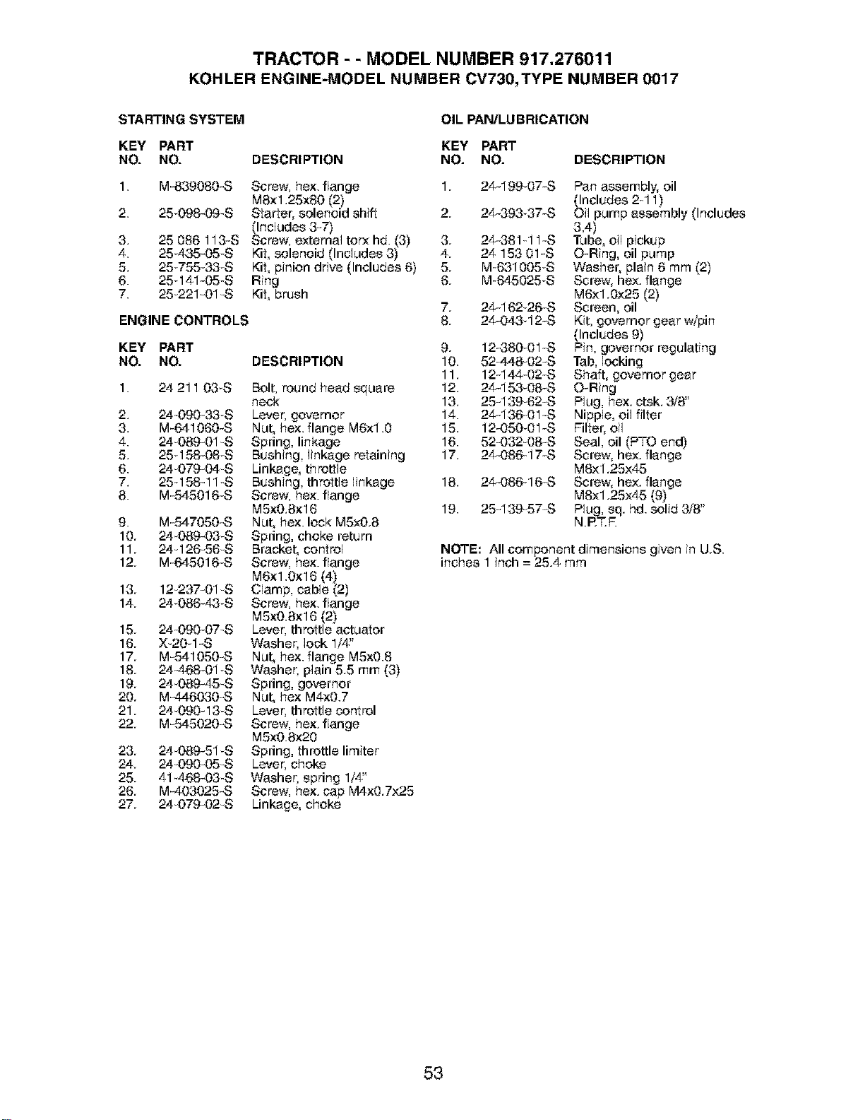
TRACTOR - - MODEL NUMBER 917.276011
KOHLERENGINE-MODELNUMBERCV730,TYPENUMBER0017
STARTING SYSTEM
KEY PART
NO. NO.
1. M-839080-S
2. 25_098-09-S
3. 25 086 113-S
4. 25-435-05 S
5. 25-755-33_S
6. 25-141-05S
7. 25-221-01 -S
ENGINE CONTROLS
KEY PART
NO. NO.
DESCRIPTION
OIL PAN/LUBRICATION
KEY PART
NO. NO.
Screw. hex. flange 1.
MSx1.25x80 (2)
Starter, solenoid shift 2.
_ncludes 3-7)
crew, external torx hd. (3) 3.
Kit, solenoid (Includes 3) 4.
Kit, pinion drive (Includes 6) 5.
Ring 6.
Kit, brush
DESCRIPTION
1. 24 211 03S Bolt, round head square
neck
2. 24 090-33 S Lever, governor
3. M-641060-S Nut, hex. flange M6xl.0
4. 24_089-01-S Spring, linkage
5. 25q 58-08_S Bushing, linkage retaining
6. 24-079-04 S Linkage, throttle
7. 25158-11 S Bushing, throttle finkage
8. M-545016-S Screw. hex. flange
M5xO.Sxl 6
9. M-547050-S Nut, he×.lock M5xO.8
10. 24089-03_S Spring, choke return
11. 24 126-56 S Bracket, control
12. M-645016-S Screw. hex. flange
M6xl .Oxl 6 (4)
13. 12237-01S Clamp. cable (2)
14. 24-086-43 S Screw. he×.flange
M5xO.Sxl 6 (2)
15. 24 090-07-S Lever. throttle actuator
16. X_20_1-S Washer. lock 1/4"
17. M-541050-S Nut, hex. flange M5xO.8
18. 24_468-01S Washer. plain 5.5 mm (3)
19. 24089-45-S Spring, governor
20. M-446030-S Nut, hex M4xO.7
21. 24 090-13 S Lever. throttle control
22. M-545020-S Screw. hex. flange
M5xO.Sx20
23. 24089-51 S Spring, throttlelimiter
24. 24 090-05-S Lever. choke
25. 41_468-03S Washer, spring 1/4"
26. M-403025-S Screw. hex. cap M4x0.7x25
27. 24-079-02-S Linkage, choke
DESCRIPTION
7.
8.
9.
10.
11.
12.
13.
14.
15.
16.
17.
18.
19.
24-199_07-S
24-393 37-S
24-381-11 -S
24 153 01-S
M-631005-S
M-645025-S
24-162-26-S
24-043 12-S
12_80_01-S
52448-02-S
12-144 02-S
24-153-08-S
25-139_62-S
24-136-01-S
12-050_01-S
52-032-08-S
24-086q7-S
24-086-16-S
25-139-57-S
Pan assembly, oil
_cludes 2-11)
pump assembly (Includes
3,4)
Tube,oil pickup
O-Ring, oil pump
Washer, plain 6 mm (2)
Screw, hex. flange
M6x1.0x25 (2)
Screen, oil
Kit, governor gear w/pin
(Includes 9)
Pin, governor regulating
Tab, locking
Shaft, governor gear
O-Ring
Plug, hex ctsk 3/8"
Nipple, oil filter
Filte£ oil
Seal, oil (PTO end)
Screw, hex. flange
M8x1.25x45
Screw, hex. flange
M8x1.25x45 (9)
Plug, sq. hd. solid 3/8"
NRT.R
NOTE: All component dimensions given in U.S.
inches 1 inch = 25.4 mm
53
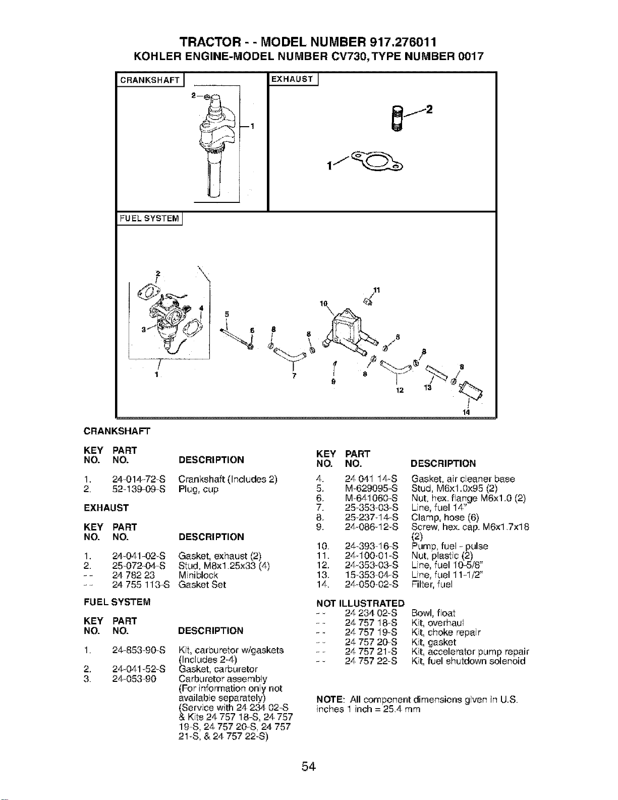
TRACTOR - - MODEL NUMBER 917.276011
KOHLER ENGINE-MODEL NUMBER CV730,TYPE NUMBER 0017
CRANKSHAFT I EXHAUSTJ
FUELSYSTEM]
/
1
14
CRANKSHAFT
KEY PART
NO. NO. DESCRIPTION
1. 24_014-72S Crankshaft (Includes2)
2. 52q 39-09_S Plug,cup
EXHAUST
KEY PART
NO. NO. DESCRIPTION
1. 24_041-02S Gasket, exhaust (2)
2. 25_072-04_S Stud, MSx1.25x33 (4)
- - 24 782 23 Miniblock
-- 24 755 113-S Gasket Set
FUEL SYSTEM
KEY PART
NO. NO. DESCRIPTION
1. 24_853_90-S
2. 24_041_52_S
3. 24_053_90
Kit, carburetor w/gaskets
_ncludes 2_4)
asket, carburetor
Carburetor assembly
(For information only not
available separately)
(Service with 24 234 02-S
& Kits 24 757 18-S, 24 757
19S, 24 757 20_S,24 757
21uS,& 24 757 22_S)
KEY PART
NO. NO. DESCRIPTION
4. 24 041 14-S Gasket, air cleaner base
5. M_629095-S Stud, M6x1.0x95 (2)
6. M_641060-S Nut, hex. flange M6x1.0 (2)
7. 2535303-S Line, fuel 14"
8. 2523714S Clamp, hose (6)
9. 24_086q 2-S Screw. hex. cap. M6x1.7x18
(2)
10. 2439316_S Pump, fuel - pulse
11. 2410001 S Nut, plastic(2) ,,
12. 24_353-03-S Line, fuel 10-5/8
13. 15 353 04_S Line, fuel 11-1/2"
14. 24_05002_S Filter, fuel
NOT ILLUSTRATED
- 24 234 02-S Bowl, float
- 24 757 18_S Kit, overhaul
- 24 757 19_S Kit, choke repair
- 24 757 20_S Kit, gasket
- _ 24 757 21uS Kit, accelerator pump repair
- _ 24 757 22_S Kit, fuel shutdown solenoid
NOTE: All component dimensions given in U.S.
inches 1 inch = 25.4 mm
54

SUGGESTED GUIDE FOR SIGHTING SLOPES FOR SAFE OPERATION
1. Fold this page along dotted line indicated above.
2. Hold page before you so that its left edge is vertically parallel to a tree
trunk or other upright structure,
3, Sight across the fold in the direction of hill slope you want to measure,
4, Compare the angle of the fold with the slope of the hill,

Your Home
For repair - in your home - of all major brand appliances,
lawn and garden equipment, or heating and cooling systems,
no matter who made it, no matter who sold it!
For the replacement parts, accessories and
owner's manuals that you need to do-it-yourself.
For Sears professional installation of home appliances
and items like garage door openers and water heaters.
1-800-4-MY-HOME ® Anytime, dayor night
(1-800-469-4663) (U.S.A. and Canada)
www.sears.com www.sears,ca
Our Home
For repair of carry-in products like vacuums, lawn equipment,
and electronics, call or go on-line for the nearest
Sears Parts and Repair Center.
1-800-488-1222 Anytime, day or night (U.S.A. only)
www.sears,com
To purchase a protection agreement (U,S,A,)
or maintenance agreement (Canada) on a product serviced by Sears:
1-800-827-6655 (USA) 1-800-361-6665 (Canada)
Para pedir servicio de reparaciSn
a domicilio, y para ordenar piezas:
1-888-SU-HOGAR sM
(1-888-784,6427)
Au Canada pour service en frangais:
1-800-LE-FOYER Mc
(1-800-5&3.6937)
www.sears.ca
SEARS
® Registered Trademark / '_ Trademark / sboService Mark of Sears, Roebuck and Co,
® Marce Registreda / M Marca de FAbrica / s_,Marca de Servicio de Sears, Roebuck and Co.
McMarque de commerce / b°DMarque d_Ipos_le de Sears, Roebuck and Co.
188068 Rev. 2 9.23.03 MH Printed in U.S.A.