Loading ...
Loading ...
Loading ...
OWNER’S MANUAL 1199797 REV 0 (6/14)
PAGE
11
OF 40
RADIANT BROILER
Install the restraint cable to an appliance mounted on casters using the following procedure:
1. Secure the restraining device bracket (item “B” in the following illustration) to a wall stud located as close as
possible to the appliance connector inlet and outlet connections. Use four #12 screws (item “C”) and plastic
anchors (item “A”) if necessary.
2. Install eye-bolt (item “F”) to a frame member on the rear of the equipment. After checking carefully behind the
frame member for adequate clearance, drill a 1/4” hole through the frame member.
3. Thread hex nut (item “G”) and slide the washer (item “H”) onto the eye-bolt. Insert the eye-bolt through the 1/4”
drilled hole and secure with a washer (item “H”) and nylon lock nut (item “I”).
4. Using the spring-loaded snap hooks, attach the restraining device to the bracket and the eye-bolt.
5. Using the cable clamp (item “D”), adjust the restraining device extended length to prevent over-bending or kinking
of the appliance connector.
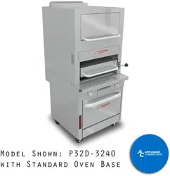
INSTALLATION
Figure 6
Installation of Casters
NOTICE
For an appliance equipped with casters, (1) the installation shall be made with a connector that complies with the
Standard for Connectors for Movable Gas Appliances, ANSI Z21.69 or Connectors for Moveable Gas Appliances,
CAN/CGA-6.16, and a quick-disconnect device that complies with the Standard for Quick-Disconnect Devices for
Use With Gas Fuel, ANSI Z21.41, or Quick Disconnect Devices for Use with Gas Fuel, CAN1-6.9, (2) adequate
means must be provided to limit the movement of the appliance without depending on the connector and the quick-
disconnect device or its associated piping to limit the appliance movement, and (3) the restraining means should be
attached to a frame member on the back of the unit.
STEP 3: ATTACH RESTRAINT
Loading ...
Loading ...
Loading ...