
Z1000
Z1000 ABS
Motorcycle
Service Manual

This quick reference guide will assist
you in locating a desired topic or pro-
cedure.
•Bend the pages back to match the
black tab of the desired chapter num-
ber with the black tab on the edge at
each table of contents page.
•Refer to the sectional table of contents
for the exact pages to locate the spe-
cific topic required.
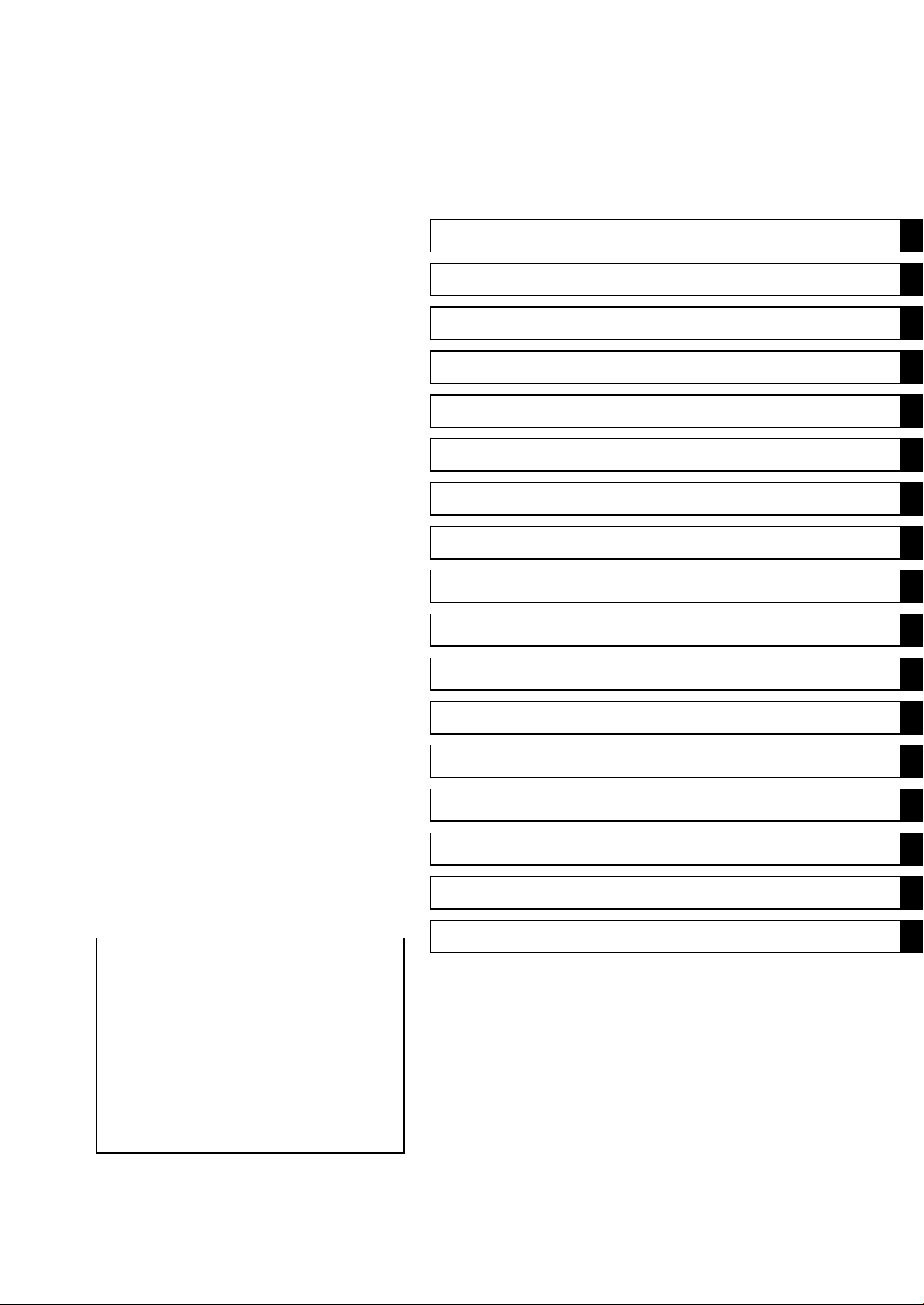
Quick Reference Guide
General Information 1 j
Periodic Maintenance 2 j
Fuel System (DFI) 3 j
Cooling System 4 j
Engine Top End 5 j
Clutch 6 j
Engine Lubrication System 7 j
Engine Removal/Installation 8 j
Crankshaft/Transmission 9 j
Wheels/Tires 10 j
Final Drive 11 j
Brakes 12 j
Suspension 13 j
Steering 14 j
Frame 15 j
Electrical System 16 j
Appendix 17 j


Z1000
Z1000 ABS
Motorcycle
Service Manual
All rights reserved. No parts of this publication may be reproduced, stored in a retrieval system, or
transmitted in any form or by any means, electronic mechanical photocopying, recording or otherwise,
without the prior written permission of Quality Assurance Division/Motorcycle & Engine Company/Kawasaki
Heavy Industries, Ltd., Japan.
No liability can be accepted for any inaccuracies or omissions in this publication, although every possible
care has been taken to make it as complete and accurate as possible.
The right is reserved to make changes at any time without prior notice and without incurring an obligation
to make such changes to products manufactured previously. See your Motorcycle dealer for the latest
information on product improvements incorporated after this publication.
All information contained in this publication is based on the latest product information available at the time
of publication. Illustrations and photographs in this publication are intended for reference use only and may
not depict actual model component parts.
© 2009 Kawasaki Heavy Industries, Ltd. 5th Edition (0) : May 11, 2012

LIST OF ABBREVIATIONS
A
ampere(s)
lb
pound(s)
ABDC after bottom dead cente
r
m
meter(s)
AC alternating current min minute(s)
ATDC after top dead center N newton(s)
BBDC before bottom dead center Pa pascal(s)
BDC bottom dead center PS horsepower
BTDC before top dead center psi pound(s) per square inch
°C degree(s) Celsius r revolution
DC direct current rpm revolution(s) per minute
F farad(s) TDC top dead center
°F degree(s) Fahrenheit TIR total indicator rea
ding
ft foot, feet
V
volt(s)
g
gram(s)
W
watt(s)
h
hour(s) Ω ohm(s)
L liter(s)
COUNTRY AND AREA CODES
AT Austria PH Philippine
AU Australia
SEA-B1
Southeast Asia B1 (with Evaporative
Emission Control System)
BR Brazil SEA-B2 Southeast Asia B2
CA Canada TH Thailand
CA
L
Ca
lifornia
US Un
ited States
CH Switzerland
WVTA
(FULL H)
WVTA Model with Honeycomb
Catalytic Converter (Full Power)
DE Germany
GB WVTA
(FULL H)
WVTA Model with Honeycomb Catalytic
Converter (Left Side Traffic, Full Power)
GB United Kingdom
WVTA
(78.2 H)
WVTA Model with Honeycomb
Catalytic Converter (78.2 Kw Power)
MY Malaysia

EMISSION CONTROL INFORMATION
To protect the environment in which we all live, Kawasaki has incorporated crankcase emis-
sion (1) and exhaust emission (2) control systems in compliance with applicable regulations of
the United States Environmental Protection Agency and California Air Resources Board. Addi-
tionally, Kawasaki has incorporated an evaporative emission control system (3) in compliance
with applicable regulations of the California Air Resources Board on vehicles sold in California
only.
1. Crankcase Emission Control System
This system eliminates the release of crankcase vapors into the atmosphere. Instead, the vapors
are routed through an oil separator to the intake side of the engine. While the engine is operating,
the vapors are drawn into combustion chamber, where they are burned along with the fuel and air
supplied by the fuel injection system.
2. Exhaust Emission Control System
This system reduces the amount of pollutants discharged into the atmosphere by the exhaust
of this motorcycle. The fuel, ignition, and exhaust systems of this motorcycle have been carefully
designed and constructed to ensure an efficient engine with low exhaust pollutant levels.
The exhaust system of this model motorcycle manufactured primarily for sale in California in-
cludes a catalytic converter system.
3. Evaporative Emission Control System
Vapors caused by fuel evaporation in the fuel system are not vented into the atmosphere. In-
stead, fuel vapors are routed into the running engine to be burned, or stored in a canister when
the engine is stopped. Liquid fuel is caught by a vapor separator and returned to the fuel tank.
The Clean Air Act, which is the Federal law covering motor vehicle pollution, contains what is
commonly referred to as the Act’s “tampering provisions”.
“Sec. 203(a) The following acts and the causing thereof are prohibited.
(3)(A) for any person to remove or render inoperative any device or element of design installed
on or in a motor vehicle or motor vehicle engine in compliance with regulations under this
title prior to its sale and delivery to the ultimate purchaser, or for any manufacturer or dealer
knowingly to remove or render inoperative any such device or element of design after such
sale and delivery to the ultimate purchaser.
(3)(B) for any person engaged in the business of repairing, servicing, selling, leasing, or trading
motor vehicles or motor vehicle engines, or who operates a fleet of motor vehicles know-
ingly to remove or render inoperative any device or element of design installed on or in a
motor vehicle or motor vehicle engine in compliance with regulations under this title follow-
ing its sale and delivery to the ultimate purchaser...”
NOTE
○
The phrase “remove or render inoperative any device or element of design” has been generally
interpreted as follows.
1. Tampering does not include the temporary removal or rendering inoperative of de-
vices or elements of design in order to perform maintenance.
2. Tampering could include.
a.Maladjustment of vehicle components such that the emission standards are ex-
ceeded.
b.Use of replacement parts or accessories which adversely affect the performance
or durability of the motorcycle.
c.Addition of components or accessories that result in the vehicle exceeding the stan-
dards.
d.Permanently removing, disconnecting, or rendering inoperative any component or
element of design of the emission control systems.
WE RECOMMEND THAT ALL DEALERS OBSERVE THESE PROVISIONS OF FEDERAL
LAW, THE VIOLATION OF WHICH IS PUNISHABLE BY CIVIL PENALTIES NOT EXCEEDING
$10 000 PER VIOLATION.

TAMPERING WITH NOISE CONTROL SYSTEM PROHIBITED
Federal law prohibits the following acts or the causing thereof. (1) The removal or rendering
inoperative by any person other than for purposes of maintenance, repair, or replacement, of any
device or element of design incorporated into any new vehicle for the purpose of noise control
prior to its sale or delivery to the ultimate purchaser or while it is in use, or (2) the use of the
vehicle after such device or element of design has been removed or rendered inoperative by
any person.
Among those acts presumed to constitute tampering are the acts listed below.
•
Replacement of the original exhaust system or muffler with a component not in compliance
with Federal regulations.
•
Removal of the muffler(s) or any internal portion of the muffler(s).
•
Removal of the air box or air box cover.
•
Modifications to the muffler(s) or air intake system by cutting, drilling, or other means if such
modifications result in increased noise levels.
Foreword
This manual is designed primarily for use by
trained mechanics in a properly equipped shop.
However, it contains enough detail and basic in-
formation to make it useful to the owner who de-
sires to perform his own basic maintenance and
repair work. A basic knowledge of mechanics,
the proper use of tools, and workshop proce-
dures must be understood in order to carry out
maintenance and repair satisfactorily. When-
ever the owner has insufficient experience or
doubts his ability to do the work, all adjust-
ments, maintenance, and repair should be car-
ried out only by qualified mechanics.
In order to perform the work efficiently and
to avoid costly mistakes, read the text, thor-
oughly familiarize yourself with the procedures
before starting work, and then do the work care-
fully in a clean area. Whenever special tools or
equipment are specified, do not use makeshift
tools or equipment. Precision measurements
can only be made if the proper instruments are
used, and the use of substitute tools may ad-
versely affect safe operation.
For the duration of the warranty period,
we recommend that all repairs and scheduled
maintenance be performed in accordance with
this service manual. Any owner maintenance or
repair procedure not performed in accordance
with this manual may void the warranty.
To get the longest life out of your vehicle.
•
Follow the Periodic Maintenance Chart in the
Service Manual.
•
Be alert for problems and non-scheduled
maintenance.
•
Use proper tools and genuine Kawasaki Mo-
torcycle parts. Special tools, gauges, and
testers that are necessary when servicing
Kawasaki motorcycles are introduced by the
Service Manual. Genuine parts provided as
spare parts are listed in the Parts Catalog.
•
Follow the procedures in this manual care-
fully. Don’t take shortcuts.
•
Remember to keep complete records of main-
tenance and repair with dates and any new
parts installed.
How to Use This Manual
In this manual, the product is divided into
its major systems and these systems make up
the manual’s chapters. The Quick Reference
Guide shows you all of the product’s system
and assists in locating their chapters. Each
chapter in turn has its own comprehensive Ta-
ble of Contents.
For example, if you want ignition coil informa-
tion, use the Quick Reference Guide to locate
the Electrical System chapter. Then, use the
Table of Contents on the first page of the chap-
ter to find the Ignition Coil section.
Whenever you see symbols, heed their in-
structions! Always follow safe operating and
maintenance practices.
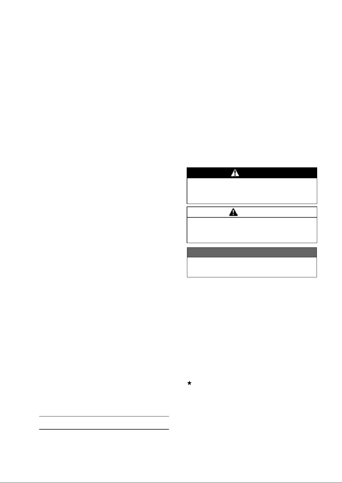
DANGER
DANGER indicates a hazardous situa-
tion which, if not avoided, will result in
death or serious injury.
WARNING
WARNING indicates a hazardous situa-
tion which, if not avoided, could result
in death or serious injury.
NOTICE
NOTICE is used to address practices not
related to personal injury.
This manual contains four more symbols
which will help you distinguish different types
of information.
NOTE
○
This note symbol indicates points of par-
ticular interest for more efficient and con-
venient operation.
•
Indicates a procedural step or work to be
done.
○
Indicates a procedural sub-step or how to do
the work of the procedural step it follows. It
also precedes the text of a NOTE.
Indicates a conditional step or what action to
take based on the results of the test or inspec-
tion in the procedural step or sub-step it fol-
lows.
In most chapters an exploded view illustration
of the system components follows the Table of
Contents. In these illustrations you will find the
instructions indicating which parts require spec-
ified tightening torque, oil, grease or a locking
agent during assembly.


GENERAL INFORMATION 1-1
1
General Information
Table of Contents
Before Servicing ..................................................................................................................... 1-2
Model Identification................................................................................................................. 1-7
General Specifications............................................................................................................ 1-10
Unit Conversion Table ............................................................................................................ 1-13
1-2 GENERAL INFORMATION
Before Servicing
Before starting to perform an inspection service or carry out a disassembly and reassembly opera-
tion on a motorcycle, read the precautions given below. To facilitate actual operations, notes, illustra-
tions, photographs, cautions, and detailed descriptions have been included in each chapter wherever
necessary. This section explains the items that require particular attention during the removal and
reinstallation or disassembly and reassembly of general parts.
Especially note the following.
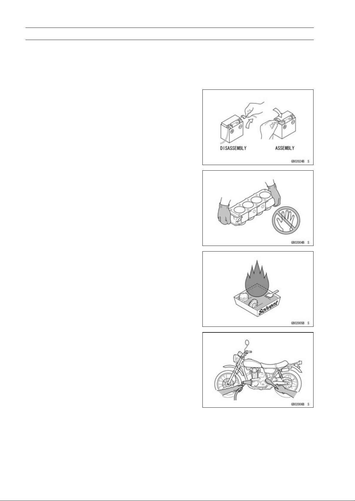
Battery Ground
Before completing any service on the motorcycle, discon-
nect the battery cables from the battery to prevent the en-
gine from accidentally turning over. Disconnect the ground
cable (–) first and then the positive (+). When completed
with the service, first connect the positive (+) cable to the
positive (+) terminal of the battery then the negative (–) ca-
ble to the negative terminal.
Edges of Parts
Lift large or heavy parts wearing gloves to prevent injury
from possible sharp edges on the parts.
Solvent
Use a high flash-point solvent when cleaning parts. High
flash-point solvent should be used according to directions
of the solvent manufacturer.
Cleaning Vehicle before Disassembly
Clean the vehicle thoroughly before disassembly. Dirt or
other foreign materials entering into sealed areas during ve-
hicle disassembly can cause excessive wear and decrease
performance of the vehicle.
GENERAL INFORMATION 1-3
Before Servicing
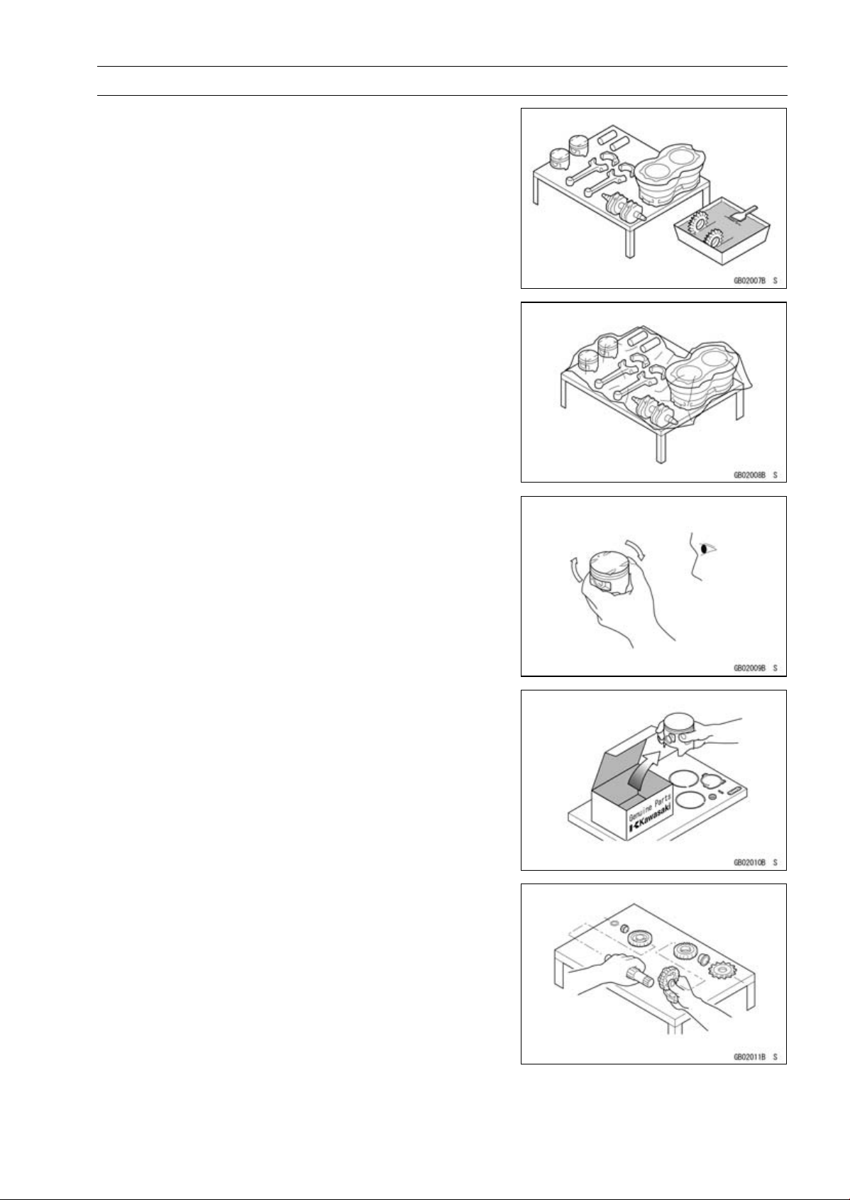
Arrangement and Cleaning of Removed Parts
Disassembled parts are easy to confuse. Arrange the
parts according to the order the parts were disassembled
and clean the parts in order prior to assembly.
Storage of Removed Parts
After all the parts including subassembly parts have been
cleaned, store the parts in a clean area. Put a clean cloth
or plastic sheet over the parts to protect from any foreign
materials that may collect before re-assembly.
Inspection
Reuse of worn or damaged parts may lead to serious ac-
cident. Visually inspect removed parts for corrosion, discol-
oration, or other damage. Refer to the appropriate sections
of this manual for service limits on individual parts. Replace
the parts if any damage has been found or if the part is be-
yond its service limit.
Replacement Parts
Replacement parts must be KAWASAKI genuine or
recommended by KAWASAKI. Gaskets, O-rings, oil seals,
grease seals, circlips, cotter pins or self-locking nuts must
be replaced with new ones whenever disassembled.
Assembly Order
In most cases assembly order is the reverse of disassem-
bly, however, if assembly order is provided in this Service
Manual, follow the procedures given.
1-4 GENERAL INFORMATION
Before Servicing
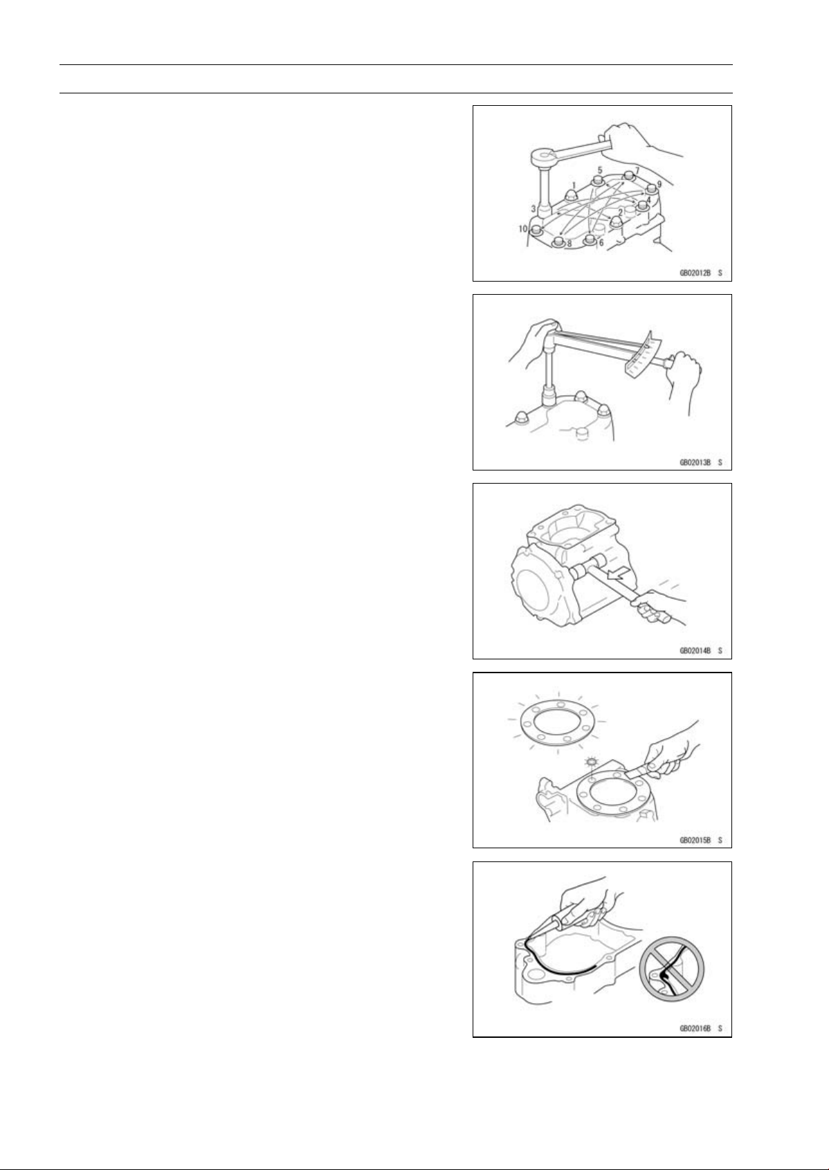
Tightening Sequence
Generally, when installing a part with several bolts, nuts,
or screws, start them all in their holes and tighten them to
a snug fit. Then tighten them according to the specified se-
quence to prevent case warpage or deformation which can
lead to malfunction. Conversely when loosening the bolts,
nuts, or screws, first loosen all of them by about a quar-
ter turn and then remove them. If the specified tightening
sequence is not indicated, tighten the fasteners alternating
diagonally.
Tightening Torque
Incorrect torque applied to a bolt, nut, or screw may
lead to serious damage. Tighten fasteners to the specified
torque using a good quality torque wrench.
Force
Use common sense during disassembly and assembly,
excessive force can cause expensive or hard to repair dam-
age. When necessary, remove screws that have a non
-permanent locking agent applied using an impact driver.
Use a plastic-faced mallet whenever tapping is necessary.
Gasket, O-ring
Hardening, shrinkage, or damage of both gaskets and
O-rings after disassembly can reduce sealing performance.
Remove old gaskets and clean the sealing surfaces thor-
oughly so that no gasket material or other material remains.
Install the new gaskets and replace the used O-rings when
re-assembling.
Liquid Gasket, Non-permanent Locking Agent
For applications that require Liquid Gasket or a
Non-permanent Locking Agent, clean the surfaces so
that no oil residue remains before applying liquid gasket or
non-permanent locking agent. Do not apply them exces-
sively. Excessive application can clog oil passages and
cause serious damage.
GENERAL INFORMATION 1-5
Before Servicing
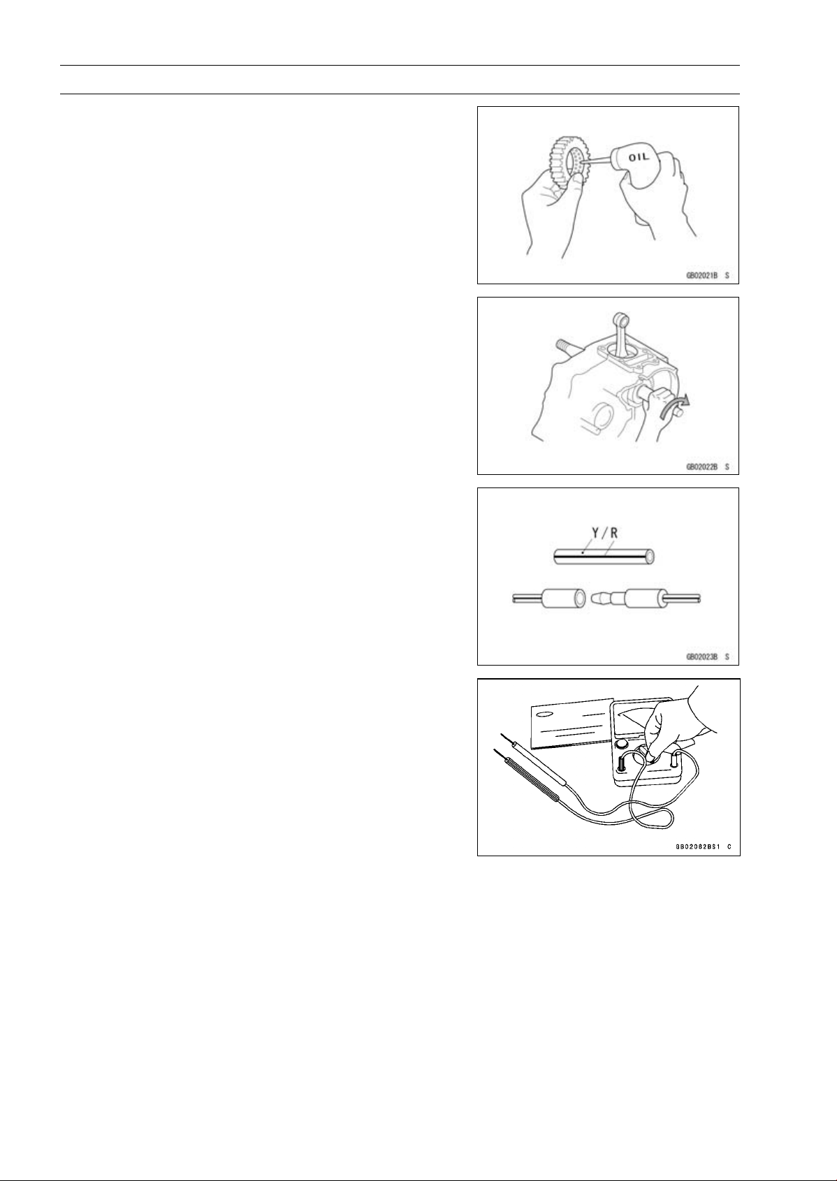
Press
For items such as bearings or oil seals that must be
pressed into place, apply small amount of oil to the con-
tact area. Be sure to maintain proper alignment and use
smooth movements when installing.
Ball Bearing and Needle Bearing
Do not remove pressed ball or needle unless removal is
absolutely necessary. Replace with new ones whenever
removed. Press bearings with the manufacturer and size
marks facing out. Press the bearing into place by putting
pressure on the correct bearing race as shown.
Pressing the incorrect race can cause pressure between
the inner and outer race and result in bearing damage.
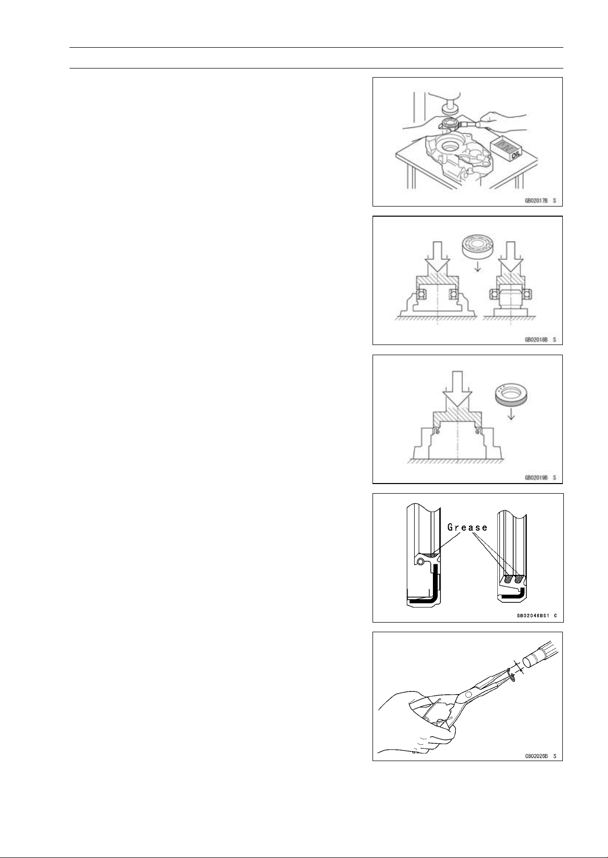
Oil Seal, Grease Seal
Do not remove pressed oil or grease seals unless removal
is necessary. Replace with new ones whenever removed.
Press new oil seals with manufacture and size marks facing
out. Make sure the seal is aligned properly when installing.
Apply specified grease to the lip of seal before installing
the seal.
Circlips, Cotter Pins
Replace the circlips or cotter pins that were removed with
new ones. Take care not to open the clip excessively when
installing to prevent deformation.
1-6 GENERAL INFORMATION
Before Servicing
Lubrication
It is important to lubricate rotating or sliding parts during
assembly to minimize wear during initial operation. Lubri-
cation points are called out throughout this manual, apply
the specific oil or grease as specified.
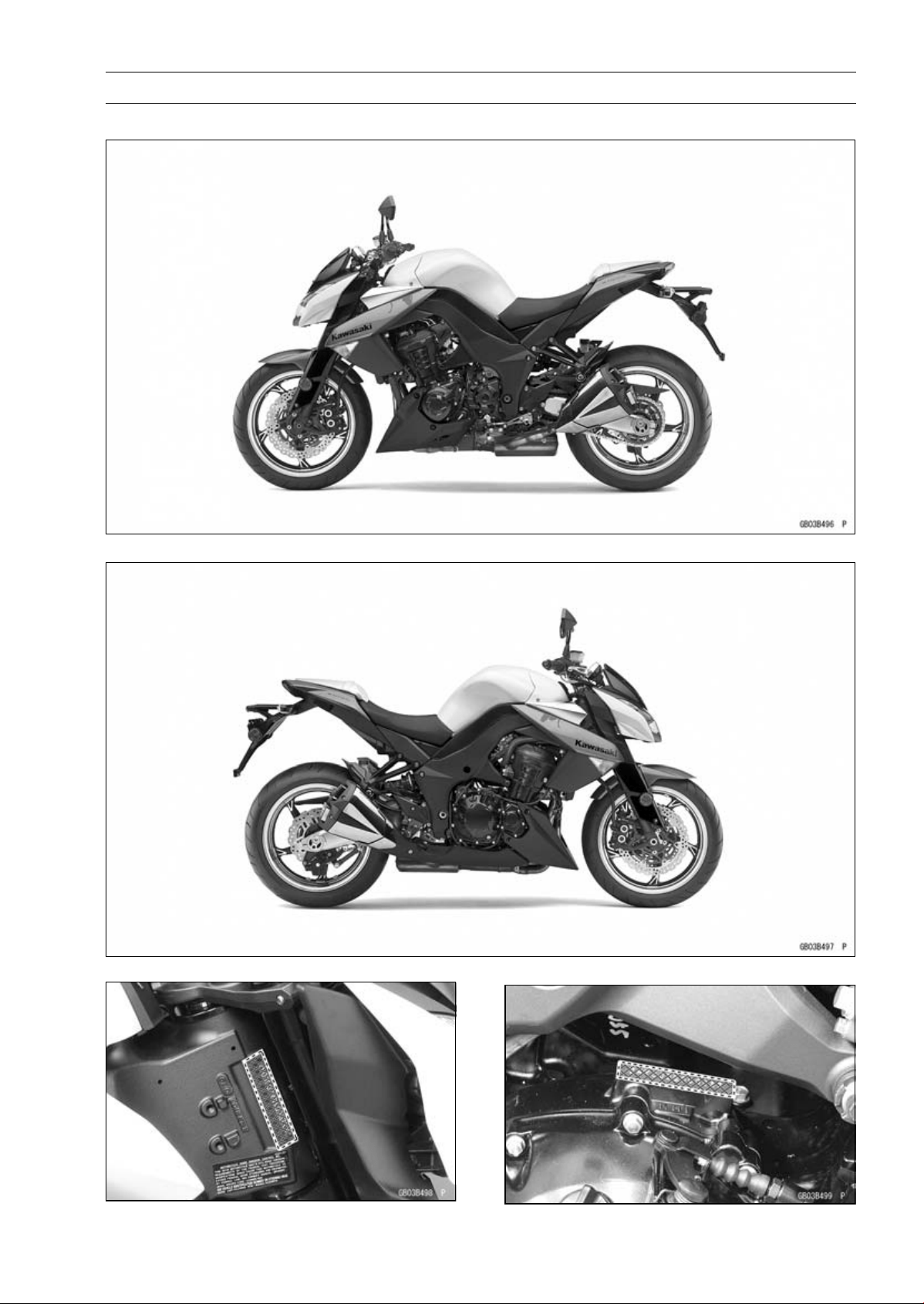
Direction of Engine Rotation
When rotating the crankshaft by hand, the free play
amount of rotating direction will affect the adjustment. Ro-
tate the crankshaft to positive direction (clockwise viewed
from output side).
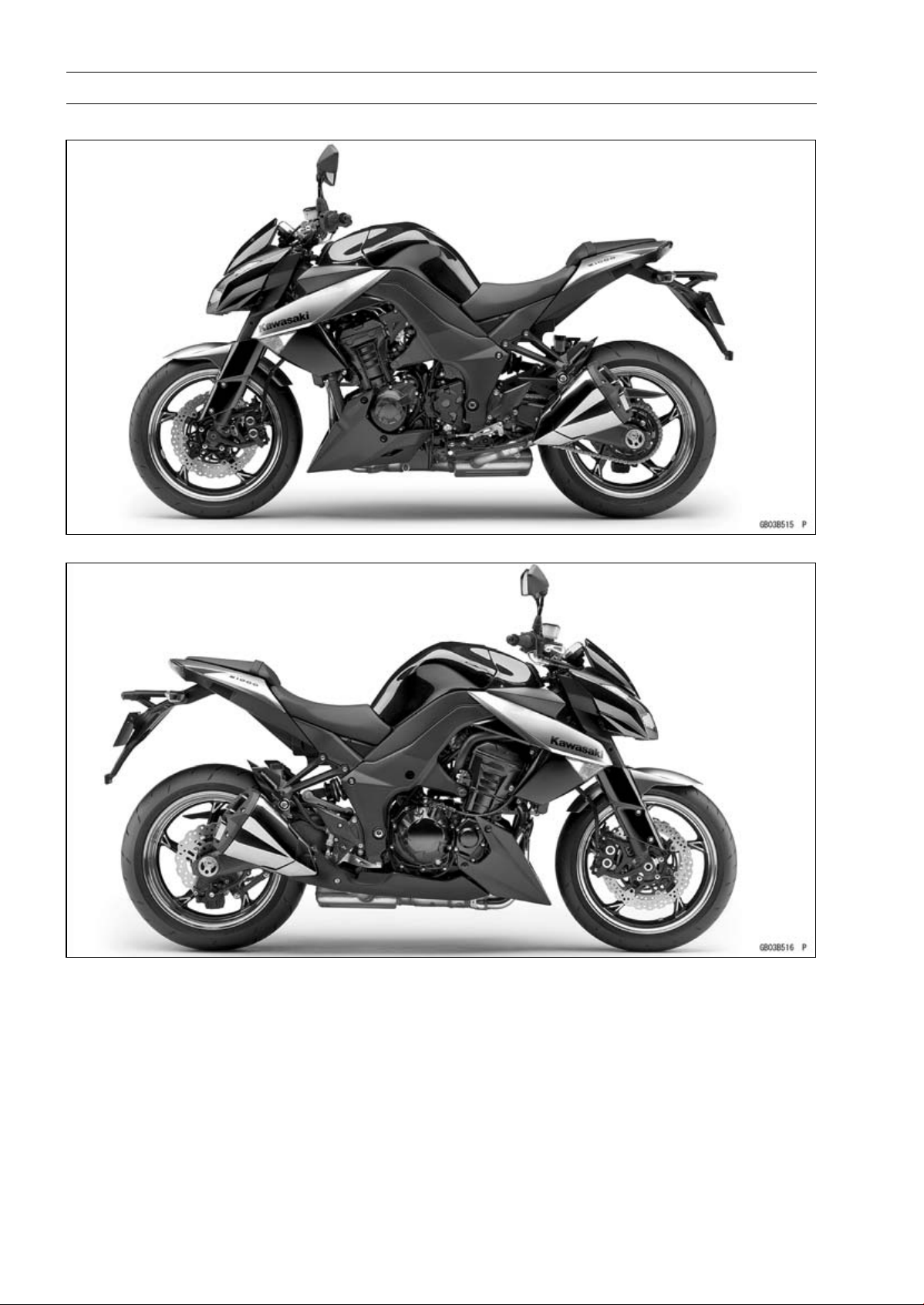
Electrical Wires
A two-color wire is identified first by the primary color and
then the stripe color. Unless instructed otherwise, electrical
wires must be connected to those of the same color.
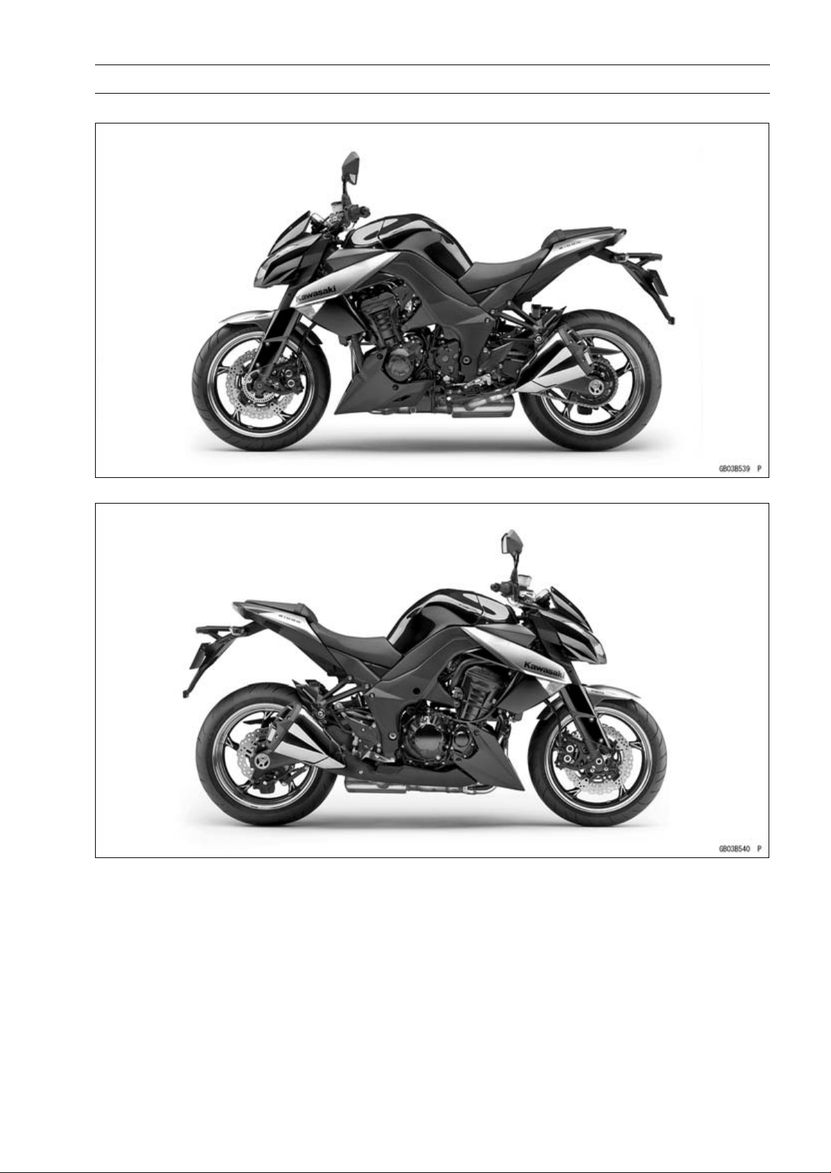
Instrument
Use a meter that has enough accuracy for an accurate
measurement. Read the manufacture’s instructions thor-
oughly before using the meter. Incorrect values may lead
to improper adjustments.
GENERAL INFORMATION 1-7
Model Identification
ZR1000DA (United States and Canada) Left Side View
ZR1000DA (United States and Canada) Right Side View
Frame Number Engine Number
1-8 GENERAL INFORMATION
Model Identification
ZR1000DA (Europe) Left Side View
ZR1000DA (Europe) Right Side View
GENERAL INFORMATION 1-9
Model Identification
ZR1000EA Left Side View
ZR1000EA Right Side View

1-10 GENERAL INFORMATION
General Specifications
Items ZR1000DA ∼ DD/EA ∼ ED
Dimensions
Overall Length 2 095 mm (82.48 in.)
Overall Width 805 mm (31.7 in.)
Overall Height 1 085 mm (42.72 in.)
Wheelbase
1 440 mm (56.69 in.)
Road Clearance 140 mm (5.51 in.)
Seat Height 815 mm (32.1 in.)
Curb Mass:
ZR1000D 218 kg (481 lb)
ZR1000E 221 kg (487 lb)
Front:
ZR1000D 111kg(245lb)
ZR1000E 112 kg (247 lb)
Rear:
ZR1000D
107 kg (236 lb)
ZR1000E
109 kg (240.2 lb)
Fuel Tank Capacit
y
15 L (4.0 US gal.)
Performance
Minimum Turning Radius 3.0 m (9.8 ft)
Engine
Type
4-stroke, DOHC, 4-cylinder
Cooling System
Liquid-cooled
Bore and Stroke 77.0 × 56.0 mm (3
.03 × 2.20 in.)
Displacement 1043cm³(63.64cuin.)
Compression Ratio 11.8 : 1
Maximum Horsepower 101.5 kW (138 PS) @9 600 r/min (rpm)
(MY, TH, SEA-B1/B2) 100 kW (136 PS) @9 000 r/min (rpm)
(WVTA (78.2 H)) 78.2 kW (106 PS) @9 100 r/min (rpm)
(CA, US) – – –
Maximum Torque 110 N·m (11.2 kgf·m, 81.1 ft·lb) @7 800 r/min (rpm)
(WVTA (78.2 H)) 95 N·m (9.7 kgf·m, 70 ft·lb) @7 500 r/min (rpm)
(CA, US) – – –
Carburetion System FI (Fuel Injection) KEIHIN TTK38 × 4
Starting System Electric starter
Ignition System Battery and coil (transistorized)
Timing Advance Electronically advanced (digital igniter)
Ignition Timing From 10° BTDC @1 100 r/min (rpm) to 40.2° BTDC
@5 200 r/min (rpm)
Spark Plug NGK CR9EIA-9
Cylinder Numbering Method Left to right, 1-2-3-4
Firing Orde
r
1-2-4-3
Valve Timing:
Intake:
Open 31° BTDC
Close 65° ABDC

GENERAL INFORMATION 1-11
General Specifications
Items ZR1000DA ∼ DD/EA ∼ ED
Duration 276°
Exhaust:
Open 58° BBDC
Close 18° ATDC
Duration 256°
Lubrication System Forced lubrication (wet sump)
Engine Oil:
Type
API SG, SH, SJ, SL or SM with JASO MA, MA1 or MA2
Viscosity
SAE 10W-40
Capacity 4.0 L (4.2 US qt)
Drive Train
Primary Reduction System:
Type Gear
Reduction Ratio
1.627 (83/51)
Clutch Type
Wet multi disc
Transmission:
Type 6-speed, constant mesh, return shift
Gear Ratios:
1st 2.600 (39/15)
2nd
1.950 (39/20)
3rd
1.600 (24/15)
4th
1.389 (25/18)
5th 1.238 (26/21)
6th 1.136 (25/22)
Final Drive System:
Type Chain drive
Reduction Ratio 2.800 (42/15)
Overall Drive Ratio 5.178 @Top gear
Frame
Type Tubular, diamond
Caster (Rake Angle) 24.5°
Trail
103 mm (4.06 in.)
Front Tire:
Type Tubeless
Size 120/70 ZR17 M/C (58W)
Rim Size J17M/C × MT3.50
Rear Tire:
Type Tubeless
Size 190/50 ZR17 M/C (73W)
Rim Size J17M/C × MT6.00
Front Suspension:
Type Telescopic fork (upside-down)
Wheel Travel 120 mm (4.72 in.)

1-12 GENERAL INFORMATION
General Specifications
Items ZR1000DA ∼ DD/EA ∼ ED
Rear Suspension:
Type Swingarm
Wheel Travel 138 mm (5.43 in.)
Brake Type:
Front Dual discs
Rear Single disc
Electrical Equipment
Battery 12 V 8 Ah
Headlight:
Type Semi-sealed beam
Bulb 12 V 55 W × 2/55 W (Hi/Lo)
Tail/Brake Light LED
Alternator:
Type Three-phase AC
Specifications are subject to change without notice, and may not apply to every country.
GENERAL INFORMATION 1-13
Unit Conversion Table
Prefixes for Units:
Prefix Symbol Power
mega M × 1 000 000
kilo k ×1000
centi c ×0.01
milli m × 0.001
micro µ × 0.000001
Units of Mass:
kg ×2.205=lb
g × 0.03527 = oz
Units of Volume:
L × 0.2642 = gal (US)
L × 0.2200 = gal (IMP)
L × 1.057 =
qt (US)
L × 0.8799 =
qt (IMP)
L × 2.113 = pint (US)
L × 1.816 = pint (IMP)
mL × 0.03381 = oz (US)
mL × 0.02816 = oz (IMP)
mL × 0.06102 = cu in
Units of Force:
N × 0.1020 = kg
N × 0.2248 = lb
kg ×9.807=N
kg ×2.205=lb
Units of Length:
km × 0.6214 = mile
m × 3.281 = ft
mm × 0.03937 = in
Units of Torque:
N·m × 0.1020 = kgf·m
N·m × 0.7376 = ft·lb
N·m × 8.851 = in·lb
kgf·m × 9.807 = N·m
kgf·m × 7.233 = ft·lb
kgf·m × 86.80 = in·lb
Units of Pressure:
kPa × 0.01020 = kgf/cm²
kPa × 0.1450 = psi
kPa × 0.7501 = cmHg
kgf/cm² × 98.07 = kPa
kgf/cm² × 14.22 = psi
cmHg×1.333=kPa
Units of Speed:
km/h
× 0.6214 = mph
Units of Power:
kW ×1.360=PS
kW ×1.341=HP
PS
× 0.7355 = kW
PS × 0.9863 = HP
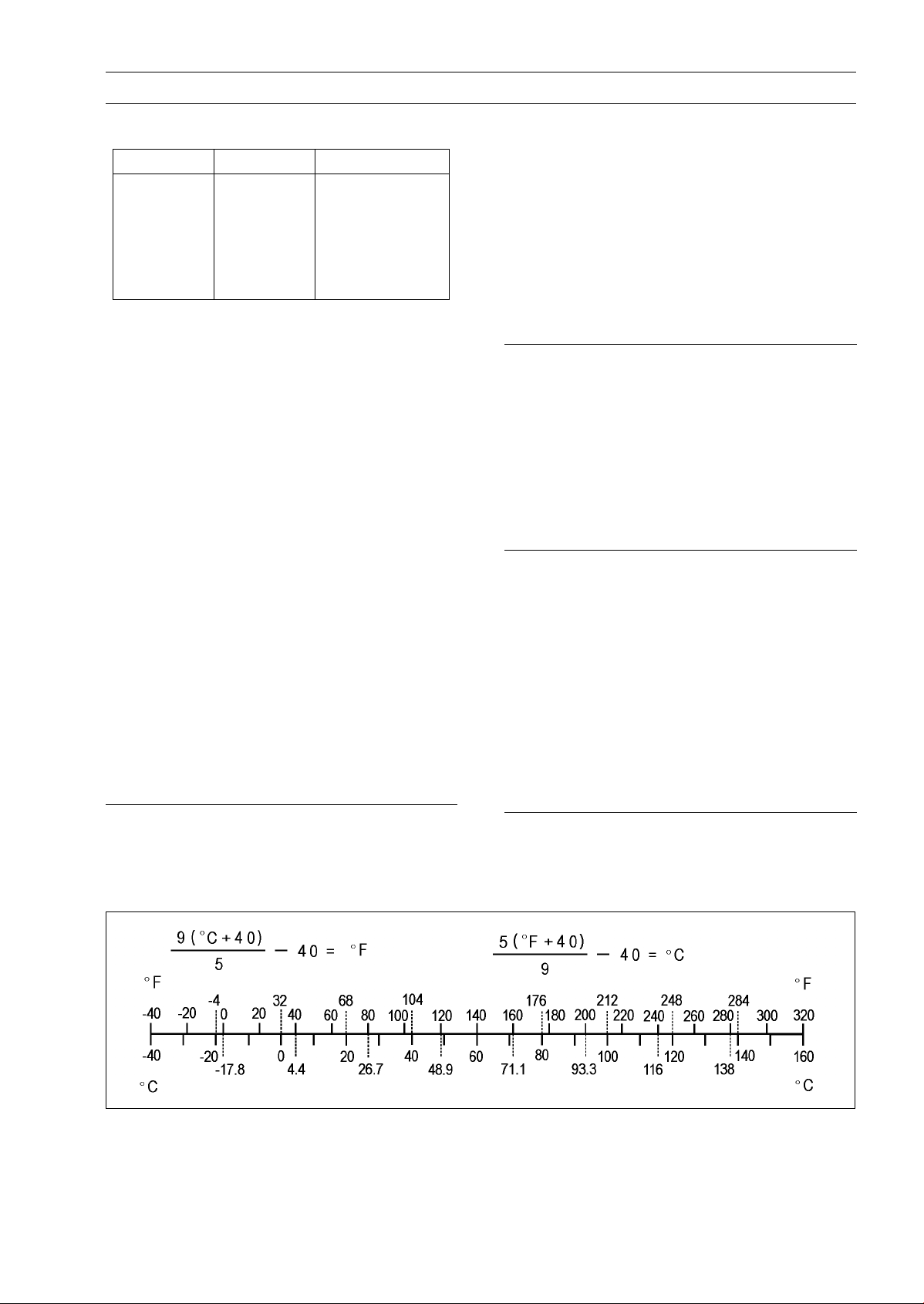
Units of Temperature:


PERIODIC MAINTENANCE 2-1
2
Periodic Maintenance
Table of Contents
Periodic Maintenance Chart ................................................................................................... 2-3
Torque and Locking Agent...................................................................................................... 2-7
Specifications ......................................................................................................................... 2-12
Special Tools .......................................................................................................................... 2-14
Periodic Maintenance Procedures.......................................................................................... 2-15
Fuel System (DFI)................................................................................................................ 2-15
Throttle Control System Inspection................................................................................... 2-15
Engine Vacuum Synchronization Inspection..................................................................... 2-15
Idle Speed Inspection ....................................................................................................... 2-19
Idle Speed Adjustment...................................................................................................... 2-20
Fuel Hose Inspection (fuel leak, damage, installation condition)...................................... 2-20
Evaporative Emission Control System (CAL, SEA-B1 and TH Models) Inspection.......... 2-21
Cooling System.................................................................................................................... 2-22
Coolant Level Inspection................................................................................................... 2-22
Radiator Hose and Pipe Inspection (coolant leak, damage, installation condition) .......... 2-22
Engine Top End ................................................................................................................... 2-23
Valve Clearance Inspection .............................................................................................. 2-23
Valve Clearance Adjustment............................................................................................. 2-24
Air Suction System Damage Inspection............................................................................ 2-28
Clutch................................................................................................................................... 2-29
Clutch Operation Inspection.............................................................................................. 2-29
Wheels/Tires........................................................................................................................ 2-30
Air Pressure Inspection..................................................................................................... 2-30
Wheel/Tire Damage Inspection......................................................................................... 2-30
Tire Tread Wear Inspection............................................................................................... 2-30
Wheel Bearing Damage Inspection .................................................................................. 2-31
Final Drive............................................................................................................................ 2-32
Drive Chain Lubrication Condition Inspection................................................................... 2-32
Drive Chain Slack Inspection ............................................................................................ 2-32
Drive Chain Slack Adjustment .......................................................................................... 2-33
Wheel Alignment Inspection ............................................................................................. 2-33
Wheel Alignment Adjustment............................................................................................ 2-33
Drive Chain Wear Inspection ............................................................................................ 2-34
Chain Guide Wear Inspection ........................................................................................... 2-34
Brakes.................................................................................................................................. 2-35
Brake Fluid Leak (Brake Hose and Pipe) Inspection ........................................................ 2-35
Brake Hose and Pipe Damage and Installation Condition Inspection............................... 2-36
Brake Operation Inspection .............................................................................................. 2-36
Brake Fluid Level Inspection............................................................................................. 2-36
Brake Pad Wear Inspection .............................................................................................. 2-37
Brake Light Switch Operation Inspection.......................................................................... 2-38
Suspension.......................................................................................................................... 2-39
Front Forks/Rear Shock Absorber Operation Inspection.................................................. 2-39
Front Fork Oil Leak Inspection.......................................................................................... 2-39
Rear Shock Absorber Oil Leak Inspection........................................................................ 2-39
Rocker Arm Operation Inspection..................................................................................... 2-39
Tie-Rod Operation Inspection ........................................................................................... 2-40
Steering ............................................................................................................................... 2-40
Steering Play Inspection ................................................................................................... 2-40
Steering Play Adjustment.................................................................................................. 2-40

2-2 PERIODIC MAINTENANCE
Steering Stem Bearing Lubrication ................................................................................... 2-42
Electrical System ................................................................................................................. 2-43
Lights and Switches Operation Inspection........................................................................ 2-43
Headlight Aiming Inspection ............................................................................................. 2-45
Headlight Aiming Adjustment............................................................................................ 2-45
Sidestand Switch Operation Inspection ............................................................................ 2-46
Engine Stop Switch Operation Inspection......................................................................... 2-47
Others.................................................................................................................................. 2-48
Chassis Parts Lubrication ................................................................................................. 2-48
Bolts, Nuts and Fasteners Tightness Inspection............................................................... 2-50
Replacement Parts .............................................................................................................. 2-51
Air Cleaner Element Replacement.................................................................................... 2-51
Fuel Hose Replacement ................................................................................................... 2-51
Coolant Change................................................................................................................ 2-53
Radiator Hose and O-ring Replacement........................................................................... 2-56
Engine Oil Change............................................................................................................ 2-57
Oil Filter Replacement ...................................................................................................... 2-57
Brake Hose Replacement................................................................................................. 2-58
Brake Fluid Change .......................................................................................................... 2-60
Master Cylinder Rubber Parts Replacement .................................................................... 2-61
Caliper Rubber Parts Replacement .................................................................................. 2-62
Spark Plug Replacement .................................................................................................. 2-66
PERIODIC MAINTENANCE 2-3
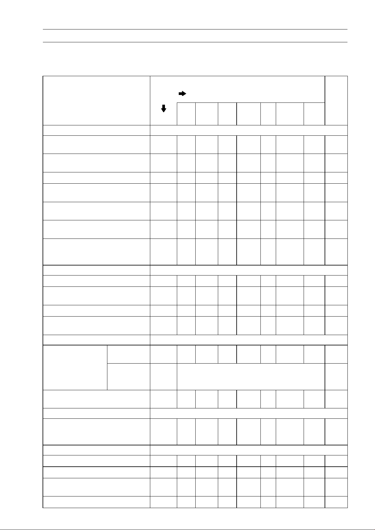
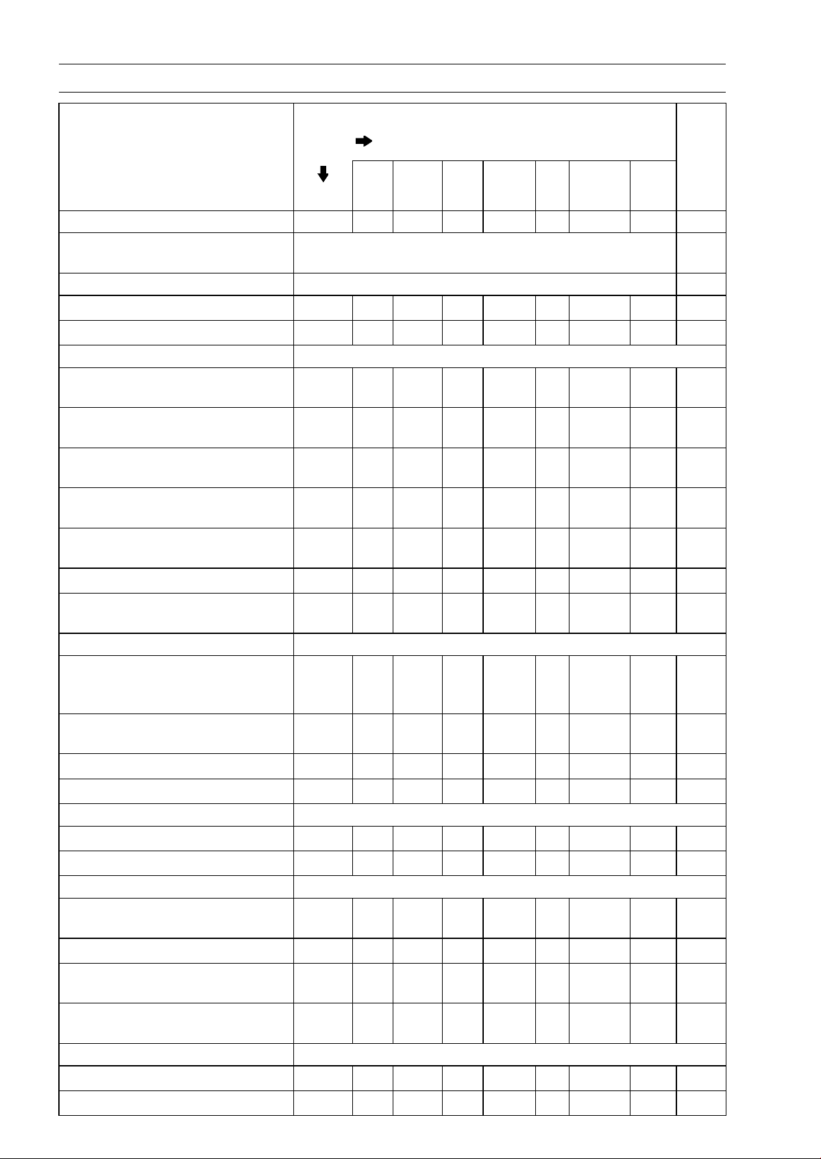
Periodic Maintenance Chart
The scheduled maintenance must be done in accordance with this chart to keep the motorcycle in
good running condition.The initial maintenance is vitally important and must not be neglected.
Periodic Inspection
FREQUENCY Whichever
comes
first
* ODOMETER READING
× 1 000 km
(× 1 000 mile)
1 6 12 18 24 30 36
ITEM Every (0.6) (3.75) (7.5) (11.25) (15) (18.75) (22.5)
See
Page
Fuel System
Throttle control system (play,
smooth return, no drag) - inspect
year
• • • •
2-15
Engine vacuum synchronization -
inspect
• • •
2-15
Idle speed - inspect
• • • •
2-19
Fuel leak (fuel hose and pipe) -
inspect
year
• • • •
2-20
Fuel hose and pipe damage -
inspect
year
• • • •
2-20
Fuel hose and pipe installation
condition - inspect
year
• • • •
2-20
Evaporative emission control
system function (CAL), (SEA-B1),
(TH) - inspect
• • • • • • •
2-21
Cooling System
Coolant level - inspect
• • • •
2-22
Coolant leak (water hose and
pipe) - inspect
year
• • • •
2-22
Water hose damage - inspect year
• • • •
2-22
Water hose installation condition -
inspect
year
• • • •
2-22
Engine Top End
US, CA, CAL
Models
•
2-23
Valve clearance -
inspect
Other than
US, CA, CAL
Models
Every 42 000 km (26 250 mile) 2-23
Air suction system damage -
inspect
• • •
2-28
Clutch
Clutch operation (play,
disengagement, engagement) -
inspect
• • • •
2-29
Wheels and Tires
Tire air pressure - inspect year
• • •
2-30
Wheel/tire damage - inspect
• • •
2-30
Tire tread wear, abnormal wear -
inspect
• • •
2-30
Wheel bearing damage - inspect year
• • •
2-31
2-4 PERIODIC MAINTENANCE
Periodic Maintenance Chart
FREQUENCY Whichever
comes
first
* ODOMETER READING
× 1 000 km
(× 1 000 mile)
1 6 12 18 24 30 36
ITEM Every (0.6) (3.75) (7.5) (11.25) (15) (18.75) (22.5)
See
Page
Final Drive
Drive chain lubrication condition -
inspect #
Every 600 km (400 mile) 2-32
Drive chain slack - inspect # Every 1 000 km (600 mile) 2-32
Drive chain wear - inspect #
• • •
2-34
Drive chain guide wear - inspect
• • •
2-34
Brakes
Brake fluid leak (brake hose and
pipe) - inspect
year
• • • • • • •
2-35
Brake hose and pipe damage -
inspect
year
• • • • • • •
2-36
Brake hose and pipe ins
tallation
condition - inspect
year
• • • • • • •
2-36
Brake operation (effectiveness,
play, no drag) - inspect
year
• • • • • • •
2-36
Brake fluid level - inspect
6
months
• • • • • • •
2-36
Brake pad wear - inspect #
• • • • • •
2-37
Brake light switch operation -
inspect
• • • • • • •
2-38
Suspension
Front forks/rear shock absorber
operation (damping and smooth
stroke) - inspect
• • •
2-39
Front forks/rear shock absorber
oil leak - inspect
year
• • •
2-39
Rocker arm operation - inspect
• • •
2-39
Tie-rods operation - inspect
• • •
2-40
Steering
Steering play - inspect
year
• • • •
2-40
Steering stem bearings - lubricate 2 years
•
2-42
Electrical System
Lights and switches operation -
inspect
year
• • •
2-43
Headlight aimin
g - inspect
year
• • •
2-45
Sidestand switch operation -
inspect
year
• • •
2-46
Engine stop switch operation -
inspect
year
• • •
2-47
Others
Chassis parts - lubricate year
• • •
2-48
Bolts and nuts tightness - inspect
• • • •
2-50

PERIODIC MAINTENANCE 2-5
Periodic Maintenance Chart
#: Service more frequently when operating in severe conditions; dusty, wet, muddy, high speed or
frequent starting/stopping.
*: For higher odometer readings, repeat at the frequency interval established here.
2-6 PERIODIC MAINTENANCE
Periodic Maintenance Chart
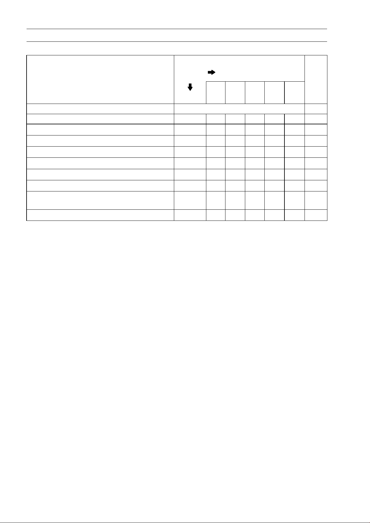
Periodic Replacement Parts
FREQUENCY Whichever
comes
first
* ODOMETER READING
× 1 000 km
(× 1 000 mile)
1 12 24 36 48
ITEM Every (0.6) (7.5) (15) (22.5) (30)
See
Page
Air cleaner element # - replace Every 18 000 km (11 250 mile) 2-51
Fuel hose - replace 5 years 2-51
Coolant - change 3 years
•
2-53
Radiator hose and O-ring - replace 3 years
•
2-56
Engine oil # - change year
• • • • •
2-57
Oilfilter-replace
year
• • • • •
2-57
Brake hose - replace 4 years
•
2-58
Brake fluid - change 2 years
• •
2-60
Rubber parts of master cylinder and caliper -
replace
4 years
•
2-61,
2-62
Spark plug - replace
• • • •
2-66
#: Service more frequently when operating in severe conditions; dusty, wet, muddy, high speed or
frequent starting/stopping.
*: For higher odometer readings, repeat at the frequency interval established here.

PERIODIC MAINTENANCE 2-7
Torque and Locking Agent
The following tables list the tightening torque for the major fasteners requiring use of a
non-permanent locking agent or silicone sealant etc.
Letters used in the “Remarks” column mean:
AL: Tighten the two clamp bolts alternately two times to ensure even tightening torque.
G: Apply grease.
L: Apply a non-permanent locking agent.
MO: Apply molybdenum disulfide oil solution.
(mixture of the engine oil and molybdenum disulfide grease in a weight ratio 10 : 1)
R: Replacement Parts
S: Follow the specified tightening sequence.
Si: Apply silicone grease (ex. PBC grease).
SS: Apply silicone sealant.
Torque
Fastener
N·m kgf·m ft·lb
Remarks
Fuel System (DFI)
Air Cleaner Duct Clamp Bolts
2.0 0.20 18 in·lb
Delivery PipeAssembly MountingScrews
3.43 0.35 30 in·lb
Throttle Body Assy
Holder Clamp Bolts
2.9 0.3 26 in·lb
Upper Air Cleaner Housing Screws 1.1 0.11 9.7 in·lb
Intake Air Temperature Sensor Screw 1.2 0.12 11 in·lb
Oxygen Sensor (Equipped Models) 44 4.5 32
Water Temperature Sensor 30 3.1 22
Exhaust Butterfly Valve Actuator Mounting
Screws
1.2 0.12 11 in·lb
Exhaust Butterfly Valve Actuator Pulley Bolt
5.0 0.51 44 in·lb
Fuel Pump Bolts 9.8 1.0 87 in·lb L
Cooling System
Coolant By-pass Fitting Bolt 8.8 0.90 78 in·lb L
Coolant Drain Bolt 11 1.1 97 in·lb
Radiator (Water) Hose Clamp Screws 2.9 0.30 26 in·lb
Thermostat Housing Bolts 5.9 0.60 52 in·lb L
Water Pipe Bolts 12 1.2 106 in·lb L
Water Pump Cov
er Bolts
11 1.1 97 in·lb
Water Pump Impeller Bolt 9.8 1.0 87 in·lb
Engine Top End
Air Suction Valve Cover Bolts 9.8 1.0 87 in·lb L
Camshaft Cap Bolts 12 1.2 106 in·lb S
Camshaft Chain Tensioner Cap Bolt 20 2.0 15
Camshaft Chain Tensioner Mounting Bolts 11 1.1 97 in·lb
Camshaft Sprocket Bolts 15 1.5 11 L
Cylinder Head Bolts (M10) (First) 20 2.0 15 S, MO
Cylinder Head Bolts (M10) (Final) 54 5.5 40 S, MO
Cylinder Head Bolts (M6)
12 1.2 106 in·lb
S
Cylinder Head Cover Bolts
9.8 1.0 87 in·lb
S
Front Cams
haft Chain Guide Bolt (Lower)
12 1.2 106 in·lb

2-8 PERIODIC MAINTENANCE
Torque and Locking Agent
Torque
Fastener
N·m kgf·m ft·lb
Remarks
Front Camshaft Chain Guide Bolt (Upper) 25 2.5 18
Plugs 19.6 2.0 14 L
Rear Camshaft Chain Guide Bolt 25 2.5 18
Spark Plugs 13 1.3 115 in·lb
Throttle Body Assy Holder Bolts 12 1.2 106 in·lb
Upper Camshaft Chain Guide Bolts 12 1.2 106 in·lb L
Exhaust Butterfly Valve Actuator Bolts 4.3 0.44 38 in·lb
Exhaust Butterfly Valve Actuator Pulley Bolt 5.0 0.51 44 in·lb
Muffler Body Mounting Bolts 34 3.5 25
Premuffler Chamber Mounting Bolt 34 3.5 25
Muffler Body Clamp Bolts 21 2.1 15
Clutch
Clutch Lever Assembly Clamp Bolts 7.8 0.80 69 in·lb S
Clutch Spring Bolts
8.8 0.90 78 in·lb
Clutch Cover Bolts
9.8 1.0 87 in·lb
Clutch Hub Nut
135 13.8 99.6 R
Engine Lubrication System
Engine Oil Drain Bolt 29 3.0 21
Lower Fairing Bracket Bolts 12 1.2 106 in·lb
Oil Cooler Bolts
12 1.2 106 in·lb
Oil Filler Plug
2.0 0.2 18 in·lb
Oil Filter
17 1.7 13
G, R
Oil Filter Pipe 25 2.5 18 L
Oil Pan Bolts 12 1.2 106 in·lb S
Oil Passage Plug 20 2.0 15 L
Oil Pressure Relief Valve 15 1.5 11 L
Oil Pressure Switch 15 1.5 11 SS
Radiator (Water) Hose Clamp Screws 2.9 0.30 26 in·lb
Engine Removal/Installation
Lower Adjusting Collar Locknut 49 5.0 36 S
Lower Adjusting Collar 9.8 1.0 87 in·lb S
Lower Engine Bracket Bolts 59 6.0 44
S
Lower Engine Mounting Nut 44 4.5 32
S
Middle Engine Bracket Bolts 25 2.5 18
L, S
Middle Engine Mounting Nut 44 4.5 32 S
Upper Adjusting Collar 5.0 0.51 44 in·lb S
Upper Adjusting Collar Locknut 49 5.0 36 S
Upper Engine Bracket Bolts 44 4.5 32 S
Upper Engine Mounting Bolt (L = 40) 44 4.5 32 S
Upper Engine Mounting Bolt (L = 65) 44 4.5 32 S
Crankshaft/Transmission
Balancer Shaft Clamp Bolt 9.8 1.0 87 in·lb
Balancer Shaft Clamp Lever Bolt 25 2.5 18 L

PERIODIC MAINTENANCE 2-9
Torque and Locking Agent
Torque
Fastener
N·m kgf·m ft·lb
Remarks
Breather Side Plate Bolt 5.9 0.60 52 in·lb
Connecting Rod Big End Nuts
see the text ← ←
MO
Breather Plate Bolts 9.8 1.0 87 in·lb L
Shift Drum Bearing Holder Bolts 12 1.2 106 in·lb L
Oil Passage Plugs 20 2.0 15 L
Oil Passage Plug 9.8 1.0 87 in·lb
Starter Motor Clutch Bolts 12 1.2 106 in·lb L
Crankcase Bolts (M7)
20 2.0 15
S
Crankcase Bolts (M9)
42 4.2 31
S, MO
Crankcase Bolts (M6
)
12 1.2 106 in·lb
S
Crankcase Bolts (M8) 27 2.8 20 S
Gear Positioning Lever Bolt 12 1.2 106 in·lb
Neutral Switch 15 1.5 11
Shift Drum Cam Bolt 12 1.2 106 in·lb L
Shift Pedal Mounting Bolt 25 2.5 18
Shift Shaft Return Spring Pin 39 4.0 29 L
Wheels/Tires
Front Axle 108 11.0 79.7
Front Axle Clamp Bolt 20 2.0 15
Rear Axle Nut 98 10 72
Final Drive
Chain Adjuster Clamp Bolts 64 6.5 47
Drive Chain Guide Bolts 9.8 1.0 87 in·lb
Engine Sprocket Nut 125 12.7 92.2 MO
Rear Sprocket Nults 59 6.0 44
Speed Sensor Mounting Bolt
6.9 0.70 61 in·lb L
Brakes
Bleed Valves 7.8 0.80 69 in·lb
Brake Hose Banjo Bolts 25 2.5 18
Brake Lever Pivot Bolt 1.0 0.10 8.8 in·lb Si
Brake Lever Pivot Bolt Locknut 5.9 0.60 52 in·lb
Front Brake Disc Mounting Bolts 27 2.8 20 L
Front Brake Light Switch Screw
1.2 0.12 11 in·lb
Front Brake Pad Pins 15 1.5 11
Front Brake Reservoir Bolt 7.8 0.80 69 in·lb L
Front Brake Reservoir Screw 1.2 0.12 11 in·lb L
Front Caliper Assembly Bolts 22 2.2 16
Front Caliper Mounting Bolts 34 3.5 25
Front Master Cylinder Bleed Valve 7.8 0.80 69 in·lb
Front Master Cylinder Clamp Bolts 11 1.1 97 in·lb S
Front Master Cylinder Reservoir Cap Screws 1.5 0.15 13 in·lb
Brake Pedal Bolt 8.8 0.90 78 in·lb L
Brake Pipe Joint Nuts (ABS Equipped Models) 18 1.8 13

2-10 PERIODIC MAINTENANCE
Torque and Locking Agent
Torque
Fastener
N·m kgf·m ft·lb
Remarks
Rear Brake Disc Mounting Bolts 27 2.8 20 L
Rear Caliper Mounting Bolts 25 2.5 18
Rear Master Cylinder Mounting Bolts 25 2.5 18
Rear Master Cylinder Push Rod Locknut 17 1.7 12
Suspension
Front Fork Bottom Allen Bolts 35 3.6 26
Front Fork Top Plugs 34 3.5 25
Lower Front Fork Clamp Bolts
25 2.5 18 AL
Piston Rod Nuts 20 2.0 15
Upper Front Fork Clamp Bolts 20 2.0 15
Rear Shock Absorber Nut (Lower) 34 3.5 25 R
Rear Shock Absorber Bolt (Upper) 34 3.5 25
Swingarm Pivot Shaft 20 2.0 15
Swingarm Pivot Adjusting Collar Locknut
98 10 72
Swingarm Pivot Shaft Nut
108 11.0 79.7
Tie-rod Nuts 34 3.5 25 R
Torque Link Nuts 34 3.5 25
Rocker Arm Nut 34 3.5 25 R
Steering
Handlebar Holder Bolts 25 2.5 18
Handlebar Holder Nuts 34 3.5 25 R
Left Switch Housing
Screws
3.5 0.36 31 in·lb
Right Switch Housing Screws 3.5 0.36 31 in·lb
Steering Stem Head Bolt 108 11.0 79.7
Steering Stem Nut 25 2.5 18
Frame
Center Fairing Assembly Screws
1.2 0.12 11 in·lb
Front Fender Asse
mbly Screws
1.2 0.12 11 in·lb
Front Fender Mounting Bolts 3.9 0.40 35 in·lb
Rear View Mirror (Lower Hexagonal Area) 30 3.1 22
Rear View Mirror (Upper Hexagonal Area) 18 1.8 13
Front Footpeg Bracket Bolts 25 2.5 18
Rear Footpeg Bracket Bolts 25 2.5 18
Rear Frame Bolts 25 2.5 18 L
Rear Frame Joint Bracket Bolts 44 4.5 32
Sidestand Bolt 44 4.5 32 S
Sidestand Locknut 29 3.0 21 R, S
Sidestand Bracket Bolts 49 5.0 36 L
Sidestand Switch Bolt 8.8 0.90 78 in·lb L
Electrical System
Front Brake Light Switch Screw 1.2 0.12 11 in·lb
Front Turn Signal Light Mounting Screws 1.2 0.12 11 in·lb
Licence Plate Light Mounting Screws 1.2 0.12 11 in·lb
PERIODIC MAINTENANCE 2-11
Torque and Locking Agent
Torque
Fastener
N·m kgf·m ft·lb
Remarks
Meter Unit Mounting Screws 1.2 0.12 11 in·lb
Oxygen Sensor (Equipped Models)
44 4.5 32
Switch Housing Screws
3.5 0.36 31 in·lb
Alternator Cover Bolt
s (Engine No. ∼
ZRT00DE013356)
9.8 1.0 87 in·lb
Alternator Cover Bolts 12 1.2 106 in·lb
Alternator Lead Hold
ing Plate Bolt
12 1.2 106 in·lb L
Alternator Rotor Bolt 155 15.8 114
Brush Holder Screw 3.8 0.39 34 in·lb
Crankshaft Sensor Bolts 5.9 0.60 52 in·lb
Crankshaft Sensor Cover Bolts (Engine No. ∼
ZRT00DE013356)
9.8 1.0 87 in·lb
Crankshaft Sensor Cover Bolts 12 1.2 106 in·lb
Oil Pressure Switch 15 1.5 11 SS
Oil Pressure Switch Terminal Bolt 2.0 0.20 18 in·lb G
Spark Plugs 13 1.3 115 in·lb
Starter Motor Through Bolts 4.9 0.50 43 in·lb
Starter Motor Cable Terminal Nut 5.9 0.60 52 in·lb
Starter Motor Mounting Bolts 9.8 1.0 87 in·lb
Starter Motor Terminal Locknut
11 1.1 97 in·lb
Stator Coil Bolts
12 1.2 106 in·lb L
Timing Rotor Bolt 39 4.0 29
Water Temperature Sensor 30 3.1 22
Engine Ground Cable Terminal Bolt 9.8 1.0 87 in·lb
Neutral Switch 15 1.5 11
Sidestand Switch Bolt
8.8 0.90 78 in·lb L
Speed Sensor Mounting Bolt
6.9 0.70 61 in·lb L
The table below, relating tightening torque to thread diameter, lists the basic torque for the bolts and
nuts. Use this table for only the bolts and nuts which do not require a specific torque value. All of the
values are for use with dry solvent-cleaned threads.
Basic Torque for General Fasteners
Torque
Threads Diameter
(mm)
N·m kgf·m ft·lb
5 3.4 ∼ 4.9 0.35 ∼ 0.50 30 ∼ 43 in·lb
6 5.9 ∼ 7.8 0.60 ∼ 0.80 52 ∼ 69 in·lb
8 14
∼ 19
1.
4 ∼ 1.9
10
.0 ∼ 13.5
10 25 ∼ 34 2.6 ∼ 3.5 19.0 ∼ 25
12 44 ∼ 61 4.5 ∼ 6.2 33 ∼ 45
14 73 ∼ 98 7.4 ∼ 10.0 54 ∼ 72
16 115 ∼ 155 11.5 ∼ 16.0 83 ∼ 115
18 165 ∼ 225 17.0 ∼ 23.0 125 ∼ 165
20 225 ∼ 325 23.0 ∼ 33.0 165 ∼ 240

2-12 PERIODIC MAINTENANCE
Specifications
Item Standard Service Limit
Fuel System (DFI)
Throttle Grip Free Play 2 ∼ 3 mm (0.08 ∼ 0.12 in.) –––
Idle Speed 1 100 ±50 r/min (rpm) –––
Bypass Screws (Turn Out) 2 1/2 (for reference) –––
Throttle Body Vacuum 40.7 ±1.3 kPa (305 ±10 mmHg) at idle
speed
–––
Air Cleaner Element Viscous paper element –––
Cooling System
Coolant:
Type (Recommended) Permanent type of antifreeze
–––
Color Green –––
Mixed Ratio Soft water 50%, Coolant 50% –––
Freezing Point –35°C (–31°F) –––
Total Amount 2.9 L (3.1 US qt) –––
Engine Top End
Valve Clearance:
Exhaust 0.22 ∼ 0.31 mm (0.0087 ∼ 0.0122 in.) –––
Intake 0.15 ∼ 0.24 mm (0.0059 ∼ 0.0094 in.) –––
Clutch
Clutch Lever Free Play 2 ∼ 3 mm (0.08 ∼ 0.12 in.) –––
Engine Lubrication System
Engine Oil:
Type API SG, SH, SJ, SL or SM with JASO
MA, MA1 or MA2
–––
Viscosity SAE 10W-40 –––
Capacity 3.2 L (3.4 US qt) (when filter is not
removed)
–––
3.8 L (4.0 US qt) (when filter is removed) –––
4.0 L (4.2 US qt) (when engine is
completely dry)
–––
Wheels/Tires
Tread Depth:
Front:
ZR1000D
4.0 mm (0.16 in.)
ZR1000E
3.8 mm (0.15 in.)
1 mm (0.04 in.),
(AT, CH, DE)
1.6 mm (0.06 in.)
Rear:
ZR1000D
5.5 mm (0.22 in.)
ZR1000E
5.4 mm (0.21 in.)
Up to 130 km/h (80 mph):
2 mm (0.08 in.),
Over 130 km/h (80 mph):
3 mm (0.12 in.)
Air Pressure (when Cold):
Front Up to 180 kg (397 lb) load:
250 kPa (2.5 kgf/cm², 36 psi)
–––
Rear
Up to 180 kg (397 lb) load:
290 kPa (2.9 kgf/cm², 42 psi)
–––

PERIODIC MAINTENANCE 2-13
Specifications
Item Standard Service Limit
Final Drive
Drive Chain Slack 20 ∼ 30 mm (0.8 ∼ 1.2 in.)
–––
Drive Chain Wear (20-link
Length)
317.5 ∼ 318.2 mm (12.50 ∼ 12.53 in.) 319 mm (12.56 in.)
Standard Chain:
Make ENUMA –––
Type EK525ZX –––
Link 112 Links –––
Brakes
Brake Fluid:
Grade DOT4 –––
Brake Pad Lining
Thickness:
Front
4.0 mm (0.16 in.) 1 mm (0.04 in.)
Rear 5.0 mm (0.20 in.) 1 mm (0.04 in.)
Brake Light Timing:
Front
Pulled ON
–––
Rear
ON after about 10 mm (0.39 in.) of
pedal travel
–––
Electrical System
Spark Plug:
Type NGK CR9EIA-9 –––
2-14 PERIODIC MAINTENANCE
Special Tools
Inside Circlip Pliers:
57001-143
Steering Stem Nut Wrench:
57001-1100
Jack:
57001-1238
Oil Filter Wrench:
57001-1249
Attachment Jack:
57001-1252
Spark Plug Wrench, Hex 16:
57001-1262
Vacuum Gauge:
57001-1369
Throttle Sensor Setting Adapter:
57001-1538
Fuel Hose:
57001-1607
Jack Attachment:
57001-1608
PERIODIC MAINTENANCE 2-15
Periodic Maintenance Procedures
Fuel System (DFI)
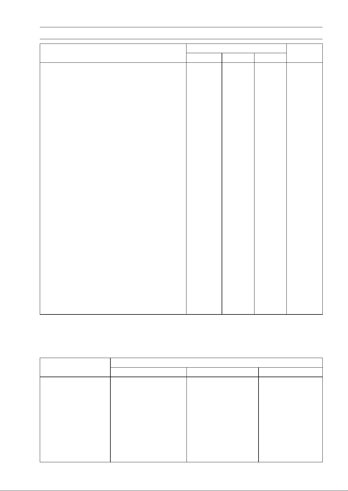
Throttle Control System Inspection
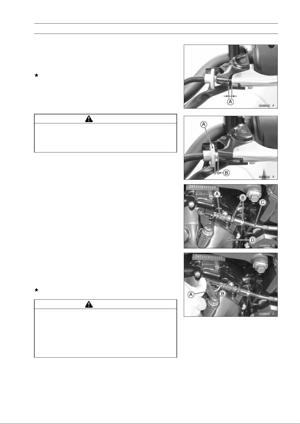
•
Check that the throttle grip [A] moves smoothly from full
open to close, and the throttle closes quickly and com-
pletely by the return spring in all steering positions.
If the throttle grip does not return properly, check the throt-
tle cable routing, grip free play, and cable damage. Then
lubricate the throttle cable.
•
Check the throttle grip free play [B].
Throttle Grip Free Play
Standard: 2
∼ 3 mm (0.08 ∼ 0.12 in.)
If the free play is incorrect, adjust the throttle cable as
follows.
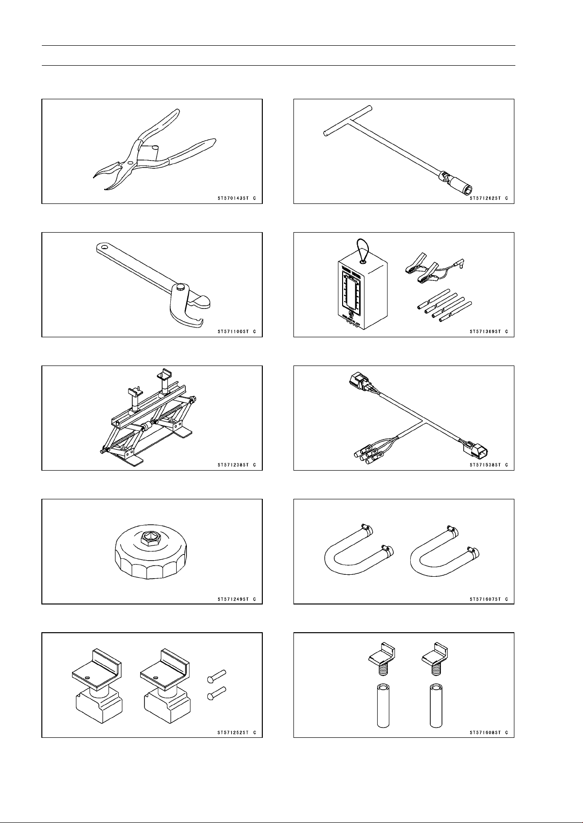
•
Loosen the locknuts [A] [B].
•
Screw both throttle cable adjusters [C] [D] to give the
throttle grip plenty of play.
•
Turn the decelerator cable adjuster [C] until 2 ∼ 3mm
(0.08 ∼ 0.12 in.) of throttle grip play is obtained.
•
Tighten the locknut [A].
•
Turn the accelerator cable adjuster [D] until 2 ∼ 3mm
(0.08 ∼ 0.12 in.) of throttle grip play is obtained.
•
Tighten the locknut [B].
If the free play can not be adjusted with the adjusters,
replace the cable.
Engine Vacuum Synchronization Inspection
NOTE
○
These procedures are explained on the assumption that
the intake and exhaust systems of the engine are in
good condition.
•
Situate the motorcycle so that it is vertical.
•
Remove the air cleaner housing (see Air Cleaner Housing
Removal in the Fuel System (DFI) chapter).
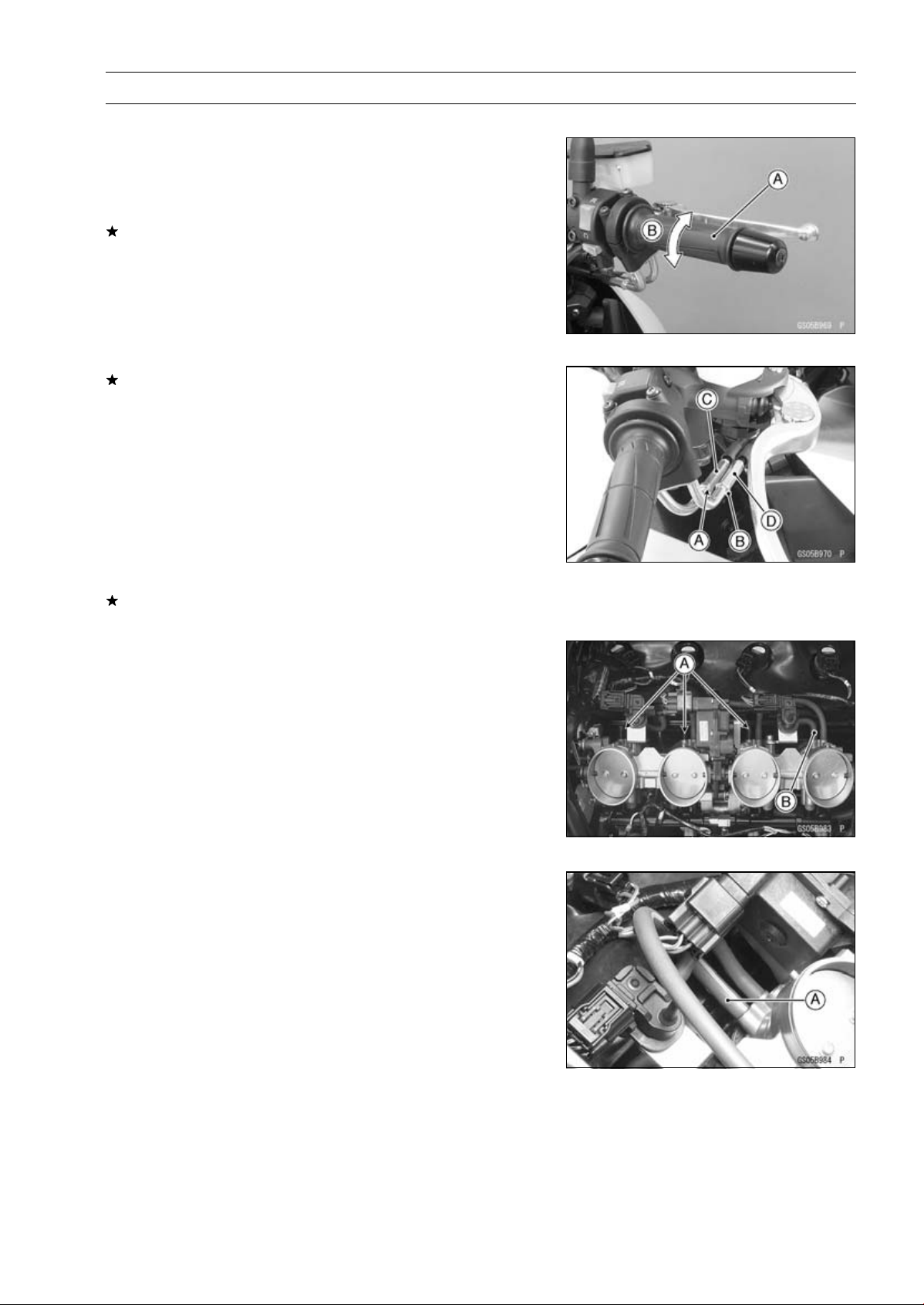
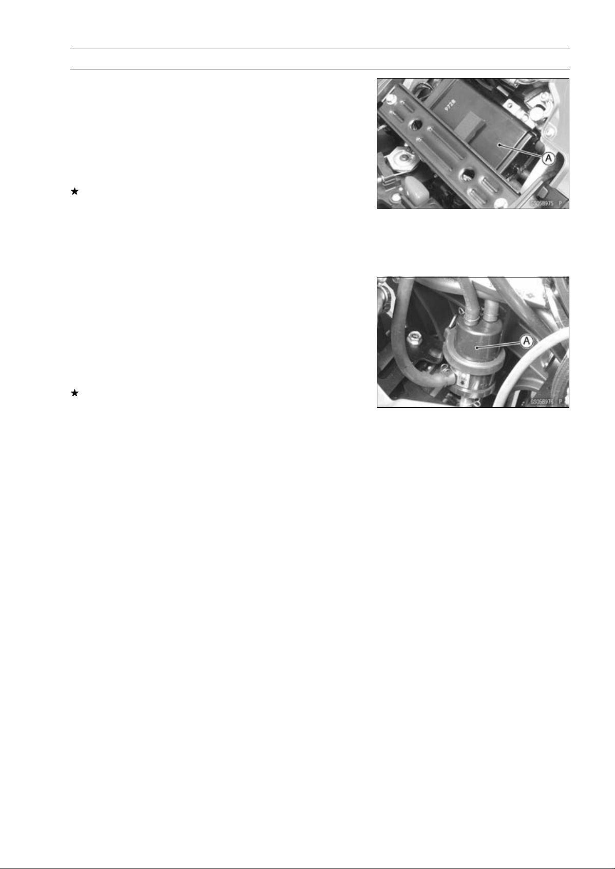
•
Pull off the rubber caps [A] and vacuum hose [B] from the
fittings of each throttle body.
•
For the CAL, SEA-B1 and TH Models, pull off the vacuum
hose [A].
2-16 PERIODIC MAINTENANCE
Periodic Maintenance Procedures
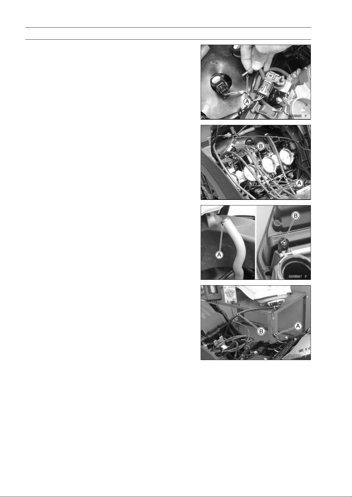
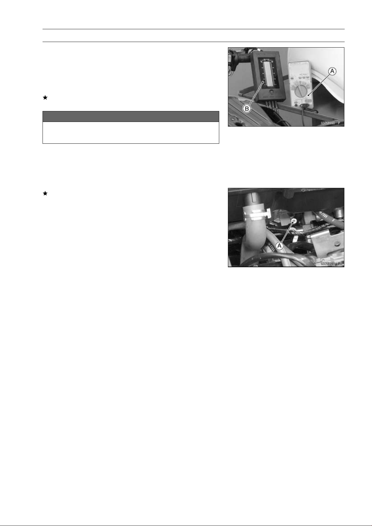
•
Plug the vacuum hose end [A].
•
Connect a vacuum gauge (special tool) and hoses [A] to
the fittings on the throttle body.
Special Tool - Vacuum Gauge: 57001-1369
•
Connect a highly accurate tachometer [B] to one of the
stick coil primary leads.
•
Plug the air switching valve hose end [A] and air cleaner
housing fitting [B].
•
Install the air cleaner housing (see Air Cleaner Housing
Installation in the Fuel System (DFI) chapter).
•
Remove the fuel hose (see Fuel Tank Removal in the Fuel
System (DFI) chapter).
•
Connect the following parts temporary.
Fuel Pump Lead Connector [A]
Fuel Hose [B]
Special Tool - Fuel Hose: 57001-1607
PERIODIC MAINTENANCE 2-17
Periodic Maintenance Procedures
•
Start the engine and warm it up thoroughly.
•
Check the idle speed, using a highly accurate tachometer
[A].
Idle Speed
Standard: 1 100 ±50 r/min (rpm)
If the idle speed is out of the specified range, adjust it with
the adjusting screw (see Idle Speed Adjustment).
NOTICE
Do not measure the idle speed by the tachometer of
the meter unit.
•
While idling the engine, inspect the throttle body vacuum,
using the vacuum gauge [B].
Throttle Body Vacuum
Standard: 40.7 ±1.3 kPa (305 ±10 mmHg) at idle speed
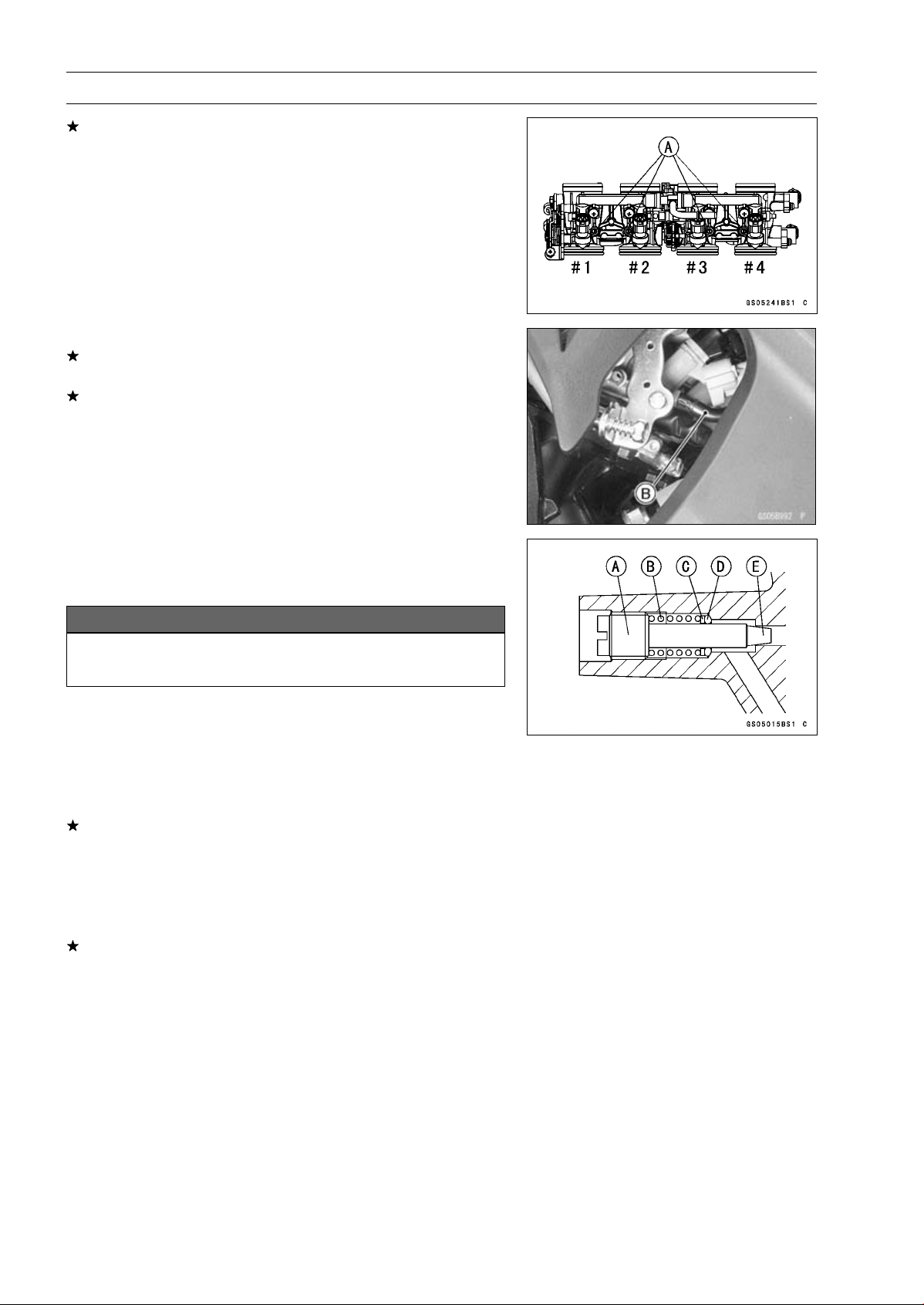
If any vacuum is not within specifications, first synchro-
nize the balance of the left (#1, #2 throttle valves) and
right (#3, #4 throttle valves) assemblies.
Example:
#1: 260 mmHg
#2: 300 mmHg
#3: 250 mmHg
#4: 280 mmHg
•
With the engine at the correct idle speed, equalize higher
vacuum of #1 or #2 (for example 300 mmHg) to higher
vacuum of #3 or #4 (for example 280 mmHg) by turning
the center adjusting screw [A].
NOTE
○
After adjustment, the final vacuum measurement be-
tween the highest throttle valves may not be 290 mmHg
(for example). The goal is to have the highest two vac-
uums between the left (#1 and #2) and right (#3 and #4)
banks be the same.
•
Open and close the throttle after each measurement, and
adjust the idle speed as necessary.
•
Once the throttle valves have been synchronized, inspect
output voltage of the main throttle sensor to ensure proper
operation (procedure is explained at the end of this sec-
tion).
2-18 PERIODIC MAINTENANCE
Periodic Maintenance Procedures
If any one vacuum measurement is out of the specified
range after left (#1, #2) and right (#2, #3) synchronization,
adjust the bypass screws [A].
Special Tool - Pilot Screw Adjuster, A [B]: 57001-1239
•
Adjust the lower vacuum between #1 and #2 to the higher
vacuum of #1 and #2.
•
Adjust the lower vacuum between #3 and #4 to the higher
vacuum of #3 and #4.
•
Open and close the throttle valves after each measure-
ment, and adjust the idle speed as necessary.
•
Check the vacuums as before.
If all vacuums are within the specification range, finish the
engine vacuum synchronization.
If any vacuum can not be adjusted within the specification,
remove the bypass screws #1 ∼ #4 and clean them.
•
Turn in the bypass screw [A] with counting the number of
turns until it seals fully but not tightly. Record the number
of turns.
NOTICE
Do not over tighten them. They could be damaged,
requiring replacement.
•
Remove:
Bypass Screw
Spring [B]
Washer [C]
O-ring [D]
•
Check the bypass screw and its hole for carbon deposits.
If any carbons accumulate, wipe the carbons off from the
bypass screw and the hole, using a cotton pad penetrated
with a high flash-point solvent.
•
Replace the O-ring with a new one.
•
Check the tapered portion [E] of the bypass screw for
wear or damage.
If the bypass screw is worn or damaged, replace it.
•
Turn in the bypass screw until it seats fully but not tightly.
PERIODIC MAINTENANCE 2-19
Periodic Maintenance Procedures
•
Back out the same number of turns counted when first
turned in. This is to set the screw to its original position.
NOTE
○
A throttle body has different “turns out” of the bypass
screw for each individual unit. On setting the bypass
screw, use the “turns out” determined during disassem-
bly.
•
Repeat the same procedure for other bypass screws.
•
Repeat the synchronization.
If the vacuums are correct, check the output voltage of
the main throttle sensor (see Main Throttle Sensor Output
Voltage Inspection in the Fuel System (DFI) chapter).
Special Tool - Throttle Sensor Setting Adapter: 57001
-1538
Main Throttle Sensor Output Voltage
Connections to Adapter:
Digital Meter (+) W (sensor BL/W) lead
Digital Meter (–) BK (sensor BR/BK) lead
Standard: DC 0.985
∼ 1.015 V at idle throttle opening
If the output voltage is out of the standard, check the in-
put voltage of the main throttle sensor (see Main Throttle
Sensor Input Voltage Inspection in the Fuel System (DFI)
chapter).
•
Remove the vacuum gauge hoses and install the rubber
caps on the original position.
•
For the CAL, SEA-B1 and TH Models, install the vacuum
hoses.
○
Route the vacuum hoses according to Cable, Wire, and
Hose Routing section in the Appendix chapter. Refer to
the diagram of the evaporative emission control system
in the Fuel System (DFI) chapter too.
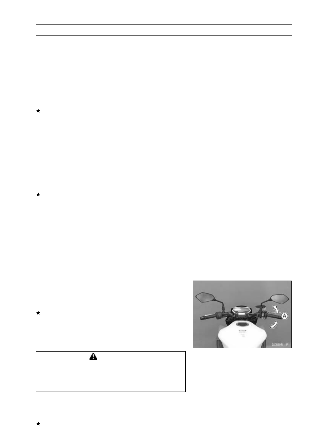
Idle Speed Inspection
•
Start the engine and warm it up thoroughly.
•
With the engine idling, turn the handlebar to both sides
[A].
If handlebar movement changes the idle speed, the
throttle cables may be improperly adjusted or incorrectly
routed or damaged. Be sure to correct any of these
conditions before riding (see Throttle Control System
Inspection and Cable, Wire, and Hose Routing section in
the Appendix chapter).
WARNING
Operation with improperly adjusted, incorrectly
routed or damaged cables could result in an unsafe
riding condition. Follow the service manual to be
make sure to correct any of these conditions.
•
Check the idle speed.
Idle Speed
Standard: 1 100 ±50 r/min (rpm)
If the idle speed is out of the specified range, adjust it.
2-20 PERIODIC MAINTENANCE
Periodic Maintenance Procedures
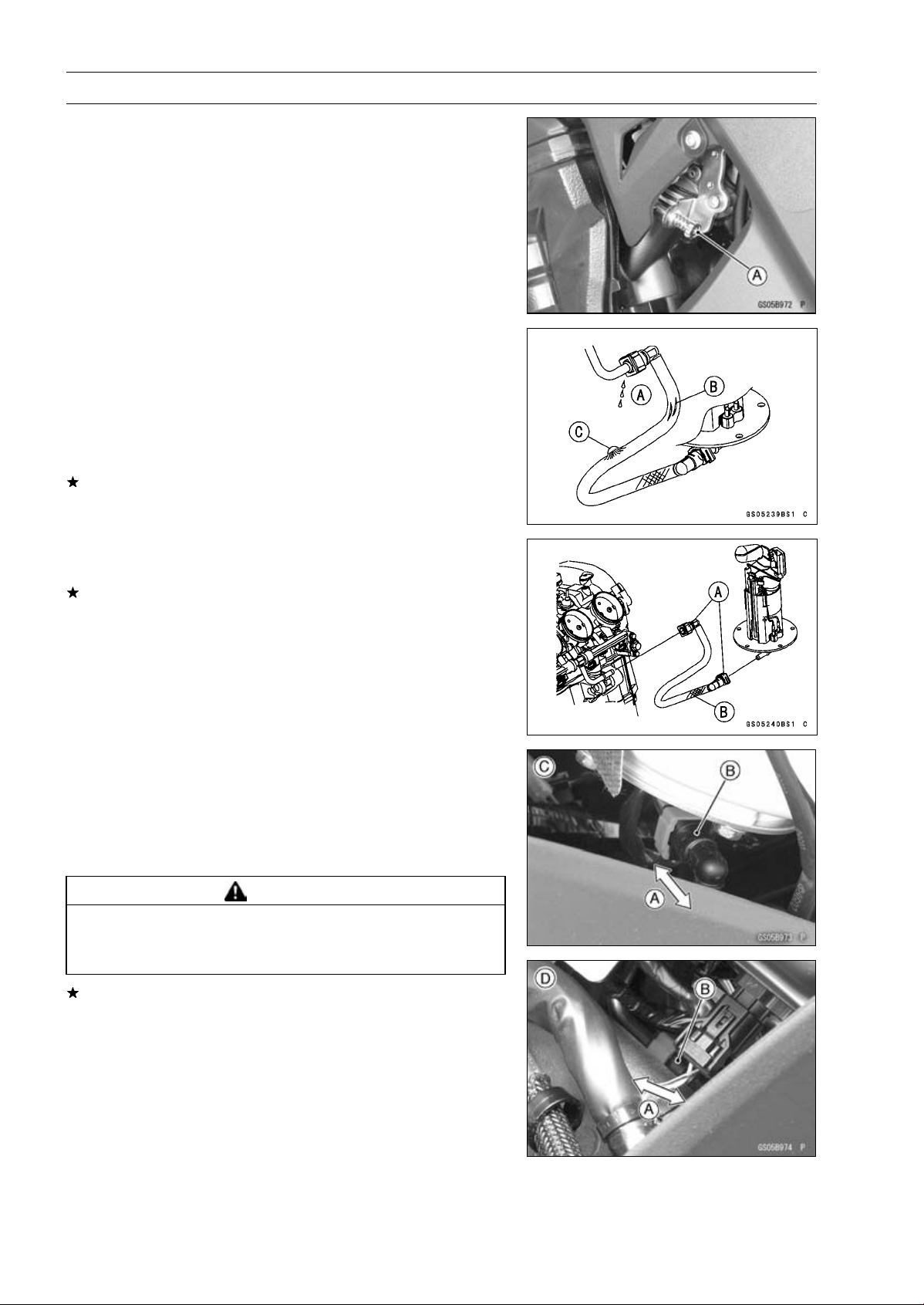
Idle Speed Adjustment
•
Start the engine and warm it up thoroughly.
•
Turn the adjusting screw [A] until the idle speed is correct.
○
Open and close the throttle a few times to make sure that
the idle speed is within the specified range. Readjust if
necessary.
Fuel Hose Inspection (fuel leak, damage,
installation condition)
○
If the motorcycle is not properly handled, the high pres-
sure inside the fuel line can cause fuel to leak [A] or the
hose to burst. Support the fuel tank with a suitable bar
(see Fuel Tank Removal in the Fuel System (DFI) chap-
ter) and check the fuel hoses.
Replace the hose if any fraying, cracks [B] or bulges [C]
are noticed.
•
Check that the hoses are routed according to Cable, Wire,
and Hose Routing section in the Appendix chapter.
Replace the hose if it has been sharply bent or kinked.
Hose Joints [A]
Fuel Hose [B]
•
Check that the hose joints are securely connected.
○
Push and pull [A] the hose joint [B] back and forth more
than two times, and make sure it is locked and does not
come off.
Fuel Pump Side [C]
Throttle Body Assy Side [D]
WARNING
Leaking fuel can cause a fire or explosion resulting
in serious burns. Make sure the hose joint is in-
stalled correctly on the delivery pipe.
If it comes off, reinstall the hose joint.
PERIODIC MAINTENANCE 2-21
Periodic Maintenance Procedures
Evaporative Emission Control System (CAL,
SEA-B1 and TH Models) Inspection
•
Inspect the canister as follows.
○
Remove the front seat (see Front Seat Removal in the
Frame chapter).
○
Remove the canister [A], and disconnect the hoses from
the canister.
○
Visually inspect the canister for cracks or other damage.
If the canister has any cracks or bad damage, replace it
with a new one.
NOTE
○
The canister is designed to work well through the motor-
cycle’s life without any maintenance if it is used under
normal conditions.
•
Check the liquid/vapor separator as follows.
○
Lift up the fuel tank front side, and support the fuel tank
with the suitable bar (Fuel Tank Removal in the Fuel Sys-
tem (DFI) chapter).
○
Disconnect the hoses from the separator, and remove the
separator [A] from the motorcycle right side.
○
Visually inspect the separator for cracks and other dam-
age.
If the separator has any cracks or damage, replace it with
a new one.
○
To prevent the gasoline from flowing into or out of the
canister, hold the separator perpendicular to the ground.
•
Check the hoses of the evaporative emission control sys-
tem as follows.
○
Check that the hoses are securely connected and clips
are in position.
○
Replace any kinked, deteriorated or damaged hoses.
○
Route the hoses according to Cable, Wire, and Hose
Routing section in the Appendix chapter. Refer to the di-
agram of the evaporative emission control system in the
Fuel System (DFI) chapter too.
○
When installing the hoses, avoid sharp bending, kinking,
flattening or twisting, and route the hoses with a minimum
of bending so that the emission flow will not be obstructed.
2-22 PERIODIC MAINTENANCE
Periodic Maintenance Procedures
Cooling System
Coolant Level Inspection
NOTE
○
Check the level when the engine is cold (room or ambi-
ent temperature).
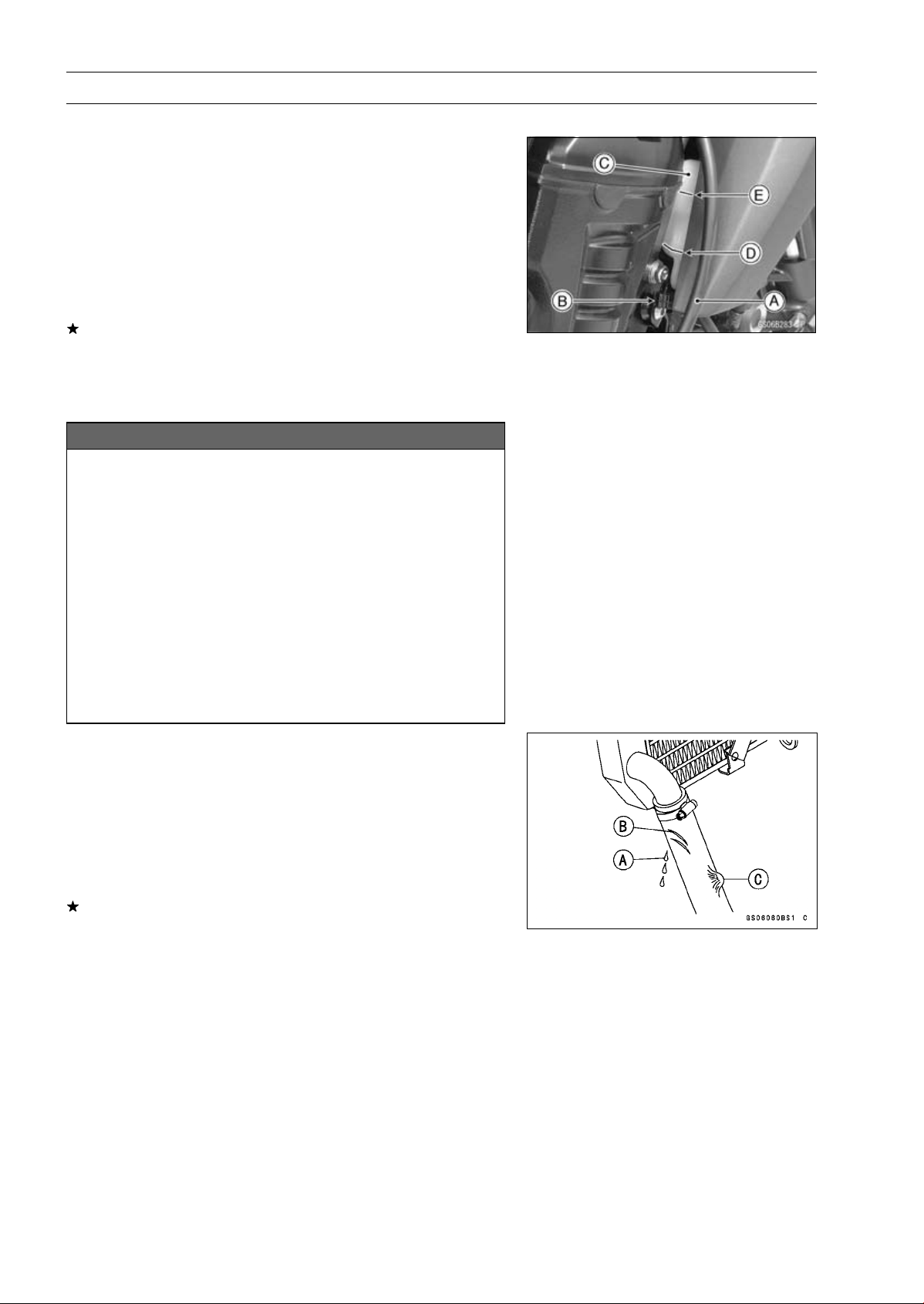
•
Clear the clutch cable [A] from the clamp [B].
•
Check the coolant level in the reserve tank [C] with the
motorcycle held perpendicular (Do not use the side-
stand.).
If the coolant level is lower than the “L” level line [D], un-
screw the reserve tank cap and add coolant to the “F”
level line [E].
“L”: low
“F”: full
NOTICE
For refilling, add the specified mixture of coolant
and soft water. Adding water alone dilutes the
coolant and degrades its anticorrosion properties.
The diluted coolant can attack the aluminum en-
gine parts. In an emergency, soft water alone can
be added. But the diluted coolant must be returned
to the correct mixture ratio within a few days.
If coolant must be added often or the reservoir tank
has run completely dry, there is probably leakage in
the cooling system. Check the system for leaks.
Coolant ruins painted surfaces. Immediately wash
away any coolant that spills on the frame, engine,
wheels or other painted parts.
Radiator Hose and Pipe Inspection (coolant leak,
damage, installation condition)
○
The high pressure inside the radiator hose can cause
coolant to leak [A] or the hose to burst if the line is not
properly maintained.
•
Visually inspect the hoses for signs of deterioration.
Squeeze the hoses. A hose should not be hard and
brittle, nor should it be soft or swollen.
Replace the hose if any fraying, cracks [B] or bulges [C]
are noticed.
•
Check that the hoses are securely connected and clamps
are tightened correctly.
Torque - Radiator (Water) Hose Clamp Screws: 2.9 N·m
(0.30 kgf·m, 26 in·lb)
PERIODIC MAINTENANCE 2-23
Periodic Maintenance Procedures
Engine Top End
Valve Clearance Inspection
NOTE
○
Valve clearance must be checked and adjusted when
the engine is cold (room temperature).
•
Remove:
Crankshaft Sensor Cover (see Crankshaft Sensor Re-
moval in the Electrical System chapter)
Cylinder Head Cover (see Cylinder Head Cover Re-
moval in the Engine Top End chapter)
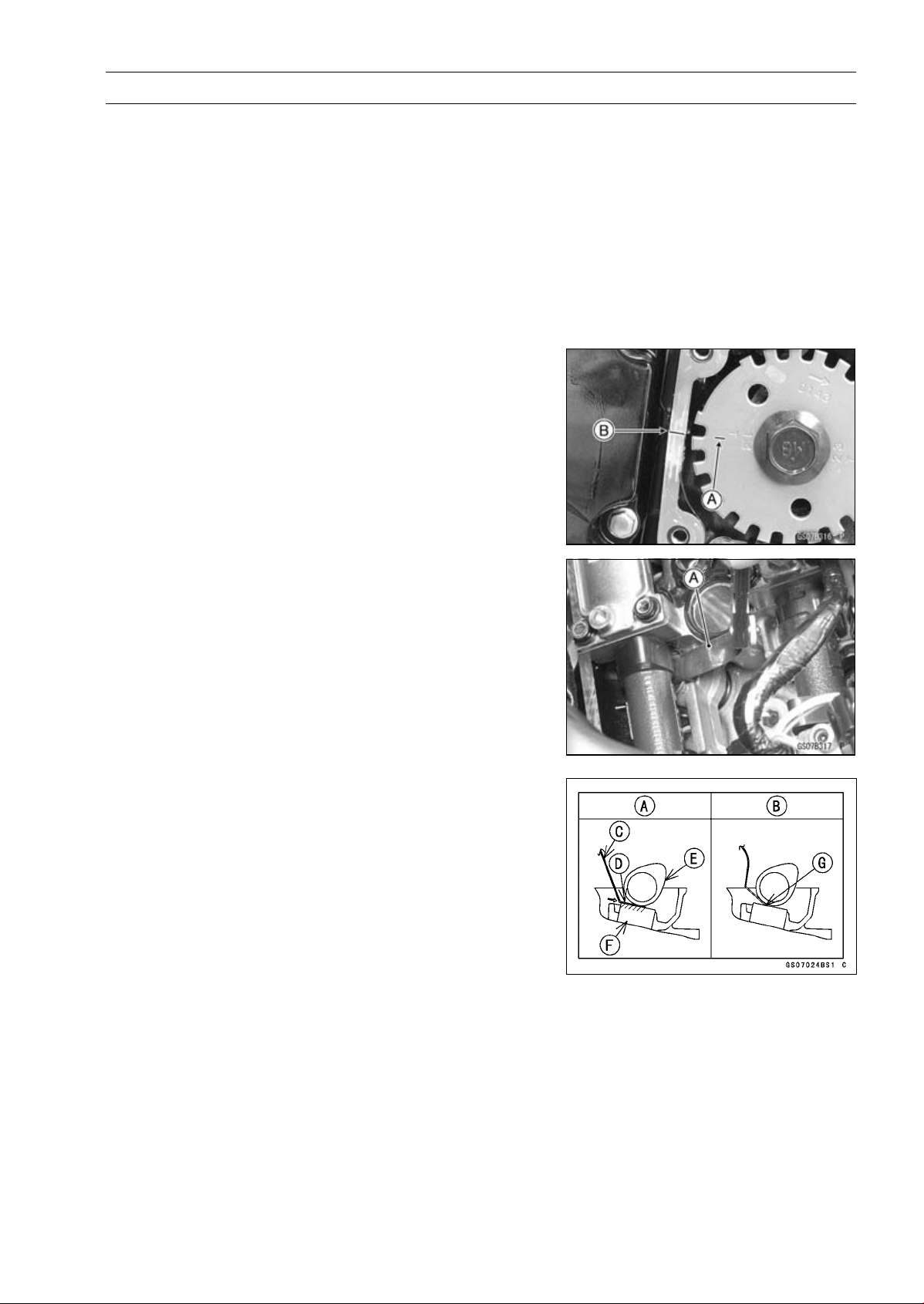
•
Turn the crankshaft, align the #1, 4 mark on the timing
rotor with the crankcase timing mark.
TDC Mark [A] for #1, 4 Pistons
Timing Mark [B] (Crankcase Halves Mating Surface)
•
Using the thickness gauge [A], measure the valve clear-
ance between the cam and the valve lifter.
Valve Clearance
Standard:
Exhaust
0.22
∼ 0.31 mm (0.0087 ∼ 0.0122 in.)
Intake
0.15
∼ 0.24 mm (0.0059 ∼ 0.0094 in.)
NOTE
○
Thickness gauge is horizontally inserted on the valve
lifter.
Appropriateness [A]
Inadequacy [B]
Thickness Gauge [C]
Horizontally Inserts [D]
Cam [E]
Valve Lifter [F]
Hits the Valve Lifter Ahead [G]
2-24 PERIODIC MAINTENANCE
Periodic Maintenance Procedures
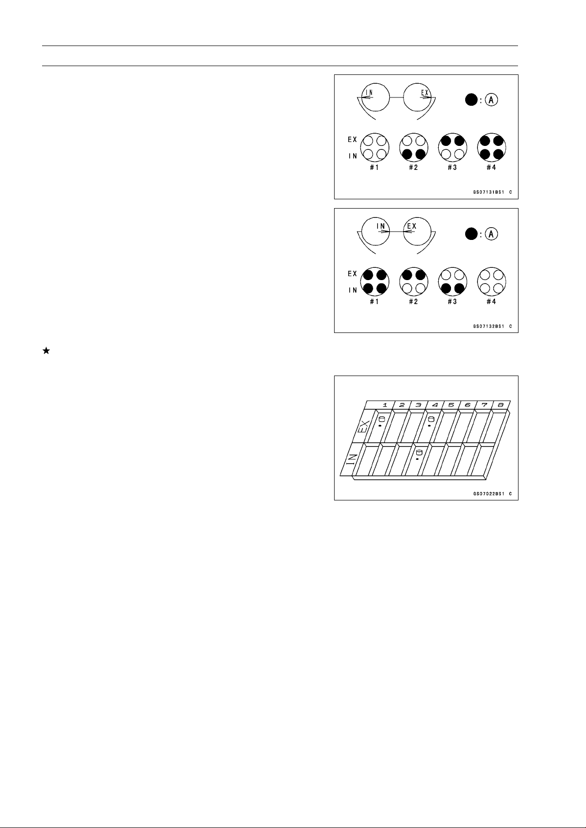
○
When positioning #4 piston TDC at the end of the
compression stroke:
Intake Valve Clearance of #2 and #4 Cylinders
Exhaust Valve Clearance of #3 and #4 Cylinders
Measuring Valve [A]
○
When positioning #1 piston TDC at the end of the
compression stroke:
Intake Valve Clearance of #1 and #3 Cylinders
Exhaust Valve Clearance of #1 and #2 Cylinders
Measuring Valve [A]
If the valve clearance is not within the specified range,
first record the clearance, and then adjust it.
Valve Clearance Adjustment
•
To change the valve clearance, remove the camshaft
chain tensioner, camshafts and valve lifters. Replace the
shim with one of a different thickness.
NOTE
○
Mark and record the locations of the valve lifters and
shims so that they can be reinstalled in their original
positions.
PERIODIC MAINTENANCE 2-25
Periodic Maintenance Procedures
○
Besides the standard shims in the valve clearance adjust-
ment charts, the following shims may be installed at the
factory. Although they are not available as spare parts,
they can be used to adjust valve clearance.
Adjustment Shims
Thickness
3.225 mm
3.275 mm
3.325 mm
2.675 mm
2.725 mm
2.775 mm
2.825 mm
2.875 mm
2.925 mm
2.975 mm
3.025 mm
3.075 mm
3.125 mm
3.175 mm
•
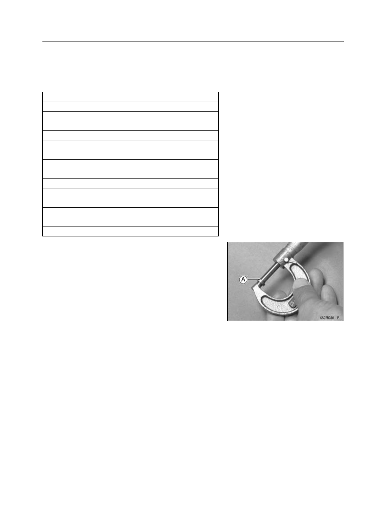
Clean the shim to remove any dust or oil.
•
Measure the thickness of the removed shim [A].
2-26 PERIODIC MAINTENANCE
Periodic Maintenance Procedures
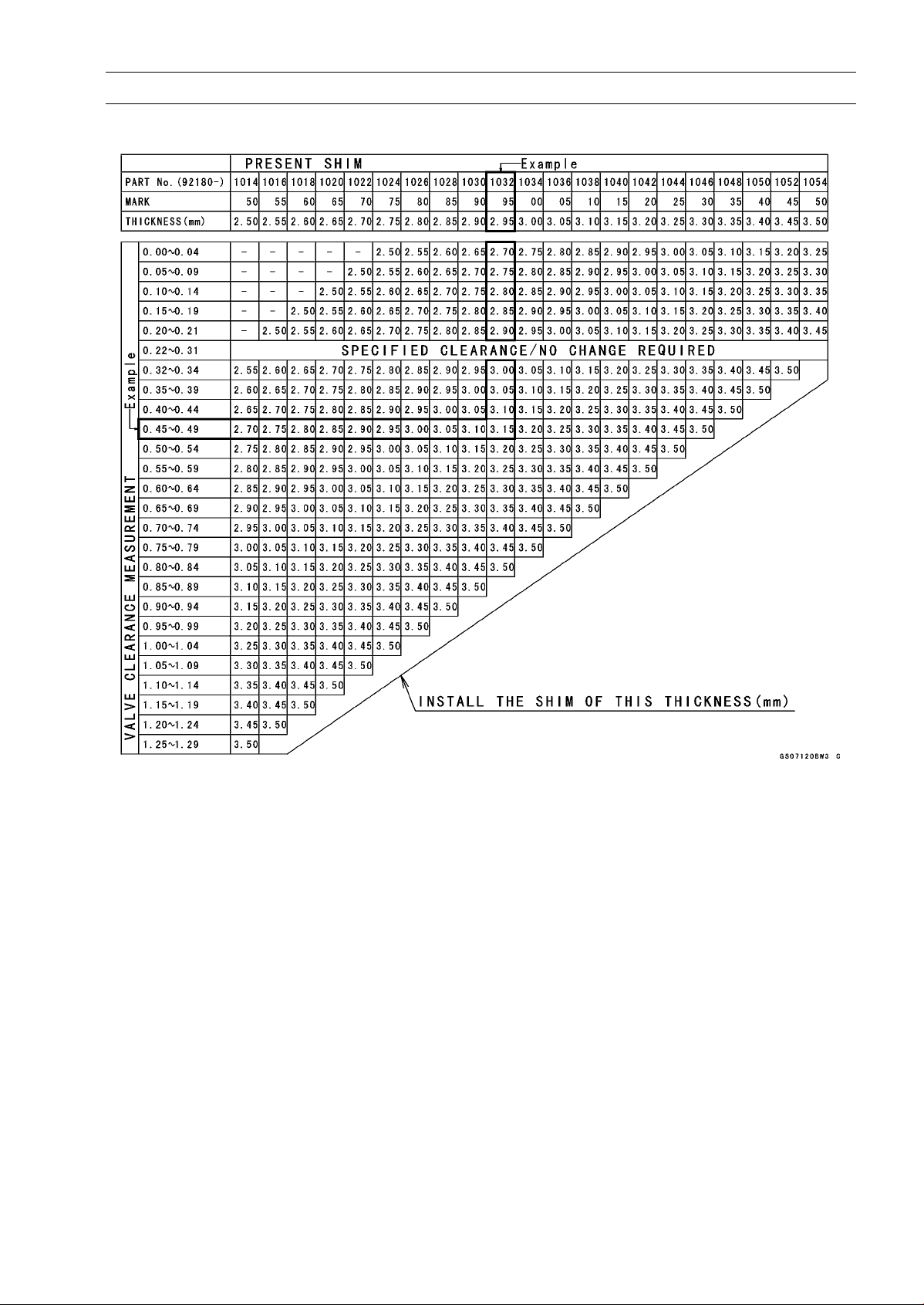
VALVE CLEARANCE ADJUSTMENT CHART INTAKE VALVE
1. Measure the clearance (when engine is cold).
2. Check present shim size.
3. Match clearance in vertical column with present shim size in horizontal column.
4. Install the shim specified where the lines intersect. This shim will give the proper clearance.
Example: Present shim is 2.95 mm
Measured clearance is 0.45 mm
Replace 2.95 mm shim with 3.20 mm shim.
5. Remeasure the valve clearance and readjust if necessary.
PERIODIC MAINTENANCE 2-27
Periodic Maintenance Procedures
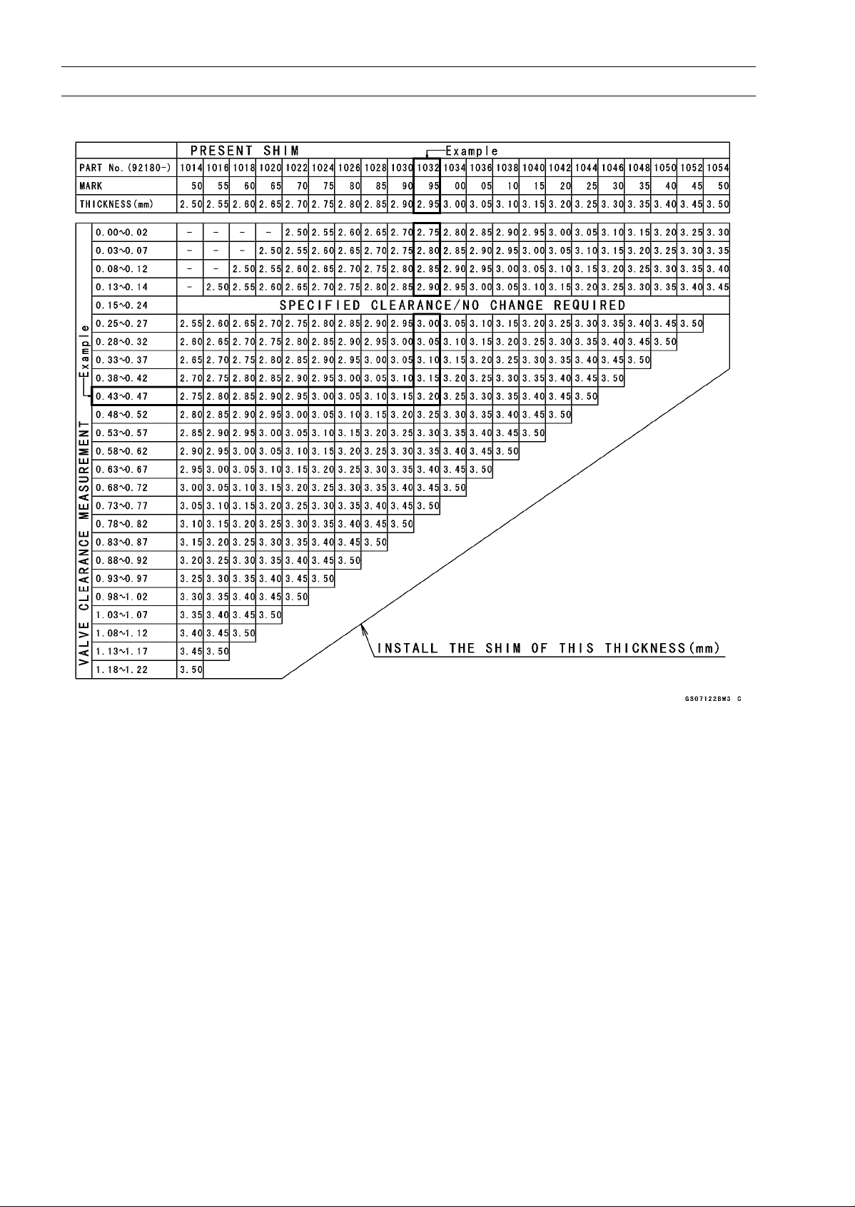
VALVE CLEARANCE ADJUSTMENT CHART EXHAUST VALVE
1. Measure the clearance (when engine is cold).
2. Check present shim size.
3. Match clearance in vertical column with present shim size in horizontal column.
4. Install the shim specified where the lines intersect. This shim will give the proper clearance.
Example: Present shim is 2.95 mm.
Measured clearance is 0.47 mm.
Replace 2.95 mm shim with 3.15 mm shim.
5. Remeasure the valve clearance and readjust if necessary.
2-28 PERIODIC MAINTENANCE
Periodic Maintenance Procedures
NOTICE
Be sure to remeasure the clearance after selecting
a shim according to the table. If the clearance is out
of the specified range, use the additional shim.
○
If there is no valve clearance, use a shim that is a few
sizes smaller, and remeasure the valve clearance.
•
When installing the shim, face the marked side toward the
valve lifter.
NOTICE
Do not put shim stock under the shim. This may
cause the shim to pop out at high rpm, causing ex-
tensive engine damage.
Do not grind the shim. This may cause it to fracture,
causing extensive engine damage.
•
Apply engine oil to the valve lifter surface and install the
lifter.
•
Install the camshaft (see Camshaft Installation in the En-
gine Top End chapter).
•
Recheck the valve clearance and readjust if necessary.
•
Install the removed parts (see appropriate chapters).
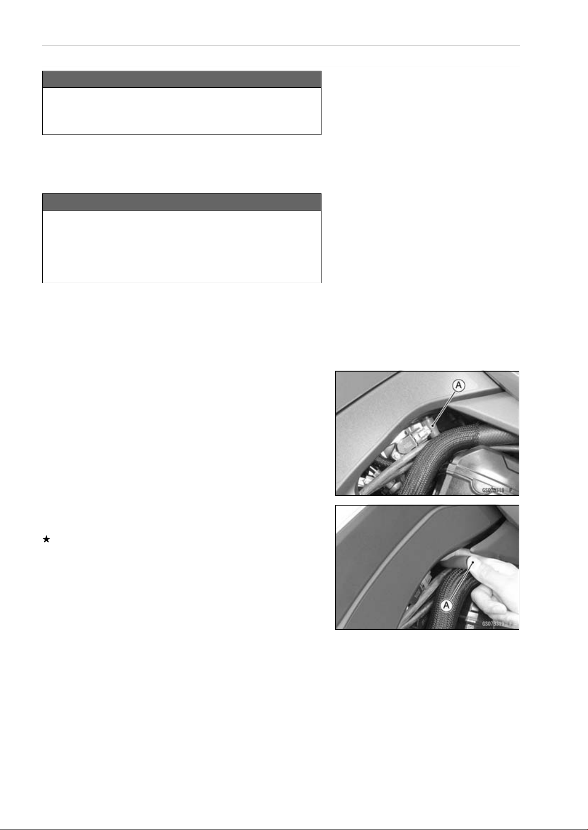
Air Suction System Damage Inspection
•
Pull the air switching valve hose [A] out of the air cleaner
housing.
•
Start the engine and run it at idle speed.
•
Plug [A] the air switching valve hose end with your finger
and feel vacuum pulsing in the hose.
If there is no vacuum pulsation, check the hose line for
leak. If there is no leak, check the air switching valve
(see Air Switching Valve Unit Test in the Electrical Sys-
tem chapter) or air suction valve (see Air Suction Valve
Inspection in the Engine Top End chapter).
PERIODIC MAINTENANCE 2-29
Periodic Maintenance Procedures
Clutch
Clutch Operation Inspection
•
Pull the clutch lever just enough to take up the free play
[A].
•
Measure the gap between the lever and the lever holder.
If the gap is too wide, the clutch may not release fully. If
the gap is too narrow, the clutch may not engage fully. In
either case, adjust it.
Clutch Lever Free Play
Standard: 2
∼ 3 mm (0.08 ∼ 0.12 in.)
WARNING
The engine and exhaust system get extremely hot
during normal operation and can cause serious
burns. Never touch the engine or exhaust pipe
during clutch adjustment.
•
Turn the adjuster [A] so that 5 ∼ 6 mm (0.20 ∼ 0.24 in.) [B]
of threads are visible.
•
Slide the dust cover [A] at the clutch cable lower end out
of place.
•
Loosen both adjusting nuts [B] at the clutch cover as far
as they will go.
•
Pull the clutch outer cable [C] tight and tighten the adjust-
ing nuts against the clutch cover [D].
•
Slip the dust cover back onto place.
•
Turn the adjuster at the clutch lever until the free play is
correct.
•
Push the release lever [A] toward the front of the motor-
cycle until it becomes hard to turn.
○
At this time, the release lever should have the proper an-
gle shown.
60° [B]
If the angle is wrong, check the clutch and release parts
for wear.
WARNING
Too much cable play can prevent clutch disengage-
ment and cause an accident resulting in serious in-
jury or death. When adjusting the clutch or replac-
ing the cable, be sure the upper end of the clutch
outer cable is fully seated in its fitting, or it could
slip into place later, creating enough cable play to
prevent clutch disengagement.
•
After the adjustment, start the engine and check that the
clutch does not slip and that it releases properly.
2-30 PERIODIC MAINTENANCE
Periodic Maintenance Procedures
Wheels/Tires
Air Pressure Inspection
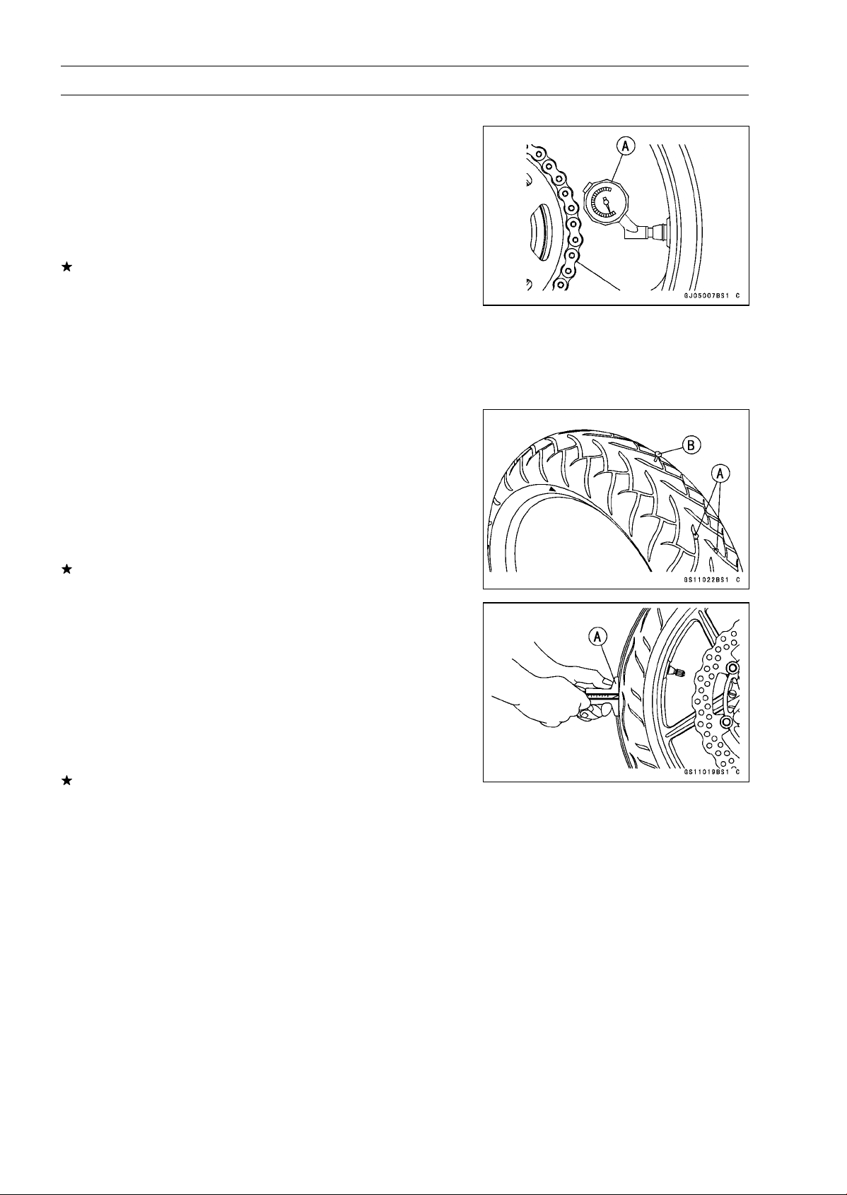
•
Remove the air valve cap.
•
Measure the tire air pressure with an air pressure gauge
[A] when the tires are cold (that is, when the motorcycle
has not been ridden more than a mile during the past 3
hours).
•
Install the air valve cap.
Adjust the tire air pressure according to the specifications
if necessary.
Air Pressure (when Cold)
Front:
Upto180kg(397lb)
250 kPa (2.5 kgf/cm², 36 psi)
Rear:
Upto180kg(397lb)
290 kPa (2.9 kgf/cm², 42 psi)
Wheel/Tire Damage Inspection
•
Remove any imbedded stones [A] or other foreign parti-
cles [B] from tread.
•
Visually inspect the tire for cracks and cuts, and replace
the tire if necessary. Swelling or high spots indicate inter-
nal damage, requiring tire replacement.
•
Visually inspect the wheel for cracks, cuts and dents dam-
age.
If any damage is found, replace the wheel if necessary.
Tire Tread Wear Inspection
As the tire tread wears down, the tire becomes more sus-
ceptible to puncture and failure. An accepted estimate is
that 90% of all tire failures occur during the last 10% of tread
life (90% worn). So it is false economy and unsafe to use
the tires until they are bald.
•
Measure the tread depth at the center of the tread with a
depth gauge [A]. Since the tire may wear unevenly, take
measurement at several places.
If any measurement is less than the service limit, replace
the tire (see Tire Removal/Installation in the Wheels/Tires
chapter).
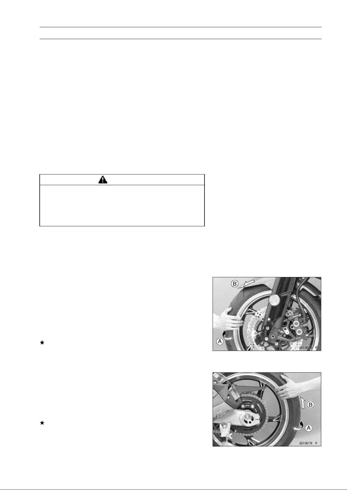
PERIODIC MAINTENANCE 2-31
Periodic Maintenance Procedures
Tread Depth
Standard:
Front:
ZR1000D 4.0 mm (0.16 in.)
ZR1000E 3.8 mm (0.15 in.)
Rear:
ZR1000D
5.5 mm (0.22 in.)
ZR1000E
5.4 mm (0.22 in.)
Service Limit:
Front
1 mm (0.04 in.)
(AT, CH, DE) 1.6 mm (0.06 in.)
Rear
2 mm (0.08 in.)
Up to 130 km/h (80 mph)
3 mm (0.12 in.)
Over 130 km/h (80 mph)
WARNING
Some replacement tires may adversely affect han-
dling and cause an accident resulting in serious in-
jury or death. To ensure proper handling and sta-
bility, use only the recommended standard tires for
replacement, inflated to the standard pressure.
NOTE
○
Most countries may have their own regulations a mini-
mum tire tread depth: be sure to follow them.
○
Check and balance the wheel when a tire is replaced
with a new one.
Wheel Bearing Damage Inspection
•
Raise the front wheel off the ground with the jack (see
Front Wheel Removal in the Wheels/Tires chapter).
•
Turn the handlebar all the way to the right or left.
•
Inspect the roughness of the front wheel bearing by push-
ing and pulling [A] the wheel.
•
Spin [B] the front wheel lightly, and check for smoothly
turn, roughness, binding or noise.
If roughness, binding or noise is found, remove the front
wheel and inspect the wheel bearing (see Front Wheel
Removal, Hub Bearing Inspection in the Wheels/Tires
chapter).
•
Raise the rear wheel off the ground with the stand (see
Rear Wheel Removal in the Wheels/Tires chapter).
•
Inspect the roughness of the rear wheel bearing by push-
ing and pulling [A] the wheel.
•
Spin [B] the rear wheel lightly, and check for smoothly
turn, roughness, binding or noise.
If roughness, binding or noise is found, remove the rear
wheel and inspect the wheel bearing (see Rear Wheel Re-
moval, Hub Bearing Inspection in the Wheels/Tires chap-
ter) and coupling (see Coupling Bearing Inspection in the
Final Drive chapter).
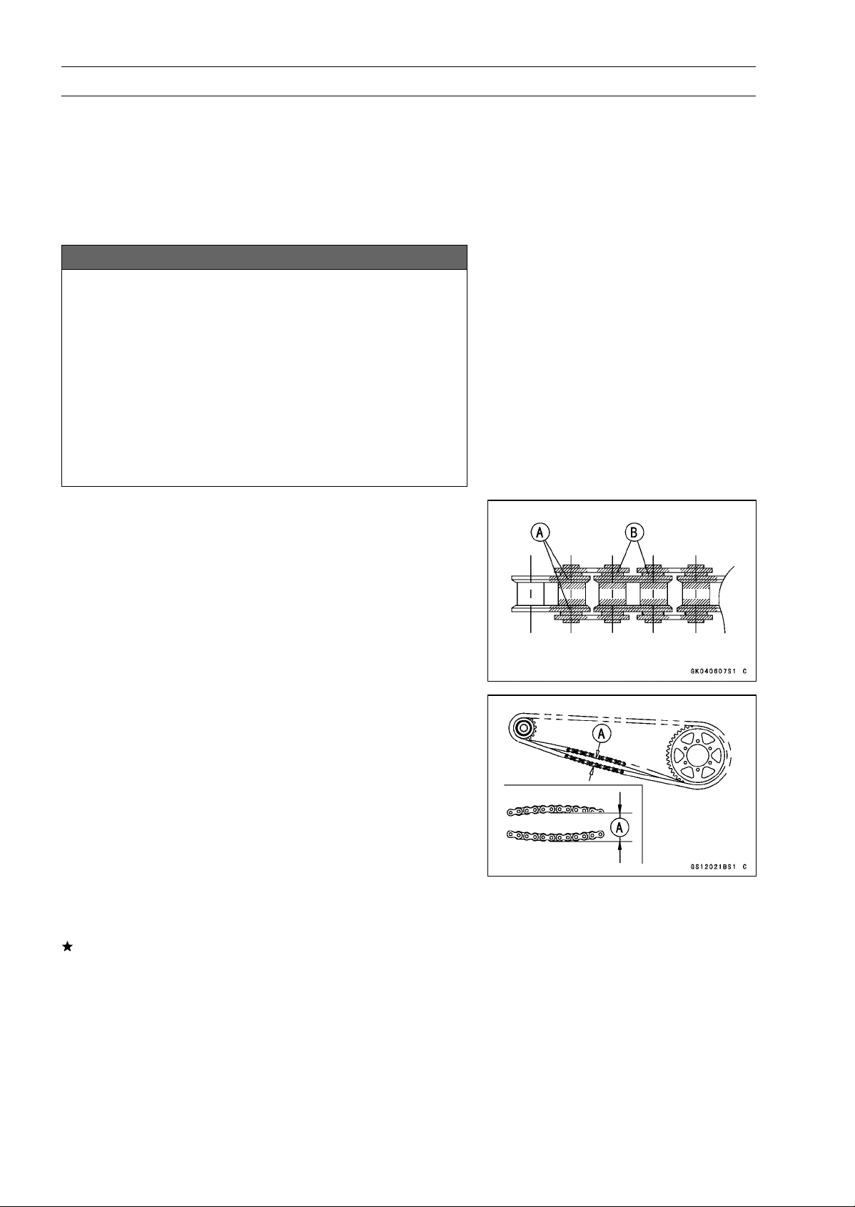
2-32 PERIODIC MAINTENANCE
Periodic Maintenance Procedures
Final Drive
Drive Chain Lubrication Condition Inspection
•
If a special lubricant is not available, a heavy oil such as
SAE 90 is preferred to a lighter oil because it will stay on
the chain longer and provide better lubrication.
•
If the chain appears especially dirty, clean it before lubri-
cation.
NOTICE
The O-rings between the side plates seal in the lu-
bricant between the pin and the bushing. To avoid
damaging the O-rings and resultant loss of lubri-
cant, observe the following rules.
Use only kerosene or diesel oil for cleaning of the O
-ring of the drive chain. Any other cleaning solution
such as gasoline or trichloroethylene will cause de-
terioration and swelling of the O-ring. Immediately
blow the chain dry with compressed air after clean-
ing. Complete cleaning and drying the chain within
10 minutes.
•
Apply oil to the sides of the rollers so that oil will penetrate
to the rollers and bushings. Apply the oil to the O-rings so
that the O-rings will be coated with oil.
•
Wipe off any excess oil.
Oil Applied Areas [A]
O-rings [B]
Drive Chain Slack Inspection
NOTE
○
Check the slack with the motorcycle setting on its side-
stand.
○
Clean the chain if it is dirty, and lubricate it if it appears
dry.
•
Check the wheel alignment (see Wheel Alignment Inspec-
tion).
•
Rotate the rear wheel to find the position where the chain
is tightest.
•
Measure the vertical movement (chain slack) [A] midway
between the sprockets.
If the chain slack exceeds the standard, adjust it.
Chain Slack
Standard: 20
∼ 30 mm (0.8 ∼ 1.2 in.)
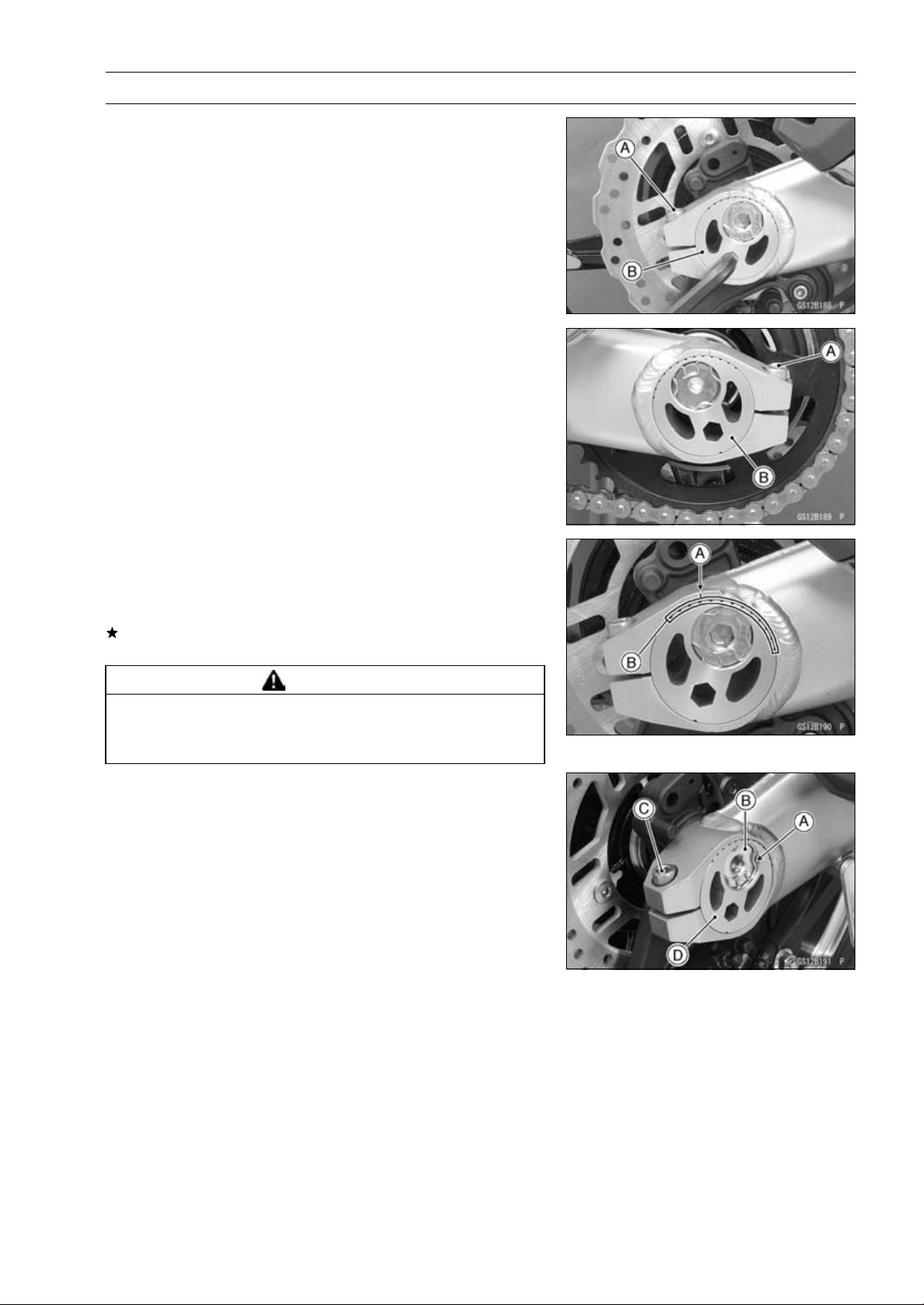
PERIODIC MAINTENANCE 2-33
Periodic Maintenance Procedures
Drive Chain Slack Adjustment
•
Loosen the left and right chain adjuster clamp bolts [A].
•
Using an Allen wrench, turn the adjusters [B] forward or
rearward until the drive chain has the correct amount of
chain slack.
•
Tighten:
Torque - Chain Adjuster Clamp Bolts: 64 N·m (6.5 kgf·m, 47
ft·lb)
Wheel Alignment Inspection
•
Check that the left and right notches [A] the swingarm
should point to the same marks or positions [B] on the
left and right adjuster.
If they do not, adjust the chain slack (see Drive Chain
Slack Adjustment) and align the wheel alignment.
WARNING
Misalignment of the wheel will result in abnormal
wear and may result in an unsafe riding condition.
Be sure the wheel is properly aligned.
Wheel Alignment Adjustment
•
Remove the right retaining ring [A] from the axle shaft.
•
Loosen the axle nut [B].
•
Loosen the right chain adjuster clamp bolt [C], and turn
the right chain adjuster [D] so that the left and right
notches on the swingarm may point to the same marks
or positions on the left and right adjusters.
•
Tighten:
Torque - Chain Adjuster Clamp Bolt: 64 N·m (6.5 kgf·m, 47
ft·lb)
Rear Axle Nut: 98 N·m (10 kgf·m, 72 ft·lb)
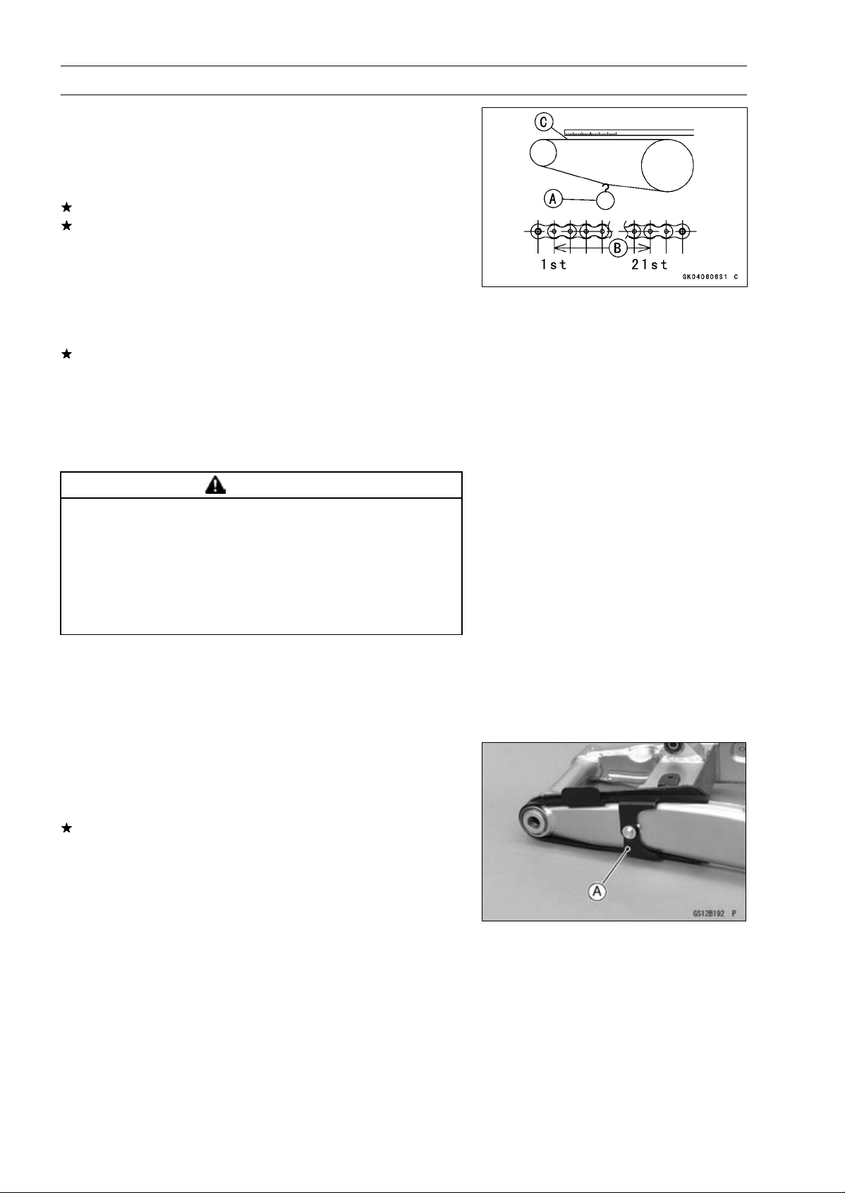
2-34 PERIODIC MAINTENANCE
Periodic Maintenance Procedures
Drive Chain Wear Inspection
•
Remove the chain cover (see Drive Chain Removal in the
Final Drive chapter).
•
Rotate the rear wheel to inspect the drive chain for dam-
aged rollers, and loose pins and links.
If there is any irregularity, replace the drive chain.
Lubricate the drive chain if it appears dry.
•
Stretch the chain taut by hanging a 98 N (10 kg, 20 lb)
weight [A] on the chain.
•
Measure the length of 20 links [B] on the straight part [C] of
the chain from the pin center of the 1st pin to the pin center
of the 21st pin. Since the chain may wear unevenly, take
measurements at several places.
If any measurements exceed the service limit, replace the
chain. Also, replace the front and rear sprockets when the
drive chain is replaced.
Drive Chain 20-link Length
Standard: 317.5
∼ 318.2 mm (12.50 ∼ 12.53 in.)
Service Limit: 319 mm (12.56 in.)
WARNING
A chain that breaks or jumps off the sprockets
could snag on the engine sprocket or lock the
rear wheel, severely damaging the motorcycle and
causing it to go out of control. Inspect the chain for
damage and proper adjustment before each ride.
If chain wear exceeds the service limit, replace it
with the standard chain.
Standard Chain
Make: ENUMA
Type: EK525ZX
Link: 112 Links
Chain Guide Wear Inspection
•
Remove the swingarm (see Swingarm Removal in the
Suspension chapter).
•
Visually inspect the chain guide [A].
Replace the chain guide if it shows any signs of abnormal
wear or damage.
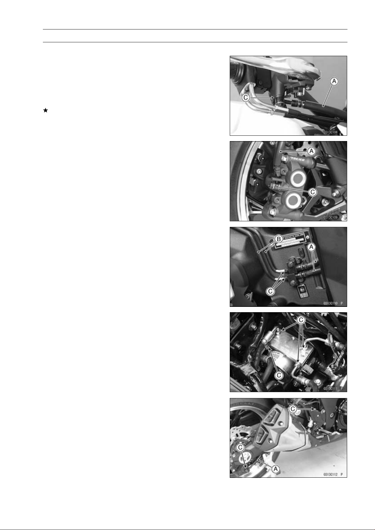
PERIODIC MAINTENANCE 2-35
Periodic Maintenance Procedures
Brakes
Brake Fluid Leak (Brake Hose and Pipe) Inspection
•
For ABS equipped models, remove the fuel tank (see Fuel
Tank Removal in the Fuel System (DFI) chapter).
•
Apply the brake lever or pedal and inspect the brake fluid
leak from the brake hoses [A], pipes (ABS equipped mod-
els) [B] and fittings [C].
If the brake fluid leaked from any position, inspect or re-
place the problem part.
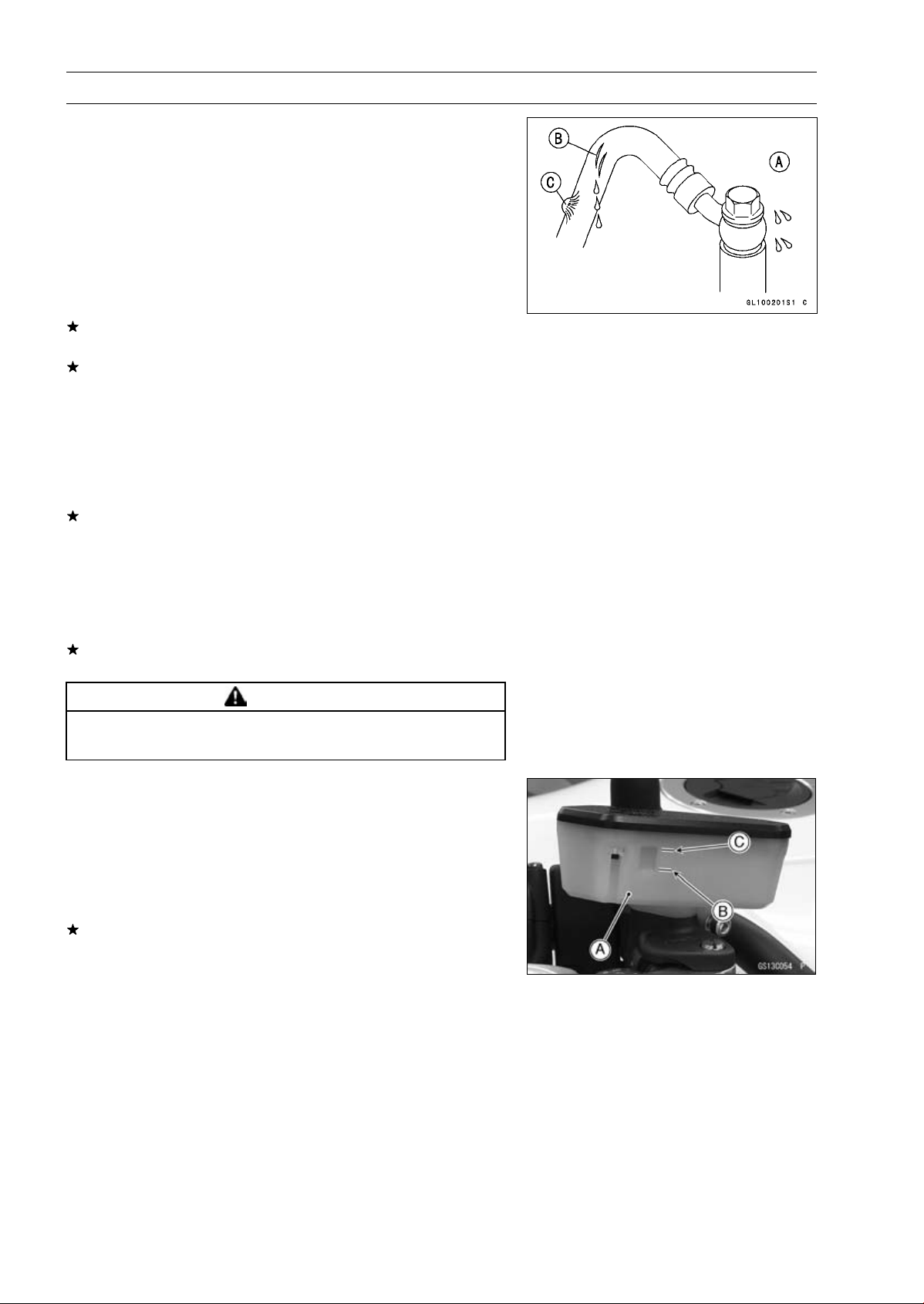
2-36 PERIODIC MAINTENANCE
Periodic Maintenance Procedures
Brake Hose and Pipe Damage and Installation
Condition Inspection
•
For ABS equipped models, remove the fuel tank (see Fuel
Tank Removal in the Fuel System (DFI) chapter).
•
Inspect the brake hoses and fittings for deterioration,
cracks and signs of leakage.
○
The high pressure inside the brake line can cause fluid to
leak [A] or the hose, pipe (ABS equipped models) to burst
if the line is not properly maintained. Bend and twist the
rubber hose while examining it.
Replace the hose and pipe (ABS equipped models) if any
crack [B], bulge [C] or leakage is noticed.
Tighten any brake hose banjo bolts and brake pipe joint
nuts.
Torque - Brake Hose Banjo Bolts: 25 N·m (2.5 kgf·m, 18
ft·lb)
Brake Pipe Joint Nuts: 18 N·m (1.8 kgf·m, 13 ft·lb)
(ABS Equipped Models)
•
Inspect the brake hose routing.
If any brake hose routing is incorrect, route the brake hose
according to Cable, Wire, and Hose Routing section in the
Appendix chapter.
Brake Operation Inspection
•
Inspect the operation of the front and rear brake by run-
ning the vehicle on the dry road.
If the brake operation is insufficiency, inspect the brake
system.
WARNING
When test riding the vehicle, be aware of surround-
ing traffic for your safety.
Brake Fluid Level Inspection
•
Check that the brake fluid level in the front brake reservoir
[A] is above the lower level line [B].
NOTE
○
Hold the reservoir horizontal by turning the handlebar
when checking brake fluid level.
If the fluid level is lower than the lower level line, fill the
reservoir to the upper level line [C].
•
Tighten:
Torque - Front Master Cylinder Reservoir Cap Screws: 1.5
N·m (0.15 kgf·m, 13 in·lb)
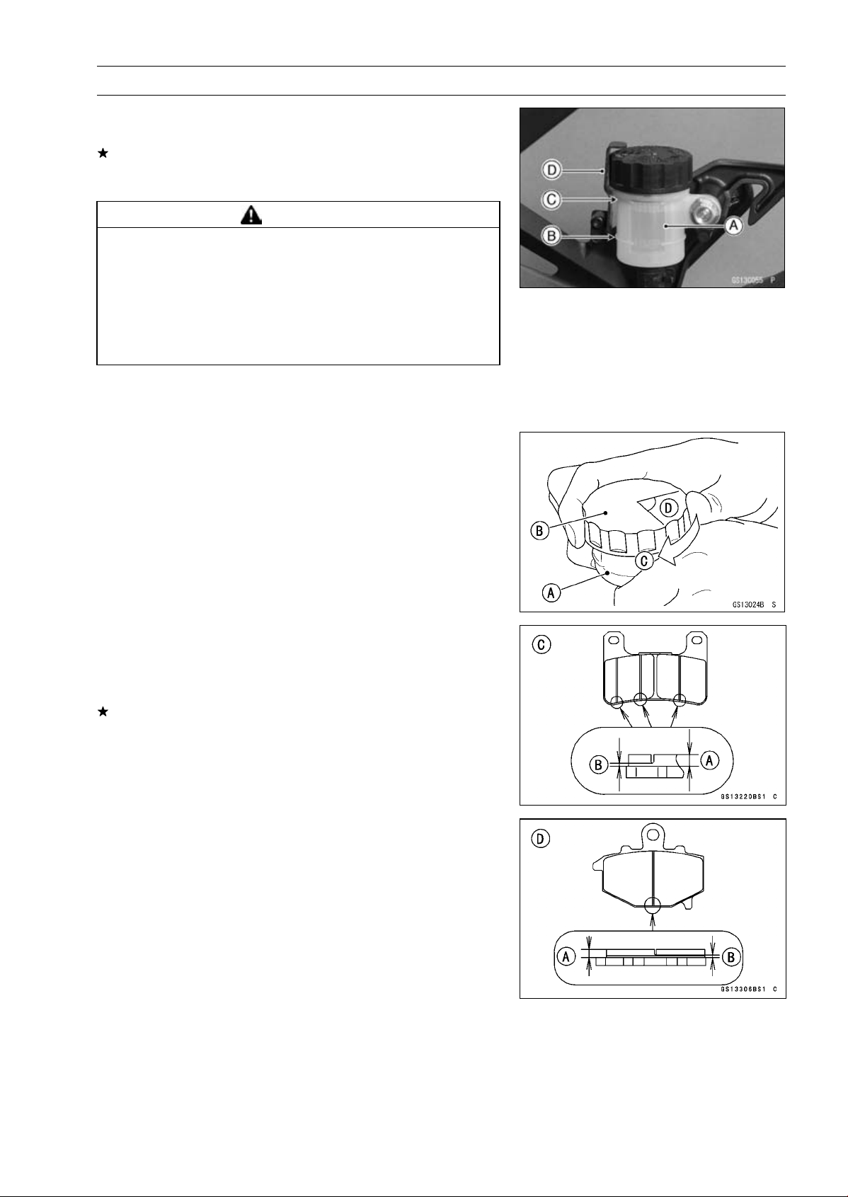
PERIODIC MAINTENANCE 2-37
Periodic Maintenance Procedures
•
Check that the brake fluid level in the rear brake reservoir
[A] is above the lower level line [B].
If the fluid level is lower than the lower level line, fill the
reservoir to the upper level line [C].
○
Remove the stopper [D].
WARNING
Mixing brands and types of brake fluid can reduce
the brake system’s effectiveness and cause an ac-
cident resulting in injury or death. Do not mix two
brands of brake fluid. Change the brake fluid in the
brake line completely if the brake fluid must be re-
filled but the type and brand of the brake fluid that
is already in the reservoir are unidentified.
Recommended Disc Brake Fluid
Grade: DOT4
•
Follow procedure below to install the rear brake fluid
reservoir cap correctly.
○
First, tighten the rear brake fluid reservoir cap [B] clock-
wise [C] by hand until slight resistance is felt indicating
that the cap is seated on the reservoir body, then tighten
the cap an additional 1/6 turn [D] while holding the brake
fluid reservoir body [A].
Brake Pad Wear Inspection
•
Remove the brake pads (see Front/Rear Brake Pad Re-
moval in the Brakes chapter).
•
Check the lining thickness [A] of the pads in each caliper.
If the lining thickness of either pad is less than the service
limit [B], replace both pads in the caliper as a set.
[C] Front Brake Pad
[D] Rear Brake Pad
Pad Lining Thickness
Standard:
Front 4.0 mm (0.16 in.)
Rear 5.0 mm (0.20 in.)
Service Limit: 1 mm (0.04 in.)
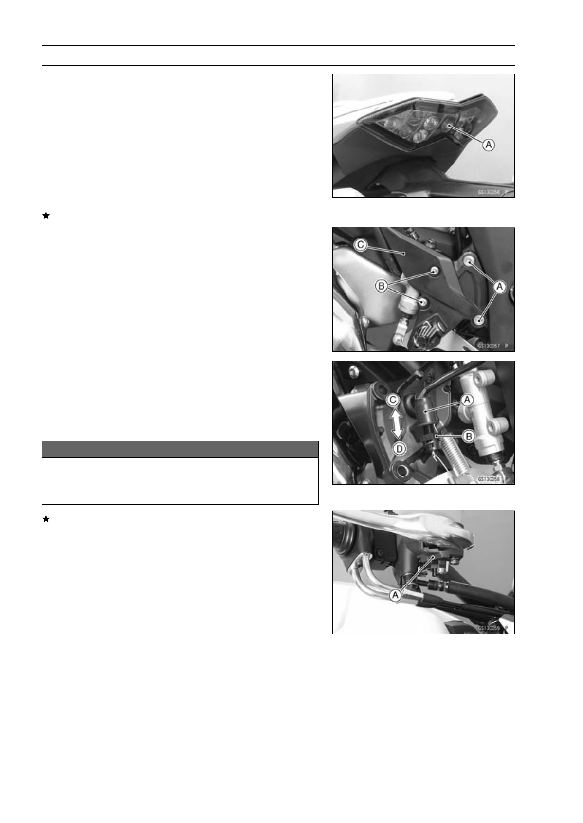
2-38 PERIODIC MAINTENANCE
Periodic Maintenance Procedures
Brake Light Switch Operation Inspection
•
Turn on the ignition switch.
•
The brake light [A] should go on when the brake lever is
applied or after the brake pedal is depressed about 10
mm (0.39 in.).
If it does not, adjust the brake light switch as follows.
•
Remove:
Rear Lower Fairing (see Rear Lower Fairing Removal in
the Frame chapter)
Footpeg Bracket Bolts [A]
Rear Master Cylinder Mounting Bolts [B]
Footpeg Bracket [C]
•
While holding the switch body, turn the adjusting nut to
adjust the switch.
Switch Body [A]
Adjusting Nut [B]
Light sooner as the body rises [C]
Light later as the body lowers [D]
NOTICE
To avoid damaging the electrical connections in-
side the switch, be sure that the switch body does
not turn during adjustment.
If it does not go on, inspect or replace the following items.
Battery (see Charging Condition Inspection in the Elec-
trical System chapter)
Brake Light (see Tail/Brake Light Removal in the Electri-
cal System chapter)
Main Fuse 30 A and Taillight Fuse 10 A (see Fuse In-
spection in the Electrical System chapter)
Front Brake Light Switch [A] (see Switch Inspection in
the Electrical System chapter)
Rear Brake Light Switch (see Switch Inspection in the
Electrical System chapter)
Harness (see Wiring Inspection in the Electrical System
chapter)
•
Tighten:
Torque - Front Footpeg Bracket Bolt: 25 N·m (2.5 kgf·m, 18
ft·lb)
Rear Master Cylinder Mounting Bolts: 25 N·m (2.5
kgf·m, 18 ft·lb)
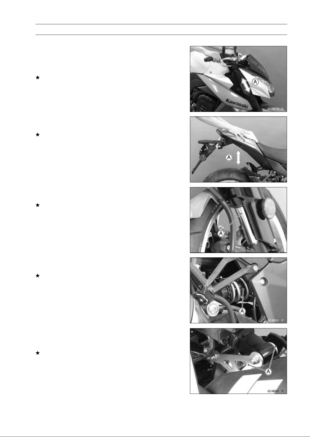
PERIODIC MAINTENANCE 2-39
Periodic Maintenance Procedures
Suspension
Front Forks/Rear Shock Absorber Operation
Inspection
•
Pump the forks down and up [A] 4 or 5 times, and inspect
the smooth stroke.
If the forks do not smoothly or noise is found, inspect the
fork oil level or fork clamps (see Front Fork Oil Change in
the Suspension chapter).
•
Pump the seat down and up [A] 4 or 5 times, and inspect
the smooth stroke.
If the shock absorber does not smoothly stroke or noise
is found, inspect the oil leak (see Rear Shock Absorber
Oil Leak Inspection).
Front Fork Oil Leak Inspection
•
Visually inspect the front forks [A] for oil leakage.
Replace any defective parts, if necessary.
Rear Shock Absorber Oil Leak Inspection
•
Visually inspect the shock absorber [A] for oil leakage.
If the oil leakage is found on it, replace the shock absorber
with a new one.
Rocker Arm Operation Inspection
•
Pump the seat down and up 4 or 5 times, and inspect the
smooth stroke.
If the rocker arms [A] do not smoothly stroke or noise is
found, inspect the fasteners and bearings (see Rocker
Arm/Tie-Rod Bearing, Sleeve Inspection in the Suspen-
sion chapter).

2-40 PERIODIC MAINTENANCE
Periodic Maintenance Procedures
Tie-Rod Operation Inspection
•
Pump the seat down and up 4 or 5 times, and inspect the
smooth stroke.
If the tie-rod [A] does not smoothly stroke or noise is
found, inspect the fasteners and tie-rod bearings (see
Rocker Arm/Tie-Rod Bearing, Sleeve Inspection in the
Suspension chapter).
Steering
Steering Play Inspection
•
Remove the rear lower fairings (see Rear Lower Fairing
Removal in the Frame chapter).
•
Raise the front wheel off the ground with the jack (see
Front Wheel Removal in the Wheels/Tires chapter).
•
With the front wheel pointing straight ahead, alternately
tap each end of the handlebar. The front wheel should
swing fully left and right from the force of gravity until the
fork hits the stop.
If the wheel binds or catches before the stop, the steering
is too tight.
•
Feel for steering looseness by pushing and pulling the
forks.
If you feel looseness, the steering is too loose.
NOTE
○
The cables and wiring will have some effect on the mo-
tion of the fork which must be taken into account.
○
Be sure the leads and cables are properly routed.
○
The bearings must be in good condition and properly
lubricated in order for any test to be valid.
Steering Play Adjustment
•
Remove:
Upper Fairing Bracket (see Upper Fairing Bracket Re-
moval in the Frame chapter)
Handlebar (see Handlebar Removal in the Steering
chapter)
Steering Stem Head Bolt Plug [A]
Steering Stem Head Bolt [B]
Upper Front Fork Clamp Bolts [C] (Loosen)
Stem Head [D]
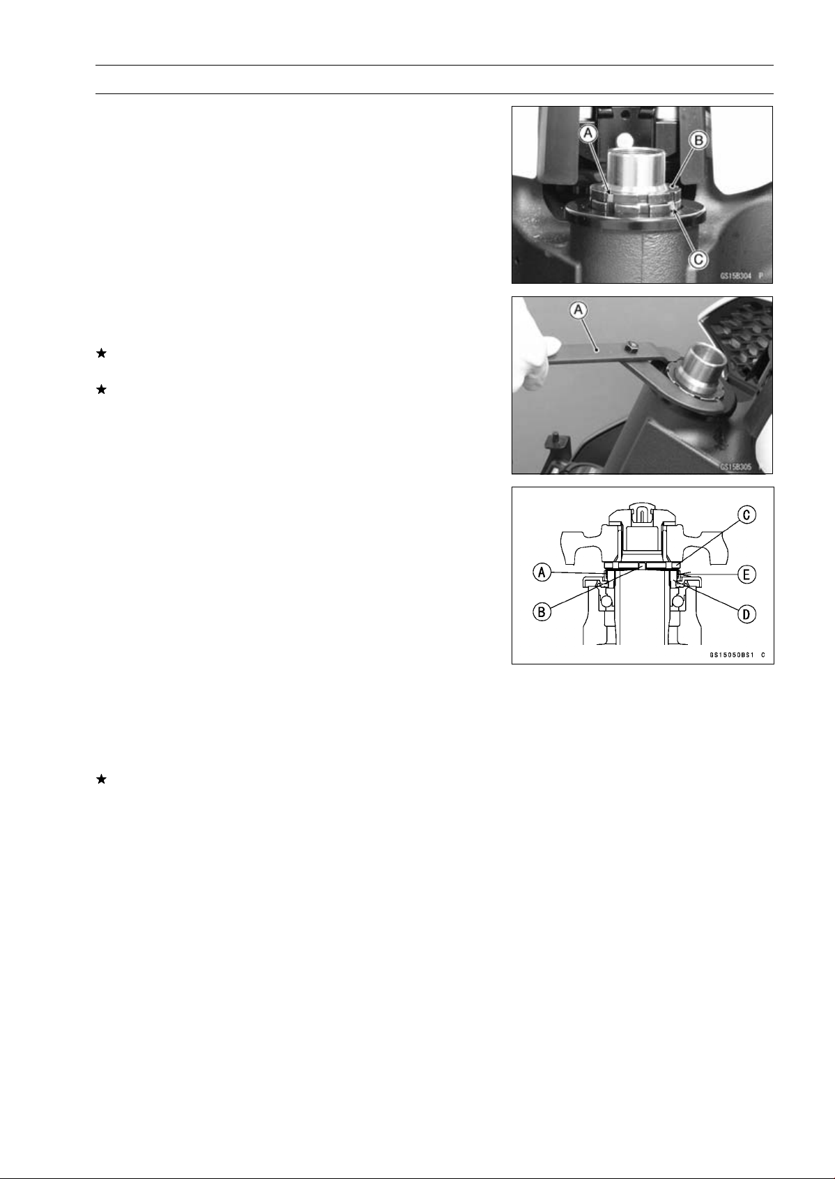
PERIODIC MAINTENANCE 2-41
Periodic Maintenance Procedures
•
Bend the claws [A] of the claw washer back.
•
Remove the steering stem locknut [B] and claw washer
[C].
•
Adjust the steering.
Special Tool - Steering Stem Nut Wrench [A]: 57001-1100
If the steering is too tight, loosen the stem nut a fraction
of a turn.
If the steering is too loose, tighten the stem nut a fraction
of a turn.
NOTE
○
Turn the stem nut 1/8 turn at time maximum.
•
Install the claw washer [A] so that its bent side [B] faces
upward, and engage the bent claws with the grooves of
stem locknut [C].
•
Hand tighten the stem locknut until the claw washer
touches the steering stem nut.
•
Tighten the stem locknut clockwise until the claws are
aligned with the grooves (ranging from 2nd to 4th) of stem
nut [D], and bend the 2 claws downward [E].
•
Install the stem head.
•
Tighten:
Torque - Steering Stem Head Bolt: 108 N·m (11.0 kgf·m,
79.7 ft·lb)
Upper Front Fork Clamp Bolts: 20 N·m (2.0 kgf·m,
15 ft·lb)
•
Check the steering again.
If the steering is still too tight or too loose, repeat the ad-
justment.
•
Install the removed parts (see appropriate chapters).
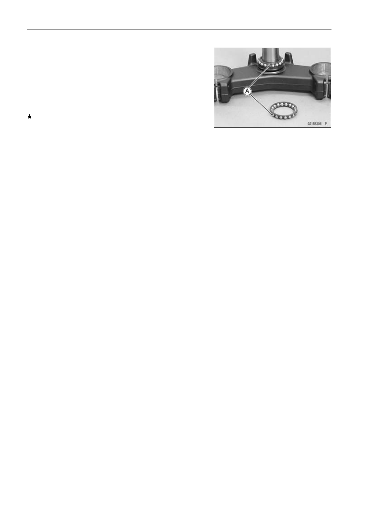
2-42 PERIODIC MAINTENANCE
Periodic Maintenance Procedures
Steering Stem Bearing Lubrication
•
Remove the steering stem (see Stem, Stem Bearing Re-
moval in the Steering chapter).
•
Using a high flash-point solvent, wash the upper and
lower ball bearings in the cages, and wipe the upper and
lower outer races, which are press-fitted into the frame
head pipe, clean off grease and dirt.
•
Visually check the outer races and the ball bearings.
Replace the bearing assemblies if they show wear or
damage.
•
Pack the upper and lower ball bearings [A] in the cages
with grease, and apply a light coat of grease to the upper
and lower outer races.
•
Install the steering stem (see Stem, Stem Bearing Instal-
lation in the Steering chapter).
•
Adjust the steering (see Steering Play Adjustment).
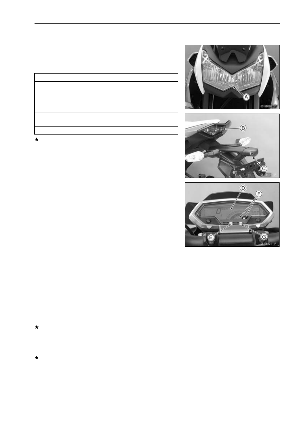
PERIODIC MAINTENANCE 2-43
Periodic Maintenance Procedures
Electrical System
Lights and Switches Operation Inspection
First Step
•
Turn on the ignition switch.
•
The following lights should go on according to below table.
City Light [A]
goes on
Taillight [B]
goes on
License Plate Light [C]
goes on
Meter Panel LCD [D]
goes on
Neutral Indicator Light (LED) [E]
goes on
Warning Symbol and Warning Indicator Light (LED)
[F]
flash
ABS Indicator Light (LED) [G] (ABS Equipped Models)
goes on
If the light does not go on, inspect or replace the following
item.
Battery (see Charging Condition Inspection in the Elec-
trical System chapter)
Main Fuse 30 A and Taillight Fuse 10 A (see Fuse In-
spection in the Electrical System chapter)
Applicable Bulb (see Wiring Diagram in the Electrical
System chapter)
Meter Unit for Meter Panel LCD (see Electronic Com-
bination Meter Unit Inspection in the Electrical System
chapter)
Meter Unit for Neutral Indicator Light (LED) (see Meter
Unit Inspection in the Electrical System chapter)
Meter Unit for Warning Indicator Light (LED) (see Meter
Unit Inspection in the Electrical System chapter)
ECU (see ECU Power Supply Inspection in the Fuel Sys-
tem (DFI) chapter)
Ignition Switch (see Switch Inspection in the Electrical
System chapter)
Neutral Switch (see Switch Inspection in the Electrical
System chapter)
Harness (see Wiring Inspection in the Electrical System
chapter)
ABS Indicator Light (LED) (ABS Equipped Models) (see
ABS Indicator Light (LED) Inspection in the Brakes chap-
ter)
•
Turn off the ignition switch.
•
The all lights should go off.
If the light does not go off, replace the ignition switch.
Second Step (
∼ ZR1000DC/EC)
•
Turn the ignition switch to P (Park) position.
•
The city light, taillight and license plate light should go on.
If the light does not go on, inspect or replace the following
item.
Ignition Switch (see Switch Inspection in the Electrical
System chapter)
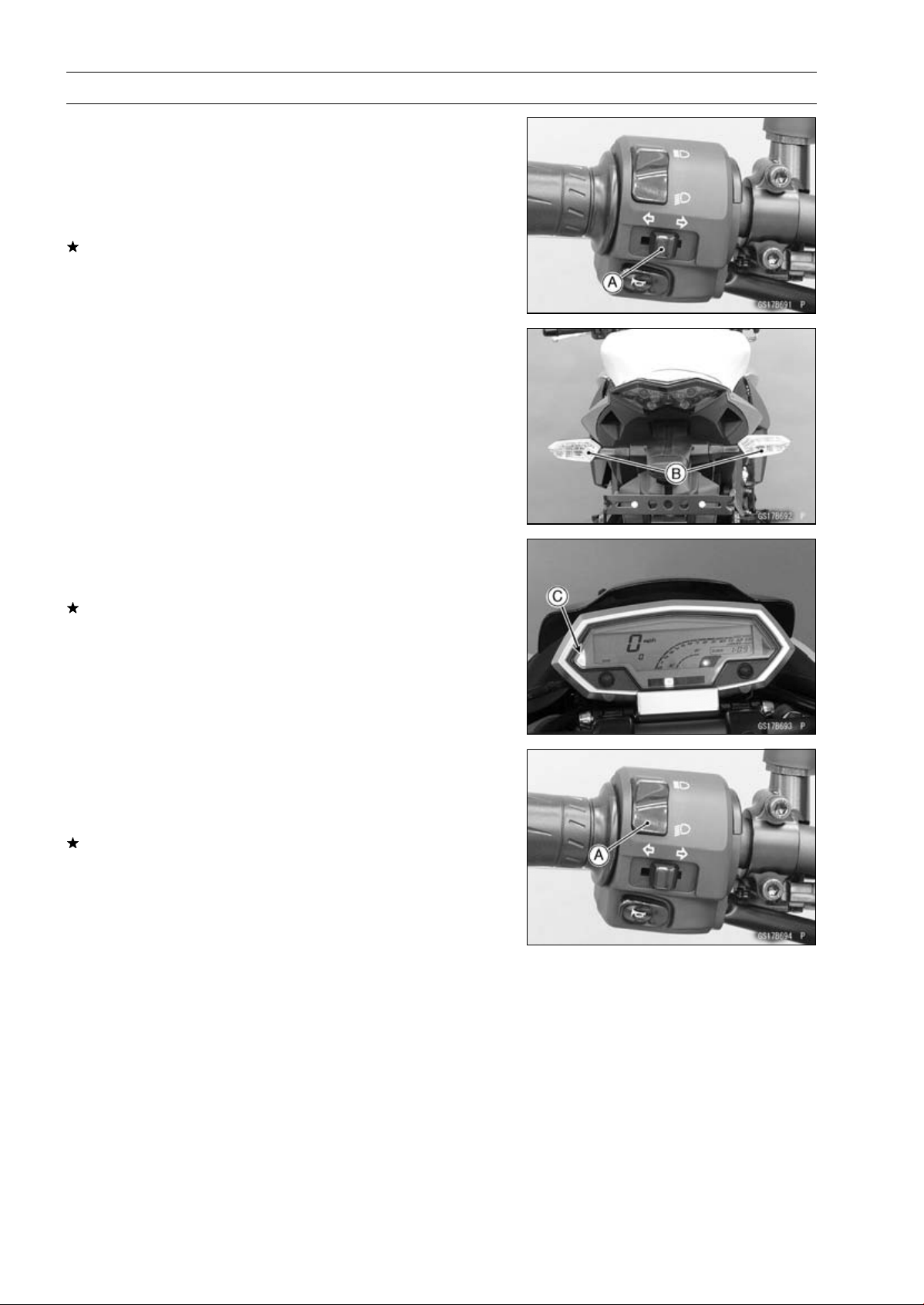
2-44 PERIODIC MAINTENANCE
Periodic Maintenance Procedures
Third Step
•
Turn on the turn signal switch [A] (left or right position).
•
The left or right turn signal lights [B] (front and rear) ac-
cording to the switch position should flash.
•
The turn signal indicator light (LED) [C] in the meter unit
should flash.
If the each light does not flash, inspect or replace the
following item.
Turn Signal Light Bulb (see Turn Signal Light Bulb Re-
placement in the Electrical System chapter)
Meter Unit for Turn Signal Light Indicator Light (LED)
(see Meter Unit Inspection in the Electrical System chap-
ter)
Turn Signal Relay Fuse 10 A (see Fuse Inspection in the
Electrical System chapter)
Turn Signal Switch (see Switch Inspection in the Electri-
cal System chapter)
Turn Signal Relay (see Turn Signal Relay Inspection in
the Electrical System chapter)
Harness (see Wiring Inspection in the Electrical System
chapter)
•
Push the turn signal switch.
•
The turn signal lights and indicator light (LED) should go
off.
If the light does not go off, inspect or replace the following
item.
Turn Signal Switch (see Switch Inspection in the Electri-
cal System chapter)
Fourth Step
•
Set the dimmer switch [A] to low beam position.
•
Start the engine.
•
The low beam headlight should go on.
If the low beam headlight does not go on, inspect or re-
place the following item.
Headlight Low Beam Bulb (see Headlight Bulb Replace-
ment in the Electrical System chapter)
Headlight Fuse 10 A (see Fuse Inspection in the Electri-
cal System chapter)
Dimmer Switch (see Switch Inspection in the Electrical
System chapter)
Headlight Relay in Relay Box (see Relay Circuit Inspec-
tion in the Electrical System chapter)
Harness (see Wiring Inspection in the Electrical System
chapter)
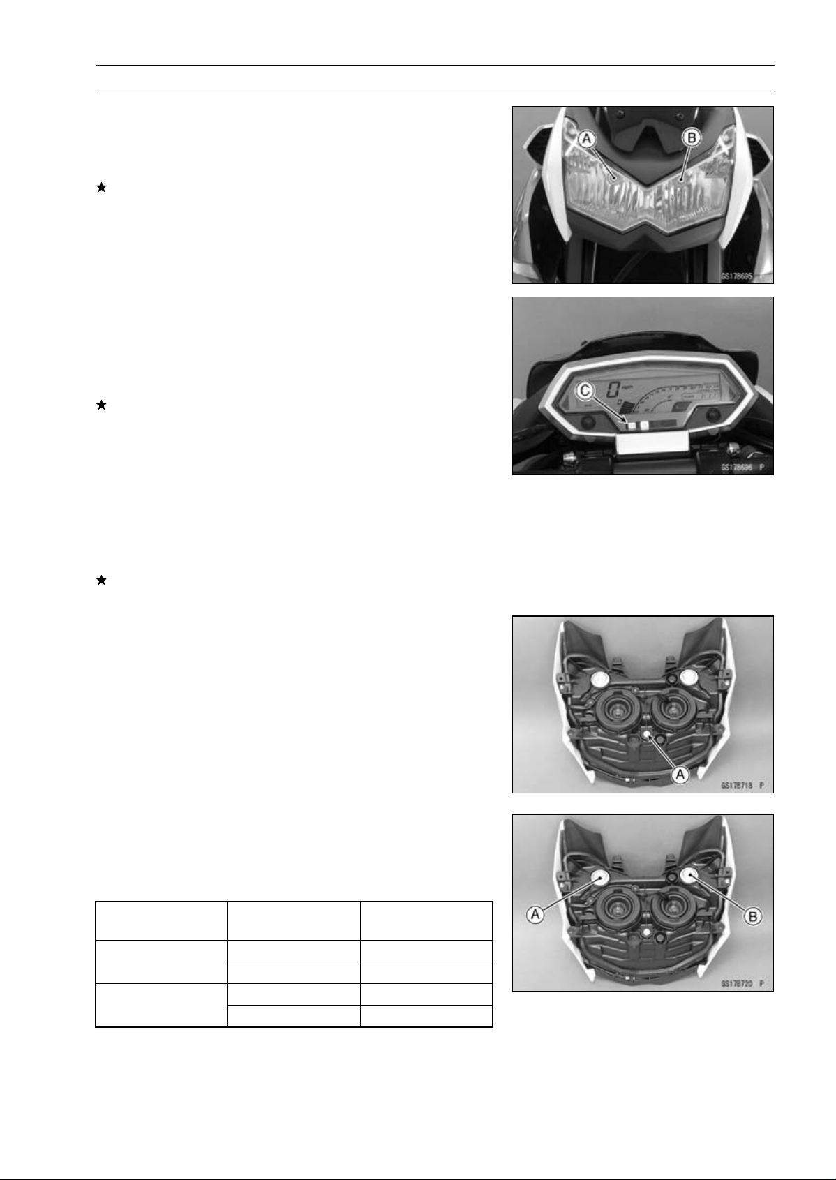
PERIODIC MAINTENANCE 2-45
Periodic Maintenance Procedures
•
Set the dimmer switch to high beam position.
•
The low beam [A] and high beam [B] headlights should
go on.
•
The high beam indicator light (LED) [C] should go on.
If the high beam headlight and/or high beam indicator light
(LED) does not go on, inspect or replace the following
item.
Headlight High Beam Bulb (see Headlight Bulb Replace-
ment in the Electrical System chapter)
Meter Unit for High Beam Indicator Light (LED) (see Me-
ter Unit Inspection in the Electrical System chapter)
Dimmer Switch (see Switch Inspection in the Electrical
System chapter)
•
Turn off the engine stop switch.
•
The low beam and high beam headlights should stay go-
ing on.
If the headlights and high beam indicator light (LED) does
go off, inspect or replace the following item.
Headlight Relay in Relay Box (see Relay Circuit Inspec-
tion in the Electrical System chapter)
•
Turn off the ignition switch.
•
The headlights and high beam indicator light (LED) should
go off.
Headlight Aiming Inspection
•
Inspect the headlight beam for aiming.
If the headlight beam is off the point, adjust the headlight
aiming.
Headlight Aiming Adjustment
NOTE
○
Do not turn the bolt [A] because the reflector in the
headlight comes off.
(In the photo, the headlight unit has been removed for
clarity.)
NOTE
○
The left adjuster [A] and right adjuster [B] can move the
direction of the headlight beam to up, down, left and
right by turning each adjuster itself as the below table.
Turning Direction
of Adjuster
Moving Direction of
Headlight Beam
Clockwise Left and Up
Left Adjuster
Counterclockwise
Right and Down
Clockwise
Right and Up
Right Adjuster
Counterclockwise Left and Down
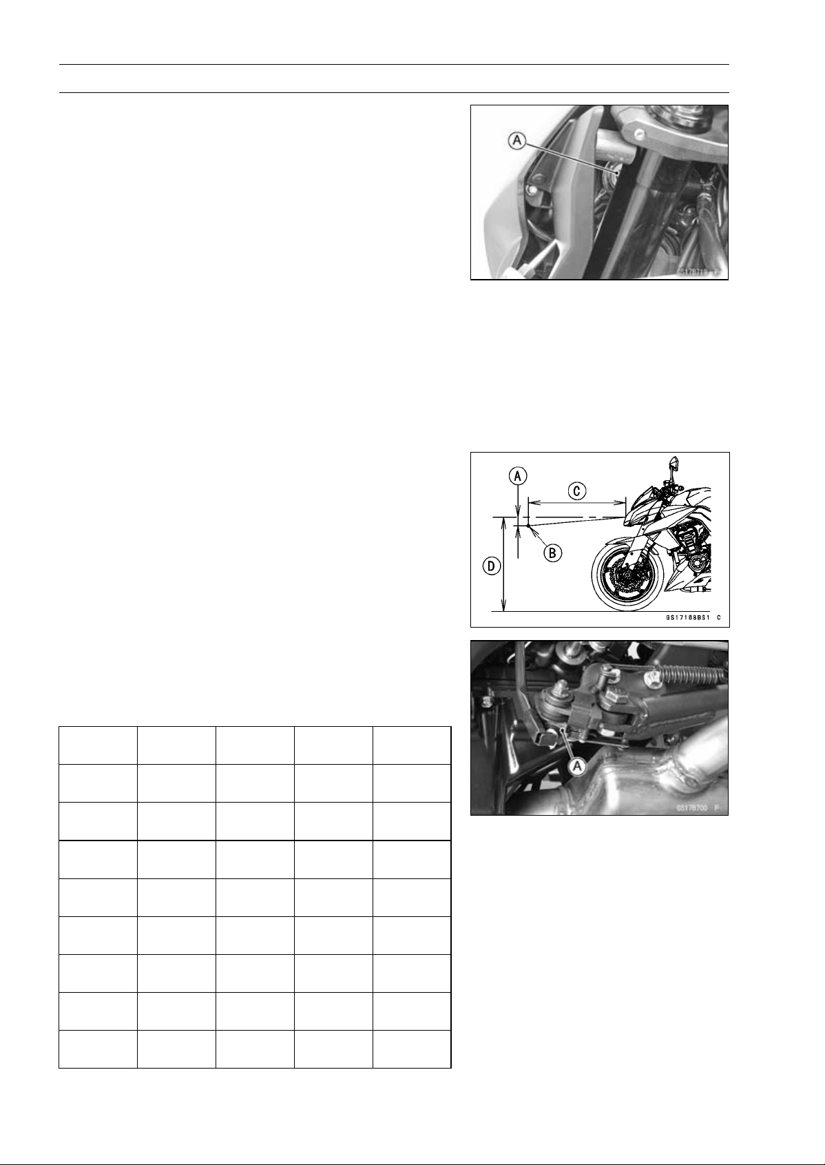
2-46 PERIODIC MAINTENANCE
Periodic Maintenance Procedures
•
To move the headlight beam leftward, turn the left ad-
juster [A] clockwise and turn the right adjuster counter-
clockwise same number as the left adjuster was turned
until the beam points straight ahead.
•
To move the headlight beam rightward, turn the left ad-
juster counterclockwise and turn the right adjuster clock-
wise same number as the left adjuster was turned until
the beam points straight ahead.
•
To move the headlight beam upward, turn the both ad-
justers clockwise same number.
•
To move the headlight beam downward, turn the both ad-
justers counterclockwise same number.
NOTE
○
On high beam, the brightest points should be slightly
below horizontal with the motorcycle on its wheels and
the rider seated. Adjust the headlight to the proper an-
gle according to local regulations.
NOTE
○
For US model, the proper angle is 0.4 degrees below
horizontal. This is 50 mm (2 in.) drop at 7.6 m (25
ft) measured from the center of the headlight with the
motorcycle on its wheels and the rider seated.
50 mm (2 in.) [A]
Center of Brightest Spot [B]
7.6 m (25 ft) [C]
Height of Headlight Center [D]
Sidestand Switch Operation Inspection
•
Inspect the sidestand switch [A] operation accordance to
the following table.
Sidestand Switch Operation
Sidestand
Gear
Position
Clutch
Lever
Engine
Start
Engine
Run
Up Neutral Released Starts
Continue
running
Up Neutral Pulled in Starts
Continue
running
Up In Gear Released
Doesn’t
start
Continue
running
Up In Gear Pulled in Starts
Continue
running
Down Neutral Released Starts
Continue
running
Down Neutral Pulled in Starts
Continue
running
Down
In Gear
Released
Doesn’t
start
Stops
Down
In Gear
Pulled in
Doesn’t
start
Stops
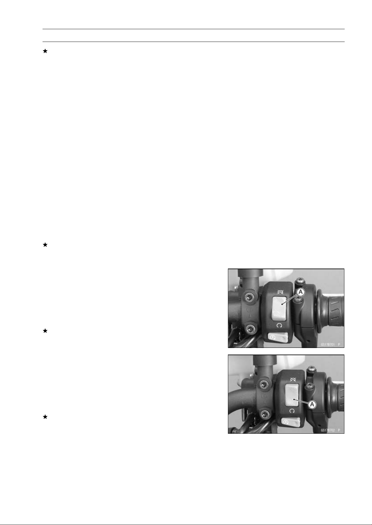
PERIODIC MAINTENANCE 2-47
Periodic Maintenance Procedures
If the sidestand switch operation does not work, inspect
or replace the following item.
Battery (see Charging Condition Inspection in the Elec-
trical System chapter)
Main Fuse 30 A (see Fuse Inspection in the Electrical
System chapter)
Ignition Fuse 15 A (see Fuse Inspection in the Electrical
System chapter)
Ignition Switch (see Switch Inspection in the Electrical
System chapter)
Sidestand Switch (see Switch Inspection in the Electrical
System chapter)
Engine Stop Switch (see Switch Inspection in the Elec-
trical System chapter)
Starter Button (see Switch Inspection in the Electrical
System chapter)
Neutral Switch (see Switch Inspection in the Electrical
System chapter)
Starter Relay (see Starter Relay Inspection in the Elec-
trical System chapter)
Relay Box (see Relay Circuit Inspection in the Electrical
System chapter)
Harness (see Wiring Inspection in the Electrical System
chapter)
If the all parts are good condition, replace the ECU (see
ECU Removal/Installation in the Fuel System (DFI) chap-
ter).
Engine Stop Switch Operation Inspection
First Step
•
Turn on the ignition switch.
•
Set the neutral position.
•
Turn the engine stop switch to stop position [A].
•
Push the starter button.
•
The engine does not start.
If the engine starts, inspect or replace the following item.
Engine Stop Switch (see Switch Inspection in the Elec-
trical System chapter)
Second Step
•
Turn on the ignition switch.
•
Set the neutral position.
•
Turn the engine stop switch to run position [A].
•
Push the starter button and run the engine.
•
Turn the engine stop switch to stop position.
•
Immediately the engine should be stop.
If the engine does not stop, inspect or replace the follow-
ing item.
Engine Stop Switch (see Switch Inspection in the Elec-
trical System chapter)
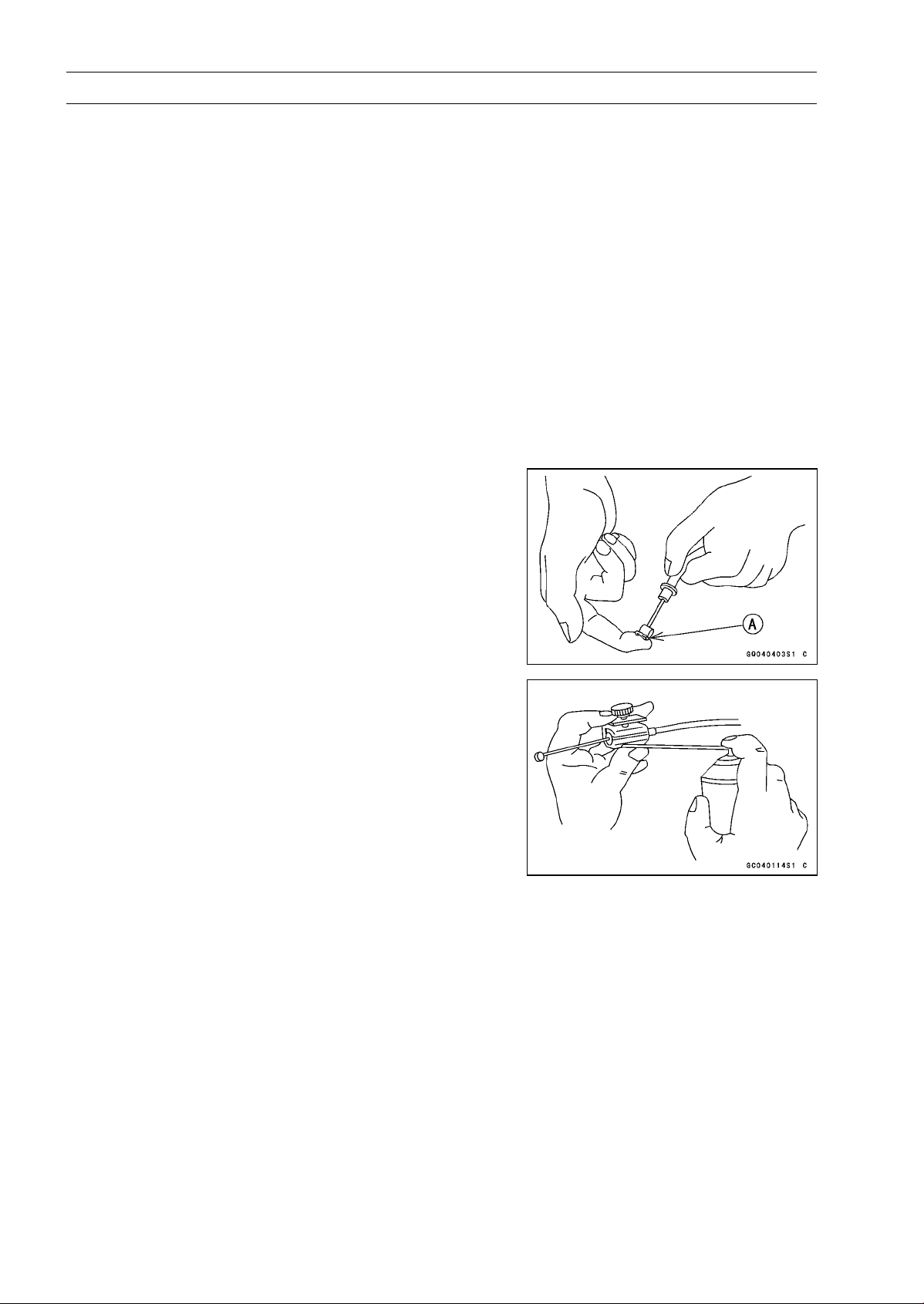
2-48 PERIODIC MAINTENANCE
Periodic Maintenance Procedures
Others
Chassis Parts Lubrication
•
Before lubricating each part, clean off any rusty spots with
rust remover and wipe off any grease, oil, dirt, or grime.
•
Lubricate the points listed below with indicated lubricant.
NOTE
○
Whenever the vehicle has been operated under
wet or rainy conditions, or especially after using a
high-pressure water spray, perform the general lubri-
cation.
Pivots: Lubricate with Grease.
Brake Lever
Brake Pedal
Clutch Lever
Rear Brake Joint Pin
Sidestand
Points: Lubricate with Grease.
Clutch Inner Cable Upper and Lower Ends [A]
Throttle Inner Cable Upper and Lower Ends
Cables: Lubricate with Rust Inhibitor.
Clutch Cable
Throttle Cables
•
Lubricate the cables by seeping the oil between the cable
and housing.
○
The cable may be lubricated by using a commercially
available pressure cable lubricator with an aerosol cable
lubricant.
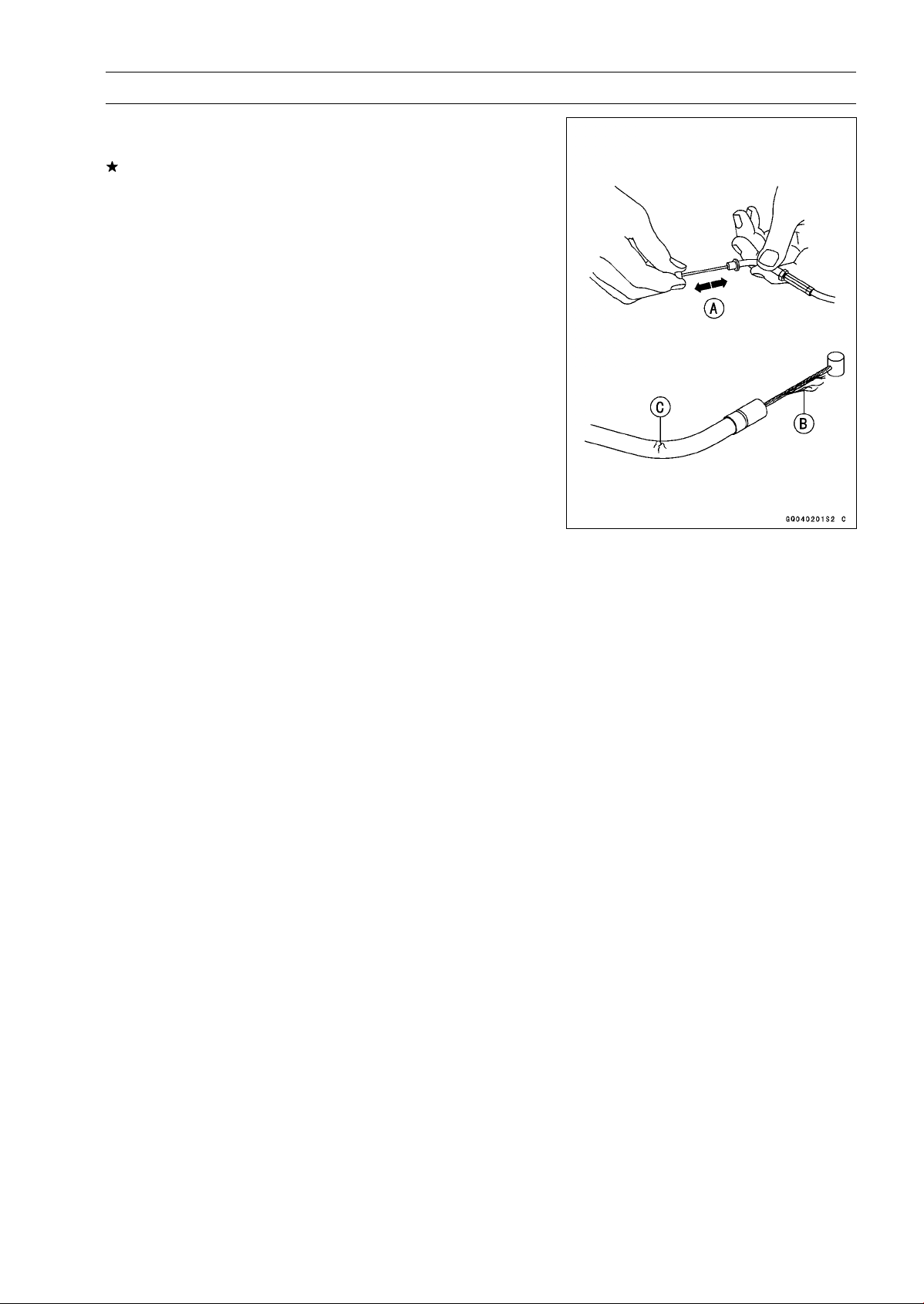
PERIODIC MAINTENANCE 2-49
Periodic Maintenance Procedures
•
With the cable disconnected at both ends, the cable
should move freely [A] within the cable housing.
If cable movement is not free after lubricating, if the cable
is frayed [B], or if the cable housing is kinked [C], replace
the cable.

2-50 PERIODIC MAINTENANCE
Periodic Maintenance Procedures
Bolts, Nuts and Fasteners Tightness Inspection
•
Check the tightness of the bolts and nuts listed here. Also,
check to see that each cotter pin is in place and in good
condition.
NOTE
○
For the engine fasteners, check the tightness of them
when the engine is cold (at room temperature).
If there are loose fasteners, retighten them to the spec-
ified torque following the specified tightening sequence.
Refer to the appropriate chapter for torque specifications.
If torque specifications are not in the appropriate chapter,
see the Standard Torque Table. For each fastener, first
loosen it by 1/2 turn, then tighten it.
If cotter pins are removed, replace them with new ones.
Bolt, Nut and Fastener to be checked
Engine:
Clutch Lever Pivot Bolt Locknut
Engine Mounting Bolts and Nuts
Exhaust Pipe Manifold Holder Nuts
Exhaust Pipe Mounting Bolt
Muffler Body Clamp Bolts
Muffler Body Mounting Bolt and Nuts
Radiator Upper and Lower Bolts
Subframe Bolts
Wheels:
Front Axle
Front Axle Clamp Bolt
Rear Axle Nut
Brakes:
Brake Lever Pivot Nut
Brake Pedal Bolt
Brake Rod Joint Cotter Pin
Caliper Mounting Bolts
Front Master Cylinder Clamp Bolts
Rear Master Cylinder Mounting Bolts
Suspension:
Front Fork Clamp Bolts
Rear Shock Absorber Bolt and Nut
Swingarm Pivot Shaft Locknut
Swingarm Pivot Shaft Nut
Tie-Rod Nuts
Rocker Arm Nut
Steering:
Handlebar Holder Bolts
Steering Stem Head Bolt
Others:
Footpeg Bracket Bolts
Front Fender Bolts
Sidestand Bolt
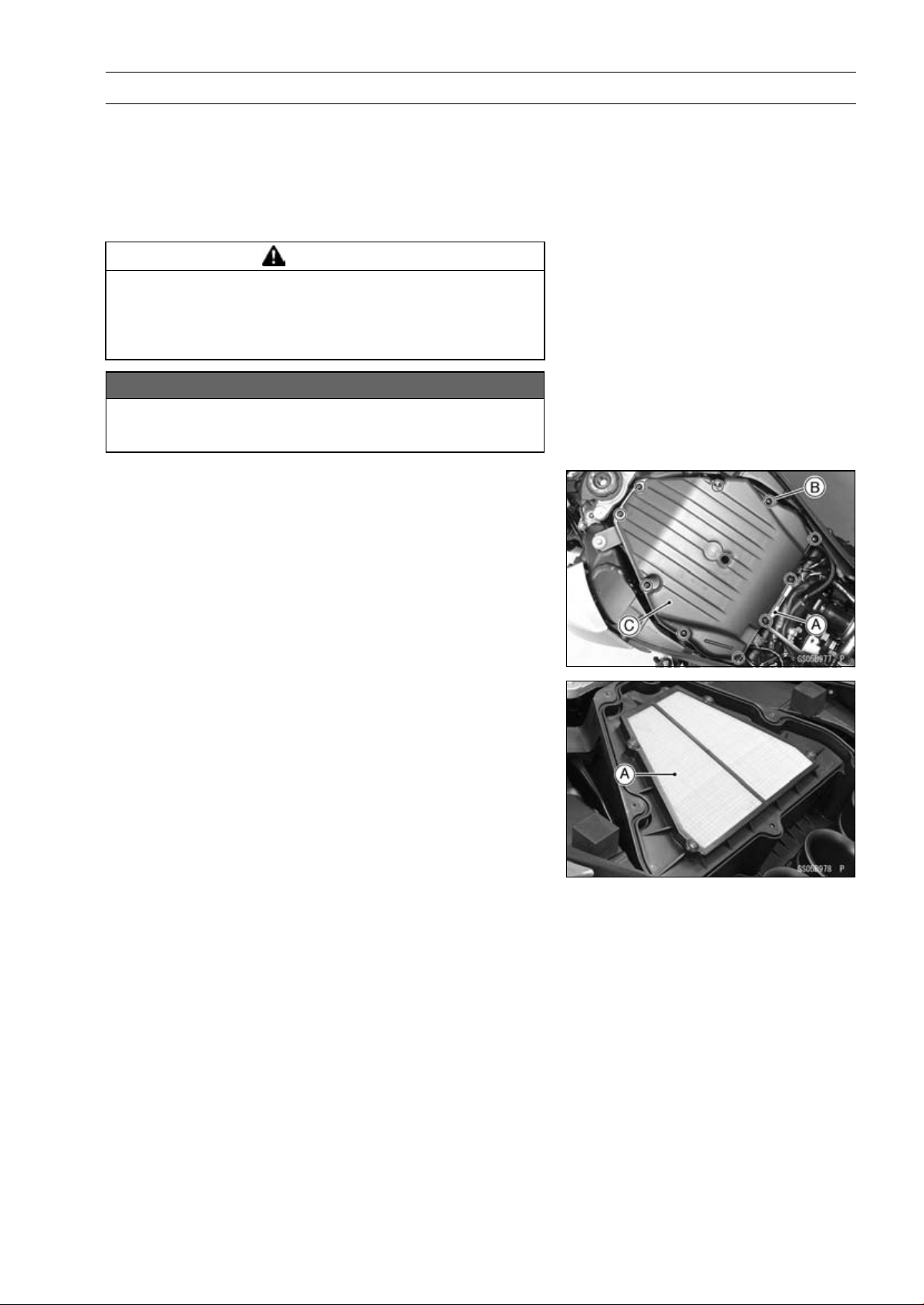
PERIODIC MAINTENANCE 2-51
Periodic Maintenance Procedures
Replacement Parts
Air Cleaner Element Replacement
NOTE
○
In dusty areas, the element should be replaced more
frequently than the recommended interval.
WARNING
If dirt or dust is allowed to pass through into the
throttle body assy, the throttle may become stuck,
possibly causing accident. Replace the air cleaner
element according to the maintenance chart.
NOTICE
If dirt gets through into the engine, excessive en-
gine wear and possibly engine damage will occur.
•
Remove:
Fuel Tank (see Fuel Tank Removal in the Fuel System
(DFI) chapter)
Connector Bracket [A]
Screws [B]
Upper Air Cleaner Housing [C]
•
Discard the air cleaner element [A].
•
Install a new element so that flat side faces forward.
•
Tighten:
Torque - Upper Air Cleaner Housing Screws: 1.1 N·m (0.11
kgf·m, 9.7 in·lb)
Fuel Hose Replacement
•
Remove the fuel tank (see Fuel Tank Removal in the Fuel
System (DFI) chapter).
•
Be sure to place a piece of cloth around the fuel hose joint.
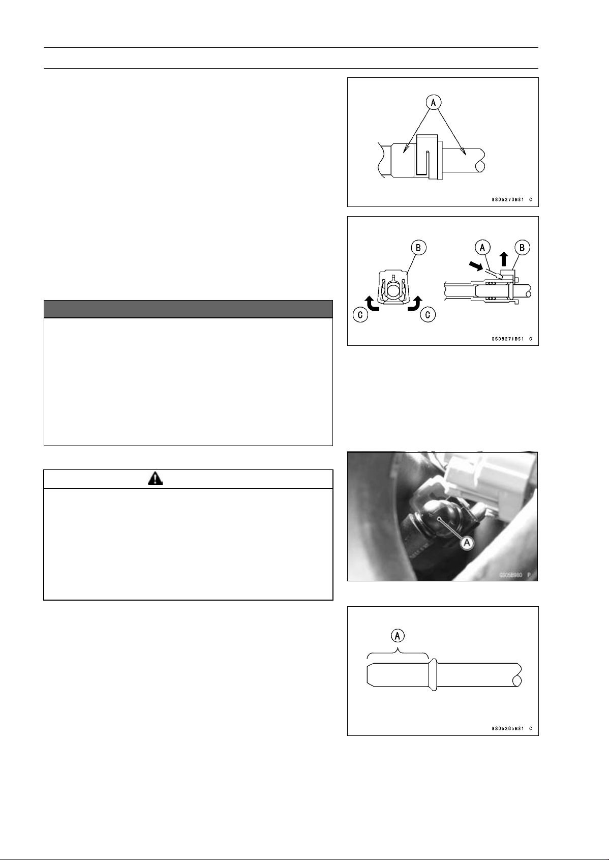
2-52 PERIODIC MAINTENANCE
Periodic Maintenance Procedures
•
Wipe off the dirt of the surface [A] around the connection
using a cloth or a soft brush.
When removing with standard tip screwdriver
•
Insert the standard tip screwdriver [A] into slit on the joint
lock [B].
•
Turn the driver to disconnect the joint lock.
When removing with fingers
•
Open and push up [C] the joint lock with your fingers.
NOTICE
Prying or excessively widening the joint lock ends
for fuel hose removal will permanently deform the
joint lock, resulting in a loose or incomplete lock
that may allow fuel to leak and create the potential
for a fire explosion. To prevent fire or explosion
from a damaged joint lock, do not pry or excessively
widen the joint lock ends when removing the fuel
hose. The joint lock has a retaining edge that locks
around the housing.
•
Pull the fuel hose joint [A] out of the delivery pipe.
WARNING
Fuel is flammable and explosive under certain con-
ditions and can cause severe burns. Be prepared
for fuel spillage; any spilled fuel must be completely
wiped up immediately. When the fuel hose is dis-
connected, fuel spills out from the hose and the
pipe because of residual pressure. Cover the hose
connection with a piece of clean cloth to prevent
fuel spillage.
•
Clean the delivery pipe.
•
Cover the delivery pipe with the vinyl bag to keep it clean.
•
Remove the vinyl bag on the pipe.
•
Check that there are no flaws, burrs, and adhesion of
foreign materials on the delivery pipe [A].
•
Replace the fuel hose with a new one.
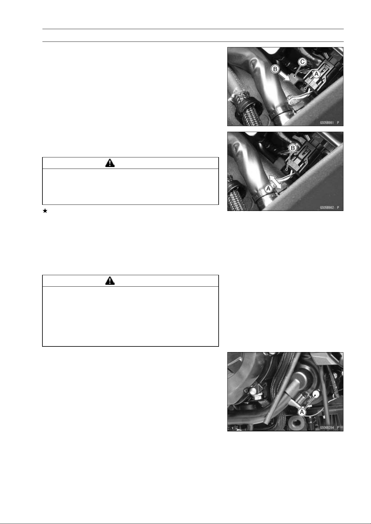
PERIODIC MAINTENANCE 2-53
Periodic Maintenance Procedures
•
Run the fuel hose correctly (see Cable, Wire, and Hose
Routing section in the Appendix chapter).
•
Insert the fuel hose joint [A] straight onto the delivery pipe
until the hose joint clicks.
•
Push [B] the joint lock [C].
•
Push and pull [A] the fuel hose joint [B] back and forth
more than two times and make sure it is locked and does
not come off.
WARNING
Leaking fuel can cause a fire or explosion resulting
in severe burns. Make sure the fuel hose joint is
installed correctly on the delivery pipe and that it
doesn’t leak.
If it comes off, reinstall the hose joint.
•
Run the fuel hose correctly (see Cable, Wire, and Hose
Routing section in the Appendix chapter).
•
Install the fuel tank (see Fuel Tank Installation in the Fuel
System (DFI) chapter).
•
Start the engine and check the fuel hose for leaks.
Coolant Change
WARNING
Coolant can be extremely hot and cause severe
burns, is toxic and very slippery. Do not remove
the radiator cap or attempt to change the coolant
when the engine is hot; allow it cool completely.
Immediately wipe any spilled coolant from tires,
frame, engine or other painted parts. Do not ingest
coolant.
•
Remove the left lower fairing (see Lower Fairing Removal
in the Frame chapter).
•
Place a container under the coolant drain bolt [A], then
remove the drain bolt.
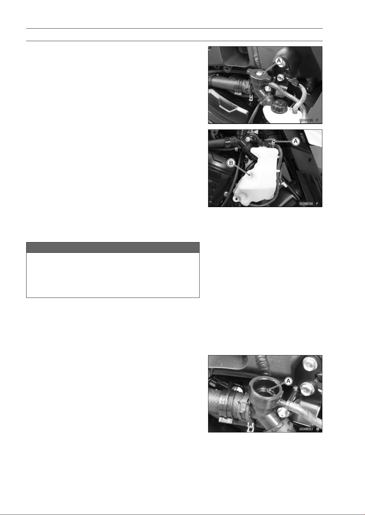
2-54 PERIODIC MAINTENANCE
Periodic Maintenance Procedures
•
Remove the right center fairing (see Center Fairing Re-
moval in the Frame chapter).
•
Remove the radiator cap [A] in two steps. First turn the
cap counterclockwise to the first stop. Then push and turn
it further in the same direction and remove the cap.
○
The coolant will drain from the radiator and engine.
•
Remove:
Right Seat Cover (see Seat Cover Removal in the Frame
chapter)
Hose [A]
Reserve Tank Bolt [B]
•
Turn over the reserve tank, remove the cap, and pour the
coolant into a suitable container.
•
Install the reserve tank.
•
Replace the drain bolt gasket with a new one.
•
Tighten the drain bolt with the gasket.
Torque - Coolant Drain Bolt: 11 N·m (1.1 kgf·m, 97 in·lb)
•
When filling the coolant, choose a suitable mixture ratio
by referring to the coolant manufacturer’s directions.
NOTICE
Soft or distilled water must be used with the an-
tifreeze in the cooling system.
If hard water is used in the system, it causes scales
accumulation in the water passages, and consider-
ably reduces the efficiency of the cooling system.
Water and Coolant Mixture Ratio (Recommended)
Soft Water: 50%
Coolant: 50%
Freezing Point:
–35°C (–31°F)
Total Amount:
2.9 L (3.1 US qt)
•
Fill the radiator up to the filler neck [A] with coolant.
NOTE
○
Pour in the coolant slowly so that it can expel the air
from the engine and radiator.
•
Check the cooling system for leaks.
•
Tap the radiator hoses to force any air bubbles caught
inside.
•
Fill the radiator up to the filler neck with coolant.

PERIODIC MAINTENANCE 2-55
Periodic Maintenance Procedures
•
Fill the reserve tank up to the “F” (full) level line [A] with
coolant and install the cap [B].
•
Start the engine, warm it up thoroughly until the radiator
fan turns on and then stop the engine.
•
Check the coolant level in the reserve tank after the en-
gine cools down.
If the coolant level is lower than the “L” (low) level line [C],
add coolant to the “F” level line.
NOTICE
Do not add more coolant above the “F” level line.
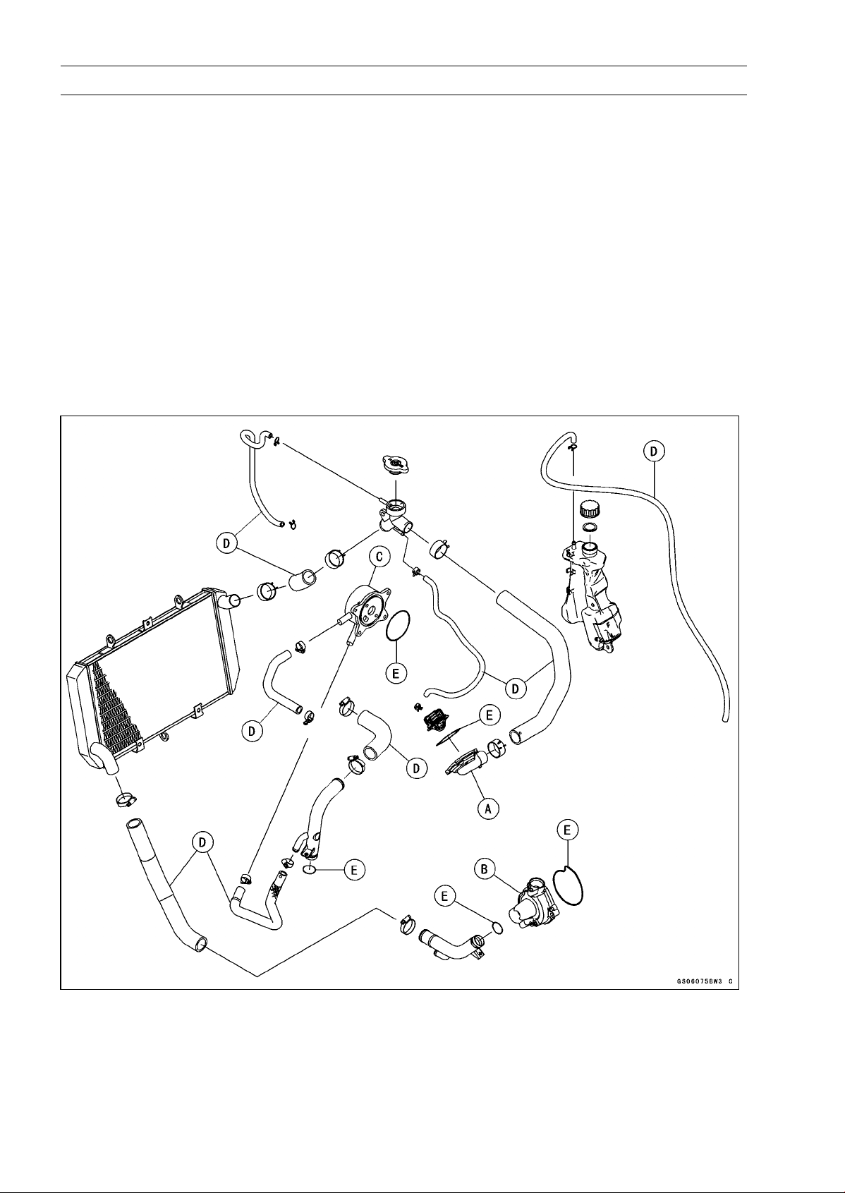
2-56 PERIODIC MAINTENANCE
Periodic Maintenance Procedures
Radiator Hose and O-ring Replacement
•
Drain the coolant (see Coolant Change).
•
Remove:
Thermostat Housing [A] (see Thermostat Removal in the
Cooling System chapter)
Water Pump Cover [B] (see Water Pump Removal in the
Cooling System chapter)
Oil Cooler [C] (see Oil Cooler Removal in the Engine
Lubrication System chapter)
•
Replace the hoses [D] and O-rings [E] with new ones.
•
Apply grease to the O-rings and install them.
•
Install the hoses and tighten the clamps securely.
Torque - Radiator (Water) Hose Clamp Screws: 2.9 N·m
(0.30 kgf·m, 26 in·lb)
•
Fill the coolant (see Coolant Change).
•
Check the cooling system for leaks.
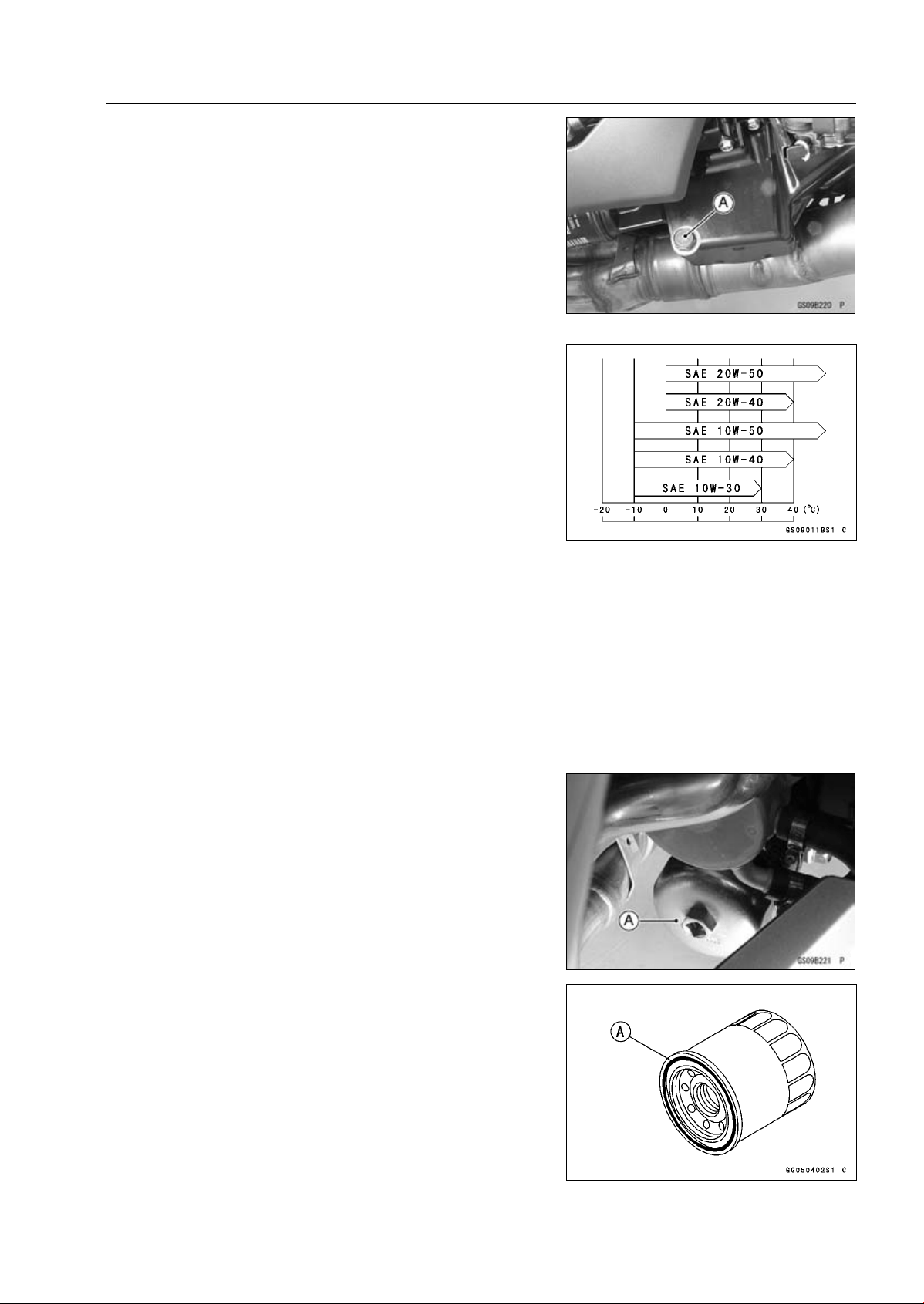
PERIODIC MAINTENANCE 2-57
Periodic Maintenance Procedures
Engine Oil Change
•
Situate the motorcycle so that it is vertical after warming
up the engine.
•
Remove the engine oil drain bolt [A] to drain the oil.
○
The oil in the oil filter can be drained by removing the filter
(see Oil Filter Replacement).
•
Replace the drain bolt gasket with a new one.
•
Tighten:
Torque - Engine Oil Drain Bolt: 29 N·m (3.0 kgf·m, 21 ft·lb)
•
Pour in the specified type and amount of oil.
Recommended Engine Oil
Type:
API SG, SH, SJ, SL or SM with JASO MA,
MA1 or MA2
Viscosity:
SAE 10W-40
Capacity: 3.2 L (3.4 US qt) (when filter is not
removed)
3.8 L (4.0 US qt) (when filter is removed)
4.0 L (4.2 US qt) (when engine is
completely dry)
NOTE
○
Do not add any chemical additive to the oil. Oils fulfilling
the above requirements are fully formulated and provide
adequate lubrication for both the engine and the clutch.
○
Although 10W-40 engine oil is the recommended oil
for most conditions, the oil viscosity may need to be
changed to accommodate atmospheric conditions in
your riding area.
•
Check the oil level (see Oil Level Inspection in the Engine
Lubrication System chapter).
Oil Filter Replacement
•
Drain the engine oil (see Engine Oil Change).
•
Remove the oil filter with the oil filter wrench [A].
Special Tool - Oil Filter Wrench: 57001-1249
•
Replace the filter with a new one.
•
Apply grease to the gasket [A] before installation.
•
Tighten the oil filter by hand temporarily.
•
Pour in the specified type and amount of oil (see Engine
Oil Change).
•
Loosen the oil filter to bleed the air and then tighten it with
the oil filter wrench.
Torque - Oil Filter: 17 N·m (1.7 kgf·m, 13 ft·lb)
NOTE
○
Hand tightening of the oil filter can not be allowed since
it does not reach to this tightening torque.
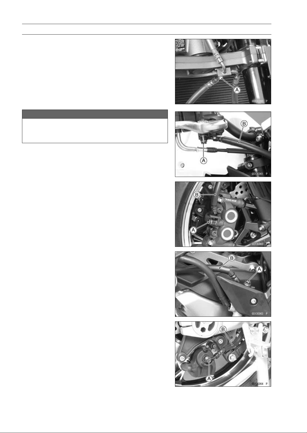
2-58 PERIODIC MAINTENANCE
Periodic Maintenance Procedures
Brake Hose Replacement
•
Remove:
Upper Fairing (see Upper Fairing Removal in the Frame
chapter)
Brake Hose Fitting Bolt [A]
NOTICE
Brake fluid quickly ruins painted plastic surfaces;
any spilled fluid should be completely washed away
immediately.
•
Remove the brake hose banjo bolts [A].
•
When removing the brake hose, take care not to spill the
brake fluid on the painted or plastic parts.
•
When removing the brake hoses [B], temporarily secure
the end of the brake hose to some high place to keep fluid
loss to a minimum.
•
Immediately wash away any brake fluid that spills.
○
There are washers on each side of the brake hose fitting.
•
Replace them with new ones when installing.
•
Fit the projection of the brake hose end to the calipers and
master cylinders, and tighten the brake hose banjo bolts.
Torque - Brake Hose Banjo Bolts: 25 N·m (2.5 kgf·m, 18
ft·lb)
•
When installing the hoses, avoid sharp bending, kink-
ing, flatting or twisting, and route the hoses according to
Cable, Wire, and Hose Routing section in the Appendix
chapter.
•
Fill the brake line after installing the brake hose (see
Brake Fluid Change).
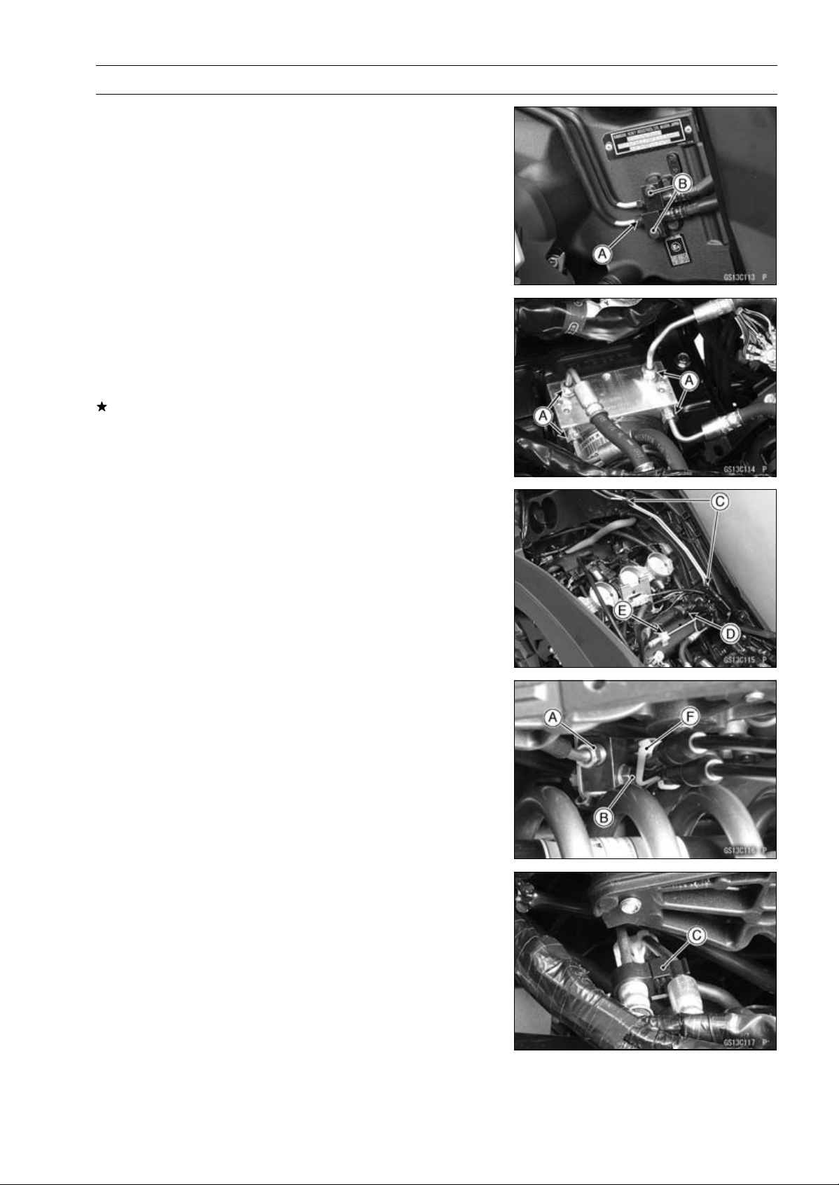
PERIODIC MAINTENANCE 2-59
Periodic Maintenance Procedures
•
For ABS equipped models; note the following.
•
Remove:
Air Cleaner Housing (see Air Cleaner Housing Removal
in the Fuel System (DFI) chapter)
Battery Case (see Battery Case Removal in the Frame
chapter)
Brake Pipe Joint Nuts [A]
Bolts [B]
Clamps [C]
•
Open the band [D].
•
Clear the brake pipe from the holder [E].
•
Remove the exhaust butterfly valve cable clamp [F].
•
There are washers on each side of the brake hose fitting.
Replace them with new ones when installing.
•
Before installing the brake pipe, check to see that there is
no damage on the threads of the brake pipe joint nut.
If there is any damage, replace the damaged parts with
new ones.
NOTE
○
Hand tighten the brake pipe joint nuts at both ends of
the brake pipe temporarily and then tighten them to the
specified torque.
○
Tighten the brake pipe joint nuts with the flare nut
wrench.
•
Tighten:
Torque - Brake Hose Banjo Bolts: 25 N·m (2.5 kgf·m, 18
ft·lb)
Brake Pipe Joint Nuts: 18 N·m (1.8 kgf·m, 13 ft·lb)
•
When installing the hoses, avoid sharp bending, kink-
ing, flatting or twisting, and route the hoses according to
Cable, Wire, and Hose Routing section in the Appendix
chapter.
•
Fill the brake line after installing the brake hose (see
Brake Fluid Change).

2-60 PERIODIC MAINTENANCE
Periodic Maintenance Procedures
Brake Fluid Change
NOTE
○
The procedure to change the front brake fluid is as fol-
lows. Changing the rear brake fluid is the same as for
the front brake.
•
Level the brake fluid reservoir.
•
Remove the reservoir cap.
•
Remove the rubber cap from the bleed valve [A] on the
caliper.
•
Attach a clear plastic hose [B] to the bleed valve, and run
the other end of the hose into a container.
•
Fill the reservoir with fresh specified brake fluid.
•
Change the brake fluid.
○
Repeat this operation until fresh brake fluid comes out
from the plastic hose or the color of the fluid changes.
1. Open the bleed valve [A].
2. Apply the brake and hold it [B].
3. Close the bleed valve [C].
4. Release the brake [D].
NOTE
○
The fluid level must be checked often during the chang-
ing operation and replenished with fresh brake fluid. If
the fluid in the reservoir runs out any time during the
changing operation, the brakes will need to be bled
since air will have entered the brake line.
○
Front Brake: Repeat the above steps for the other
caliper.
•
Tighten:
Torque - Front Master Cylinder Reservoir Cap Screws: 1.5
N·m (0.15 kgf·m, 13 in·lb)
•
Follow the procedure below to install the rear brake fluid
reservoir cap correctly.
○
First, tighten the rear brake fluid reservoir cap [B] clock-
wise [C] by hand until slight resistance is felt indicating
that the cap is seated on the reservoir body, then tighten
the cap an additional 1/6 turn [D] while holding the brake
fluid reservoir body [A].
•
Tighten the bleed valve, and install the rubber cap.
Torque - Bleed Valves: 7.8 N·m (0.80 kgf·m, 69 in·lb)
•
After changing the fluid, check the brake for good braking
power, no brake drag, and no fluid leakage.
If necessary, bleed the air from the lines.
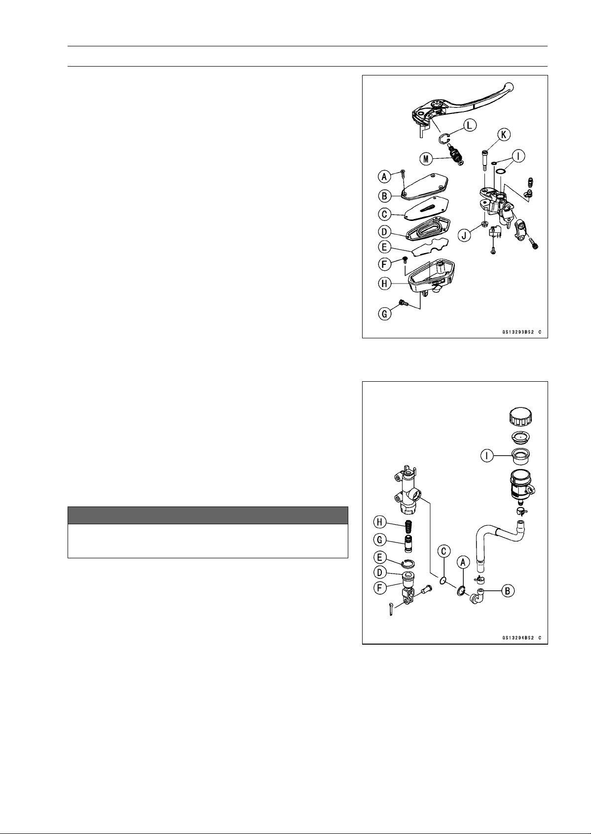
PERIODIC MAINTENANCE 2-61
Periodic Maintenance Procedures
Master Cylinder Rubber Parts Replacement
Front Master Cylinder Disassembly
•
Remove the front master cylinder (see Front Master Cylin-
der Removal in the Brakes chapter).
•
Remove:
Screws [A]
Cap [B]
Diaphragm Plate [C]
Diaphragm [D]
Float [E]
Screw [F]
Bolt [G]
•
Pull out the fluid reservoir [H] and O-rings [I].
•
Unscrew the locknut [J] and pivot bolt [K], and remove the
brake lever.
•
Remove the circlip [L].
Special Tool - Inside Circlip Pliers: 57001-143
•
Pull out the piston assy [M].
•
Replace:
Diaphragm [D]
O-ring [I]
Circlip [L]
Piston Assy [M]
Rear Master Cylinder Disassembly
•
Remove the rear master cylinder (see Rear Master Cylin-
der Removal in the Brakes chapter).
•
Remove the circlip [A], connector [B] and O-ring [C].
Special Tool - Inside Circlip Pliers: 57001-143
•
Slide the dust cover [D] out of place, and remove the cir-
clip [E].
•
Pull out the push rod assy [F].
•
Take off the piston assy [G] and return spring [H].
NOTICE
Do not remove the secondary cup from the piston
since removal will damage it.
•
Replace:
Circlip [A]
O-ring [C]
Circlip [E]
Push Rod Assy [F]
Piston Assy [G]
Diaphragm [I]
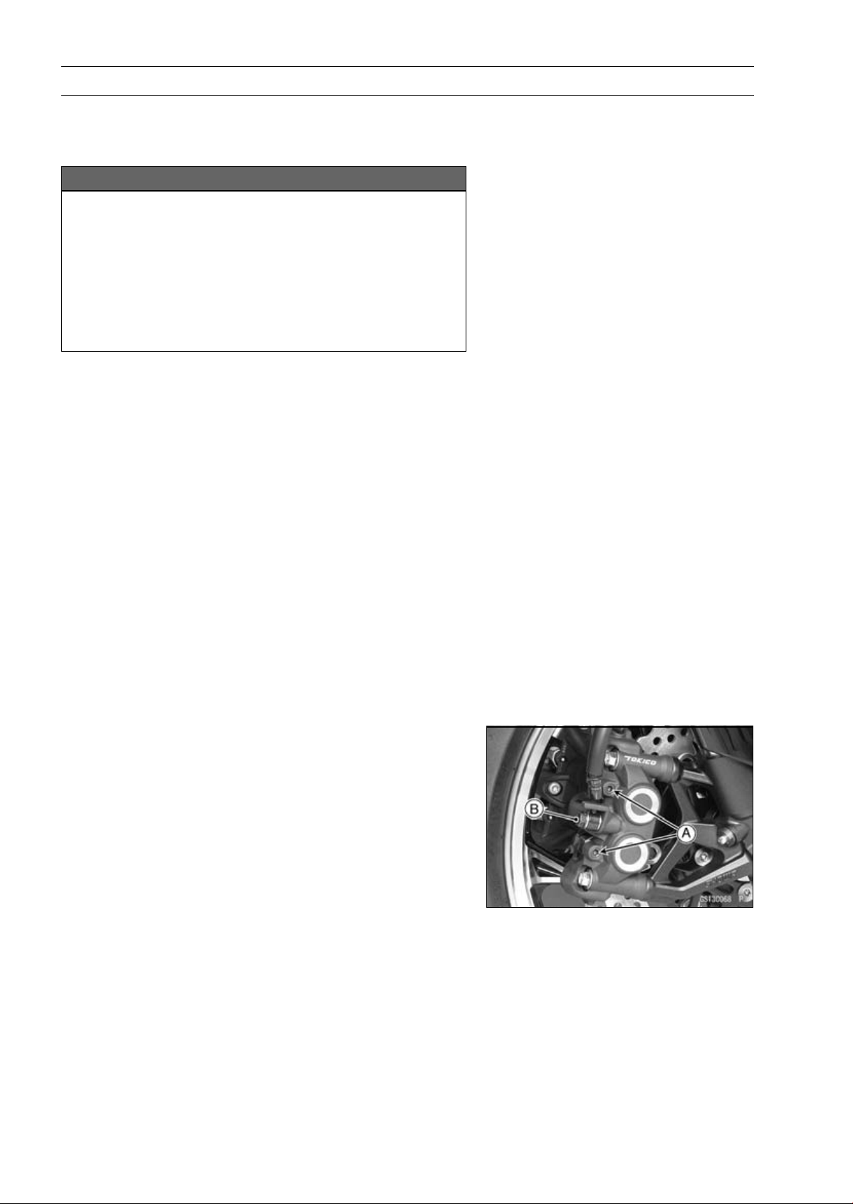
2-62 PERIODIC MAINTENANCE
Periodic Maintenance Procedures
Master Cylinder Assembly
•
Before assembly, clean all parts including the master
cylinder with brake fluid or alcohol.
NOTICE
Except for the disc pads and disc, use only disc
brake fluid, isopropyl alcohol, or ethyl alcohol for
cleaning brake parts. Do not use any other fluid for
cleaning these parts. Gasoline, engine oil, or any
other petroleum distillate will cause deterioration of
the rubber parts. Oil spilled on any part will be diffi-
cult to wash off completely, and will eventually de-
teriorate the rubber used in the disc brake.
•
Apply brake fluid to the new parts and to the inner wall of
the cylinder.
•
Take care not to scratch the piston or the inner wall of the
cylinder.
•
For the front master cylinder, apply a non-permanent lock-
ing agent to the reservoir screw and bolt.
•
Tighten:
Torque - Front Brake Reservoir Bolt: 7.8 N·m (0.80 kgf·m,
69 in·lb)
Front Brake Reservoir Screw: 1.2 N·m (0.12 kgf·m,
11 in·lb)
•
Apply silicone grease to the contact portion of the push
rod and brake lever pivot bolt.
•
Tighten:
Torque - Brake Lever Pivot Bolt: 1.0 N·m (0.10 kgf·m, 8.8
in·lb)
Brake Lever Pivot Bolt Locknut: 5.9 N·m (0.60
kgf·m, 52 in·lb)
Caliper Rubber Parts Replacement
Front Caliper Disassembly
•
Loosen the front caliper pad pins [A] and banjo bolt [B]
and tighten them loosely.
•
Remove:
Front Caliper (see Front Caliper Removal in the Brakes
chapter)
Brake Pads (see Front Brake Pad Removal in the brakes
chapter)
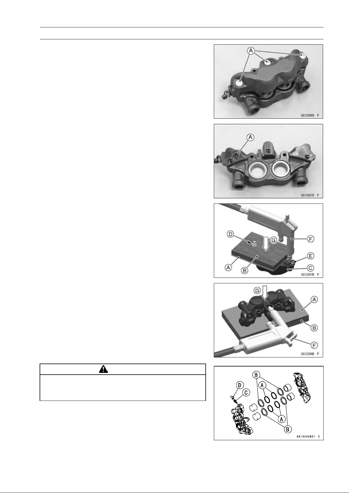
PERIODIC MAINTENANCE 2-63
Periodic Maintenance Procedures
•
Remove:
Front Caliper Assembly Bolts [A]
•
Split the front caliper.
•
Remove:
Pad Spring
O-ring [A]
•
Using compressed air, remove the pistons. One way to
remove the pistons is as follows.
○
Install a rubber gasket [A] and a wooden board [B] more
than 10 mm (0.4 in.) thick on the caliper half.
○
For inside caliper half [C], fasten them together with a
suitable bolt and nut [D] as shown. Leave one of the oil
passage [E] open.
○
Lightly apply compressed air [F] to the oil passage until
the pistons hit the rubber gasket.
Push down [G]
WARNING
The piston in the brake caliper can crush hands and
fingers. Never place your hand or fingers in front of
the piston.
○
Pull out the pistons by hand.
•
Remove the dust seals [A] and fluid seals [B].
•
Remove the bleed valve [C] and rubber cap [D].
•
Repeat the previous step to remove the pistons from the
other side of the caliper body.
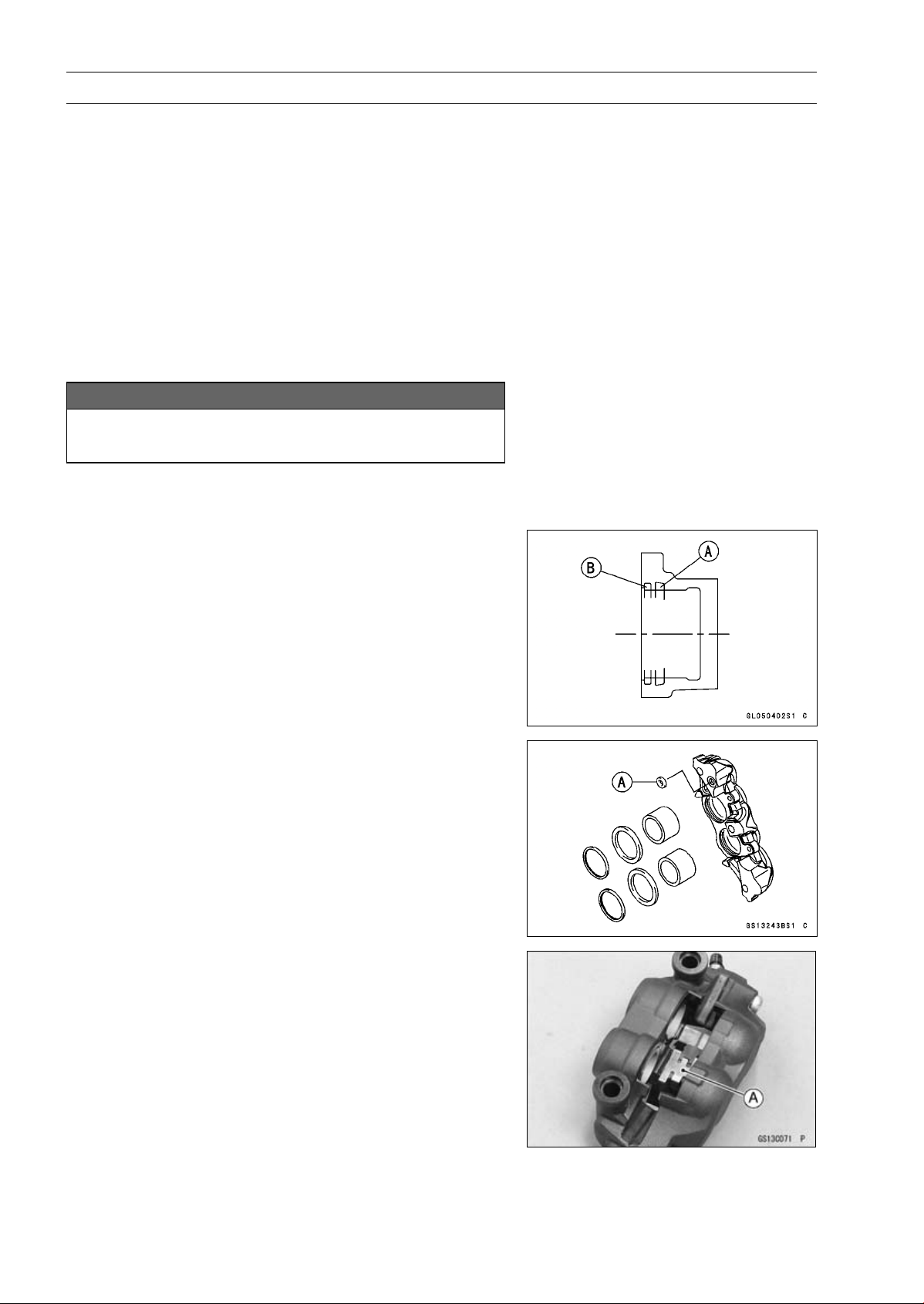
2-64 PERIODIC MAINTENANCE
Periodic Maintenance Procedures
NOTE
○
If compressed air is not available, do as follows for both
calipers coincidentally, with the brake hose connected
to the caliper.
○
Prepare a container for brake fluid, and perform the
work above it.
○
Remove the pad springs and pads (see Front Brake
Pad Removal in the Brakes chapter).
○
Pump the brake lever until the pistons come out of the
cylinders, and then disassemble the caliper.
Front Caliper Assembly
•
Clean the caliper parts except for the pads.
NOTICE
For cleaning the parts, use only disc brake fluid,
isopropyl alcohol, or ethyl alcohol.
•
Install the bleed valve and rubber cap.
Torque - Bleed Valves: 7.8 N·m (0.80 kgf·m, 69 in·lb)
•
Replace the fluid seals [A] with new ones.
○
Apply silicone grease to the fluid seals, and install them
into the cylinders by hand.
•
Replace the dust seals [B] with new ones if they are dam-
aged.
○
Apply silicone grease to the dust seals, and install them
into the cylinders by hand.
•
Replace the O-ring [A] and install it.
•
Apply brake fluid to the outside of the pistons, and push
them into each cylinder by hand.
•
Be sure to install the O-ring.
•
Tighten:
Torque - Front Caliper Assembly Bolts: 22 N·m (2.2 kgf·m,
16 ft·lb)
•
Install the pad spring [A] as shown.
•
Install the brake pads (see Front Brake Pad Installation in
the Brakes chapter).
•
Wipe up any spilled brake fluid on the caliper with wet
cloth.
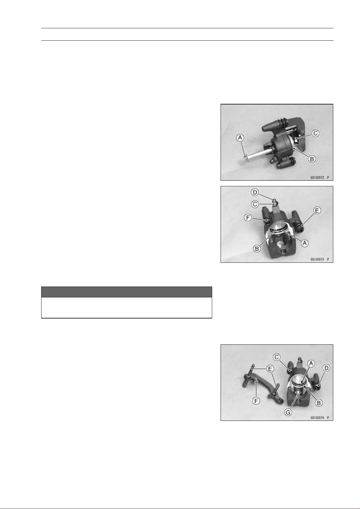
PERIODIC MAINTENANCE 2-65
Periodic Maintenance Procedures
Rear Caliper Disassembly
•
Remove:
Rear Caliper (see Rear Caliper Removal in the Brakes
chapter)
Brake Pads (see Rear Brake Pad Removal in the Brakes
chapter)
Caliper Holder
•
Using a rear caliper mounting bolt [A], screw the thread
hole for banjo bolt to remove the piston [B].
•
Remove the pad spring [C].
•
Remove:
Dust Seal [A] and Fluid Seal [B]
Bleed Valve [C] and Rubber Cap [D]
Dust Boot [E]
Friction Boot [F]
Rear Caliper Assembly
•
Clean the caliper parts except for the pads.
NOTICE
For cleaning the parts, use only disc brake fluid,
isopropyl alcohol, or ethyl alcohol.
•
Install the bleed valve and rubber cap.
Torque - Bleed Valve: 7.8 N·m (0.80 kgf·m, 69 in·lb)
•
Apply brake fluid to the cylinder bore.
•
Replace the fluid seal [A] with a new one.
○
Apply silicone grease to the fluid seal, and install it into
the cylinder by hand.
•
Replace the dust seal [B] with a new one.
•
Apply brake fluid to the outside of the piston, and push it
into the cylinder by hand as far as it will go.
•
Replace the friction boot [C] and dust boot [D] with new
ones.
•
Apply silicone grease to the sliding surface of the caliper
holder shafts [E].
•
Check that the guide [F] is in place on the caliper holder.
•
Install the pad spring [G].
•
Install the pads (see Rear Brake Pad Installation in the
Brakes chapter).
•
Wipe up any spilled brake fluid on the caliper with wet
cloth.
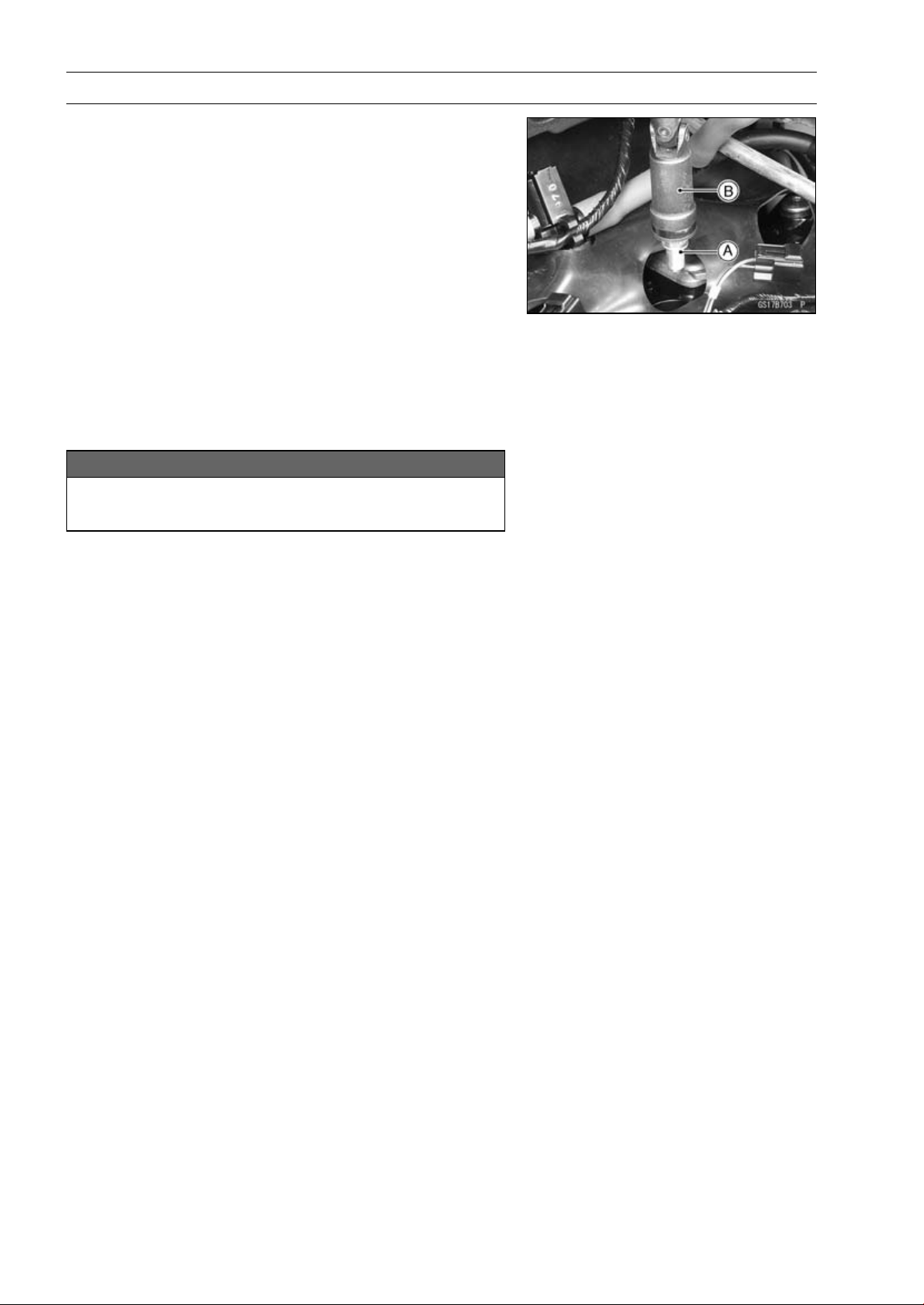
2-66 PERIODIC MAINTENANCE
Periodic Maintenance Procedures
Spark Plug Replacement
•
Remove the stick coils (see Stick Coil Removal in the
Electrical System chapter).
•
Remove the spark plugs [A] using the plug wrench [B]
vertically.
Special Tool - Spark Plug Wrench, Hex 16: 57001-1262
•
Replace the spark plug with a new one.
Standard Spark Plug
Type: NGK CR9EIA-9
•
Insert new spark plug in the plug wrench.
•
Using the plug wrench vertically, tighten the plug.
NOTICE
The insulator of the spark plug may break if when
the wrench is inclined during tightening.
Torque - Spark Plugs: 13 N·m (1.3 kgf·m, 115 in·lb)
•
Install the stick coils securely.
○
Be sure the stick coils are installed by pulling up it lightly.

FUEL SYSTEM (DFI) 3-1
3
Fuel System (DFI)
Table of Contents
Exploded View........................................................................................................................ 3-4
DFI System............................................................................................................................. 3-10
DFI Parts Location.................................................................................................................. 3-16
Specifications ......................................................................................................................... 3-18
Special Tools and Sealant ...................................................................................................... 3-20
DFI Servicing Precautions...................................................................................................... 3-22
DFI Servicing Precautions ................................................................................................... 3-22
Troubleshooting the DFI System ............................................................................................ 3-24
Outline ................................................................................................................................. 3-24
Inquiries to Rider.................................................................................................................. 3-28
DFI System Troubleshooting Guide ....................................................................................... 3-31
Self-Diagnosis ........................................................................................................................ 3-36
Self-diagnosis Outline.......................................................................................................... 3-36
Self-diagnosis Procedures................................................................................................... 3-37
Service Code Reading...................................................................................................... 3-39
Service Code Erasing ....................................................................................................... 3-40
Backups............................................................................................................................... 3-41
Main Throttle Sensor (Service Code 11) ................................................................................ 3-44
Main Throttle Sensor Removal/Adjustment ...................................................................... 3-44
Main Throttle Sensor Input Voltage Inspection ................................................................. 3-44
Main Throttle Sensor Output Voltage Inspection .............................................................. 3-45
Main Throttle Sensor Resistance Inspection .................................................................... 3-47
Intake Air Pressure Sensor #1 (Service Code 12).................................................................. 3-48
Intake Air Pressure Sensor #1 Removal........................................................................... 3-48
Intake Air Pressure Sensor #1 Installation........................................................................ 3-48
Intake Air Pressure Sensor #1 Input Voltage Inspection................................................... 3-49
Intake Air Pressure Sensor #1 Output Voltage Inspection................................................ 3-50
Intake Air Temperature Sensor (Service Code 13)................................................................. 3-54
Intake Air Temperature Sensor Removal/Installation........................................................ 3-54
Intake Air Temperature Sensor Output Voltage Inspection ............................................... 3-54
Intake Air Temperature Sensor Resistance Inspection..................................................... 3-55
Water Temperature Sensor (Service Code 14) ...................................................................... 3-57
Water Temperature Sensor Removal/Installation ............................................................. 3-57
Water Temperature Sensor Output Voltage Inspection..................................................... 3-57
Water Temperature Sensor Resistance Inspection........................................................... 3-58
Intake Air Pressure Sensor #2 (Service Code 16).................................................................. 3-59
Intake Air Pressure Sensor #2 Removal........................................................................... 3-59
Intake Air Pressure Sensor #2 Installation........................................................................ 3-59
Intake Air Pressure Sensor #2 Input Voltage Inspection................................................... 3-60
Intake Air Pressure Sensor #2 Output Voltage Inspection................................................ 3-61
Crankshaft Sensor (Service Code 21).................................................................................... 3-63
Crankshaft Sensor Removal/Installation........................................................................... 3-63
Crankshaft Sensor Resistance Inspection........................................................................ 3-63
Crankshaft Sensor Peak Voltage Inspection..................................................................... 3-63
Speed Sensor (Service Code 24, 25)..................................................................................... 3-64
Speed Sensor Removal/Installation.................................................................................. 3-64
Speed Sensor Input Voltage Inspection............................................................................ 3-64
Speed Sensor Output Voltage Inspection......................................................................... 3-65
Vehicle-down Sensor (Service Code 31)................................................................................ 3-67
Vehicle-down Sensor Removal......................................................................................... 3-67

3-2 FUEL SYSTEM (DFI)
Vehicle-down Sensor Installation...................................................................................... 3-68
Vehicle-down Sensor Input Voltage Inspection................................................................. 3-68
Vehicle-down Sensor Output Voltage Inspection.............................................................. 3-69
Subthrottle Sensor (Service Code 32).................................................................................... 3-72
Subthrottle Sensor Removal/Adjustment.......................................................................... 3-72
Subthrottle Sensor Input Voltage Inspection..................................................................... 3-72
Subthrottle Sensor Output Voltage Inspection.................................................................. 3-73
Subthrottle Sensor Resistance Inspection........................................................................ 3-75
Oxygen Sensor - not activated (Service Code 33, Equipped Models) ................................... 3-76
Oxygen Sensor Removal/Installation................................................................................ 3-76
Oxygen Sensor Inspection................................................................................................ 3-76
Exhaust Butterfly Valve Actuator Sensor (Service Code 34).................................................. 3-79
Exhaust Butterfly Valve Actuator Sensor Removal/Installation......................................... 3-79
Exhaust Butterfly Valve Actuator Sensor Input Voltage Inspection................................... 3-79
Exhaust Butterfly Valve Actuator Sensor Output Voltage Inspection ................................ 3-80
Exhaust Butterfly Valve Actuator Sensor Resistance Inspection ...................................... 3-81
Immobilizer Amplifier (Service Code 35, Equipped Models) .................................................. 3-82
Antenna Resistance Inspection ........................................................................................ 3-82
Amplifier Input Voltage Inspection..................................................................................... 3-83
Blank Key Detection (Service Code 36, Equipped Models) ................................................... 3-84
User Key (Ignition Key) Inspection.................................................................................... 3-84
ECU Communication Error (Service Code 39)....................................................................... 3-85
ECU Communication Line Inspection ............................................................................... 3-85
Stick Coils #1, #2, #3, #4 (Service Code 51, 52, 53, 54)........................................................ 3-86
Stick Coil Removal/Installation.......................................................................................... 3-86
Stick Coil Primary Winding Resistance Inspection ........................................................... 3-86
Stick Coil Input Voltage Inspection.................................................................................... 3-86
Radiator Fan Relay (Service Code 56)................................................................................... 3-88
Radiator Fan Relay Removal/Installation.......................................................................... 3-88
Radiator Fan Relay Inspection.......................................................................................... 3-88
Subthrottle Valve Actuator (Service Code 62) ........................................................................ 3-89
Subthrottle Valve Actuator Removal ................................................................................. 3-89
Subthrottle Valve Actuator Inspection ............................................................................... 3-89
Subthrottle Valve Actuator Resistance Inspection ............................................................ 3-89
Subthrottle Valve Actuator Input Voltage Inspection ......................................................... 3-90
Exhaust Butterfly Valve Actuator (Service Code 63) .............................................................. 3-92
Exhaust Butterfly Valve Actuator Removal ....................................................................... 3-92
Exhaust Butterfly Valve Actuator Installation .................................................................... 3-92
Exhaust Butterfly Valve Actuator Inspection ..................................................................... 3-94
Exhaust Butterfly Valve Actuator Resistance Inspection .................................................. 3-94
Air Switching Valve (Service Code 64) ................................................................................... 3-96
Air Switching Valve Removal/Installation .......................................................................... 3-96
Air Switching Valve Inspection .......................................................................................... 3-96
Oxygen Sensor Heater (Service Code 67, Equipped Models) ............................................... 3-97
Oxygen Sensor Heater Removal/Installation.................................................................... 3-97
Oxygen Sensor Heater Resistance Inspection ................................................................. 3-97
Oxygen Sensor Heater Power Source Voltage Inspection ............................................... 3-98
Oxygen Sensor - Incorrect Output Voltage (Service Code 94, Equipped Models)................. 3-100
Oxygen Sensor Removal/Installation................................................................................ 3-100
Oxygen Sensor Inspection................................................................................................ 3-100
Warning Indicator Light (LED) ................................................................................................ 3-103
Light (LED) Inspection ...................................................................................................... 3-103
ECU........................................................................................................................................ 3-104
ECU Identification ............................................................................................................. 3-104
ECU Removal ................................................................................................................... 3-104
ECU Installation ................................................................................................................ 3-105
ECU Power Supply Inspection.......................................................................................... 3-105

FUEL SYSTEM (DFI) 3-3
DFI Power Source .................................................................................................................. 3-108
ECU Fuse Removal .......................................................................................................... 3-108
ECU Fuse Installation ....................................................................................................... 3-108
ECU Fuse Inspection........................................................................................................ 3-108
ECU Main Relay Removal/Installation .............................................................................. 3-108
ECU Main Relay Inspection .............................................................................................. 3-108
Fuel Line................................................................................................................................. 3-109
Fuel Pressure Inspection .................................................................................................. 3-109
Fuel Flow Rate Inspection ................................................................................................ 3-110
Fuel Pump .............................................................................................................................. 3-112
Fuel Pump Removal ......................................................................................................... 3-112
Fuel Pump Installation ...................................................................................................... 3-113
Fuel Pump Operation Inspection ...................................................................................... 3-113
Fuel Pump Operating Voltage Inspection ......................................................................... 3-114
Pressure Regulator Removal............................................................................................ 3-114
Pump Screen, Fuel Filter Cleaning................................................................................... 3-115
Fuel Pump Relay Removal/Installation............................................................................. 3-115
Fuel Pump Relay Inspection............................................................................................. 3-115
Fuel Injectors.......................................................................................................................... 3-117
Fuel Injector Removal/Installation..................................................................................... 3-117
Fuel Injector Audible Inspection........................................................................................ 3-117
Fuel Injector Resistance Inspection.................................................................................. 3-117
Fuel Injector Power Source Voltage Inspection ................................................................ 3-118
Fuel Injector Output Voltage Inspection ............................................................................ 3-119
Fuel Injector Fuel Line Inspection..................................................................................... 3-120
Throttle Grip and Cables ........................................................................................................ 3-122
Free Play Inspection ......................................................................................................... 3-122
Free Play Adjustment........................................................................................................ 3-122
Cable Installation .............................................................................................................. 3-122
Cable Lubrication.............................................................................................................. 3-122
Throttle Body Assy ................................................................................................................. 3-123
Idle Speed Inspection/Adjustment .................................................................................... 3-123
Synchronization Inspection/Adjustment............................................................................ 3-123
Throttle Body Assy Removal............................................................................................. 3-123
Throttle Body Assy Installation.......................................................................................... 3-125
Throttle Body Assy Disassembly ...................................................................................... 3-126
Throttle Body Assy Assembly ........................................................................................... 3-127
Air Cleaner.............................................................................................................................. 3-128
Air Cleaner Element Removal/Installation ........................................................................ 3-128
Air Cleaner Element Inspection ........................................................................................ 3-128
Air Cleaner Oil Draining .................................................................................................... 3-128
Air Cleaner Housing Removal........................................................................................... 3-128
Air Cleaner Housing Installation........................................................................................ 3-129
Fuel Tank ................................................................................................................................ 3-130
Fuel Tank Removal ........................................................................................................... 3-130
Fuel Tank Installation ........................................................................................................ 3-134
Fuel Tank and Cap Inspection .......................................................................................... 3-135
Fuel Tank Cleaning ........................................................................................................... 3-136
Evaporative Emission Control System (CAL, SEA-B1 and TH Models)................................. 3-137
Parts Removal/Installation ................................................................................................ 3-137
Hose Inspection ................................................................................................................ 3-137
Separator Inspection......................................................................................................... 3-137
Separator Operation Test.................................................................................................. 3-138
Canister Inspection .......................................................................................................... 3-138
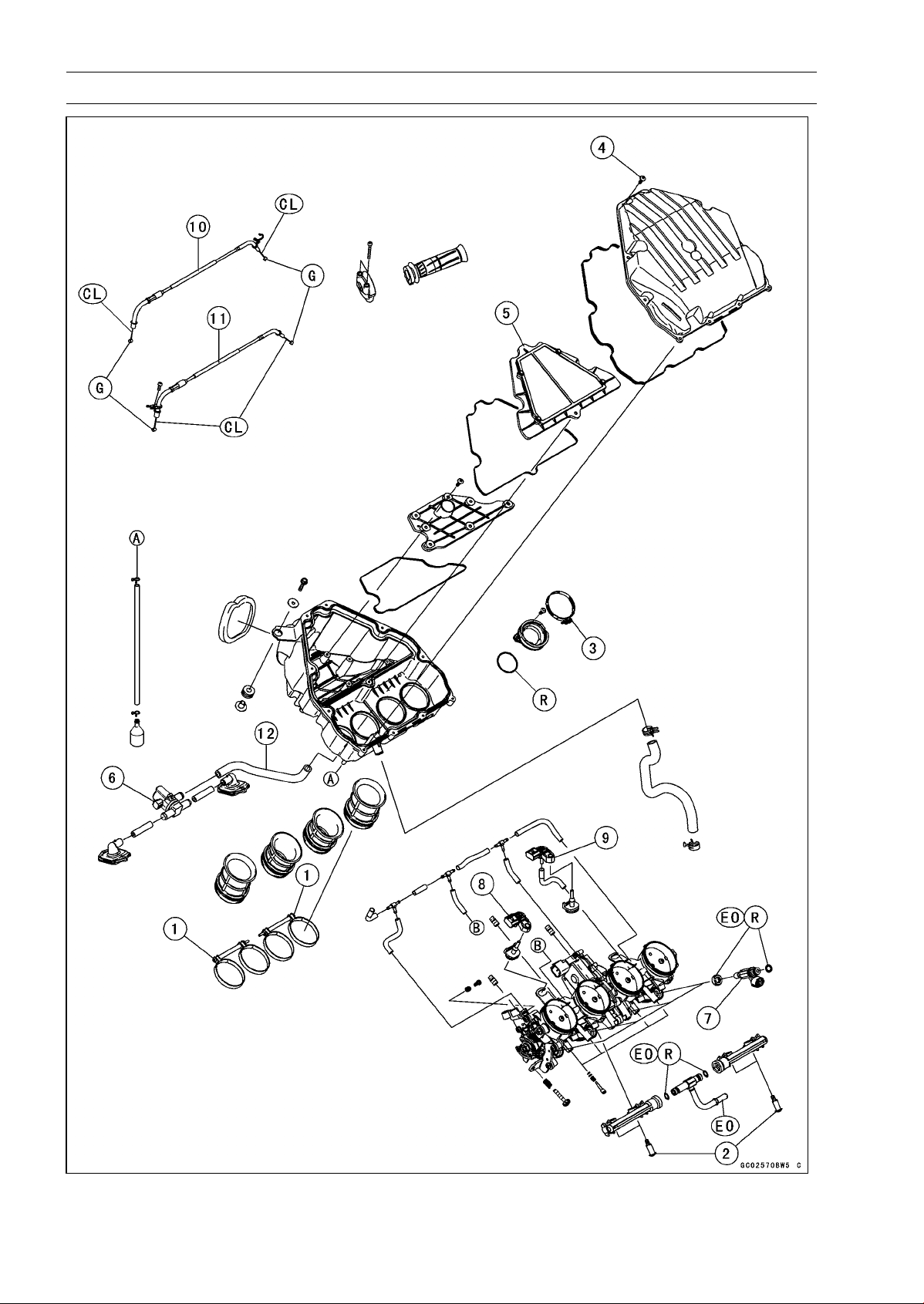
3-4 FUEL SYSTEM (DFI)
Exploded View

FUEL SYSTEM (DFI) 3-5
Exploded View
Torque
No. Fastener
N·m kgf·m ft·lb
Remarks
1 Air Cleaner Duct Clamp Bolts 2.0 0.20 18 in·lb
2 Delivery Pipe Assy Mounting Screws 3.4 0.35 30 in·lb
3
Throttle Body Assy Holder Clamp Bolts
2.9 0.30 26 in·lb
4 Upper Air Cleaner Housing Screws 1.1 0.11 9.7 in·lb
5. Air Cleaner Element
6. Air Switching Valve
7. Fuel Injectors
8. Intake Air Pressure Sensor #1
9. Intake Air Pressure Sensor #2
10. Throttle Cable (Accelerator, “-0303-” mark)
11. Throttle Cable (Decelerator, “-0275-” mark)
12. other than CAL, SEA-B1 and TH Models
CL: Apply cable lubricant.
EO: Apply engine oil.
G: Apply grease.
R: Replacement Parts
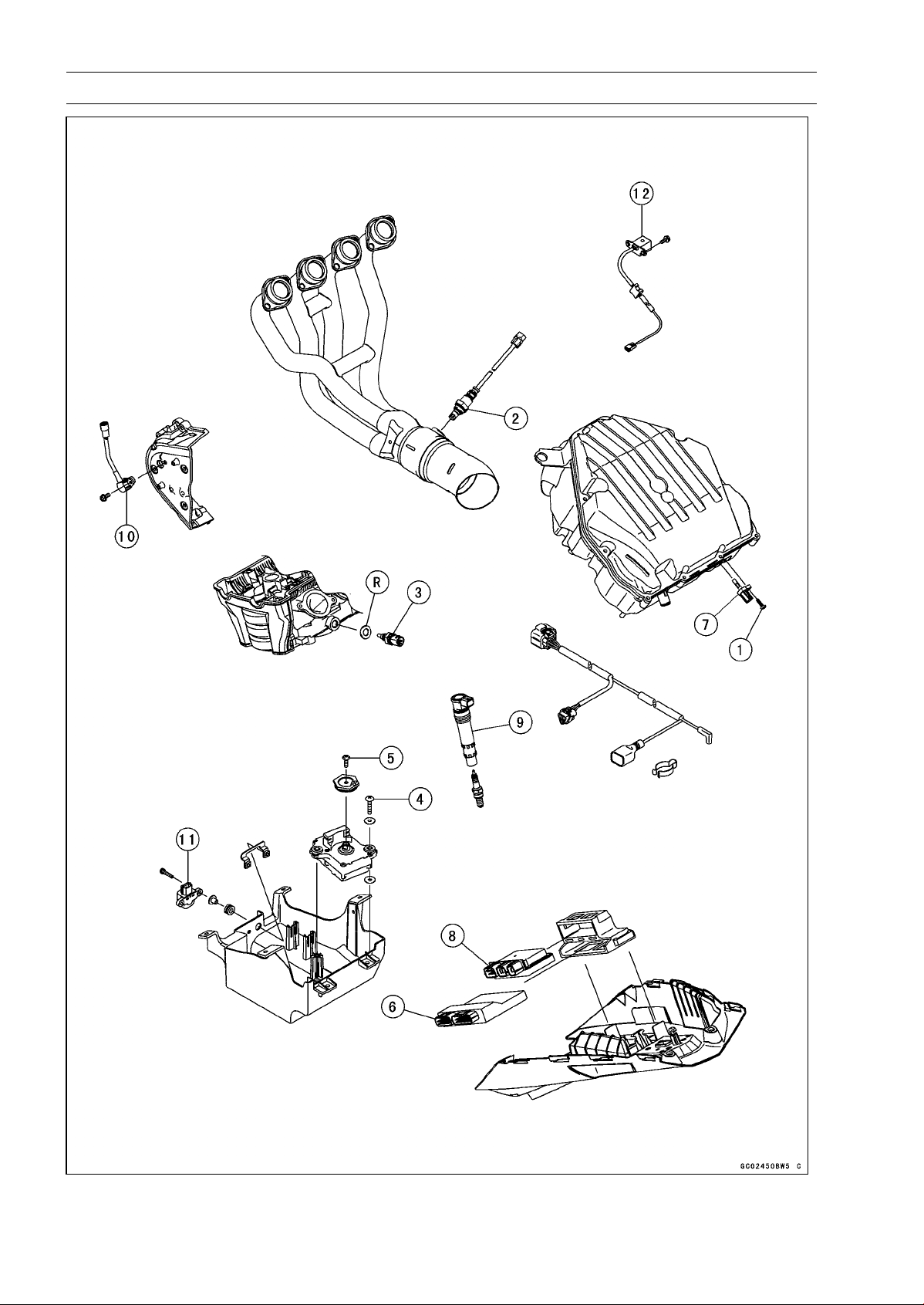
3-6 FUEL SYSTEM (DFI)
Exploded View

FUEL SYSTEM (DFI) 3-7
Exploded View
Torque
No. Fastener
N·m kgf·m ft·lb
Remarks
1 Intake Air Temperature Sensor Screw 1.2 0.12 11 in·lb
2 Oxygen Sensor (Equipped Models) 44 4.5 32
3
Water Temperature Sensor
30 3.1 22
4
Exhaust Butterfly Valve Actuator Mounting
Screws
1.2 0.12 11 in·lb
5
Exhaust Butterfly Valve Actuator Pulley Bolt
5.0 0.51 44 in·lb
6. ECU
7. Intake Air Temperature Sensor
8. Relay Box
9. Stick Coils
10. Speed Sensor
11. Vehicle-down Sensor
12. Crankshaft Sensor
R: Replacement Parts
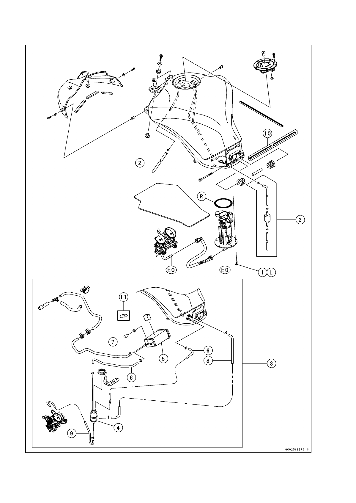
3-8 FUEL SYSTEM (DFI)
Exploded View

FUEL SYSTEM (DFI) 3-9
Exploded View
Torque
No. Fastener
N·m kgf·m ft·lb
Remarks
1 Fuel Pump Bolts 9.8 1.0 87 in·lb L
2. Other than CAL, SEA-B1 and TH Models
3. CAL, SEA-B1 and TH Models
4. Separator
5. Canister
6. Blue Hose
7. Green Hose
8. Red Hose
9. White Hose
10. Frame No. ∼ JKAZRT00DA017291
11. Frame No. ∼ JKAZRT00DA017568
EO: Apply engine oil.
L: Apply a non-permanent locking agent.
R: Replacement Parts
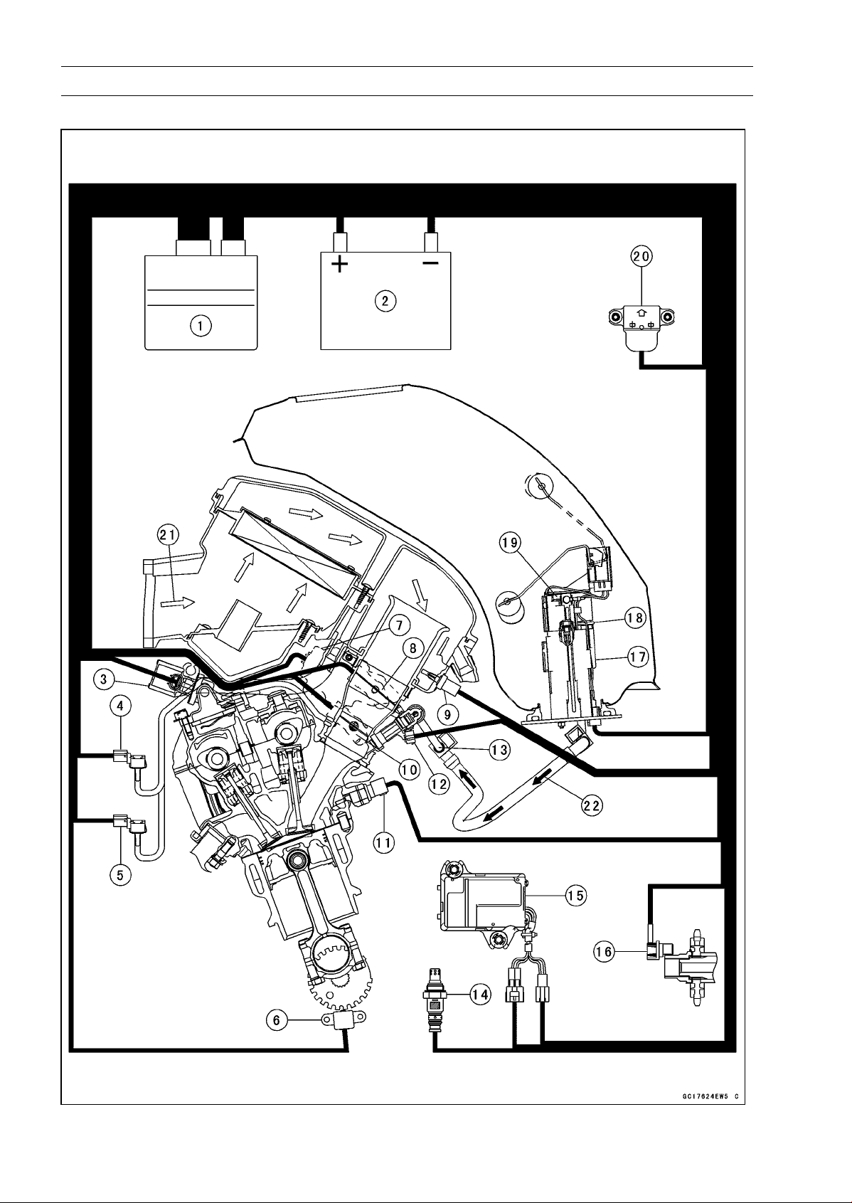
3-10 FUEL SYSTEM (DFI)
DFI System
DFI System

FUEL SYSTEM (DFI) 3-11
DFI System
1. ECU
2. Battery 12 V 8 Ah
3. Air Switching Valve
4. Intake Air Pressure Sensor #1
5. Intake Air Pressure Sensor #2
6. Crankshaft Sensor
7. Subthrottle Valve Actuator
8. Subthrottle Sensor
9. Intake Air Temperature Sensor
10. Main Throttle Sensor
11. Water Temperature Sensor
12. Fuel Injectors
13. Delivery Pipe Assy
14. Oxygen Sensor (Equipped Models)
15. Exhaust Butterfly Valve Actuator
16. Speed Sensor
17. Fuel Pump
18. Pressure Regulator
19. Fuel Filter
20. Vehicle-down Sensor
21. Air Flow
22. Fuel Flow
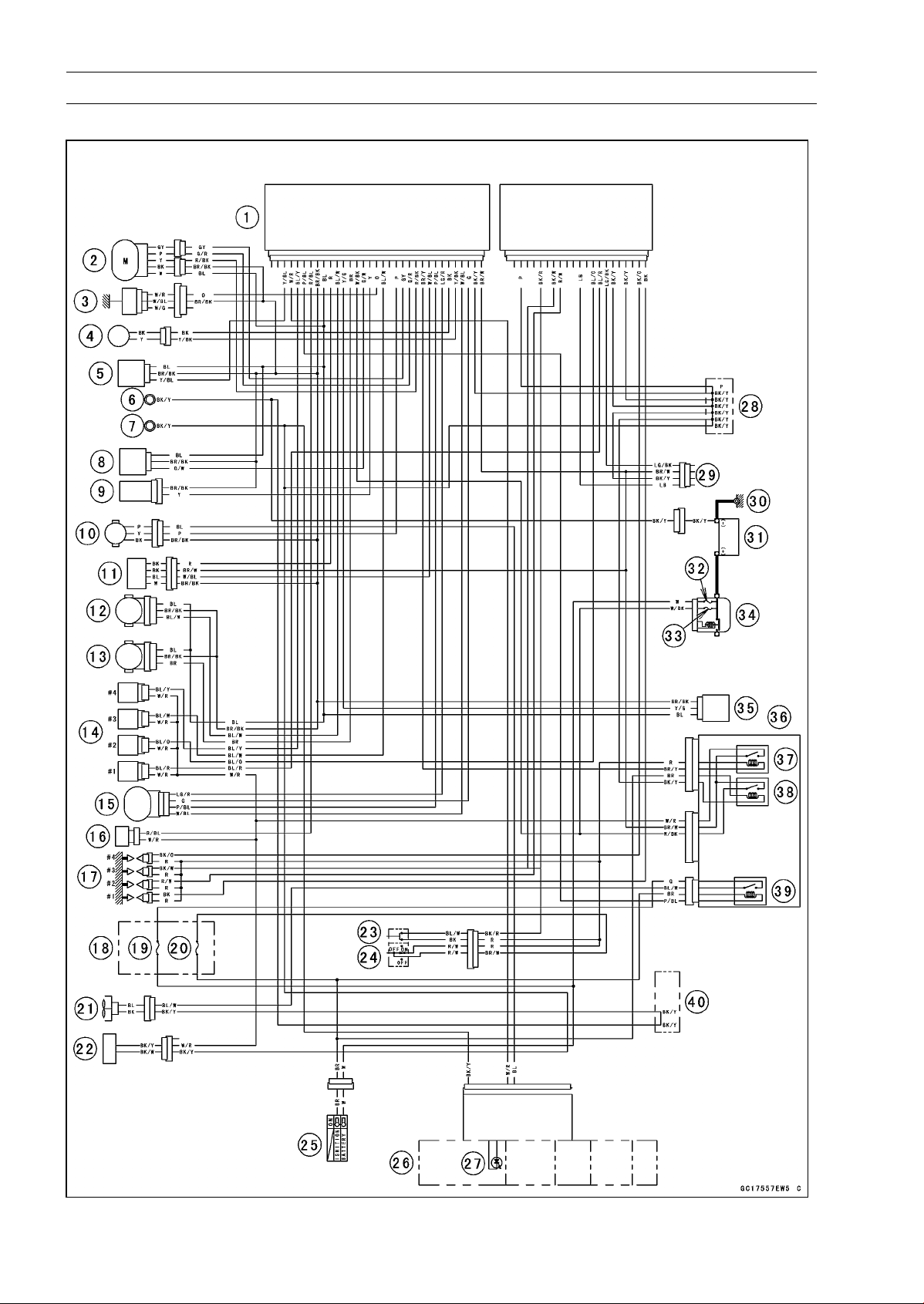
3-12 FUEL SYSTEM (DFI)
DFI System
DFI System Wiring Diagram

FUEL SYSTEM (DFI) 3-13
DFI System
Part Names
1. ECU
2. Exhaust Butterfly Valve Actuator
3. Water Temperature Sensor
4. Crankshaft Sensor
5. Intake Air Pressure Sensor #1
6. Frame Ground
7. Meter Ground
8. Intake Air Pressure Sensor #2
9. Intake Air Temperature Sensor
10. Speed Sensor
11. Oxygen Sensor
12. Main Throttle Sensor
13. Subthrottle Sensor
14. Fuel Injectors
15. Subthrottle Valve Actuator
16. Air Switching Valve
17. Stick Coils
18. Fuse Box
19. Fan Fuse 15 A
20. Ignition Fuse 15 A
21. Radiator Fan Motor
22. Fuel Pump/Fuel Level Sensor
23. Starter Button
24. Engine Stop Switch
25. Ignition Switch
26. Meter Unit
27. Oil Pressure/FI/Immobilizer Warning Indicator Light (LED)
28. Water-proof Joint C
29. Immobilizer (Equipped Models)/Kawasaki Diagnostic System Connector
30. Engine Ground
31. Battery 12 V 8 Ah
32. Main Fuse 30 A
33. FI Fuse 15 A
34. Starter Relay
35. Vehicle-down Sensor
36. Relay Box
37. Fuel Pump Relay
38. ECU Main Relay
39. Radiator Fan Relay
40. Water-proof Joint A
○
Color Codes:
BK: Black
BL: Blue
BR: Brown
CH: Chocolate
DG: Dark Green
G: Green
GY: Gray
LB: Light Blue
LG: Light Green
O: Orange
P: Pink
PU: Purple
R: Red
V: Violet
W: White
Y: Yellow
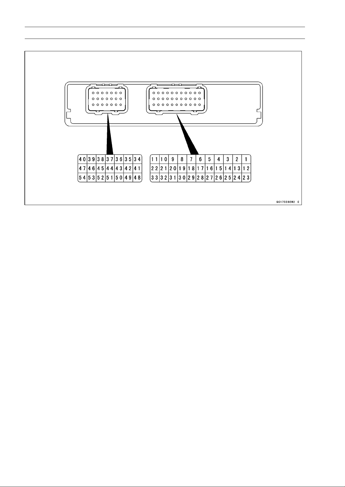
3-14 FUEL SYSTEM (DFI)
DFI System
Terminal Numbers of ECU Connectors
Terminal Names
1. Subthrottle Valve Actuator: LG/R
2. Exhaust Butterfly Valve Actuator (–): GL
3. Exhaust Butterfly Valve Actuator (+): G/R
4. Fuel Pump Relay: BR/Y
5. Power Supply to Sensors: BL
6. Power Supply to ECU (from ECU Main Relay): BR/W
7. Air Switching Valve: R/BL
8. Power Supply to ECU (from Battery): W/BK
9. Oxygen Sensor Heater (Equipped Models): R
10. Fuel Injector #4: BL/Y
11. Fuel Injector #3: BL/W
12. Subthrottle Valve Actuator: P/BL
13. Unused
14. Unused
15. Intake Air Temperature Sensor: Y
16. Intake Air Pressure Sensor #2: G/W
17. Intake Air Pressure Sensor #1: Y/BL
18. Radiator Fan Relay: P/BL
19. Vehicle-down Sensor: Y/G
20. Crankshaft Sensor (+): Y/BK
21. Crankshaft Sensor (–): BK
22. Speed Sensor: P
23. Subthrottle Valve Actuator: G
24. Subthrottle Valve Actuator: W/BL
25. Sidestand Switch: G/R
26. Main Throttle Sensor: BL/W
27. Subthrottle Sensor: BR
28. Exhaust Butterfly Valve Actuator Sensor: R/BK
29. Water Temperature Sensor: O
30. Ground for ECU: BK/Y
31. Warning Indicator Light (LED) (Meter Unit): W/R
32. Oxygen Sensor (Equipped Models): W/BL
33. Ground for Sensors: BR/BK
34. Fuel Injector #2: BL/O

FUEL SYSTEM (DFI) 3-15
DFI System
35. Starter Button: BK/R
36. Fuel Injector #1: BL/R
37. Engine Stop Switch: R
38. Stick Coil #4: BK/O
39. Stick Coil #3: BK/W
40. Stick Coil #1: BK
41. External Communication Line (Immobilizer System, Equipped Models/*KDS): LG/BK
42. Unused
43. Neutral Switch: LG
44. Starter Lockout Switch: R/G
45. Immobilizer Amplifier (Equipped Models): V
46. Unused
47. Stick Coil #2: R/W
48. Ground: P
49. Unused
50. External Communication Line (Immobilizer System, Equipped Models/*KDS): LB
51. Meter Unit (Tachometer): R/Y
52. Immobilizer Amplifier (Equipped Models): Y
53. Ground for Fuel System: BK/Y
54. Ground for Ignition System: BK/Y
*: KDS (Kawasaki Diagnostic System)
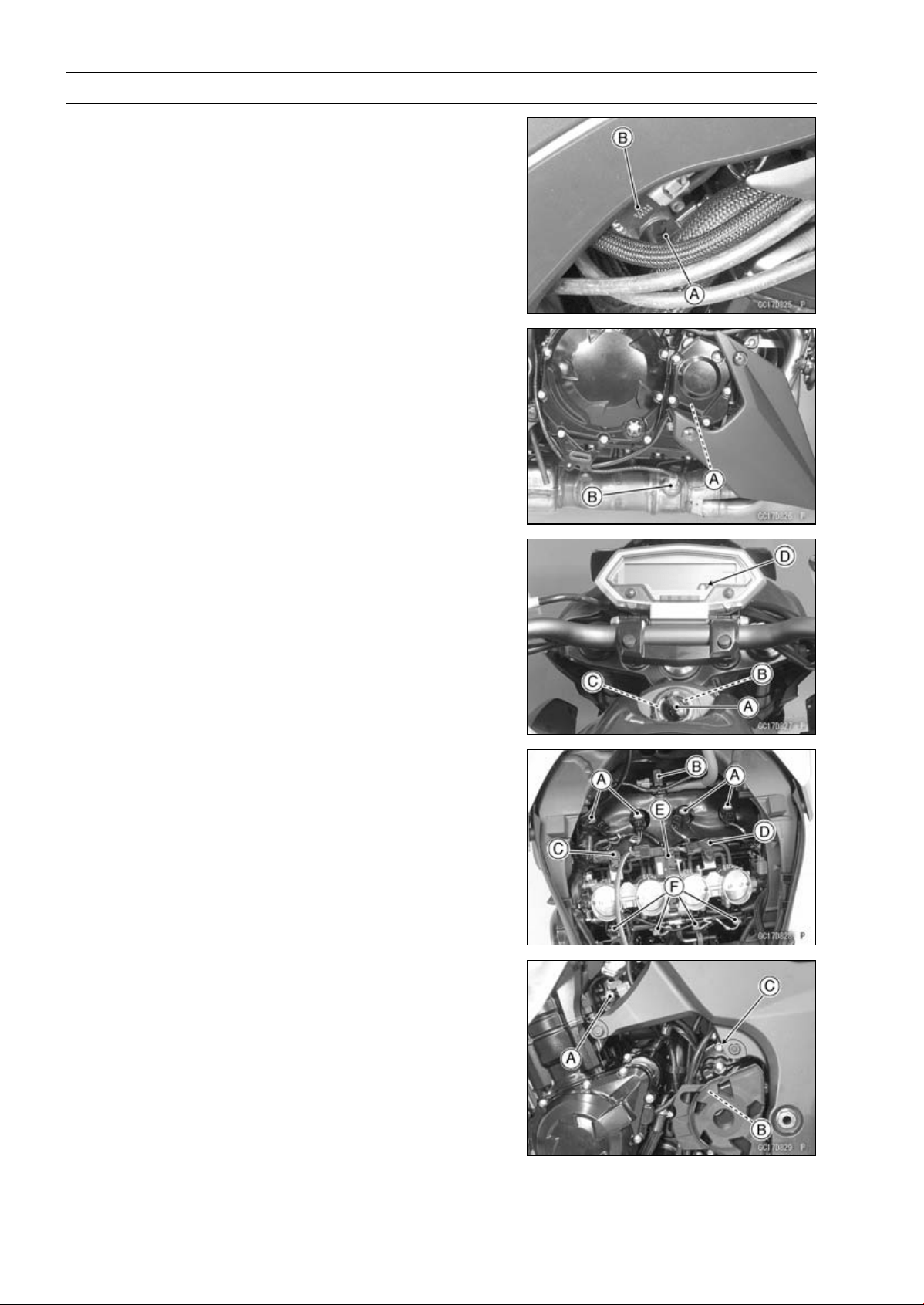
3-16 FUEL SYSTEM (DFI)
DFI Parts Location
Main Throttle Sensor [A]
Subthrottle Sensor [B]
Crankshaft Sensor [A]
Oxygen Sensor [B] (Equipped Models)
Ignition Key (Transponder, Equipped Models) [A]
Ignition Switch [B]
Immobilizer Antenna [C] (Equipped Models)
Warning Indicator Light (LED) [D]
Stick Coils [A]
Air Switching Valve [B]
Intake Air Pressure Sensor #1 [C]
Intake Air Pressure Sensor #2 [D]
Subthrottle Valve Actuator [E]
Fuel Injectors [F]
Water Temperature Sensor [A]
Speed Sensor [B]
Engine Ground [C]
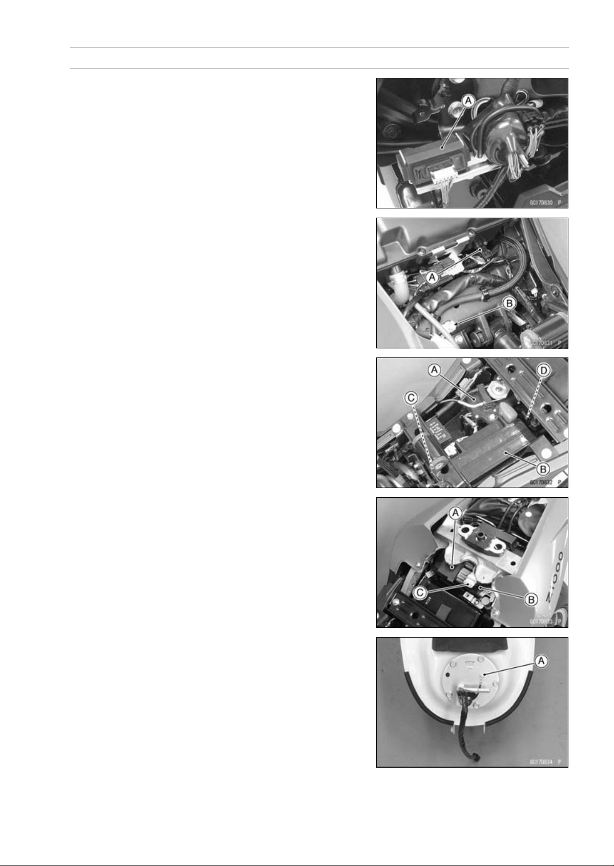
FUEL SYSTEM (DFI) 3-17
DFI Parts Location
Immobilizer Amplifier [A] (Equipped Models)
Intake Air Temperature Sensor [A]
Frame Ground [B]
Exhaust Butterfly Valve Actuator [A]
Battery 12 V 8 Ah [B]
Vehicle-down Sensor [C]
FI Fuse 15 A [D]
Relay Box (ECU Main Relay, Radiator Fan Relay, Fuel
Pump Relay) [A]
ECU [B]
Immobilizer (Equipped Models)/Kawasaki Diagnostic
System Connector [C]
Fuel Pump [A]
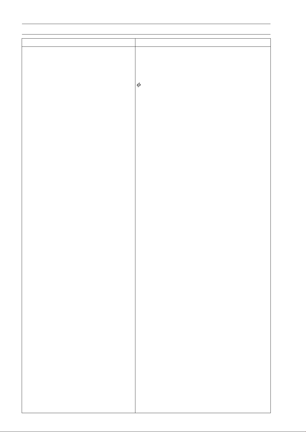
3-18 FUEL SYSTEM (DFI)
Specifications
Item Standard
Digital Fuel Injection System
Idle Speed 1 100 ±50 r/min (rpm)
Throttle Body Assy:
Throttle Valve Dual throttle valve
Bore 38 mm (1.42 in.)
Throttle Body Vacuum 40.7 ±1.3 kPa (305 ±10 mmHg)
Bypass Screws (Turn Out) 2 1/2 (for reference)
ECU:
Make DENSO
Type Digital memory type, with built in IC igniter, sealed
with resin
Fuel Pressure (High Pressure Line) 294 kPa (3.0 kgf/cm², 43 psi) with engine idling
Fuel Pump:
Type In-tank friction pump
Discharge 50 mL (1.7 US oz.) or more for 3 seconds
Fuel Injectors:
Type INP-289
Nozzle Type Fine atomizing type with 8 holes
Resistance About 11.7 ∼ 12.3 Ω at 20°C (68°F)
Main Throttle Sensor:
Input Voltage DC 4.75 ∼ 5.25 V
Output Voltage DC 1.02 ∼ 1.06 V at idle throttle opening
DC 4.22 ∼ 4.42 V at full throttle opening (for reference)
Resistance 4 ∼ 6kΩ
Intake Air Pressure Sensor #1/Intake Air
Pressure Sensor #2:
Input Voltage DC 4.75 ∼ 5.25 V
Output Voltage DC 3.80 ∼ 4.20 V at standard atmospheric pressure
(see this text for details)
Intake Air Temperature Sensor:
Output Voltage About DC 2.25 ∼ 2.50 V at 20°C (68°F)
Resistance 5.4 ∼ 6.6 kΩ at 0°C (32°F)
0.29 ∼ 0.39 kΩ at 80°C (176°F)
Water Temperature Sensor:
Output Voltage About DC 2.80 ∼ 2.97 V at 20°C (68°F)
Speed Sensor:
Input Voltage About DC 9 ∼ 11 V
Output Voltage Less than DC 0.6 V or Over than 4.8 V at ignition
switch ON and 0 km/h
Vehicle-down Sensor:
Input Voltage DC 4.75 ∼ 5.25 V
Output Voltage With sensor tilted 60 ∼ 70° or more right or left: DC
0.65 ∼ 1.35 V
With sensor arrow mark pointed up: DC 3.55 ∼ 4.45 V

FUEL SYSTEM (DFI) 3-19
Specifications
Item Standard
Subthrottle Sensor:
Input Voltage DC 4.75 ∼ 5.25 V
Output Voltage DC 1.08 ∼ 1.12 V at subthrottle valve full close
position
DC 4.2 ∼ 4.4 V at subthrottle valve full open position
(for reference)
Resistance 4 ∼ 6kΩ
Exhaust Butterfly Valve Actuator Sensor:
Input Voltage DC 4.75 ∼ 5.25 V
Output Voltage DC 3.46 ∼ 3.76 V at pulley original position
Resistance
4 ∼ 6kΩ
Immobilizer Antenna (Equipped Models):
Resistance About 3.0 ∼ 4.6 Ω
Exhaust Butterfly Valve Actuator:
Resistance 5 ∼ 200 Ω (for reference)
Subthrottle Valve Actuator:
Resistance
About 5.2 ∼ 7.8 Ω
Input Voltage About DC 11.5 ∼ 13.5 V
Oxygen Sensor (Equipped Models):
Output Voltage (Rich) DC 0.7 V or more
Output Voltage (Lean) DC 0.2 V or less
Heater Resistance
11.7 ∼ 14.5 Ω at 20°C (68°F)
Throttle Grip and Cables
ThrottleGripFreePlay 2 ∼ 3mm(0.08∼ 0.12 in.)
Air Cleaner
Element Viscous paper element
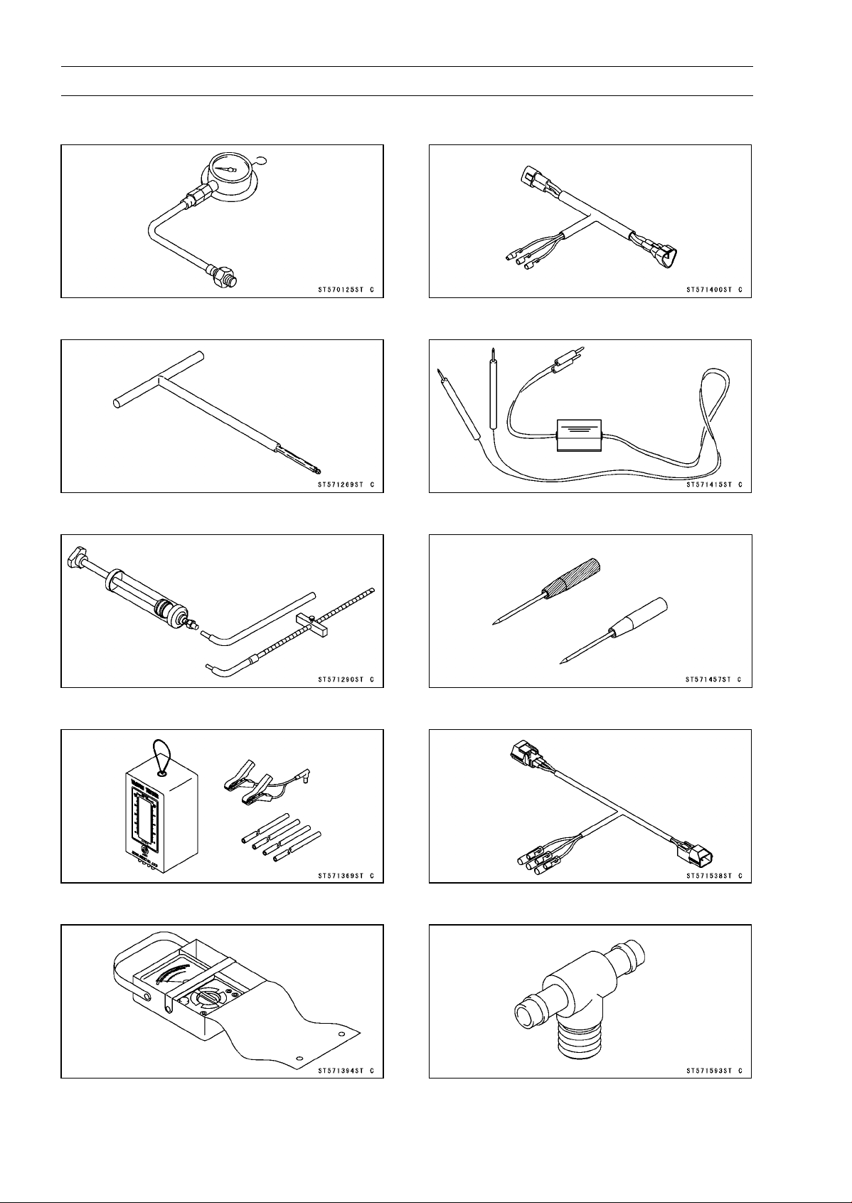
3-20 FUEL SYSTEM (DFI)
Special Tools and Sealant
Oil Pressure Gauge, 5 kgf/cm²:
57001-125
Carburetor Drain Plug Wrench, Hex 3:
57001-1269
Fork Oil Level Gauge:
57001-1290
Vacuum Gauge:
57001-1369
Hand Tester:
57001-1394
Throttle Sensor Setting Adapter #1:
57001-1400
Peak Voltage Adapter:
57001-1415
Needle Adapter Set:
57001-1457
Throttle Sensor Setting Adapter:
57001-1538
Fuel Pressure Gauge Adapter:
57001-1593
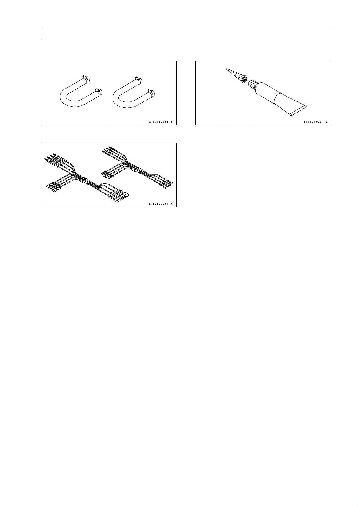
FUEL SYSTEM (DFI) 3-21
Special Tools and Sealant
Fuel Hose:
57001-1607
Measuring Adapter:
57001-1700
Liquid Gasket, TB1211:
56019-120
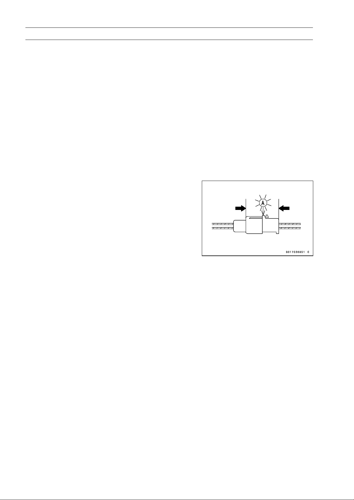
3-22 FUEL SYSTEM (DFI)
DFI Servicing Precautions
DFI Servicing Precautions
There are a number of important precautions that should
be followed servicing the DFI system.
○
This DFI system is designed to be used with a 12 V sealed
battery as its power source. Do not use any other battery
except for a 12 V sealed battery as a power source.
○
Do not reverse the battery cable connections. This will
damage the ECU.
○
To prevent damage to the DFI parts, do not disconnect the
battery cables or any other electrical connections when
the ignition switch is ON, or while the engine is running.
○
Take care not to short the leads that are directly con-
nected to the battery positive (+) terminal to the chassis
ground.
○
When charging, remove the battery from the motorcycle.
This is to prevent ECU damage by excessive voltage.
○
Whenever the DFI electrical connections are to be dis-
connected, first turn off the ignition switch, and disconnect
the battery (–) terminal. Do not pull the lead, only the con-
nector. Conversely, make sure that all the DFI electrical
connections are firmly reconnected before starting the en-
gine.
○
Connect these connectors until they click [A].
○
Do not turn the ignition switch ON while any of the DFI
electrical connectors are disconnected. The ECU memo-
rizes service codes.
○
Do not spray water on the electrical parts, DFI parts, con-
nectors, leads and wiring.
○
If a transceiver is installed on the motorcycle, make sure
that the operation of the DFI system is not influenced by
electric wave radiated from the antenna. Check operation
of the system with the engine at idle. Locate the antenna
as far as possible away from the ECU.
○
When any fuel hose is disconnected, do not turn on the
ignition switch. Otherwise, the fuel pump will operate and
fuel will spout from the fuel hose.
○
Do not operate the fuel pump if the pump is completely
dry. This is to prevent pump seizure.
○
Before removing the fuel system parts, blow the outer sur-
faces of these parts clean with compressed air.
○
When any fuel hose is disconnected, fuel may spout out
by residual pressure in the fuel line. Cover the hose joint
with a piece of clean cloth to prevent fuel spillage.
○
When installing the fuel hoses, avoid sharp bending, kink-
ing, flattening or twisting, and run the fuel hoses with a
minimum of bending so that the fuel flow will not be ob-
structed.
○
Run the hoses according to Cable, Wire, and Hose Rout-
ing section in the Appendix chapter.
○
To prevent corrosion and deposits in the fuel system, do
not add to fuel any fuel antifreeze chemicals.
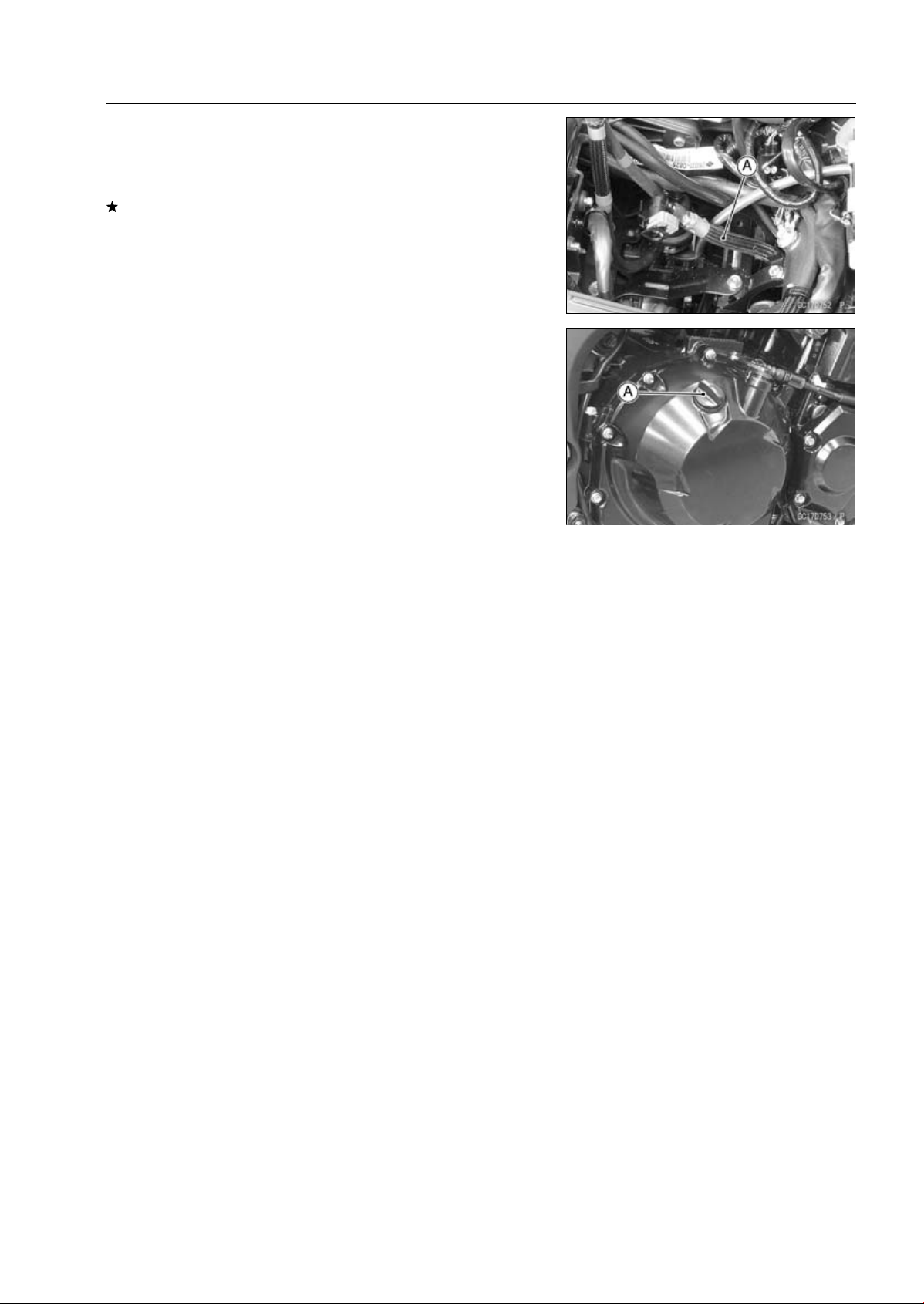
FUEL SYSTEM (DFI) 3-23
DFI Servicing Precautions
○
If the motorcycle is not properly handled, the high pres-
sure inside the fuel line can cause fuel to leak or the hose
to burst. Remove the fuel tank (see Fuel Tank Removal)
and check the fuel hose [A].
Replace the fuel hose if any fraying, cracks or bulges are
noticed.
○
To maintain the correct fuel/air mixture (F/A), there must
be no intake air leaks in the DFI system. Be sure to install
the oil filler plug [A] after filling the engine oil.
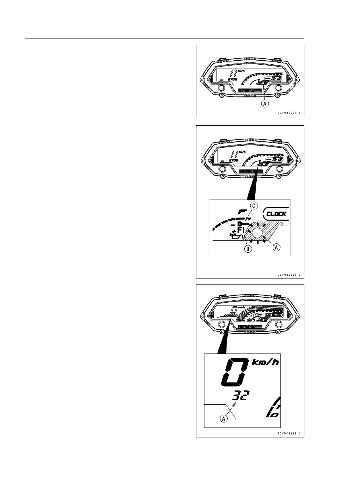
3-24 FUEL SYSTEM (DFI)
Troubleshooting the DFI System
The warning indicator light (LED) [A] is used for the FI
indicator, immobilizer indicator (equipped models) and oil
pressure warning indicator.
Outline
When a problem occurs with DFI system, the warning in-
dicator light (LED) [A] and FI warning symbol [B] blinks to
alert the rider. In addition, the condition of the problem is
stored in the memory of the ECU. For models equipped with
an immobilizer system, the warning indicator light (LED)
and immobilizer warning symbol [C] blinks, when a prob-
lem occurs in the system.
With the engine stopped and turned in the self-diagnosis
mode, the service code [A] is displayed on the LCD (Liquid
Crystal Display) by the number of two digits.
If the problem is with the following parts, the ECU can not
recognize these problem. Therefore, the warning indicator
light (LED), FI and/or immobilizer warning symbols do not
blinks, and service code is not displayed.
LCD for Meter Unit
Fuel Pump
Fuel Pump Relay
Fuel Injectors
Stick Coil Secondary Wiring and Ground Wiring
ECU Main Relay
ECU Power Source Wiring and Ground Wiring
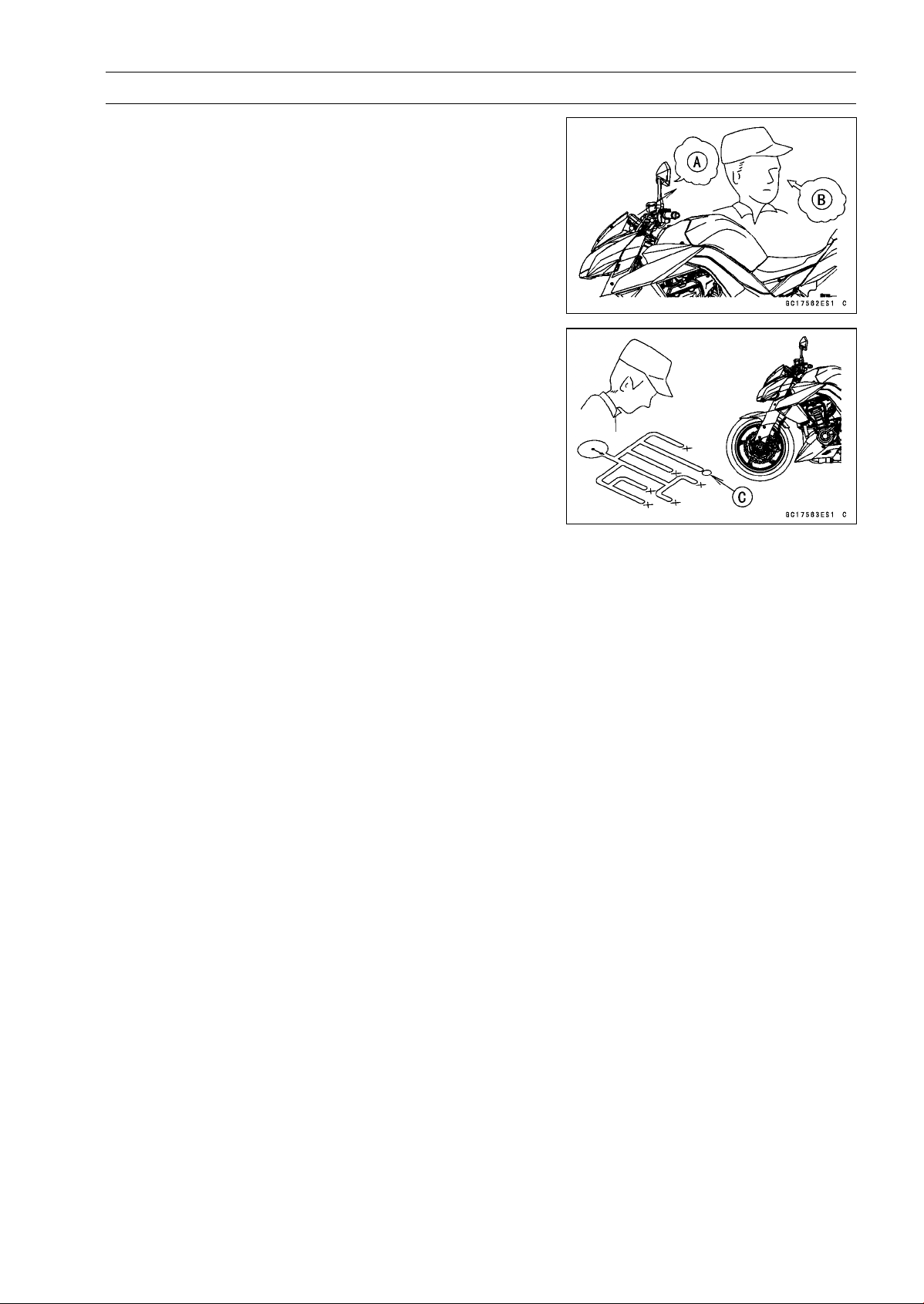
FUEL SYSTEM (DFI) 3-25
Troubleshooting the DFI System
When the service code [A] is displayed, for first ask the
rider about the conditions [B] of trouble, and then start to
determine the cause [C] of problem.
As a pre-diagnosis inspection, check the ECU for ground
and power supply, the fuel line for no fuel leaks, and for
correct pressure. The pre-diagnosis items are not indicated
by the warning indicator light (LED) and FI warning symbol.
Don’t rely solely on the DFI self-diagnosis function, use
common sense.
Even when the DFI system is operating normally, the
warning indicator light (LED) and FI warning symbol may
blink under strong electrical interference. Additional mea-
sures are not required. Turn the ignition switch OFF to stop
the indicator light and symbol.
If the warning indicator light (LED) and FI warning symbol
of the motorcycle brought in for repair still blinks, check the
service code.
When the repair has been done, the FI warning symbol
goes off. But the service codes stored in memory of the
ECU are not erased to preserve the problem history. The
problem history can be referred using the KDS (Kawasaki
Diagnostic System) when solving unstable problems.
When the motorcycle is down, the vehicle-down sensor
operates and the ECU shuts off the fuel pump relay, fuel in-
jectors and ignition system. The ignition switch is left ON. If
the starter button is pushed, the electric starter turns but the
engine does not start. When the starter button is pushed,
the warning indicator light (LED) and FI warning symbol
blink but the service code is not displayed. To start the
engine again, raise the motorcycle, turn the ignition switch
OFF, and then ON.
Much of the DFI system troubleshooting work consists
of confirming continuity of the wiring. The DFI parts are
assembled and adjusted with precision, and it is impossible
to disassemble or repair them.
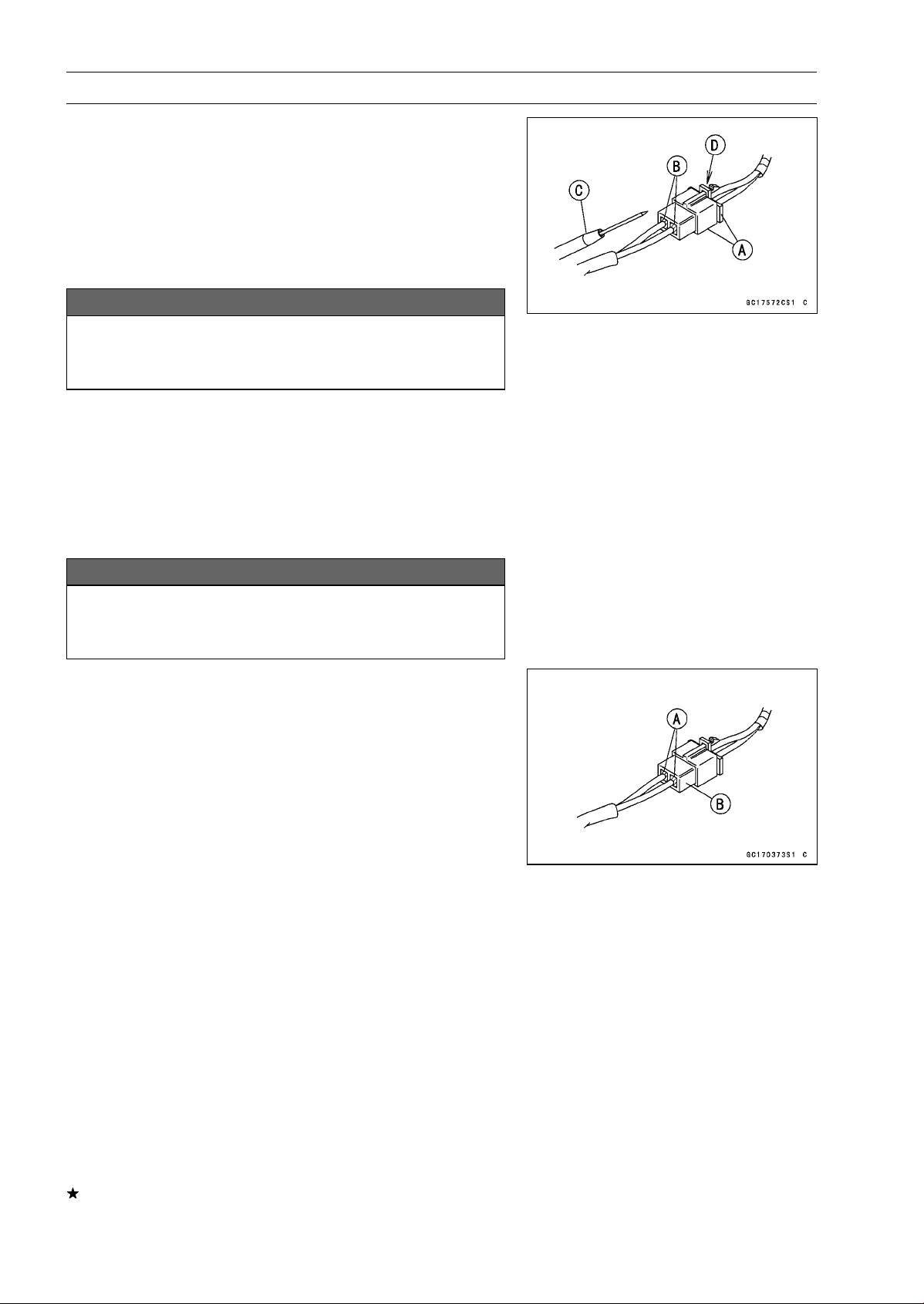
3-26 FUEL SYSTEM (DFI)
Troubleshooting the DFI System
•
When checking the DFI parts, use a digital meter which
can be read two decimal place voltage or resistance.
○
The DFI part connectors [A] have seals [B], including the
ECU. When measuring the input or output voltage with the
connector joined, use the needle adapter set [C]. Insert
the needle adapter inside the seal until the needle adapter
reaches the terminal.
Special Tool - Needle Adapter Set: 57001-1457
NOTICE
Insert the needle adapter straight along the terminal
in the connector to prevent short-circuit between
terminals.
•
Make sure that measuring points are correct in the con-
nector, noting the position of the lock [D] and the lead
color before measurement. Do not reverse connections
of a digital meter.
•
Be careful not to short-circuit the leads of the DFI or elec-
trical system parts by contact between adapters.
•
Turn the ignition switch ON and measure the voltage with
the connector joined.
NOTICE
Incorrect, reverse connection or short circuit by
needle adapters could damage the DFI or electrical
system parts.
○
After measurement, remove the needle adapters and ap-
ply silicone sealant to the seals [A] of the connector [B]
for waterproofing.
Sealant - Liquid Gasket, TB1211: 56019-120
•
Always check battery condition before replacing the DFI
parts. A fully charged battery is a must for conducting
accurate tests of the DFI system.
•
Trouble may involve one or in some cases all items.
Never replace a defective part without determining what
CAUSED the problem. If the problem was caused by
some other item or items, they too must be repaired or
replaced, or the new replacement part will soon fail again.
•
Measure coil winding resistance when the DFI part is cold
(at room temperature).
•
Make sure all connectors in the circuit are clean and tight,
and examine leads for signs of burning, fraying, short,
etc. Deteriorated leads and bad connections can cause
reappearance of problems and unstable operation of the
DFI system.
If any wiring is deteriorated, replace the wiring.
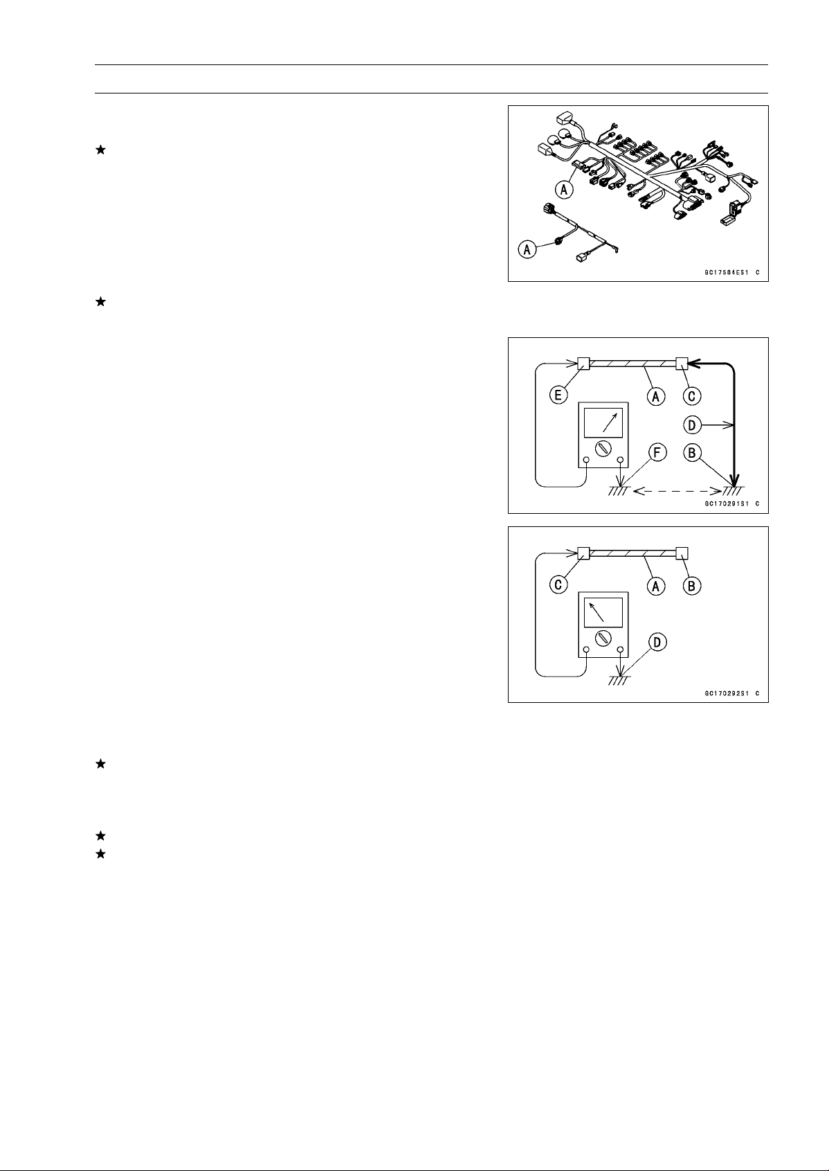
FUEL SYSTEM (DFI) 3-27
Troubleshooting the DFI System
•
Pull each connector [A] apart and inspect it for corrosion,
dirt, and damage.
If the connector is corroded or dirty, clean it carefully. If it
is damaged, replace it. Connect the connectors securely.
•
Check the wiring for continuity.
○
Use the wiring diagram to find the ends of the lead which
is suspected of being a problem.
○
Connect the hand tester between the ends of the leads.
Special Tool - Hand Tester: 57001-1394
○
Set the tester to the × 1 Ω range, and read the tester.
If the tester does not read 0 Ω, the lead is defective. Re-
place the lead or the main harness or the subharness.
○
If both ends of a harness [A] are far apart, ground [B] the
one end [C], using a jumper lead [D] and check the con-
tinuity between the end [E] and the ground [F]. This en-
ables to check a long harness for continuity. If the harness
is open, repair or replace the harness.
○
When checking a harness [A] for short circuit, open one
end [B] and check the continuity between the other end
[C] and ground [D]. If there is continuity, the harness has
a short circuit to ground, and it must be repaired or re-
placed.
•
Narrow down suspicious locations by repeating the con-
tinuity tests from the ECU connectors.
If no abnormality is found in the wiring or connectors, the
DFI parts are the next likely suspects. Check the part,
starting with input and output voltages. However, there is
no way to check the ECU itself.
If an abnormality is found, replace the affected DFI part.
If no abnormality is found in the wiring, connectors, and
DFI parts, replace the ECU.
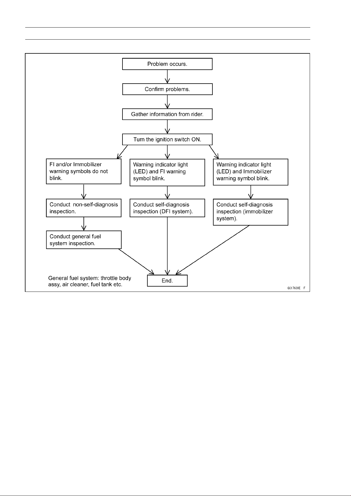
3-28 FUEL SYSTEM (DFI)
Troubleshooting the DFI System
DFI Diagnosis Flow Chart
Inquiries to Rider
○
Each rider reacts to problems in different ways, so it is important to confirm what kind of symptoms
the rider has encountered.
○
Try to find out exactly what problem occurred under exactly what conditions by asking the rider;
knowing this information may help you reproduce the problem.
○
The following sample diagnosis sheet will help prevent you from overlooking any areas, and will
help you decide if it is a DFI system problem, or a general engine problem.
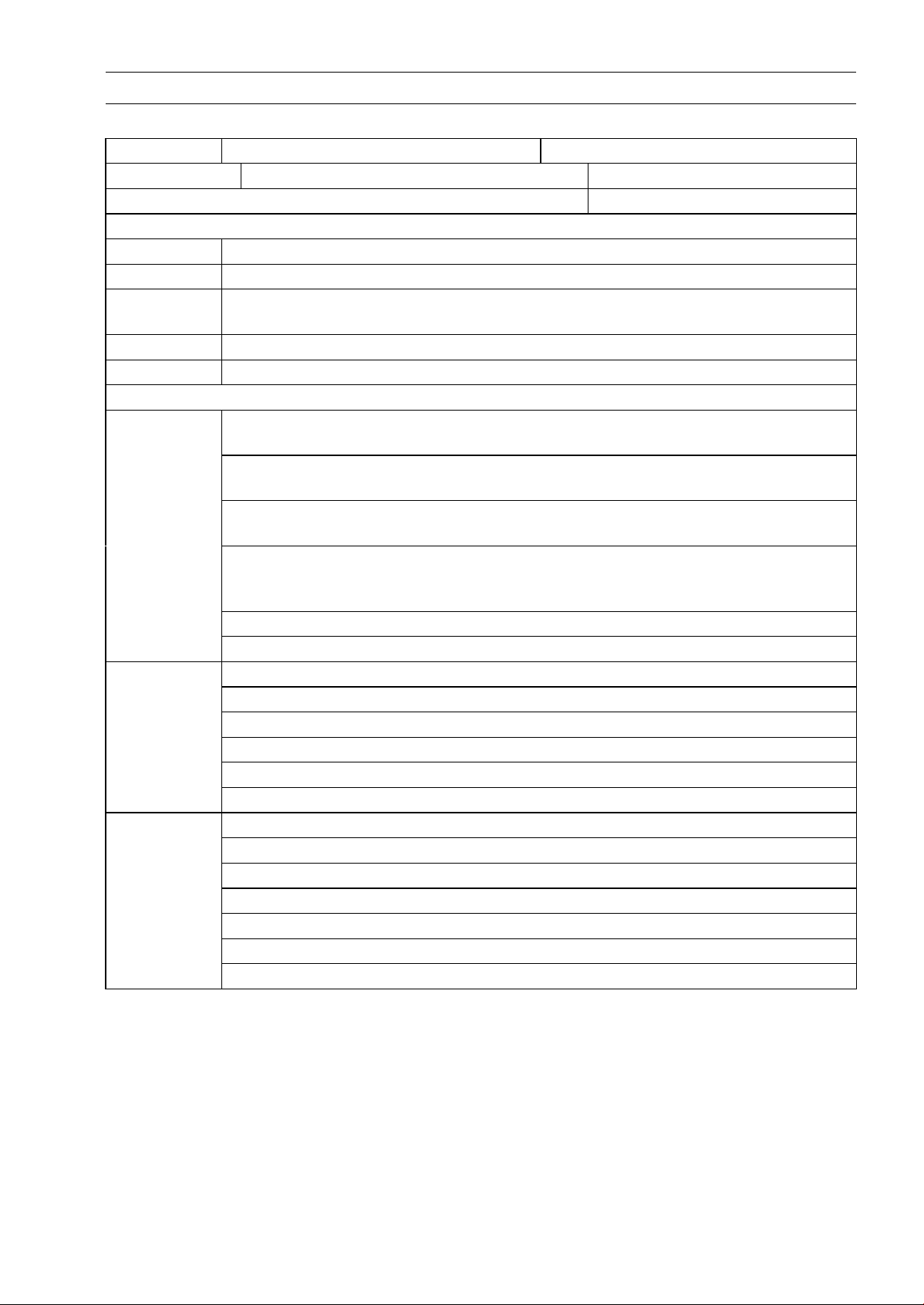
FUEL SYSTEM (DFI) 3-29
Troubleshooting the DFI System
Sample Diagnosis Sheet
Rider name:
Registration No. (license plate No.): Year of initial registration:
Model: Engine No.: Frame No.:
Date problem occurred: Mileage:
Environment when problem occurred.
Weather □ fine, □ cloudy, □ rain, □ snow, □ always, □ other:
Temperature □ hot, □ warm, □ cold, □ very cold, □ always, □ other:
Problem
frequency
□
chronic, □ often, □once
Road □ street, □ highway, □ mountain road (□ uphill, □ downhill), □ bumpy, □ pebble
Altitude □ normal, □ high (about 1 000 m or more)
Motorcycle conditions when problem occurred.
□ Starts blinking about 3 seconds after from ignition switch ON, and goes off after
engine pressure becomes high enough (with engine running).
□
Starts blinking about 3 seconds after from ignition switch ON, and the FI warning
symbol on the LCD starts blinking (DFI system problem).
□
Starts blinking about 3 seconds after from ignition switch ON, and the immobilizer
warning symbol on the LCD starts blinking (immobilizer system problem).
□
Starts blinking about 3 seconds after from ignition switch ON, and about
10 seconds after, the FI warning symbol on the LCD starts blinking (ECU
communication error).
□ Does not blink about 3 seconds after ignition switch ON.
Warning
indicator light
(LED)
□ light up (ECU or meter unit replace).
□ starter motor not rotating.
□ starter motor rotating but engine do not turn over.
□ starter motor and engine do not turn over.
□ no fuel flow (□ no fuel in tank, □ no fuel pump sound).
□ no spark.
Starting
difficulty
□ other:
□ right after starting.
□ when opening throttle grip.
□ when closing throttle grip.
□ when moving off.
□ when stopping the motorcycle.
□ when cruising.
Engine stalls
□ other:

3-30 FUEL SYSTEM (DFI)
Troubleshooting the DFI System
□ very low idle speed, □ very high idle speed, □ rough idle speed.
□ battery voltage is low (charge the battery).
□ spark plug loose (tighten it).
□ spark plug dirty, broken, or gap maladjusted (remedy it).
□
backfiring.
□ afterfiring.
□ hesitation when acceleration.
□ engine oil viscosity too high.
□ brake dragging.
□ engine overheating.
□ clutch slipping.
Poor running
at low speed
□ other:
□ spark plug loose (tighten it).
□ spark plug dirty, broken, or gap maladjusted (remedy it).
□ spark plug incorrect (replace it).
□ knocking (fuel poor quality or incorrect, → use high-octane gasoline).
□ brake dragging.
□ clutch slipping.
□ engine overheating.
□ engine oil level too high.
□ engine oil viscosity too high.
Poor running
or no power at
high speed
□ other:
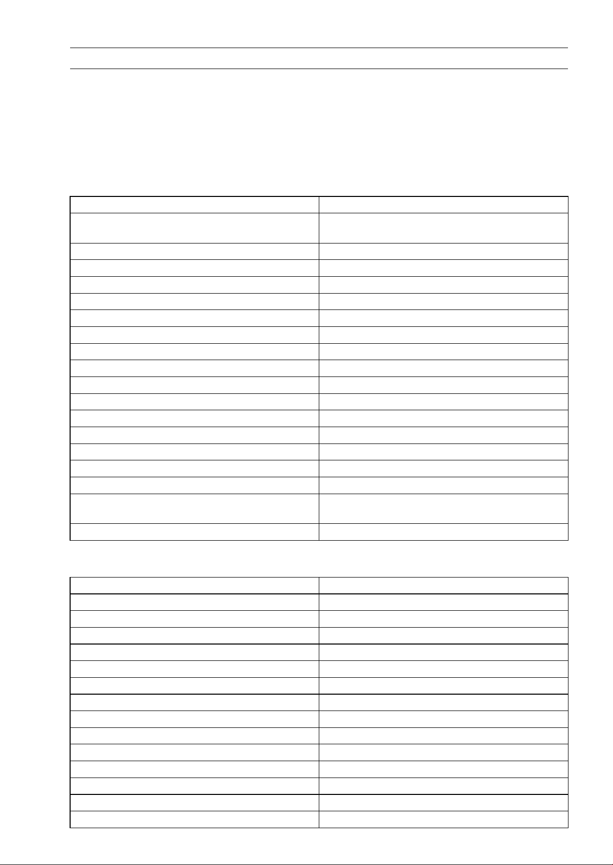
FUEL SYSTEM (DFI) 3-31
DFI System Troubleshooting Guide
NOTE
○
This is not an exhaustive list, giving every possible cause for each problem listed. It is meant
simply as a rough guide to assist the troubleshooting for some of the more common difficulties in
DFI system.
○
The ECU may be involved in the DFI electrical and ignition system troubles. If these parts and
circuits are checked out good, be sure to check the ECU for ground and power supply. If the
ground and power supply are checked good, replace the ECU.
Engine Won’t Turn Over
Symptoms or Possible Causes Actions (chapter)
Neutral, starter lockout or sidestand switch
trouble
Inspect each switch (see chapter 16).
Immobilizer system trouble
Inspect (see chapter 3).
Vehicle-down sensor operated
Turn ignition switch OFF (see chapter 3).
Vehicle-down sensor trouble Inspect (see chapter 3).
Crankshaft sensor trouble Inspect (see chapter 16).
Stick coil shorted or not in good contact Inspect or Reinstall (see chapter 16).
Stick coil trouble Inspect (see chapter 16).
Spark plug dirty, broken or gap maladjusted Inspect and replace (see chapter 2).
Spark plug incorrect Replace it with the correct plug (see chapter 2).
ECU ground and power supply trouble Inspect (see chapter 3).
ECU trouble Inspect (see chapter 3).
No or little fuel in tank Supply fuel (see Owner’s Manual).
Fuel injector trouble Inspect and replace (see chapter 3).
Fuel pump not operating
Inspect (see chapter 3).
Fuel pump relay trouble
Inspect and replace (see chapter 16).
Fuel filter or pump screen clogged Inspect and replace fuel pump (see chapter 3).
Fuel pressure regulator trouble Inspect fuel pressure and replace fuel pump (see
chapter 3).
Fuel line clogged Inspect and repair (see chapter 3).
Poor Running at Low Speed
Symptoms or Possible Causes Actions (chapter)
Spark weak:
Stick coil shorted or not in good contact Inspect or reinstall (see chapter 16).
Stick coil trouble Inspect (see chapter 16).
Spark plug dirty, broken or gap maladjusted Inspect and replace (see chapter 2).
Spark plug incorrect Replace it with the correct plug (see chapter 2).
ECU trouble Inspect (see chapter 3).
Fuel/air mixture incorrect:
Little fuel in tank Supply fuel (see Owner’s Manual).
Air cleaner clogged, poorly sealed, or missing
Clean element or inspect sealing (see chapter 2).
Air duct loose Reinstall (see chapter 3).
Throttle body assy holder loose Reinstall (see chapter 3).
Throttle body assy dust seal damage Replace (see chapter 3).
Fuel injector O-ring damage Replace (see chapter 3).
Fuel filter or pump screen clogged Inspect and replace fuel pump (see chapter 3).

3-32 FUEL SYSTEM (DFI)
DFI System Troubleshooting Guide
Symptoms or Possible Causes Actions (chapter)
Fuel pressure regulator trouble
Inspect fuel pressure and replace fuel pump (see
chapter 3).
Fuel line clogged Inspect and repair (see chapter 3).
Intake air pressure sensor #1 trouble Inspect (see chapter 3).
Intake air pressure sensor #2 trouble Inspect (see chapter 3).
Water temperature sensor trouble Inspect (see chapter 3).
Intake air temperature sensor trouble Inspect (see chapter 3).
Main throttle sensor trouble Inspect (see chapter 3).
Subthrottle sensor trouble Inspect (see chapter 3).
Subthrottle valve actuator trouble Inspect (see chapter 3).
Unstable (rough) idling:
Fuel pressure too low or too high Inspect (see chapter 3).
Fuel injector trouble Inspect (see chapter 3).
Main throttle sensor trouble Inspect (see chapter 3).
Subthrottle sensor trouble Inspect (see chapter 3).
Subthrottle valve actuator trouble Inspect (see chapter 3).
Engine vacuum no
t synchronizing
Inspect and adjust (see chapter 2).
Intake air pressure sensor #1 trouble Inspect (see chapter 3).
Intake air pressure sensor #2 trouble Inspect (see chapter 3).
Water temperature sensor trouble Inspect (see chapter 3).
Intake air temperature sensor trouble Inspect (see chapter 3).
Engine stalls easily:
Spark plug dirty, broken or gap maladjusted Inspect and replace (see chapter 2).
Stick coil trouble Inspect (see chapter 16).
Main throttle sensor trouble
Inspect (see chapter 3).
Subthrottle sensor trouble Inspect (see chapter 3).
Subthrottle valve actuator trouble Inspect (see chapter 3).
Intake air pressure sensor #1 trouble Inspect (see chapter 3).
Intake air pressure sensor #2 trouble Inspect (see chapter 3).
Water temperature sensor trouble Inspect (see chapter 3).
Intake air temperature sensor trouble
Inspect (see chapter 3).
Fuel pump trouble
Inspect (see chapter 3).
Fuel injector trouble Inspect (see chapter 3).
Fuel pressure too low or too high Inspect (see chapter 3).
Fuel pressure regulator trouble Inspect fuel pressure and replace fuel pump (see
chapter 3).
Fuel line clogged Inspect and repair (see chapter 3).
Poor acceleration:
Fuel pressure too low Inspect (see chapter 3).
Water or foreign matter in fuel Change fuel. Inspect and clean fuel system (see
chapter 3).
Fuel filter or pump screen clogged Inspect and replace fuel pump (see chapter 3).
Fuel pump trouble Inspect (see chapter 3).
Fuel injector trouble Inspect (see chapter 3).
Main throttle sensor trouble Inspect (see chapter 3).

FUEL SYSTEM (DFI) 3-33
DFI System Troubleshooting Guide
Symptoms or Possible Causes Actions (chapter)
Subthrottle sensor trouble Inspect (see chapter 3).
Subthrottle valve actuator trouble Inspect (see chapter 3).
Intake air pressure sensor #1 trouble Inspect (see chapter 3).
Intake air pressure sensor #2 trouble Inspect (see chapter 3).
Water temperature sensor trouble
Inspect (see chapter 3).
Intake air temperature sensor trouble Inspect (see chapter 3).
Spark plug dirty, broken or gap maladjusted Inspect and replace (see chapter 2).
Stick coil trouble Inspect (see chapter 16).
Stumble:
Fuel pressure too low
Inspect (see chapter 3).
Fuel injector trouble
Inspect (see chapter 3).
Main throttle sensor trouble Inspect (see chapter 3).
Subthrottle sensor trouble Inspect (see chapter 3).
Subthrottle valve actuator trouble Inspect (see chapter 3).
Intake air pressure sensor #1 trouble Inspect (see chapter 3).
Intake air pressure sensor #2 trouble Inspect (see chapter 3).
Water temperature sensor trouble
Inspect (see chapter 3).
Intake air temperature sensor trouble Inspect (see chapter 3).
Surge:
Unstable fuel pressure Fuel pressure regulator trouble (Inspect and
replace fuel pump) or kinked fuel line (Inspect
and replace fuel pump) (see chapter 3).
Fuel injector trouble
Inspect (see chapter 3).
Water temperature sensor trouble Inspect (see chapter 3).
Backfiring when deceleration:
Spark plug dirty, broken or gap maladjusted Inspect and replace (see chapter 2).
Fuel pressure too low Inspect (see chapter 3).
Fuel pump trouble
Inspect (see chapter 3).
Main throttle sensor trouble
Inspect (see chapter 3).
Subthrottle sensor trouble Inspect (see chapter 3).
Subthrottle valve actuator trouble Inspect (see chapter 3).
Intake air pressure sensor #1 trouble Inspect (see chapter 3).
Intake air pressure sensor #2 trouble Inspect (see chapter 3).
Water temperature sensor trouble
Inspect (see chapter 3).
Intake air temperature sensor trouble
Inspect (see chapter 3).
Air switching valve trouble Inspect and replace (see chapter 16).
Air suction valve trouble Inspect and replace (see chapter 5).
After fire:
Spark plug burned or gap maladjusted Replace (see chapter 2).
Fuel injector trouble
Inspect (see chapter 3).
Intake air pressure sensor #1 trouble Inspect (see chapter 3).
Intake air pressure sensor #2 trouble Inspect (see chapter 3).
Water temperature sensor trouble Inspect (see chapter 3).
Intake air temperature sensor trouble Inspect (see chapter 3).

3-34 FUEL SYSTEM (DFI)
DFI System Troubleshooting Guide
Symptoms or Possible Causes Actions (chapter)
Other:
Intermittent any DFI fault and its recovery Check that DFI connectors are clean and tight,
and examine leads for signs of burning or fraying
(see chapter 3).
Poor Running or No Power at High Speed
Symptoms or Possible Causes Actions (chapter)
Firing incorrect:
Stick coil shorted or not in good contact Inspect or Reinstall (see chapter 16).
Stick coil trouble Inspect (see chapter 16).
Spark plug dirty, broken or gap maladjusted Inspect and replace (see chapter 2).
Spark plug incorrect Replace it with the correct plug (see chapter 2).
ECU trouble Inspect (see chapter 3).
Fuel/air mixture incorrect:
Air cleaner clogged, poorly sealed, or missing Clean element or inspect sealing (see chapter 2).
Air duct loose
Reinstall (see chapter 3).
Throttle body assy holder loose
Reinstall (see chapter 3).
Throttle body assy dust seal damage Replace (see chapter 3).
Water or foreign matter in fuel Change fuel. Inspect and clean fuel system (see
chapter 3).
Fuel injector O-ring damage Replace (see chapter 3).
Fuel injector clogged Inspect and repair (see chapter 3).
Fuel line clogged Inspect and repair (see chapter 3).
Fuel pump operates intermittently and often DFI
fuse blows.
Fuel pump bearings may wear. Replace the fuel
pump (see chapter 3).
Fuel pump trouble Inspect (see chapter 3).
Intake air pressure sensor #1 trouble Inspect (see chapter 3).
Intake air pressure sensor #2 trouble Inspect (see chapter 3).
Cracked or obstructed intake air pressure sensor
hose
Inspect and repair or replace (see chapter 3).
Water temperature sensor trouble
Inspect (see chapter 3).
Intake air temperature sensor trouble
Inspect (see chapter 3).
Main throttle sensor trouble Inspect (see chapter 3).
Subthrottle sensor trouble Inspect (see chapter 3).
Subthrottle valve actuator trouble Inspect (see chapter 3).
Knocking:
Fuel poor quality or incorrect Fuel change (Use the gasoline recommended in
the Owner’s Manual).
Spark plug incorrect Replace it with the correct plug (see chapter 2).
Stick coil trouble Inspect (see chapter 16).
ECU trouble Inspect (see chapter 3).
Engine vacuum not synchronizing Inspect and adjust (see chapter 2).
Intake air pressure sensor #1 trouble Inspect (see chapter 3).
Intake air pressure sensor #2 trouble Inspect (see chapter 3).
Water temperature sensor trouble Inspect (see chapter 3).

FUEL SYSTEM (DFI) 3-35
DFI System Troubleshooting Guide
Symptoms or Possible Causes Actions (chapter)
Intake air temperature sensor trouble Inspect (see chapter 3).
Miscellaneous:
Subthrottle sensor trouble Inspect (see chapter 3).
Subthrottle valve actuator trouble Inspect (see chapter 3).
Speed sensor trouble Inspect (see chapter 3).
Throttle valves will not fully open Inspect throttle cables and lever linkage (see
chapter 3).
Engine overheating - Water temperature sensor,
crankshaft sensor or speed sensor trouble
(see Overheating of Troubleshooting Guide in
chapter 17)
Air switching valve trouble Inspect and replace (see chapter 16).
Air suction valve trouble Inspect and replace (see chapter 5).
Exhaust Smokes Excessively:
(Black smoke)
Air cleaner element clogged
Clean element (see chapter 2).
Fuel pressure too high Inspect (see chapter 3).
Fuel injector trouble Inspect (see chapter 3).
Water temperature sensor trouble Inspect (see chapter 3).
Intake air temperature sensor trouble Inspect (see chapter 3).
(Brown smoke)
Air duct loose
Reinstall (see chapter 3).
Fuel pressure too low Inspect (see chapter 3).
Water temperature sensor trouble Inspect (see chapter 3).
Intake air temperature sensor trouble Inspect (see chapter 3).
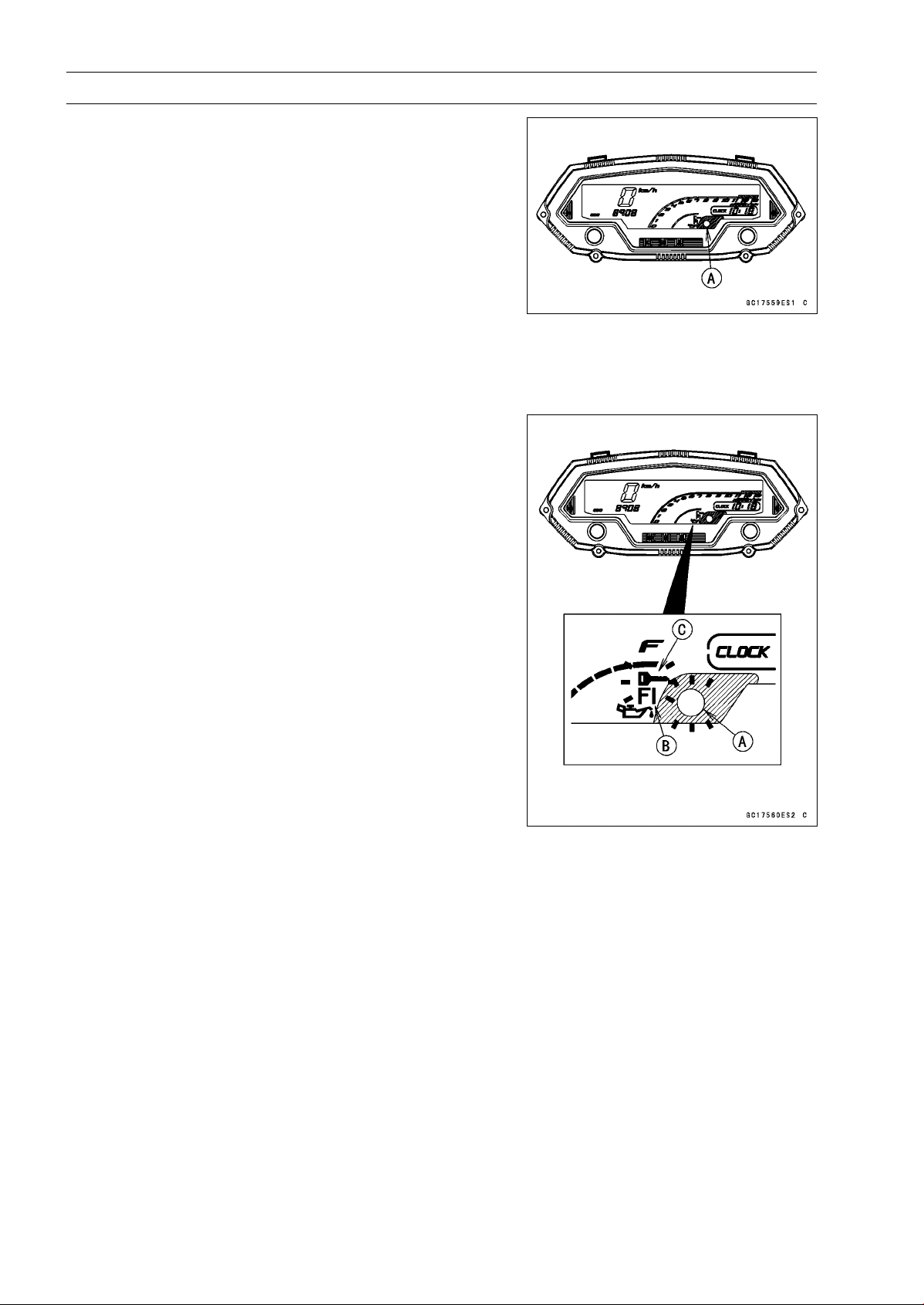
3-36 FUEL SYSTEM (DFI)
Self-Diagnosis
The warning indicator light (LED) [A] is used for the FI
indicator, immobilizer indicator (equipped models) and oil
pressure warning indicator.
Self-diagnosis Outline
The self-diagnosis system has two modes and can be
switched to another mode by operating the meter unit.
User Mode
The ECU notifies the rider of troubles in DFI system, igni-
tion system and immobilizer system by blinking the warning
indicator light (LED) [A], FI warning symbol [B] and immobi-
lizer warning symbol [C] when DFI, ignition and immobilizer
system parts are faulty, and initiates fail-safe function. In
case of serious troubles ECU stops the injection and igni-
tion operations.
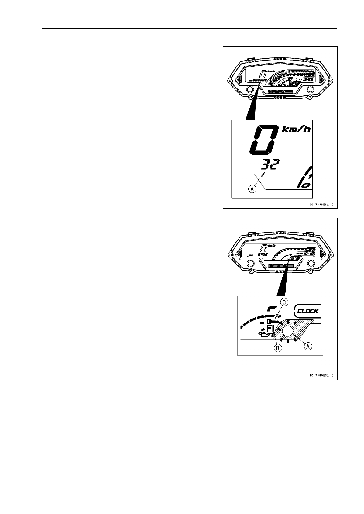
FUEL SYSTEM (DFI) 3-37
Self-Diagnosis
Dealer Mode
The LCD (Liquid Crystal Display) display the service
code(s) [A] to show the problem(s) which the DFI system,
ignition system and immobilizer system has at the moment
of diagnosis.
Self-diagnosis Procedures
○
When a problem occurs with the DFI system and ignition
system, the warning indicator light (LED) [A] and FI warn-
ing symbol [B] blink.
○
For models equipped with an immobilizer system, when
a problem occurs with the system, the warning indicator
light (LED) and immobilizer warning symbol [C] blink.
NOTE
○
Use a fully charged battery when conducting
self-diagnosis. Otherwise, the light (LED) and symbol
blink very slowly or do not blink.
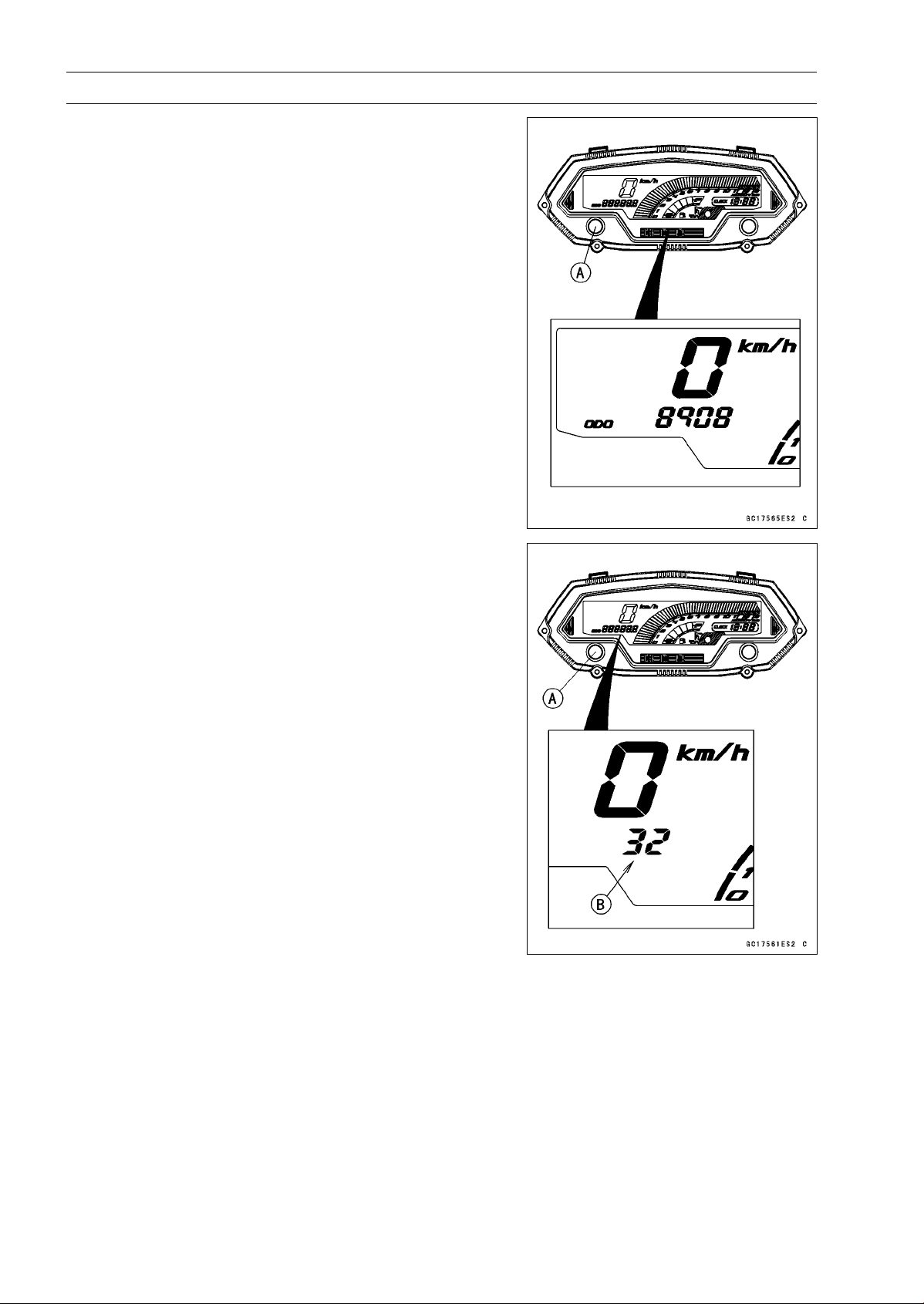
3-38 FUEL SYSTEM (DFI)
Self-Diagnosis
•
Turn the ignition switch ON.
•
Push the left button [A] to display the odometer.
•
Push the left button [A] for more than two seconds.
•
The service code [B] is displayed on the LCD by the num-
ber of two digits.
•
Any of the following procedures ends self-diagnosis.
○
When the service code is displayed on the LCD, push the
left button for more than two seconds.
○
When the ignition switch is turned OFF.
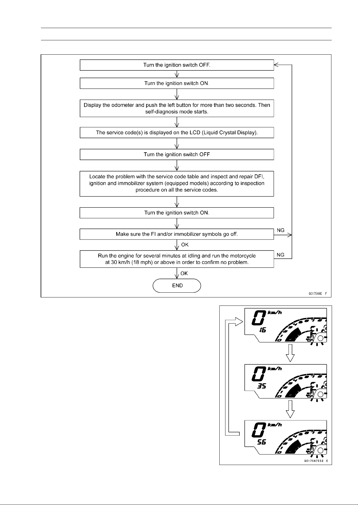
FUEL SYSTEM (DFI) 3-39
Self-Diagnosis
Self-Diagnosis Flow Chart
Service Code Reading
○
The service code(s) is displayed on the LCD by the num-
ber of two digits.
○
When there are a number of problems, all the service
codes can be stored and the display will begin starting
from the lowest number service code in the numerical or-
der.
○
Then after completing all codes, the display is repeated
until the ignition switch is turned OFF or left button is
pushed for more than two seconds.
○
For example, if three problems occurred in the order of
56, 16, 35, the service codes are displayed (each two sec-
onds) from the lowest number in the order listed as shown
below. (16→35→56)→(16→35→56)→· · ·(repeated)
○
If there is no problem or when the repair has been done,
FI and/or immobilizer symbols go off and service code is
not displayed.

3-40 FUEL SYSTEM (DFI)
Self-Diagnosis
ServiceCodeErasing
○
When repair has been done, FI and/or immobilizer warning symbols go off and service code is not
displayed.
But the service codes stored in memory of the ECU are not erased to preserve the problem history.
In this model, the problem history can not be erased.
Service Code Table
Service Code Problems
11 Main throttle sensor malfunction, wiring open or short
12
Intake air pressure sensor #1 malfunction, wiring open or short
13 Intake air temperature sensor malfunction, wiring open or short
14 Water temperature sensor malfunction, wiring open or short
16 Intake air pressure sensor #2 malfunction, wiring open or short
21 Crankshaft sensor malfunction, wiring open or short
24
and
25
Speed sensor malfu
nction, wiring open or short
First 24 is displayed and then 25, repeatedly
31 Vehicle-down sensor malfunction, wiring open or short
32
Subthrottle sensor malfunction, wiring open or short
33 Oxygen sensor inactivation, wiring open or short (Equipped Models)
34 Exhaust butterfly valve actuator sensor malfunction, wiring open or short
35 Immobilizer amplifier malfunction (Equipped Models)
36 Blank Key detection (Equipped Models)
39 ECU communication error
51
Stick coil #1 malfunction, wiring open or short
52 Stick coil #2 malfunction, wiring open or short
53 Stick coil #3 malfunction, wiring open or short
54 Stick coil #4 malfunction, wiring open or short
56 Radiator fan relay malfunction, wiring open or short
62 Subthrottle valve actuator malfunction, wiring open or short
63
Exhaust butterfly valve actuator malfunction, wiring open or short
64
Air switching valve malfunction, wiring open or short
67
Oxygen sensor heater malfunction, wiring open or short (Equipped Models)
94 Oxygen sensor malfunction, wiring open or short (Equipped Models)
Notes:
○
The ECU may be involved in these problems. If all the parts and circuits checked out good, be sure
to check the ECU for ground and power supply. If the ground and power supply are checked good,
replace the ECU.
○
When no service code is displayed, the electrical parts of the DFI system has no fault, and the
mechanical parts of the DFI system and the engine are suspect.

FUEL SYSTEM (DFI) 3-41
Self-Diagnosis
Backups
○
The ECU takes the following measures to prevent engine damage when the DFI, ignition or immo-
bilizer system parts have troubles.
Service
Codes
Parts
Output Signal Usable
Range or Criteria
Backups by ECU
11
Main Throttle
Sensor
Output Voltage
0.2 ∼ 4.8 V
If the main throttle sensor system fails (the
output voltage is out of the usable range,
wiring short or open), the ECU locks ignition
timing into the ignition timing at closed throttle
position and sets the DFI in the D-J method (1).
12
Intake Air
Pressure
Sensor #1
Intake Air Pressure
(Absolute)
Pv = 100 ∼ 900 mmHg
If the intake air pressure sensor #1 system
fails (the signal is out of the usable range,
wiring short or open), the ECU sets the DFI
in the α-N method (2).
13
Intake Air
Temperature
Sensor
Intake Air Temperature
Ta = – 47 ∼ + 178°C
If the intake air temperature sensor system
fails (the signal is out of the usable range,
wiring short or open), the ECU sets Ta at 40°C.
14
Water
Temperature
Sensor
Water Temperature
Tw = – 30 ∼ + 120°C
If the water temperature sensor system fails
(the signal is out of the usable range, wiring
short or open), the ECU sets Tw at 80°C and
radiator fan operates.
16
Intake Air
Pressure
Sensor #2
Atmospheric Pressure
(Absolute)
Pa = 100 ∼ 900 mmHg
If the intake air pressure sensor #2 system
fails (the signal is out of the usable range,
wiring short or open), the ECU sets Pa at 760
mmHg (the standard atmospheric pressure).
21
Crankshaft
Sensor
Crankshaft sensor must
send 22 signals to the ECU
at the 1 cranking.
If the crankshaft sensor generates less than
22 or more signals, the engine stops by itself.
24
and
25
Speed
Sensor
Speed sensor must send
23 signals to the ECU at
the one rotation of the drive
shaft.
The gear position is
decided by the signal of the
speed sensor.
If the speed sensor system fails (no signal,
wiring short or open), the speedometer shows
0.
31
Vehicle
-down
Sensor
Output Voltage
0.10 ∼ 4.84 V
If the vehicle-down sensor system has failures
(the output voltage is out of the usable range,
wiring short or open), the ECU shuts off the
fuel pump relay, the fuel injectors and the
ignition system.
32
Subthrottle
Sensor
Output Voltage
0.15 ∼ 4.85 V
If the subthrottle sensor system fails (the
output voltage is out of the usable range, wiring
short or open), the ECU drive the subthrottle
valve to the full closed position, and it stops
the current to the subthrottle valve actuator.
33
Oxygen
Sensor
(Equipped
Models)
The oxygen sensor is
active and sensor must
send signals (output
voltage) continuously to
the ECU.
If the oxygen sensor is not activated, the ECU
stops the feedback mode of the oxygen sensor.

3-42 FUEL SYSTEM (DFI)
Self-Diagnosis
Service
Codes
Parts
Output Signal Usable
Range or Criteria
Backups by ECU
34
Exhaust
Butterfly
Valve
Actuator
Sensor
Output Voltage
0.1 ∼ 4.8 V
If the exhaust butterfly valve sensor system
fails (the output voltage is out of the usable
range, wiring short or open), the ECU locks
the exhaust butterfly valve at full open position
near, and it stops the current to the exhaust
butterfly valve actuator.
35
Immobilizer
Amplifier
(Equipped
Models)
–
If the immobilizer system fails (no signal, wiring
short or open), the vehicle is no start and run.
36
Master or
User Key*
(Equipped
Models)
The user or master key
must use register key.
If the blank key or broken key is used, the
vehicleisnostart
and run.
39 ECU
The ECU send the data
(for service code and key
registration) to the meter
unit.
–
51
Stick Coil
#1**
The stick coil primary
winding must send
signals (output voltage)
continuously to the ECU.
If the stick coil #1 primary winding has failures
(no signal, wiring short or open), the ECU
shuts off the injector #1 to stop fuel to the
cylinder #1, though the engine keeps running.
52
Stick Coil
#2**
The stick coil primary
winding must send
signals (outp
ut voltage)
continuously to the ECU.
If the stick coil #2 primary winding has failures
(no signal, wiring short or open), the ECU
shuts off the injector #2 to stop fuel to the
cylinder #2, though the engine keeps running.
53
Stick Coil
#3**
The stick coil primary
winding must send
signals (output voltage)
continuously to the ECU.
If the stick coil #3 primary winding has failures
(no signal, wiring short or open), the ECU
shuts off the injector #3 to stop fuel to the
cylinder #3, though the engine keeps running.
54
Stick Coil
#4**
The stick co
il primary
winding must send
signals (output voltage)
continuou
sly to the ECU.
If the stick coil #4 primary winding has failures
(no signal, wiring short or open), the ECU
shuts off the injector #4 to stop fuel to the
cylinder #4, though the engine keeps running.
56
Radiator Fan
Relay
When the relay OFF
condition, the fan relay is
open.
–
62
Subthrottle
Valve
Actuator
The actuator operates
open and close of the
subthro
ttle valve by the
pulse signal from the ECU.
If the subthrottle valve actuator fails (the
signal is out to the usable range, wiring short
or open), the ECU stops the current to the
actuator.
63
Exhaust
Butterfly
Valve
Actuator
The actuator operates
open and close of the
exhaust butterfly valve by
the pulse signal from the
ECU.
If the exhaust butterfly valve actuator fails (the
signal is out to the usable range, wiring short
or open), the ECU stops the current to the
actuator.
64
Air Switching
Valve
The air switching valve
controls the flow of the
secondary air by opening
and shutting the solenoid
valve.
–

FUEL SYSTEM (DFI) 3-43
Self-Diagnosis
Service
Codes
Parts
Output Signal Usable
Range or Criteria
Backups by ECU
67
Oxygen
Sensor
Heater
(Equipped
Models)
The oxygen sensor heater
raise temperature of
the sensor for its earlier
activation.
If the oxygen sensor heater fails (wiring short
or open), the ECU stops the current to the
heater, and it stops the feedback mode of the
oxygen sensor.
94
Oxygen
Sensor
(Equipped
Models)
The oxygen sensor must
send signals (output
voltage) continuously to
the ECU
If the oxygen sensor output voltage is incorrect,
the ECU stops the feedback mode of the
oxygen sensor.
Note:
(1) D-J Method: the DFI control method from medium to heavy engine load. When the engine
load is light like at idling or low speed, the ECU determines the injection quantity by calculating from
the throttle vacuum (intake air pressure sensor output voltage) and engine speed (crankshaft sensor
output voltage). This method is called D-J method. (2) α-N Method: As the engine speed increases,
and the engine load turns middle to heavy, the ECU determines the injection quantity by calculating
from the throttle opening (main throttle sensor output voltage) and the engine speed. This method is
called α-N method.
*: The master key exists in ZR1000DA/EA only.
**: This depends on the number of stopped cylinders.
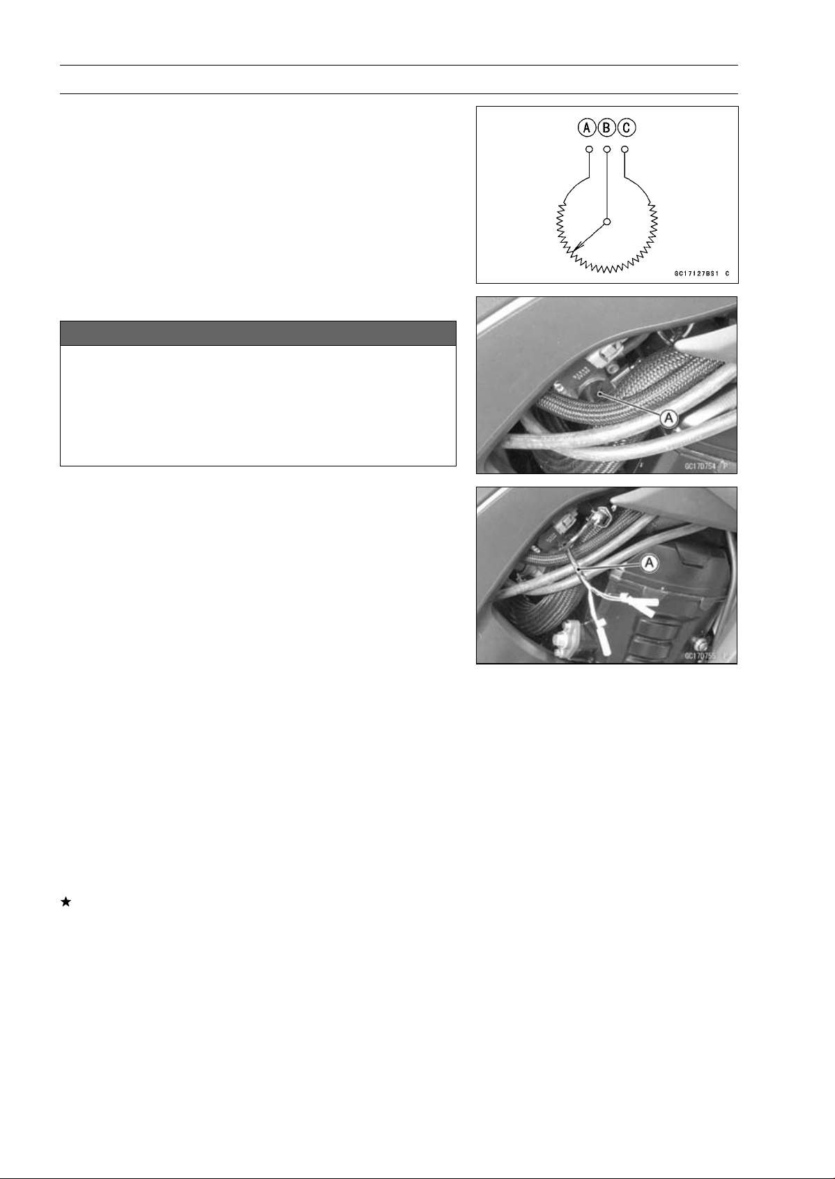
3-44 FUEL SYSTEM (DFI)
Main Throttle Sensor (Service Code 11)
The main throttle sensor is a rotating variable resistor that
change output voltage according to throttle operating. The
ECU senses this voltage change and determines fuel injec-
tion quantity, and ignition timing according to engine rpm,
and throttle opening.
Input Terminal [A]
Output Terminal [B]
Ground Terminal [C]
Main Throttle Sensor Removal/Adjustment
NOTICE
Do not remove or adjust the main throttle sensor [A]
since it has been adjusted and set with precision at
the factory.
Never drop the throttle body assy especially on a
hard surface. Such a shock to the main throttle sen-
sor can damage it.
Main Throttle Sensor Input Voltage Inspection
NOTE
○
Be sure the battery is fully charged.
•
Turn the ignition switch OFF.
•
Disconnect the main throttle sensor connector and con-
nect the harness adapter [A] between these connectors.
Special Tool - Throttle Sensor Setting Adapter: 57001
-1538
•
Connect a digital meter to the harness adapter leads.
Main Throttle Sensor Input Voltage
Connections to Adapter:
Digital Meter (+) W (sensor BL) lead
Digital Meter (–) BK (sensor BR/BK) lead
•
Measure the input voltage with the engine stopped and
with the connector joined.
•
Turn the ignition switch ON.
Input Voltage
Standard: DC 4.75
∼ 5.25 V
•
Turn the ignition switch OFF.
If the reading is within the standard, check the output volt-
age (see Main Throttle Sensor Output Voltage Inspec-
tion).
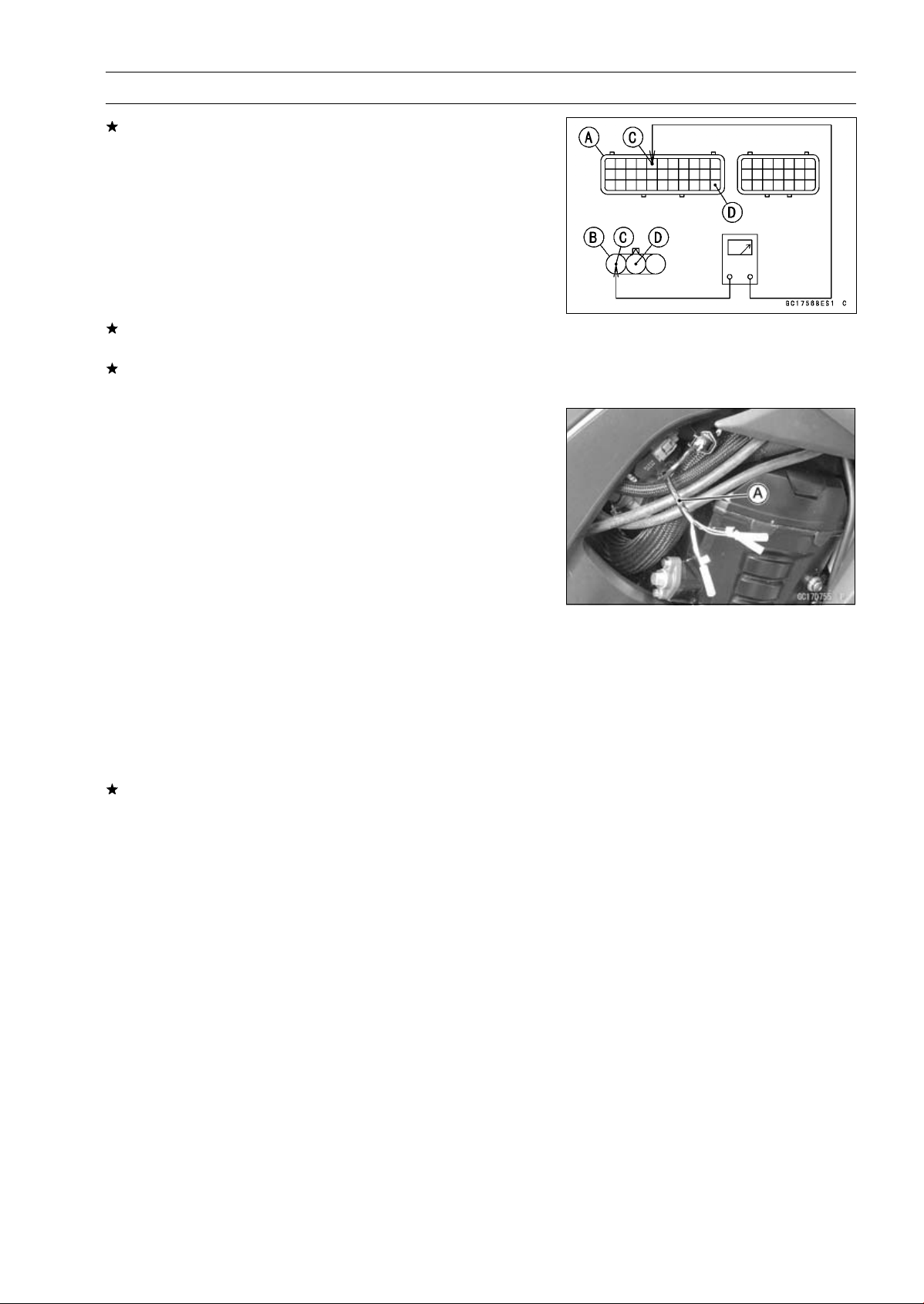
FUEL SYSTEM (DFI) 3-45
Main Throttle Sensor (Service Code 11)
If the reading is out of the standard, remove the ECU
and check the wiring for continuity between main harness
connectors.
○
Disconnect the ECU and sensor connectors.
Wiring Inspection
ECU Connector [A]
Main Throttle Sensor Connector [B]
BL lead (ECU terminal 5) [C]
BR/BK lead (ECU terminal 33) [D]
If the wiring is good, check the ECU for its ground and
power supply (see ECU Power Supply Inspection).
If the ground and power supply are good, replace the ECU
(see ECU Removal/Installation).
Main Throttle Sensor Output Voltage Inspection
•
Measure the output voltage at the main throttle sensor in
the same way as input voltage inspection, note the follow-
ing.
○
Disconnect the main throttle sensor connector and con-
nect the harness adapter [A] between these connectors.
Special Tool - Throttle Sensor Setting Adapter: 57001
-1538
Main Throttle Sensor Output Voltage
Connections to Adapter:
Digital Meter (+) R (sensor BL/W) lead
Digital Meter (–) BK (sensor BR/BK) lead
•
Start the engine and warm it up thoroughly.
•
Check idle speed to ensure the throttle opening is correct.
Idle Speed
Standard: 1 100 ±50 r/min (rpm)
If the idle speed is out of the specified range, adjust it
(see Idle Speed Inspection in the Periodic Maintenance
chapter).
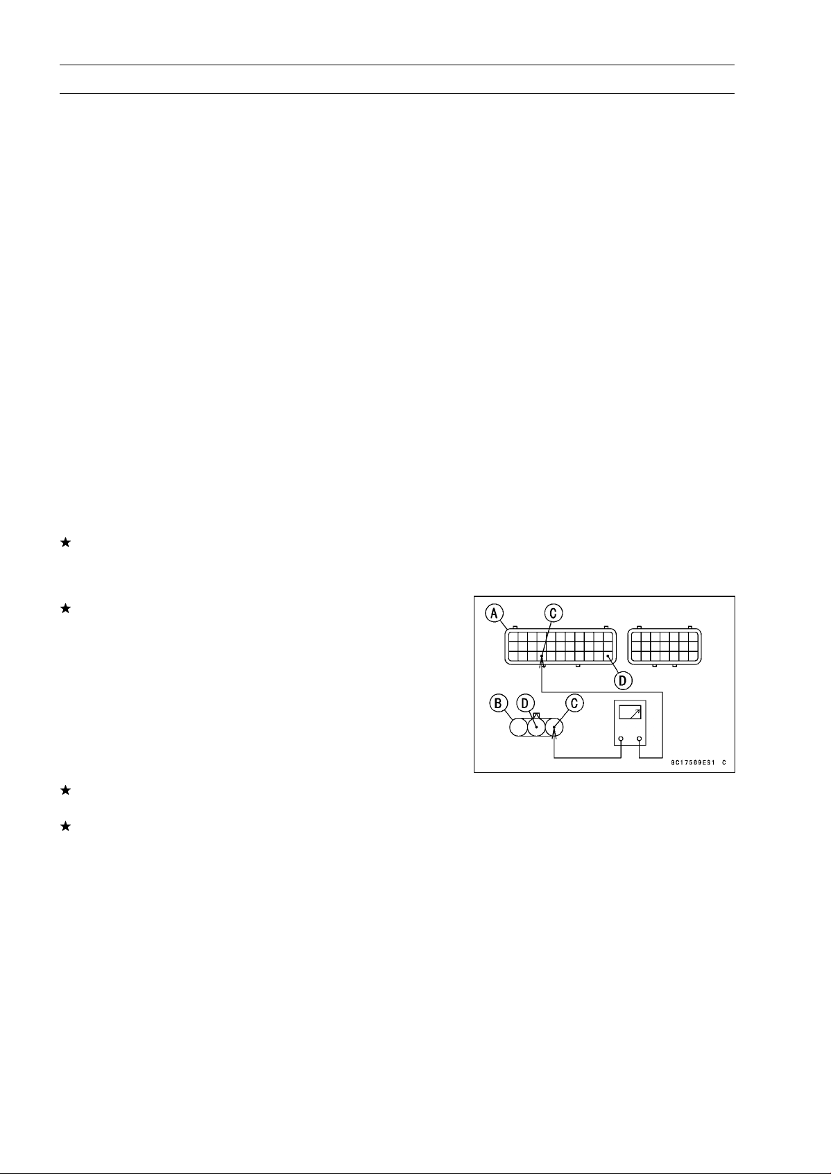
3-46 FUEL SYSTEM (DFI)
Main Throttle Sensor (Service Code 11)
•
Turn the ignition switch OFF.
•
Measure the output voltage with the engine stopped and
with the connector joined.
•
Turn the ignition switch ON.
Output Voltage
Standard: DC 1.02
∼ 1.06 V at idle throttle opening
DC 4.22
∼ 4.42 V at full throttle opening (for
reference)
NOTE
○
Open the throttle, confirm the output voltage will be
raise.
○
The standard voltage refers to the value when the volt-
age reading at the Input Voltage Inspection shows 5 V
exactly.
○
When the input voltage reading shows other than 5 V,
derive a voltage range as follows.
Example:
In the case of a input voltage of 4.75 V.
1.02 × 4.75 ÷ 5.00 = 0.969 V
1.06 × 4.75 ÷ 5.00 = 1.007 V
Thus, the valid range is 0.969
∼
1.007 V
•
Turn the ignition switch OFF.
If the reading is out of the standard, check the main throt-
tle sensor resistance (see Main Throttle Sensor Resis-
tance Inspection).
If the reading is within the standard, remove the ECU and
check the wiring for continuity between main harness side
connectors.
○
Disconnect the ECU and sensor connectors.
Wiring Inspection
ECU Connector [A]
Main Throttle Sensor Connector [B]
BL/W lead (ECU terminal 26) [C]
BR/BK lead (ECU terminal 33) [D]
If the wiring is good, check the ECU for its ground and
power supply (see ECU Power Supply Inspection).
If the ground and power supply are good, replace the ECU
(see ECU Removal/Installation).

FUEL SYSTEM (DFI) 3-47
Main Throttle Sensor (Service Code 11)
Main Throttle Sensor Resistance Inspection
•
Turn the ignition switch OFF.
•
Disconnect the main throttle sensor connector.
○
Disconnect the main throttle sensor connector and con-
nect the harness adapter [A] to the sensor connector only.
Special Tool - Throttle Sensor Setting Adapter: 57001
-1538
Main Throttle Sensor Resistance
Connections to Adapter:
Digital Meter (+) W (sensor BL) lead
Digital Meter (–) BK (sensor BR/BK) lead
Standard: 4
∼ 6k
If the reading is out of the standard, replace the throttle
body assy.
If the reading is within the standard, but the problem still
exists, replace the ECU (see ECU Removal/Installation).
Main Throttle Sensor Circuit
1. ECU
2. Main Throttle Sensor
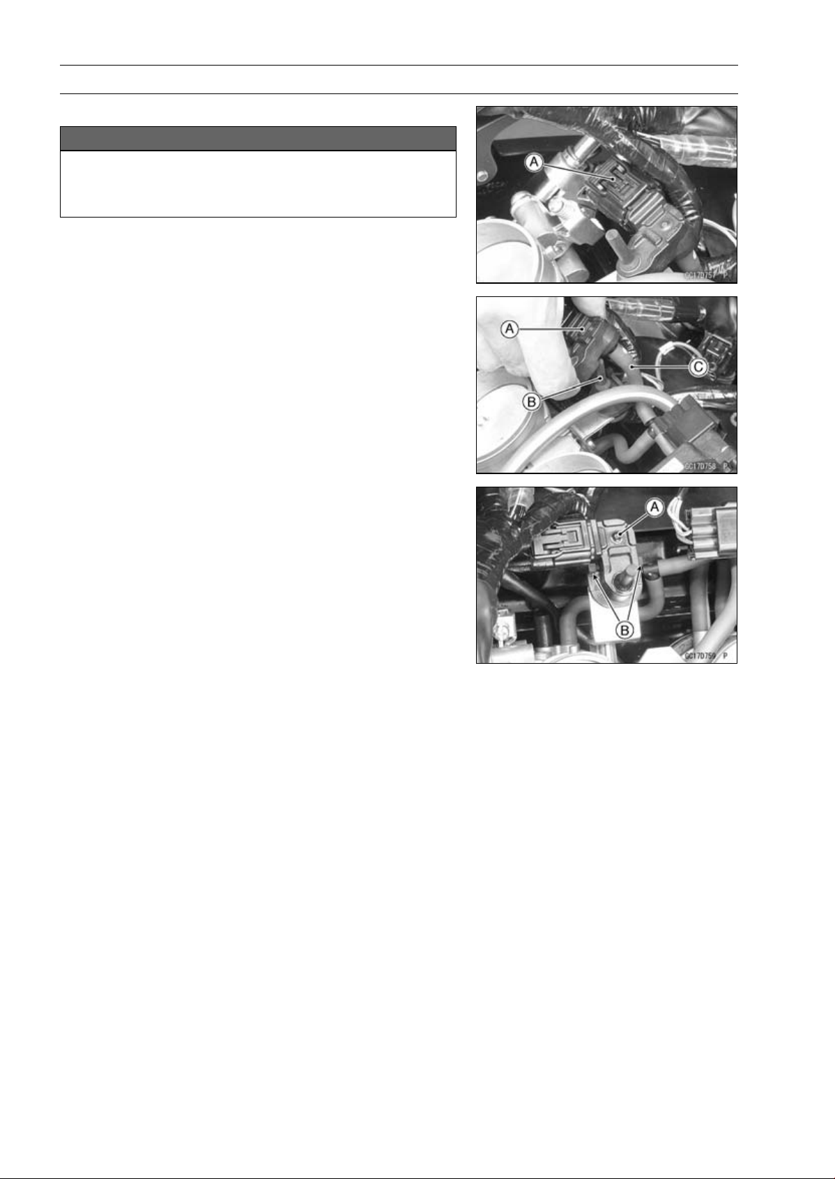
3-48 FUEL SYSTEM (DFI)
Intake Air Pressure Sensor #1 (Service Code 12)
Intake Air Pressure Sensor #1 Removal
NOTICE
Never drop the intake air pressure sensor #1 espe-
cially on a hard surface. Such a shock to the sensor
can damage it.
•
Remove:
Air Cleaner Housing (see Air Cleaner Housing Removal)
Intake Air Pressure Sensor #1 Connector [A]
•
Remove the intake air pressure sensor #1 [A] from the
rubber damper [B] in the bracket and separate the vac-
uum hose [C].
Intake Air Pressure Sensor #1 Installation
NOTE
○
The intake air pressure sensor #1 is the same part as
the intake air pressure sensor #2.
•
Installation is the reverse of removal.
○
Position the intake air pressure sensor #1 [A] between the
projections [B] on the rubber damper.
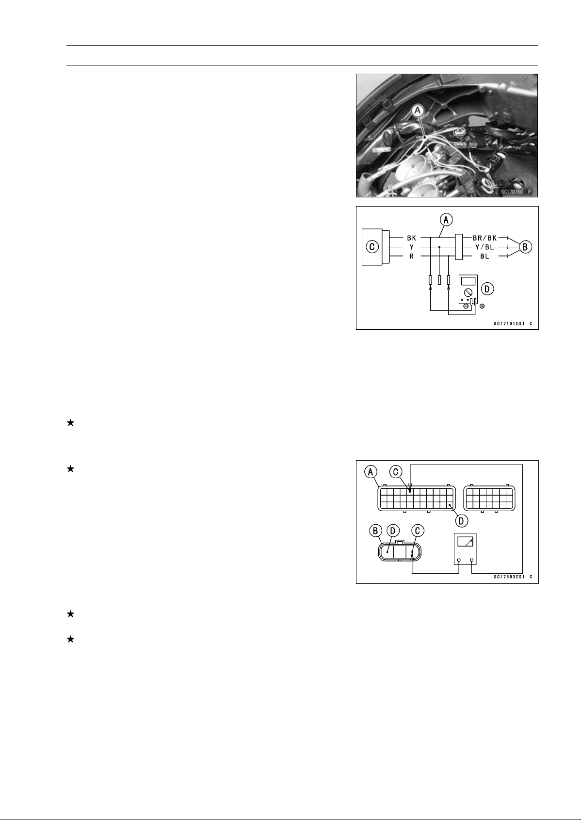
FUEL SYSTEM (DFI) 3-49
Intake Air Pressure Sensor #1 (Service Code 12)
Intake Air Pressure Sensor #1 Input Voltage
Inspection
NOTE
○
Be sure the battery is fully charged.
•
Turn the ignition switch OFF.
•
Remove the air cleaner housing (see Air Cleaner Housing
Removal).
•
Disconnect the intake air pressure sensor #1 connector
and connect the harness adapter [A] between these con-
nectors.
[B] Main Harness
[C] Intake Air Pressure Sensor #1
Special Tool - Measuring Adapter: 57001-1700
•
Connect a digital meter [D] to the harness adapter leads.
Intake Air Pressure Sensor #1 Input Voltage
Connections to Adapter:
Digital Meter (+) R (sensor BL) lead
Digital Meter (–) BK (sensor BR/BK) lead
•
Measure the intake voltage with the engine stopped and
with the connector joined.
•
Turn the ignition switch ON.
Input Voltage
Standard: DC 4.75
∼ 5.25 V
•
Turn the ignition switch OFF.
If the reading is within the standard, check the output volt-
age (see Intake Air Pressure Sensor #1 Output Voltage
Inspection).
If the reading is out of the standard, remove the ECU
and check the wiring for continuity between main harness
connectors.
Special Tool - Hand Tester: 57001-1394
○
Disconnect the ECU and sensor connectors.
Wiring Continuity Inspection
ECU Connector [A]
Intake Air Pressure Sensor #1 Connector [B]
BL lead (ECU terminal 5) [C]
BR/BK lead (ECU terminal 33) [D]
If the wiring is good, check the ECU for its ground and
power supply (see ECU Power Supply Inspection).
If the ground and power supply are good, replace the ECU
(see ECU Removal/Installation).
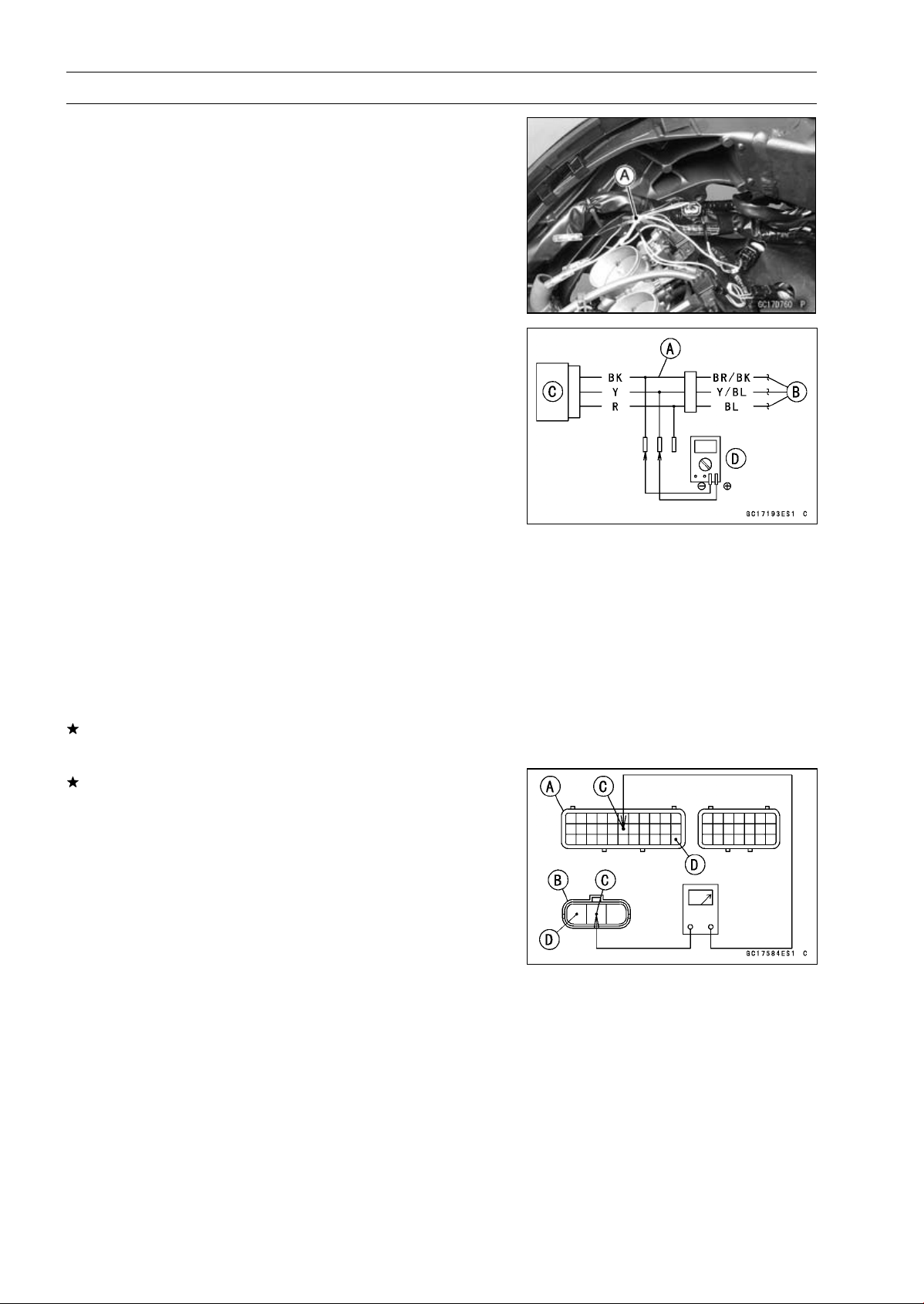
3-50 FUEL SYSTEM (DFI)
Intake Air Pressure Sensor #1 (Service Code 12)
Intake Air Pressure Sensor #1 Output Voltage
Inspection
•
Measure the output voltage at the intake air pressure sen-
sor #1 in the same way as input voltage inspection, note
the following.
○
Disconnect the intake air pressure sensor #1 connector
and connect the harness adapter [A] between these con-
nectors.
[B] Main Harness
[C] Intake Air Pressure Sensor #1
[D] Digital Meter
Special Tool - Measuring Adapter: 57001-1700
Intake Air Pressure Sensor #1 Output Voltage
Connections to Adapter:
Digital Meter (+) Y (sensor Y/BL) lead
Digital Meter (–) BK (sensor BR/BK) lead
•
Measure the output voltage with the engine stopped and
with the connector joined.
•
Turn the ignition switch ON.
Output Voltage
Usable Range:
DC 3.80
∼ 4.20 V at standard
atmospheric pressure (101.32 kPa,
76 cmHg)
NOTE
○
The output voltage changes according to local atmo-
spheric pressure.
•
Turn the ignition switch OFF.
If the reading is out of the usable range, replace the sen-
sor.
If the reading is within the usable range, remove the ECU
and check the wiring for continuity between main harness
connector.
Special Tool - Hand Tester: 57001-1394
○
Disconnect the ECU and sensor connectors.
Wiring Continuity Inspection
ECU Connector [A]
Intake Air Pressure Sensor #1 Connector [B]
Y/BL lead (ECU terminal 17) [C]
BR/BK lead (ECU terminal 33) [D]
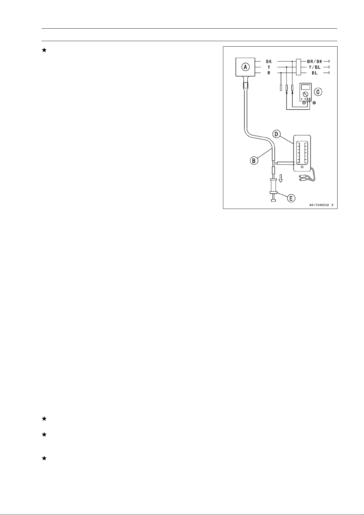
FUEL SYSTEM (DFI) 3-51
Intake Air Pressure Sensor #1 (Service Code 12)
If the wiring is good, check the sensor for various vacuum.
•
Remove the intake air pressure sensor #1 [A] and discon-
nect the vacuum hose from the sensor.
•
Connect an auxiliary hose [B] to the intake air pressure
sensor #1.
•
Temporarily install the intake air pressure sensor #1.
○
Connect a digital meter [C], vacuum gauge [D], the fork
oil level gauge [E] and the harness adapter to the intake
air pressure sensor #1.
Special Tools - Fork Oil Level Gauge: 57001-1290
Vacuum Gauge: 57001-1369
Measuring Adapter: 57001-1700
Intake Air Pressure Sensor #1 Output Voltage
Connections to Adapter:
Digital Meter (+) Y (sensor Y/BL) lead
Digital Meter (–) BK (sensor BR/BK) lead
○
Turn the ignition switch ON.
○
Measure the intake air pressure sensor #1 output voltage
from various vacuum readings, while pulling the handle of
the fork oil level gauge.
○
Check the intake air pressure sensor #1 output voltage,
using the following formula and chart.
Suppose:
Pg: Vacuum Pressure (Gauge) of Throttle Body
Pl: Local Atmospheric Pressure (Absolute) measured by
a barometer
Pv: Vacuum Pressure (Absolute) of Throttle Body
Vv: Sensor Output Voltage (V)
then
Pv = Pl – Pg
For example, suppose the following data is obtained:
Pg = 8 cmHg (Vacuum Gauge Reading)
Pl = 70 cmHg (Barometer Reading)
Vv = 3.2 V (Digital Meter Reading)
then
Pv = 70 – 8 = 62 cmHg (Absolute)
Plot this Pv (62 cmHg) at a point [1] on the chart and draw a
vertical line through the point. Then, you can get the usable
range [2] of the sensor output voltage.
Usable range = 3.08 ∼ 3.48 V
Plot Vv (3.2 V) on the vertical line. → Point [3].
Results: In the chart, Vv is within the usable range and
the sensor is normal.
If the reading is out of the usable range, replace the sen-
sor.
If the reading is within the usable range, check the ECU
for its ground and power supply (see ECU Power Supply
Inspection).
If the ground and power supply are good, replace the ECU
(see ECU Removal/Installation).
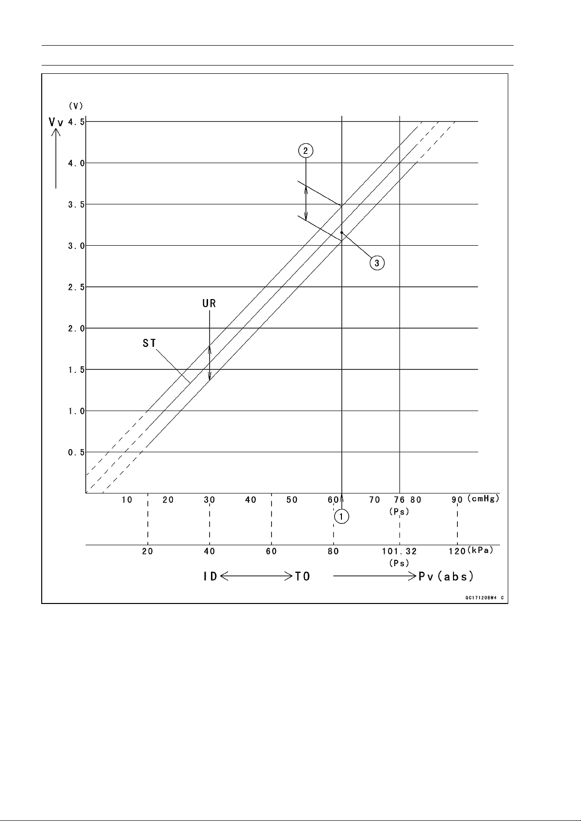
3-52 FUEL SYSTEM (DFI)
Intake Air Pressure Sensor #1 (Service Code 12)
ID: Idling
Ps: Standard Atmospheric Pressure (Absolute)
Pv: Throttle Vacuum Pressure (Absolute)
ST: Standard of Sensor Output Voltage (V)
TO: Throttle Full Open
UR: Usable Range of Sensor Output Voltage (V)
Vv: Intake Air Pressure Sensor #1 Output Voltage (V) (Digital Meter Reading)
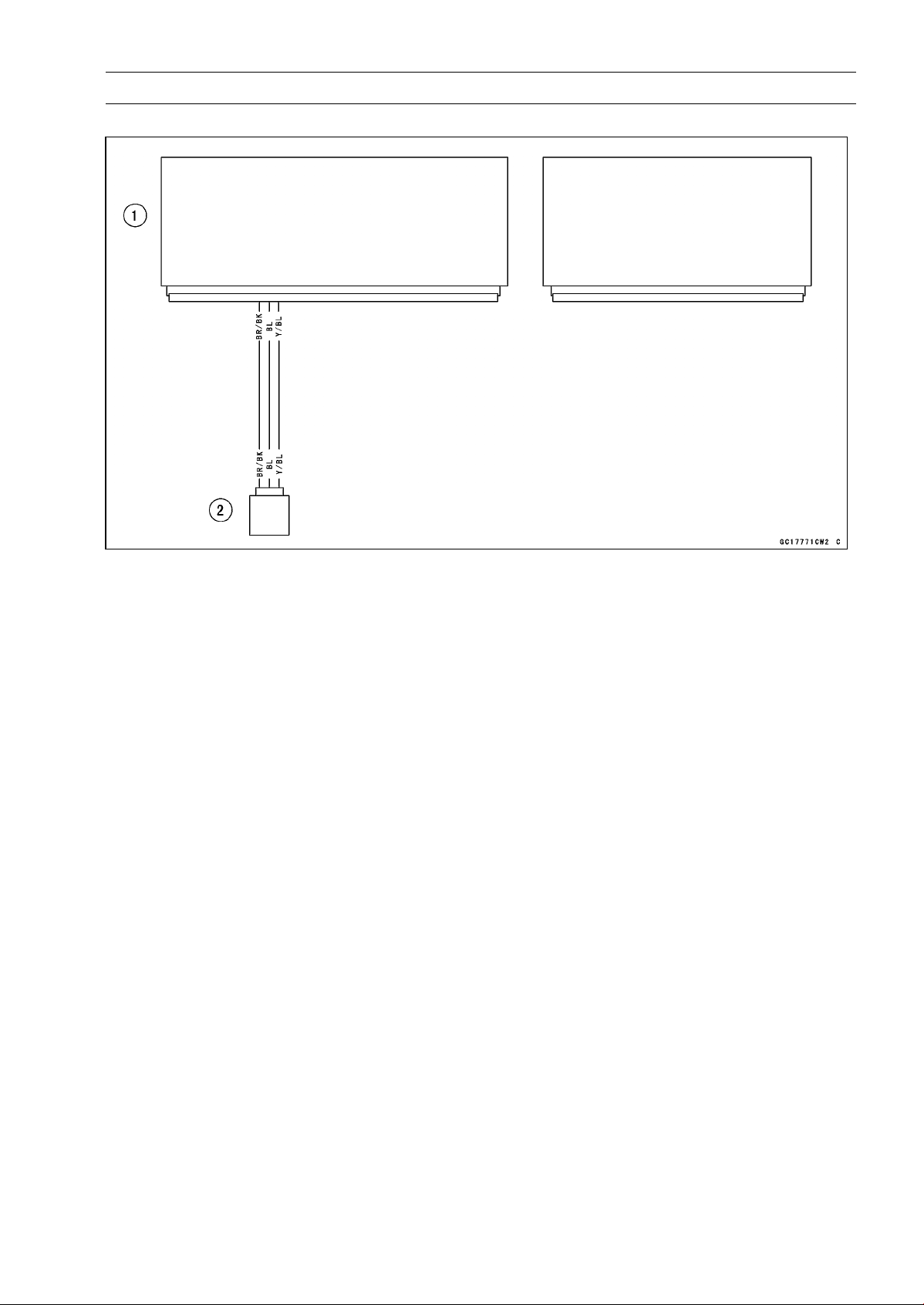
FUEL SYSTEM (DFI) 3-53
Intake Air Pressure Sensor #1 (Service Code 12)
Intake Air Pressure Sensor #1 Circuit
1. ECU
2. Intake Air Pressure Sensor #1
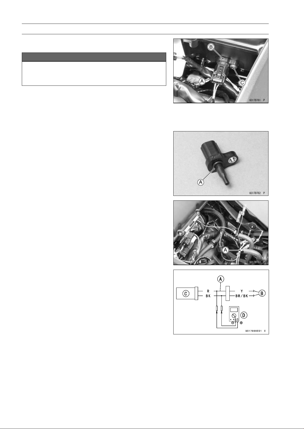
3-54 FUEL SYSTEM (DFI)
Intake Air Temperature Sensor (Service Code 13)
Intake Air Temperature Sensor Removal/Instal-
lation
NOTICE
Never drop the intake air temperature sensor espe-
cially on a hard surface. Such a shock to the sensor
can damage it.
•
Remove the fuel tank (see Fuel Tank Removal).
•
Disconnect the connector [A] from the intake air temper-
ature sensor [B].
•
Remove:
Screw [C]
Intake Air Temperature Sensor
•
Be sure to install the O-ring [A].
•
Install the intake air temperature sensor.
•
Tighten:
Torque - Intake Air Temperature Sensor Screw: 1.2 N·m
(0.12 kgf·m, 11 in·lb)
Intake Air Temperature Sensor Output Voltage
Inspection
NOTE
○
Be sure the battery is fully charged.
•
Turn the ignition switch OFF.
•
Remove the fuel tank (see Fuel Tank Removal).
•
Disconnect the intake air temperature sensor connector
and connect the harness adapter [A] between these con-
nectors as shown.
Main Harness [B]
Intake Air Temperature Sensor [C]
Special Tool - Measuring Adapter: 57001-1700
•
Connect a digital meter [D] to the harness adapter leads.
Intake Air Temperature Sensor Output Voltage
Connections to Adapter:
Digital Meter (+) R (sensor Y) lead
Digital Meter (–) BK (sensor BR/BK) lead
•
Measure the output voltage with the engine stopped and
the connector joined.
•
Turn the ignition switch ON.
Output Voltage
Standard: About DC 2.25
∼ 2.50 V at 20°C (68°F)
NOTE
○
The output voltage changes according to the intake air
temperature.
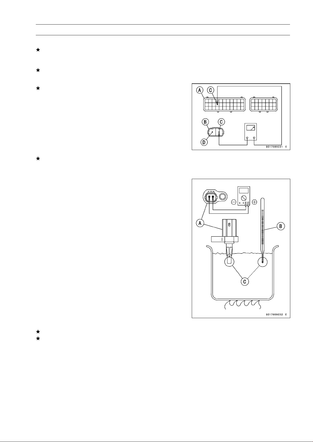
FUEL SYSTEM (DFI) 3-55
Intake Air Temperature Sensor (Service Code 13)
•
Turn the ignition switch OFF.
If the reading is within the standard, check the ECU for
its ground, and power supply (see ECU Power Supply
Inspection).
If the ground and power supply are good, replace the ECU
(see ECU Removal/Installation).
If the reading is out of the standard, remove the ECU
and check the wiring for continuity between main harness
connectors.
○
Disconnect the ECU and sensor connectors.
Wiring Inspection
ECU Connector [A]
Intake Air Temperature Sensor Connector [B]
Y lead (ECU terminal 15) [C]
BR/BK lead (ECU terminal 33) [D]
If the wiring is good, check the intake air temperature sen-
sor resistance (see Intake Air Temperature Sensor Resis-
tance Inspection).
Intake Air Temper
ature Sensor Resistance
Inspection
•
Remove the intake air temperature sensor (see Intake Air
Temperature Sensor Removal/Ins
tallation).
•
Suspend the sensor [A] in a container of machine oil so
that the heat-sensitive portion is submerged.
•
Suspend a thermometer [B] with the heat-sen
sitive por-
tion [C] located in almost the same depth with the sensor.
NOTE
○
The sensor and thermometer must not touch the con-
tainer side or bottom.
•
Place the container over a source of heat and gradually
raise the temperature of the oil while stirring the oil gently
for even temperature.
•
Using a digital meter, measure the internal resistance
of the sensor across the terminals at the temperatures
shown in the following.
Intake Air Temperature Sensor Resistance
Standard: 5.4
∼ 6.6 k at 0°C (32°F)
0.29
∼ 0.39 k at 80°C (176°F)
If the reading is out of the standard, replace the sensor.
If the reading is within the standard, but the problem still
exists, replace the ECU (see ECU Removal/Installation).
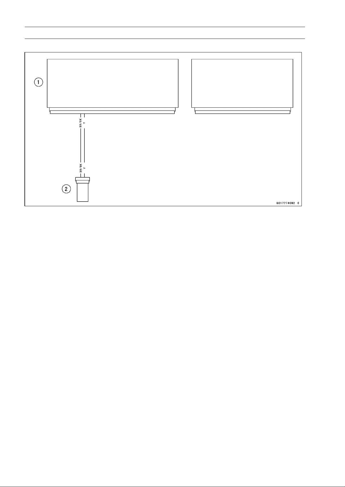
3-56 FUEL SYSTEM (DFI)
Intake Air Temperature Sensor (Service Code 13)
Intake Air Temperature Sensor Circuit
1. ECU
2. Intake Air Temperature Sensor
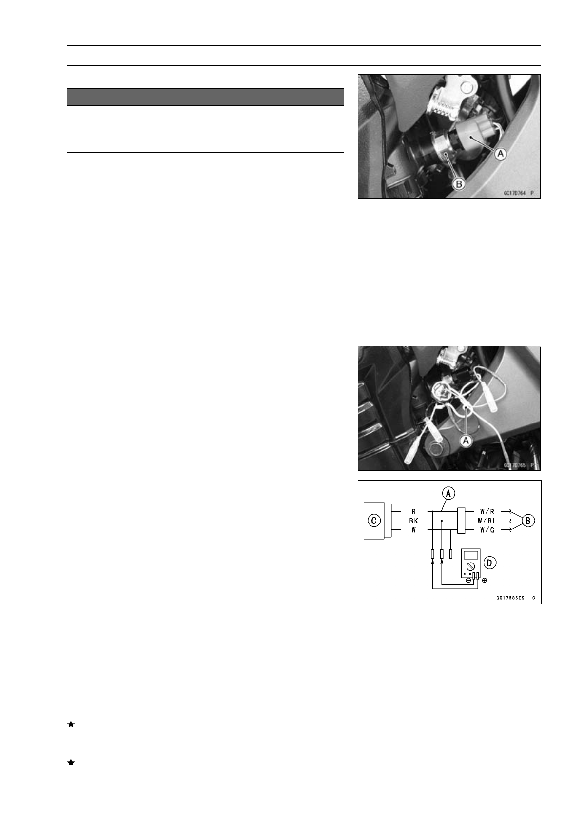
FUEL SYSTEM (DFI) 3-57
Water Temperature Sensor (Service Code 14)
Water Temperature Sensor Removal/Installation
NOTICE
Never drop the water temperature sensor especially
on a hard surface. Such a shock to the sensor can
damage it.
•
Drain the coolant (see Coolant Change in the Periodic
Maintenance chapter).
•
Remove:
Connector [A]
Water Temperature Sensor [B]
•
Replace the gasket with a new one, and using a cleaning
fluid, clean off any oil or dirt on the new gasket and dry it
with a clean cloth.
•
Tighten the water temperature sensor.
Torque - Water Temperature Sensor: 30 N·m (3.1 kgf·m, 22
ft·lb)
•
Fill the engine with coolant and bleed the air from the cool-
ing system (see Coolant Change in the Periodic Mainte-
nance chapter).
Water Temperature Sensor Output Voltage
Inspection
NOTE
○
Be sure the battery is fully charged.
•
Turn the ignition switch OFF.
•
Disconnect the water temperature sensor connector and
connect the harness adapter [A] between these connec-
tors as shown.
Sub Harness [B]
Water Temperature Sensor [C]
Special Tool - Measuring Adapter: 57001-1700
•
Connect a digital meter [D] to the harness adapter leads.
Water Temperature Sensor Output Voltage
Connections to Adapter:
Digital Meter (+) R (sensor W/R) lead
Digital Meter (–) BK (sensor W/BL) lead
•
Measure the output voltage with the engine stopped and
with the connector joined.
•
Turn the ignition switch ON.
Output Voltage
Standard: About DC 2.80
∼ 2.97 V at 20°C (68°F)
NOTE
○
The output voltage changes according to the coolant
temperature in the engine.
•
Turn the ignition switch OFF.
If the reading is within the standard, check the ECU for
its ground and power supply (see ECU Power Supply In-
spection).
If the ground and power supply are good, replace the ECU
(see ECU Removal/Installation).
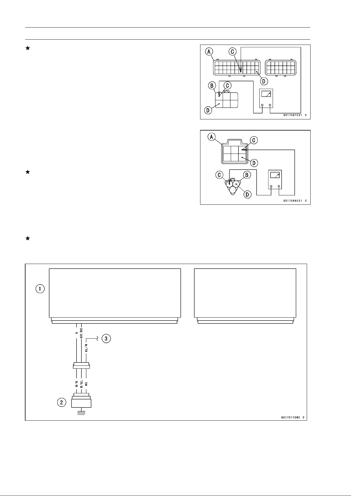
3-58 FUEL SYSTEM (DFI)
Water Temperature Sensor (Service Code 14)
If the reading is out of the standard, remove the ECU
and check the wiring for continuity between main and sub
harness connectors.
○
Disconnect the ECU and sensor connectors.
Wiring Inspection
ECU Connector [A]
Sub Harness Connector [B]
O lead (ECU terminal 29) [C]
BR/BK lead (ECU terminal 33) [D]
Sub Harness Connector [A]
Sub Harness Connector [B]
W/R lead [C]
W/BL lead [D]
If the wiring is good, check the water temperature sensor
resistance (see Water Temperature Sensor Resistance
Inspection).
Water Temperature Sensor Resistance Inspection
•
Refer to the Water Temperature Sensor Inspection in the
Electrical System chapter.
If the reading is within the standard, but the problem still
exists, replace the ECU (see ECU Removal/Installation).
Water Temperature Sensor Circuit
1. ECU
2. Water Temperature Sensor
3. To Meter Unit
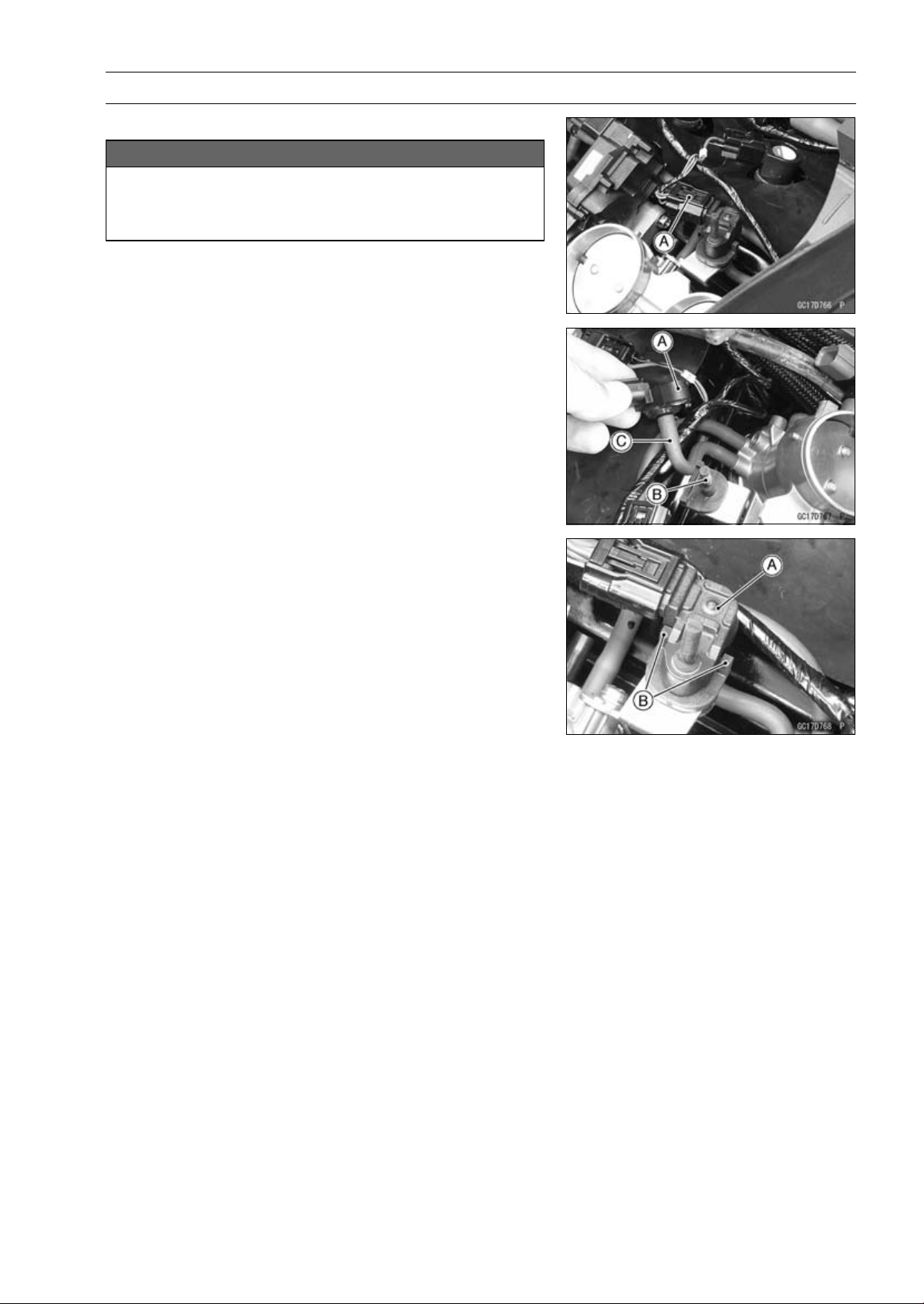
FUEL SYSTEM (DFI) 3-59
Intake Air Pressure Sensor #2 (Service Code 16)
Intake Air Pressure Sensor #2 Removal
NOTICE
Never drop the intake air pressure sensor #2 espe-
cially on a hard surface. Such a shock to the sensor
can damage it.
•
Remove the air cleaner housing (see Air Cleaner Housing
Removal).
•
Disconnect the sensor connector [A].
•
Remove the intake air pressure sensor #2 [A] from the
rubber damper [B] in the bracket and separate the vac-
uum hose [C].
Intake Air Pressure Sensor #2 Installation
NOTE
○
The intake air pressure sensor #2 is the same part as
the intake air pressure sensor #1.
•
Installation is the reverse of removal.
○
Position the intake air pressure sensor #2 [A] between the
projection [B] on the rubber damper.
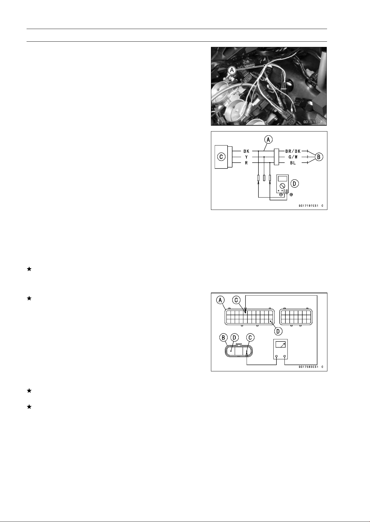
3-60 FUEL SYSTEM (DFI)
Intake Air Pressure Sensor #2 (Service Code 16)
Intake Air Pressure Sensor #2 Input Voltage
Inspection
NOTE
○
Be sure the battery is fully charged.
•
Turn the ignition switch OFF.
•
Remove the air cleaner housing (see Air Cleaner Housing
Removal).
•
Disconnect the intake air pressure sensor #2 connector
and connect the harness adapter [A] between these con-
nectors.
[B] Main Harness
[C] Intake Air Pressure Sensor #2
Special Tool - Measuring Adapter: 57001-1700
•
Connect a digital meter [D] to the harness adapter leads.
Intake Air Pressure Sensor #2 Input Voltage
Connections to Adapter:
Digital Meter (+) R (sensor BL) lead
Digital Meter (–) BK (sensor BR/BK) lead
•
Measure the input voltage with the engine stopped and
with the connector joined.
•
Turn the ignition switch ON.
Input Voltage
Standard: DC 4.75
∼ 5.25 V
•
Turn the ignition switch OFF.
If the reading is within the standard, check the output volt-
age (see Intake Air Pressure Sensor #2 Output Voltage
Inspection).
If the reading is out of the standard, remove the ECU
and check the wiring for continuity between main harness
connectors.
Special Tool - Hand Tester: 57001-1394
○
Disconnect the ECU and sensor connectors.
Wiring Continuity Inspection
ECU Connector [A]
Intake Air Pressure Sensor #2 Connector [B]
BL lead (ECU terminal 5) [C]
BR/BK lead (ECU terminal 33) [D]
If the wiring is good, check the ECU for its ground and
power supply (see ECU Power Supply Inspection).
If the ground and power supply are good, replace the ECU
(see ECU Removal/Installation).
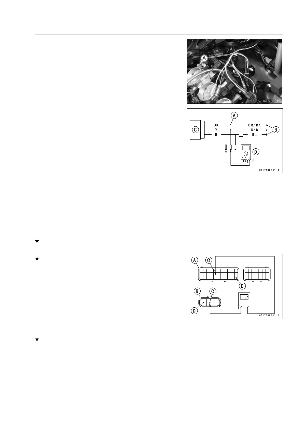
FUEL SYSTEM (DFI) 3-61
Intake Air Pressure Sensor #2 (Service Code 16)
Intake Air Pressure Sensor #2 Output Voltage
Inspection
•
Measure the output voltage at the intake air pressure sen-
sor #2 in the same way as input voltage inspection, note
the following.
○
Disconnect the intake air pressure sensor #2 connector
and connect the harness adapter [A] between these con-
nectors.
[B] Main Harness
[C] Intake Air Pressure Sensor #2
[D] Digital Meter
Special Tool - Measuring Adapter: 57001-1700
Intake Air Pressure Sensor #2 Output Voltage
Connections to Adapter:
Digital Meter (+) Y (sensor G/W) lead
Digital Meter (–) BK (sensor BR/BK) lead
•
Measure the output voltage with the engine stopped and
with the connector joined.
•
Turn the ignition switch ON.
Output Voltage
Usable Range:
DC 3.80
∼ 4.20 V at standard
atmospheric pressure (101.32 kPa, 76
cmHg absolute)
NOTE
○
The output voltage changes according to the local at-
mospheric pressure.
•
Turn the ignition switch OFF.
If the reading is out of the usable range, replace the sen-
sor.
If the reading is within the usable range, remove the ECU
and check the wiring for continuity between main harness
connector.
Special Tool - Hand Tester: 57001-1394
○
Disconnect the ECU and sensor connectors.
Wiring Continuity Inspection
ECU Connector [A]
Intake Air Pressure Sensor #2 Connector [B]
G/W lead (ECU terminal 16) [C]
BR/BK lead (ECU terminal 33) [D]
If the wiring is good, check the sensor for various vac-
uum (see Intake Air Pressure Sensor #1 Output Voltage
Inspection).
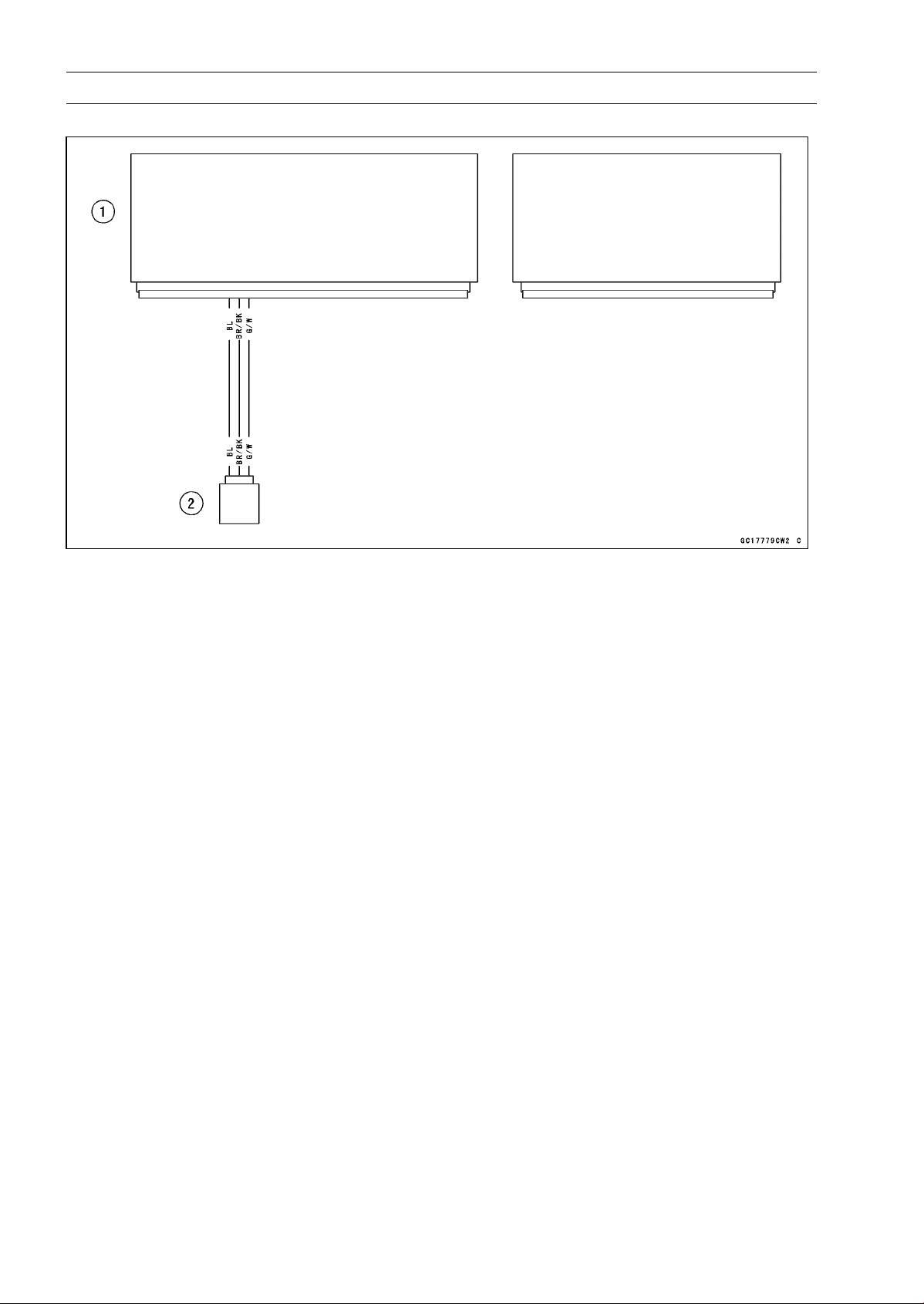
3-62 FUEL SYSTEM (DFI)
Intake Air Pressure Sensor #2 (Service Code 16)
Intake Air Pressure Sensor #2 Circuit
1. ECU
2. Intake Air Pressure Sensor #2
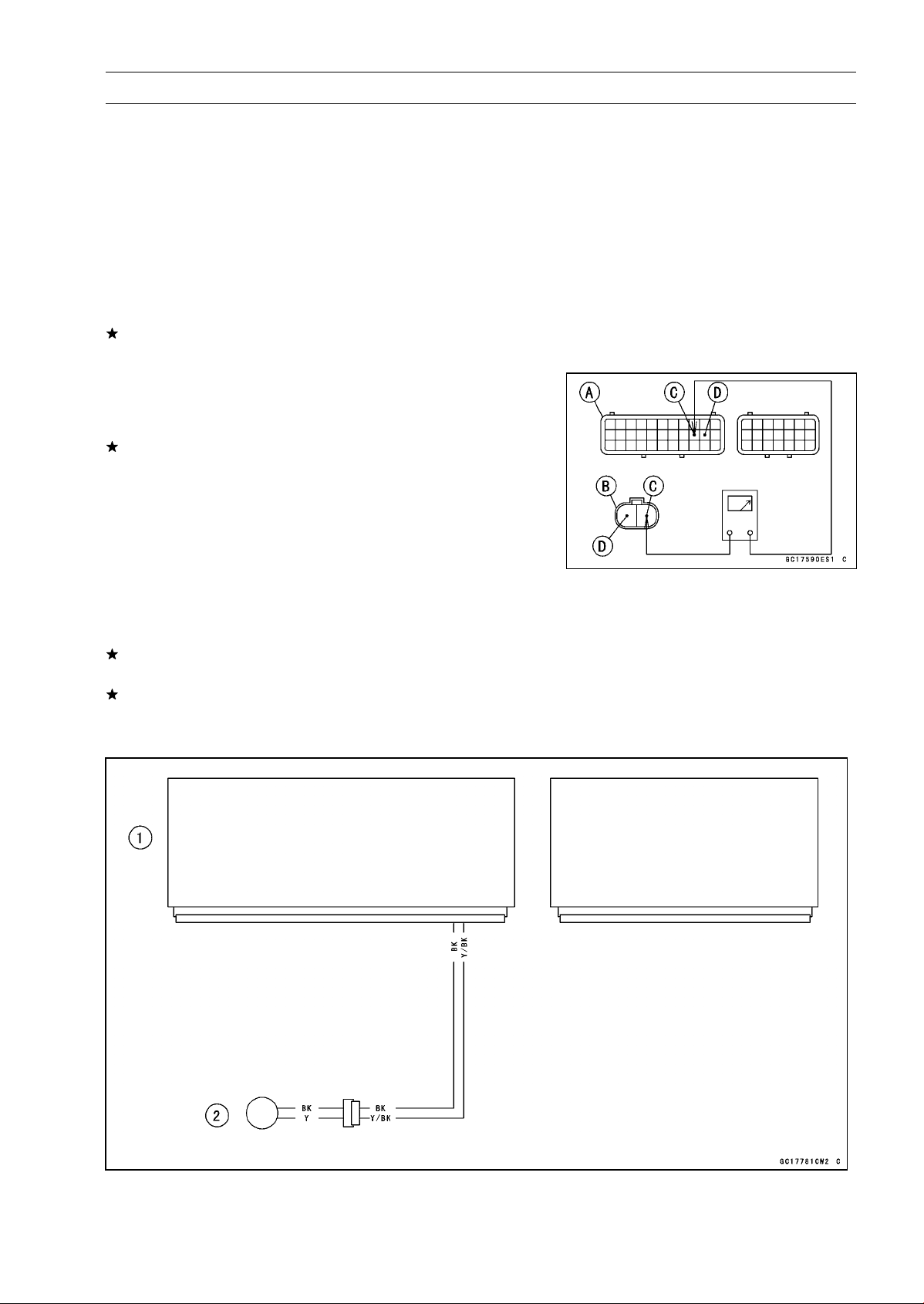
FUEL SYSTEM (DFI) 3-63
Crankshaft Sensor (Service Code 21)
The crankshaft sensor has no power source, and when
the engine stops, the crankshaft sensor generates no sig-
nals.
Crankshaft Sensor Removal/Installation
•
Refer to the Crankshaft Sensor Removal/Installation in
the Electrical System chapter.
Crankshaft Sensor Resistance Inspection
•
Refer to the Crankshaft Sensor Inspection in the Electrical
System chapter.
If the reading is within the standard, check the peak volt-
age (see Crankshaft Sensor Peak Voltage Inspection).
Crankshaft Sensor Peak Voltage Inspection
•
Refer to the Crankshaft Sensor Peak Voltage Inspection
in the Electrical System chapter.
If the reading is within the standard, remove the ECU and
check the wiring for continuity between main harness con-
nectors.
○
Disconnect the ECU and sensor connectors.
Wiring Inspection
ECU Connector [A]
Crankshaft Sensor Connector [B]
Y/BK lead (ECU terminal 20) [C]
BK lead (ECU terminal 21) [D]
If the wiring is good, check the ECU for its ground and
power supply (see ECU Power Supply Inspection).
If the ground and power supply are good, replace the ECU
(see ECU Removal/Installation).
Crankshaft Sensor Circuit
1. ECU
2. Crankshaft Sensor
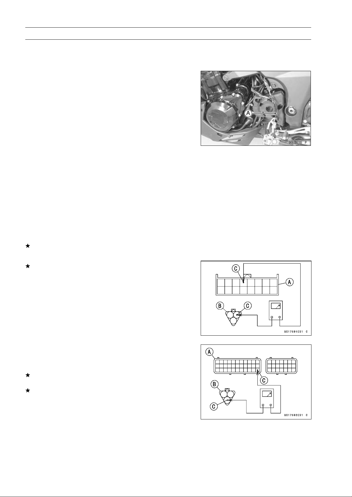
3-64 FUEL SYSTEM (DFI)
Speed Sensor (Service Code 24, 25)
Speed Sensor Removal/Installation
•
Refer to the Speed Sensor Removal/Installation in the
Electrical System chapter.
Speed Sensor Input Voltage Inspection
NOTE
○
Be sure the battery is fully charged.
•
Turn the ignition switch OFF.
•
Disconnect the speed sensor connector and connect the
harness adapter [A] between these connectors.
Special Tool - Speed Sensor Measuring Adapter: 57001
-1400
•
Connect a digital meter to the harness adapter leads.
Speed Sensor Input Voltage
Connections to Adapter:
Digital Meter (+) BL (sensor P) lead
Digital Meter (–) BK/BL (sensor BK) lead
•
Measure the input voltage with the engine stopped and
with the connector joined.
•
Turn the ignition switch ON.
Input Voltage
Standard: About DC 9
∼ 11 V
•
Turn the ignition switch OFF.
If the reading is within the standard, check the output volt-
age (see Speed Sensor Output Voltage Inspection).
If the reading is out of the standard, remove the ECU
and check the wiring for continuity between main harness
connectors.
○
Disconnect the ECU and sensor connectors.
Wiring Inspection
Speed Meter Connector [A]
Speed Sensor Connector [B]
BL lead [C]
Speed Meter Connector [A]
Speed Sensor Connector [B]
BR/BK lead (ECU terminal 33) [C]
If the wiring is good, check the ECU for its ground and
power supply (see ECU Power Supply Inspection).
If the ground and power supply are good, replace the ECU
(see ECU Removal/Installation).
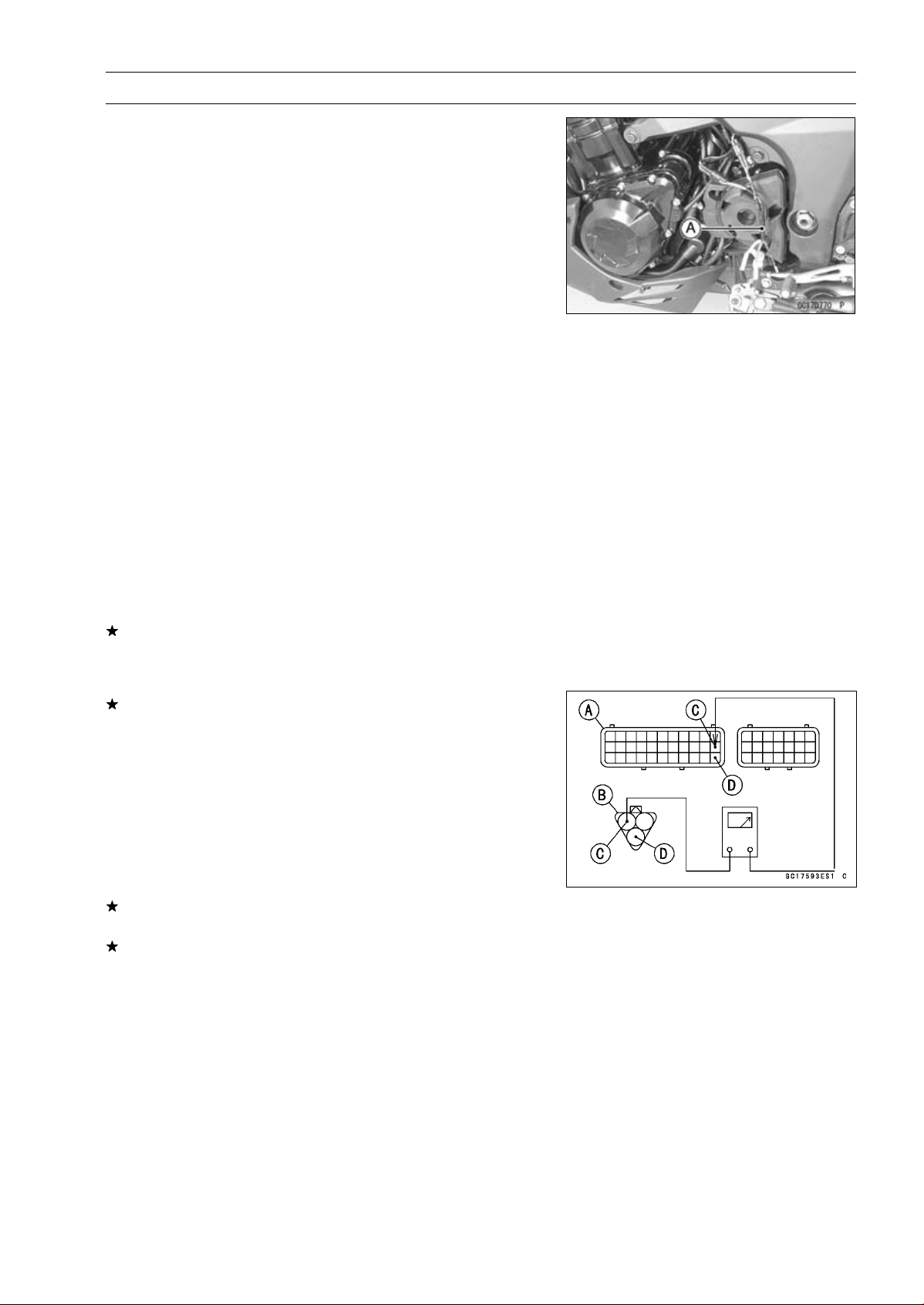
FUEL SYSTEM (DFI) 3-65
Speed Sensor (Service Code 24, 25)
Speed Sensor Output Voltage Inspection
•
Using the stand, raise the rear wheel off the ground.
•
Measure the output voltage at the speed sensor in the
same way as input voltage inspection, note the following.
○
Disconnect the speed sensor connector and connect the
harness adapter [A] between these connectors.
Special Tool - Speed Sensor Measuring Adapter: 57001
-1400
Speed Sensor Output Voltage
Connections to Adapter:
Digital Meter (+) Y/W (sensor Y) lead
Digital Meter (–) BK/BL (sensor BK) lead
•
Measure the output voltage with the engine stopped and
with the connector joined.
•
Turn the ignition switch ON.
Output Voltage
Standard: Less than DC 0.6 V or over than 4.8 V at
ignition switch ON and 0 km/h
NOTE
○
Rotate the rear wheel by hand, confirm the output volt-
age will be raise or lower.
•
Turn the ignition switch OFF.
If the reading is out of the standard, check the speed sen-
sor (see Speed Sensor Inspection in the Electrical System
chapter).
If the reading is within the standard, remove the ECU and
check the wiring for continuity between main harness con-
nectors.
○
Disconnect the ECU and sensor connectors.
Wiring Inspection
ECU Connector [A]
Speed Sensor Connector [B]
P lead (ECU terminal 22) [C]
BR/BK lead (ECU terminal 33) [D]
If the wiring is good, check the ECU for its ground and
power supply (see ECU Power Supply Inspection).
If the ground and power supply are good, replace the ECU
(see ECU Removal/Installation).
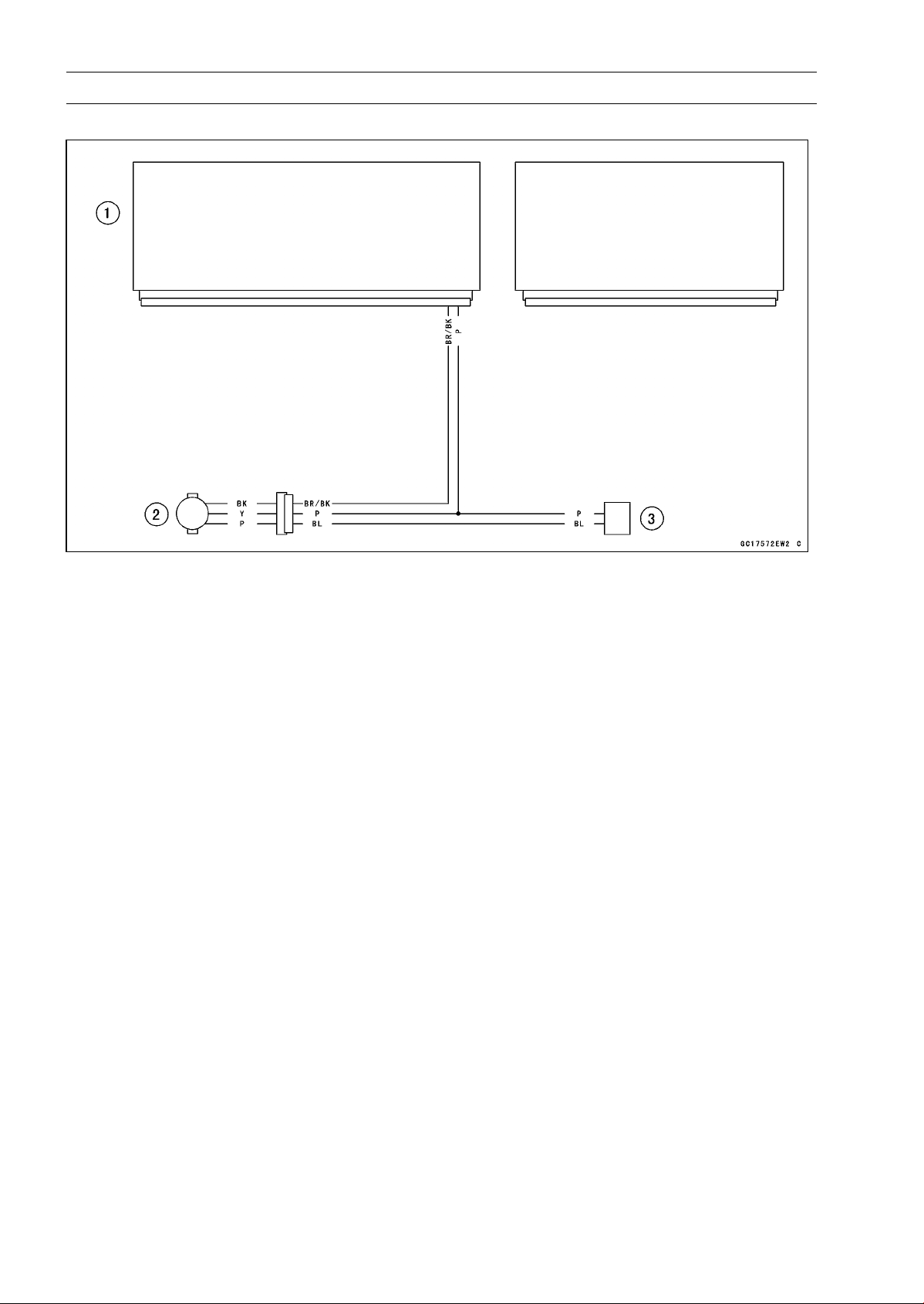
3-66 FUEL SYSTEM (DFI)
Speed Sensor (Service Code 24, 25)
Speed Sensor Circuit
1. ECU
2. Speed Sensor
3. Meter Unit
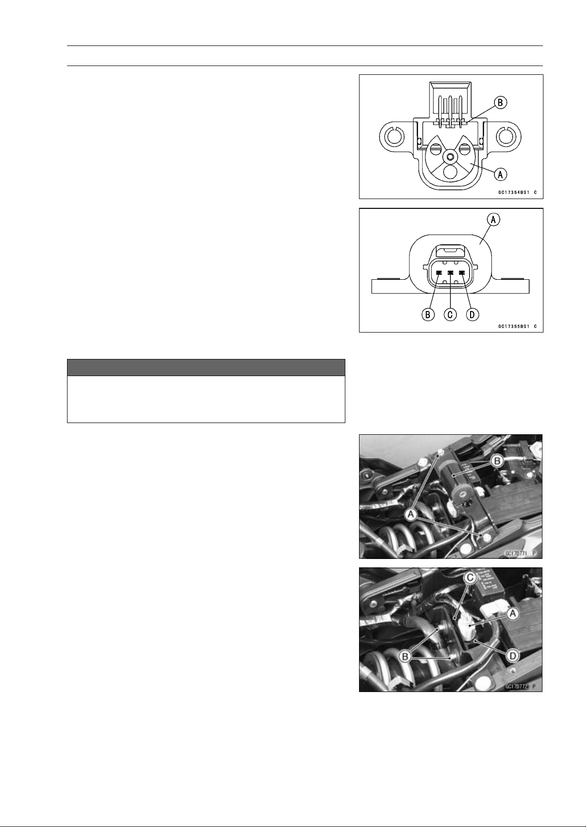
FUEL SYSTEM (DFI) 3-67
Vehicle-down Sensor (Service Code 31)
This sensor has a weight [A] with two magnets inside,
and sends a signal to the ECU. But when the motorcycle
banks 60 ∼ 70° or more to either side (in fact falls down),
the weight turns and the signal changes. The ECU senses
this change, and stops the fuel pump relay, the fuel injectors
and the ignition system.
Hall IC [B]
When the motorcycle is down, the ignition switch is left
ON. If the starter button is pushed, the electric starter turns
but the engine does not start. To start the engine again,
raise the motorcycle, turn the ignition switch OFF, and then
ON.
Vehicle-down Sensor [A]
Ground Terminal BR/BK [B]
Output Terminal Y/G [C]
Power Source Terminal BL [D]
Vehicle-down Sensor Removal
NOTICE
Never drop the vehicle-down sensor especially on
a hard surface. Such a shock to the sensor can
damage it.
•
Remove:
Fuel Tank (See Fuel Tank Removal)
Bolts [A]
Fuel Tank Bracket [B]
•
Remove:
Rear Seat (see Rear Seat Removal in the Frame chap-
ter)
Connector [A]
Bolts [B] and Bracket [C]
Vehicle-down Sensor [D]
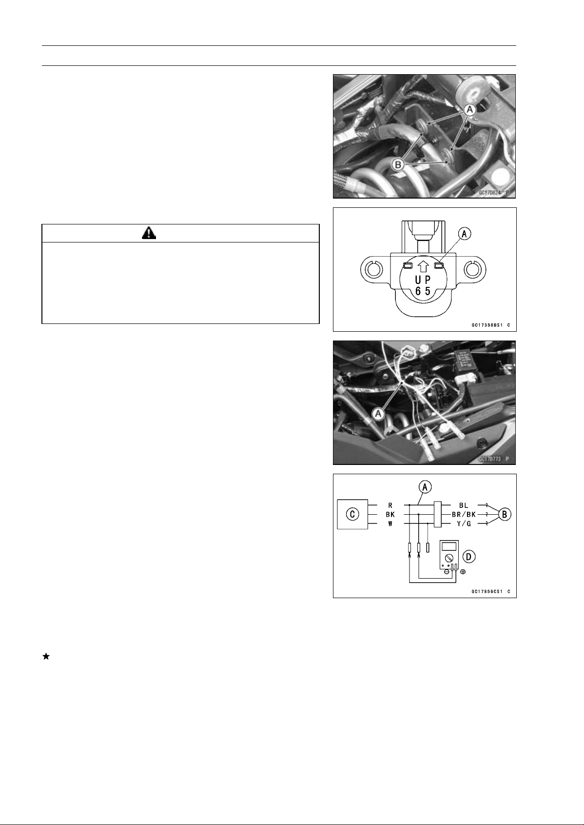
3-68 FUEL SYSTEM (DFI)
Vehicle-down Sensor (Service Code 31)
Vehicle-down Sensor Installation
•
Be sure to install the rubber dampers [A] and collars [B]
on the battery case.
•
The UP mark [A] of the sensor should face upward.
WARNING
Incorrect installation of the vehicle-down sensor
could cause sudden loss of engine power. The
rider could lose balance during certain riding situ-
ations for an accident resulting in injury or death.
Ensure that the vehicle-down sensor is held in
place by the battery case.
Vehicle-down Sensor Input Voltage Inspection
NOTE
○
Be sure the battery is fully charged.
•
Turn the ignition switch OFF.
•
Disconnect the vehicle-down sensor connector and con-
nect the harness adapter [A] between these connectors
as shown.
Main Harness [B]
Vehicle-down Sensor [C]
Special Tool - Measuring Adapter: 57001-1700
•
Connect a digital meter [D] to the harness adapter leads.
Vehicle-down Sensor Input Voltage
Connections to Adapter:
Digital Meter (+) R (sensor BL) lead
Digital Meter (–) BK (sensor BR/BK) lead
•
Measure the input voltage with the engine stopped and
with the connector joined.
•
Turn the ignition switch ON.
Input Voltage
Standard: DC 4.75
∼ 5.25 V
•
Turn the ignition switch OFF.
If the reading is within the standard, check the output volt-
age (see Vehicle-down Sensor Output Voltage Inspec-
tion).
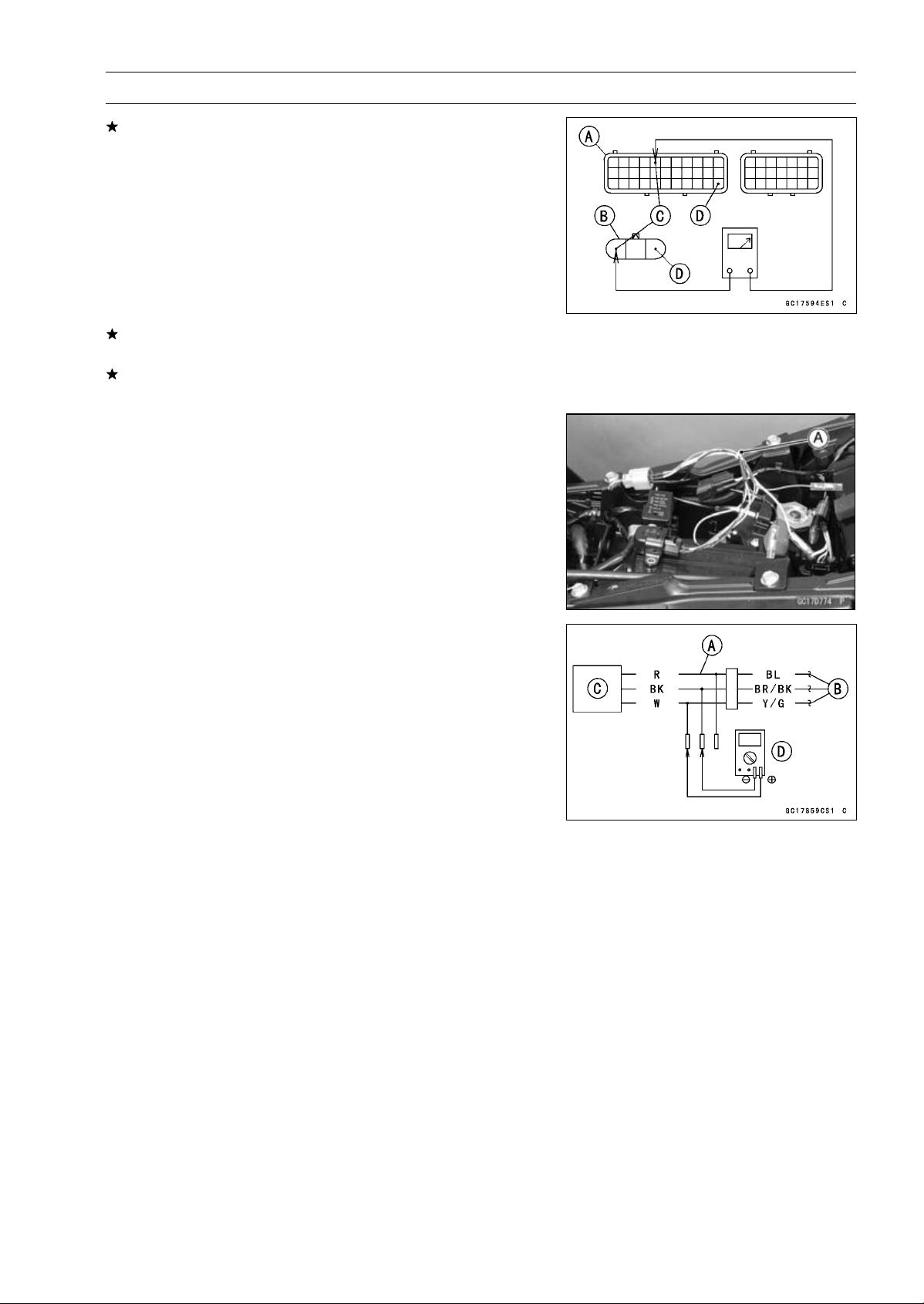
FUEL SYSTEM (DFI) 3-69
Vehicle-down Sensor (Service Code 31)
If the reading is out of the standard, remove the ECU
and check the wiring for continuity between main harness
connectors.
○
Disconnect the ECU and sensor connections.
Wiring Inspection
ECU Connector [A]
Vehicle-down Sensor Connector [B]
BL lead (ECU terminal 5) [C]
BR/BK lead (ECU terminal 33) [D]
If the wiring is good, check the ECU for its ground and
power supply (see ECU Power Supply Inspection).
If the ground and power supply are good, replace the ECU
(see ECU Removal/Installation).
Vehicle-down Sensor Output Voltage Inspection
•
Remove the vehicle-down sensor (see Vehicle-down
Sensor Removal).
•
Connect the harness adapter [A] to the vehicle-down sen-
sor connectors as shown.
Special Tool - Measuring Adapter: 57001-1700
Main Harness [B]
Vehicle-down Sensor [C]
•
Connect a digital meter [D] to the harness adapter leads.
Vehicle-down Sensor Output Voltage
Connections to Adapter:
Digital Meter (+) W (sensor Y/G) lead
Digital Meter (–) BK (sensor BR/BK) lead
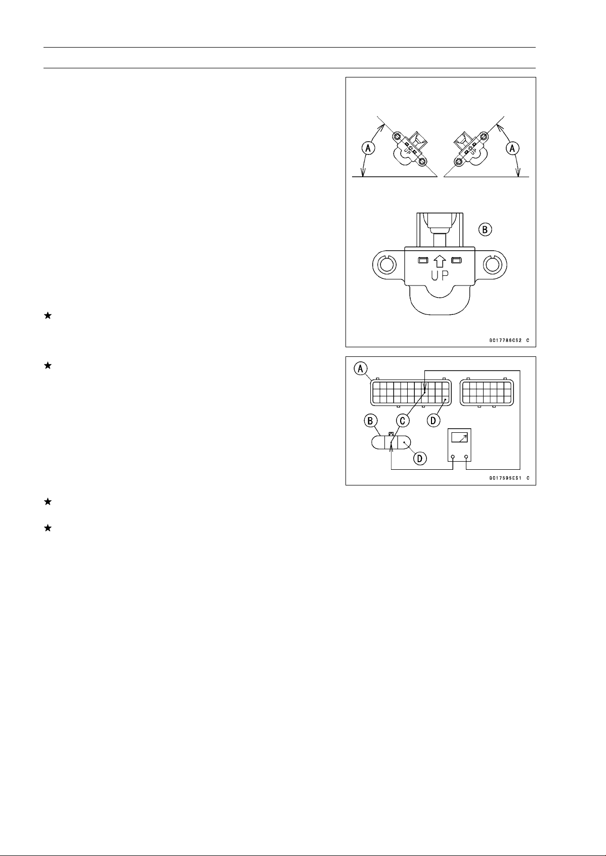
3-70 FUEL SYSTEM (DFI)
Vehicle-down Sensor (Service Code 31)
•
Hold the sensor vertically.
•
Measure the output voltage with the engine stopped and
with the connector joined.
•
Turn the ignition switch ON.
•
Tilt the sensor 60 ∼ 70° or more [A] right or left, then hold
the sensor almost vertical with the arrow mark pointed up
[B], and measure the output voltage.
Output Voltage
Standard: Withsensortilted60
∼ 70° or more right or
left: DC 0.65
∼ 1.35 V
With sensor arrow mark pointed up: DC
3.55
∼ 4.45 V
NOTE
○
If you need to test again, turn the ignition switch OFF,
and then ON.
•
Turn the ignition switch OFF.
If the reading is out of the standard, replace the sensor.
If the reading is within the standard, remove the ECU and
check the wiring for continuity between main harness con-
nectors.
○
Disconnect the ECU and sensor connectors.
Wiring Inspection
ECU Connector [A]
Vehicle-down Sensor Connector [B]
Y/G lead (ECU terminal 19) [C]
BR/BK lead (ECU terminal 33) [D]
If the wiring is good, check the ECU for its ground and
power supply (see ECU Power Supply Inspection).
If the ground and power supply are good, replace the ECU
(see ECU Removal/Installation).
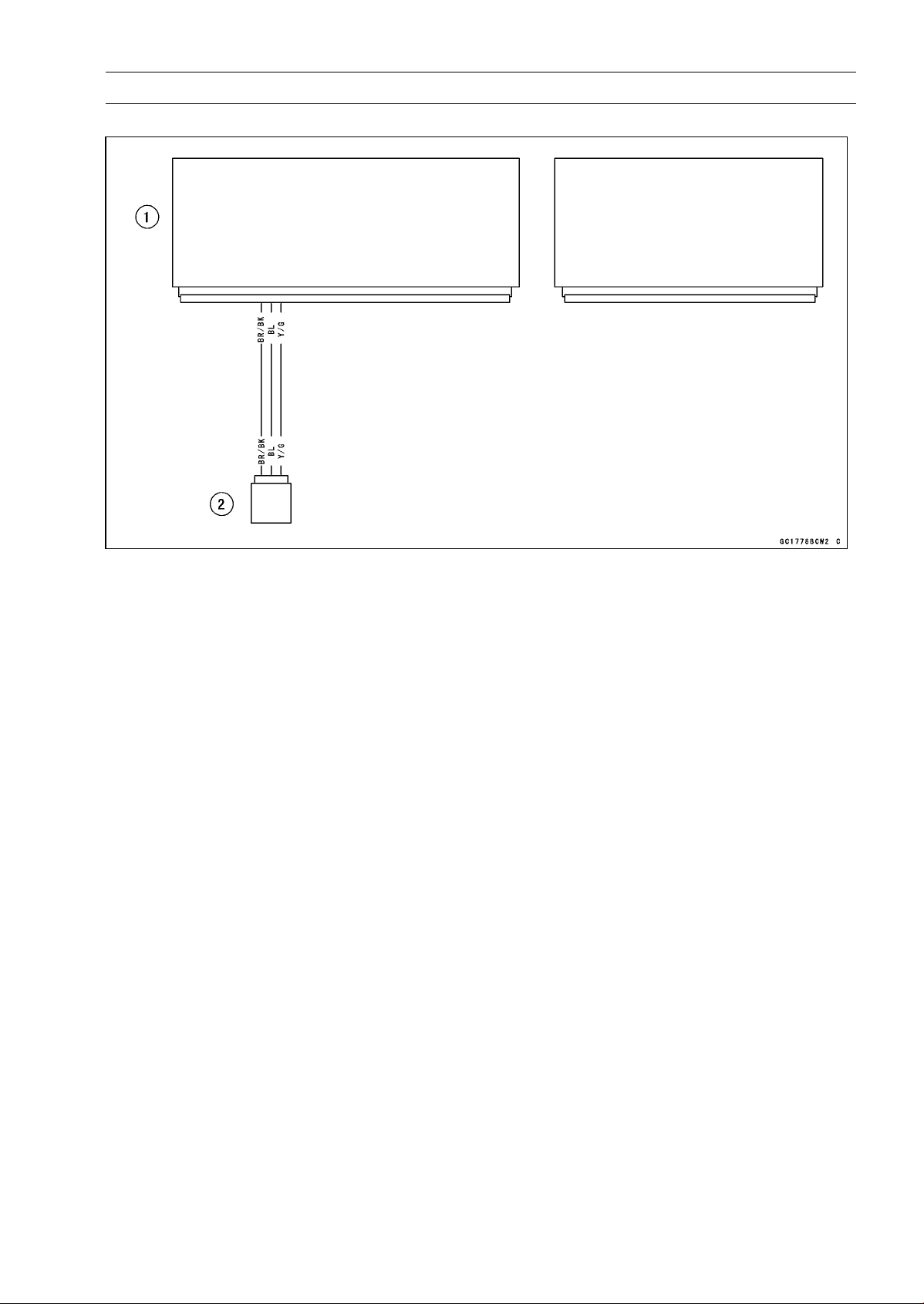
FUEL SYSTEM (DFI) 3-71
Vehicle-down Sensor (Service Code 31)
Vehicle-down Sensor Circuit
1. ECU
2. Vehicle-down Sensor
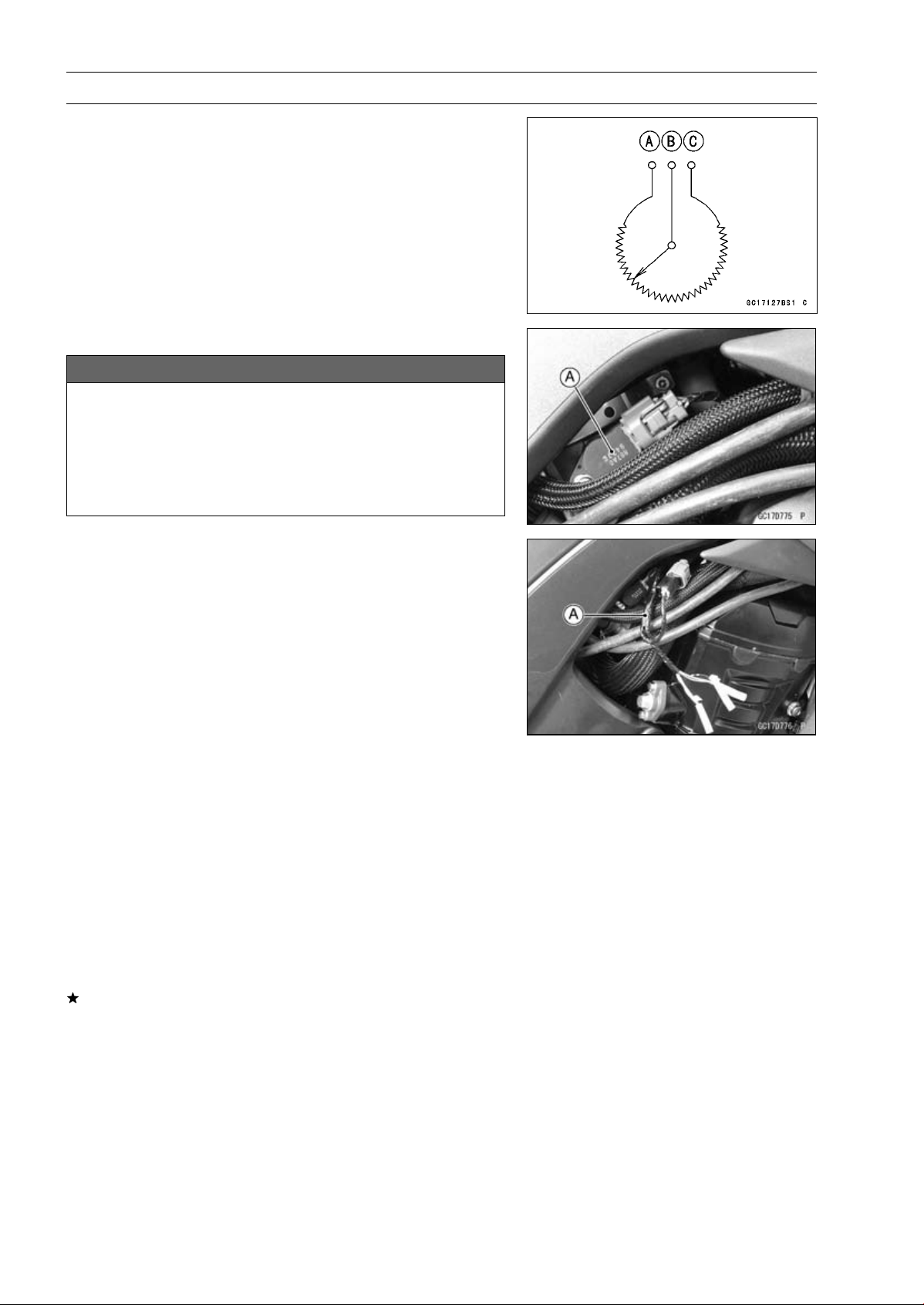
3-72 FUEL SYSTEM (DFI)
Subthrottle Sensor (Service Code 32)
The subthrottle sensor is a rotating variable resistor that
change output voltage according to throttle operating. The
ECU senses this voltage change and determines fuel injec-
tion quantity, and ignition timing according to engine rpm,
and throttle opening.
Input Terminal [A]
Output Terminal [B]
Ground Terminal [C]
Subthrottle Sensor Removal/Adjustment
NOTICE
Do not remove or adjust the subthrottle sensor [A]
since it has been adjusted and set with precision at
the factory.
Never drop the throttle body assy especially on a
hard surface. Such a shock to the subthrottle sen-
sor can damage it.
Subthrottle Sensor Input Voltage Inspection
NOTE
○
Be sure the battery is fully charged.
•
Turn the ignition switch OFF.
•
Disconnect the subthrottle sensor and connect the har-
ness adapter [A] between these connectors.
Special Tool - Throttle Sensor Setting Adapter: 57001
-1538
•
Connect a digital meter to the harness adapter leads.
Subthrottle Sensor Input Voltage
Connections to Adapter:
Digital Meter (+) W (sensor BL) lead
Digital Meter (–) BK (sensor BR/BK) lead
•
Measure the input voltage with the engine stopped and
with the connector joined.
•
Turn the ignition switch ON.
Input Voltage
Standard: DC 4.75
∼ 5.25 V
•
Turn the ignition switch OFF.
If the reading is within the standard, check the output volt-
age (see Subthrottle Sensor Output Voltage Inspection).
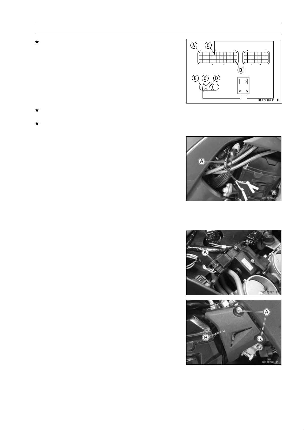
FUEL SYSTEM (DFI) 3-73
Subthrottle Sensor (Service Code 32)
If the reading is out of the standard, remove the ECU
and check the wiring for continuity between main harness
connectors.
○
Disconnect the ECU and sensor connectors.
Wiring Inspection
ECU Connector [A]
Subthrottle Sensor Connector [B]
BL lead (ECU terminal 5) [C]
BR/BK lead (ECU terminal 33) [D]
If the wiring is good, check the ECU for its ground and
power supply (see ECU Power Supply Inspection).
If the ground and power supply are good, replace the ECU
(see ECU Removal/Installation).
Subthrottle Sensor Output Voltage Inspection
•
Measure the output voltage at the subthrottle sensor in
the same way as input voltage inspection, note the fol-
lowing.
○
Disconnect the subthrottle sensor connector and connect
the harness adapter [A] between these connectors.
Special Tool - Throttle Sensor Setting Adapter: 57001
-1538
Subthrottle Sensor Output Voltage
Connections to Adapter:
Digital Meter (+) R (sensor BR) lead
Digital Meter (–) BK (sensor BR/BK) lead
•
Remove the air cleaner housing (see Air Cleaner Housing
Removal).
•
Disconnect the subthrottle valve actuator harness con-
nector [A].
•
Remove:
Bolts [A]
Throttle Pulley Cover [B]
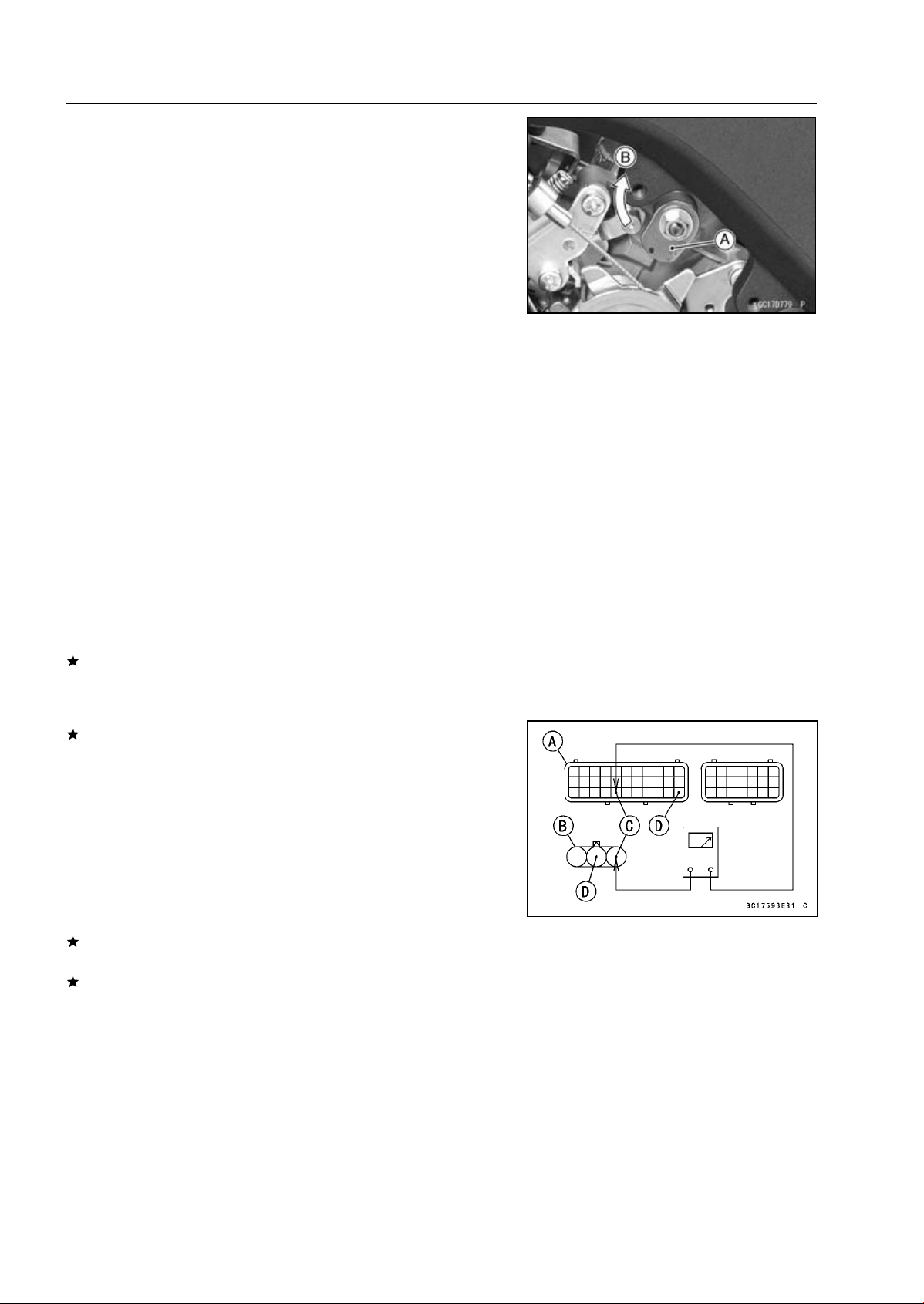
3-74 FUEL SYSTEM (DFI)
Subthrottle Sensor (Service Code 32)
•
Measure the output voltage with the engine stopped with
the connector joined.
•
Turn the ignition switch ON.
•
Measure the output voltage when the subthrottle valve is
completely closed by turning the lever [A] fully clockwise
[B].
Output Voltage
Standard: DC 1.08
∼ 1.12 V at subthrottle valve full
close position
DC 4.2
∼ 4.4 V at subthrottle valve full open
position (for reference)
NOTE
○
Turn the lever counterclockwise, confirm the output volt-
age will be raise.
○
The standard voltage refers to the value when the volt-
age reading at the Input Voltage Inspection shows 5 V
exactly.
○
When the input voltage reading shows other than 5 V,
derive a voltage range as follows.
Example:
In the case of a input voltage of 4.75 V.
1.08 × 4.75 ÷ 5.00 = 1.03 V
1.12 × 4.75 ÷ 5.00 = 1.06 V
Thus, the valid range is 1.03
∼
1.06 V
•
Turn the ignition switch OFF.
If the reading is out of the standard, check the subthrot-
tle sensor resistance (see Subthrottle Sensor Resistance
Inspection).
If the reading is within the standard, remove the ECU and
check the wiring for continuity between main harness con-
nectors.
○
Disconnect the ECU and sensor connectors.
Wiring Inspection
ECU Connector [A]
Subthrottle Sensor Connector [B]
BR lead (ECU terminal 27) [C]
BR/BK lead (ECU terminal 33) [D]
If the wiring is good, check the ECU for its ground and
power supply (see ECU Power Supply Inspection).
If the ground and power supply are good, replace the ECU
(see ECU Removal/Installation).
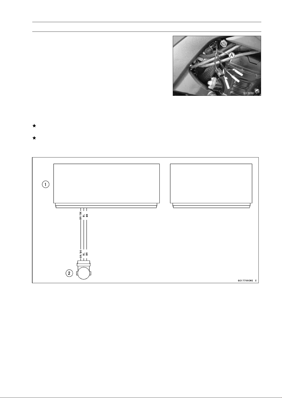
FUEL SYSTEM (DFI) 3-75
Subthrottle Sensor (Service Code 32)
Subthrottle Sensor Resistance Inspection
•
Turn the ignition switch OFF.
•
Disconnect the subthrottle sensor connector.
○
Disconnect the subthrottle sensor connector and connect
the harness adapter [A] to the sensor connector only.
Special Tool - Throttle Sensor Setting Adapter: 57001
-1538
Subthrottle Sensor Output Resistance
Connections to Adapter:
Digital Meter (+) W (sensor BL) lead
Digital Meter (–) BK (sensor BR/BK) lead
Standard: 4
∼ 6k
If the reading is out of the standard, replace the throttle
body assy.
If the reading is within the standard, but the problem still
exists, replace the ECU (see ECU Removal/Installation).
Subthrottle Sensor Circuit
1. ECU
2. Subthrottle Sensor

3-76 FUEL SYSTEM (DFI)
Oxygen Sensor - not activated (Service Code 33, Equipped Models)
Oxygen Sensor Removal/Installation
•
Refer to the Oxygen Sensor Removal/Installation in the
Electrical System chapter.
Oxygen Sensor Inspection
•
Warm up the engine thoroughly until the radiator fan
starts.
•
Turn the ignition switch OFF.
•
Open the clamp [A], and pull out the oxygen sensor lead
connector [B].
•
Disconnect the oxygen sensor lead connector (4 pins
connector) and connect the harness adapter [A] between
these connectors.
[B] Main Harness
[C] Oxygen Sensor
Special Tool - Measuring Adapter: 57001-1700
•
Connect a digital meter [D] to the harness adapter leads.
Oxygen Sensor Output Voltage
Connections to Adapter:
Digital Meter (+) R (sensor BL) lead
Digital Meter () BK (sensor W) lead
•
Remove:
Air Cleaner Housing (see Air Cleaner Housing Removal)
•
Disconnect the stick coil connectors [A].
•
Turn over the rubber plate [B].
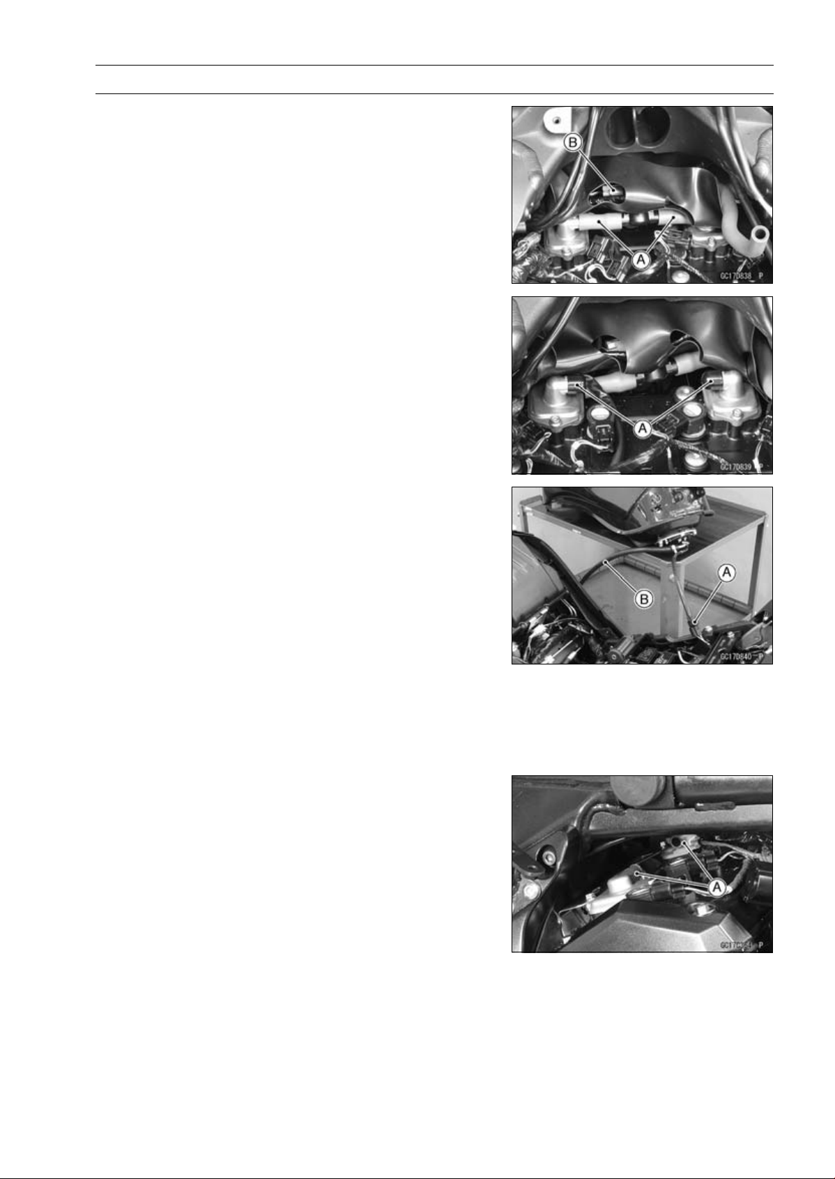
FUEL SYSTEM (DFI) 3-77
Oxygen Sensor - not activated (Service Code 33, Equipped Models)
•
Separate the air switching valve hoses [A] from the air
suction valve covers.
○
Do not disconnect the air switching valve connector [B].
•
Install the suitable plugs [A] on the fitting of the air suction
valve covers, and shut off the secondary air.
•
Connect the stick coil connectors.
•
Install the air cleaner housing temporarily (see Air Cleaner
Housing Installation).
•
Remove the fuel hose (see Fuel Tank Removal).
•
Connect the following parts temporary.
Fuel Pump Lead Connector [A]
Fuel Hose [B]
Special Tool - Fuel Hose: 57001-1607
•
Start the engine, and let it idle.
•
Measure the output voltage with the connector joined.
Output Voltage (with Plugs)
Standard: DC 0.7 V or more
•
Next, remove the air cleaner housing to take out the plugs
from the fittings [A] of the air suction valve covers.
•
Install the air cleaner housing.
•
Start the engine, and let it idle.
•
Measure the output voltage with the connector joined.
Output Voltage (without Plugs)
Standard: DC 0.2 V or less
•
Turn the ignition switch OFF.
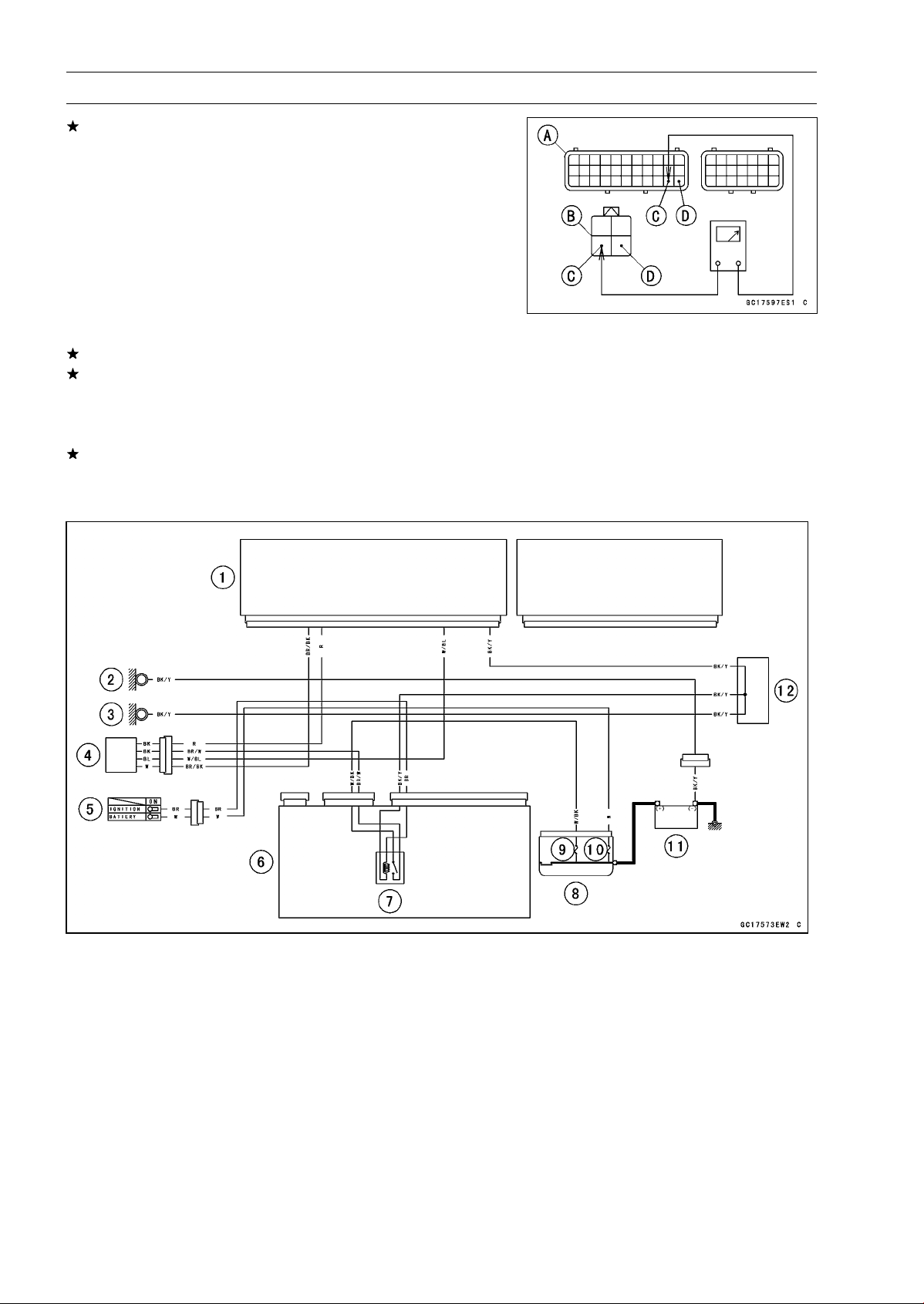
3-78 FUEL SYSTEM (DFI)
Oxygen Sensor - not activated (Service Code 33, Equipped Models)
If the reading is out of the standard (with plugs: DC 0.7
V or more, without plugs: DC 0.2 V or less), remove the
ECU and check the wiring for continuity between main
harness connectors.
○
Disconnect the ECU and sensor connectors.
Wiring Inspection
ECU Connectors [A]
Oxygen Sensor Connector [B]
W/BL lead (ECU terminal 32) [C]
BR/BK lead (ECU terminal 33) [D]
If the wiring is good, replace the sensor.
If the reading is within the standard (with plugs: DC 0.7 V
or more, without plugs: DC 0.2 V or less), check the ECU
for its ground and power supply (see ECU Power Supply
Inspection).
If the ground and power supply are good, replace the ECU
(see ECU Removal/Installation).
Oxygen Sensor Circuit
1. ECU
2. Frame Ground
3. Meter Ground
4. Oxygen Sensor
5. Ignition Switch
6. Relay Box
7. ECU Main Relay
8. Starter Relay
9. FI Fuse 15 A
10. Main Fuse 30 A
11. Battery 12 V 8 Ah
12. Water-proof Joint C
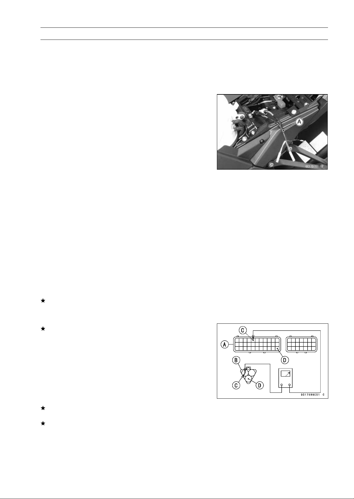
FUEL SYSTEM (DFI) 3-79
Exhaust Butterfly Valve Actuator Sensor (Service Code 34)
Exhaust Butterfly Valve Actuator Sensor
Removal/Installation
The exhaust butterfly valve actuator sensor is built in the
exhaust butterfly valve actuator. So, the sensor itself can
not be removed. Remove the exhaust butterfly valve actu-
ator (see Exhaust Butterfly Valve Actuator Removal).
Exhaust Butterfly Valve Actuator Sensor Input
Voltage Inspection
NOTE
○
Be sure the battery is fully charged.
•
Turn the ignition switch OFF.
•
Remove the left side cover (see Side Cover Removal in
the Frame chapter).
•
Disconnect the exhaust butterfly valve actuator sensor
lead connector (3 pins connector) and connect the har-
ness adapter [A] between these connector.
Special Tool - Throttle Sensor Setting Adapter #1: 57001
-1400
•
Connect a digital meter to the harness adapter leads.
Exhaust Butterfly Valve Actuator Sensor Input Voltage
Connections to Adapter:
Digital Meter (+) Y/W (actuator W) lead
Digital Meter () BK/BL (actuator BK) lead
•
Measure the input voltage with the engine stopped and
with the connector joined.
•
Turn the ignition switch ON.
Input Voltage
Standard: DC 4.75
∼ 5.25 V
•
Turn the ignition switch OFF.
If the reading is within the standard, check the output volt-
age (see Exhaust Butterfly Valve Actuator Sensor Output
Voltage Inspection).
If the reading is out of the standard, remove the ECU
and check the wiring for continuity between main harness
connectors.
○
Disconnect the ECU and sensor connectors.
Wiring Inspection
ECU Connector [A]
Exhaust Butterfly Valve Actuator Sensor Connector [B]
BL lead (ECU terminal 5) [C]
BR/BK lead (ECU terminal 33) [D]
If the wiring is good, check the ECU for its ground and
power supply (see ECU Power Supply Inspection).
If the ground and power supply are good, replace the ECU
(see ECU Removal/Installation).
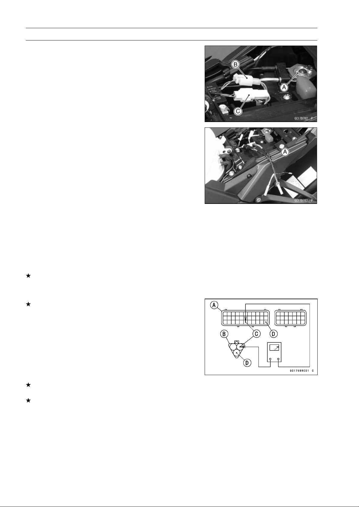
3-80 FUEL SYSTEM (DFI)
Exhaust Butterfly Valve Actuator Sensor (Service Code 34)
Exhaust Butterfly Valve Actuator Sensor Output
Voltage Inspection
NOTE
○
Before this inspection, confirm the pulley [A] is original
position (see Exhaust Butterfly Valve Actuator Installa-
tion).
•
Disconnect:
2 pins Connector [B]
3 pins Connector [C]
•
Connect the harness adapter [A] between the 3 pins con-
nectors.
Special Tool - Throttle Sensor Setting Adapter #1: 57001
-1400
•
Connect a digital meter to the harness adapter leads.
Exhaust Butterfly Valve Actuator Sensor Output Voltage
Connections to Adapter:
Digital Meter (+) BL (actuator Y) lead
Digital Meter () BK/BL (actuator BK) lead
•
Measure the output voltage at the 3 pins connector of the
exhaust butterfly valve actuator when the pulley is original
position.
•
Turn the ignition switch ON.
Output Voltage
Standard: DC 3.46
∼ 3.76 V at pulley original position
•
Turn the ignition switch OFF.
If the reading is out of the standard, check the exhaust
butterfly valve actuator sensor resistance (see Exhaust
Butterfly Valve Actuator Sensor Resistance Inspection).
If the reading is within the standard, remove the ECU and
check the wiring for continuity between main harness con-
nectors.
○
Disconnect the ECU and sensor connectors.
Wiring Inspection
ECU Connector [A]
Exhaust Butterfly Valve Actuator Sensor Connector [B]
R/BK lead (ECU terminal 28) [C]
BR/BK lead (ECU terminal 33) [D]
If the wiring is good, check the ECU for its ground and
power supply (see ECU Power Supply Inspection).
If the ground and power supply are good, replace the ECU
(see ECU Removal/Installation).
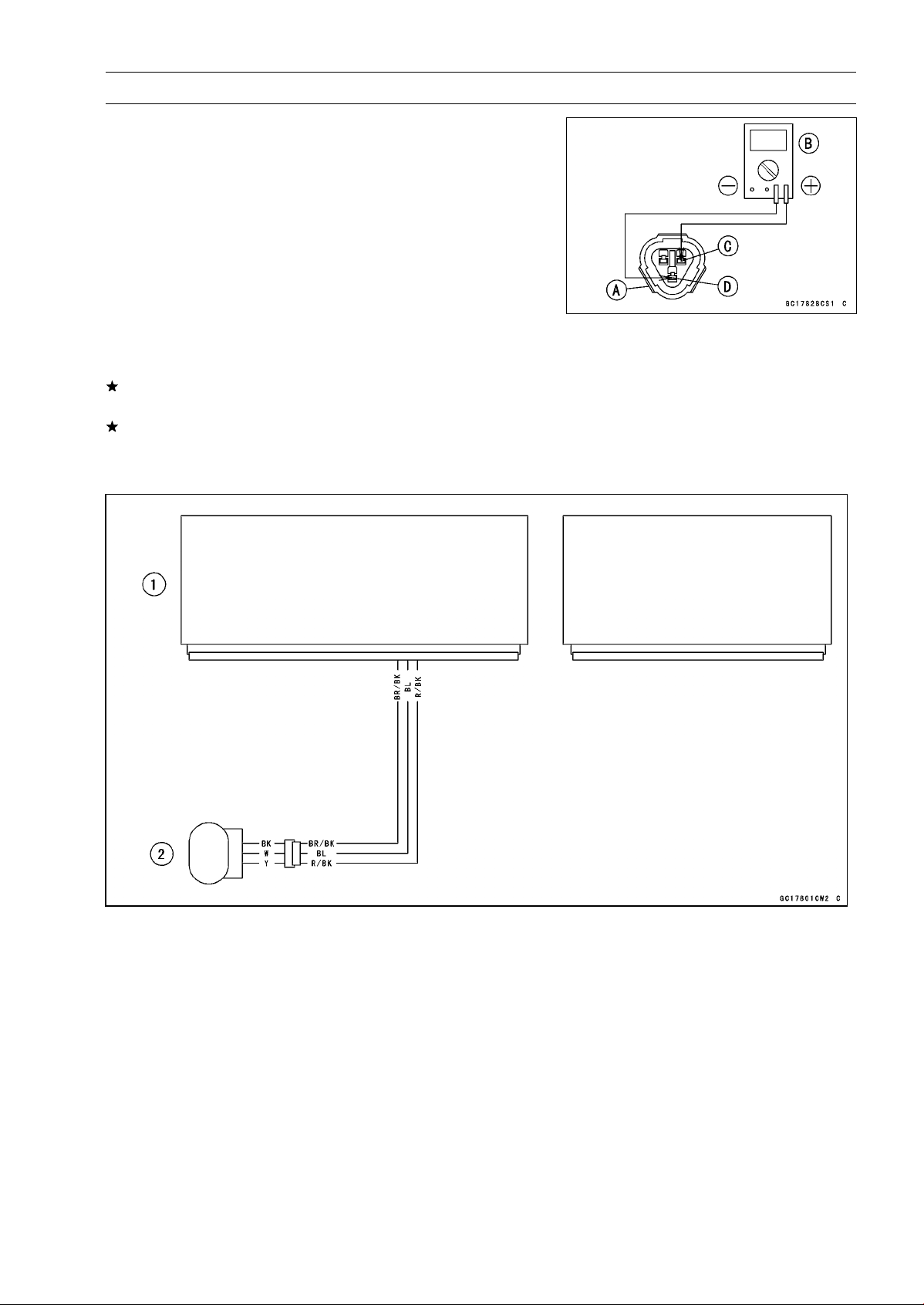
FUEL SYSTEM (DFI) 3-81
Exhaust Butterfly Valve Actuator Sensor (Service Code 34)
Exhaust Butterfly Valve Actuator Sensor
Resistance Inspection
•
Turn the ignition switch OFF.
•
Disconnect the exhaust butterfly valve actuator sensor
connector (3 pins connector) [A].
•
Connect a digital meter [B] to the exhaust butterfly valve
actuator sensor connector.
•
Measure the exhaust butterfly valve actuator sensor re-
sistance.
Exhaust Butterfly Valve Actuator Sensor Resistance
Connections: W lead [C] BK lead [D]
Standard: 4
∼ 6k
If the reading is out of the standard, replace the exhaust
butterfly valve actuator.
If the reading within the standard, but the problem still
exists, replace the ECU (see ECU Removal/Installation).
Exhaust Butterfly Valve Actuator Sensor Circuit
1. ECU
2. Exhaust Butterfly Valve Actuator
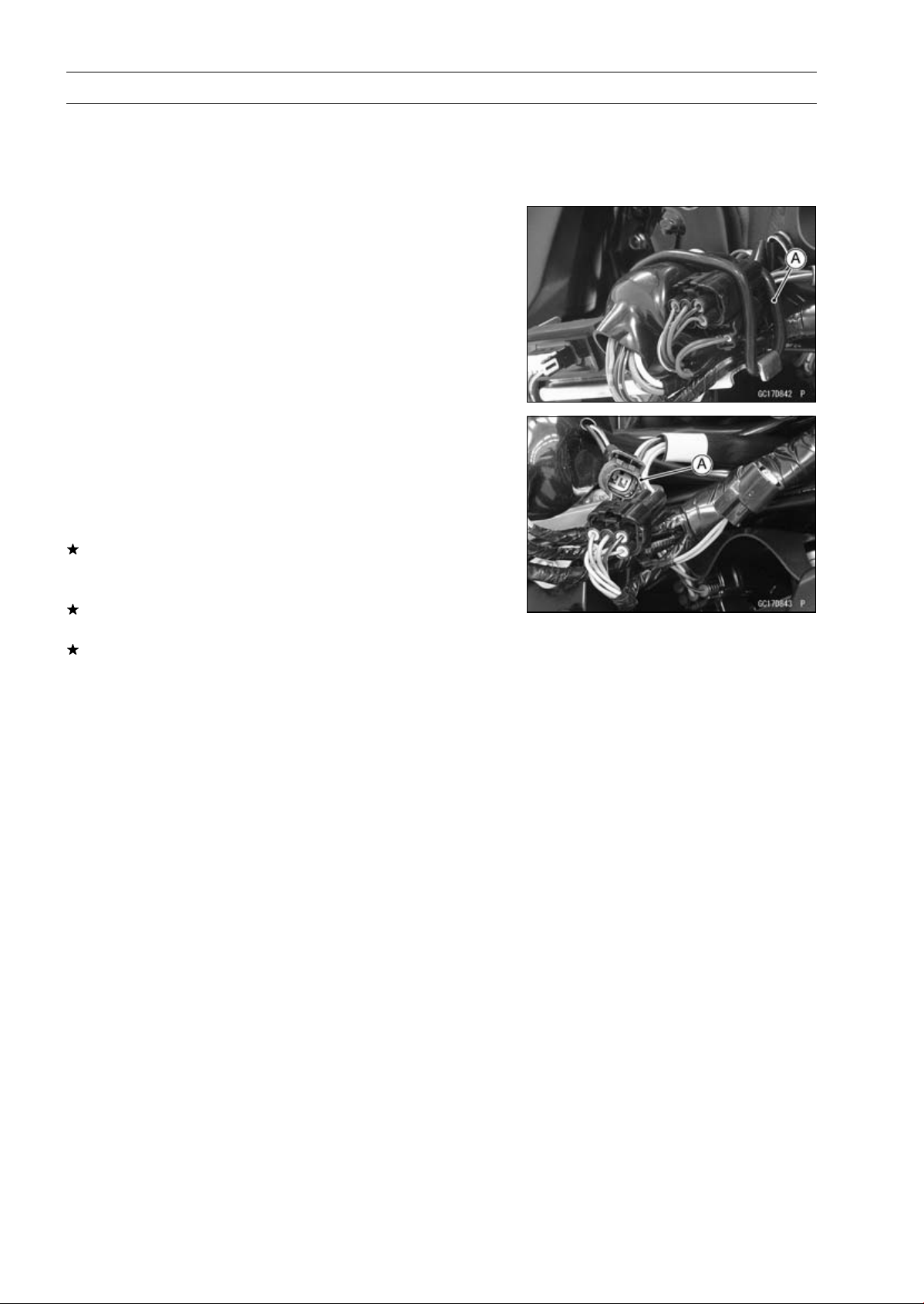
3-82 FUEL SYSTEM (DFI)
Immobilizer Amplifier (Service Code 35, Equipped Models)
Antenna Resistance Inspection
•
Turn the ignition switch OFF.
•
Remove the left center fairing (see Center Fairing Re-
moval in the Frame chapter).
•
Remove the band [A].
•
Disconnect the antenna lead connector [A].
•
Measure the antenna resistance.
Antenna Resistance
Connections: BK lead BK/W lead
Standard: About 3.0
∼ 4.6
If the reading is out of the standard, replace the antenna
(see Immobilizer System Parts Replacement in the Elec-
trical System chapter).
If the reading is within the standard, check the wiring to
the amplifier (see wiring diagram in next section).
If the wiring is good, check the input voltage of the ampli-
fier (see Amplifier Input Voltage Inspection).
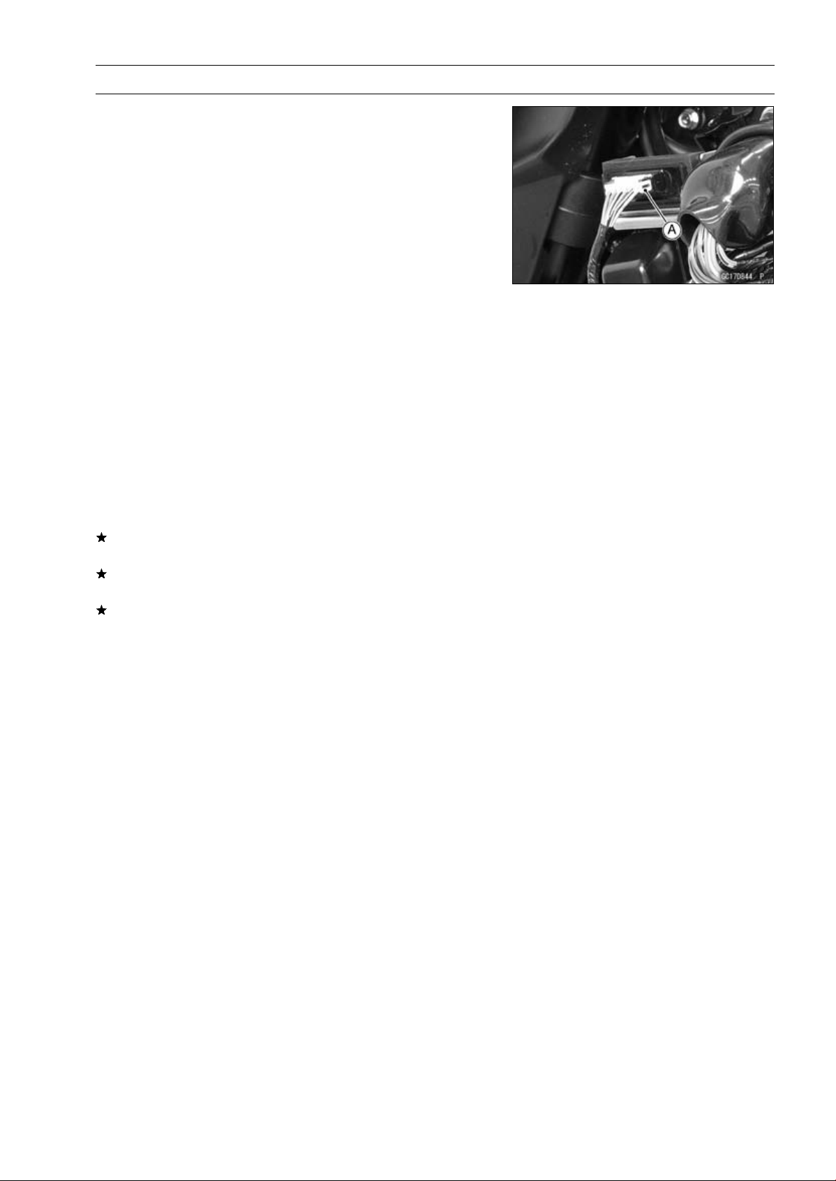
FUEL SYSTEM (DFI) 3-83
Immobilizer Amplifier (Service Code 35, Equipped Models)
Amplifier Input Voltage Inspection
NOTE
○
Be sure the battery is fully charged.
•
Turn the ignition switch OFF.
•
Remove the left center fairing (see Center Fairing Re-
moval in the Frame chapter).
○
Do not disconnect the connectors.
•
Connect a digital meter to the amplifier connector [A] with
needle adapter set.
Special Tool - Needle Adapter Set: 57001-1457
Amplifier Input Voltage
Connections to Amplifier Connector:
Digital Meter (+) BR/W lead
Digital Meter (–) BK/Y lead
•
Measure the input voltage with the engine stopped and
with the connector joined.
•
Turn the ignition switch ON.
Input Voltage
Standard: Battery Voltage
•
Turn the ignition switch OFF.
If the reading is out of the standard, check the wiring (see
wiring diagram in next section).
If the reading is within the standard, check the wiring to
ECU (see wiring diagram in next section).
If the wiring is good, replace the amplifier (see Immobi-
lizer System Parts Replacement in the Electrical System
chapter).
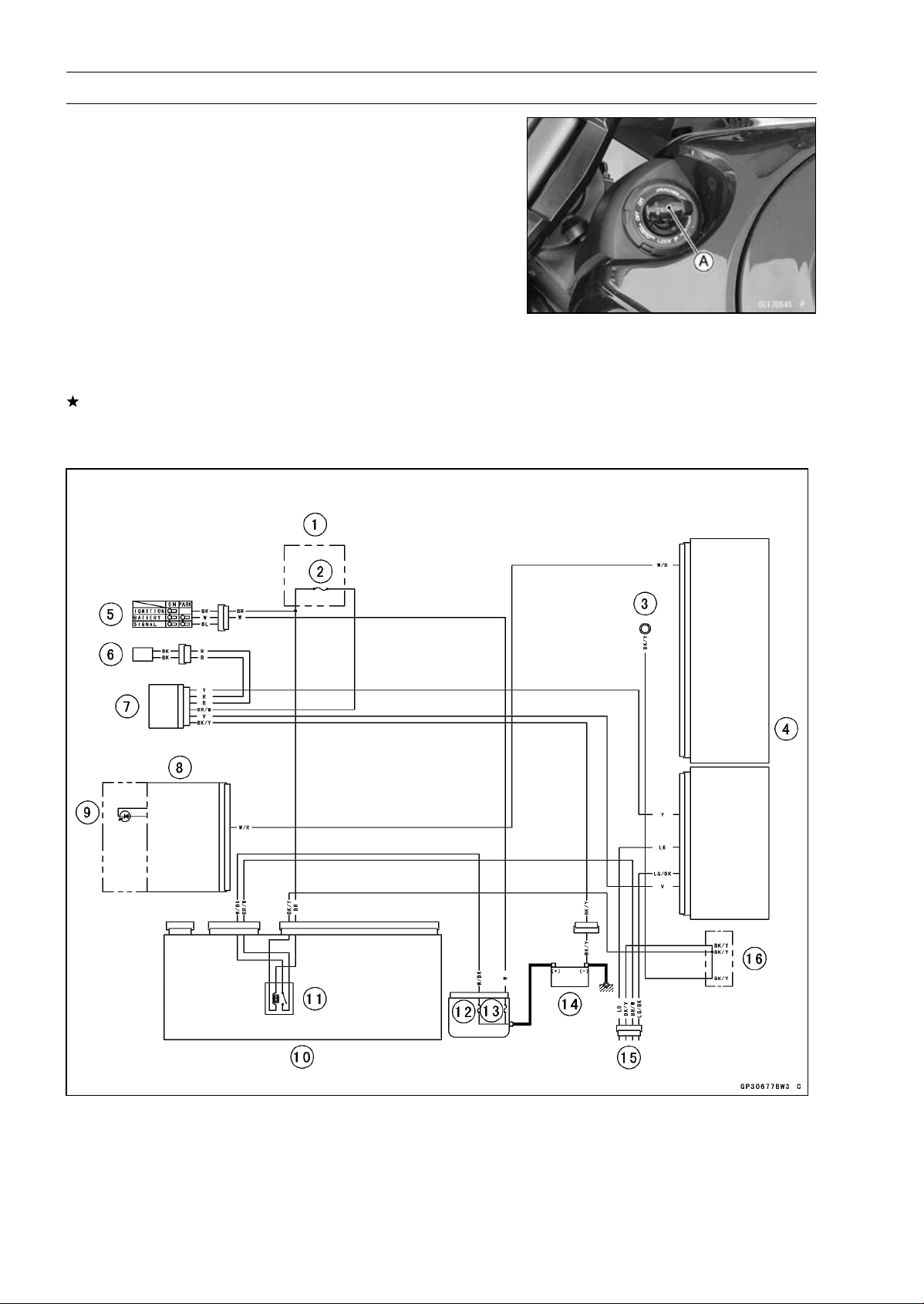
3-84 FUEL SYSTEM (DFI)
Blank Key Detection (Service Code 36, Equipped Models)
The master key exists in ZR1000DA/EA only.
•
This code appears in the following conditions.
○
The transponder [A] in the master and/or user key (ignition
key) is malfunction.
○
When the spare key of unregistration is used.
○
When the master key is registered in the registered ECU.
•
Therefore, the service code 36 will disappear when the
above issue is solved.
User Key (Ignition Key) Inspection
•
Register the user key (ignition key) correctly (see Key
Registration in the Electrical System chapter).
If the service code 36 appears again, the transponder in
the key is malfunction, replace it.
Immobilizer System Circuit
1. Fuse Box
2. Ignition Fuse 15 A
3. Meter Ground
4. ECU
5. Ignition Switch
6. Immobilizer Antenna
7. Immobilizer Amplifier
8. Meter Unit
9. Oil Pressure/FI/Immobi-
lizer Warning Indicator
Light (LED)
10. Relay Box
11. ECU Main Relay
12. FI Fuse 15 A
13. Main Fuse 30 A
14. Battery 12 V 8 Ah
15. Immobilizer/Kawasaki Diag-
nostic System Connector
16. Water-proof Joint C
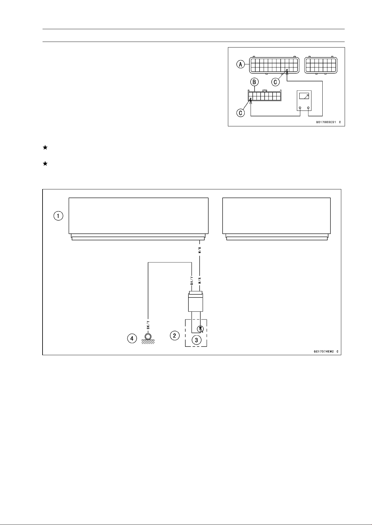
FUEL SYSTEM (DFI) 3-85
ECU Communication Error (Service Code 39)
ECU Communication Line Inspection
○
When the data is not sent from the ECU to the meter unit
for more than about 10 seconds, the service code 39 is
displayed.
○
The service code 39 is detected with meter unit.
•
Remove the ECU and meter unit, check the wiring for
continuity between main harness connector.
○
Disconnect the ECU and meter unit connectors.
Wiring Inspection
ECU Connector [A] Meter Unit Connector [B]
W/R lead (ECU terminal 31) [C]
If the wiring is good, check the meter unit (see Meter Unit
Inspection in the Electrical System chapter).
If the meter unit is normal, replace the ECU (see ECU
Removal/Installation).
ECU Communication Line Circuit
1. ECU
2. Meter Unit
3. Warning Indicator Light (LED)
4. Meter Ground
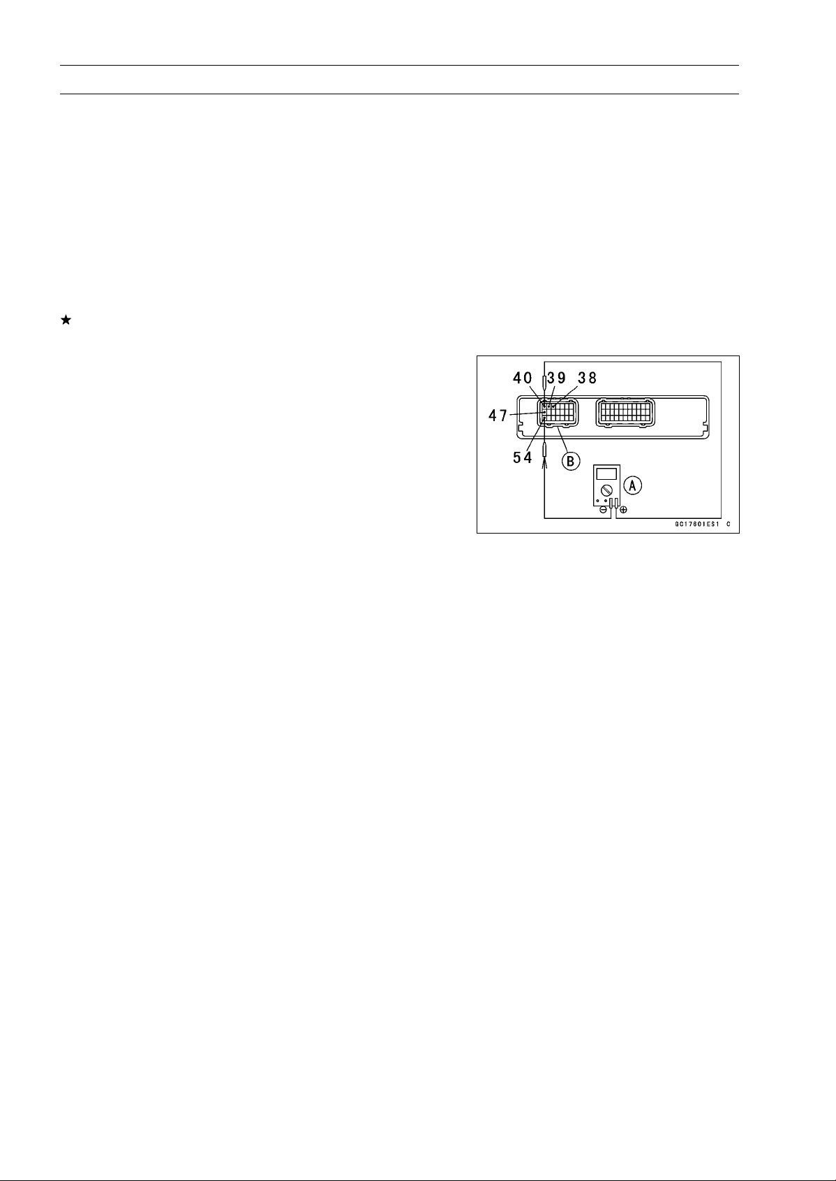
3-86 FUEL SYSTEM (DFI)
Stick Coils #1, #2, #3, #4 (Service Code 51, 52, 53, 54)
Stick Coil #1: Service Code 51
Stick Coil #2: Service Code 52
Stick Coil #3: Service Code 53
Stick Coil #4: Service Code 54
Stick Coil Removal/Installation
•
Refer to the Stick Coil Removal/Installation in the Electri-
cal System chapter.
Stick Coil Primary Winding Resistance Inspection
•
Refer to the Stick Coil Inspection in the Electrical System
chapter.
If the reading is within the standard, check the input volt-
age (see Stick Coil Input Voltage Inspection).
Stick Coil Input Voltage Inspection
NOTE
○
Be sure the battery is fully charged.
•
Turn the ignition switch OFF.
•
Remove the ECU (see ECU Removal).
○
Do not disconnect the ECU connectors.
•
Connect a digital meter [A] to the connector [B] with the
needle adapter set.
Special Tool - Needle Adapter Set: 57001-1457
Stick Coil Input Voltage
Connections to ECU Connector:
For Stick Coil #1
Digital Meter (+) BK lead (terminal 40)
Digital Meter (–) BK/Y lead (terminal 54)
For Stick Coil #2
Digital Meter (+) R/W lead (terminal 47)
Digital Meter (–) BK/Y lead (terminal 54)
For Stick Coil #3
Digital Meter (+) BK/W lead (terminal 39)
Digital Meter (–) BK/Y lead (terminal 54)
For Stick Coil #4
Digital Meter (+) BK/O lead (terminal 38)
Digital Meter (–) BK/Y lead (terminal 54)
•
Measure the input voltage to each primary winding of the
stick coils with the engine stopped and with the connec-
tors joined.
•
Turn the engine stop switch to run position.
•
Turn the ignition switch ON.
Input Voltage
Standard:
Battery Voltage
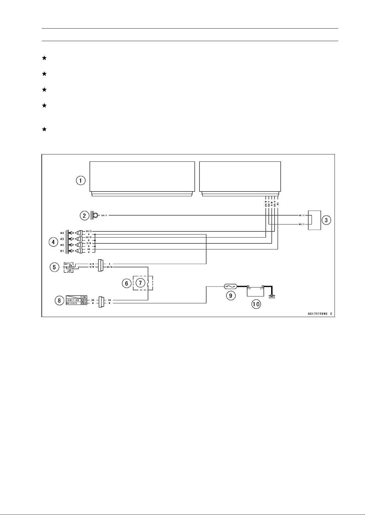
FUEL SYSTEM (DFI) 3-87
Stick Coils #1, #2, #3, #4 (Service Code 51, 52, 53, 54)
•
Turn the ignition switch OFF.
If the input voltage is out of the standard, check the wiring
for continuity (see wiring diagram in this section).
If the wiring is good, check the ECU for its ground and
power supply (see ECU Power Supply Inspection).
If the ground and power supply are good, replace the ECU
(see ECU Removal/Installation).
If the input voltage is within the standard, check the ECU
for its ground and power supply (see ECU Power Supply
Inspection).
If the ground and power supply are good, replace the ECU
(see ECU Removal/Installation).
Stick Coil Circuit
1. ECU
2. Meter Ground
3. Water-proof Joint C
4. Stick Coil #1, #2, #3, #4
5. Engine Stop Switch
6. Fuse Box
7. Ignition Fuse 15 A
8. Ignition Switch
9. Main Fuse 30 A
10. Battery 12 V 8 Ah
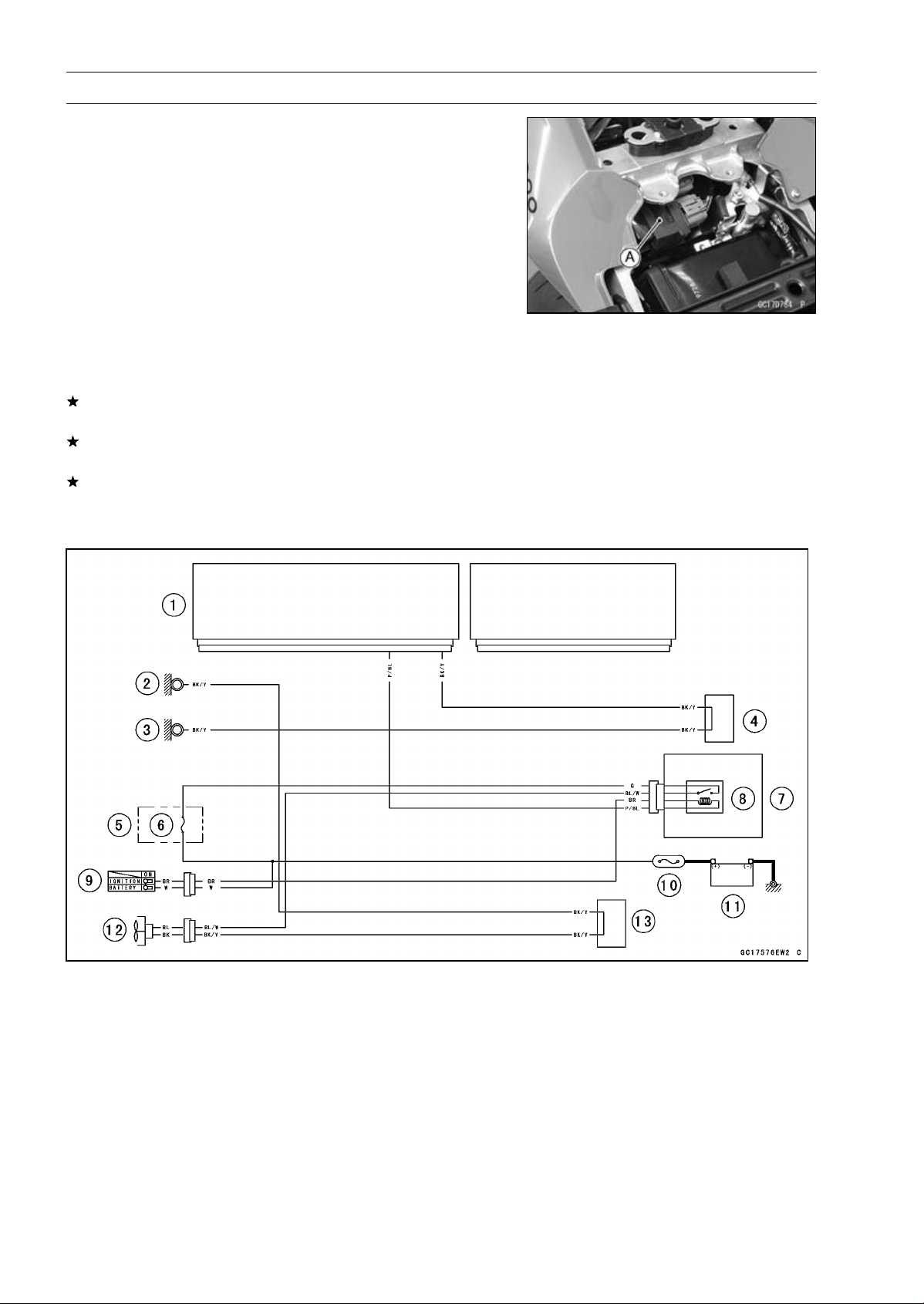
3-88 FUEL SYSTEM (DFI)
Radiator Fan Relay (Service Code 56)
Radiator Fan Relay Removal/Installation
○
The radiator fan relay is built in the relay box [A].
•
Refer to the Relay Box Removal in the Electrical System
chapter.
Radiator Fan Relay Inspection
•
Refer to the Relay Circuit Inspection in the Electrical Sys-
tem chapter.
If the radiator fan relay is normal, check the wiring for
continuity (see wiring diagram in this section).
If the wiring is good, check the ECU for its ground and
power supply (see ECU Power Supply Inspection).
If the ground and power supply are good, replace the ECU
(see ECU Removal/Installation).
Radiator Fan Relay Circuit
1. ECU
2. Frame Ground
3. Meter Ground
4. Water-proof Joint C
5. Fuse Box
6. Fan Fuse 15 A
7. Relay Box
8. Radiator Fan Relay
9. Ignition Switch
10. Main Fuse 30 A
11. Battery 12 V 8 Ah
12. Radiator Fan Motor
13. Water-proof Joint A
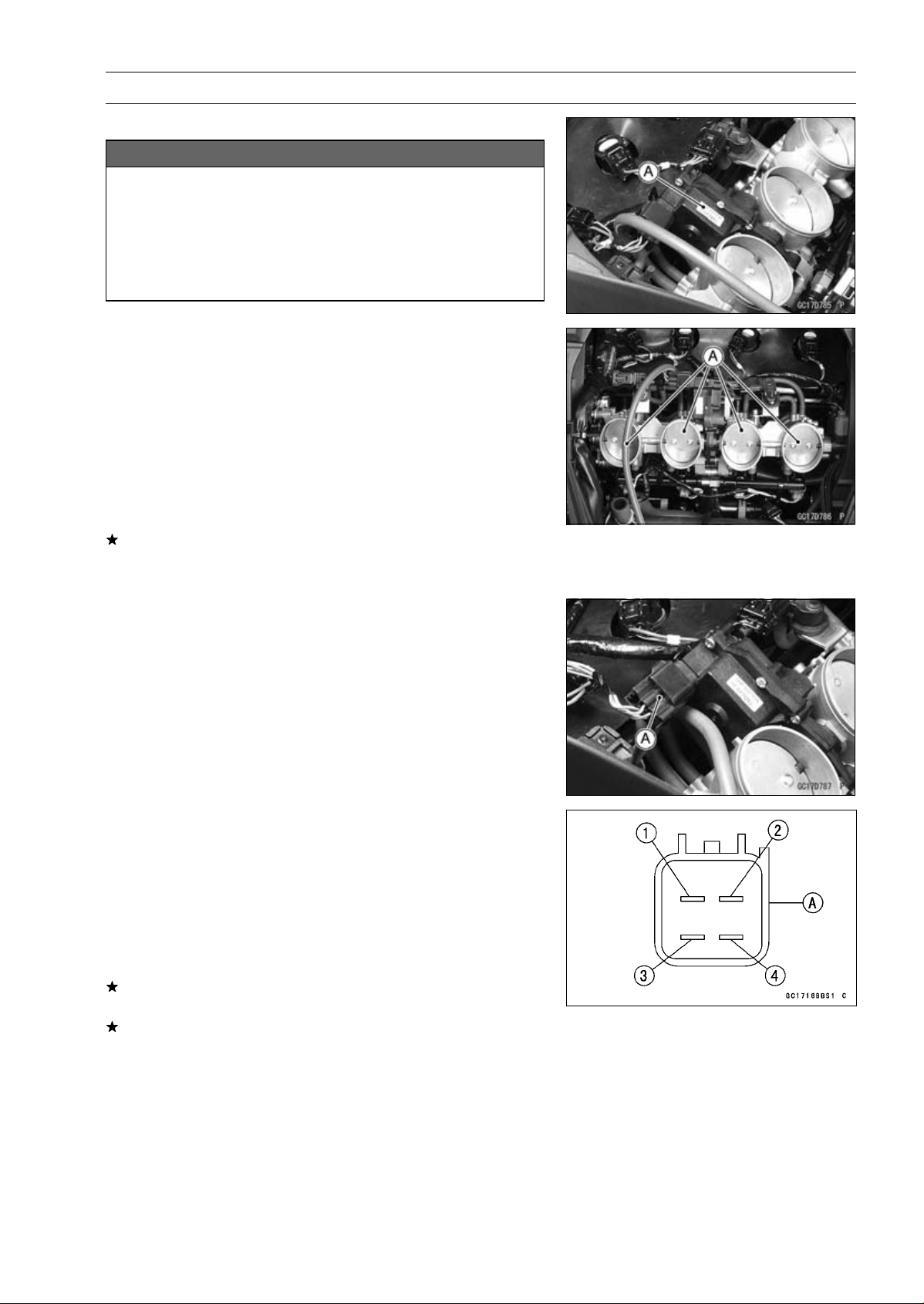
FUEL SYSTEM (DFI) 3-89
Subthrottle Valve Actuator (Service Code 62)
Subthrottle Valve Actuator Removal
NOTICE
Do not remove the subthrottle valve actuator [A]
since it has been adjusted and set with precision
at the factory.
Never drop the throttle body assy especially on a
hard surface. Such a shock to the subthrottle valve
actuator can damage it.
Subthrottle Valve Actuator Inspection
NOTE
○
Be sure the battery is fully charged.
•
Remove the air cleaner housing (see Air Cleaner Housing
Removal).
•
Turn the ignition switch ON.
•
Check to see that all the subthrottle valves [A] open and
close smoothly.
•
Turn the ignition switch OFF.
If the subthrottle valves do not operate, check the sub-
throttle valve actuator resistance (see Subthrottle Valve
Actuator Resistance Inspection).
Subthrottle Valve Actuator Resistance Inspection
•
Turn the ignition switch OFF.
•
Disconnect the subthrottle valve actuator connector [A].
•
Connect a digital meter to the subthrottle valve actuator
connector [A].
•
Measure the subthrottle valve actuator resistance.
Subthrottle Valve Actuator Resistance
Connections: LG/R lead [1] P/BL lead [2]
G lead [3] W/BL lead [4]
Standard: About 5.2
∼ 7.8
If the reading is out of the standard, replace the throttle
body assy.
If the reading is within the standard, check the input volt-
age (see Subthrottle Valve Actuator Input Voltage Inspec-
tion).
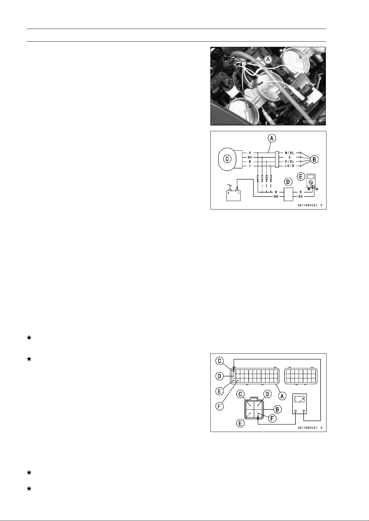
3-90 FUEL SYSTEM (DFI)
Subthrottle Valve Actuator (Service Code 62)
Subthrottle Valve Actuator Input Voltage
Inspection
NOTE
○
Be sure the battery is fully charged.
•
Turn the ignition switch OFF.
•
Disconnect the subthrottle valve actuator connector and
connect the harness adapter [A] between these connec-
tors as shown in the figure.
Main Harness [B]
Subthrottle Valve Actuator [C]
Special Tool - Measuring Adapter: 57001-1700
•
Connect the peak voltage adapter [D] and a digital meter
[E] to the harness adapter leads.
Special Tool - Peak Voltage Adapter: 57001-1415
Type: KEK-54-9-B
Subthrottle Valve Actuator Input Voltage
Connections to Adapter:
(I) Digital Meter (+) R (actuator W/BL) lead
Digital Meter (–) Battery (–) terminal
(II) Digital Meter (+) BK (actuator G) lead
Digital Meter (–) Battery (–) terminal
(III) Digital Meter (+) W (actuator P/BL) lead
Digital Meter (–) Battery (–) terminal
(IV) Digital Meter (+) Y (actuator LG/R) lead
Digital Meter (–) Battery (–) terminal
•
Measure the actuator input voltage with the engine
stopped and with the connector joined.
•
Turn the ignition switch ON.
Input Voltage
Standard: About DC 11.5
∼ 13.5 V
•
Turn the ignition switch OFF.
If the reading is in specification, but the actuator does not
operate, replace the throttle body assy.
If the reading is out of the specification, remove the ECU
and check the wiring for continuity between main harness
connector.
Special Tool - Hand Tester: 57001-1394
○
Disconnect the ECU and actuator connectors.
Wiring Continuity Inspection
ECU Connector [A]
Subthrottle Valve Actuator Connector [B]
LG/R lead (ECU terminal 1) [C]
P/BL lead (ECU terminal 12) [D]
G lead (ECU terminal 23) [E]
W/BL lead (ECU terminal 24) [F]
If the wiring is good, check the ECU for its ground and
power supply (see ECU Power Supply Inspection).
If the ground and power supply are good, replace the ECU
(see ECU Removal/Installation).
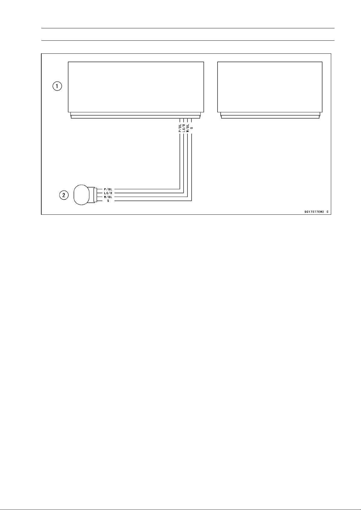
FUEL SYSTEM (DFI) 3-91
Subthrottle Valve Actuator (Service Code 62)
Subthrottle Valve Actuator Circuit
1. ECU
2. Subthrottle Valve Actuator
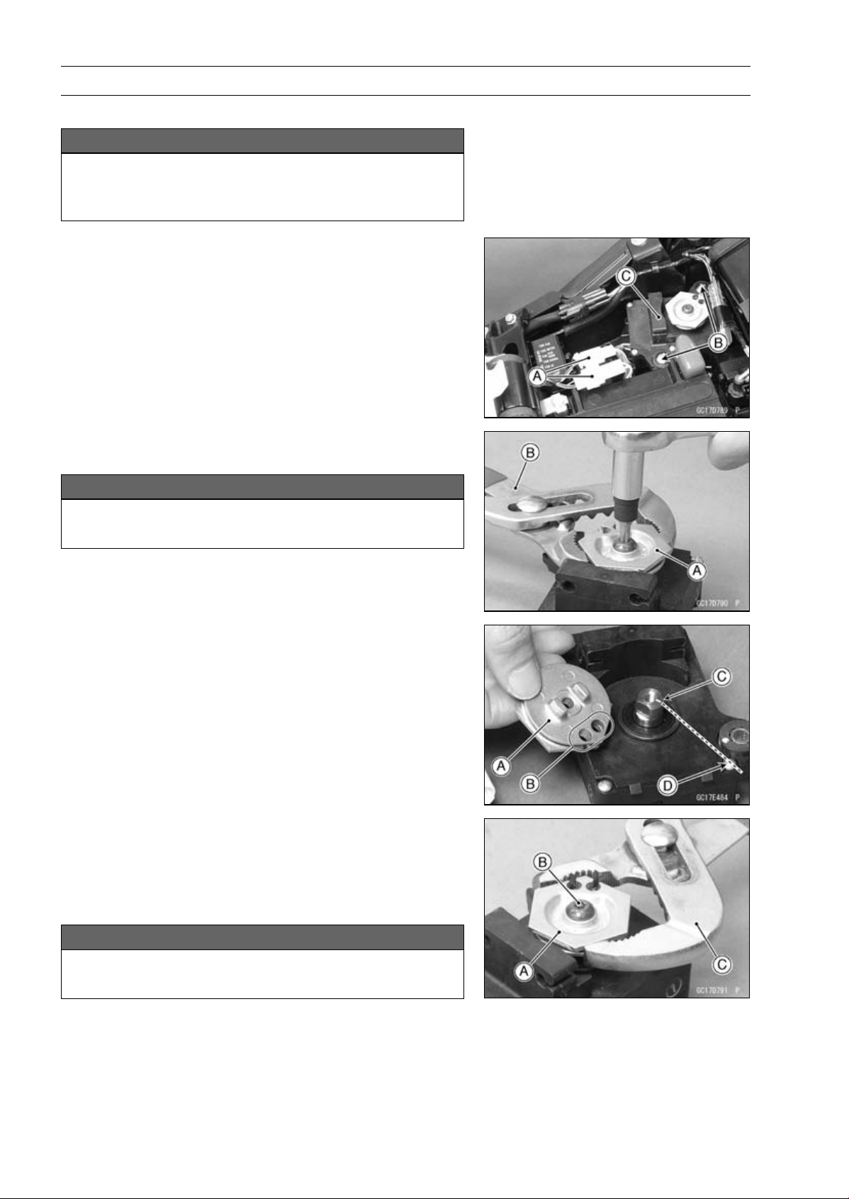
3-92 FUEL SYSTEM (DFI)
Exhaust Butterfly Valve Actuator (Service Code 63)
Exhaust Butterfly Valve Actuator Removal
NOTICE
Never drop the exhaust butterfly valve actuator es-
pecially on a hard surface. Such a shock to the ac-
tuator can damage it.
•
Remove:
Exhaust Butterfly Valve Cables (see Exhaust Butterfly
Valve Cable Removal in the Engine Top End chapter)
Connectors [A]
Screws [B]
Exhaust Butterfly Valve Actuator [C]
•
Remove the pulley bolt while holding the pulley [A] with
the suitable tool [B].
NOTICE
If the pulley bolt is removed without holding, the
actuator damage will occur.
•
Remove the pulley from the actuator.
Exhaust Butterfly Valve Actuator Installation
•
Install the pulley [A] on the actuator so that the hole side
[B] align with the groove [C] on the shaft.
○
Make sure that the groove on the shaft is pointing toward
the center of the screw [D].
○
If the shaft position is incorrect, refer to the following
NOTE and procedures to electrically adjust the shaft
position.
•
Install the pulley [A] on the actuator as shown.
•
Tighten the pulley bolt [B] while holding the pulley with the
suitable tool [C].
Torque - Exhaust Butterfly Valve Actuator Pulley Bolt: 5.0
N·m (0.51 kgf·m, 44 in·lb)
NOTICE
If the pulley bolt is tightened without holding, the
actuator damage will occur.
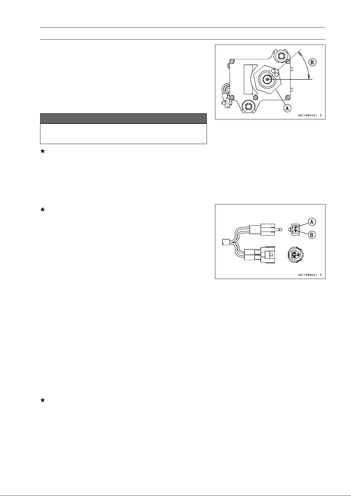
FUEL SYSTEM (DFI) 3-93
Exhaust Butterfly Valve Actuator (Service Code 63)
•
After tightening the pulley bolt, confirm whether pulley [A]
is an angle shown in the figure.
41.7° ±7° [B]
○
This position is original position of the pulley.
NOTE
○
Correct the position electrically after confirming the use
is discontinued and there is no damage when differing
from the angle of shown in the figure.
NOTICE
Do not correct the pulley position with the tool,
forcibly. The actuator damage will occur.
If the pulley angle is wrong, adjust the angle as follows.
○
Connect:
2 pins Connector
3 pins Connector
○
Turn the ignition switch ON.
○
Confirm the pulley turns clockwise or counterclockwise
then it stops at the original position.
If the pulley position has not been returned to the original
position, electrically adjust the shaft position as follows.
○
Remove:
2 pins Connector
3 pins Connector
○
Turn the pulley to the original position by turning it clock-
wise or counterclockwise by connecting the battery to the
2 pins connector terminals. To turn the pulley gradually,
intermittently connect the battery positive (+) terminal to
the 2 pin connector terminal while connecting the battery
negative (–) terminal to the connector.
Pink (–) lead terminal [A]
Gray (+) lead terminal [B]
Clockwise:
Pink (–) lead terminal to battery (–) terminal
Gray (+) lead terminal to battery (+) terminal
Counterclockwise:
Pink (–) lead terminal to battery (–) terminal
Gray (+) lead terminal to battery (+) terminal
○
Reconnect the 2 pins connector and 3 pins connector, and
turn the ignition switch ON.
○
Make sure that the pulley turns clockwise and then coun-
terclockwise.
○
The pulley should returns to the original position.
○
Turn the ignition switch OFF.
If the pulley does not return to the original position, check
the exhaust butterfly valve actuator resistance (see Ex-
haust Butterfly Valve Actuator Resistance Inspection).
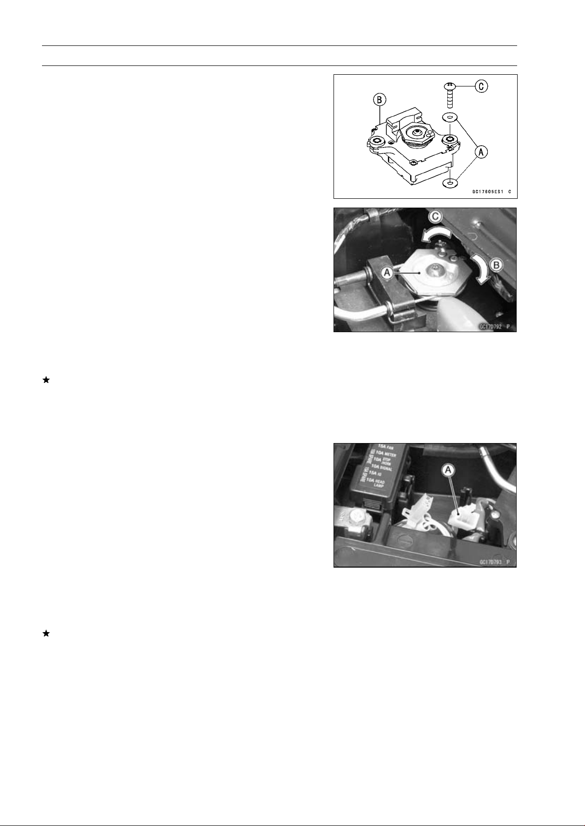
3-94 FUEL SYSTEM (DFI)
Exhaust Butterfly Valve Actuator (Service Code 63)
•
Be sure to install the washers [A] on the exhaust butterfly
valve actuator [B].
•
Tighten:
Torque - Exhaust Butterfly Valve Actuator Mounting
Screws[C]:1.2N·m(0.12kgf·m,11in·lb)
•
Install the close cable first and then open cable (see Ex-
haust Butterfly Valve Cable Installation in the Engine Top
End chapter).
Exhaust Butterfly Valve Actuator Inspection
NOTE
○
Be sure the battery is fully charged
•
Remove the front seat (see Front Seat Removal in the
Frame chapter).
•
Turn the ignition switch ON.
•
In the left side view of the motorcycle, check to see
the pulley [A] clockwise [B] and counterclockwise [C]
smoothly.
○
The pulley turns clockwise and then counterclockwise,
and clockwise again.
•
Turn the ignition switch OFF.
If the pulley does not operate, check the exhaust butterfly
valve cable installation (see Exhaust Butterfly Valve Ca-
ble Installation in the Engine Top End chapter) and the
exhaust butterfly valve actuator resistance (see Exhaust
Butterfly Valve Actuator Resistance Inspection).
Exhaust Butterfly Valve Actuator Resistance
Inspection
•
Turn the ignition switch OFF.
•
Disconnect the exhaust butterfly valve actuator lead con-
nector (2 pins connector) [A].
•
Set the hand tester to the × 1 Ω range and connect it to
the exhaust butterfly valve actuator connector.
Special Tool - Hand Tester: 57001-1394
•
Measure the exhaust butterfly valve actuator resistance.
Exhaust Butterfly Valve Actuator Resistance
Connections: P lead GY lead
Standard: Any Reading Resistance (reference
5
∼ 200 )
If the reading is 0 or infinity (∞) Ω, replace the exhaust
butterfly valve actuator.
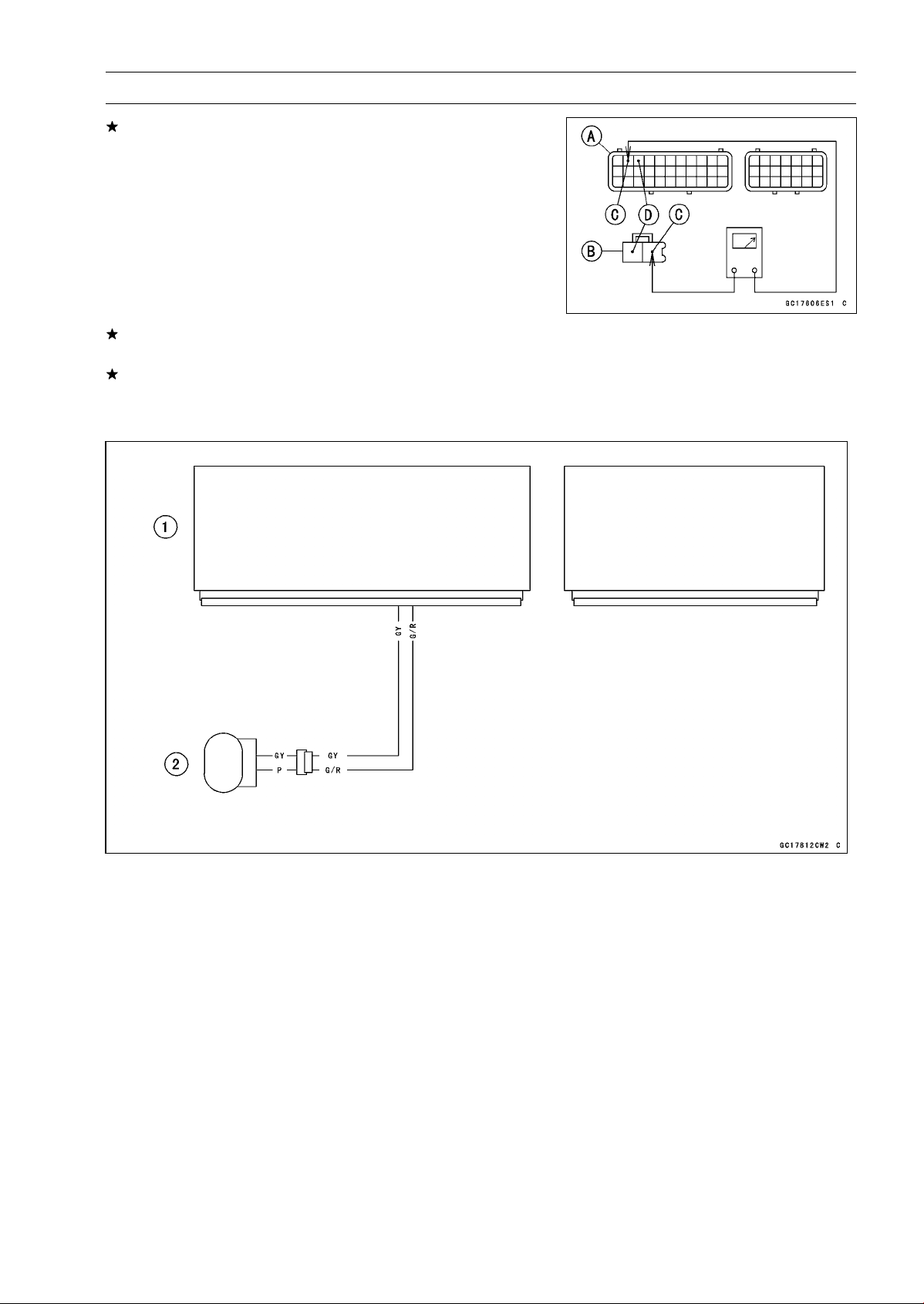
FUEL SYSTEM (DFI) 3-95
Exhaust Butterfly Valve Actuator (Service Code 63)
If the reading is in specification, remove the ECU and
check the wiring for continuity between main harness con-
nectors.
○
Disconnect the ECU and actuator connectors.
Wiring Inspection
ECU Connector [A]
Exhaust Butterfly Valve Actuator Connector [B]
GY lead (ECU terminal 2) [C]
G/Rlead(ECUterminal3)[D]
If the wiring is good, check the ECU for its ground and
power supply (see ECU Power Supply Inspection).
If the ground and power supply are good, replace the ECU
(see ECU Removal/Installation).
Exhaust Butterfly Valve Actuator Circuit
1. ECU
2. Exhaust Butterfly Valve Actuator
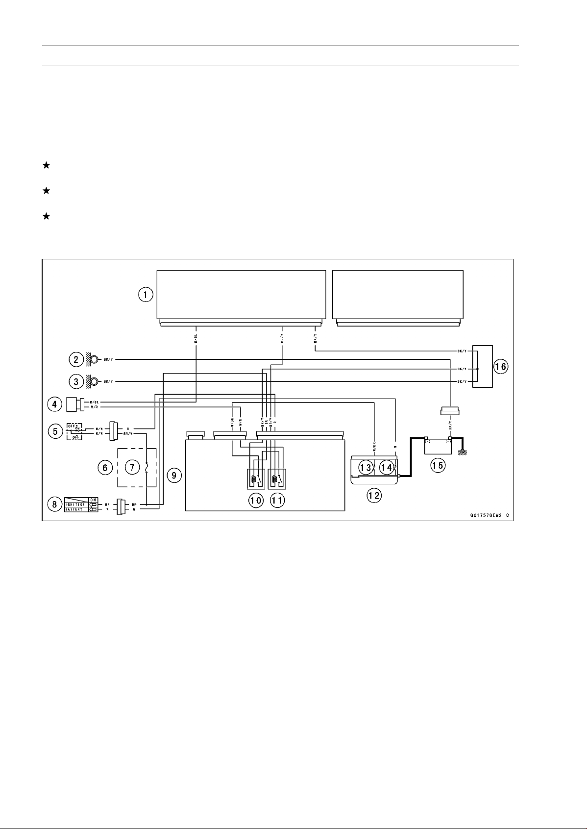
3-96 FUEL SYSTEM (DFI)
Air Switching Valve (Service Code 64)
Air Switching Valve Removal/Installation
•
Refer to the Air Switching Valve Removal/Installation in
the Engine Top End chapter.
Air Switching Valve Inspection
•
Refer to the Air Switching Valve Unit Test in the Electrical
System chapter.
If the air switching valve is normal, check the wiring for
continuity (see wiring diagram in this section).
If the wiring is good, check the ECU for its ground and
power supply (see ECU Power Supply Inspection).
If the ground and power supply are good, replace the ECU
(see ECU Removal/Installation).
Air Switching Valve Circuit
1. ECU
2. Frame Ground
3. Meter Ground
4. Air Switching Valve
5. Engine Stop Switch
6. Fuse Box
7. Ignition Fuse 15 A
8. Ignition Switch
9. Relay Box
10. ECU Main Relay
11. Fuel Pump Relay
12. Starter Relay
13. FI Fuse 15 A
14. Main Fuse 30 A
15. Battery 12 V 8 Ah
16. Water-proof Joint C

FUEL SYSTEM (DFI) 3-97
Oxygen Sensor Heater (Service Code 67, Equipped Models)
Oxygen Sensor Heater Removal/Installation
The oxygen sensor heater is built in the oxygen sensor.
So, the heater itself can not be removed. Remove the oxy-
gen sensor (see Oxygen Sensor Removal (Equipped Mod-
els) in the Electrical System chapter).
Oxygen Sensor Heater Resistance Inspection
•
Turn the ignition switch OFF.
•
Open the clamp [A], and pull out the oxygen sensor lead
connector [B].
•
Disconnect the oxygen sensor lead connector.
•
Connect a digital meter [A] to the oxygen sensor lead con-
nector [B].
•
Measure the oxygen sensor heater resistance.
Oxygen Sensor Heaters Resistance
Connections: BK lead [C] BK lead [D]
Standard: 11.7
∼ 14.5 at 20° C (68°F)
If the reading is out of the standard, replace the sensor.
If the reading is within the standard, check the power
source voltage (see Oxygen Sensor Heat
er Power
Source Voltage Inspection).
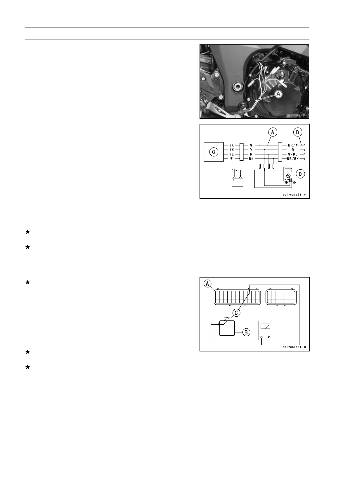
3-98 FUEL SYSTEM (DFI)
Oxygen Sensor Heater (Service Code 67, Equipped Models)
Oxygen Sensor Heater Power Source Voltage
Inspection
NOTE
○
Be sure the battery is fully charged.
•
Turn the ignition switch OFF.
•
Disconnect the oxygen sensor lead connector and con-
nect the harness adapter [A] between these connectors.
[B] Main Harness
[C] Oxygen Sensor
Special Tool - Measuring Adapter: 57001-1700
•
Connect a digital meter [D] to the harness adapter lead.
Oxygen Sensor Power Source Voltage
Connections to Adapter:
Digital Meter (+) Y (sensor BK) lead
Digital Meter (–) Battery (–) terminal
•
Measure the power source voltage with the engine
stopped and with the connector joined.
•
Turn the ignition switch ON.
Power Source Voltage
Standard: Battery Voltage
•
Turn the ignition switch OFF.
If the reading is in specification, but the problem still ex-
ists, replace the ECU (see ECU Removal/Installation).
If the reading is out of the standard, check the following.
FI Fuse 15 A (see Fuse Inspection in the Electrical Sys-
tem chapter)
Power Source Wiring (see wiring diagram in this section)
If the fuse and wiring are good, remove the ECU and
check the wiring for continuity between main harness con-
nectors.
○
Disconnect the ECU and sensor connectors.
Wiring Inspection
ECU Connector [A]
Oxygen Sensor Connector [B]
R lead (ECU terminal 9) [C]
If the wiring is good, check the ECU for its ground and
power supply (see ECU Power Supply Inspection).
If the ground and power supply are good, replace the ECU
(see ECU Removal/Installation).
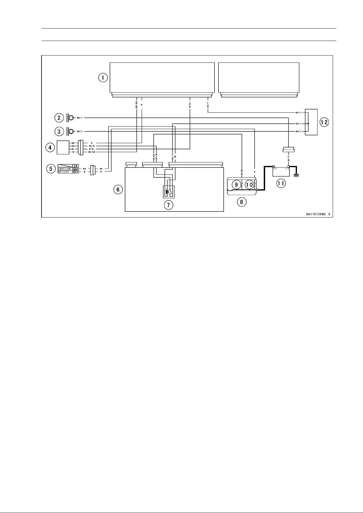
FUEL SYSTEM (DFI) 3-99
Oxygen Sensor Heater (Service Code 67, Equipped Models)
Oxygen Sensor Circuit
1. ECU
2. Frame Ground
3. Meter Ground
4. Oxygen Sensor
5. Ignition Switch
6. Relay Box
7. ECU Main Relay
8. Starter Relay
9. FI Fuse 15 A
10. Main Fuse 30 A
11. Battery 12 V 8 Ah
12. Water-proof Joint C
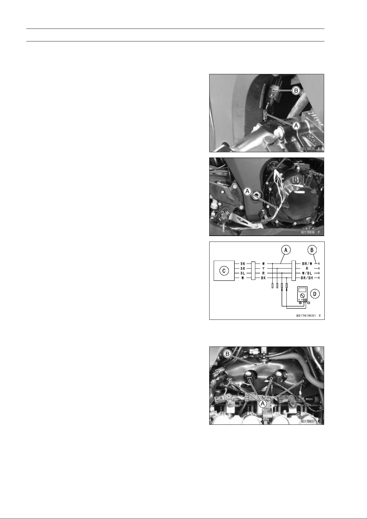
3-100 FUEL SYSTEM (DFI)
Oxygen Sensor - Incorrect Output Voltage (Service Code 94, Equipped Models)
Oxygen Sensor Removal/Installation
•
Refer to the Oxygen Sensor Removal/Installation in the
Electrical System chapter.
Oxygen Sensor Inspection
•
Warm up the engine thoroughly until the radiator fan
starts.
•
Turn the ignition switch OFF.
•
Open the clamp [A], and pull out the oxygen sensor lead
connector [B].
•
Disconnect the oxygen sensor lead connector (4 pins
connector) and connect the harness adapter [A] between
these connectors.
[B] Main Harness
[C] Oxygen Sensor
Special Tool - Measuring Adapter: 57001-1700
•
Connect a digital meter [D] to the harness adapter leads.
Oxygen Sensor Output Voltage
Connections to Adapter:
Digital Meter (+) R (sensor BL) lead
Digital Meter () BK (sensor W) lead
•
Remove:
Air Cleaner Housing (see Air Cleaner Housing Removal)
•
Disconnect the stick coil connectors [A].
•
Turn over the rubber plate [B].

FUEL SYSTEM (DFI) 3-101
Oxygen Sensor - Incorrect Output Voltage (Service Code 94, Equipped Models)
•
Separate the air switching valve hoses [A] from the air
suction valve covers.
○
Do not disconnect the air switching valve connector [B].
•
Install the suitable plugs [A] on the fitting of the air suction
valve covers, and shut off the secondary air.
•
Connect the stick coil connectors.
•
Install the air cleaner housing temporarily (see Air Cleaner
Housing Installation).
•
Remove the fuel hose (see Fuel Tank Removal).
•
Connect the following parts temporary.
Fuel Pump Lead Connector [A]
Fuel Hose [B]
Special Tool - Fuel Hose: 57001-1607
•
Start the engine, and let it idle.
•
Measure the output voltage with the connector joined.
Output Voltage (with Plugs)
Standard: DC 0.7 V or more
•
Next, remove the air cleaner housing to take out the plugs
from the fittings [A] of the air suction valve covers.
•
Install the air cleaner housing.
•
Start the engine, and let it idle.
•
Measure the output voltage with the connector joined.
Output Voltage (without Plugs)
Standard: DC 0.2 V or less
•
Turn the ignition switch OFF.
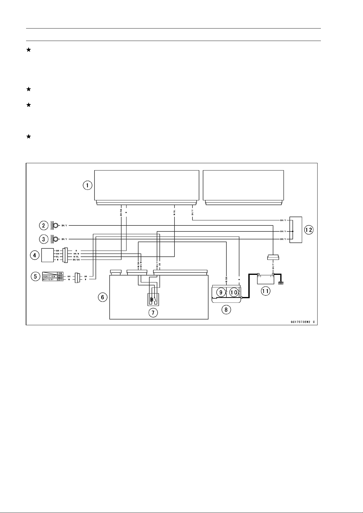
3-102 FUEL SYSTEM (DFI)
Oxygen Sensor - Incorrect Output Voltage (Service Code 94, Equipped Models)
If the reading is out of the standard (with plugs: DC 0.7
V or more, without plugs: DC 0.2 V or less), check the
following.
Fuel Pressure (see Fuel Pressure Inspection)
Fuel Injector (see Fuel Injectors section)
If the fuel pressure and fuel injectors are good, replace
the sensor.
If the reading is within the standard (with plugs: DC 0.7 V
or more, without plugs: DC 0.2 V or less), check the ECU
for its ground and power supply (see ECU Power Supply
Inspection).
If the ground and power supply are good, replace the ECU
(see ECU Removal/Installation).
Oxygen Sensor Circuit
1. ECU
2. Frame Ground
3. Meter Ground
4. Oxygen Sensor
5. Ignition Switch
6. Relay Box
7. ECU Main Relay
8. Starter Relay
9. FI Fuse 15 A
10. Main Fuse 30 A
11. Battery 12 V 8 Ah
12. Water-proof Joint C
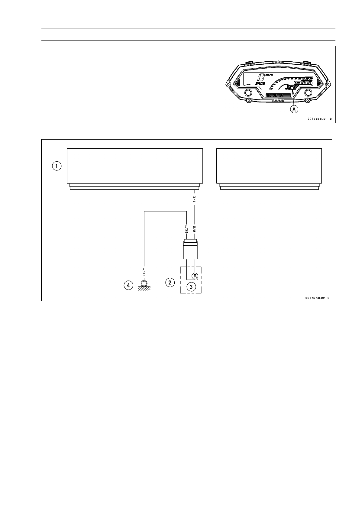
FUEL SYSTEM (DFI) 3-103
Warning Indicator Light (LED)
Light (LED) Inspection
○
The warning indicator light (LED) [A] is used for the FI
indicator, immobilizer indicator (immobilizer models) and
oil pressure warning indicator.
○
In this model, the warning indicator light (LED) (FI/immo-
bilizer) blink by the data sent from the ECU.
•
Refer to the Meter Unit Inspection in the Electrical System
chapter for the warning indicator light (LED) (FI/immobi-
lizer) inspection.
Warning Indicator Light (LED) (FI/Immobilizer) Circuit
1. ECU
2. Meter Unit
3. Warning Indicator Light (LED)
4. Meter Ground
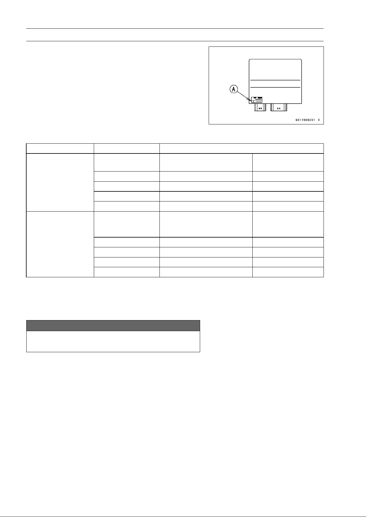
3-104 FUEL SYSTEM (DFI)
ECU
ECU Identification
○
Most countries have their own regulations, so each ECU
has different characteristic. So, do not confuse ECU with
each other and use only the ECU for your model. Other-
wise, the motorcycle cannot clear the regulation.
ECU Identification
Model Part Number [A] Specification
21175-0272
WVTA (Full H)
GB WVTA (Full H)
with immobilizer
21175-0274 US, CAL and CA without immobilizer
21175-0277
WVTA (78.2)
with immobilizer
21175-0319 SEA-B1 and MY with immobiliz
er
ZR1000DA
ZR1000EA
21175-0321 BR with immobilizer
21175-0343
WVTA (Full H)
GB WVTA (Full H)
PH
with immobilizer
21175-0274 US, CAL and CA without immobilizer
21175-0344 WVTA (78.2) with immobilizer
21175-0345 SEA-B1/B2 and TH with immobilizer
ZR1000DB ∼
ZR1000EB ∼
21175-0346 BR with immobilizer
Full: Full Power
H: Honeycomb Type Catalyst
78.2: Maximum Horsepower 78.2 kW (106.3 PS)
ECU Removal
NOTICE
Never drop the ECU especially on a hard surface.
Such a shock to the ECU can damage it.
NOTE
○
Refer to the Immobilizer System Parts Replacement in
the Electrical System chapter for the immobilizer mod-
els (see Immobilizer System Parts Replacement in the
Electrical System chapter).
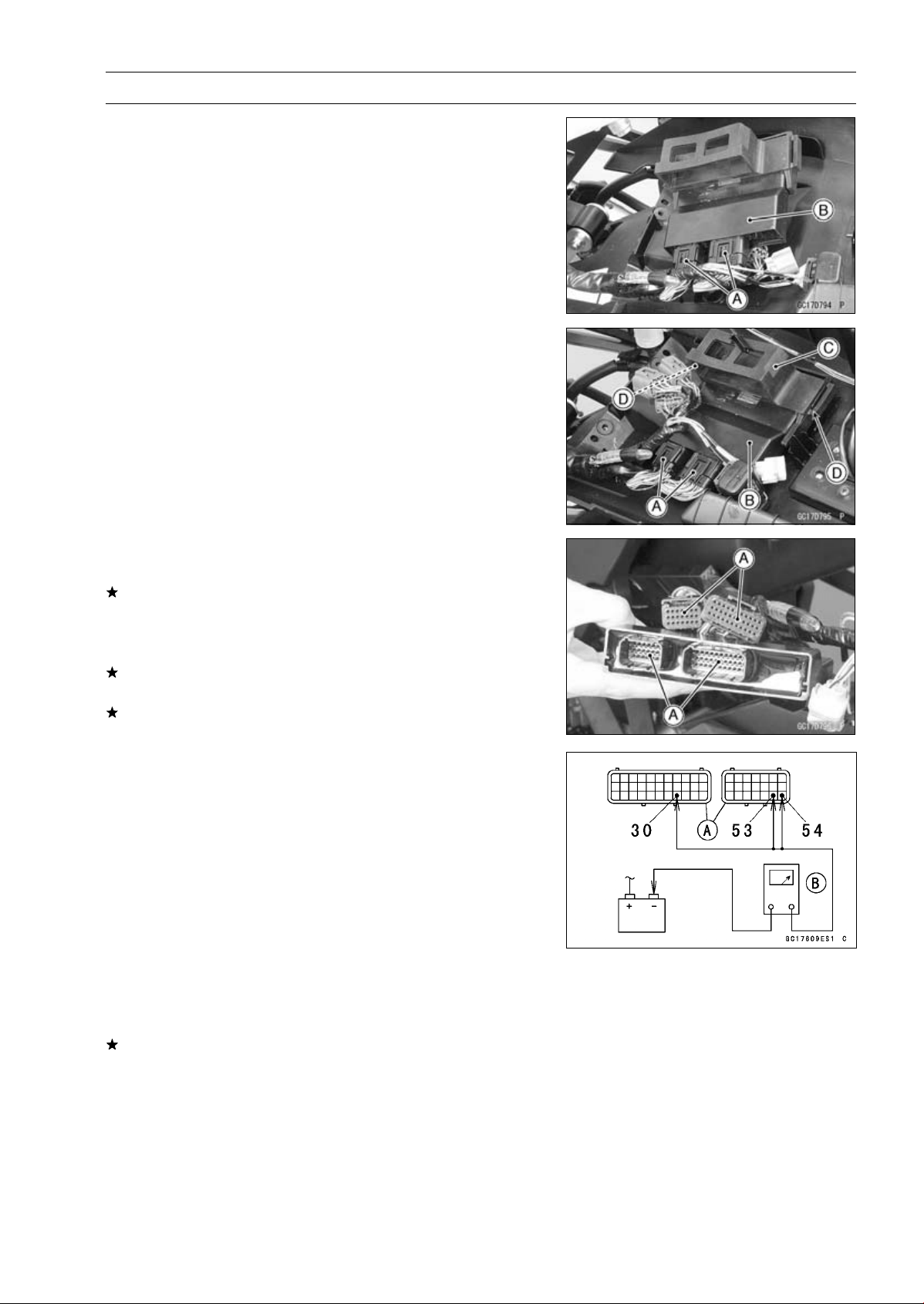
FUEL SYSTEM (DFI) 3-105
ECU
•
Remove:
Relay Box (see Relay Box Removal in the Electrical Sys-
tem chapter)
ECU Connectors [A]
ECU [B]
ECU Installation
•
Connect the ECU connectors [A].
•
Install the ECU [B] into the rubber protector [C].
•
Insert the slits of the rubber protector to the projections
[D]ofthebracket.
ECU Power Supply Inspection
•
Visually inspect the ECU connectors.
If the connector is clogged with mud or dust, blow it off
with compressed air.
•
Remove the ECU (see ECU Removal).
•
Visually inspect the terminals [A] of the ECU connectors.
If the terminals of the main harness connectors are dam-
aged, replace the main harness.
If the terminals of the ECU connectors are damaged, re-
place the ECU.
•
Turn the ignition switch OFF.
•
Disconnect the ECU connectors [A].
•
Set the hand tester [B] to the × 1 Ω range and check the
following wiring for continuity.
Special Tool - Hand Tester: 57001-1394
ECU Grounding Inspection
Connections:
(I) BK/Y leads (ECU
terminal 30, 53 or 54)
Battery (–) Terminal
(II) Engine Ground
Battery (–) Terminal
Criteria:
Both: 0
If no continuity, check the connectors, the engine ground
lead, or main harness, and repair or replace them if nec-
essary.

3-106 FUEL SYSTEM (DFI)
ECU
If the wiring is good, check the power source voltage of
the ECU.
NOTE
○
Be sure the battery is fully charged.
•
Connect the ECU and relay box connectors.
•
Connect a digital meter [A] to the connectors [B] with the
needle adapter set.
Special Tool - Needle Adapter Set: 57001-1457
ECU Power Supply Inspection
Connections:
(I) Digital Meter (+) Terminal 6 (BR/W)
Digital Meter (–) Battery (–) terminal
(II) Digital Meter (+) Terminal 8 (W/BK)
Digital Meter (–) Battery (–) terminal
Ignition Switch OFF:
Terminal 6 (BR/W): 0 V
Terminal 8 (W/BK): Battery Voltage
Ignition Switch ON:
Both: Battery Voltage
If the reading is out of the specification, check the follow-
ing.
Main Fuse 30 A (see Fuse Inspection in the Electrical
System chapter)
FI Fuse 15 A (see Fuse Inspection Electrical System
chapter)
ECU Main Relay (see Relay Circuit Inspection in the
Electrical System chapter)
Power Source Wiring (see wiring diagram in this sec-
tion )
If the fuse, wiring and relay are good, replace the ECU
(see ECU Removal/Installation).
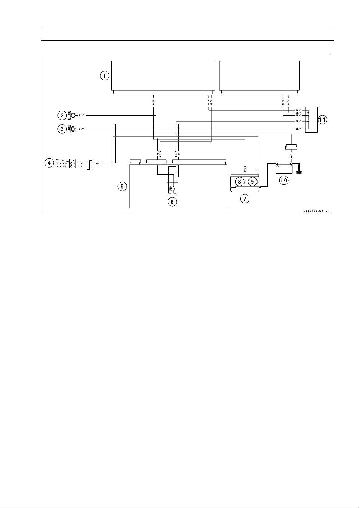
FUEL SYSTEM (DFI) 3-107
ECU
ECU Power Source Circuit
1. ECU
2. Frame Ground
3. Meter Ground
4. Ignition Switch
5. Relay Box
6. ECU Main Relay
7. Starter Relay
8. FI Fuse 15 A
9. Main Fuse 30 A
10. Battery 12 V 8 Ah
11. Water-proof Joint C
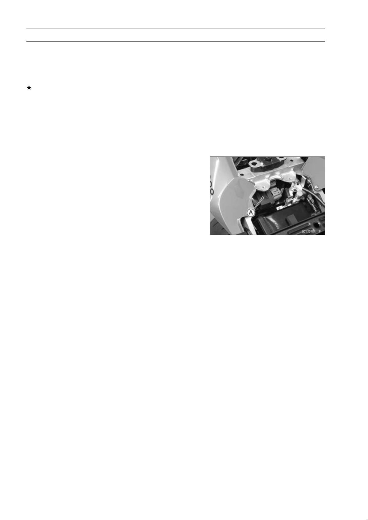
3-108 FUEL SYSTEM (DFI)
DFI Power Source
ECU Fuse Removal
•
Refer to the 15 A FI Fuse Removal in the Electrical Sys-
tem chapter.
ECU Fuse Installation
If a fuse fails during operation, inspect the DFI system to
determine the cause, and then replace it with a new fuse
of proper amperage.
•
Refer to the Fuse Installation in the Electrical System
chapter.
ECU Fuse Inspection
•
Refer to the Fuse Inspection in the Electrical System
chapter.
ECU Main Relay Removal/Installation
○
The ECU main relay is built in the relay box [A].
•
Refer to the Relay Box Removal in the Electrical System
chapter.
ECU Main Relay Inspection
•
Refer to the Relay Circuit Inspection in the Electrical Sys-
tem chapter.
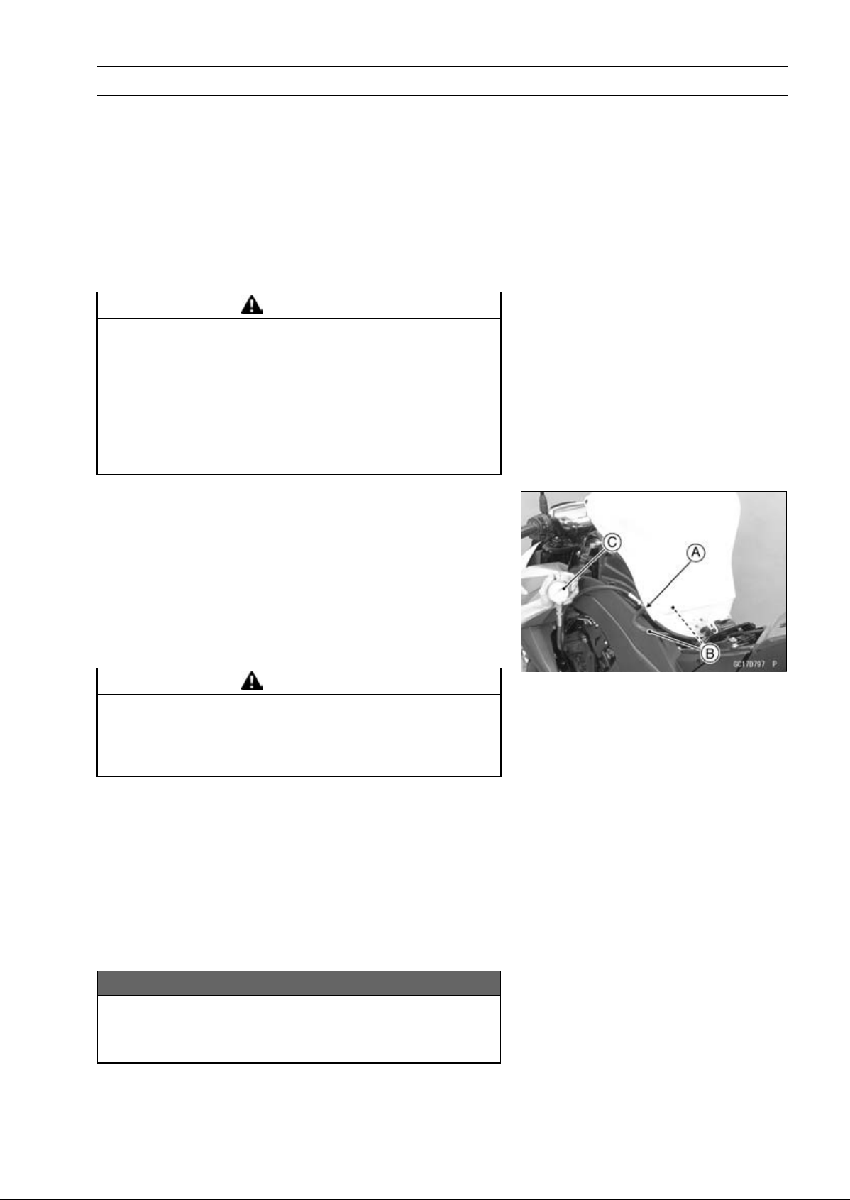
FUEL SYSTEM (DFI) 3-109
Fuel Line
Fuel Pressure Inspection
NOTE
○
Be sure the battery is fully charged.
•
Remove:
Fuel Tank (see Fuel Tank Removal)
Fuel Hose (see Fuel Tank Removal)
○
Be sure to place a piece of cloth around the fuel outlet
pipe of the fuel pump and the delivery pipe of the throttle
body assy.
WARNING
Fuel is flammable and explosive under certain con-
ditions and can cause severe burns. Be prepared
for fuel spillage; any spilled fuel must be completely
wiped up immediately. When the fuel hose is dis-
connected, fuel spills out from the hose and the
pipe because of residual pressure. Cover the hose
connection with a piece of clean cloth to prevent
fuel spillage.
•
Install the fuel pressure gauge adapter [A] and fuel hoses
(Special Tool: 57001-1607) [B] between the fuel outlet
pipe and delivery pipe.
•
Secure the fuel hoses with the clamps.
•
Connect the pressure gauge [C] to the fuel pressure
gauge adapter.
Special Tools - Oil Pressure Gauge, 5 kgf/cm²: 57001-125
Fuel Pressure Gauge Adapter: 57001-1593
Fuel Hose: 57001-1607
WARNING
Fuel is extremely flammable and can be explosive
under certain conditions resulting in serious injury
or death. Do not try to start the engine with the fuel
hoses disconnected.
•
Connect the fuel pump lead connector.
•
Turn the engine stop switch run position.
•
Turn the ignition switch ON.
○
The fuel pump should operate for 3 seconds, and then
should stop.
NOTE
○
After turning on the engine stop switch and ignition
switch, inspect the fuel leakage from the connected
portion of the special tools.
NOTICE
Do not drive the fuel pump 3 seconds or more with-
out the fuel in the fuel tank. If the fuel pump is driven
without the fuel, it may be damaged.
3-110 FUEL SYSTEM (DFI)
Fuel Line
•
Start the engine, and let it idle.
•
Measure the fuel pressure with the engine idling.
Fuel Pressure (with Engine Idling)
Standard: 294kPa(3.0kgf/cm²,43psi)
NOTE
○
The gauge needle will fluctuate. Read the pressure at
the average of the maximum and minimum indications.
•
Turn the ignition switch OFF.
If the fuel pressure is much higher than specified, replace
the fuel pump because the fuel pressure regulator in the
fuel pump have been clogged or stuck.
If the fuel pressure is much lower than specified, check
the following.
Fuel Line Leakage (see Fuel Injector Fuel Line Inspec-
tion)
Amount of Fuel Flow (see Fuel Flow Rate Inspection)
•
After above checks, measure the fuel pressure again.
•
Remove the fuel pressure gauge, hoses and adapter.
•
Install:
Fuel Hose (see Fuel Tank Installation)
Fuel Tank (see Fuel Tank Installation)
•
Confirm that the drain hose and clamp are installed se-
curely and run the hose correctly (see Cable, Wire, and
Hose Routing section in the Appendix chapter).
•
Start the engine and check for fuel leakage.
Fuel Flow Rate Inspection
WARNING
Gasoline is extremely flammable and can be ex-
plosive under certain conditions, creating the
potential for serious burns. Make sure the area is
well-ventilated and free from any source of flame
or sparks; this includes any appliance with a pilot
light. Do not smoke. Turn the ignition switch OFF.
Be prepared for fuel spillage; any spilled fuel must
be completely wiped up immediately.
NOTE
○
Be sure the battery is fully charged.
•
Turn the ignition switch OFF.
•
Wait until the engine cools down.
•
Prepare a fuel hose (Special Tool: 57001-1607) and a
measuring cylinder.
Special Tool - Fuel Hose: 57001-1607
•
Support the fuel tank with the suitable bar (see Fuel Tank
Removal).
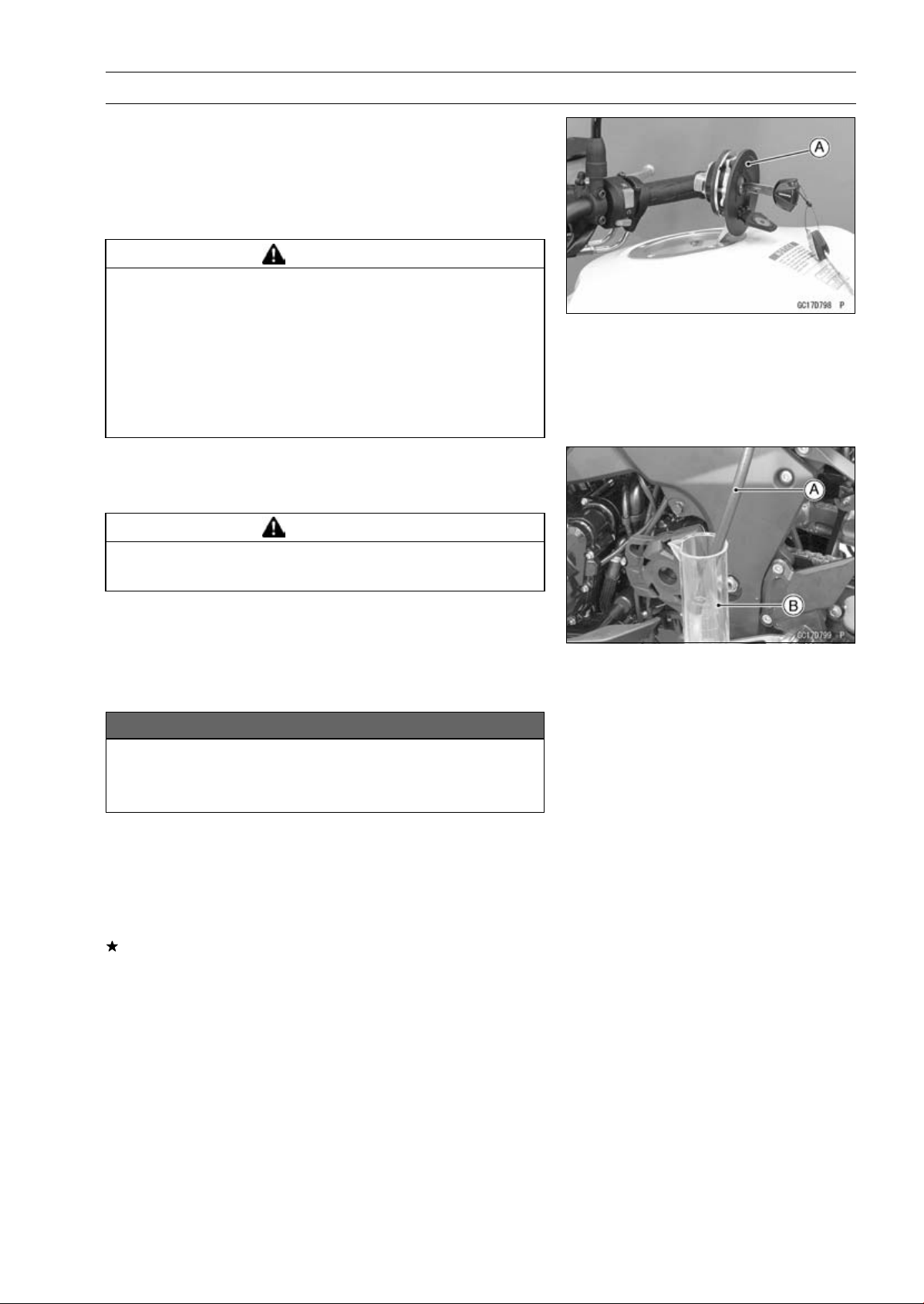
FUEL SYSTEM (DFI) 3-111
Fuel Line
•
Open the fuel tank cap [A] to lower the pressure in the
tank.
•
Remove the fuel hose from the fuel pump (see Fuel Tank
Removal).
○
Be sure to place a piece of cloth around the fuel outlet
pipe of the fuel pump.
WARNING
Fuel is flammable and explosive under certain con-
ditions and can cause severe burns. Be prepared
for fuel spillage; any spilled fuel must be completely
wiped up immediately. When the fuel hose is dis-
connected, fuel spills out from the hose and the
pipe because of residual pressure. Cover the hose
connection with a piece of clean cloth to prevent
fuel spillage.
•
Connect the prepared fuel hose [A] to the fuel outlet pipe.
•
Secure the fuel hose with a clamp.
•
Insert the fuel hose into the measuring cylinder [B].
WARNING
Wipe off spilled out fuel immediately.
Be sure to hold the measuring cylinder vertical.
•
Close the fuel tank cap.
•
Turn the engine stop switch to run position.
•
Turn the ignition switch ON.
○
The fuel pump should operate for 3 seconds, and then
should stop.
NOTICE
Do not drive the fuel pump 3 seconds or more with-
out the fuel in the fuel tank. If the fuel pump is driven
without the fuel, it may be damaged.
•
Measure the discharge for 3 seconds.
○
Repeat this operation several times.
Amount of Fuel Flow
Standard: 50mL(1.7USoz.)ormorefor3seconds
•
Turn the ignition switch OFF.
If the fuel flow is much less than the specified, replace the
fuel pump (see Fuel Pump Removal/Installation).
•
Install the fuel tank (see Fuel Tank Installation).
•
Confirm that the drain hose and clamp are installed se-
curely and run the hose correctly (see Cable, Wire, and
Hose Routing section in the Appendix chapter).
•
Start the engine and check for fuel leakage.
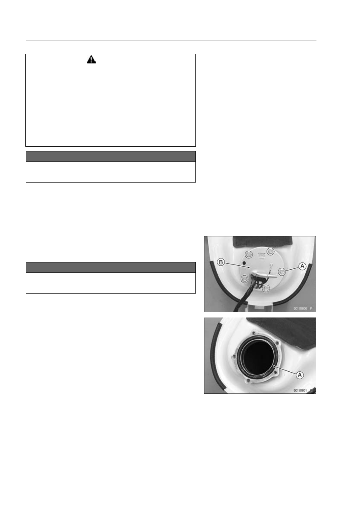
3-112 FUEL SYSTEM (DFI)
Fuel Pump
Fuel Pump Removal
WARNING
Gasoline is extremely flammable and can be ex-
plosive under certain conditions, creating the
potential for serious burns. Make sure the area is
well-ventilated and free from any source of flame
or sparks; this includes any appliance with a pilot
light. Do not smoke. Turn the ignition switch OFF.
Disconnect the battery (–) terminal. To avoid fuel
spills, draw it from the tank when the engine is
cold. Be prepared for fuel spillage; any spilled fuel
must be completely wiped up immediately.
NOTICE
Never drop the fuel pump especially on a hard sur-
face. Such a shock to the pump can damage it.
•
Draw the fuel out from the fuel tank with a commercially
available electric pump.
•
Remove the fuel tank (see Fuel Tank Removal).
○
Be careful of fuel spillage from the fuel tank since fuel still
remains in the fuel tank and fuel pump. Plug the fuel pipe
of the fuel tank.
•
Turn the fuel tank upside down.
•
Remove the fuel pump bolts [A], and take out the fuel
pump [B].
NOTICE
Do not pull the leads of the fuel pump. If they are
pulled, the lead terminals may be damaged.
•
Discard the fuel pump gasket [A].
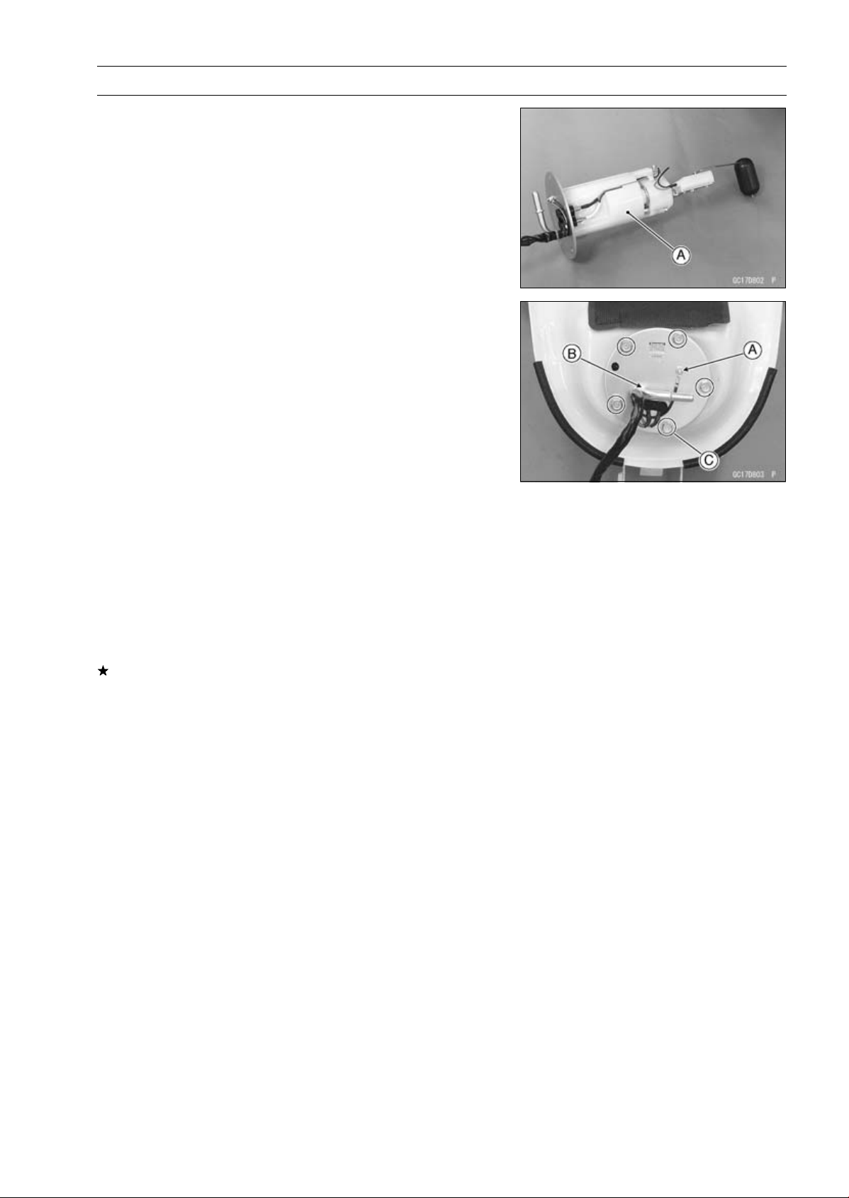
FUEL SYSTEM (DFI) 3-113
Fuel Pump
Fuel Pump Installation
•
Remove dirt or dust from the fuel pump [A] by lightly ap-
plying compressed air.
•
Replace the fuel pump gasket with a new one.
•
Check that the fuel pump terminal [A] and band [B] are in
place.
•
Apply a non-permanent locking agent to the threads of
the fuel pump bolts.
•
Tighten the fuel pump bolts [C] to a snug fit.
•
Tighten the fuel pump bolts alternating diagonally.
Torque - Fuel Pump Bolts: 9.8 N·m (1.0 kgf·m, 87 in·lb)
•
Tighten the pump bolts again to check the tightness.
Fuel Pump Operation Inspection
NOTE
○
Be sure the battery is fully charged.
•
Turn the engine stop switch to run position.
•
Turn the ignition switch ON and make sure that the fuel
pump operates (make light sounds) for 3 seconds, and
then stops.
•
Turn the ignition switch OFF.
If the pump does not operate as described above, check
the operating voltage (see Fuel Pump Operating Voltage
Inspection).
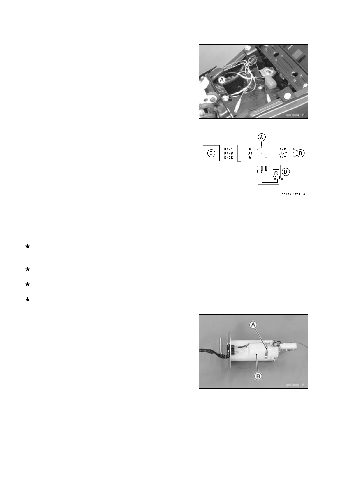
3-114 FUEL SYSTEM (DFI)
Fuel Pump
Fuel Pump Operating Voltage Inspection
NOTE
○
Be sure the battery is fully charged.
•
Turn the ignition switch OFF.
•
Remove the front seat (see Front Seat Removal in the
Frame chapter).
•
Disconnect the fuel pump lead connector and connect the
harness adapter [A] between these connectors as shown.
Main Harness [B]
Fuel Pump [C]
Special Tool - Measuring Adapter: 57001-1700
•
Connect a digital meter [D] to the harness adapter leads.
Fuel Pump Operating Voltage
Connections to Adapter:
Digital Meter (+) R (pump BK/Y) lead
Digital Meter (–) BK (pump BK/W) lead
•
Measure the operating voltage with engine stopped and
with the connector joined.
•
Turn the engine stop switch run position.
•
Turn the ignition switch ON.
Operating Voltage
Standard: Battery Voltage for 3 seconds, and then 0 V
•
Turn the ignition switch OFF.
If the reading is not the standard, check the ECU main
relay and fuel pump relay (see Relay Circuit Inspection in
the Electrical System chapter).
If the main relay and pump relay are normal, check the
wiring for continuity (see Fuel Pump Circuit).
If the wiring is good, check the ECU for its ground and
power supply (see ECU Power Supply Inspection).
If the ground and power supply are good, replace the ECU
(see ECU Removal/Installation).
Pressure Regulator Removal
○
The pressure regulator [A] is built into the fuel pump [B]
and can not be removed.
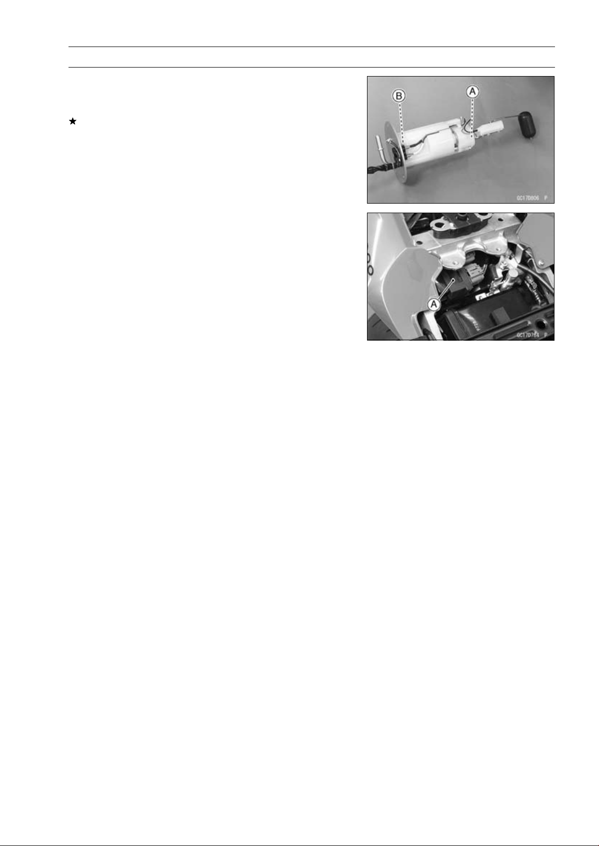
FUEL SYSTEM (DFI) 3-115
Fuel Pump
Pump Screen, Fuel Filter Cleaning
○
The pump screen [A] and fuel filter [B] are built into the
pump and can not be cleaned or checked.
If the pump screen or fuel filter is suspected of clogging
or being damaged, replace it with the fuel pump as a set.
Fuel Pump Relay Removal/Installation
○
The fuel pump relay is built in the relay box [A].
•
Refer to the Relay Box Removal in the Electrical System
chapter.
Fuel Pump Relay Inspection
•
Refer to the Relay Circuit Inspection in the Electrical Sys-
tem chapter.
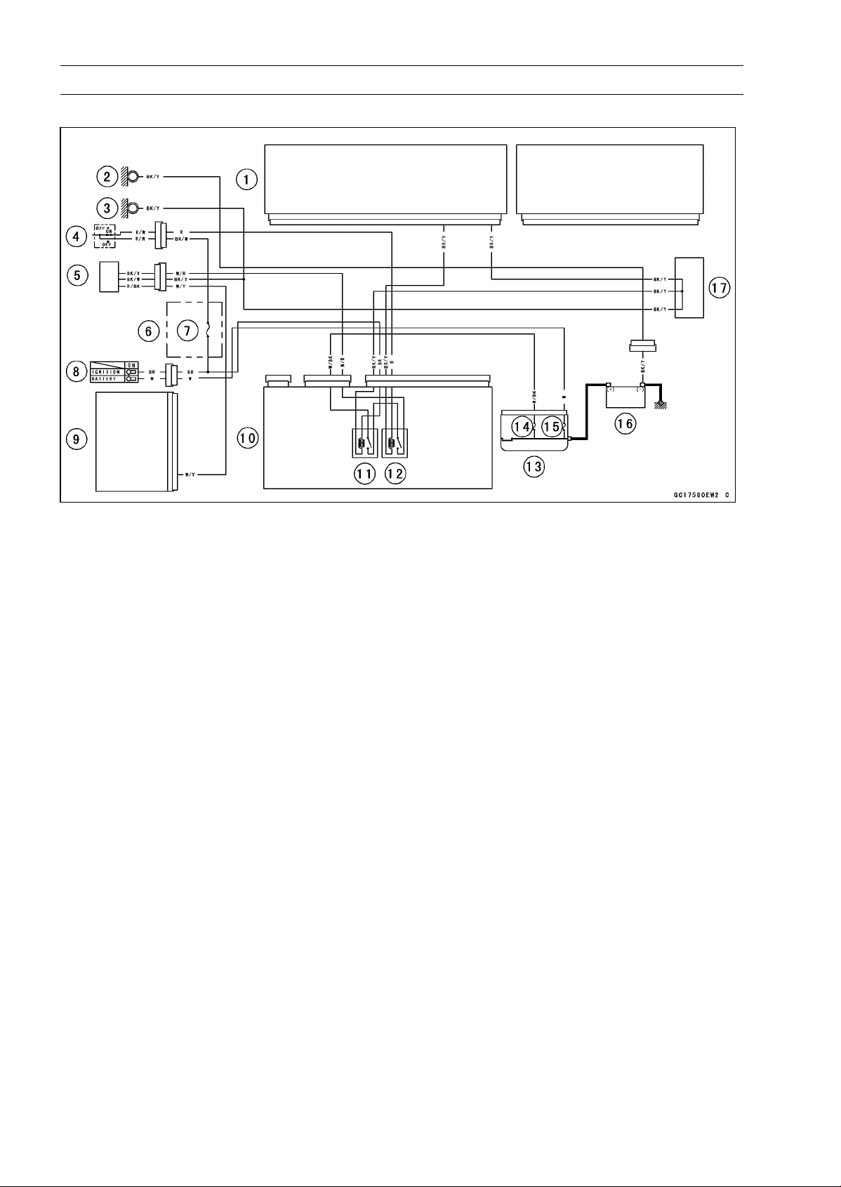
3-116 FUEL SYSTEM (DFI)
Fuel Pump
Fuel Pump Circuit
1. ECU
2. Frame Ground
3. Meter Ground
4. Engine Stop Switch
5. Fuel Pump/Fuel Level Sensor
6. Fuse Box
7. Ignition Fuse 15 A
8. Ignition Switch
9. Meter Unit
10. Relay Box
11. ECU Main Relay
12. Fuel Pump Relay
13. Starter Relay
14. FI Fuse 15 A
15. Main Fuse 30 A
16. Battery 12 V 8 Ah
17. Water-proof Joint C
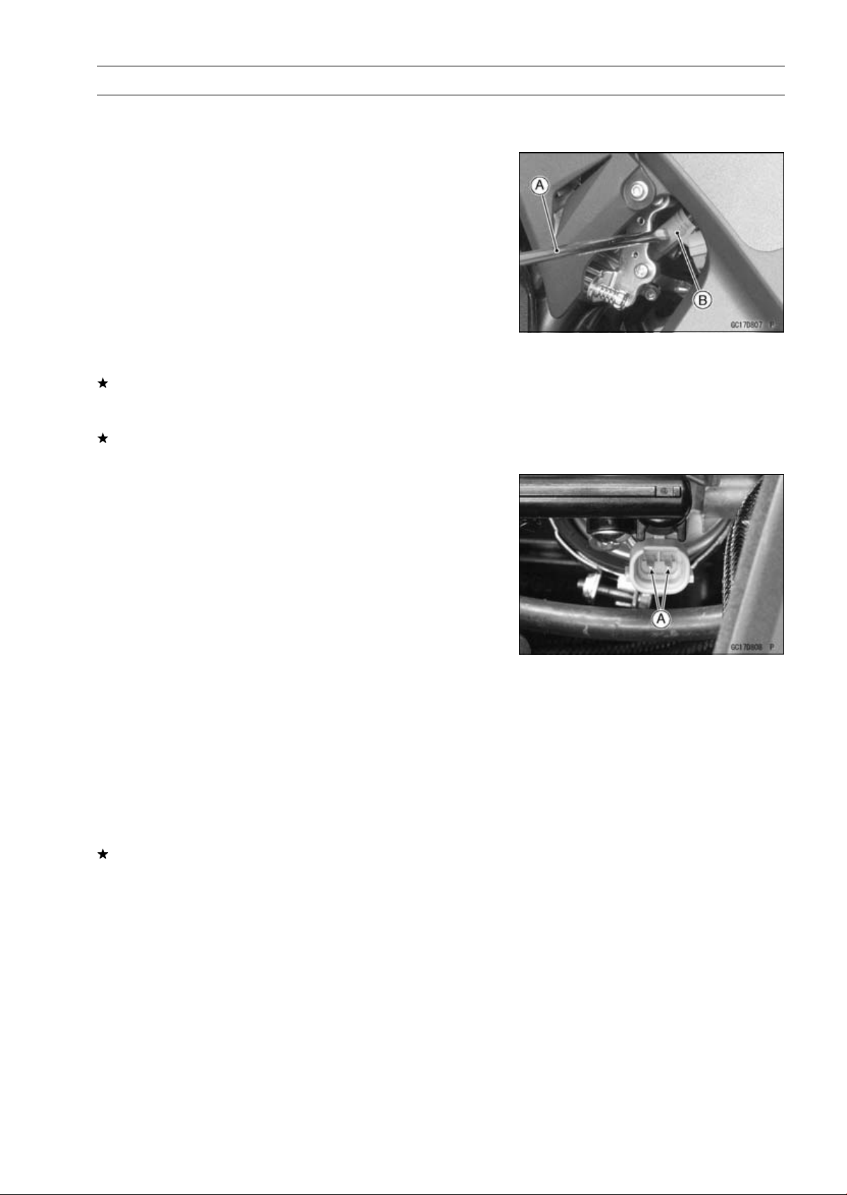
FUEL SYSTEM (DFI) 3-117
Fuel Injectors
Fuel Injector Removal/Installation
•
Refer to the Throttle Body Assy Disassembly/Assembly.
Fuel Injector Audible Inspection
NOTE
○
Be sure the battery is fully charged.
•
Start the engine, and let it idle.
•
Apply the tip of a screwdriver [A] to the fuel injector [B].
Put the grip end onto your ear, and listen whether the fuel
injector is clicking or not.
○
A sound scope can also be used.
○
The click interval becomes shorter as the engine speed
rises.
•
Do the same for the other fuel injectors.
If all the fuel injectors click at a regular intervals, the fuel
injectors are normal.
•
Turn the ignition switch OFF.
If any fuel injector does not click, check the fuel injector
resistance (see Fuel Injector Resistance Inspection).
Fuel Injector Resistance Inspection
•
Remove the throttle body assy with the connectors in-
stalled (see Throttle Body Assy Removal).
•
Disconnect the injector connector.
•
Connect a digital meter to the terminals [A] of the injector.
•
Measure the fuel injector resistance.
Fuel Injector Resistance
Connections:
For Fuel Injector #1
W/R BL/R terminal
For Fuel Injector #2
W/R BL/O terminal
For Fuel Injector #3
W/R BL/W terminal
For Fuel Injector #4
W/R BL/Y terminal
Standard: About 11.7
∼ 12.3 at 20°C (68°F)
If the reading is out of the standard, replace the injector.
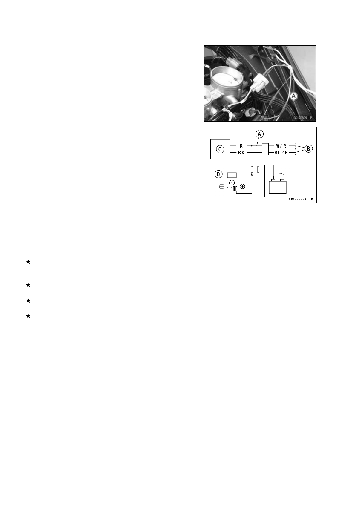
3-118 FUEL SYSTEM (DFI)
Fuel Injectors
Fuel Injector Power Source Voltage Inspection
NOTE
○
Be sure the battery is fully charged.
•
Remove the air cleaner housing (see Air Cleaner Housing
Removal).
•
Turn the ignition switch OFF.
•
Disconnect the injector connector and connect the har-
ness adapter [A] between these connectors as shown.
Main Harness [B]
Fuel Injector #1 [C]
Special Tool - Measuring Adapter: 57001-1700
•
Connect a digital meter [D] to the harness adapter lead.
Fuel Injector Power Source Voltage
Connections to Adapter:
For Fuel Injector #1, #2, #3, #4
Digital Meter (+) R (injector W/R) lead
Digital Meter (–) Battery (–) terminal
•
Measure the power source voltage with the engine
stopped.
•
Turn the engine stop switch to run position.
•
Turn the ignition switch ON.
Power Source Voltage
Standard: Battery Voltage for 3 seconds, and then 0 V
•
Turn the ignition switch OFF.
If the reading is not the standard, check the ECU main
relay and fuel pump relay (see Relay Circuit Inspection in
the Electrical System chapter).
If the main relay and pump relay are normal, check the
wiring (see Fuel Injector Circuit).
If the wiring is good, check the ECU for its ground and
power supply (see ECU Power Supply Inspection).
If the ground and power supply are good, replace the ECU
(see ECU Removal/Installation).
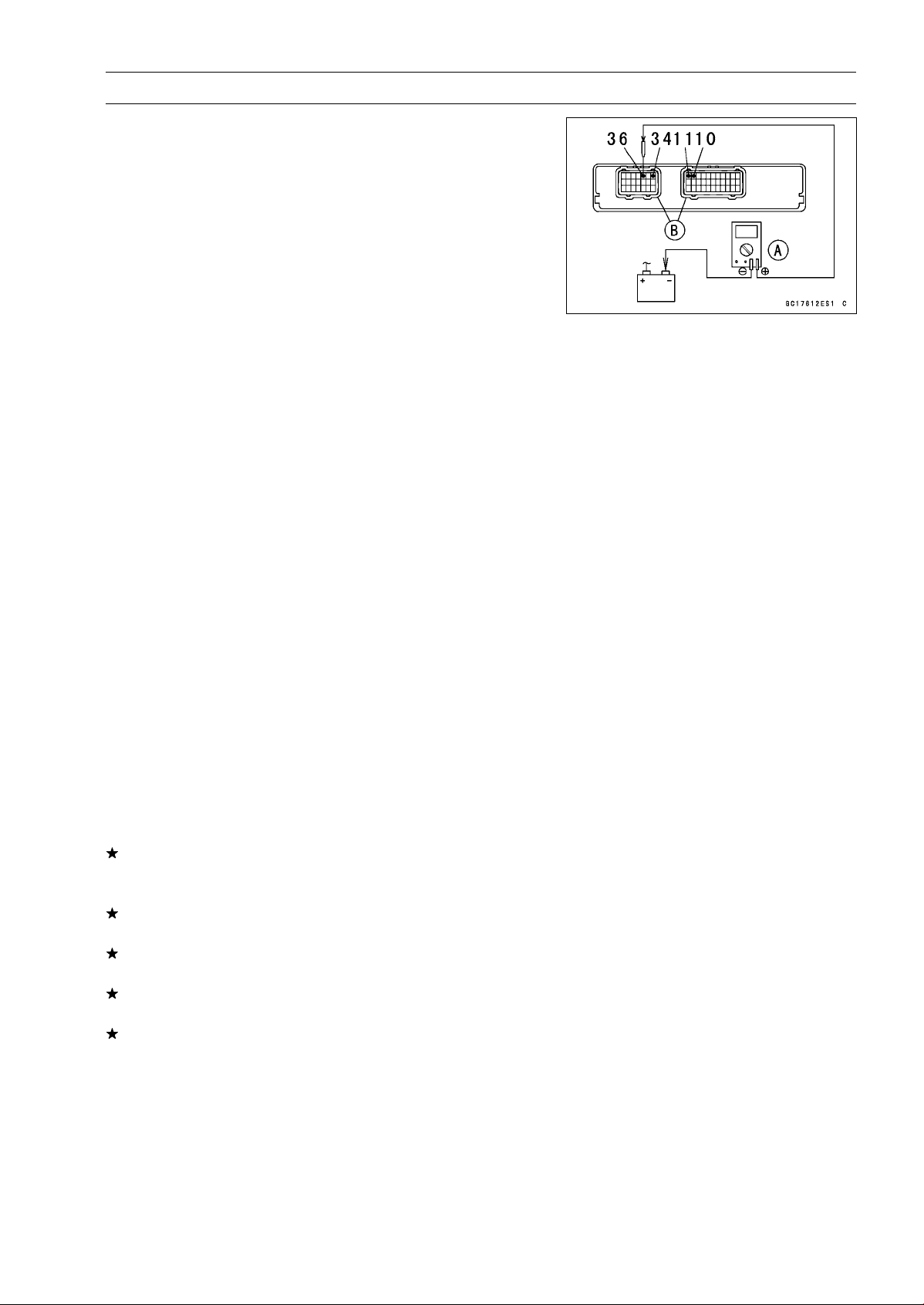
FUEL SYSTEM (DFI) 3-119
Fuel Injectors
Fuel Injector Output Voltage Inspection
NOTE
○
Be sure the battery is fully charged.
•
Turn the ignition switch OFF.
•
Remove the ECU (see ECU Removal).
○
Do not disconnect the ECU connector.
○
Connect the relay box connectors.
•
Connect a digital meter [A] to the connectors [B] with the
needle adapter set.
Special Tool - Needle Adapter Set: 57001-1457
Fuel Injector Output Voltage
Connections to ECU Connector:
For Fuel Injector #1
Digital Meter (+) BL/R lead (ECU terminal 36)
Digital Meter (–) Battery (–) terminal
For Fuel Injector #2
Digital Meter (+) BL/O lead (ECU terminal 34)
Digital Meter (–) Battery (–) terminal
For Fuel Injector #3
Digital Meter (+) BL/W lead (ECU terminal 11)
Digital Meter (–) Battery (–) terminal
For Fuel Injector #4
Digital Meter (+) BL/Y lead (ECU terminal 10)
Digital Meter (–) Battery (–) terminal
•
Measure the output voltage with the engine stopped and
with the connector joined.
•
Turn the engine stop switch to run position.
•
Turn the ignition switch ON.
Output Voltage
Standard: Battery Voltage for 3 seconds, and then 0 V
•
Turn the ignition switch OFF.
If the reading is not the standard, check the ECU main
relay and fuel pump relay (see Relay Circuit Inspection in
the Electrical System chapter).
If the main relay and pump relay are normal, check the
wiring (see Fuel Injector Circuit).
If the wiring is good, check the ECU for its ground and
power supply (see ECU Power Supply Inspection).
If the ground and power supply are good, replace the ECU
(see ECU Removal/Installation).
If there is still no battery voltage, check the fuel injector
resistance (see Fuel Injector Resistance Inspection) and
wiring (see Fuel Injector Circuit).
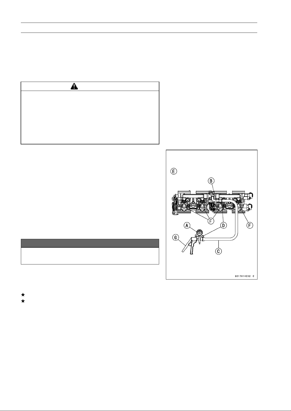
3-120 FUEL SYSTEM (DFI)
Fuel Injectors
Fuel Injector Fuel Line Inspection
•
Remove:
Fuel Tank (see Fuel Tank Removal)
Fuel Hose (see Fuel Tank Removal)
○
Be sure to place a piece of cloth around the fuel outlet
pipe of the fuel pump and the delivery pipe of the throttle
body assy.
WARNING
Fuel is flammable and explosive under certain con-
ditions and can cause severe burns. Be prepared
for fuel spillage; any spilled fuel must be completely
wiped up immediately. When the fuel hose is dis-
connected, fuel spills out from the hose and the
pipe because of residual pressure. Cover the hose
connection with a piece of clean cloth to prevent
fuel spillage.
•
Check the injector fuel line for leakage as follows.
○
Connect a commercially available vacuum/pressure
pump [A] to the nipple of the delivery pipe [B] with the
fuel hose [C] (both ends with the clamps [D]) as shown
in the figure.
Lower Side View [E]
○
Apply soap and water solution to the areas [F] as shown
in the figure.
○
Watching the pressure gauge, squeeze the pump lever
[G], and build up the pressure until the pressure reaches
the maximum pressure.
Injector Fuel Line Maximum Pressure
Standard: 300 kPa (3.06 kgf/cm², 43 psi)
NOTICE
During pressure testing, do not exceed the maxi-
mum pressure for which the system is designed.
○
Watch the gauge for at least 6 seconds.
If the pressure holds steady, the fuel line is good.
If the pressure drops at once or if bubbles are found in the
area, the fuel line is leaking. Replace the delivery pipe
assy, injectors and related parts.
○
Repeat the leak test, and check the fuel line for no leak-
age.
•
Install:
Fuel Hose (see Fuel Tank Installation)
Fuel Tank (see Fuel Tank Installation)
•
Start the engine and check for fuel leakage.
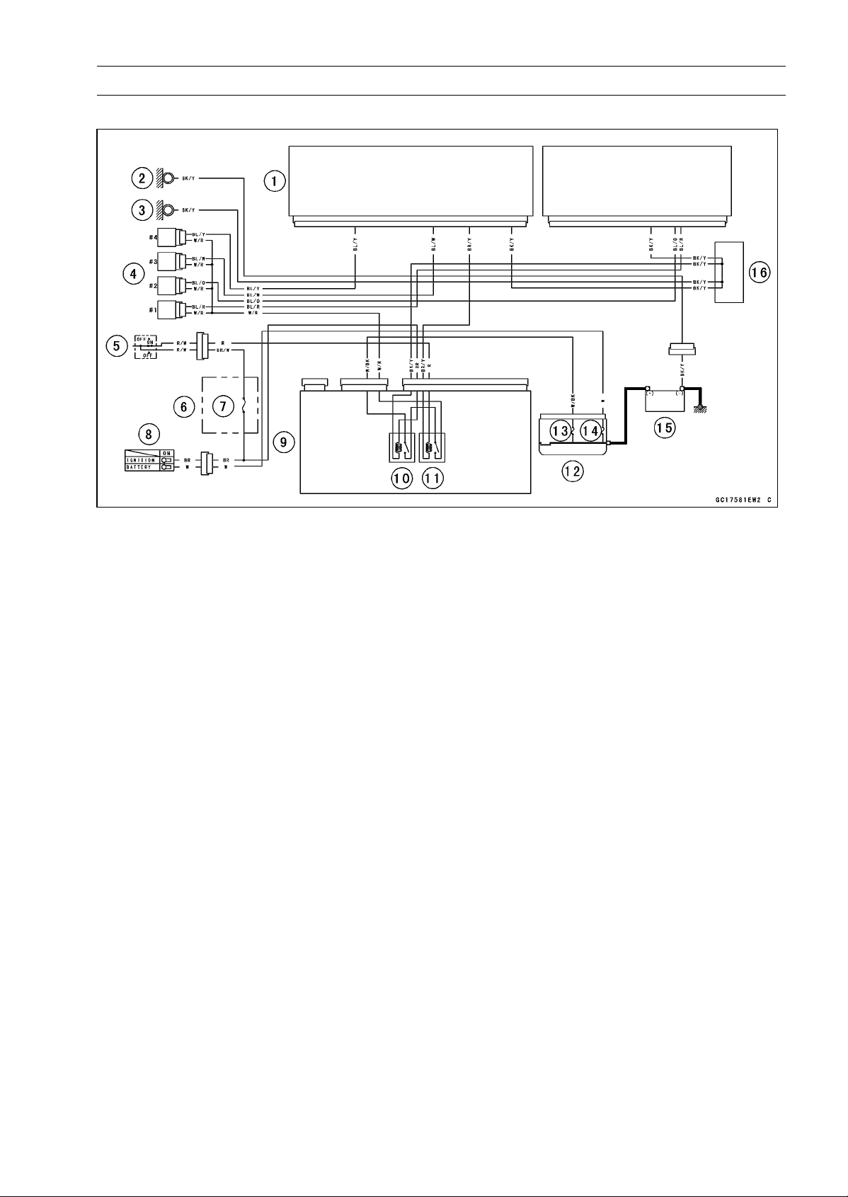
FUEL SYSTEM (DFI) 3-121
Fuel Injectors
Fuel Injector Circuit
1. ECU
2. Frame Ground
3. Meter Ground
4. Fuel Injectors
5. Engine Stop Switch
6. Fuse Box
7. Ignition Fuse 15 A
8. Ignition Switch
9. Meter Unit
10. ECU Main Relay
11. Fuel Pump Relay
12. Starter Relay
13. FI Fuse 15 A
14. Main Fuse 30 A
15. Battery 12 V 8 Ah
16. Water-proof Joint C
3-122 FUEL SYSTEM (DFI)
Throttle Grip and Cables
Free Play Inspection
•
Refer to the Throttle Control System Inspection in the Pe-
riodic Maintenance chapter.
Free Play Adjustment
•
Refer to the Throttle Control System Inspection in the Pe-
riodic Maintenance chapter.
Cable Installation
•
Install the throttle cables in accordance with the Cable,
Wire, and Hose Routing section in the Appendix chapter.
•
Install the lower ends of the throttle cables in the throttle
pulley on the throttle body assy after installing the upper
ends of the throttle cables in the grip.
•
After installation, adjust each cable properly (see Throttle
Control System Inspection in the Periodic Maintenance
chapter).
WARNING
Operation with incorrectly routed or improperly ad-
justed cables could result in an unsafe riding con-
dition. Be sure the cables are routed correctly and
properly adjusted.
Cable Lubrication
•
Refer to the Chassis Parts Lubrication in the Periodic
Maintenance chapter.

FUEL SYSTEM (DFI) 3-123
Throttle Body Assy
Idle Speed Inspection/Adjustment
•
Refer to the Idle Speed Inspection/Adjustment in the Pe-
riodic Maintenance chapter.
Synchronization Inspection/Adjustment
•
Refer to the Engine Vacuum Synchronization Inspection
in the Periodic Maintenance chapter.
Throttle Body Assy Removal
WARNING
Gasoline is extremely flammable and can be ex-
plosive under certain conditions, creating the
potential for serious burns. Make sure the area is
well-ventilated and free from any source of flame
or sparks; this includes any appliance with a pilot
light. Do not smoke. Turn the ignition switch OFF.
Be prepared for fuel spillage; any spilled fuel must
be completely wiped up immediately.
NOTICE
Never drop the throttle body assy, especially on a
hard surface. Such a shock to the body assy can
damage it.
•
Remove:
Air Cleaner Housing (see Air Cleaner Housing Removal)
Fuel Hose (see Fuel Tank Removal)
•
Disconnect:
Intake Air Pressure Sensor #1 Connector [A]
Intake Air Pressure Sensor #2 Connector [B]
Subthrottle Valve Actuator Connector [C]
•
For California and Southeast Asia B1 Models, pull off the
vacuum hose [D].
•
Disconnect:
Main Throttle Sensor Connector [A]
Subthrottle Sensor Connector [B]
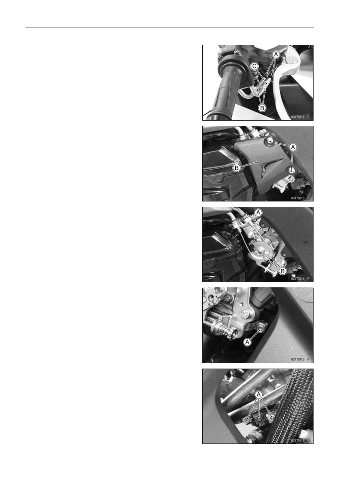
3-124 FUEL SYSTEM (DFI)
Throttle Body Assy
•
Slide the dust covers [A].
•
Loosen the locknuts [B].
•
Turn the adjusters [C] to give the more free play.
•
Remove:
Bolts [A]
Throttle Pulley Cover [B]
•
Remove:
Throttle Cable Holder Clamp [A]
Throttle Cable Lower Ends [B]
•
Loosen the throttle body assy holder clamp bolts [A].
Special Tool - Carburetor Drain Plug Wrench, Hex 3:
57001-1269
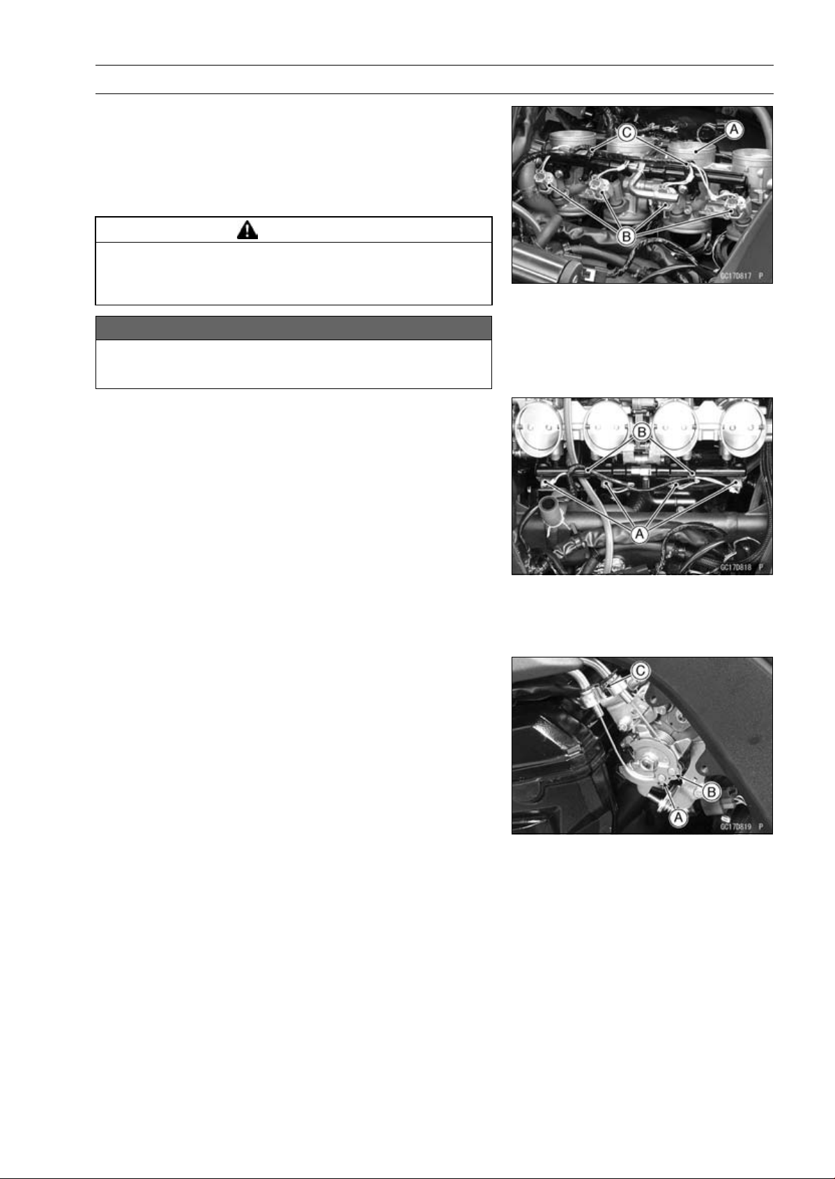
FUEL SYSTEM (DFI) 3-125
Throttle Body Assy
•
Remove the throttle body assy [A] from the throttle body
assy holders.
•
Disconnect the injector connectors [B].
•
Remove the clamps [C].
•
After removing the throttle body assy, stuff pieces of lint
-free, clean cloth into the throttle body assy holders.
WARNING
If dirt or dust is allowed to pass through into the
throttle body assy, the throttle may become stuck,
possibly causing accident.
NOTICE
If dirt gets into the engine, excessive engine wear
and possible engine damage will occur.
Throttle Body Assy Installation
•
Be sure to position the throttle body assy holder clamp in
original position (see Throttle Body Assy Holder Installa-
tion in the Engine Top End chapter).
•
Connect the injector connectors [A].
•
Install the throttle body assy to the throttle body assy hold-
ers.
•
Install the clamps [B].
•
Tighten:
Torque - Throttle Body Assy Holder Clamp Bolts: 2.9 N·m
(0.30 kgf·m, 26 in·lb)
Special Tool - Carburetor Drain Plug Wrench, Hex 3:
57001-1269
•
Apply a thin coat of grease to the throttle cable lower ends.
•
Fit the accelerator cable end [A] and the decelerator cable
end [B] into the throttle pulley.
○
The accelerator cable has a clamp [C].
•
Install the clamp securely.
•
Turn the throttle grip and make sure that the throttle pulley
moves smoothly and return by spring force.
•
Run the leads and hoses correctly (see Cable, Wire, and
Hose Routing section in the Appendix chapter).
•
Adjust:
Throttle Grip Free Play (see Throttle Control System In-
spection in the Periodic Maintenance chapter)
Idle Speed (see Idle Speed Adjustment in the Periodic
Maintenance chapter)
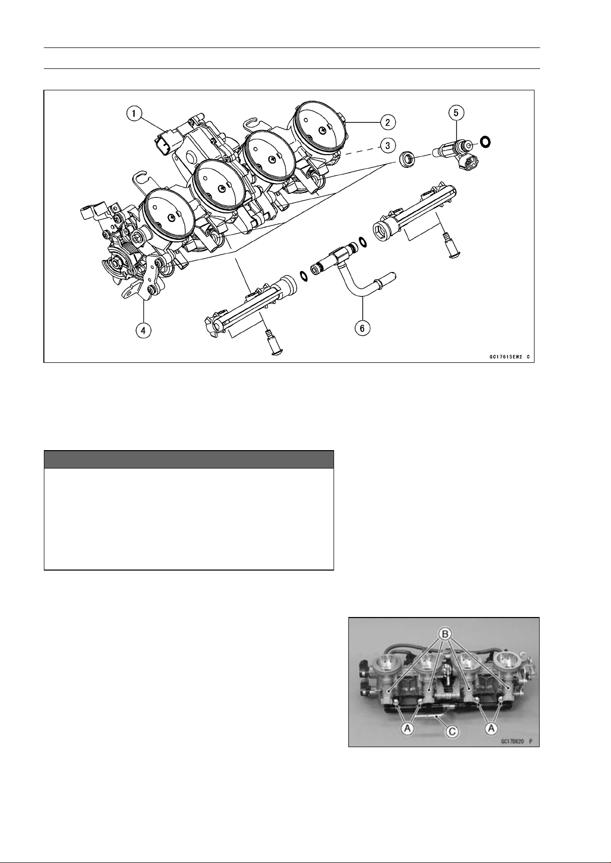
3-126 FUEL SYSTEM (DFI)
Throttle Body Assy
Throttle Body Assy Disassembly
1. Subthrottle Valve Actuator
2. Subthrottle Sensor
3. Main Throttle Sensor
4. Throttle Body Assy
5. Fuel Injectors
6. Delivery Pipe Assy
NOTICE
Do not remove, disassemble or adjust the main
throttle sensor, subthrottle sensor, subthrottle
valve actuator, throttle link mechanism and throttle
body assy, because they are adjust or set surely at
the manufacturer. Adjustment of these parts could
result in poor performance, requiring replacement
of the throttle body assy.
•
Remove the throttle body assy (see Throttle Body Assy
Removal).
•
Remove the delivery pipe assy mounting screws [A] to
pull out the fuel injectors [B] from the throttle body assy
together with the delivery pipe assy [C].
NOTE
○
Do not damage the insertion portions of the injectors
when they are pulled out from the throttle body.
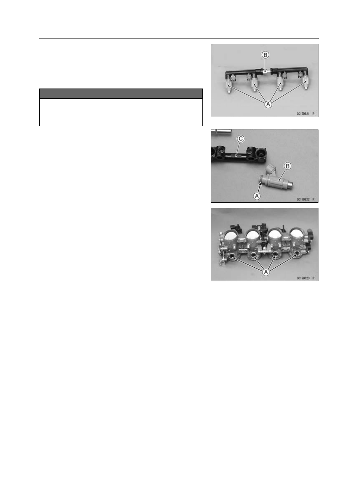
FUEL SYSTEM (DFI) 3-127
Throttle Body Assy
•
Pull out the fuel injectors [A] from the delivery pipe assy
[B].
NOTE
○
Do not damage the insertion portions of the injectors
when they are pulled out from the delivery pipe assy.
NOTICE
Never drop the primary fuel injector, especially on
a hard surface. Such a shock to the injector can
damage it.
Throttle Body Assy Assembly
•
Before assembling, blow away dirt or dust from the throttle
body and delivery pipe assy by applying compressed air.
•
Replace the O-rings [A] of each fuel injector [B] with new
ones.
•
Apply engine oil to the new O-rings, insert them to the
delivery pipe assy [C] and confirm whether the injectors
turn smoothly or not.
•
Replace the dust seals [A] with new ones.
•
Apply engine oil to the new dust seals.
•
Install the fuel injectors along with the delivery pipe assy
to the throttle body.
•
Tighten:
Torque - Delivery Pipe Assy Mounting Screws: 3.4 N·m
(0.35 kgf·m, 30 in·lb)
•
Install the throttle body assy (see Throttle Body Assy In-
stallation).
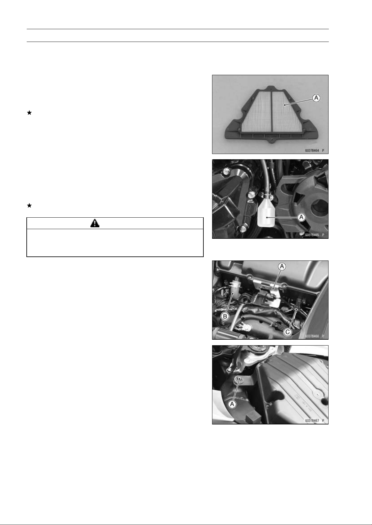
3-128 FUEL SYSTEM (DFI)
Air Cleaner
Air Cleaner Element Removal/Installation
•
Refer to the Air Cleaner Element Replacement in the Pe-
riodic Maintenance chapter.
Air Cleaner Element Inspection
•
Remove the air cleaner element (see Air Cleaner Element
Replacement in the Periodic Maintenance chapter).
•
Visually check the element [A] for tears or breaks.
If the element has any tears or breaks, replace the ele-
ment.
Air Cleaner Oil Draining
A drain hose is connected to the bottom of the air cleaner
to drain water or oil accumulated in the cleaner part.
•
Visually check the catch tank [A] of the drain hose, if the
water or oil accumulates in the tank.
If any water or oil accumulates in the catch tank, remove
the catch tank from the drain hose and drain it.
WARNING
Oil on tires will make them slippery and can cause
an accident and injury. Be sure to reinstall the catch
tank after draining.
Air Cleaner Housing Removal
•
Remove:
Fuel Tank (see Fuel Tank Removal)
Connector Bracket [A]
Breather Hose [B]
•
Disconnect the intake air temperature sensor connector
[C].
•
Remove the bolt [A].
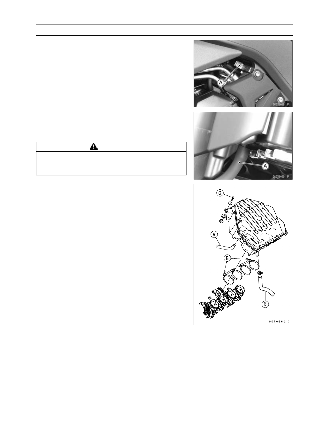
FUEL SYSTEM (DFI) 3-129
Air Cleaner
•
Loosen the both air cleaner duct clamp bolts [A].
•
Lift up the air cleaner housing, and remove the air switch-
ing valve hose [A].
•
After removing the air cleaner housing, cover the clean
cloth on the throttle body assy.
WARNING
If dirt or dust is allowed to pass through into the
throttle body assy, the throttle may become stuck,
possibly causing accident.
Air Cleaner Housing Installation
•
Install the air switching valve hose [A] to the air cleaner
housing.
•
Install the air cleaner housing on the throttle body assy.
○
Install the clamp bolt heads [B] outside as shown in the
figure.
•
Tighten:
Torque - Air Cleaner Duct Clamp Bolts: 2.0 N·m (0.20 kgf·m,
18 in·lb)
•
Tighten the air cleaner housing mounting bolts [C].
•
Install the breather hose [D].
•
Run the leads and hoses correctly (see Cable, Wire, and
Hose Routing section in the Appendix chapter).
•
Install the removed parts (see appropriate chapters).
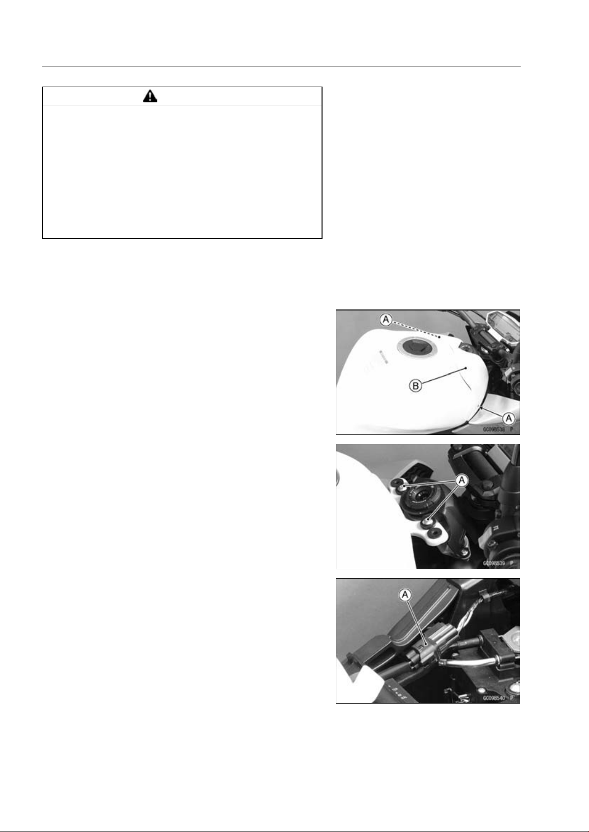
3-130 FUEL SYSTEM (DFI)
Fuel Tank
Fuel Tank Removal
WARNING
Gasoline is extremely flammable and can be ex-
plosive under certain conditions, creating the
potential for serious burns. Make sure the area is
well-ventilated and free from any source of flame
or sparks; this includes any appliance with a pilot
light. Do not smoke. Turn the ignition switch OFF.
Disconnect the battery (–) terminal. To avoid fuel
spills, draw it from the tank when the engine is
cold. Be prepared for fuel spillage; any spilled fuel
must be completely wiped up immediately.
•
Turn the ignition switch OFF.
•
Wait until the engine cools down.
•
Disconnect the battery (–) terminal (see Battery Removal
in the Electrical System chapter).
•
Remove:
Bolts [A]
Fuel Tank Cover [B]
•
Remove:
Front Fuel Tank Bolts [A]
•
Disconnect the fuel pump lead connector [A].
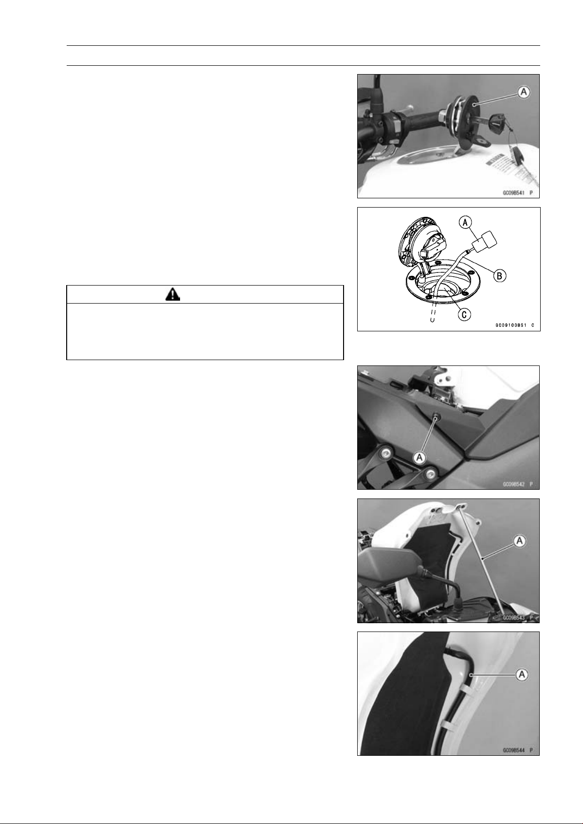
FUEL SYSTEM (DFI) 3-131
Fuel Tank
•
Open the fuel tank cap [A] to lower the pressure in the
tank.
○
During tank removal, keep the tank cap open to release
pressure in the tank. This makes fuel spillage less.
•
Draw the fuel out from the fuel tank with a commercially
available pump [A].
○
Use a soft plastic hose [B] as a pump inlet hose in order
to insert the hose smoothly.
○
Put the hose through the fill opening [C] into the tank and
draw the fuel out.
WARNING
Spilled fuel is flammable and can be explosive un-
der certain conditions. The fuel can not be removed
completely from the fuel tank. Be careful for re-
mained fuel spillage.
•
Remove the both side cover bolts [A].
•
Lift up the fuel tank, and support it with a suitable bar [A].
•
Remove the drain hose [A] from the fuel tank.
•
Be sure to place a piece of cloth around the fuel hose joint.
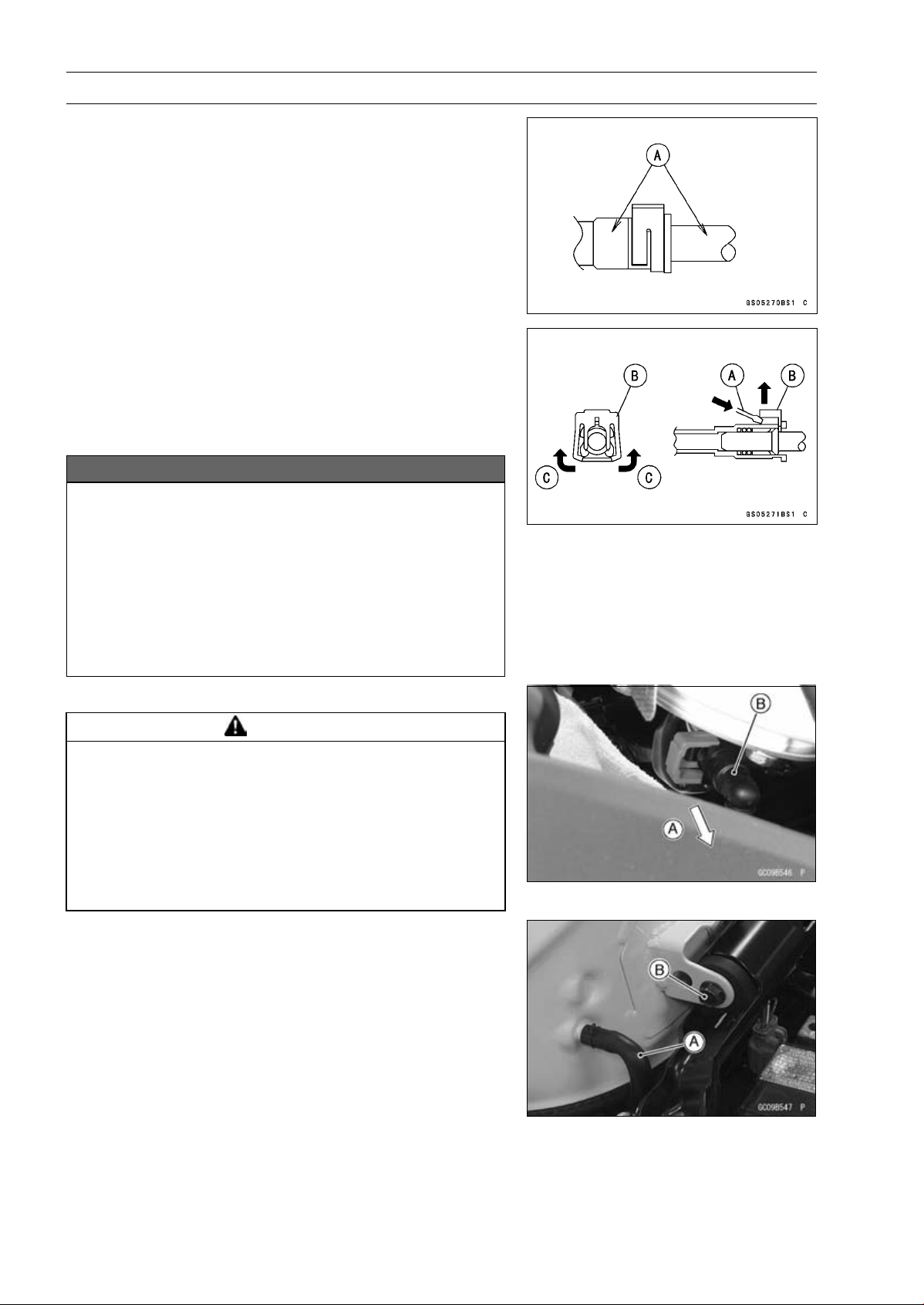
3-132 FUEL SYSTEM (DFI)
Fuel Tank
•
Wipe off the dirt of the surface [A] around the connection
using a cloth or a soft brush.
When removing with standard tip screwdriver
•
Insert the standard tip screwdriver [A] into slit on the joint
lock [B].
•
Turn the driver to disconnect the joint lock.
When removing with fingers
•
Open and push up [C] the joint lock with your fingers.
NOTICE
Prying or excessively widening the joint lock ends
for fuel hose removal will permanently deform the
joint lock, resulting in a loose or incomplete lock
that may allow fuel to leak and create the potential
for a fire explosion. To prevent fire or explosion
from a damaged joint lock, do not pry or excessively
widen the joint lock ends when removing the fuel
hose. The joint lock has a retaining edge that locks
around the housing.
•
Pull [A] the fuel hose joint [B] out of the outlet pipe.
WARNING
Fuel is flammable and explosive under certain con-
ditions and can cause severe burns. Be prepared
for fuel spillage; any spilled fuel must be completely
wiped up immediately. When the fuel hose is dis-
connected, fuel spills out from the hose and the
pipe because of residual pressure. Cover the hose
connection with a piece of clean cloth to prevent
fuel spillage.
•
Remove the bar which supported fuel tank.
•
For other than CAL, SEA-B1 and TH models, remove the
fuel tank breather hose [A] and rear fuel tank bolt [B].
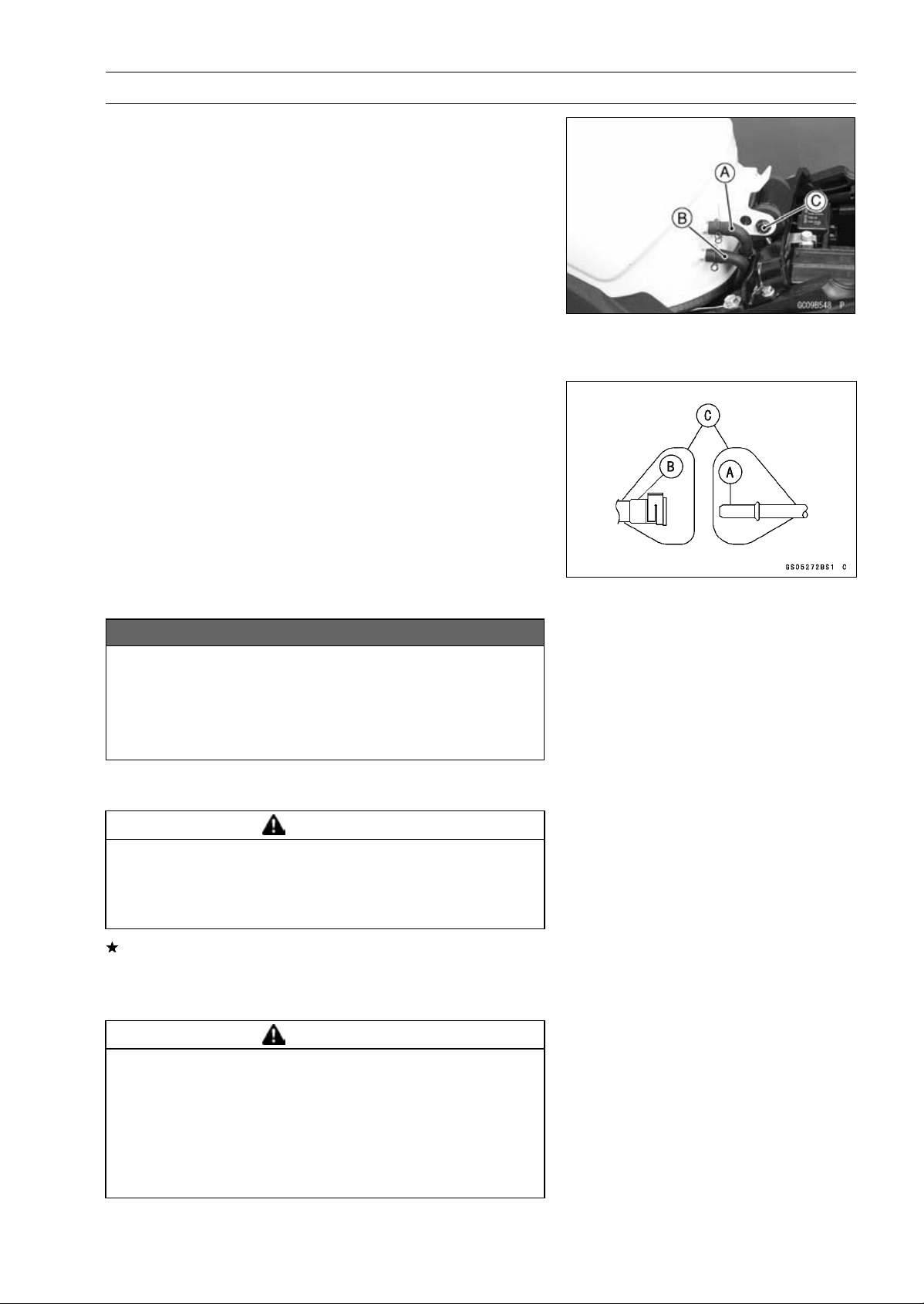
FUEL SYSTEM (DFI) 3-133
Fuel Tank
•
For the CAL, SEA-B1 and TH models, remove the follow-
ing.
Fuel Return Hose [A] (red)
Fuel Tank Breather Hose [B] (blue)
Rear Fuel Tank Bolt [C]
•
Remove the fuel tank, and place a it on a flat surface.
○
Do not apply the load to the fuel pipe of the fuel pump.
•
Cleanthepipe[A].
•
Cover the pipe and the hose joint [B] with the vinyl bags
[C] to keep it clean.
•
Close the fuel tank cap.
•
For the CAL, SEA-B1 and TH models, note the following.
NOTICE
For the CAL, SEA-B1 and TH models, if gasoline,
solvent, water or any other liquid enters the can-
ister, the canister’s vapor absorbing capacity is
greatly reduced. If the canister does become con-
taminated, replace it with a new one.
○
Be sure to plug the evaporative fuel return hose to prevent
fuel spilling before fuel tank removal.
WARNING
Spilled fuel is flammable and can be explosive un-
der certain conditions. For California, Southeast
Asia B1 and Thailand models, be careful not to spill
fuel through the return hose.
If liquid or gasoline flows into the breather hose, remove
the hose and blow it clean with compressed air.
○
Be careful of fuel spillage from the fuel tank since fuel still
remains in the fuel tank and fuel pump.
WARNING
Gasoline is extremely flammable and can be explo-
sive under certain conditions, creating the poten-
tial for serious burns. Store the fuel tank in an area
which is well-ventilated and free from any source of
flame or sparks. Do not smoke in this area. Place
the fuel tank on a flat surface and plug the fuel pipes
to prevent fuel leakage.
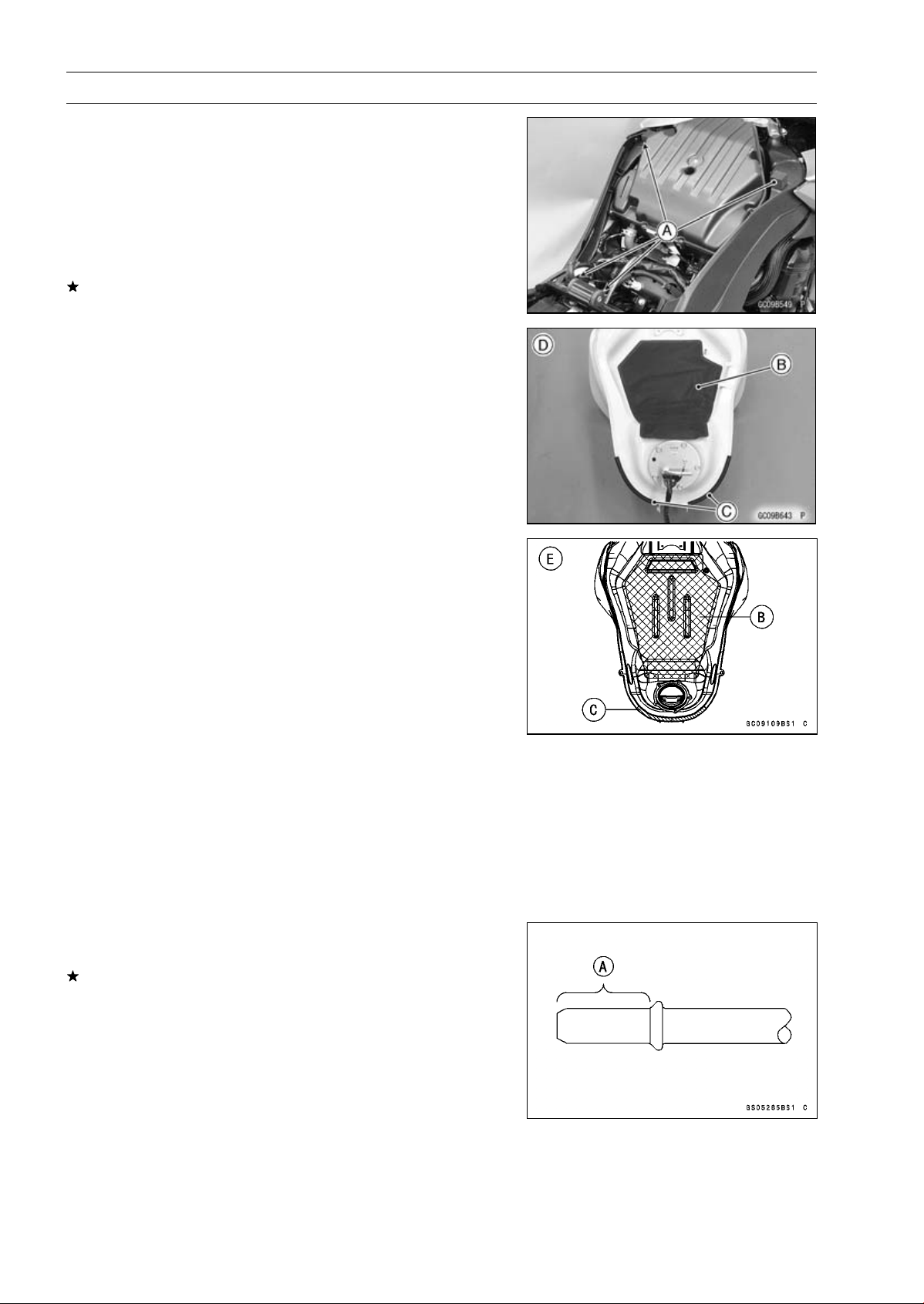
3-134 FUEL SYSTEM (DFI)
Fuel Tank
Fuel Tank Installation
•
Note the above WARNING (see Fuel Tank Removal).
•
Run the hoses correctly (see Cable, Wire, and Hose Rout-
ing section in the Appendix chapter).
•
Check that the dampers [A], pad [B] and trims [C] are in
place on the frame and the fuel tank.
Frame No. ∼ JKAZRT00DA017291 [D]
Frame No. JKAZRT00DA017292 ∼ [E]
If the dampers, pad or trims are damaged or deteriorated,
replace them.
•
Install the drain hose and clamp securely.
•
Run the hoses correctly (see Cable, Wire, and Hose Rout-
ing section in the Appendix chapter).
•
For the CAL, SEA-B1 and TH models, note the following.
○
To prevent the gasoline from flowing into or out of the
canister, hold the separator perpendicular to the ground.
○
Connect the hoses according to the diagram of the evap-
orative emission control system. Make sure they do not
get pinched or kinked.
○
Run hoses with a minimum of bending so that the air or
vapor will not be obstructed.
•
Remove the vinyl bag on the pipe and fuel hose joint.
•
Check the joint lock for deformation and wear.
If the joint lock is deformed, replace the fuel hose with a
new one.
•
Check that there are no flaws, burrs, and adhesion of
foreign materials on the delivery pipe [A].
•
Apply engine oil to the pipe.
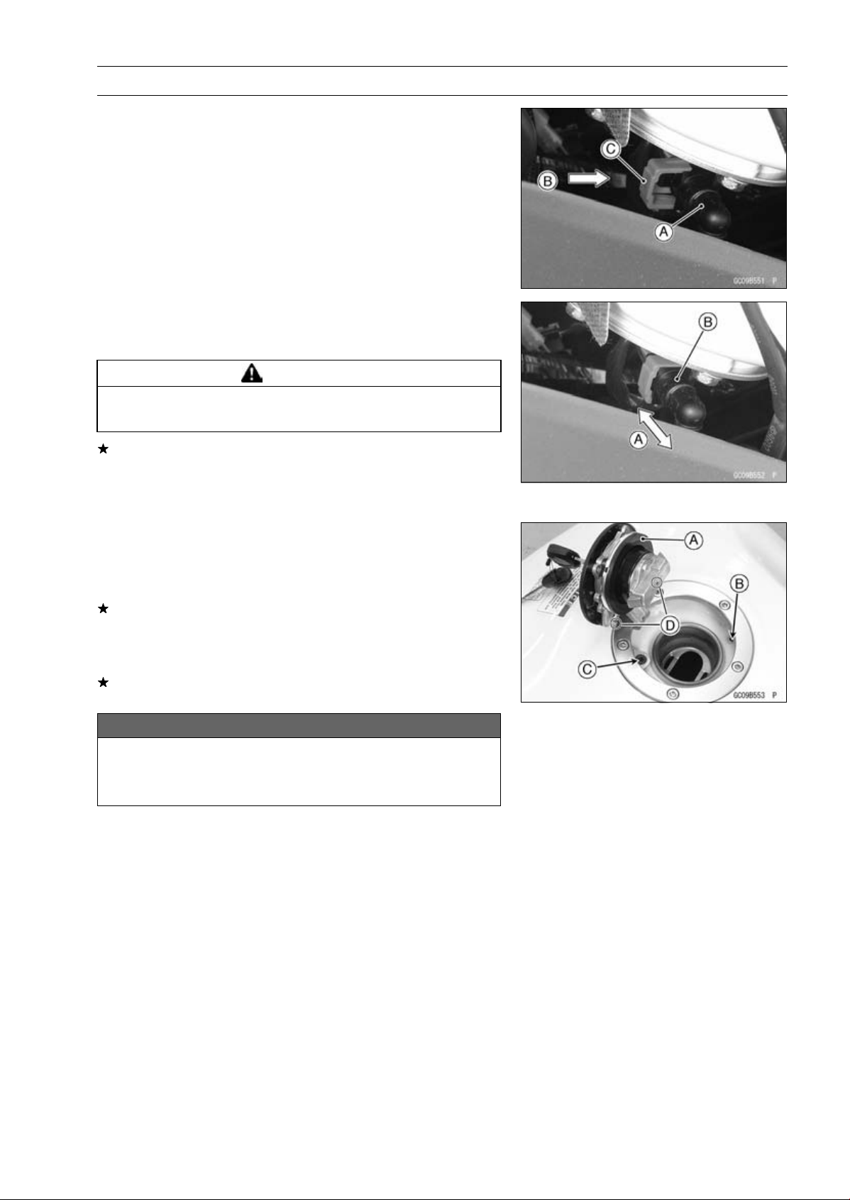
FUEL SYSTEM (DFI) 3-135
Fuel Tank
•
Insert the fuel hose joint [A] straight onto the fuel outlet
pipe until the hose joint clicks.
•
Push [B] the joint lock [C] until the hose joint clicks.
•
Push and pull [A] the hose joint [B] back and forth more
than two times, and make sure it is locked and does not
come off.
WARNING
Make sure the hose joint is installed correctly on the
delivery pipe or the fuel could leak.
If it comes off, reinstall the hose joint.
•
Connect the fuel pump lead connector and the battery (–)
terminal (see Battery Installation in the Electrical System
chapter).
Fuel Tank and Cap Inspection
•
Open the tank cap.
•
Visually inspect the gasket [A] on the tank cap for any
damage.
Replace the tank cap if gasket is damaged.
•
Check to see if the water drain pipe [B] and fuel breather
pipe [C] in the tank are not clogged. Check the tank cap
breather also.
If they are clogged, remove the tank and drain it, and then
blow the breather free with compressed air.
NOTICE
Do not apply compressed air to the air vent holes
[D] in the tank cap. This could cause damage and
clogging of the labyrinth in the cap.

3-136 FUEL SYSTEM (DFI)
Fuel Tank
Fuel Tank Cleaning
WARNING
Gasoline and low flash-point solvents can be
flammable and/or explosive and cause severe
burns. Clean the tank in a well-ventilated area, and
take care that there are no sparks or flame any-
where near the working area. Do not use gasoline
or low flash-point solvents to clean the tank.
•
Remove:
Fuel Tank (see Fuel Tank Removal)
Fuel Pump (see Fuel Pump Removal)
•
Pour some high flash-point solvent into the fuel tank and
shake the tank to remove dirt and fuel deposits.
•
Draw the solvent out of the fuel tank.
•
Dry the tank with compressed air.
•
Install:
Fuel Pump (see Fuel Pump Installation)
Fuel Tank (see Fuel Tank Installation)
FUEL SYSTEM (DFI) 3-137
Evaporative Emission Control System (CAL, SEA-B1 and TH Models)
The Evaporative Emission Control System routes fuel va-
pors from the fuel system into the running engine or stores
the vapors in a canister when the engine is stopped. Al-
though no adjustments are required, a thorough visual in-
spection must be made at the intervals specified by the Pe-
riodic Maintenance Chart.
Parts Removal/Installation
WARNING
Gasoline is extremely flammable and can be ex-
plosive under certain conditions. Turn the ignition
switch OFF. Do not smoke. Make sure the area is
well-ventilated and free from any source of flame
or sparks; this includes any appliance with a pilot
light.
NOTICE
If gasoline, solvent, water or any other liquid enters
the canister, the canister’s vapor absorbing capac-
ity is greatly reduced. If the canister does become
contaminated, replace it with a new one.
•
To prevent the gasoline from flowing into or out of the
canister, hold the separator perpendicular to the ground.
•
Connect the hoses according to the diagram of the sys-
tem (see Cable, Wire, and Hose Routing section in the
Appendix chapter). Make sure they do not get pinched or
kinked.
Hose Inspection
•
Refer to the Evaporative Emission Control System In-
spection in the Periodic Maintenance chapter.
Separator Inspection
•
Refer to the Evaporative Emission Control System In-
spection in the Periodic Maintenance chapter.
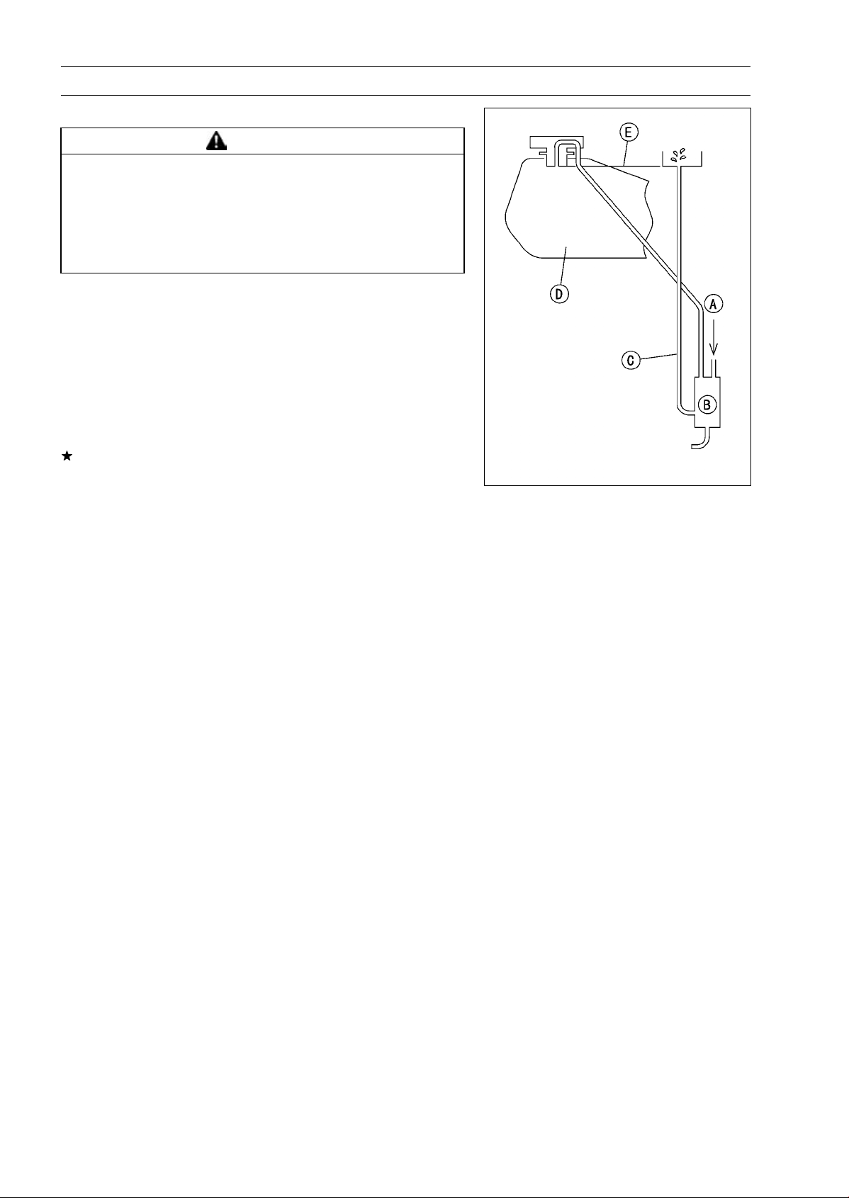
3-138 FUEL SYSTEM (DFI)
Evaporative Emission Control System (CAL, SEA-B1 and TH Models)
Separator Operation Test
WARNING
Gasoline is extremely flammable and can be ex-
plosive under certain conditions. Turn the ignition
switch OFF. Do not smoke. Make sure the area is
well-ventilated and free from any source of flame
or sparks; this includes any appliance with a pilot
light.
•
Connect the hoses to the separator, and install the sepa-
rator on the motorcycle.
•
Disconnect the breather hose from the separator, and in-
ject about 20 mL (0.68 US oz.) of gasoline [A] into the
separator [B] through the hose fitting.
•
Disconnect the fuel return hose [C] from the fuel tank [D].
•
Run the open end of the return hose into the container
and hold it level with the tank top [E].
•
Start the engine, and let it idle.
If the gasoline in the separator comes out of the hose, the
separator works well. If it does not, replace the separator
with a new one.
Canister Inspection
•
Refer to the Evaporative Emission Control System (CAL
and SEA-B1 Models) Inspection in the Periodic Mainte-
nance chapter.
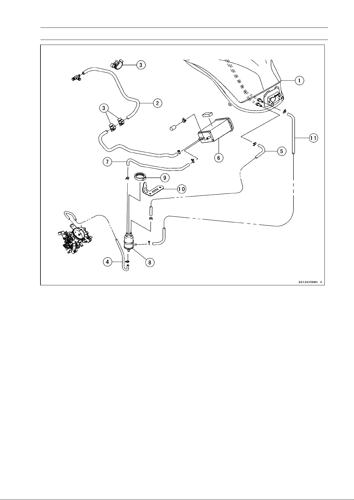
FUEL SYSTEM (DFI) 3-139
Evaporative Emission Control System (CAL, SEA-B1 and TH Models)
1. Fuel Tank
2. Green Hose (Purge)
3. Clamps
4. White Hose (Vacuum)
5. Blue Hose (Breather)
6. Canister
7. Blue Hose (Breather)
8. Separator
9. Damper (for Separator)
10. Bracket (for Separator)
11. Red Hose (Return)


COOLING SYSTEM 4-1
4
Cooling System
Table of Contents
Exploded View........................................................................................................................ 4-2
Coolant Flow Chart................................................................................................................. 4-4
Specifications ......................................................................................................................... 4-6
Special Tools ......................................................................................................................... 4-7
Coolant ................................................................................................................................... 4-8
Coolant Deterioration Inspection....................................................................................... 4-8
Coolant Level Inspection................................................................................................... 4-8
Coolant Draining ............................................................................................................... 4-8
Coolant Filling ................................................................................................................... 4-8
Pressure Testing ............................................................................................................... 4-8
Cooling System Flushing .................................................................................................. 4-9
Coolant Reserve Tank Removal/Installation ..................................................................... 4-9
Water Pump............................................................................................................................ 4-10
Water Pump Removal....................................................................................................... 4-10
Water Pump Installation.................................................................................................... 4-10
Water Pump Inspection..................................................................................................... 4-12
Water Pump Impeller Disassembly/Assembly .................................................................. 4-12
Water Pump Impeller Inspection....................................................................................... 4-12
Water Pump Housing Disassembly .................................................................................. 4-12
Water Pump Housing Assembly ....................................................................................... 4-13
Mechanical Seal Inspection .............................................................................................. 4-13
Radiator.................................................................................................................................. 4-14
Radiator and Radiator Fan Removal ................................................................................ 4-14
Radiator and Radiator Fan Installation ............................................................................. 4-16
Radiator Inspection........................................................................................................... 4-16
Radiator Cap Inspection ................................................................................................... 4-17
Radiator Filler Neck Inspection......................................................................................... 4-17
Thermostat ............................................................................................................................. 4-18
Thermostat Removal......................................................................................................... 4-18
Thermostat Installation...................................................................................................... 4-18
Thermostat Inspection ...................................................................................................... 4-19
Hose and Pipes ...................................................................................................................... 4-20
Hose Installation ............................................................................................................... 4-20
Hose Inspection ................................................................................................................ 4-20
Water Temperature Sensor .................................................................................................... 4-21
Water Temperature Sensor Removal/Installation ............................................................. 4-21
Water Temperature Sensor Inspection ............................................................................. 4-21
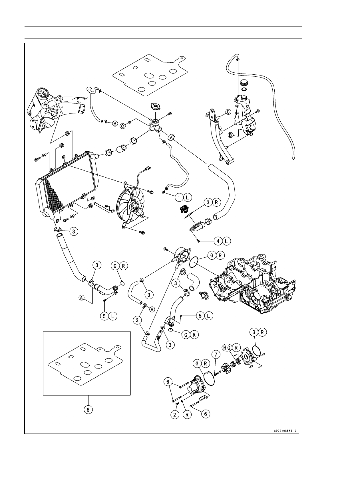
4-2 COOLING SYSTEM
Exploded View

COOLING SYSTEM 4-3
Exploded View
Torque
No. Fastener
N·m kgf·m ft·lb
Remarks
1 Coolant By-pass Fitting Bolt 8.8 0.90 78 in·lb L
2 Coolant Drain Bolt 11 1.1 97 in·lb
3
Radiator (Water) Hose Clamp Screws
2.9 0.30 26 in·lb
4 Thermostat Housing Bolts 5.9 0.60 52 in·lb L
5 Water Pipe Bolts 12 1.2 106 in·lb L
6 Water Pump Cover Bolts 11 1.1 97 in·lb
7 Water Pump Impeller Bolt 9.8 1.0 87 in·lb
8. Engine No. ∼ ZRT00DE003462
G: Apply grease.
HG: Apply high-temperature grease.
L: Apply a non-permanent locking agent.
R: Replacement Parts
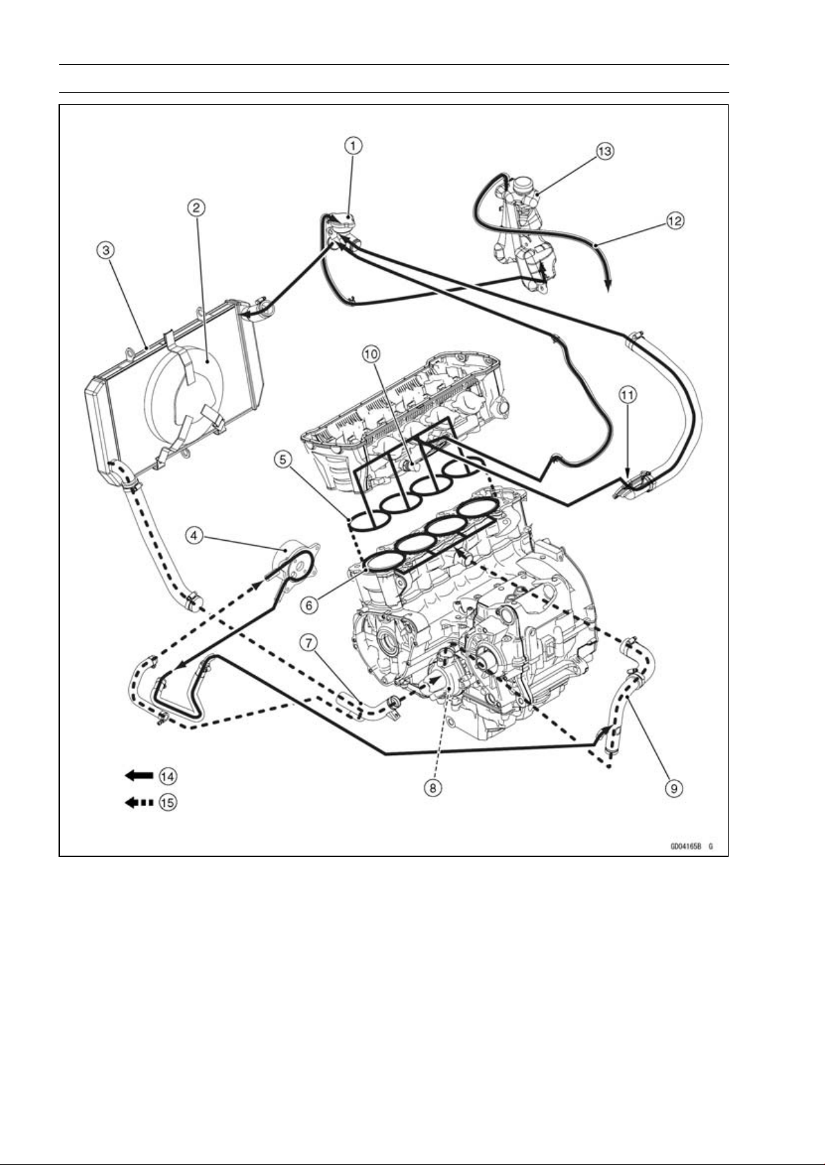
4-4 COOLING SYSTEM
Coolant Flow Chart
1. Radiator Cap
2. Radiator Fan
3. Radiator
4. Oil Cooler
5. Cylinder Head Jacket
6. Cylinder Jacket
7. Inlet Pipe
8. Water Pump
9. Outlet Pipe
10. Water Temperature Sensor
11. Thermostat Housing
12. Reserve Tank Overflow Hose
13. Reserve Tank
14. Hot Coolant
15. Cold Coolant

COOLING SYSTEM 4-5
Coolant Flow Chart
Permanent type antifreeze is used as a coolant to protect the cooling system from rust and corro-
sion. When the engine starts, the water pump turns and the coolant circulates.
The thermostat is a wax pellet type which opens or closes with coolant temperature changes. The
thermostat continuously changes its valve opening to keep the coolant temperature at the proper level.
When coolant temperature is less than 55°C (131°F), the thermostat closes so that the coolant flow
is restricted through the air bleeder hole, causing the engine to warm up more quickly. When coolant
temperature is more than 58 ∼ 62°C (136 ∼ 144°F), the thermostat opens and the coolant flows.
When the coolant temperature goes up beyond 100°C (212°F), the radiator fan relay conducts to
operate the radiator fan. The radiator fan draws air through the radiator core when there is not suffi-
cient air flow such as at low speeds. This increases up the cooling action of the radiator. When the
coolant temperature is below 97.5°C (208°F), the fan relay opens and the radiator fan stops.
In this way, this system controls the engine temperature within narrow limits where the engine op-
erates most efficiently even if the engine load varies.
The system is pressurized by the radiator cap to suppress boiling and the resultant air bubbles
which can cause engine overheating. As the engine warms up, the coolant in the radiator and the
water jacket expands. The excess coolant flows through the radiator cap and hose to the reserve tank
to be stored there temporarily. Conversely, as the engine cools down, the coolant in the radiator and
the water jacket contracts, and the stored coolant flows back to the radiator from the reserve tank.
The radiator cap has two valves. One is a pressure valve which holds the pressure in the system
when the engine is running. When the pressure exceeds 93 ∼ 123 kPa (0.95 ∼ 1.25 kgf/cm², 13 ∼ 18
psi), the pressure valve opens and releases the pressure to the reserve tank. As soon as pressure
escapes, the valve closes, and keeps the pressure at 93 ∼ 123 kPa (0.95 ∼ 1.25 kgf/cm², 13 ∼ 18 psi).
When the engine cools down, another small valve (vacuum valve) in the cap opens. As the coolant
cools, the coolant contracts to form a vacuum in the system. The vacuum valve opens and allows the
coolant from the reserve tank to enter the radiator.
4-6 COOLING SYSTEM
Specifications
Item Standard
Coolant Provided when Shipping
Type (Recommended) Permanent type of antifreeze (soft water and ethylene glycol
plus corrosion and rust inhibitor chemicals for aluminum
engines and radiators)
Color Green
Mixed Ratio Soft water 50%, coolant 50%
Freezing Point −35°C (−31°F)
Total Amount 2.9 L (3.1 US qt) (reserve tank full level, including radiator
and engine)
Radiator Cap
Relief Pressure 93 ∼ 123 kPa (0.95 ∼ 1.25 kgf/cm², 13 ∼ 18 psi)
Thermostat
Valve Opening Temperature 58 ∼ 62°C (136 ∼ 144°F)
Valve Full Opening Lift 8 mm (0.31 in.) or more at 75°C (167°F)
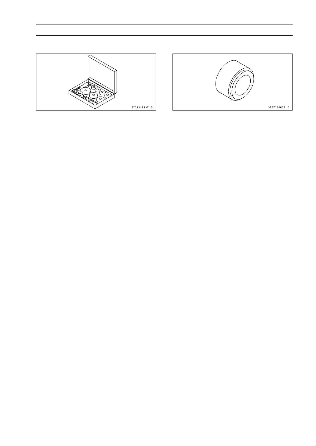
COOLING SYSTEM 4-7
Special Tools
Bearing Driver Set:
57001-1129
Oil Seal Driver:
57001-1660
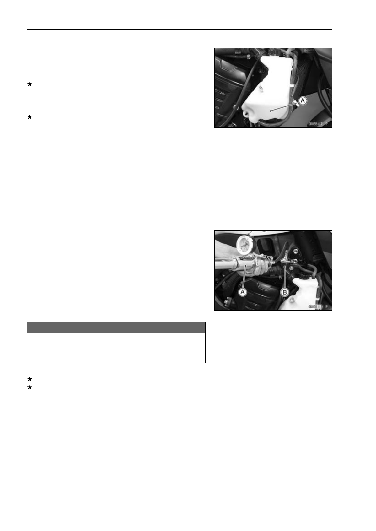
4-8 COOLING SYSTEM
Coolant
Coolant Deterioration Inspection
•
Remove the right center fairing (see Center Fairing Re-
moval in the Frame chapter).
•
Visually inspect the coolant [A] in the reserve tank.
If whitish cotton-like wafts are observed, aluminum parts
in the cooling system are corroded. If the coolant is
brown, iron or steel parts are rusting. In either case, flush
the cooling system.
If the coolant gives off an abnormal smell, check for a
cooling system leak. It may be caused by exhaust gas
leaking into the cooling system.
Coolant Level Inspection
•
Refer to the Coolant Level in the Periodic Maintenance
chapter.
Coolant Draining
•
Refer to the Coolant Change in the Periodic Maintenance
chapter.
Coolant Filling
•
Refer to the Coolant Change in the Periodic Maintenance
chapter.
Pressure Testing
•
Remove the left center fairing (see Center Fairing Re-
moval in the Frame chapter).
•
Remove the radiator cap, and install a cooling system
pressure tester [A] on the filler neck [B].
NOTE
○
Wet the cap sealing surfaces with water or coolant to
prevent pressure leaks.
•
Build up pressure in the system carefully until the pres-
sure reaches 123 kPa (1.25 kgf/cm², 18 psi).
NOTICE
During pressure testing, do not exceed the pres-
sure for which the system is designed. The maxi-
mum pressure is 123 kPa (1.25 kgf/cm², 18 psi).
•
Watch the gauge for at least 6 seconds.
If the pressure holds steady, the system is all right.
If the pressure drops and no external source is found,
check for internal leaks. Droplets in the engine oil indicate
internal leakage. Check the cylinder head gasket and the
water pump.
•
Remove the pressure tester, replenish the coolant, and
install the radiator cap.

COOLING SYSTEM 4-9
Coolant
Cooling System Flushing
Over a period of time, the cooling system accumulates
rust, scale, and lime in the water jacket and radiator. When
this accumulation is suspected or observed, flush the cool-
ing system. If this accumulation is not removed, it will clog
up the water passage and considerable reduce the effi-
ciency of the cooling system.
•
Drain the cooling system (see Coolant Change in the Pe-
riodic Maintenance chapter).
•
Fill the cooling system with fresh water mixed with a flush-
ing compound.
NOTICE
Do not use a flushing compound which is harmful to
the aluminum engine and radiator. Carefully follow
the instructions supplied by the manufacturer of the
cleaning product.
•
Warm up the engine, and run it at normal operating tem-
perature for about ten minutes.
•
Stop the engine, and drain the cooling system.
•
Fill the system with fresh water.
•
Warm up the engine and drain the system.
•
Repeat the previous two steps once more.
•
Fill the system with a permanent type coolant and bleed
the air from the system (see Coolant Change in the Peri-
odic Maintenance chapter).
Coolant Reserve Tank Removal/Installation
•
The coolant reserve tank is removed and installed dur-
ing coolant change (see Coolant Change in the Periodic
Maintenance chapter).
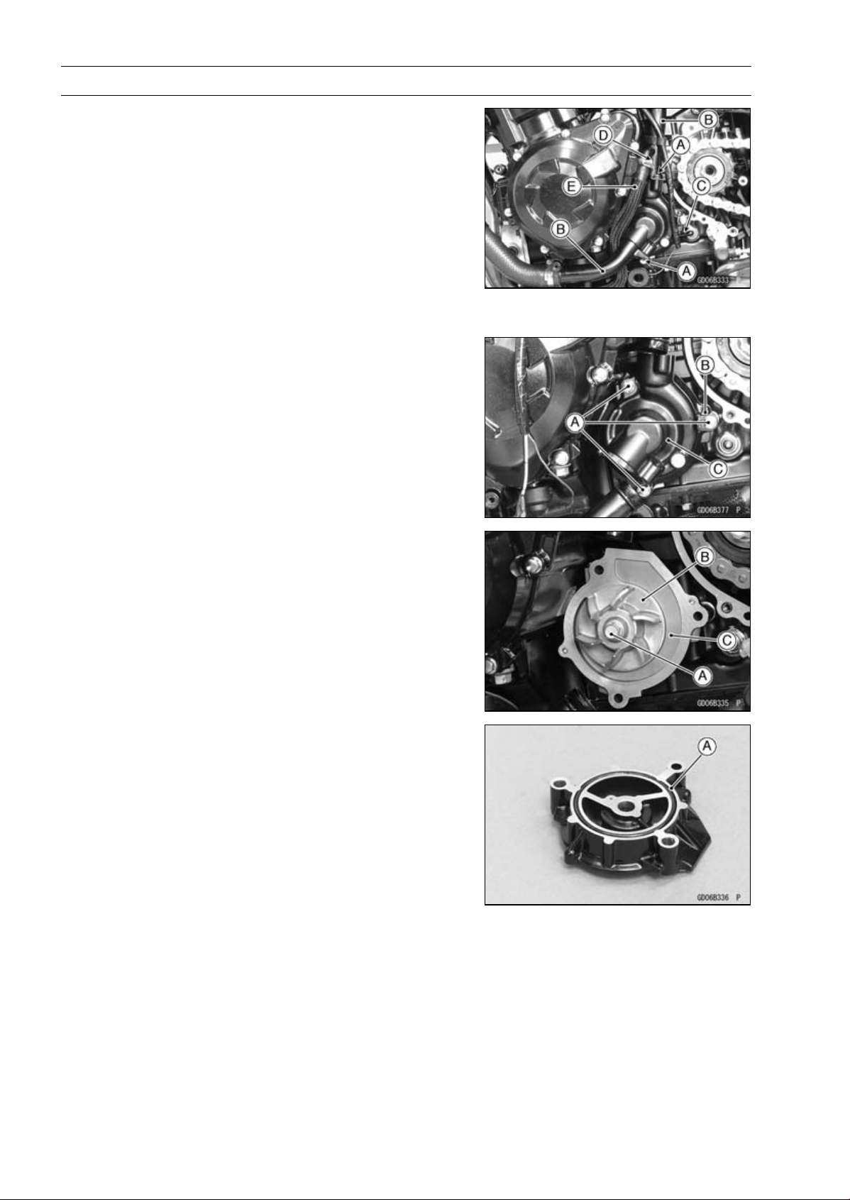
4-10 COOLING SYSTEM
Water Pump
Water Pump Removal
•
Drain:
Coolant (see Coolant Change in the Periodic Mainte-
nance chapter)
Engine Oil (see Engine Oil Change in the Periodic Main-
tenance chapter)
•
Remove the engine sprocket cover (see Engine Sprocket
Cover Removal in the Final Drive chapter).
•
Remove the water pipe bolts [A] to pull out the water pipes
[B] from the water pump cover.
•
Disconnect the neutral switch connector [C].
•
Loosen the clamp bolt [D] to remove the water hose [E].
•
Remove:
Water Pump Cover Bolts [A] and Clamp [B]
Water Pump Cover [C]
•
Remove:
Water Pump Impeller Bolt [A] and Washer
WaterPumpImpeller[B]
Water Pump Housing [C]
Water Pump Installation
•
Replace the O-ring [A] with a new one, and install it.
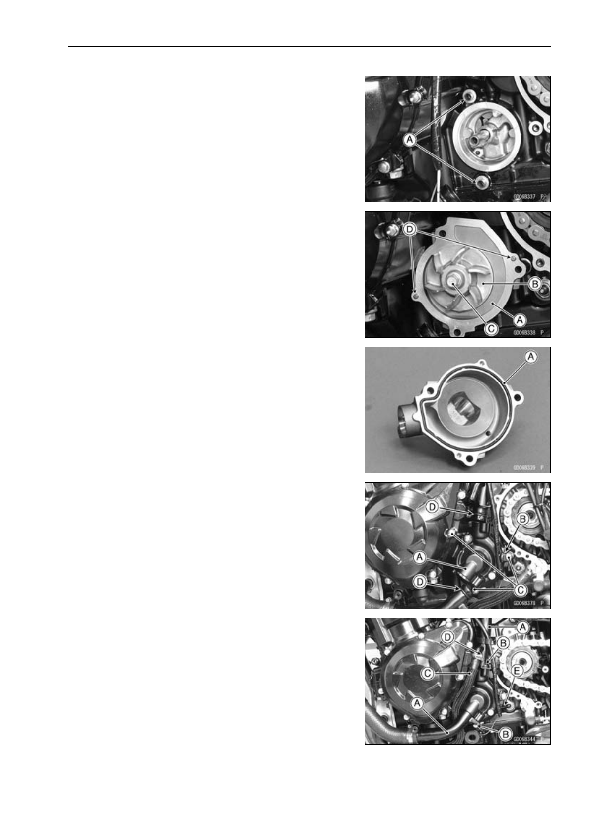
COOLING SYSTEM 4-11
Water Pump
•
Be sure to install the dowel pins [A].
•
Install:
Water Pump Housing [A]
Water Pump Impeller [B]
•
Tighten:
Torque - Water Pump Impeller Bolt [C]: 9.8 N·m (1.0 kgf·m,
87 in·lb)
•
Be sure to install the dowel pins [D].
•
Replace the O-ring [A] with a new one, and install it.
•
Install the water pump cover [A] and the clamp.
○
Touch the clamp to the boss [B] of the water pump cover.
•
Tighten:
Torque - Water Pump Cover Bolts [C]: 11 N·m (1.1 kgf·m, 97
in·lb)
•
Replace the O-ring [D] with new ones.
•
Install the water pipes [A] to the water pump cover.
•
Apply a non-parmanent locking agent to the threads of
the water pipe bolts [B], and tighten them.
Torque - Water Pipe Bolts: 12 N·m (1.2 kgf·m, 106 in·lb)
•
Install the water hose [C].
•
Tighten:
Torque - Water Hose Clamp Screw [D]: 2.9 N·m (0.30 kgf·m,
26 in·lb)
•
Connect the neutral switch connector [E].
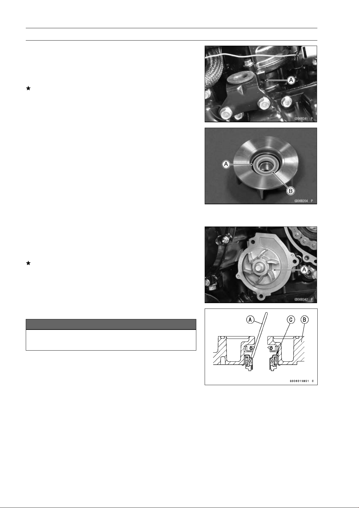
4-12 COOLING SYSTEM
Water Pump
Water Pump Inspection
•
Remove the left lower fairing (see Lower Fairing Removal
in the Frame chapter).
•
Check the drainage outlet passage [A] at the bottom of
the water pump body for coolant leaks.
If the mechanical seal is damaged, the coolant leaks
through the seal and drains through the passage. Re-
place the mechanical seal unit.
Water Pump Impeller Disassembly/Assembly
•
Remove the water pump impeller (see Water Pump Re-
moval).
•
The sealing seat and rubber seal may be removed easily
by hand.
•
Apply coolant around the surfaces of the rubber seal and
sealing seat.
•
Install the rubber seal [A] and sealing seat [B] into the
impeller by pressing them by hand until the seat stops at
the bottom of the hole.
•
Install the water pump impeller (see Water Pump Instal-
lation).
Water Pump Impeller Inspection
•
Remove the water pump cover (see Water Pump Re-
moval).
•
Visually inspect the water pump impeller [A].
If the surface is corroded or if the blades are damaged,
replace the impeller.
Water Pump Housing Disassembly
NOTICE
Do not damage the hole wall of the water pump
housing.
•
Insert a bar [A] into the pump housing [B], and hammer
evenly around the circumference of the mechanical seal
bottom [C].
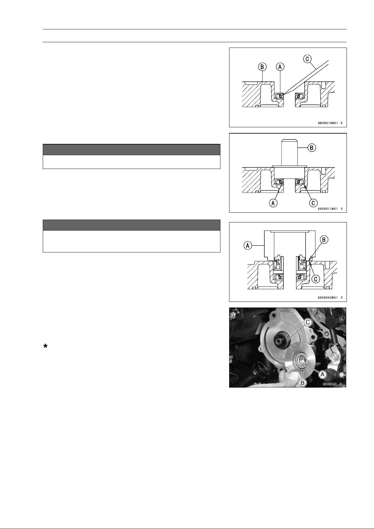
COOLING SYSTEM 4-13
Water Pump
•
Take the oil seal [A] out of the housing [B] with a hook [C].
WaterPumpHousingAssembly
NOTICE
Do not reuse the mechanical seal and oil seal.
•
Apply high-temperature grease to the oil seal lips [A].
•
Press the new oil seal into the housing with a bearing
driver [B] until it stops at the bottom surface [C] of the
housing.
Special Tool - Bearing Driver Set: 57001-1129
NOTICE
Be careful not to damage the sealing surface of the
mechanical seal.
•
Press the new mechanical seal into the housing with the
oil seal driver [A] until its flange [B] touches the surface
[C] of the housing.
Special Tool - Oil Seal Driver: 57001-1660
Mechanical Seal Inspection
•
Remove the water pump impeller (see Water Pump Re-
moval).
•
Visually inspect the mechanical seal.
If any one of the parts is damaged, replace the mechani-
cal seal as a unit.
Impeller Sealing Seat Surface [A]
Rubber Seal [B]
Mechanical Seal [C]
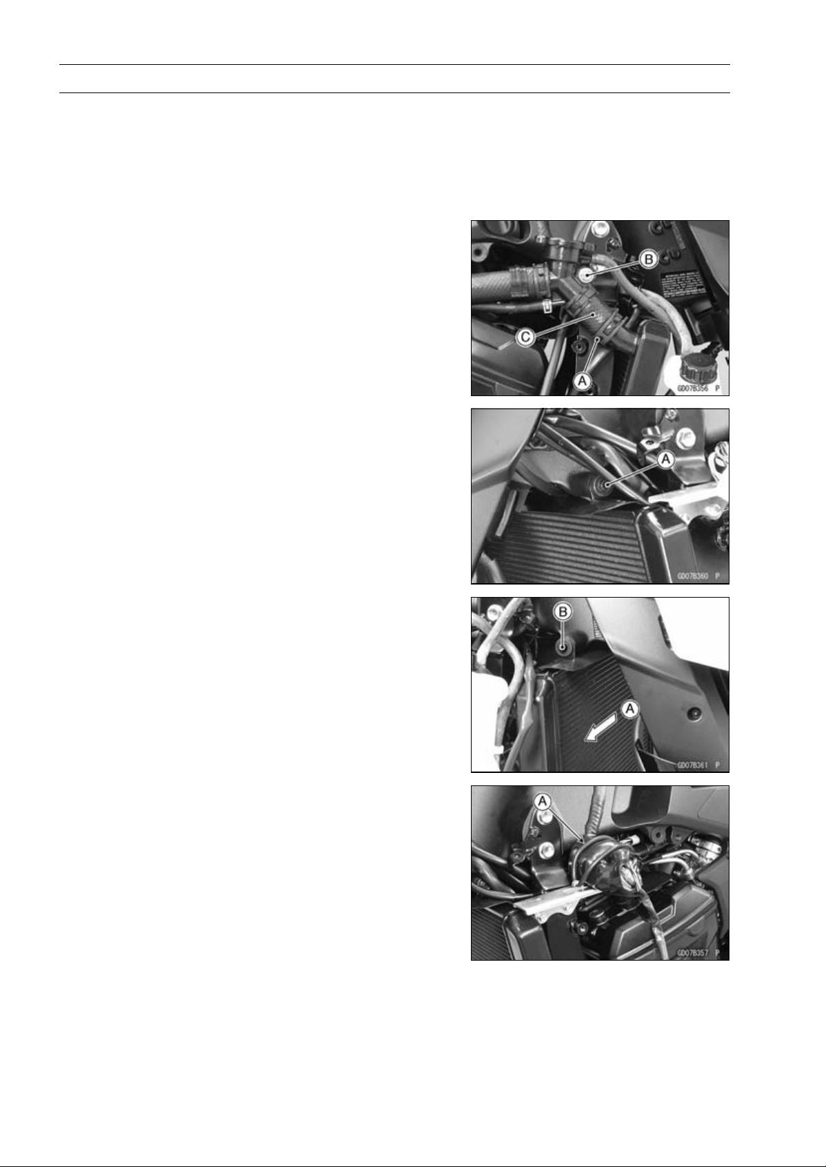
4-14 COOLING SYSTEM
Radiator
Radiator and Radiator Fan Removal
•
Remove:
Center Fairings (see Center Fairing Removal in the
Frame chapter)
Coolant (Drain, see Coolant Change in the Periodic
Maintenance chapter)
•
Remove:
Radiator Hose Clamp [A]
Radiator Cap Mounting Bolt [B]
Radiator Hose [C]
•
Remove:
Radiator Upper Bolt [A]
•
Move the radiator right ward [A] to clear the frame projec-
tion [B].
•
Remove:
Rubber Band [A]
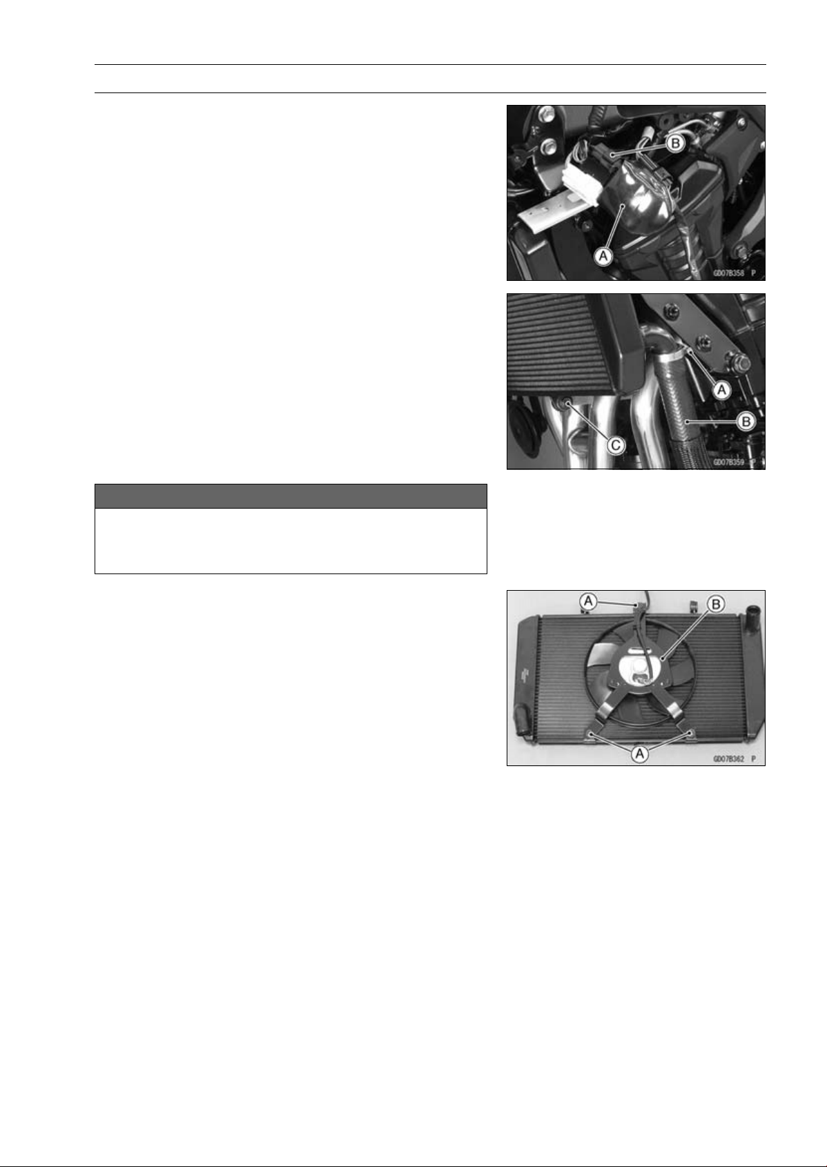
COOLING SYSTEM 4-15
Radiator
•
Slide the connector cover [A] to disconnect the radiator
fan motor lead connector [B].
•
Remove:
Radiator Hose Clamp Screw [A] (Loosen)
Radiator Hose [B]
Radiator Lower Bolt [C]
NOTICE
Do not touch the radiator core. This could damage
the radiator fins, resulting in loss of cooling effi-
ciency.
•
Remove:
Radiator Fan Mounting Bolts [A]
Radiator Fan [B]
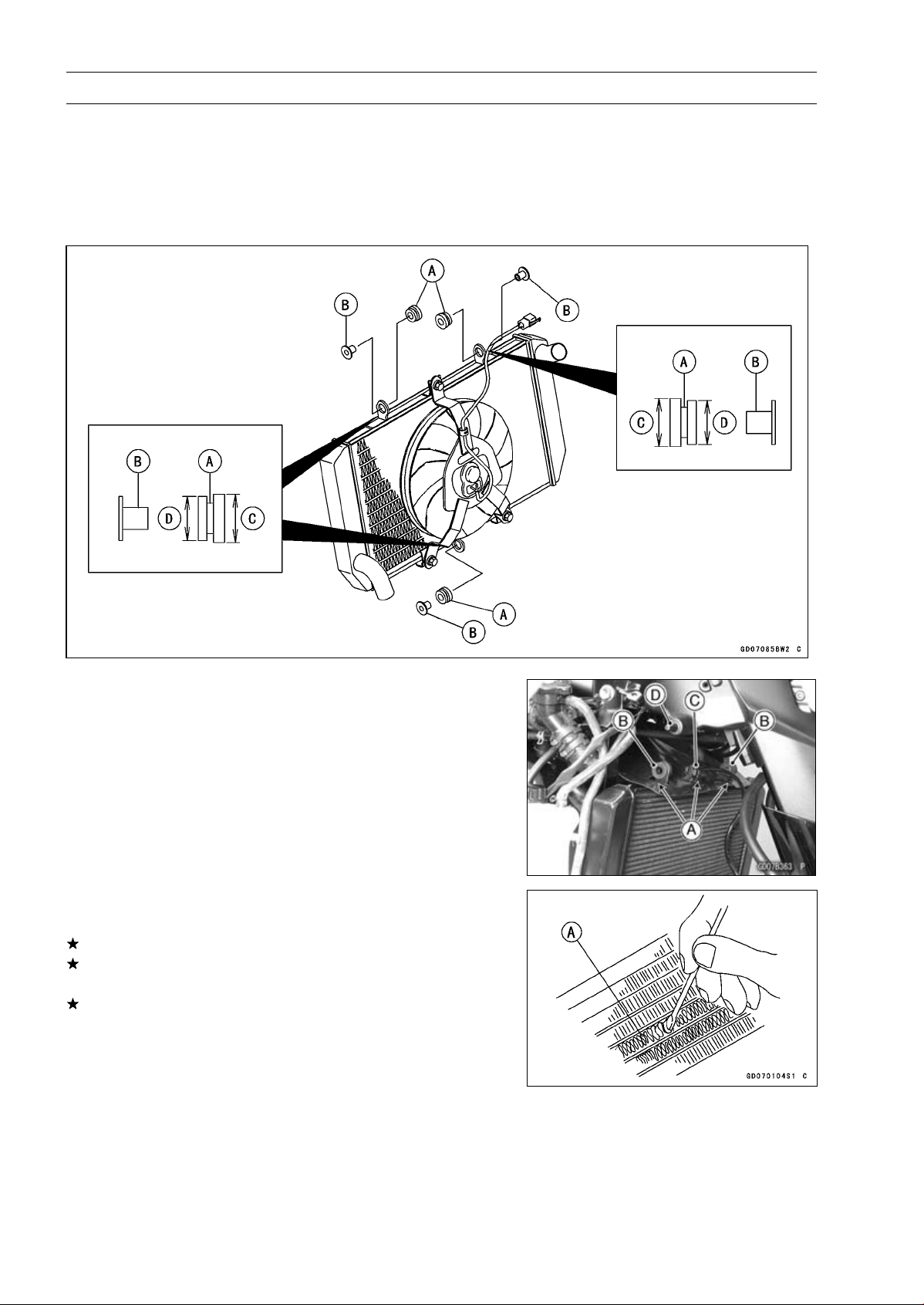
4-16 COOLING SYSTEM
Radiator
Radiator and Radiator Fan Installation
•
Installation is the reverse of removal.
•
Install the rubber dampers [A] and radiator bracket collars
[B] as shown in the figure.
[C] Larger
[D] Smaller
•
Fit the slits [A] of the heat insulation rubber plate to the up-
per mounting brackets [B] and fan bracket [C] as shown.
•
Insert the upper right mounting bracket to the frame pro-
jection [D].
•
Tighten the radiator bolts securely.
•
Connect the radiator fan connector.
•
Install the removed parts (see appropriate chapter).
Radiator Inspection
•
Check the radiator core.
If there are obstructions to air flow, remove them.
If the corrugated fins [A] are deformed, carefully
straighten them.
If the air passages of the radiator core are blocked more
than 20% by unremovable obstructions or irreparably de-
formed fins, replace the radiator with a new one.
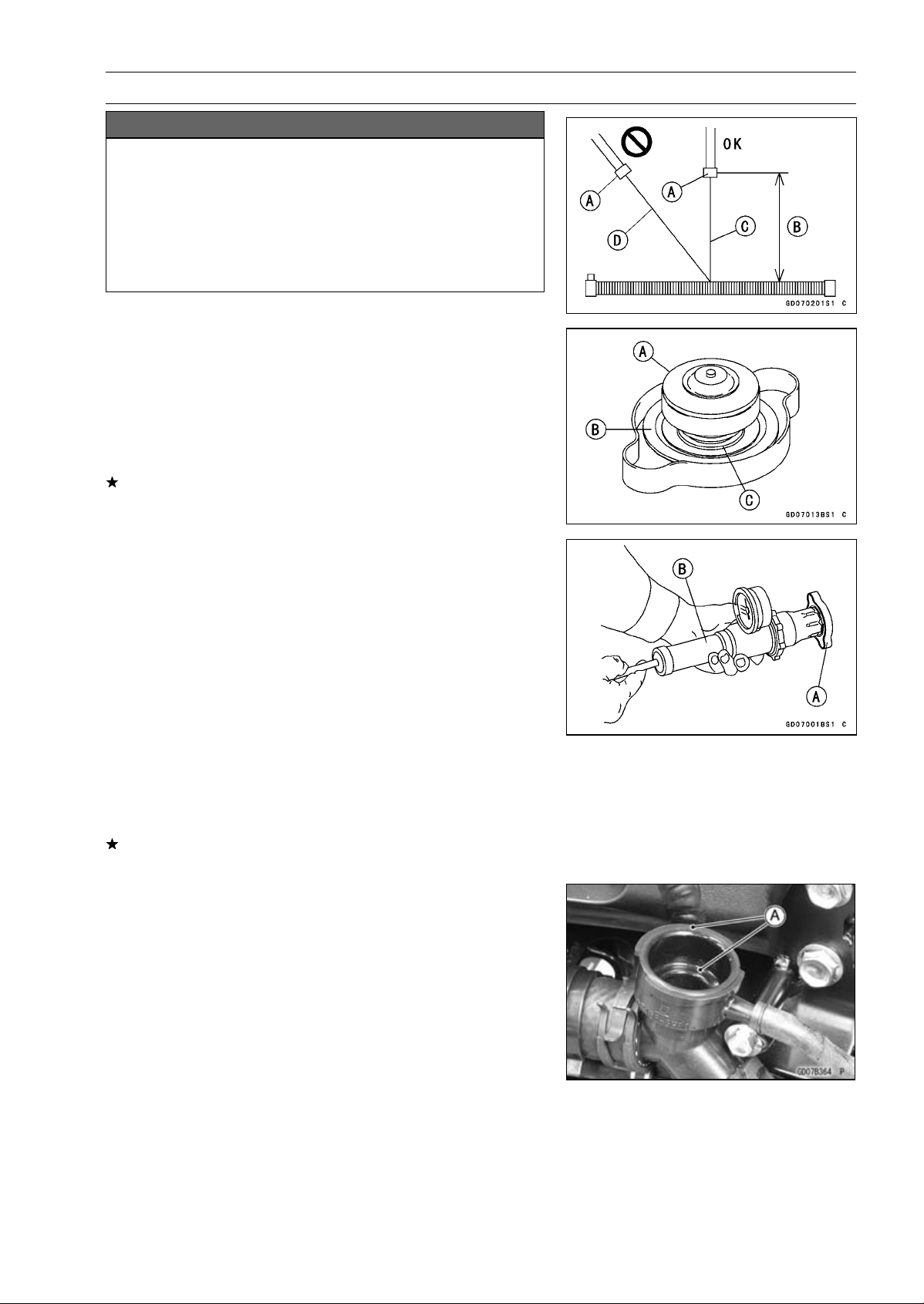
COOLING SYSTEM 4-17
Radiator
NOTICE
When cleaning the radiator with steam cleaner, be
careful of the following to prevent radiator damage:
Keep the steam gun [A] away more than 0.5 m (1.6
ft) [B] from the radiator core.
Hold the steam gun perpendicular [C] (not oblique
[D]) to the core surface.
Run the steam gun, following the core fin direction.
Radiator Cap Inspection
•
Remove:
Right Center Fairing (see Center Fairing Removal in the
Frame chapter)
Radiator Cap
•
Check the condition of the bottom [A] and top [B] valve
seals and valve spring [C].
If any one of them shows visible damage, replace the cap
with a new one.
•
Install the cap [A] on a cooling system pressure tester [B].
NOTE
○
Wet the cap sealing surfaces with water or coolant to
prevent pressure leaks.
•
Watching the pressure gauge, pump the pressure tester
to build up the pressure until the relief valve opens: the
gauge needle flicks downward. Stop pumping and mea-
sure leak time at once. The relief valve must open within
the specified range in the table below and the gauge hand
must remain within the same range at least 6 seconds.
Radiator Cap Relief Pressure
Standard: 93
∼ 123 kPa (0.95 ∼ 1.25 kgf/cm², 13 ∼ 18
psi)
If the cap can not hold the specified pressure or if it holds
too much pressure, replace it with a new one.
Radiator Filler Neck Inspection
•
Remove:
Right Center Fairing (see Center Fairing Removal in the
Frame chapter)
Radiator Cap
•
Check the radiator filler neck for signs of damage.
•
Check the condition of the top and bottom sealing seats
[A] in the filler neck. They must be smooth and clean for
the radiator cap to function properly.
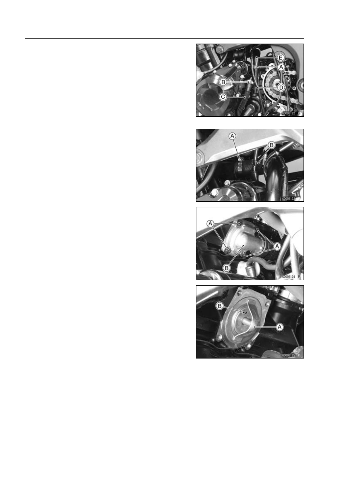
4-18 COOLING SYSTEM
Thermostat
Thermostat Removal
•
Remove:
Coolant (Drain, see Coolant Change in the Periodic
Maintenance chapter)
Engine Sprocket Cover (see Engine Sprocket Removal
in the Final Drive chapter)
Harness Holder Clamp [A]
Water Hose Clamp [B]
Water Hose [C]
Water Pipe Bolts [D]
Water Pipe [E]
•
Loosen the water hose clamp screw [A].
•
Clear the starter motor cable from the holder [B].
•
Remove:
Thermostat Housing Bolts [A]
Thermostat Housing Cover [B]
Thermostat
Thermostat Installation
•
Install the thermostat [A] in the housing so that the air
bleeder hole [B] is on top.
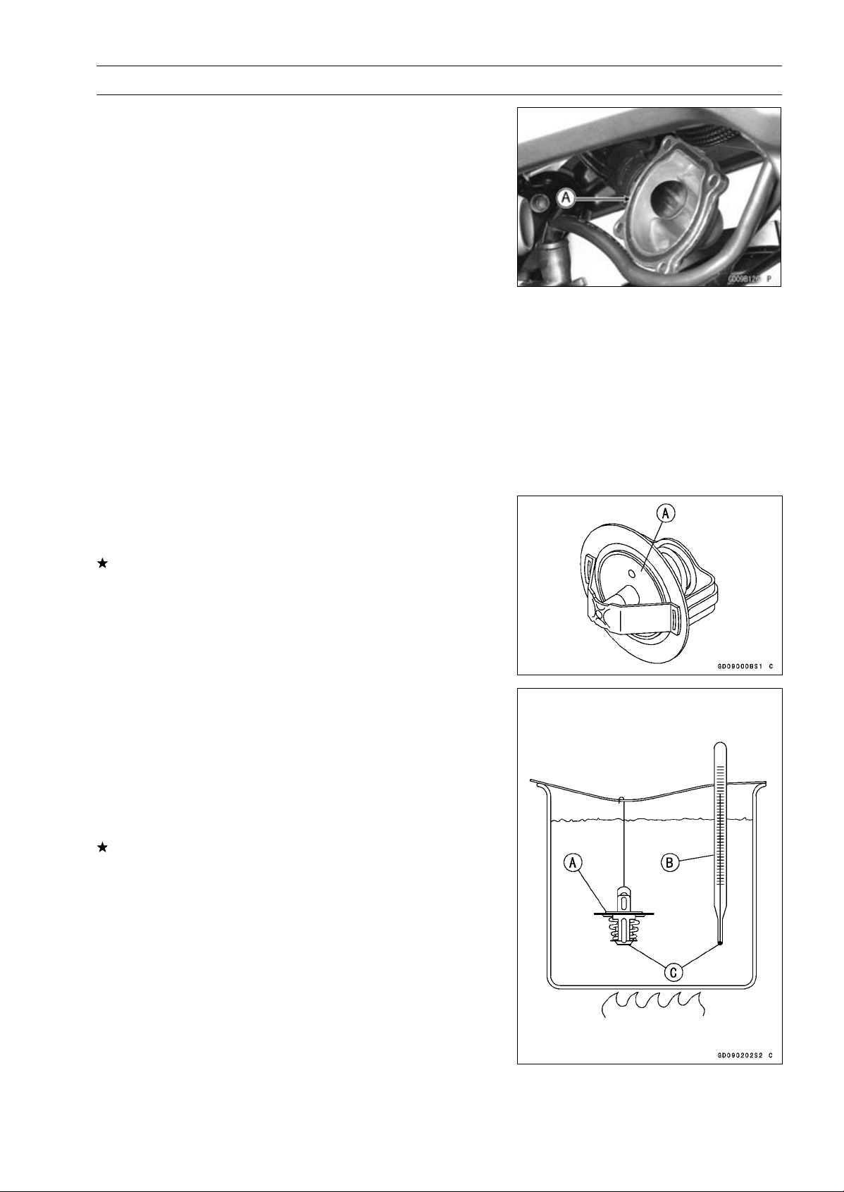
COOLING SYSTEM 4-19
Thermostat
•
Replace the O-ring [A] with a new one.
•
Apply grease to the O-ring, and install it.
•
Install the thermostat housing cover.
NOTE
○
Note that the thermostat does not move at the place
when installing the thermostat housing cover.
•
Tighten:
Torque - Thermostat Housing Bolts: 5.9 N·m (0.60 kgf·m,
52 in·lb)
•
Apply a non-parmanent locking agent to the threads of
the water pipe bolt.
•
Tighten:
Torque - Water Pipe Bolt: 12 N·m (1.2 kgf·m, 106 in·lb)
Radiator (Water) Hose Clamp Screws: 2.9 N·m
(0.30 kgf·m, 26 in·lb)
•
Run the hoses correctly (see Cable, Wire, and Hose Rout-
ing section in the Appendix chapter).
•
Fill the radiator with coolant (see Coolant Change in the
Periodic Maintenance chapter).
Thermostat Inspection
•
Remove the thermostat (see Thermostat Removal), and
inspect the thermostat valve [A] at room temperature.
If the valve is open, replace the thermostat with a new
one.
•
To check valve opening temperature, suspend the ther-
mostat [A] in a container of water and raise the tempera-
ture of the water.
○
The thermostat must be completely submerged and must
not touch the container sides or bottom. Suspend an ac-
curate thermometer [B] in the water so that the heat sen-
sitive portions [C] are located in almost the same depth.
It must not touch the container, either.
If the measurement is out of the specified range, replace
the thermostat with a new one.
Thermostat Valve Opening Temperature
58
∼ 62°C (136 ∼ 144°F)
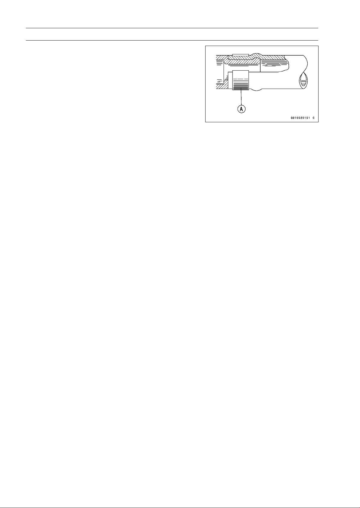
4-20 COOLING SYSTEM
Hose and Pipes
Hose Installation
•
Install the hoses and pipes, being careful to follow bend-
ing direction. Avoid sharp bending, kinking, flattening or
twisting.
•
Run the hoses (see Cable, Wire, and Hose Routing sec-
tion in the Appendix chapter).
•
Install the clamp [A] as near as possible to the hose end
to clear the raised rib of the fitting. This will prevent the
hoses from working loose.
○
The clamp screws should be positioned correctly to pre-
vent the clamps from contacting the other parts.
Torque - Radiator (Water) Hose Clamp Screws: 2.9 N·m
(0.30 kgf·m, 26 in·lb)
Hose Inspection
•
Refer to the Radiator Hose Damage and Installation Con-
dition Inspection in the Periodic Maintenance chapter.

COOLING SYSTEM 4-21
Water Temperature Sensor
NOTICE
The water temperature sensor should never be al-
lowed to fall on a hard surface. Such a shock to the
water temperature sensor can damage it.
Water Temperature Sensor Removal/Installation
•
Refer to the Water Temperature Sensor Removal/Instal-
lation in the Fuel System (DFI) chapter.
Water Temperature Sensor Inspection
•
Refer to the Water Temperature Sensor Inspection in the
Electrical System chapter.


ENGINE TOP END 5-1
5
Engine Top End
Table of Contents
Exploded View................................... 5-2
Exhaust System Identification ........... 5-6
Specifications .................................... 5-9
Special Tools and Sealant ................. 5-11
Clean Air System............................... 5-13
Air Suction Valve Removal........... 5-13
Air Suction Valve Installation........ 5-13
Air Suction Valve Inspection ........ 5-14
Air Switching Valve Removal ....... 5-14
Air Switching Valve Installation .... 5-15
Air Switching Valve Operation
Test............................................ 5-15
Air Switching Valve Unit Test ....... 5-15
Clean Air System Hose
Inspection.................................. 5-15
Cylinder Head Cover ......................... 5-16
Cylinder Head Cover Removal .... 5-16
Cylinder Head Cover Installation . 5-16
Camshaft Chain Tensioner ................ 5-18
Camshaft Chain Tensioner
Removal .................................... 5-18
Camshaft Chain Tensioner
Installation................................. 5-18
Camshaft, Camshaft Chain ............... 5-19
Camshaft Removal ...................... 5-19
Camshaft Installation ................... 5-20
Camshaft, Camshaft Cap Wear
Inspection.................................. 5-24
Camshaft Runout Inspection........ 5-24
Cam Wear Inspection .................. 5-24
Camshaft Chain Removal............ 5-25
Camshaft Chain Installation......... 5-25
Cylinder Head.................................... 5-26
Cylinder Compression
Measurement ............................ 5-26
Cylinder Head Removal............... 5-27
Cylinder Head Installation............ 5-27
Cylinder Head Warp Inspection ... 5-29
Valves ................................................ 5-30
Valve Clearance Inspection ......... 5-30
Valve Clearance Adjustment........ 5-30
Valve Removal ............................. 5-30
Valve Installation .......................... 5-30
Valve Guide Removal .................. 5-30
Valve Guide Installation ............... 5-31
Valve-to-Guide Clearance
Measurement (Wobble
Method)..................................... 5-31
Valve Seat Inspection .................. 5-32
Valve Seat Repair ........................ 5-32
Cylinder, Pistons................................ 5-37
Cylinder Removal......................... 5-37
Cylinder Installation...................... 5-37
Piston Removal............................ 5-38
Piston Installation......................... 5-39
Cylinder Wear Inspection............. 5-39
Piston Wear Inspection ................ 5-40
Piston Ring, Piston Ring Groove
Wear Inspection ........................ 5-40
Piston Ring Groove Width
Inspection.................................. 5-40
Piston Ring Thickness Inspection 5-41
Piston Ring End Gap Inspection.. 5-41
Throttle Body Assy Holder................. 5-42
Throttle Body Assy Holder
Removal .................................... 5-42
Throttle Body Assy Holder
Installation................................. 5-42
Muffler................................................ 5-43
Muffler Body Removal.................. 5-43
Muffler Body Installation............... 5-44
Exhaust Pipe Removal................. 5-46
Exhaust Pipe Installation.............. 5-46
Exhaust Butterfly Valve Cable
Removal .................................... 5-46
Exhaust Butterfly Valve Cable
Installation................................. 5-47
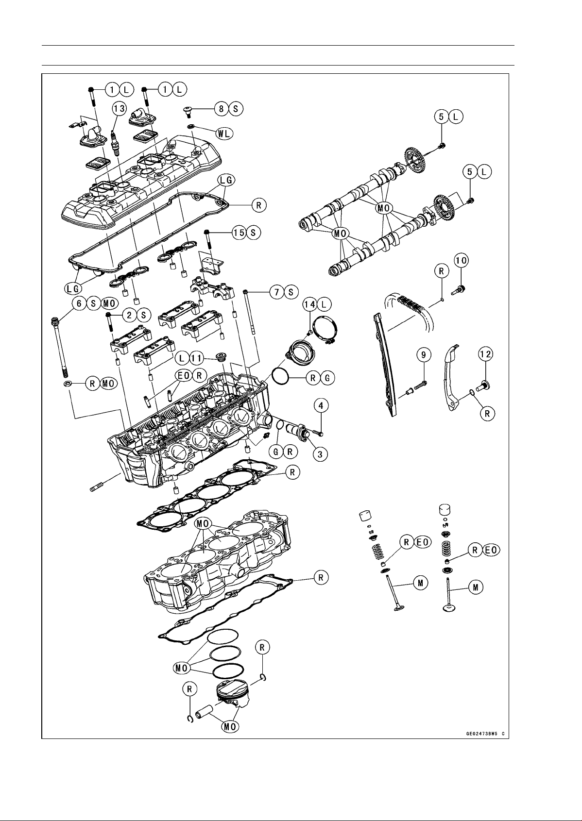
5-2 ENGINE TOP END
Exploded View
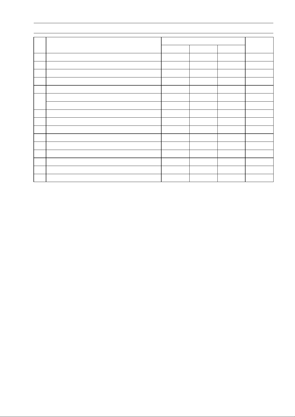
ENGINE TOP END 5-3
Exploded View
Torque
No. Fastener
N·m kgf·m ft·lb
Remarks
1 Air Suction Valve Cover Bolts 9.8 1.0 87 in·lb L
2 Camshaft Cap Bolts 12 1.2 106 in·lb S
3
Camshaft Chain Tensioner Cap Bolt
20 2.0 15
4 Camshaft Chain Tensioner Mounting Bolts 11 1.1 97 in·lb
5 Camshaft Sprocket Bolts 15 1.5 11 L
Cylinder Head Bolts (M10) (First) 20 2.0 15 S, MO
6
Cylinder Head Bolts (M10) (Final) 54 5.5 40 S, MO
7 Cylinder Head Bolts (M6) 12 1.2 106 in·lb S
8
Cylinder Head Cover Bolts
9.8 1.0 87 in·lb
S
9 Front Camshaft Chain Guide Bolt (Lower) 12 1.2 106 in·lb
10 Front Camshaft Chain Guide Bolt (Upper) 25 2.5 18
11 Plugs 19.6 2.0 14 L
12 Rear Camshaft Chain Guide Bolt 25 2.5 18
13 Spark Plugs 13 1.3 115 in·lb
14 Throttle Body Assy Holder Bolts 12 1.2 106 in·lb L
15 Upper Camshaft Chain Guide Bolts 12 1.2 106 in·lb S
EO: Apply engine oil.
G: Apply grease.
L: Apply a non-permanent locking agent.
LG: Apply liquid gasket.
M: Apply molybdenum disulfide grease.
MO: Apply molybdenum disulfide oil solution.
(mixture of the engine oil and molybdenum disulfide grease in a weight ratio 10 : 1)
R: Replacement Parts
S: Follow the specified tightening sequence.
WL: Apply soap and water solution or rubber lubricant.
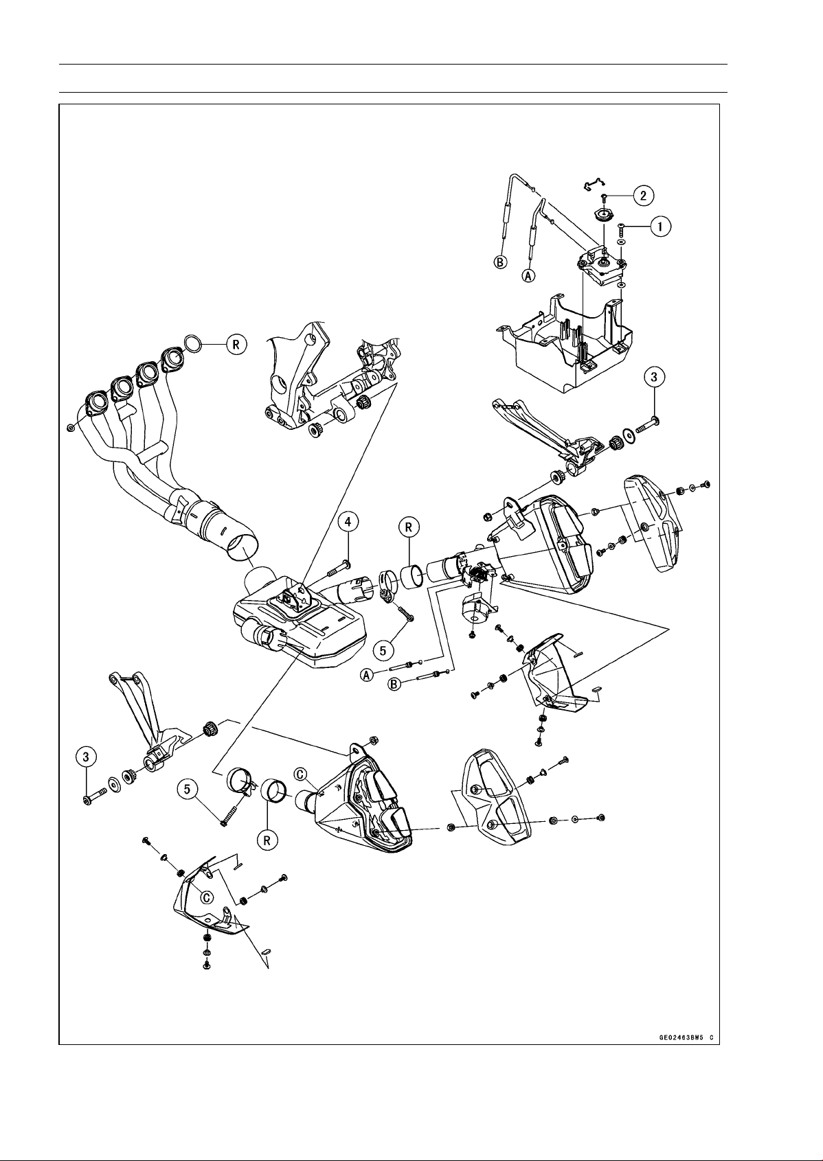
5-4 ENGINE TOP END
Exploded View

ENGINE TOP END 5-5
Exploded View
Torque
No. Fastener
N·m kgf·m ft·lb
Remarks
1 Exhaust Butterfly Valve Actuator Bolts 4.3 0.44 38 in·lb
2 Exhaust Butterfly Valve Actuator Pulley Bolt 5.0 0.51 44 in·lb
3
Muffler Body Mounting Bolts
34 3.5 25
4 Premuffler Chamber Mounting Bolt 34 3.5 25
5 Muffler Body Clamp Bolts 21 2.1 15
R: Replacement Parts
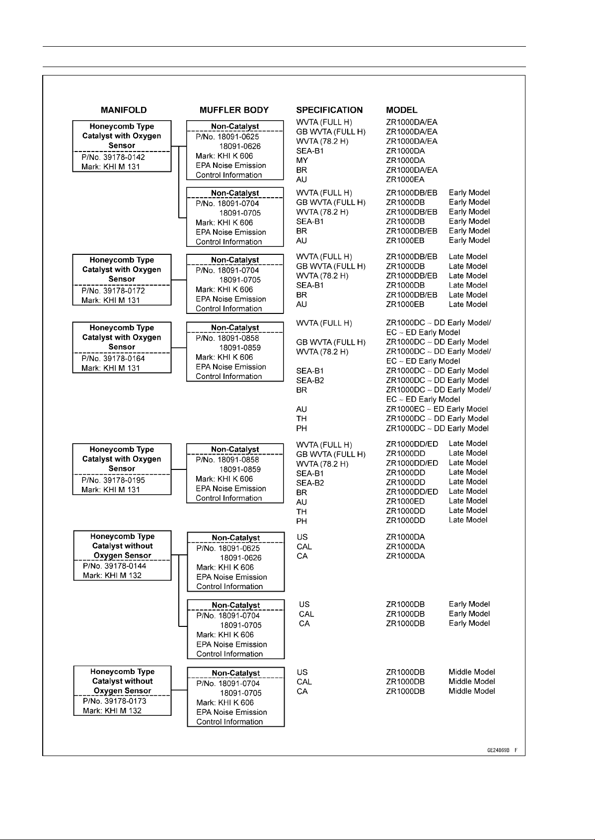
5-6 ENGINE TOP END
Exhaust System Identification
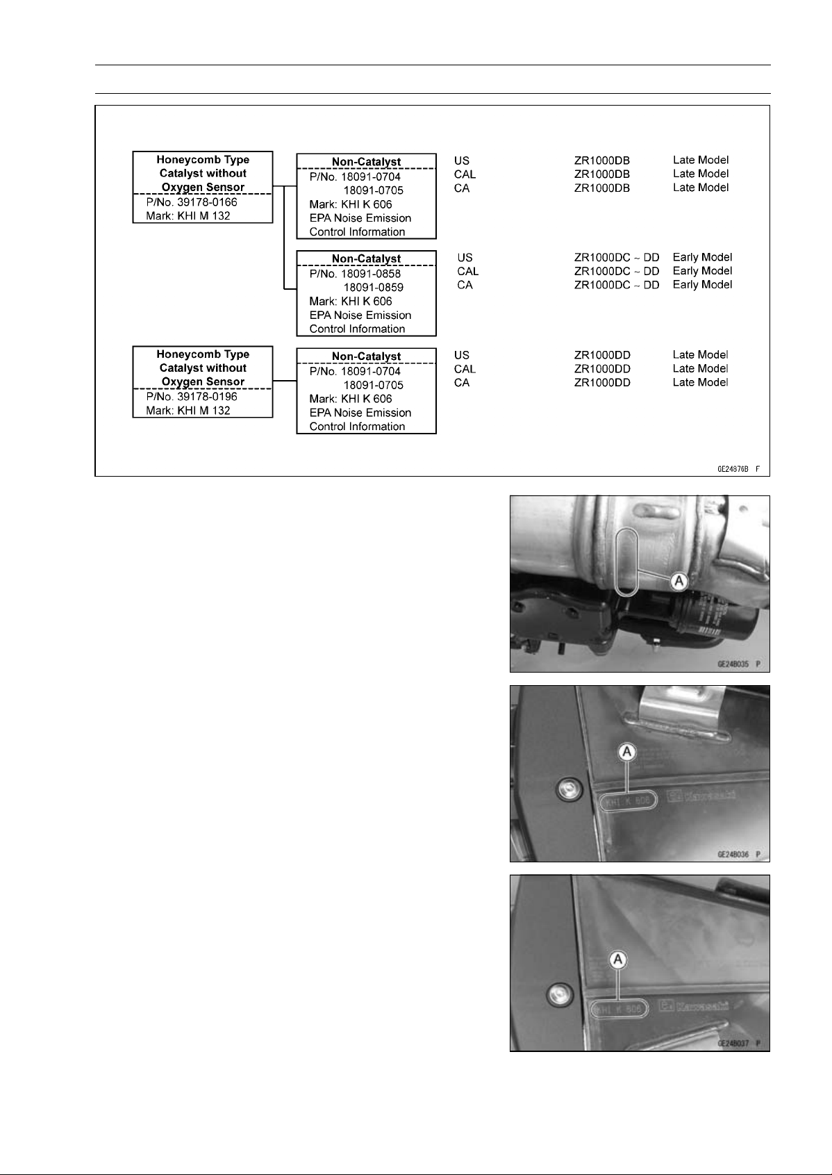
ENGINE TOP END 5-7
Exhaust System Identification
Exhaust Pipe Mark Position [A]
Left Muffler Body Mark Position [A]
Right Muffler Body Mark Position [A]
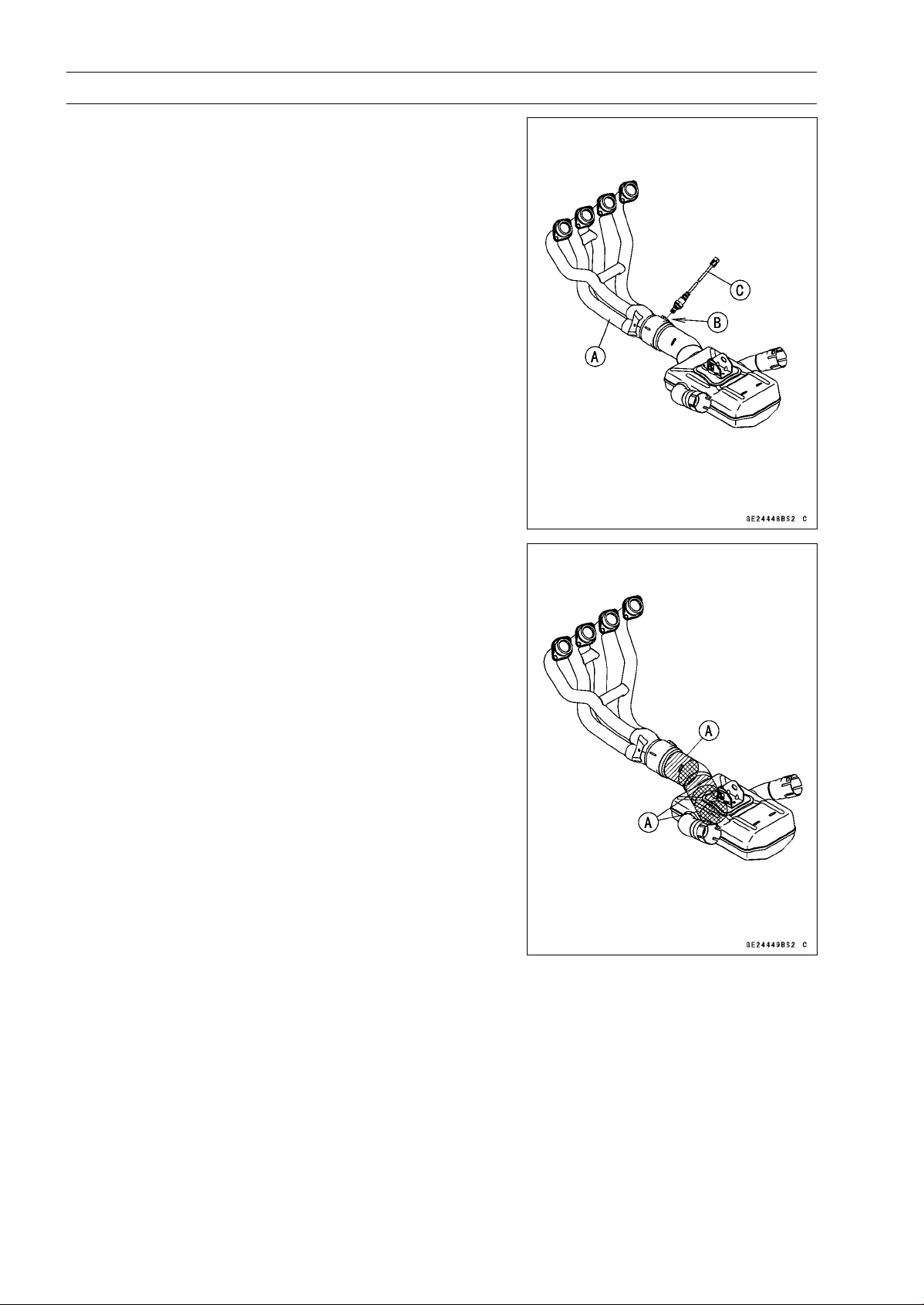
5-8 ENGINE TOP END
Exhaust System Identification
Exhaust Pipe [A] with Hole [B] for Oxygen Sensor [C]
(Equipped Models)
Honeycomb Type Catalyst Positions [A]

ENGINE TOP END 5-9
Specifications
Item Standard Service Limit
Camshafts
Cam Height:
Exhaust
33.743 ∼ 33.857 mm (1.3285 ∼ 1.3330 in.) 33.64 mm (1.324 in.)
Intake
34.743 ∼ 34.857 mm (1.3678 ∼ 1.3723 in.) 34.64 mm (1.364 in.)
Camshaft Journal, Camshaft
Cap Clearance
0.038 ∼ 0.081 mm (0.0015 ∼ 0.0032 in.) 0.17 mm (0.0067 in.)
Camshaft Journal Diameter 23.940 ∼ 23.962 mm (0.9425 ∼ 0.9434 in.) 23.91 mm (0.9413 in.)
Camshaft Bearing Inside
Diameter
24.000 ∼ 24.021 mm (0.9449 ∼ 0.9457 in.) 24.08 mm (0.9480 in.)
Camshaft Runout TIR 0.02 mm (0.0008 in.) or less TIR 0.1 mm (0.004 in.)
Cylinder Head
Cylinder Compression (Usable Range)
966 ∼ 1 478 kPa (9.9 ∼ 15.1 kgf/cm², 140 ∼
214 psi) at 280 r/min (rpm)
–––
Cylinder Head Warp
–––
0.05 mm (0.002 in.)
Valves
Valve Clearance:
Exhaust 0.22 ∼ 0.31 mm (0.0087 ∼ 0.0122 in.) –––
Intake 0.15 ∼ 0.24 mm (0.0059 ∼ 0.0094 in.) –––
Valve Head Thickness:
Exhaust 0.8 mm (0.031 in.) 0.6 mm (0.024 in.)
Intake 0.5 mm (0.020 in.) 0.3 mm (0.012 in.)
Valve Stem Bend TIR 0.01 mm (0.0004 in.) or less TIR 0.05 mm (0.002 in.)
Valve Stem Diameter:
Exhaust 4.455 ∼ 4.470 mm (0.1754 ∼ 0.1760 in.) 4.44 mm (0.175 in.)
Intake
4.475 ∼ 4.490 mm (0.1762 ∼ 0.1768 in.) 4.46 mm (0.176 in.)
Valve Guide Inside Diameter:
Exhaust
4.500 ∼ 4.512 mm (0.1772 ∼ 0.1776 in.) 4.58 mm (0.180 in.)
Intake 4.500 ∼ 4.512 mm (0.1772 ∼ 0.1776 in.) 4.58 mm (0.180 in.)
Valve/Valve Guide
Clearance (Wobble Method):
Exhaust 0.08 ∼ 0.14 mm (0.0031 ∼ 0.0055 in.) 0.31 mm (0.012 in.)
Intake 0.03 ∼ 0.10 mm (0.0012 ∼ 0.0039 in.) 0.29 mm (0.011 in.)
Valve Seat Cutting Angle 32°, 45°, 60°
–––
Valve Seating Surface:
Width:
Exhaust 0.8 ∼ 1.2 mm (0.031 ∼ 0.047 in.) –––
Intake 0.5 ∼ 1.0 mm (0.020 ∼ 0.039 in.) –––
Outside Diameter:
Exhaust 24.7 ∼ 24.9 mm (0.972 ∼ 0.980 in.) –––
Intake
28.9 ∼ 29.1 mm (1.138 ∼ 1.146 in.)
–––
Valve Spring Free Length:
Exhaust
36.62 mm (1.442 in.) 35.2 mm (1.39 in.)
Intake 36.62 mm (1.442 in.) 35.2 mm (1.39 in.)
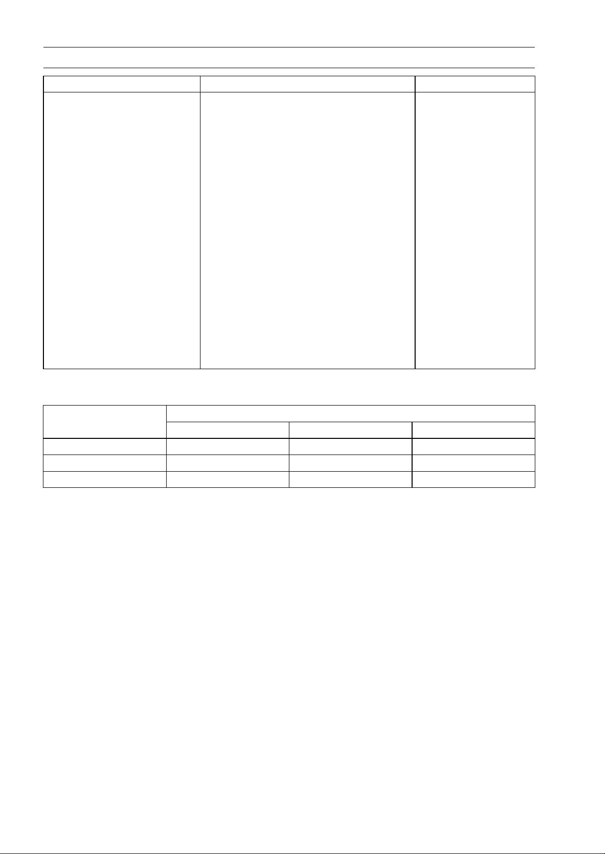
5-10 ENGINE TOP END
Specifications
Item Standard Service Limit
Cylinder, Pistons
Cylinder Inside Diameter 76.994 ∼ 77.006 mm (3.0313 ∼ 3.0317 in.) 77.09 mm (3.035 in.)
Piston Diameter 76.974 ∼ 76.984 mm (3.0305 ∼ 3.0309 in.) 76.82 mm (3.024 in.)
Piston/Cylinder Clearance 0.010 ∼ 0.032 mm (0.0004 ∼ 0.0013 in.) –––
Piston Ring/Groove
Clearance:
Top
0.03 ∼ 0.07 mm (0.0012 ∼ 0.0028 in.) 0.17 mm (0.0067 in.)
Second 0.02 ∼ 0.06 mm (0.000
8 ∼ 0.0024 in.)
0.16 mm (0.0063 in.)
Piston Ring Groove Width:
Top 0.82 ∼ 0.84 mm (0.0323 ∼ 0.0331 in.) 0.92 mm (0.0362 in.)
Second 0.81 ∼ 0.83 mm (0.0319 ∼ 0.0327 in.) 0.91 mm (0.0358 in.)
Piston Ring Thickness:
Top
0.77 ∼ 0.79 mm (0.0303 ∼ 0.0311 in.) 0.70 mm (0.028 in.)
Second 0.77 ∼ 0.79 mm (0.0
303 ∼ 0.0311 in.)
0.70 mm (0.028 in.
)
Piston Ring End Gap:
Top 0.20 ∼ 0.30 mm (0.0079 ∼ 0.0118 in.) 0.6 mm (0.024 in.)
Second 0.38 ∼ 0.48 mm (0.0150 ∼ 0.0189 in.) 0.8 mm (0.031 in.)
Crankshaft, Camshaft Chain, Camshaft Sprocket Selection
Part Number
Engine Number/Model
Crankshaft Camshaft Chain Camshaft Sprocket
∼ ZRT00DE016592 13031-0125 92057-1453 12046-0083
ZRT0
0DE016593 ∼
1303
1-0710
9205
7-0202
1204
6-0563
ZR1000DD/ED
13031-0710 92057-0202 12046-0564
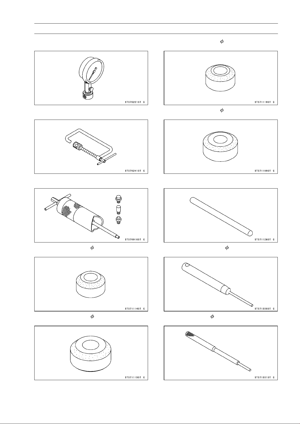
ENGINE TOP END 5-11
Special Tools and Sealant
Compression Gauge, 20 kgf/cm²:
57001-221
Valve Spring Compressor Assembly:
57001-241
Piston Pin Puller Assembly:
57001-910
Valve Seat Cutter, 45° - 27.5:
57001-1114
Valve Seat Cutter, 45° - 32:
57001-1115
Valve Seat Cutter, 32° - 28:
57001-1119
Valve Seat Cutter, 32° - 33:
57001-1199
Valve Seat Cutter Holder Bar:
57001-1128
Valve Seat Cutter Holder, 4.5:
57001-1330
Valve Guide Arbor, 4.5:
57001-1331
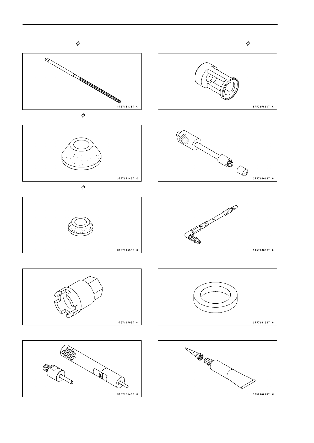
5-12 ENGINE TOP END
Special Tools and Sealant
Valve Guide Reamer, 4.5:
57001-1333
Valve Seat Cutter, 60° - 33:
57001-1334
Valve Seat Cutter, 60° - 27:
57001-1409
Engine Mount Nut Wrench:
57001-1450
Valve Guide Driver:
57001-1564
Valve Spring Compressor Adapter, 24:
57001-1586
Compression Gauge Adapter, M10 × 1.0:
57001-1601
L-Shape Hose:
57001-1606
Washer:
57001-1612
Liquid Gasket, TB1216B:
92104-1064

ENGINE TOP END 5-13
Clean Air System
Air Suction Valve Removal
•
Remove:
Left Center Fairing (see Center Fairing Removal in the
Frame chapter)
Air Switching Valve (see Air Switching Valve Removal)
Connector [A] (from Bracket [B] at Left Side)
Air Suction Valve Cover Bolts [C] and Bracket
Air Suction Valve Covers [D] (Both Sides)
•
Remove the air suction valves [A] on both sides.
Air Suction Valve Installation
•
Install the air suction valve so that opening [A] of the reed
faces the front and downward.
•
Install the bracket [A] as shown in the figure.
•
Apply a non-permanent locking agent to the threads of
the air suction valve cover bolts [B], and tighten them.
Torque - Air Suction Valve Cover Bolts: 9.8 N·m (1.0 kgf·m,
87 in·lb)
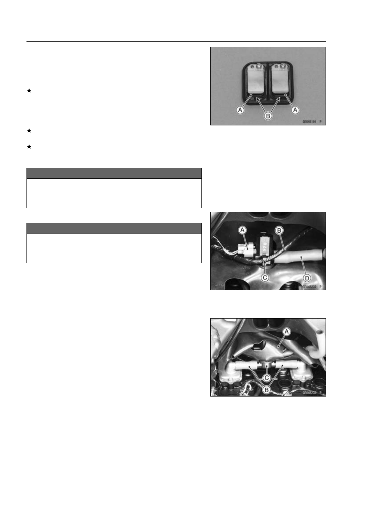
5-14 ENGINE TOP END
Clean Air System
Air Suction Valve Inspection
•
Remove the air suction valve (see Air Suction Valve Re-
moval).
•
Visually inspect the reeds [A] for cracks, folds, warps,
heat damage or other damage.
If there is any doubt as to the condition of the reeds, re-
place the air suction valve as an assembly.
•
Check the reed contact areas [B] of the valve holder for
grooves, scratches, any signs of separation from the
holder or heat damage.
If there is any doubt as to the condition of the reed contact
areas, replace the air suction valve as an assembly.
If any carbon or other foreign particles have accumulated
between the reed and the reed contact area, wash the
valve assembly clean with a high flash-point solvent.
NOTICE
Do not scrape off the deposits with a scraper as this
could damage the rubber, requiring replacement of
the suction valve assembly.
Air Switching Valve Removal
NOTICE
Never drop the air switching valve especially on a
hard surface. Such a shock to the air switching
valve can damaged it.
•
Remove the stick coils (see Stick Coil Removal in the
Electrical System chapter).
•
Disconnect the connector [A].
•
Clear the harness [B] from the clamp [C].
•
For California models, separate the hose [D] from the air
switching valve.
•
Turn over the heat insulation rubber plate [A].
•
Separate the hoses [B] from the air switching valve [C] to
remove the air switching valve.
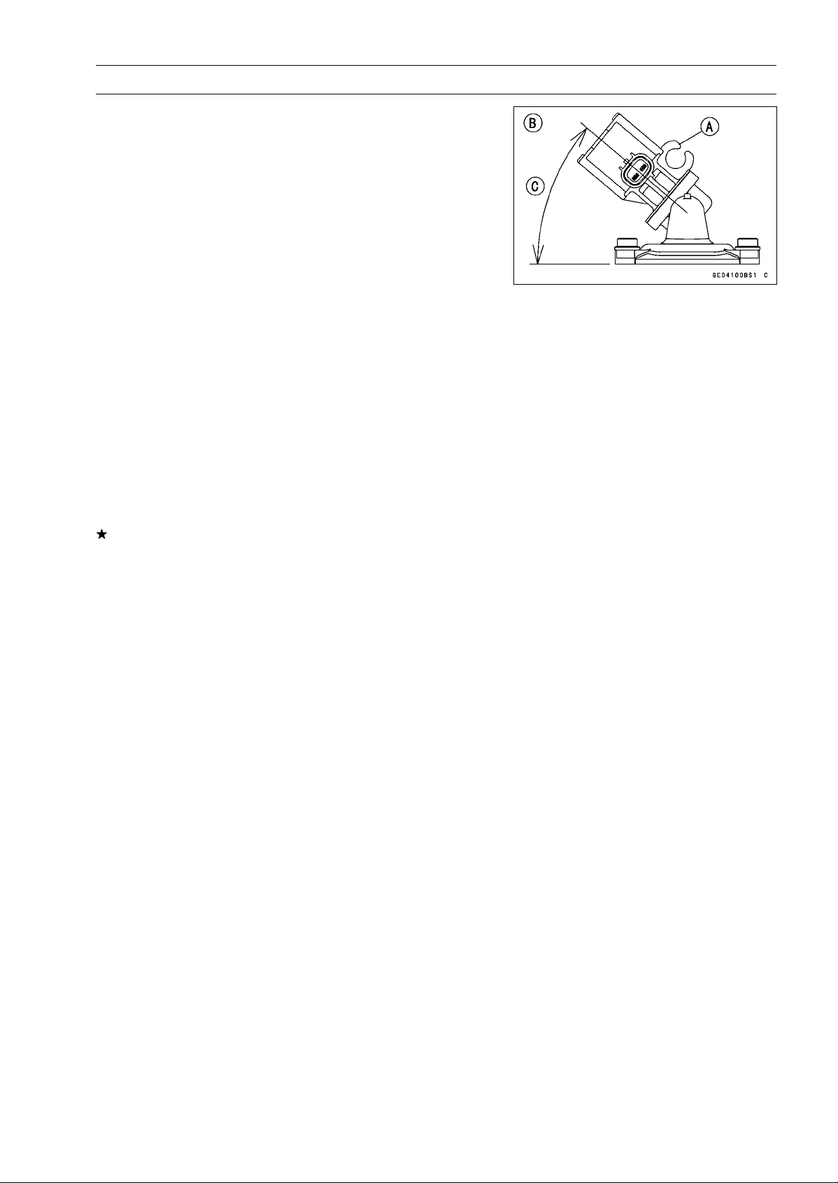
ENGINE TOP END 5-15
Clean Air System
Air Switching Valve Installation
•
Install the air switching valve [A] as shown in the figure.
[B]ViewedLeftSide
[C] About 40°
Air Switching Valve Operation Test
•
Refer to the Air Suction System Damage Inspection in the
Periodic Maintenance chapter.
Air Switching Valve Unit Test
•
Refer to the Air Switching Valve Unit Test in the Electrical
System chapter.
Clean Air System Hose Inspection
•
Be certain that all the hoses are routed without being flat-
tened or kinked, and are connected correctly to the air
cleaner housing, air switching valve and air suction valve
covers.
If they are not, correct them. Replace them if they are
damaged.
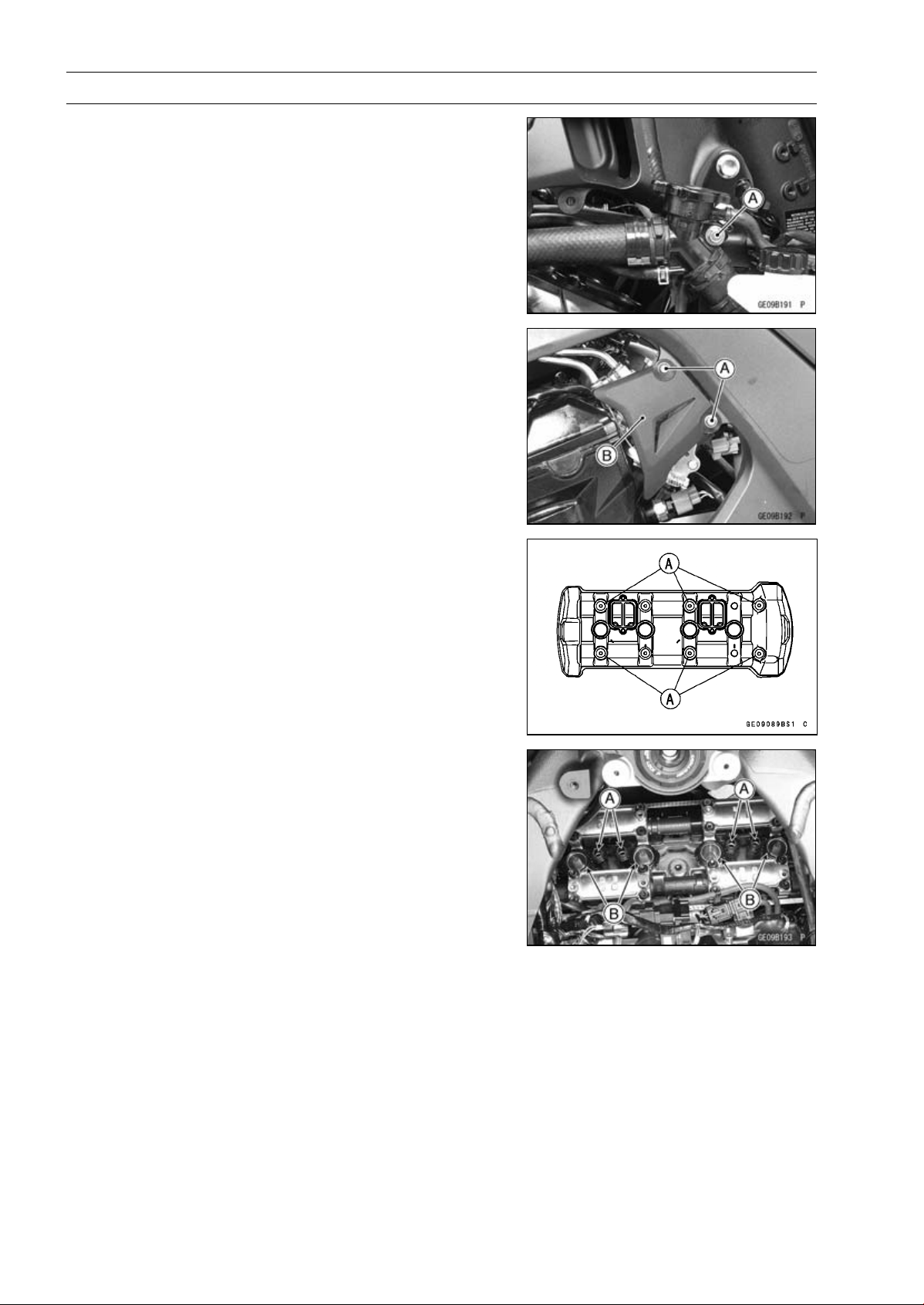
5-16 ENGINE TOP END
Cylinder Head Cover
Cylinder Head Cover Removal
•
Remove:
Right Center Fairing (see Center Fairing Removal in the
Frame chapter)
Radiator Cap Mounting Bolt [A]
•
Remove:
Throttle Pulley Cover Bolts [A]
Throttle Pulley Cover [B]
•
Remove:
Air Suction Valve (see Air Suction Valve Removal)
Cylinder Head Cover Bolts [A]
Cylinder Head Cover
Cylinder Head Cover Installation
•
Install:
Dowel Pins [A]
Plug Hole Gaskets [B]
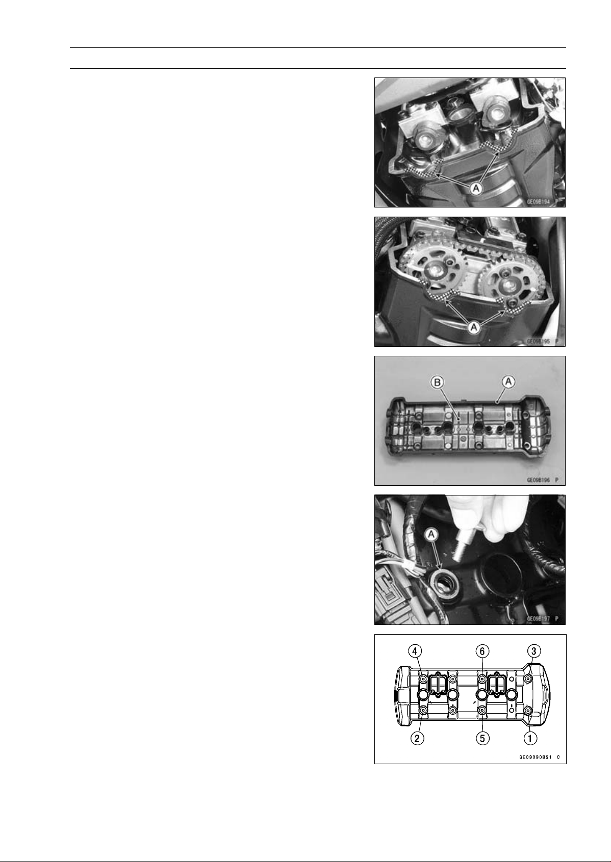
ENGINE TOP END 5-17
Cylinder Head Cover
•
Using a cleaning fluid, clean off any oil or dirt on the cylin-
der head [A] as shown and dry them with a clean cloth.
•
Apply liquid gasket to the cylinder head as shown.
Sealant - Liquid Gasket, TB1216B: 92104-1064
NOTE
○
Make the application finish within 20 minutes when the
liquid gasket to the mating surface of the cylinder head
is applied.
○
Moreover fit the cylinder head and tighten the bolts just
after application of the liquid gasket.
•
Replace the head cover gasket [A] with a new one.
•
Install the gasket to the cylinder head cover [B].
•
While pulling up the water hose on radiator cap, install the
cylinder head cover from the right side.
•
Apply sorp and water solution or rubber lubricant to the
both surface of the washers.
•
Install the washers with the metal side [A] faces upward.
•
Tighten the cover bolts following the specified tightening
sequence.
Torque - Cylinder Head Cover Bolts: 9.8 N·m (1.0 kgf·m, 87
in·lb)
•
Install the removed parts (see appropriate chapters).
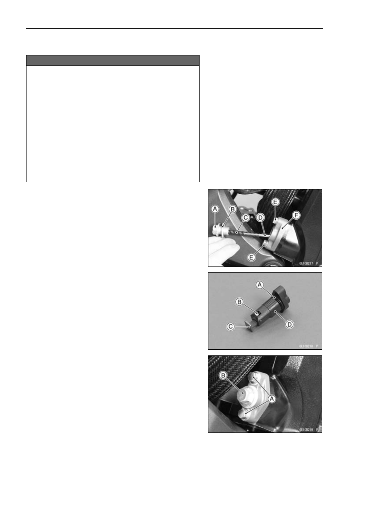
5-18 ENGINE TOP END
Camshaft Chain Tensioner
Camshaft Chain Tensioner Removal
NOTICE
This is a non-return type camshaft chain tensioner.
The push rod does not return to its original position
once it moves out to take up camshaft chain slack.
Observe all the rules listed below.
When removing the tensioner, do not take out the
mounting bolts only halfway. Retightening the
mounting bolts from this position could damage
the tensioner and the camshaft chain. Once the
bolts are loosened, the tensioner must be removed
and reset as described in “Camshaft Chain Ten-
sioner Installation”.
Do not turn over the crankshaft while the tensioner
is removed. This could upset the camshaft chain
timing, and damage the valves.
•
Remove:
Cap Bolt [A]
Washer [B]
Spring [C]
Rod [D]
Mounting Bolts [E]
Camshaft Chain Tensioner [F]
Camshaft Chain Tensioner Installation
•
Replace the O-ring [A] with a new one.
•
Apply grease to the new O-ring.
•
Release the stopper [B] and push the push rod [C] into
the tensioner body [D].
•
Install the tensioner body so that the stopper faces up-
ward.
•
Tighten:
Torque - Camshaft Chain Tensioner Mounting Bolts [A]: 11
N·m (1.1 kgf·m, 97 in·lb)
•
Install the rod, spring and washer.
•
Tighten:
Torque - Camshaft Chain Tensioner Cap Bolt [B]: 20 N·m
(2.0 kgf·m, 15 ft·lb)
•
Turn the crankshaft 2 turns clockwise to allow the ten-
sioner to expand and recheck the camshaft chain timing.
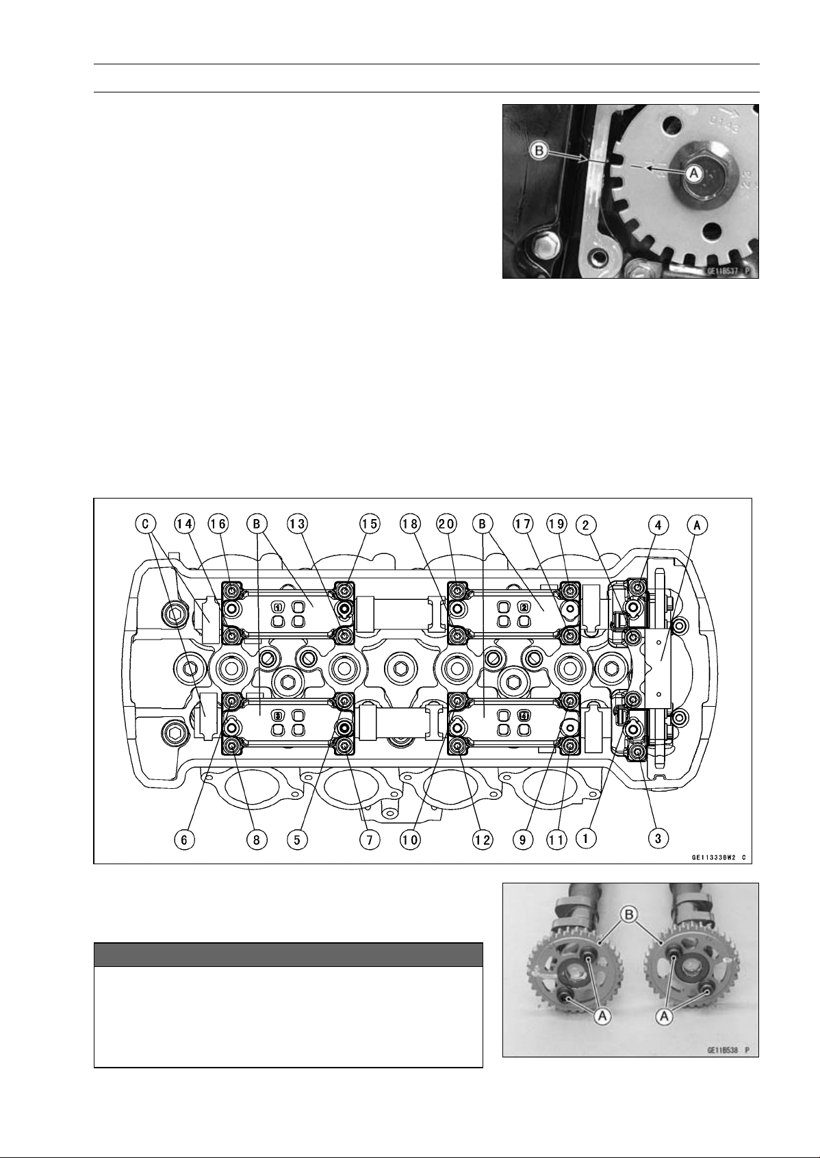
ENGINE TOP END 5-19
Camshaft, Camshaft Chain
Camshaft Removal
•
Remove:
Cylinder Head Cover (see Cylinder Head Cover Re-
moval)
Crankshaft Sensor Cover (see Crankshaft Sensor Re-
moval in the Electrical System chapter)
•
Turn the crankshaft clockwise, align the #1, 4 mark on the
timing rotor with the crankcase timing mark.
TDC mark [A] for #1, 4 Pistons
Timing Mark (Crankcase Halves Mating Surface) [B]
•
Remove the camshaft chain tensioner (see Camshaft
Chain Tensioner Removal).
•
Loosen the upper chain guide bolts and camshaft cap
bolts as shown sequence [1 ∼ 20] in the figure, and re-
move them.
•
Remove:
Upper Chain Guide [A]
Camshaft Caps [B]
Camshafts [C]
•
Stuff a clean cloth into the chain tunnel to keep any parts
from dropping into the crankcase.
•
Remove:
Camshaft Sprocket Mounting Bolts [A]
Camshaft Sprockets [B]
NOTICE
The crankshaft may be turned while the camshafts
are removed. Always pull the chain taut while turn-
ing the crankshaft. This avoids kinking the chain
on the lower (crankshaft) sprocket. A kinked chain
could damage both the chain and the sprocket.
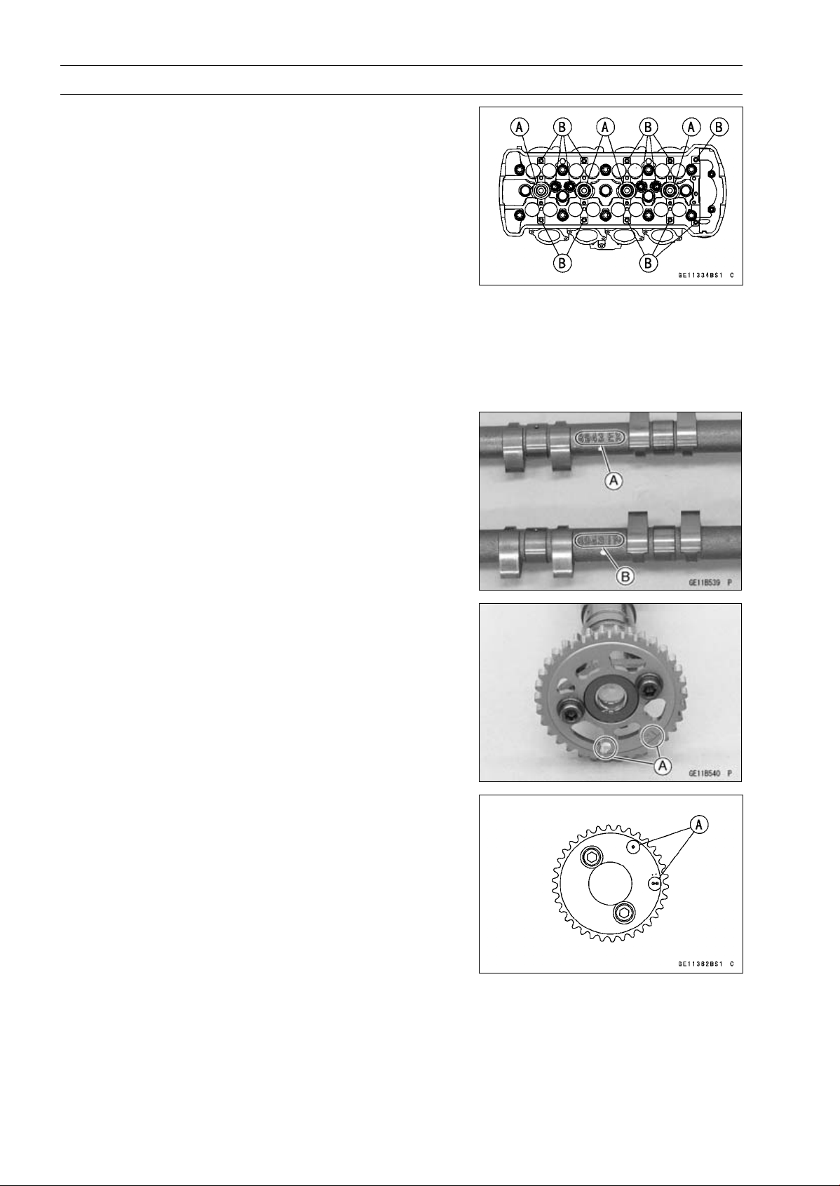
5-20 ENGINE TOP END
Camshaft, Camshaft Chain
Camshaft Installation
NOTE
○
The crankshaft, camshaft chain and camshaft sprock-
ets are different between the early production models
(Engine Number:
∼
ZRT00DE016592), the late produc-
tion models (Engine Number: ZRT00DE016593
∼
) and
ZR1000DD/ED.
○
Do not use these parts in a combination of the ear-
lier production models, later production models and
ZR1000DD/ED (see the table of specification for the
Crankshaft, Camshaft Chain and Camshaft Sprocket
Selection) .
•
Be sure to install the following parts.
Plug Hole Gaskets [A]
Dowel Pins [B]
NOTE
○
The exhaust camshaft has a 8943 EX mark [A] and the
intake camshaft has a 8943 IN mark [B]. Be careful not
to mix up these shafts.
•
Install the camshaft sprockets so that position the timing
marks [A] outside (Engine Number: ∼ ZRT00DE016592
and ZR1000DD/ED) .
•
Install the camshaft sprockets so that position the timing
marks [A] outside (Engine Number:ZRT00DE016593 ∼)
○
The intake camshaft sprocket and exhaust camshaft
sprocket are identical.
•
Apply a non-permanent locking agent to the threads of
the camshaft sprocket bolts and tighten them.
Torque - Camshaft Sprocket Bolts: 15 N·m (1.5 kgf·m, 11
ft·lb)
•
Apply molybdenum disulfide oil solution to all cam parts
and journals.
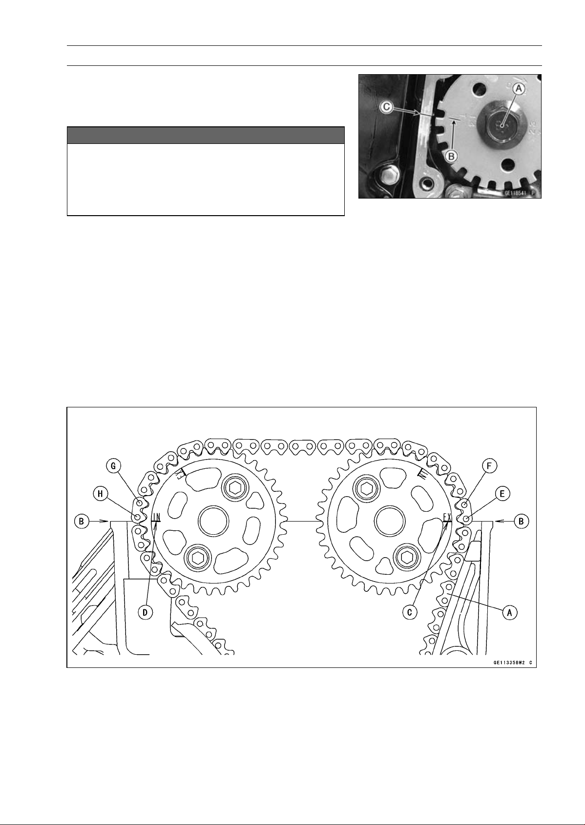
ENGINE TOP END 5-21
Camshaft, Camshaft Chain
•
Using a wrench on the timing rotor bolt [A], turn the crank-
shaft clockwise until the line [B] (TDC mark for #1,4 pis-
tons) on the timing rotor is aligned with the timing mark
[C] (Crankcase Halves Mating Surface).
NOTICE
The crankshaft may be turned while the camshafts
are removed. Always pull the chain taut while turn-
ing the crankshaft. This avoids kinking the chain
on the lower (crankshaft) sprocket. A kinked chain
could damage both the chain and the sprocket.
•
Pull the tension side (exhaust side) [A] of the chain taut
to install the chain.
•
Engage the camshaft chain with the sprockets so that tim-
ing marks on the sprockets are positioned as shown in the
figure.
○
The timing marks must be aligned with the cylinder head
upper surface [B] (Engine Number: ∼ ZRT00DE016592
and ZR1000DD/ED).
EX mark [C]
IN mark [D]
#1 pin [E]
#2 pin [F]
#29 pin [G]
#30 pin [H]
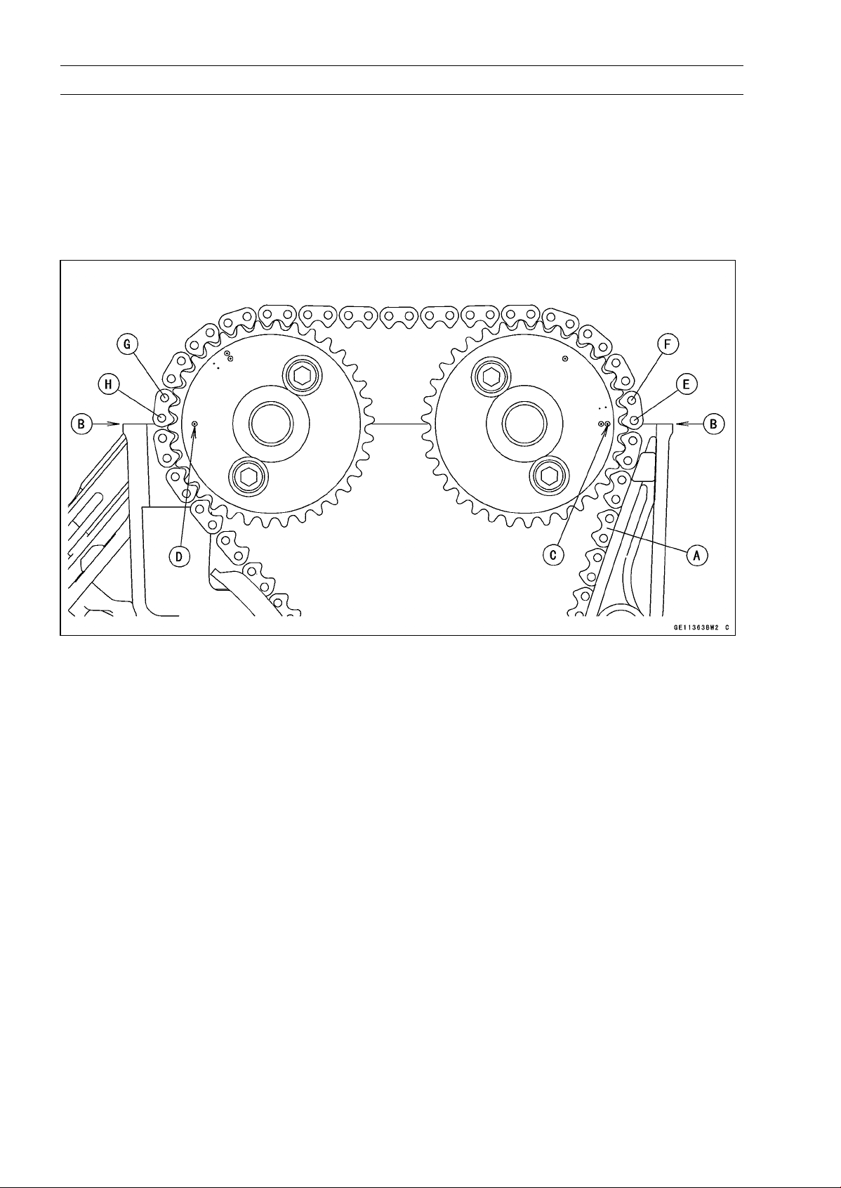
5-22 ENGINE TOP END
Camshaft, Camshaft Chain
○
The timing marks must be aligned with the cylinder head
upper surface [B] (Engine Number: ZRT00DE016593 ∼).
EX mark [C]
IN mark [D]
#1 pin [E]
#2 pin [F]
#29 pin [G]
#30 pin [H]
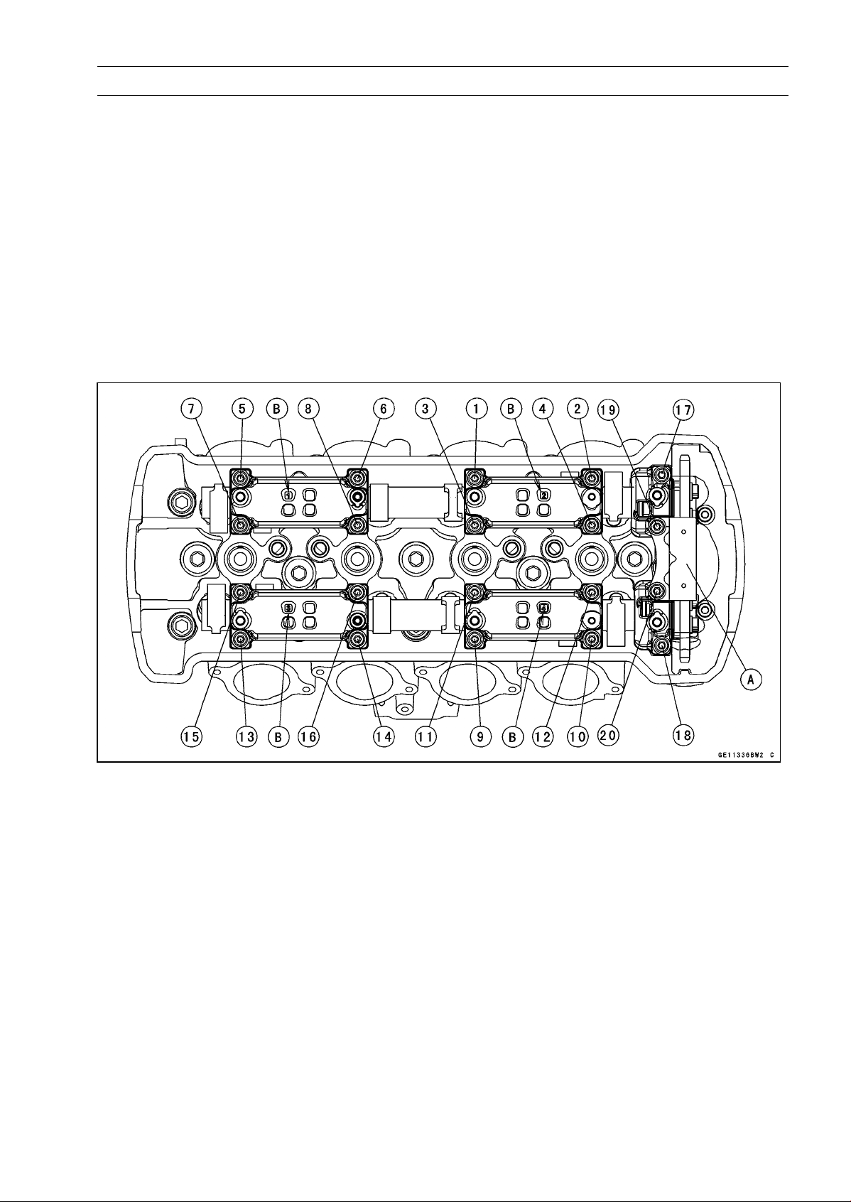
ENGINE TOP END 5-23
Camshaft, Camshaft Chain
•
Before installing the camshaft caps and upper chain
guide, install the camshaft chain tensioner body tem-
porarily (see Camshaft Chain Tensioner Installation).
•
Install the camshaft caps and upper camshaft chain guide
[A] as shown in the figure.
Identification No. 1 ∼ 4 (Camshaft Cap) [B]
•
First tighten the all camshaft cap bolts and upper
camshaft chain guide bolts evenly to seat the camshaft
in place, then tighten all bolts following the specified
tightening sequence.
Torque - Camshaft Cap Bolts [1
∼ 18]: 12 N·m (1.2 kgf·m,
106 in·lb)
Upper Camshaft Chain Guide Bolts [19, 20]: 12
N·m (1.2 kgf·m, 106 in·lb)
•
Install the camshaft chain tensioner (see Camshaft Chain
Tensioner Installation).
•
Turn the crankshaft 2 turns clockwise to allow the ten-
sioner to expand and recheck the camshaft chain timing.
•
Install the cylinder head cover (see Cylinder Head Cover
Installation).
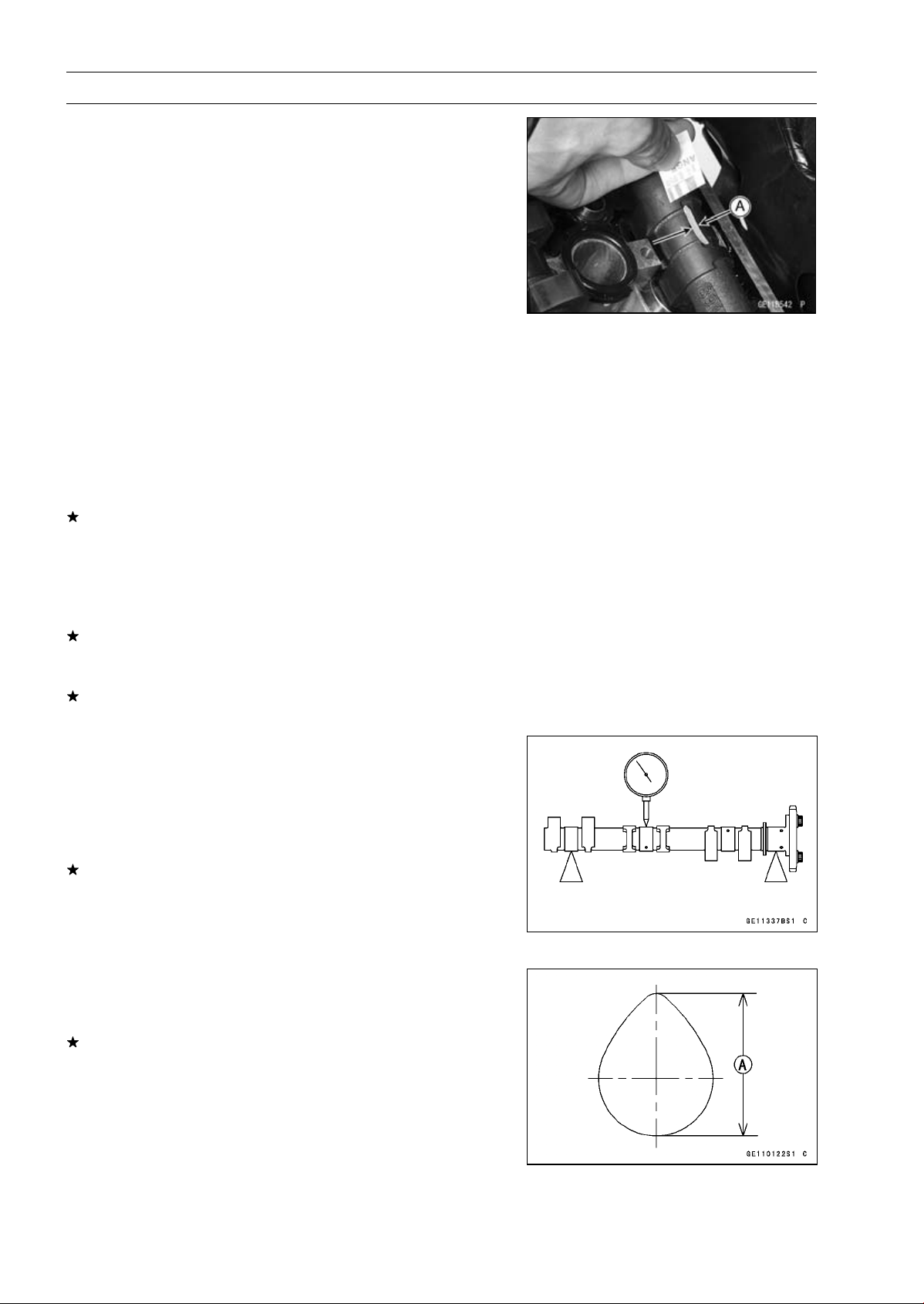
5-24 ENGINE TOP END
Camshaft, Camshaft Chain
Camshaft, Camshaft Cap Wear Inspection
•
Remove:
Upper Chain Guide (see Camshaft Removal)
Camshaft Caps (see Camshaft Removal)
•
Cut strips of plastigage (press gauge) to journal width.
Place a strip on each journal parallel to the camshaft in-
stalled in the correct position.
•
Measure each clearance between the camshaft journal
and the camshaft cap using plastigage [A].
•
Tighten the camshaft cap bolts (see Camshaft Installa-
tion).
NOTE
○
Do not turn the camshaft when the plastigage is be-
tween the journal and camshaft cap.
Camshaft Journal, Camshaft Cap Clearance
Standard: 0.038
∼ 0.081 mm (0.0015 ∼ 0.0032 in.)
Service Limit: 0.17 mm (0.0067 in.)
If any clearance exceeds the service limit, measure the
diameter of each camshaft journal with a micrometer.
Camshaft Journal Diameter
Standard: 23.940
∼ 23.962 mm (0.9425 ∼ 0.9434 in.)
Service Limit: 23.91 mm (0.9413 in.)
If the camshaft journal diameter is less than the service
limit, replace the camshaft with a new one and measure
the clearance again.
If the clearance still remains out of the limit, replace the
cylinder head unit.
Camshaft Runout Inspection
•
Remove the camshafts (see Camshaft Removal).
•
Set the camshaft in a camshaft alignment jig or on V
blocks.
•
Measure runout with a dial gauge at the specified place
as shown in the figure.
If the runout exceeds the service limit, replace the shaft.
Camshaft Runout
Standard: TIR 0.02 mm (0.0008 in.) or less
Service Limit: TIR 0.1 mm (0.004 in.)
Cam Wear Inspection
•
Remove the camshafts (see Camshaft Removal).
•
Measure the height [A] of each cam with a micrometer.
If the cams are worn down past the service limit, replace
the camshaft.
Cam Height
Standard:
Exhaust
33.743
∼ 33.857 mm (1.3285 ∼ 1.3330 in.)
Intake
34.743
∼ 34.857 mm (1.3678 ∼ 1.3723 in.)
Service Limit:
Exhaust
33.64 mm (1.324 in.)
Intake
34.64 mm (1.364 in.)

ENGINE TOP END 5-25
Camshaft, Camshaft Chain
Camshaft Chain Removal
•
Split the crankcase (see Crankcase Splitting in the Crank-
shaft/Transmission chapter).
•
Remove the camshaft chain [A] from the crankshaft
sprocket.
Camshaft Chain Installation
NOTE
○
The crankshaft, camshaft chain and camshaft sprock-
ets are different between the early production models
(Engine Number:
∼
ZRT00DE016592), the late produc-
tion models (Engine Number: ZRT00DE016593
∼
) and
ZR1000DD/ED.
○
Do not use these parts in a combination of the ear-
lier production models, later production models and
ZR1000DD/ED (see the table of specification for the
Crankshaft, Camshaft Chain and Camshaft Sprocket
Selection) .
•
Installation is the reverse of removal.
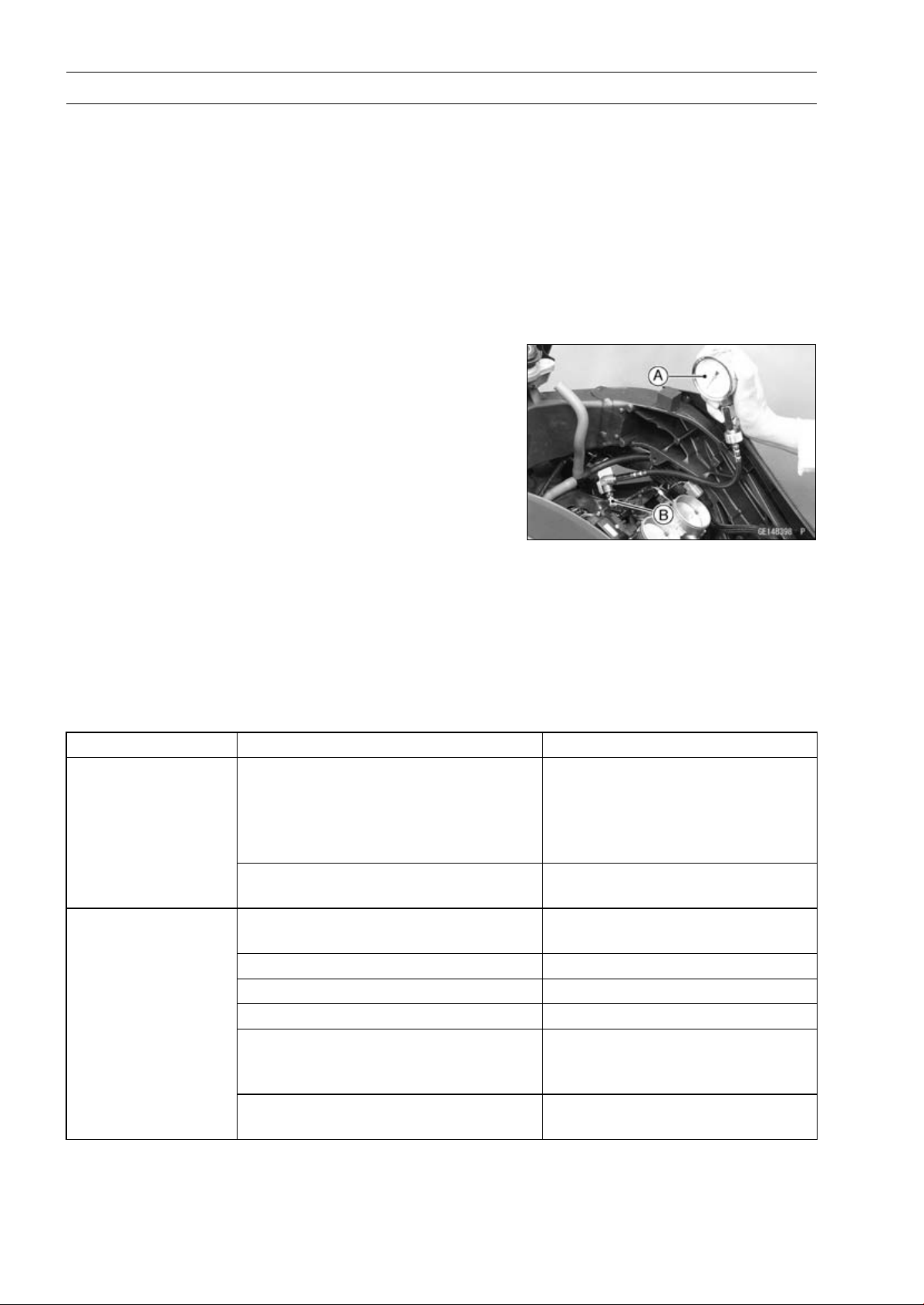
5-26 ENGINE TOP END
Cylinder Head
Cylinder Compression Measurement
NOTE
○
Use the battery which is fully charged.
•
Warm up the engine thoroughly.
•
Stop the engine.
•
Remove:
Stick Coils (see Stick Coil Removal in the Electrical Sys-
tem chapter)
Spark Plugs (see Spark Plug Replacement in the Peri-
odic Maintenance chapter)
•
Attach the compression gauge [A] and adapter [B] firmly
into the spark plug hole.
○
Using the starter motor, turn the engine over with the throt-
tle fully open until the compression gauge stops rising; the
compression is the highest reading obtainable.
Special Tools - Compression Gauge, 20 kgf/cm²: 57001-221
Compression Gauge Adapter, M10 × 1.0:
57001-1601
L-Shape Hose: 57001-1606
Cylinder Compression
Usable Range:
966
∼ 1 478 kPa (9.9 ∼ 15.1 kgf/cm²,
140
∼ 214 psi) at 280 r/min (rpm)
•
Repeat the measurement for the other cylinders.
•
Install the spark plugs.
Torque - Spark Plugs: 13 N·m (1.3 kgf·m, 115 in·lb)
○
The following table should be consulted if the obtainable compression reading is not within the us-
able range.
Problem Diagnosis Remedy (Action)
Carbon accumulation on piston and in
combustion chamber possibly due to
damaged valve stem oil seal and/or
damaged piston oil rings (This may be
indicated by white exhaust smoke).
Remove the carbon deposits
and replace damaged parts if
necessary.
Cylinder compression
is higher than usable
range
Incorrect cylinder head gasket
thickness
Replace the gasket with a standard
part.
Gas leakage around cylinder head
Replace damaged check gasket
and cylinder head warp.
Bad condition of valve seating Repair if necessary.
Incorrect valve clearance Adjust the valve clearance.
Incorrect piston/cylinder clearance Replace the piston and/or cylinder.
Piston seizure Inspect the cylinder and
replace/repair the cylinder and/or
piston as necessary.
Cylinder compression
is lower than usable
range
Bad condition of piston ring and/or
piston ring grooves.
Replace the piston and/or the
piston rings.
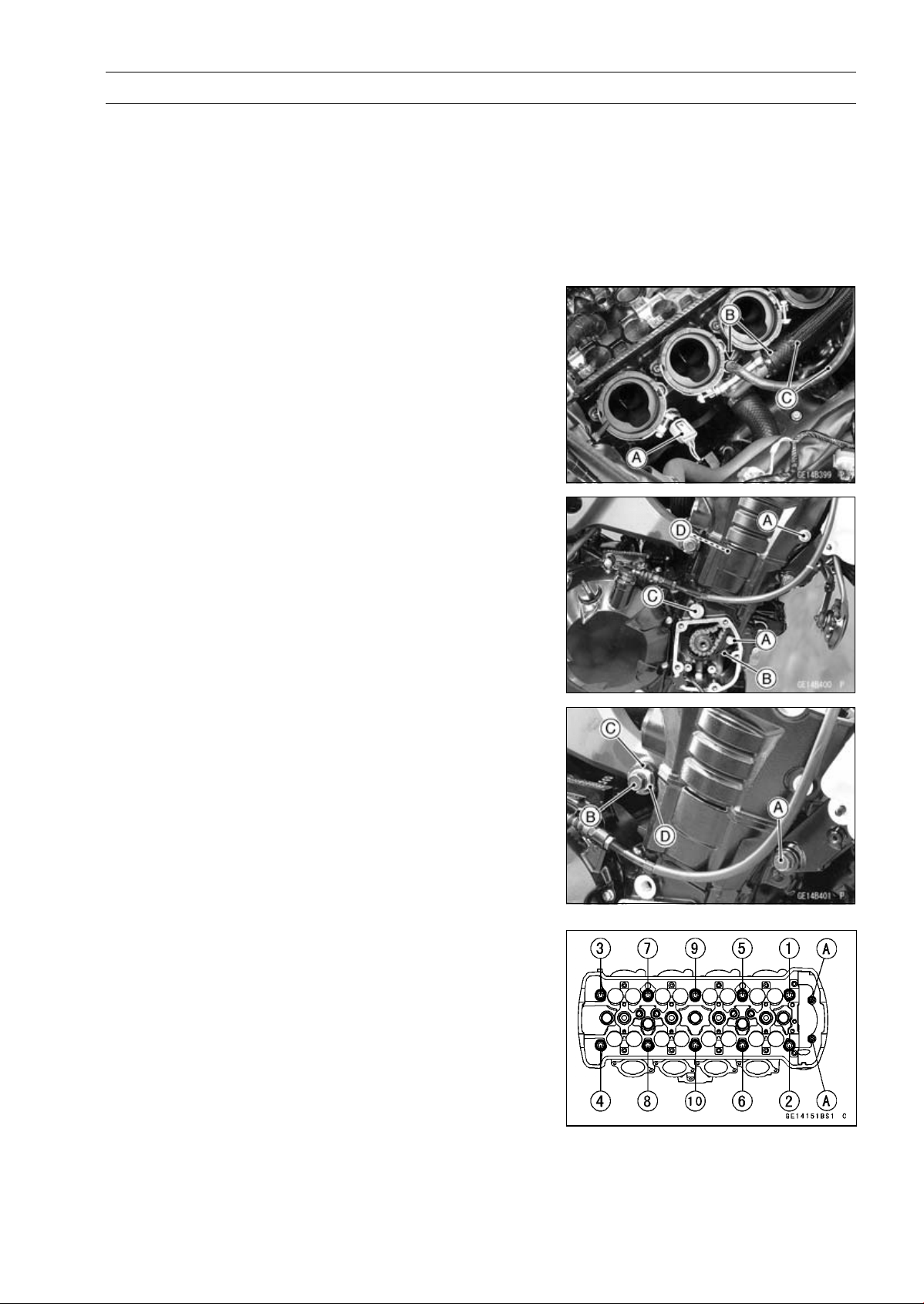
ENGINE TOP END 5-27
Cylinder Head
Cylinder Head Removal
•
Remove:
Coolant (Drain, see Coolant Change in the Periodic
Maintenance chapter)
Camshafts (see Camshaft Removal)
Throttle Body Assy (see Throttle Body Assy Removal in
the Fuel System (DFI) chapter)
Exhaust Pipe (see Exhaust Pipe Removal)
•
Disconnect the water temperature sensor connector [A].
•
Remove:
Clamps [B]
Water Hoses [C]
•
Remove:
Timing Rotor (see Timing Rotor Removal in the Electrical
System chapter)
Front Camshaft Chain Guide Bolts [A]
Front Camshaft Chain Guide [B]
Rear Camshaft Chain Guide Bolt [C]
Rear Camshaft Chain Guide [D]
•
Loosen:
Lower Engine Bracket Bolts (Both Sides) [A]
Upper Engine Mounting Bolts (Left)
•
Remove:
Upper Engine Mounting Bolts (Right) [B]
•
Loosen:
Upper Adjusting Collar Locknut [C]
Special Tool - Engine Mount Nut Wrench: 57001-1450
•
Loosen:
Upper Adjusting Collar [D]
•
Remove the M6 cylinder head bolts [A].
•
Loosen the M10 cylinder head bolts as shown sequence
[1 ∼ 10] in the figure, and remove them with washers.
•
Remove the cylinder head.
Cylinder Head Installation
NOTE
○
The camshaft cap is machined with the cylinder head,
so if a new cylinder head is installed, use the cap that
is supplied with the new head.
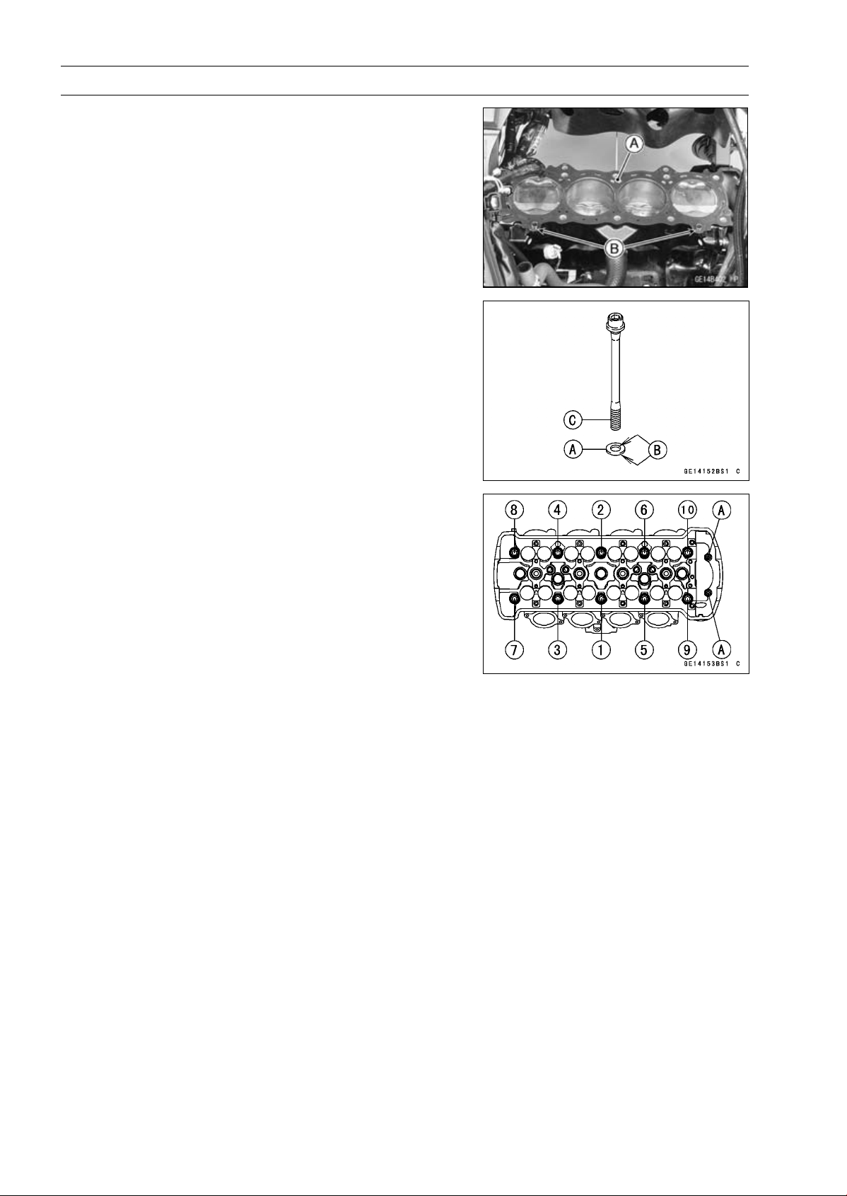
5-28 ENGINE TOP END
Cylinder Head
•
Replace the cylinder head gasket [A] with a new one.
•
Install the dowel pins [B] and cylinder head gasket.
•
Replace the cylinder head bolt washers [A] with new ones.
•
Apply molybdenum disulfide oil solution to both sides [B]
of the cylinder head bolt washers and threads [C] of the
bolts.
•
Tighten the M10 cylinder head bolts following the tighten-
ing sequence [1 ∼ 10].
Torque - Cylinder Head Bolts (M10):
First
20 N·m (2.0 kgf·m, 15 ft·lb)
Final
54 N·m (5.5 kgf·m, 40 ft·lb)
•
Tighten:
Torque - Cylinder Head Bolts (M6) [A]: 12 N·m (1.2 kgf·m,
106 in·lb)
Upper Adjusting Collar: 9.8 N·m (1.0 kgf·m, 87
in·lb)
Upper Adjusting Collar Locknut: 4.9 N·m (5.0
kgf·m, 36 ft·lb)
Upper Engine Mounting Bolts: 44 N·m (4.5 kgf·m,
32 ft·lb)
Lower Engine Bracket Bolts: 44 N·m (4.5 kgf·m,
32 ft·lb)
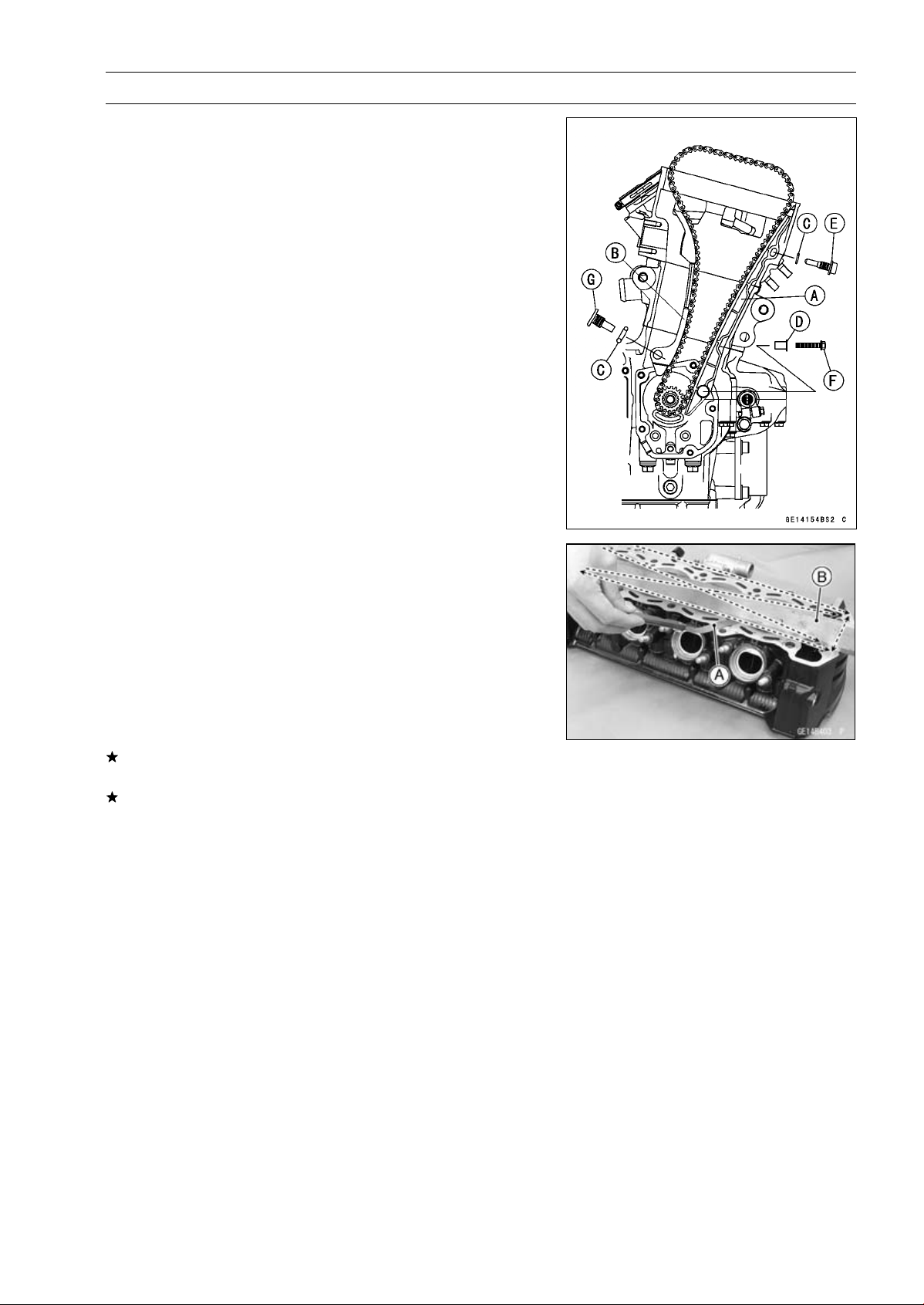
ENGINE TOP END 5-29
Cylinder Head
•
Install:
Front Camshaft Chain Guide [A]
Rear Camshaft Chain Guide [B]
New O-rings [C]
Collar [D]
○
Apply grease to the new O-ring.
•
Tighten:
Torque - Front Camshaft Chain Guide Bolt (Upper) [E]: 25
N·m (2.5 kgf·m, 18 ft·lb)
Front Camshaft Chain Guide Bolt (Lower) [F]: 12
N·m (1.2 kgf·m, 106 in·lb)
Rear Camshaft Chain Guide Bolt [G]: 25 N·m (2.5
kgf·m, 18 ft·lb)
•
Install the removed parts (see appropriate chapters).
Cylinder Head Warp Inspection
•
Clean the cylinder head.
•
Lay a straightedge across the lower surface of the cylinder
head at several positions.
•
Use a thickness gauge [A] to measure the space between
the straightedge [B] and the head.
Cylinder Head Warp
Standard:
–––
Service Limit: 0.05 mm (0.002 in.)
If the cylinder head is warped more than the service limit,
replace it.
If the cylinder head is warped less than the service limit,
repair the head by rubbing the lower surface on emery
paper secured to a surface plate (first No. 200, then No.
400).
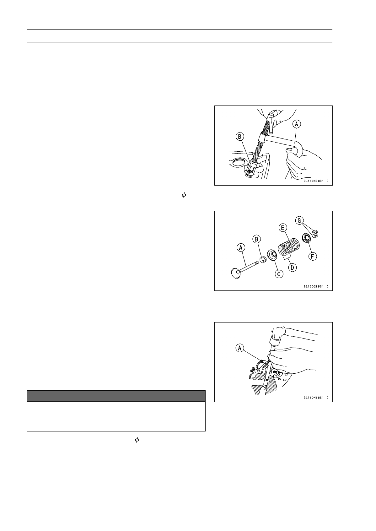
5-30 ENGINE TOP END
Valves
Valve Clearance Inspection
•
Refer to the Valve Clearance Inspection in the Periodic
Maintenance chapter.
Valve Clearance Adjustment
•
Refer to the Valve Clearance Adjustment in the Periodic
Maintenance chapter.
Valve Removal
•
Remove:
Cylinder Head (see Cylinder Head Removal)
Valve Lifter and Shim
○
Mark and record the valve lifter and shim locations so they
can be installed in their original positions.
•
Using the valve spring compressor assembly, remove the
valve.
Special Tools - Valve Spring Compressor Assembly [A]:
57001-241
Valve Spring Compressor Adapter,
24 [B]:
57001-1586
Valve Installation
•
Replace the oil seal with a new one.
•
Apply a thin coat of molybdenum disulfide grease to the
valve stem before valve installation.
•
Install the springs so that the closed coil end (unpainted
side) faces downwards.
Valve Stem [A]
Oil Seal [B]
Spring Seat [C]
Closed Coil End [D]
ValveSpring[E]
Retainer [F]
Split Keepers [G]
Valve Guide Removal
•
Remove:
Valve(seeValveRemoval)
Oil Seal
Spring Seat
•
Heat the area around the valve guide to 120 ∼ 150°C (248
∼ 302°F), and hammer lightly on the valve guide arbor [A]
to remove the guide from the top of the head.
NOTICE
Do not heat the cylinder head with a torch. This will
warp the cylinder head. Soak the cylinder head in
oil and heat the oil.
Special Tool - Valve Guide Arbor, 4.5: 57001-1331
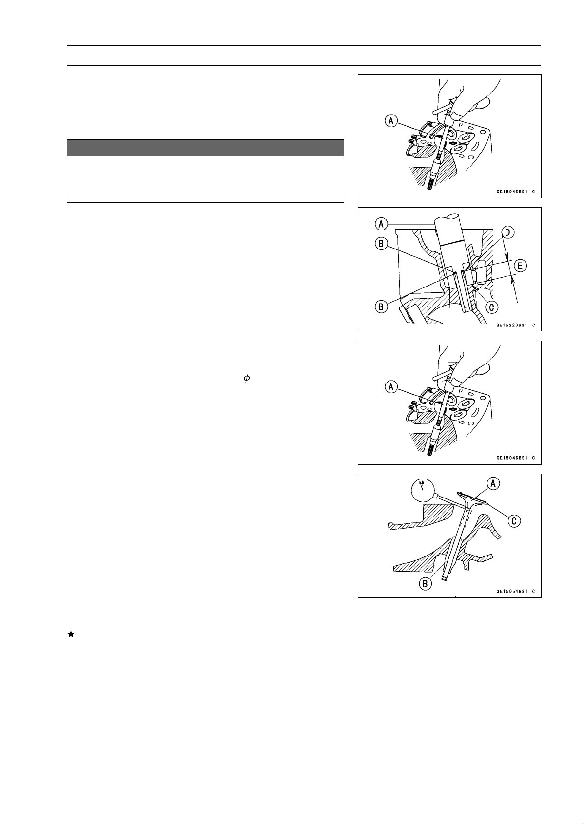
ENGINE TOP END 5-31
Valves
Valve Guide Installation
•
Apply oil to the valve guide outer surface before installa-
tion.
•
Heat the area around the valve guide hole to about 120 ∼
150°C (248 ∼ 302°F).
NOTICE
Do not heat the cylinder head with a torch. This Will
warp the cylinder head. Soak the cylinder head and
heat the oil.
•
Using the valve guide driver [A] and two washers [B],
press and insert the valve guide in until the valve guide
driver surface [C] touches the head surface [D].
12.8 ∼ 13.0 mm (0.504 ∼ 0.512 in.) [E]
Special Tools - Valve Guide Driver: 57001-1564
Washer: 57001-1612
•
Ream the valve guide with valve guide reamer [A], even
if the old guide is reused.
Special Tool - Valve Guide Reamer,
4.5: 57001-1333
Valve-to-Guide Clearance Measurement (Wobble
Method)
If a small bore gauge is not available, inspect the valve
guide wear by measuring the valve to valve guide clearance
with the wobble method as indicated below.
•
Insert a new valve [A] into the guide [B] and set a dial
gauge against the stem perpendicular to it as close as
possible to the cylinder head mating surface.
•
Move the stem back and forth [C] to measure valve/valve
guide clearance.
•
Repeat the measurement in a direction at a right angle to
the first.
If the reading exceeds the service limit, replace the guide.
NOTE
○
The reading is not actual valve/valve guide clearance
because the measuring point is above the guide.
Valve/Valve Guide Clearance (Wobble Method)
Standard:
Exhaust
0.08
∼ 0.14 mm (0.0031 ∼ 0.0055 in.)
Intake
0.03
∼ 0.10 mm (0.0012 ∼ 0.0039 in.)
Service Limit:
Exhaust
0.31 mm (0.012 in.)
Intake
0.29 mm (0.011 in.)
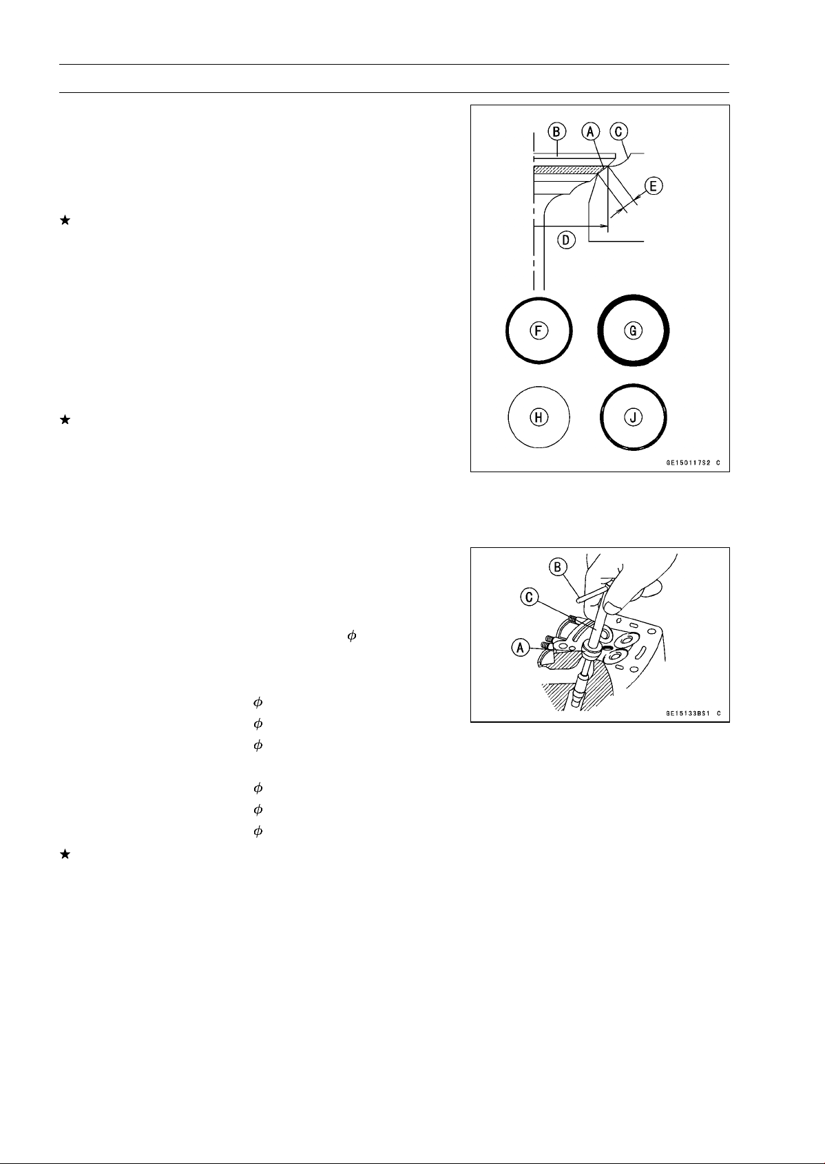
5-32 ENGINE TOP END
Valves
Valve Seat Inspection
•
Remove the valve (see Valve Removal).
•
Check the valve seating surface [A] between the valve [B]
and valve seat [C].
○
Measure the outside diameter [D] of the seating pattern
on the valve seat.
If the outside diameter is too large or too small, repair the
seat (see Seat Repair).
Valve Seating Surface Outside Diameter
Standard:
Exhaust
24.7
∼ 24.9 mm (0.972 ∼ 0.980 in.)
Intake
28.9
∼ 29.1 mm (1.138 ∼ 1.146 in.)
○
Measure the seat width [E] of the portion where there is
no build-up carbon (white portion) of the valve seat with a
vernier caliper.
Good [F]
If the width is too wide [G], too narrow [H] or uneven [J],
repair the seat (see Valve Seat Repair).
Valve Seating Surface Width
Standard:
Exhaust
0.8
∼ 1.2 mm (0.031 ∼ 0.047 in.)
Intake
0.5
∼ 1.0 mm (0.020 ∼ 0.039 in.)
Valve Seat Repair
•
Repair the valve seat with the valve seat cutters [A].
Special Tools - Valve Seat Cutter Holder Bar [B]: 57001
-1128
Valve Seat Cutter Holder,
4.5 [C]: 57001
-1330
[For Exhaust Valve Seat]
Valve Seat Cutter, 45° -
27.5: 57001-1114
Valve Seat Cutter, 32° -
28: 57001-1119
Valve Seat Cutter, 60° -
27: 57001-1409
[For Intake Valve Seat]
Valve Seat Cutter, 45° -
32: 57001-1115
Valve Seat Cutter, 32° -
33: 57001-1199
Valve Seat Cutter, 60° -
33: 57001-1334
If the manufacturer’s instructions are not available, use
the following procedure.
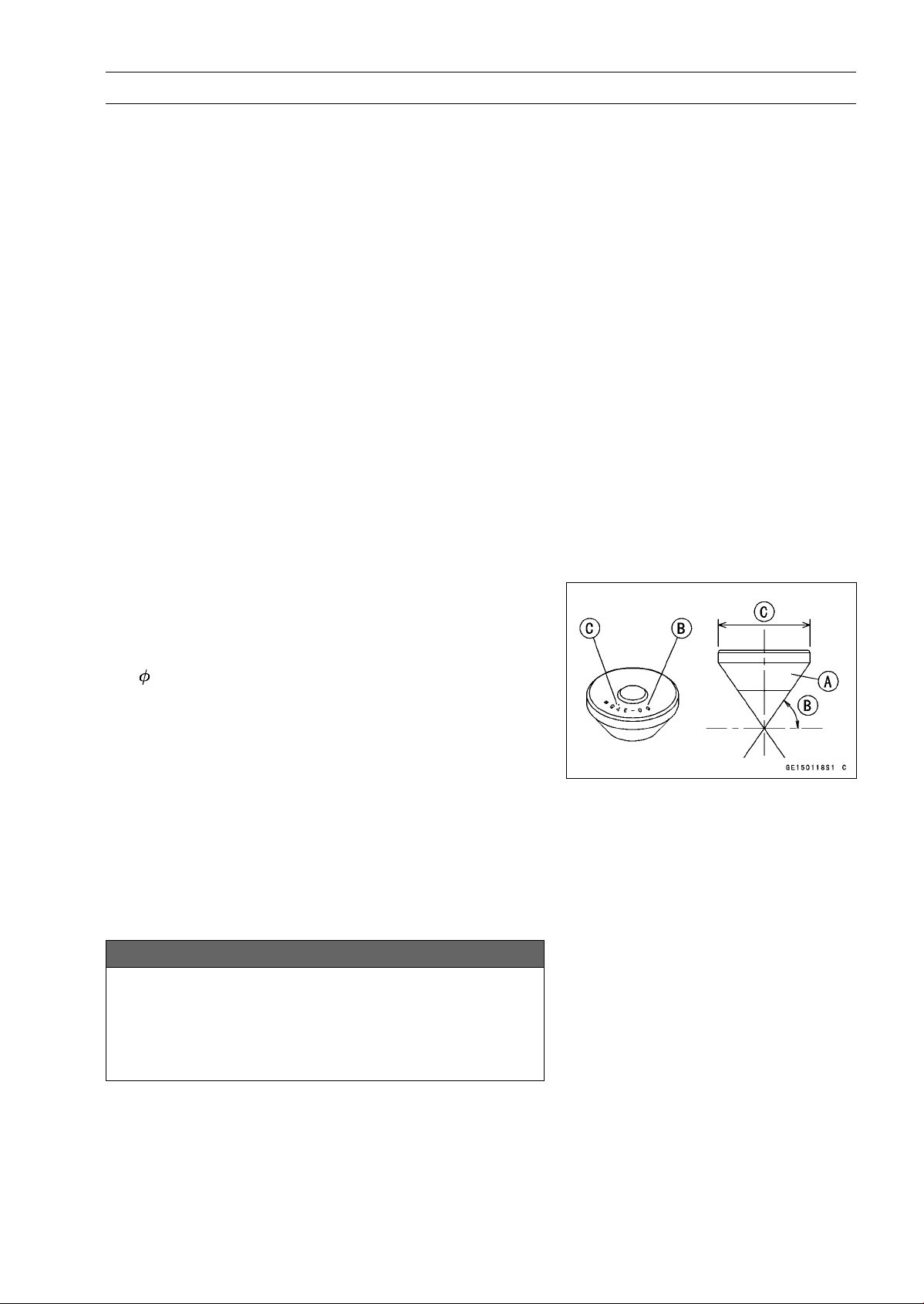
ENGINE TOP END 5-33
Valves
Seat Cutter Operation Care
1. This valve seat cutter is developed to grind the valve for
repair. Therefore the cutter must not be used for other
purposes than seat repair.
2. Do not drop or shock the valve seat cutter, or the dia-
mond particles may fall off.
3. Do not fail to apply engine oil to the valve seat cutter
before grinding the seat surface. Also wash off ground
particles sticking to the cutter with washing oil.
NOTE
○
Do not use a wire brush to remove the metal particles
from the cutter. It will take off the diamond particles.
4. Setting the valve seat cutter holder in position, operate
the cutter in one hand. Do not apply too much force to
the diamond portion.
NOTE
○
Prior to grinding, apply engine oil to the cutter and dur-
ing the operation, wash off any ground particles sticking
to the cutter with washing oil.
5. After use, wash it with washing oil and apply thin layer
of engine oil before storing.
Marks Stamped on the Cutter
The marks stamped on the back of the cutter [A] represent
the following.
60° ........................... Cutter angle [B]
37.5
....................... Outer diameter of cutter [C]
Operating Procedures
•
Clean the seat area carefully.
•
Coat the seat with machinist’s dye.
•
Fit a 45° cutter into the holder and slide it into the valve
guide.
•
Press down lightly on the handle and turn it right or left.
Grind the seating surface only until it is smooth.
NOTICE
Do not grind the seat too much. Overgrinding will
reduce valve clearance by sinking the valve into the
head. If the valve sinks too far into the head, it will
be impossible to adjust the clearance, and the cylin-
der head must be replaced.
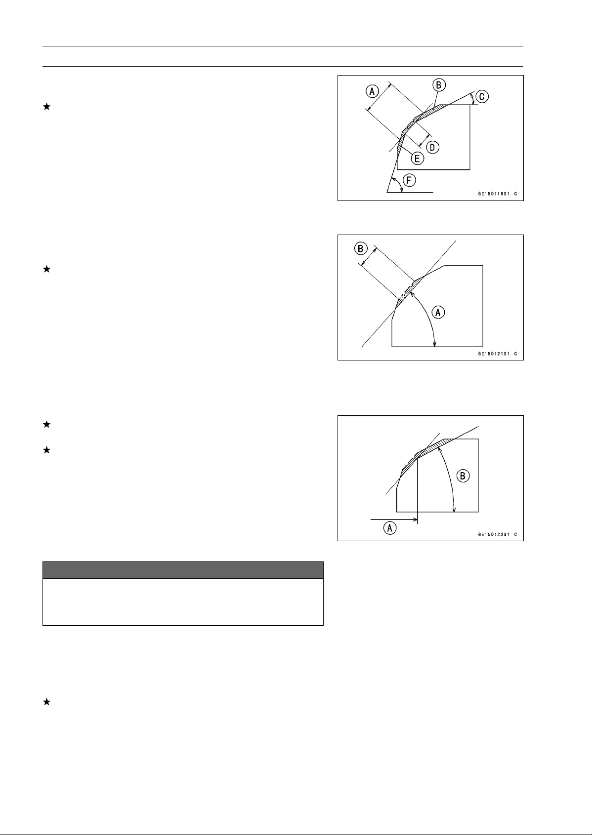
5-34 ENGINE TOP END
Valves
•
Measure the outside diameter of the seating surface with
a vernier caliper.
If the outside diameter of the seating surface is too small,
repeat the 45° grind until the diameter is within the spec-
ified range.
Widened Width [A] of engagement by machining with
45° cutter
Ground Volume [B] by 32° cutter
32° [C]
Correct Width [D]
Ground Volume [E] by 60° cutter
60° [F]
•
Measure the outside diameter of the seating surface with
a vernier caliper.
If the outside diameter of the seating surface is too small,
repeat the 45° grind [A] until the diameter is within the
specified range.
Original Seating Surface [B]
NOTE
○
Remove all pittings of flaws from 45° ground surface.
○
After grinding with 45° cutter, apply thin coat of machin-
ist’s dye to seating surface. This makes seating surface
distinct and 32° and 60° grinding operation easier.
○
When the valve guide is replaced, be sure to grind with
45° cutter for centering and good contact.
If the outside diameter [A] of the seating surface is too
large, make the 32° grind described below.
If the outside diameter of the seating surface is within the
specified range, measure the seat width as described be-
low.
•
Grind the seat at a 32° angle [B] until the seat outside
diameter is within the specified range.
○
To make the 32° grind, fit a 32° cutter into the holder, and
slide it into the valve guide.
○
Turn the holder one turn at a time while pressing down
very lightly. Check the seat after each turn.
NOTICE
The 32° cutter removes material very quickly.
Check the seat outside diameter frequently to pre-
vent overgrinding.
○
After making the 32° grind, return to the seat outside di-
ameter measurement step above.
•
To measure the seat width, use a vernier caliper to mea-
sure the width of the 45° angle portion of the seat at sev-
eral places around the seat.
If the seat width is too narrow, repeat the 45° grind until
the seat is slightly too wide, and then return to the seat
outside diameter measurement step above.
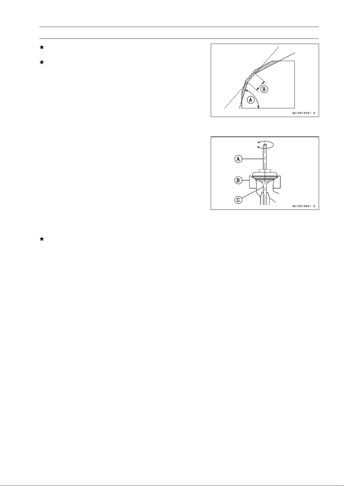
ENGINE TOP END 5-35
Valves
If the seat width is too wide, make the 60° [A] grind de-
scribed below.
If the seat width is within the specified range, lap the valve
to the seat as described below.
•
Grind the seat at a 60° angle until the seat width is within
the specified range.
○
To make the 60° grind, fit 60° cutter into the holder, and
slide it into the valve guide.
○
Turn the holder, while pressing down lightly.
○
After making the 60° grind, return to the seat width mea-
surement step above.
Correct Width [B]
•
Lap the valve to the seat, once the seat width and outside
diameter are within the ranges specified above.
○
Put a little coarse grinding compound on the face of the
valve in a number of places around the valve head.
○
Spin the valve against the seat until the grinding com-
pound produces a smooth, matched surface on both the
seat and the valve.
○
Repeat the process with a fine grinding compound.
Lapper [A]
Valve Seat [B]
Valve [C]
•
The seating area should be marked about in the middle
of the valve face.
If the seat area is not in the right place on the valve, check
to be sure the valve is the correct part. If it is, it may have
been refaced too much; replace it.
•
Be sure to remove all grinding compound before assem-
bly.
•
When the engine is assembled, be sure to adjust the valve
clearance (see Valve Clearance Inspection in the Periodic
Maintenance chapter).
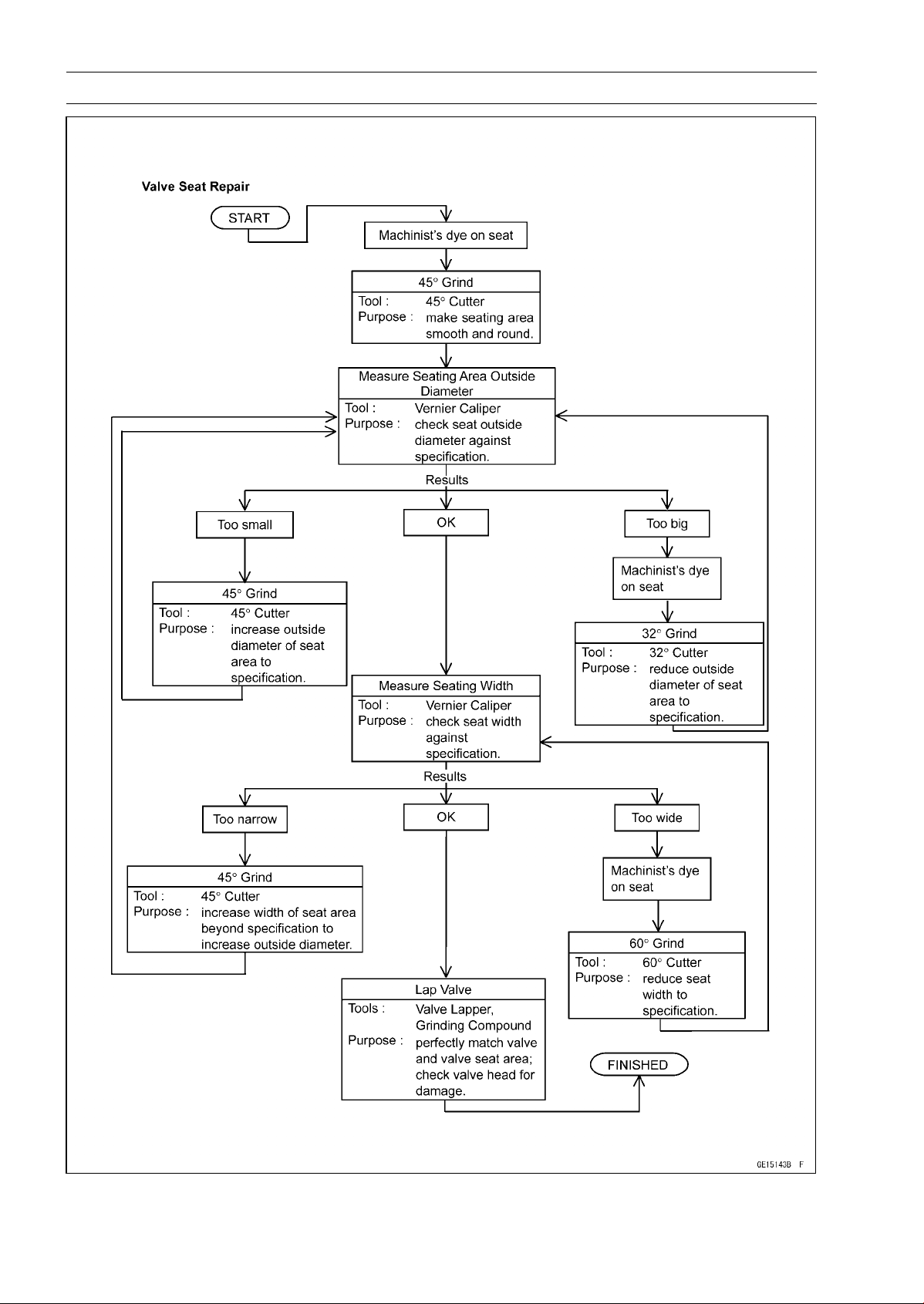
5-36 ENGINE TOP END
Valves
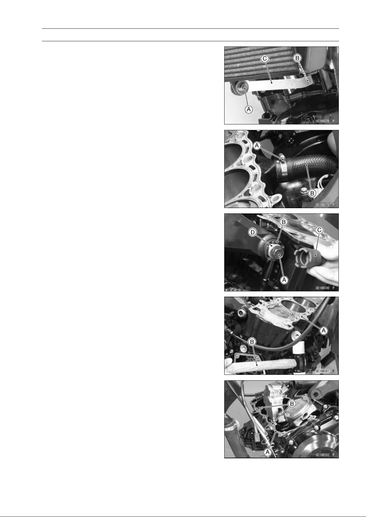
ENGINE TOP END 5-37
Cylinder, Pistons
Cylinder Removal
•
Remove:
Lower Radiator Bolt [A]
Radiator Bracket Bolt [B]
Radiator Bracket [C]
Cylinder Head (see Cylinder Head Removal)
Engine Bracket (see Engine Removal in the Engine Re-
moval/Installation chapter)
•
Remove:
Water Hose Clamp Screw (Loosen) [A]
Water Hose [B]
•
Remove:
Upper Engine Mounting Bolts (Both Sides) [A]
•
Loosen:
Upper Adjusting Collar Locknut [B]
Special Tool - Engine Mount Nut Wrench [C]: 57001-1450
•
Loosen:
Upper Adjusting Collar [D]
•
Remove:
Cylinder [A]
NOTE
○
If it is hard to remove it, tap lightly using a plastic-faced
mallet [B].
Cylinder Installation
NOTE
○
If a new cylinder is used, use new piston ring.
•
Replace the cylinder gasket [A] with a new one.
•
Install the dowel pins [B] and new cylinder gasket.
•
Apply molybdenum disulfide oil solution to the cylinder
bore.
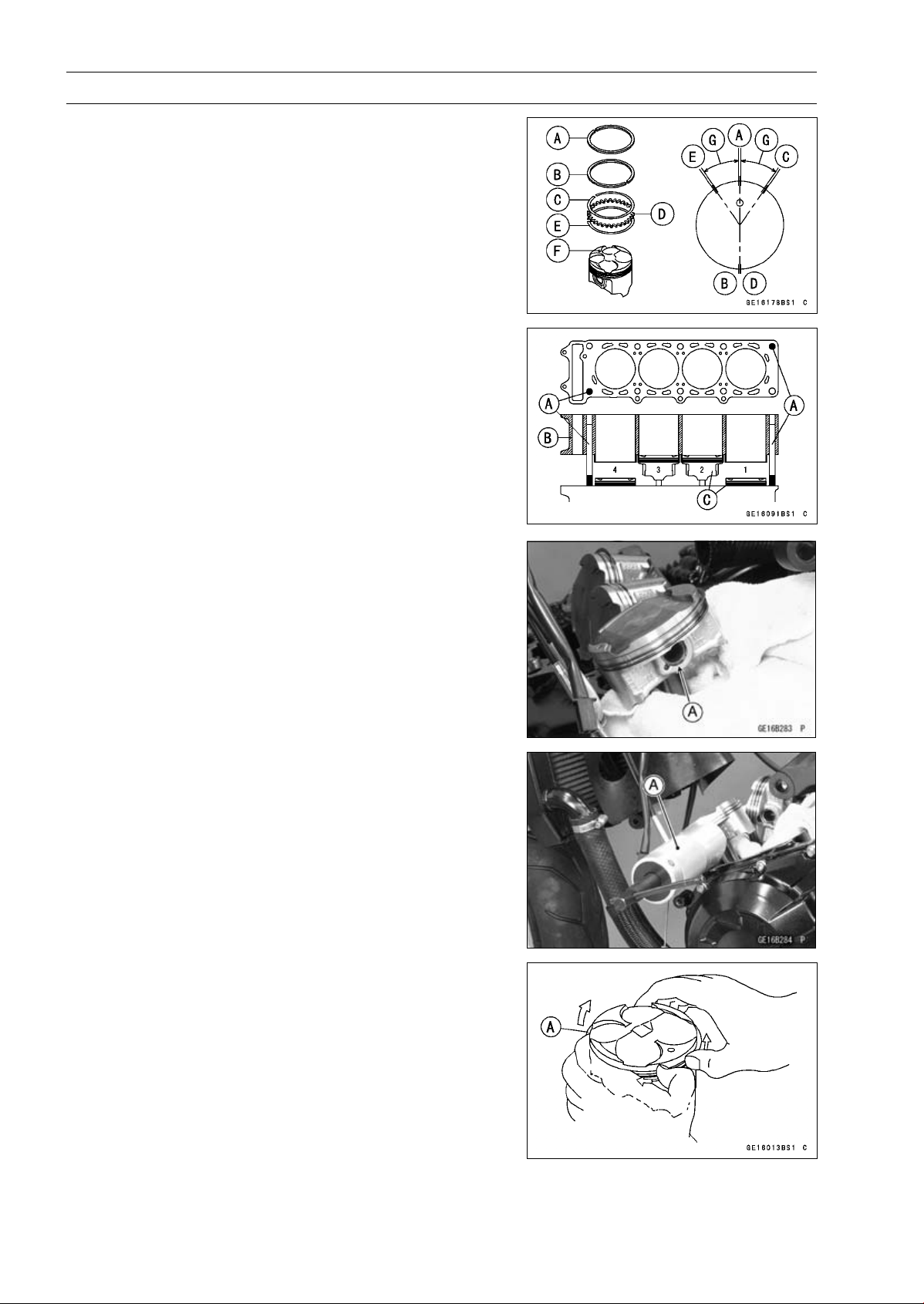
5-38 ENGINE TOP END
Cylinder, Pistons
•
The piston ring openings must be positioned as shown in
the figure. The openings of the oil ring steel rails must be
about 30 ∼ 40° of angle from the opening of the top ring.
Top R ing [A ]
Second Ring [B]
Upper Oil Ring Steel Rail [C]
Oil Ring Expander [D]
Lower Oil Ring Steel Rail [E]
Dent [F]
30 ∼ 40° [G]
•
Position the crankshaft at #2, 3 piston TDC.
•
Prepare two auxiliary head bolts with their head cut.
○
Install the two cylinder head bolts [A] diagonally in the
crankcase.
•
Install the cylinder block [B].
Pistons [C]
○
First insert the #2, 3 pistons, and then rotate the crank-
shaft at 90° angle.
•
Tighten the upper engine mounting bolts and engine
bracket bolts after cylinder head bolts tightend.
Piston Removal
•
Remove the cylinder (see Cylinder Removal).
•
Place a clean cloth under the pistons and remove the pis-
ton pin snap ring [A] from the outside of each piston.
•
Remove the piston pins.
Special Tool - Piston Pin Puller Assembly [A]: 57001-910
•
Remove the pistons.
•
Carefully spread the ring opening with your thumbs and
then push up on the opposite side of the ring [A] to remove
it.
•
Remove the 3-piece oil ring with your thumbs in the same
manner.
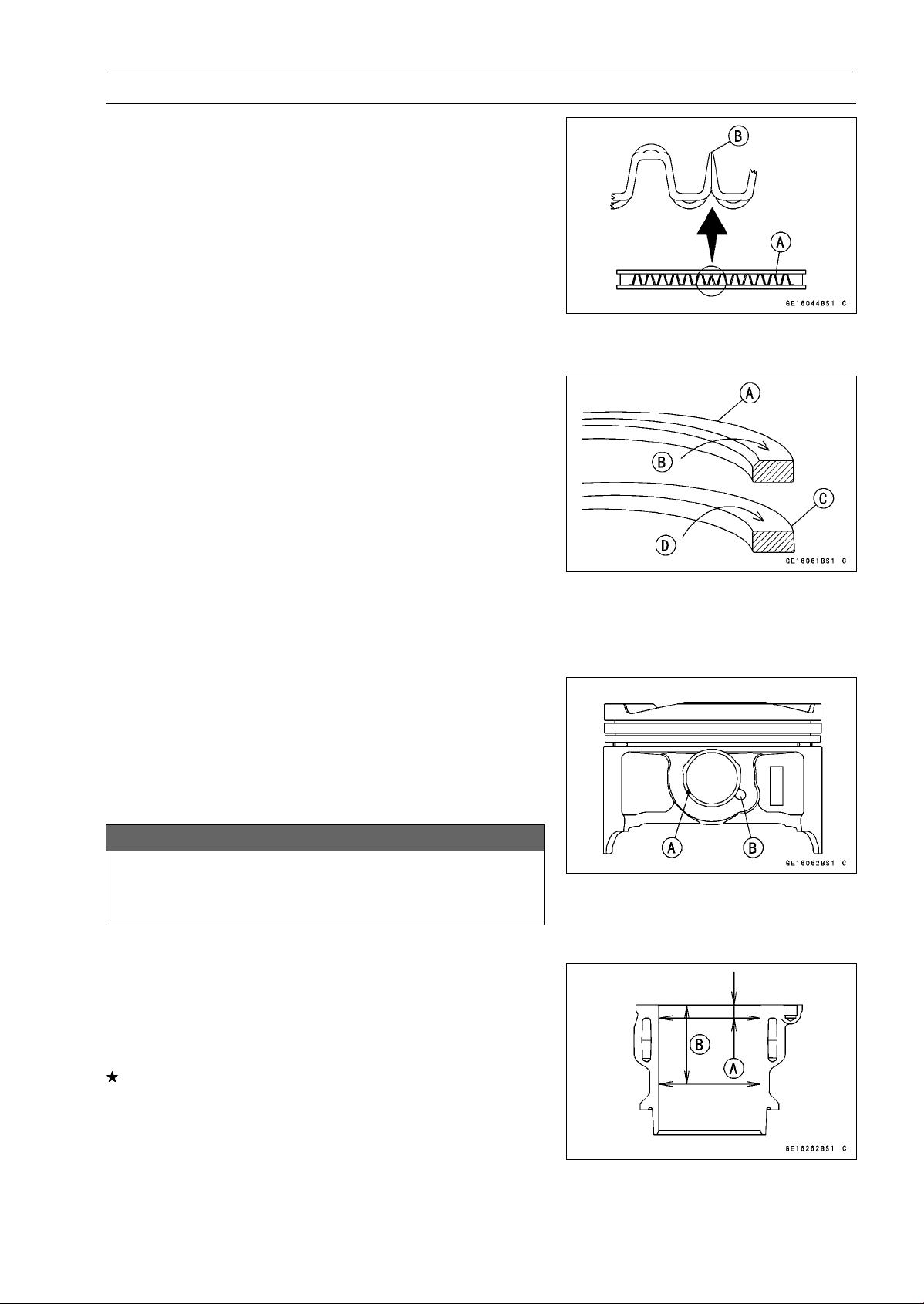
ENGINE TOP END 5-39
Cylinder, Pistons
Piston Installation
•
Apply molybdenum disulfide oil solution to the oil ring ex-
pander, and install the oil ring expander [A] in the bottom
piston ring groove so the ends [B] not butt together.
•
Apply molybdenum disulfide oil solution to the oil ring steel
rails, and install the oil ring steel rails, one above the ex-
pander and one below it.
○
Spread the rail with your thumbs, but only enough to fit
the rail over the piston.
○
Release the rail into the bottom piston ring groove.
NOTE
○
The oil ring rails have no “top” or “bottom”.
•
Do not mix up the top and second ring.
•
Install the top ring [A] so that the “1T” mark [B] faces up.
•
Install the second ring [C] so that the “2T” mark [D] faces
up.
○
Apply molybdenum disulfide oil solution to the piston
rings.
NOTE
○
If a new piston is used, use new piston ring.
•
Install the piston with its marking dent facing forward.
•
Fit a new piston pin snap ring into the side of the piston
so that the ring opening [A] does not coincide with the slit
[B] of the piston pin hole.
○
Apply molybdenum disulfide oil solution to the piston pins
and piston journals.
○
When installing the piston pin snap ring, compress it only
enough to install it and no more.
NOTICE
Do not reuse snap rings, as removal weakens and
deforms them. They could fall out and score the
cylinder wall.
•
Install the cylinder (see Cylinder Installation).
Cylinder Wear Inspection
•
Since there is a difference in cylinder wear in different di-
rections, take a side-to-side and a front-to-back measure-
ment at each of the two locations (total of four measure-
ments) as shown in the figure.
If any of the cylinder inside diameter measurements ex-
ceeds the service limit, replace the cylinder.
10 mm (0.39 in.) [A]
60 mm (2.36 in.) [B]
Cylinder Inside Diameter
Standard: 76.994
∼ 77.006 mm (3.0313 ∼ 3.0317 in.)
Service Limit: 77.09 mm (3.035 in.)
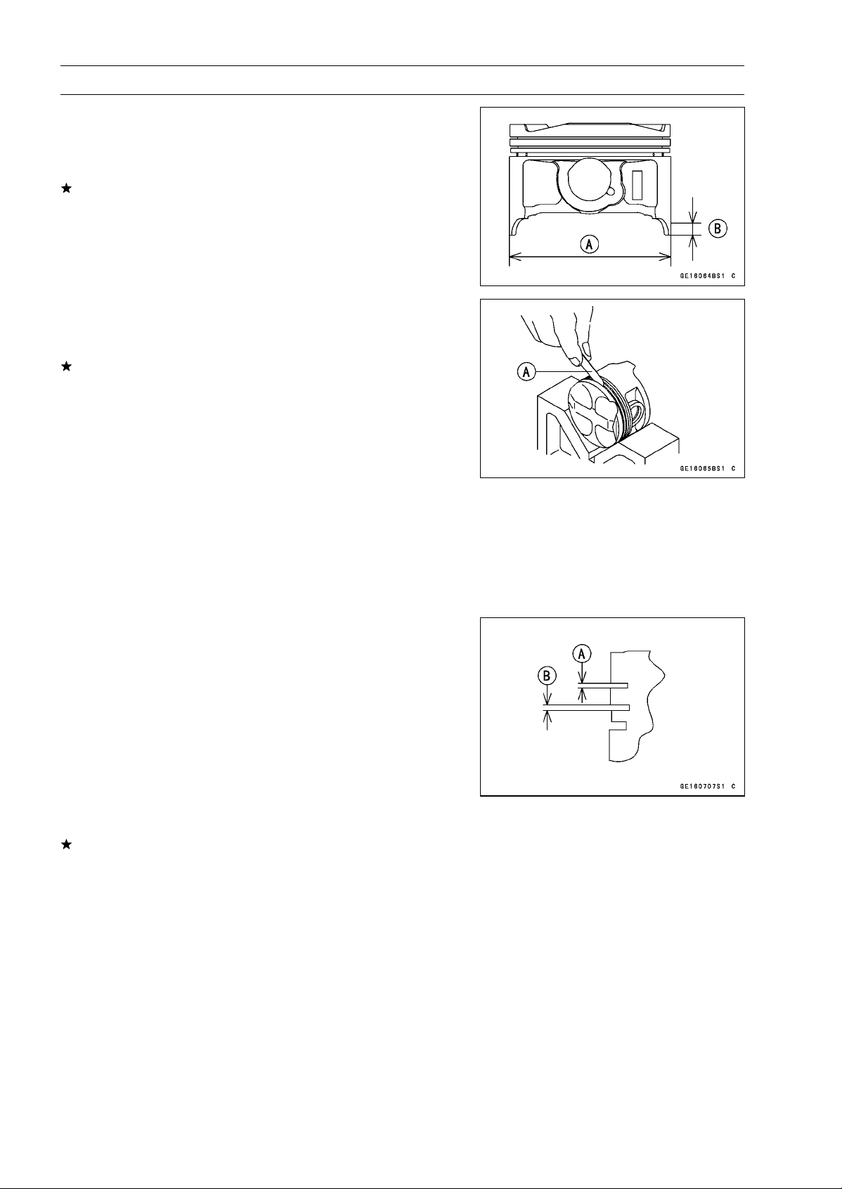
5-40 ENGINE TOP END
Cylinder, Pistons
Piston Wear Inspection
•
Measure the outside diameter [A] of each piston 11 mm
(0.43 in.) [B] up from the bottom of the piston at a right
angle to the direction of the piston pin.
If the measurement is under service limit, replace the pis-
ton.
Piston Diameter
Standard: 76.974
∼ 76.984 mm (3.0305 ∼ 3.0309 in.)
Service Limit: 76.82 mm (3.024 in.)
Piston Ring, Piston Ring Groove Wear Inspection
•
Check for uneven groove wear by inspecting the ring seat-
ing.
The rings should fit perfectly parallel to groove surfaces.
If not, replace the piston and all the piston rings.
•
With the piston rings in their grooves, make several mea-
surements with a thickness gauge [A] to determine piston
ring/groove clearance.
Piston Ring/Groove Clearance
Standard:
Top
0.03
∼ 0.07 mm (0.0012 ∼ 0.0028 in.)
Second 0.02
∼ 0.06 mm (0.0008 ∼ 0.0024 in.)
Service Limit:
Top
0.17 mm (0.0067 in.)
Second 0.16 mm (0.0063 in.)
Piston Ring Groove Width Inspection
•
Measure the piston ring groove width.
○
Use a vernier caliper at several points around the piston.
Piston Ring Groove Width
Standard:
Top [A]
0.82
∼ 0.84 mm (0.0323 ∼ 0.0331 in.)
Second [B] 0.81
∼ 0.83 mm (0.0319 ∼ 0.0327 in.)
Service Limit:
Top [A]
0.92 mm (0.0362 in.)
Second [B] 0.91 mm (0.0358 in.)
If the width of any of the two grooves are wider than the
service limit at any point, replace the piston.
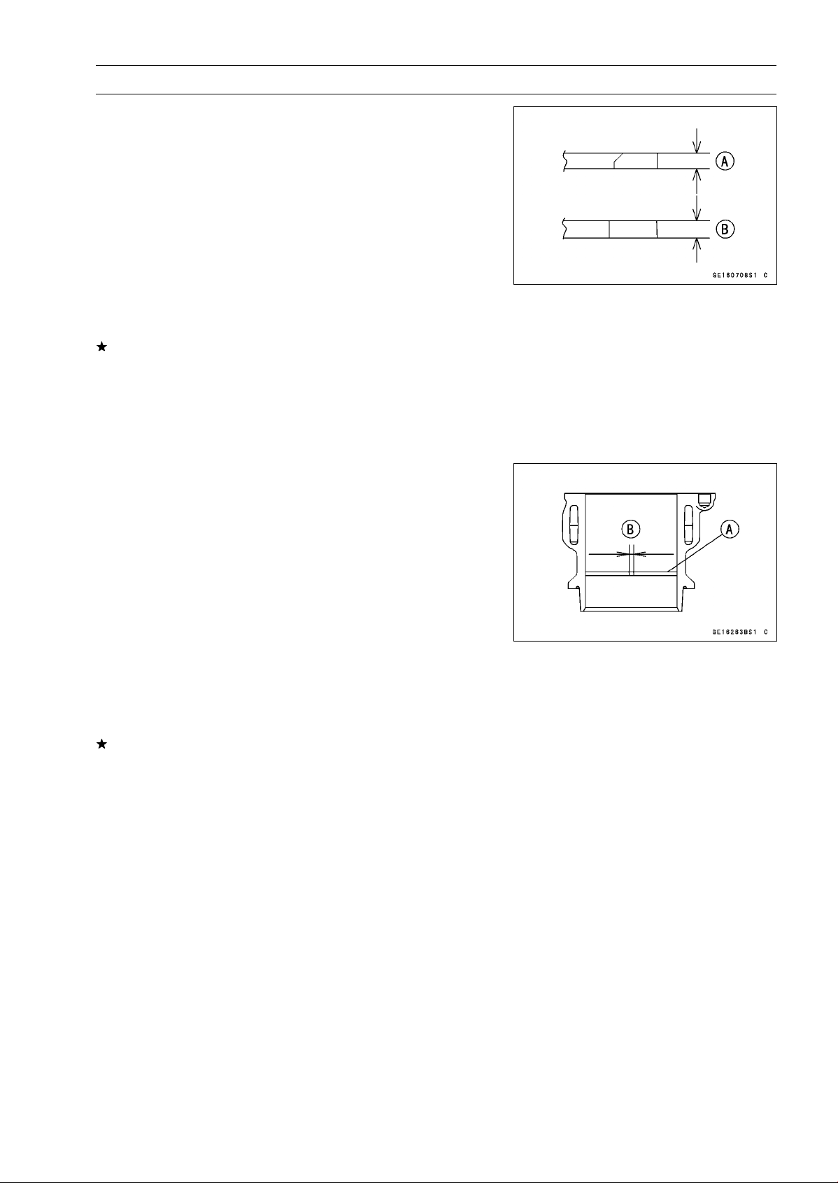
ENGINE TOP END 5-41
Cylinder, Pistons
Piston Ring Thickness Inspection
•
Measure the piston ring thickness.
○
Use the micrometer to measure at several points around
the ring.
Piston Ring Thickness
Standard:
Top [A]
0.77
∼ 0.79 mm (0.0303 ∼ 0.0311 in.)
Second [B] 0.77
∼ 0.79 mm (0.0303 ∼ 0.0311 in.)
Service Limit:
Top [A]
0.70 mm (0.028 in.)
Second [B] 0.70 mm (0.028 in.)
If any of the measurements is less than the service limit
on either of the rings, replace all the rings.
NOTE
○
When using new rings in a used piston, check for un-
even groove wear. The rings should fit perfectly parallel
to the groove sides. If not, replace the piston.
Piston Ring End Gap Inspection
•
Place the piston ring [A] inside the cylinder, using the pis-
ton to locate the ring squarely in place. Set it close to the
bottom of the cylinder, where cylinder wear is low.
•
Measure the gap [B] between the ends of the ring with a
thickness gauge.
Piston Ring End Gap
Standard:
Top
0.20
∼ 0.30 mm (0.0079 ∼ 0.0118 in.)
Second 0.38
∼ 0.48 mm (0.0150 ∼ 0.0189 in.)
Service Limit:
Top
0.6 mm (0.024 in.)
Second 0.8 mm (0.031 in.)
If the end gap of either ring is greater than the service
limit, replace all the rings.
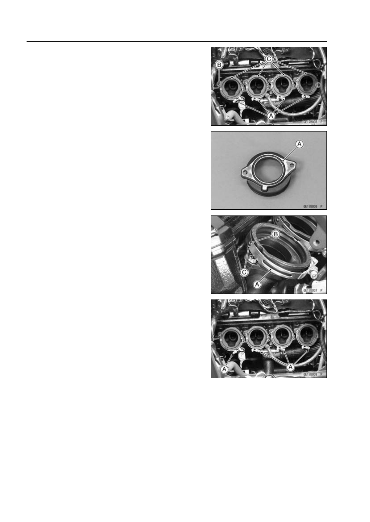
5-42 ENGINE TOP END
Throttle Body Assy Holder
Throttle Body Assy Holder Removal
•
Remove:
Throttle Body Assy (see Throttle Body Assy Removal in
the Fuel System (DFI) chapter)
Clamps [A]
Bolts [B]
Throttle Body Assy Holders [C]
Throttle Body Assy Holder Installation
•
Replace the O-rings [A] with new ones.
•
Apply grease to the O-rings, and install them.
•
Apply a non-parmanent locking agent to the throttle body
assy holder bolts.
•
Tighten:
Torque - Throttle Body Assy Holder Bolts: 12 N·m (1.2
kgf·m, 106 in·lb)
•
Install the clamps [A] so that their projections [B] fit on the
holes [C] of the holders.
○
Be sure that the clamp bolt heads [A] face as shown in
the figure.
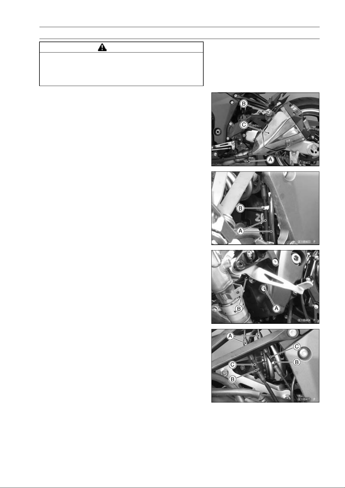
ENGINE TOP END 5-43
Muffler
WARNING
The exhaust pipe or muffler body can become ex-
tremely hot during normal operation and cause se-
vere burns. Do not remove the exhaust pipe or muf-
fler body while it is hot.
Muffler Body Removal
Left Muffler Body
•
Loosen the muffler body clamp bolt [A].
•
Remove:
Left Muffler Body Mounting Bolt [B] and Nut
Left Muffler Body [C]
Right Muffler Body
•
Clear the exhaust butterfly valve cables [A] from the clamp
[B].
•
Remove:
Rear Lower Fairing (see Rear Lower Fairing Removal in
the Frame chapter)
•
Remove the holder clamp bolt [A] to free the holder clamp
[B] from the frame.
•
Slide the dust covers [A].
•
Loosen the locknuts [B], and turn the adjusters [C] to give
the cable plenty of play.
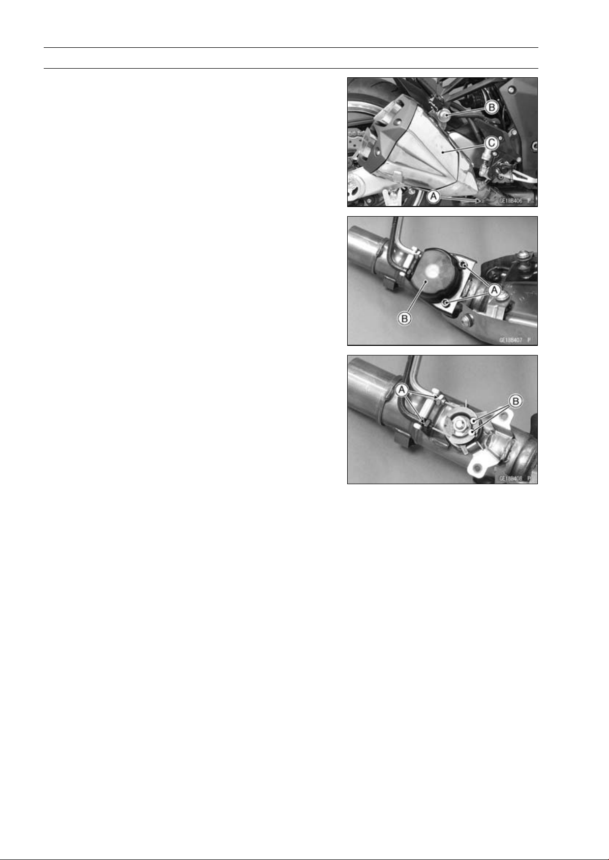
5-44 ENGINE TOP END
Muffler
•
Remove:
Clamp Bolt [A] (Loosen)
Right Muffler Body Mounting Bolt [B] and Nut
Right Muffler Body [C] (with the cable installed)
•
Remove:
Bolts [A]
Exhaust Butterfly Valve Pulley Cover [B]
•
Loosen the locknuts [A].
•
Remove the cable lower ends [B].
Muffler Body Installation
•
Replace the muffler body gaskets [A] with new ones.
•
Install the muffler body gaskets until it is bottomed so that
the inside chamfer side faces rear [B].
•
Install the muffler body clamps [C] so that the insert the
projection [D] into the clamp slit [E].
Downside [F]
Inside [G]
Viewed from Rear [H]
•
Install the exhaust butterfly valve cables (see Exhaust
Butterfly Valve Cable Installation).
•
Install the muffler bodies until it stops at the bottom sur-
face of the exhaust pipe.
•
Install the muffler body mounting bolts and nuts.
•
Tighten:
Torque - Muffler Body Mounting Bolts [I]: 34 N·m (3.5 kgf·m,
25 ft·lb)
•
Turn the muffler body clamps outward until it stops at the
slit ends.
•
Tighten:
Torque - Muffler Body Clamp Bolt [J]: 21 N·m (2.1 kgf·m, 15
ft·lb)
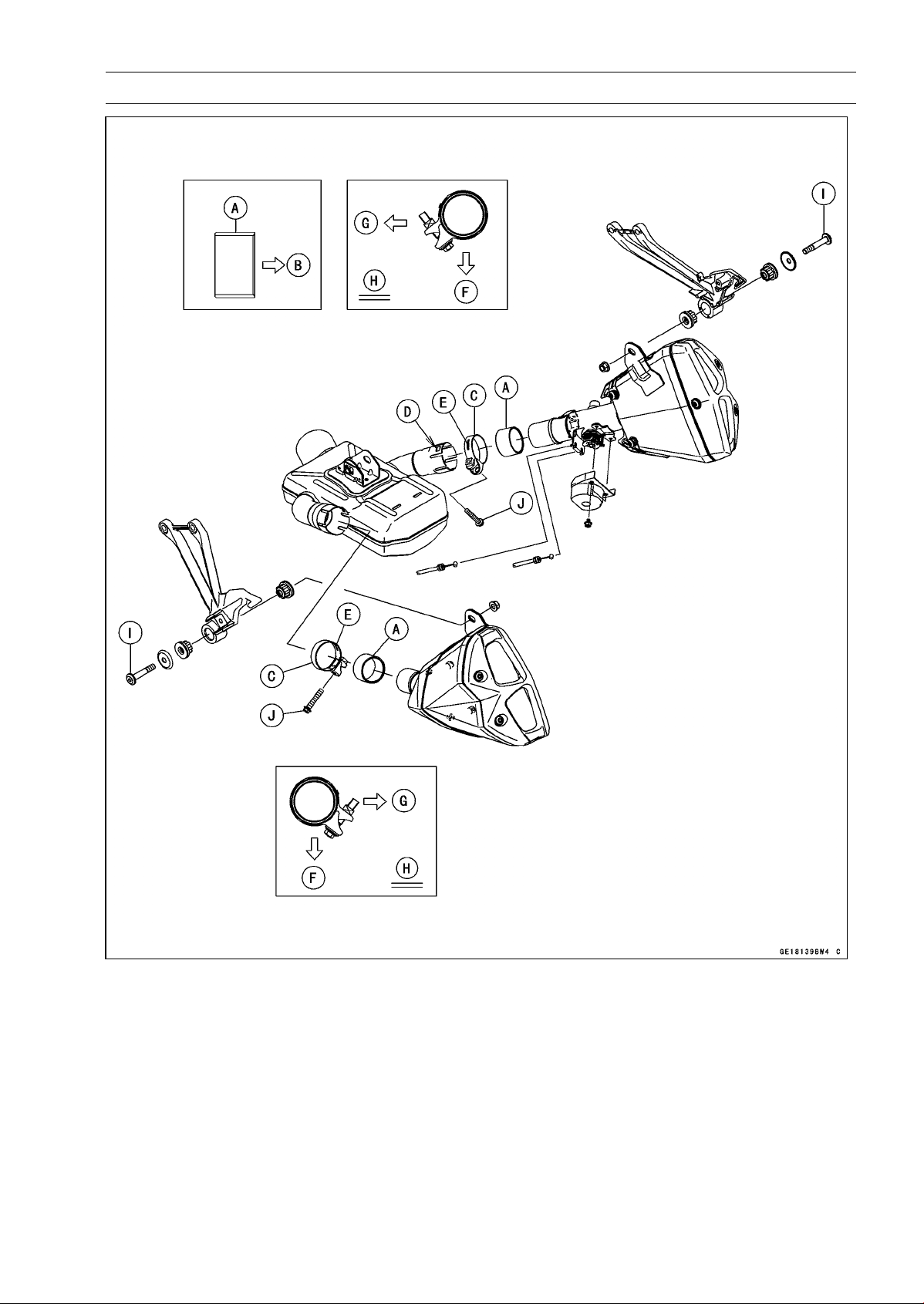
ENGINE TOP END 5-45
Muffler
•
Thoroughly warm up the engine, wait until the engine
cools down, retighten all the bolts and nuts.
•
Install the removed parts (see appropriate chapters).
○
When installing, run the cables correctly (see Cable, Wire,
and Hose Routing section in the Appendix chapter).
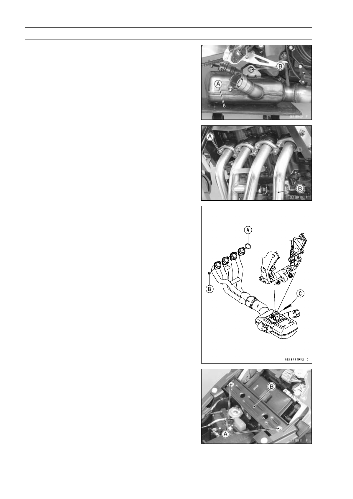
5-46 ENGINE TOP END
Muffler
Exhaust Pipe Removal
•
Remove:
Muffler Bodies (see Muffler Body Removal)
Oxygen Sensor (see Oxygen Sensor Removal
(Equipped Models) in the Electrical System chap-
ter)
•
Support the premuffler chamber with the suitable stand
[A].
•
Loosen the premuffler chamber mounting bolt [B].
•
Remove:
Exhaust Pipe Holder Nuts [A]
Exhaust Pipe (Premuffler Chamber) [B]
(In the photo, the radiator has been removed for clarity)
Exhaust Pipe Installation
•
Replace the exhaust pipe gaskets [A] with new ones and
install them.
•
Install the exhaust pipe.
•
Tighten the exhaust pipe holder nuts [B] and mounting
bolt [B].
Torque - Premuffler Chamber Mounting Bolt [C]: 34 N·m
(3.5 kgf·m, 25 ft·lb)
•
Install the muffler bodies (see Muffler Body Installation).
•
Thoroughly warm up the engine, wait until the engine
cools down, retighten all the bolts and nuts.
•
Install the removed parts (see appropriate chapters).
○
When installing, run the cables and leads correctly (see
Cable, Wire, and Hose Routing section in the Appendix
chapter).
Exhaust Butterfly Valve Cable Removal
•
Remove the cable lower ends (see Muffler Body Re-
moval).
•
Remove:
Front Seat (see Front Seat Removal in the Frame chap-
ter)
Bolts [A]
Front Seat Bracket [B]
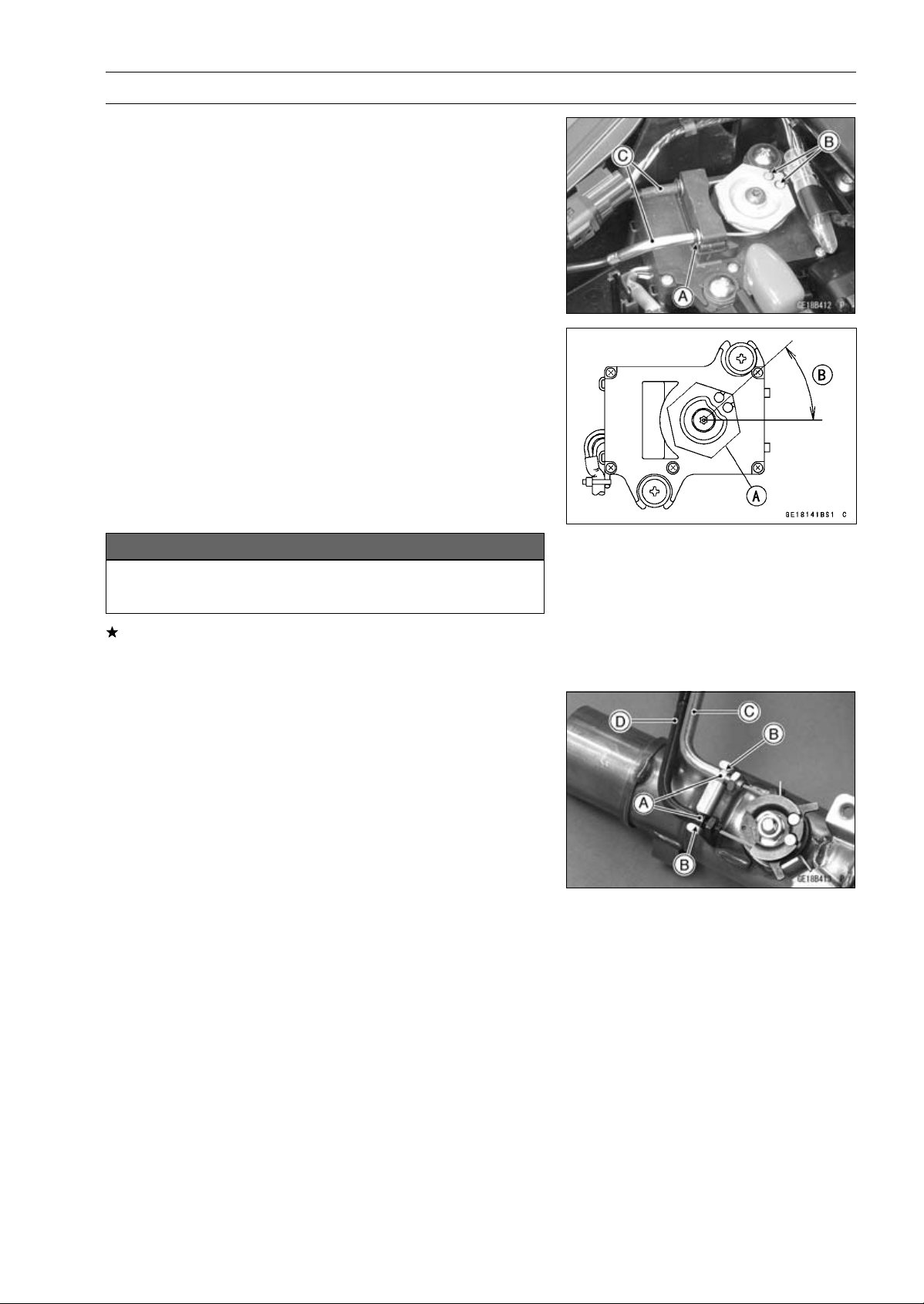
ENGINE TOP END 5-47
Muffler
•
Remove:
Clamp [A]
Exhaust Butterfly Valve Cable Upper Ends [B]
Exhaust Butterfly Valve Cables [C]
Exhaust Butterfly Valve Cable Installation
•
Confirm whether pulley [A] is an angle as shown in the
figure.
41.7° ±7° [B]
○
This position is original position of the pulley.
NOTE
○
Correct the position electrically after confirming use is
discontinued and there is no damage when differing
from the angle of shown in the figure.
NOTICE
Do not correct the pulley position with the tool,
forcibly. The actuator damage will occur.
If the angle is wrong, adjust the pulley (see Exhaust But-
terfly Valve Actuator Installation in the Fuel System (DFI)
chapter).
•
Run the exhaust butterfly valve cables correctly (see
Cable, Wire, and Hose Routing section in the Appendix
chapter).
•
Install the lower ends of the exhaust butterfly valve cables
to the pulley of the right muffler body as shown in the
figure.
○
Make sure fit the guides [A] on the cable to the holder
grooves [B].
Open Cable (White) [C]
Close Cable (Black) [D]
•
Tighten the cable locknut securely.
•
Install the right muffler body (see Muffler Body Installa-
tion).
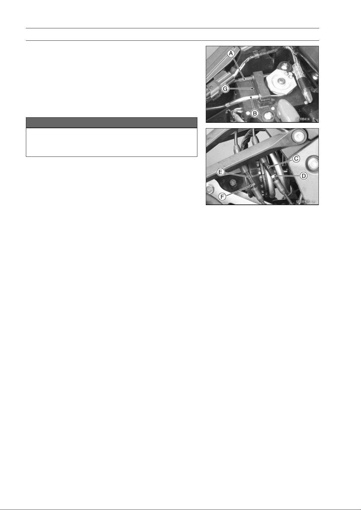
5-48 ENGINE TOP END
Muffler
•
Install the upper ends of the exhaust butterfly valve ca-
bles to the pulley of the exhaust butterfly valve actuator,
following the specified installing sequence.
○
First, install the close cable (black) [A].
○
Second, install the open cable (white) [B].
○
Third, stretch the open cable (white) by using the adjuster
[C].
○
Turn the adjuster counterclockwise until the play of the
open cable becomes no play.
NOTICE
To keep the correct exhaust butterfly valve position,
be sure to adjust the open cable first. Do not over-
stretch the cable.
○
Fourth, tighten the adjuster locknut (white) [D] of the open
cable securely.
○
Fifth, stretch the close cable (black) by using the adjuster
[E].
○
Turn the adjuster counterclockwise until the play of the
close cable becomes no play.
○
Sixth, turn the adjuster of the close cable (black) clock-
wise by 1/2 to 1 rotation.
○
Seventh, tighten the adjuster locknut (black) [F] of the
close cable securely.
•
After installation, cover the dust covers on the adjusters.
•
Fix the exhaust butterfly valve cables with the clamps [G].
•
Run the exhaust butterfly cables into the holder clamps,
and install the holder clamps.
•
After connecting the cables, turn the ignition switch ON
and make sure that the pulley turns clockwise and coun-
terclockwise, then it returns clockwise slightly.

CLUTCH 6-1
6
Clutch
Table of Contents
Exploded View........................................................................................................................ 6-2
Specifications ......................................................................................................................... 6-4
Special Tool and Sealant........................................................................................................ 6-5
Clutch Lever and Cable.......................................................................................................... 6-6
Clutch Lever Free Play Inspection.................................................................................... 6-6
Clutch Lever Free Play Adjustment .................................................................................. 6-6
Clutch Cable Removal ...................................................................................................... 6-6
Clutch Cable Installation ................................................................................................... 6-6
Clutch Cable Lubrication................................................................................................... 6-6
Clutch Lever Assembly Installation................................................................................... 6-6
Clutch Cover........................................................................................................................... 6-7
Clutch Cover Removal...................................................................................................... 6-7
Clutch Cover Installation................................................................................................... 6-7
Release Shaft Removal .................................................................................................... 6-7
Release Shaft Installation ................................................................................................. 6-7
Clutch Cover Disassembly................................................................................................ 6-8
Clutch Cover Assembly..................................................................................................... 6-8
Clutch ..................................................................................................................................... 6-10
Clutch Removal................................................................................................................. 6-10
Clutch Installation..............................................................................................................6-10
Clutch Plate Assembly Inspection..................................................................................... 6-13
Clutch Plate Assembly Adjustment................................................................................... 6-13
Clutch Plate, Wear, Damage Inspection ........................................................................... 6-14
Clutch Plate Warp Inspection............................................................................................ 6-14
Clutch Spring Free Length Measurement......................................................................... 6-14
Clutch Housing Finger Inspection..................................................................................... 6-14
Clutch Housing Spline Inspection ..................................................................................... 6-14
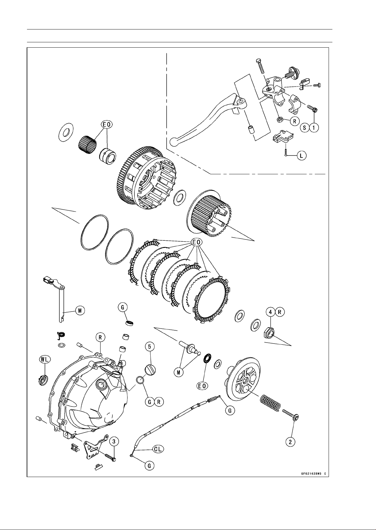
6-2 CLUTCH
Exploded View

CLUTCH 6-3
Exploded View
Torque
No. Fastener
N·m
kgf·m ft·lb
Remarks
1
Clutch Lever Assembly Clamp Bolts
7.8 0.80 69 in·lb
S
2 Clutch Spring Bolts 8.8 0.90 78 in·lb
3 Clutch Cover Bolts 9.8 1.0 87 in·lb
4 Clutch Hub Nut 135 13.8 99.6 R
5 Oil Filler Plug 2.0 0.20 18 in·lb
CL: Apply cable lubricant.
EO: Apply engine oil.
G: Apply grease.
L: Apply a non-permanent locking agent.
M: Apply molybdenum disulfide grease.
R: Replacement Parts
S: Follow the specified tightening sequence.
WL: Apply soap and water solution or rubber lubricant.

6-4 CLUTCH
Specifications
Item Standard Service Limit
Clutch Lever Free Play 2 ∼ 3 mm (0.08 ∼ 0.12 in.)
–––
Clutch
Clutch Plate Assembly Length 51.1 ∼ 51.7 mm (2.01 ∼ 2.04 in.) –––
Friction Plate Thickness 2.72 ∼ 2.88 mm (0.107 ∼ 0.113 in.) 2.4 mm (0.094 in.)
Friction and Steel Plate Warp 0.15 mm (0.0059 in.) or less 0.3 mm (0.012 in.)
Clutch Spring Free Length 64.8 mm (2.55 in.) 61.8 mm (2.43 in.)
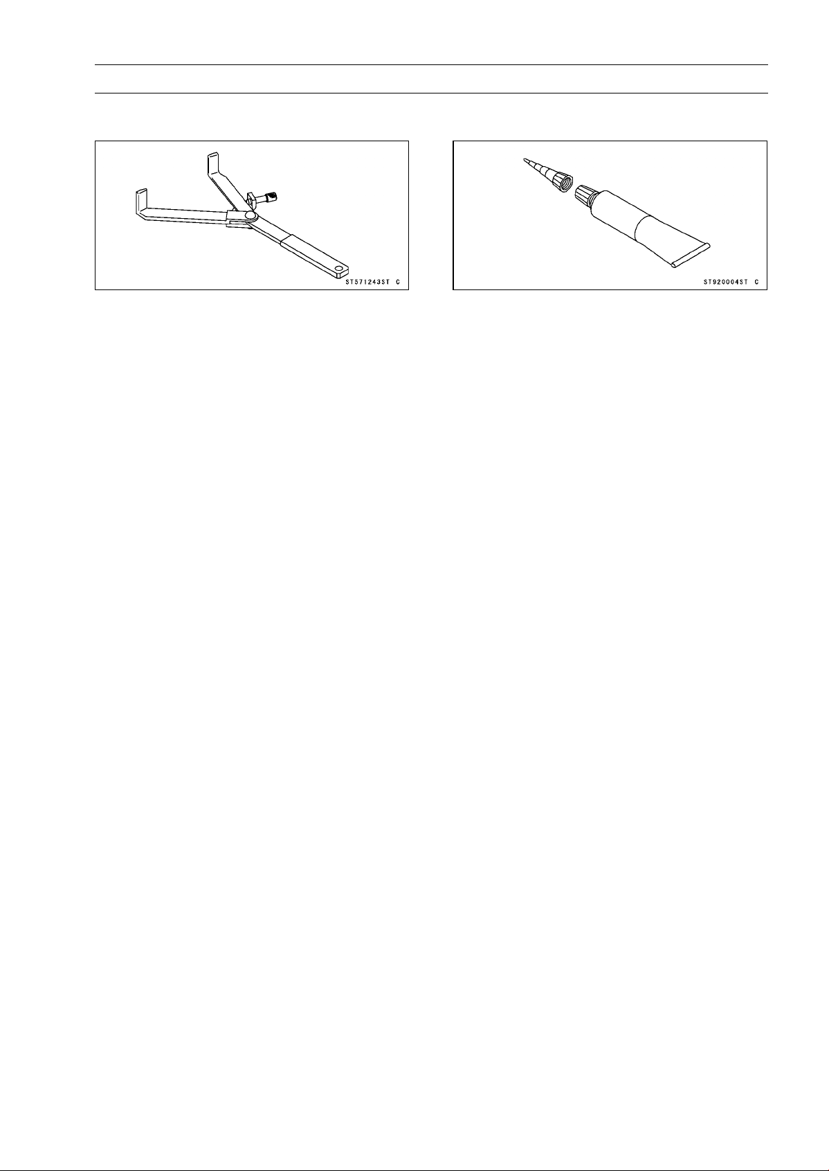
CLUTCH 6-5
SpecialToolandSealant
Clutch Holder:
57001-1243
Liquid Gasket, TB1211F:
92104-0004
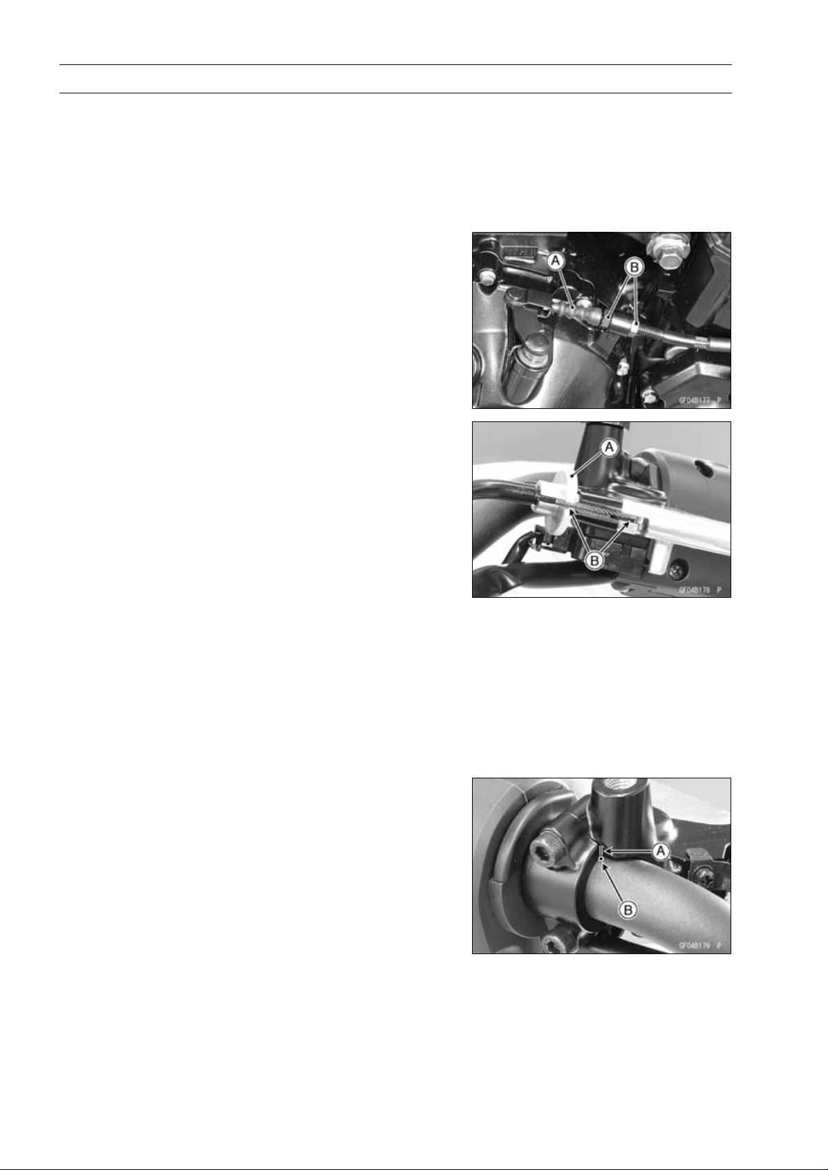
6-6 CLUTCH
Clutch Lever and Cable
Clutch Lever Free Play Inspection
•
Refer to the Clutch Operation Inspection in the Periodic
Maintenance chapter.
Clutch Lever Free Play Adjustment
•
Refer to the Clutch Operation Inspection in the Periodic
Maintenance chapter.
Clutch Cable Removal
•
Slide the dust cover [A] at the clutch cable lower end out
of place.
•
Loosen the nuts [B], and slide the lower end of the clutch
cable to give the cable plenty of play.
•
Screw in the adjuster [A].
•
Line up the slots [B] in the clutch lever and adjuster, and
then free the cable from the lever.
•
Free the clutch inner cable tip from the clutch release
lever.
•
Pull the clutch cable out of the frame.
Clutch Cable Installation
•
Run the clutch cable correctly (see Cable, Wire, and Hose
Routing section in the Appendix chapter).
•
Adjust the clutch cable (see Clutch Operation Inspection
in the Periodic Maintenance chapter).
Clutch Cable Lubrication
•
Refer to the Chassis Parts Lubrication in the Periodic
Maintenance chapter.
Clutch Lever Assembly Installation
•
Install the clutch lever so that the mating surface [A] of the
clutch lever clamp is aligned with the punch mark [B].
•
Tighten the upper clamp bolt first, and then the lower
clamp bolt. There will be a gap at the lower part of the
clamp after tightening.
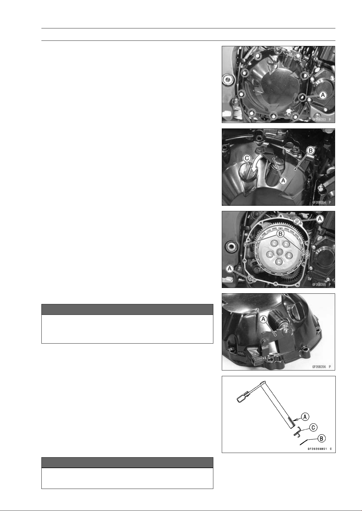
CLUTCH 6-7
Clutch Cover
Clutch Cover Removal
•
Remove:
Rear Lower Fairing (see Rear Lower Fairing Removal in
the Frame chapter)
Engine Oil (Drain, see Engine Oil Change in the Periodic
Maintenance chapter)
Clutch Cable Lower End
Clutch Cover Mounting Bolts [A]
•
Turn the release lever [A] toward the rear as shown in the
figure, and remove the clutch cover [B].
About 90° [C]
Clutch Cover Installation
•
Be sure to dowel pins [A].
•
Apply silicone sealant to the area [B] where the mating
surface of the crankcase touches the clutch cover gasket.
Sealant - Liquid Gasket, TB1211F: 92104-0004
•
Replace the clutch cover gasket with a new one and install
it.
•
Tighten:
Torque - Clutch Cover Bolts: 9.8 N·m (1.0 kgf·m, 87 in·lb)
Release Shaft Removal
NOTICE
Do not remove the clutch release lever and shaft
assembly unless it is absolutely necessary. If re-
moved, the oil seal replacement may be required.
•
Remove the clutch cover (see Clutch Cover Removal).
•
Pull the release lever and shaft assembly [A] straight out
of the clutch cover.
Release Shaft Installation
•
Apply grease to the oil seal lips on the upper ridge of the
clutch cover.
•
Apply engine oil to the needle bearings in the hole of the
clutch cover.
•
Apply molybdenum disulfide grease to the pusher-holding
portion [A] on the release shaft.
•
Install the washer [B] and spring [C].
•
Insert the release shaft straight into the upper hole of the
clutch cover.
NOTICE
When inserting the release shaft, be careful not to
remove the spring of the oil seal.
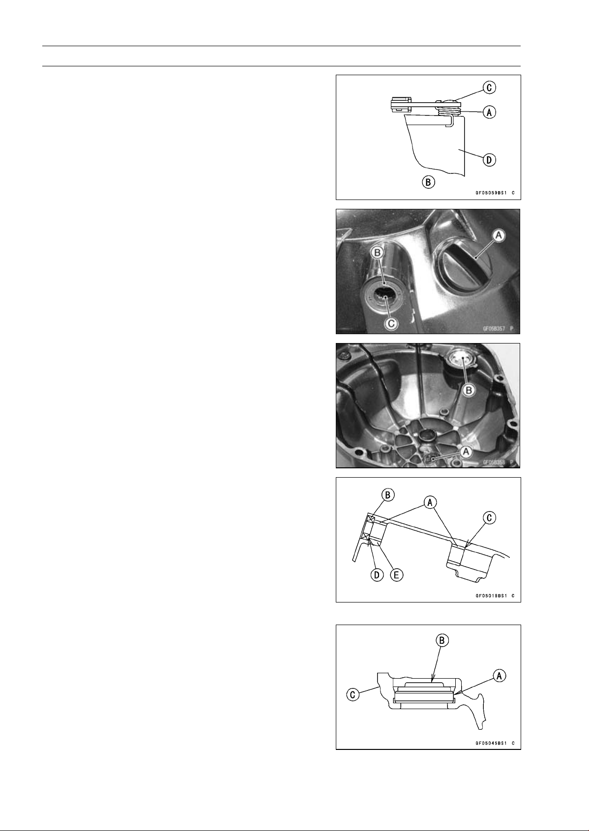
6-8 CLUTCH
Clutch Cover
•
Fit the spring [A] as shown in the figure.
Viewed from Rear [B]
Release Shaft [C]
Clutch Cover [D]
Clutch Cover Disassembly
•
Remove:
Clutch Cover (see Clutch Cover Removal)
Release Lever and Shaft Assembly (see Release Shaft
Removal)
Oil Filler Plug [A]
Oil Seal [B]
Needle Bearing [C]
•
Remove:
Needle Bearing [A]
Oil Level Gauge [B]
Clutch Cover Assembly
•
Replace the needle bearings and oil seal with new ones.
NOTE
○
Install the needle bearings so that the manufacture’s
mark face out.
•
Install the needle bearings [A] and oil seal [B] position as
shown in the figure.
Press the needle bearing until the bottom [C].
Press the needle bearings so that the bearing surface
[D] is flush with the housing end of clutch cover [E].
•
Apply water to the rubber portion [A] of the oil level gauge.
•
Press the gauge until the bottom so that its projection [B]
faces inside of the clutch cover [C].

CLUTCH 6-9
Clutch Cover
•
Replace the O-ring [A] of the oil filler plug [B] with a new
one.
•
Apply grease to the O-ring.
•
Tighten:
Torque - Oil Filler Plug: 2.0 N·m (0.20 kgf·m, 18 in·lb)
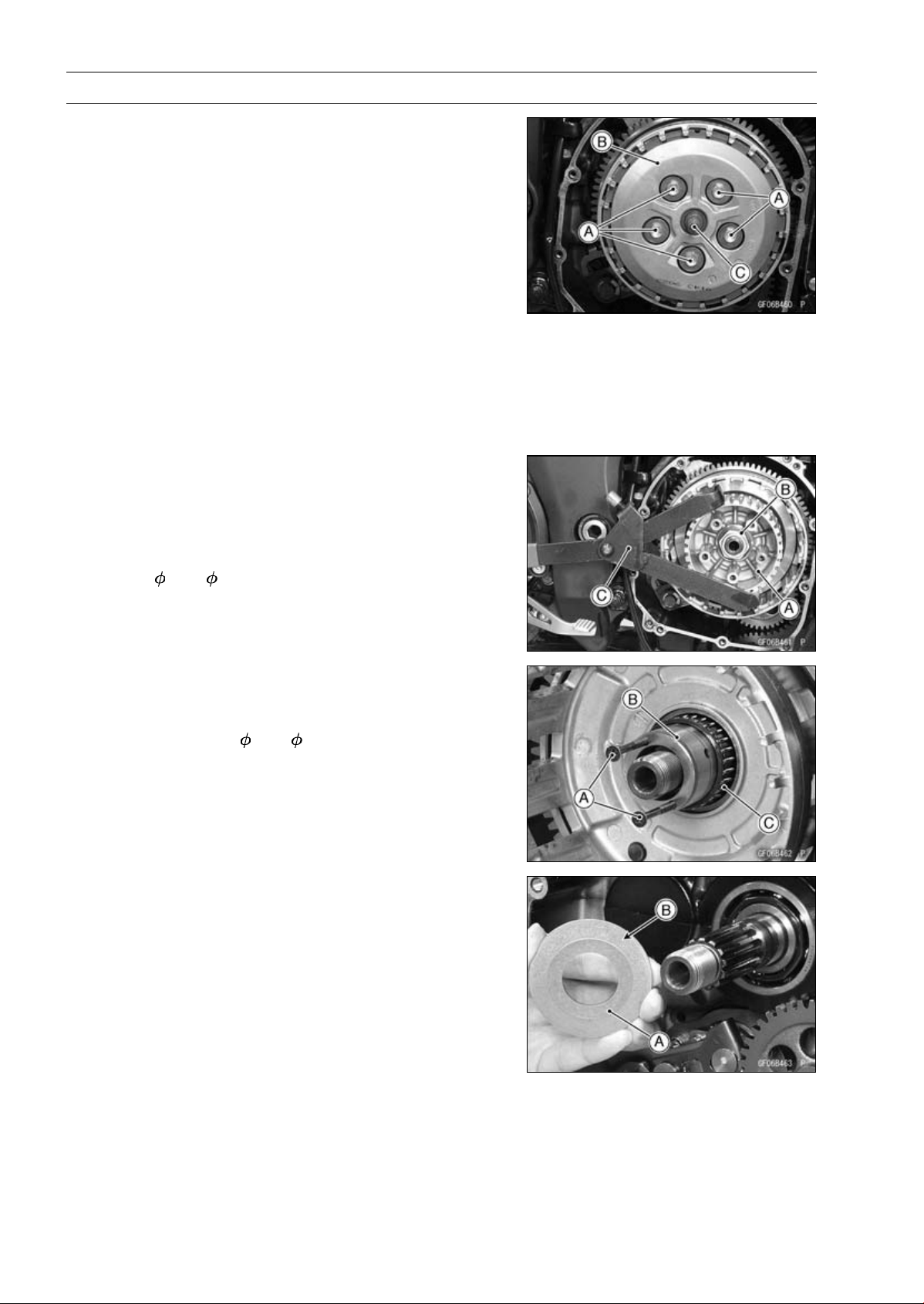
6-10 CLUTCH
Clutch
Clutch Removal
•
Remove:
Clutch Cover (see Clutch Cover Removal)
Clutch Spring Bolts [A]
Clutch Springs
Clutch Spring Plate [B] (with Washer, Needle Bearing
and Pusher [C])
•
Remove:
Friction Plates and Steel Plates
Spring and Spring Seat
NOTE
○
The two plates at both ends are different from the plate
installed between these plates.
However, it is impossible to identify it on externals.
○
Mark and record the locations of the friction plates so
that they can be reinstalled in their original positions.
•
Holding the clutch hub [A], remove the nut [B] and wash-
ers.
Special Tool - Clutch Holder [C]: 57001-1243
•
Remove:
Clutch Hub
Spacer (
47 × 25.5)
•
Using the two M4 bolts or screws [A], pull out the sleeve
[B], and then remove the needle bearing [C] and clutch
housing.
•
Remove the spacer (
56 × 25).
Clutch Installation
•
Install the spacer [A] so that the tapered side [B] faces
inward.
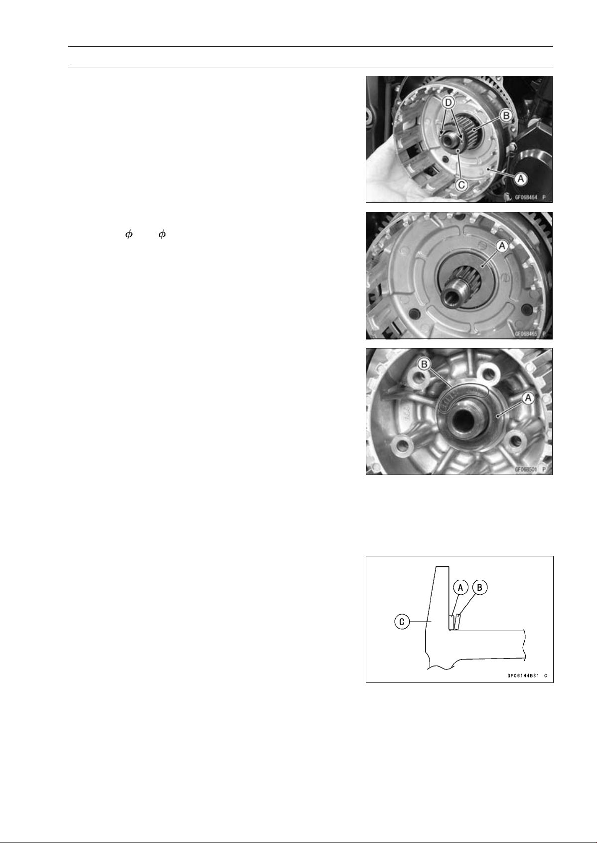
CLUTCH 6-11
Clutch
•
Install the clutch housing [A] to the drive shaft.
•
While holding the clutch housing, install the needle bear-
ing [B] and sleeve [C].
○
The holes [D] of the sleeve face outward.
•
Install the following parts to the drive shaft.
Spacer (
47 × 25.5) [A]
Clutch Hub
•
Install the washer [A] so that the “OUTSIDE” mark [B]
faces outward.
•
Replace the clutch hub nut with a new one.
•
Holding the clutch hub, tighten the clutch hub nut.
Special Tool - Clutch Holder: 57001-1243
Torque - Clutch Hub Nut: 135 N·m (13.8 kgf·m, 99.6 ft·lb)
•
Install the spring seat [A] and spring [B] as shown in the
figure.
Clutch Hub [C]
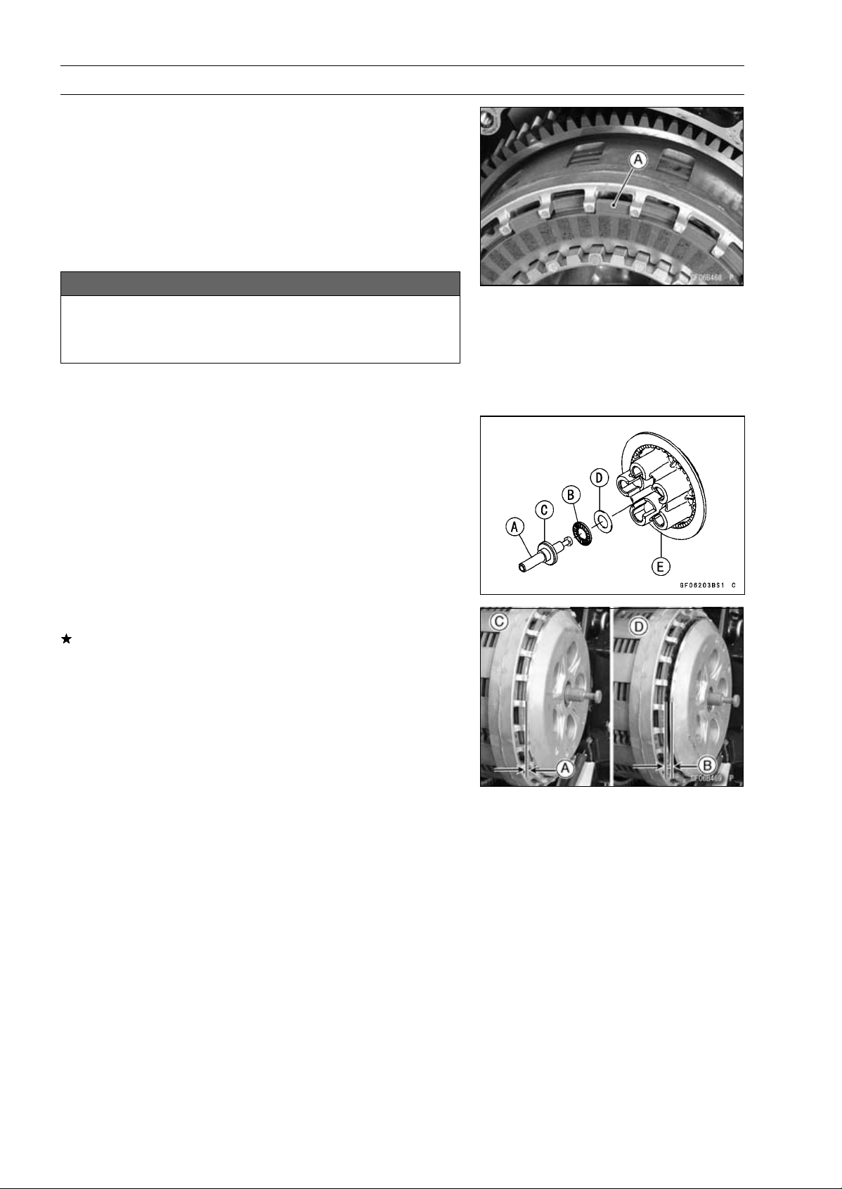
6-12 CLUTCH
Clutch
•
Install the friction plates and steel plates, starting with a
friction plate and alternating them.
NOTE
○
Install the both ends marked two friction plates at dis-
assembled to the their original position.
○
When replace the friction plates with new ones, mark
the both end two friction plates so that the two kinds of
friction plates do not mix up at opening the package.
NOTICE
If new dry friction plates and steel plates are in-
stalled, apply engine oil to the surfaces of each
plate to avoid clutch plate seizure.
○
Install the last friction plate [A] fitting the tangs in the
grooves in the housing as shown in the figure.
•
Apply molybdenum disulfide grease to the pusher shaft
[A].
•
Apply engine oil to the needle bearing [B].
•
Install the pusher [C], needle bearing and washer [D] in
the clutch spring plate [E].
•
Install the clutch spring plate so that there are no gap [A].
If it has gap [B], turn the clutch spring plate to install it
again.
[C] Correct
[D] Wrong
•
Install:
Clutch Springs
•
Tighten:
Torque - Clutch Spring Bolts: 8.8 N·m (0.90 kgf·m, 78 in·lb)
•
Install the clutch cover (see Clutch Cover Installation).

CLUTCH 6-13
Clutch
Clutch Plate Assembly Inspection
•
Inspect the friction plate thickness (see Clutch Plate,
Wear, Damage Inspection).
•
Measure the length [A] of the clutch plate assembly as
shown in the figure.
○
Assemble:
Clutch Hub [B]
Spring Seat [C]
Spring [D]
Friction Plates [E]
Steel Plates [F]
Clutch Spring Plate [G]
Clutch Springs [H]
Clutch Spring Bolts [I]
NOTE
○
Install the both ends marked two friction plates at dis-
assembled to the their original position.
Torque - Clutch Spring Bolts: 8.8 N·m (0.90 kgf·m, 78 in·lb)
Clutch Plate Assembly Length
Standard: 51.1
∼ 51.7 mm (2.01 ∼ 2.04 in.)
If the length is not within the specified range, adjust the
length (see Clutch Plate Assembly Adjustment).
Clutch Plate Assembly Adjustment
•
Inspect the clutch plate assembly length, and then re-
place the steel plate(s) which brings the length within the
specified range.
•
Remove:
Clutch Spring Bolts
Clutch Springs
Clutch Spring Plate
•
Replace the following steel plate(s).
Thickness Part Number
2.3 mm (0.091 in.) 13089-0008
2.6 mm (0.102 in.) 13089-0009
2.9 mm (0.114 in.) 13089-1093
NOTE
○
Do not use the steel plate of 2.3 mm (0.091 in.) and 2.9
mm (0.114 in.) thickness at the same time.
•
Install the removed parts, and inspect the clutch plate as-
sembly length.
Torque - Clutch Spring Bolts: 8.8 N·m (0.90 kgf·m, 78 in·lb)
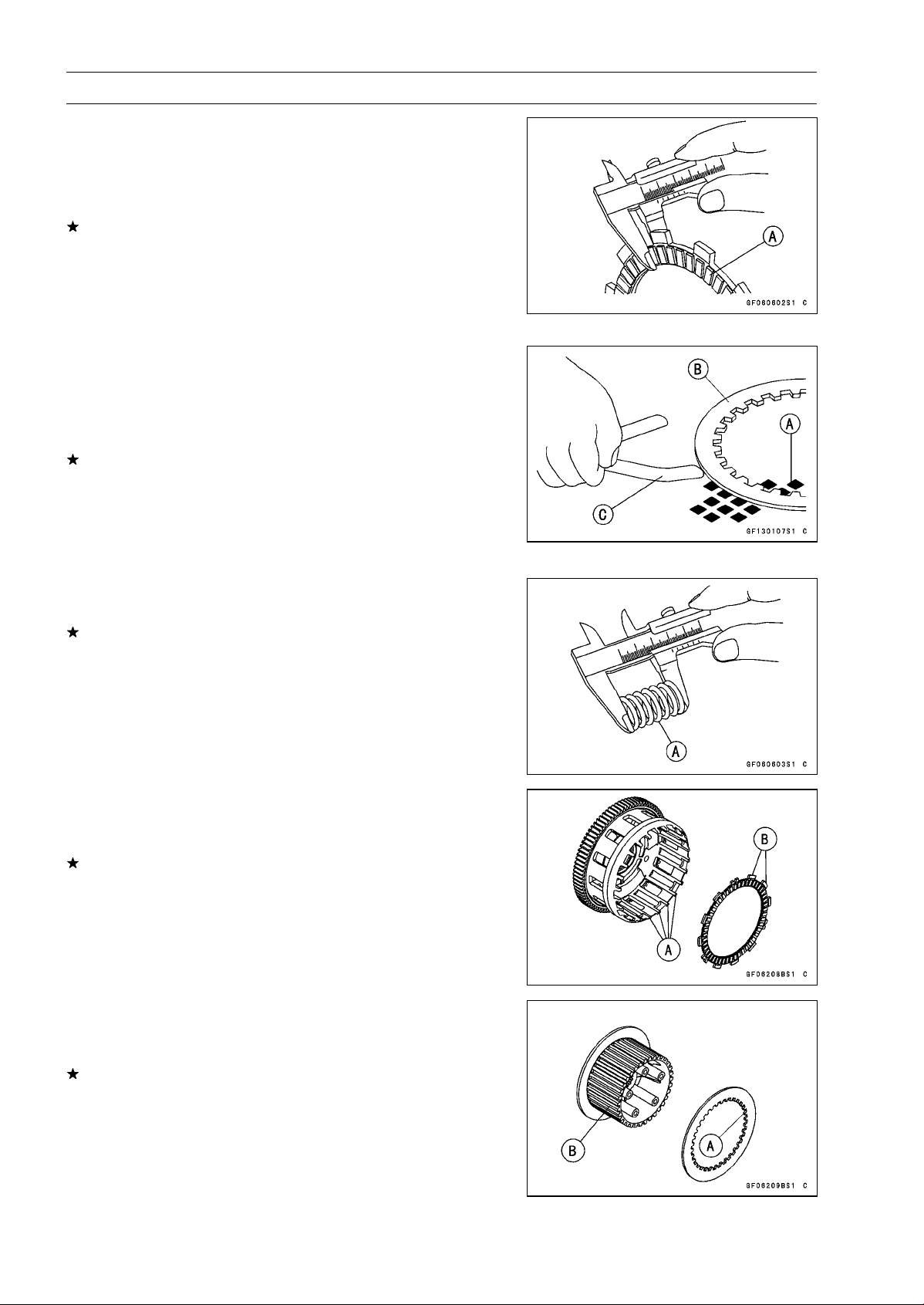
6-14 CLUTCH
Clutch
Clutch Plate, Wear, Damage Inspection
•
Visually inspect the friction and steel plates for signs of
seizure, overheating (discoloration), or uneven wear.
•
Measure the thickness of each friction plate [A] at several
points.
If any plates show signs of damage, or if they have worn
past the service limit, replace them with new ones.
Friction Plate Thickness
Standard: 2.72
∼ 2.88 mm (0.107 ∼ 0.113 in.)
Service Limit: 2.4 mm (0.094 in.)
Clutch Plate Warp Inspection
•
Place each friction plate or steel plate on a surface plate
and measure the gap between the surface plate [A] and
each friction plate or steel plate [B] with a thickness gauge
[C]. The gap is the amount of friction or steel plate warp.
If any plate is warped over the service limit, replace it with
a new one.
Friction and Steel Plate Warp
Standard: 0.15 mm (0.0059 in.) or less
Service Limit: 0.3 mm (0.012 in.)
Clutch Spring Free Length Measurement
•
Measure the free length of the clutch springs [A].
If any spring is shorter than the service limit, it must be
replaced.
Clutch Spring Free Length
Standard: 64.8 mm (2.55 in.)
Service Limit: 61.8 mm (2.43 in.)
Clutch Housing Finger Inspection
•
Visually inspect the clutch housing fingers [A] where the
friction plate tangs [B] hit them.
If they are badly worn or if there are groove cuts where the
tangs hit, replace the housing. Also, replace the friction
plates if their tangs are damaged.
Clutch Housing Spline Inspection
•
Visually inspect where the teeth [A] on the steel plates
wear against the clutch hub splines [B].
If there are notches worn into the splines, replace the
clutch hub. Also, replace the steel plates if their teeth are
damaged.

ENGINE LUBRICATION SYSTEM 7-1
7
Engine Lubrication System
Table of Contents
Exploded View........................................................................................................................ 7-2
Engine Oil Flow Chart............................................................................................................. 7-4
Specifications ......................................................................................................................... 7-5
Special Tools and Sealants .................................................................................................... 7-6
Engine Oil and Oil Filter.......................................................................................................... 7-7
Oil Level Inspection........................................................................................................... 7-7
Engine Oil Change............................................................................................................ 7-7
Oil Filter Replacement ...................................................................................................... 7-7
Oil Pan.................................................................................................................................... 7-8
Oil Pan Removal............................................................................................................... 7-8
Oil Pan Installation............................................................................................................ 7-8
Oil Screen............................................................................................................................... 7-10
Oil Screen Removal .......................................................................................................... 7-10
Oil Screen Installation....................................................................................................... 7-10
Oil Screen Cleaning.......................................................................................................... 7-10
Oil Pressure Relief Valve........................................................................................................ 7-11
Oil Pressure Relief Valve Removal ................................................................................... 7-11
Oil Pressure Relief Valve Installation ................................................................................ 7-11
Oil Pressure Relief Valve Inspection................................................................................. 7-11
Oil Pump................................................................................................................................. 7-12
Oil Pump Removal............................................................................................................ 7-12
Oil Pump Installation......................................................................................................... 7-12
Oil Pump Drive Gear Removal.......................................................................................... 7-13
Oil Pump Drive Gear Installation....................................................................................... 7-13
Oil Cooler................................................................................................................................ 7-14
Oil Cooler Removal........................................................................................................... 7-14
Oil Cooler Installation........................................................................................................ 7-14
Oil Pressure Measurement..................................................................................................... 7-15
Oil Pressure Measurement ............................................................................................... 7-15
Oil Pressure Switch ................................................................................................................ 7-16
Oil Pressure Switch Removal ........................................................................................... 7-16
Oil Pressure Switch Installation ........................................................................................ 7-16
Oil Pipe................................................................................................................................... 7-17
Oil Pipe Removal .............................................................................................................. 7-17
Oil Pipe Installation ........................................................................................................... 7-17
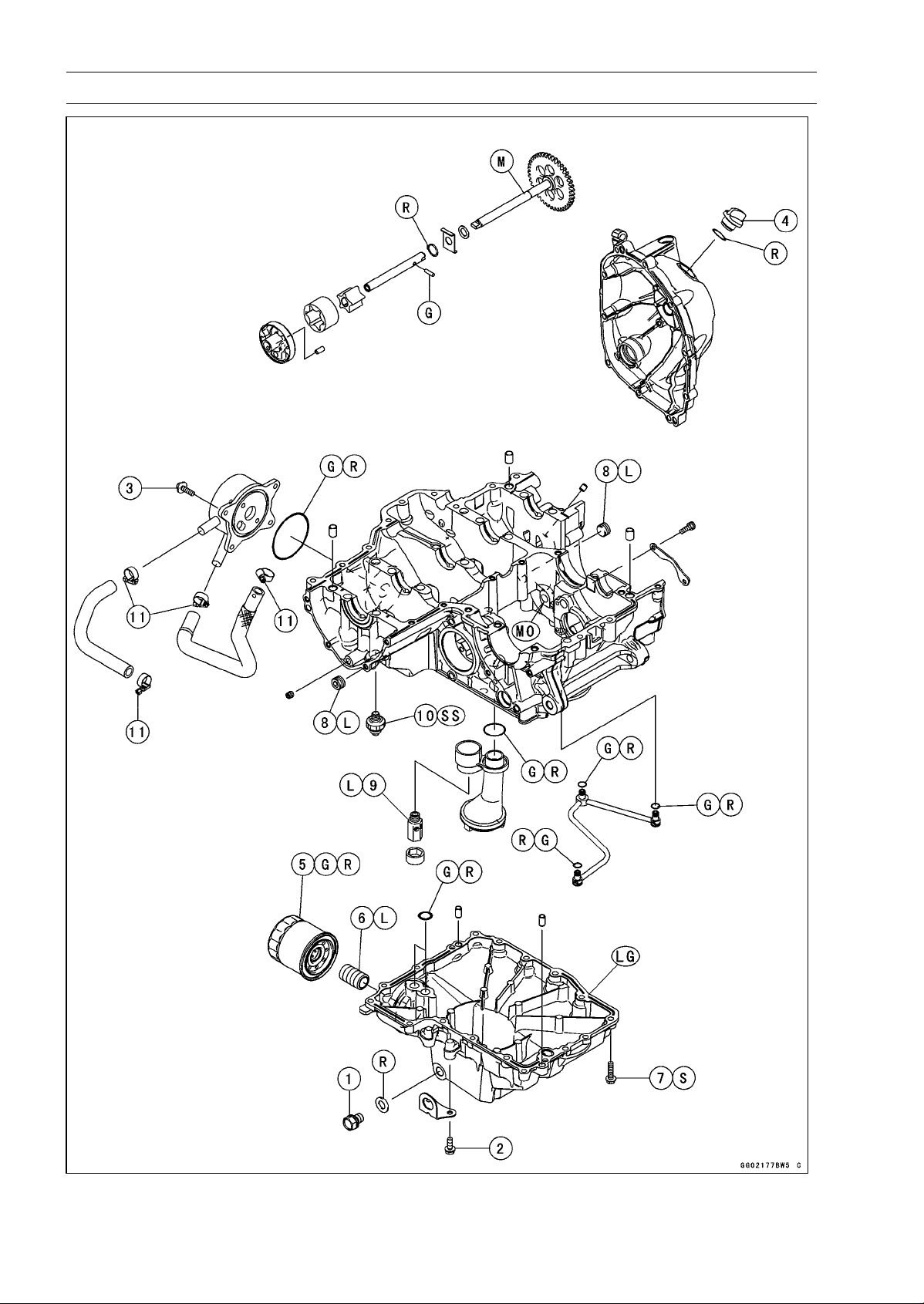
7-2 ENGINE LUBRICATION SYSTEM
Exploded View
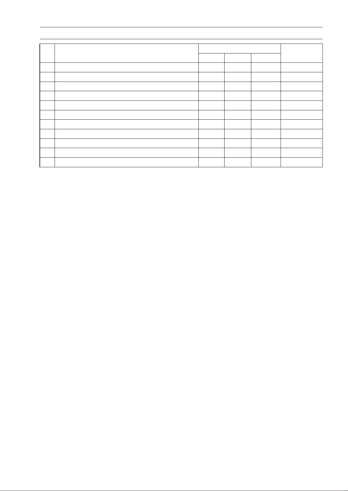
ENGINE LUBRICATION SYSTEM 7-3
Exploded View
Torque
No. Fastener
N·m
kgf·m ft·lb
Remarks
1
Engine Oil Drain Bolt
29 3.0 21
2 Lower Fairing Bracket Bolts 12 1.2 106 in·lb
3
Oil Cooler Bolts
12 1.2 106 in·lb
4
Oil Filler Plug
2.0 0.20 18 in·lb
5 Oil Filter 17 1.7 13 G, R
6 Oil Filter Pipe 25 2.5 18 L
7 Oil Pan Bolts 12 1.2 106 in·lb S
8 Oil Passage Plug 20 2.0 15 L
9
Oil Pressure Relief Valve
15 1.5 11 L
10
Oil Pressure Switch
15 1.5 11
SS
11 Radiator (Water) Hose Clamp Screws 3.0 0.31 27 in·lb
EO: Apply engine oil.
G: Apply grease.
L: Apply a non-permanent locking agent.
LG: Apply liquid gasket.
MO: Apply molybdenum disulfide oil solution.
(mixture of the engine oil and molybdenum disulfide grease in a weight ratio 10 : 1)
R: Replacement Parts
S: Follow the specified tightening sequence.
SS: Apply silicone sealant.
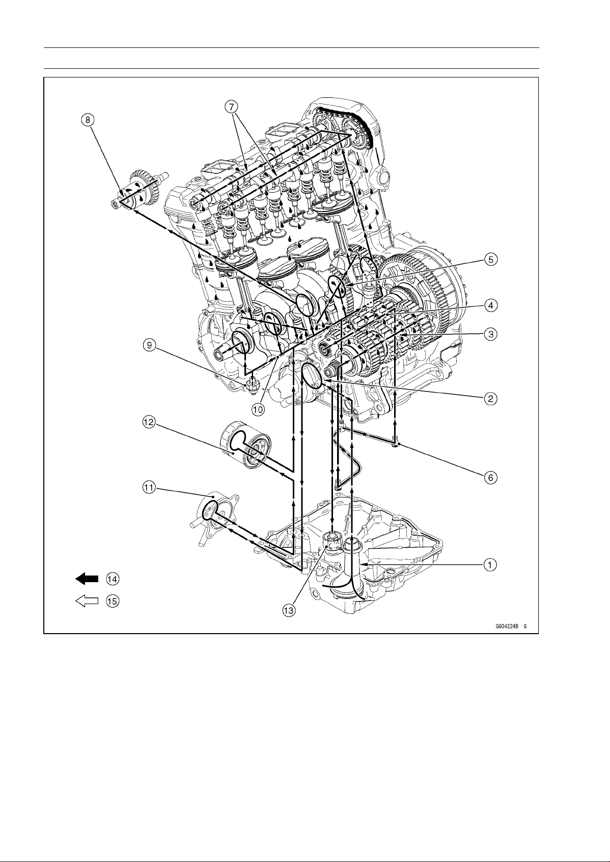
7-4 ENGINE LUBRICATION SYSTEM
Engine Oil Flow Chart
1. Oil Screen
2. Oil Pump
3. Output Shaft Oil Passage
4. Drive Shaft Oil Passage
5. Crankshaft Oil Passage
6. Oil Pipe
7. Camshaft Oil Passage
8. Balancer Oil Passage
9. Oil Pressure Switch
10. Main Oil Passage
11. Oil Cooler
12. Oil Filter
13. Oil Pressure Relief Valve
14. Oil
15. Blowby Gas
ENGINE LUBRICATION SYSTEM 7-5
Specifications
Item Standard
Engine Oil
Type
API SG, SH, SJ, SL or SM with JASO MA, MA1 or MA2
Viscosity
SAE 10W-40
Capacity: 3.2 L (3.4 US gt) (when filter is not removed)
3.8 L (4.0 US gt) (when filter is removed)
4.0 L (4.2 US gt) (when engine is completely dry)
Level Between upper and lower level lines (Wait several minutes after
idling or running)
Oil Pressure Measurement
Oil Pressure 255 ∼ 304 kPa (2.6 ∼ 3.1 kgf/cm², 37 ∼ 44 psi) at 4 000 r/min (rpm),
Oil Temperature 50°C (122°F)
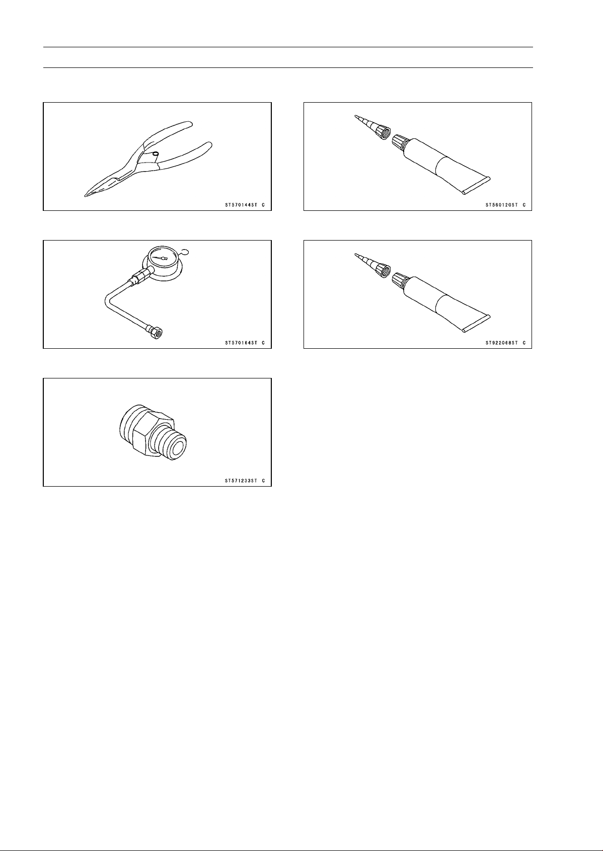
7-6 ENGINE LUBRICATION SYSTEM
Special Tools and Sealants
Outside Circlip Pliers:
57001-144
Oil Pressure Gauge, 10 kgf/cm²:
57001-164
Oil Pressure Gauge Adapter, PT3/8:
57001-1233
Liquid Gasket, TB1211:
56019-120
Liquid Gasket, TB1207B:
92104-2068

ENGINE LUBRICATION SYSTEM 7-7
Engine Oil and Oil Filter
WARNING
Vehicle operation with insufficient, deteriorated,
or contaminated engine oil will cause accelerated
wear and may result in engine seizure, accident,
and injury. Check the oil level before each use and
change the oil and filter according to the periodic
maintenance chart.
Oil Level Inspection
•
Check that the engine oil level is between the upper [A]
and lower [B] levels in the oil level inspection window.
NOTE
○
Situate the motorcycle so that it is perpendicular to the
ground.
○
If the motorcycle has just been used, wait several min-
utes for all the oil to drain down.
○
If the oil has just been changed, start the engine and
run it for several minutes at idle speed. This fills the oil
filter with oil. Stop the engine, then wait several minutes
until the oil settles.
NOTICE
Racing the engine before the oil reaches every part
can cause engine seizure.
If the engine oil gets extremely low or if the oil
pump or oil passages clog up or otherwise do not
function properly, the warning indicator light (LED)
and oil pressure warning symbol will blink. If this
blink stays on when the engine is running above
idle speed, stop the engine immediately and find
the cause.
If the oil level is too high, remove the excess oil, using a
syringe or some other suitable device.
If the oil level is too low, add the correct amount of oil
through the oil filler opening. Use the same type and
make of oil that is already in the engine.
NOTE
○
If the engine oil type and make are unknown, use any
brand of the specified oil to top off the level in preference
to running the engine with the oil level low. Then at your
earliest convenience, change the oil completely.
Engine Oil Change
•
Refer to the Engine Oil Change in the Periodic Mainte-
nance chapter.
Oil Filter Replacement
•
Refer to the Oil Filter Replacement in the Periodic Main-
tenance chapter.
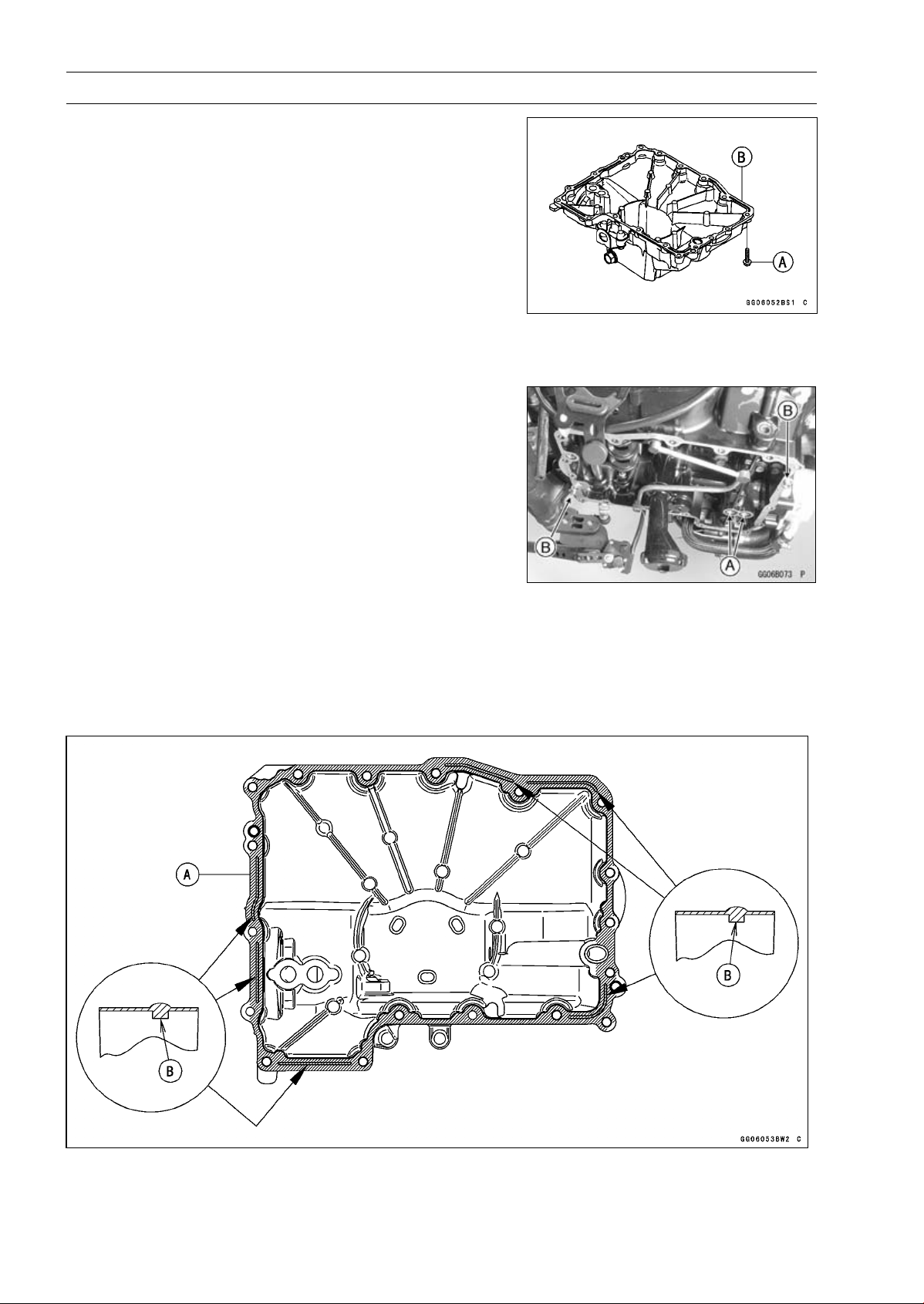
7-8 ENGINE LUBRICATION SYSTEM
Oil Pan
Oil Pan Removal
•
Remove:
Exhaust Pipe (see Exhaust Pipe Removal in the Engine
Top End chapter)
Oil Filter (see Oil Filter Replacement in the Periodic
Maintenance chapter)
Oil Pan Bolts [A]
Oil Pan [B]
•
Remove the following parts if necessary.
Oil Screen (see Oil Screen Removal)
OilPipe(seeOilPipeRemoval)
Oil Pressure Relief Valve (see Oil Pressure Relief Valve
Removal)
Oil Pan Installation
•
Install the following parts if removed.
Oil Pressure Relief Valve (see Oil Pressure Relief Valve
Installation)
Oil Pipe (see Oil Pipe Installation)
Oil Screen (see Oil Screen Installation)
•
Replace the O-rings [A] with new ones.
•
Apply grease to the O-rings, and install them.
•
Install the dowel pins [B].
•
Apply liquid gasket [A] to the mating surface of the oil pan.
Sealant - Liquid Gasket, TB1207B: 92104-2068
NOTE
○
Especially, apply liquid gasket so that it shall be filled up
on the grooves [B].
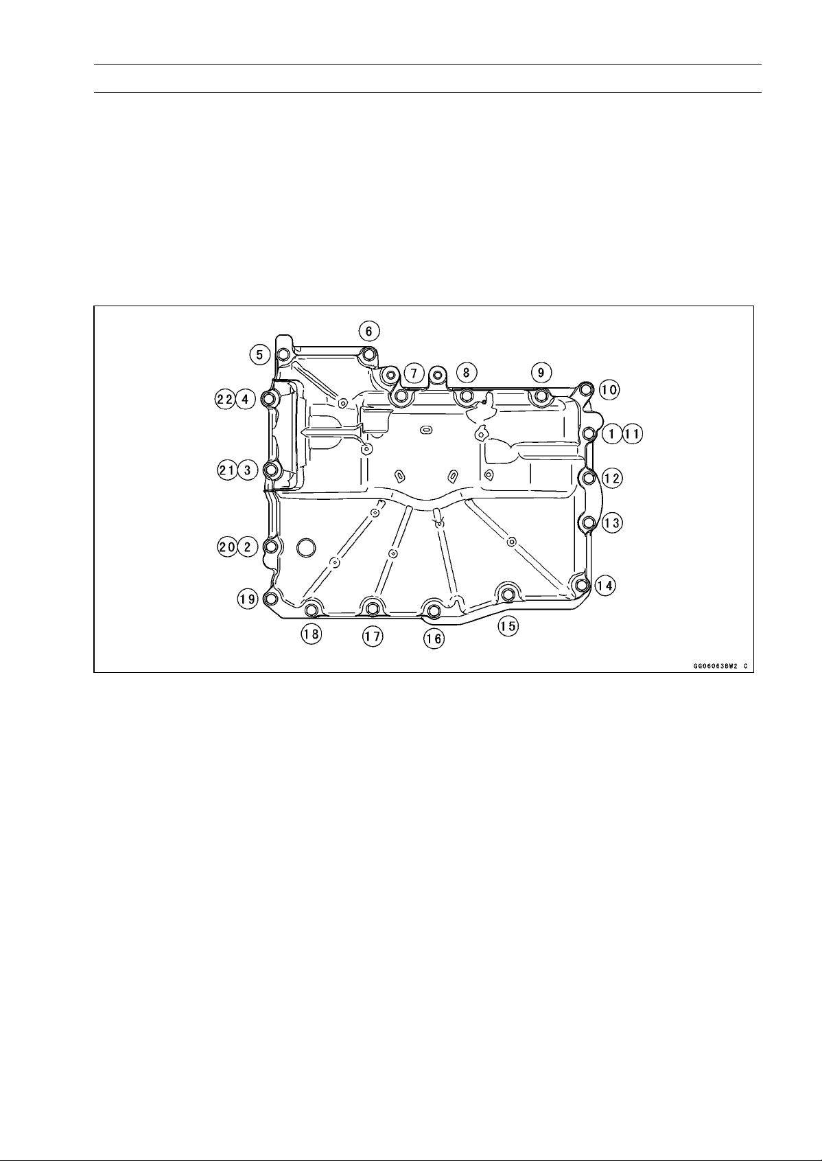
ENGINE LUBRICATION SYSTEM 7-9
Oil Pan
NOTE
○
Make the application finish within 7 minutes when the
liquid gasket to the mating surface of the oil pan is ap-
plied.
○
Moreover fit the oil pan and tighten the bolts just after
application of the liquid gasket.
•
Tighten the oil pan bolts following sequence [1 ∼ 22].
Torque - Oil Pan Bolts: 12 N·m (1.2 kgf·m, 106 in·lb)
Lower Fairing Bracket Bolts: 12 N·m (1.2 kgf·m,
106 in·lb)
•
Install the removed parts (see appropriate chapters).
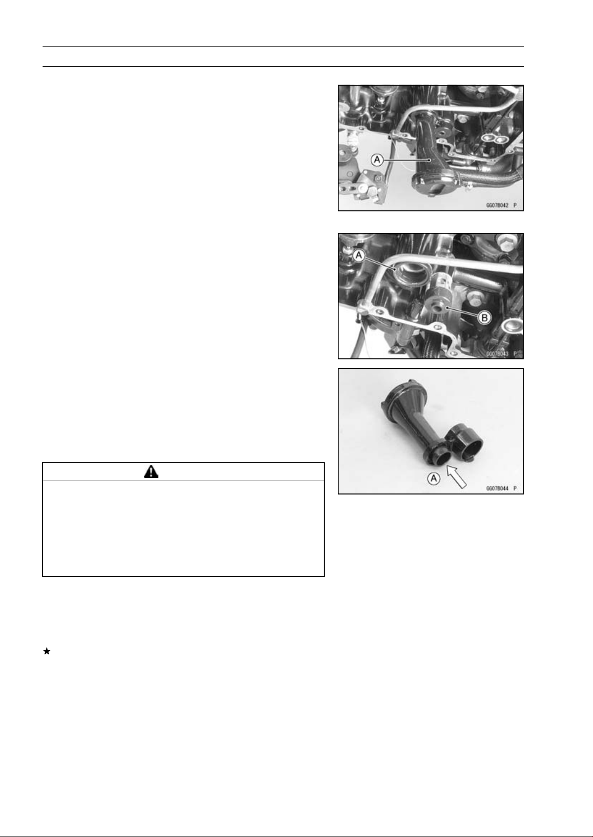
7-10 ENGINE LUBRICATION SYSTEM
Oil Screen
Oil Screen Removal
•
Remove:
Oil Pan (see Oil Pan Removal)
Oil Screen [A]
Oil Screen Installation
•
Clean the oil screen (see Oil Screen Cleaning).
•
Replace the O-ring [A] with a new one, and install it.
•
Apply grease to the O-ring.
•
Install the rubber damper [B] to the oil pressure relief
valve.
•
Install the oil screen.
Oil Screen Cleaning
•
Remove the oil screen (see Oil Screen Removal).
•
Clean the oil screen with a high flash-point solvent and
remove the particles stuck.
•
Blow away the particles by applying compressed air [A]
from the inside to the outside (from the clean side to the
dirty side).
WARNING
Gasoline and low flash-point solvents can be
flammable and/or explosive and cause severe
burns. Clean the screen in a well-ventilated area,
and take care that there are no sparks or flame
anywhere near the working area; this includes any
appliance with a pilot light. Do not use gasoline or
a low flash-point solvent to clean the screen.
NOTE
○
While cleaning the screen, check for any metal particles
that might indicate internal engine damage.
•
Check the screens carefully for any damage.
If the screen is damaged, replace the oil screen.
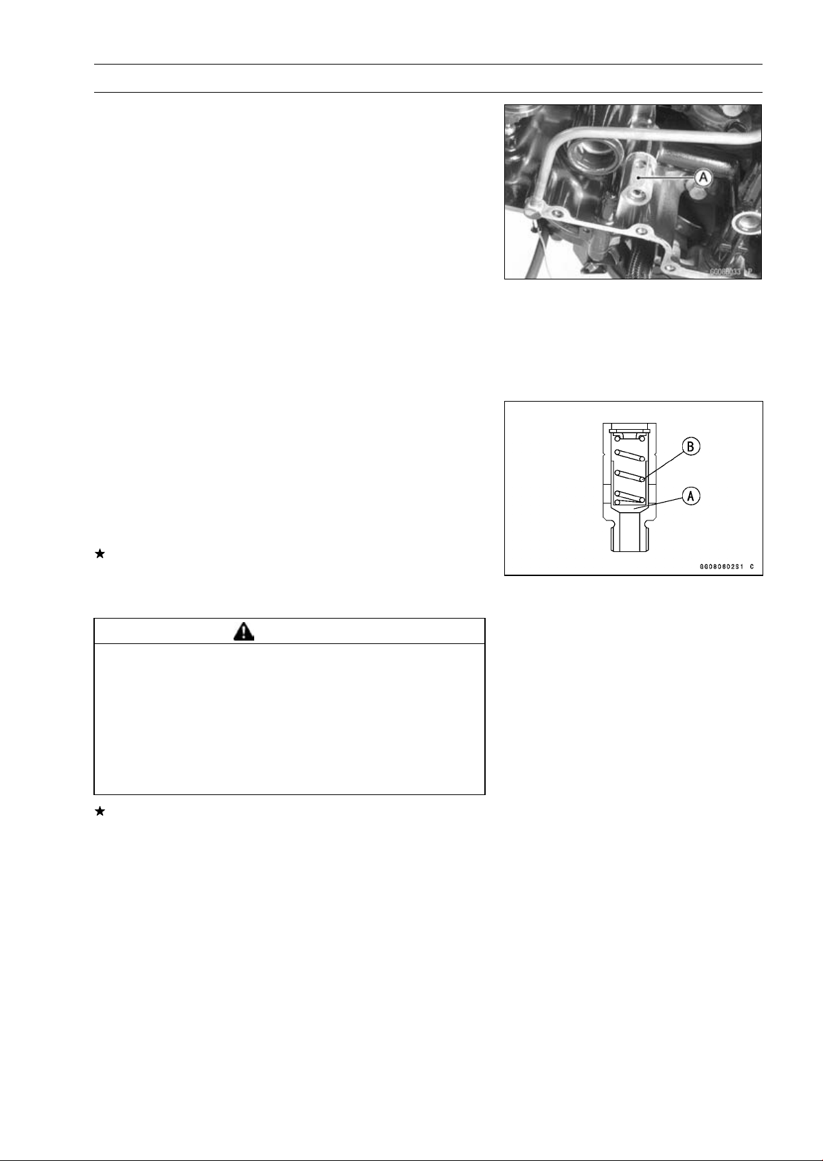
ENGINE LUBRICATION SYSTEM 7-11
Oil Pressure Relief Valve
Oil Pressure Relief Valve Removal
•
Remove:
Oil Screen (see Oil Screen Removal)
Oil Pressure Relief Valve [A]
Oil Pressure Relief Valve Installation
•
Apply a non-parmanent locking agent to the threads of
the oil pressure relief valve, and tighten it.
Torque - Oil Pressure Relief Valve: 15 N·m (1.5 kgf·m, 11
ft·lb)
Oil Pressure Relief Valve Inspection
•
Check to see if the valve [A] slides smoothly when push-
ing it in with a wooden or other soft rod, and see if it comes
back to its seat by spring [B] pressure.
NOTE
○
Inspect the valve in its assembled state. Disassembly
and assembly may change the valve performance.
If any rough spots are found during above inspection,
wash the valve clean with a high flash-point solvent and
blow out any foreign particles that may be in the valve with
compressed air.
WARNING
Gasoline and low flash-point solvents can be
flammable and/or explosive and cause severe
burns. Clean the oil pressure relief valve in a
well-ventilated area, and take care that there are no
sparks or flame anywhere near the working area;
this includes any appliance with a pilot light. Do
not use gasoline or a low flash-point solvent to
clean the oil pressure relief valve.
If cleaning does not solve the problem, replace the oil
pressure relief valve as an assembly. The oil pressure
relief valve is precision made with no allowance for re-
placement of individual parts.
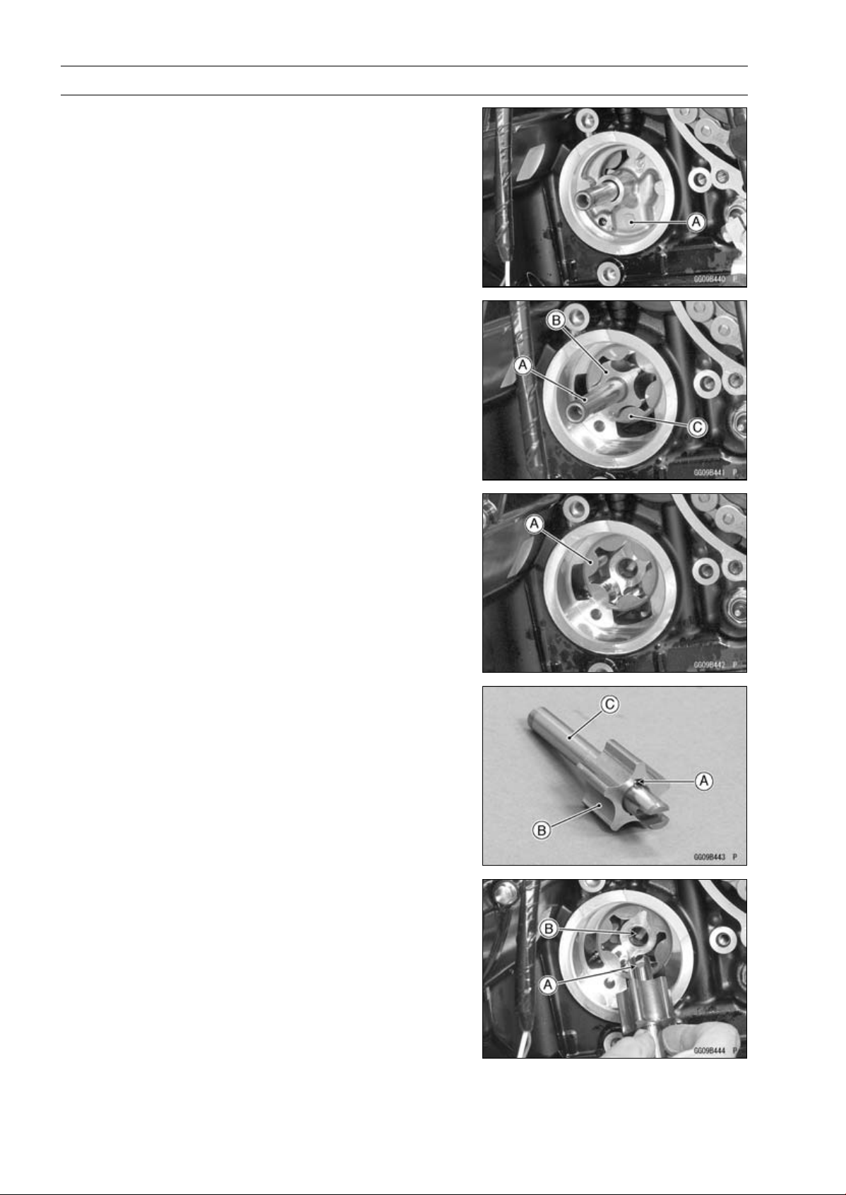
7-12 ENGINE LUBRICATION SYSTEM
Oil Pump
Oil Pump Removal
•
Remove:
Water Pump (see Water Pump Removal in the Cooling
System chapter)
Oil Pump Cover [A]
•
Remove:
Oil (Water) Pump Shaft [A] with Inner Rotor [B]
Outer Rotor [C]
Oil Pump Installation
•
Install the outer rotor [A] into the crankcase.
•
Apply grease to the pin [A].
•
Assemble the pin, inner rotor [B] and oil (water) pump
shaft [C].
•
Turn the pump shaft so that the slot [A] in its shaft fits onto
the projection [B] of the pump drive gear shaft.
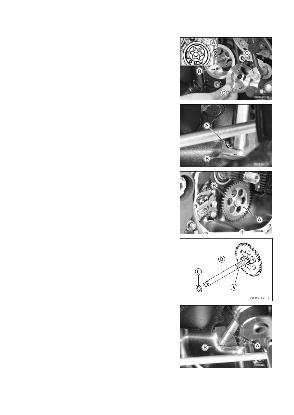
ENGINE LUBRICATION SYSTEM 7-13
Oil Pump
•
Pack grease into the cavity [A] between the inner rotor
and outer rotor for improve the oil pump initial priming.
•
Install the dowel pin [B].
•
Install the oil pump cover [C] so that the dowel pin fit into
the hole [D] of the oil pump cover.
•
Install the water pump (see Water Pump Installation in the
Cooling System chapter).
Oil Pump Drive Gear Removal
•
Remove:
Clutch (see Clutch Removal in the Clutch chapter)
Oil Pan (see Oil Pan Removal)
Circlip [A] and Washer [B]
Special Tool - Outside Circlip Pliers: 57001-144
•
Remove:
Oil Pump Drive Gear [A]
Washer [B]
Oil Pump Drive Gear Installation
•
Apply molybdenum disulfide grease to the journal portion
[A] on the oil pump drive gear shaft [B].
•
Install the washer [C] to the shaft.
•
Apply molybdenum disulfide oil solution to the insert holes
of the oil pump drive shaft.
•
Replace the circlip [A] with a new one.
•
Insert the oil pump drive gear to the lower crankcase.
•
Install the washer [B] and circlip.
Special Tool - Outside Circlip Pliers: 57001-144
•
Fit the projection on the shaft and oil (water) pump shaft
slot.
•
Set the circlip original position.
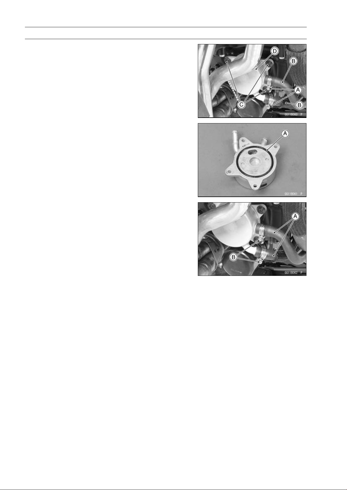
7-14 ENGINE LUBRICATION SYSTEM
Oil Cooler
Oil Cooler Removal
•
Remove:
Coolant (Drain, see Coolant Change in the Periodic
Maintenance chapter)
Engine Oil (Drain, see Engine Oil Change in the Periodic
Maintenance chapter)
Water Hose Clamp Screws (Loosen) [A]
Water Hoses [B]
Oil Cooler Bolts [C]
Oil Cooler [D]
Oil Cooler Installation
•
Replace the O-ring [A] with a new one.
•
Apply grease to the O-ring and install it.
•
Install the oil cooler.
•
Tighten:
Torque - Oil Cooler Bolts: 12 N·m (1.2 kgf·m, 106 in·lb)
•
Install the water hoses [A] and clamps as shown in the
figure.
•
Tighten:
Torque - Radiator (Water) Hose Clamp Screws [B]: 3.0 N·m
(0.31 kgf·m, 27 in·lb)
•
Install the removed parts (see appropriate chapters).
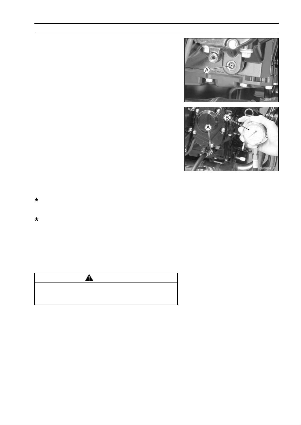
ENGINE LUBRICATION SYSTEM 7-15
Oil Pressure Measurement
Oil Pressure Measurement
•
Remove the right lower fairing (see Lower Fairing Re-
moval in the Frame chapter).
•
Remove the oil passage plug [A].
•
Aattach the adapter [A] and gauge [B] to the plug hole.
Special Tools - Oil Pressure Gauge, 10 kgf/cm²: 57001-164
Oil Pressure Gauge Adapter, PT3/8: 57001
-1233
•
Start the engine and warm up the engine.
•
Run the engine at the specified speed, and read the oil
pressure gauge.
If the oil pressure is much lower than the standard, check
the oil pump, relief valve, and/or crankshaft bearing insert
wear immediately.
If the reading is much higher than the standard, check the
oil passages for clogging.
Oil Pressure
Standard: 255
∼ 304 kPa (2.6 ∼ 3.1 kgf/cm², 37 ∼ 44
psi) at 4 000 r/min (rpm), oil temperature
50°C (122°F)
•
Stop the engine.
•
Remove the oil pressure gauge and adapter.
WARNING
Take care against burns form hot engine oil that
will drain through the oil passage when the gauge
adapter is removed.
•
Apply a non-permanent locking agent to the oil passage
plug, and tighten it.
Torque - Oil Passage Plug: 20 N·m (2.0 kgf·m, 15 ft·lb)
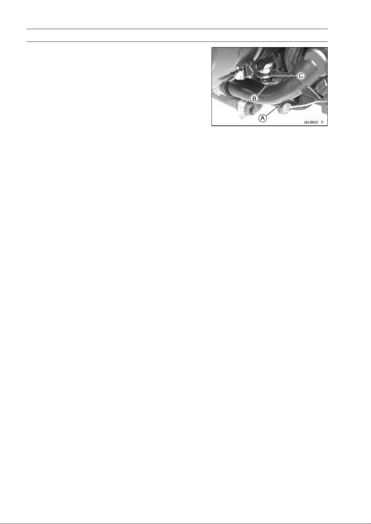
7-16 ENGINE LUBRICATION SYSTEM
Oil Pressure Switch
Oil Pressure Switch Removal
•
Remove:
Engine Oil (Drain, see Engine Oil Change in the Periodic
Maintenance chapter)
Switch Cover [A]
Switch Terminal Bolt [B]
OilPressureSwitch[C]
Oil Pressure Switch Installation
•
Apply silicone sealant to the threads of the oil pressure
switch and tighten it.
Sealant - Liquid Gasket, TB1211: 56019-120
Torque - Oil Pressure Switch: 15 N·m (1.5 kgf·m, 11 ft·lb)
•
Install the switch lead.
•
Tighten:
Torque - Oil Pressure Switch Terminal Bolt: 2.0 N·m (0.20
kgf·m, 18 in·lb)
•
Apply grease to the terminal.
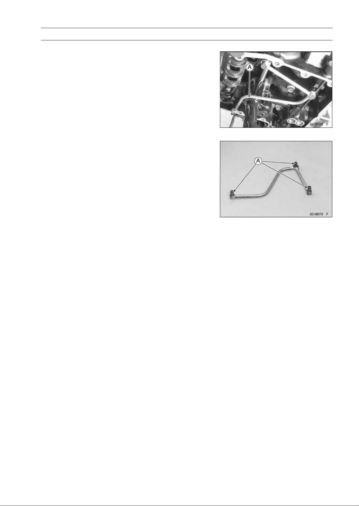
ENGINE LUBRICATION SYSTEM 7-17
Oil Pipe
Oil Pipe Removal
•
Remove:
Oil Pan (see Oil Pan Removal)
Oil Pipe [A]
Oil Pipe Installation
•
Replace the O-rings [A] with new ones.
•
Apply grease to the O-rings, and install them.


ENGINE REMOVAL/INSTALLATION 8-1
8
Engine Removal/Installation
Table of Contents
Exploded View........................................................................................................................ 8-2
Special Tool ............................................................................................................................ 8-4
Engine Removal/Installation................................................................................................... 8-5
Engine Removal................................................................................................................ 8-5
Engine Installation............................................................................................................. 8-8
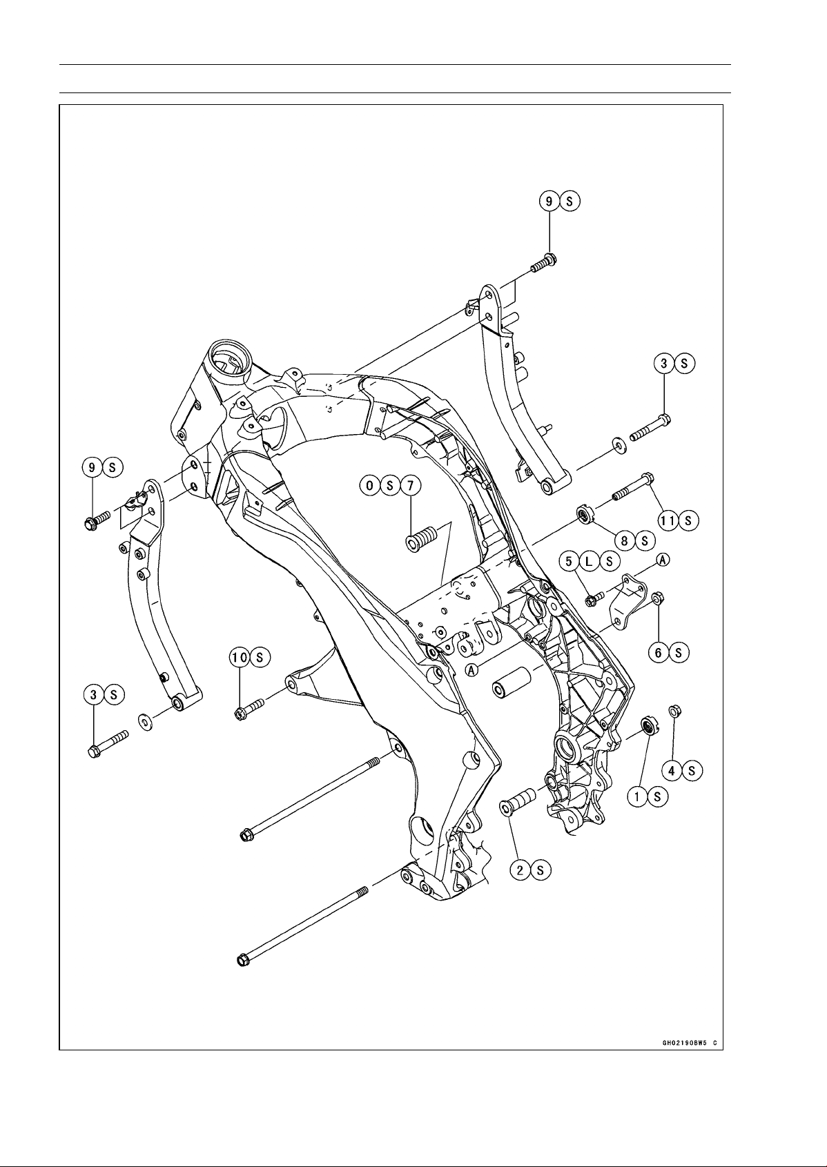
8-2 ENGINE REMOVAL/INSTALLATION
Exploded View
ENGINE REMOVAL/INSTALLATION 8-3
Exploded View
Torque
No. Fastener
N·m
kgf·m ft·lb
Remarks
1
Lower Adjusting Collar Locknut
49 5.0 36
S
2 Lower Adjusting Collar 9.8 1.0 87 in·lb S
3 Lower Engine Bracket Bolts 59 6.0 44 S
4 Lower Engine Mounting Nut 44 4.5 32 S
5 Middle Engine Bracket Bolts 25 2.5 18 L, S
6 Middle Engine Mounting Nut 44 4.5 32
S
7
Upper Adjusting Collar
5.0 0.51 44 in·lb
S
8 Upper Adjusting Collar Locknut 49 5.0 36 S
9 Upper Engine Bracket Bolts 44 4.5 32 S
10 Upper Engine Mounting Bolt (L = 40) 44 4.5 32 S
11 Upper Engine Mounting Bolt (L = 65) 44 4.5 32 S
L: Apply a non-permanent locking agent.
O: Apply 2-stroke oil.
S: Follow the specified tightening sequence.
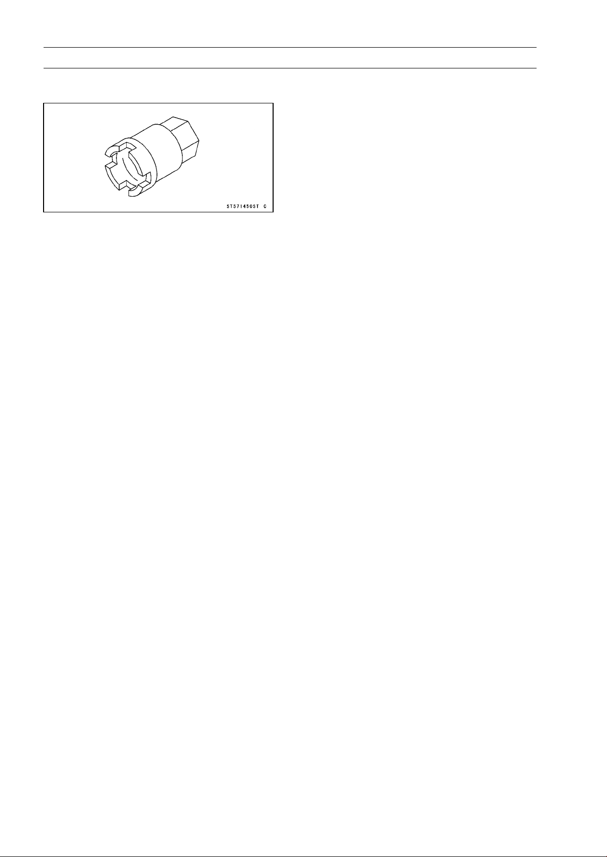
8-4 ENGINE REMOVAL/INSTALLATION
Special Tool
Engine Mount Nut Wrench:
57001-1450
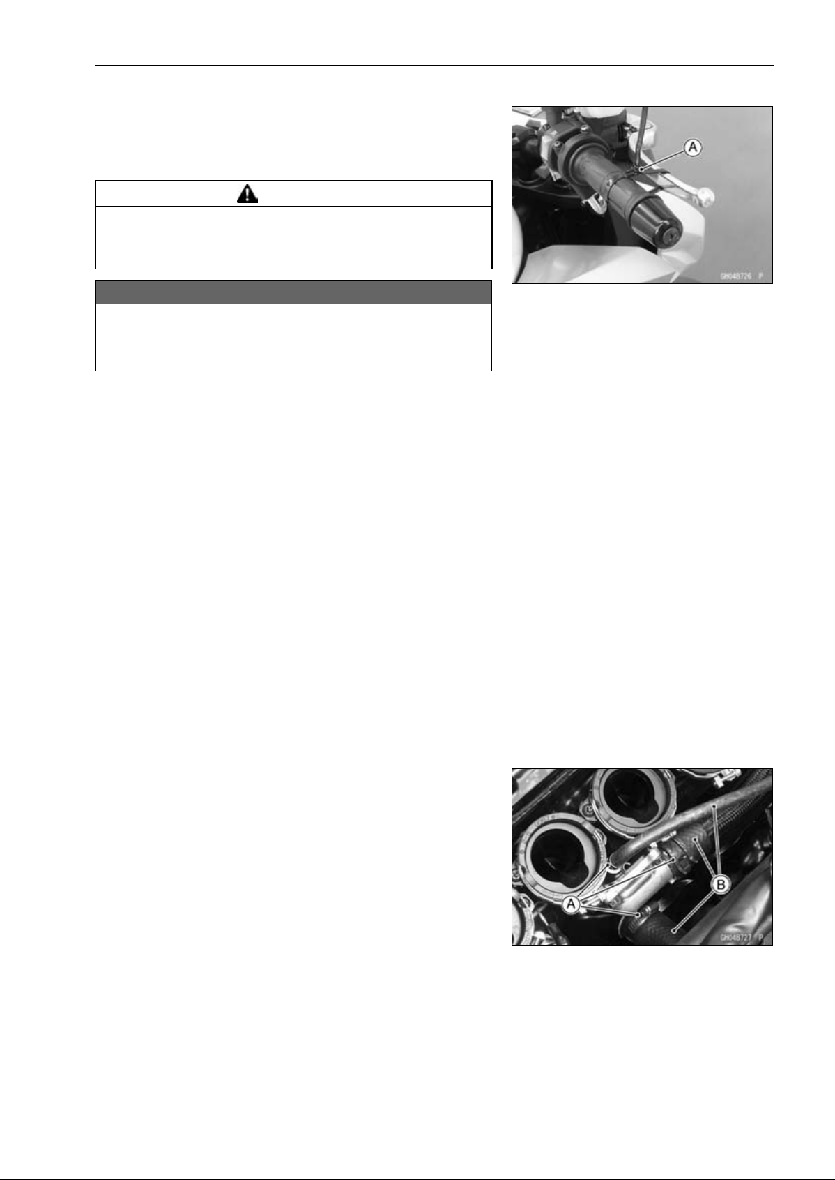
ENGINE REMOVAL/INSTALLATION 8-5
Engine Removal/Installation
Engine Removal
•
Support the rear part of the swingarm with a stand.
•
Squeeze the brake lever slowly and hold it with a band
[A].
WARNING
Motorcycle may fall over unexpectedly resulting in
an accident or injury. Be sure to hold the front brake
when removing the engine.
NOTICE
Be sure to hold the front brake when removing the
engine, or the motorcycle may fall over. The engine
or the motorcycle could be damaged.
•
Remove:
Engine Oil (Drain, see Engine Oil Change in the Periodic
Maintenance chapter)
Coolant (Drain, see Coolant Change in the Periodic
Maintenance chapter)
Center Fairings (see Center Fairing Removal in the
Frame chapter)
Clutch Cable Lower End (see Clutch Cable Removal in
the Clutch chapter)
Radiator (see Radiator and Radiator Fan Removal in the
Cooling System chapter)
Exhaust Pipe (see Exhaust Pipe Removal in the Engine
Top End chapter)
Air Switching Valve (see Air Switching Valve Removal in
the Engine Top End chapter)
Throttle Body Assy (see Throttle Body Assy Removal in
the Fuel System (DFI) chapter)
Shift Lever (see Shift Pedal Removal in the Crank-
shaft/Transmission chapter)
Engine Sprocket (see Engine Sprocket Removal in the
Final Drive chapter)
•
Remove:
Clamps [A]
Water Hoses [B]
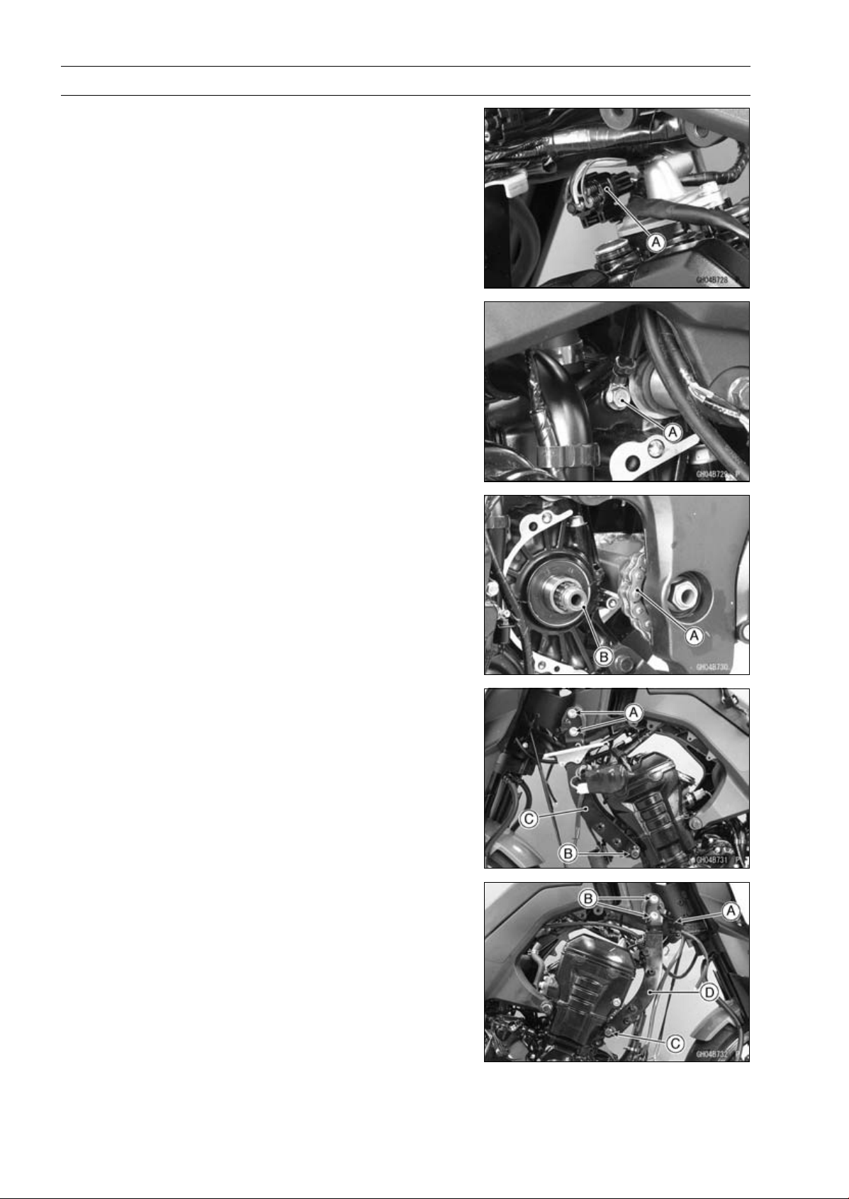
8-6 ENGINE REMOVAL/INSTALLATION
Engine Removal/Installation
•
Remove the connector [A] from the bracket on the air suc-
tion valve cover.
•
Disconnect the connector.
•
Disconnect:
Starter Motor Cable (see Starter Motor Removal in the
Electrical System chapter)
Alternator Lead Connector (see Alternator Cover Re-
moval in the Electrical System chapter)
Crankshaft Sensor Lead Connector (see Crankshaft
Sensor Removal in the Electrical System chapter)
•
Remove:
Engine Ground Cable Terminal Bolt [A]
•
Remove the drive chain [A] from the output shaft [B].
•
Remove: (Left Side)
Upper Engine Bracket Bolts [A]
Lower Engine Bracket Bolt [B] and Washer
Engine Bracket [C]
•
Remove: (Right Side)
Clamp [A]
Upper Engine Bracket Bolts [B]
Lower Engine Bracket Bolt [C] and Washer
Engine Bracket [D]
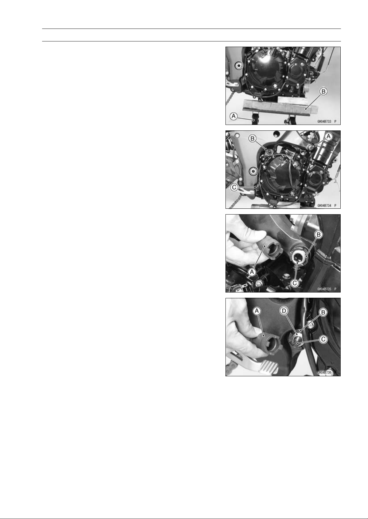
ENGINE REMOVAL/INSTALLATION 8-7
Engine Removal/Installation
•
Support the engine with a suitable stand [A].
○
Put a plank [B] onto the suitable stand for engine balance.
•
Remove:
Upper Engine Mounting Bolt [A] (Both Sides)
Middle Engine Mounting Nut [B] and Bolt
Lower Engine Mounting Nut [C]
•
Using the nut wrench [A], loosen the upper adjusting collar
locknut [B].
Special Tool - Engine Mount Nut Wrench: 57001-1450
•
Using the Hexagon Wrench, turn the adjusting collar [C]
counterclockwise to make the gap between the engine
and adjusting collar.
•
Using the nut wrench [A], loosen the lower adjusting collar
locknut [B].
Special Tool - Engine Mount Nut Wrench: 57001-1450
•
Remove the lower engine mounting bolt [C].
•
Using the Hexagon Wrench, turn the adjusting collar [D]
counterclockwise to make the gap between the engine
and adjusting collar.
•
Using the stand, take out the engine.
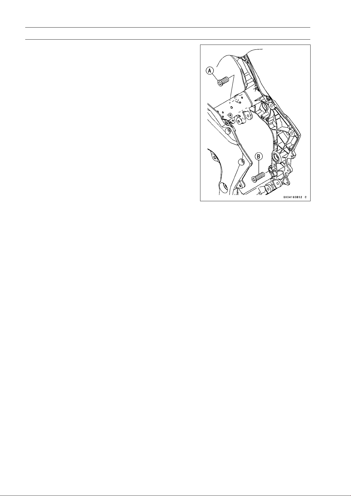
8-8 ENGINE REMOVAL/INSTALLATION
Engine Removal/Installation
Engine Installation
•
Support the engine with a suitable stand.
○
Put a plank onto the suitable stand for engine balance.
•
Apply 2-stroke oil to the upper adjusting collar [A].
•
Screw the upper adjusting collar and lower adjusting col-
lar [B] to the frame.

ENGINE REMOVAL/INSTALLATION 8-9
Engine Removal/Installation
•
Install the engine mounting bolts and nuts, following the specified installing sequence.
○
First, hang the drive chain over the output shaft just before moving the engine into its final position
in the frame.
○
Second, apply a non-parmanent locking agent to the threads of the middle engine bracket bolts [A].
Install the middle engine bracket [B] and tighten the bolts.
Torque - Middle Engine Bracket Bolts: 25 N·m (2.5 kgf·m, 18 ft·lb)
○
Third, insert the lower engine mounting bolt [C].
○
Forth, install the collar [D], and insert the middle engine mounting bolt [E].
○
Fifth, tighten:
Torque - Left Upper Engine Mounting Bolt [F]: 44 N·m (4.5 kgf·m, 32 ft·lb)
○
Sixth, tighten the upper adjusting collar locknut [G] and right upper engine mounting bolt [H] tem-
porarily.
○
Seventh, tighten:
Torque - Lower Adjusting Collar [I]: 9.8 N·m (1.0 kgf·m, 87 in·lb)
○
Eighth, tighten the lower adjusting collar locknut [J] and lower engine mounting nut [K].
Torque - Lower Adjusting Collar Locknut: 49 N·m (5.0 kgf·m, 36 ft·lb)
Lower Engine Mounting Nut: 44 N·m (4.5 kgf·m, 32 ft·lb)
Special Tool - Engine Mount Nut Wrench: 57001-1450
○
Ninth, tighten:
Torque - Middle Engine Mounting Nut [L]: 44 N·m (4.5 kgf·m, 32 ft·lb)
○
Tenth, install the left engine bracket [M], and tighten the mounting bolts evenly.
Torque - Upper Engine Bracket Bolts [N]: 44 N·m (4.5 kgf·m, 32 ft·lb)
Lower Engine Bracket Bolts [O]: 59 N·m (6.0 kgf·m, 44 ft·lb)
○
Eleventh, install the right engine bracket [P] just like the left engine bracket.
○
Twelfth, remove the right upper engine mounting bolt [H].
○
Thirteenth, tighten:
Torque - Upper Adjusting Collar [Q]: 5.0 N·m (0.51 kgf·m, 44 in·lb)
○
Fourteenth, tighten the upper adjusting collar locknut [G].
Torque - Upper Adjusting Collar Locknut: 49 N·m (5.0 kgf·m, 36 ft·lb)
Special Tool - Engine Mount Nut Wrench: 57001-1450
○
Lastly, tighten:
Torque - Right Upper Engine Mounting Bolt [H]: 44 N·m (4.5 kgf·m, 32 ft·lb)
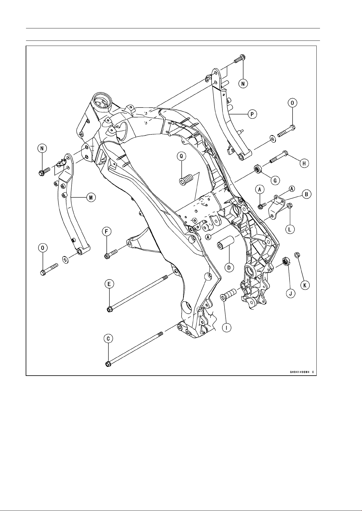
8-10 ENGINE REMOVAL/INSTALLATION
Engine Removal/Installation
•
Run the leads, cables and hoses correctly (see Cable,
Wire, and Hose Routing section in the Appendix chapter).
•
Install the removed parts (see appropriate chapters).
Torque - Engine Ground Cable Terminal Bolt: 9.8 N·m (1.0
kgf·m, 87 in·lb)
•
Adjust:
Throttle Cables (see Throttle Control System Inspection
in the Periodic Maintenance chapter)
Clutch Cable (see Clutch Operation Inspection in the Pe-
riodic Maintenance chapter)
Drive Chain (see Drive Chain Slack Inspection in the
Periodic Maintenance chapter)

ENGINE REMOVAL/INSTALLATION 8-11
Engine Removal/Installation
•
Fill the engine with engine oil (see Engine Oil Change in
the Periodic Maintenance chapter).
•
Fill the engine with coolant (see Coolant Change in the
Periodic Maintenance chapter).


CRANKSHAFT/TRANSMISSION 9-1
9
Crankshaft/Transmission
Table of Contents
Exploded View................................... 9-2
Specifications .................................... 9-6
Special Tools and Sealants ............... 9-8
Crankcase Splitting............................ 9-9
Crankcase Splitting...................... 9-9
Crankcase Assembly ................... 9-10
Crankshaft and Connecting Rods...... 9-16
Crankshaft Removal .................... 9-16
Crankshaft Installation ................. 9-16
Connecting Rod Removal............ 9-16
Connecting Rod Installation......... 9-17
Crankshaft/Connecting Rod
Cleaning.................................... 9-20
Connecting Rod Bend Inspection 9-20
Connecting Rod Twist Inspection. 9-21
Connecting Rod Big End Side
Clearance Inspection ................ 9-21
Connecting Rod Big End
Bearing Insert/Crankpin Wear
Inspection.................................. 9-21
Crankshaft Side Clearance
Inspection.................................. 9-23
Crankshaft Runout Inspection...... 9-24
Crankshaft Main Bearing
Insert/Journal Wear Inspection . 9-24
Balancer ............................................ 9-26
Balancer Removal........................ 9-26
Balancer Installation..................... 9-26
Balancer Adjustment.................... 9-27
Balancer Damper Inspection........ 9-27
Starter Motor Clutch .......................... 9-28
Starter Motor Clutch
Removal/Installation.................. 9-28
Starter Motor Clutch Inspection ... 9-28
Starter Motor Clutch Disassembly 9-28
Starter Motor Clutch Assembly .... 9-28
External Shift Mechanism.................. 9-29
Shift Pedal Removal .................... 9-29
Shift Pedal Installation ................. 9-29
External Shift Mechanism
Removal .................................... 9-29
External Shift Mechanism
Installation................................. 9-30
External Shift Mechanism
Inspection.................................. 9-31
Transmission ..................................... 9-33
Transmission Shaft Removal ....... 9-33
Transmission Shaft Installation .... 9-33
Transmission Shaft Disassembly. 9-33
Transmission Shaft Assembly...... 9-34
Shift Drum and Fork Removal...... 9-38
Shift Drum and Fork Installation... 9-38
Shift Drum Disassembly............... 9-38
Shift Drum Assembly ................... 9-38
Shift Fork Bending Inspection...... 9-38
Shift Fork/Gear Groove Wear
Inspection.................................. 9-39
Shift Fork Guide Pin/Drum
Groove Wear Inspection ........... 9-39
Gear Dog and Gear Dog Hole
Damage Inspection ................... 9-39
Ball Bearing, Needle Bearing, and Oil
Seal................................................. 9-40
Ball and Needle Bearing
Replacement............................. 9-40
Ball and Needle Bearing Wear..... 9-40
Oil Seal Inspection....................... 9-40
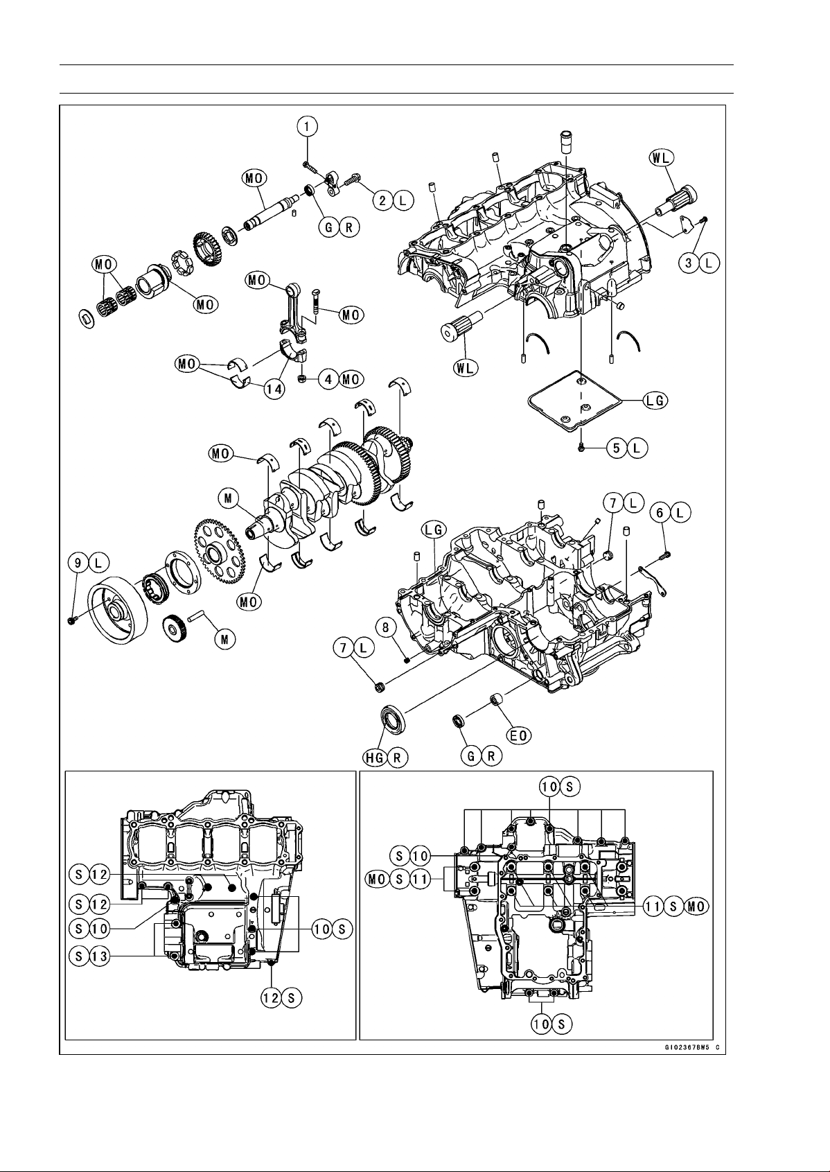
9-2 CRANKSHAFT/TRANSMISSION
Exploded View
CRANKSHAFT/TRANSMISSION 9-3
Exploded View
Torque
No. Fastener
N·m kgf·m ft·lb
Remarks
1 Balancer Shaft Clamp Bolt 9.8 1.0 87 in·lb
2 Balancer Shaft Clamp Lever Bolt 25 2.5 18 L
3
Breather Side Plate Bolt
5.9 0.60 52 in·lb L
4 Connecting Rod Big End Nuts see the text ← ← MO
5 Breather Plate Bolts 9.8 1.0 87 in·lb L
6
Shift Drum Bearing Holder Bolts
12 1.2 106 in·lb L
7 Oil Passage Plugs 20 2.0 15 L
8 Oil Passage Plug 9.8 1.0 87 in·lb
9 Starter Motor Clutch Bolts 12 1.2 106 in·lb L
10 Crankcase Bolts (M7) 20 2.0 15 S
11 Crankcase Bolts (M9) 42 4.2 31 S, MO
12
Crankcase Bolts (M6)
12 1.2 106 in·lb
S
13 Crankcase Bolts (M8) 27 2.8 20 S
14. Do not apply any grease or oil.
EO: Apply engine oil.
G: Apply grease.
HG: Apply high-temperature grease.
L: Apply a non-permanent locking agent.
LG: Apply liquid gasket.
M: Apply molybdenum disulfide grease.
MO: Apply molybdenum disulfide oil solution.
(mixture of the engine oil and molybdenum disulfide grease in a weight ratio 10:1)
R: Replacement Parts
S: Follow the specified tightening sequence.
WL: Apply soap and water solution or rubber lubricant.
WS: Apply water-soluble lubricant (ThreeBond:TB2720C).
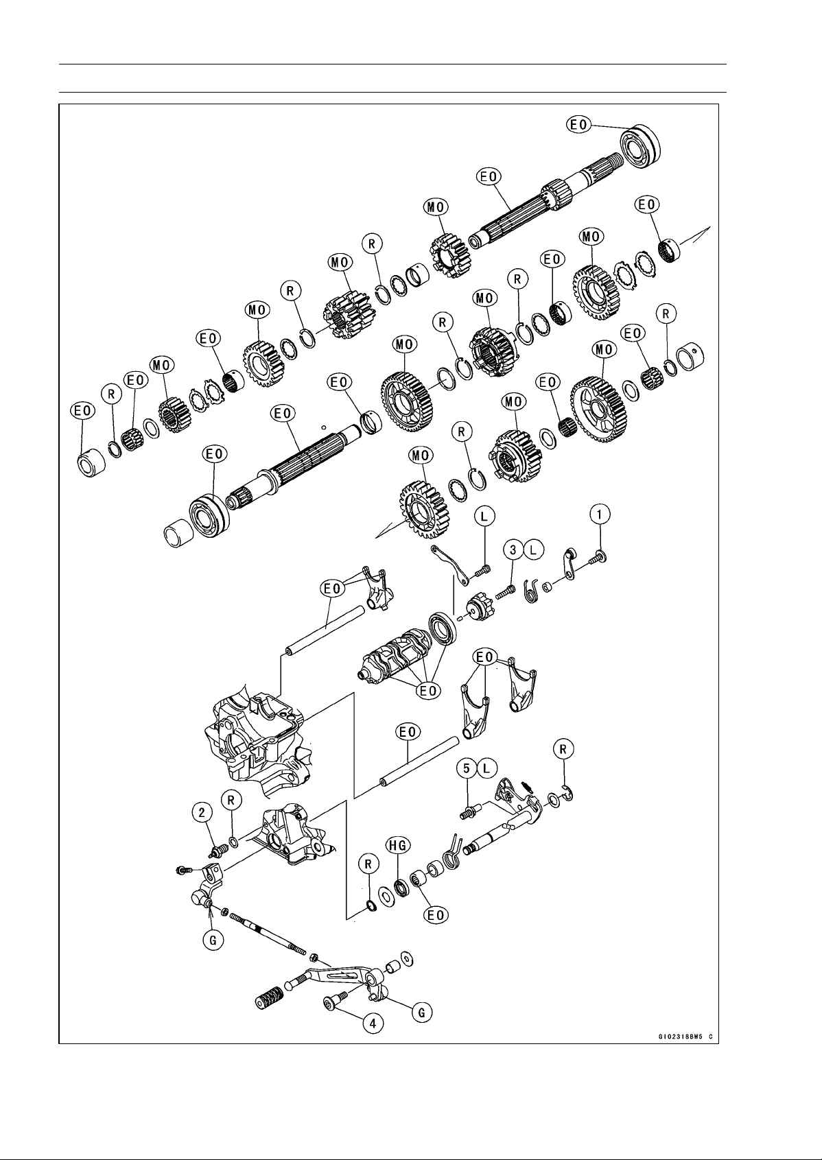
9-4 CRANKSHAFT/TRANSMISSION
Exploded View

CRANKSHAFT/TRANSMISSION 9-5
Exploded View
Torque
No. Fastener
N·m kgf·m ft·lb
Remarks
1 Gear Positioning Lever Bolt 12 1.2 106 in·lb
2 Neutral Switch 15 1.5 11
3
Shift Drum Cam Bolt
12 1.2 106 in·lb L
4 Shift Pedal Mounting Bolt 25 2.5 18
5 Shift Shaft Return Spring Pin 39 4.0 29 L
EO: Apply engine oil.
G: Apply grease.
HG: Apply high-temperature grease.
MO: Apply molybdenum disulfide oil.
(mixture of the engine oil and molybdenum disulfide grease in a weight ratio 10:1)
L: Apply a non-permanent locking agent.
R: Replacement Parts
9-6 CRANKSHAFT/TRANSMISSION
Specifications
Item Standard Service Limit
Crankcase, Crankshaft, Connecting
Rods
Connecting Rod Bend ––– TIR 0.2/100 mm
(0.008/3.94 in.)
Connecting Rod Twist ––– TIR 0.2/100 mm
(0.008/3.94 in.)
Connecting Rod Big End Side
Clearance
0.13 ∼ 0.38 mm (0.0051 ∼ 0.0150 in.) 0.58 mm
(0.023 in.)
Connecting Rod Big End Bearing
Insert/Crankpin Clearance
0.030 ∼ 0.060 mm (0.0012 ∼ 0.0024 in.)
0.10 mm
(0.0039 in.)
Crankpin Diameter: 34.484 ∼ 34.500 mm (1.3576 ∼ 1.3583 in.)
34.47 mm
(1.357 in.)
Marking:
None
34.484 ∼ 34.492 mm (1.3576 ∼ 1.3579 in.)
–––
○
34.493 ∼ 34.500 mm (1.3580 ∼ 1.3583 in.)
–––
Connecting Rod Big End Inside
Diameter:
37.500 ∼ 37.516 mm (1.4764 ∼ 1.4770 in.)
–––
Marking:
None 37.500 ∼ 37.508 mm (1.4764 ∼ 1.4766 in.) –––
○
37.509 ∼ 37.516 mm (1.4767 ∼ 1.4770 in.)
–––
Connecting Rod Big End Bearing
Insert Thickness:
Brown 1.478 ∼ 1.483 mm (0.05819 ∼ 0.05839 in.) –––
Black
1.483 ∼ 1.488 mm (0.05839 ∼ 0.05858 in.)
–––
Blue
1.488 ∼ 1.493 mm (0.05858 ∼ 0.05878 in.)
–––
Connecting Rod Bolt Stretch (Usable Range)
0.20 ∼ 0.32 mm (0.0079 ∼ 0.0126 in.) –––
Crankshaft Side Clearance 0.09 ∼ 0.19 mm (0.0035 ∼ 0.0075 in.) 0.39 mm
(0.0153 in.)
Crankshaft #3 Main Journal Width 23.49 ∼ 23.54 mm (0.9248 ∼ 0.9267 in.)
–––
Crankshaft Runout TIR 0.02 mm (0.0008 in.) or less
TIR 0.05 mm
(0.0020 in.)
Crankshaft Main Bearing
Insert/Journal Clearance
0.010 ∼ 0.034 mm (0.0004 ∼ 0.0013 in.) 0.06 mm
(0.0024 in.)
Crankshaft Main Journal Diameter: 34.984 ∼ 35.000 mm (1.3773 ∼ 1.3780 in.)
34.96 mm
(1.3764 in.)
Marking:
None
34.984 ∼ 34.992 mm (1.3773 ∼ 1.3776 in.)
–––
1 34.993 ∼ 35.000 mm (1.3777 ∼ 1.3780 in.) –––
Crankcase Main Bearing Inside
Diameter:
38.000 ∼ 38.016 mm (1.4961 ∼ 1.4967 in.) –––
Marking
None
38.009 ∼ 38.016 mm (1.4964 ∼ 1.4967 in.)
–––
○
38.000 ∼ 38.008 mm (1.4961 ∼ 1.4963 in.)
–––

CRANKSHAFT/TRANSMISSION 9-7
Specifications
Item Standard Service Limit
Crankshaft Main Bearing Insert
Thickness:
Brown
1.491 ∼ 1.495 mm (0.0587 ∼ 0.0589 in.)
–––
Black 1.495 ∼ 1.499 mm (0.0589 ∼ 0.0590 in.) –––
Blue 1.499 ∼ 1.503 mm (0.0590 ∼ 0.0592 in.) –––
Transmission
Shift Fork Ear Thickness 5.9 ∼ 6.0 mm (0.232 ∼ 0.236 in.) 5.8 mm
(0.228 in.)
Gear Groove Width 6.05 ∼ 6.15 mm (0.238 ∼ 0.242 in.) 6.25 mm
(0.246 in.)
Shift Fork Guide Pin Diameter 6.9 ∼ 7.0 mm (0.272 ∼ 0.276 in.)
6.8 mm
(0.268 in.)
Shift Drum Groove Width 7.05 ∼ 7.20 mm (0.278 ∼ 0.283 in.) 7.3 mm
(0.287 in.)
Connecting Rod Big End Bearing Insert Selection
Bearing Insert
Con-rod Big End
Inside Diameter
Marking
Crankpin Diameter
Marking
Size Color Part Number
None
○
Brown 92139-0124
None None
○ ○
Black 92139-0123
○
None Blue 92139-0122
Crankshaft Main Bearing Insert Selecti
on
Bearing Insert*Crankcase Main
Bearing Inside
Diameter Marking
Crankshaft Main
Journal Diameter
Marking
Size Color Part Number Journal Nos.
92139-0034 2, 4
○
1 Brown
92139-0219 1, 3, 5
None 1 92139-0033 2, 4
○
None
Black
92139-0218 1, 3, 5
92139-0032 2, 4
None None Blue
92139-0217 1, 3, 5
*: The bearing inserts for Nos. 2 and 4 journals have an oil groove, respectively.
Crankshaft, Camshaft Chain, Camshaft Sprocket Selection
Part Number
Engine Number/Model
Crankshaft Camshaft Chain Camshaft Sprocket
∼ ZRT00DE016592 13031-0125 92057-1453 12046-0083
ZRT00DE016593 ∼ 13031-0710 92057-0202 12046-0563
ZR1000DD/ED 13031-0710 92057-0202 12046-0564

9-8 CRANKSHAFT/TRANSMISSION
Special Tools and Sealants
Bearing Puller:
57001-135
Outside Circlip Pliers:
57001-144
Bearing Puller Adapter:
57001-317
Bearing Driver, 32:
57001-382
Bearing Driver Set:
57001-1129
Flywheel Holder:
57001-1313
Liquid Gasket, TB1216B:
92104-1064
Liquid Gasket, TB1207B:
92104-2068
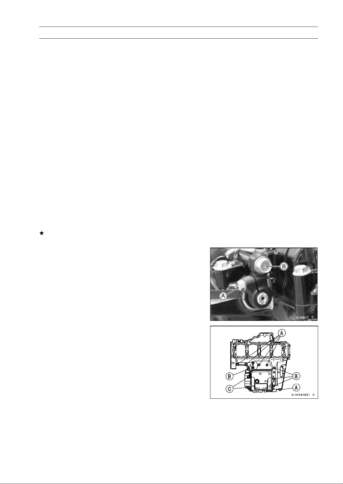
CRANKSHAFT/TRANSMISSION 9-9
Crankcase Splitting
Crankcase Splitting
•
Remove the engine (see Engine Removal in the Engine
Removal/Installation chapter).
•
Set the engine on a clean surface and hold the engine
steady while parts are being removed.
•
Remove:
Cylinder (see Cylinder Removal in the Engine Top End
chapter)
Clutch (see Clutch Removal in the Clutch chapter)
External Shift Mechanism (see External Shift Mecha-
nism Removal)
Starter Motor (see Starter Motor Removal in the Electri-
cal System chapter)
Oil Pump (see Oil Pump Removal in the Engine Lubri-
cation System chapter)
Alternator Rotor (see Alternator Rotor Removal in the
Electrical System chapter)
Oil Filter (see Oil Filter Replacement in the Periodic
Maintenance chapter)
Oil Cooler (see Oil Cooler Removal in the Engine Lubri-
cation System chapter)
Oil Pipe (see Oil Pipe Removal in the Engine Lubrication
System chapter)
Oil Pressure Relief Valve (see Oil Pressure Relief Valve
Removal in the Engine Lubrication System chapter)
If the crankshaft is to be removed, remove the pistons
(see Piston Removal in the Engine Top End chapter).
•
Remove:
Balancer Shaft Clamp Bolt [A]
Balancer Shaft Clamp Lever Bolt [B]
•
Remove the upper crankcase bolts following the specified
sequence.
○
First, loosen the M6 bolts [A]
○
Second, loosen the M7 bolts [B]
○
Lastly, loosen the M8 bolts [C]
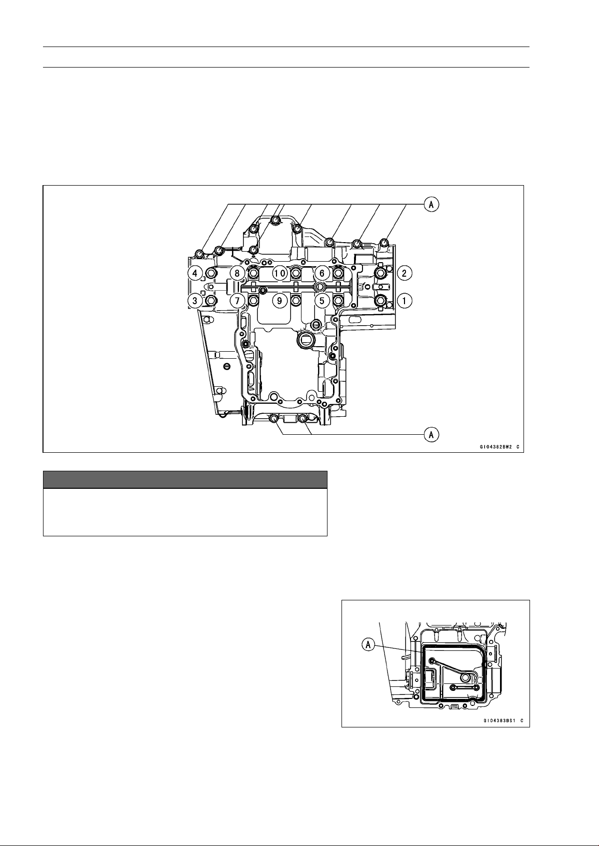
9-10 CRANKSHAFT/TRANSMISSION
Crankcase Splitting
•
Remove the lower crankcase bolts, following the specified
sequence.
○
First, loosen the M7 bolts [A].
○
Lastly, loosen the M9 bolts as shown sequence [1 ∼ 10]
in the figure.
•
Tap lightly around the crankcase mating surface with a
plastic mallet, and split the crankcase.
○
Take care not to damage the crankcase.
Crankcase Assembly
NOTICE
The upper and lower crankcase halves are ma-
chined at the factory in the assembled state, so the
crankcase halves must be replaced as a set.
•
With a high flash-point solvent, clean off the mating sur-
faces of the crankcase halves and wipe dry.
•
Using compressed air, blow out the oil passages in the
crankcase halves.
•
Apply liquid gasket to the breather plate mating surface
[A] 1 mm (0.04 in.) or more thick, and then install the
breather plate.
Sealant - Liquid Gasket, TB1207B: 92104-2068
NOTE
○
Make the application finish within 7 minutes when the
liquid gasket to the mating surface of the breather plate
is applied.
○
Moreover fit the plate and tighten the bolts just after
application of the liquid gasket.
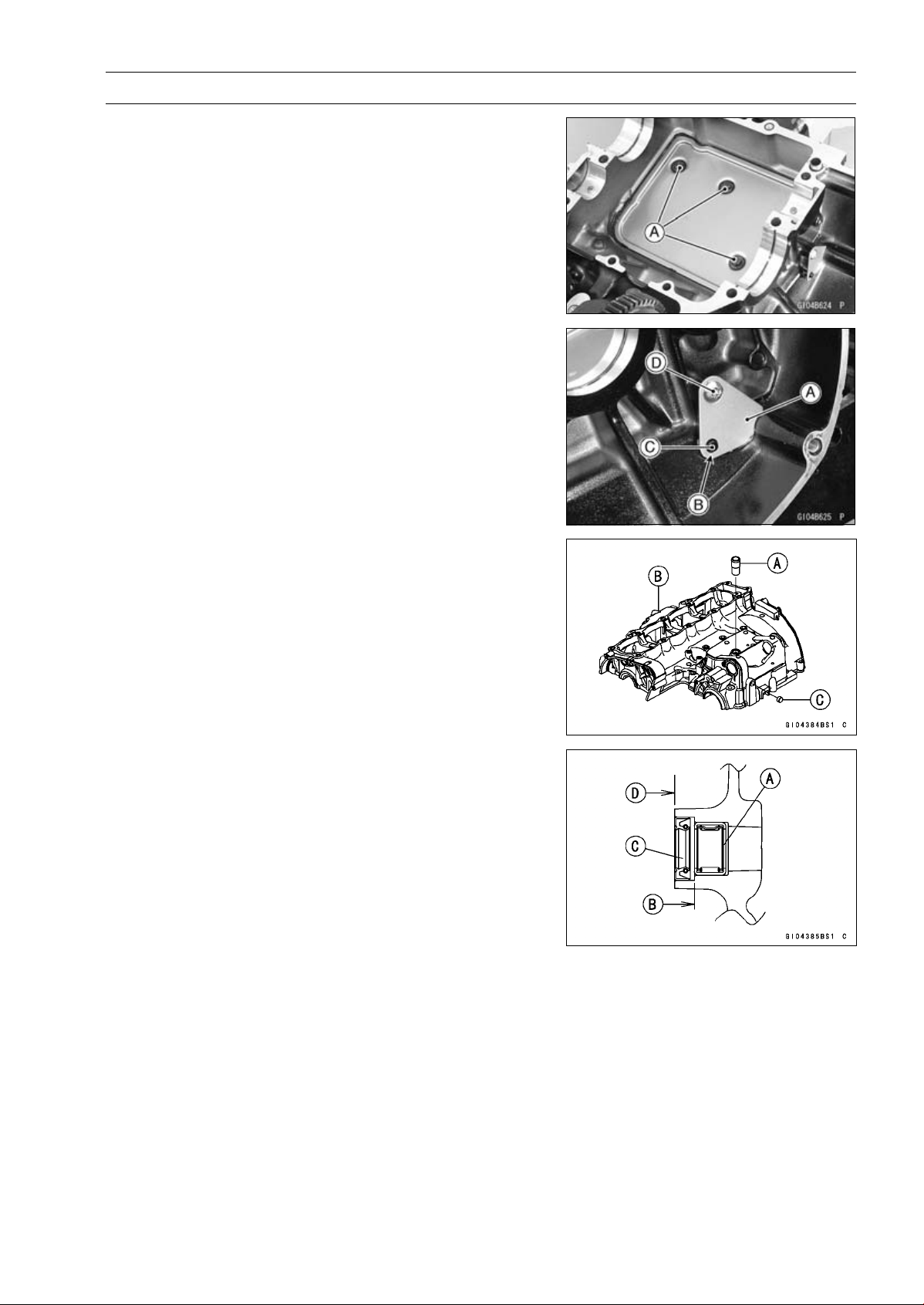
CRANKSHAFT/TRANSMISSION 9-11
Crankcase Splitting
•
Apply a non-permanent locking agent to the threads of
the breather plate bolts [A] and tighten them.
Torque - Breather Plate Bolts: 9.8 N·m (1.0 kgf·m, 87 in·lb)
•
Install the breather side plate [A] so that the plate hole [B]
fit the projection [C] of the upper crankcase.
•
Apply a non-parmanent locking agent to the threads of
the breather side plate bolt [D] and tighten it.
Torque - Breather Side Plate Bolt: 5.9 N·m (0.60 kgf·m, 52
in·lb)
•
Press and insert the fitting [A] in the upper crankcase [B]
until it is bottomed.
Special Tool - Bearing Driver Set: 57001-1129
•
Press and insert the plug [C] in the upper crankcase so
that the plug is deeper than crankcase surface.
•
Press and insert the new needle bearing [A] for the shift
shaft so that its marked side faces outside and its surface
[B] is flush with the end of the hole.
•
Install the new oil seal [C] so that its surface [D] is flush
with the end of the hole.
•
Apply grease to the oil seal lips.
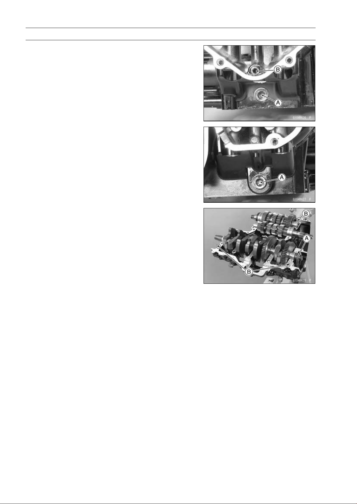
9-12 CRANKSHAFT/TRANSMISSION
Crankcase Splitting
•
Apply a non-parmanent locking agent to the oil passage
plugs [A], and tighten them.
Torque - Oil Passage Plugs: 20 N·m (2.0 kgf·m, 15 ft·lb)
•
Install the oil passage plug [B] in the lower crankcase, and
tighten it.
Torque - Oil Passage Plug: 9.8 N·m (1.0 kgf·m, 87 in·lb)
•
Install:
Crankshaft (see Crankshaft Installation)
Connecting Rods (see Connecting Rod Installation)
Camshaft Chain [A]
Transmission Shafts and Gears (see Transmission Shaft
Installation)
Dowel Pins [B]
Shift Drum (see Shift Drum and Fork Installation)
Shift Forks and Shift Rods (see Shift Drum and Fork In-
stallation)
•
Before fitting the lower case on the upper case, check the
following.
○
Be sure to hang the camshaft chain on the crankshaft.
○
Check to see that the shift drum and transmission gears
are in the neutral position.
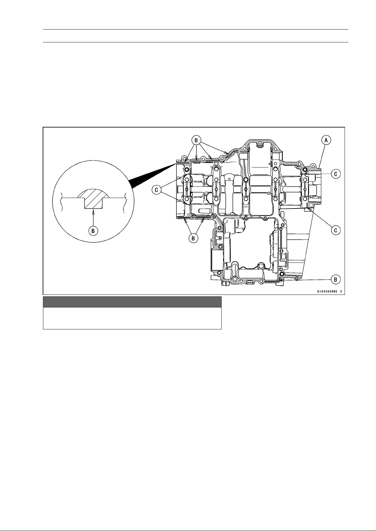
CRANKSHAFT/TRANSMISSION 9-13
Crankcase Splitting
•
Apply liquid gasket [A] to the mating surface of the lower
crankcase half.
Sealant - Liquid Gasket, TB1216B: 92104-1064
NOTE
○
Especially, apply a sealant so that it shall be filled up on
the grooves [B].
○
Do not apply liquid gasket to the inside of the groove
[C].
NOTICE
Do not apply liquid gasket around the crankshaft
main bearing inserts and oil passage holes.
•
Fit the lower crankcase to the upper crankcase.
NOTE
○
Make the application finish within 20 minutes when the
liquid gasket to the mating surface of the crankcase half
is applied.
○
Moreover fit the case and tighten the bolts just after
application of the liquid gasket.
•
The M9 bolts have copper plated washers, replace them
with new ones.
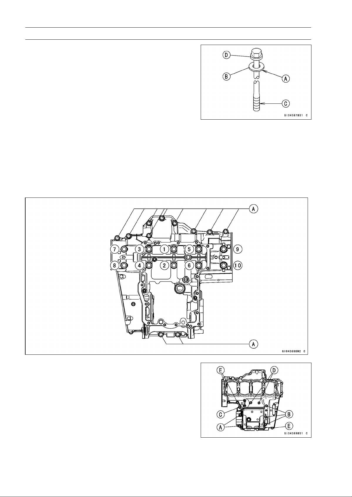
9-14 CRANKSHAFT/TRANSMISSION
Crankcase Splitting
•
Apply molybdenum disulfide oil solution to the lower
seating surface [A] on the copper plated washer [B] and
threads [C] of the M9 bolts [D].
•
Tighten the lower crankcase bolts using the following
steps.
○
Following the sequence numbers on the lower crankcase
half, tighten the M9 bolts [1 ∼10] with copper plated wash-
ers.
Torque - Crankcase Bolts (M9): 42 N·m (4.2 kgf·m, 31 ft·lb)
○
Tighten the M7 bolts [A].
Torque - Crankcase Bolts (M7): 20 N·m (2.0 kgf·m, 15 ft·lb)
•
Tighten the upper crankcase bolts follow in the specified
sequence.
○
First, tighten the M8 bolts [A].
Torque - Crankcase Bolts (M8): 27 N·m (2.8 kgf·m, 20 ft·lb)
○
Second, tighten the M7 bolts.
L=85mm(3.35in.) [B]
L=50mm(1.97in.) [C]
Torque - Crankcase Bolts (M7): 20 N·m (2.0 kgf·m, 15 ft·lb)
○
Lastly, tighten the M6 bolts.
L=68mm(2.69in.) [D]
L=40mm(1.57in.) [E]
Torque - Crankcase Bolts (M6): 12 N·m (1.2 kgf·m, 106 ft·lb)

CRANKSHAFT/TRANSMISSION 9-15
Crankcase Splitting
•
After tightening all crankcase bolts, check the following
items.
○
Wipe up the liquid gasket that seeps out around the
crankcase mating surface.
○
Crankshaft and transmission shafts turn freely.
○
While spinning the output shaft, gears shift smoothly from
the 1st to 6th gear, and 6th to 1st.
○
When the output shaft stays still, the gear can not be
shifted to 2nd gear or other higher gear positions.
•
Install the removed parts (see appropriate chapters).
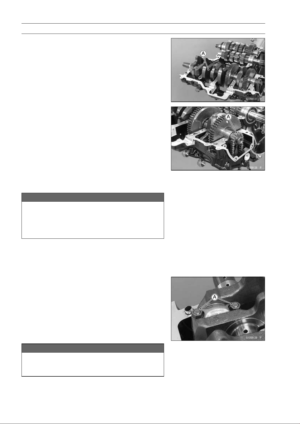
9-16 CRANKSHAFT/TRANSMISSION
Crankshaft and Connecting Rods
Crankshaft Removal
•
Split the crankcase (see Crankcase Splitting).
•
Remove:
Balancer (see Balancer Removal)
Crankshaft [A]
Crankshaft Installation
NOTE
○
The crankshaft, camshaft chain and camshaft sprock-
ets are different between the early production models
(Engine Number:
∼
ZRT00DE016592), the late produc-
tion models (Engine Number: ZRT00DE016593
∼
) and
ZR1000DD/ED.
○
Do not use these parts in a combination of the ear-
lier production models, later production models and
ZR1000DD/ED (see the table of specification for the
Crankshaft, Camshaft Chain and Camshaft Sprocket
Selection) .
NOTICE
If the crankshaft, bearing inserts, or crankcase
halves are replaced with new ones, select the bear-
ing inserts and check clearance with a plastigage
(press gauge) before assembling engine to be sure
the correct bearing inserts are installed.
•
Apply molybdenum disulfide oil solution to the crankshaft
main bearing inserts.
•
Install the crankshaft with the camshaft chain [A] hanging
on it.
•
Install the balancer (see Balancer Installation).
Connecting Rod Removal
•
Split the crankcase (see Crankcase Splitting).
•
Remove the connecting rod big end nuts [A].
•
Remove the crankshaft.
NOTE
○
Mark and record the locations of the connecting rods
and their big end caps so that they can be reassembled
in their original positions.
•
Remove the connecting rods from the crankshaft.
NOTICE
Discard the connecting rod bolts. To prevent dam-
age to the crankpin surfaces, do not allow the con-
necting rod bolts to bump against the crankpins.

CRANKSHAFT/TRANSMISSION 9-17
Crankshaft and Connecting Rods
Connecting Rod Installation
NOTICE
To minimize vibration, the connecting rods should
have the same weight mark.
BigEndCap[A]
Connecting Rod [B]
Weight Mark, Alphabet [C]
Diameter Mark [D]: “
○
”ornomark
NOTICE
If the connecting rods, big end bearing inserts, or
crankshaft are replaced with new ones, select the
bearing insert and check clearance with a plasti-
gage (press gauge) before assembling engine to be
sure the correct bearing inserts are installed.
•
Apply molybdenum disulfide oil solution [A] to the inner
surfaces of upper and lower bearing inserts.
•
Do not apply any grease or oil to the cap inside and cap
insert outside [B].
•
Install the inserts so that their nails [C] are on the same
side and fit them into the recess of the connecting rod and
cap.
NOTICE
Wrong application of oil and grease could cause
bearing damage.
○
When installing the inserts [A], be careful not to damage
the insert surface with the edge of the connecting rod [B]
or the cap [C]. One way to install inserts is as follows.
Installation [D] to Cap
Installation [E] to Connecting Rod
Push [F]
Spare Dowel Pin [G]
Connecting Rod Bolts [H]
•
Install the cap on the connecting rod, aligning the weight
and diameter marks.
•
Remove debris and clean the surface of inserts.
•
Apply molybdenum disulfide oil solution [MO] to the
threads and seating surfaces of the big end nuts and
bolts.
9-18 CRANKSHAFT/TRANSMISSION
Crankshaft and Connecting Rods
•
Install the crankshaft (see Crankshaft Installation).
•
Install each connecting rod on its original crankpin.
○
The connecting rod big end is bolted using the “plastic
region fastening method”.
○
This method precisely achieves the needed clamping
force without exceeding it unnecessarily, allowing the
use of thinner, lighter bolts further decreasing connecting
rod weight.
○
There are two types of the plastic region fastening. One is
a bolt length measurement method and other is a rotation
angle method. Observe one of the following two, but the
bolt length measurement method is preferable because
this is a more reliable way to tighten the big end nuts.
NOTICE
The connecting rod bolts are designed to stretch
when tightened. Never reuse the connecting rod
bolts. See the table below for correct bolt and nut
usage.
NOTICE
Be careful not to overtighten the nuts.
The bolts must be positioned on the seating surface
correctly to prevent the bolt heads from hitting the
crankcase.
(1) Bolt Length Measurement Method
•
Be sure to clean the bolts, nuts, and connecting rods
thoroughly with a high flash-point solvent, because the
new connecting rods, bolts, and nuts are treated with an
anti-rust solution.
WARNING
Gasoline and low flash-point solvents can be
flammable and/or explosive and cause severe
burns. Clean the bolts, nuts, and connecting rods
in a well-ventilated area, and take care that there
are no sparks or flame anywhere near the working
area; this includes any appliance with a pilot light.
Do not use gasoline or a low flash-point solvent to
clean them.
NOTICE
Immediately dry the bolts and nuts with com-
pressed air after cleaning.
Clean and dry the bolts and nuts completely.

CRANKSHAFT/TRANSMISSION 9-19
Crankshaft and Connecting Rods
•
Install new bolts and nuts in reused connecting rod.
If the connecting rod assy was replaced, use the bolts and
nuts attached to the new connecting rod assy.
•
Apply a small amount of molybdenum disulfide oil solution
to the following portions.
Threads [A] of Bolts and Nuts
Seating Surfaces [B] of Nuts and Connecting Rod Caps
•
Dent both bolt head and bolt tip with a punch as shown in
the figure.
•
Before tightening, use a point micrometer to measure the
length of new connecting rod bolts and record the values
to find the bolt stretch.
Connecting Rod [A]
Dent here with a punch [B].
Nuts [C]
Fit micrometer pins into dents [D].
•
Tighten the big end nuts until the bolt elongation reaches
the length specified as follows.
Bolt Length after
tightening
–
Bolt Length before
tightening
=
Bolt Stretch
Connecting Rod Bolt Stretch
Usable Range: 0.20
∼ 0.32 mm (0.0079 ∼ 0.0126 in.)
•
Check the length of the connecting rod bolts.
If the stretch is more than the usable range, the bolt has
stretched too much. An overelongated bolt may break in
use.
(2) Rotation Angle Method
If you do not have a point micrometer, you may tighten
the nuts using the “Rotation Angle Method”.
•
Be sure to clean the bolts, nuts and connecting rods thor-
oughly with a high-flash point solvent, because the new
connecting rods, bolts and nuts are treated with an anti
-rust solution.
WARNING
Gasoline and low flash-point solvents can be
flammable and/or explosive and cause severe
burns. Clean the bolts, nuts, and connecting rods
in a well-ventilated area, and take care that there
are no sparks or flame anywhere near the working
area; this includes any appliance with a pilot light.
Do not use gasoline or a low flash-point solvent to
clean them.
NOTICE
Immediately dry the bolts and nuts with com-
pressed air after cleaning.
Clean and dry the bolts and nuts completely.
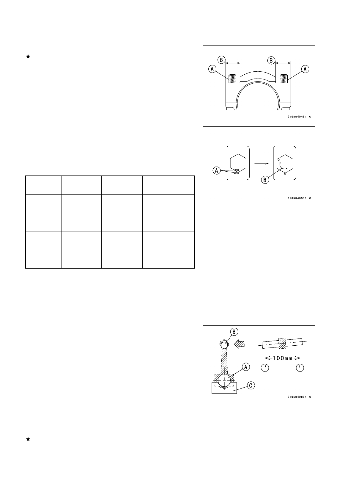
9-20 CRANKSHAFT/TRANSMISSION
Crankshaft and Connecting Rods
•
Install new bolts and nuts in reused connecting rods.
If the connecting rod assy was replaced, use the bolts and
nuts attached to the new connecting rod assy.
•
Apply a small amount of molybdenum disulfide oil solution
to the following portions.
Threads [A] of Bolts and Nuts
Seating Surfaces [B] of Nuts and Connecting Rod Caps
•
First, tighten the nuts to the specified torque. See the
table below.
•
Next, tighten the nuts 120° ±5° .
○
Mark [A] the connecting rod big end caps and nuts so that
nuts can be turned 120° [B] properly.
○
Tighten the hexagon nut by 2 corners.
Torque + Angle
Connecting
Rod Assy
Bolt Nut
N·m (kgf·m, ft·lb)
Attached to
22 (2.2, 16)
new con-rod
+120°
20 (2.0, 15)
New
Use the bolts
attached to
new con-rod.
New
+120°
26 (2.7, 19)
Used
+120°
26 (2.7, 19)
Used
Replace the
bolts with new
ones.
New
+120°
Crankshaft/Connecting Rod Cleaning
•
After removing the connecting rods from the crankshaft,
clean them with a high flash-point solvent.
•
Blow the crankshaft oil passages with compressed air to
remove any foreign particles or residue that may have
accumulated in the passages.
Connecting Rod Bend Inspection
•
Remove the connecting rod big end bearing inserts, and
reinstall the connecting rod big end cap.
•
Select an arbor [A] of the same diameter as the connect-
ing rod big end, and insert the arbor through the connect-
ing rod big end.
•
Select an arbor of the same diameter as the piston pin
and at least 100 mm (3.94 in.) long, and insert the arbor
[B] through the connecting rod small end.
•
On a surface plate, set the big-end arbor on V block [C].
•
With the connecting rod held vertically, use a height
gauge to measure the difference in the height of the
arbor above the surface plate over a 100 mm (3.94 in.)
length to determine the amount of connecting rod bend.
If connecting rod bend exceeds the service limit, the con-
necting rod must be replaced.
Connecting Rod Bend
Service Limit: TIR 0.2/100 mm (0.008/3.94 in.)
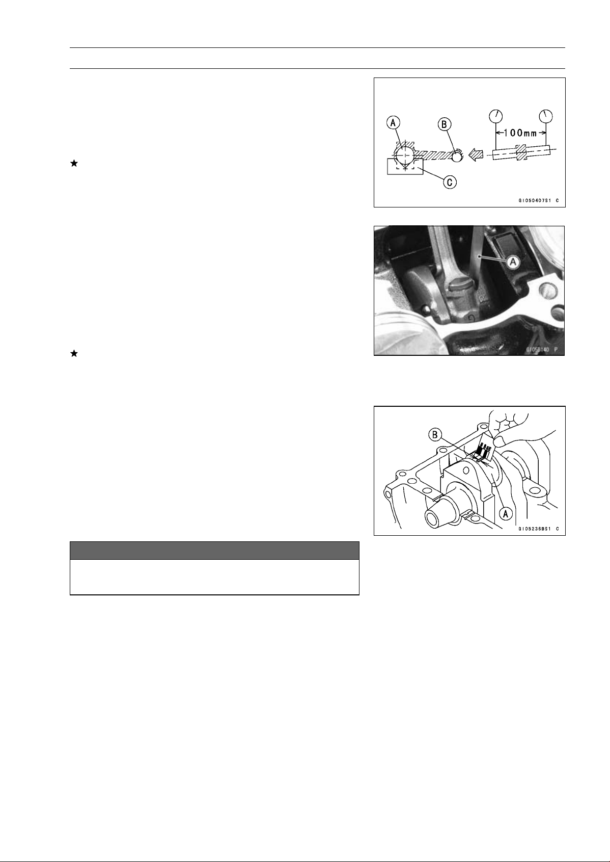
CRANKSHAFT/TRANSMISSION 9-21
Crankshaft and Connecting Rods
Connecting Rod Twist Inspection
•
With the big-end arbor [A] still on V block [C], hold the
connecting rod horizontally and measure the amount that
the arbor [B] varies from being paralleled with the surface
plate over a 100 mm (3.94 in.) length of the arbor to de-
termine the amount of connecting rod twist.
If connecting rod twist exceeds the service limit, the con-
necting rod must be replaced.
Connecting Rod Twist
Service Limit: TIR 0.2/100 mm (0.008/3.94 in.)
Connecting Rod Big End Side Clearance
Inspection
•
Measure connecting rod big end side clearance.
○
Insert a thickness gauge [A] between the big end and ei-
ther crank web to determine clearance.
Connecting Rod Big End Side Clearance
Standard: 0.13
∼ 0.38 mm (0.0051 ∼ 0.0150 in.)
Service Limit: 0.58 mm (0.023 in.)
If the clearance exceeds the service limit, replace the con-
necting rod with new one and then check clearance again.
If clearance is too large after connecting rod replacement,
the crankshaft also must be replaced.
Connecting Rod Big End Bearing Insert/Crankpin
Wear Inspection
•
Measure the bearing insert/crankpin [A] clearance with
plastigage [B].
•
Tighten the big end nuts to the specified torque (see Con-
necting Rod Installation).
NOTE
○
Do not move the connecting rod and crankshaft during
clearance measurement.
NOTICE
After measurement, replace the connecting rod
bolts.
Connecting Rod Big End Bearing Insert/Crankpin Clearance
Standard: 0.030
∼ 0.060 mm (0.0012 ∼ 0.0024 in.)
Service Limit: 0.10 mm (0.0039 in.)
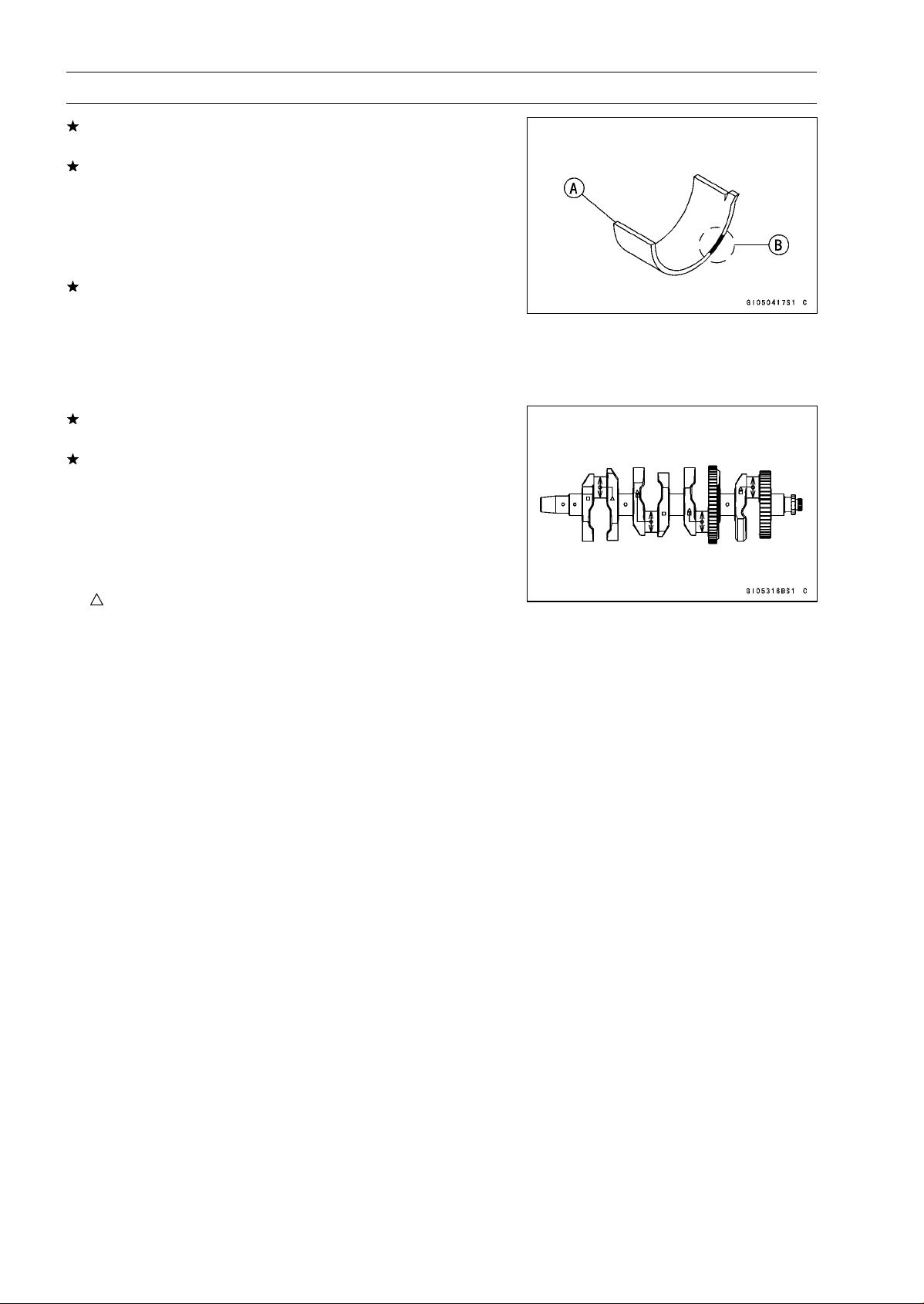
9-22 CRANKSHAFT/TRANSMISSION
Crankshaft and Connecting Rods
If the clearance is within the standard, no bearing replace-
ment is required.
If the clearance is between 0.061 mm (0.0024 in.) and
the service limit (0.10 mm, 0.0039 in.), replace the bear-
ing inserts [A] with inserts painted blue [B]. Check in-
sert/crankpin clearance with the plastigage. The clear-
ance may exceed the standard slightly, but it must not be
less than the minimum in order to avoid bearing seizure.
If the clearance exceeds the service limit, measure the
diameter of the crankpins.
Crankpin Diameter
Standard: 34.484
∼ 34.500 mm (1.3576 ∼ 1.3583 in.)
Service Limit: 34.47 mm (1.357 in.)
If any crankpin has worn past the service limit, replace the
crankshaft with a new one.
If the measured crankpin diameters are not less than the
service limit, but do not coincide with the original diameter
markings on the crankshaft, make new marks on it.
Crankpin Diameter Marks
None
34.484
∼ 34.492 mm (1.3576 ∼ 1.3579 in.)
○
34.493
∼ 34.500 mm (1.3580 ∼ 1.3583 in.)
: Crankpin Diameter Marks, “
○
”ornomark.
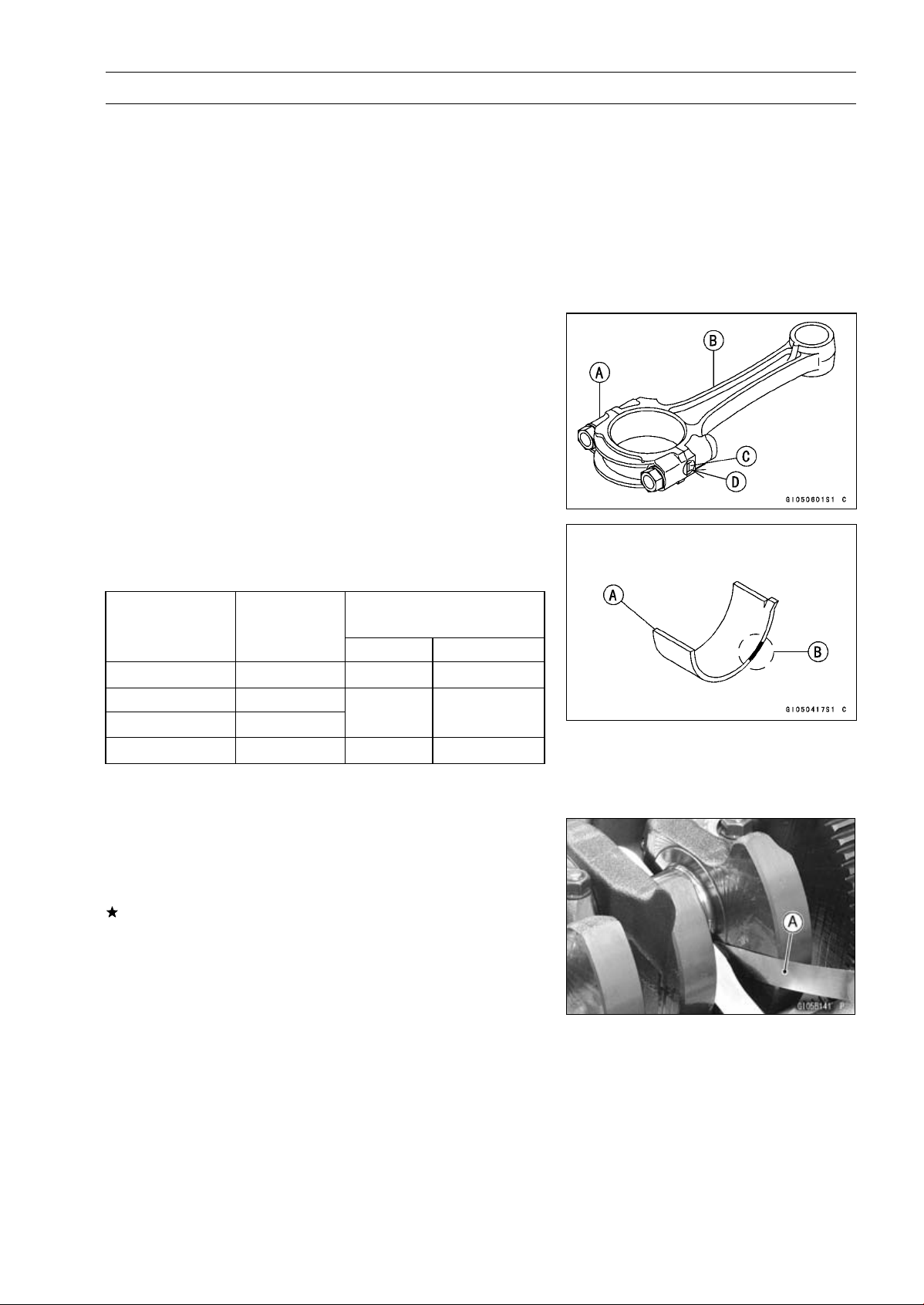
CRANKSHAFT/TRANSMISSION 9-23
Crankshaft and Connecting Rods
•
Measure the connecting rod big end inside diameter, and
mark each connecting rod big end in accordance with the
inside diameter.
•
Tighten the connecting rod big end nuts to the specified
torque (see Connecting Rod Installation).
NOTE
○
The mark already on the big end should almost coincide
with the measurement.
Connecting Rod Big End Inside Diameter Marks
None
37.500
∼ 37.508 mm (1.4764 ∼ 1.4766 in.)
○
37.509
∼ 37.516 mm (1.4767 ∼ 1.4770 in.)
BigEndCap[A]
Connecting Rod [B]
Weight Mark, Alphabet [C]
Diameter Mark (Around Weight Mark) [D]: “
○
”orno
mark
•
Select the proper bearing insert [A] in accordance with the
combination of the connecting rod and crankshaft coding.
Size Color [B]
Bearing Insert
Con-rod Big End
Inside Diameter
Marking
Crankpin
Diameter
Marking
Size Color
Part Number
None
○
Brown 92139-0124
None None
○ ○
Black 92139-0123
○
None Blue 92139-0122
•
Install the new inserts in the connecting rod and check
insert/crankpin clearance with the plastigage.
Crankshaft Side Clearance Inspection
•
Insert a thickness gauge [A] between the crankcase main
bearing and the crank web at the No.3 journal to deter-
mine clearance.
If the clearance exceeds the service limit, replace the
crankcase halves as a set.
NOTE
○
The upper and lower crankcase halves are machined
at the factory in the assembled state, so the crankcase
halves must be replaced as a set.
Crankshaft Side Clearance
Standard: 0.09
∼ 0.19 mm (0.0035 ∼ 0.0075 in.)
Service Limit: 0.39 mm (0.0153 in.)

9-24 CRANKSHAFT/TRANSMISSION
Crankshaft and Connecting Rods
Crankshaft Runout Inspection
•
Measure the crankshaft runout.
If the measurement exceeds the service limit, replace the
crankshaft.
Crankshaft Runout
Standard: TIR 0.02 mm (0.0008 in.) or less
Service Limit: TIR 0.05 mm (0.0020 in.)
Crankshaft Main Bearing Insert/Journal Wear
Inspection
•
Using a plastigage (press gauge) [A], measure the bear-
ing insert/journal [B] clearance.
NOTE
○
Tighten the crankcase bolts to the specified torque (see
Crankcase Assembly).
○
Do not turn the crankshaft during clearance measure-
ment.
○
Journal clearance less than 0.025 mm (0.00098 in.) can
not be measured by plastigage, however, using genuine
parts maintains the minimum standard clearance.
Crankshaft Main Bearing Insert/Journal Clearance
Standard: 0.010
∼ 0.034 mm (0.0004 ∼ 0.0013 in.)
Service Limit: 0.06 mm (0.0024 in.)
If the clearance is within the standard, no bearing replace-
ment is required.
If the clearance is between 0.035 mm (0.0014 in.) and the
service limit (0.06 mm, 0.0024 in.), replace the bearing in-
serts [A] with inserts painted blue [B]. Check insert/journal
clearance with the plastigage. The clearance may exceed
the standard slightly, but it must not be less than the min-
imum in order to avoid bearing seizure.
If the clearance exceeds the service limit, measure the
diameter of the crankshaft main journal.
Crankshaft Main Journal Diameter
Standard: 34.984
∼ 35.000 mm (1.3773 ∼ 1.3780 in.)
Service Limit: 34.96 mm (1.3764 in.)
If any journal has worn past the service limit, replace the
crankshaft with a new one.
If the measured journal diameters are not less than the
service limit, but do not coincide with the original diameter
markings on the crankshaft, make new marks on it.
Crankshaft Main Journal Diameter Marks
None
34.984
∼ 34.992 mm (1.3773 ∼ 1.3776 in.)
1
34.993
∼ 35.000 mm (1.3777 ∼ 1.3780 in.)
□: Crankshaft Main Journal Diameter Marks, “1” or no
mark.
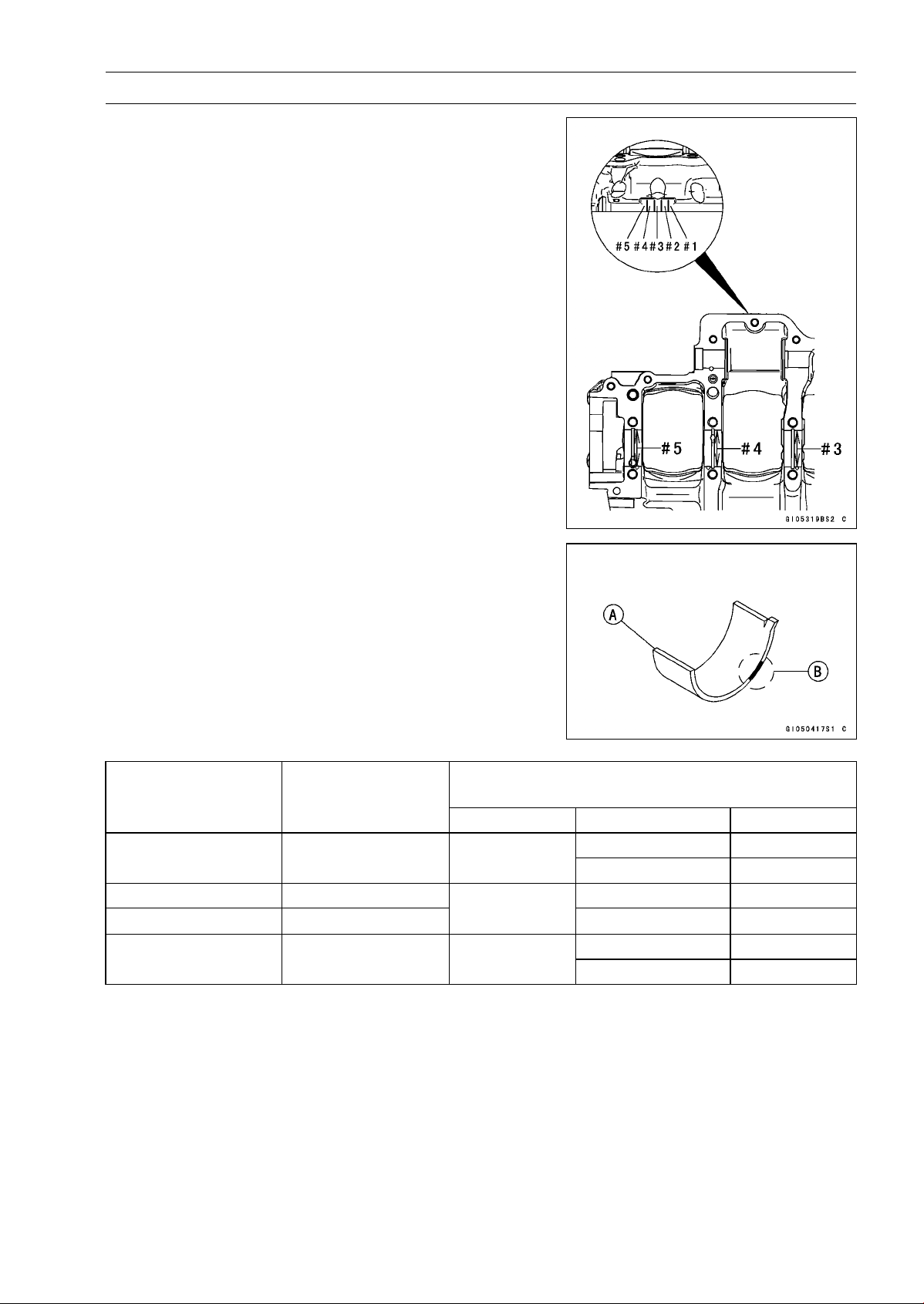
CRANKSHAFT/TRANSMISSION 9-25
Crankshaft and Connecting Rods
•
Measure the main bearing inside diameter, and mark the
upper crankcase half in accordance with the inside diam-
eter.
Crankcase Main Bearing Inside Diameter Marks: “
○
”or
no mark.
•
Tighten the crankcase bolts to the specified torque (see
Crankcase Assembly).
NOTE
○
The mark already on the upper crankcase half should
almost coincide with the measurement.
Crankcase Main Bearing Inside Diameter Marks
○
38.000
∼ 38.008 mm (1.4961 ∼ 1.4963 in.)
None
38.009
∼ 38.016 mm (1.4964 ∼ 1.4967 in.)
•
Select the proper bearing insert [A] in accordance with the
combination of the crankcase and crankshaft coding.
Size Color [B]
Bearing Insert*
Crankcase Main
Bearing Inside
Diameter Marking
Crankshaft Main
Journal Diameter
Marking
Size Color Part Number Journal Nos.
92139-0034 2, 4
○
1 Brown
92139-0219 1, 3, 5
None 1 92139-0033 2, 4
○
None
Black
92139-0218 1, 3, 5
92139-0032 2, 4
None None Blue
92139-0217 1, 3, 5
* The bearing inserts for Nos. 2 and 4 journals have an oil groove, respectively.
•
Install the new inserts in the crankcase halves and check
insert/journal clearance with the plastigage.
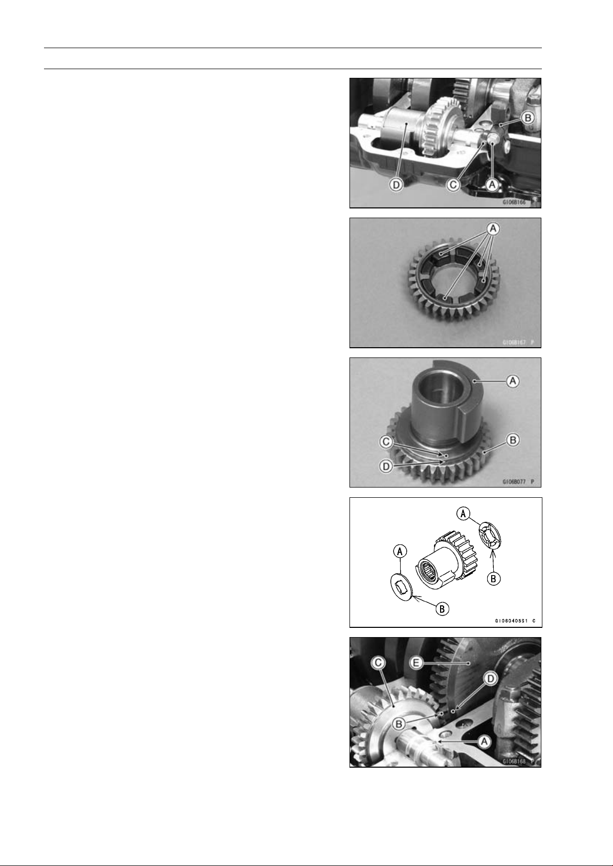
9-26 CRANKSHAFT/TRANSMISSION
Balancer
Balancer Removal
•
Split the crankcase (see Crankcase Splitting).
•
Unscrew:
Balancer Shaft Clamp Bolt [A]
Balancer Shaft Lever [B]
Oil Seal [C]
•
Remove the balancer [D] from the upper crankcase half.
Balancer Installation
•
Check that the rubber dampers [A] are in place as shown
in the figure.
•
Apply molybdenum disulfide oil solution to the damper
contact portions of the balancer weight.
•
Install the balancer weight [A] into the gear [B].
○
Align the punch mark [C] of the balancer weight to the
groove [D] of the gear.
•
Apply molybdenum disulfide oil solution to the needle
bearings. Insert the needle bearings.
•
Fit the copper washers [A] on both ends of the weight and
gear assembly. The projected sides [B] face inward.
•
Insert the pin [A] as shown in the figure.
•
Set the balancer on the upper crankcase half.
○
Align the punch mark [B] on the balancer gear [C] with the
mark [D] on the balancer drive gear [E] of crankshaft.
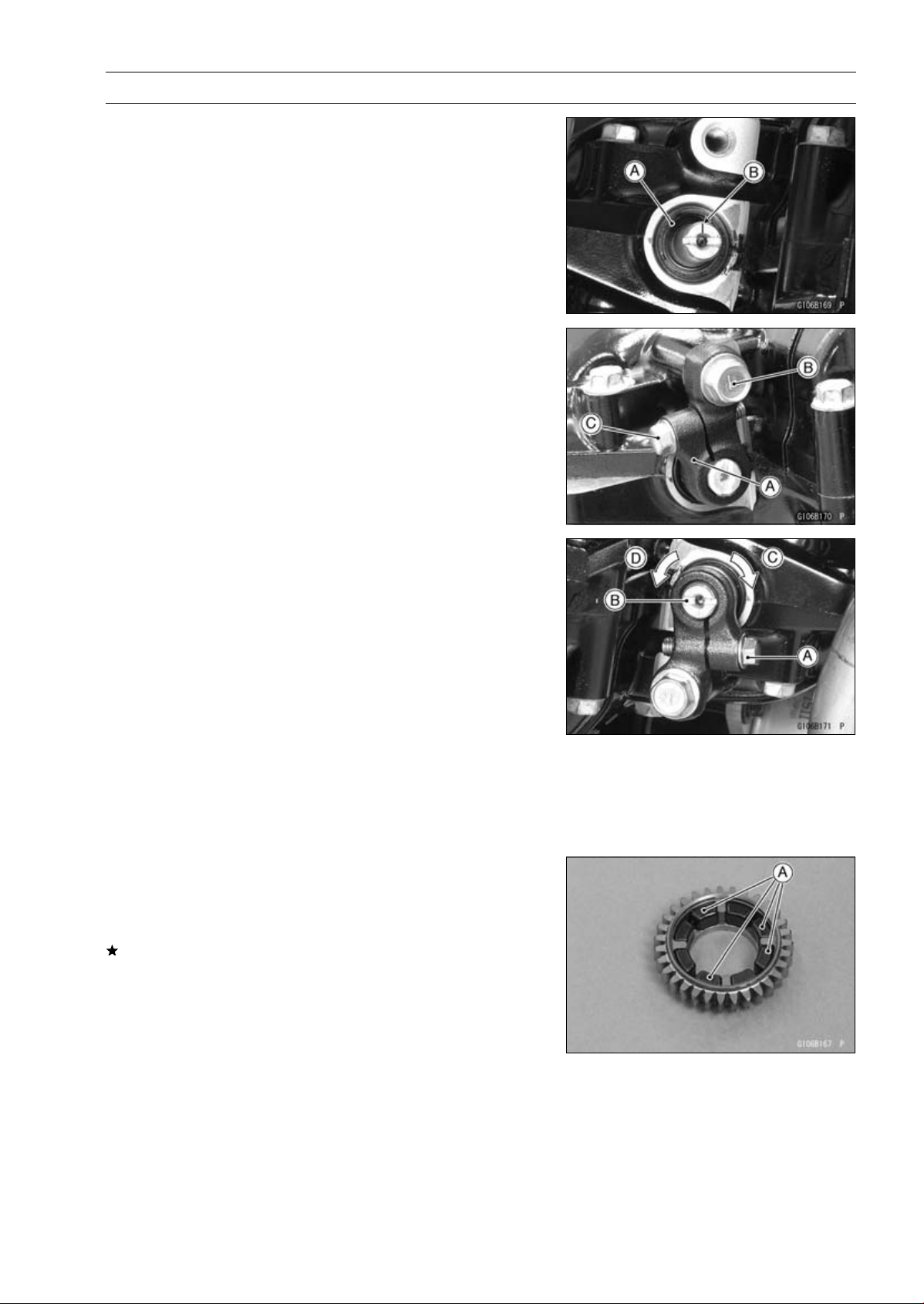
CRANKSHAFT/TRANSMISSION 9-27
Balancer
•
Assemble the crankcase (see Crankcase Assembly).
•
Fill the oil seal lips with grease.
•
Install the new oil seal [A] so that its surface is flush with
the surface of the crankcase.
•
Turn the balancer shaft so that its mark [B] faces down-
ward.
•
Install the balancer shaft lever [A].
•
Apply a non-parmanent locking agent to the threads of
the balancer shaft clamp lever bolt [B].
•
Tighten:
Torque - Balancer Shaft Clamp Lever Bolt: 25 N·m (2.5
kgf·m, 18 ft·lb)
Balancer Shaft Clamp Bolt [C]: 9.8 N·m (1.0 kgf·m,
87 in·lb)
Balancer Adjustment
•
Remove the lower fairing (see Lower Fairing Removal in
the Frame chapter).
•
Start the engine and warm it up thoroughly.
•
Adjust the balancer gear backlash with the engine idling.
The amount of backlash can be changed by turning the
balancer shaft which has eccentric journals.
○
Start the engine and let it idle.
○
Loosen the clamp bolt [A] and turn the balancer shaft [B]
clockwise [C] until the balancer gear makes a whining
sound.
○
Turn the shaft counterclockwise [D] until the balancer gear
whining sound disappears and tighten the clamp bolt.
Torque - Balancer Shaft Clamp Bolts: 9.8 N·m (1.0 kgf·m,
87 in·lb)
Balancer Damper Inspection
•
Remove the balancer and disassemble the weight and
gear assembly.
•
Visually inspect the rubber dampers [A].
If they appear damaged or deteriorated, replace them.
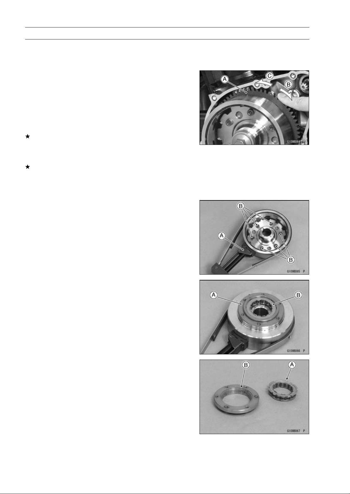
9-28 CRANKSHAFT/TRANSMISSION
Starter Motor Clutch
Starter Motor Clutch Removal/Installation
•
Refer to the Alternator Rotor Removal/Installation in the
Electrical System chapter.
Starter Motor Clutch Inspection
•
Remove:
Alternator Cover (see Alternator Cover Removal in the
Electrical System chapter)
Starter Idle Gear and Shaft
•
Turn the starter motor clutch gear [A] by hand. The starter
motor clutch gear should turn clockwise [B] freely, but
should not turn counterclockwise [C].
If the starter motor clutch does not operate as it should or
if it makes noise, go to the next step.
•
Disassemble the starter motor clutch, and visually inspect
the clutch parts.
If there is any worn or damaged part, replace it.
NOTE
○
Examine the starter motor clutch gear as well. Replace
it if it worn or damaged.
Starter Motor Clutch Disassembly
•
Remove:
Alternator Rotor (see Alternator Rotor Removal in the
Electrical System chapter)
•
Hold the alternator rotor with the flywheel holder [A].
Special Tool - Flywheel Holder: 57001-1313
•
Remove the starter motor clutch bolts [B].
•
Remove:
Starter Motor Clutch Housing [A]
Starter Motor Clutch [B]
Starter Motor Clutch Assembly
•
Install the starter motor clutch to the housing so that the
flange [A] fit to the housing groove [B].
•
Apply a non-permanent locking agent to the threads of
the starter motor clutch bolts and tighten them.
Torque - Starter Motor Clutch Bolts: 12 N·m (1.2 kgf·m, 106
in·lb)
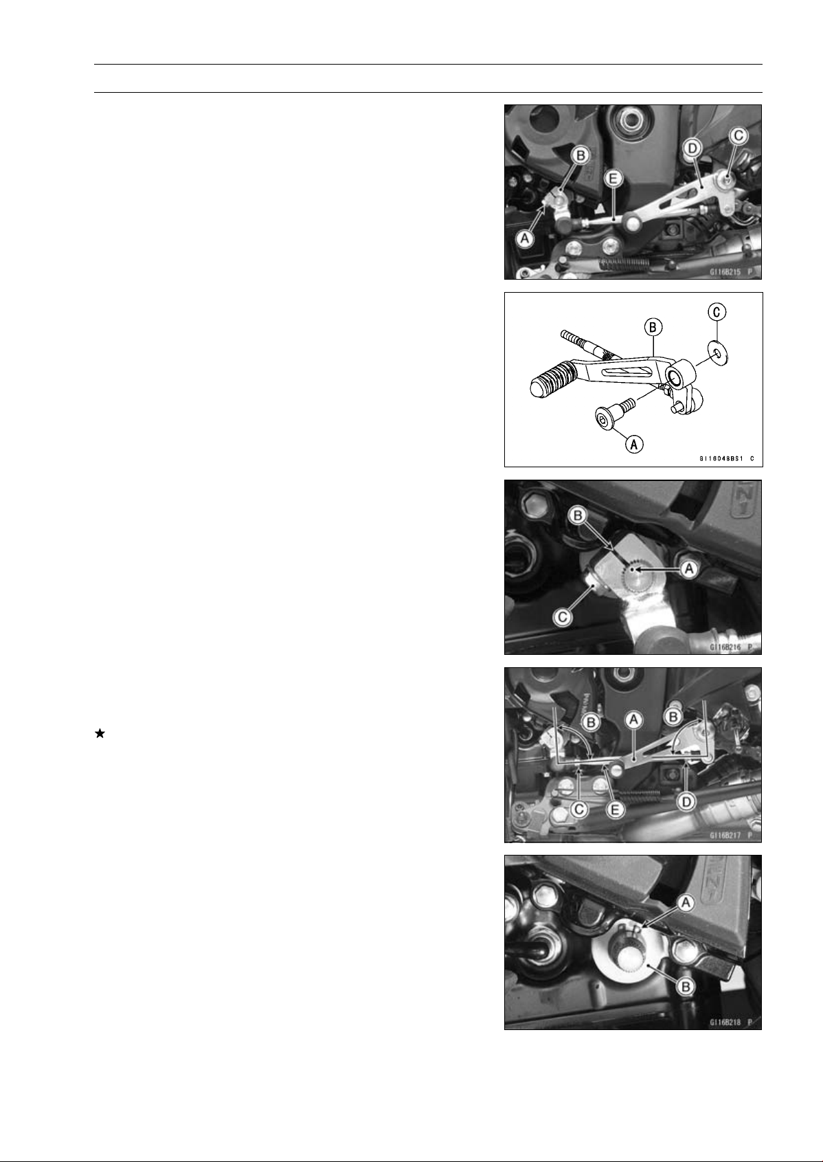
CRANKSHAFT/TRANSMISSION 9-29
External Shift Mechanism
Shift Pedal Removal
•
Remove:
Shift Lever Bolt [A]
Shift Lever [B]
Shift Pedal Mounting Bolt [C]
Shift Pedal [D] with Tie-rod [E]
Shift Pedal Installation
•
Tighten:
Torque - Shift Pedal Mounting Bolt [A]: 25 N·m (2.5 kgf·m,
18 ft·lb)
Shift Pedal [B]
Washer [C]
•
Align the punch mark [A] on the shift shaft with the slit [B]
of the shift lever.
•
Tighten the shift lever bolt [C].
•
After installation, confirm that the shift pedal [A] is posi-
tioned as shown in the figure.
About 90° [B]
If the pedal position is different, adjust it as follows.
○
To adjust the pedal position, loosen the front locknut [C]
(left-hand threads) and rear locknut [D], and then turn the
tie-rod [E].
External Shift Mechanism Removal
•
Remove:
Shift Lever (see Shift Pedal Removal)
Circlip [A]
Washer [B]
Clutch (see Clutch Removal in the Clutch chapter)
Special Tool - Outside Circlip Pliers: 57001-144
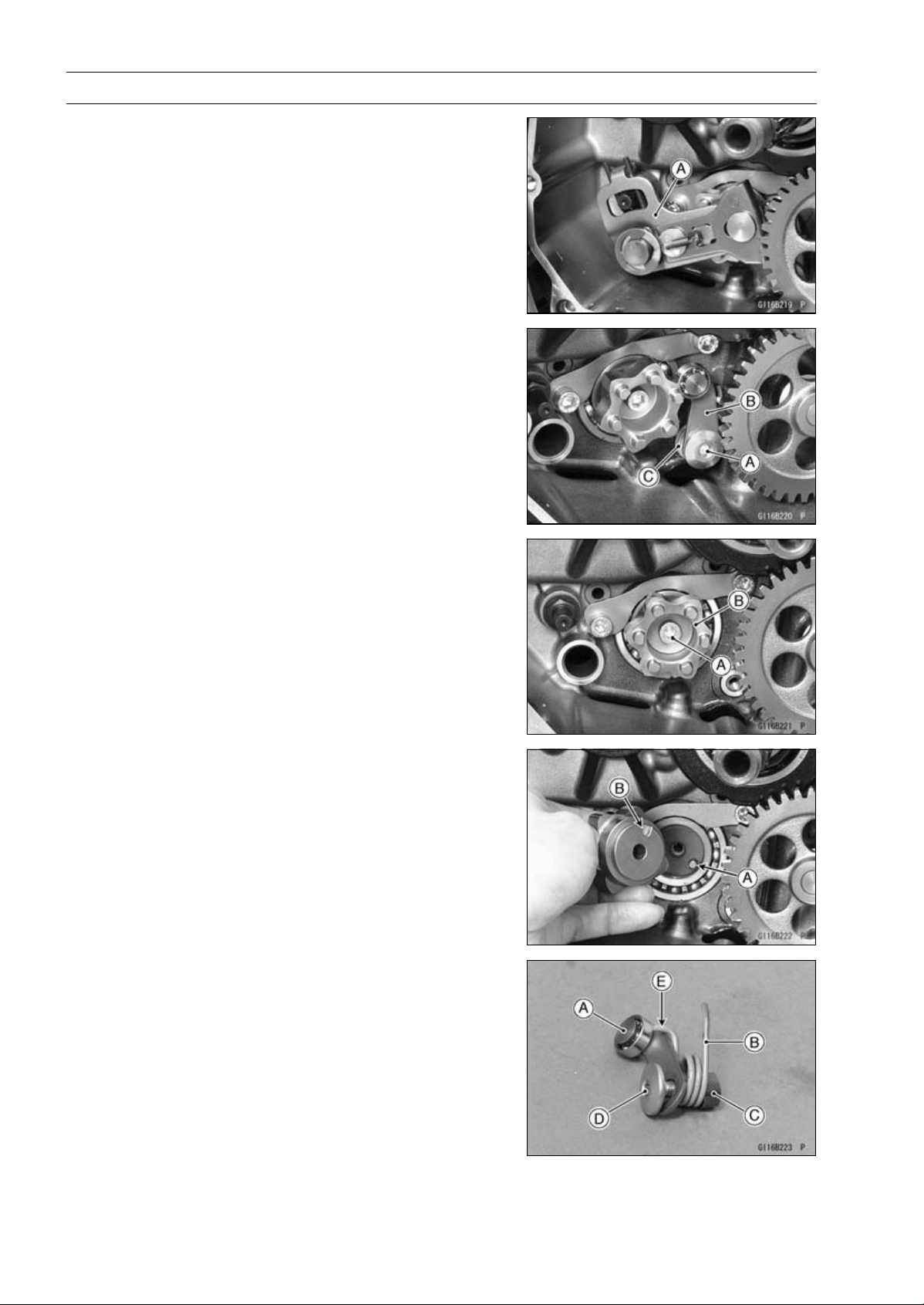
9-30 CRANKSHAFT/TRANSMISSION
External Shift Mechanism
•
Pull out the shift shaft assembly [A].
•
Remove:
Gear Positioning Lever Bolt [A]
Gear Positioning Lever [B]
Collar and Spring [C]
•
Remove:
Shift Drum Cam Bolt [A]
Shift Drum Cam [B]
External Shift Mechanism Installation
•
Be sure to install the dowel pin [A].
•
Align the dowel pin with the hollow [B] of the shift drum
cam.
•
Apply a non-permanent locking agent to the threads of
the shift drum cam bolt, and tighten it.
Torque - Shift Drum Cam Bolt: 12 N·m (1.2 kgf·m, 106 in·lb)
•
Assemble the following parts as shown.
[A] Gear Positioning Lever
[B] Spring
[C] Collar
[D] Gear Positioning Lever Bolt
○
Hang the spring end [E] to the gear positioning lever.
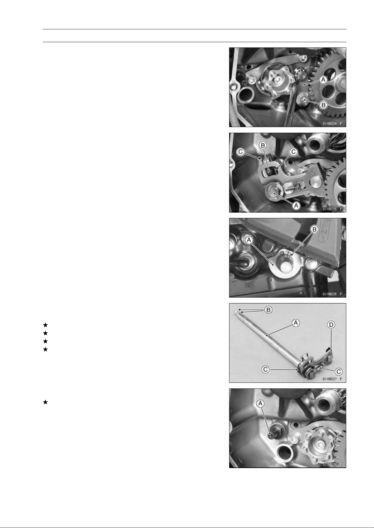
CRANKSHAFT/TRANSMISSION 9-31
External Shift Mechanism
•
While prying the gear positioning lever [A], tighten the
gear positioning lever bolt [B].
Torque - Gear Positioning Lever Bolt: 12 N·m (1.2 kgf·m,
106 in·lb)
•
Install the shift shaft [A] so that the return spring pin [A]
fits between the spring [C].
•
Install the washer [A].
•
Replace the circlip [B] with a new one, and install it.
Special Tool - Out side Circlip Pliers: 57001-144
External Shift Mechanism Inspection
•
Examine the shift shaft [A] for any damage.
If the shaft is bent, straighten or replace it.
If the serration [B] are damaged, replace the shaft.
If the springs [C] are damaged in any way, replace them.
If the shift mechanism arm [D] is damaged in any way,
replace the shift shaft.
•
Check the return spring pin [A] is not loose.
If it is loose, unscrew it, apply a non-permanent locking
agent to the threads, and tighten it.
Torque - Shift Shaft Return Spring Pin: 39 N·m (4.0 kgf·m,
29 ft·lb)
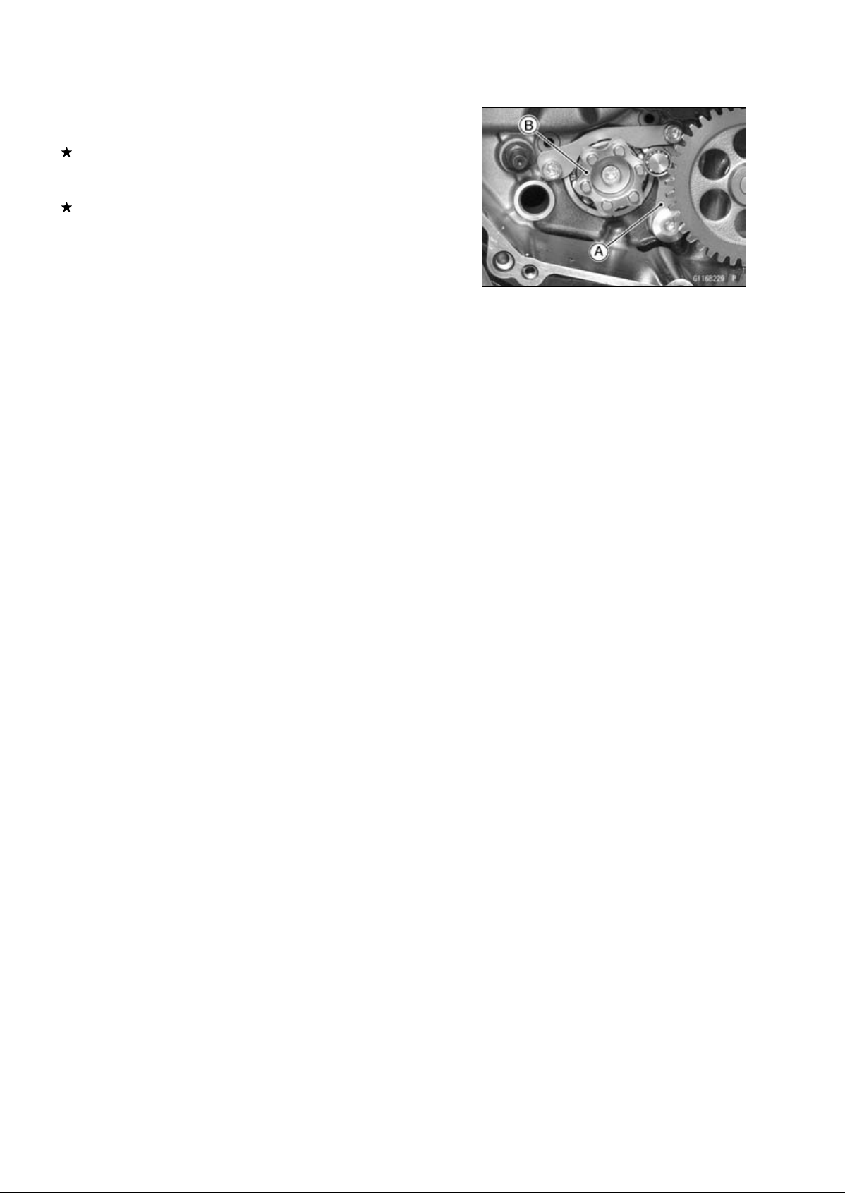
9-32 CRANKSHAFT/TRANSMISSION
External Shift Mechanism
•
Check the gear positioning lever [A] and its spring for
breaks or distortion.
If the lever or spring are damaged in any way, replace
them.
•
Visually inspect the shift drum cam [B].
If it is badly worn or shows any damage, replace it.

CRANKSHAFT/TRANSMISSION 9-33
Transmission
Transmission Shaft Removal
•
Split the crankcase (see Crankcase Splitting).
•
Remove the drive shaft [A] and output shaft [B].
Transmission Shaft Installation
•
Check to see that the set pins [A] and set rings [B] are in
place.
•
Install the drive shaft and output shaft into the upper
crankcase half.
•
Apply engine oil to the bearings.
○
The bearing set pins and rings must match properly with
the holes or grooves in the bearing outer races. When
they are properly matched, there is no clearance [A] be-
tween the crankcase and the bearing outer races.
•
Assemble the crankcase (see Crankcase Assembly).
•
Using a high flash-point solvent, clean off any oil or dirt
from the outer circumference of the oil seal [A] and its
matching surfaces of the crankcases. Wipe the solvent
with a clean cloth.
•
Apply high-temperature grease to the oil seal lips.
•
Insert the collar [B] into the oil seal.
•
Press in the oil seal into the crankcase so that the surface
of the oil seal is flush with the surface [C] of the crankcase.
Transmission Shaft Disassembly
•
Remove the transmission shafts (see Transmission Shaft
Removal).
•
Remove the circlips, and disassemble the transmission
shafts.
Special Tool - Outside Circlip Pliers: 57001-144
•
The 5th gear [A] on the output shaft has three steel balls
assembled into it for the positive neutral finder mecha-
nism. Remove the 5th gear.
○
Set the output shaft in a vertical position holding the 3rd
gear [B].
○
Spin the 5th gear quickly [C] and pull it off upward.
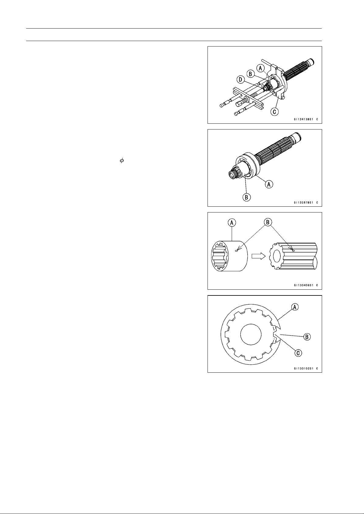
9-34 CRANKSHAFT/TRANSMISSION
Transmission
•
Remove the ball bearing [A] from each shafts.
Special Tools - Bearing Puller [C]: 57001-135
Bearing Puller Adapter [D]: 57001-317
•
Discard the bearing.
○
For output shaft, remove the collar [B] together with the
ball bearing.
Transmission Shaft Assembly
•
Install the new ball bearing [A] and collar [B] (output shaft)
on the each shaft, using the bearing driver.
Spacial Tool - Bearing Driver,
32: 57001-382
•
Apply engine oil to the bushings, ball bearings and shafts.
•
Install the gear bushings [A] on the shaft with their holes
[B] aligned.
•
Replace any circlips removed with new ones.
•
Install the circlips [A] so that the opening [B] is aligned
withasplinegroove[C].
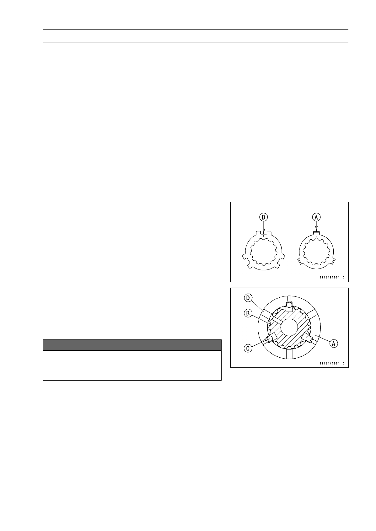
CRANKSHAFT/TRANSMISSION 9-35
Transmission
•
The drive shaft gears can be recognized by size: the gear
with the smallest diameter is 1st gear, and the largest one
is 6th gear. Be sure that all parts are put back in the cor-
rect sequence and all circlips and washers are properly in
place.
•
Install the 3rd/4th gear onto the drive shaft with their oil
holes aligned.
•
Install the 6th gear bushing onto the drive shaft with their
oil holes aligned.
•
The output shaft gears can be recognized by size: the
gear with the largest diameter is 1st gear, and the small-
est one is 6th gear. Be sure that all parts are put back
in the correct sequence and all circlips and washers are
properly in place.
•
Install the 5th and 6th gears onto the output shaft with
their oil holes aligned.
•
Install the 3rd/4th gear bushings onto the output shaft with
their oil holes aligned.
NOTE
○
When the toothed washers are assembled onto the out-
put shaft, note the following.
○
When the tangs [A] of the toothed washer shall be as-
sembled, they should be installed into the notch [B] of
the toothed washer (see Page 9-36).
•
Fit the steel balls into the 5th gear holes in the output
shaft, aligning oil hole as shown.
5th Gear [A]
Output Shaft [B]
Steel Balls [C]
Oil Hole [D]
NOTICE
Do not apply grease to the balls to hold them in
place. This will cause the positive neutral finder
mechanism to malfunction.
○
After assembling the 5th gear with steel balls in place on
the output shaft, check the ball-locking effect that the 5th
gear doesn’t come out of the output shaft when moving it
up and down by hand.
•
Check that each gear spins or slides freely on the trans-
mission shafts without binding after assembly.
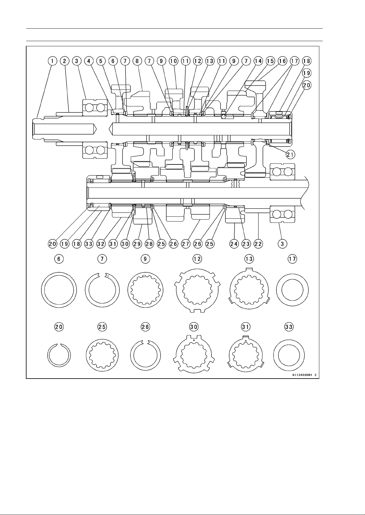
9-36 CRANKSHAFT/TRANSMISSION
Transmission
CRANKSHAFT/TRANSMISSION 9-37
Transmission
1. Output Shaft
2. Collar
3. Bearing
4. Bushing
5. 2nd Gear (39 T)
6. Washer (
34 × 28.1)
7. Circlips (
33 × 25.9)
8. Top Gear (25 T)
9. Toothed Washer (
34)
10. 4th/3rd Gear (25 T/24 T)
11. Bushing
12. Toothed Washer (
40.5)
13. Toothed Washer (
37)
14. Steel Balls
15. 5th Gear (26 T)
16. Low Gear (39 T)
17. Washers (
31 × 20.5)
18. Races
19. Needle Bearings
20. Circlips (
22.2 × 18.7)
21. Needle Bearing
22. Low Gear (15 T) (Drive Shaft)
23. Bushing
24. 5th Gear (21 T)
25. Toothed Washer (
31)
26. Circlip (
29 × 22.6)
27. 3rd/4th Gear (15 T/18 T)
28. Bushing
29. Top Gear (22 T)
30. Toothed Washer (
34.2)
31. Toothed Washer (
32)
32. 2nd Gear (20 T)
33. Washer (
30 × 20.5)
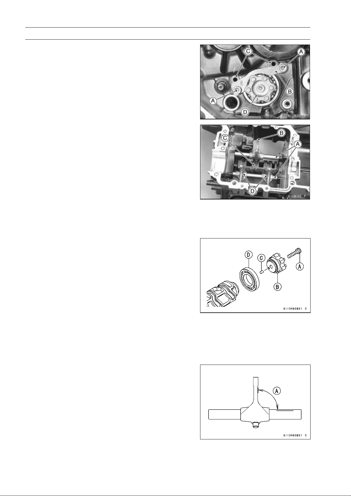
9-38 CRANKSHAFT/TRANSMISSION
Transmission
Shift Drum and Fork Removal
•
Remove:
Lower Crankcase Half (see Crankcase Splitting)
Transmission Shafts (see Transmission Shaft Removal)
Gear Positioning Lever (see External Shift Mechanism
Removal)
Bolts [A]
Shift Drum Bearing Holder [B]
•
Pull out the shift rods [C], and take off the shift forks.
•
Pull out the shift drum [D].
Shift Drum and Fork Installation
•
Apply engine oil to the shift drum, forks and rods.
•
Install the shift rods [A], noting the groove position.
○
The rods are identical.
○
Position the one with shortest ears [B] on the drive shaft
and place the pin in the center groove in the shift drum
[C].
○
The two forks [D] on the output shaft are identical.
•
Install the forks so that its “0061” and “0062” side faces
engine left side.
•
Apply a non-permanent locking agent to the threads of
the shift drum bearing holder bolts, and tighten them.
Torque - Shift Drum Bearing Holder Bolts: 12 N·m (1.2
kgf·m, 106 in·lb)
Shift Drum Disassembly
•
Remove the shift drum (see Shift Drum and Fork Re-
moval).
•
While holding the shift drum with a vise, remove the shift
drum cam bolt [A].
•
Remove:
Shift Drum Cam [B]
Dowel Pin [C]
Bearing [D]
Shift Drum Assembly
•
Be sure to install the dowel pin.
•
Apply a non-permanent locking agent to the threads of
the shift drum bearing holder bolt, and tighten it.
Torque - Shift Drum Cam Bolt: 12 N·m (1.2 kgf·m, 106 in·lb)
Shift Fork Bending Inspection
•
Visually inspect the shift forks, and replace any fork that is
bent. A bent fork could cause difficulty in shifting, or allow
the transmission to jump out of gear when under power.
90° [A]
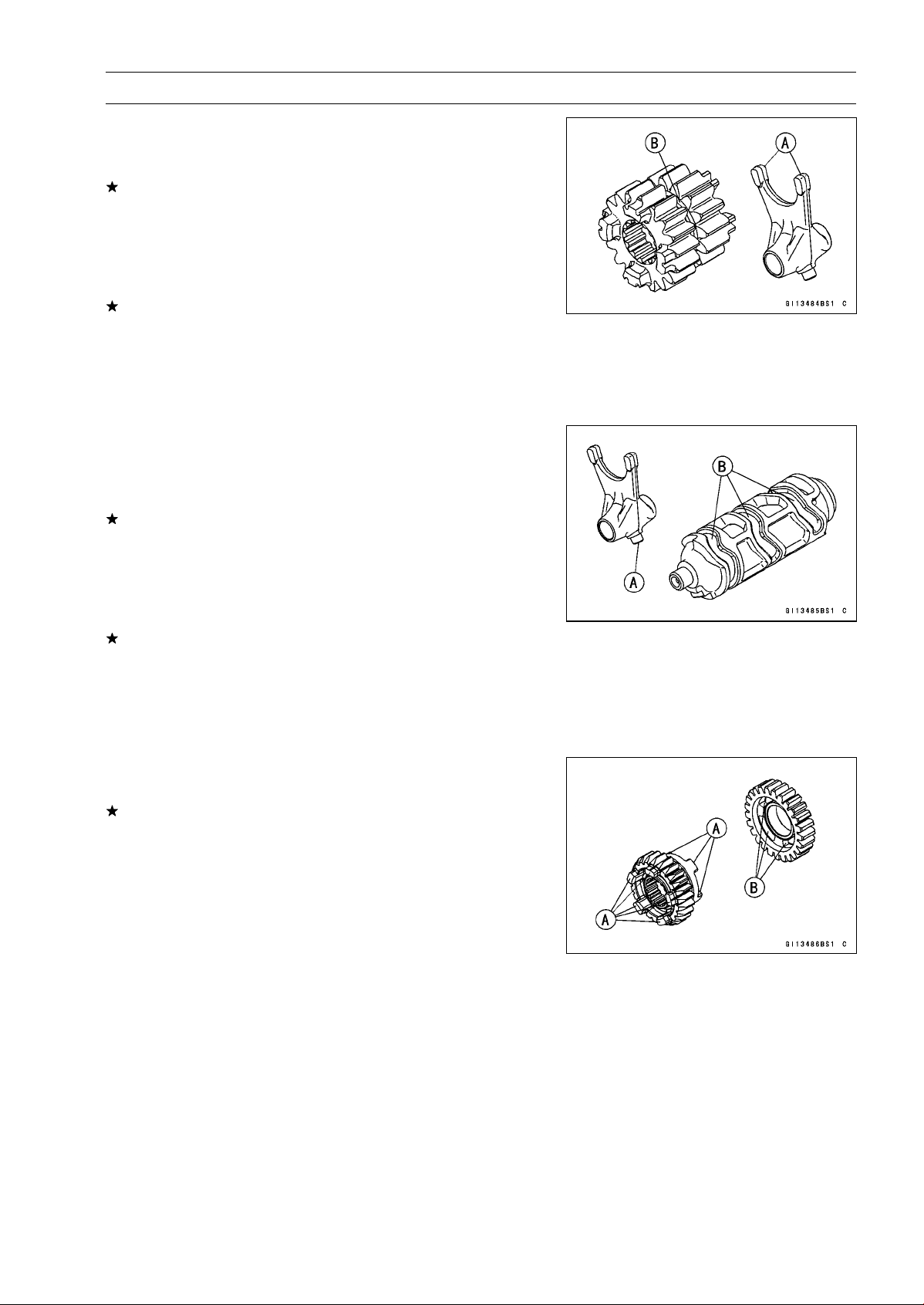
CRANKSHAFT/TRANSMISSION 9-39
Transmission
Shift Fork/Gear Groove Wear Inspection
•
Measure the thickness of the shift fork ears [A], and mea-
sure the width of the gear grooves [B].
If the thickness of a shift fork ear is less than the service
limit, the shift fork must be replaced.
Shift Fork Ear Thickness
Standard: 5.9
∼ 6.0 mm (0.232 ∼ 0.236 in.)
Service Limit: 5.8 mm (0.228 in.)
If the gear groove is worn over the service limit, the gear
must be replaced.
Gear Groove Width
Standard: 6.05
∼ 6.15 mm (0.238 ∼ 0.242 in.)
Service Limit: 6.25 mm (0.246 in.)
Shift Fork Guide Pin/Drum Groove Wear
Inspection
•
Measure the diameter of each shift fork guide pin [A], and
measure the width of each shift drum groove [B].
If the guide pin on any shift fork is less than the service
limit, the fork must be replaced.
Shift Fork Guide Pin Diameter
Standard: 6.9
∼ 7.0 mm (0.272 ∼ 0.276 in.)
Service Limit: 6.8 mm (0.268 in.)
If any shift drum groove is worn over the service limit, the
drum must be replaced.
Shift Drum Groove Width
Standard: 7.05
∼ 7.20 mm (0.278 ∼ 0.283 in.)
Service Limit: 7.3 mm (0.287 in.)
Gear Dog and Gear Dog Hole Damage Inspection
•
Visually inspect the gear dogs [A] and gear dog holes [B].
Replace any damaged gears or gears with excessively
worn dogs or dog holes.
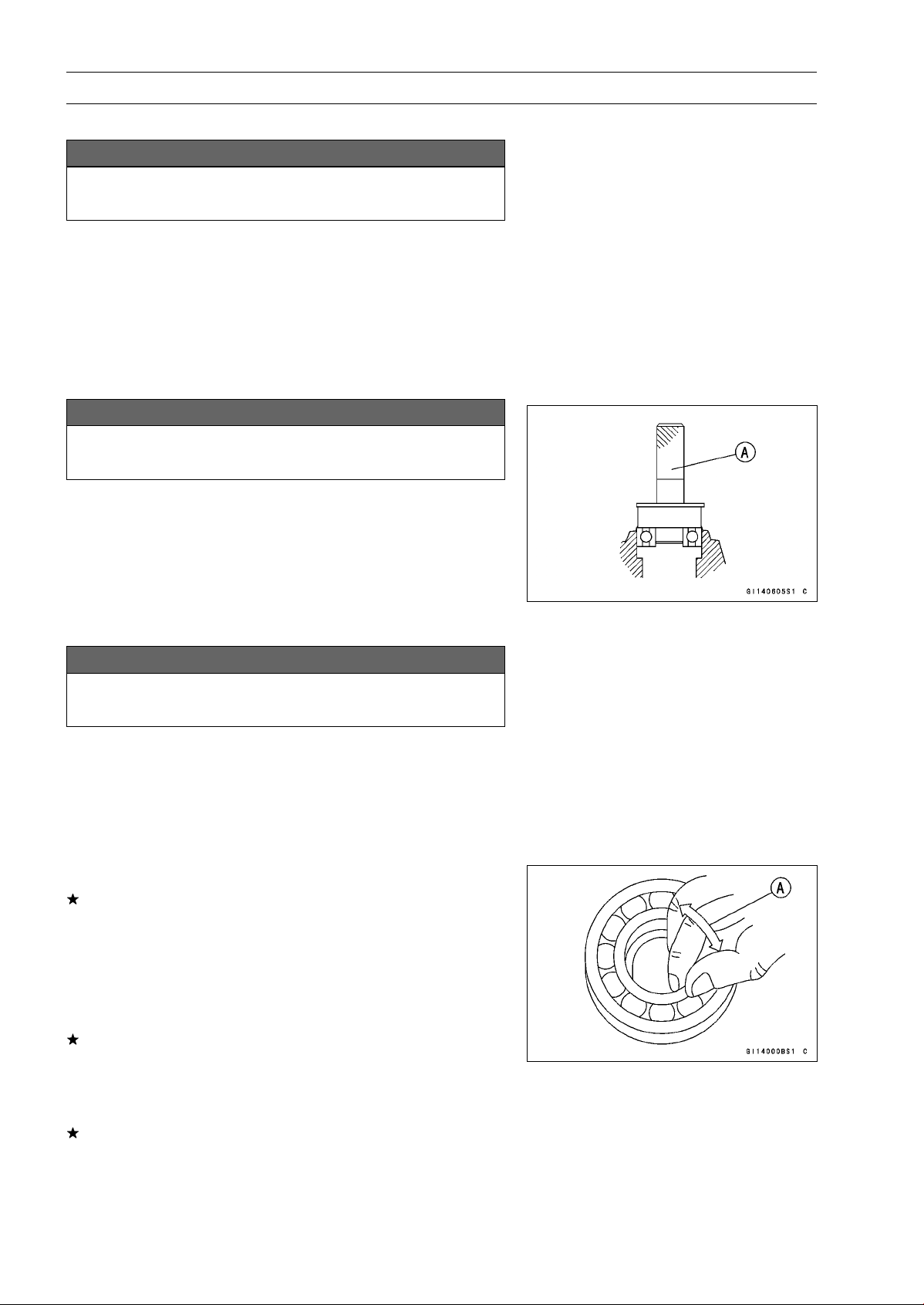
9-40 CRANKSHAFT/TRANSMISSION
Ball Bearing, Needle Bearing, and Oil Seal
Ball and Needle Bearing Replacement
NOTICE
Do not remove the ball or needle bearings unless it
is necessary. Removal may damage them.
•
Using a press or puller, remove the ball bearing and/or
needle bearings.
NOTE
○
In the absence of the above mentioned tools, satisfac-
tory results may be obtained by heating the case to ap-
proximately 93°C (200°F) max., and tapping the bearing
in or out.
NOTICE
Do not heat the case with a torch. This will warp the
case. Soak the case in oil and heat the oil.
•
Using a press and the bearing driver set [A], install the
new ball bearing until it stops at the bottom of its housing.
○
The new needle bearings must be pressed into the
crankcase so that the end is flush with the end of the
hole.
Special Tool - Bearing Driver Set: 57001-1129
Ball and Needle Bearing Wear
NOTICE
Do not remove the bearings for inspection. Re-
moval may damage them.
•
Check the ball bearings.
○
Since the ball bearings are made to extremely close toler-
ances, the wear must be judged by feel rather than mea-
surement. Clean each bearing in a high flash-point sol-
vent, dry it (do not spin the bearing while it is dry), and oil
it with engine oil.
○
Spin [A] the bearing by hand to check its condition.
If the bearing is noisy, does not spin smoothly, or has any
rough spots, replace it.
•
Check the needle bearings.
○
The rollers in a needle bearing normally wear very little,
and wear is difficult to measure. Instead of measuring,
inspect the bearing for abrasion, color change, or other
damage.
If there is any doubt as to the condition of a needle bear-
ing, replace it.
Oil Seal Inspection
•
Inspect the oil seals.
Replace it if the lips are misshapen, discolored (indicating
that the rubber has deteriorated), hardened or otherwise
damaged.

WHEELS/TIRES 10-1
10
Wheels/Tires
Table of Contents
Exploded View........................................................................................................................ 10-2
Specifications ......................................................................................................................... 10-4
Special Tools .......................................................................................................................... 10-6
Wheels (Rims)........................................................................................................................ 10-7
Front Wheel Removal ....................................................................................................... 10-7
Front Wheel Installation .................................................................................................... 10-7
Rear Wheel Removal........................................................................................................ 10-8
Rear Wheel Installation..................................................................................................... 10-10
Wheel Inspection .............................................................................................................. 10-11
Axle Inspection..................................................................................................................10-11
Balance Inspection............................................................................................................ 10-12
Balance Adjustment.......................................................................................................... 10-12
Balance Weight Removal.................................................................................................. 10-12
Balance Weight Installation............................................................................................... 10-12
Tires........................................................................................................................................ 10-14
Air Pressure Inspection/Adjustment.................................................................................. 10-14
Tire Inspection .................................................................................................................. 10-14
Tire Removal..................................................................................................................... 10-14
Tire Installation.................................................................................................................. 10-14
Tire Repair ........................................................................................................................ 10-16
Hub Bearing............................................................................................................................ 10-17
Hub Bearing Removal....................................................................................................... 10-17
Hub Bearing Installation.................................................................................................... 10-17
Hub Bearing Inspection..................................................................................................... 10-18
Hub Bearing Lubrication ................................................................................................... 10-18
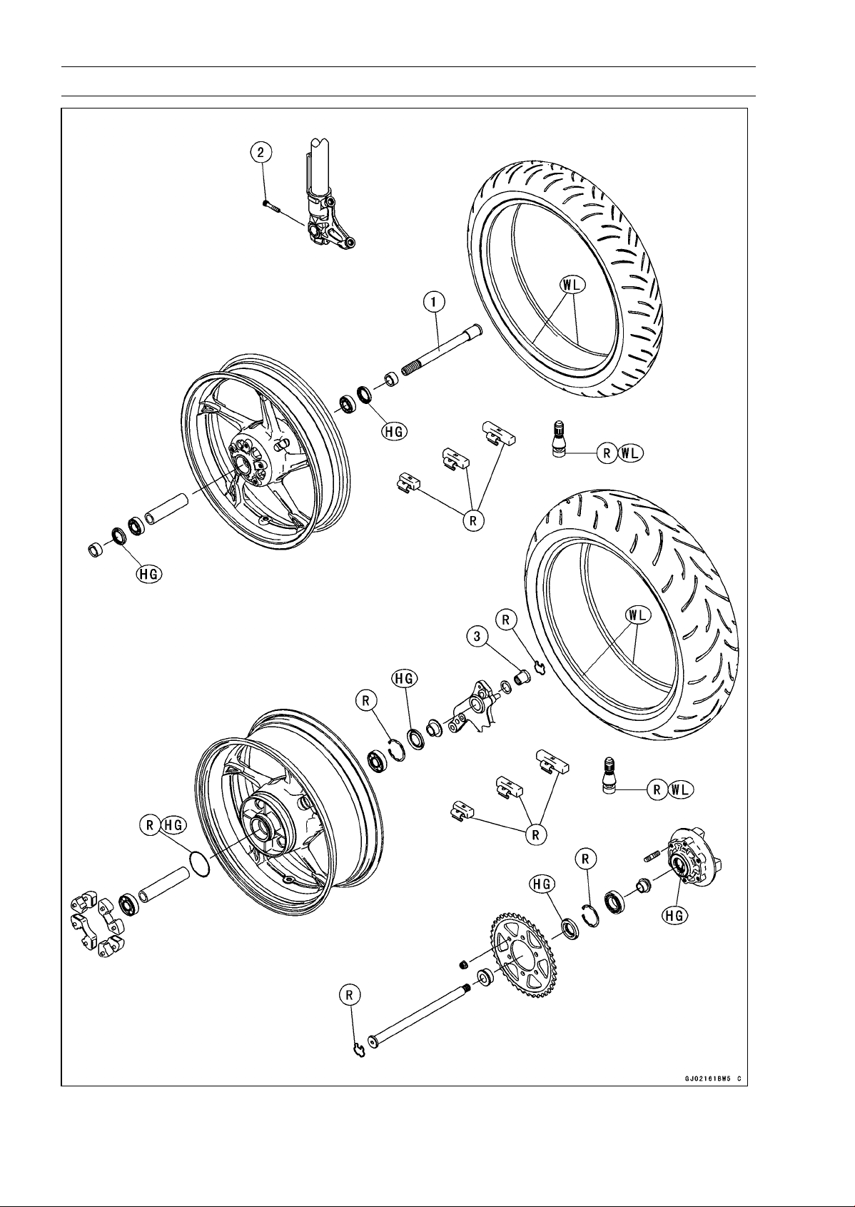
10-2 WHEELS/TIRES
Exploded View

WHEELS/TIRES 10-3
Exploded View
Torque
No. Fastener
N·m
kgf·m ft·lb
Remarks
1 Front Axle 108 11.0 79.7
2 Front Axle Clamp Bolt 20 2.0 15
3 Rear Axle Nut 98 10 72
HG: Apply high-temperature grease.
R: Replacement Parts
WL: Apply soap and water solution or rubber lubricant.

10-4 WHEELS/TIRES
Specifications
Item Standard Service Limit
Wheels (Rims)
Rim Runout:
Axial
TIR 0.5 mm (0.02 in.) or less TIR 1.0 mm (0.04 in.)
Radial
TIR 0.8 mm (0.03 in.) or less TIR 1.0 mm (0.04 in.)
Axle Runout/100 mm
(3.94 in.)
TIR 0.1 mm (0.004 in.) o
rless
TIR 0.2 mm (0.008 in.)
Wheel Balance 10 g (0.35 oz.) or less –––
Balance Weights 10 g (0.35 oz.), 20 g (0.71 oz.),
30 g (1.06 oz.)
–––
Rim Size:
Front
J17M/C × MT3.50
–––
Rear J17M/C × MT6.00 –––
Tires
Air Pressure (when
Cold):
Front Up to 180 kg (397 lb) load: 250 kPa
(2.5 kgf/cm², 36 psi)
–––
Rear
Up to 180 kg (397 lb) load: 290 kPa
(2.9 kgf/cm², 42 psi)
–––
Tread Depth:
Front
ZR1000D 4.0 mm (0.16 in.) 1 mm (0.04 in.)
ZR1000E 3.8 mm (0.15 in.) (AT, CH, DE) 1.6 mm (0.06 in.)
Rear
ZR1000D 5.5 mm (0.22 in.)
Up to 130 km/h (80 mph):
2 mm (0.08 in.)
ZR1000E
5.4 mm (0.21 in.)
Over 130 km/h (80 mph):
3 mm (0.12 in.)
Standard Tires: Make, Type Size
ZR1000D
Front DUNLOP, SPORTMAX D210F J 120/70 ZR17 M/C (58 W)
Rear DUNLOP, SPORTMAX D210 190/50 ZR17 M/C (73 W)
ZR1000E
Front PIRELLI, DIABLO ROSSO K 120/70 ZR17 M/C (58 W)
Rear PIRELLI, DIABLO ROSSO K 190/50 ZR17 M/C (73 W)
WHEELS/TIRES 10-5
Specifications
Item Standard Service Limit
Replacement Tires:
Make, Type Size
Front
BRIDGESTONE, BATTLAX BT003F
RACING STREET
120/70 ZR 17M/C (58W)
BRIDGESTONE, BATTLAX BT016F
HYPERSPORT
120/70 ZR 17M/C (58W)
BRIDGESTONE, BATTLAX BT023F 120/70 ZR 17M/C (58W)
Continental, ContiRaceAttack Street 120/70 ZR 17M/C (58W)
Continental, ContiRoadAttack 2 120/70 ZR 17M/C (58W)
DUNLOP, SPORTMAX ROADSMART 120/70 ZR 17M/C (58W)
METZELER, ROADTEC Z6
INTERACT
120/70 ZR 17M/C (58W)
METZELER, SPORTEC M5
INTERACT
120/70 ZR 17M/C (58W)
MICHELIN, PILOT POWER 2CT 120/70 ZR 17M/C (58W)
MICHELIN, POWER PURE 120/70 ZR 17M/C (58W)
PIRELLI, ANGEL ST FRONT 120/70 ZR 17M/C (58W)
Rear BRIDGESTONE, BATTLAX BT003R
RACING STREET
190/50 ZR 17M/C (73W)
BRIDGESTONE, BATTLAX BT016R
HYPERSPORT
190/50 ZR 17M/C (73W)
BRIDGESTONE, BATTLAX BT023R 190/50 ZR 17M/C (73W)
Continental, ContiRaceAttack Street 190/50 ZR 17M/C (73W)
Continental, ContiRoadAttack 2 190/50 ZR 17M/C (73W)
DUNLOP, SPORTMAX ROADSMART 190/50 ZR 17M/C (73W)
METZELER, ROADTEC Z6
INTERACT
190/50 ZR 17M/C (73W)
METZELER, SPORTEC M5
INTERACT
190/50 ZR 17M/C (73W)
MICHELIN, PILOT POWER 2CT 190/50 ZR 17M/C (73W)
MICHELIN, POWER PURE 190/50 ZR 17M/C (73W)
PIRELLI, ANGEL ST 190/50 ZR 17M/C (73W)
WARNING
Some replacement tires may adversely affect handling and cause an accident resulting in
serious injury or death. To ensure proper handling and stability, use only the recommended
standard tires for replacement, inflated to the standard pressure.
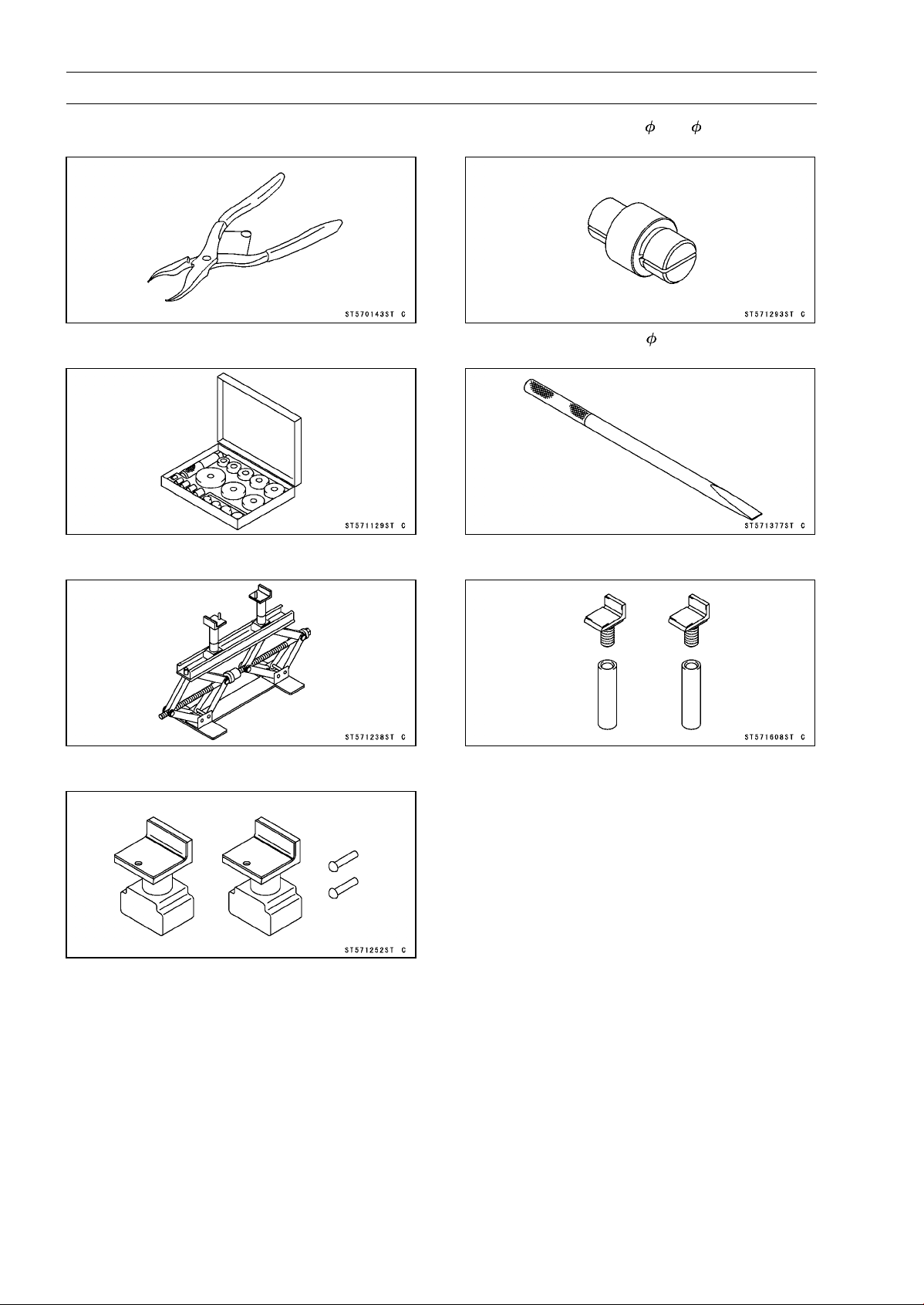
10-6 WHEELS/TIRES
Special Tools
Inside Circlip Pliers:
57001-143
Bearing Driver Set:
57001-1129
Jack:
57001-1238
Attachment Jack:
57001-1252
Bearing Remover Head, 20 × 22:
57001-1293
Bearing Remover Shaft, 13:
57001-1377
Jack Attachment:
57001-1608
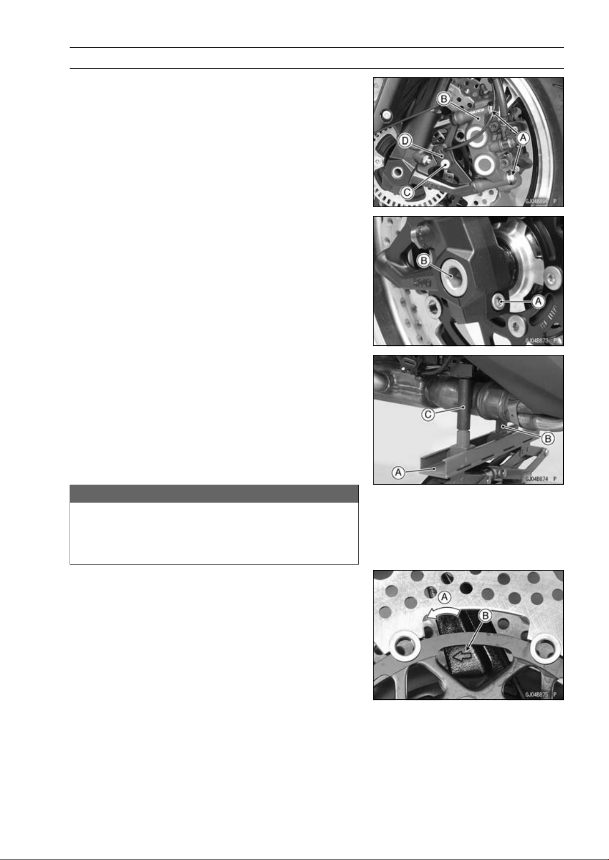
WHEELS/TIRES 10-7
Wheels (Rims)
Front Wheel Removal
•
Remove:
Front Caliper Mounting Bolts [A] (Both Sides)
Front Calipers [B] (Both Sides)
Rear Lower Fairing (see Rear Lower Fairing Removal in
the Frame chapter)
Front Fender (see Front Fender Removal in the Frame
chapter)
•
For the ABS equipped Models, remove the bolt [C] and
front wheel rotation sensor [D].
•
Loosen:
Front Axle Clamp Bolt [A] (Loosen)
Front Axle [B]
•
For the oxygen sensor equipped Models, remove the
oxygen sensor (see Oxygen Sensor Removal (Equipped
Models) in the Electrical System chapter).
•
Raise the front wheel off the ground.
Special Tools - Jack [A]: 57001-1238
Attachment Jack [B]: 57001-1252
Jack Attachment [C]: 57001-1608
•
Pull out the axle to the right and drop the front wheel out
of the forks.
NOTICE
Do not lay the wheel down on one of the discs. This
can damage or warp the disc. Place blocks un-
der the wheel so that the disc does not touch the
ground.
Front Wheel Installation
NOTE
○
The direction of the wheel rotation [A] is shown by an
arrow [B] on the wheel spoke.
•
Check the wheel rotation mark on the front wheel and
install it.
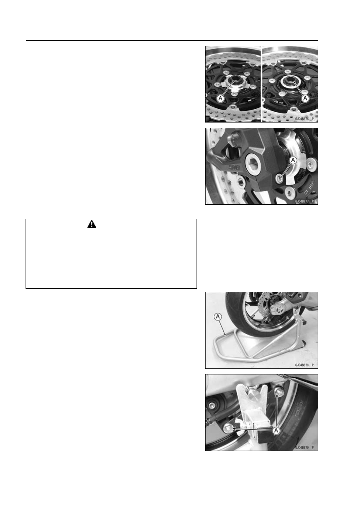
10-8 WHEELS/TIRES
Wheels (Rims)
•
Apply high-temperature grease to the grease seal lips.
•
Fit the collars [A] on the both sides of the hub.
○
The collars are identical.
•
Insert the front axle.
•
Tighten:
Torque - Front Axle: 108 N·m (11.0 kgf·m, 79.7 ft·lb)
•
Before tightening the axle clamp bolt [A] on the right front
fork leg, pump the front fork up and down 4 or 5 times to
allow the right front fork leg to seat on the front axle.
NOTE
○
Put a block in front of the front wheel to stop moving.
•
Tighten:
Torque - Front Axle Clamp Bolt: 20 N·m (2.0 kgf·m, 15 ft·lb)
•
Install the removed parts (see appropriate chapters).
•
Check the front brake effectiveness (see Brake Operation
Inspection in the Periodic Maintenance chapter).
WARNING
After servicing, it takes several applications of the
brake lever before the brake pads contact the disc,
which could result in increased stopping distance
and cause an accident resulting in injury or death.
Do not attempt to ride the motorcycle until a firm
brake lever is obtained by pumping the lever until
the pads are against the disc.
Rear Wheel Removal
•
Raise the rear wheel off the ground with the stand [A].
•
Loosen the torque link nuts [A] lightly for chain adjuster
turn easily.
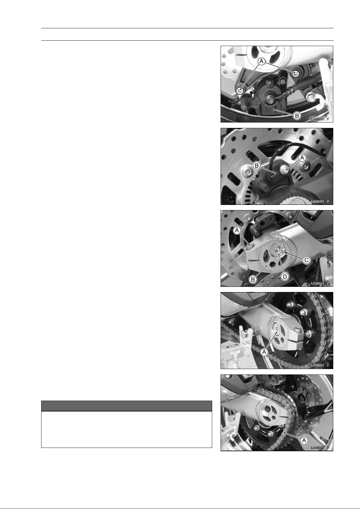
WHEELS/TIRES 10-9
Wheels (Rims)
•
Remove:
Rear Caliper Mounting Bolts [A]
Rear Caliper [B]
•
For ABS equipped Models, remove the bolt [A] and rear
wheel rotation sensor [B].
•
Loosen the chain adjuster clamp bolts [A] (Both Sides).
•
Turn the chain adjuster [B] to make the chain slack.
•
Remove:
Retaining Rings [C] (Both Sides)
Rear Axle Nut [D]
Washer
•
Remove:
Rear Axle [A] (from Left Side)
•
Remove the drive chain [A] from the rear sprocket toward
the left.
•
Move the rear wheel back and remove it.
NOTICE
Do not lay the wheel on the ground with the disc
facing down. This can damage or warp the disc.
Place blocks under the wheel so that the disc does
not touch the ground.
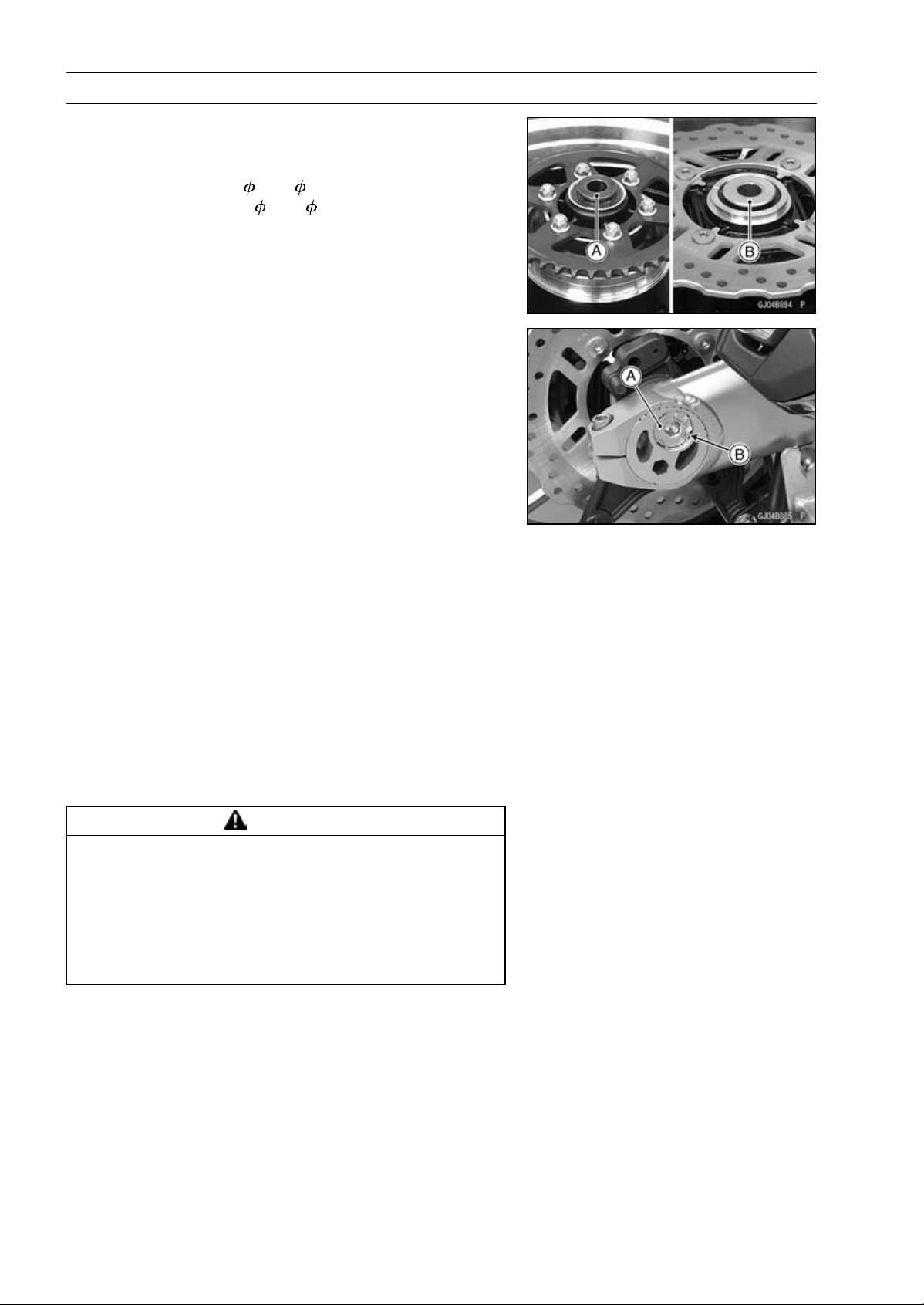
10-10 WHEELS/TIRES
Wheels (Rims)
Rear Wheel Installation
•
Apply high-temperature grease to the grease seal lips.
•
Fit the collars on the both sides of the hub.
Left Side Collar [A] (
40 × 35)
Right Side Collar [B] (
44 × 28)
•
Engage the drive chain with the rear sprocket.
•
Insert the axle from the left side of the wheel.
•
Align the hole of the brake holder with hole of the rear
wheel.
•
Install:
Washer
Rear Axle Nut [A]
•
Before tightening the rear axle nut, check that the scale
on the left and right adjusters set the same position.
•
Tighten:
Torque - Rear Axle Nut: 98 N·m (10 kgf·m, 72 ft·lb)
•
Replace the retaining rings [B] with new ones, and install
them.
•
Adjust the drive chain slack after installation (see Drive
Chain Slack Inspection in the Periodic Maintenance chap-
ter).
•
Tighten:
Torque - Torque Link Nuts: 34 N·m (3.5 kgf·m, 25 ft·lb)
•
Install the rear caliper (see Caliper Installation in the
Brakes chapter).
•
Check the rear brake effectiveness (see Brake Operation
Inspection in the Periodic Maintenance chapter).
WARNING
After servicing, it takes several applications of the
brake pedal before the brake pads contact the disc,
which could result in increased stopping distance
and cause an accident resulting in injury or death.
Do not attempt to ride the motorcycle until a firm
brake pedal is obtained by pumping the pedal until
the pads are against the disc.
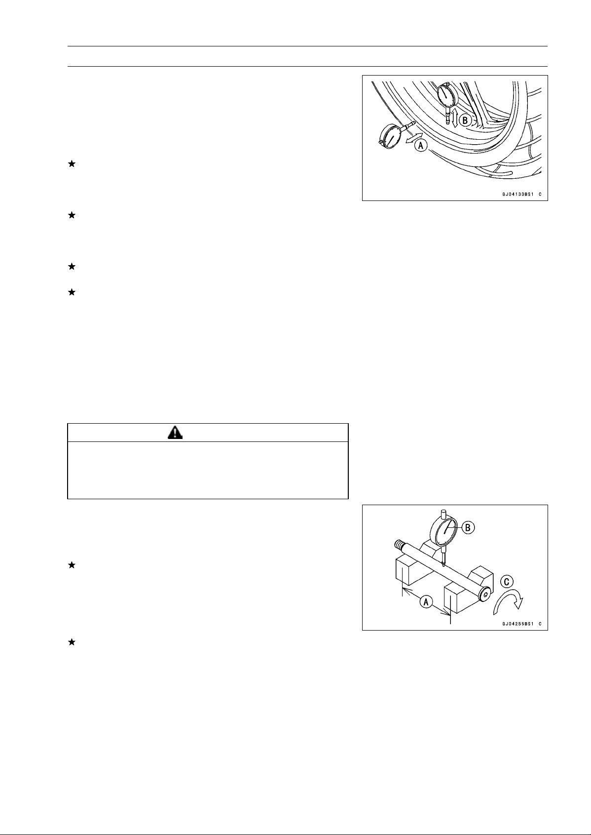
WHEELS/TIRES 10-11
Wheels (Rims)
Wheel Inspection
•
Raise the front/rear wheel off the ground.
Special Tools - Jack: 57001-1238
Jack Attachment: 57001-1608
Attachment Jack: 57001-1252
•
Spin the wheel lightly, and check for roughness or binding.
If roughness or binding is found, replace the hub bearings
(see Hub Bearing Removal/Installation).
•
Inspect the wheel for small cracks, dents, bending, or
warp.
If there is any damage to the wheel, replace the wheel.
•
Remove the wheel, and support it with the tire by the axle.
•
Measure the rim runout, axial [A] and radial [B], with a dial
gauge.
If rim runout exceeds the service limit, check the hub bear-
ings (see Hub Bearing Inspection).
If the problem is not due to the bearings, replace the
wheel.
Rim Runout (with tire installed)
Standard:
Axial
TIR 0.5 mm (0.02 in.) or less
Radial
TIR 0.8 mm (0.03 in.) or less
Service Limit:
Axial
TIR 1.0 mm (0.04 in.)
Radial
TIR 1.0 mm (0.04 in.)
WARNING
Damaged wheel parts may fail and cause an acci-
dent resulting in serious injury or death. Never at-
tempt to repair a damaged wheel part. If the wheel
part is damaged, it must be replaced with a new one.
Axle Inspection
•
Remove the front an
d rear axles (see Front/Rear Wheel
Removal).
•
Visually inspect the front and rear axle for damages.
If the axle is damaged or bent, replace it.
•
Place the axle in V blocks that are 100 mm (3.94 in.) [A]
apart, and set a dial gauge [B] on the axle at a point
halfway between the blocks. Turn [C] the axle to mea-
sure the runout. The difference between the highest and
lowest dial readings is the amount of runout.
If axle runout exceeds the service limit, replace the axle.
Axle Runout/100 mm (3.94 in.)
Standard: TIR 0.1 mm (0.004 in.) or less
Service Limit: TIR 0.2 mm (0.008 in.)
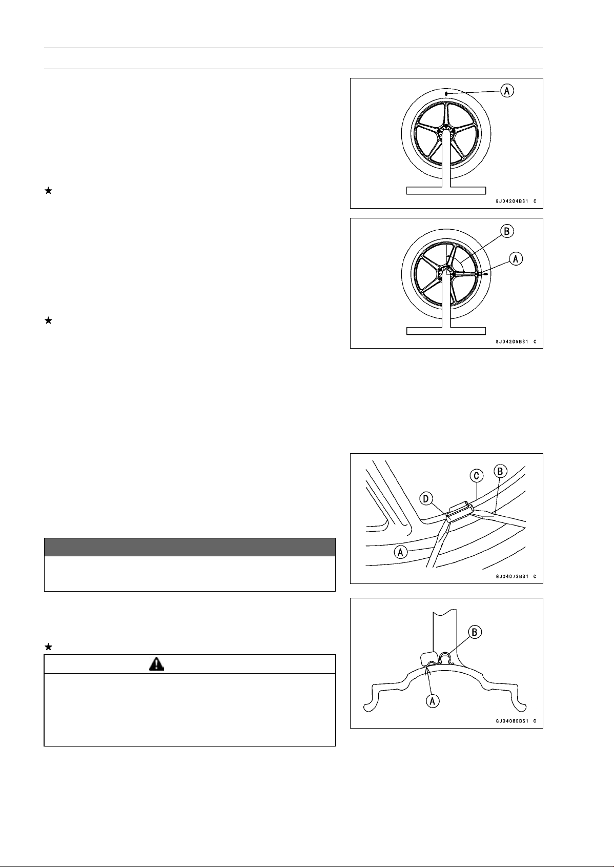
10-12 WHEELS/TIRES
Wheels (Rims)
Balance Inspection
•
Remove the front and rear wheels (see Front/Rear Wheel
Removal).
•
Support the wheel so that it can be spun freely.
•
Spin the wheel lightly, and mark [A] the wheel at the top
when the wheel stops.
○
Repeat this procedure several times. If the wheel stops
of its own accord in various positions, it is well balanced.
If the wheel always stops in one position, adjust the wheel
balance (see Balance Adjustment).
Balance Adjustment
•
If the wheel always stops in one position, provisionally
attach a balance weight [A] on the rim at the marking using
adhesive tape.
•
Rotate the wheel 1/4 turn [B], and see whether or not the
wheel stops in this position. If it does, the correct balance
weight is being used.
If the wheel rotates and the weight goes up, replace the
weight with the next heavier size. If the wheel rotates and
the weight goes down, replace the weight with the next
lighter size. Repeat these steps until the wheel remains
at rest after being rotated 1/4 turn.
•
Rotate the wheel another 1/4 turn and then another 1/4
turn to see if the wheel is correctly balanced.
•
Repeat the entire procedure as many times as necessary
to achieve correct wheel balance.
•
Permanently install the balance weight.
Balance Weight Removal
•
Insert standard tip screwdrivers [A] [B] between the rib [C]
and weight [D] as shown in the figure.
•
Pry the balance weight with two screwdrivers and remove
the balance weight.
•
Discard the used balance weight.
NOTICE
Do not tap the screwdrivers. The rim could be dam-
aged.
Balance Weight Installation
•
Check if the weight portion has any play on the blade [A]
and clip [B].
If it does, discard it.
WARNING
Unbalanced wheels can create an unsafe riding
condition. If the balance weight has any play on
the rib of the rim, the blade and/or clip have been
stretched. Replace the loose balance weight. Do
not reuse used balance weight.
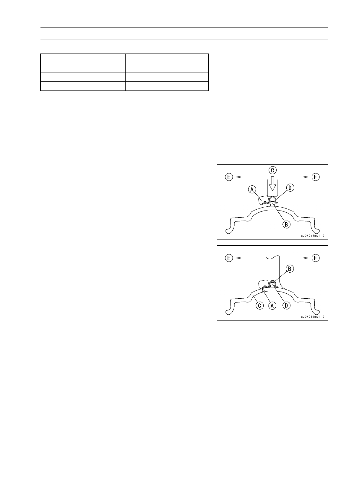
WHEELS/TIRES 10-13
Wheels (Rims)
Balance Weight
Part Number Weight
41075-0007
10 g (0.35 oz.)
41075-0008
20 g (0.71 oz.)
41075-0009
30 g (1.06 oz.)
NOTE
○
Balance weights are available from Kawasaki dealers
in 10, 20 and 30 grams (0.35, 0.71 and 1.06 oz.) sizes.
An imbalance of less than 10 grams (0.35 oz.) will not
usually affect running stability.
○
Do not use four or more balance weight (more than 90
gram, 3.2 oz.). If the wheel requires an excess balance
weight, disassemble the wheel to find the cause.
•
Slip the balance weight [A] onto the rib [B] by pushing or
lightly hammering [C] the clip [D].
Left Side [E]
Right Side [F]
•
Be sure to install the bala
nce weight.
○
Check that the blade [A] and clip [B] are fully seated on
the rim [C] and that the clip is hooked over the rib [D].
Left Side [E]
Right Side [F]
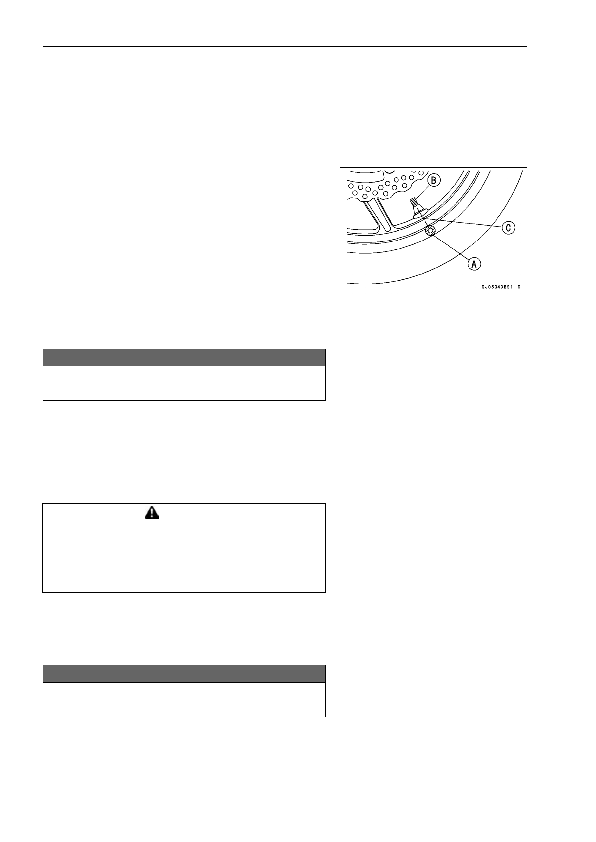
10-14 WHEELS/TIRES
Tires
Air Pressure Inspection/Adjustment
•
Refer to the Air Pressure Inspection in the Periodic Main-
tenance chapter.
Tire Inspection
•
Refer to the Wheel/Tire Damage Inspection in the Peri-
odic Maintenance chapter.
Tire Removal
•
Remove:
Wheels (see Front/Rear Wheel Removal)
Valve Core (Let out the air)
•
To maintain wheel balance, mark the valve stem position
on the tire with chalk so that the tire can be reinstalled in
the same position.
Chalk Mark or Yellow Mark [A]
Air Valve [B]
Align [C]
•
Lubricate the tire beads and rim flanges on both sides with
a soap and water solution or rubber lubricant. This helps
the tire beads slip off the rim flanges.
NOTICE
Never lubricate with engine oil or petroleum distil-
lates because they will deteriorate the tire.
•
Removethetirefromtherimusingasuitablecommer-
cially available tire changer.
NOTE
○
The tires cannot be removed with hand tools because
they fit the rims too tightly.
Tire Installation
WARNING
Some replacement tires may adversely affect han-
dling and cause an accident resulting in serious in-
jury or death. To ensure proper handling and sta-
bility, use only the recommended standard tires for
replacement, inflated to the standard pressure.
•
Inspect the rim and tire, and replace them if necessary.
•
Clean the sealing surfaces of the rim and tire, and smooth
thesealingsurfacesoftherimwithafineemeryclothif
necessary.
•
Remove the air valve and discard it.
NOTICE
Replace the air valve whenever the tire is replaced.
Do not reuse the air valve.
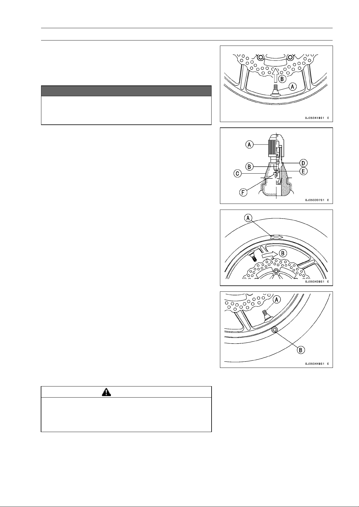
WHEELS/TIRES 10-15
Tires
•
Install a new valve in the rim.
○
Remove the valve cap, lubricate the stem seal [A] with a
soap and water solution or rubber lubricant, and pull [B]
the valve stem through the rim from the inside out until it
snaps into place.
NOTICE
Do not use engine oil or petroleum distillates to lu-
bricate the stem because they will deteriorate the
rubber.
○
The air valve is shown in the figure.
Valve Cap [A]
ValveCore[B]
Stem Seal [C]
Valve Stem [D]
Valve Seat [E]
Valve Opened [F]
•
Check the tire rotation mark on the front and rear tires and
install them on the rim accordingly.
Tire Rotation Mark [A]
Rotating Direction [B]
•
Position the tire on the rim so that the valve [A] align with
the tire balance mark [B] (the chalk mark made during
removal, or the yellow paint mark on a new tire).
•
Install the tire bead over the rim flange using a suitable
commercially available tire changer.
•
Lubricate the tire beads and rim flanges with a soap and
water solution or rubber lubricant to help seat the tire
beads in the sealing surfaces of the rim while inflating the
tire.
•
Center the rim in the tire beads, and inflate the tire with
compressed air until the tire beads seat in the sealing
surfaces.
WARNING
Overinflating a tire can cause it to explode, causing
serious injury or death. Be sure to install the valve
core whenever inflating the tire, and do not inflate
the tire to more than 400 kPa (4.0 kgf/cm², 57 psi).
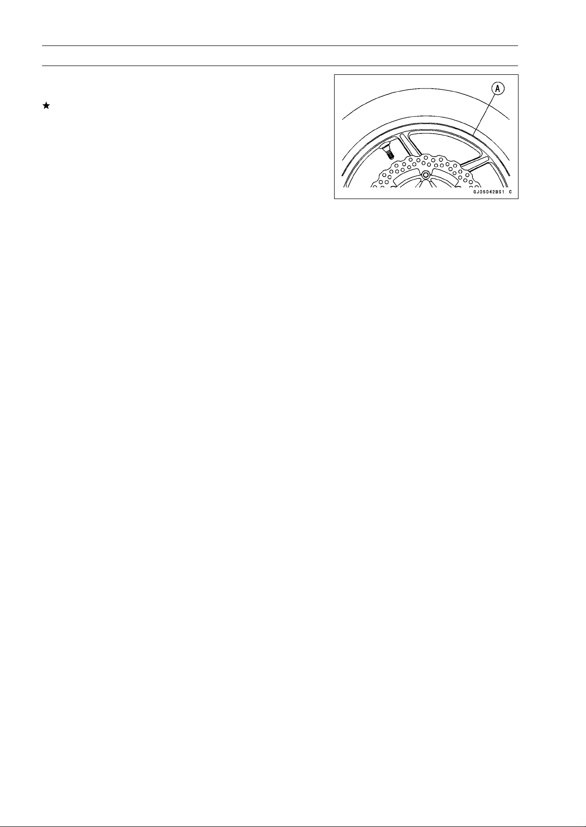
10-16 WHEELS/TIRES
Tires
•
Check to see that the rim lines [A] on both sides of the tire
sidewalls are parallel with the rim flanges.
If the rim flanges and tire sidewall rim lines are not parallel,
remove the valve core.
•
Lubricate the rim flanges and tire beads.
•
Install the valve core and inflate the tire again.
•
After the tire beads seat in the rim flanges, check for air
leakage.
○
Inflate the tire slightly above standard inflation.
○
Use a soap and water solution or submerge the tire, and
check for bubbles that would indicate leakage.
•
Adjust the air pressure to the specified pressure (see Air
Pressure Inspection in the Periodic Maintenance chap-
ter).
•
Install the air valve cap.
•
Adjust the wheel balance (see Balance Adjustment).
Tire Repair
Currently two types of repair for tubeless tires have come
into wide use. One type is called a temporary (external) re-
pair which can be carried out without removing the tire from
the rim, and the other type is called permanent (internal)
repair which requires tire removal. It is generally under-
stood that higher running durability is obtained by perma-
nent (internal) repairs than by temporary (external) ones.
Also, permanent (internal) repairs have the advantage of
permitting a thorough examination for secondary damage
not visible from external inspection of the tire. For these
reasons, Kawasaki does not recommend temporary (exter-
nal) repair. Only appropriate permanent (internal) repairs
are recommended. Repair methods may vary slightly from
make to make. Follow the repair methods indicated by the
manufacturer of the repair tools and materials so that safe
results can be obtained.
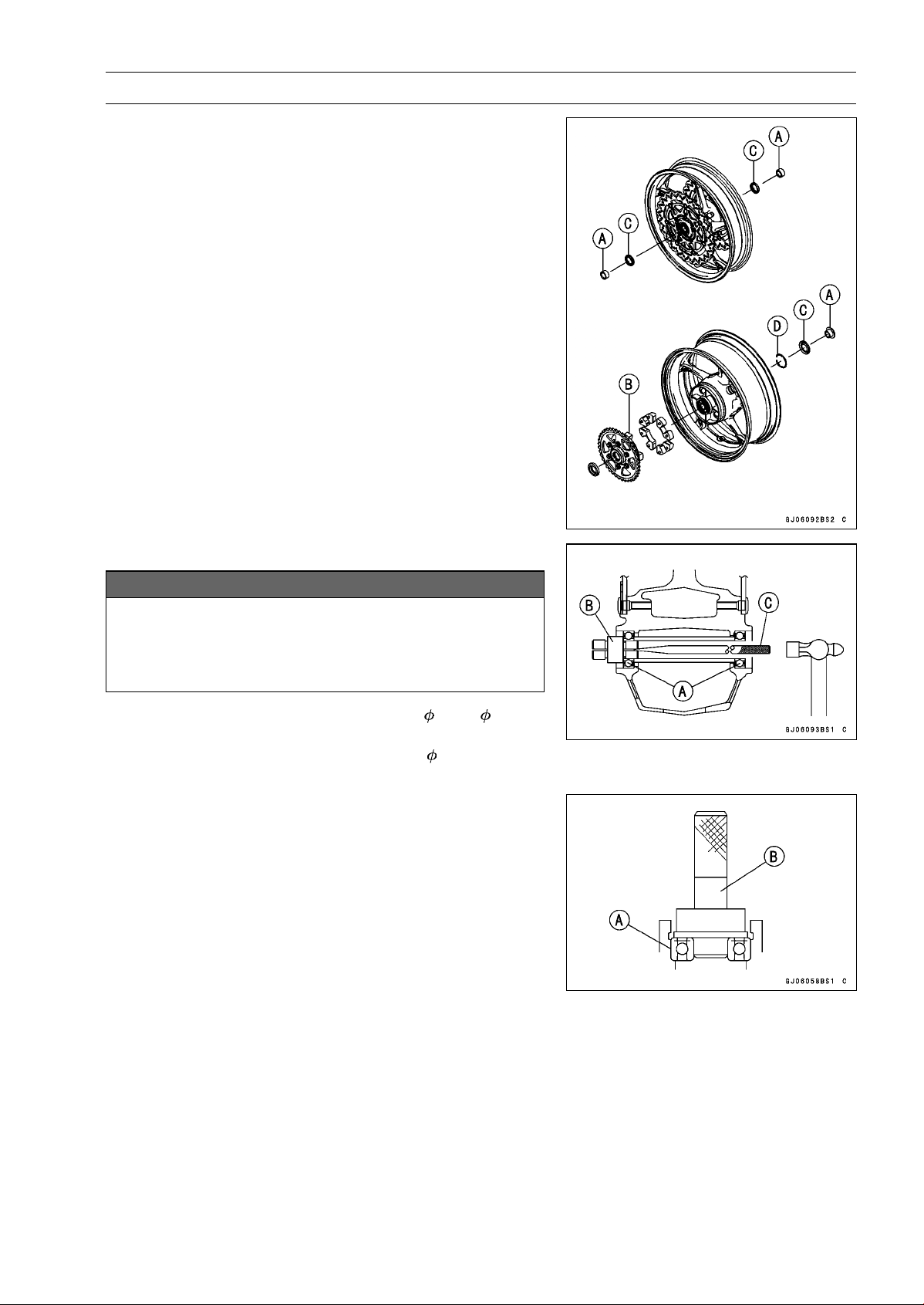
WHEELS/TIRES 10-17
Hub Bearing
Hub Bearing Removal
•
Remove the wheels (see Front/Rear Wheel Removal),
and take out the following.
Collars [A]
Coupling [B] (Out of rear hub)
Grease Seals [C]
Circlip [D]
Special Tool - Inside Circlip Pliers: 57001-143
•
Use the bearing remover to remove the hub bearings [A].
NOTICE
Do not lay the wheel on the ground with the disc
facing down. This can damage or warp the disc.
Place blocks under the wheel so that the disc does
not touch the ground.
Special Tools - Bearing Remover Head, 20 × 22 [B]:
57001-1293
Bearing Remover Shaft,
13 [C]: 57001
-1377
Hub Bearing Installation
•
Before installing the hub bearings, blow any dirt or foreign
particles out of the hub with compressed air to prevent
contamination of the bearings.
•
Replace the bearings with new ones.
•
Install the bearings by using the bearing driver set which
does not contact the bearing inner race.
NOTE
○
Install the bearings so that the marked side faces out.
•
Press in each right the bearing [A] until they are bottomed.
Special Tool - Bearing Driver Set [B]: 57001-1129
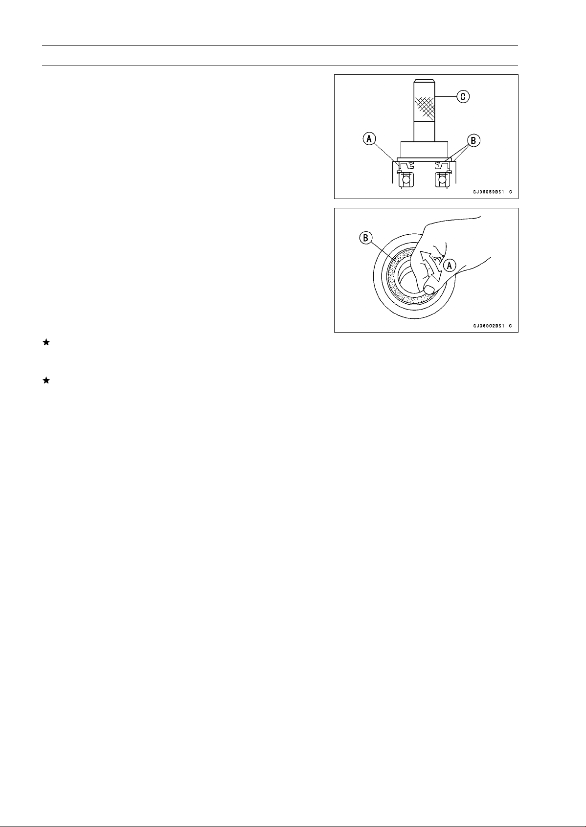
10-18 WHEELS/TIRES
Hub Bearing
•
Replace the circlip with a new one.
Special Tool - Inside Circlip Pliers: 57001-143
•
Replace the grease seals with new ones.
•
Press in the grease seals [A] so that the seal surface flush
[B] with the end of the hole.
○
Apply high-temperature grease to the grease seal lips.
Special Tool - Bearing Driver Set [C]: 57001-1129
Hub Bearing Inspection
Since the hub bearings are made to extremely close tol-
erances, the clearance can not normally be measured.
NOTE
○
Do not remove any bearings for inspection. If any bear-
ings are removed, they will need to be replaced with
new ones.
•
Turn each bearing in the hub back and forth [A] while
checking for plays, roughness, or binding.
If bearing play, roughness, or binding is found, replace
the bearing.
•
Examine the bearing seal [B] for tears or leakage.
If the seal is torn or is leaking, replace the bearing.
Hub Bearing Lubrication
NOTE
○
Since the hub bearings are packed with grease and
sealed, lubrication is not required.

FINAL DRIVE 11-1
11
Final Drive
Table of Contents
Exploded View........................................................................................................................ 11-2
Specifications ......................................................................................................................... 11-4
Special Tools .......................................................................................................................... 11-5
Drive Chain............................................................................................................................. 11-6
Drive Chain Slack Inspection ............................................................................................ 11-6
Drive Chain Slack Adjustment .......................................................................................... 11-6
Wheel Alignment Inspection/Adjustment .......................................................................... 11-6
Drive Chain Wear Inspection ............................................................................................ 11-6
Drive Chain Lubrication..................................................................................................... 11-6
Drive Chain Removal........................................................................................................ 11-6
Drive Chain Installation..................................................................................................... 11-7
Drive Chain Replacement................................................................................................. 11-7
Sprocket, Coupling ................................................................................................................. 11-11
Engine Sprocket Cover Removal...................................................................................... 11-11
Engine Sproket Cover Installation..................................................................................... 11-11
Engine Sprocket Removal ................................................................................................ 11-12
Engine Sprocket Installation ............................................................................................. 11-12
Rear Sprocket Removal.................................................................................................... 11-12
Rear Sprocket Installation................................................................................................. 11-13
Coupling Installation.......................................................................................................... 11-13
Coupling Bearing Removal ............................................................................................... 11-13
Coupling Bearing Installation ............................................................................................ 11-14
Coupling Bearing Inspection............................................................................................. 11-14
Coupling Bearing Lubrication............................................................................................ 11-14
Coupling Damper Inspection............................................................................................. 11-14
Sprocket Wear Inspection................................................................................................. 11-15
Rear Sprocket Warp Inspection ........................................................................................ 11-15
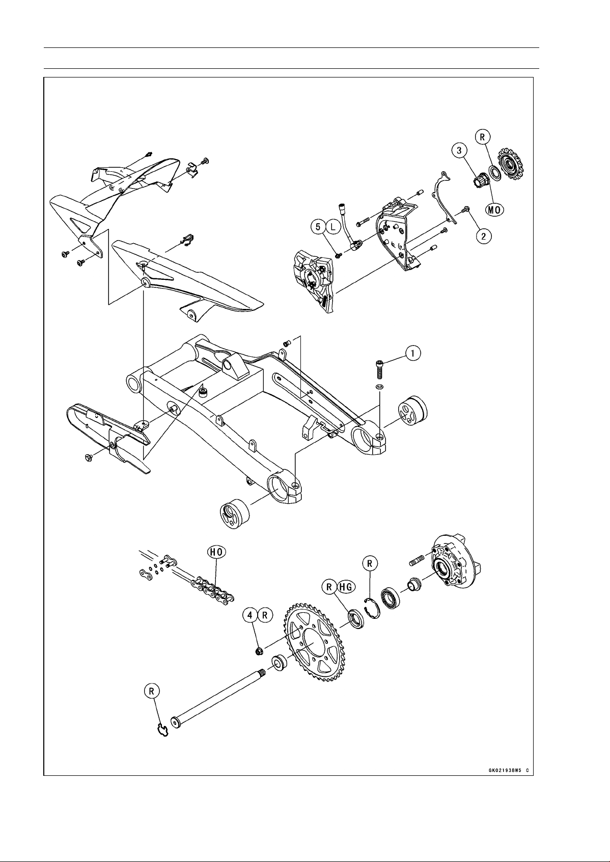
11-2 FINAL DRIVE
Exploded View

FINAL DRIVE 11-3
Exploded View
Torque
No. Fastener
N·m
kgf·m ft·lb
Remarks
1
Chain Adjuster Clamp Bolts
64 6.5 47
2 Drive Chain Guide Bolts 9.8 1.0 87 in·lb
3 Engine Sprocket Nut 125 12.7 92.2 MO
4 Rear Sprocket Nuts 59 6.0 44
5 Speed Sensor Mounting Bolt 6.9 0.70 61 in·lb L
HG: Apply high-temperature grease.
HO: Apply heavy oil.
MO: Apply molybdenum disulfide oil.
(mixture of the engine oil and molybdenum disulfide grease in a weight ratio 10 : 1)
R: Replacement Parts
11-4 FINAL DRIVE
Specifications
Item Standard Service Limit
Drive Chain
Drive Chain Slack 25 ∼ 30 mm (1.0 ∼ 1.2 in.) –––
Drive Chain Wear (20-link Length) 317.5 ∼ 318.2 mm (12.50 ∼ 12.53 in.) 319 mm (12.56 in.)
Standard Chain:
Make ENUMA –––
Type EK525ZX –––
Link 112 links –––
Link Pin Outside Diameter
(When drive chain replacing)
5.6 ∼ 6.0 mm (0.22 ∼ 0.24 in.)
–––
Link Plates Outside width
(When drive chain replacing)
20.35 ∼ 20.55 mm (0.8012 ∼ 0.8091 in.) –––
Sprockets
Rear Sprocket Warp 0.4 mm (0.016 in.) or less 0.5 mm (0.020 in.)
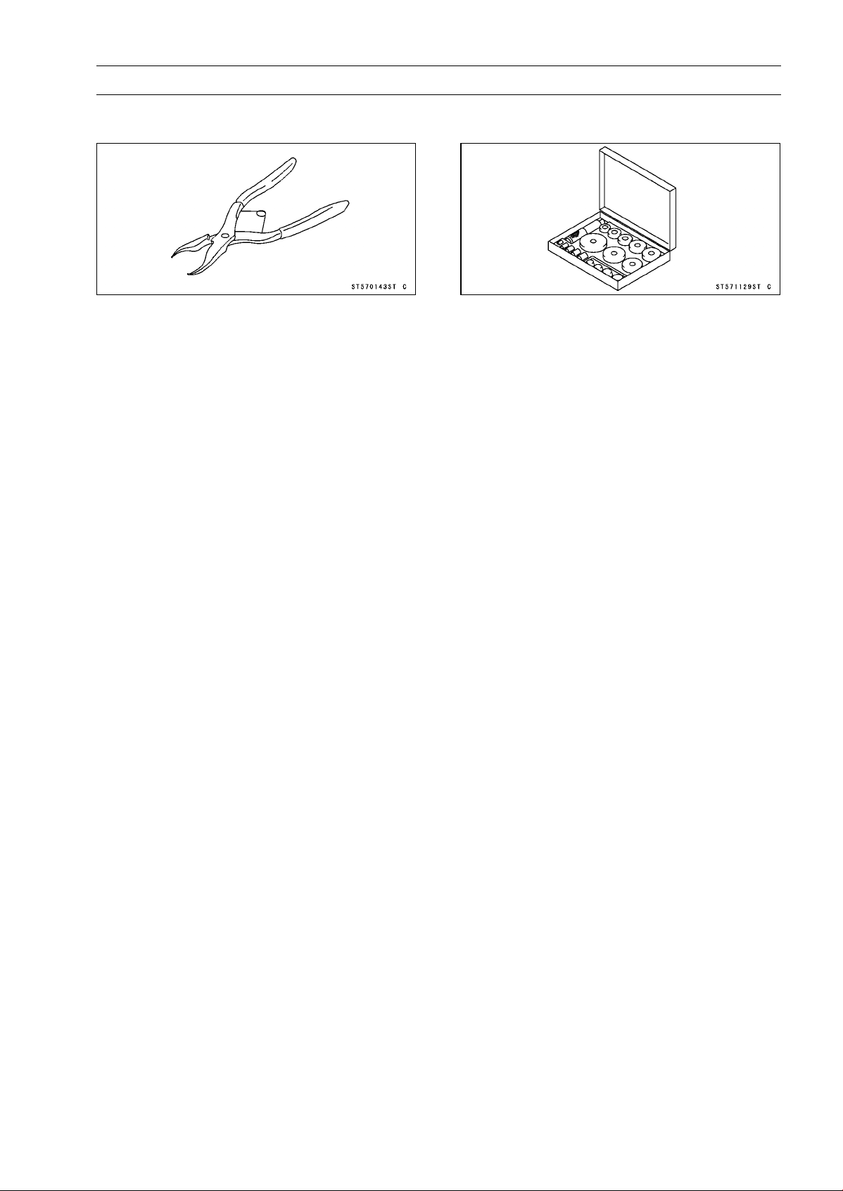
FINAL DRIVE 11-5
Special Tools
Inside Circlip Pliers:
57001-143
Bearing Driver Set:
57001-1129
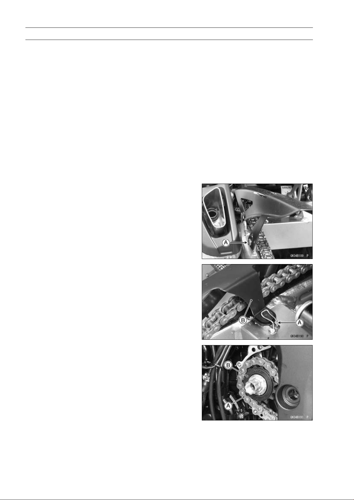
11-6 FINAL DRIVE
Drive Chain
Drive Chain Slack Inspection
•
Refer to the Drive Chain Slack Inspection in the Periodic
Maintenance chapter.
Drive Chain Slack Adjustment
•
Refer to the Drive Chain Slack Adjustment in the Periodic
Maintenance chapter.
Wheel Alignment Inspection/Adjustment
•
Refer to the Wheel Alignment Inspection in the Periodic
Maintenance chapter.
Drive Chain Wear Inspection
•
Refer to the Drive Chain Wear Inspection in the Periodic
Maintenance chapter.
Drive Chain Lubrication
•
Refer to the Drive Chain Lubrication Condition Inspection
in the Periodic Maintenance chapter.
Drive Chain Removal
•
Remove:
Mud Guard (see Mud Guard Removal in the Frame
chapter)
Rear Wheel (see Rear Wheel Removal in the
Wheels/Tires chapter)
Chain Cover Bolt [A]
•
Remove:
Clamp [A]
Chain Cover [B]
Swingarm (see Swingarm Removal in the Suspension
chapter)
•
Remove the drive chain [A] from the engine sprocket [B],
and take it off the chassis.
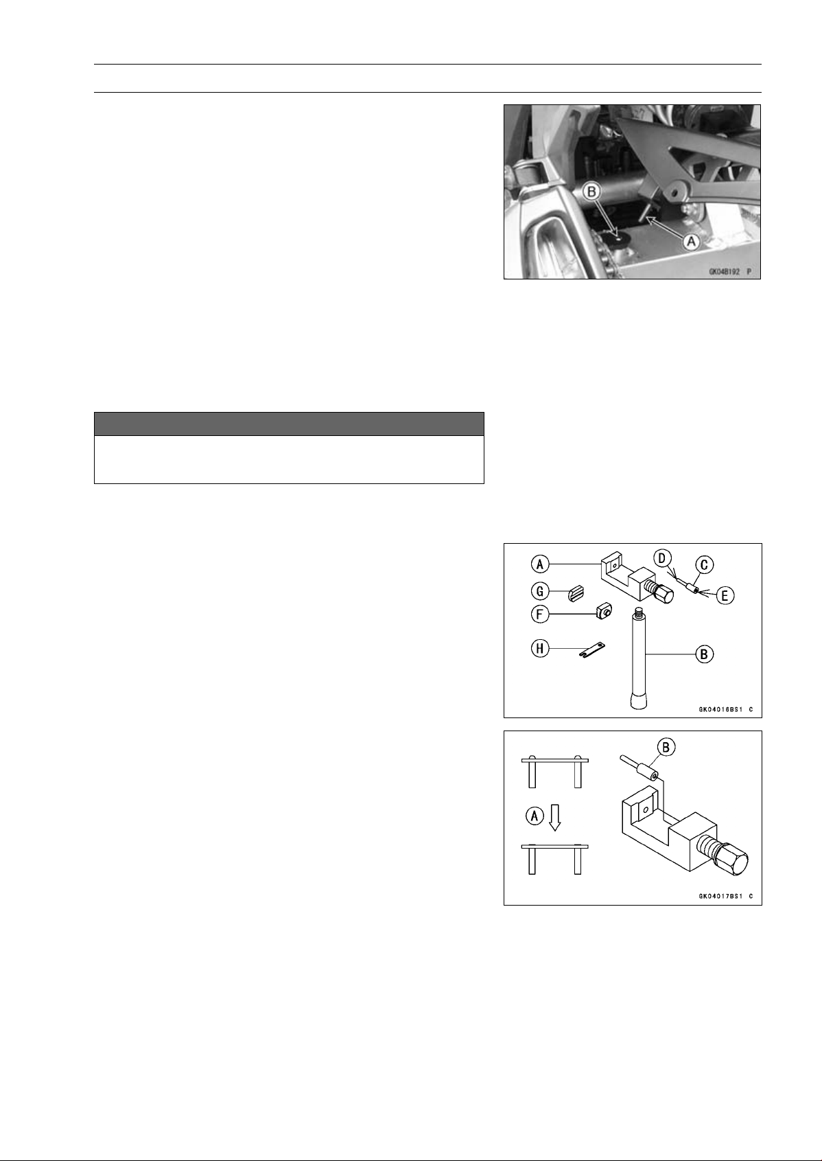
FINAL DRIVE 11-7
Drive Chain
Drive Chain Installation
•
Install the drive chain to the engine sprocket.
•
Install:
Swingarm (see Swingarm Installation in the Suspension
chapter)
Rear Wheel (see Rear Wheel Installation in the
Wheels/Tires chapter)
•
Insert the projection [A] on the chain cover into the
swingarm hole [B].
•
Adjust the drive chain slack after installing the chain (see
Drive Chain Slack Adjustment in the Periodic Mainte-
nance chapter).
Drive Chain Replacement
•
Remove:
Chain Cover (see Drive Chain Removal)
Engine Sprocket Cover (see Engine Sprocket Removal)
NOTICE
For safety, if the drive chain shall be replaced, re-
place it using a recommended tool.
Recommended Tool - Type: EK Joint Tool #50
Brand: ENUMA
Body [A]
Handlebar [B]
Cutting and Riveting Pin [C]
For Cutting [D]
For Riveting [E]
Plate Holder (A) [F]
Plate Holder (B) [G]
Gauge [H]
•
Grind [A] the pin head to make it flat.
•
Set the cutting and riveting pin [B] as shown in the figure.
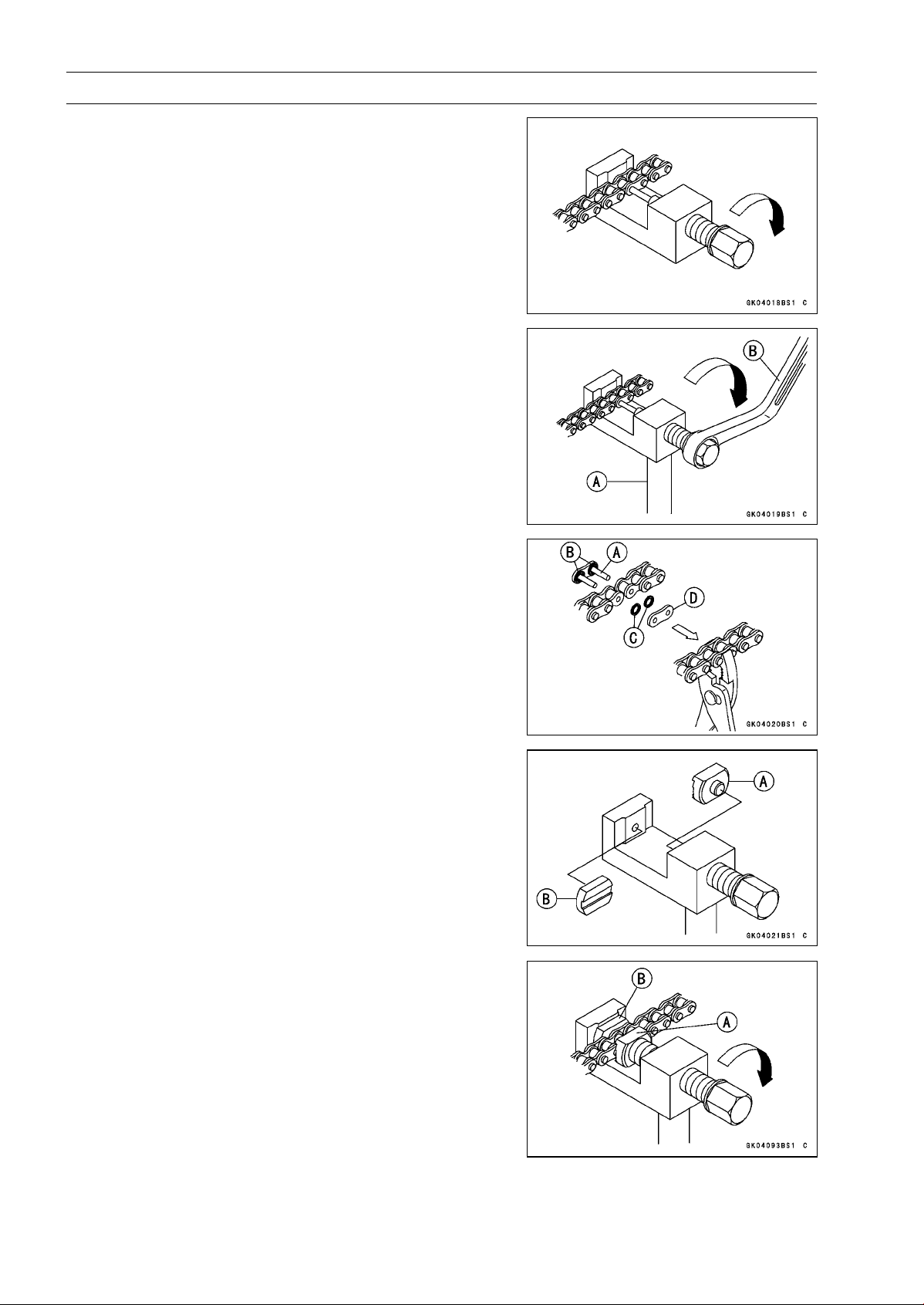
11-8 FINAL DRIVE
Drive Chain
•
Screw the pin holder until it touches chain pin.
•
Be sure that the cutting pin hits center of chain pin.
•
Screw the handlebar [A] into body.
•
Turn the pin holder with wrench [B] clockwise to extract
chain pin.
•
Replace the link pin, link plate and grease seals.
•
Apply grease to the link pins [A] and grease seals [B] [C].
•
Engage the drive chain on the engine and rear sprockets.
•
Insert the link pins in the drive chain ends.
•
Install the grease seals.
•
Install the link plate [D] so that the mark faces out.
•
Push the link plate by hand or plier to fix it.
•
In case of grease seals chain, be sure to set the grease
seals correctly.
•
Set the plate holder (A) [A] and plate holder (B) [B] on the
body.
•
Fit the plate holder (A) [A] to link plate.
•
Turn the pin holder by hand until plate holder (B) [B]
touches the other link plate.
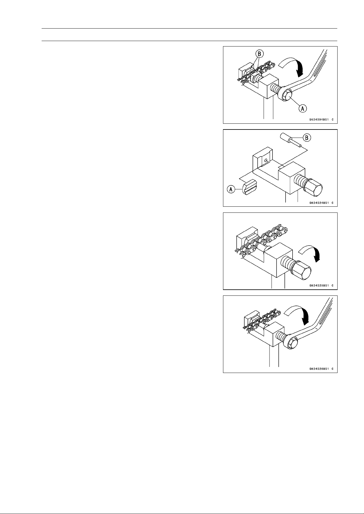
FINAL DRIVE 11-9
Drive Chain
•
Turn the pin holder [A] by wrench clockwise until two pins
of link come into groove of plate holders [B].
•
Take off the plate holder.
•
Set the plate holder (B) [A] and cutting and riveting pin [B]
as shown in the figure.
•
Turn the pin holder until riveting pin touches link pin.
•
Turnthewrenchclockwiseuntiltipofrivetingpinhitsto
the link pin.
•
Rivet it.
•
Same work for the other link pin.
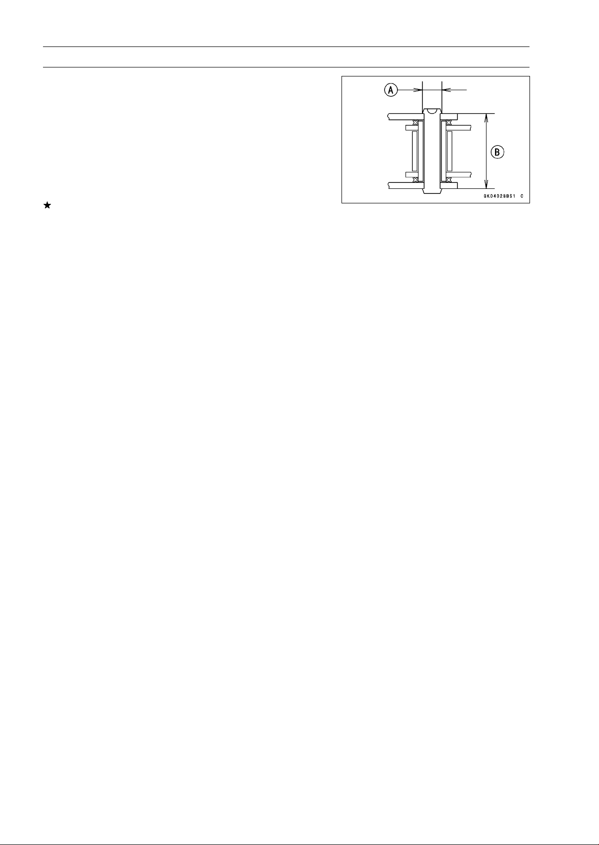
11-10 FINAL DRIVE
Drive Chain
•
After staking, check the staked area of the link pin for
cracks.
•
Measure the outside diameter [A] of the link pin and link
plates width [B].
Link Pin Outside Diameter
Standard: 5.6
∼ 6.0 mm (0.22 ∼ 0.24 in.)
Link Plates Outside Width
Standard: 20.35
∼ 20.55 mm (0.8012 ∼ 0.8091 in.)
If the reading exceeds the specified length, cut and rejoin
the chain again.
•
Check:
Movement of the Rollers
•
Adjust the drive chain slack after installing the chain (see
Drive Chain Slack Adjustment in the Periodic Mainte-
nance chapter).
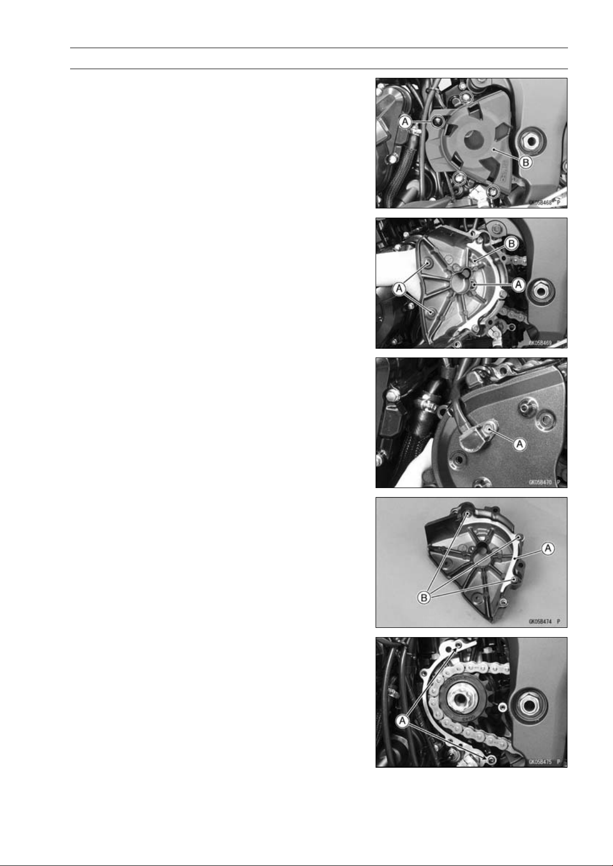
FINAL DRIVE 11-11
Sprocket, Coupling
Engine Sprocket Cover Removal
•
Remove:
Engine Sprocket Inner Cover Bolts [A]
Engine Sprocket Inner and Outer Cover [B]
•
Remove the engine sprocket outer cover screws [A] to
sparate the outer and inner cover [B].
•
Remove the speed sensor bolt [A].
Engine Sproket Cover Installation
•
Be sure to install the drive chain guide [A].
•
Tighten:
Torque - Drive Chain Guide Bolts [B]: 9.8 N·m (1.0 kgf·m, 87
in·lb)
•
Apply a non-parmanent locking agent to the thread of the
speed senor mounting bolt.
•
Tighten:
Torque - Speed Sensor Mounting Bolt: 6.9 N·m (0.70 kgf·m,
61 in·lb)
•
Install the engine sprocket outer cover to the inner cover.
•
Be sure to install the dowel pins [A].
•
Install the engine sprocket inner cover.
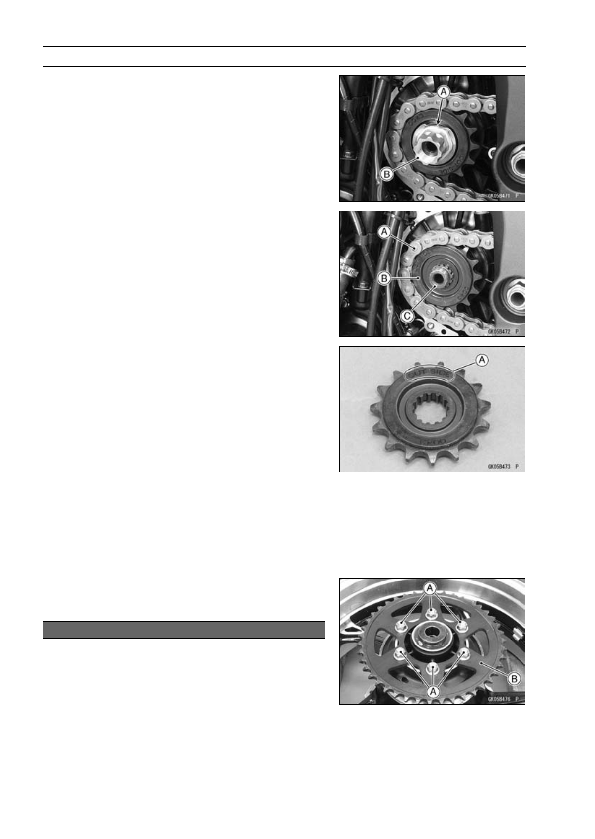
11-12 FINAL DRIVE
Sprocket, Coupling
Engine Sprocket Removal
•
Remove the engine sprocket cover (see Engine Sprocket
Cover Removal).
•
Flatten out the bended washer [A].
•
Remove the engine sprocket nut [B] and washer.
NOTE
○
When loosening the engine sprocket nut, hold the rear
brake on.
•
Raise the rear wheel off the ground with the stand.
•
Loosen the drive chain (see Drive Chain Slack Adjust-
ment in the Periodic Maintenance chapter).
•
Remove the drive chain from the rear sprocket toward the
right.
•
Disengage the drive chain [A] from the engine sprocket
[B].
•
Pull the engine sprocket off the output shaft [C].
Engine Sprocket Installation
•
Replace the sprocket washer.
•
Install the engine sprocket so that “OUT SIDE” letters [A]
face outward.
•
Apply molybdenum disulfide oil solution to the threads
and the seating surface of the engine sprocket nut.
•
Tighten:
Torque - Engine Sprocket Nut: 125 N·m (12.7 kgf·m, 92.2
ft·lb)
NOTE
○
Tighten the nut while applying the rear brake.
•
After torquing the engine sprocket nut, bend the one side
of the washer over the nut.
•
Adjust the drive chain slack after installing the engine
sprocket (see Drive Chain Slack Adjustment in the Pe-
riodic Maintenance chapter).
Rear Sprocket Removal
•
Remove the rear wheel (see Rear Wheel Removal in the
Wheels/Tires chapter).
NOTICE
Do not lay the wheel on the ground with the disc
facing down. This can damage or warp the disc.
Place blocks under the wheel so that the disc does
not touch the ground.
•
Remove the rear sprocket nuts [A].
•
Remove the rear sprocket [B].
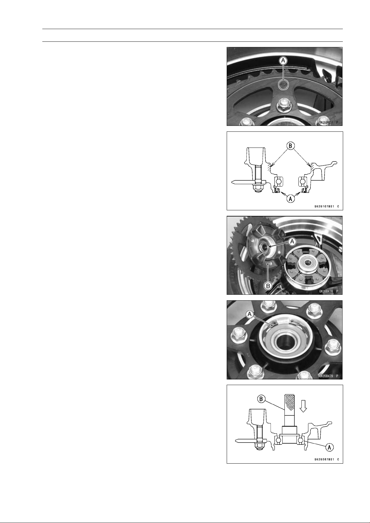
FINAL DRIVE 11-13
Sprocket, Coupling
Rear Sprocket Installation
•
Install the sprocket facing the tooth number marking [A]
outward.
•
Replace the rear sprocket nuts with new ones.
•
Tighten:
Torque - Rear Sprocket Nuts: 59 N·m (6.0 kgf·m, 44 ft·lb)
•
Install the rear wheel (see Rear Wheel Installation in the
Wheels/Tires chapter).
Coupling Installation
•
Apply high-temperature grease to the following parts.
Coupling Grease Seal Lip [A]
Coupling Internal Surface [B]
•
Install:
Collar [A]
Coupling [B]
Coupling Bearing Removal
•
Remove:
Coupling
Grease Seal
Circlip [A]
Special Tool - Inside Circlip Pliers: 57001-143
•
Remove the bearing [A] by tapping from the wheel side.
Special Tool - Bearing Driver Set [B]: 57001-1129
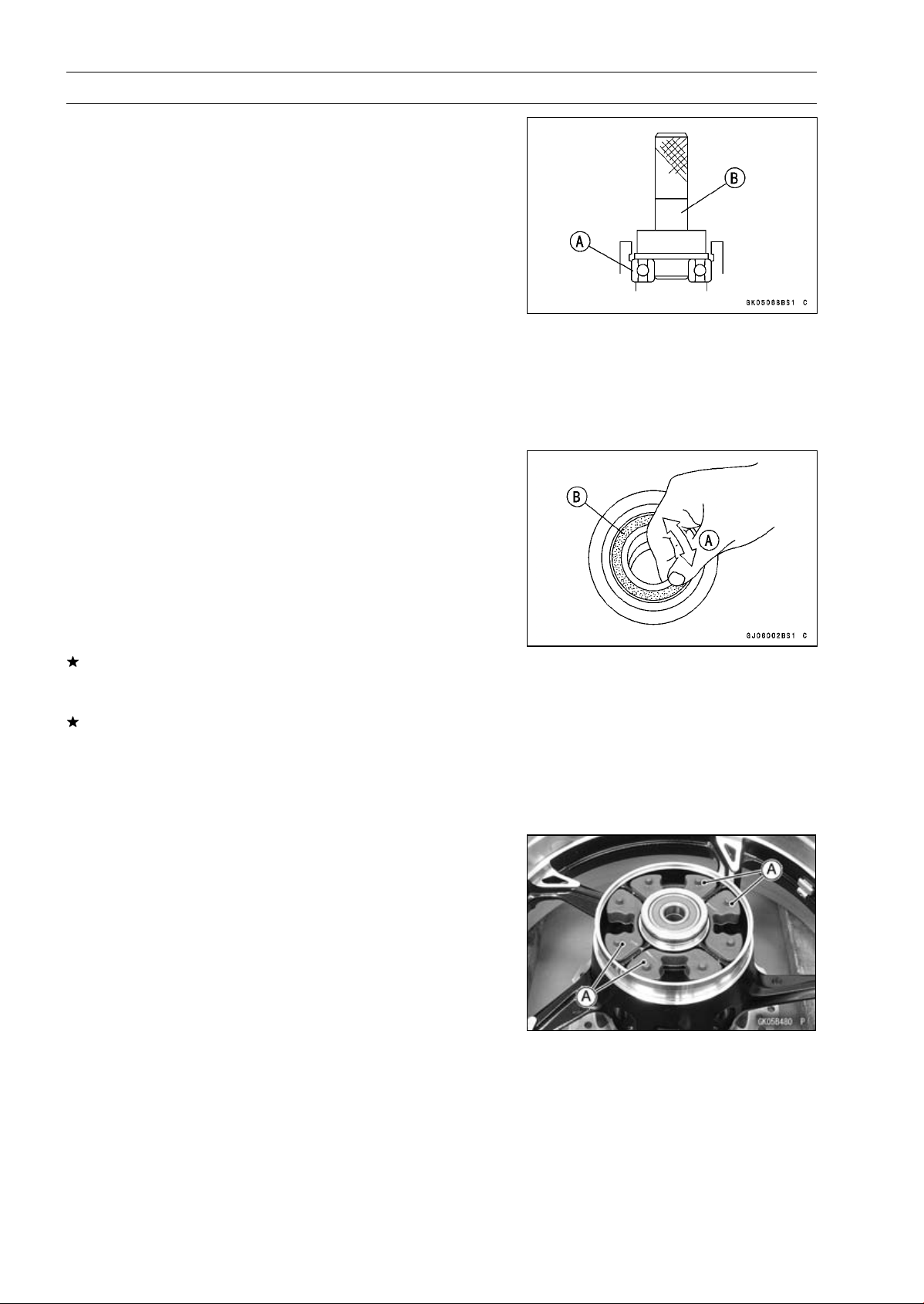
11-14 FINAL DRIVE
Sprocket, Coupling
Coupling Bearing Installation
•
Replace the bearing with a new one.
•
Press in the bearing [A] until it is bottomed.
Special Tool - Bearing Driver Set [B]: 57001-1129
•
Pack the bearing with high-temperature grease.
•
Replace the circlip with a new one.
Special Tool - Inside Circlip Pliers: 57001-143
•
Replace the grease seal with a new one.
•
Press in the grease seal so that the seal surface is flush
with the end of the hole.
○
Apply high-temperature grease to the grease seal lip.
Special Tool - Bearing Driver Set: 57001-1129
Coupling Bearing Inspection
Since the coupling bearing is made to extremely close
tolerances, the clearance can not normally be measured.
NOTE
○
It is not necessary to remove the coupling bearing for
inspection. If the bearing is removed, it will need to be
replaced with a new one.
•
Turn the bearing in the coupling back and forth [A] while
checking for plays, roughness or binding.
If the bearing play, roughness or binding is found, replace
the bearing.
•
Examine the bearing seal [B] for tears or leakage.
If the seal is torn ot is leaking, replace the bearing.
Coupling Bearing Lubrication
•
Pack the bearing with good quality bearing grease. Turn
the bearing around by hand a few times to make sure the
grease is distributed uniformly inside the bearing.
Coupling Damper Inspection
•
Remove the rear wheel coupling, and inspect the rubber
dampers [A].
•
Replace the damper if it appears damaged or deterio-
rated.
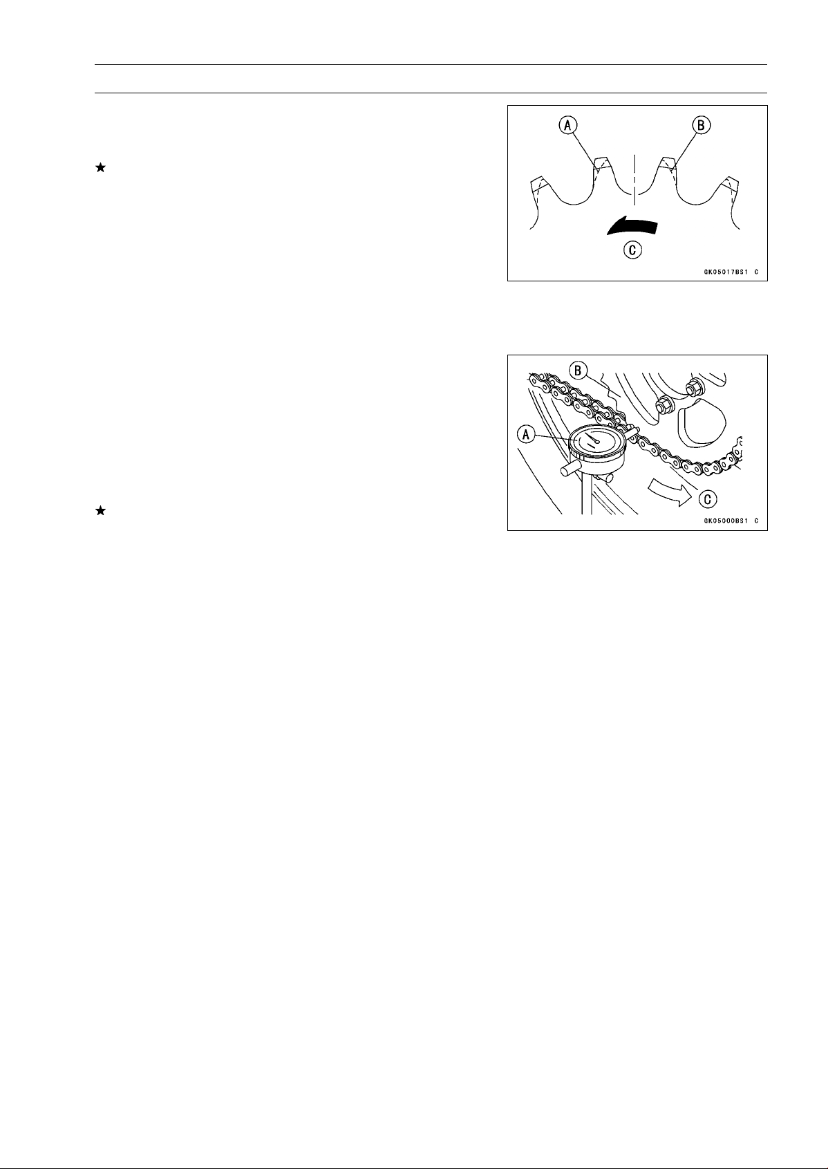
FINAL DRIVE 11-15
Sprocket, Coupling
Sprocket Wear Inspection
•
Visually inspect the engine and rear sprocket teeth for
wear and damage.
If the teeth are worn as illustrated, replace the sprocket,
and inspect the drive chain wear (see Drive Chain Wear
Inspection in the Periodic Maintenance chapter).
Worn Tooth (Engine Sprocket) [A]
Worn Tooth (Rear Sprocket) [B]
Direction of Rotation [C]
NOTE
○
If a sprocket requires replacement, the chain is proba-
bly worn also. When replacing a sprocket, inspect the
chain.
Rear Sprocket Warp Inspection
•
Raise the rear wheel off the ground with the stand so that
it will turn freely.
•
Set a dial gauge [A] against the rear sprocket [B] near the
teeth as shown in the figure, and rotate [C] the rear wheel
to measure the sprocket runout (warp). The difference
between the highest and lowest dial gauge readings is
the amount of runout (warp).
If the runout exceeds the service limit, replace the rear
sprocket.
Rear Sprocket Warp
Standard: 0.4 mm (0.016 in.) or less
Service Limit: 0.5 mm (0.020 in.)


BRAKES 12-1
12
Brakes
Table of Contents
Exploded View........................................................................................................................ 12-3
Specifications ......................................................................................................................... 12-10
Special Tools .......................................................................................................................... 12-11
Brake Lever, Brake Pedal....................................................................................................... 12-12
Brake Lever Position Adjustment...................................................................................... 12-12
Brake Pedal Position Inspection ....................................................................................... 12-12
Brake Pedal Position Adjustment...................................................................................... 12-12
Brake Pedal Removal ....................................................................................................... 12-12
Brake Pedal Installation .................................................................................................... 12-13
Calipers .................................................................................................................................. 12-14
Front Caliper Removal...................................................................................................... 12-14
Rear Caliper Removal....................................................................................................... 12-14
Caliper Installation ............................................................................................................ 12-15
Front Caliper Disassembly................................................................................................ 12-15
Front Caliper Assembly..................................................................................................... 12-15
Rear Caliper Disassembly ................................................................................................ 12-15
Rear Caliper Assembly ..................................................................................................... 12-15
Caliper Fluid Seal Damage Inspection.............................................................................. 12-16
Rear Caliper Dust Boot and Friction Boot Damage Inspection......................................... 12-16
Caliper Piston and Cylinder Damage Inspection .............................................................. 12-16
Rear Caliper Holder Shaft Wear Inspection...................................................................... 12-17
Brake Pads............................................................................................................................. 12-18
Front Brake Pad Removal................................................................................................. 12-18
Front Brake Pad Installation.............................................................................................. 12-18
Rear Brake Pad Removal ................................................................................................ 12-19
Rear Brake Pad Installation .............................................................................................. 12-19
Brake Pad Wear Inspection .............................................................................................. 12-19
Master Cylinder ...................................................................................................................... 12-20
Front Master Cylinder Removal ........................................................................................ 12-20
Front Master Cylinder Installation ..................................................................................... 12-20
Rear Master Cylinder Removal......................................................................................... 12-20
Rear Master Cylinder Installation...................................................................................... 12-21
Front Master Cylinder Disassembly .................................................................................. 12-21
Rear Master Cylinder Disassembly................................................................................... 12-21
Master Cylinder Assembly ................................................................................................ 12-21
Master Cylinder Inspection (Visual Inspection)................................................................. 12-22
Brake Disc .............................................................................................................................. 12-23
Brake Disc Removal ......................................................................................................... 12-23
Brake Disc Installation ...................................................................................................... 12-23
Brake Disc Wear Inspection.............................................................................................. 12-23
Brake Disc Warp Inspection.............................................................................................. 12-23
Brake Fluid ............................................................................................................................. 12-24
Brake Fluid Level Inspection............................................................................................. 12-24
Brake Fluid Change .......................................................................................................... 12-24
Brake Line Bleeding.......................................................................................................... 12-24
Brake Hose............................................................................................................................. 12-28
Brake Hose Removal/Installation...................................................................................... 12-28
Brake Hose and Pipe Inspection....................................................................................... 12-28
Anti-Lock Brake System (Equipped Models) .......................................................................... 12-29
Parts Location................................................................................................................... 12-29

12-2 BRAKES
ABS Servicing Precautions............................................................................................... 12-33
ABS Troubleshooting Outline............................................................................................ 12-35
Inquiries to Rider............................................................................................................... 12-38
Self-diagnosis Outline....................................................................................................... 12-40
Self-diagnosis Procedures................................................................................................ 12-40
Service Code Clearing Procedures................................................................................... 12-41
How to Read Service Codes............................................................................................. 12-44
How to Erase Service Codes............................................................................................ 12-44
ABS Indicator Light (LED) Inspection ............................................................................... 12-46
Solenoid Coil Temperature Abnormal [High-Temperature] (Service Code 11).................. 12-46
Solenoid Valve Inspection (Service Code 13, 14, 17, 18)................................................. 12-46
ABS Solenoid Valve Relay Inspection (Service Code 19) ................................................ 12-47
Front, Rear Wheel Rotation Difference Abnormal (Service Code 25) .............................. 12-47
ABS Motor Relay Inspection (Service Code 35)............................................................... 12-48
Front Wheel Rotation Sensor Signal Abnormal (Service Code 42) .................................. 12-48
Front Wheel Rotation Sensor Wiring Inspection (Service Code 43) ................................ 12-49
Rear Wheel Rotation Sensor Signal Abnormal (Service Code 44)................................... 12-50
Rear Wheel Rotation Sensor Wiring Inspection (Service Code 45).................................. 12-50
Power Supply Voltage Abnormal (Low-Voltage) (Service Code 52) ................................. 12-51
Power Supply Voltage Abnormal (Over-Voltage) (Service Code 53) ................................ 12-51
ECU Inspection (Service Code 55)................................................................................... 12-52
Wheel Rotation Sensor Signal Abnormal [Too High Speed] (Service Code 93) .............. 12-52
ABS Hydraulic Unit Removal ............................................................................................ 12-52
ABS Hydraulic Unit Installation ......................................................................................... 12-54
ABS Hydraulic Unit Inspection.......................................................................................... 12-54
Front Wheel Rotation Sensor Removal ............................................................................ 12-55
Front Wheel Rotation Sensor Installation ......................................................................... 12-55
Rear Wheel Rotation Sensor Removal ............................................................................. 12-56
Rear Wheel Rotation Sensor Installation.......................................................................... 12-56
Wheel Rotation Sensor Inspection.................................................................................... 12-57
Wheel Rotation Sensor Air Gap Inspection ...................................................................... 12-57
Wheel Rotation Sensor Rotor Inspection.......................................................................... 12-58
ABS Solenoid Valve Relay Fuse (20 A) Removal............................................................. 12-58
ABS Motor Relay Fuse (30 A) Removal ........................................................................... 12-58
ABS ECU Fuse (10 A) Removal ....................................................................................... 12-58
Fuse Installation................................................................................................................ 12-59
Fuse Inspection................................................................................................................. 12-59

BRAKES 12-3
Exploded View
This page intentionally left blank.
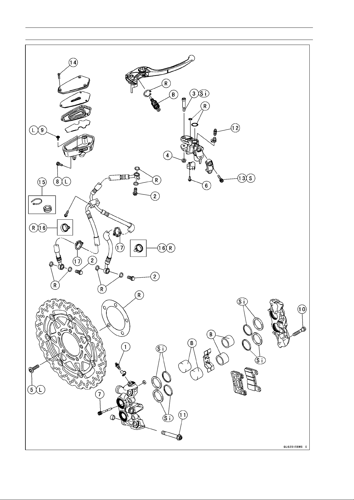
12-4 BRAKES
Exploded View
BRAKES 12-5
Exploded View
Torque
No. Fastener
N·m
kgf·m ft·lb
Remarks
1 Bleed Valves 7.8 0.80 69 in·lb
2 Brake Hose Banjo Bolts 25 2.5 18
3 Brake Lever Pivot Bolt 1.0 0.10 8.8 in·lb Si
4 Brake Lever Pivot Bolt Locknut 5.9 0.60 52 in·lb
5 Front Brake Disc Mounting Bolts 27 2.8 20 L
6
Front Brake Light Switch Screw
1.2 0.12 11 in·lb
7 Front Brake Pad Pins 15 1.5 11
8 Front Brake Reservoir Bolt 7.8 0.80 69 in·lb L
9 Front Brake Reservoir Screw 1.2 0.12 11 in·lb L
10 Front Caliper Assembly Bolts 22 2.2 16
11 Front Caliper Mounting Bolts 34 3.5 25
12
Front Master Cylinder Bleed Valve
7.8 0.80 69 in·lb
13
Front Master Cylinder Clamp Bolts
11 1.1 97 in·lb
S
14 Front Master Cylinder Reservoir Cap Screws 1.5 0.15 13 in·lb
15. ZR1000DA/EA
16. ∼ ZR1000DB/EB (Refer to Front Fender Installation in the Frame chapter.)
17. Face the lock portion of the clamp backward.
B: Apply brake fluid.
L: Apply a non-permanent locking agent.
R: Replacement Parts
S: Follow the specified tightening sequence.
Si: Apply silicone grease (ex. PBC grease).
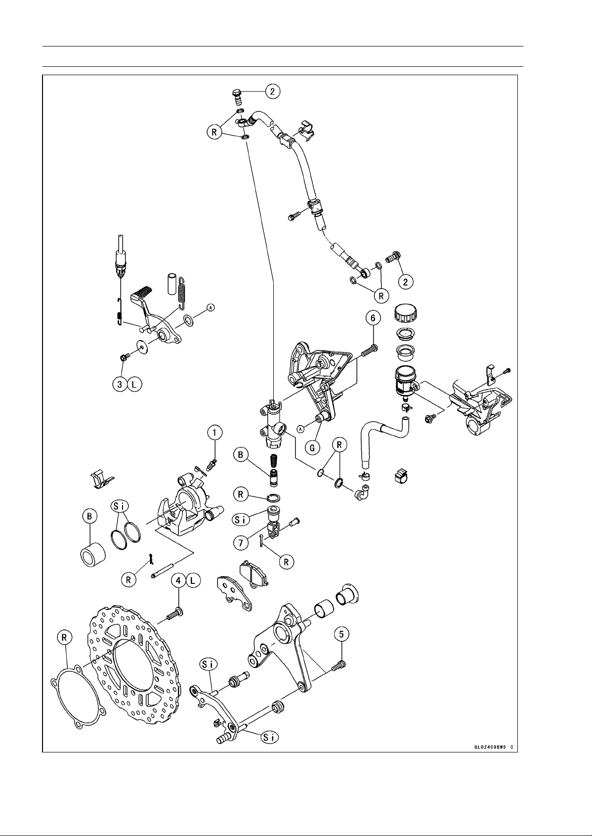
12-6 BRAKES
Exploded View

BRAKES 12-7
Exploded View
Torque
No. Fastener
N·m
kgf·m ft·lb
Remarks
1 Bleed Valve 7.8 0.8 69 in·lb
2 Brake Hose Banjo Bolts 25 2.5 18
3 Brake Pedal Bolt 8.8 0.90 78 in·lb L
4 Rear Brake Disc Mounting Bolts 27 2.8 20 L
5 Rear Caliper Mounting Bolts 25 2.5 18
6
Rear Master Cylinder Mounting Bolts
25 2.5 18
7
Rear Master Cylinder Push Rod Locknut
17 1.7 12
B: Apply brake fluid.
G: Apply grease.
L: Apply a non-permanent locking agent.
R: Replacement Parts
Si: Apply silicone grease (ex. PBC grease).
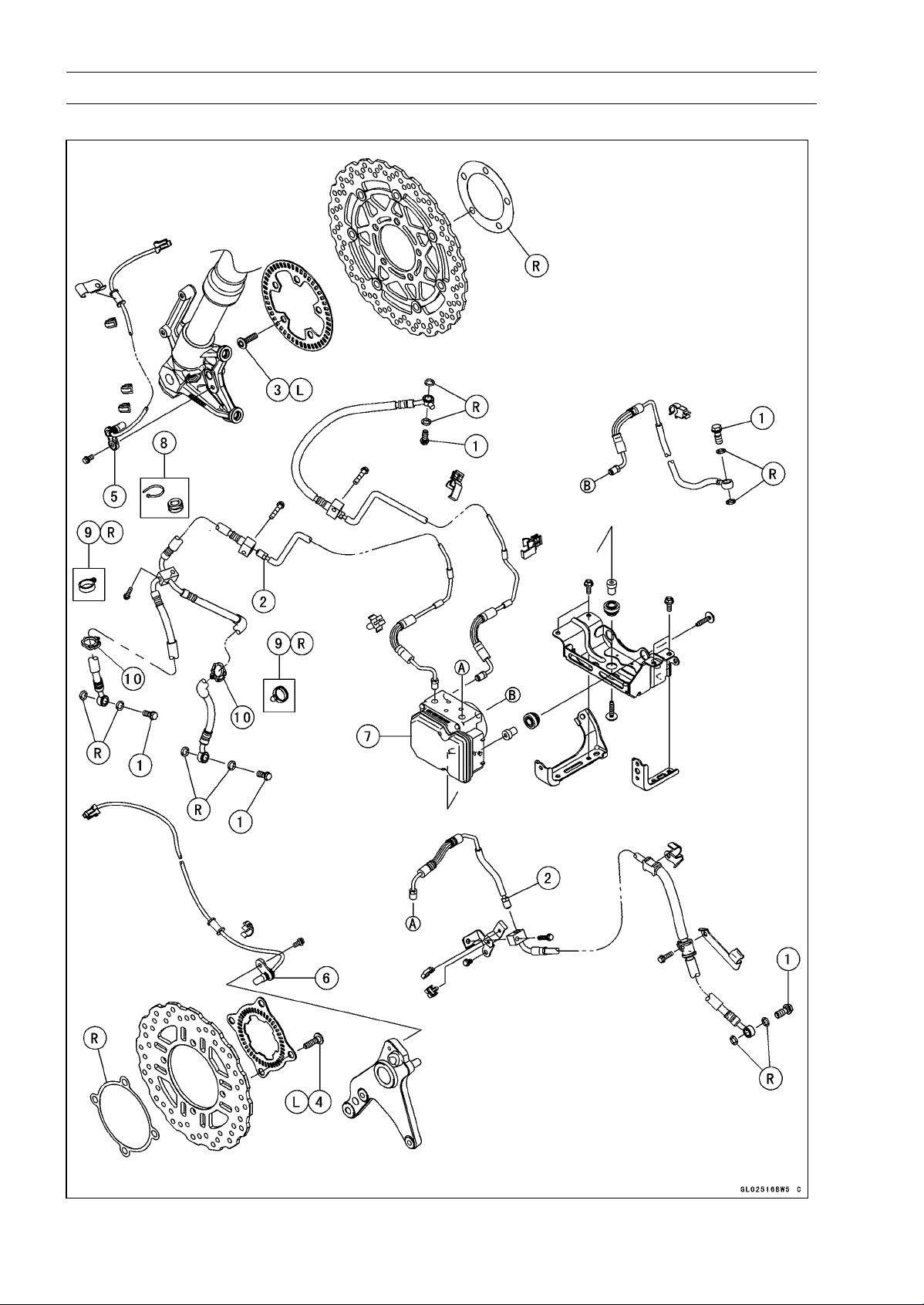
12-8 BRAKES
Exploded View
ABS Equipped Models

BRAKES 12-9
Exploded View
Torque
No. Fastener
N·m
kgf·m ft·lb
Remarks
1 Brake Hose Banjo Bolts 25 2.5 18
2 Brake Pipe Joint Nuts 18 1.8 13
3 Front Brake Disc Mounting Bolts 27 2.8 20 L
4 Rear Brake Disc Mounting Bolts 27 2.8 20 L
5. Front Wheel Rotation Sensor
6. Rear Wheel Rotation Sensor
7. ABS Hydraulic Unit
8. ZR1000EA
9. ∼ ZR1000EB (Refer to Front Fender Installation in the Frame chapter.)
10. Face the lock portion of the clamp backward.
L: Apply a non-permanent locking agent.
R: Replacement Parts
NOTE
○
When disassembling the brake hose and pipe, disassemble them by the unit as shown in the
exploded view.
○
The components of ZR1000EA are same as ZR1000EB
∼
.

12-10 BRAKES
Specifications
Item Standard Service Limit
Brake Lever, Brake Pedal
Brake Lever Position 6-way adjustable (to suit rider) –––
Brake Lever Free Play Non-adjustable –––
Pedal Free Play Non-adjustable –––
Pedal Position
About 62 mm (2.4 in.) bel
ow footpeg top
–––
Brake Pads
Lining Thickness:
Front 4.0 mm (0.16 in.) 1 mm (0.04 in.)
Rear 5.0 mm (0.20 in.) 1 mm (0.04 in.)
Brake Discs
Thickness:
Front 5.3 ∼ 5.7 mm (0.21 ∼ 0.22 in.) 5.0 mm (0.20 in.)
Rear 5.8 ∼ 6.2 mm (0.23 ∼ 0.24 in.) 5.5 mm (0.22 in.)
Runout TIR 0.15 mm (0.006 in.) or less TIR 0.3 mm (0.01 in.)
Brake Fluid
Grade DOT4 –––
ABS (Equipped Models)
Wheel Rotation Sensor
Air Gap:
Front
1.98 ∼ 2.86 mm (0.078
0 ∼ 0.113 in.)
–––
Rear 1.12 ∼ 1.85 mm (0.0441 ∼ 0.0728 in.) –––
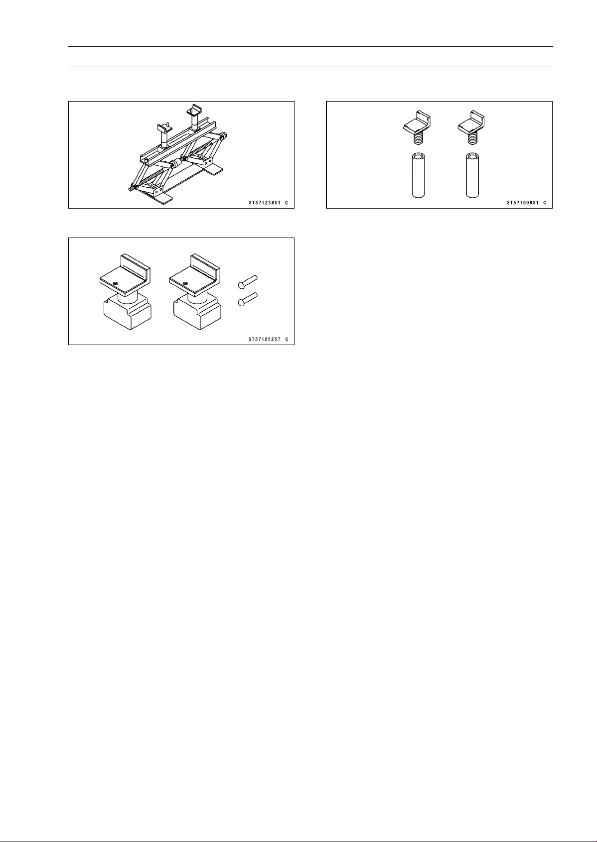
BRAKES 12-11
Special Tools
Jack:
57001-1238
Attachment Jack:
57001-1252
Jack Attachment:
57001-1608
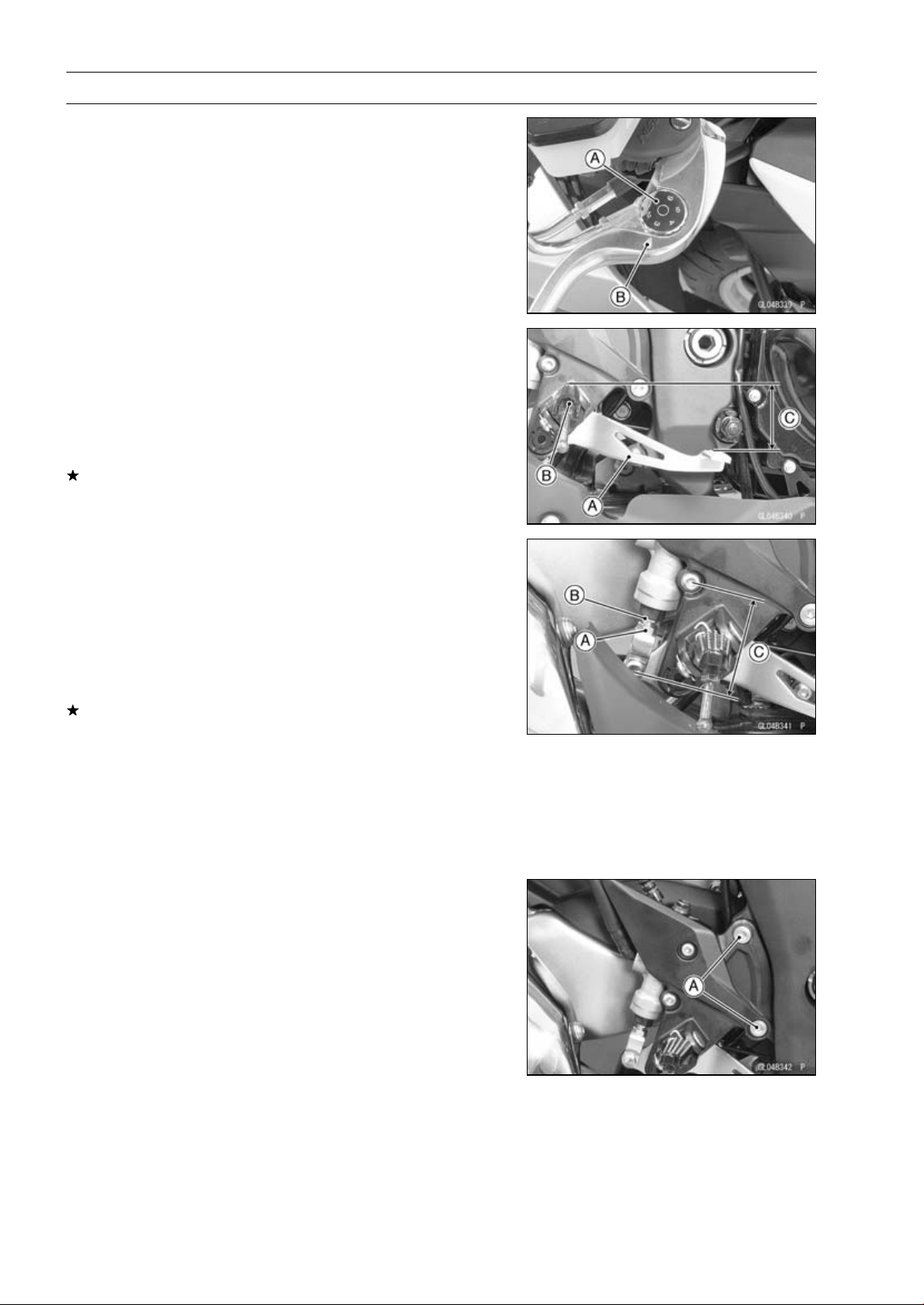
12-12 BRAKES
Brake Lever, Brake Pedal
Brake Lever Position Adjustment
The brake lever adjuster has 6 positions so that the brake
lever position can be adjusted to suit the operator’s hand.
•
Push the lever forward and turn the adjuster [A] to align
the number with the arrow mark [B] on the lever holder.
○
The distance from the grip to the lever is minimum at num-
ber 6 and maximum at number 1.
Brake Pedal Position Inspection
•
Check that the brake pedal [A] is in the correct position.
[B] Footpeg
Pedal Position
Standard: About 62 mm (2.4 in.) [C] below top of
footpeg
If it is incorrect, adjust the brake pedal position.
Brake Pedal Position Adjustment
NOTE
○
Usually it is not necessary to adjust the pedal position,
but always adjust it when the push rod locknut has been
loosened.
•
Loosen the locknut [A] and turn the push rod with the hex
head [B] to achieve the correct pedal position.
If the length [C] shown is 70 ±1 mm (2.76 ±0.04 in.),the
pedal position will be within the standard range.
•
Tighten:
Torque - Rear Master Cylinder Push Rod Locknut: 17 N·m
(1.7 kgf·m, 12 ft·lb)
•
Check the brake light switch operation (see Brake Light
Switch Operation Inspection in the Periodic Maintenance
chapter).
Brake Pedal Removal
•
Remove:
Rear Lower Fairing (see Rear Lower Fairing Removal in
the Frame chapter)
Right Front Footpeg Bracket Bolts [A]
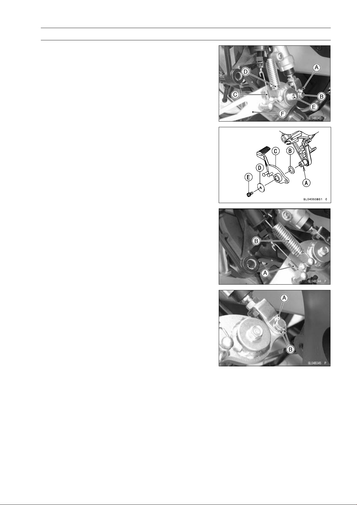
BRAKES 12-13
Brake Lever, Brake Pedal
•
Remove:
Cotter Pin [A]
Joint Pin [B]
Rear Brake Light Switch Spring [C]
Return Spring [D]
Brake Pedal Bolt [E]
Brake Pedal [F]
Brake Pedal Installation
•
Apply grease to the footpeg pivot shaft [A].
•
Install:
Washer [B]
Brake Pedal [C]
Washer [D]
•
Apply a non-permanent locking agent to the threads of
the brake pedal bolt [E], and tighten it.
Torque - Brake Pedal Bolt: 8.8 N·m (0.90 kgf·m, 78 in·lb)
•
Hook the longer end of the rear brake light switch spring
[A] on the brake light switch.
•
Hook the upper end of the return spring [B] on the footpeg
bracket hook.
○
Face the both lower spring ends forward.
•
Replace the cotter pin [A] with a new one.
•
Insert the cotter pin and bend the pin ends [B].
•
Install the front footpeg bracket.
•
Tighten:
Torque - Front Footpeg Bracket Bolts: 25 N·m (2.5 kgf·m,
18 ft·lb)
•
Check the brake pedal position (see Brake Pedal Position
Inspection).
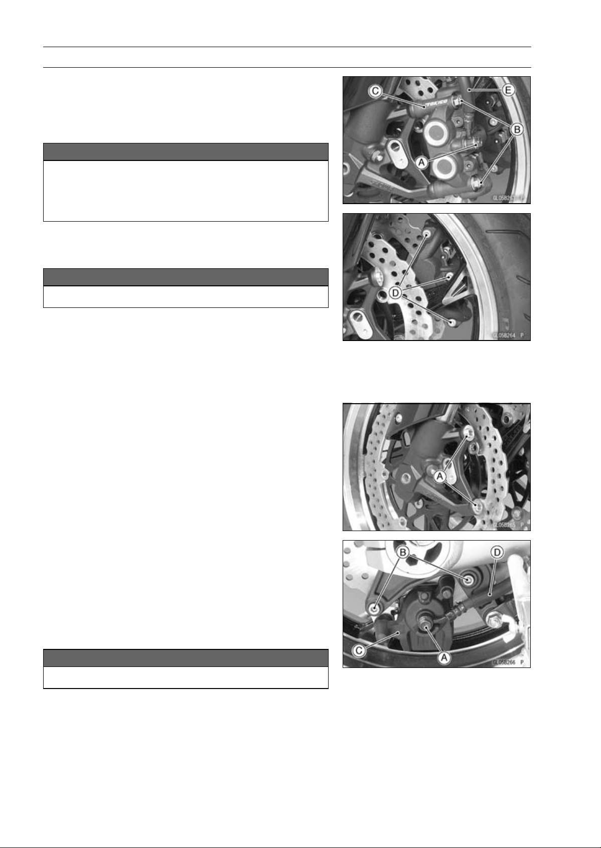
12-14 BRAKES
Calipers
Front Caliper Removal
•
Loosen the banjo bolt [A] at the brake hose lower end,
and tighten it loosely.
•
Unscrew the caliper mounting bolts [B], and detach the
caliper [C] from the disc.
NOTICE
Do not loosen the caliper assembly bolts [D]. Take
out only the caliper mounting bolts for caliper re-
moval. Loosening the caliper assembly bolts will
cause brake fluid leakage.
•
Unscrew the banjo bolt and remove the brake hose [E]
from the caliper (see Brake Hose and Pipe Replacement
in the Periodic Maintenance chapter).
NOTICE
Immediately wash away any brake fluid that spills.
NOTE
○
If the caliper is to be disassembled after removal and if
compressed air is not available, disassemble the caliper
before the brake hose is removed (see Caliper Rubber
Parts Replacement in the Periodic Maintenance chap-
ter).
•
Remove the collars [A] from the fork leg.
Rear Caliper Removal
•
Loosen the banjo bolt [A] at the brake hose lower end,
and tighten it loosely.
•
Unscrew the caliper mounting bolts [B], and detach the
caliper [C] from the disc.
•
Unscrew the banjo bolt and remove the brake hose [D]
from the caliper (see Brake Hose and Pipe Replacement
in the Periodic Maintenance chapter).
NOTICE
Immediately wash away any brake fluid that spills.
NOTE
○
If the caliper is to be disassembled after removal and if
compressed air is not available, disassemble the caliper
before the brake hose is removed (see Caliper Rubber
Parts Replacement in the Periodic Maintenance chap-
ter).
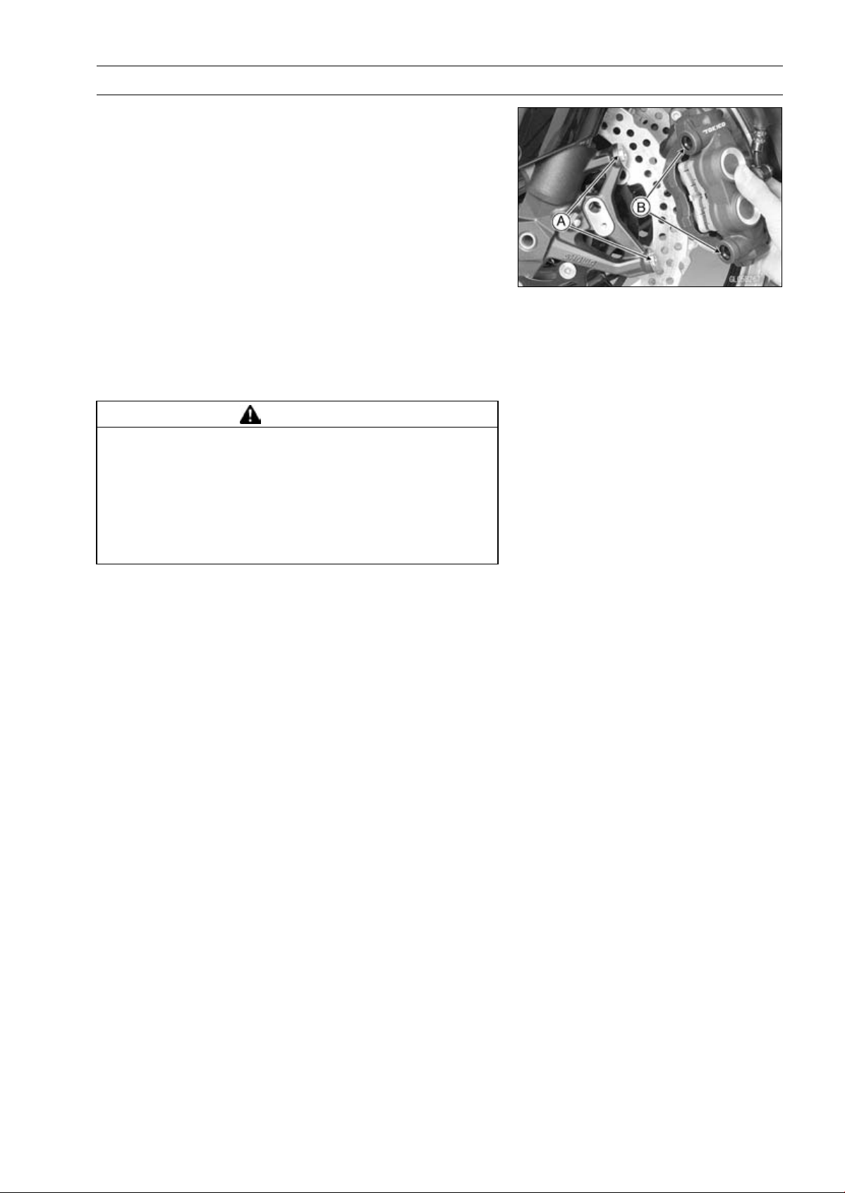
BRAKES 12-15
Calipers
Caliper Installation
•
Install the caliper and brake hose lower end.
○
For the front caliper, install the collars [A] on the fork leg
and fit the holes [B] of the front caliper to the collars.
○
Replace the washers on each side of hose fitting with new
ones.
•
Tighten:
Torque - Caliper Mounting Bolts
Front: 34 N·m (3.5 kgf·m, 25 ft·lb)
Rear: 25 N·m (2.5 kgf·m, 18 ft·lb)
Brake Hose Banjo Bolts: 25 N·m (2.5 kgf·m, 18
ft·lb)
•
Bleed the brake line (see Brake Line Bleeding).
•
Check the brake for good braking power, no brake drag,
and no fluid leakage.
WARNING
After servicing, it takes several applications of the
brake lever or pedal before the brake pads contact
the disc, which could result in increased stopping
distance and cause an accident resulting in injury
or death. Do not attempt to ride the motorcycle until
a firm brake lever or pedal is obtained by pumping
the lever or pedal until the pads are against the disc.
Front Caliper Disassembly
•
Refer to the Caliper Rubber Parts Replacement in the Pe-
riodic Maintenance chapter.
Front Caliper Assembly
•
Refer to the Caliper Rubber Parts Replacement in the Pe-
riodic Maintenance chapter.
Rear Caliper Disassembly
•
Refer to the Caliper Rubber Parts Replacement in the Pe-
riodic Maintenance chapter.
Rear Caliper Assembly
•
Refer to the Caliper Rubber Parts Replacement in the Pe-
riodic Maintenance chapter.
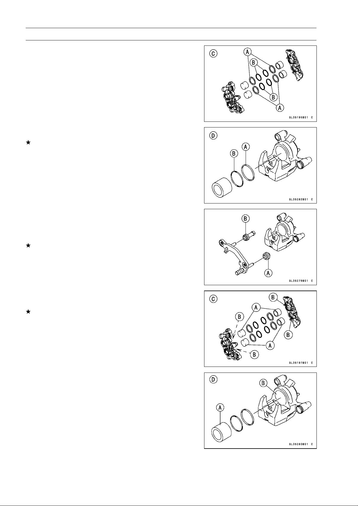
12-16 BRAKES
Calipers
Caliper Fluid Seal Damage Inspection
The fluid seal (piston seal) [A] is placed around the pis-
ton to maintain clearance between the pad and the disc. If
the seal is in a poor condition, it could lead the pad to wear
excessively or the brake to drag, which may cause the tem-
perature of the discs or the brake fluid to increase.
•
Replace the fluid seal if it exhibits any of the conditions
listed below.
○
Brake fluid leakage around the pad.
○
Brakes overheat.
○
Considerable difference in inner and outer pad wear.
○
Seal and piston are stuck together.
If the fluid seal is replaced, replace the dust seal [B] as
well. Also, replace all seals every other time the pads are
changed.
Front Caliper [C]
Rear Caliper [D]
Rear Caliper Dust Boot and Friction Boot Damage
Inspection
•
Check that the dust boot [A] and friction boot [B] are not
cracked, worn, swollen, or otherwise damaged.
If they show any damage, replace it.
Caliper Piston and Cylinder Damage Inspection
•
Visually inspect the pistons [A] and cylinder surfaces [B].
Replace the caliper if the cylinder and piston are badly
scores or rusty.
Front Caliper [C]
Rear Caliper [D]
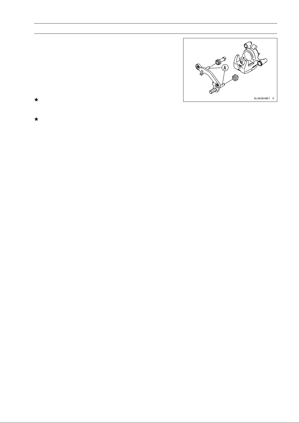
BRAKES 12-17
Calipers
Rear Caliper Holder Shaft Wear Inspection
The caliper body must slide smoothly on the caliper holder
shafts [A]. If the body does not slide smoothly, one pad will
wear more than the other, pad wear will increase, and con-
stant drag on the disc will raise brake and brake fluid tem-
perature.
•
Check to see that the caliper holder shafts are not badly
worn or stepped, and that the rubber friction boots are not
damaged.
If the rubber friction boot is damaged, replace the rubber
friction boot. To replace the friction boot, remove the pads
and the caliper bracket.
If the caliper holder shaft is damage, replace the caliper
bracket.
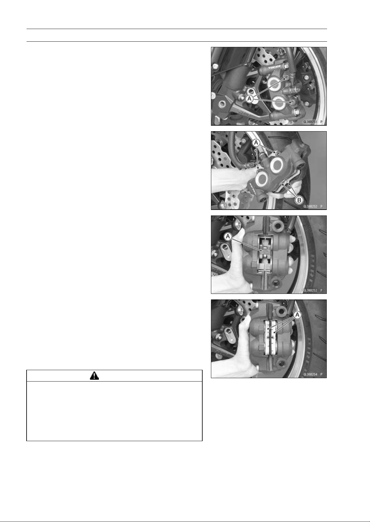
12-18 BRAKES
Brake Pads
Front Brake Pad Removal
•
Loosen the pad pins [A].
•
Remove the front caliper with the hose installed (see Front
Caliper Removal).
•
Remove:
Pad Pins [A]
Brake Pads [B]
Front Brake Pad Installation
•
Check that the pad spring [A] is in place on the caliper.
•
Push the caliper pistons in by hand as far as they will go.
•
Install the brake pads [A] on the pad spring correctly.
○
Fit the pad into the groove of the caliper as shown in the
figure.
•
Install the pad pins while pushing the brake pads lightly.
•
Tighten the pad pins temporarily.
•
Install the front caliper (see Caliper Installation).
•
Tighten:
Torque - Front Brake Pad Pins: 15 N·m (1.5 kgf·m, 11 ft·lb)
WARNING
After servicing, it takes several applications of the
brake lever before the brake pads contact the disc,
which could result in increased stopping distance
and cause an accident resulting in injury or death.
Do not attempt to ride the motorcycle until a firm
brake lever is obtained by pumping the lever until
the pads are against the disc.
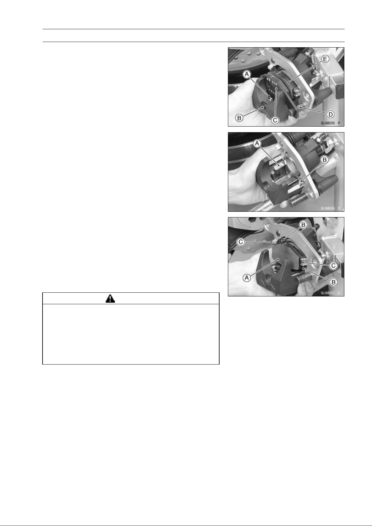
BRAKES 12-19
Brake Pads
Rear Brake Pad Removal
•
Remove the rear caliper with the hose installed (see Rear
Caliper Removal).
•
Remove:
Clip [A]
Pad Pin [B]
•
Remove the brake pad [C] of the jaw side from the holder
shaft [D], then remove the other pad [E].
Rear Brake Pad Installation
•
Check that the pad spring [A] and guide [B] are in place
on the caliper and holder.
•
Push the caliper piston in by hand as far as it will go.
•
Install the brake pad [A] on the piston side first, then install
the other pad on the holder shaft.
○
Fit the projections [B] of the piston side pad into the re-
cesses [C] of the caliper holder.
•
Install the pad pin while pushing the brake pad of the jaw
side lightly.
•
Install a new clip.
○
The clip must be “outside” of the pad.
•
Install the rear caliper (see Rear Caliper Installation).
WARNING
After servicing, it takes several applications of the
brake pedal before the brake pads contact the disc,
which could result in increased stopping distance
and cause an accident resulting in injury or death.
Do not attempt to ride the motorcycle until a firm
brake pedal is obtained by pumping the pedal until
the pads are against the disc.
Brake Pad Wear Inspection
•
Refer to the Brake Pad Wear Inspection in the Periodic
Maintenance chapter.
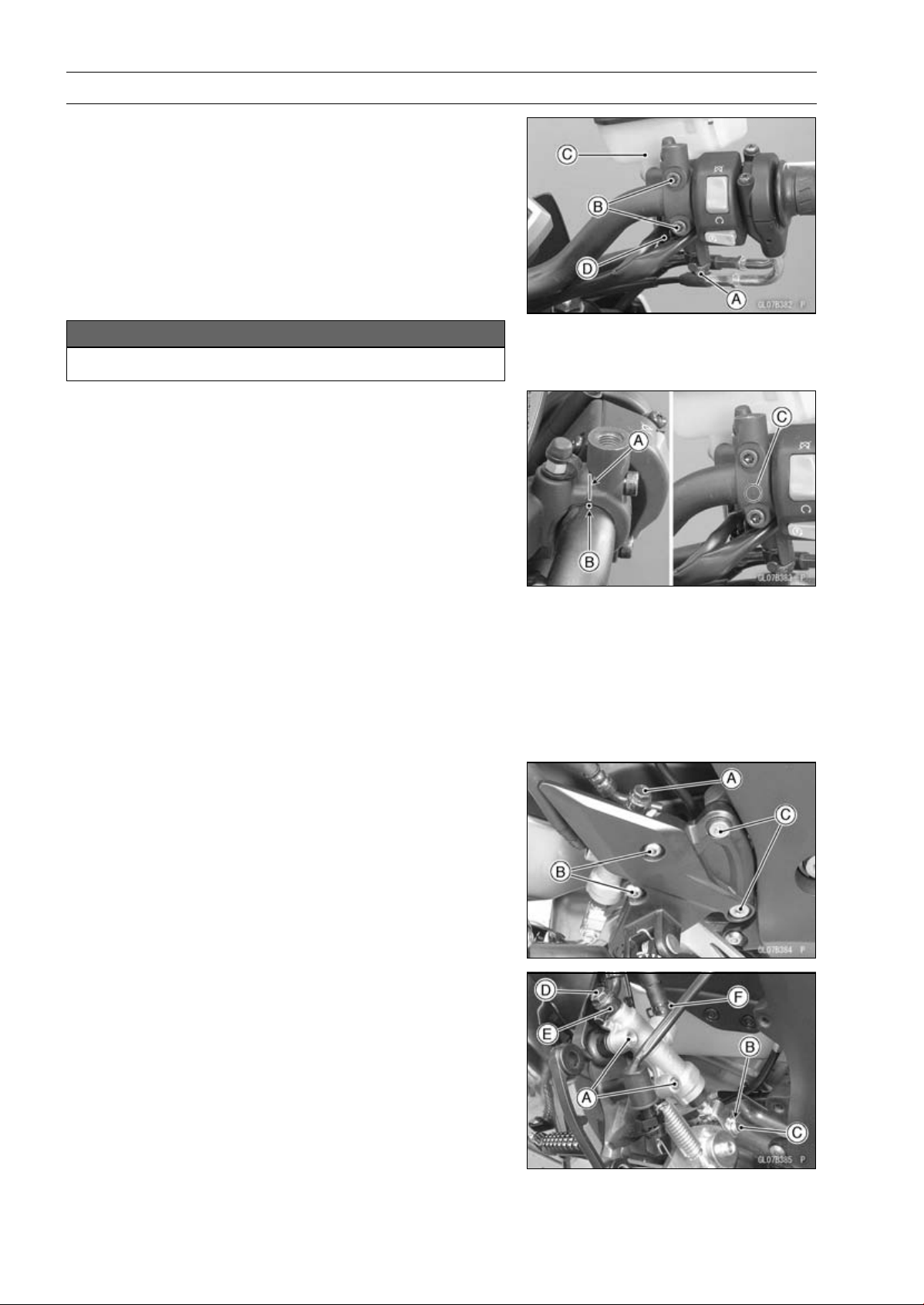
12-20 BRAKES
Master Cylinder
Front Master Cylinder Removal
•
Remove the rear view mirror (see Rear View Mirror Re-
moval in the Frame chapter).
•
Remove the banjo bolt [A] to disconnect the brake hose
from the master cylinder (see Brake Hose Removal/In-
stallation).
•
Unscrew the clamp bolts [B], and take off the master cylin-
der [C] as an assembly with the reservoir, brake lever, and
brake switch installed.
•
Disconnect the front brake light switch connector [D].
NOTICE
Immediately wash away any brake fluid that spills.
Front Master Cylinder Installation
•
Set the front master cylinder to match its mating surface
[A] to the punch mark [B] of the handlebar.
•
The master cylinder clamp must be installed with the ar-
row mark [C] upward.
•
Tighten the upper clamp bolt first, and then the lower
clamp bolt.
Torque - Front Master Cylinder Clamp Bolts: 11 N·m (1.1
kgf·m, 97 in·lb)
•
Replace the washers that are on each side of the hose
fitting with new ones.
•
Tighten:
Torque - Brake Hose Banjo Bolts: 25 N·m (2.5 kgf·m, 18
ft·lb)
•
Bleed the brake line (see Brake Line Bleeding).
•
Check the brake for good braking power, no brake drag,
and no fluid leakage.
Rear Master Cylinder Removal
•
Remove the rear lower fairing (see Rear Lower Fairing
Removal in the Frame chapter).
•
Looen:
Brake Hose Banjo Bolt [A]
Rear Master Cylinder Mounting Bolts [B]
•
Remove the footpeg bracket bolts [C].
•
Remove:
Rear Master Cylinder Mounting Bolts [A]
Cotter Pin [B]
Joint Pin [C]
Brake Hose Banjo Bolt [D]
Brake Hose [E]
•
Slide out the clamp [F].
•
Pull off the reservoir hose lower end, and drain the brake
fluid into a container.
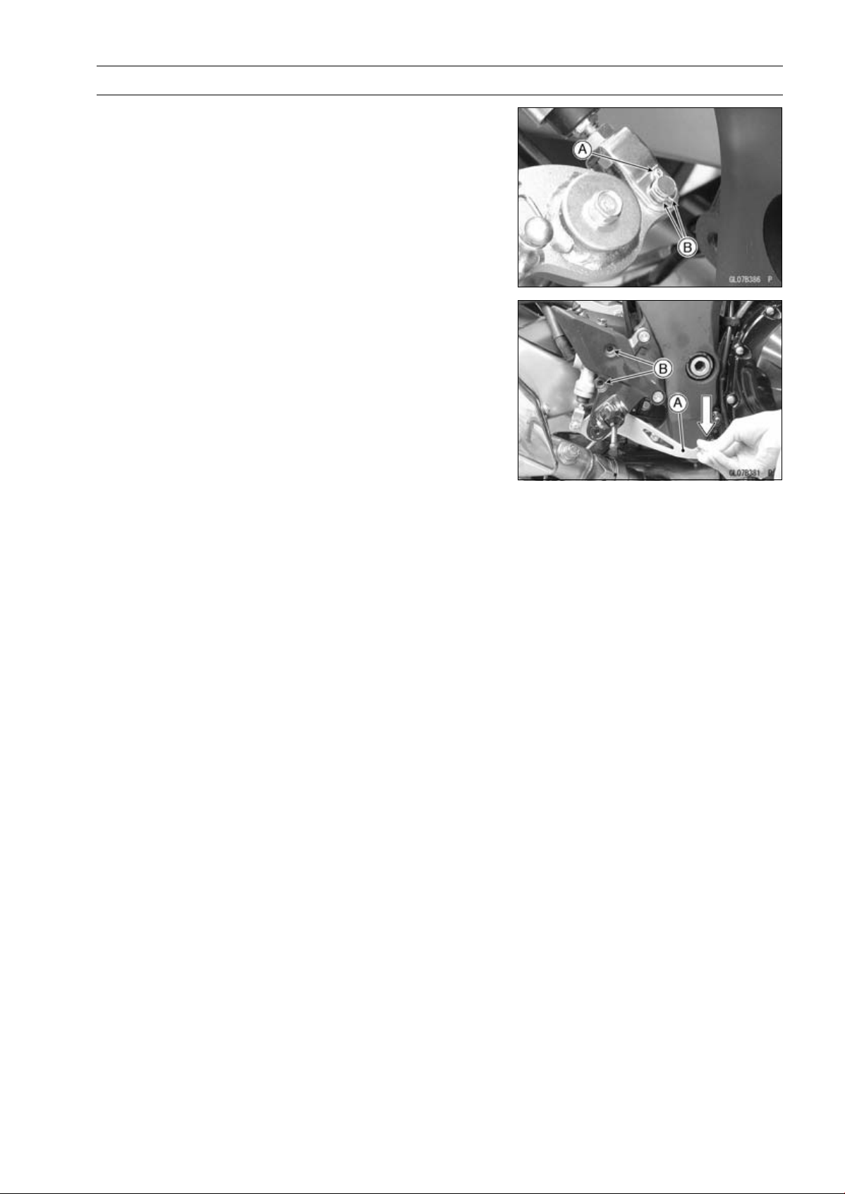
BRAKES 12-21
Master Cylinder
Rear Master Cylinder Installation
•
Replace the cotter pin [A] with a new one.
•
Insert the cotter pin and bend the pin ends [B].
•
Replace the washers on each side of hose fitting with new
ones.
•
Tighten the following bolts.
Torque - Front Footpeg Bracket Bolts: 25 N·m (2.5 kgf·m,
18 ft·lb)
Rear Master Cylinder Mounting Bolts: 25 N·m (2.5
kgf·m, 18 ft·lb)
Brake Hose Banjo Bolts: 25 N·m (2.5 kgf·m, 18
ft·lb)
NOTE
○
Depress the brake pedal [A] and then align the holes [B]
of the master cylinder.
○
After installation, check that the rear brake light switch
spring is hooked on the return spring.
•
Bleed the brake line (see Brake Line Bleeding).
•
Check the brake for good braking power, no brake drag,
and no fluid leakage.
Front Master Cylinder Disassembly
•
Refer to the Master Cylinder Rubber Parts Replacement
in the Periodic Maintenance chapter.
Rear Master Cylinder Disassembly
•
Refer to the Master Cylinder Rubber Parts Replacement
in the Periodic Maintenance chapter.
Master Cylinder Assembly
•
Refer to the Master Cylinder Rubber Parts Replacement
in the Periodic Maintenance chapter.
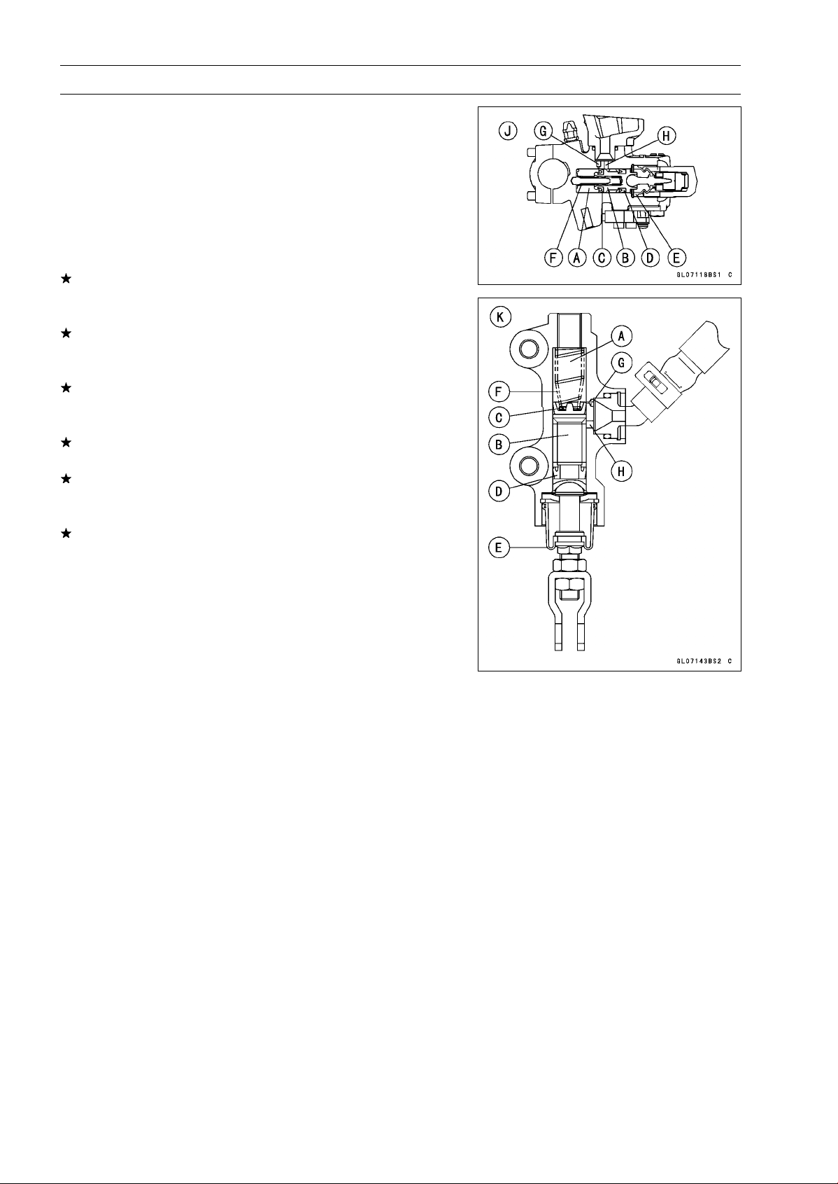
12-22 BRAKES
Master Cylinder
Master Cylinder Inspection (Visual Inspection)
•
Remove the master cylinders (see Front/Rear Master
Cylinder Removal).
•
Disassemble the front and rear master cylinders (see
Master Cylinder Rubber Parts Replacement in the Peri-
odic Maintenance chapter).
•
Check that there are no scratches, rust or pitting on the
inner wall [A] of each master cylinder and on the outside
of each piston [B].
If a master cylinder or piston shows any damage, replace
them.
•
Inspect the primary cup [C] and secondary cup [D].
If a cup is worn, damaged softened (rotted), or swollen,
the piston assembly should be replaced to renew the
cups.
If fluid leakage is noted at the brake lever, the piston as-
sembly should be replaced to renew the cups.
•
Check the dust covers [E] for damage.
If they are damaged, replace them.
•
Check the piston return springs [F] for any damage.
If the springs are damaged, replace them.
•
Check that relief port [G] and supply port [H] are not
plugged.
If the relief port becomes plugged, the brake pads will
drag on the disc. Blow the ports clean with compressed
air.
Front Master Cylinder [J]
Rear Master Cylinder [K]
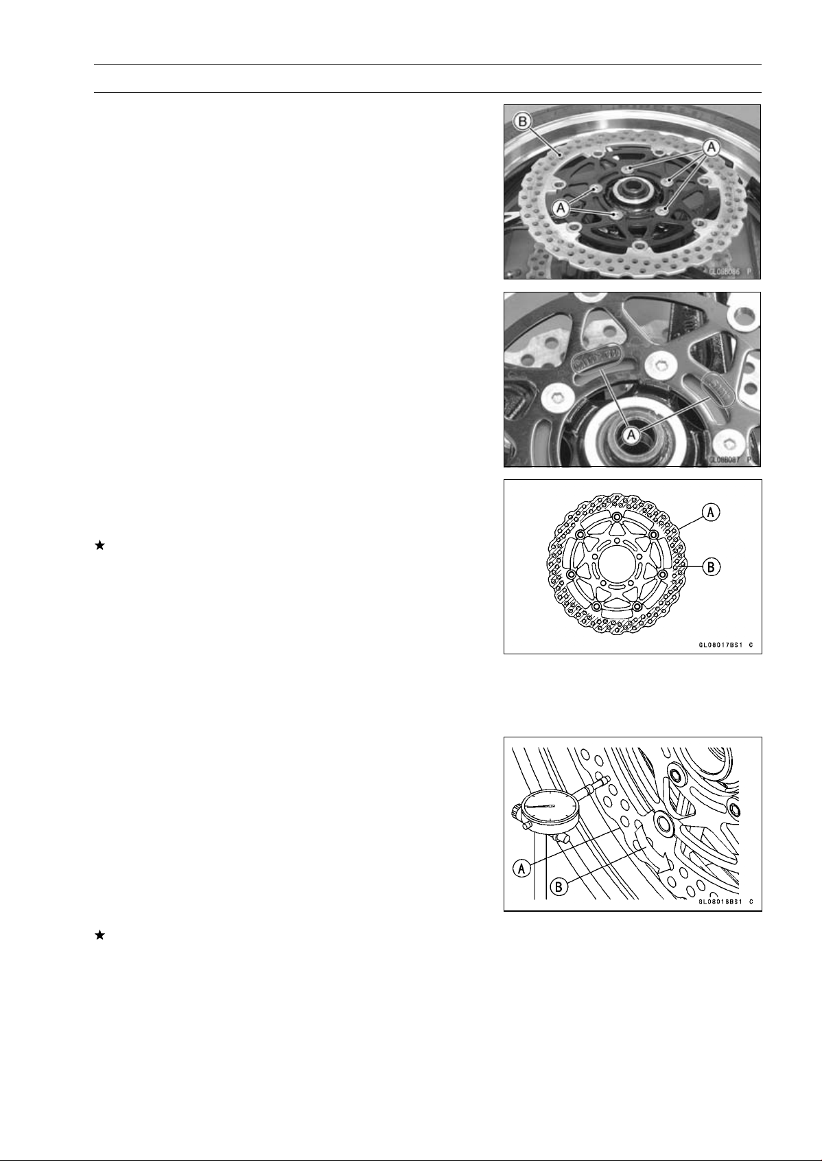
BRAKES 12-23
Brake Disc
Brake Disc Removal
•
Remove the wheels (see Front/Rear Wheel Removal in
the Wheels/Tires chapter).
•
Unscrew the mounting bolts [A], and take off the disc [B].
•
Remove the gaskets.
Brake Disc Installation
•
Replace the gaskets with new ones.
•
Install the brake disc on the wheel so that the marked side
[A] faces out.
•
Apply a non-permanent locking agent to the threads of
the front and rear brake disc mounting bolts, and tighten
them.
Torque - Brake Disc Mounting Bolts: 27 N·m (2.8 kgf·m, 20
ft·lb)
Brake Disc Wear Inspection
•
Measure the thickness of each disc [A] at the point where
it has worn the most.
If the disc has worn past the service limit, replace it.
Measuring Area [B]
Brake Discs Thickness
Standard:
Front
5.3
∼ 5.7 mm (0.21 ∼ 0.22 in.)
Rear
5.8
∼ 6.2 mm (0.23 ∼ 0.24 in.)
Service Limit:
Front
5.0 mm (0.20 in.)
Rear
5.5 mm (0.22 in.)
Brake Disc Warp Inspection
•
Raise the front/rear wheel off the ground.
Special Tools - Jack: 57001-1238
Attachment Jack: 57001-1252
Jack Attachment: 57001-1608
○
For front disc inspection, turn the handlebar fully to one
side.
•
Set up a dial gauge against the disc [A] as shown in
the figure and measure disc runout, while turning [B] the
wheel by hand.
If runout exceeds the service limit, replace the disc.
Disc Runout
Standard: TIR 0.15 mm (0.006 in.) or less
Service Limit: TIR 0.3 mm (0.01 in.)
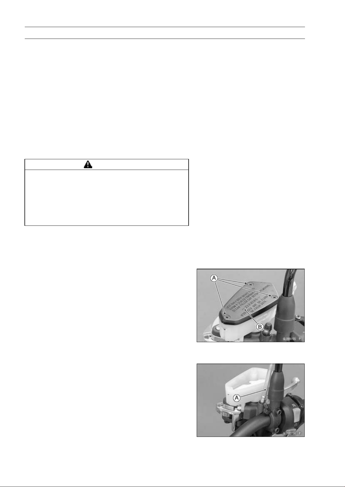
12-24 BRAKES
Brake Fluid
Brake Fluid Level Inspection
•
Refer to the Brake Fluid Level Inspection in the Periodic
Maintenance chapter.
Brake Fluid Change
•
Refer to the Brake Fluid Change in the Periodic Mainte-
nance chapter.
Brake Line Bleeding
The brake fluid has a very low compression coefficient so
that almost all the movement of the brake lever or pedal
is transmitted directly to the caliper for braking action. Air,
however, is easily compressed. When air enters the brake
lines, brake lever or pedal movement will be partially used
in compressing the air. This will make the lever or pedal feel
spongy, and there will be a loss in braking power.
WARNING
Air in the brake lines diminish braking performance
and can cause an accident resulting in injury or
death. If the brake lever or pedal has a soft or
"spongy" feeling mushy when it is applied, there
might be air in the brake lines or the brake may be
defective. Do not operate the vehicle and service
the brake system immediately.
NOTE
○
The procedure to bleed the front brake line is as follows.
Bleeding the rear brake line is the same as for the front
brake.
•
Remove:
Screws [A]
Front Brake Reservoir Cap [B]
Diaphragm Plate
Diaphragm
•
Fill the reservoir with fresh brake fluid to the upper level
line in the reservoir.
•
Slowly pump the brake lever several times until no air
bubbles can be seen rising up through the fluid from the
holes at the bottom of the reservoir.
○
Bleed the air completely from the master cylinder by this
operation.
•
Remove the rubber cap from the bleed valve on the front
master cylinder.
•
Attach a clear plastic hose [A] to the bleed valve, and run
the other end of the hose into a container.
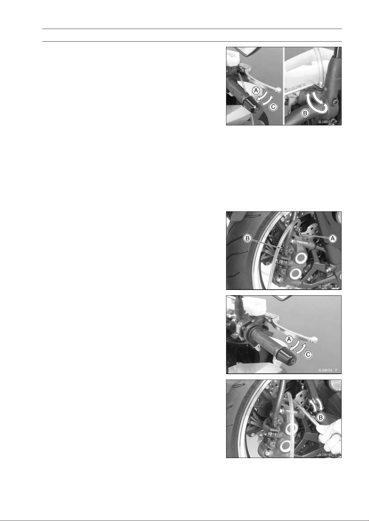
BRAKES 12-25
Brake Fluid
•
Bleed the brake line and the master cylinder.
○
Repeat this operation until no more air can be seen com-
ing out into the plastic hose.
1. Pump the brake lever until it becomes hard, and apply
the brake and hold it [A].
2. Quickly open and close [B] the bleed valve while hold-
ing the brake applied.
3. Release the brake [C].
NOTE
○
The fluid level must be checked often during the bleed-
ing operation and replenished with fresh brake fluid as
necessary. If the fluid in the reservoir runs completely
out any time during bleeding, the bleeding operation
must be done over again from the beginning since air
will have entered the line.
•
Remove the clear plastic hose.
•
Tighten the bleed valve, and install the rubber cap.
Torque - Front Master Cylinder Bleed Valve: 7.8 N·m (0.80
kgf·m, 69 in·lb)
•
Remove the rubber cap [A] from the bleed valve on the
caliper.
•
Attach a clear plastic hose [B] to the bleed valve, and run
the other end of the hose into a container.
•
Bleed the brake line and the caliper.
○
Repeat this operation until no more air can be seen com-
ing out into the plastic hose.
1. Pump the brake lever until it becomes hard, and apply
the brake and hold it [A].
2. Quickly open and close [B] the bleed valve while hold-
ing the brake applied.
3. Release the brake [C].
NOTE
○
The fluid level must be checked often during the bleed-
ing operation and replenished with fresh brake fluid as
necessary. If the fluid in the reservoir runs completely
out any time during bleeding, the bleeding operation
must be done over again from the beginning since air
will have entered the line.
○
Tap the brake hose lightly from the caliper to the reser-
voir for more complete bleeding.
○
Front Brake: First bleeding the right caliper then repeat
the above steps for the left caliper.
•
Remove the clear plastic hose.
•
Install:
Diaphragm
Diaphragm Plate
Front Brake Reservoir Cap
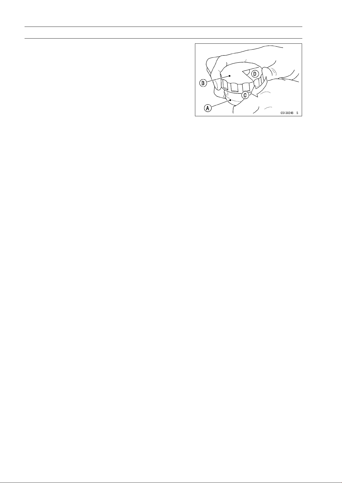
12-26 BRAKES
Brake Fluid
•
Follow the procedure below to install the rear brake fluid
reservoir cap correctly.
○
First, tighten the brake fluid reservoir cap [B] clockwise
[C] by hand until slight resistance is felt indicating that
the cap is seated on the reservoir body, then tighten the
cap an additional 1/6 turn [D] while holding the brake fluid
reservoir body [A].
•
Tighten the rear brake reservoir cap stopper screw se-
curely.
•
Tighten:
Torque - Front Master Cylinder Reservoir Cap Screws: 1.5
N·m (0.15 kgf·m, 13 in·lb)
•
Tighten the bleed valve, and install the rubber cap.
Torque - Bleed Valves: 7.8 N·m (0.80 kgf·m, 69 in·lb)
•
Check the fluid level (see Brake Fluid Level Inspection in
the Periodic Maintenance chapter).
•
After bleeding is done, check the brake for good braking
power, no brake drag, and no fluid leakage.

BRAKES 12-27
Brake Fluid
WARNING
When working with the disc brake, observe the pre-
cautions listed below.
1. Never reuse old brake fluid.
2. Do not use fluid from a container that has been
left unsealed or that has been open for a long
time.
3. Do not mix two types and brands of fluid for use
in the brake. This lowers the brake fluid boiling
point and could cause the brake to be ineffec-
tive. It may also cause the rubber brake parts to
deteriorate.
4. Don’t leave the reservoir cap off for any length
of time to avoid moisture contamination of the
fluid.
5. Don’t change the fluid in the rain or when a
strong wind is blowing.
6. Except for the disc pads and disc, use only disc
brake fluid, isopropyl alcohol, or ethyl alcohol
for cleaning of the brake parts. Do not use any
other fluid for cleaning these parts. Gasoline,
engine oil, or any other petroleum distillate will
cause deterioration of the rubber parts. Oil
spilled on any part will be difficult to wash off
completely and will eventually deteriorate the
rubber used in the disc brake.
7. When handling the disc pads or disc, be careful
that no disc brake fluid or any oil gets on them.
Clean off any fluid or oil that inadvertently gets
on the pads or disc with a high flash-point sol-
vent. Do not use one which will leave an oily
residue. Replace the pads with new ones if they
cannot be cleaned satisfactorily.
8. Brake fluid quickly ruins painted surfaces; any
spilled fluid should be completely wiped up im-
mediately.
9. If any of the brake line fittings or the bleed valve
is opened at any time, the AIR MUST BE BLED
FROM THE BRAKE LINE.

12-28 BRAKES
Brake Hose
Brake Hose Removal/Installation
•
Refer to the Brake Hose Replacement in the Periodic
Maintenance chapter.
Brake Hose and Pipe Inspection
•
Refer to the Brake Hose and Pipe Damage and Instal-
lation Condition Inspection in the Periodic Maintenance
chapter.
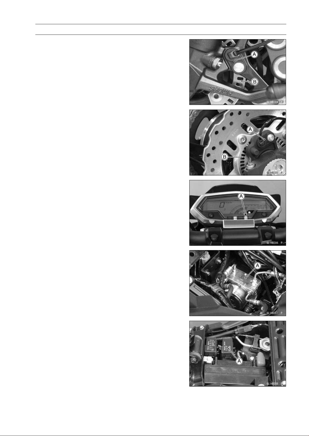
BRAKES 12-29
Anti-Lock Brake System (Equipped Models)
Parts Location
Front Wheel Rotation Sensor [A]
Front Wheel Rotation Sensor Rotor [B]
Rear Wheel Rotation Sensor [A]
Rear Wheel Rotation Sensor Rotor [B]
ABS Indicator Light [A]
ABS Hydraulic Unit [A]
ABS Fuse Box [A]
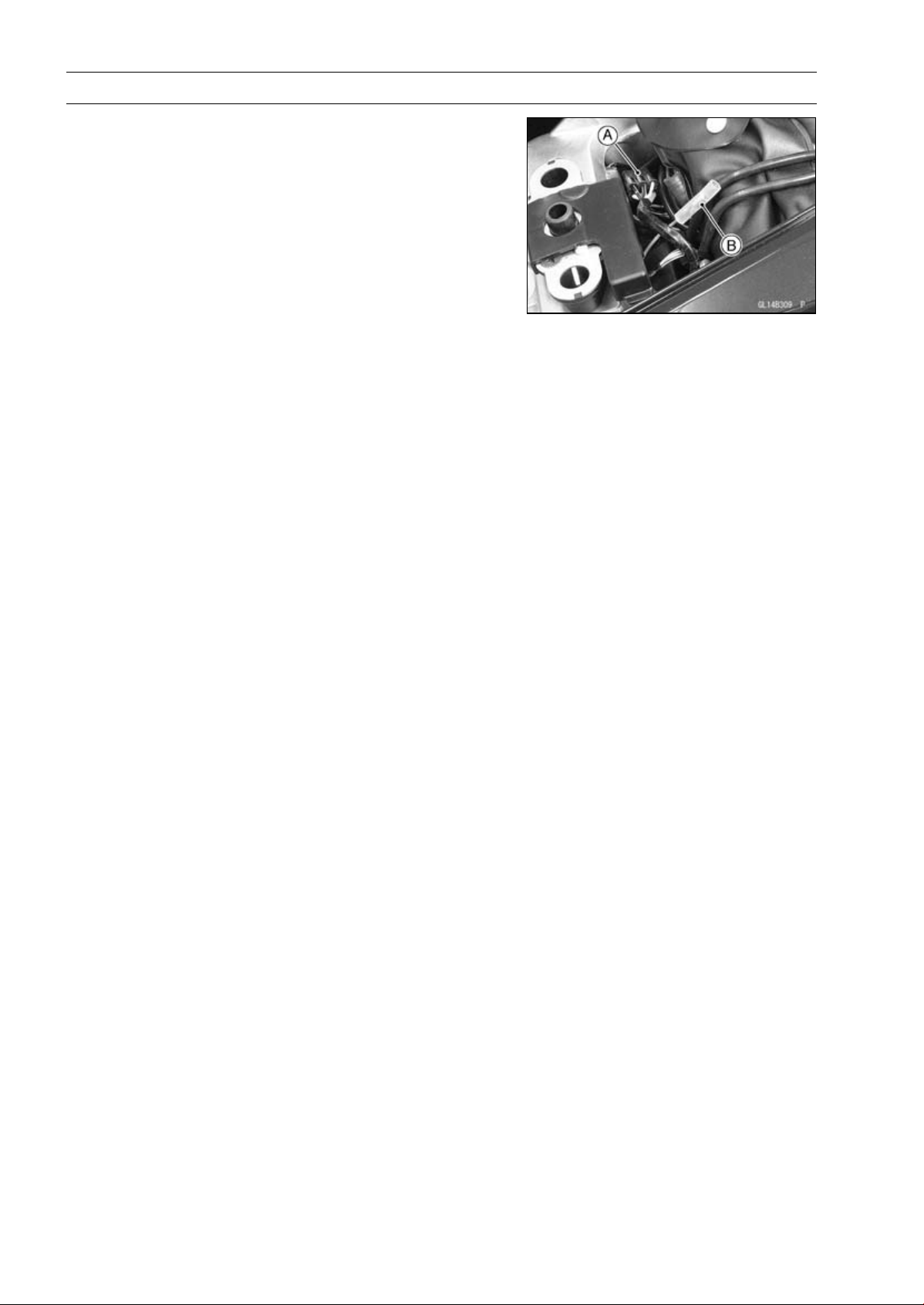
12-30 BRAKES
Anti-Lock Brake System (Equipped Models)
ABS Kawasaki Diagnostic System Connector [A]
ABS Self-diagnosis Terminal [B]
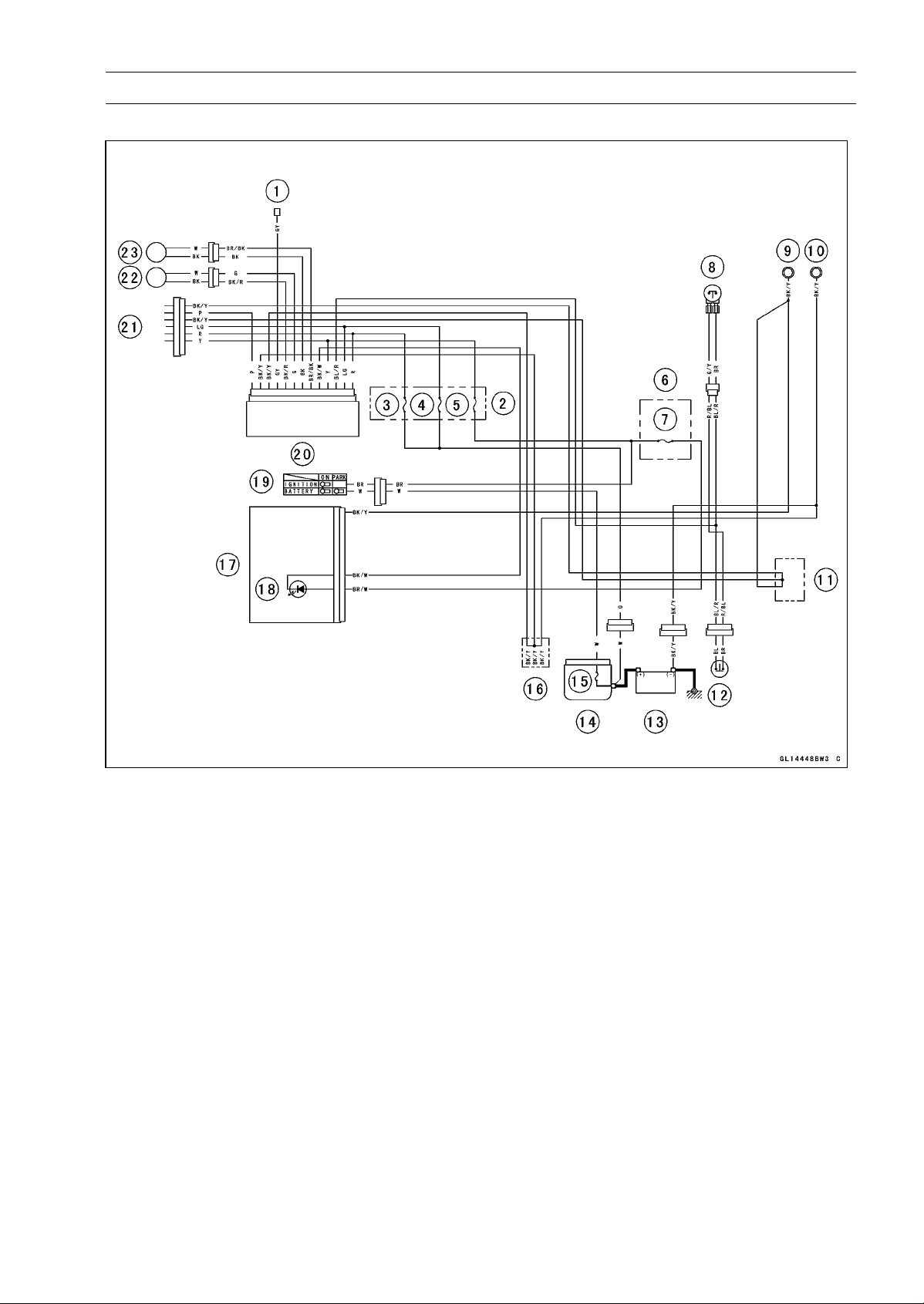
BRAKES 12-31
Anti-Lock Brake System (Equipped Models)
ABS System Wiring Diagram
1. ABS Self-diagnosis Terminal
2. ABS Fuse Box
3. ABS Motor Relay Fuse 30 A
4. ABS Solenoid Valve Relay Fuse 20 A
5. ABS ECU Fuse 10 A
6. Fuse Box
7. Ignition Fuse 10 A
8. Front Brake Light Switch
9. Meter Ground
10. Frame Ground
11. Water-proof Joint C
12. Rear Brake Light Switch
13. Battery 12 V 8 Ah
14. Starter Relay
15. Main Fuse 30 A
16. Water-proof Joint D
17. Meter Unit
18. ABS Indicator Light (LED)
19. Ignition Switch
20. ABS Hydraulic Unit
21. ABS Kawasaki Self-diagnosis System Con-
nector
22. Front Wheel Rotation Sensor
23. Rear Wheel Rotation Sensor
○
Color Codes:
BK: Black
BL: Blue
BR: Brown
CH: Chocolate
DG: Dark Green
G: Green
GY: Gray
LB: Light Blue
LG: Light Green
O: Orange
P: Pink
PU: Purple
R: Red
V: Violet
W: White
Y: Yellow
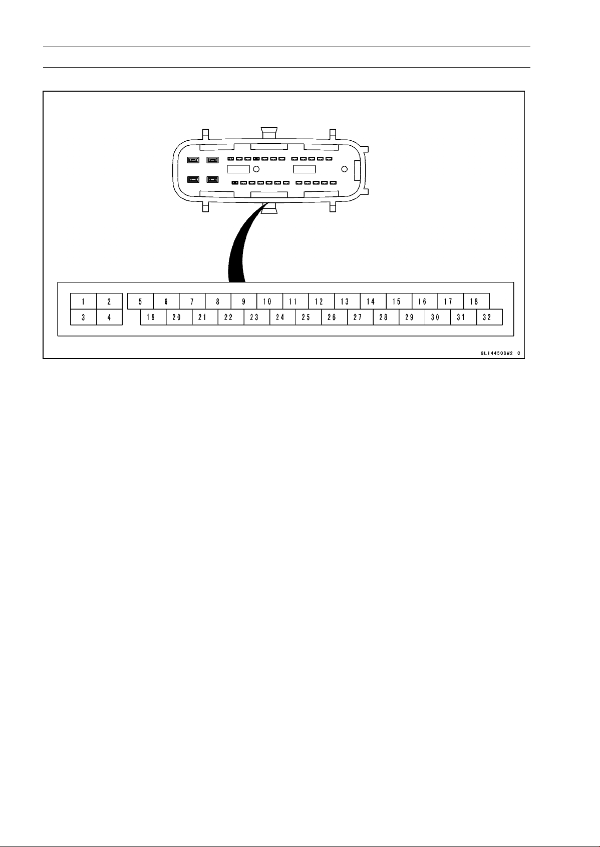
12-32 BRAKES
Anti-Lock Brake System (Equipped Models)
ABS Hydraulic Unit Terminal Names
1. Power Supply to ABS Motor
2. Power Supply to ABS Solenoid Valve Relay
3. Ground
4. Ground
5. ABS Self-diagnosis Terminal
6. Unused
7. Unused
8. Front and Rear Brake Light Switch
9. Unused
10. Unused
11. Unused
12. Unused
13. Unused
14. Unused
15. Unused
16. Power Supply
17. Unused
18. Unused
19. Unused
20. Unused
21. Unused
22. Unused
23. Power Supply to Front Wheel Rotation Sensor
24. ABS Kawasaki Self-diagnosis System Terminal
25. ABS Indicator Light (LED)
26. Power Supply to Rear Wheel Rotation Sensor
27. Front Wheel Rotation Sensor Signal
28. Unused
29. Unused
30. Rear Wheel Rotation Sensor Signal
31. Unused
32. Unused

BRAKES 12-33
Anti-Lock Brake System (Equipped Models)
ABS Servicing Precautions
There are a number of important precautions that should
be followed servicing the ABS system.
○
This ABS system is designed to be used with a 12 V
sealed battery as its power source. Do not use any
other battery except for a 12 V sealed battery as a power
source.
○
Do not reverse the battery cable connections. This will
damage the ABS hydraulic unit.
○
To prevent damage to the ABS parts, do not disconnect
the battery cables or any other electrical connections
when the ignition switch is ON or while the engine is
running.
○
Take care not to short the leads that are directly con-
nected to the battery positive (+) terminal to the chassis
ground.
○
Do not turn the ignition switch ON while any of the ABS
electrical connectors are disconnected. The ABS hy-
draulic unit memorizes service codes.
○
Do not spray water on the electrical parts, ABS parts, con-
nectors, leads and wiring.
○
If a transceiver is installed on the motorcycle, make sure
that the operation of the ABS system is not influenced
by electric wave radiated from the antenna. Locate the
antenna as far as possible away from the ABS hydraulic
unit.
○
Whenever the ABS electrical connections are to be dis-
connected, first turn off the ignition switch.
○
The ABS parts should never be struck sharply, as with
a hammer, or allowed to fall on a hard surface. Such a
shock to the parts can damage them.
○
The ABS parts cannot be disassembled. Even if a fault is
found, do not try to disassemble and repair the ABS parts,
replace it.
○
The ABS has many brake lines, pipes, and leads. And
the ABS cannot detect problems with the conventional
braking system (brake disc wear, unevenly worn brake
pad, and other mechanical faults). To prevent trouble,
check the brake lines and pipes for correct routing and
connection, the wiring for correct routing, and the brakes
for proper braking power. Be sure to check for fluid leak-
age, and bleed the brake line thoroughly.
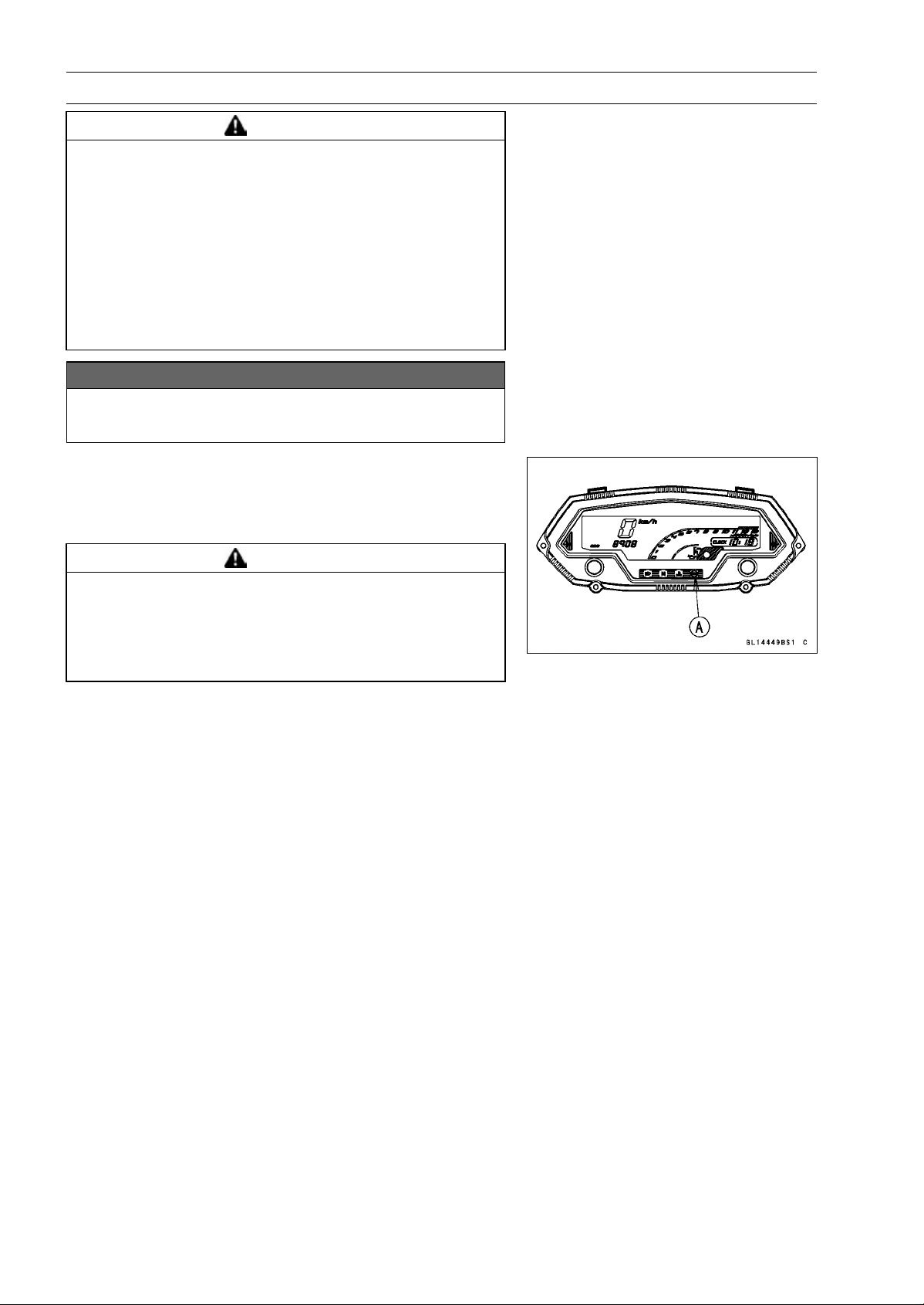
12-34 BRAKES
Anti-Lock Brake System (Equipped Models)
WARNING
Air in the brake lines diminish braking performance
and can cause an accident resulting in injury or
death. If any of the brake line fittings, including the
ABS hydraulic unit joint nuts, or the bleed valve is
opened at any time, the air must be bled completely
from the brake line. If the brake lever has a soft
or "spongy" feeling mushy when it is applied, there
might be air in the brake lines or the brake may be
defective. Do not operate the vehicle and service
the brake system immediately.
NOTICE
Do not ride the motorcycle with air in the brake line,
or the ABS could malfunction.
○
The ABS indicator light (LED) [A] may light if the tire pres-
sure is incorrect, a non-recommended tire is installed, or
the wheel is deformed. If the indicator light lights, remedy
the problem and clear the service code.
WARNING
Use of non-recommended tires may cause malfunc-
tioning of ABS and can lead to extended braking
distance resulting in an accident causing serious
injury or death. Always use recommended stan-
dard tires for this motorcycle.
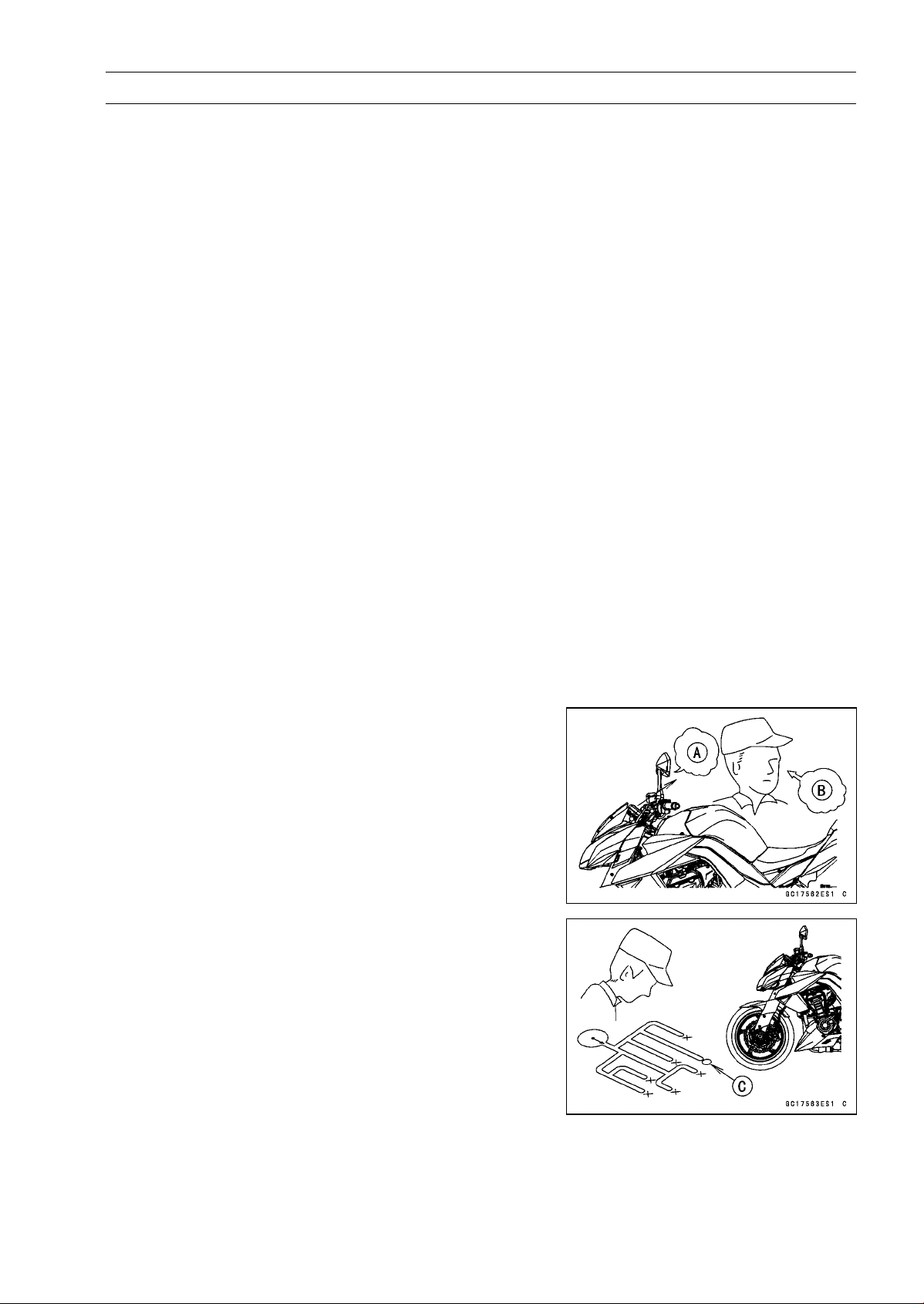
BRAKES 12-35
Anti-Lock Brake System (Equipped Models)
○
The ABS indicator light (LED) may come on if the engine
is run with the motorcycle on its stand and the transmis-
sion in gear. If the indicator light comes on, just turn the
ignition switch OFF, then clear service code 42, which in-
dicates a “Faulty front wheel rotation sensor”.
○
When the ABS operates, the ABS makes noise and the
rider feels the reaction force on the brake lever and brake
pedal. This is a normal condition. It informs the rider that
the ABS is operating normally.
○
Service codes detected once by the ABS hydraulic unit
will be memorized in the ABS hydraulic unit. Therefore,
after maintenance work is finished, be sure to erase the
service codes. Do not erase the service codes during
troubleshooting. Wait until all the checks and repair work
are finished to prevent duplication of previous service
codes and unnecessary maintenance work.
○
Before delivering the motorcycle to the customer, be
sure to erase any service codes which might be stored in
the ABS hydraulic unit. Using the self-diagnosis feature,
make sure that the ABS indicator light (LED) lights. A
fully charged battery is a must for conducting reliable
self-diagnosis. Test run the motorcycle at a speed of
more than 20 km/h (12 mph) to see that the ABS indicator
light (LED) does not come on. Finally, test run the mo-
torcycle at a speed of more than 30 km/h (20 mph) and
brake suddenly to see that the motorcycle stops without
loss of steering control and the ABS operates normally
(The reaction force generated is felt in the brake lever
and pedal.). This completes the final inspection.
ABS Troubleshooting Outline
When an abnormality in the system occurs, the ABS in-
dicator light (LED) lights up to alert the rider. In addition,
the nature of the fault is stored in the memory of the ABS
hydraulic unit and when in the self-diagnosis mode, the ser-
vice code [A] is indicated by the number of times the ABS
indicator light (LED) blinks. The service codes stored in
memory are not erased until the mode has been changed
to the fault erase mode after the fault has been corrected.
Therefore, after correcting the problem, always erase the
service codes and then run the self-diagnosis program to
confirm normal signal output. When, due to a malfunction,
the ABS indicator light (LED) remains lit, get a thorough
understanding of the background before starting the repair
work. Ask the rider about the conditions [B] under which
the problem occurred and try to determine the cause [C].
Do not rely solely on the ABS self-diagnosis function, use
common sense; check the brakes for proper braking power,
and brake fluid level, search for leaks, etc.
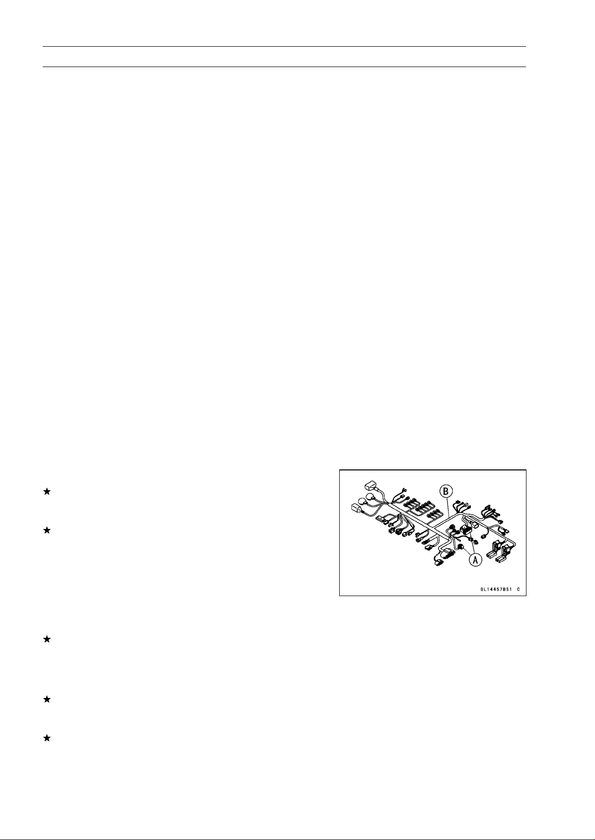
12-36 BRAKES
Anti-Lock Brake System (Equipped Models)
Even when the ABS is operating normally, the ABS indi-
cator light (LED) may light up under the conditions listed be-
low. Turn the ignition switch OFF to stop the indicator light.
If the motorcycle runs without erasing the service code, the
light may light up again.
○
After continuous riding on a rough road.
○
When the engine is started with the stand raised and the
transmission engaged, and the rear wheel turns.
○
When accelerating so abruptly that the front wheel leaves
the ground.
○
When the ABS has been subjected to strong electrical
interference.
○
When tire pressure is abnormal. Adjust tire pressure.
○
When a tire different in size from the standard size is being
used. Replace with standard size.
○
When the wheel is deformed. Replace the wheel.
Much of the ABS troubleshooting work consists of con-
firming continuity of the wiring. The ABS parts are assem-
bled and adjusted by the manufacturer, so there is no need
to disassemble or repair them. Replace the ABS hydraulic
unit.
The basic troubleshooting procedures are listed below.
•
Carry out pre-diagnosis inspections as a preliminary in-
spection.
•
Determine the fault using the self-diagnosis function.
•
Check wiring and connections from the ABS hydraulic
unit connector to the suspected faulty ABS part, using the
hand tester.
Special Tool - Hand Tester: 57001-1394
•
Visually inspect the wiring for signs of burning or fraying.
If any wiring is poor, replace the damaged wiring.
•
Pull each connector [A] apart and inspect it for corrosion,
dirt and damage.
If the connector is corroded or dirty, clean it carefully. If it
is damaged, replace it.
•
Check the wiring for continuity.
○
Use the wiring diagram to find the ends of the lead which
is suspected of being a problem.
○
Connect the hand tester between the ends of the leads.
Special Tool - Hand Tester: 57001-1394
○
Set the tester to the × 1 Ω range, and read the tester.
If the tester does not read 0 Ω, the lead is defective. Re-
place the main harness [B] if necessary.
•
Narrow down suspicious parts and close in on the faulty
ABS part by repeating the continuity tests.
If no abnormality is found in the wiring or connectors, the
ABS parts are the next likely suspects. Check each part
one by one.
If an abnormality is found, replace the affected ABS part.
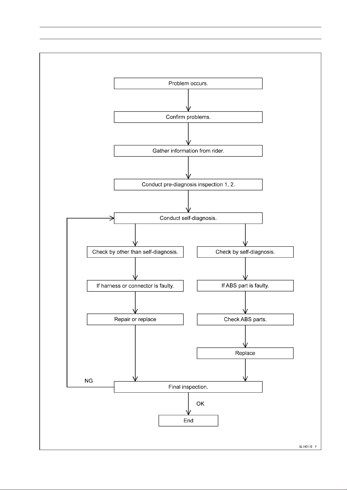
BRAKES 12-37
Anti-Lock Brake System (Equipped Models)
ABS Diagnosis Flow Chart
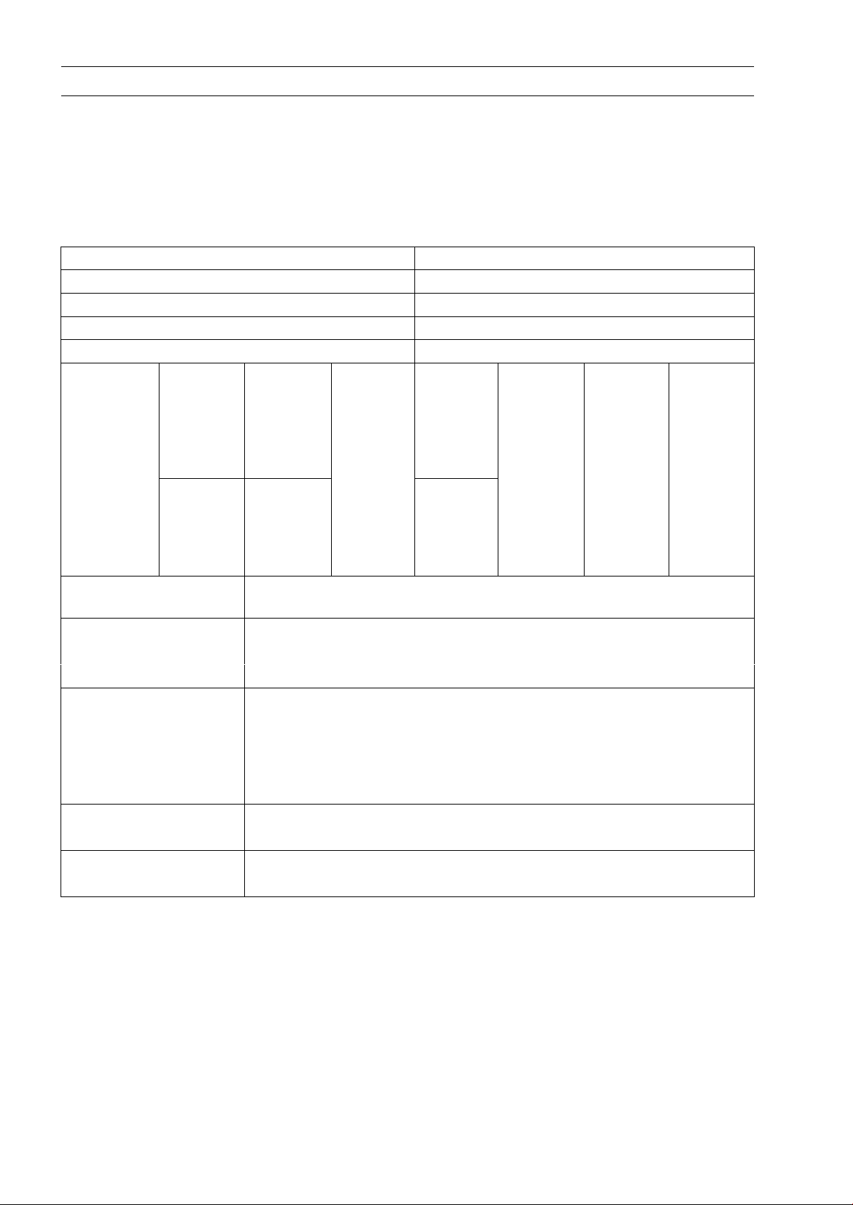
12-38 BRAKES
Anti-Lock Brake System (Equipped Models)
Inquiries to Rider
○
Each rider reacts to problems in different ways, so it is important to confirm what kind of condition
the rider is dissatisfied with.
○
Try to find out exactly what problem occurs under exactly what conditions by asking the rider; know-
ing this information may help you reproduce the problem in the shop.
○
The diagnosis sheet will help prevent you from overlooking any keys, so always use it.
Sample Diagnosis Sheet
Rider name: Registration No. (license plate No.):
Year of initial registration: Model:
Engine No.: Frame No.:
Date problem occurred: Frequency:
Weather: Mileage:
□ Brake
lever
vibration
or noise
□ Indicator
light
blinks
□ □ Abnor-
mal
brake
lever
move-
ment
□ □ □
Phenome-
non
□ Pedal
vibration
or noise
□ Indicator
light
remains
lit up
Braking
distance
too long
□ Abnor-
mal
pedal
move-
ment
ABS not
working
ABS
works
but
indicator
light
doesn’t
light up
ABS op-
erating
too fre-
quently
Engine condition
sat
problem
□ At start-up □
After starting
□
At 5 000 r/min (rpm)
or more
Road conditions □
Slippery road (□
snow, □ gravel, □ other
)
□
Rough surface
□
Other
Driving conditions □High-speed cornering
□
Driving 10 km/h (6 mph) or above
□
Driving below 10 km/h (6 mph)
□ When stopping
□ When turning
Brake application □ Gradual
□ Abrupt
Other conditions □ Large brake lever stroke
□ Large pedal stroke
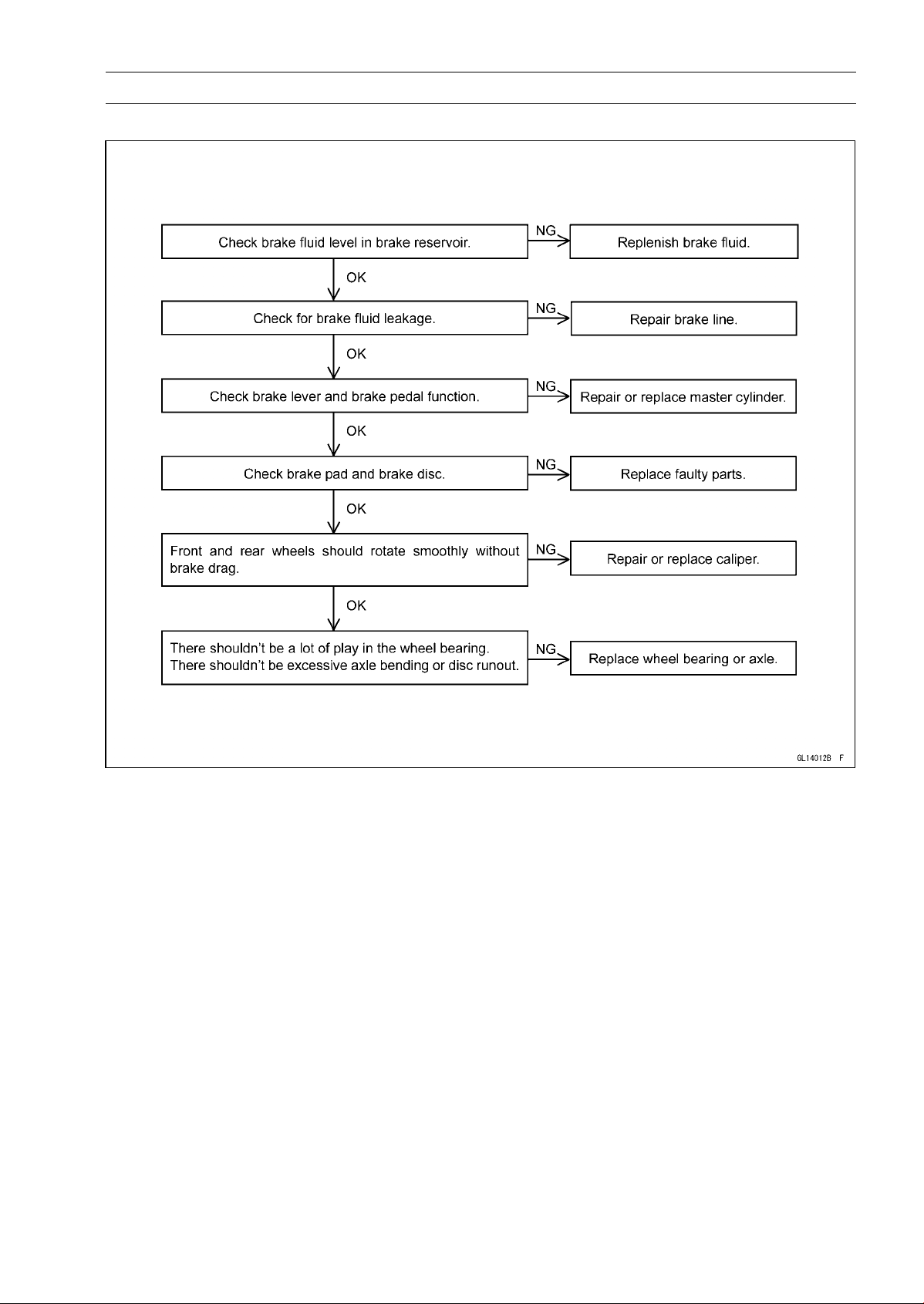
BRAKES 12-39
Anti-Lock Brake System (Equipped Models)
Pre-Diagnosis Inspection 1
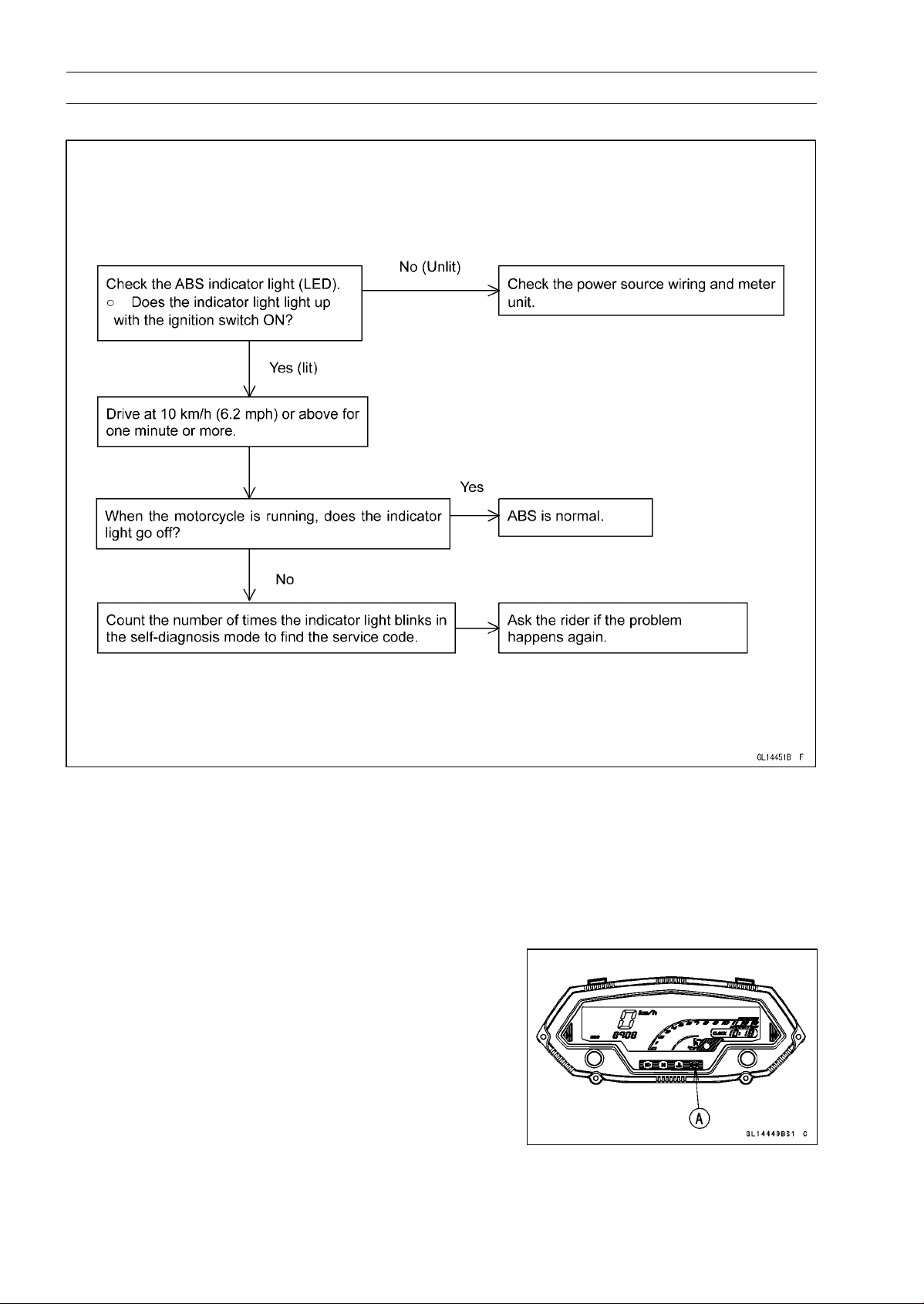
12-40 BRAKES
Anti-Lock Brake System (Equipped Models)
Pre-Diagnosis Inspection 2
Self-diagnosis Outline
When the indicator light has blinked or come on, the ABS hydraulic unit memorizes and stores the
service code (17 codes including “Normal Code”) for the service person to troubleshoot easily. The
service code memory is powered directly by the battery and cannot be canceled by the ignition switch.
The ABS hydraulic unit can memorize up to all service codes (17 codes). Further service codes are
memorized after erasing the preceding all service codes (17 codes). If there is no fault, only the start
code 12 is shown, indicating that “The ABS is normal”.
Self-diagnosis Procedures
○
When a problem occurs with the ABS system, the ABS
indicator light (LED) [A] lights.
NOTE
○
Use a fully charged battery when conducting
self-diagnosis. Otherwise, the light blinks very slowly
or doesn’t blink.
○
The motorcycle is stopped.
○
Keep the self-diagnosis terminal grounded during self
-diagnosis, with an auxiliary lead.
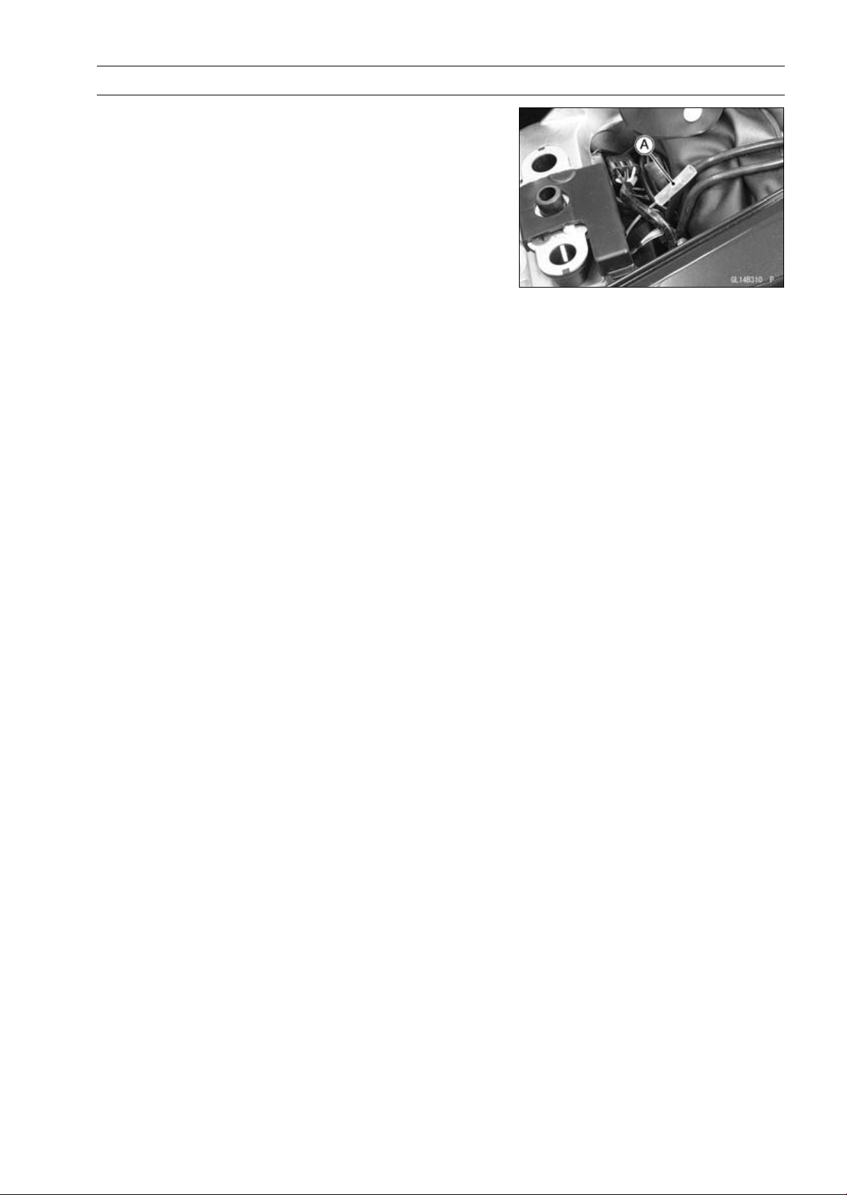
BRAKES 12-41
Anti-Lock Brake System (Equipped Models)
•
Remove the rear seat (see Rear Seat Removal in the
Frame chapter).
•
Turn on the ignition switch.
•
Ground the self-diagnosis terminal [A] (Gray) to the bat-
tery (–) terminal, using a suitable lead.
○
Count the blinks of the light to read the service code.
Keep the auxiliary lead ground until you finish reading the
service code.
Service Code Clearing Procedures
•
Start the service code erase mode with the following pro-
cedure.
○
The erase mode starts when the ABS self-diagnosis ter-
minal is disconnected from the ground terminal after start-
ing the self-diagnosis mode.
○
The service code can be erased by grounding and un-
grounding (each time for at least one second) the ABS
self-diagnosis terminal three times within about 12.5 sec-
onds after starting the erase mode.
○
The ABS indicator light (LED) remains lit during the erase
mode.
○
After erasing, the ABS indicator light (LED) blinks and
lights.
○
Once erasing is finished, enter the self-diagnosis mode
again to confirm that the service codes have been
erased. If the ABS has been reset and all codes have
been erased, only start code 12 will be shown.
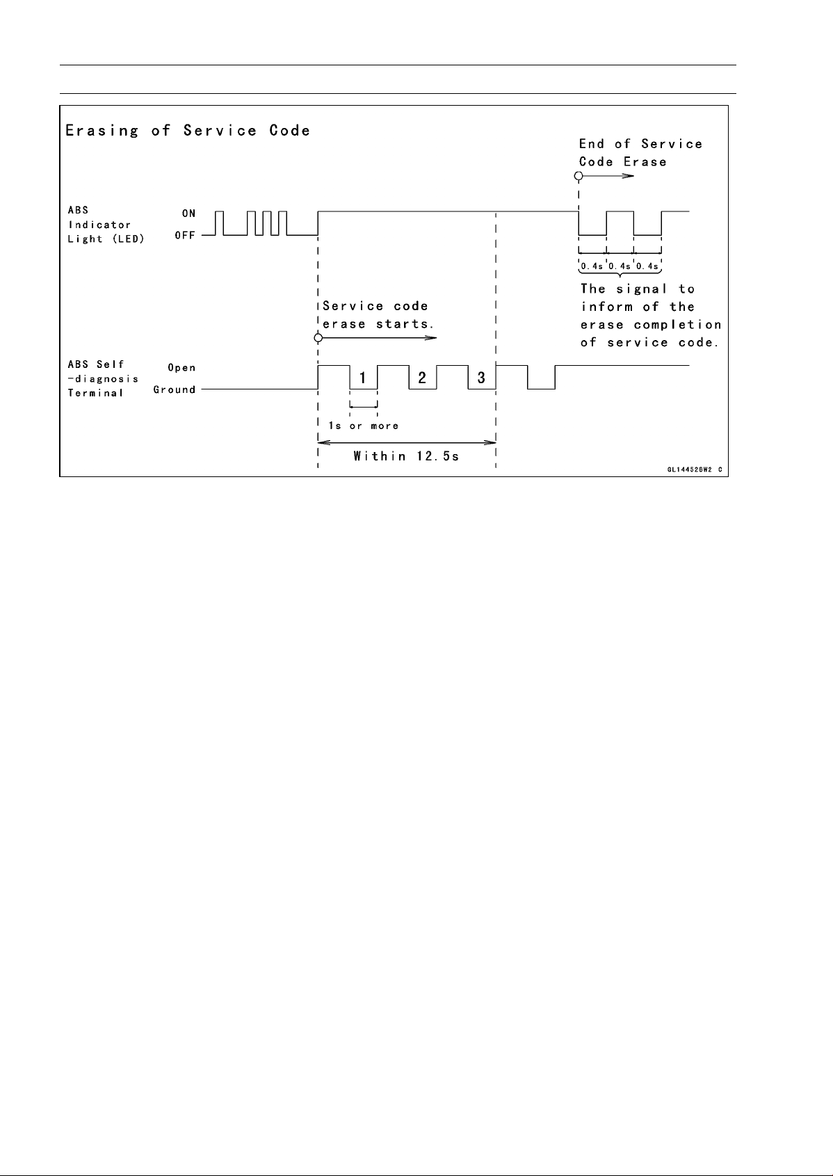
12-42 BRAKES
Anti-Lock Brake System (Equipped Models)
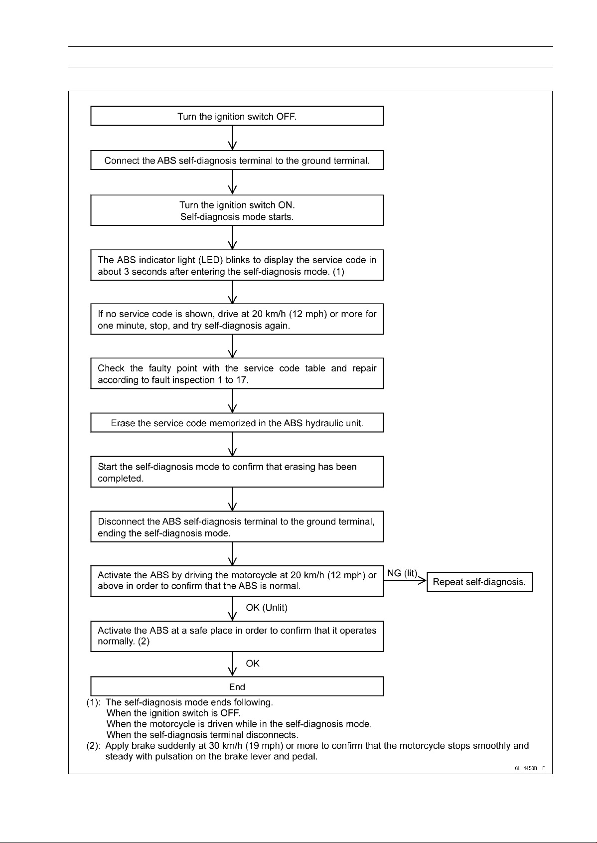
BRAKES 12-43
Anti-Lock Brake System (Equipped Models)
Self-diagnosis Flow Chart
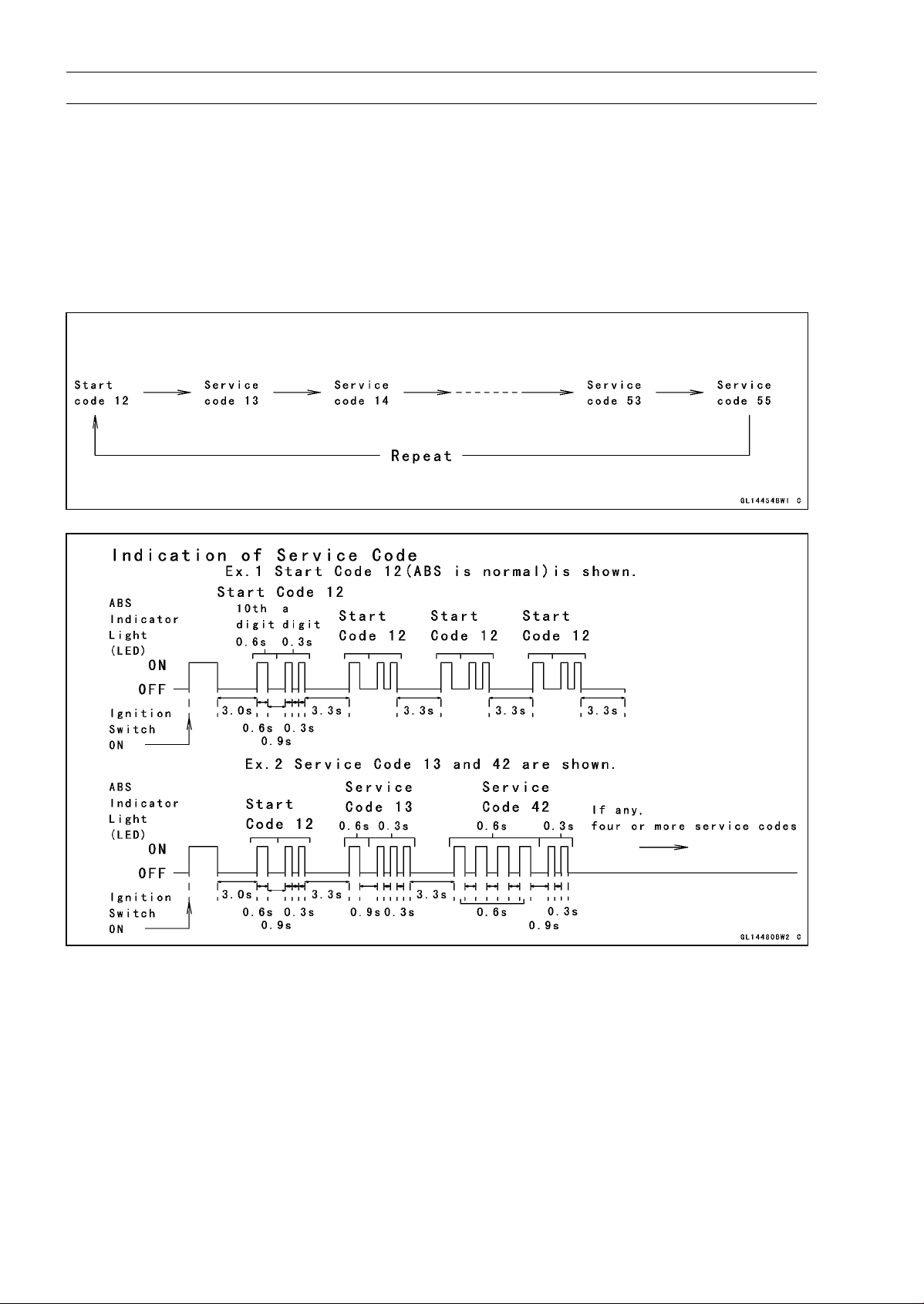
12-44 BRAKES
Anti-Lock Brake System (Equipped Models)
How to Read Service Codes
○
Service codes are shown by a series of long and short blinks of the ABS indicator light (LED) as
shown below.
○
Read 10th digit and unit digit as the ABS indicator light (LED) blinks.
○
When there are a number of faults, a maximum of all service codes (17 codes) can be stored and
the display will begin starting from the small number code entered.
○
For the display pattern, first the smallest number code is shown, next up to all service codes (17
codes) starting with the last one stored, then the display is repeated from the smallest number code
once again.
○
If there is no fault, the ABS indicator light (LED) lights as shown in the figure.
How to Erase Service Codes
○
Even if the ignition switch is turned OFF, the battery or the ABS hydraulic unit are disconnected, all
service codes remain in the ABS hydraulic unit.
○
Refer to the Service Code Clearing Procedure for the service code erasure.
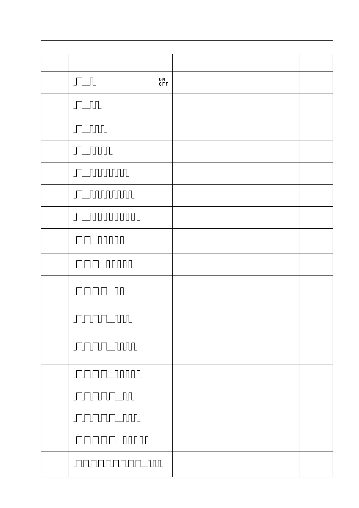
BRAKES 12-45
Anti-Lock Brake System (Equipped Models)
Service Code Table
Service
Code
ABS Indicator Light (LED) Problems
Light
State
11
Rise in heat of solenoid coil by ABS
continuousness operation
ON
12 Start code (not fault)
After
starts,
turn off
13
Rear inlet solenoid valve trouble (shorted
or open, stuck valve)
ON
14
Rear outlet solenoid valve trouble (shorted
or open, stuck valve)
ON
17
Front inlet solenoid valve trouble (shorted
or open, stuck valve)
ON
18
Front outlet solenoid valve trouble (shorted
or open, stuck valve)
ON
19
ABS solenoid valve relay trouble (wiring
shorted or open, stuck relay)
ON
25
Front, rear tire abnormal (substandard
tire, deformation wheel, sensor rotor teeth
number wrong)
ON
35
ABS motor relay trouble (wiring shorted,
open or lock, stuck relay)
ON
42
Front wheel rotation sensor signal
abnormal (sensor or rotor missing, too
large clearance, rotor tooth worn or
missing)
ON
43
Front wheel rotation sensor wiring
abnormal (wiring shorted or open)
ON
44
Rear wheel rotation sensor signal
abnormal (sensor or rotor missing, too
large clearance, rotor tooth worn or
missing)
ON
45
Rear wheel rotation sensor wiring
abnormal (wiring shorted or open)
ON
52
Power supply voltage abnormal
(low-voltage)
ON
53
Power supply voltage abnormal
(low-voltage)
ON
55
ECU trouble (ECU operation abnormal) ON
93
Wheel rotation sensor signal abnormal
(too high speed, special road running,
substandard tire)
ON
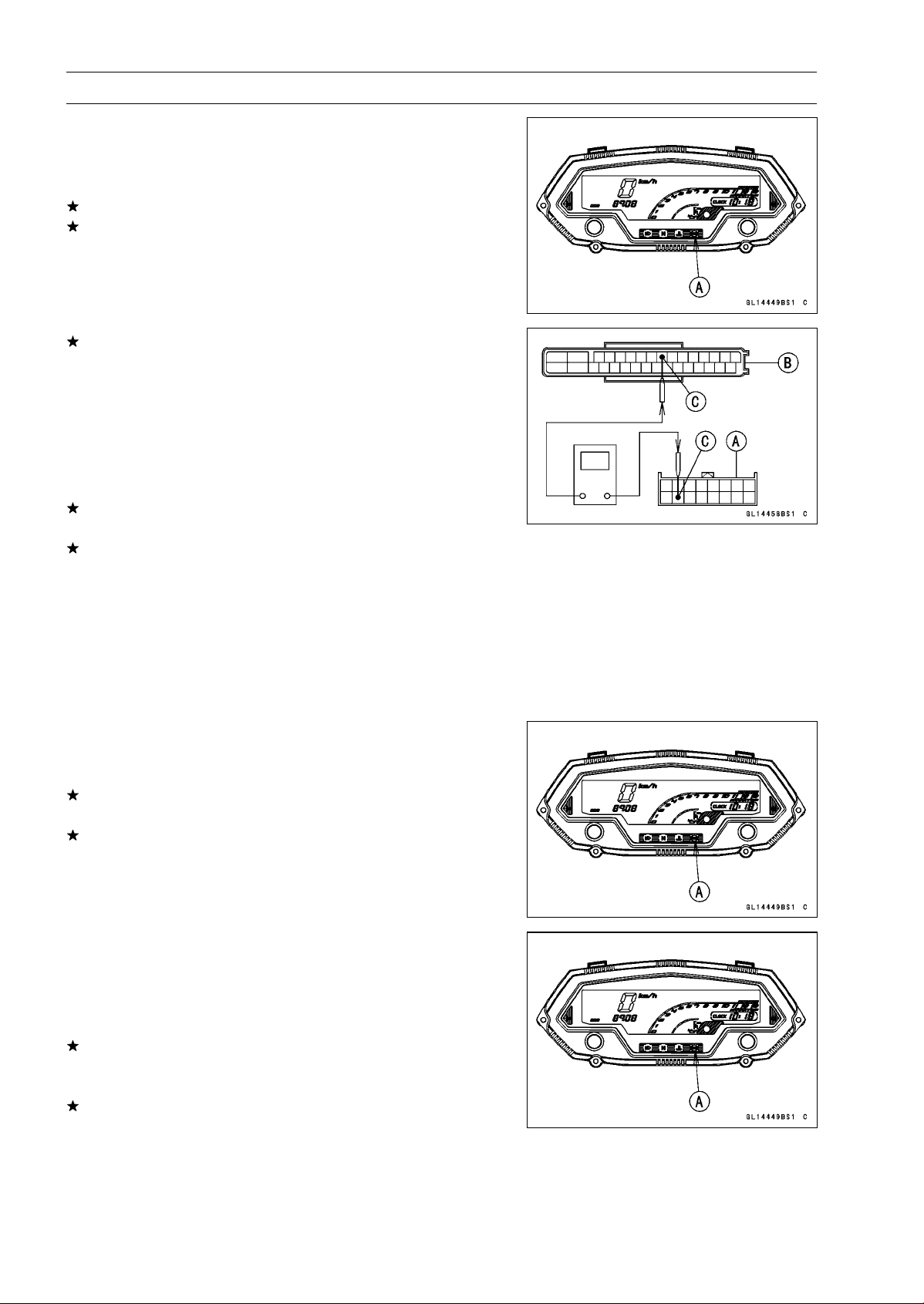
12-46 BRAKES
Anti-Lock Brake System (Equipped Models)
ABS Indicator Light (LED) Inspection
○
In this model, the ABS indicator light (LED) [A] goes on or
blinks by the control of the ABS hydraulic unit.
•
Turn the ignition switch ON.
If the ABS indicator light (LED) lights, it is normal.
If the ABS indicator light (LED) does not light, refer to the
Meter Unit Inspection in the Electrical System chapter.
If the meter is good, check the wiring continuity of the
BK/W lead in the main harness.
Special Tool - Hand Tester: 57001-1394
Wiring Continuity Inspection
Meter Connector [A]
ABS Hydraulic Unit
Connector [B]
BK/W Lead [C]
If there is not the continuity in the lead, replace or repair
the main harness.
If there is the continuity in the lead, replace the ABS hy-
draulic unit.
Solenoid Coil Temperature Abnormal
[High-Temperature] (Service Code 11)
○
When the temperature of the solenoid coil rises more than
a prescribed value by the ABS continuousness operation,
this service code is detected. Therefore, check it after
leaving the motor cycle for tens of minutes or more.
•
Recheck the service code indication; erase the service
code, perform the pre-diagnosis inspection 1 and 2, and
retrieve the service code.
If the ABS indicator light (LED) [A] lights, the ABS hy-
draulic unit has trouble. Replace the ABS hydraulic unit.
If the ABS indicator light (LED) does not light, ABS system
is normal (service code is not stored; temporary failure.).
Solenoid Valve Inspection (Service Code 13, 14,
17, 18)
•
Recheck the service code indication; erase the service
code, perform the pre-diagnosis inspection 1 and 2, and
retrieve the service code.
If the ABS indicator light (LED) [A] light, the solenoid valve
in the ABS hydraulic unit has trouble. Replace the ABS
hydraulic unit.
If the ABS indicator light (LED) does not light, ABS system
is normal (service code is not stored; temporary failure.).
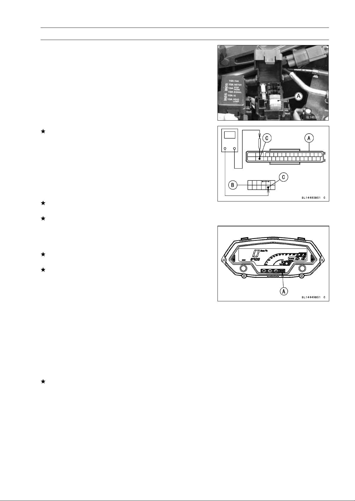
BRAKES 12-47
Anti-Lock Brake System (Equipped Models)
ABS Solenoid Valve Relay Inspection (Service
Code 19)
•
Remove:
Front Seat (see Front Seat Removal in the Frame chap-
ter)
•
Check the ABS solenoid valve relay fuse (20 A) [A] (see
Fuse Inspection in the Electrical System chapter).
If the fuse is good, check the wiring continuity that relates
to the LG lead in the main harness referring to the ABS
System Wiring Diagram.
Special Tool - Hand Tester: 57001-1394
Wiring Continuity Inspection
ABS Hydraulic Unit
Connector [A]
Fuse Box Terminal [B]
LG Lead [C]
If there is not the continuity in the lead, replace or repair
the main harness.
If ther
e is the continuity in the lead, go to next stemp.
•
Recheck the service code indication; era
se the service
code, perform the pre-diagnosis inspection 1 and 2, and
retrieve the service code.
If the ABS indicator light (LED) [A] lights, the ABS
hy-
draulic unit has trouble. Replace the ABS hydraulic unit.
If the ABS indicator light (LED) does not light, ABS system
is normal (service code is not stored; temporary failure.).
Front, Rear Wheel Rotation Difference Abnormal
(Service Code 25)
○
Check the following and correct the faulty part.
Incorrect Tire Pressure
Tires not recommended for the motorcycle were installed
(incorrect tire size).
Deformation of Wheel or Tire
Missing Teeth and Clogging with Foreign Matter of Sen-
sor Rotor (see Wheel Rotation Sensor Inspection)
If the all parts correct, recheck the service code indica-
tion; erase the service code, perform the pre-diagnosis
inspection 1 and 2, and retrieve the service code.
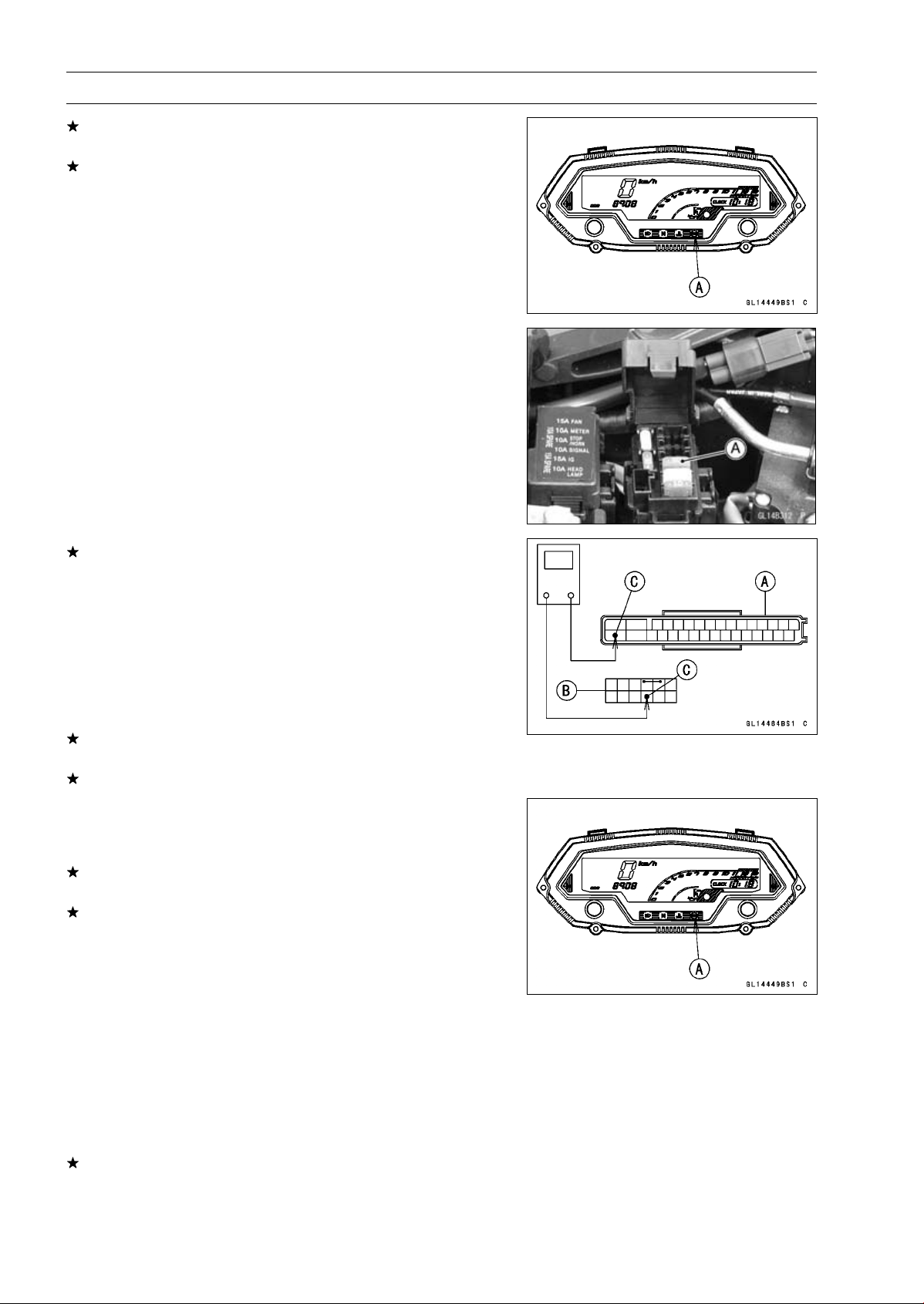
12-48 BRAKES
Anti-Lock Brake System (Equipped Models)
If the ABS indicator light (LED) [A] lights, the ABS hy-
draulic unit has trouble. Replace the ABS hydraulic unit.
If the ABS indicator light (LED) does not light, ABS system
is normal (service code is not stored; temporary failure.).
ABS Motor Relay Inspection (Service Code 35)
•
Remove:
Front Seat (see Front Seat Removal in the Frame chap-
ter)
•
Check the ABS motor relay fuse (30 A) [A] (see Fuse
Inspection in the Electrical System chapter).
If the fuse is good, check the wiring continuity that relates
to the R lead in the main harness referring to the ABS
System Wiring Diagram.
Special Tool - Hand Tester 57001-1394
Wiring Continuity Inspection
ABS Hydraulic Unit
Connector [A]
Fuse Box Terminal [B]
R Lead [C]
If there is not the continuity in the lead, replace or repair
the main harness.
If there is the continuity in the lead, go to next step.
•
Recheck the service code indication; erase the service
code, perform the pre-diagnosis inspection 1 and 2, and
retrieve the service code.
If the ABS indicator light (LED) [A] lights, the ABS hy-
draulic unit has trouble. Replace the ABS hydraulic unit.
If the ABS indicator light (LED) does not light, ABS system
is normal (service code is not stored; temporary failure.).
Front Wheel Rotation Sensor Signal Abnormal
(Service Code 42)
•
Measure the air gap between the front wheel rotation sen-
sor and sensor rotor (see Wheel Rotation Sensor Air Gap
Inspection).
•
Check the front wheel rotation sensor (see Wheel Rota-
tion Sensor Inspection).
If both inspections are good, go to next step.
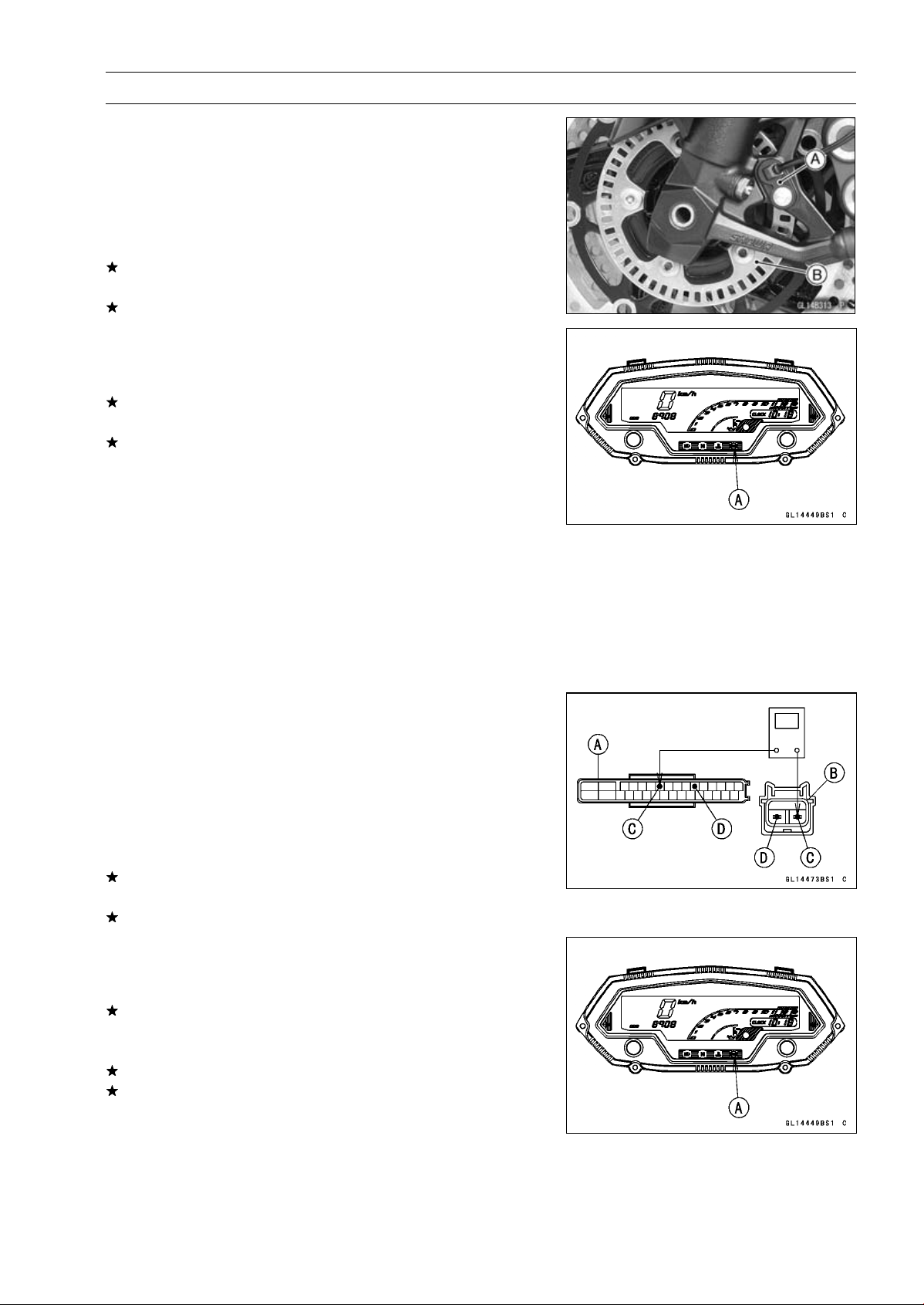
BRAKES 12-49
Anti-Lock Brake System (Equipped Models)
•
Check that there is iron or other magnetic deposits be-
tween the sensor [A] and sensor rotor [B], and the sensor
rotor slots for obstructions.
•
Check the installation condition of the sensor for loose-
ness.
•
Check the sensor rotor tip for deformation or damage
(e.g., chipped sensor rotor teeth).
If the sensor rotor in bad condition, remove the any de-
posits. Install the proper part or replace faulty part.
If the all items are good, go to next step.
•
Recheck the service code indication; erase the service
code, perform the pre-diagnosis inspection 1 and 2, and
retrieve the service code.
If the ABS indicator light (LED) [A] lights, the ABS hy-
draulic unit has trouble. Replace the ABS hydraulic unit.
If the ABS indicator light (LED) does not light, ABS system
is normal (service code is not stored; temporary failure.).
Front Wheel Rotation Sensor Wiring Inspection
(Service Code 43)
•
Disconnect:
ABS Hydraulic Unit Connector (see ABS Hydraulic Unit
Removal)
Front Wheel Rotation Sensor Connector (see Front
Wheel Rotation Sensor Removal)
•
Check the wiring continuity of the G lead and BK/R lead.
Special Tool - Hand Tester 57001-1394
Wiring Continuity Inspection
ABS Hydraulic Unit
Connector [A]
Front Wheel Rotation
Sensor Connector [B]
BK/R Lead Terminal [C]
G Lead Terminal [D]
If there is not the continuity in the lead, replace or repair
the main harness.
If the wiring is good, go to next step.
•
Recheck the service code indication; erase the service
code, perform the pre-diagnosis inspection 1 and 2, and
retrieve the service code.
If the ABS indicator light (LED) [A] lights, replace the front
wheel rotation sensor (see Front Wheel Rotation Sensor
Removal).
Still, when it is not good, replace the ABS hydraulic unit.
If the ABS indicator light (LED) does not light, ABS system
is normal (service code is not stored; temporary failure.).
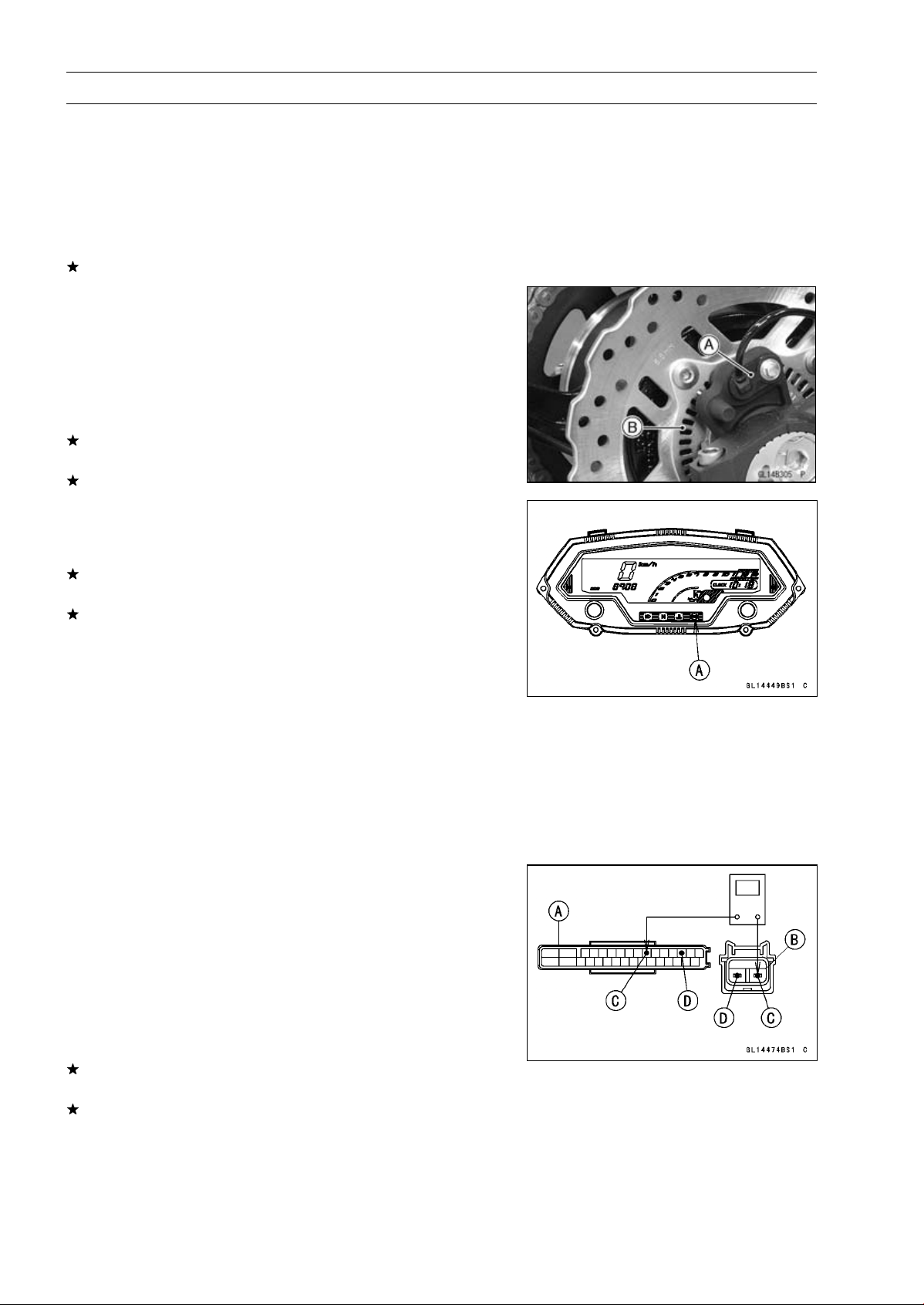
12-50 BRAKES
Anti-Lock Brake System (Equipped Models)
Rear Wheel Rotation Sensor Signal Abnormal
(Service Code 44)
•
Measure the air gap between the rear wheel rotation sen-
sor and sensor rotor (see Wheel Rotation Sensor Air Gap
Inspection).
•
Check the rear wheel rotation sensor (see Rear Wheel
Rotation Sensor Inspection).
If both inspections are good, go to next step.
•
Check that there is iron or other magnetic deposits be-
tween the sensor [A] and sensor rotor [B], and the sensor
rotor slots for obstructions.
•
Check the installation condition of the sensor for loose-
ness.
•
Check the sensor rotor tip for deformation or damage
(e.g., chipped sensor rotor teeth).
If the sensor rotor in bad condition, remove the any de-
posits. Install the proper part or replace faulty part.
If the all items are good, go to next step.
•
Recheck the service code indication; erase the service
code, perform the pre-diagnosis inspection 1 and 2, and
retrieve the service code.
If the ABS indicator light (LED) [A] lights, the ABS hy-
draulic unit has trouble. Replace the ABS hydraulic unit.
If the ABS indicator light (LED) does not light, ABS system
is normal (service code is not stored; temporary failure.).
Rear Wheel Rotation Sensor Wiring Inspection
(Service Code 45)
•
Disconnect:
ABS Hydraulic Unit Connector (see ABS Hydraulic Unit
Removal)
Rear Wheel Rotation Sensor Connector (see Rear
Wheel Rotation Sensor Removal)
•
Check the wiring continuity of the BK lead and BR/BK
lead.
Special Tool - Hand Tester 57001-1394
Wiring Continuity Inspection
ABS Hydraulic Unit
Connector [A]
Rear Wheel Rotation
Sensor Connector [B]
BK Lead Terminal [C]
BR/BK Lead Terminal [D]
If there is not the continuity in the lead, replace or repair
the main harness.
If the wiring is good, go to next step.
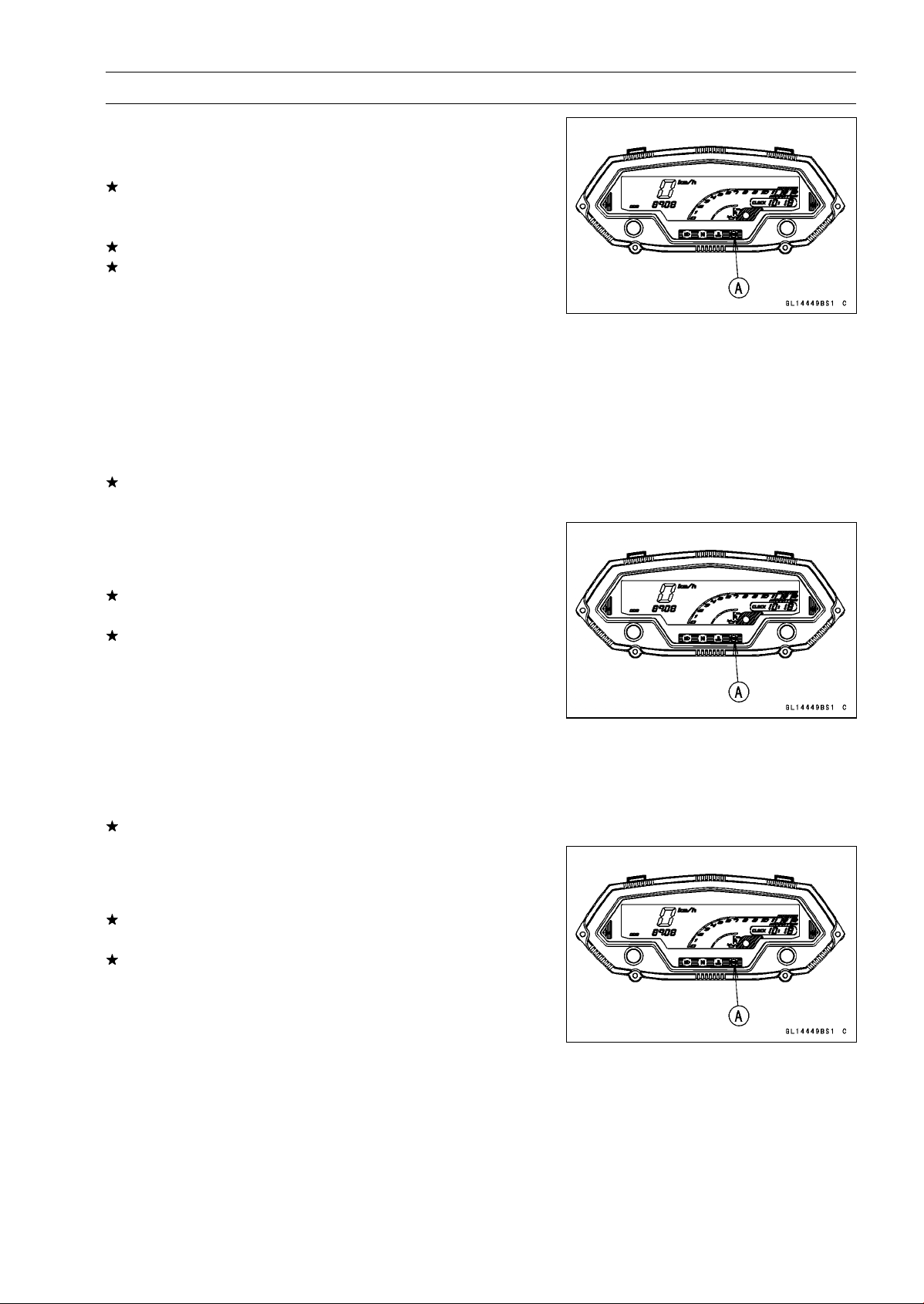
BRAKES 12-51
Anti-Lock Brake System (Equipped Models)
•
Recheck the service code indication; erase the service
code, perform the pre-diagnosis inspection 1 and 2, and
retrieve the service code.
If the ABS indicator light (LED) [A] lights, replace the rear
wheel rotation sensor (see Rear Wheel Rotation Sensor
Removal).
Still, when it is not good, replace the ABS hydraulic unit.
If the ABS indicator light (LED) does not light, ABS system
is normal (service code is not stored; temporary failure.).
Power Supply Voltage Abnormal (Low-Voltage)
(Service Code 52)
•
Check:
Battery Condition (see Charging Condition Inspection in
the Electrical System chapter)
Charging Voltage (see Charging Voltage Inspection in
the Electrical System chapter)
If the battery and charging voltage are good condition, go
to next step.
•
Recheck the service code indication; erase the service
code, perform the pre-diagnosis inspection 1 and 2, and
retrieve the service code.
If the ABS indicator light (LED) [A] lights, the ABS hy-
draulic unit has trouble. Replace the ABS hydraulic unit.
If the ABS indicator light (LED) does not light, ABS system
is normal (service code is not stored; temporary failure.).
Power Supply Voltage Abnormal (Over-Voltage)
(Service Code 53)
•
Check the charging voltage (see Charging Voltage In-
spection in the Electrical System chapter).
If the charging voltage is good, go to next step.
•
Recheck the service code indication; erase the service
code, perform the pre-diagnosis inspection 1 and 2, and
retrieve the service code.
If the ABS indicator light (LED) [A] lights, the ABS hy-
draulic unit has trouble. Replace the ABS hydraulic unit.
If the ABS indicator light (LED) does not light, ABS system
is normal (service code is not stored; temporary failure.).
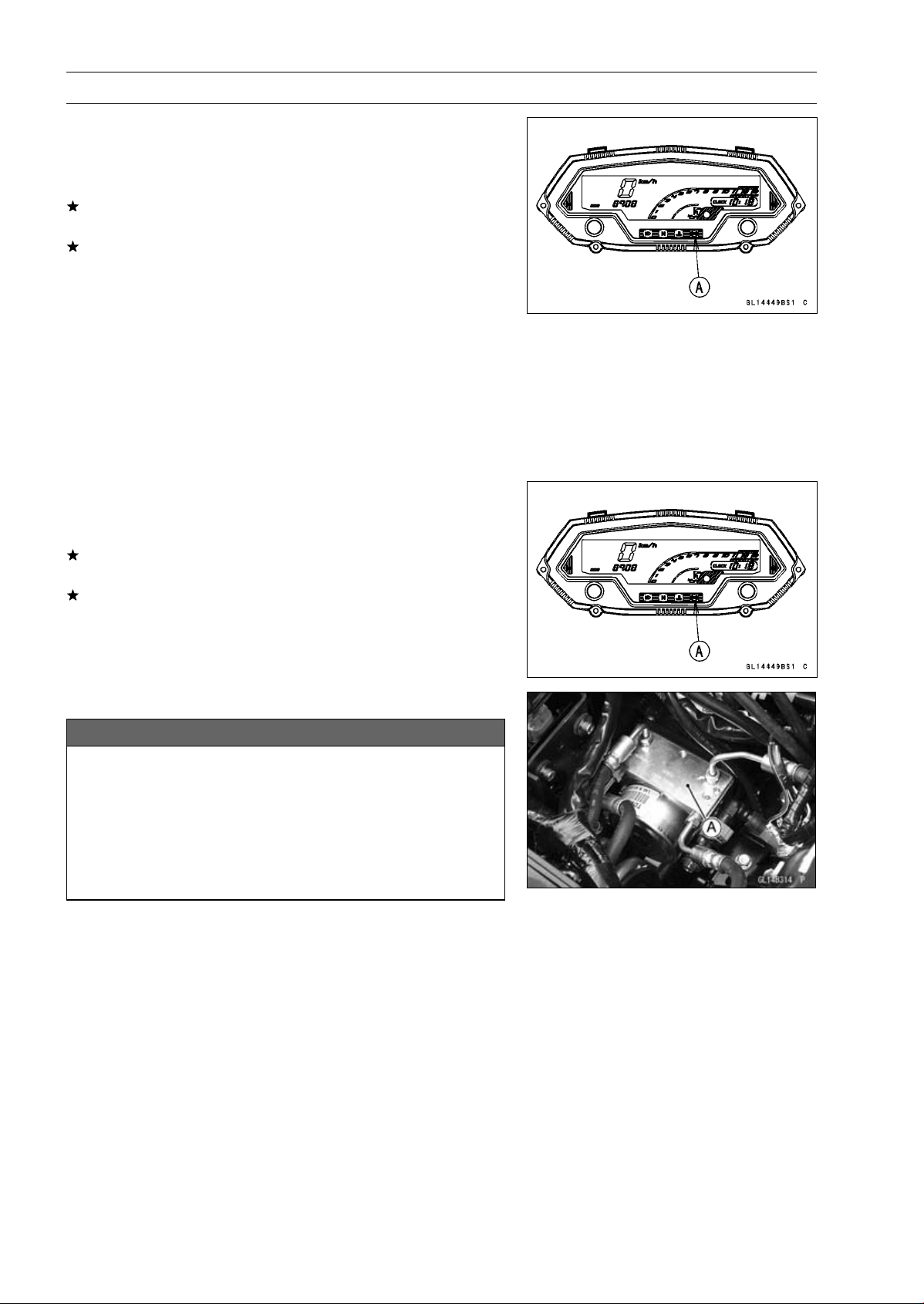
12-52 BRAKES
Anti-Lock Brake System (Equipped Models)
ECU Inspection (Service Code 55)
•
Recheck the service code indication; erase the service
code, perform the pre-diagnosis inspection 1 and 2, and
retrieve the service code.
If the ABS indicator light (LED) [A] lights, the ABS hy-
draulic unit has trouble. Replace the ABS hydraulic unit.
If the ABS indicator light (LED) does not lgiht, ABS system
is normal (service code is not stored; temporary failure.).
Wheel Rotation Sensor Signal Abnormal [Too
High Speed] (Service Code 93)
○
When the wheel rotation sensor signal detects 340 km/h
or more at a motor cycle speed of 264 km/h or more, this
service code is detected. Therefore, this service code
might be detected by a special operation condition or us-
ing the substandard tire.
•
Recheck the service code indication; erase the service
code, perform the pre-diagnosis inspection 1 and 2, and
retrieve the service code.
If the ABS indicator light (LED) [A] lights, the ABS hy-
draulic unit has trouble. Replace the ABS hydraulic unit.
If the ABS indicator light (LED) does not light, ABS system
is normal (service code is not stored; temporary failure.).
ABS Hydraulic Unit Removal
NOTICE
The ABS hydraulic unit [A] has been adjusted
and set with precision at the factory. Therefore, it
should be handled carefully, never struck sharply,
as with a hammer, or allowed to fall on a hard
surface.
Be careful not to get water or mud on the ABS hy-
draulic unit.
•
Drain the brake fluid from the front and rear brake lines.
○
Drain the brake fluid through the bleed valve by pumping
the brake lever and pedal.
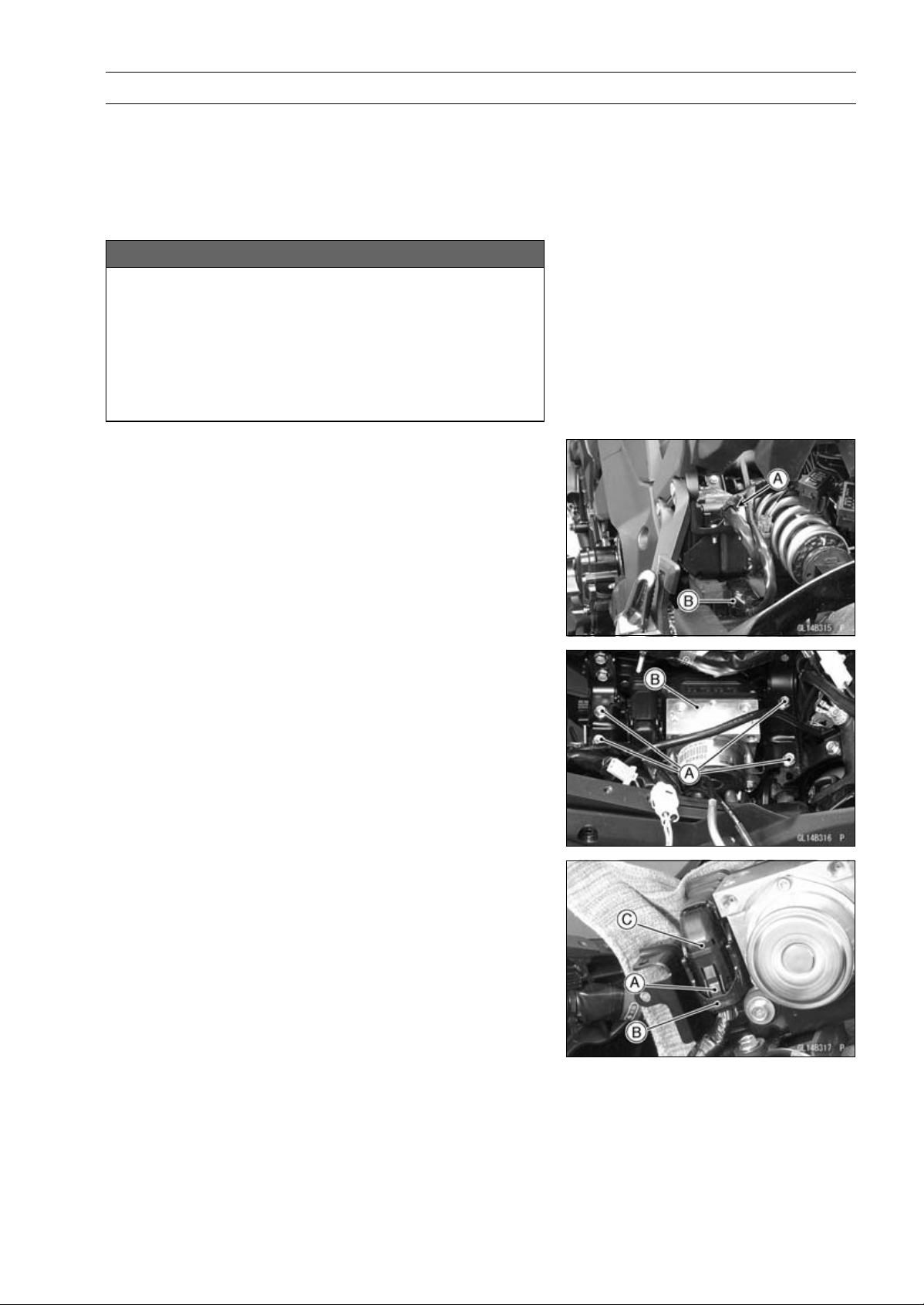
BRAKES 12-53
Anti-Lock Brake System (Equipped Models)
•
Remove:
Battery Case (see Battery Case Removal in the Frame
chapter)
Brake Hose (see Brake Hose Replacement in the Peri-
odic maintenance chapter)
•
Clean the ABS hydraulic unit.
NOTICE
Clean all fittings on the ABS hydraulic unit and the
rear master cylinder because dirt around the banjo
bolts could contaminate the brake fluid in the line
during removal/installation.
Spread over a shop towel around the ABS hydraulic
unit before removing the brake line so that brake
fluid does not leak on the parts.
•
Open the clamp [A].
•
Disconnect the regulator/rectifier connector [B].
•
Remove the bolts [A].
•
Pull up the ABS hydraulic unit [B].
•
While pushing the stopper [A], unlock the connector lock
[B] upward.
•
Disconnect the connector [C].
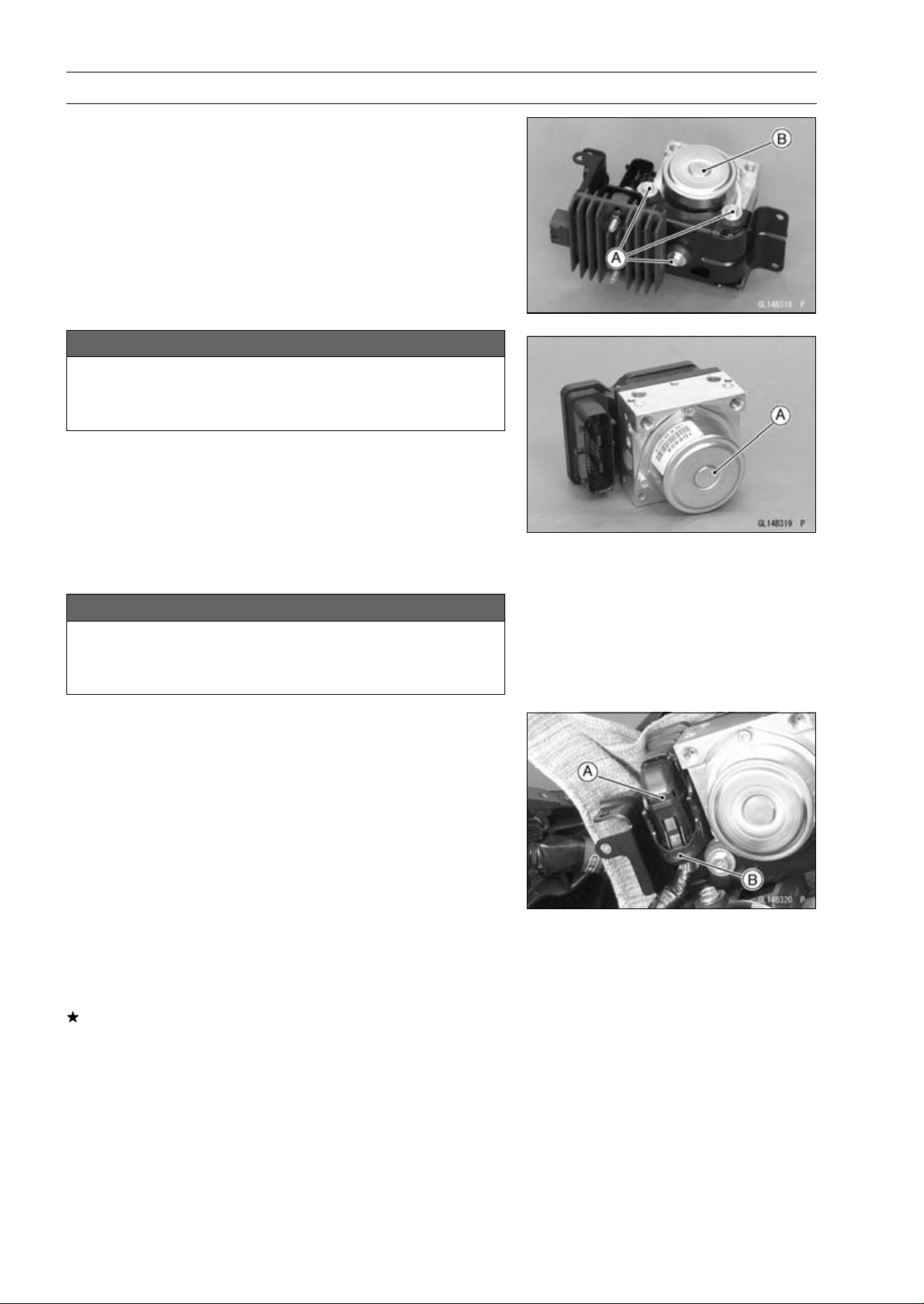
12-54 BRAKES
Anti-Lock Brake System (Equipped Models)
•
Remove:
Bolts [A]
ABS Hydraulic Unit [B]
NOTICE
The ABS hydraulic unit [A] has been adjusted and
set with precision at the factory. Do not try to dis-
assemble and repair the ABS hydraulic unit.
ABS Hydraulic Unit Installation
•
Install the ABS hydraulic unit to the bracket.
NOTICE
Brake fluid quickly ruins painted plastic surfaces;
any spilled fluid should be completely washed away
immediately.
•
Run the lead correctly, and connect the connector [A] se-
curely.
○
Lock the connector lock [B] as shown in the figure.
•
Install the brake hoses correctly (see Brake Hose Re-
placement in the Periodic Maintenance chapter).
•
Bleed the brake line (see Brake Line Bleeding).
•
Check the brake for good braking power, no brake drag,
and no fluid leakage.
•
Install the removed parts (see appropriate chapters).
ABS Hydraulic Unit Inspection
•
Remove the ABS hydraulic unit (see ABS Hydraulic Unit
Removal).
•
Visually inspect the ABS hydraulic unit.
Replace the ABS hydraulic unit if any of them are cracked,
or otherwise damaged.
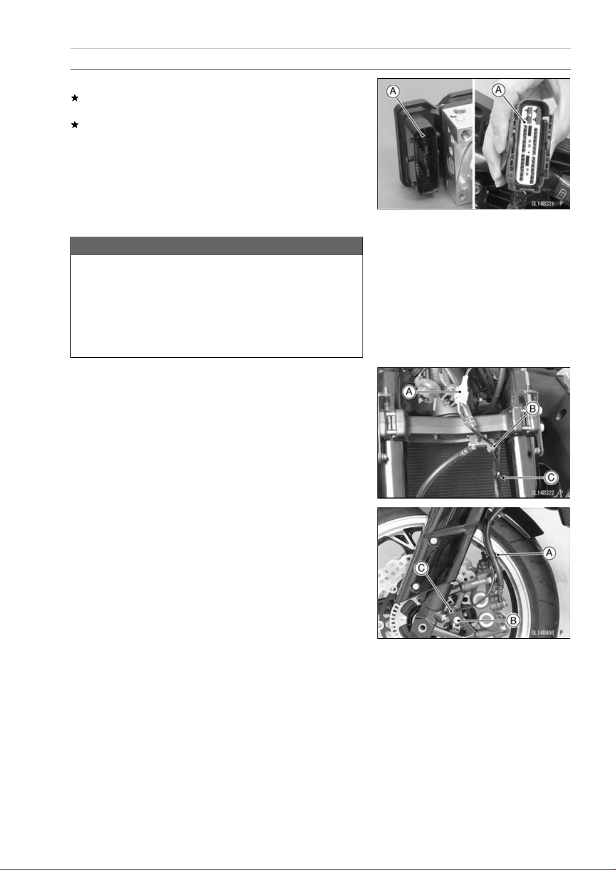
BRAKES 12-55
Anti-Lock Brake System (Equipped Models)
•
Visually inspect the connector terminals [A].
Replace the ABS hydraulic unit or main harness if either
of the terminals are cracked, bent, or otherwise damaged.
If the ABS hydraulic unit connector is clogged with mud
or dust, blow it off with compressed air.
Front Wheel Rotation Sensor Removal
NOTICE
The wheel rotation sensor should be handled care-
fully, never struck sharply, as with a hammer, or al-
lowed to fall on a hard surface since the wheel rota-
tion sensor is precision made. Be careful not to get
water or mud on the wheel rotation sensor.
Do not try to disassemble or repair the wheel rota-
tion sensor.
•
Remove:
Upper Fairing (see Upper Fairing Removal in the Frame
chapter)
Connector [A] (Disconnect)
Grommet [B]
Clamp [C]
•
Clear the sensor lead from the clamp [A].
•
Remove:
Bolt [B]
Front Wheel Rotation Sensor [C]
Front Wheel Rotation Sensor Installation
•
Installation is the reverse of removal.
○
Run the lead correctly (see Cable, Wire, and Hose Rout-
ing section in the Appendix chapter).
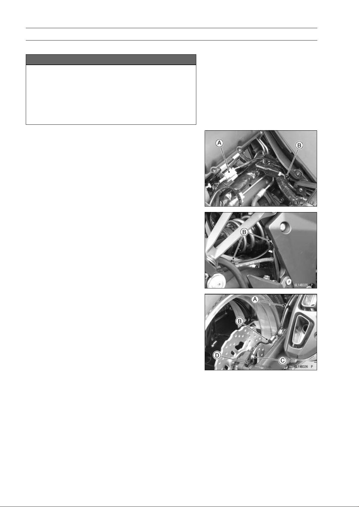
12-56 BRAKES
Anti-Lock Brake System (Equipped Models)
Rear Wheel Rotation Sensor Removal
NOTICE
The wheel rotation sensor should be handled care-
fully, never struck sharply, as with a hammer, or al-
lowed to fall on a hard surface since the wheel rota-
tion sensor is precision made. Be careful not to get
water or mud on the wheel rotation sensor.
Do not try to disassemble or repair the wheel rota-
tion sensor.
•
Remove:
Fuel Tank (see Fuel Tank Removal in the Fuel System
(DFI) chapter)
Connector [A] (Disconnect)
•
Clear the sensor lead from the clamps [B].
•
Clear the sensor lead from the clamp [A].
•
Remove:
Grommet [B]
Bolt [C]
Rear Wheel Rotation Sensor [D]
Rear Wheel Rotation Sensor Installation
•
Installation is the reverse of removal.
○
Route the lead correctly (see Cable, Wire, and Hose
Routing section in the Appendix chapter).
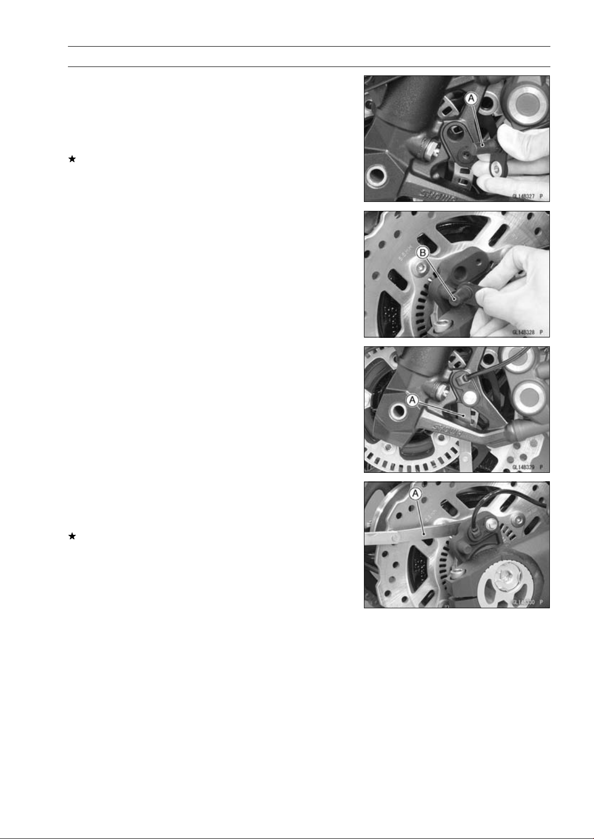
BRAKES 12-57
Anti-Lock Brake System (Equipped Models)
Wheel Rotation Sensor Inspection
•
Remove the front wheel rotation sensor [A] from the front
fork.
•
Remove the rear wheel rotation sensor [B] from the
caliper bracket.
•
Visually inspect the wheel rotation sensors.
Replace the wheel rotation sensor if it is cracked, bent, or
otherwise damaged.
Wheel Rotation Sensor Air Gap Inspection
•
Raise the front/rear wheel off the ground (see Front/Rear
Wheel Removal in the Wheels/Tires chapter).
•
Measure the air gap between the sensor and sensor rotor
at several points by turning the wheel slowly.
Thickness Gauge [A]
Air Gap
Standard:
Front
1.98
∼ 2.86 mm (0.0780 ∼ 0.113 in.)
Rear
1.12
∼ 1.85 mm (0.0441 ∼ 0.0728 in.)
NOTE
○
The sensor air gap cannot be adjusted.
If the air gap is not within the specification, inspect the hub
bearing (see Hub Bearing Inspection in the Wheels/Tires
chapter), sensor installation condition and sensor (see
Wheel Rotation Sensor Inspection).
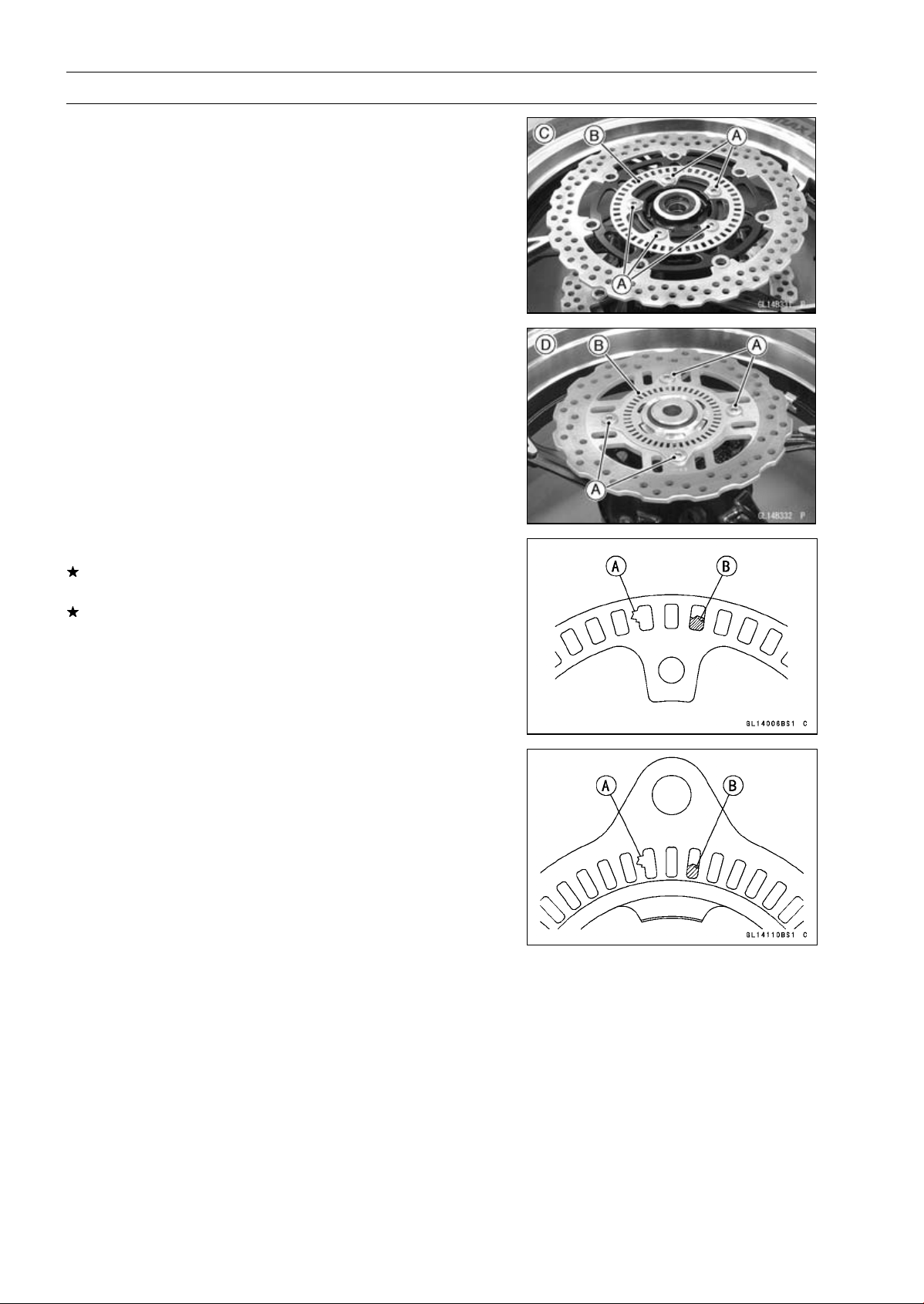
12-58 BRAKES
Anti-Lock Brake System (Equipped Models)
Wheel Rotation Sensor Rotor Inspection
•
Remove:
Wheels (see Front/Rear Wheel Removal in the
Wheels/Tires chapter)
Brake Disc Mounting Bolts [A]
Sensor Rotor [B]
Front Wheel [C]
Rear Wheel [D]
•
Visually inspect the wheel rotation sensor rotor.
If the rotor is deformed or damaged (chipped teeth [A]),
replace the sensor rotor with a new one.
If there is iron or other magnetic deposits [B], remove the
deposits.
ABS Solenoid Valve Relay Fuse (20 A) Removal
•
Refer to the Fuse Box Fuse Removal in the Electrical Sys-
tem chapter.
ABS Motor Relay Fuse (30 A) Removal
•
Refer to the Fuse Box Fuse Removal in the Electrical Sys-
tem chapter.
ABS ECU Fuse (10 A) Removal
•
Refer to the Fuse Box Fuse Removal in the Electrical Sys-
tem chapter.

BRAKES 12-59
Anti-Lock Brake System (Equipped Models)
Fuse Installation
•
If a fuse fails during operation, inspect the electrical sys-
tem to determine the cause, and then replace it with a
new fuse of proper amperage (see Fuse Installation in the
Electrical System chapter).
Fuse Inspection
•
Remove the fuses (see ABS Solenoid Valve Relay Fuse
(20 A)/ABS Motor Relay Fuse (30 A)/ABS ECU Fuse (10
A) Removal).
•
Refer to the Fuse Inspection in the Electrical System
chapter.


SUSPENSION 13-1
13
Suspension
Table of Contents
Exploded View........................................................................................................................ 13-2
Specifications ......................................................................................................................... 13-6
Special Tools .......................................................................................................................... 13-7
Front Fork............................................................................................................................... 13-9
Rebound Damping Force Adjustment .............................................................................. 13-9
Spring Preload Adjustment ............................................................................................... 13-9
Compression Damping Force Adjustment ........................................................................ 13-10
Front Fork Removal (Each Fork Leg) ............................................................................... 13-10
Front Fork Installation ....................................................................................................... 13-11
Fork Oil Change................................................................................................................ 13-11
Front Fork Disassembly .................................................................................................... 13-17
Front Fork Assembly......................................................................................................... 13-18
Inner Tube, Outer Tube Inspection ................................................................................... 13-19
Dust Seal Inspection ......................................................................................................... 13-19
Spring Tension Inspection................................................................................................. 13-19
Rear Shock Absorber ............................................................................................................. 13-20
Rebound Damping Force Adjustment............................................................................... 13-20
Spring Preload Adjustment ............................................................................................... 13-20
Rear Shock Absorber Removal ........................................................................................ 13-21
Rear Shock Absorber Installation ..................................................................................... 13-22
Rear Shock Absorber Inspection ...................................................................................... 13-22
Rear Shock Absorber Scrapping ...................................................................................... 13-22
Rear Shock Absorber Bearing Removal........................................................................... 13-23
Rear Shock Absorber Bearing Installation........................................................................ 13-23
Swingarm................................................................................................................................ 13-24
Swingarm Removal........................................................................................................... 13-24
Swingarm Installation........................................................................................................ 13-25
Swingarm Bearing Removal ............................................................................................. 13-26
Swingarm Bearing Installation .......................................................................................... 13-26
Swingarm Bearing, Sleeve Inspection .............................................................................. 13-27
Swingarm Bearing Lubrication .......................................................................................... 13-27
Chain Guide Inspection..................................................................................................... 13-27
Tie-Rod, Rocker Arm.............................................................................................................. 13-28
Tie-Rod Removal .............................................................................................................. 13-28
Tie-Rod Installation ........................................................................................................... 13-28
Rocker Arm Removal........................................................................................................ 13-28
Rocker Arm Installation..................................................................................................... 13-28
Tie-Rod and Rocker Arm Bearing Removal...................................................................... 13-29
Tie-Rod and Rocker Arm Bearing Installation................................................................... 13-29
Rocker Arm/Tie-Rod Bearing, Sleeve Inspection ............................................................. 13-30
Rocker Arm/Tie-Rod Bearing Lubrication ......................................................................... 13-30
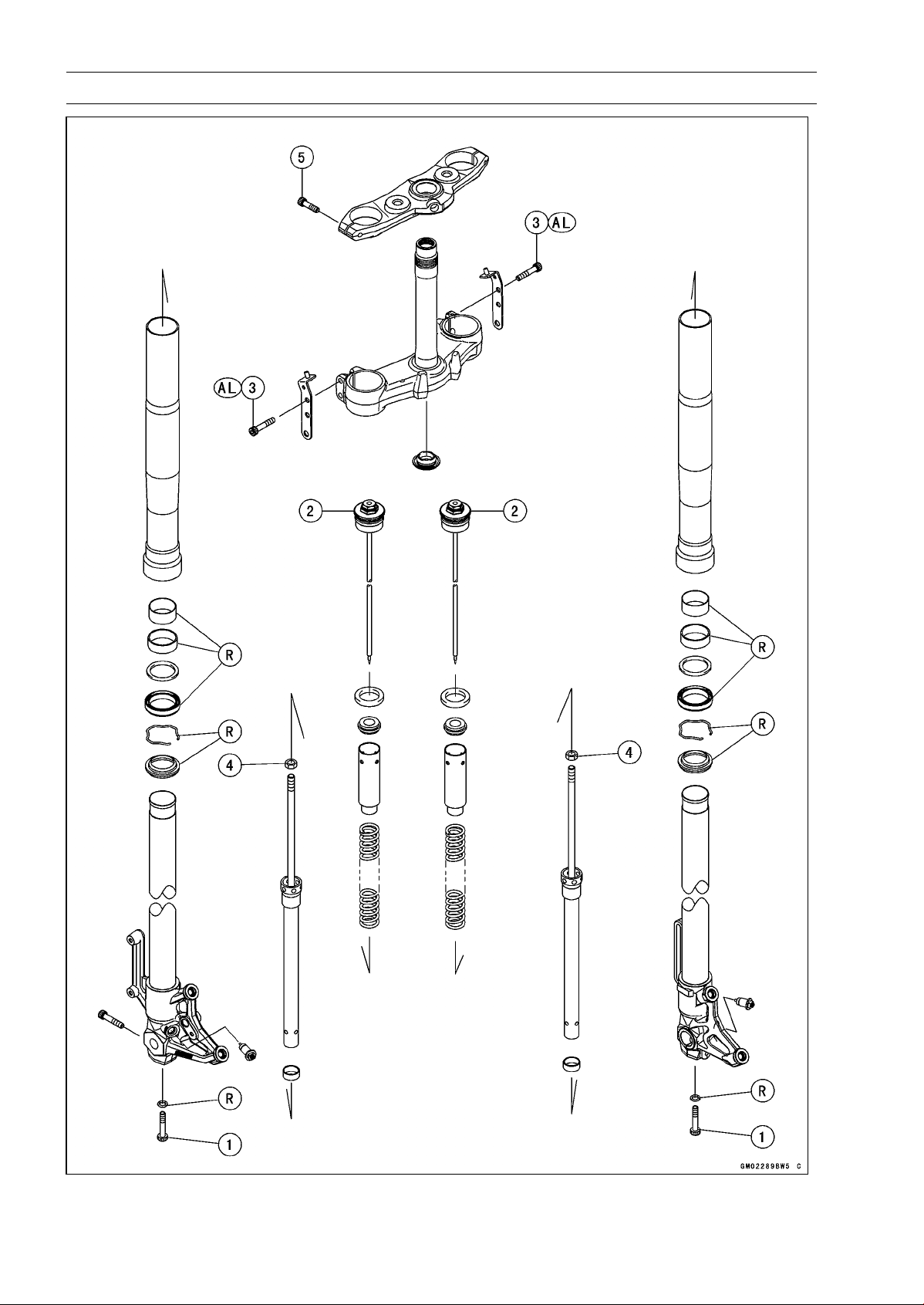
13-2 SUSPENSION
Exploded View

SUSPENSION 13-3
Exploded View
Torque
No. Fastener
N·m
kgf·m ft·lb
Remarks
1 Front Fork Bottom Allen Bolts 35 3.6 26
2 Front Fork Top Plugs 34 3.5 25
3 Lower Front Fork Clamp Bolts 25 2.5 18 AL
4 Piston Rod Nuts 20 2.0 15
5 Upper Front Fork Clamp Bolts 20 2.0 15
AL: Tighten the two clamp bolts alternately two times to ensure even tightening torque.
R: Replacement Parts
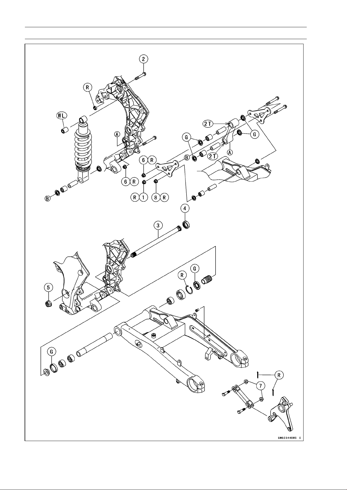
13-4 SUSPENSION
Exploded View

SUSPENSION 13-5
Exploded View
Torque
No. Fastener
N·m
kgf·m ft·lb
Remarks
1
Rear Shock Absorber Nut (Lower)
34 3.5 25 R
2 Rear Shock Absorber Bolt (Upper) 34 3.5 25
3 Swingarm Pivot Shaft 20 2.0 15
4 Swingarm Pivot Adjusting Collar Locknut 98 10 72
5 Swingarm Pivot Shaft Nut 108 11.0 79.7
6 Tie-rod Nuts 34 3.5 25 R
7 Torque Link Nuts 34 3.5 25
8 Rocker Arm Nut 34 3.5 25 R
2T: Apply 2-stroke oil.
G: Apply grease.
R: Replacement Parts
WL: Apply soap and water solution or rubber lubricant.

13-6 SUSPENSION
Specifications
Item Standard
Front Fork (Per One Unit)
Fork Inner Tube Diameter 41 mm (1.6 in.)
Air Pressure Atmospheric pressure (non-adjustable)
Rebound Damper Setting
2 turns out from the fully clockwise position
(Usable range: 0 ←→ 3 1/2 turns out)
Compression Damper Setting
1 3/4 turns out from the fully clockwise position
(Usable range: 0 ←→ 3 turns out)
Fork Spring Preload Setting
5 turns in from the fully counterclockwise position
(Usable range: 0 ←→ 15 turns in)
Fork Oil:
Recommend Oil SHOWA SS-47 or equivalent
Amount:
When Changing Oil Approx. 365 mL (12.3 US oz.)
After Disassembly and
Completely Dry
432 ±2.5 mL (14.6 ±0.085 US oz.)
Fork Oil Level: (Fully
Compressed, without Spring,
below from the Top of the Outer
Tube)
100 ±2 mm (3.94 ±0.08 in.)
Fork Spring Free L
ength
268 mm (10.6 in.) (
Service Limit: 263 mm (10.4 in.))
Rear Shock Absorber
Rebound Damper Setting
ZR1000DA/EA 1 3/4 turns out from the fully clockwise position
(Usable Range: 0 ←→ 2 1/2 turns out)
ZR1000DB ∼/EB ∼ 2 turns out from the fully clockwise position
(Usable Range: 0
←→ 2 1/2 turns out)
Spring Preload Setting Position:
Standard Spring length: 184.5 mm (7.264 in.)
Usable Range Spring length: 179.5 ∼ 189.5 mm (7.067 ∼ 7.461 in.) (stronger
to weaker)
Gas Pressure 980 kPa (10 kgf/cm², 142 psi, Non-adjustable)
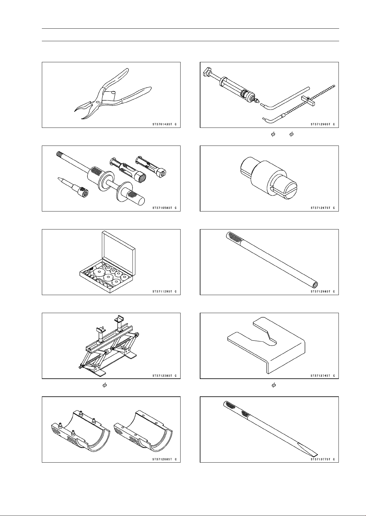
SUSPENSION 13-7
Special Tools
Inside Circlip Pliers:
57001-143
Oil Seal & Bearing Remover:
57001-1058
Bearing Driver Set:
57001-1129
Jack:
57001-1238
Fork Oil Seal Driver, 41:
57001-1288
Fork Oil Level Gauge:
57001-1290
Bearing Remover Head, 15 × 17:
57001-1267
Fork Piston Rod Puller, M10 × 1.0:
57001-1298
Fork Spring Stopper:
57001-1374
Bearing Remover Shaft, 13:
57001-1377
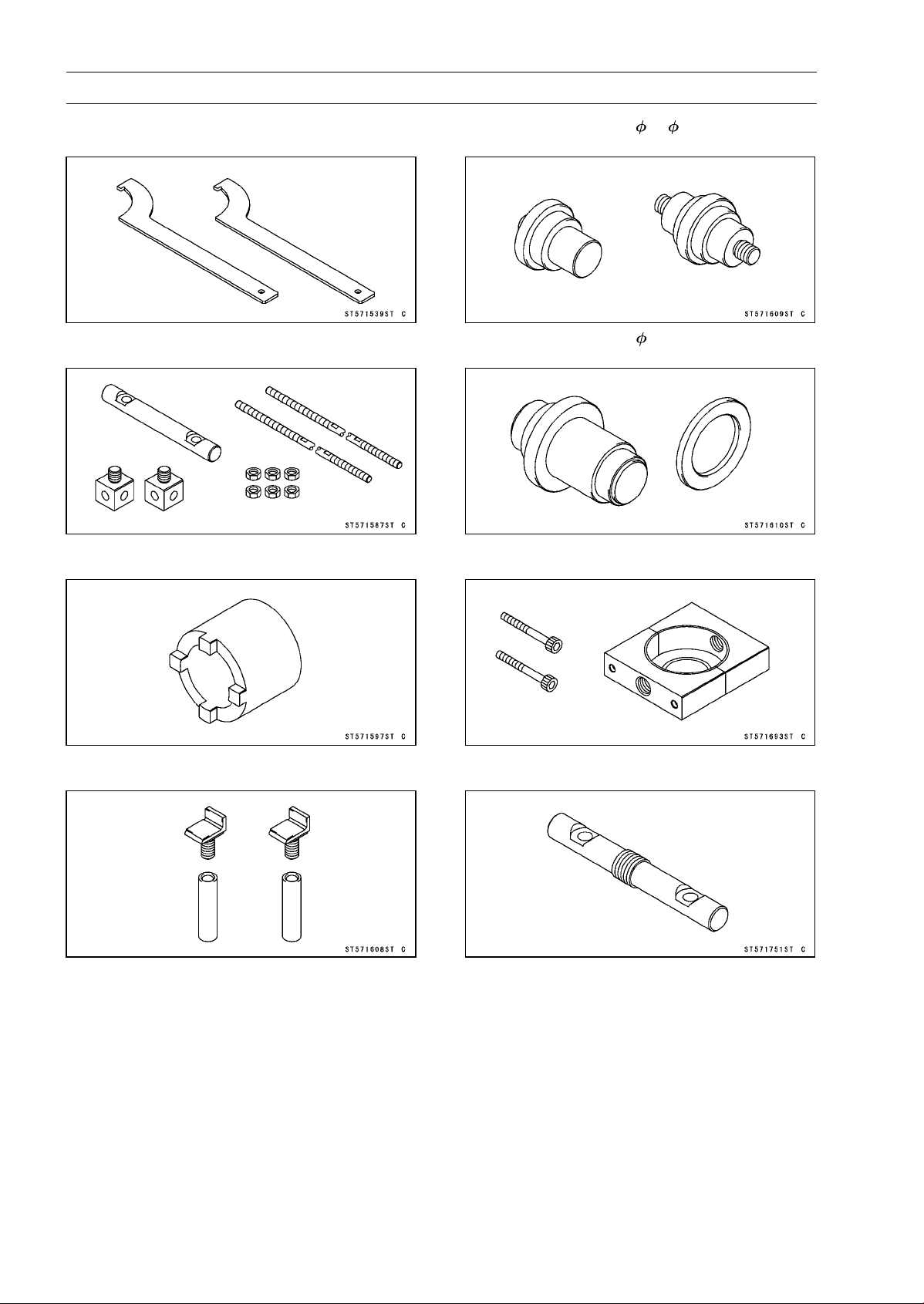
13-8 SUSPENSION
Special Tools
Hook Wrench T=3.2 R37:
57001-1539
Fork Spring Compressor:
57001-1587
Swingarm Pivot Nut Wrench:
57001-1597
Jack Attachment:
57001-1608
Needle Bearing Driver, 17/ 18:
57001-1609
Needle Bearing Driver, 28:
57001-1610
Clamp:
57001-1693
Bar:
57001-1751

SUSPENSION 13-9
Front Fork
Rebound Damping Force Adjustment
•
To adjust the rebound damping force, turn the rebound
damping adjuster [A] until you feel a click.
○
The standard adjuster setting is the 2 turns out from the
fully clockwise position.
WARNING
If both adjusters are not adjusted equally, handling
may be impaired and a hazardous condition may
result. Be sure the adjusters are set equally.
○
The damping force can be left soft for average riding. But
it should be adjusted harder for high speed riding or riding
with a passenger. If the damping feels too soft or too stiff,
adjust it in accordance with the following table.
Rebound Damping Force Adjustment
Adjuster
Position
Damping
Force
Setting
Load Road
Speed
3 1/2 turns out
Weak
Soft
Light
Good
Low
↑ ↑ ↑ ↑ ↑ ↑
↓ ↓ ↓ ↓ ↓ ↓
0 Strong Hard Heavy Bad High
Spring Preload Adjustment
•
Turn the spring preload adjuster [A] to change spring
preload setting.
○
The standard adjuster setting is the 5 turns in from the
fully counterclockwise position.
WARNING
If both adjusters are not adjusted equally, handling
may be impaired and a hazardous condition may
result. Be sure the adjusters are set equally.
○
The spring preload can be left soft for average riding. But
it should be adjusted harder for high speed riding or riding
with a passenger. If the spring action feels too soft or too
stiff, adjust it in accordance with the following table.
Spring Action
Adjuster
Position
Damping
Force
Setting
Load Road
Speed
0
Weak
Soft
Light
Good
Low
↑ ↑ ↑ ↑ ↑ ↑
↓ ↓ ↓ ↓ ↓ ↓
15 turns in
Strong Hard Heavy Bad High
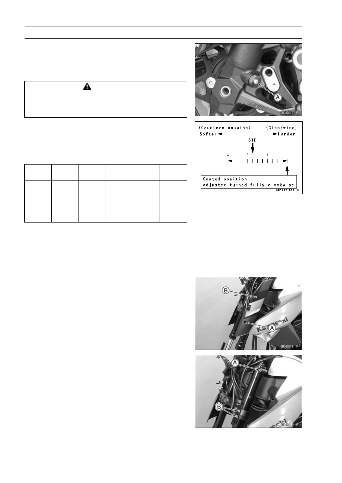
13-10 SUSPENSION
Front Fork
Compression Damping Force Adjustment
•
To adjust the compression damping force, turn the com-
pression damping adjuster [A] until you feel a click.
○
The standard adjuster setting is the 13/4turnsoutfrom
the fully clockwise position.
WARNING
If both adjusters are not adjusted equally, handling
may be impaired and a hazardous condition may
result. Be sure the adjusters are set equally.
○
The damping force can be left soft for average riding. But
it should be adjusted harder for high speed riding or riding
with a passenger. If the damping feels too soft or too stiff,
adjust it in accordance with the following table.
Compression Damping Force Adjustment
Adjuster
Position
Damping
Force
Setting
Load Road
Speed
3 Turns
out
Weak
Soft
Light
Good
Low
↑ ↑ ↑ ↑ ↑ ↑
↓ ↓ ↓ ↓ ↓ ↓
0
Strong
Hard Heavy Bad High
Front Fork Removal (Each Fork Leg)
•
Remove:
Upper Fairing (see Upper Fairing Removal in the Frame
chapter)
Front Wheel (see Front Wheel Removal in the
Wheels/Tires chapter)
•
Remove:
Bolt [A]
Front Fork Cover [B]
•
Loosen the upper front fork clamp bolt [A] and lower front
clamp bolts [B].
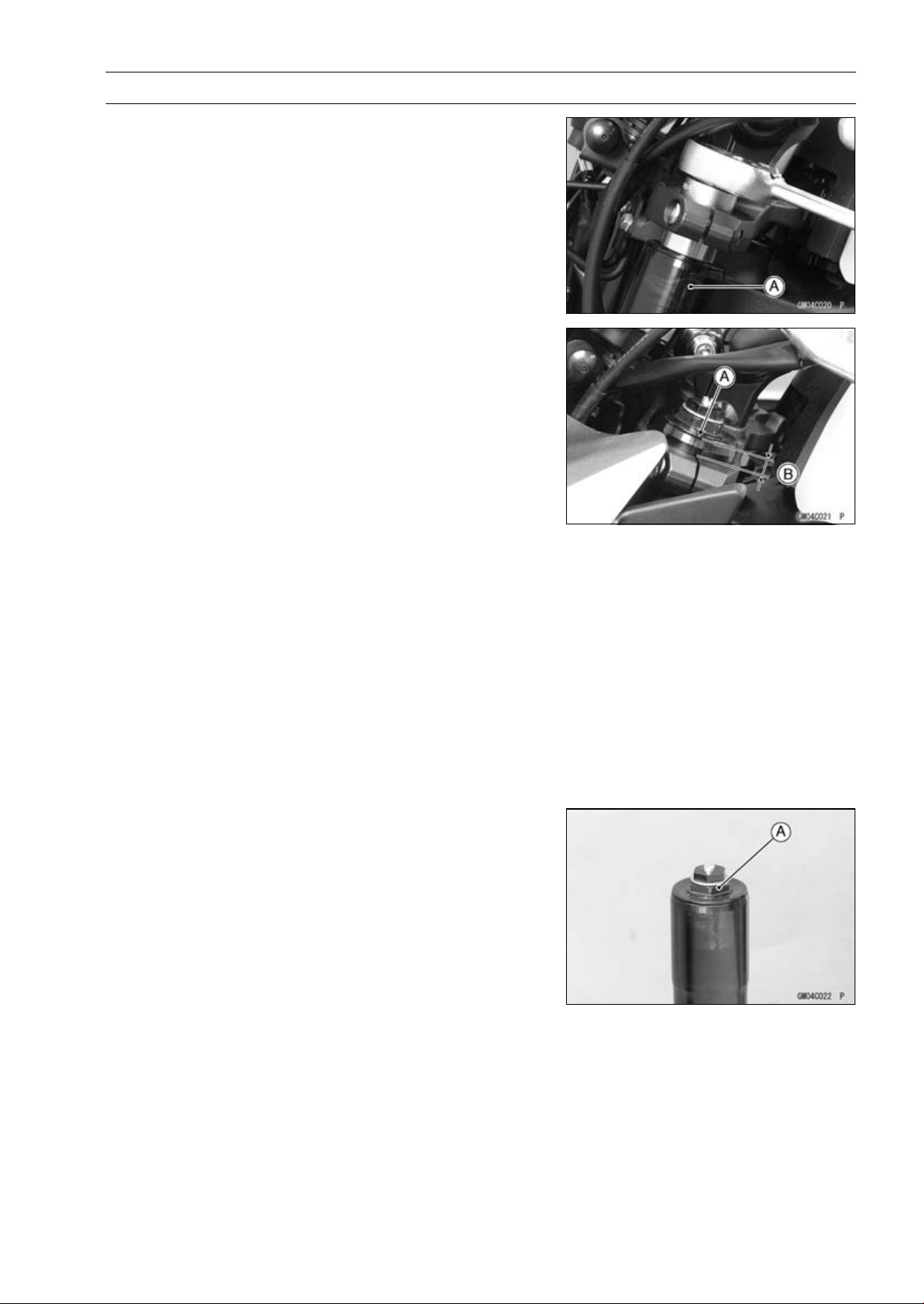
SUSPENSION 13-11
Front Fork
○
If fork leg is to be disassembled, loosen the upper and
lower front fork clamp bolts to lower the fork leg [A] as
shown. And retighten the lower front fork clamp bolts.
Then, loosen the top plug beforhand.
NOTE
○
Loosen the top plug after loosening the upper front fork
clamp bolt.
○
Loosen the lower front fork clamp bolts.
•
With a twisting motion, work the fork leg down and out.
Front Fork Installation
•
Install the fork so that the top end [A] of the outer tube as
shown in the figure.
9 mm (0.35 in.) [B]
•
Tighten:
Torque - Lower Front Fork Clamp Bolts : 25 N·m (2.5 kgf·m,
18 ft·lb)
Front Fork Top Plugs: 34 N·m (3.5 kgf·m, 25 ft·lb)
Upper Front Fork Clamp Bolts: 20 N·m (2.0 kgf·m,
15 ft·lb)
NOTE
○
Tighten the top plug before tightening the upper front
fork clamp bolt.
○
Tighten the two clamp bolts (lower) alternately two times
to ensure even tightening torque.
•
Install the removed parts (see appropriate chapters).
•
Adjust:
Spring Preload (see Spring Preload Adjustment)
Rebound Damping Force (see Rebound Damping Force
Adjustment)
Compression Damping Force (see Compression Damp-
ing Force Adjustment)
Fork Oil Change
•
Remove the front fork (see Front Fork Removal).
•
Hold the inner tube lower end in a vice.
•
Unscrew the top plug [A] out of the outer tube.
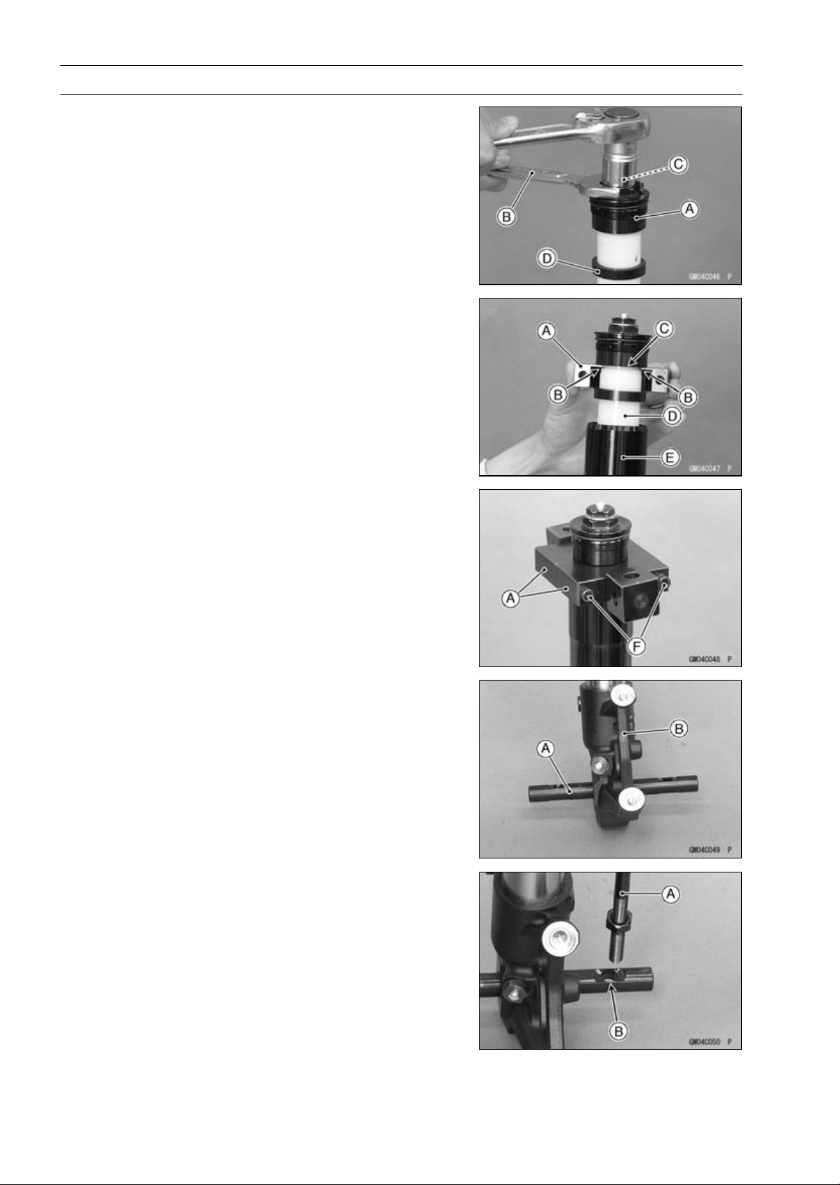
13-12 SUSPENSION
Front Fork
•
Holding the top plug [A] with a wrench [B], tighten the
spring preload adjuster [C].
NOTE
○
After tightening, lift the top plug to make the space.
•
Side down the damper [D].
•
Install the clamps [A] as shown in the figure.
NOTE
○
Set the cutout [B] of the clamp to the groove [C] of collar
[D], pull up the outer tube [E] to hold it by the clamps,
and then tighten the two bolts [F]. The outer tube is used
as a guide.
Special Tools - Fork Spring Compressor: 57001-1587
Clamp : 57001-1693
•
Insert the holder bar [A] into the axle hole of the front fork
[B].
Special Tool - Bar: 57001-1751 (For Left Fork Leg)
○
Position the bar left and right and evenly.
•
Insert the compression shaft and install the nut.
•
Insert the lower end of the compression shaft [A] into the
hole [B] of the holder bar.
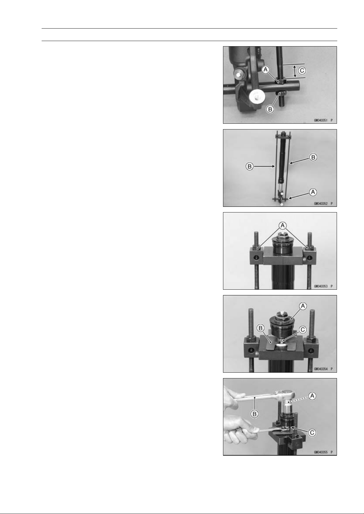
SUSPENSION 13-13
Front Fork
•
Screw the adjust nut [A] onto the compression shaft as
shown in the figure.
•
Screw the locknut [B].
About 20 mm (0.79 in.) [C]
•
Set the other side compression shaft same process.
•
Set the holder bar [A] and compression shafts [B].
•
Screw in the nuts [A] until the piston rod nut comes out.
•
While holding up the top plug [A], insert the fork spring
stopper [B] between the piston rod nut [C] and the slider.
Special Tool - Fork Spring Stopper: 57001-1374
•
Holding the spring preload adjuster [A] with a wrench [B],
loosen the piston rod nut [C].
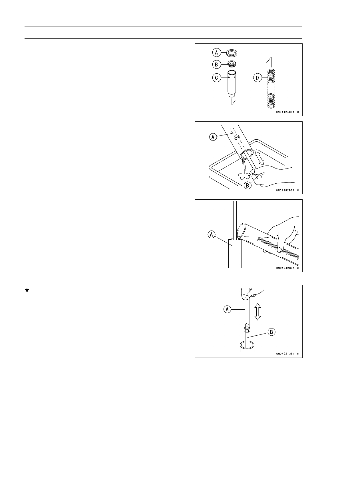
13-14 SUSPENSION
Front Fork
•
Remove:
Top Plug with the Rebound Damping Adjuster Rod
Damper [A]
Slider [B]
Collar [C]
Fork Spring [D]
•
Drain the fork oil into a suitable container.
○
Pump the piston rod [A] up and down at least ten times to
expel the oil from the fork.
Special Tool - Fork Piston Rod Puller, M10 × 1.0 [B]: 57001
-1298
•
Hold the fork tube upright, press the outer tube [A] and
the piston rod all the way down.
•
Pour in the type and amount of fork oil specified.
Suspension Oil - SHOWA SS-47: 44091-0010
Amount (Per Side):
When changing oil:
Approx. 365 mL (12.3 US oz.)
After disassembly and completely dry:
432 ±2.5 mL (14.6 ±0.084 US oz.)
If necessary, measure the oil level as follows.
○
Holdtheinnertubeverticallyinavise.
○
Using the piston rod puller [A], move the piston rod [B] up
and down more than ten times in order to expel all the air
from the fork oil.
Special Tool - Fork Piston Rod Puller, M10 × 1.0: 57001
-1298
○
Remove the piston rod puller.
○
Wait until the oil level settles.
○
With the fork fully compressed and the piston rod fully
pushed in, insert a tape measure or rod into the inner
tube, and measure the distance from the top of the outer
tube to the oil.
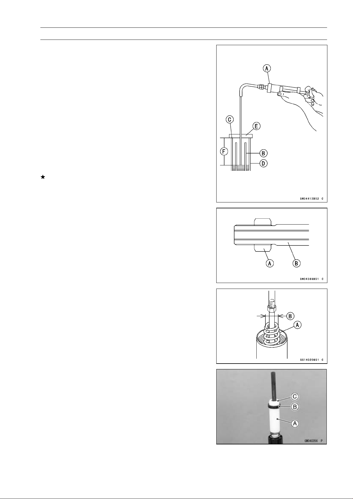
SUSPENSION 13-15
Front Fork
Oil Level (fully compressed, without spring)
Standard:
100±2mm(3.94±0.08in.)(fromthetopoftheouter
tube)
NOTE
○
Fork oil level may also be measured using the fork oil
level gauge.
Special Tool - Fork Oil Level Gauge [A]: 57001-1290
○
With the fork fully compressed and without fork spring,
insert the gauge tube into the inner tube [B] and position
the stopper across the top end [C] of the outer tube [D].
○
Set the gauge stopper [E] so that its lower side shows the
oil level distance specified [F].
○
Pull the handle slowly to pump out the excess oil until the
oil no longer comes out.
If no oil is pumped out, there is insufficient oil in the inner
tube. Pour in enough oil, then pump out the excess oil as
shown above.
•
Screw on the rod nut [A] fully to the piston rod [B].
•
Screw the fork piston rod puller onto the end of the piston
rod.
Special Tool - Fork Piston Rod Puller, M10 × 1.0: 57001
-1298
•
Pull the puller up above the outer tube top.
•
Install the fork spring [A] with the smaller end [B] facing
upward.
•
Install:
Collar [A]
Damper [B]
Slider [C]
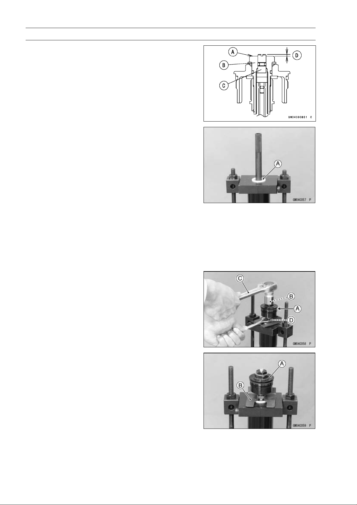
13-16 SUSPENSION
Front Fork
•
Check the distance between the upper end [A] of the
spring preload adjuster [B] and rebound damping adjuster
[C] with a pair of vernier caliper.
1.5 mm (0.059 in.) [D]
•
Set the fork spring compressor on the slider [A] using the
outer tube as a guide.
Special Tools - Fork Spring Compressor: 57001-1587
Clamp: 57001-1693
NOTE
○
Set the cutout of the clamp to the slider.
•
While holding up the piston rod puller, insert the fork
spring stopper between the piston rod nut and the slider.
Special Tool - Fork Spring Stopper: 57001-1374
•
Remove the piston rod puller.
•
Insert the rebound damping adjuster rod into the holes of
the piston rod.
•
Screw in the top plug until it stops onto the piston rod.
•
Check the O-ring [A] on the top plug and replace top plug
with a new one if damaged.
○
Apply grease to the new O-ring.
•
Holding the spring preload adjuster [B] with a wrench [C],
tighten the piston rod nut [D] against the top plug.
Torque - Piston Rod Nuts: 20 N·m (2.0 kgf·m, 15 ft·lb)
•
While holding up the top plug [A], pull out the fork spring
stopper [B].
•
Remove the fork spring compressor.
•
Raise the outer tube and screw the top plug into it.
•
Install the front fork (see Front Fork Installation).
•
Adjust the spring preload (see Spring Preload Adjust-
ment)
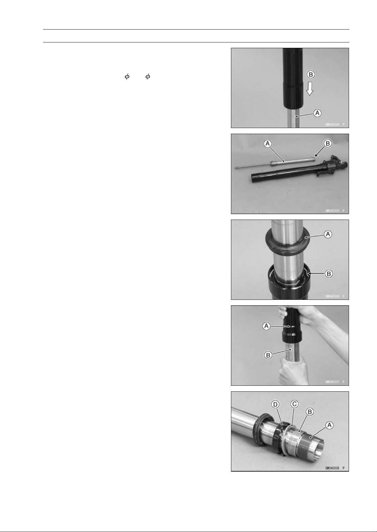
SUSPENSION 13-17
Front Fork
Front Fork Disassembly
•
Remove the front fork (see Front Fork Removal).
•
Drain the fork oil (see Fork Oil Change).
•
Install the suitable pipe ( 26 ∼ 32) [A] into the cylinder
unit.
•
Set the fork leg inverted.
•
While pushing down [B] the fork leg, loosen the bottom
Allen bolt.
•
Remove the Allen bolt and gasket.
•
Take the cylinder unit [A] and center ring plate [B] out of
the inner tube.
○
Do not disassemble the cylinder unit.
•
Separate the inner tube from the outer tube as follows.
○
Slide up the dust seal [A].
○
Remove the retaining ring [B] from the outer tube.
○
Holding the outer tube [A] by hand, pull the inner tube [B]
several times to pull out the outer tube.
•
Remove the inner tube guide bushing [A], outer tube
guide bushing [B], washer [C], oil seal [D] from the inner
tube.
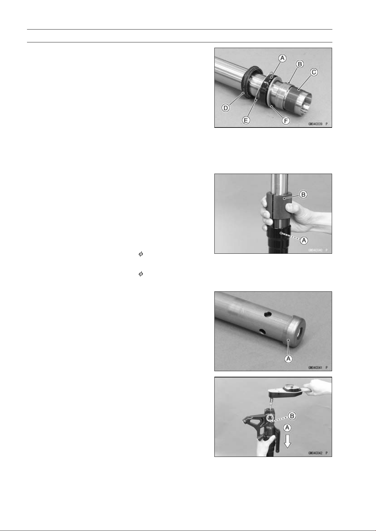
13-18 SUSPENSION
Front Fork
Front Fork Assembly
•
Replace the following parts with new one.
Oil Seal [A]
Outer Tube Guide Bushing [B]
Inner Tube Guide Bushing [C]
Dust Seal [D]
Retaining [E]
Bottom Allen Bolt Gasket
•
Install the following parts onto the inner tube.
Dust Seal
Retaining Ring
Oil Seal
Washer [F]
Outer Tube Guide Bushing
Inner Tube Guide Bushing
•
Insert the inner tube to the outer tube.
•
Fit the new outer tube guide bushing [A] into the outer
tube.
NOTE
○
When assembling the new outer tube guide bushing,
hold the washer against the new outer tube guide bush-
ing and tap the washer with the fork oil seal driver [B]
until it stops.
Special Tool - Fork Oil Seal Driver,
41: 57001-1288
•
Install the oil seal by using the fork oil seal driver.
Special Tool - Fork Oil Seal Driver,
41: 57001-1288
•
Install the retaining ring and dust seal into the outer tube.
•
Install the center ring plate [A] on the cylinder unit.
•
Insert the center ring plate and cylinder unit as a set into
the inner tube.
•
Insert the suitable pipe into the cylinder unit.
•
While pushing down [A] the fork leg, tighten the front fork
bottom Allen bolt [B].
•
Tighten:
Torque - Front Fork Bottom Allen Bolts: 35 N·m (3.6 kgf·m,
26 ft·lb)
•
Pour in the specified type of oil (see Fork Oil Change).
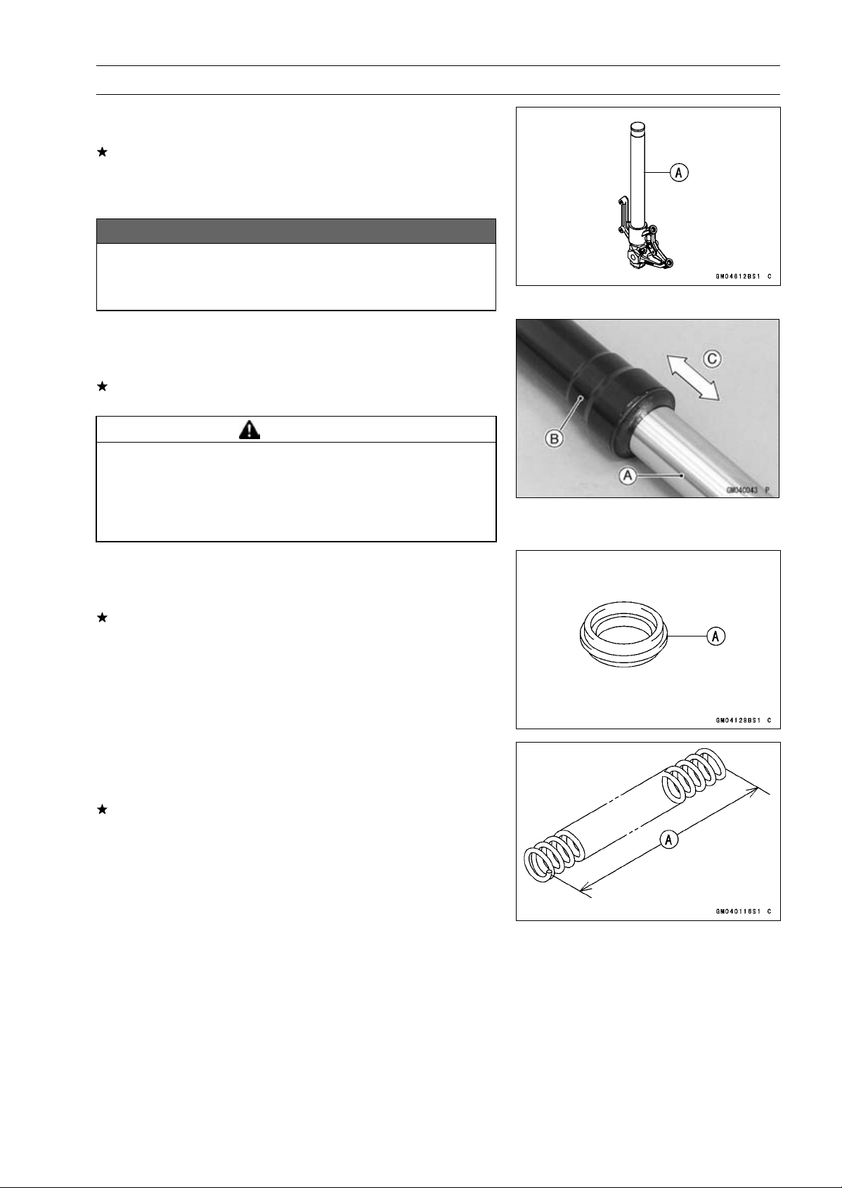
SUSPENSION 13-19
Front Fork
Inner Tube, Outer Tube Inspection
•
Visually inspect the inner tube [A].
If there is any damage, replace the inner tube. Since
damage to the inner tube damages the oil seal and dust
seal, replace the oil seal and dust seal whenever the inner
tube is replaced.
NOTICE
If the inner tube is badly bent or creased, replace
it. Excessive bending, followed by subsequent
straightening, can weaken the inner tube.
•
Temporarily assemble the inner tube [A] and outer tube
[B], and pump [C] them back and forth manually to check
for smooth operation.
If you feel binding or catching, the inner and outer tubes
must be replaced.
WARNING
A straightened inner or outer fork tube may fall in
use, possibly causing an accident resulting in seri-
ous injury or death. Replace a badly bent or dam-
aged inner or outer tube and inspect the other tube
carefully before reusing it.
Dust Seal Inspection
•
Inspect the dust seal [A] for any signs of deterioration or
damage.
Replace it if necessary.
Spring Tension Inspection
•
Since a spring becomes shorter as it weakens, check its
free length [A] to determine its condition.
If the spring of either fork leg is shorter than the service
limit, it must be replaced. If the length of a replacement
spring and that of the remaining spring vary greatly, the
remaining spring should also be replaced in order to keep
the fork legs balanced for motorcycle stability.
Spring Free Length
Standard: 268 mm (10.6 in.)
Service Limit: 263 mm (10.4 in.)
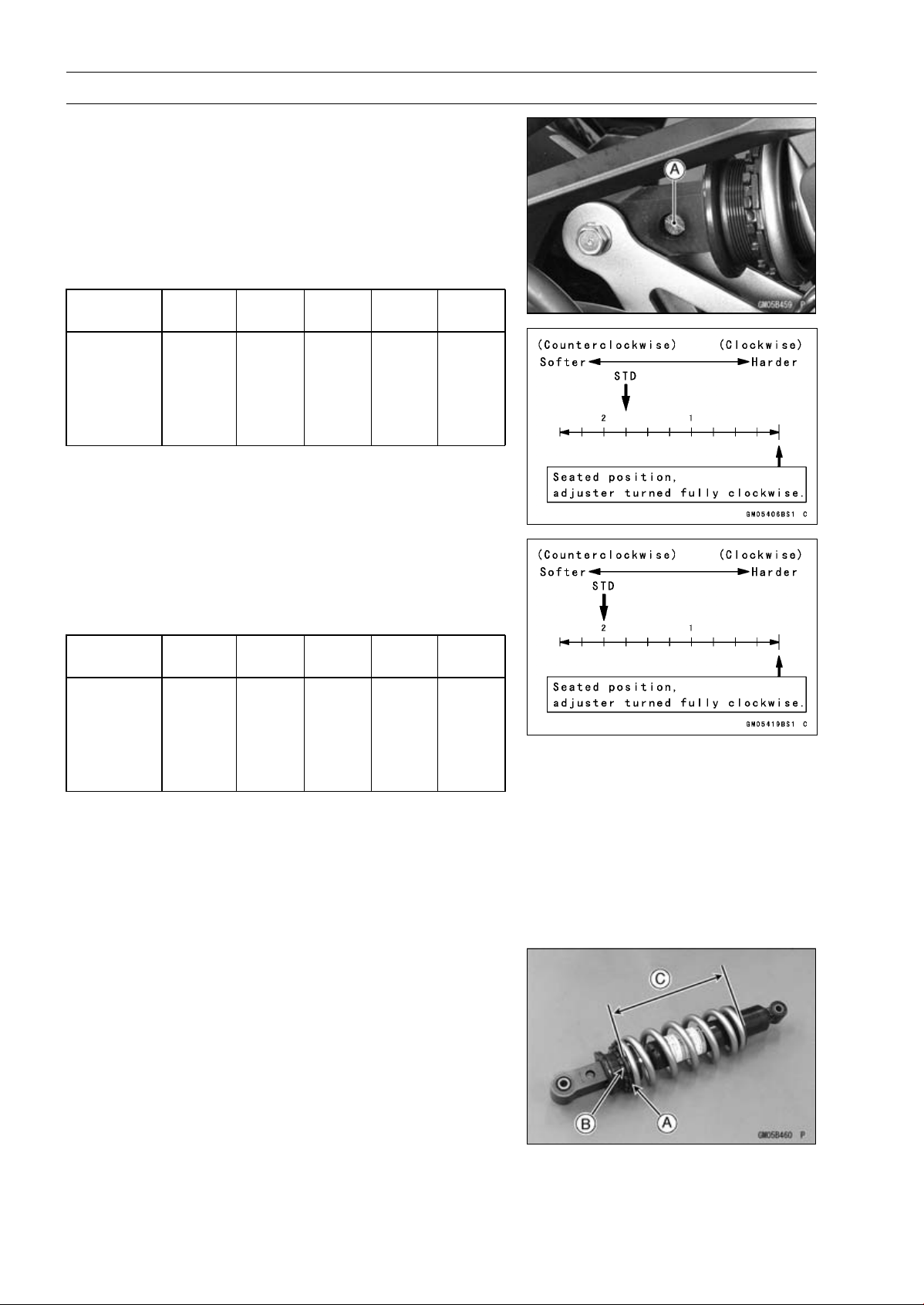
13-20 SUSPENSION
Rear Shock Absorber
Rebound Damping Force Adjustment
•
To adjust the rebound damping force, turn the lower
damping adjuster [A] to the desired position, until you
feel a click.
ZR1000DA/EA
○
The standard adjuster setting is the 13/4turnsoutfrom
the fully clockwise position.
Rebound Damping Force Adjustment
Adjuster
Position
Damping
Force
Setting Load Road Speed
2 1/2 turns
out
Weak Soft Light Good Low
↑ ↑ ↑ ↑ ↑ ↑
↓ ↓ ↓ ↓ ↓ ↓
0
Strong
Hard Heavy Bad High
ZR1000DB ∼/EB ∼
○
The standard adjuster setting is the 2 turns out from the
fully clockwise position.
Rebound Damping Force Adjustment
Adjuster
Position
Damping
Force
Setting Load Road Speed
2 1/2 turns
out
Weak Soft Light Good Low
↑ ↑ ↑ ↑ ↑ ↑
↓ ↓ ↓ ↓ ↓ ↓
0
Strong
Hard Heavy Bad High
Spring Preload Adjustment
•
Remove the rear shock absorber from the frame (see
Rear Shock Absorber Removal).
•
Loosen the locknut and turn out the adjusting nut to free
the spring.
Special Tool - Hook Wrench T=3.2 R37: 57001-1539
•
To adjust the spring preload, turn in the adjusting nut [A]
to the desired position and tighten the locknut [B].
Sp
ring Length [C]
Spring Preload Setting
Standard: Spring length 184.5 mm (7.264 in.)
Usable Range:
Spring length 179.5
∼ 189.5 mm
(7.067
∼ 7.461 in.)
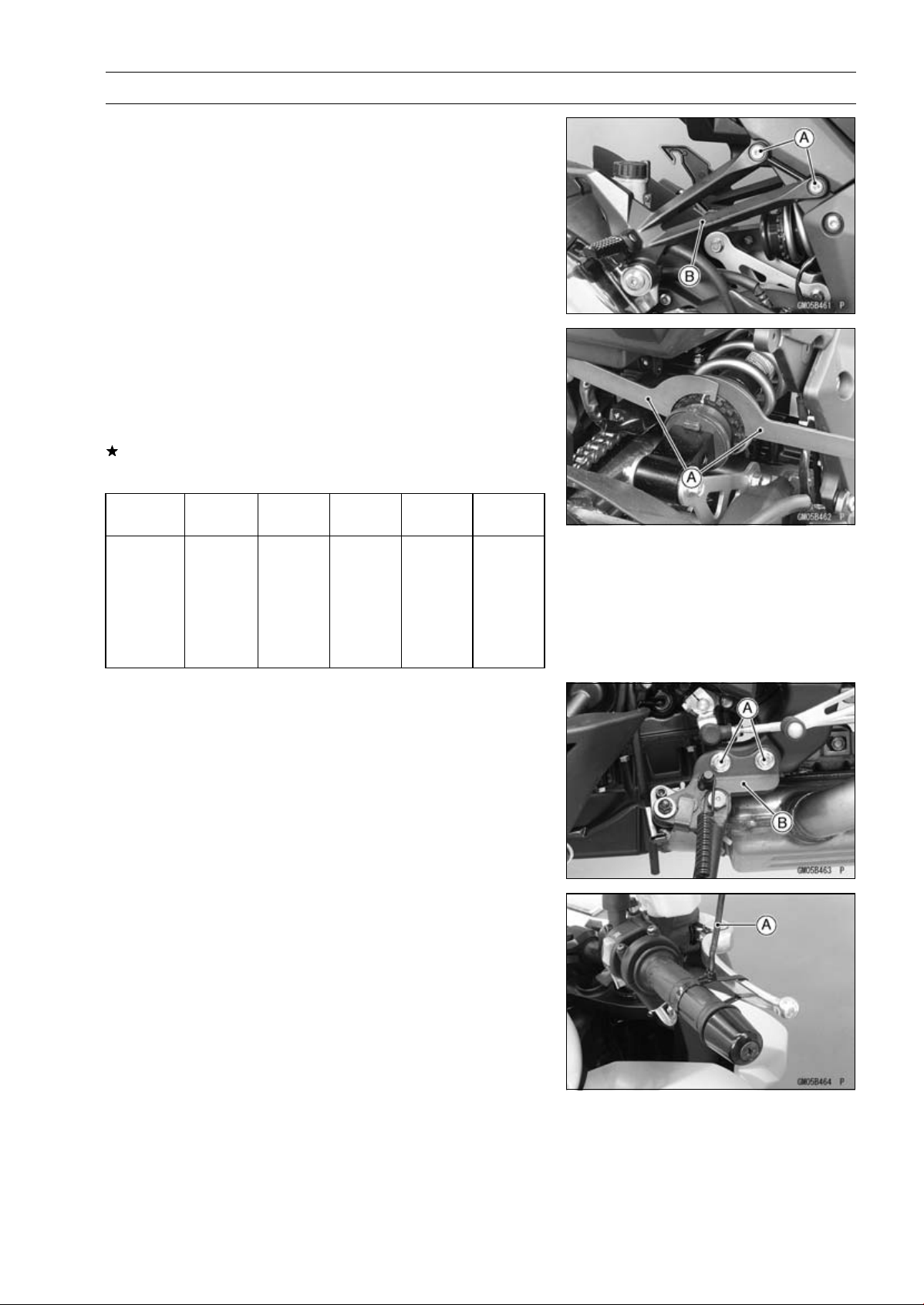
SUSPENSION 13-21
Rear Shock Absorber
•
Remove the bolts [A] and footpeg bracket (both side) [B]
for turning the hook wrench easily.
•
To adjust the spring preload, turn in the adjusting nut to
the desired position and tighten the locknut by using hook
wrenches [A] with the rear shock absorber attached the
frame.
Special Tool - Hook Wrench T=3.2 R37: 57001-1539
If the spring action feels too soft or too stiff, adjust it.
Spring Adjustment
Adjuster
Position
Damping
Force
Setting
Load Road
Speed
189.5 mm
(7.461 in.)
Weak
Soft
Light
Good
Low
↑ ↑ ↑ ↑ ↑ ↑
↓ ↓ ↓ ↓ ↓ ↓
179.5 mm
(7.067 in.)
Strong Hard Heavy Bad High
Rear Shock Absorber Removal
•
Support the motorcycle with the stand.
•
Remove:
Bolts [A]
Sidestand Bracket [B] with the Sidestand
•
Squeeze the brake lever slowly and hold it with a band
[A].
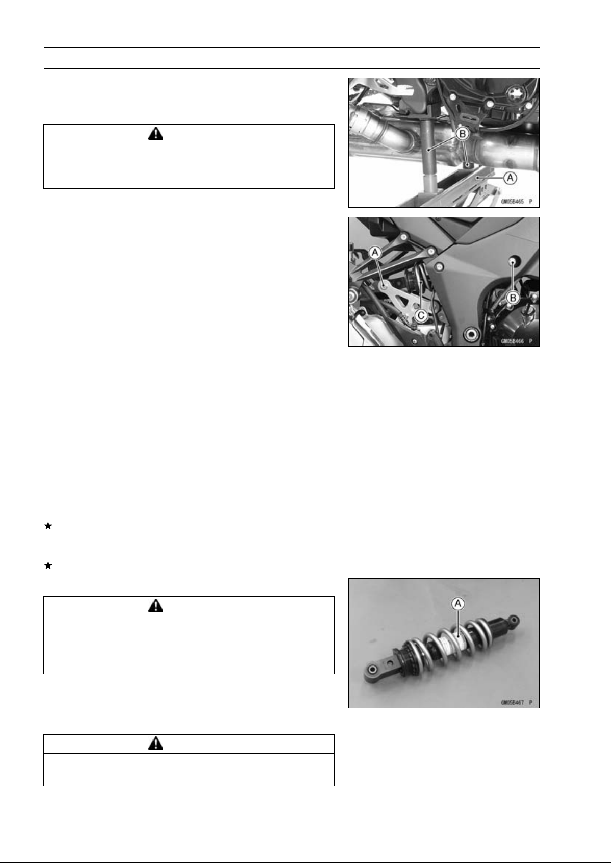
13-22 SUSPENSION
Rear Shock Absorber
•
Raise the rear wheel off the ground with the jack.
Special Tools - Jack [A]: 57001-1238
Jack Attachment [B]: 57001-1608
WARNING
Be sure to hold the front brake when removing the
shock absorber, or the motorcycle may fall over. It
could cause an accident and injury.
•
Remove:
Lower Rear Shock Absorber Nut and Bolt [A]
Upper Rear Shock Absorber Bolt [B]
•
Remove the rear shock absorber [C] from rearside.
Rear Shock Absorber Installation
•
Tighten:
Torque - Rear Shock Absorber Bolt and Nut (Upper and
Lower ): 34 N·m (3.5 kgf·m, 25 ft·lb)
Rear Shock Absorber Inspection
•
Remove the rear shock absorber (see Rear Shock Ab-
sorber Removal).
•
Visually inspect the following items.
Smooth Stroke
Oil Leakage
Crack or Dent
If there is any damage to the rear shock absorber, replace
it.
•
Visually inspect the rubber bushing.
If it show any signs of damage, replace it.
Rear Shock Absorber Scrapping
WARNING
Since the reservoir tank of the rear shock absorber
contains nitrogen gas, do not incinerate the reser-
voir tank without first releasing the gas or it may
explode.
•
Remove the rear shock absorber (see Rear Shock Ab-
sorber Removal).
•
Drill the cylinder [A] of the rear shock absorber using
about 2 mm (0.08 in.) drill bit.
WARNING
Since the high pressure gas is dangerous, do not
point the valve toward your face or body.
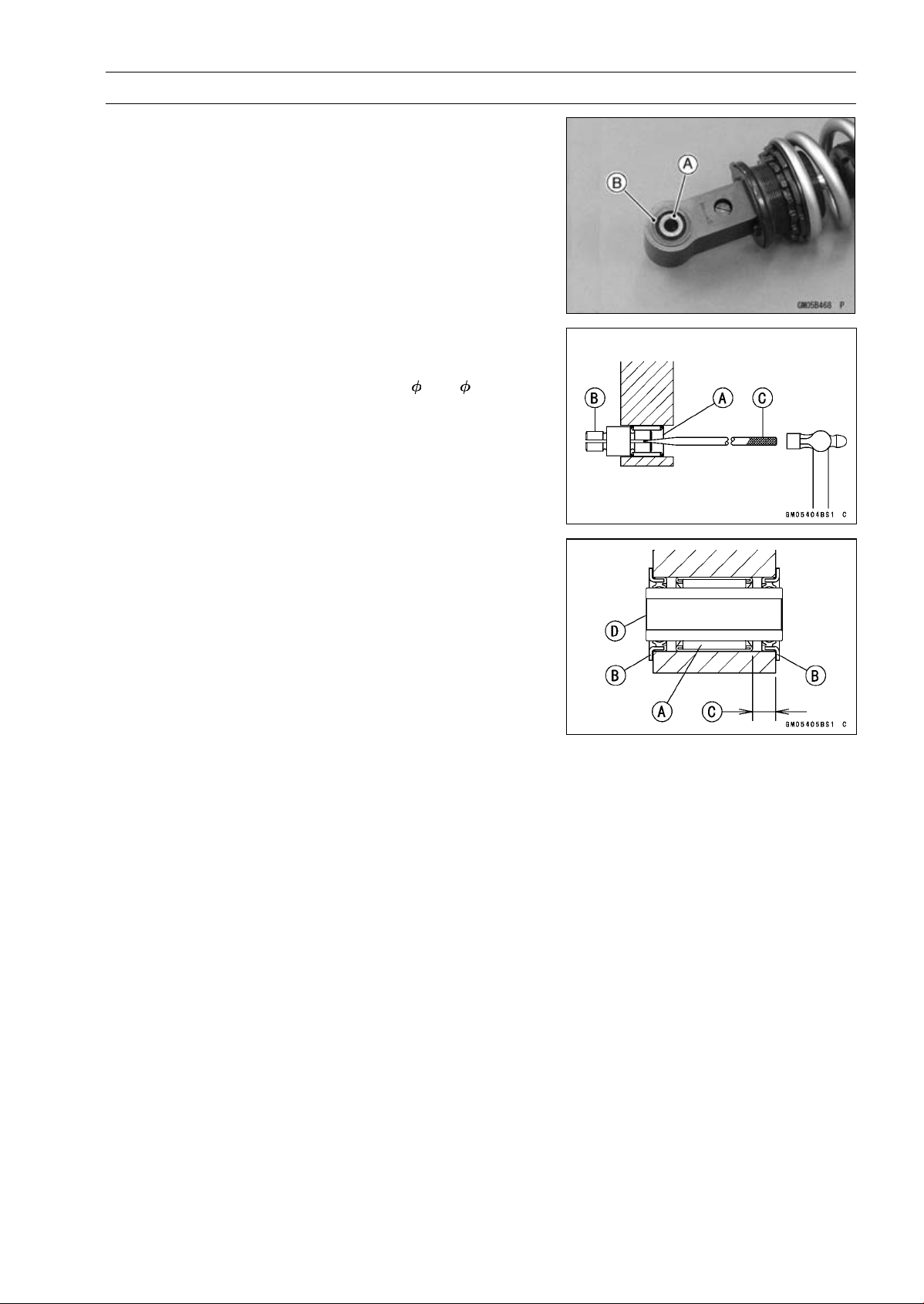
SUSPENSION 13-23
Rear Shock Absorber
Rear Shock Absorber Bearing Removal
•
Remove:
Rear Shock Absorber (see Rear Shock Absorber Re-
moval)
Sleeve [A]
Grease Seals [B]
•
Remove the needle bearing [A], using the bearing re-
mover head [B] and bearing remover shaft [C].
Special Tools - Bearing Remover Head,
15 × 17: 57001
-1267
Bearing Remover Shaft: 57001-1377
Rear Shock Absorber Bearing Installation
•
Replace the needle bearing [A] and grease seals [B] with
new ones.
•
Apply plenty of grease to the lips of the grease seals.
•
Install the needle bearing position as shown.
[C] 7.5 mm (0.30 in.)
•
Install the grease seals and sleeve [D].
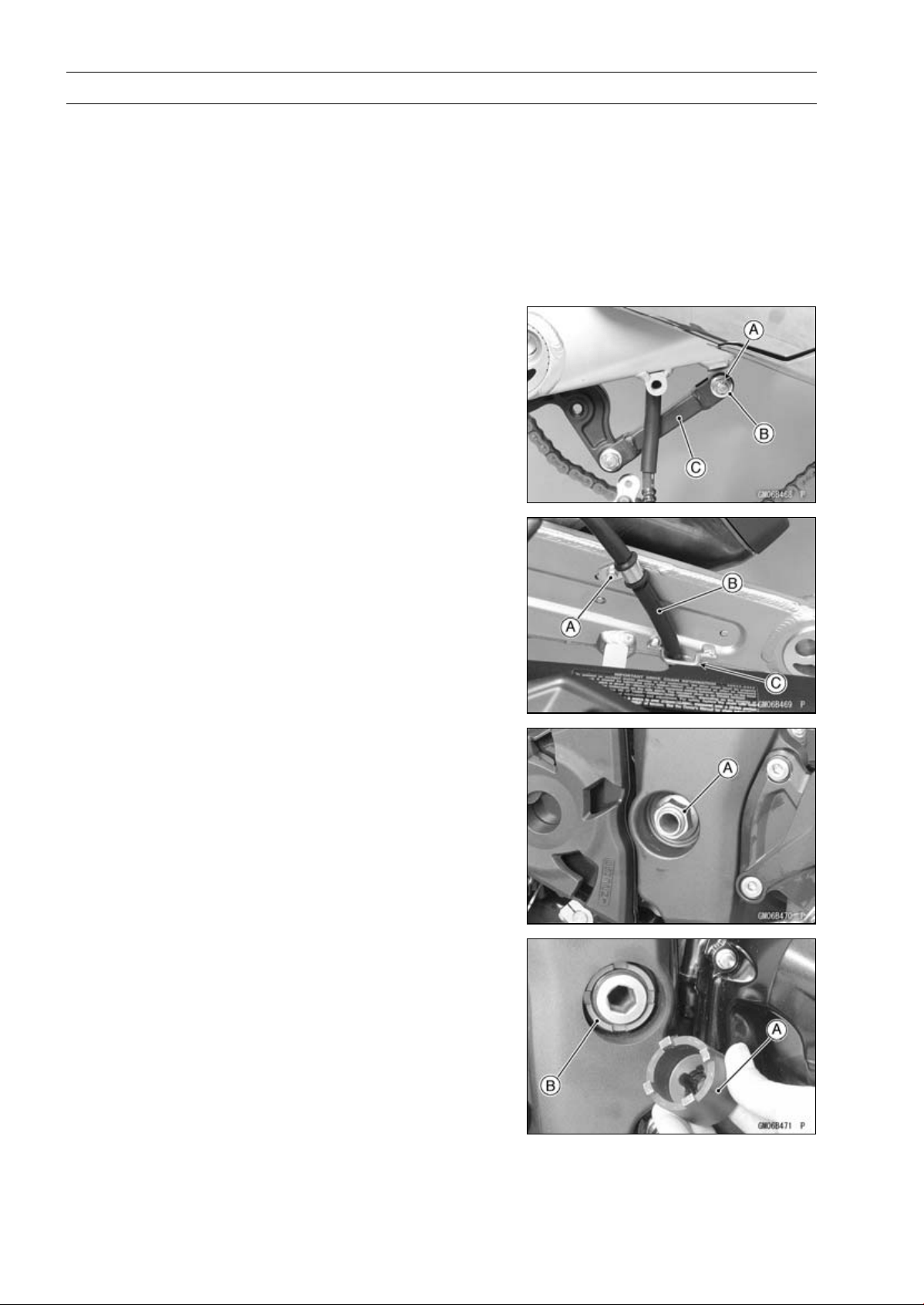
13-24 SUSPENSION
Swingarm
Swingarm Removal
•
Remove:
Rear Brake Hose Lower End (see Rear Caliper Removal
in the Brakes chapter)
Rear Wheel (see Rear Wheel Removal in the
Wheels/Tires chapter)
Mud Guard (see Mad Guard Removal in the Frame
chapter)
Rocker Arm (see Rocker Arm Removal)
•
Remove:
Cotter Pin [A]
Bolt and Nut [B]
•
Move the torque link [C] downward.
•
Remove:
Brake Hose Clamp Bolt [A]
•
Clear the brake hose [B] from the guide [C] on the
swingarm.
•
Unscrew the swingarm pivot shaft nut [A].
•
Using the swingarm pivot nut wrench [A], loosen the
swingarm pivot adjusting collar locknut [B].
Special Tool - Swingarm Pivot Nut Wrench: 57001-1597
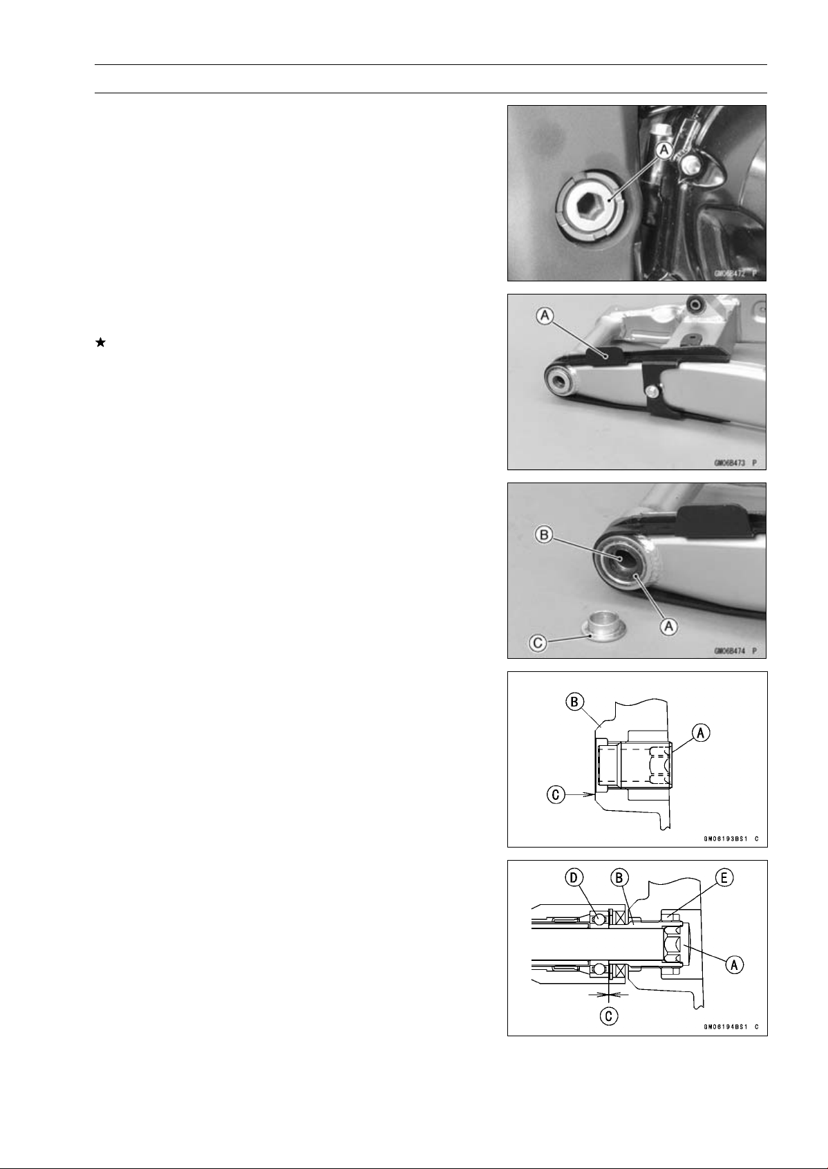
SUSPENSION 13-25
Swingarm
•
Turn the swingarm pivot shaft [A] counterclockwise to free
the adjusting collar from the swingarm.
○
Make the gap between the adjusting collar and swingarm.
•
Pull out the pivot shaft to the right side and remove the
swingarm.
Swingarm Installation
•
Visually inspect the chain guide [A].
Replace the chain guide if it shows any signs of abnormal
wear or damage.
•
Apply grease to the lips of the grease seals [A].
•
Be sure to install the grease seals and sleeve [B] to the
swingarm.
•
Fit the collar [C] on the grease seal of the left side.
•
Screw the swingarm pivot adjusting collar [A] into the
frame [B] so that the collar does not project the swingarm
mating surface [C].
•
Install the swingarm and insert the swingarm pivot shaft
[A] into the adjusting collar [B] from the right side, and
tighten the pivot shaft.
NOTE
○
Tighten the swingarm pivot shaft until the clearance [C]
between the ball bearing [D] and collar comes to 0 mm
(0 in.).
Torque - Swingarm Pivot Shaft: 20 N·m (2.0 kgf·m, 15 ft·lb)
•
Using the swingarm pivot nut wrench, tighten the
swingarm pivot adjusting collar locknut [E].
Special Tool - Swingarm Pivot Nut Wrench: 57001-1597
Torque - Swingarm Pivot Adjusting Collar Locknut: 98 N·m
(10 kgf·m, 72 ft·lb)
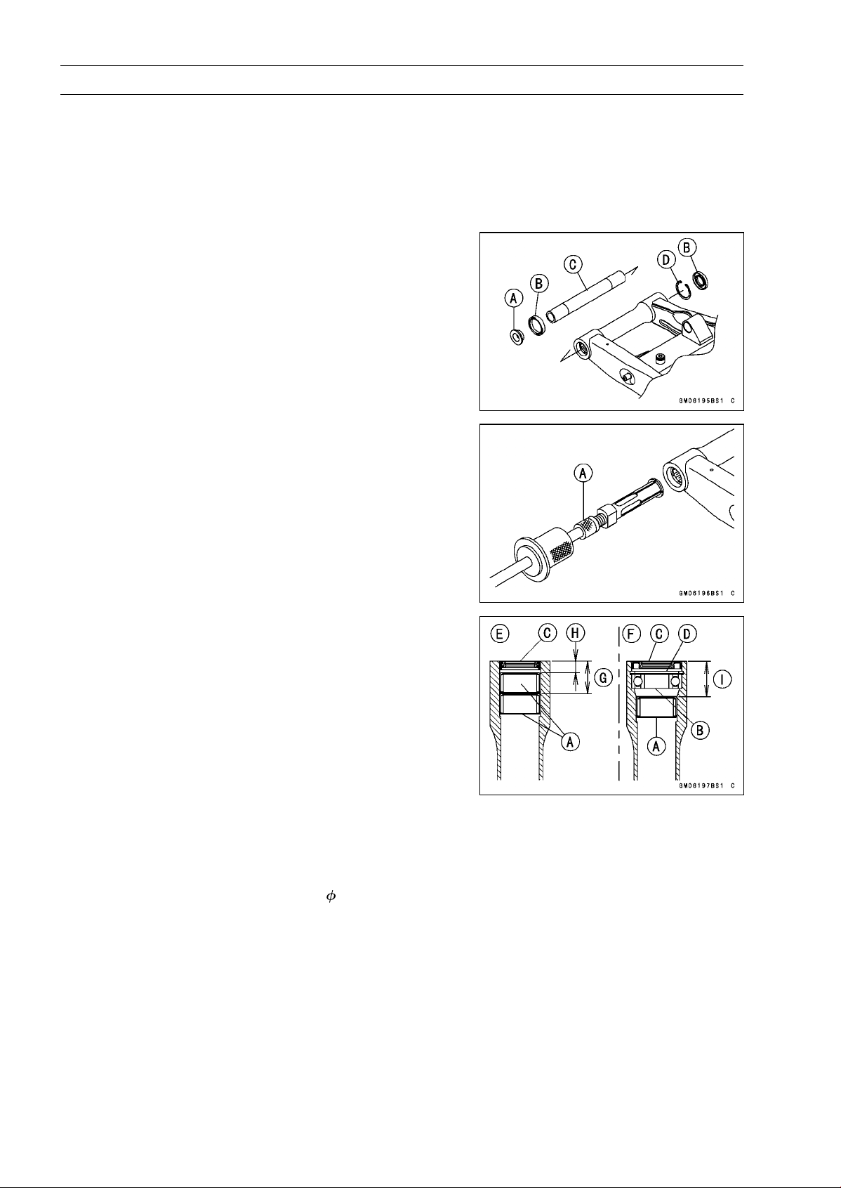
13-26 SUSPENSION
Swingarm
•
Tighten the swingarm pivot shaft nut.
Torque - Swingarm Pivot Shaft Nut: 108 N·m (11.0 kgf·m,
79.7 ft·lb)
•
Move the swingarm up and down to check for abnormal
friction.
•
Install the removed parts (see appropriate chapters).
Swingarm Bearing Removal
•
Remove:
Swingarm (see Swingarm Removal)
Collar [A]
Grease Seals [B]
Sleeve [C]
Circlip (Right Side) [D]
Special Tool - Inside Circlip Pliers: 57001-143
•
Remove the ball bearing and needle bearings.
Special Tool - Oil Seal & Bearing Remover [A]: 57001-1058
Swingarm Bearing Installation
•
Replace the needle bearings [A], ball bearing [B], grease
seals [C] and circlip [D] with new ones.
•
Install the needle bearings as shown in the figure.
[E] Left Side
[F] Right Side
[G]27mm(1.1in.)
[H] 9.5 mm (0.37 in.)
[I] 29.5 mm (1.16 in.)
NOTE
○
Install the needle bearings so that the marked side
faces out.
Special Tool - Needle Bearing Driver, 28: 57001-1610
○
Press in the ball bearing until it bottomed.
Special Tool - Bearing Driver Set: 57001-1129
○
Install the circlip.
Special Tool - Inside Circlip Pliers: 57001-143
○
Press in the grease seals so that seal surface is flushed
with the end of housing.
Special Tool - Bearing Driver Set: 57001-1129
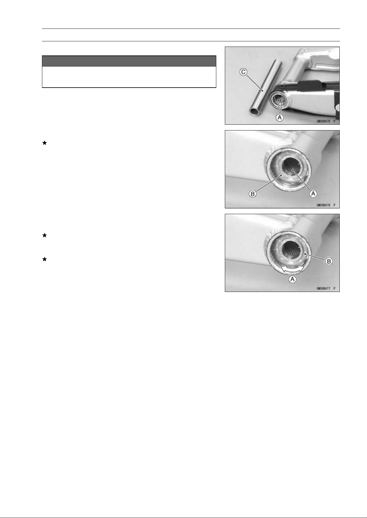
SUSPENSION 13-27
Swingarm
Swingarm Bearing, Sleeve Inspection
NOTICE
Do not remove the bearings for inspection. Re-
moval may damage them.
•
Inspect the needle bearings [A] and ball bearing [B] in-
stalled in the swingarm.
○
The rollers and ball in a bearing normally wear very little,
and wear is difficult to measure. Instead of measuring,
visually inspect the bearing for abrasion, discoloration, or
other damage.
If the needle bearing and sleeve [C] show any sings of
abnormal wear, discoloration, or damage, replace them
as a set.
•
Turn the bearing in the swingarm back and forth [A] while
checking for plays, roughness, or binding.
If bearing play, roughness, or binding is found, replace
the bearing.
•
Examine the bearing seal [B] for tears or leakage.
If the seal is torn or is leaking, replace the bearing.
Swingarm Bearing Lubrication
NOTE
○
Since the bearings are packed with grease and sealed,
lubrication is not required.
Chain Guide Inspection
•
Refer to the Chain Guide Wear Inspection in the Periodic
Maintenance chapter.
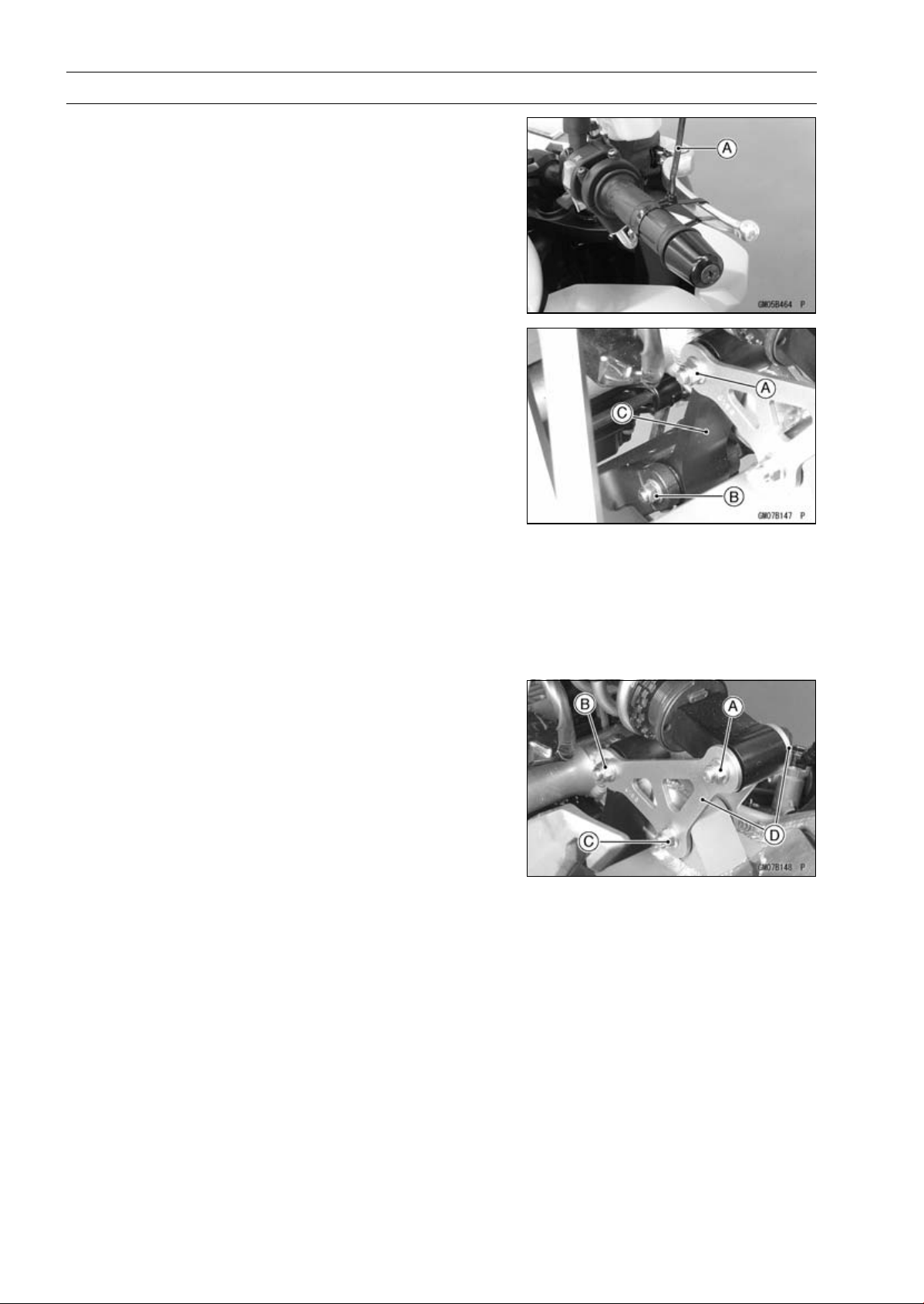
13-28 SUSPENSION
Tie-Rod, Rocker Arm
Tie-Rod Removal
•
Remove:
Mud Guard (see Mud Guard Removal in the Frame
chapter)
•
Squeeze the brake lever slowly and hold it with a band
[A].
•
Raise the rear wheel off the ground with the jack (see
Rear Shock Absorber Removal).
Special Tools - Jack: 57001-1238
Jack Attachment: 57001-1608
•
Remove:
Upper Tie-Rod Bolt and Nut [A]
Lower Tie-Rod Bolt and Nut [B]
Tie-Rod [C]
Tie-Rod Installation
•
Apply grease to the inside of the grease seals.
•
Install the tie-rod.
•
Replace the tie-rod nuts with new ones.
•
Tighten:
Torque - Tie-Rod Nuts: 34 N·m (3.5 kgf·m, 25 ft·lb)
Rocker Arm Removal
•
Remove:
Mud Guard (see Mud Guard Removal in the Frame
chapter)
•
Squeeze the brake lever slowly and hold it with a band.
•
Raise the rear wheel off the ground with the jack (see
Rear Shock Absorber Removal).
Special Tools - Jack: 57001-1238
Jack Attachment: 57001-1608
•
Remove:
Lower Rear Shock Absorber Bolt and Nut [A]
Upper Tie-Rod Bolt and Nut [B]
Rocker Arm Bolt and Nut [C]
Rocker Arms [D]
Rocker Arm Installation
•
Apply grease to the inside of the oil seals.
•
Replace the rocker arm nut and rear shock absorber nut
respective new one.
•
Tighten:
Torque - Rocker Arm Nut: 34 N·m (3.5 kgf·m, 25 ft·lb)
Tie-Rod Nuts: 34 N·m (3.5 kgf·m, 25 ft·lb)
Rear Shock Absorber Nut (Lower): 34 N·m (3.5
kgf·m, 25 ft·lb)
•
Install the removed parts (see appropriate chapters).
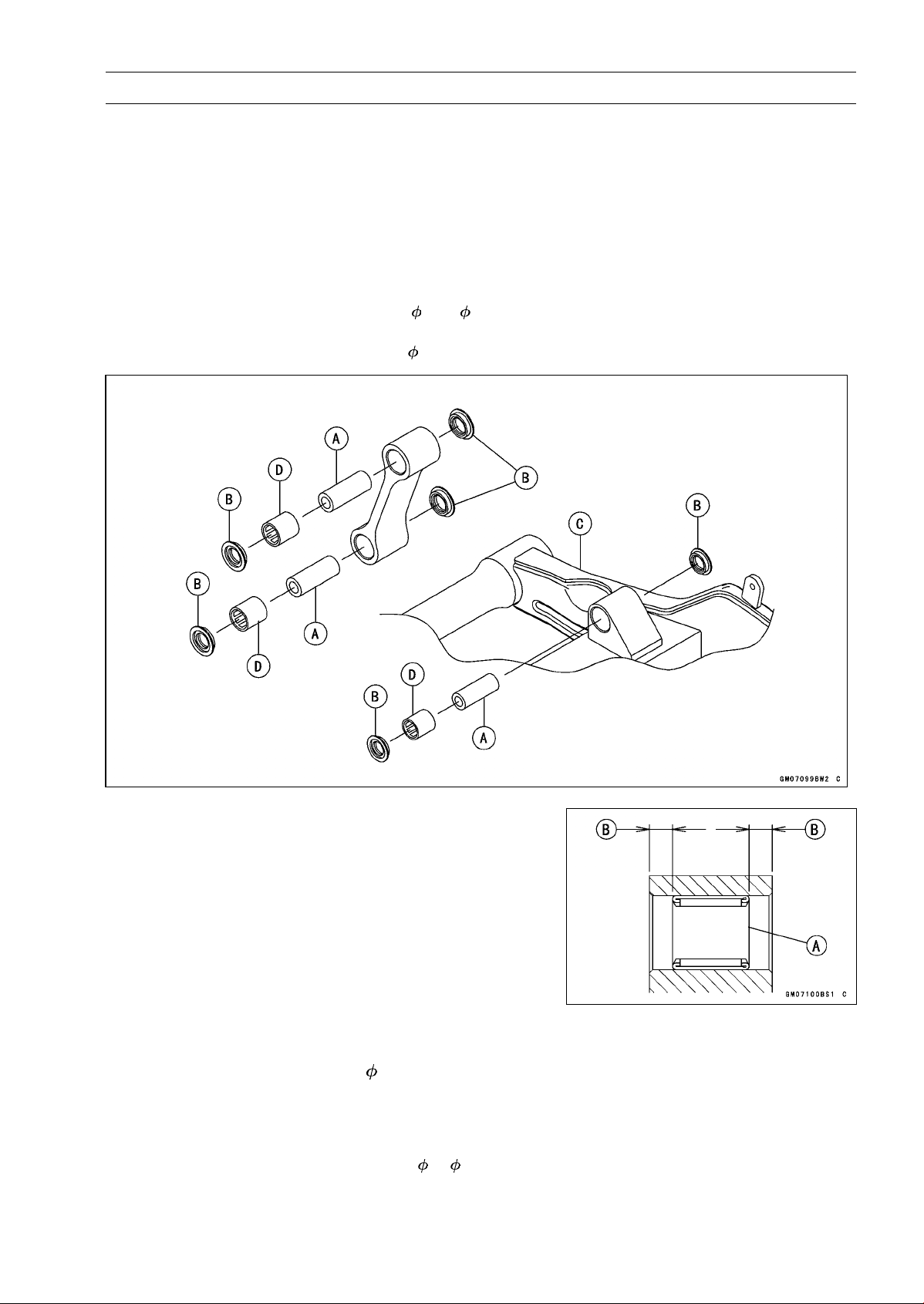
SUSPENSION 13-29
Tie-Rod, Rocker Arm
Tie-Rod and Rocker Arm Bearing Removal
•
Remove:
Tie-Rods (see Tie-Rod Removal)
Rocker Arm (see Rocker Arm Removal)
Sleeves [A]
Oil Seals [B]
Swingarm [C] (see Swingarm Removal)
•
Remove the needle bearings [D], using the bearing re-
mover head and bearing remover shaft.
Special Tools - Bearing Remover Head,
15 × 17: 57001
-1267
Bearing Remover Shaft,
13: 57001-1377
Tie-Rod and Rocker Arm Bearing Installation
•
Replace the needle bearing [A] and oil seals with new
ones.
•
Apply 2-stroke oil to the inside of the tie-rod.
•
Apply plenty of grease to the lips of the oil seals.
•
Install the needle bearings and oil seals position as shown
in the figure.
○
Screw the needle bearing driver into the driver holder.
○
Insert the needle bearing driver into the needle bearing
and press the needle bearing.
7.5 mm (0.30 in.) [B]
NOTE
○
For a bearing of inner diameter
17, select the pressing
side of the needle bearing driver according to its press-
ing depth.
Special Tools - Bearing Driver Set: 57001-1129
Needle Bearing Driver,
17/ 18: 57001
-1609
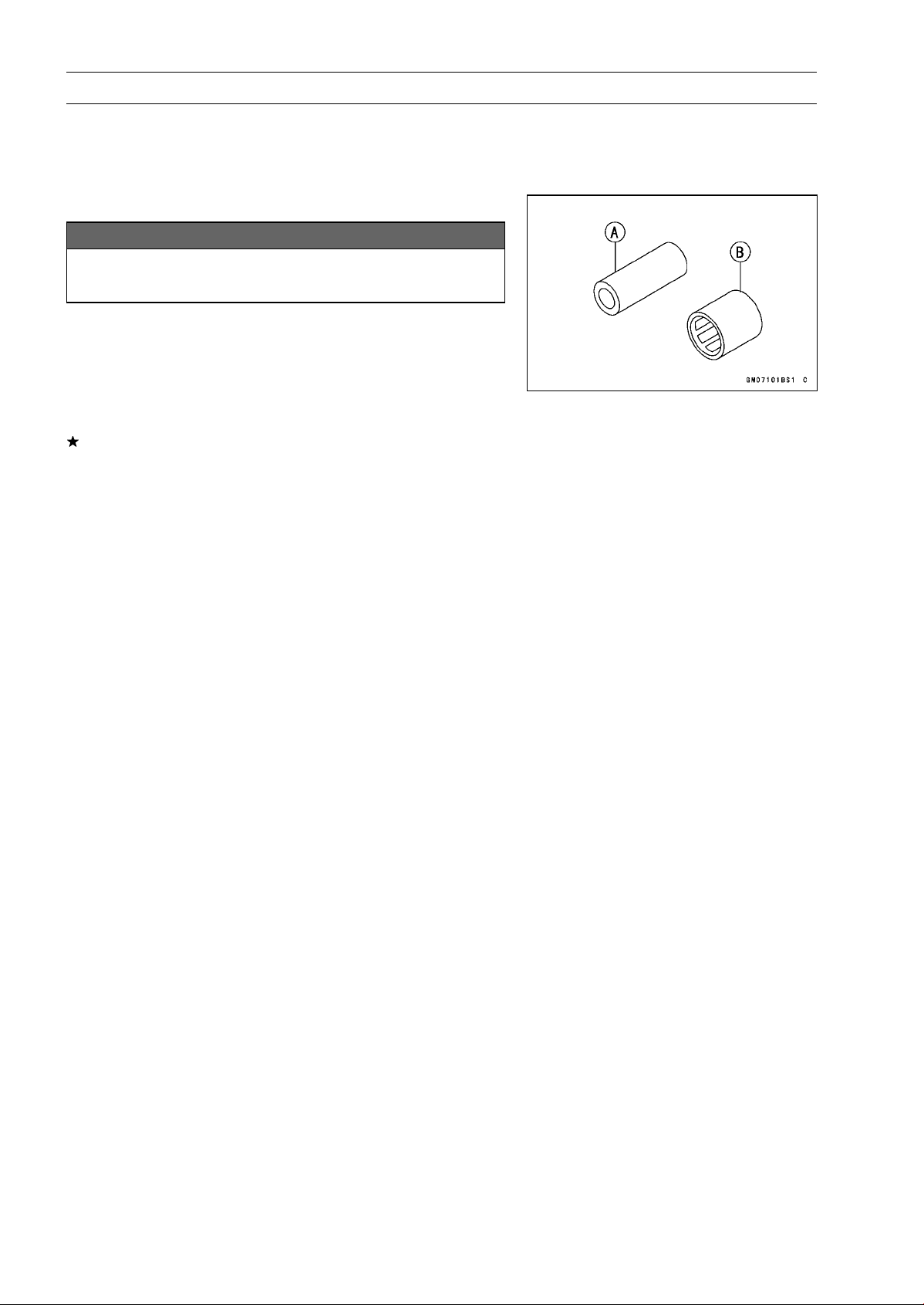
13-30 SUSPENSION
Tie-Rod, Rocker Arm
NOTE
○
Install the needle bearings so that the marked side
faces in.
Rocker Arm/Tie-Rod Bearing, Sleeve Inspection
NOTICE
Do not remove the bearings for inspection. Re-
moval may damage them.
•
Visually inspect the rocker arm, or tie-rod sleeves [A] and
needle bearings [B].
•
The rollers in a needle bearing normally wear very little,
and wear is difficult to measure. Instead of measuring,
inspect the bearing for abrasion, color change, or other
damage.
If there is any doubt as to the condition of any of the nee-
dle bearings or sleeve, replace the sleeve and needle
bearings as a set.
Rocker Arm/Tie-Rod Bearing Lubrication
NOTE
○
Since the bearings are packed with grease, lubrication
is not required.

STEERING 14-1
14
Steering
Table of Contents
Exploded View........................................................................................................................ 14-2
Special Tools .......................................................................................................................... 14-4
Steering .................................................................................................................................. 14-5
Steering Inspection ........................................................................................................... 14-5
Steering Adjustment.......................................................................................................... 14-5
Steering Stem......................................................................................................................... 14-6
Stem, Stem Bearing Removal........................................................................................... 14-6
Stem, Stem Bearing Installation........................................................................................ 14-7
Steering Stem Bearing Lubrication ................................................................................... 14-9
Steering Stem Warp Inspection ........................................................................................ 14-9
Stem Cap Deterioration, Damage Inspection ................................................................... 14-9
Handlebar............................................................................................................................... 14-10
Handlebar Removal .......................................................................................................... 14-10
Handlebar Installation ....................................................................................................... 14-11
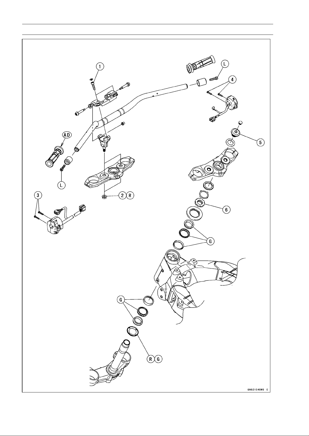
14-2 STEERING
Exploded View

STEERING 14-3
Exploded View
Torque
No. Fastener
N·m kgf·m ft·lb
Remarks
1 Handlebar Holder Bolts 25 2.5 18
2 Handlebar Holder Nuts 34 3.5 25 R
3
Left Switch Housing Screws
3.5 0.36 31 in·lb
4 Right Switch Housing Screws 3.5 0.36 31 in·lb
5 Steering Stem Head Bolt 108 11.0 79.7
6 Steering Stem Nut 25 2.5 18
AD: Apply adhesive.
G: Apply grease.
R: Replacement Parts
L: Apply a non-permanent locking agent.
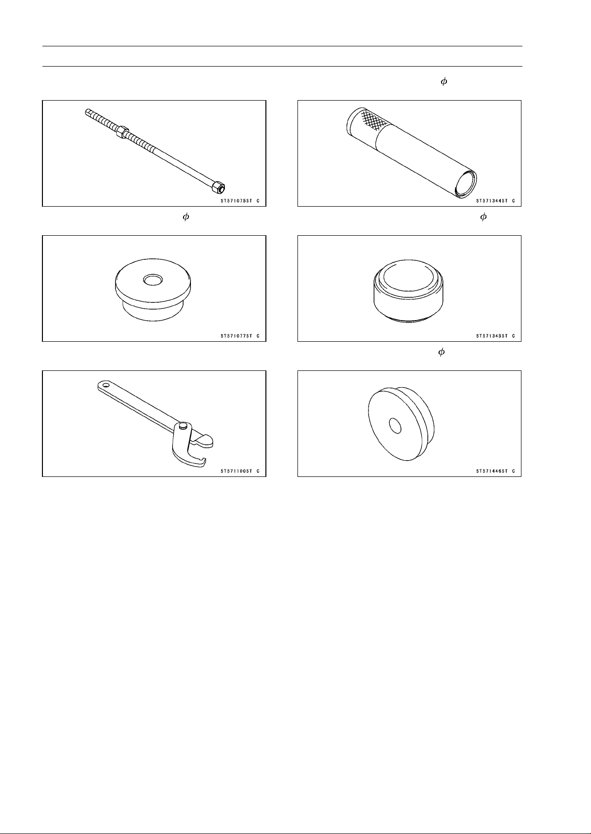
14-4 STEERING
Special Tools
Head Pipe Outer Race Press Shaft:
57001-1075
Head Pipe Outer Race Driver, 54.5:
57001-1077
Steering Stem Nut Wrench:
57001-1100
Steering Stem Bearing Driver, 42.5:
57001-1344
Steering Stem Bearing Driver Adapter, 41.5:
57001-1345
Head Pipe Outer Race Driver, 55:
57001-1446

STEERING 14-5
Steering
Steering Inspection
•
Refer to the Steering Play Inspection in the Periodic Main-
tenance chapter.
Steering Adjustment
•
Refer to the Steering Play Adjustment in the Periodic
Maintenance chapter.
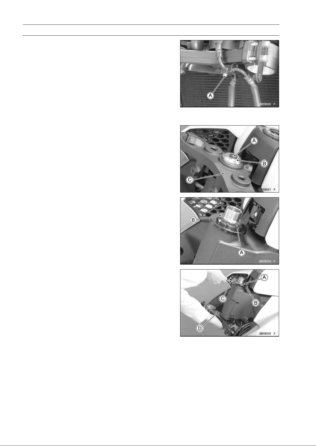
14-6 STEERING
Steering Stem
Stem, Stem Bearing Removal
•
Remove:
Upper Fairing (see Upper Fairing Removal in the Frame
chapter)
Upper Fairing Bracket (see Upper Fairing Bracket Re-
moval in the Frame chapter)
Meter Unit (see Meter Unit Removal in the Electrical Sys-
tem chapter)
Handlebar (see Handlebar Removal)
Front Forks (see Front Fork Removal in the Suspension
chapter)
Brake Hose Fitting Bolt [A]
•
Remove:
Steering Stem Head Bolt Plug [A]
Steering Stem Head Bolt [B] and Washer
Steering Stem Head [C]
•
Bend the claws [A] of claw washer back.
•
Remove the steering stem locknut [B].
Special Tool - Steering Stem Nut Wrench: 57001-1100
•
Remove the claw washer.
•
Pushing up the stem base, and remove the steering stem
nut [A] with stem cap [B].
Special Tool - Steering Stem Nut Wrench [C]: 57001-1100
•
Remove:
Steering Stem [D]
Upper Ball Bearing Inner Race and Ball Bearing
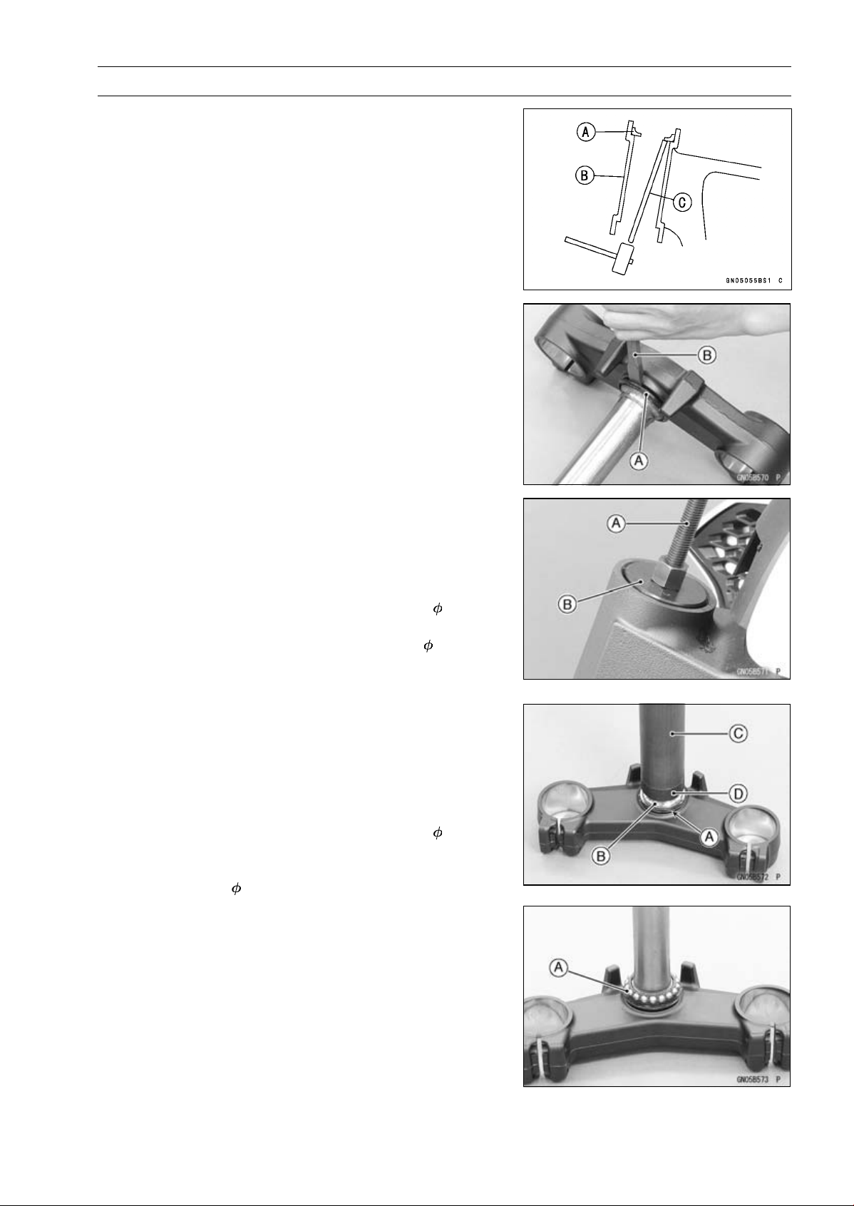
STEERING 14-7
Steering Stem
•
To remove the ball bearing outer races [A] pressed into
the head pipe [B], insert a bar [C] into the recesses of
head pipe, and applying it to both recess alternately ham-
merittodrivetheraceout.
NOTE
○
If either steering stem bearing is damaged, it is recom-
mended that both the upper and lower bearings (includ-
ing outer races) should be replaced with new ones.
•
Remove the lower ball bearing inner race (with its oil seal)
[A] which is pressed onto the steering stem with a suitable
commercially available chisel [B].
Stem, Stem Bearing Installation
•
Replace the bearing outer races with new ones.
•
Drivethemintotheheadpipeatthesametime.
Special Tools - Head Pipe Outer Race Press Shaft [A]:
57001-1075
Head Pipe Outer Race Driver,
54.5 [B]:
57001-1077
Head Pipe Outer Race Driver,
55: 57001
-1446
•
Apply grease to the outer races.
•
Replace the bearing inner races and oil seal with new
ones.
•
Apply grease to the oil seal.
•
Install the oil seal [A] on the steering stem, and drive the
lower ball bearing inner race [B] applied the grease onto
the stem.
Special Tools - Steering Stem Bearing Driver,
42.5 [C]:
57001-1344
Steering Stem Bearing Driver Adapter,
41.5 [D]: 57001-1345
•
Install the lower ball bearing [A] onto the stem.
•
Grease the following.
Inner and Outer Races
Lower and Upper Ball Bearings
○
The lower and upper ball bearings are identical.
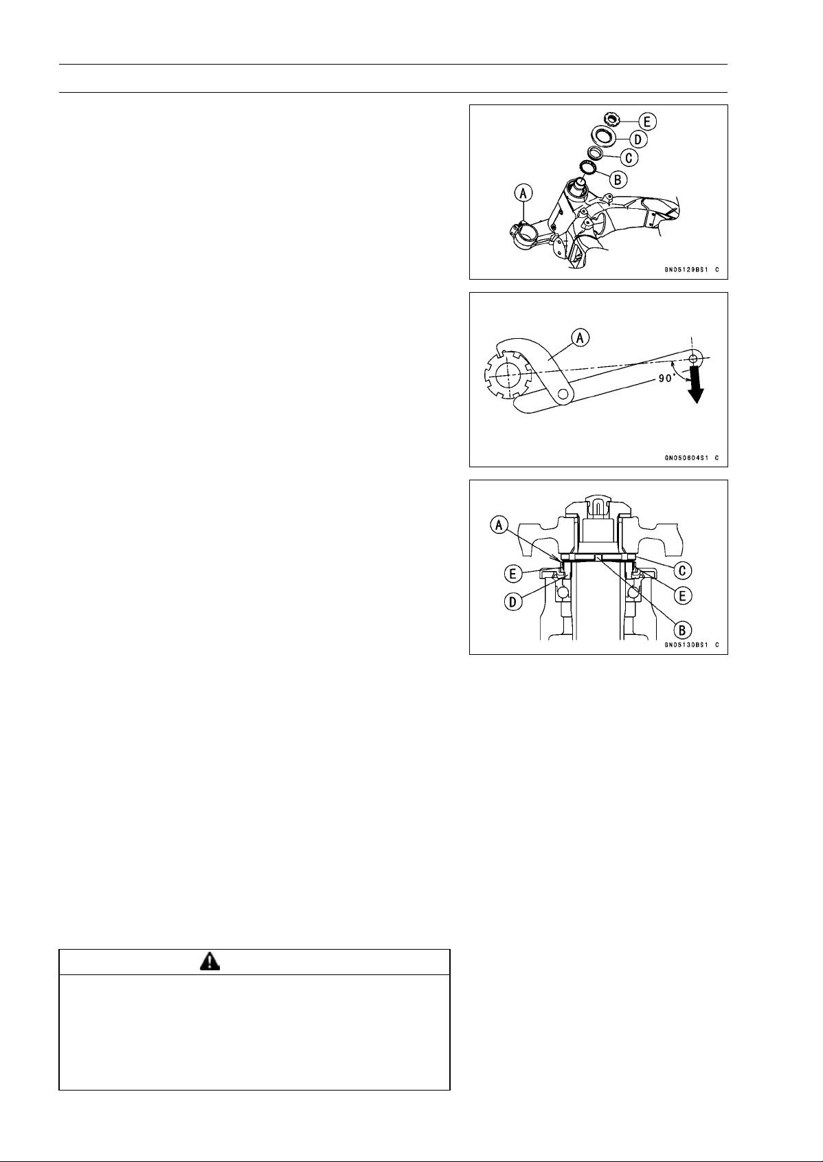
14-8 STEERING
Steering Stem
•
Install the stem [A] through the head pipe and install the
ball bearing [B] and inner race [C] on it.
•
Install:
Stem Cap [D]
Steering Stem Nut [E]
•
Settle the bearings in place as follows.
○
Tighten the steering stem nut with 55 N·m (5.6 kgf·m, 41
ft·lb) of torque first, and loosen it a fraction of a turn until
it turns lightly. Afterward tighten it again with specified
torque using a steering stem nut wrench [A].
Special Tool - Steering Stem Nut Wrench: 57001-1100
Torque - Steering Stem Nut: 25 N·m (2.5 kgf·m, 18 ft·lb)
•
Install the claw washer [A] so that its bent side [B] faces
upward, and engage the bent claws with the grooves of
stem locknut [C].
•
Hand tighten the stem locknut until the claw washer
touches the steering stem nut.
•
Tighten the stem locknut clockwise until the claws are
aligned with the grooves (ranging from 2nd to 4th) of stem
nut [D], and bend the 2 claws downward [E].
•
Install the stem head.
•
Install the washer, and temporary tighten the steering
stem head bolt.
•
Install the front forks (see Front Fork Installation in the
Suspension chapter).
NOTE
○
Tighten the lower front fork clamp bolts first, next the
stem head bolt, last the upper front fork clamp bolts.
○
Tighten the front fork clamp bolts (upper and lower) al-
ternately two times to ensure even tightening torque.
Torque - Upper Front Fork Clamp Bolts: 20 N·m (2.0 kgf·m,
15 ft·lb)
Steering Stem Head Bolt: 108 N·m (11.0 kgf·m,
79.7 ft·lb)
Lower Front Fork Clamp Bolts: 25 N·m (2.5 kgf·m,
18 ft·lb)
WARNING
If the handlebar does not turn to the steering stop it
may cause an accident resulting in injury or death.
Be sure the cables,harnesses and hoses are routed
properly and do not interfere with handlebar move-
ment (see Cable, Wire, and Hose Routing section in
the Appendix chapter).
•
Install the removed parts (see appropriate chapters).
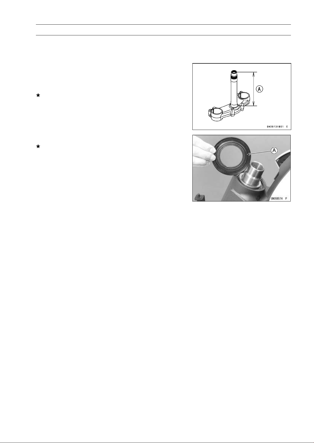
STEERING 14-9
Steering Stem
Steering Stem Bearing Lubrication
•
Refer to the Steering Stem Bearing Lubrication in the Pe-
riodic Maintenance chapter.
Steering Stem Warp Inspection
•
Whenever the steering stem is removed, or if the steering
can not be adjusted for smooth action, check the steering
stem for straightness.
If the steering stem [A] is bent, replace the steering stem.
Stem Cap Deterioration, Damage Inspection
Replace the stem cap if its oil seal [A] shows damage.
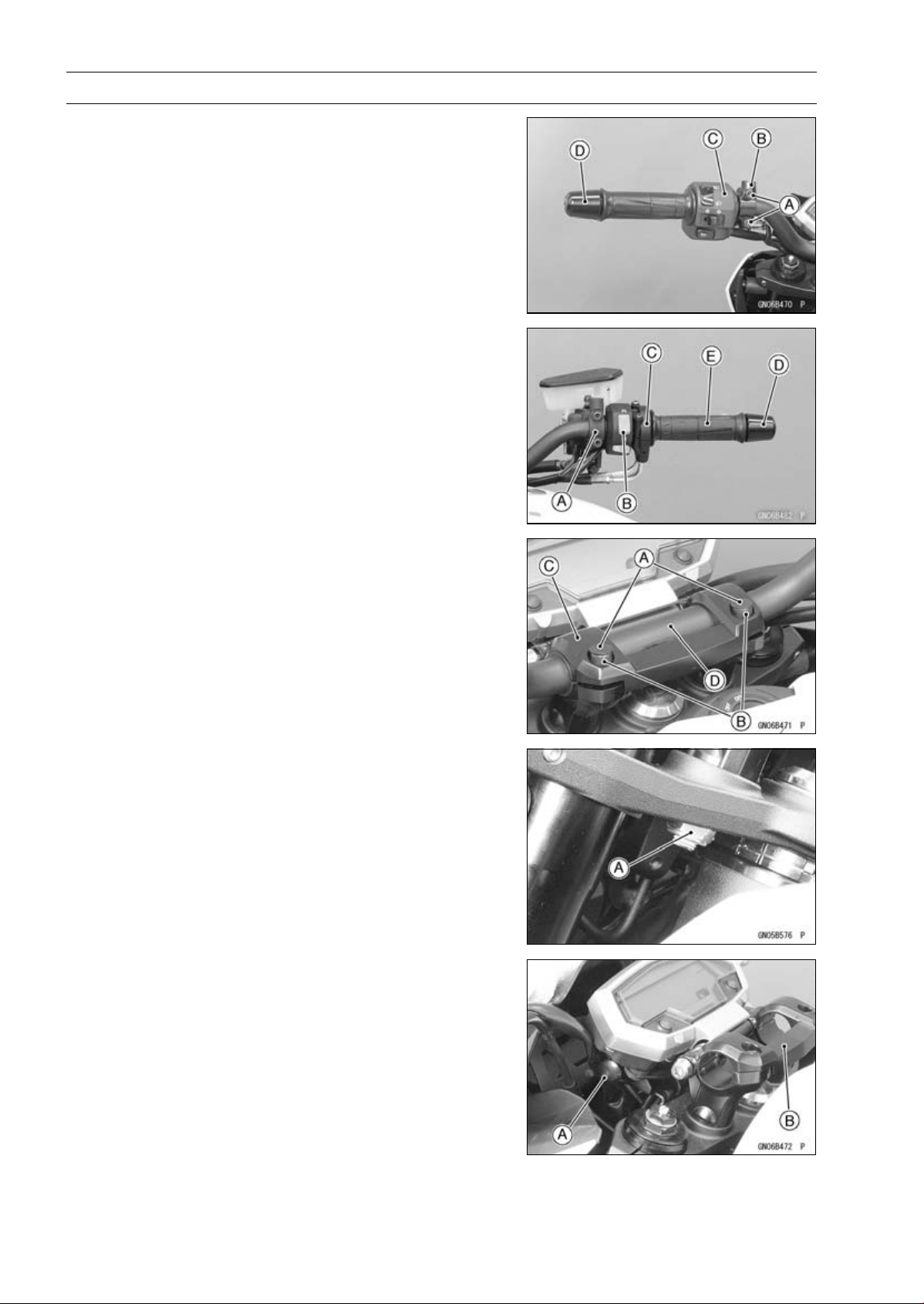
14-10 STEERING
Handlebar
Handlebar Removal
•
Remove:
Rear View Mirrors (see Rear View Mirrors Removal in
the Frame chapter)
Clutch Lever Clamp Bolts [A]
Clutch Lever Assembly [B]
Left Switch Housing [C]
Handlebar Weight [D]
•
Remove:
Front Master Cylinder [A] (see Front Master Cylinder Re-
moval in the Brakes chapter)
Right Switch Housing [B]
Throttle Case [C]
Handlebar Weight [D]
Throttle Grip [E]
•
Remove:
Handlebar Holder Plugs [A]
Handlebar Holder Bolts [B]
•
Open the handlebar holder [C], and then pull out the han-
dlebar [D].
•
Remove:
Handlebar Holder Nuts [A] (Both Sides)
•
While pulling the meter unit angle adjusting knob [A], re-
move the handlebar holder [B] upward.
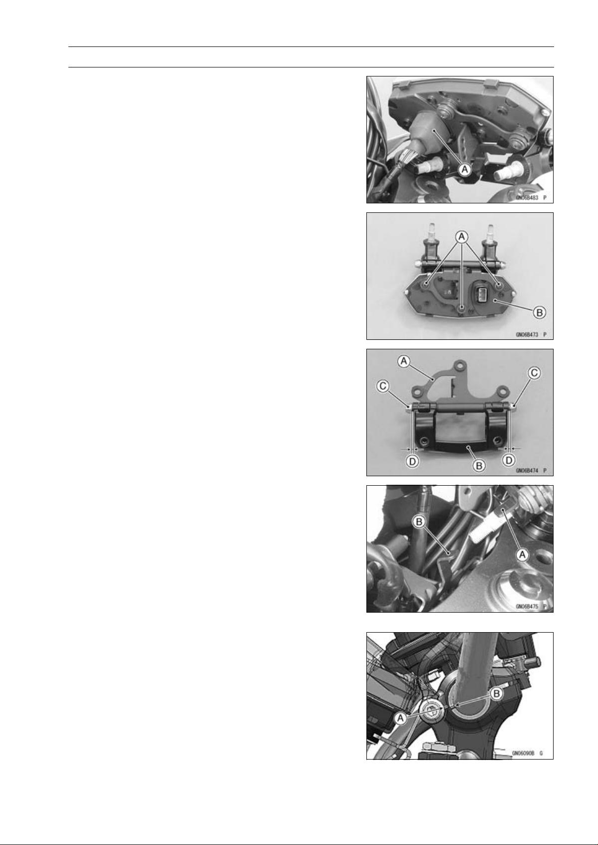
STEERING 14-11
Handlebar
•
Side the dust cover [A] to disconnect the meter unit con-
nector.
•
Remove:
Meter Unit Mounting Screws [A]
Meter Unit [B]
Handlebar Installation
•
Assemble the meter unit bracket [A] and handlebar holder
[B] as shown.
○
Insert the pins [C] with the gap [D] of the pin and holder
less than 1.2 mm (0.047 in.).
•
Install the meter unit.
•
Tighten:
Torque - Meter Unit Mounting Screws: 1.2 N·m (0.12 kgf·m,
11 in·lb)
•
Connect the meter connector.
•
Install the handlebar holder so that the meter unit projec-
tion [A] set under the upper fairing bracket projection [B].
•
Replace the handlebar holder nuts with new ones.
•
Tighten:
Torque - Handlebar Holder Nuts: 34 N·m (3.5 kgf·m, 25 ft·lb)
•
For US and Canada models, set the handlebar so that the
upper front edge [A] of the slit in the handle barbracket is
aligned with the upper front edge [B] of the lower handle-
bar holder as shown in the figure.
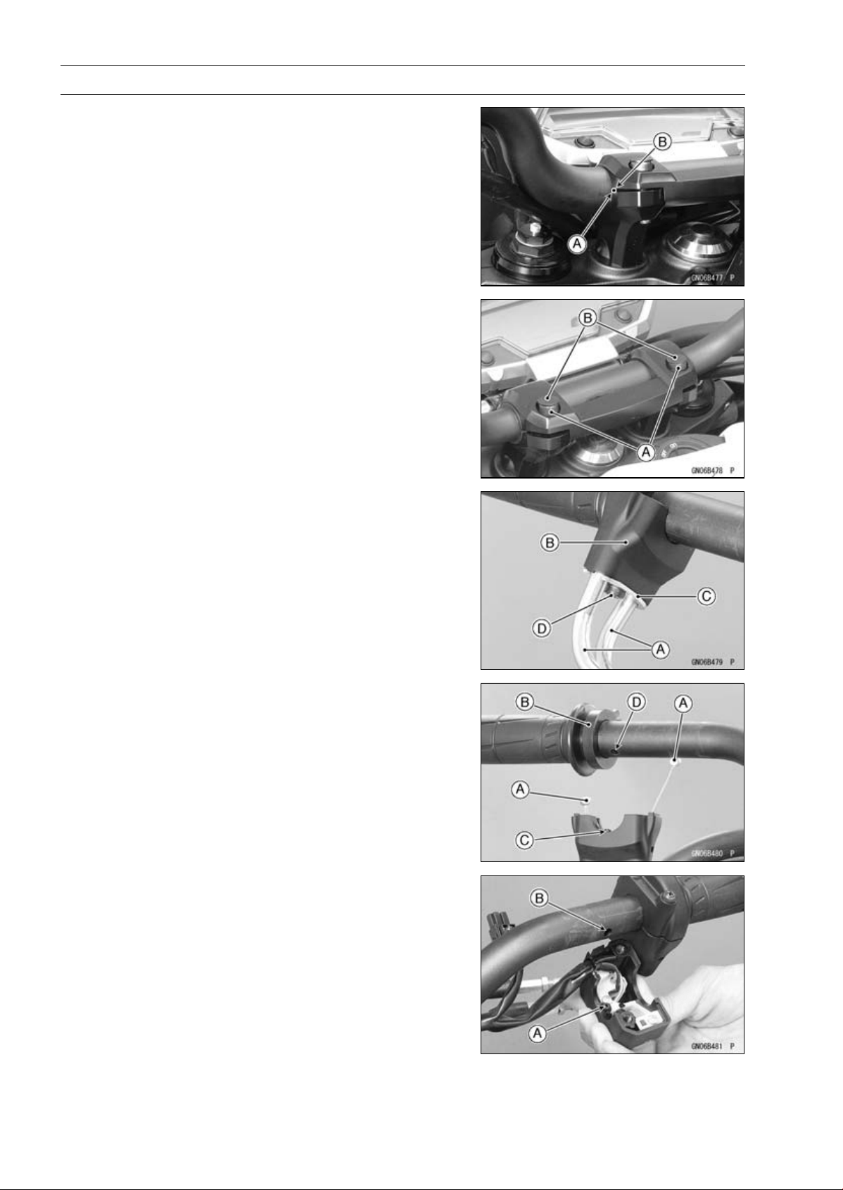
14-12 STEERING
Handlebar
•
For other than US and CA models, align the punch mark
[A] on the handlebar and the corner edge [B] on the upper
holder.
•
Tighten:
Torque - Handlebar Holder Bolts [A]: 25 N·m (2.5 kgf·m, 18
ft·lb)
•
Install the handlebar holder plugs [B].
•
Apply adhesive cement to the inside of the left handlebar
grip.
•
Insert the throttle cables [A] into the throttle case [B].
•
Install the throttle cable holder plate [C].
•
Tighten the holder plate screw [D].
•
Install the throttle cable tips [A] to the throttle grip [B].
○
Fit the projection [C] into a hole [D] in the handlebar.
•
Apply a non-permanent locking agent to the threads of
the handlebar weight screws, and tighten them.
•
Install the left and right switch housings.
○
Fit the projection [A] into a hole [B] in the handlebar.
Torque - Switch Housing Screws: 3.5 N·m (0.36 kgf·m, 31
in·lb)
•
Install:
Front Master Cylinder (see Front Master Cylinder Instal-
lation in the Brakes chapter)
Clutch Lever Assembly (see Clutch Lever Assembly In-
stallation in the Clutch chapter)

FRAME 15-1
15
Frame
Table of Contents
Exploded View................................... 15-2
Seats ................................................. 15-9
Rear Seat Removal...................... 15-9
Rear Seat Installation................... 15-9
Front Seat Removal ..................... 15-9
Front Seat Installation .................. 15-9
Fairings.............................................. 15-10
Lower Fairing Removal................ 15-10
Lower Fairing Installation ............. 15-10
Rear Lower Fairing Removal ....... 15-10
Rear Lower Fairing Installation .... 15-11
Center Fairing Removal............... 15-11
Center Fairing Installation ............ 15-11
Windshield Removal .................... 15-12
Windshield Installation ................. 15-12
Upper Fairing Removal................ 15-12
Upper Fairing Disassembly.......... 15-13
Upper Fairing Assembly............... 15-13
Upper Fairing Installation ............. 15-13
Upper Fairing Bracket Removal... 15-13
Upper Fairing Bracket Installation 15-14
Inner Fairing Removal.................. 15-14
Inner Fairing Installation............... 15-14
Side Covers....................................... 15-15
Side Cover Removal.................... 15-15
Side Cover Installation................. 15-15
Seat Covers....................................... 15-16
Seat Cover Removal.................... 15-16
Seat Cover Installation................. 15-16
Fenders ............................................. 15-17
Front Fender Removal................. 15-17
Front Fender Installation.............. 15-17
Flap and Rear Fender Removal... 15-18
Flap and Rear Fender Installation 15-19
Frame ................................................ 15-20
Frame Inspection ......................... 15-20
Rear Frame Removal................... 15-20
Rear Frame Installation................ 15-20
Rear Frame Bracket Removal ..... 15-20
Rear Frame Bracket Installation .. 15-20
Battery Case...................................... 15-21
Battery Case Removal................. 15-21
Battery Case Installation.............. 15-21
Guard................................................. 15-22
Mud Guard Removal.................... 15-22
Mud Guard Installation................. 15-22
Sidestand........................................... 15-23
Sidestand Removal...................... 15-23
Sidestand Installation................... 15-23
Rear View Mirrors.............................. 15-24
Rear View Mirrors Removal
(ZR1000DA/EA) ........................ 15-24
Rear View Mirrors Installation
(ZR1000DA/EA) ........................ 15-24
Rear View Mirrors Removal
(ZR1000DB ∼/EB ∼) .................. 15-24
Rear View Mirrors Installation
(ZR1000DB ∼/EB ∼) .................. 15-25
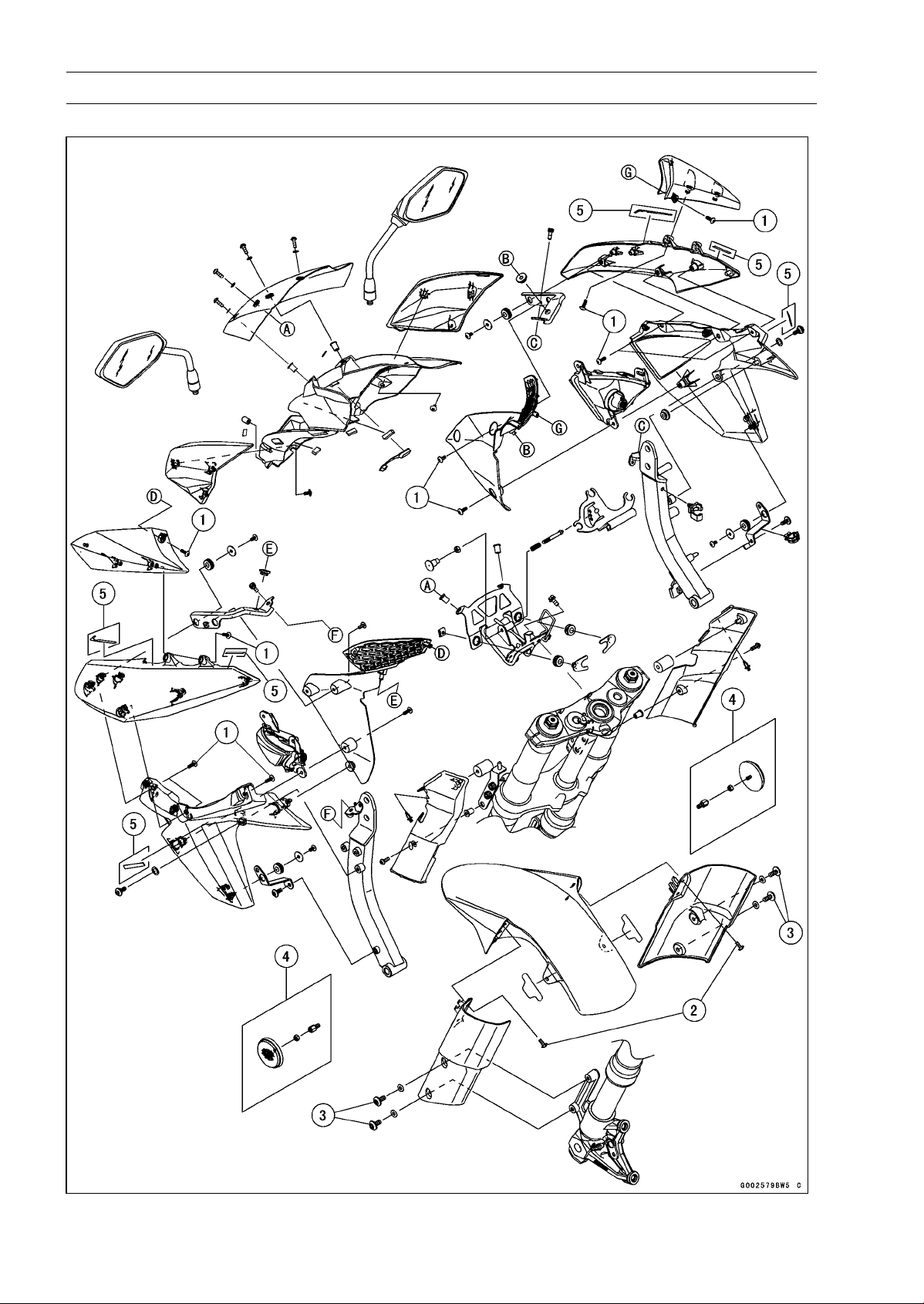
15-2 FRAME
Exploded View
ZR1000DA/EA

FRAME 15-3
Exploded View
Torque
No. Fastener
N·m
kgf·m ft·lb
Remarks
1
Center Fairing Assembly Screws
1.2 0.12 11 in·lb
2 Front Fender Assembly Screws 1.2 0.12 11 in·lb
3 Front Fender Mounting Bolts 3.9 0.40 35 in·lb
4. Reflectors (US, CA, and CAL Models)
5. ZR1000DA/EA Early Model
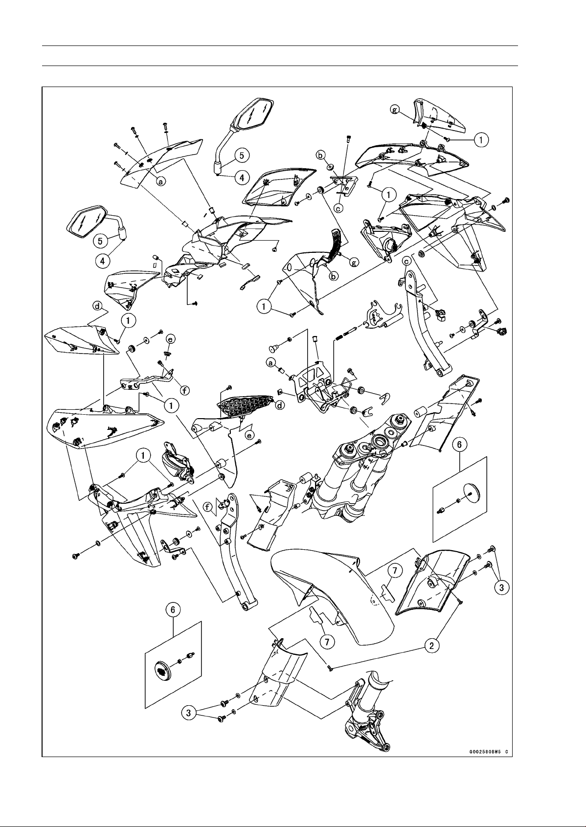
15-4 FRAME
Exploded View
ZR1000DB ∼/EB ∼

FRAME 15-5
Exploded View
Torque
No. Fastener
N·m
kgf·m ft·lb
Remarks
1
Center Fairing Assembly Screws
1.2 0.12 11 in·lb
2 Front Fender Assembly Screws 1.2 0.12 11 in·lb
3 Front Fender Mounting Bolts 3.9 0.40 35 in·lb
4
Rear View Mirror (Lower Hexagonal Area)
30 3.1 22
5 Rear View Mirror (Upper Hexagonal Area) 18 1.8 13
6. Reflectors (US, CA, and CAL Models)
7. Pads (Refer to Front Fender Installation.)
ZR1000DB/EB: Longer Pads
ZR1000DC ∼/EC ∼: Shorter Pads
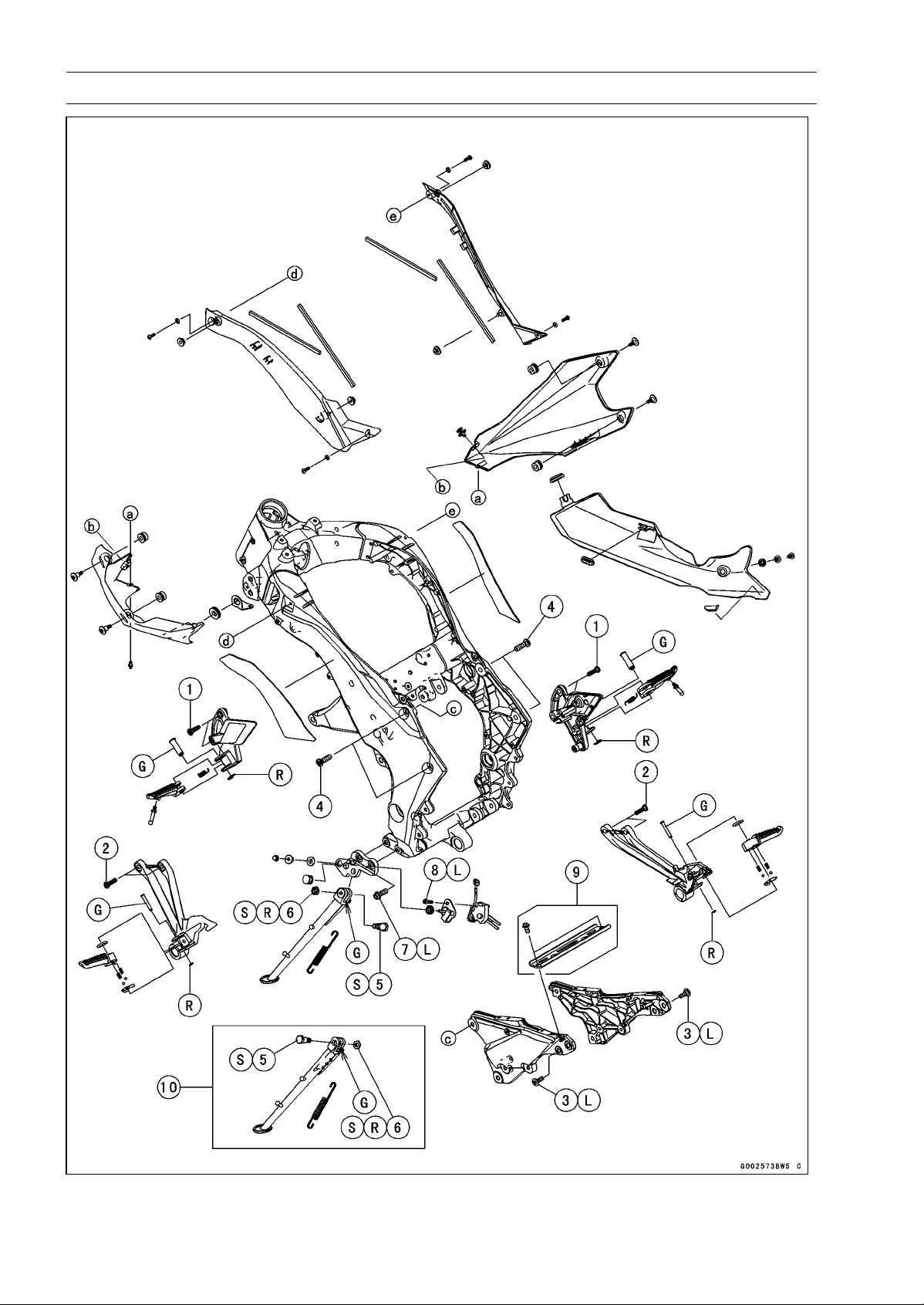
15-6 FRAME
Exploded View

FRAME 15-7
Exploded View
Torque
No. Fastener
N·m
kgf·m ft·lb
Remarks
1 Front Footpeg Bracket Bolts 25 2.5 18
2 Rear Footpeg Bracket Bolts 25 2.5 18
3 Rear Frame Bolts 25 2.5 18 L
4 Rear Frame Bracket Bolts 44 4.5 32
5 Sidestand Bolt 44 4.5 32 S
6
Sidestand Locknut
29 3.0 21
R, S
7
Sidestand Bracket Bolts
49 5.0 36 L
8 Sidestand Switch Bolt 8.8 0.90 78 in·lb L
9. ∼ ZR1000DB/EB
10. ∼ ZR1000DC/EC
G: Apply grease.
L: Apply a non-permanent locking agent.
R: Replacement Parts
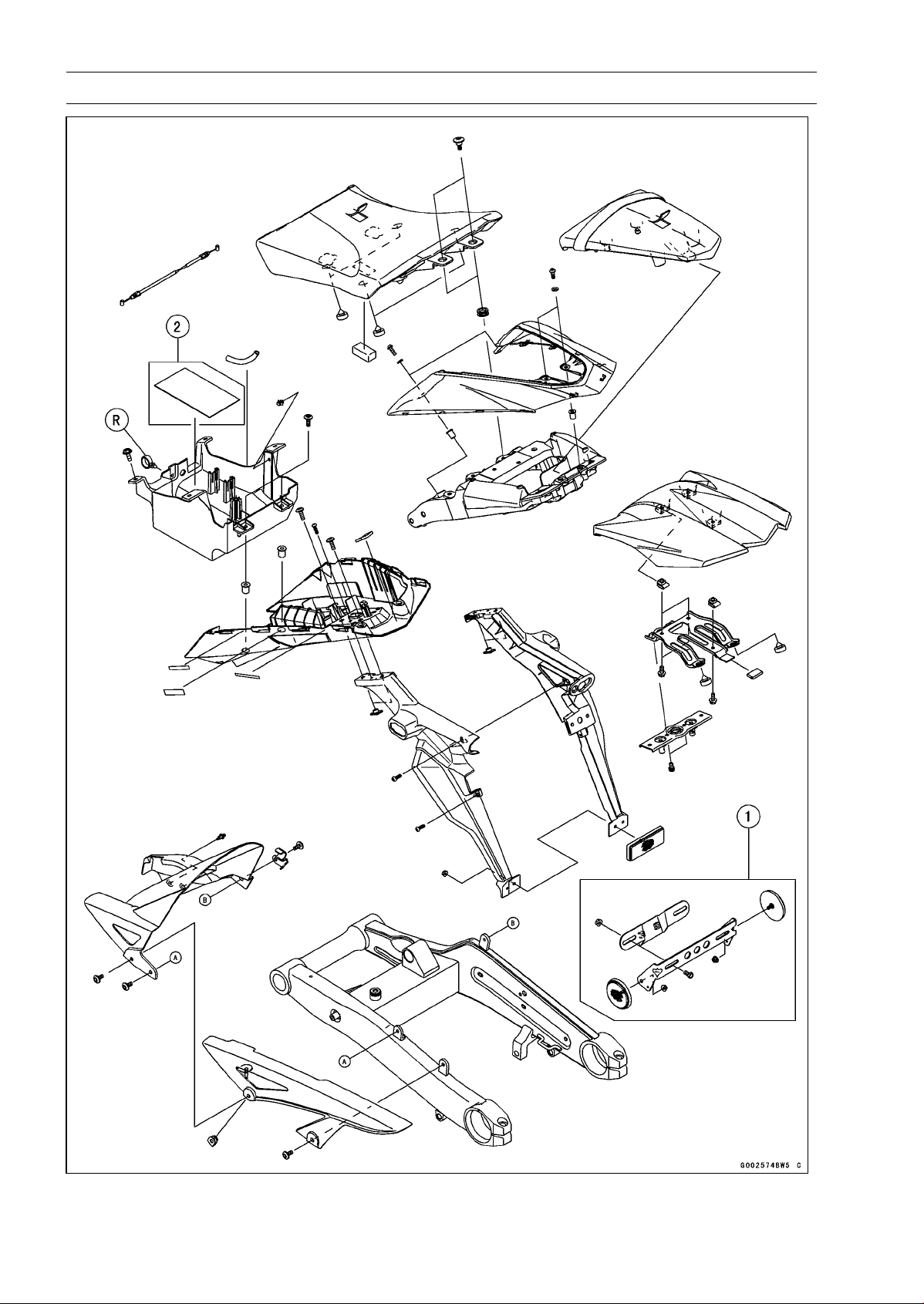
15-8 FRAME
Exploded View
1. Reflectors (US, CA, and CAL Models)
2. ZR1000DC/EC Late Models ∼
R: Replacement Parts
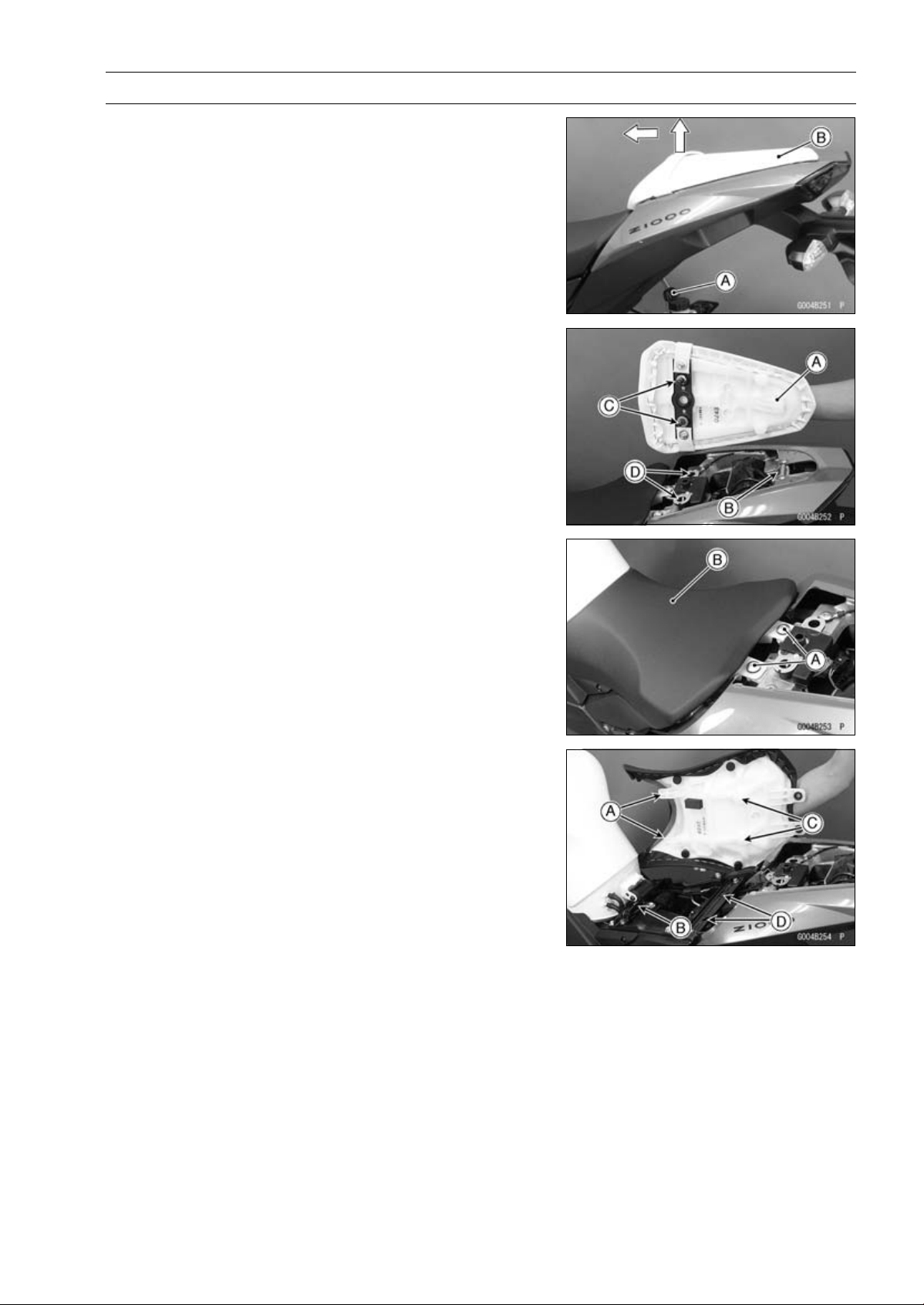
FRAME 15-9
Seats
Rear Seat Removal
•
Insert the ignition switch key [A] into the seat lock, turning
the key clockwise, pulling the front part of the seat [B] up,
and pull the seat forward.
Rear Seat Installation
•
Insert the rear seat hook [A] under the rear frame [B].
•
Insert the seat hooks [C] into the latch holes [D].
•
Push down the front part of the seat until the lock clicks.
Front Seat Removal
•
Remove the rear seat (see Rear Seat Removal).
•
Remove the front seat bolts [A], and then remove the front
seat [B] by pulling the rear of it up and backward.
Front Seat Installation
•
Insert the front seat hooks [A] under the brace of the fuel
tank bracket [B].
•
Insert the seat hooks [C] into the latch holes [D].
•
Push down the rear part of the seat until the lock clicks.
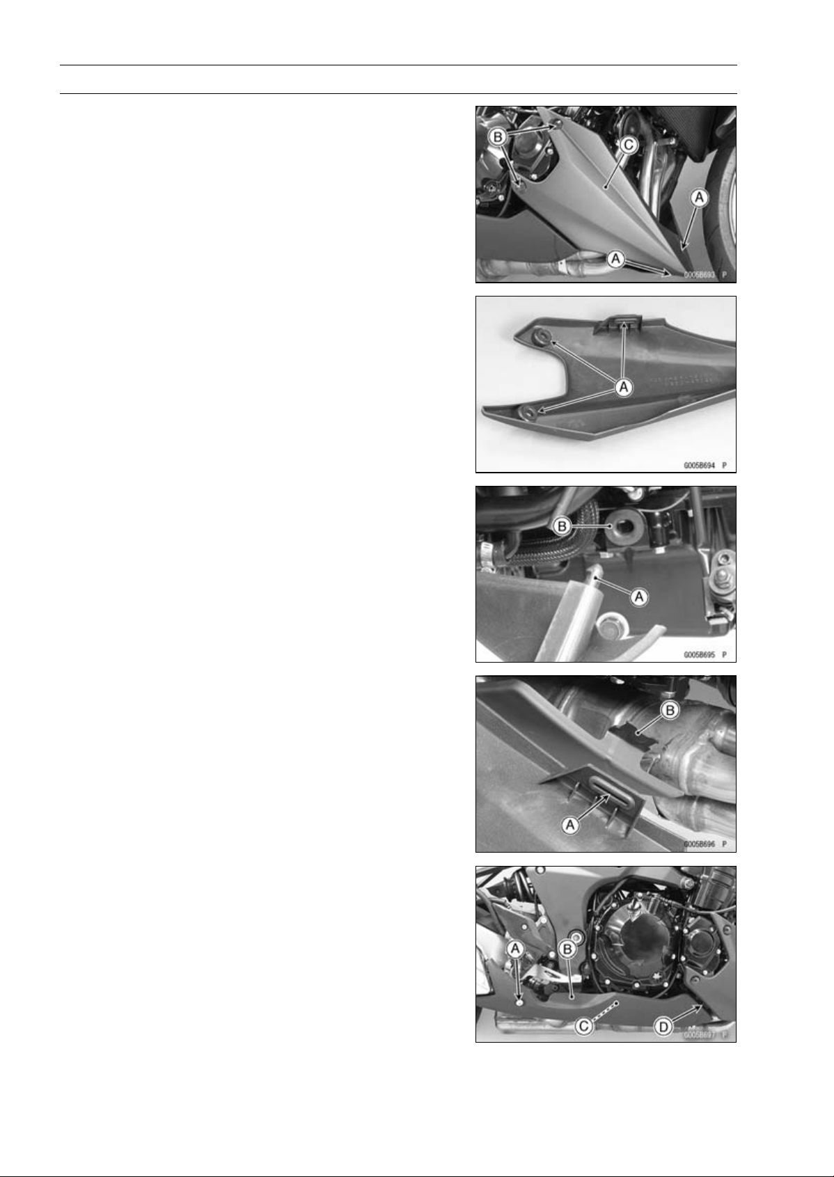
15-10 FRAME
Fairings
Lower Fairing Removal
•
Remove:
Quick Rivets [A]
Bolts [B]
•
Pull out the lower fairing [C].
Lower Fairing Installation
•
Be sure to install the dampers [A].
•
For left lower fairing installation, insert the stopper [A] into
the damper [B] on the oil pan bracket.
•
For right lower fairing installation, insert the damper [A]
into the projection [B] on the rear lower fairing.
Rear Lower Fairing Removal
•
Remove the bolt [A] and collar.
•
Pull out the rear lower fairing [B] outward to clear the pro-
jection [C].
•
Pull out the rear lower fairing rearward to clear the projec-
tion [D].
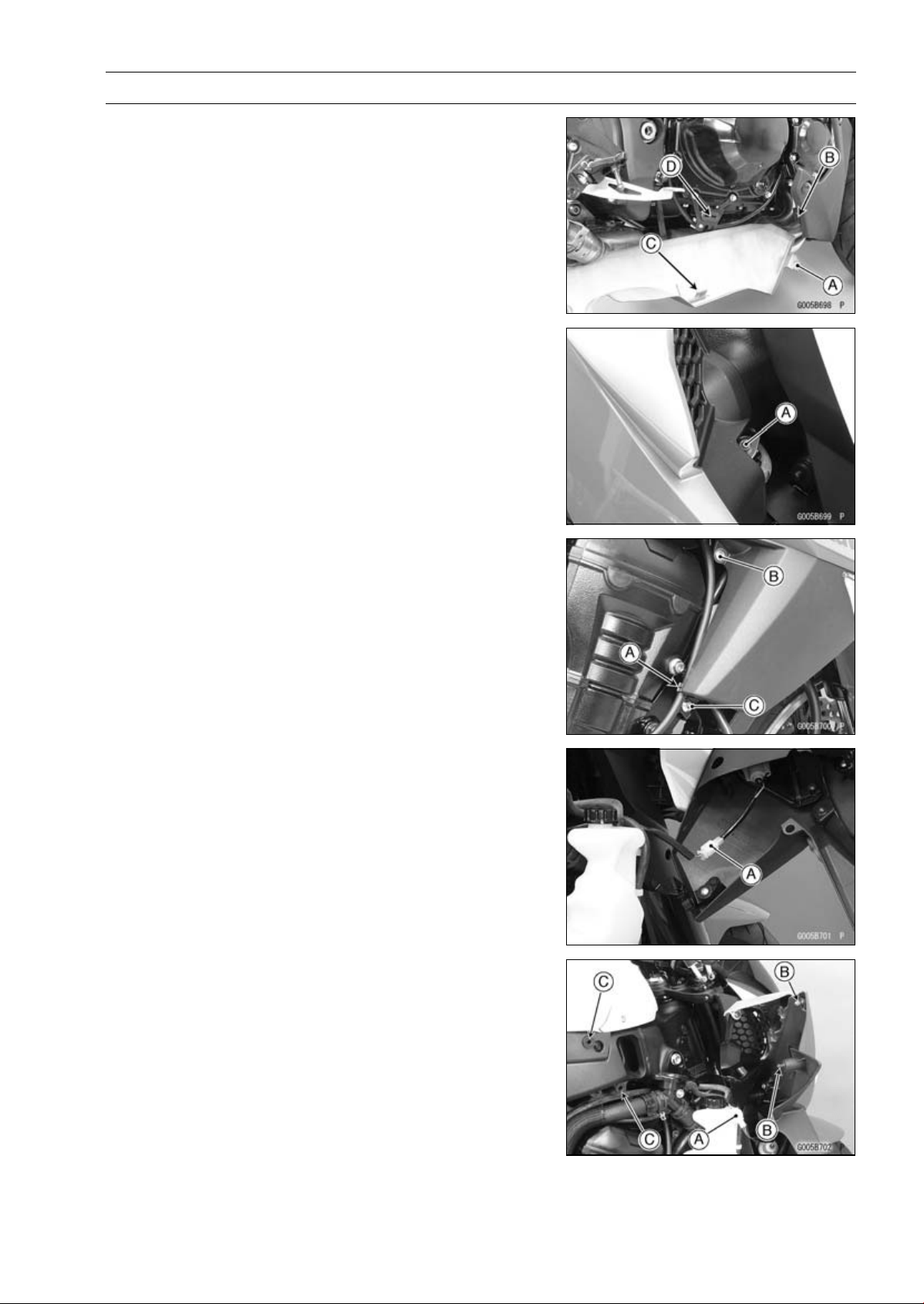
FRAME 15-11
Fairings
Rear Lower Fairing Installation
•
Insert the projection [A] into the damper [B] on the right
lower fairing.
•
Insert the projection [C] into the damper [D].
Center Fairing Removal
•
Remove:
Bolt [A]
•
Clear the clutch cable from the holder [A].
•
Remove:
Bolt [B] and Washer
Bolt [C]
•
Pull out the center fairing outward.
•
Disconnect the turn signal lead connector [A].
Center Fairing Installation
•
Connect the turn signal lead connector [A].
•
Insert the stoppers [B] into the dampers [C].
•
Tighten the bolts.
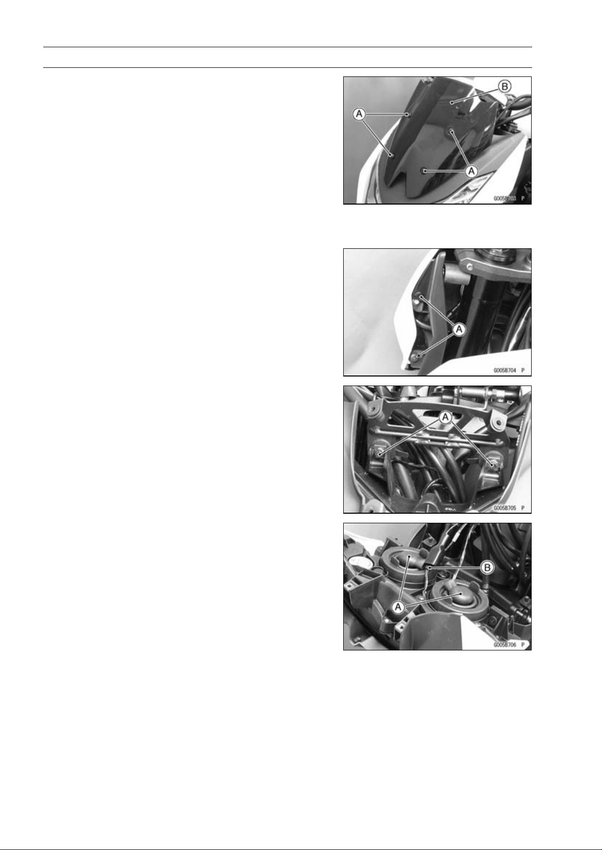
15-12 FRAME
Fairings
Windshield Removal
•
Remove:
Bolts [A] with Washers
Windshield [B]
Windshield Installation
•
Installation is the reverse of removal.
Upper Fairing Removal
•
Remove:
Windshield (see Windshield Removal)
Quick Rivets [A] (Both Sides)
•
Remove:
Bolts [A]
•
Pull out the upper fairing upward.
•
Disconnect:
Headlight Lead Connectors [A]
City Light Lead Connector [B]
•
Remove the upper fairing with the headlight.
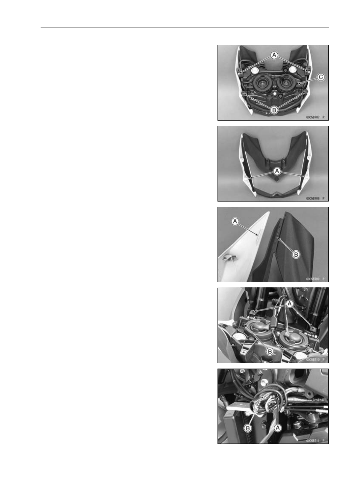
FRAME 15-13
Fairings
Upper Fairing Disassembly
•
Remove:
Upper Fairing (see Upper Fairing Removal)
Bolts [A]
QuickRivets[B]
Headlight [C]
•
Remove:
Bolts [A]
•
Separate the upper fairing.
Upper Fairing Assembly
•
Fit the projection [A] into the slit [B].
Upper Fairing Installation
•
Connect:
City Light Lead Connector
Headlight Lead Connectors
•
Fit the projections [A] on the upper fairing bracket into the
holes [B] of the headlight.
•
Tighten the mounting bolts.
Upper Fairing Bracket Removal
•
Disconnect:
Right Switch Housing Lead Connector [A]
Left Switch Housing Lead Connector [B]

15-14 FRAME
Fairings
•
Remove:
Upper Fairing (see Upper Fairing Removal)
Throttle Cables [A]
Meter Unit Lead [B]
Right Switch Housing Lead [C]
Left Switch Housing Lead [D]
Bolts [E]
Upper Fairing Bracket [F]
Upper Fairing Bracket Installation
•
Installation is the reverse of removal.
○
Run the cables and leads correctly (see Cable, Wire, and
Hose Routing section in the Appendix chapter).
Inner Fairing Removal
•
Remove:
Center Fairings (see Center Fairing Removal)
Screws [A]
Inner Fairing [B]
Inner Fairing Installation
•
Installation is the reverse of removal.
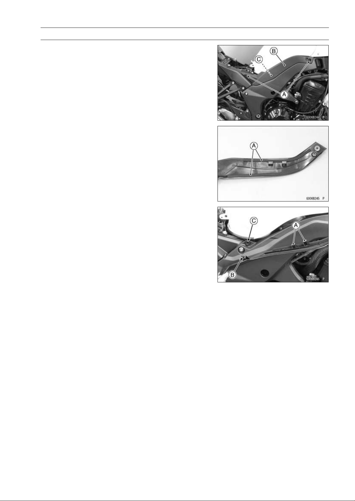
FRAME 15-15
Side Covers
Side Cover Removal
•
Remove:
Seat (see Seat Removal)
Bolts [A]
•
Pull the side cover [B] outward to clear the stopper [C].
Side Cover Installation
•
Be sure to install the pads [A].
•
Hang the hooks [A] to the frame.
•
Insert the projections [B] into the holes [C].
•
Install the bolts.
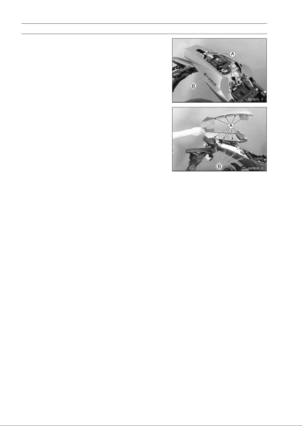
15-16 FRAME
Seat Covers
Seat Cover Removal
•
Remove:
Seats (see Rear/Front Seat Removal)
Bolts [A] and Washers
Seat Cover [B]
○
Pull out the seat cover rearward to clear the craws.
Seat Cover Installation
•
Fit the craws [A] into the slits [B] on the rear fender.
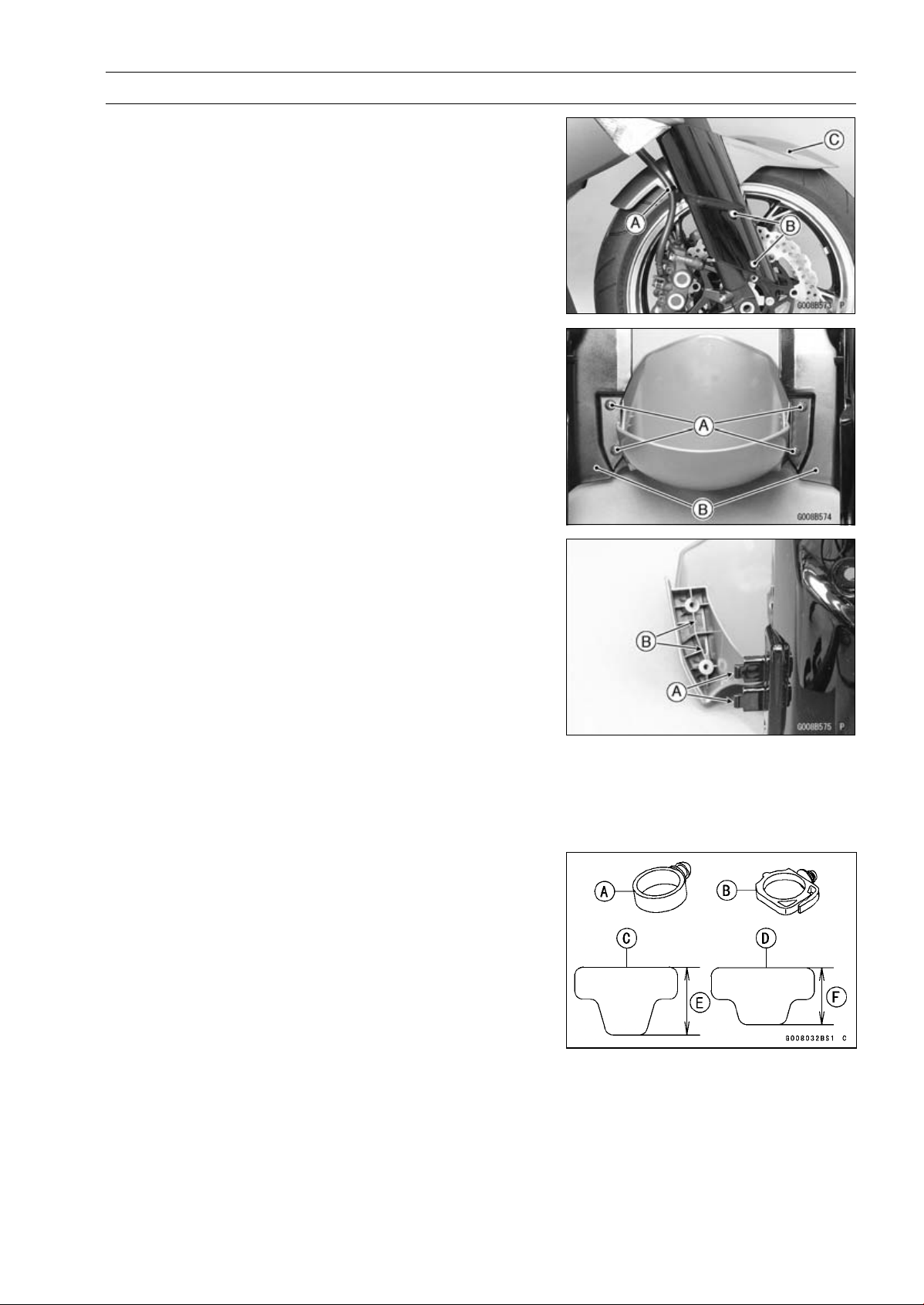
FRAME 15-17
Fenders
Front Fender Removal
•
Remove:
Brake Hose Clamps [A] (Both Sides)
Front Fender Mounting Bolts [B] with Washers (Both
Sides)
Front Fender Assy [C]
•
Remove the front fender assembly screws [A].
•
Separate the front fender side covers [B] and front fender.
Front Fender Installation
•
Install the front fender side covers to the front fender.
○
Insert the hooks [A] of the front fender cover into the slots
[B] of the front fender.
•
Tighten:
Torque - Front Fender Assembly Screws: 1.2 N·m (0.12
kgf·m, 11 in·lb)
•
Install the front fender assy to the front fork.
•
Tighten:
Torque - Front Fender Mounting Bolts: 3.9 N·m (0.40 kgf·m,
35 in·lb)
•
For ZR1000DA ∼ DB/EA ∼ EB, replace the clamps with
new ones.
NOTE
○
When replacing the clamps (P/No. 92037-1827) [A]
with the clamps (P/No. 92137-0868) [B], the longer
pads (P/No. 39156-0711) [C] must be replaced with the
shorter pads (P/No. 93156-0766) [D].
[E]38mm(1.5in.)
[F]32mm(1.3in.)
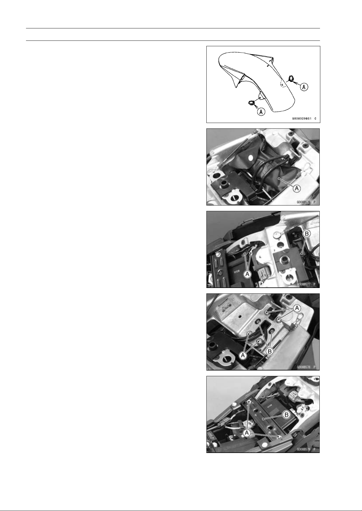
15-18 FRAME
Fenders
•
Install the brake hose clamps to the front fender holes.
•
For ZR1000DC ∼/EC ∼, face the lock [A] of the brake hose
clamp backward.
Flap and Rear Fender Removal
•
Remove:
Seat Covers (see Seat Cover Removal)
Owner’s Tool [A] and Pad
•
Disconnect:
Turn Signal Lead Connectors [A]
Licence Plate Light Lead Connector [B]
•
Remove:
Bolts [A]
Screws [B]
•
Remove:
Bolts [A]
Seat Bracket [B]
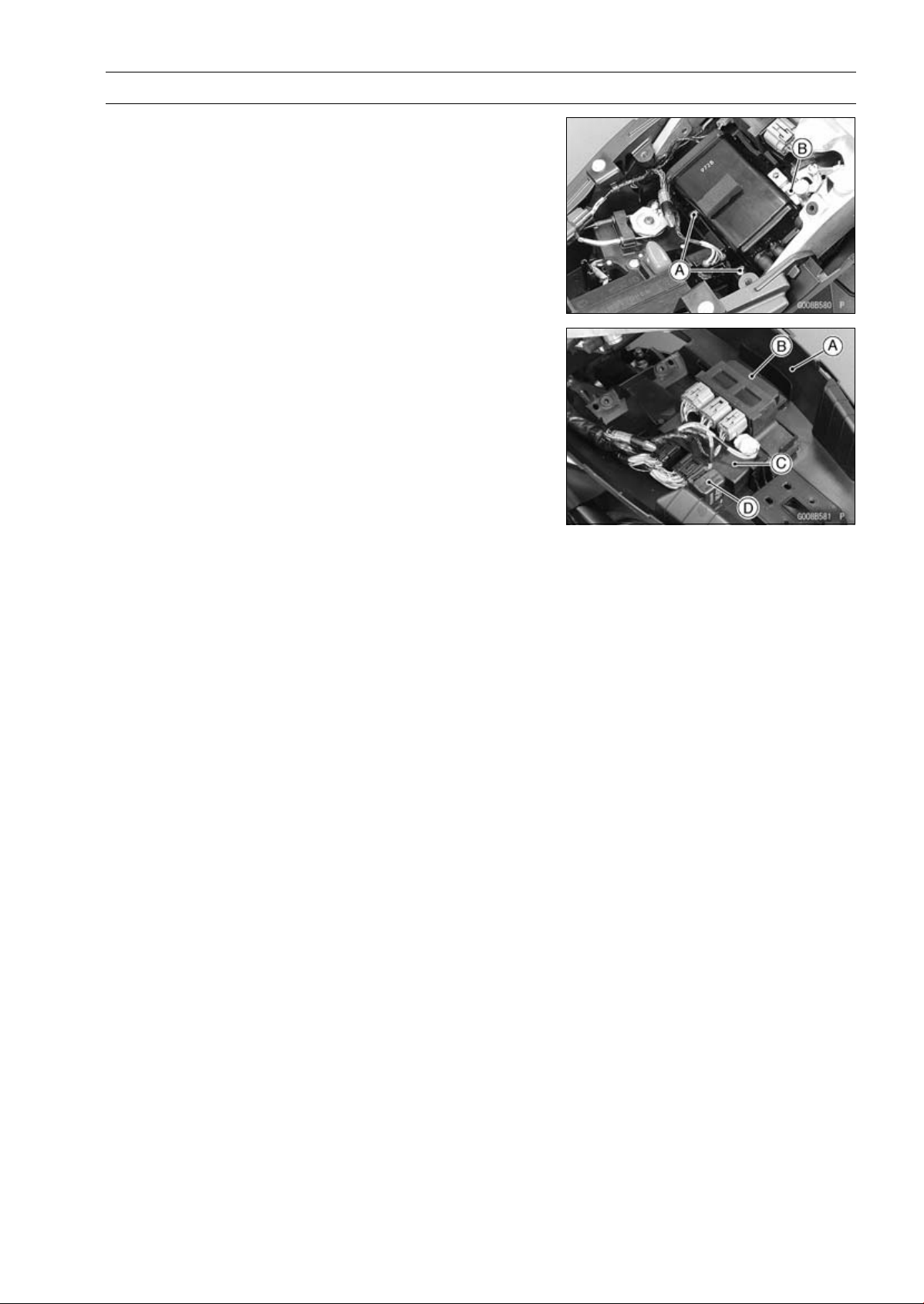
FRAME 15-19
Fenders
•
Remove:
Bolts [A]
Screw [B]
•
Push the rear fender [A] downward.
•
Remove:
Relay Box [B]
ECU [C]
Turn Signal Relay [D]
•
Remove the rear fender rearward.
Flap and Rear Fender Installation
•
Installation is the reverse of removal.
•
Install the removed parts (see appropriate chapters).
•
Run the cables, leads, harness and hose correctly (see
Cable, Wire, and Hose Routing section in the Appendix
chapter).
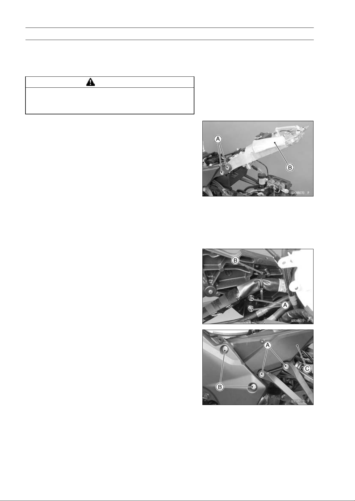
15-20 FRAME
Frame
Frame Inspection
•
Visually inspect the frame for cracks, dents, bending, or
warp.
○
If there is any damage to the frame, replace it.
WARNING
A repaired frame may fail in use, possibly causing
an accident resulting in injury or death. If the frame
is bent, dented, cracked, or warped, replace it.
Rear Frame Removal
•
Remove:
Rear Fender (see Rear Fender Removal)
Rear Frame Bolts [A] (Both Sides)
Rear Frame [B]
Rear Frame Installation
•
Apply a non-parmanent locking agent to the thread of the
rear frame bolts.
•
Tighten:
Torque - Rear Fender Bolts: 25 N·m (2.5 kgf·m, 18 ft·lb)
Rear Frame Bracket Removal
•
Remove:
Side Cover (see Side Cover Removal)
Battery Case (see Battery Case Removal)
Rear Frame (see Rear Frame Removal)
Bolts [A]
Clamps [B] (Both Sides)
•
Remove:
Rear Footpeg Bracket Bolts [A] (Both Sides)
Rear Frame Bracket Bolts [B] (Both Sides)
Rear Frame Bracket [C]
Rear Frame Bracket Installation
•
Tighten:
Torque - Rear Frame Bracket Bolts: 44 N·m (4.5 kgf·m, 32
ft·lb)
Rear Footpeg Bracket Bolt: 25 N·m (2.5 kgf·m, 18
ft·lb)

FRAME 15-21
Battery Case
Battery Case Removal
•
Remove:
Battery (see Battery Removal in the Electrical System
chapter)
Exhaust Butterfly Valve Actuator [A] (see Exhaust But-
terfly Valve Actuator Removal in the Fuel System (DFI)
chapter)
Seat Bracket
•
Disconnect:
Vehicle-down Sensor Connector [B]
Starter Relay Connector [C]
•
Remove:
Fuse Box [D]
ABS Fuse Box [E]
Bolts [F]
Clamp [G]
•
Pull the battery case rearward.
•
Remove the clamp [A] (regulator/rectifier lead) from the
battery case.
•
Remove the batter case.
Battery Case Installation
•
Installation is the reverse of removal.
•
Install the removed parts (see appropriate chapters).
•
Replace the regulator/rectifier lead clamp with a new one.
•
Run the cables, leads, harness and hose correctly (see
Cable, Wire, and Hose Routing section in the Appendix
chapter).
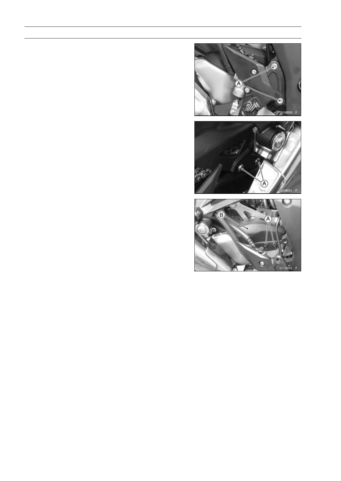
15-22 FRAME
Guard
Mud Guard Removal
•
Remove:
Rear Lower Fairing (see Rear Lower Fairing Removal)
Right Front Footpeg Bracket Bolts [A]
•
Remove:
Bolts [A]
•
Remove:
Quick Rivets [A]
Mud Guard [B]
Mud Guard Installation
•
Installation is the reverse of removal. note the following.
Torque - Front Footpeg Bracket Bolts: 25 N·m (2.5 kgf·m,
18 ft·lb)
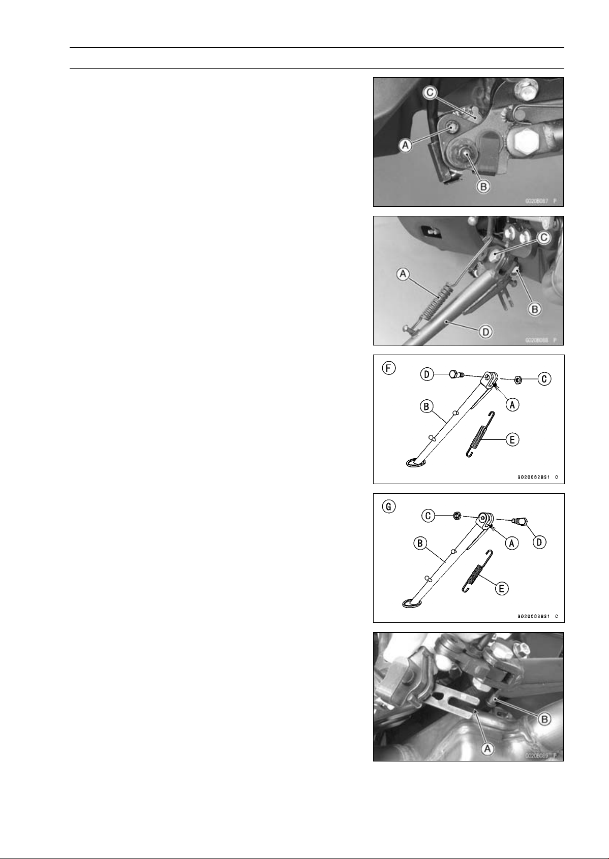
FRAME 15-23
Sidestand
Sidestand Removal
•
Raise the rear wheel off the ground with the stand.
•
Remove:
Sidestand Switch Bolt [A] and Nut [B]
Sidestand Switch [C]
•
Remove:
Spring [A]
Sidestand Nut [B]
Sidestand Bolt [C]
Sidestand [D]
Sidestand Installation
•
Apply grease to the sliding area [A] of the sidestand [B].
•
Replace the sidestand locknut [C] with a new one.
•
Tighten the bolt first, then tighten the locknut.
Torque - Sidestand Bolt [D]: 44 N·m (4.5 kgf·m, 32 ft·lb)
Sidestand Locknut: 29 N·m (3.0 kgf·m, 21 ft·lb)
•
Hook the spring [E] so that face the long spring end up-
ward.
○
Install the spring hook direction as shown in the figure.
∼ ZR1000DC/EC [F]
ZR1000DD/ED [G]
•
Install the sidestand switch.
○
Fit the slit [A] on the sidestand switch to the pin [B] on the
sidestand.
•
Apply a non-permanent locking agent to the thread of the
switch bolt, and tighten it.
Torque - Sidestand Switch Bolt: 8.8 N·m (0.90 kgf·m, 78
in·lb)
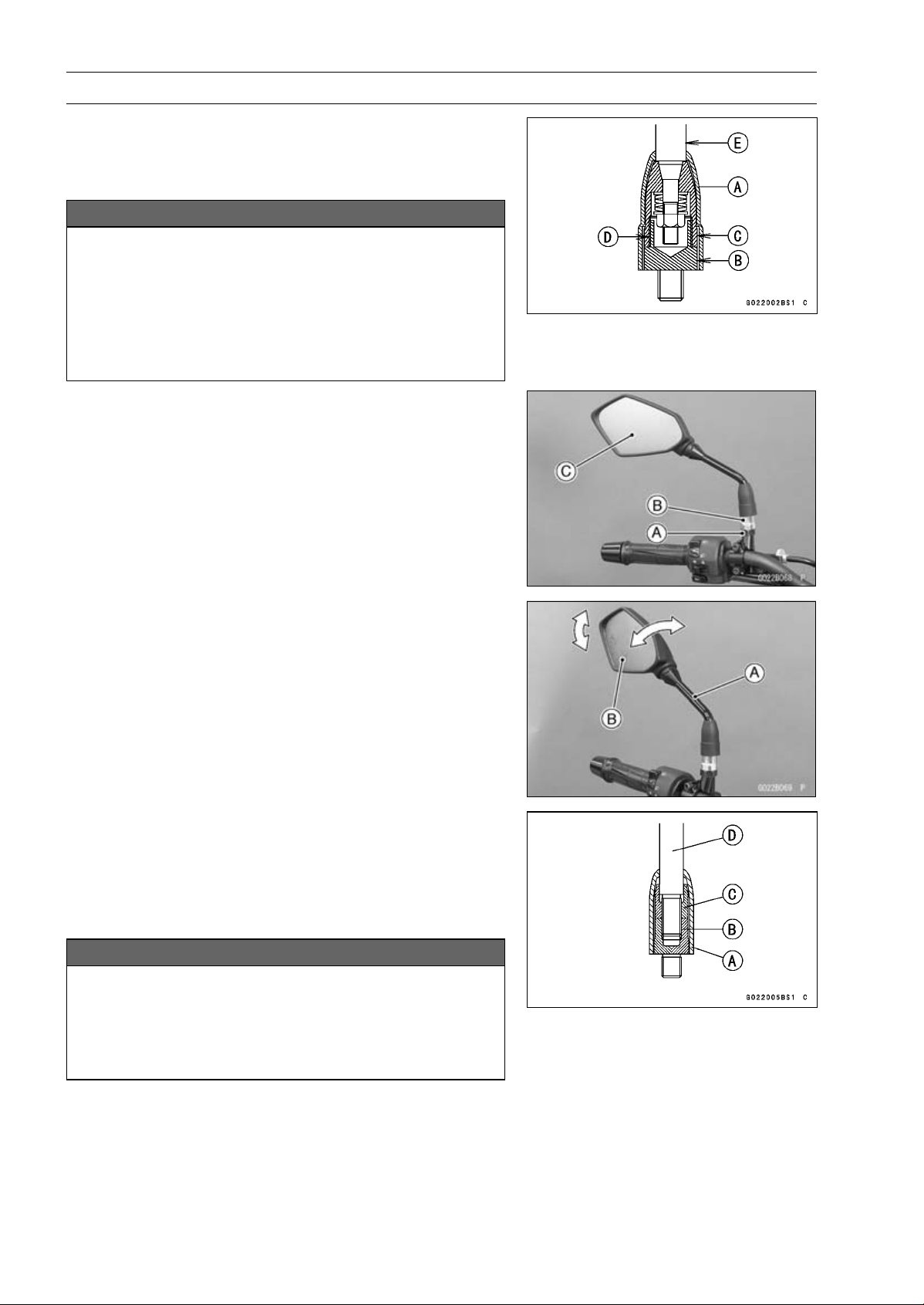
15-24 FRAME
Rear View Mirrors
Rear View Mirrors Removal (ZR1000DA/EA)
•
Slide the cover [A] upward.
•
Loosen the lower hexagonal area [B] to remove the rear
view mirror from the holder.
NOTICE
Do not force to tighten and/or loosen the upper
hexagonal area (adapter) [C] with a pair of span-
ners. Disassembly of this area is Not Available.
Non-permanent locking agent [D] is already applied
to the threads of this inner area. Forcible loosen-
ing may damage the adapter and/or the turning
mechanism of the stay [E].
Rear View Mirrors Installation (ZR1000DA/EA)
•
Screw the mounting area of the left rear view mirror into
the holder all the way, and tighten the lower hexagonal
area for tightening securely.
Lower Hexagonal Area for Tightening [A]
Upper Hexagonal Area (Adapter) [B]
Rear View Mirror (Left) [C]
•
Turn the stay [A] to assure the safe conditions of the rear
with the operator sat on the motorcycle.
•
Adjust the rear view mirror slightly with its mirror [B].
○
Installation and adjustment of the right side are common
with those of the left side. Follow the procedure specified
at the left side.
Rear View Mirrors Removal (ZR1000DB
∼
/EB
∼
)
•
Slide the dust cover [A].
•
Loosen the lower hexagonal area [B], and remove the rear
view mirror [C] from the holder.
○
The lower hexagonal area and rear view mirror are left
-hand thread.
NOTICE
Do not force to tighten and/or loosen the upper
hexagonal area (adapter) [C] with a pair of span-
ners. Disassembly of this area is Not Available.
Forcible loosening may damage the adapter and/or
the turning mechanism of the stay [D].
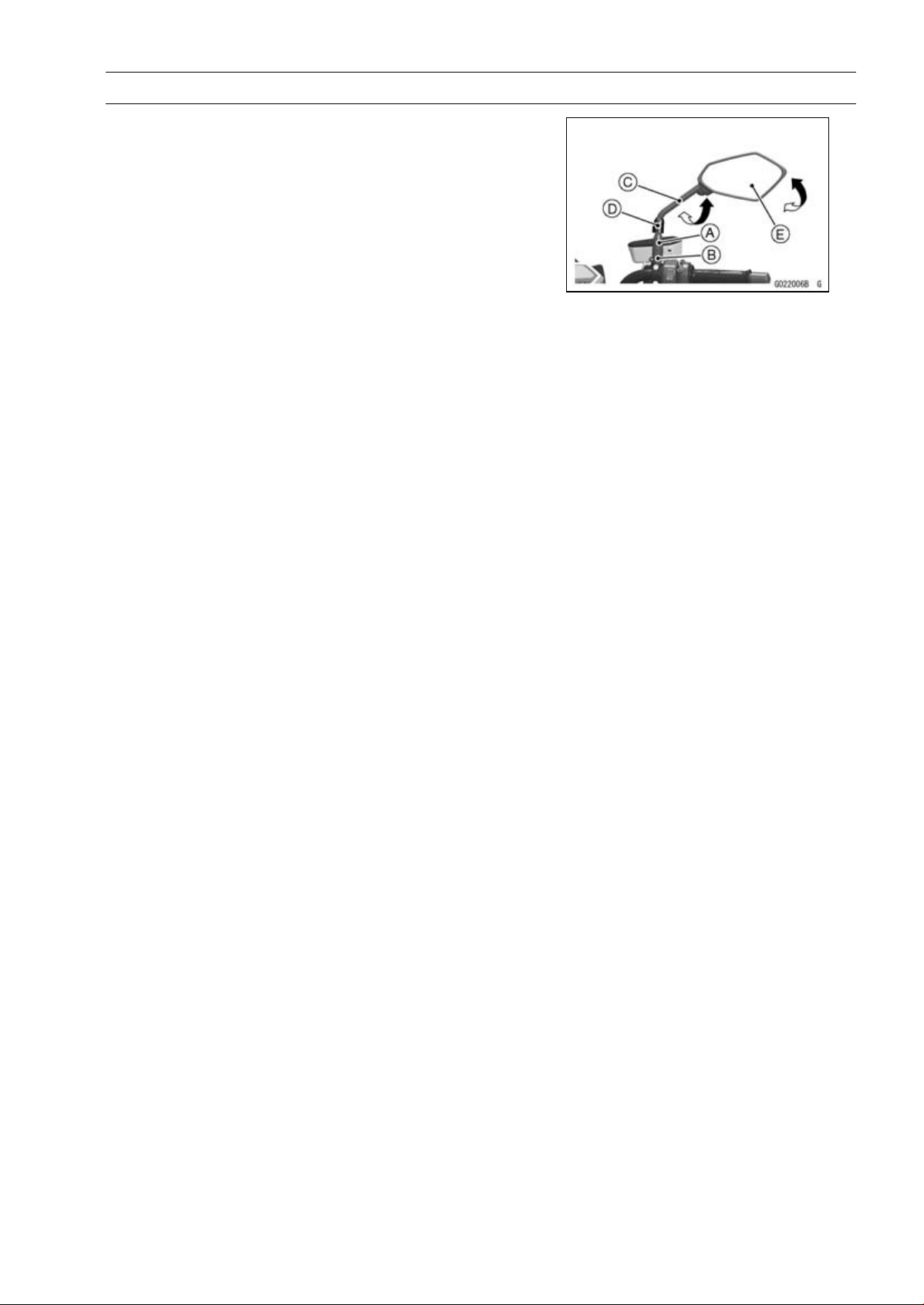
FRAME 15-25
Rear View Mirrors
Rear View Mirrors Installation (ZR1000DB
∼
/EB
∼
)
•
Tighten:
Torque - Lower Hexagonal Area [B]: 30 N·m (3.1 kgf·m, 22
ft·lb)
Upper Hexagonal Area [A]: 18 N·m (1.8 kgf·m, 13
ft·lb)
○
The lock nut and rear view mirror are left-hand thread.
○
Turn the stay [C] to assure the safe conditions of the rear
with operator sat on the motorcycle.
•
Install the dust cover [D].
•
Adjust the rear view mirror slightly with its mirror [E].
○
Installation and adjustment of the right side are common
with those of the left side. Follow the procedure specified
at the left side.


ELECTRICAL SYSTEM 16-1
16
Electrical System
Table of Contents
Exploded View........................................................................................................................ 16-4
Specifications ......................................................................................................................... 16-10
Special Tools and Sealant ...................................................................................................... 16-11
Parts Location......................................................................................................................... 16-13
Wiring Diagram (US and CA Models)..................................................................................... 16-16
Wiring Diagram (Other than US and CA Models)................................................................... 16-18
Wiring Diagram (ABS Equipped Models) ............................................................................... 16-20
Precautions............................................................................................................................. 16-22
Electrical Wiring...................................................................................................................... 16-23
Wiring Inspection .............................................................................................................. 16-23
Battery .................................................................................................................................... 16-24
Battery Removal ............................................................................................................... 16-24
Battery Installation ............................................................................................................ 16-24
Battery Activation.............................................................................................................. 16-24
Precautions ....................................................................................................................... 16-27
Interchange....................................................................................................................... 16-28
Charging Condition Inspection.......................................................................................... 16-28
Refreshing Charge............................................................................................................ 16-28
Charging System.................................................................................................................... 16-30
Alternator Cover Removal................................................................................................. 16-30
Alternator Cover Installation.............................................................................................. 16-30
Stator Coil Removal .......................................................................................................... 16-31
Stator Coil Installation....................................................................................................... 16-31
Alternator Rotor Removal ................................................................................................. 16-31
Alternator Rotor Installation .............................................................................................. 16-32
Alternator Inspection......................................................................................................... 16-33
Regulator/Rectifier Inspection........................................................................................... 16-35
Charging Voltage Inspection............................................................................................. 16-37
Ignition System....................................................................................................................... 16-39
Crankshaft Sensor Removal............................................................................................. 16-39
Crankshaft Sensor Installation.......................................................................................... 16-40
Crankshaft Sensor Inspection........................................................................................... 16-41
Crankshaft Sensor Peak Voltage Inspection..................................................................... 16-41
Timing Rotor Removal ...................................................................................................... 16-42
Timing Rotor Installation ................................................................................................... 16-42
Stick Coil Removal............................................................................................................ 16-42
Stick Coil Installation......................................................................................................... 16-42
Stick Coil Inspection.......................................................................................................... 16-43
Stick Coil Primary Peak Voltage Inspection ...................................................................... 16-43
Spark Plug Removal ......................................................................................................... 16-44
Spark Plug Installation ...................................................................................................... 16-44
Spark Plug Condition Inspection....................................................................................... 16-44
Interlock Operation Inspection .......................................................................................... 16-44
IC Igniter Inspection.......................................................................................................... 16-45
Electric Starter System........................................................................................................... 16-48
Starter Motor Removal...................................................................................................... 16-48
Starter Motor Installation................................................................................................... 16-49
Starter Motor Disassembly................................................................................................ 16-49
Starter Motor Assembly .................................................................................................... 16-50
Brush Inspection ............................................................................................................... 16-52

16-2 ELECTRICAL SYSTEM
Commutator Cleaning and Inspection............................................................................... 16-52
Armature Inspection.......................................................................................................... 16-53
Brush Lead Inspection ...................................................................................................... 16-53
Right-hand End Cover Inspection..................................................................................... 16-53
Starter Relay Inspection.................................................................................................... 16-53
Lighting System...................................................................................................................... 16-56
Headlight Beam Horizontal Adjustment ............................................................................ 16-56
Headlight Beam Vertical Adjustment................................................................................. 16-56
Headlight Bulb Replacement ............................................................................................ 16-56
Headlight Removal/Installation ......................................................................................... 16-57
City Light Bulb Replacement............................................................................................. 16-58
Tail/Brake Light (LED) Removal........................................................................................ 16-58
Tail/Brake Light (LED) Installation..................................................................................... 16-58
License Plate Light Bulb Replacement ............................................................................. 16-59
Turn Signal Light Bulb Replacement ................................................................................ 16-61
Turn Signal Relay Inspection ............................................................................................ 16-62
Air Switching Valve ................................................................................................................. 16-65
Air Switching Valve Operation Test ................................................................................... 16-65
Air Switching Valve Unit Test ............................................................................................ 16-65
Radiator Fan System.............................................................................................................. 16-67
Fan Motor Inspection ........................................................................................................ 16-67
Meter, Gauge, Indicator Unit................................................................................................... 16-69
Meter Unit Removal/Installation ........................................................................................ 16-69
Meter Unit Disassembly.................................................................................................... 16-69
Meter Unit Assembly......................................................................................................... 16-70
Meter Unit Inspection........................................................................................................ 16-70
Immobilizer System (Equipped Models), ZR1000DA/EA ....................................................... 16-79
Operational Cautions ........................................................................................................ 16-79
Key Registration................................................................................................................ 16-79
Immobilizer System Parts Replacement........................................................................... 16-95
Immobilizer System Inspection ......................................................................................... 16-97
Immobilizer System (Equipped Models), ZR1000DB ∼/EB ∼ ................................................. 16-98
Operational Cautions ........................................................................................................ 16-98
Key Registration................................................................................................................ 16-98
Immobilizer System Parts Replacement........................................................................... 16-116
Immobilizer System Inspection ......................................................................................... 16-118
Immobilizer System (Equipped Models)................................................................................. 16-119
Switches and Sensors............................................................................................................ 16-120
Brake Light Timing Inspection........................................................................................... 16-120
Brake Light Timing Adjustment ......................................................................................... 16-120
Switch Inspection.............................................................................................................. 16-120
Water Temperature Sensor Inspection ............................................................................. 16-121
Speed Sensor Removal.................................................................................................... 16-121
Speed Sensor Installation................................................................................................. 16-122
Speed Sensor Inspection.................................................................................................. 16-122
Oxygen Sensor Removal (Equipped Models)................................................................... 16-122
Oxygen Sensor Installation (Equipped Models)................................................................ 16-123
Oxygen Sensor Inspection (Equipped Models)................................................................. 16-123
Fuel Level Sensor Inspection............................................................................................ 16-123
Relay Box ............................................................................................................................... 16-124
Relay Box Removal .......................................................................................................... 16-124
Relay Circuit Inspection .................................................................................................... 16-124
Diode Circuit Inspection.................................................................................................... 16-125
Fuse........................................................................................................................................ 16-127
30 A Main Fuse Removal.................................................................................................. 16-127
Fuse Box Fuse Removal................................................................................................... 16-127
15 A FI Fuse Removal ...................................................................................................... 16-127

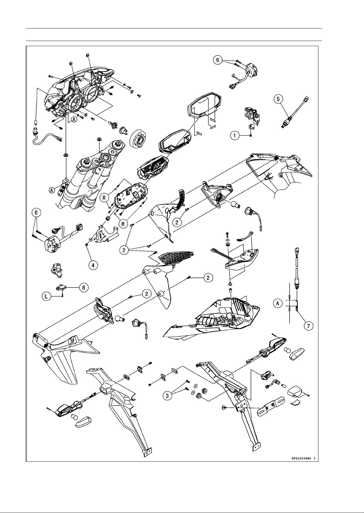
16-4 ELECTRICAL SYSTEM
Exploded View

ELECTRICAL SYSTEM 16-5
Exploded View
Torque
No. Fastener
N·m
kgf·m ft·lb
Remarks
1
Front Brake Light Switch Screw
1.2 0.12 11 in·lb
2 Front Turn Signal Light Mounting Screws 1.2 0.12 11 in·lb
3 Licence Plate Light Mounting Screws 1.2 0.12 11 in·lb
4 Meter Unit Mounting Screws 1.2 0.12 11 in·lb
5 Oxygen Sensor (Equipped Models) 44 4.5 32
6
Switch Housing Screws
3.5 0.36 31 in·lb
7. Install the rear brake light switch spring so that the longer side [A] faces upward.
8. Starter Lockout Switch
L: Apply a non-permanent locking agent.
R: Replacement Parts
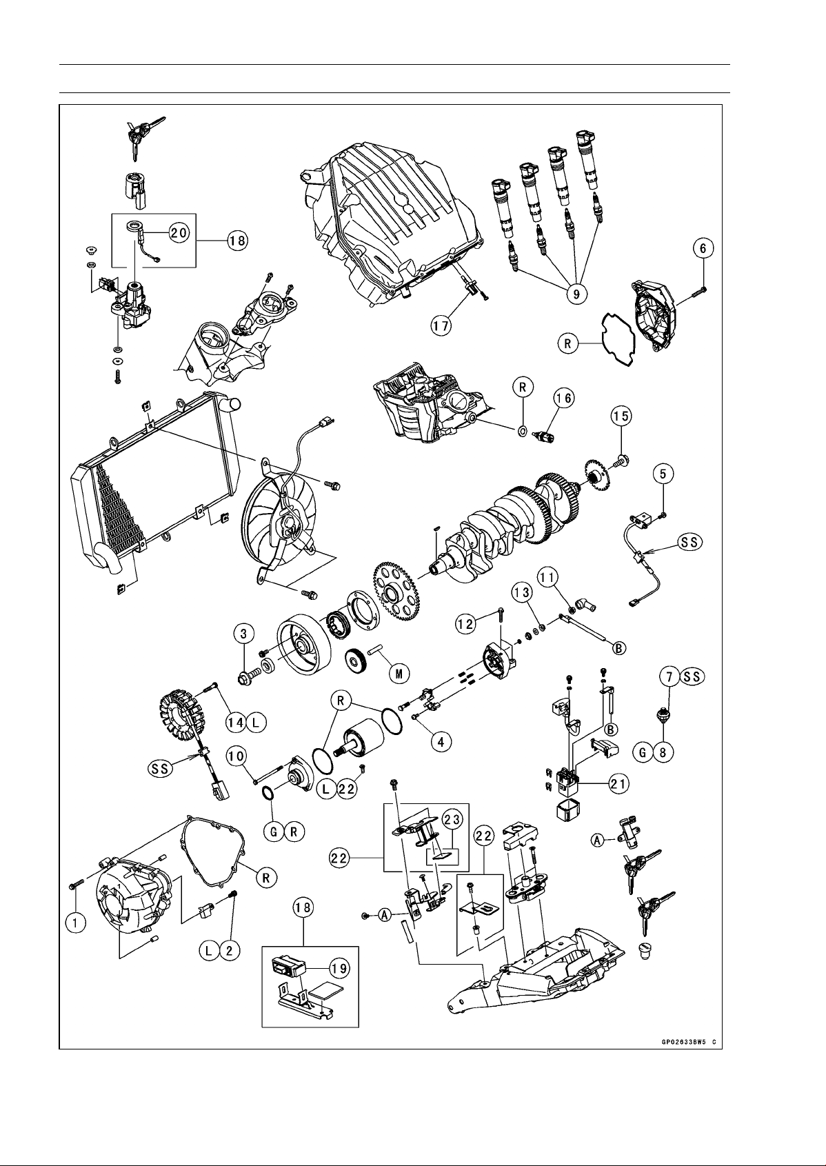
16-6 ELECTRICAL SYSTEM
Exploded View
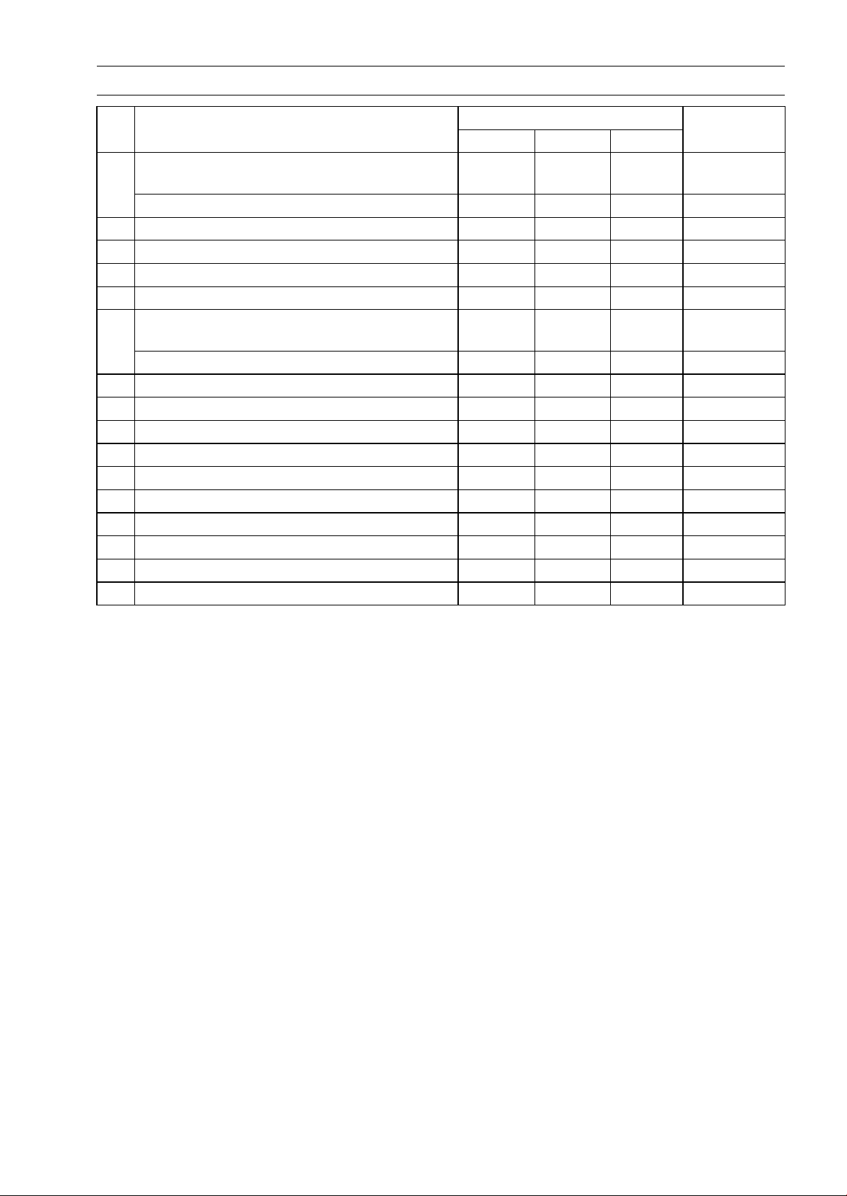
ELECTRICAL SYSTEM 16-7
Exploded View
Torque
No. Fastener
N·m
kgf·m ft·lb
Remarks
Alternator Cover Bolts (Engine No. ∼
ZRT00DE013356)
9.8 1.0 87 in·lb
1
Alternator Cover Bolts
12 1.2 106 in·ib
2 Alternator Lead Holding Plate Bolt 12 1.2 106 in·ib L
3 Alternator Rotor Bolt 155 15.8 114
4 Brush Holder Screw 3.8 0.39 34 in·ib
5 Crankshaft Sensor Bolts 5.9 0.60 52 in·lb
Crankshaft Sensor Cover Bolts (Engine No.
∼ ZRT00DE013356)
9.8 1.0 87 in·lb
6
Crankshaft Sensor Cover Bolts 12 1.2 106 in·ib
7 Oil Pressure Switch 15 1.5 11 SS
8
Oil Pressure Switch Terminal Bolt
2.0 0.20 18 in·ib
G
9
Spark Plugs
13 1.3 115 in·lb
10 Starter Motor Through Bolts 4.9 0.50 43 in·lb
11 Starter Motor Cable Terminal Nut 5.9 0.60 52 in·lb
12 Starter Motor Mounting Bolts 9.8 1.0 87 in·lb
13 Starter Motor Terminal Locknut 11 1.1 97 in·lb
14
Stator Coil Bolts
12 1.2 106 in·ib L
15 Timing Rotor Bolt 39 4.0 29
16 Water Temperature Sensor 30 3.1 22
17. Intake Air Temperature Sensor
18. Immobilizer Model
19. Immobilizer Amplifier
20. Immobilizer Antenna
21. Starter Relay
22. WVTA (FULL H) and GB WVTA (FULL H) Models
23. ZR1000DC/EC Late Models ∼
G: Apply grease.
L: Apply a non-permanent locking agent.
M: Apply molybdenum disulfide grease.
R: Replacement Parts
SS: Apply silicone sealant.
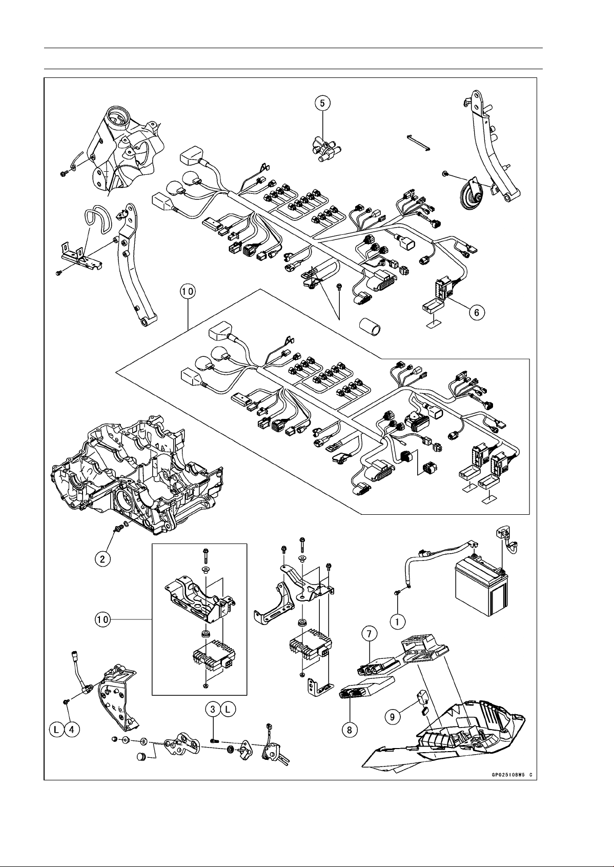
16-8 ELECTRICAL SYSTEM
Exploded View

ELECTRICAL SYSTEM 16-9
Exploded View
Torque
No. Fastener
N·m
kgf·m ft·lb
Remarks
1
Engine Ground Cable Terminal Bolt
9.8 1.0 87 in·lb
2 Neutral Switch 15 1.5 11
3 Sidestand Switch Bolt 8.8 0.90 78 in·lb L
4 Speed Sensor Mounting Bolt 6.9 0.70 61 in·lb L
5. Air Switching Valve
6. Fuel Box
7. Relay Box
8. ECU
9. Turn Signal Relay
10. ABS Equipped Models
L: Apply a non-permanent locking agent.

16-10 ELECTRICAL SYSTEM
Specifications
Item Standard
Battery
Type Sealed Battery
Model Name
YTX9-BS
Capacity
12 V 8 Ah
Voltage 12.8 V or more
Gross Weight 2.9kg(6.4lb)
Electrolyte Volume 0.40 L (24 cu in.)
Charging System
Type
Three-phase AC
Alternator Output Voltage
43 V or more at 4 000 rpm
Stator Coil Resista
nce
0.18 ∼ 0.28 Ω at 20°C (
68°F)
Charging Voltage 14.2 ∼ 15.2 V
(Regulator/Rectifier Output Voltage)
Ignition System
Crankshaft Sensor Resistance 376 ∼ 564 Ω
Crankshaft Sensor Peak Voltage 2.0 V or more
Stick Coil:
Primary Winding Resistance 1.1 ∼ 1.5 Ω
Secondary Winding Resistance 10.8 ∼ 16.2 kΩ
Primary Peak Voltage 100 V or more
Spark Plug:
Type NGK CR9EIA-9
Gap 0.8 ∼ 0.9 mm (0.031 ∼ 0.035 in.)
Electric Starter System
Starter Motor:
Brush Length 12 mm (0.47 in.) [Service limit: 6.5 mm, 0.26 in.]
Air Switching Valve
Resistance
18 ∼ 22 Ω at 20°C (68°F)
Switches and
Sensors
Rear Brake Light Switch Timing ON after about 10 mm (0.39 in.) pedal travel
Engine Oil Pressure Switch Connections When engine is stopped: ON
When engine is running: OFF
Water Temperature Sensor Resistance in the text
Fuel Level Sensor Resistance:
Full Position 9.6 ∼ 12.4 Ω
Empty Position 222 ∼ 228 Ω
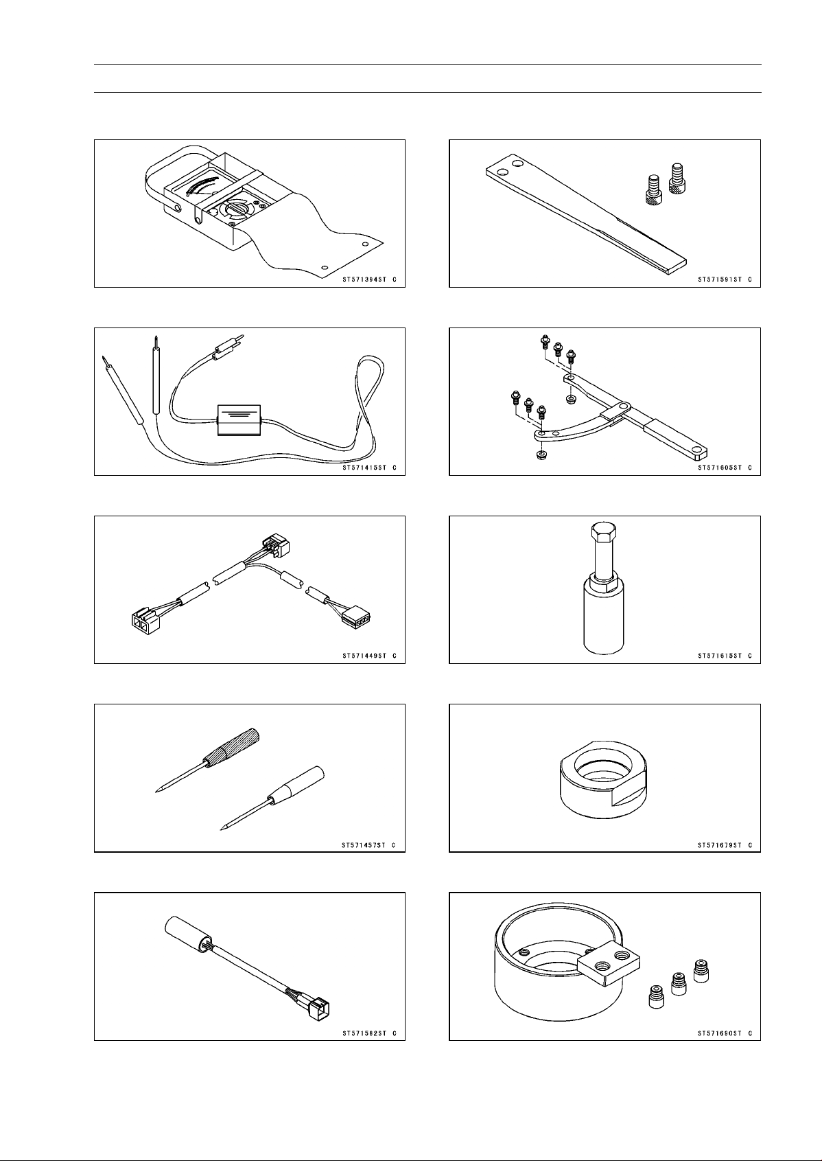
ELECTRICAL SYSTEM 16-11
Special Tools and Sealant
Hand Tester:
57001-1394
Peak Voltage Adapter:
57001-1415
Lead Wire - Peak Voltage Adapter:
57001-1449
Needle Adapter Set:
57001-1457
Key Registration Unit:
57001-1582
Grip:
57001-1591
Flywheel & Pulley Holder:
57001-1605
Flywheel Puller Assembly, M38 × 1.5/M35 × 1.5:
57001-1615
Stopper:
57001-1679
Rotor Holder:
57001-1690
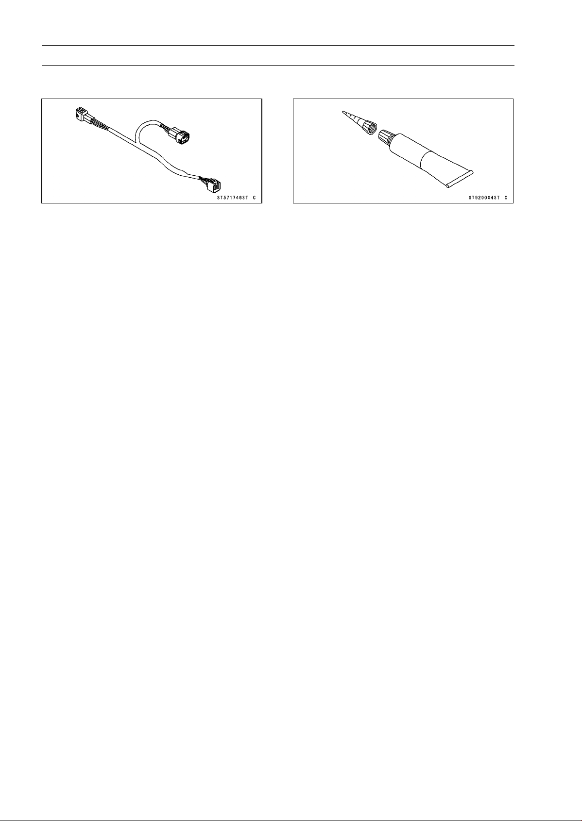
16-12 ELECTRICAL SYSTEM
Special Tools and Sealant
Key Registration Adapter:
57001-1746
Liquid Gasket, TB1211F:
92104-0004
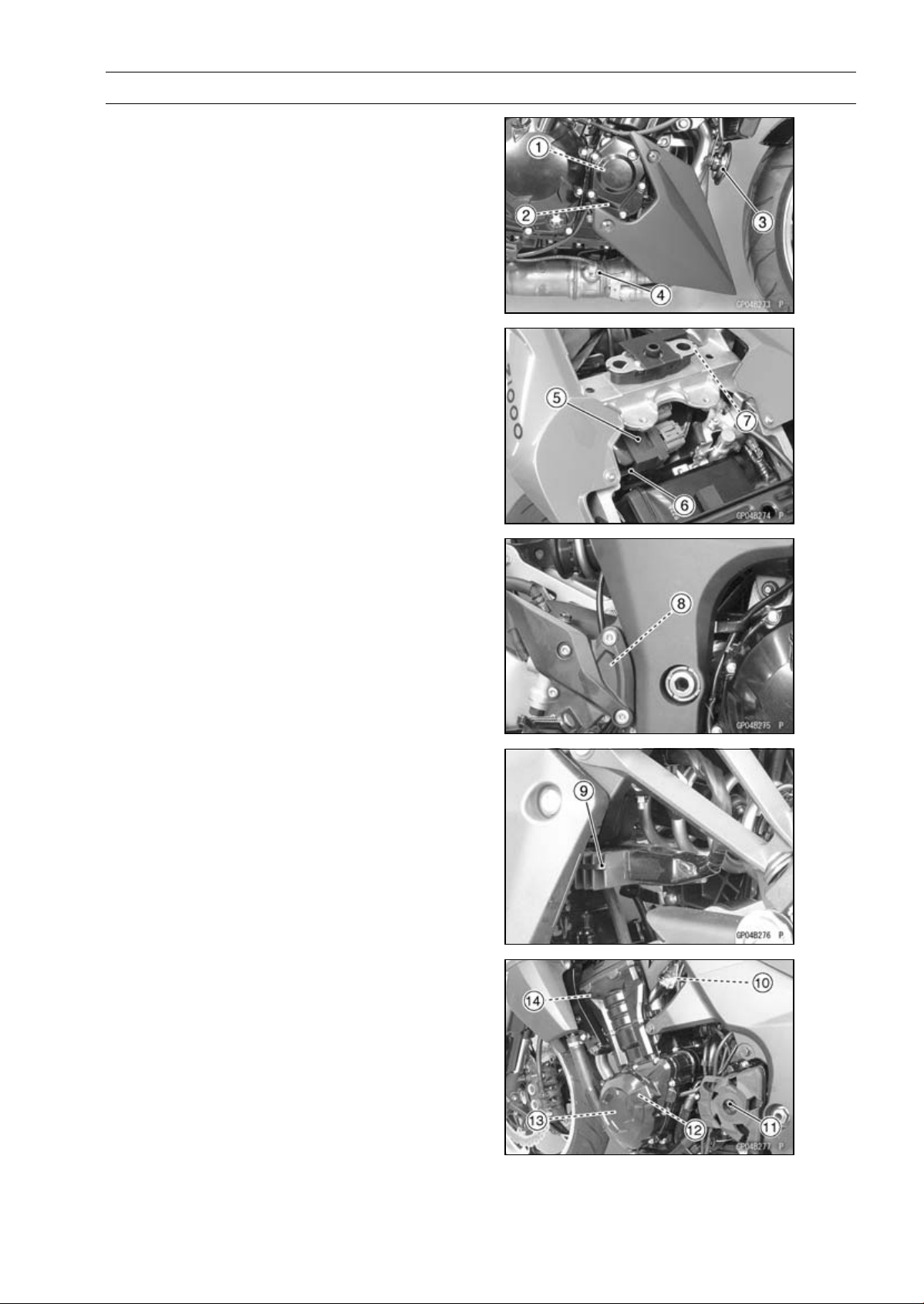
ELECTRICAL SYSTEM 16-13
Parts Location
1. Timing Rotor
2. Crankshaft Sensor
3. Horn
4. Oxygen Sensor (Equipped Models)
5. Relay Box
6. ECU
7. Turn Signal Relay
8. Rear Brake Light Switch
9. Regulator/Rectifier
10. Water Temperature Sensor
11. Speed Sensor
12. Alternator
13. Stator Coil
14. Radiator Fan Motor
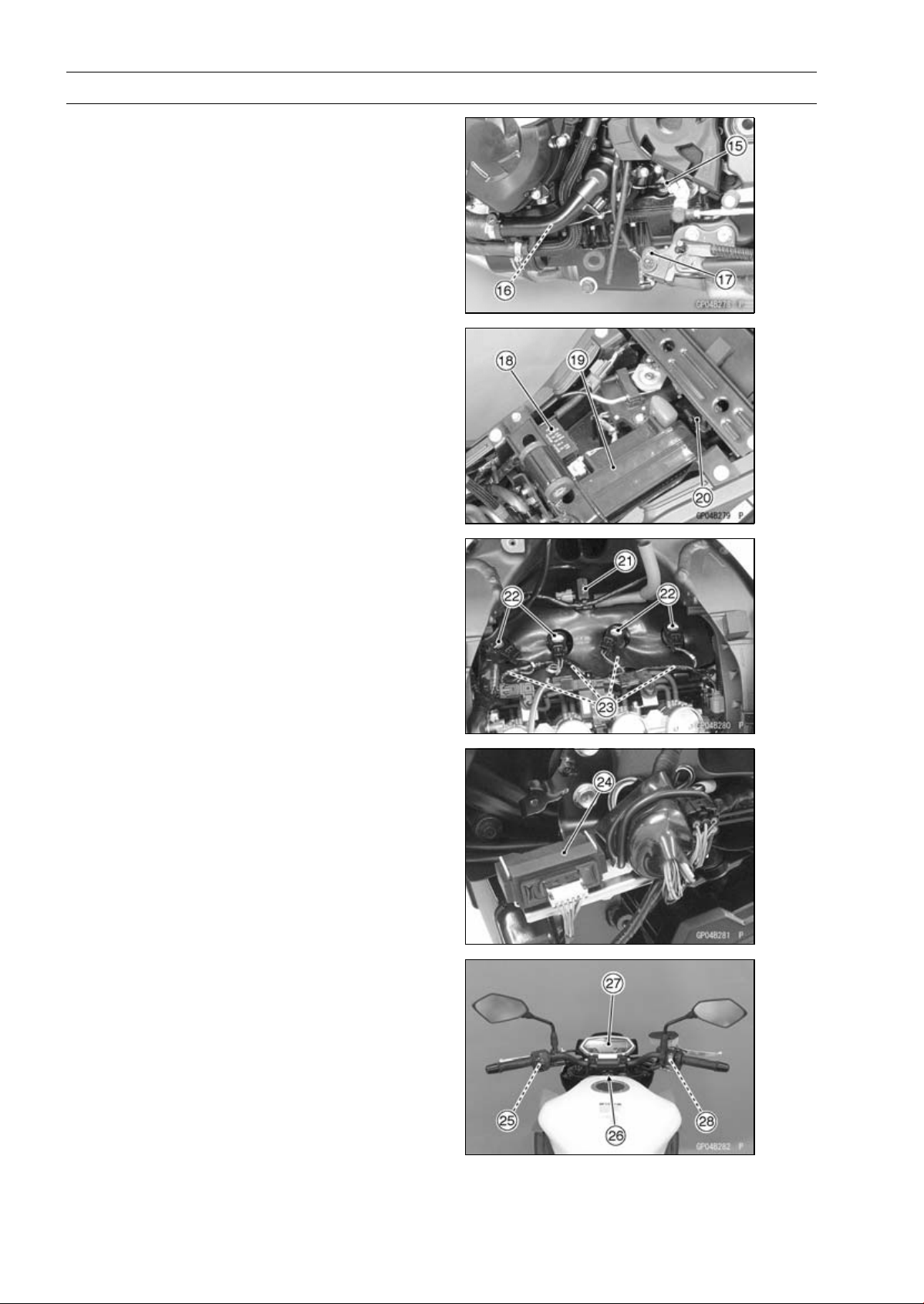
16-14 ELECTRICAL SYSTEM
Parts Location
15. Neutral Switch
16. Oil Pressure Switch
17. Sidestand Switch
18. Fuse Box
19. Battery 12 V 8 Ah
20. Starter Relay
21. Air Switching Valve
22. Stick Coils
23. Spark Plugs
24. Immobilizer Amplifier (Immobilizer Mod-
els)
25. Starter Lockout Switch
26. Ignition Switch
(Immobilizer Model: Including Immobi-
lizer Antenna)
27. Meter Unit
28. Front Brake Light Switch

ELECTRICAL SYSTEM 16-15
Parts Location
This page intentionally left blank.
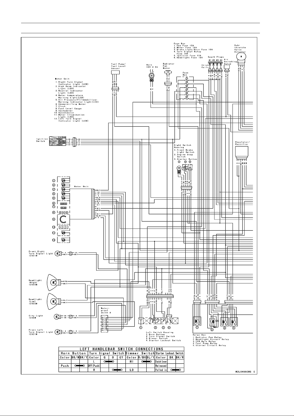
16-16 ELECTRICAL SYSTEM
Wiring Diagram (US and CA Models)
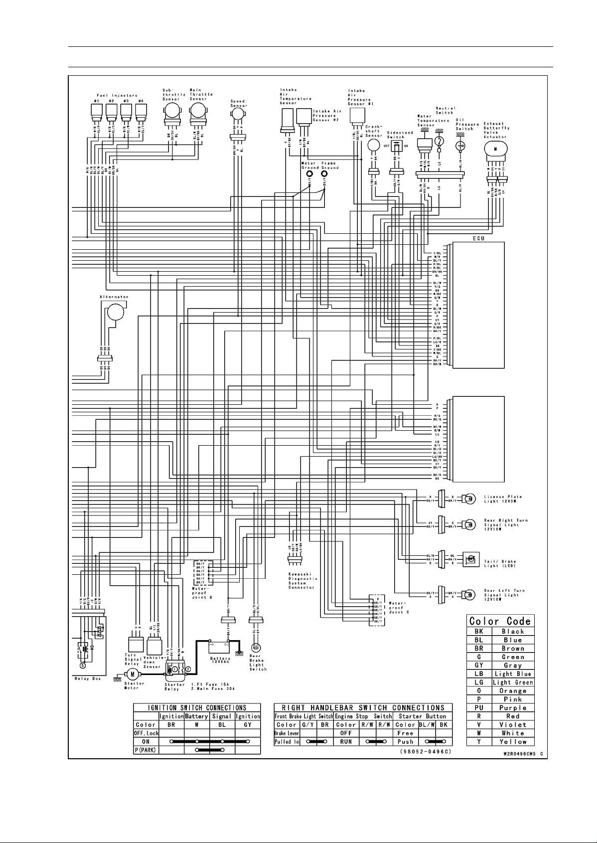
ELECTRICAL SYSTEM 16-17
Wiring Diagram (US and CA Models)
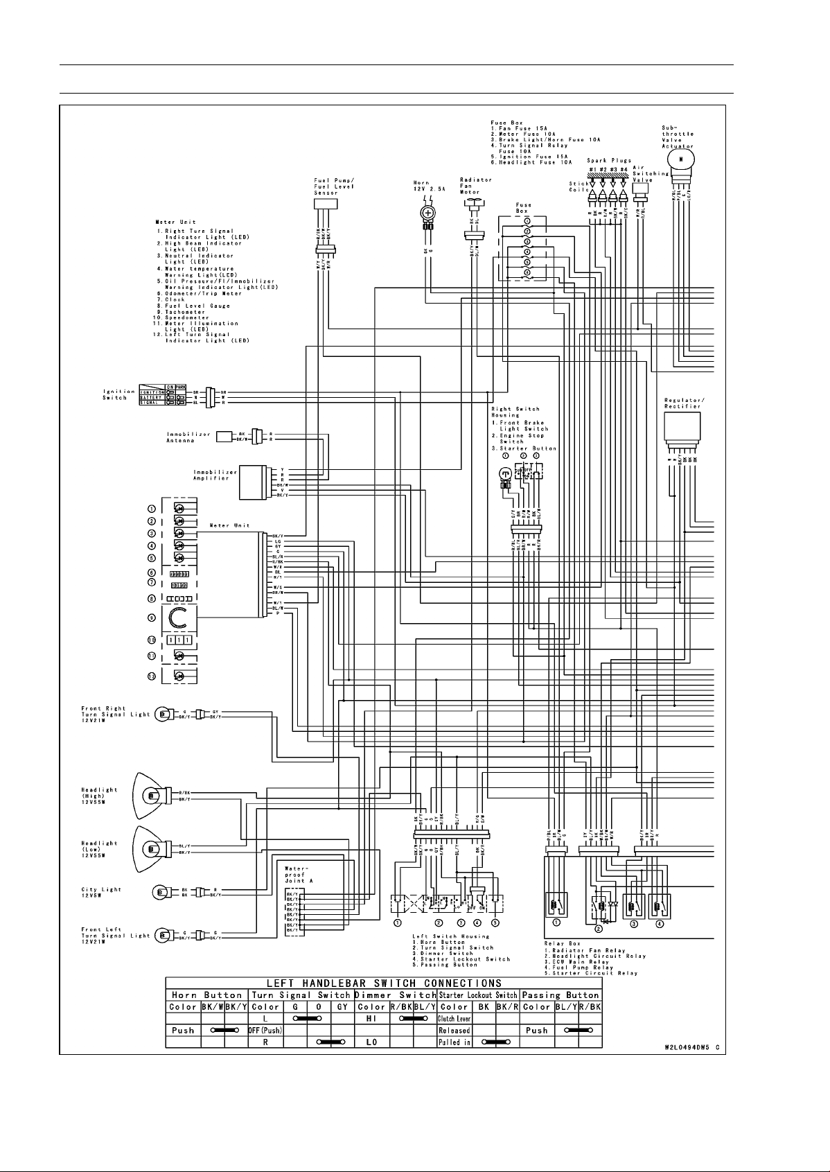
16-18 ELECTRICAL SYSTEM
Wiring Diagram (Other than US and CA Models)
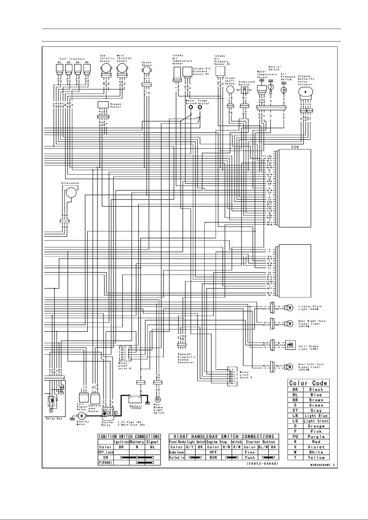
ELECTRICAL SYSTEM 16-19
Wiring Diagram (Other than US and CA Models)
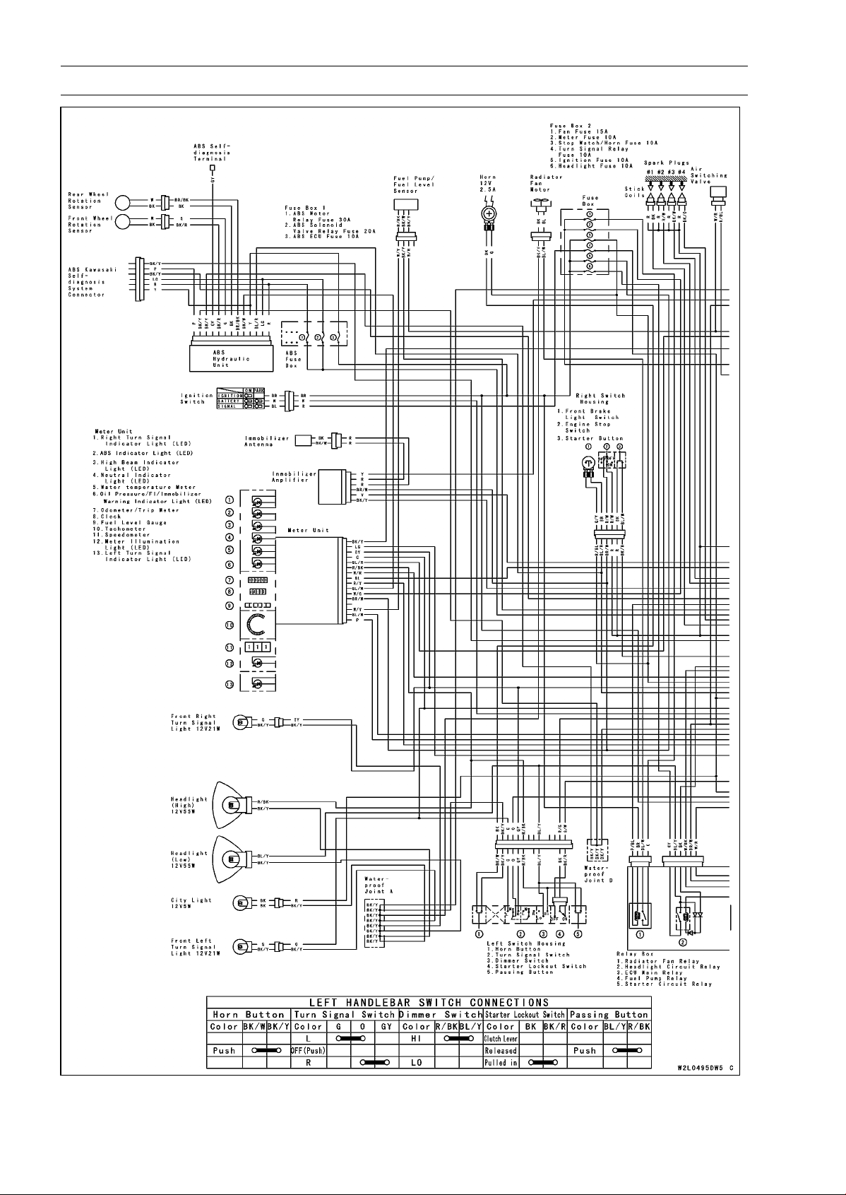
16-20 ELECTRICAL SYSTEM
Wiring Diagram (ABS Equipped Models)
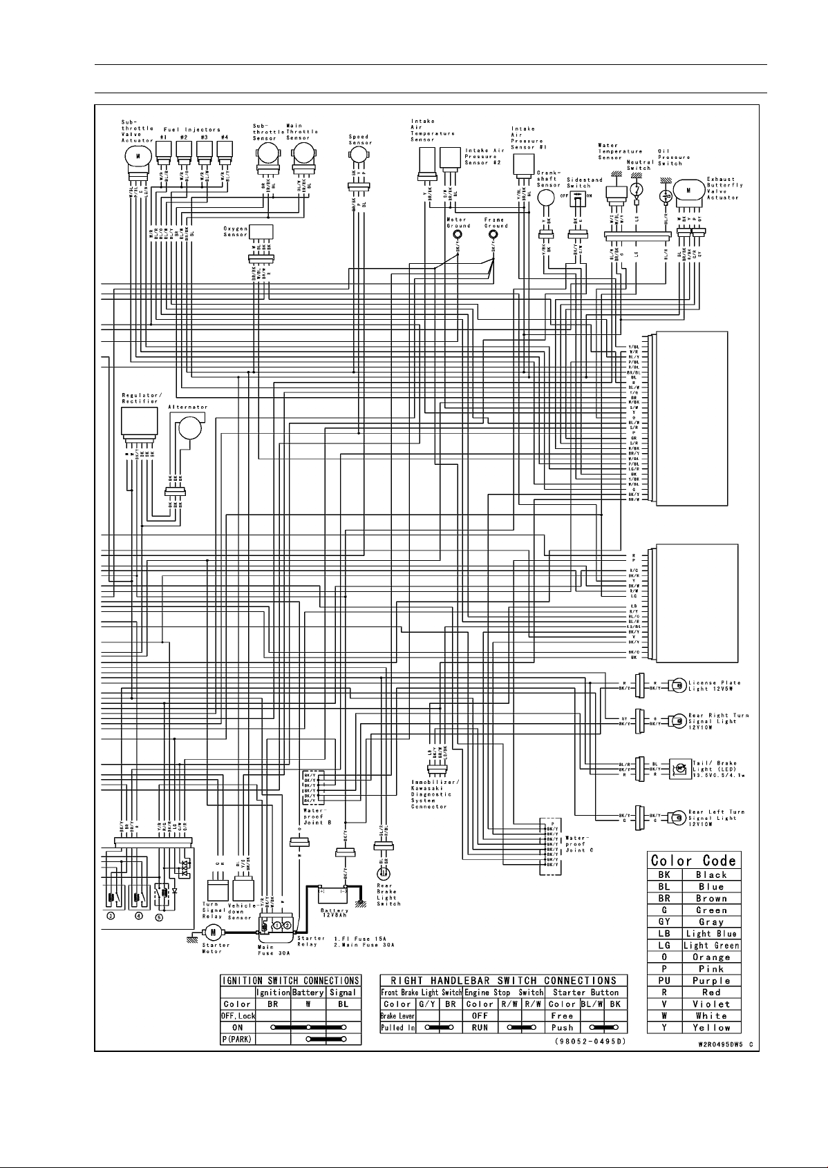
ELECTRICAL SYSTEM 16-21
Wiring Diagram (ABS Equipped Models)

16-22 ELECTRICAL SYSTEM
Precautions
There are a number of important precautions that are
musts when servicing electrical systems. Learn and ob-
serve all the rules below.
○
Do not reverse the battery cable connections. This will
burn out the diodes on the electrical parts.
○
Always check battery condition before condemning other
parts of an electrical system. A fully charged battery is a
must for conducting accurate electrical system tests.
○
The electrical parts should never be struck sharply, as
with a hammer, or allowed to fall on a hard surface. Such
a shock to the parts can damage them.
○
To prevent damage to electrical parts, do not disconnect
the battery cables or any other electrical connections
when the ignition switch is ON, or while the engine is
running.
○
Because of the large amount of current, never keep the
starter button pushed when the starter motor will not turn
over, or the current may burn out the starter motor wind-
ings.
○
Take care not to short the cables that are directly con-
nected to the battery positive (+) terminal to the chassis
ground.
○
Troubles may involve one or in some cases all items.
Never replace a defective part without determining what
CAUSED the failure. If the failure was caused by some
other item or items, they must be repaired or replaced, or
the new replacement will soon fail again.
○
Make sure all connectors in the circuit are clean and tight,
and examine wires for signs of burning, fraying, etc. Poor
wires and bad connections will affect electrical system op-
eration.
○
Measure coil and winding resistance when the part is cold
(at room temperature).
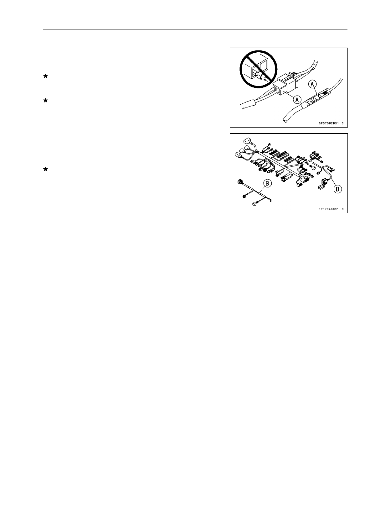
ELECTRICAL SYSTEM 16-23
Electrical Wiring
Wiring Inspection
•
Visually inspect the wiring for signs of burning, fraying,
etc.
If any wiring is poor, replace the damaged wiring.
•
Pull each connector [A] apart and inspect it for corrosion,
dirt, and damage.
If the connector is corroded or dirty, clean it carefully. If it
is damaged, replace it.
•
Check the wiring for continuity.
○
Use the wiring diagram to find the ends of the lead which
is suspected of being a problem.
○
Connect the hand tester between the ends of the leads.
Special Tool - Hand Tester: 57001-1394
○
Set the tester to the × 1 Ω range, and read the tester.
If the tester does not read 0 Ω, the lead is defective. Re-
place the lead or the wiring harness [B] if necessary.
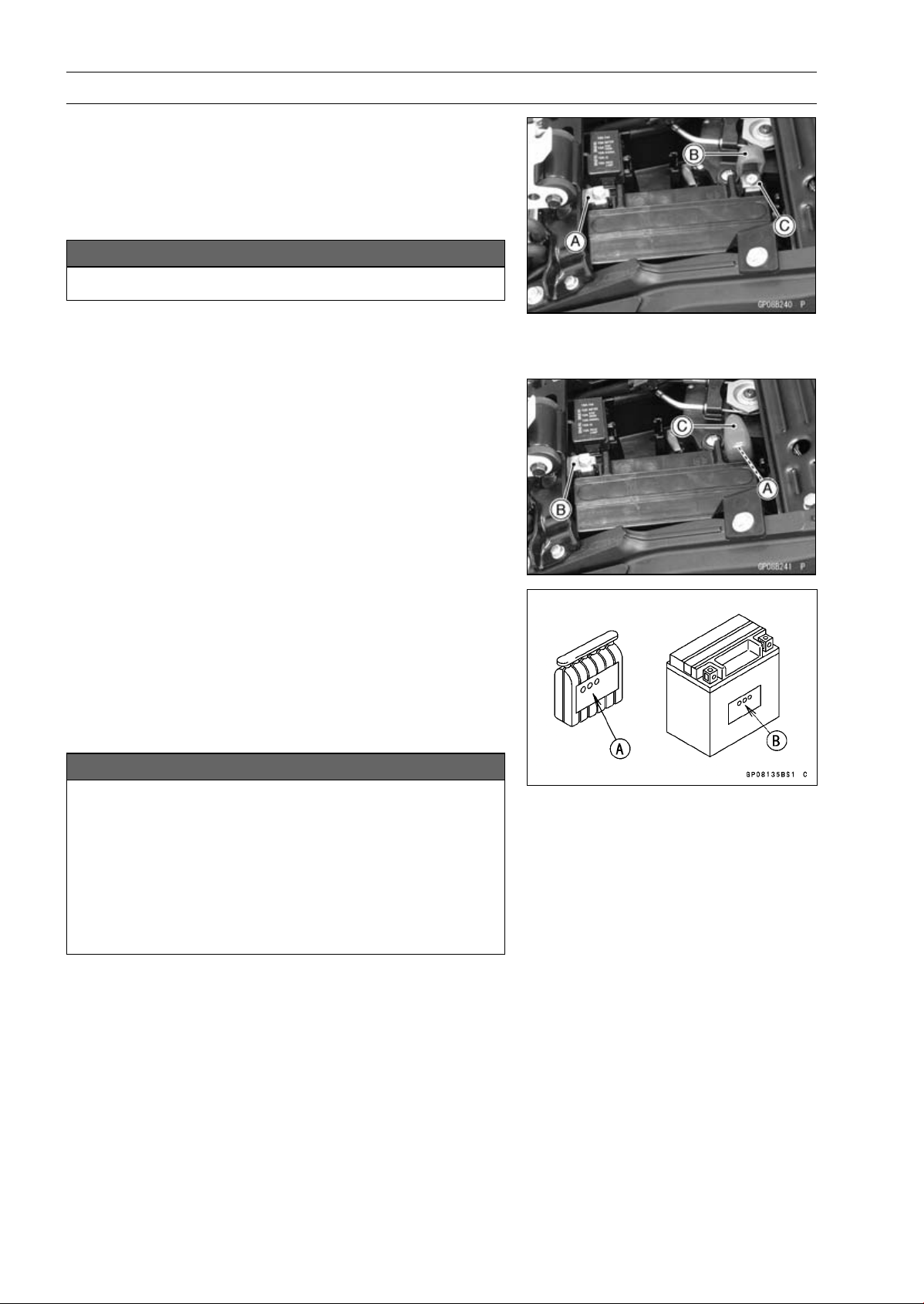
16-24 ELECTRICAL SYSTEM
Battery
Battery Removal
•
Turn off the ignition switch.
•
Remove:
Front Seat (see Front Seat Removal in the Frame chap-
ter)
•
Disconnect the negative (–) cable [A].
NOTICE
Be sure to disconnect the negative (–) cable first.
•
Slide out the positive (+) terminal cap [B] and disconnect
the positive (+) cable [C].
•
Remove the battery.
Battery Installation
•
Turn off the ignition switch.
•
Put the battery into the battery case.
•
Install the positive (+) cable [A] first.
•
Install the negative (–) cable [B].
•
Apply a light coat of grease on the terminals to prevent
corrosion.
•
Cover the Positive (+) terminal with the cap [C].
Battery Activation
Electrolyte Filling
•
Make sure that the model name [A] of the electrolyte con-
tainer matches the model name [B] of the battery. These
names must be the same.
Battery Model Name
ZR1000D/E: YTX9-BS
NOTICE
Each battery comes with its own specific elec-
trolyte container; using the wrong container may
overfill the battery with incorrect electrolyte, which
can shorten battery life and deteriorate battery per-
formance. Be sure to use the electrolyte container
with the same model name as the battery since the
electrolyte volume and specific gravity vary with
the battery type.
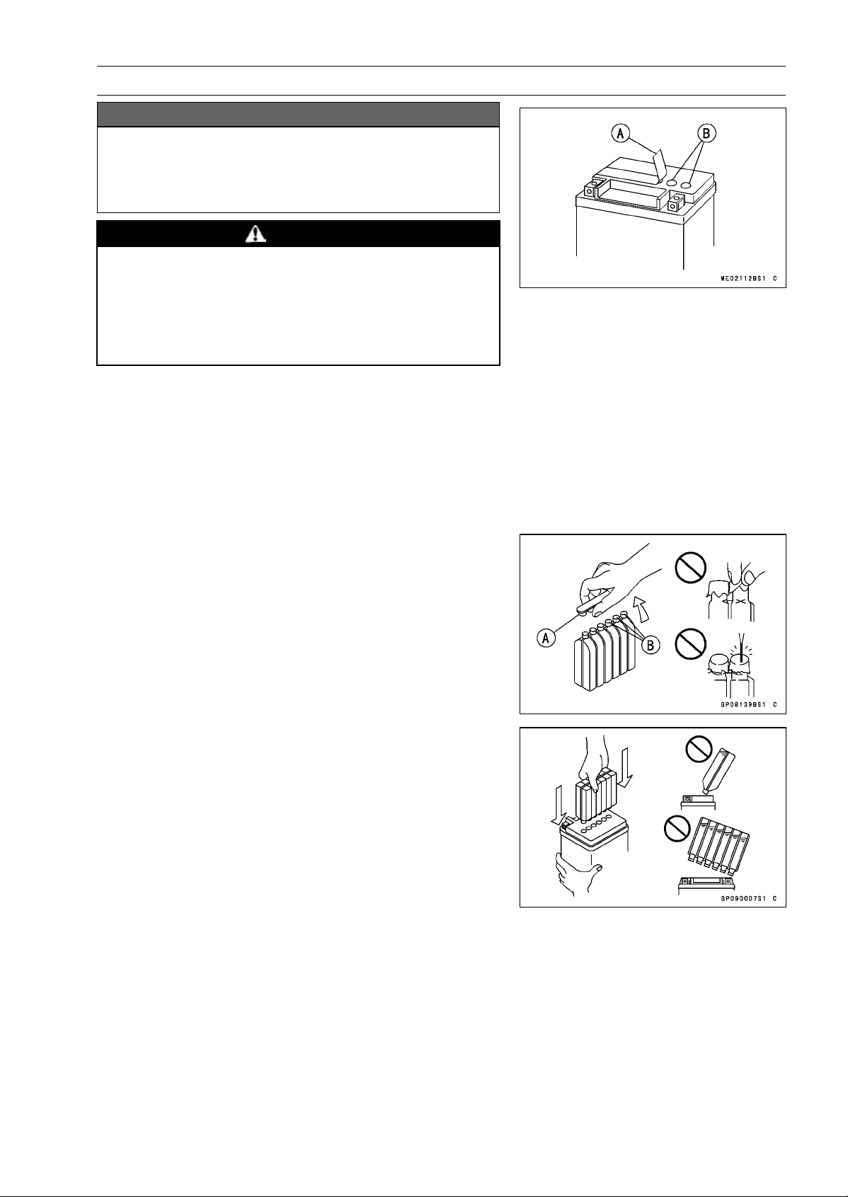
ELECTRICAL SYSTEM 16-25
Battery
NOTICE
Do not remove the aluminum sealing sheet [A] from
the filler ports [B] until just prior to use. Be sure to
use the dedicated electrolyte container for correct
electrolyte volume.
DANGER
Sulfuric acid in battery electrolyte can cause severe
burns. To prevent burns, wear protective clothing
and safety glasses when handling electrolyte. If
the electrolyte comes in contact with your skin or
eyes, wash the area with liberal amounts of water
and seek medical attention for more severe burns.
•
Place the battery on a level surface.
•
Check to see that the sealing sheet has no peeling, tears,
or holes in it.
•
Remove the sealing sheet.
NOTE
○
The battery is vacuum sealed. If the sealing sheet has
leaked air into the battery, it may require a longer initial
charge.
•
Remove the electrolyte container from the vinyl bag.
•
Detach the strip of caps [A] from the container and set
aside, these will be used later to seal the battery.
NOTE
○
Do not pierce or otherwise open the sealed cells [B] of
the electrolyte container. Do not attempt to separate
individual cells.
•
Place the electrolyte container upside down with the six
sealed cells into the filler ports of the battery. Hold the
container level, push down to break the seals of all six
cells. You will see air bubbles rising into each cell as the
ports fill.
NOTE
○
Do not tilt the electrolyte container.
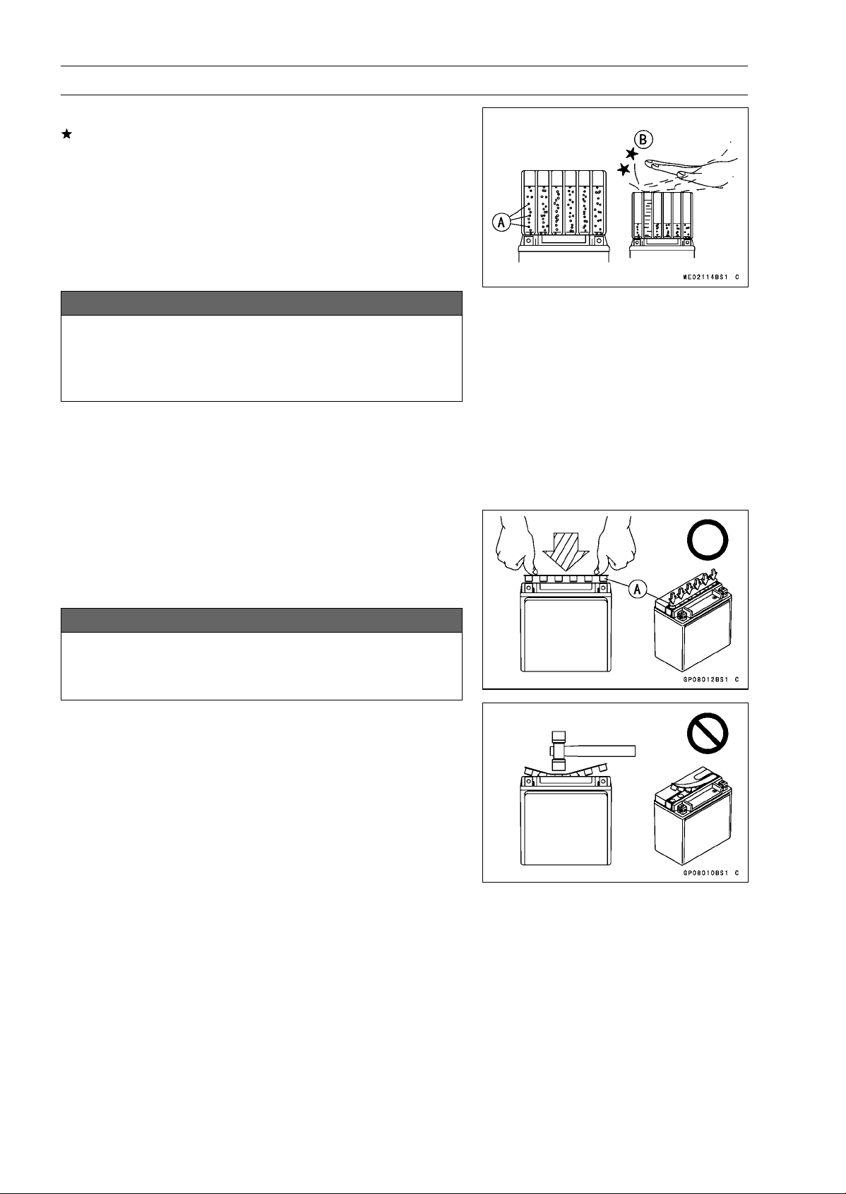
16-26 ELECTRICAL SYSTEM
Battery
•
Check the electrolyte flow.
If no air bubbles [A] are coming up from the filler ports, or
if the container cells have not emptied completely, tap the
container [B] a few times.
NOTE
○
Be careful not to have the battery fall down.
•
Keep the container in place. Don’t remove the container
from the battery, the battery requires all the electrolyte
from the container for proper operation.
NOTICE
Removal of the container before it is completely
empty can shorten the service life of the battery.
Do not remove the container until it is completely
empty.
•
After filling, let the battery sit for 20 ∼ 60 minutes with the
electrolyte container kept in place, which is required for
the electrolyte to fully permeate into the plates.
•
Make sure that the container cells have emptied com-
pletely, and remove the container from the battery.
•
Place the strip of caps [A] loosely over the filler ports,
press down firmly with both hands to seat the strip of caps
into the battery (don’t pound or hammer). When properly
installed, the strip of caps will be level with the top of the
battery.
NOTICE
Once the strip of caps is installed onto the battery,
never remove the caps, nor add water or electrolyte
to the battery.
NOTE
○
Charging the battery immediately after filling can
shorten service life.

ELECTRICAL SYSTEM 16-27
Battery
Initial Charge
•
Newly activated sealed batteries require an initial charge.
Standard Charge:
0.9 A × 5
∼ 10 hours
If using a recommended battery charger, follow the
charger’s instructions for newly activated sealed battery.
Kawasaki-recommended chargers:
Battery Mate 150-9
OptiMate PRO 4-S/PRO S/PRO2
Yuasa MB-2040/2060
Christie C10122S
If the above chargers are not available, use equivalent
one.
•
Let battery sit 30 minutes after initial charge, then check
voltage using a voltmeter. (Voltage immediately after
charging becomes temporarily high. For accurate mea-
suring, let the battery sit for given time.)
NOTE
○
Charging rates will vary depending on how long the
battery has been stored, temperature, and the type of
charger used. If voltage is not at least 12.8 V, repeat
charging cycle.
○
To ensure maximum battery life and customer satisfac-
tion, it is recommended the battery be load tested at
three times its amp-hour rating for 15 seconds.
Re-check voltage and if less than 12.8 V repeat the
charging cycle and load test. If still below 12.8 V the
battery is defective.
Precautions
1) No need of topping-up
No topping-up is necessary in this battery until it ends its life under normal use. F
orcibly prying
off the seal cap to add water is very dangerous. Never do that.
2) Refreshing charge.
If an engine will not start, a horn sounds weak, or lamps are dim, it indicates the battery has been
discharged. Give refresh charge for 5 to 10 hours with charge current shown in the specification
(see Refreshing Charge).
When a fast charge is inevitably required, do it following precisely the maximum charge current
and time conditions indicated on the battery.
NOTICE
This battery is designed to sustain no unusual deterioration if refresh-charged according
to the method specified above. H
owever, the battery’s performance may be reduced no-
ticeably if charged under conditions other than given above. Never remove the seal cap
during refresh charge.
If by chance an excessive amount of gas is generated due to overcharging, the relief valve
releases the gas to keep the battery normal.
3) When you do not use the motorcycle for months.
Give a refresh charge before you store the motorcycle and store it with the negative cable re-
moved. Give a refresh charge once a month during storage.
4) Battery life.
If the battery will not start the engine even after several refresh charges, the battery has ex-
ceeded its useful life. Replace it (Provided, however, the vehicle’s starting system has no prob-
lem).
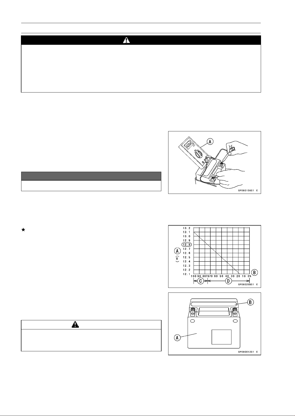
16-28 ELECTRICAL SYSTEM
Battery
DANGER
Batteries produce an explosive gas mixture of hydrogen and oxygen that can cause seri-
ous injury and burns if ignited. Keep the battery away from sparks and open flames during
charging. When using a battery charger, connect the battery to the charger before turning
on the charger. This procedure prevents sparks at the battery terminals which could ignite
any battery gases. The electrolyte contains sulfuric acid. Be careful not to have it touch
your skin or eyes. If touched, wash it off with liberal amount of water and seek medial at-
tention for more severe burns.
Interchange
A sealed battery can fully display its performance only when combined with a proper vehicle electric
system. Therefore, replace a sealed battery only on a motorcycle which was originally equipped with
a sealed battery.
Be careful, if a sealed battery is installed on a motorcycle which had an ordinary battery as original
equipment, the sealed battery’s life will be shortened.
Charging Condition Inspection
○
Battery charging condition can be checked by measuring
battery terminal voltage with a digital voltmeter [A].
•
Remove:
Seats (see Seats section in the Frame chapter)
•
Disconnect the battery terminals.
NOTICE
Be sure to disconnect the negative (–) cable first.
•
Measure the battery terminal voltage.
NOTE
○
Measure with a digital voltmeter which can be read one
decimal place voltage.
If the reading is 12.8 V or more, no refresh charge is re-
quired, however, if the read is below the specified, refresh
charge is required.
Battery Terminal Voltage
Standard: 12.8 V or more
Terminal Voltage (V) [A]
Battery Charge Rate (%) [B]
Good [C]
Refresh charge is required [D]
Refreshing Charge
•
Remove the battery [A] (see Battery Removal).
•
Do refresh charge by following method according to the
battery terminal voltage.
WARNING
This battery is sealed type. Never remove sealing
cap [B] even at charging. Never add water. Charge
with current and time as stated below.
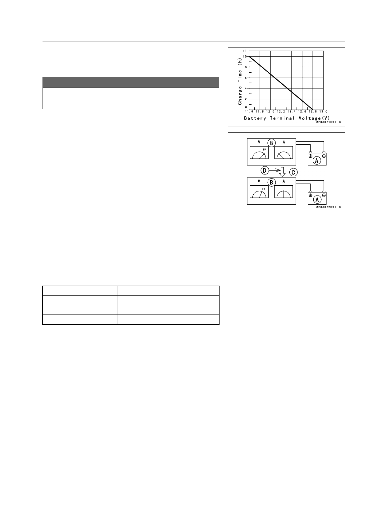
ELECTRICAL SYSTEM 16-29
Battery
Terminal Voltage: 11.5 ∼ less than 12.8 V
Standard Charge 0.9 A × 5
∼ 10 h (see following chart)
Quick Charge
4A×1h
NOTICE
If possible, do not quick charge. If quick charge is
done unavoidably, do standard charge later on.
Terminal Voltage: less than 11.5 V
Charging Method:
0.9A×20h
NOTE
○
Increase the charging voltage to a maximum voltage of
25 V if the battery will not accept current initially. Charge
for no more than 5 minutes at the increased voltage then
check if the battery is drawing current. If the battery
will accept current decrease the voltage and charge by
the standard charging method described on the battery
case. If the battery will not accept current after 5 min-
utes, replace the battery.
Battery [A]
Battery Charger [B]
Standard Value [C]
Current starts to flow [D]
•
Determine the battery condition after refresh charge.
○
Determine the condition of the battery left for 30 minutes
after completion of the charge by measuring the terminal
voltage according to the table below.
Criteria
Judgement
12.8 V or higher
Good
12.0 ∼ lower than 12.8 V
Charge insufficient → Recharge
lower than 12.0 V Unserviceable → Replace
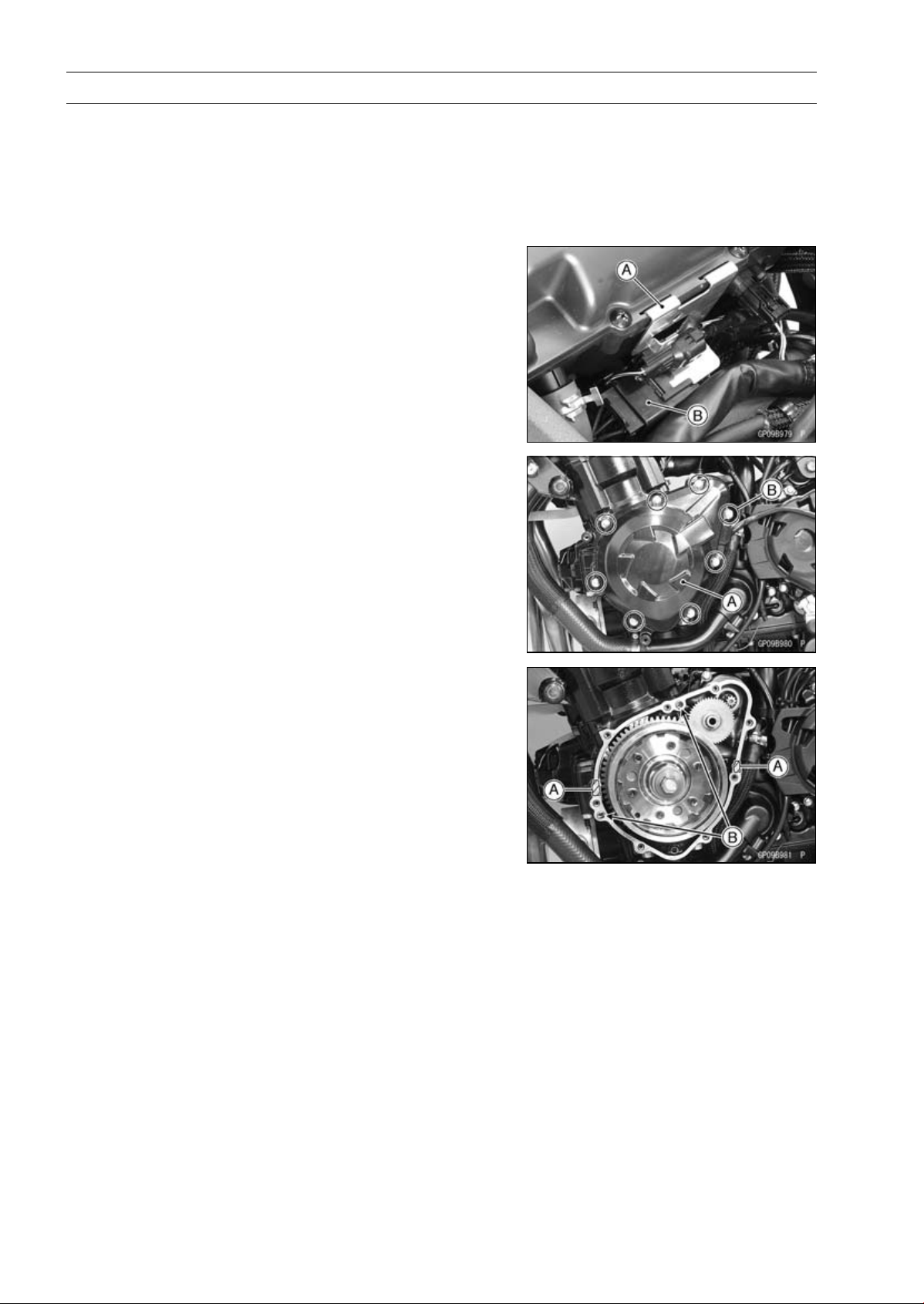
16-30 ELECTRICAL SYSTEM
Charging System
Alternator Cover Removal
•
Remove:
Left Lower Fairing (see Lower Fairing Removal in the
Frame chapter)
•
Support the fuel tank with a suitable bar (see Fuel Tank
Removal in the Fuel System (DFI) chapter).
•
Pull up the connector bracket [A].
•
Remove the alternator lead connector [B] from the
bracket.
•
Disconnect the alternator lead connector.
•
Place a suitable container under the alternator cover [A].
•
Remove:
Alternator Cover Bolts [B]
Alternator Cover
Alternator Cover Installation
•
Apply silicone sealant to the alternator lead grommet and
crankcase halves mating surface [A] on the front and rear
sides of the cover mount.
Sealant - Liquid Gasket, TB1211F: 92104-0004
•
Check that dowel pins [B] are in place on the crankcase.
•
Install a new gasket and the alternator cover.
•
Tighten:
Torque - Alternator Cover Bolts (Engine No.
∼
ZRT00DE013356): 9.8 N·m (1.0 kgf·m, 87
in·lb)
Alternator Cover Bolts: 12 N·m (1.2 kgf·m, 106
in·lb)
•
Run the alternator lead correctly (see Cable, Wire, and
Hose Routing section in the Appendix chapter).
•
Confirm that the drain hose and clamp are installed se-
curely and run the hose correctly (see Cable, Wire, and
Hose Routing section in the Appendix chapter).
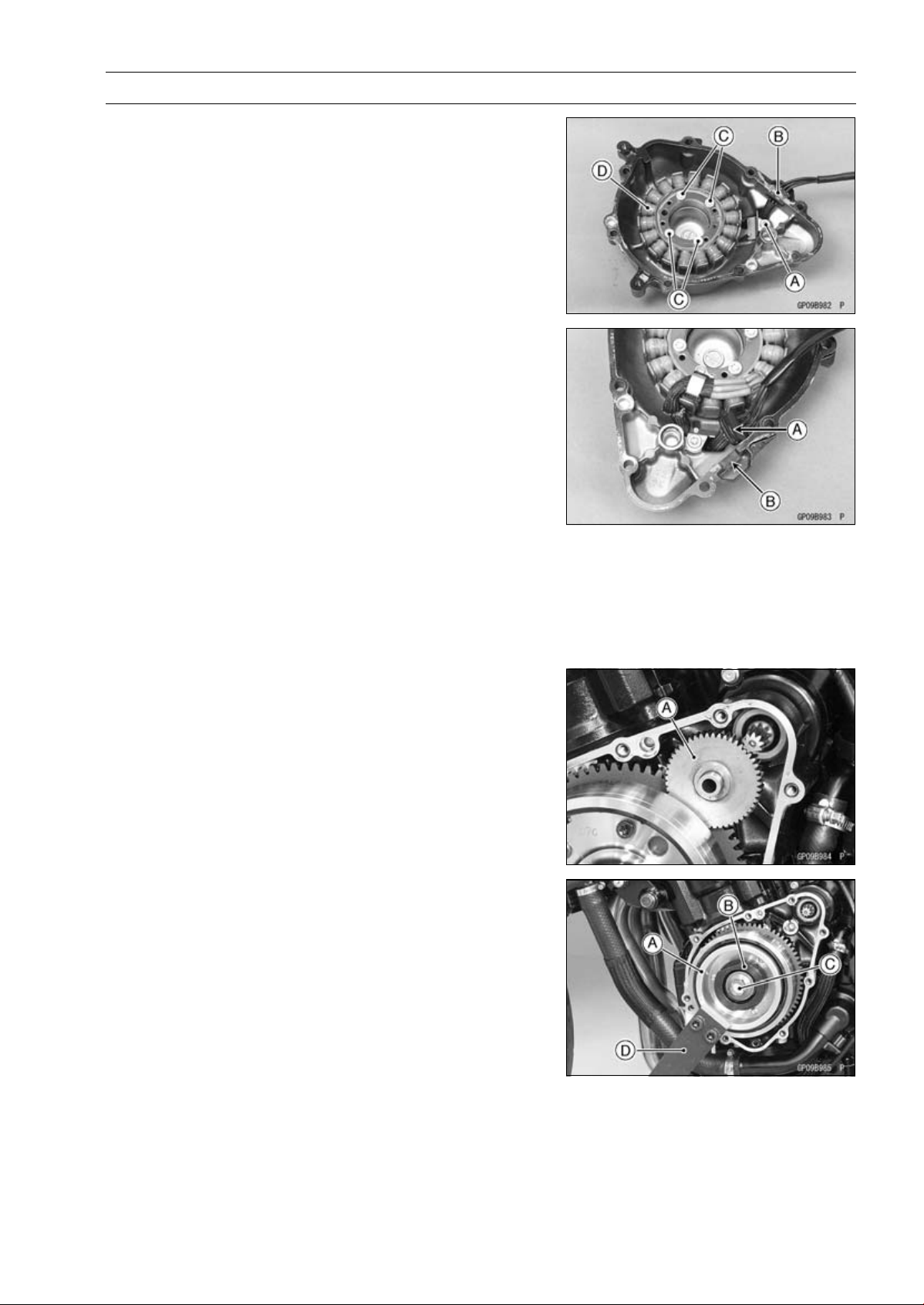
ELECTRICAL SYSTEM 16-31
Charging System
Stator Coil Removal
•
Remove:
Alternator Cover (see Alternator Cover Removal)
Holding Plate Bolt [A] and Plate
Alternator Lead Grommet [B]
Stator Coil Bolts [C]
•
Remove the stator coil [D] from the alternator cover.
Stator Coil Installation
•
Apply a non-permanent locking agent to the threads of
the stator coil bolts and tighten them.
Torque - Stator Coil Bolts: 12 N·m (1.2 kgf·m, 106 in·lb)
•
Secure the alternator lead with a holding plate.
•
Apply a non-permanent locking agent to the threads of
the plate bolt and tighten it.
Torque - Alternator Lead Holding Plate Bolt: 12 N·m (1.2
kgf·m, 106 in·lb)
•
Apply silicone sealant to the circumference of the alterna-
tor lead grommet [A], and fit the grommet into the notch
[B] of the cover securely.
Sealant - Liquid Gasket, TB1211F: 92104-0004
•
Install the alternator cover (see Alternator Cover Installa-
tion).
Alternator Rotor Removal
•
Remove:
Alternator Cover (see Alternator Cover Removal)
Starter Idle Gear [A]
•
Hold the alternator rotor steady with the rotor holder [A]
and stopper [B].
•
Remove the rotor bolt [C] and washer.
Special Tools - Grip [D]: 57001-1591
Stopper: 57001-1679
Rotor Holder: 57001-1690
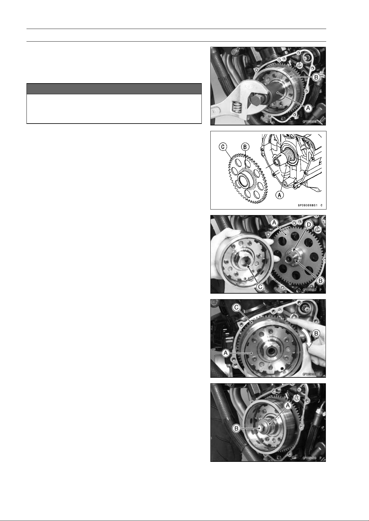
16-32 ELECTRICAL SYSTEM
Charging System
•
Using the flywheel puller [A], remove the alternator rotor
[B] from the crankshaft.
Special Tool - Flywheel Puller Assembly, M38 × 1.5/M35 ×
1.5: 57001-1615
NOTICE
Do not attempt to strike the alternator rotor itself.
Striking the rotor can cause the magnets to lose
their magnetism.
Alternator Rotor Installation
•
Apply a thin coat of molybdenum disulfide grease to the
crankshaft [A] and the outer surface [B] of the starter
clutch gear [C].
•
Install the starter clutch gear [A].
•
Using a cleaning fluid, clean off any oil or dirt on the fol-
lowing portions and dry them with a clean cloth.
Crankshaft Tapered Portion [B]
Alternator Rotor Tapered Portion [C]
•
Fit the woodruff key [D] securely in the slot in the crank-
shaft before installing the alternator rotor.
•
Install the alternator rotor [A] while turning [B] the starter
clutch gear [C] clockwise.
•
Using a cleaning fluid, clean off any oil or dirt on the
washer [A] and dry it with a clean cloth.
•
Install the washer.
NOTE
○
Confirm the alternator rotor fit or not to the crankshaft
before tightening it with specified torque.
•
Install the rotor bolt [B] and tighten it with 70 N·m (7.0
kgf·m, 52 ft·lb) of torque.
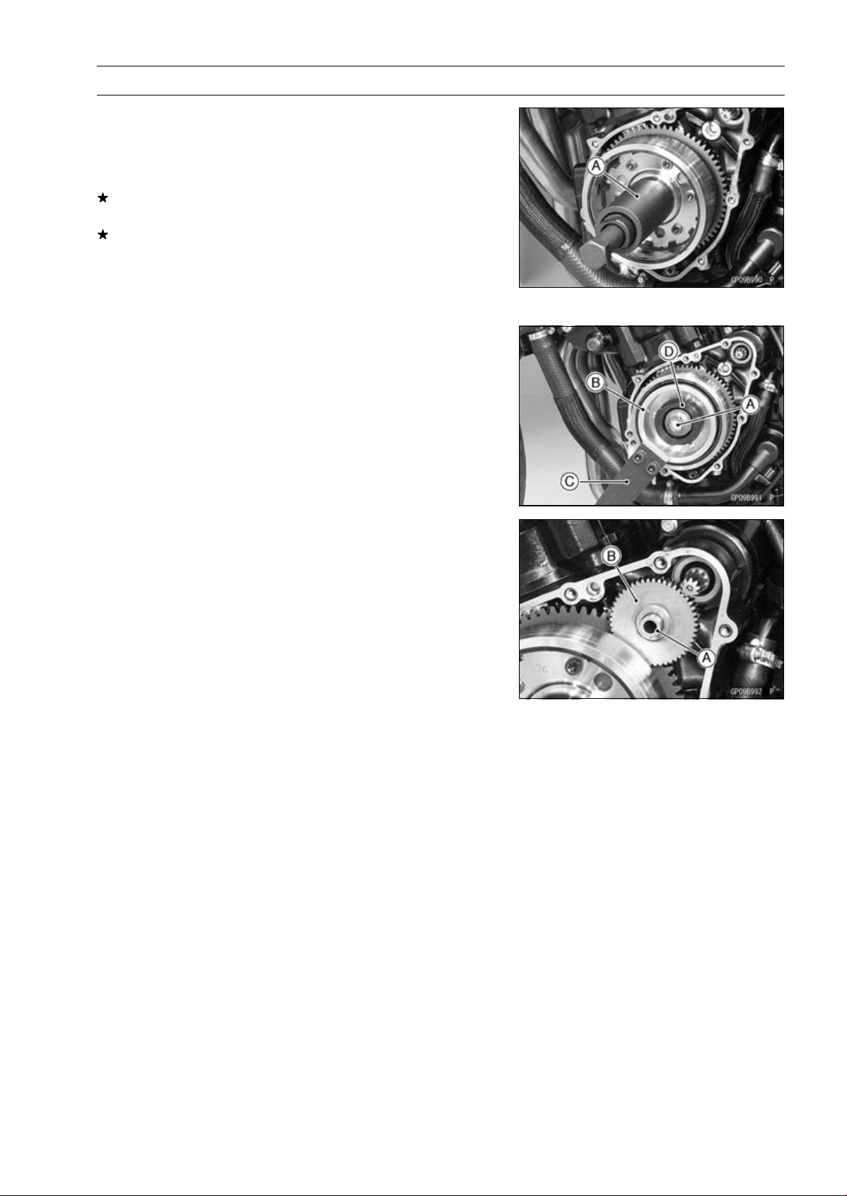
ELECTRICAL SYSTEM 16-33
Charging System
•
Remove the rotor bolt and washer.
•
Check the tightening torque with flywheel puller [A].
Special Tool - Flywheel Puller Assembly, M38 × 1.5/M35 ×
1.5: 57001-1615
If the rotor is not pulled out with 20 N·m (2.0 kgf·m, 15
ft·lb) of drawing torque, it is installed correctly.
If the rotor is pulled out with under 20 N·m (2.0 kgf·m, 15
ft·lb) of drawing torque, clean off any oil dirt or flaw of the
crankshaft and rotor tapered portion, and dry them with
a clean cloth. Then, confirm that it is not pulled out with
above torque.
•
Install the washer and rotor bolt.
•
Tighten the alternator rotor bolt [A] while holding the alter-
nator rotor steadily with the holder [B].
Special Tools - Grip [C]: 57001-1591
Rotor Holder: 57001-1690
Stopper [D]: 57001-1679
Torque - Alternator Rotor Bolt: 155 N·m (15.8 kgf·m, 114
ft·lb)
•
Apply a thin coat of molybdenum disulfide grease to the
shaft [A], and install it and starter idle gear [B].
•
Install the alternator cover (see Alternator Cover Installa-
tion).
Alternator Inspection
There are three types of alternator failures: short, open
(wire burned out), or loss in rotor magnetism. A short or
open in one of the coil wires will result in either a low output,
or no output at all. A loss in rotor magnetism, which may be
caused by dropping or hitting the alternator, by leaving it
near an electromagnetic field, or just by aging, will result in
low output.
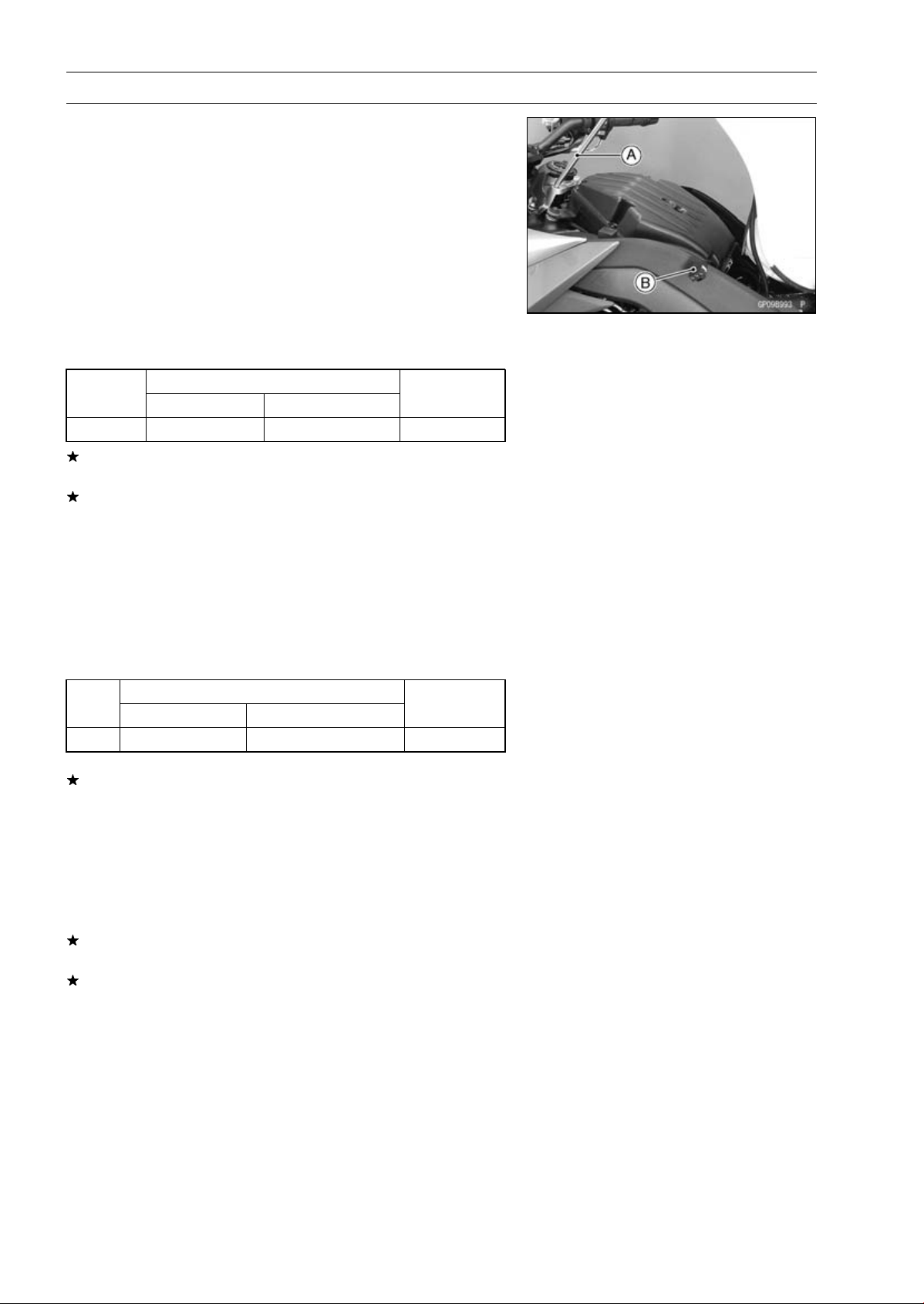
16-34 ELECTRICAL SYSTEM
Charging System
•
To check the alternator output voltage, do the following
procedures.
○
Turn off the ignition switch.
○
Support the fuel tank with a suitable bar [A] (see Fuel Tank
Removal in the Fuel System (DFI) chapter).
○
Disconnect the alternator lead connector [B] (see alterna-
tor Cover Removal).
○
Connect the hand tester as shown in the table 1.
○
Start the engine.
○
Run it at the rpm given in the table 1.
○
Note the voltage readings (total 3 measurements).
Table 1 Alternator Output Voltage
Connections
Test er
Range
Test er (+ ) to Te s t e r ( – ) to
Reading
at 4 000 rpm
250 V AC One Black lead
Another Black lead 43 V or more
If the output voltage shows the value in the table, the al-
ternator operates properly.
If the output voltage shows a much higher than the value
in the table, the regulator/rectifier is damaged. A much
lower reading than that given in the table indicates that
the alternator is defective.
•
Check the stator coil resistance as follows.
○
Stop the engine.
○
Connect the hand tester as shown in the table 2.
○
Note the readings (total 3 measurement).
Table 2 Stator Coil Resistance at 20°C (68°F)
Connections
Test er
Range
Test er ( + ) to Te s t e r (– ) t o
Reading
×1Ω One Black lead
Another Black lead
0.18 ∼ 0.28 Ω
If there is more resistance than shown in the table, or no
hand tester reading (infinity) for any two leads, the stator
has an open lead and must be replaced. Much less than
this resistance means the stator is shorted, and must be
replaced.
•
Using the highest resistance range of the hand tester,
measure the resistance between each of the black leads
and chassis ground.
Any hand tester reading less than infinity (∞) indicates a
short, necessitating stator replacement.
If the stator coils have normal resistance, but the voltage
check showed the alternator to be defective; then the rotor
magnets have probably weakened, and the rotor must be
replaced.
Special Tool - Hand Tester: 57001-1394
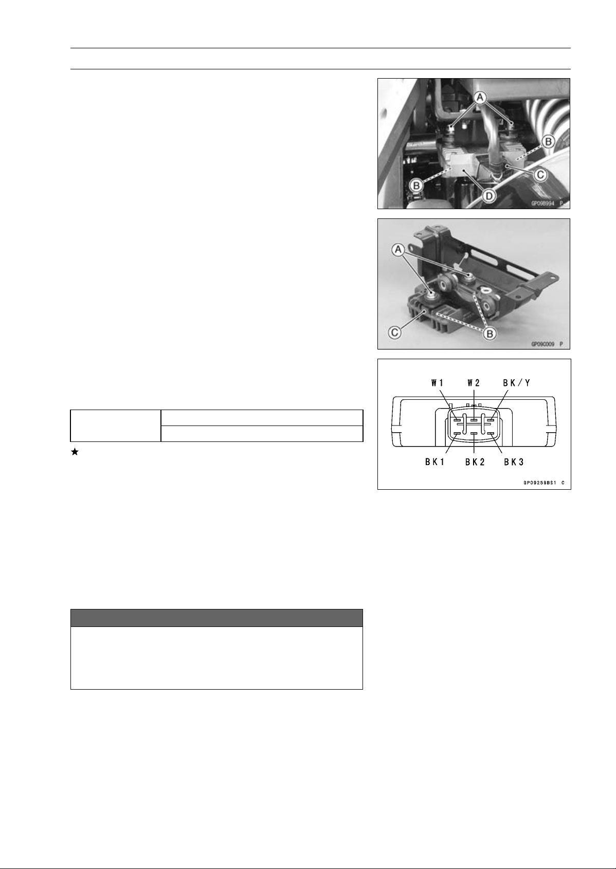
ELECTRICAL SYSTEM 16-35
Charging System
Regulator/Rectifier Inspection
ABS Non-equipment Models
•
Remove:
Bolts [A] and Nuts [B]
Connector [C] (Disconnect)
Regulator/Rectifier [D]
ABS Equipment Models
•
Remove:
ABS Hydraulic Unit (see ABS Hydraulic Unit Removal in
the Brakes chapter)
Bolts [A] and Nuts [B]
Regulator/Rectifier [C]
Rectifier Circuit Check
•
Check conductivity of the following pair of terminals.
Rectifier Circuit Inspection
W1-BK1, W1-BK2, W1-BK3
Tester connection
BK/Y-BK1, BK/Y-BK2, BK/Y-BK3
The resistance should be low in one direction and more
than ten times as much in the other direction. If any two
terminals are low or high in both directions, the rectifier is
defective and the regulator/rectifier must be replaced.
NOTE
○
The actual meter reading varies with the meter used
and the individual rectifier, but, generally speaking the
lower reading should be from zero to one half the scale.
Regulator Circuit Check
To test the regulator out of circuit, use three 12 V batteries
and a test light (12 V 3 ∼ 6 W bulb in a socket with leads).
NOTICE
The test light works as an indicator and also a cur-
rent limiter to protect the regulator/rectifier from ex-
cessive current. Do not use an ammeter instead of
a test light.
•
Check to be sure the rectifier circuit is normal before con-
tinuing.
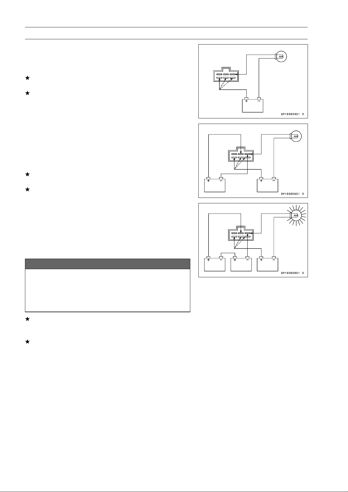
16-36 ELECTRICAL SYSTEM
Charging System
•
Do the 1st step regulator circuit test.
○
Connect the test light and the 12 V battery to the regula-
tor/rectifier as shown in the figure.
○
Check the BK1, BK2 and BK3 terminal respectively.
If the test light turns on, the regulator/rectifier is defective.
Replace it.
If the test light does not turn on, continue the test.
•
Do the 2nd step regulator circuit test.
○
Connect the test light and the 12 V battery in the same
manner as specified in the “Regulator Circuit Test-1st
Step”.
○
Apply 12 V to the W2 terminal.
○
Check the BK1, BK2 and BK3 terminal respectively.
If the test light turns on, the regulator/rectifier is defective.
Replace it.
If the test light does not turn on, continue the test.
•
Do the 3rd step regulator circuit test.
○
Connect the test light and the 12 V battery in the same
manner as specified in the “Regulator Circuit Test-1st
Step”.
○
Momentarily apply 24 V to the W2 terminal by adding a
12 V battery.
○
Check the BK1, BK2 and BK3 terminals respectively.
NOTICE
Do not apply more than 24 V. If more than 24 V is ap-
plied, the regulator/rectifier may be damaged. Do
not apply 24 V more than a few seconds. If 24 V
is applied for more than a few seconds, the regula-
tor/rectifier may be damaged.
If the test light did not light when the 24 V was applied
momentarily to the voltage monitoring terminal, the regu-
lator/rectifier is defective. Replace it.
If the regulator/rectifier passes all of the tests described,
it may still be defective. If the charging system still does
not work properly after checking all of the components
and the battery, test the regulator/rectifier by replacing it
with a known good unit.
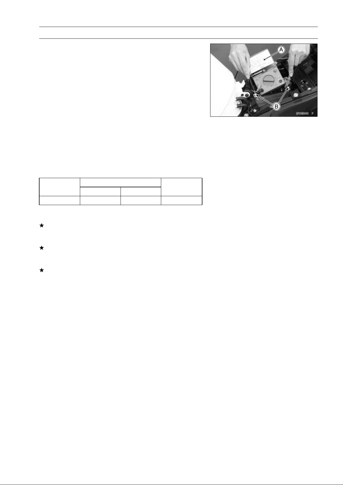
ELECTRICAL SYSTEM 16-37
Charging System
Charging Voltage Inspection
•
Check the battery condition (see Charging Condition In-
spection).
•
Warm up the engine to obtain actual alternator operating
conditions.
•
Check that the ignition switch is turned off, and connect
the hand tester [A] to the battery terminals [B].
Special Tool - Hand Tester: 57001-1394
•
Start the engine, and note the voltage readings at var-
ious engine speeds with the headlight turned on and
then turned off (To turn off the headlight, disconnect
the headlight connector on the headlight unit.). The
readings should show nearly battery voltage when the
engine speed is low, and, as the engine speed rises, the
readings should also rise. But they must be kept under
the specified voltage.
Charging Voltage
Connections
Tes ter Rang e
Test er (+ ) t o Te s t er ( –) t o
Reading
25 V DC Battery (+) Battery (–)
14.2 ∼ 15.2 V
•
Turn off the ignition switch to stop the engine, and discon-
nect the hand tester.
If the charging voltage is kept between the values given in
the table, the charging system is considered to be working
normally.
If the charging voltage is much higher than the values
specified in the table, the regulator/rectifier is defective
or the regulator/rectifier leads are loose or open.
If the charging voltage does not rise as the engine speed
increases, then the regulator/rectifier is defective or the
alternator output is insufficient for the loads. Check the
alternator and regulator/rectifier to determine which part
is defective.
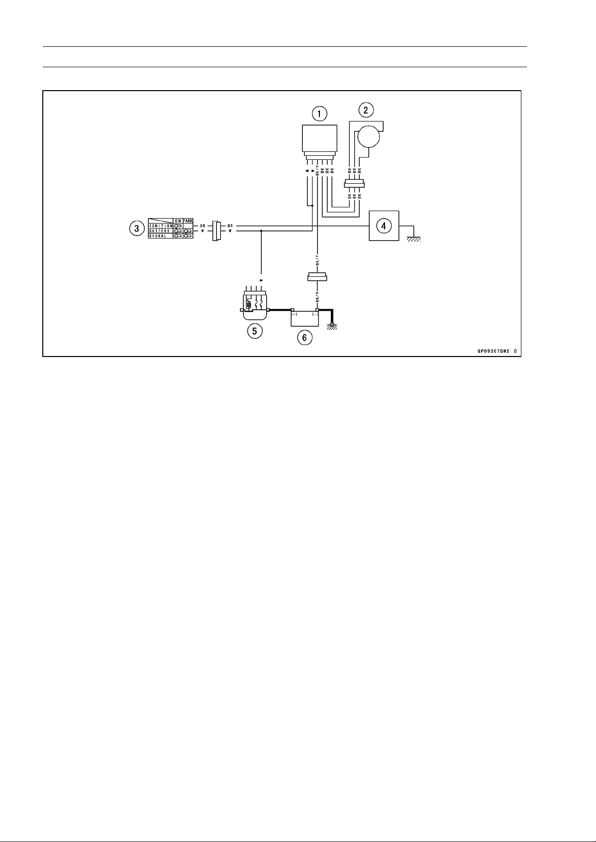
16-38 ELECTRICAL SYSTEM
Charging System
Charging System Circuit
1. Regulator/Rectifier
2. Alternator
3. Ignition Switch
4. Load
5. Main Fuse 30 A
6. Battery 12 V 8 Ah
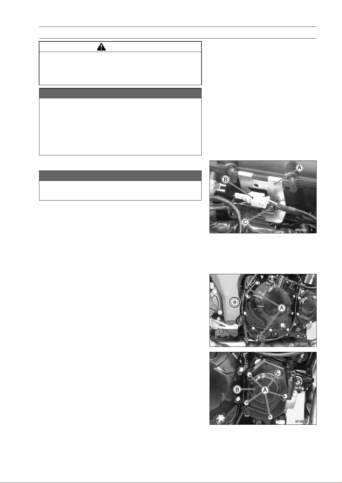
ELECTRICAL SYSTEM 16-39
Ignition System
WARNING
The ignition system produces extremely high volt-
age. Do not touch the spark plug, ignition coil or ig-
nition coil lead while the engine is running, or you
could receive a severe electrical shock.
NOTICE
Do not disconnect the battery cables or any other
electrical connections when the ignition switch is
ON, or while the engine is running. This is to pre-
vent ECU damage.
Do not install the battery backwards. The negative
side is grounded. This is to prevent damage to the
ECU.
Crankshaft Sensor Removal
NOTICE
Never drop the sensor, especially on a hard surface.
Such a shock to the sensor can damage it.
•
Remove the right lower fairing (see Lower Fairing Re-
moval in the Frame chapter).
•
Support the fuel tank with a suitable bar (see Fuel Tank
Removal in the Fuel System (DFI) chapter).
•
Pull up the connector bracket [A].
•
Remove the rear wheel rotation sensor connector [B]
(ABS equipped models) and crankshaft sensor lead
connector [C] from the bracket.
•
Disconnect the crankshaft sensor lead connector.
•
Clear the crankshaft sensor lead from the clamps [A].
•
Remove:
Crankshaft Sensor Cover Bolts [A]
Crankshaft Sensor Cover [B]
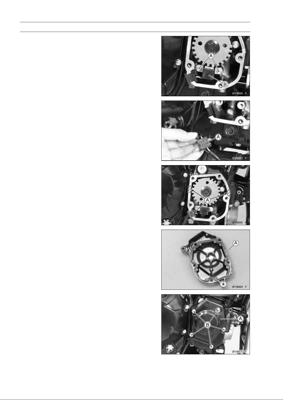
16-40 ELECTRICAL SYSTEM
Ignition System
•
Remove:
Crankshaft Sensor Bolts [A]
Crankshaft Sensor [B]
Crankshaft Sensor Installation
•
Route the crankshaft sensor lead correctly (see Cable,
Wire, and Hose Routing section in the Appendix chapter).
•
Tighten:
Torque - Crankshaft Sensor Bolts: 5.9 N·m (0.60 kgf·m, 52
in·lb)
•
Apply silicone sealant [A] to the crankshaft sensor lead
grommet and crankcase halves mating surface on the
front and rear sides of the crankshaft sensor cover mount.
Sealant - Liquid Gasket, TB1211F: 92104-0004
•
Replace the O-ring [A] in the crankshaft sensor cover with
a new one.
•
Install:
Crankshaft Sensor Cover [A]
•
Tighten the crankshaft sensor cover bolts [B].
Torque - Crankshaft Sensor Cover Bolts (Engine No.
∼
ZRT00DE013356): 9.8 N·m (1.0 kgf·m, 87 in·lb)
Crankshaft Sensor Cover Bolts: 12 N·m (1.2
kgf·m, 106 in·lb)
•
Run the crankshaft sensor lead correctly (see Cable,
Wire, and Hose Routing section in the Appendix chapter).
•
Confirm that the drain hose and clamp are installed se-
curely and run the hose correctly (see Cable, Wire, and
Hose Routing section in the Appendix chapter).
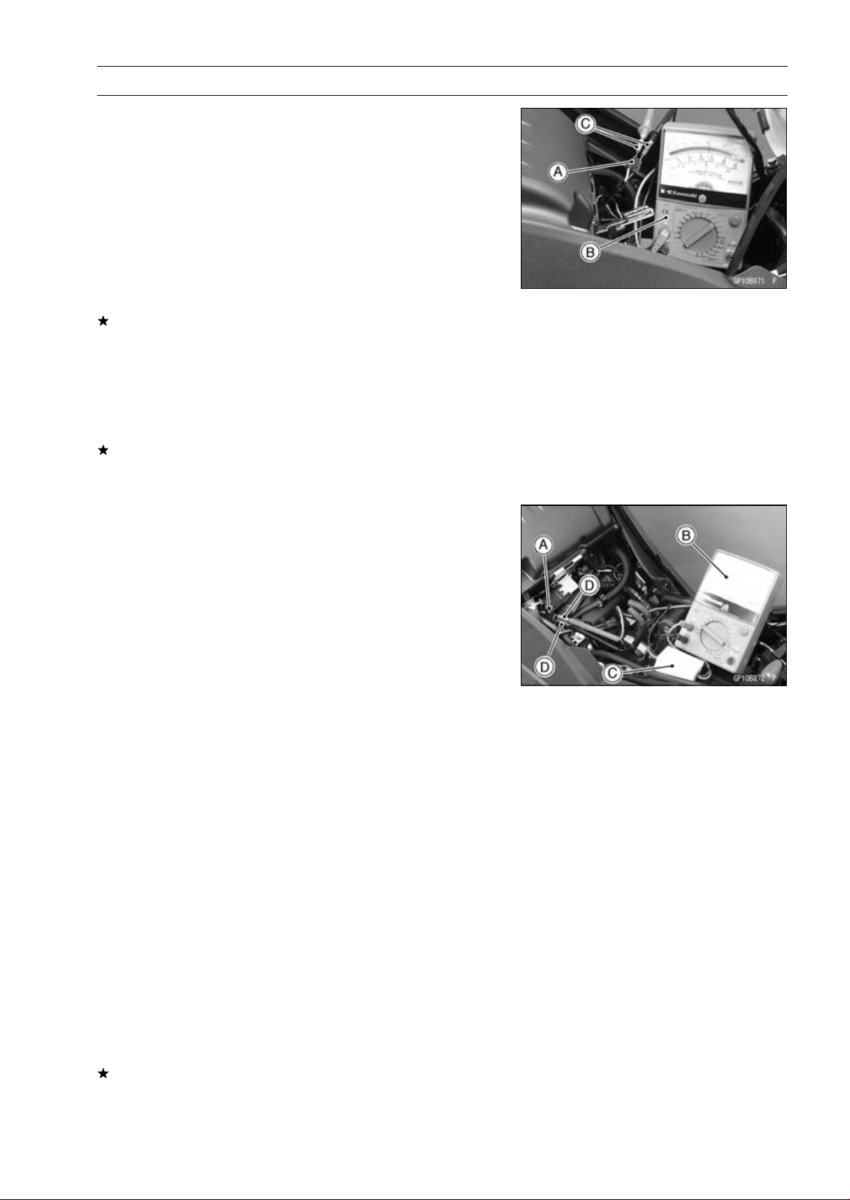
ELECTRICAL SYSTEM 16-41
Ignition System
Crankshaft Sensor Inspection
•
Remove:
Crankshaft Sensor Lead Connector [A] (see Crankshaft
Sensor Removal)
•
Set the hand tester [B] to the × 100 Ω range and connect
(+) lead to the yellow lead and (–) lead to the black lead
in the connector.
Special Tools - Hand Tester: 57001-1394
Needle Adapter Set [C]: 57001-1457
Crankshaft Sensor Resistance: 376
∼ 564
If there is more resistance than the specified value, the
coil has an open lead and must be replaced. Much less
than this resistance means the coil is shorted, and must
be replaced.
•
Using the highest resistance range of the tester, measure
the resistance between the crankshaft sensor leads and
chassis ground.
Any tester reading less than infinity (∞) indicates a short,
necessitating replacement of the crankshaft sensor as-
sembly.
Crankshaft Sensor Peak Voltage Inspection
NOTE
○
Be sure the battery is fully charged.
•
Remo
ve:
Fuel Tank (see Fuel Tank Removal in the Fuel System
(DFI) chapter)
Cr
ankshaft Sensor Lead Connector [A] (see Crankshaft
Sensor Removal)
•
Set the hand tester [B] to the DC 10 V range.
•
Connect the peak v
oltage adapter [C] to the hand tester
and crankshaft sensor leads in the connector.
Special Tools - Hand Tester: 57001-1394
Peak Voltage Adapter: 57001-1415
Type: KEK-54-9-B
Needle Adapter Set [D]: 57001-1457
Connections:
Crankshaft
Sensor Lead
Peak Voltage
Adapter
Hand Tester
Yellow
Red
(+)
Black
Black
(–)
•
Turn the ignition switch and engine stop switch ON.
•
Pushing the starter button, turn the engine 4 ∼ 5sec-
onds with the transmission gear in neutral to measure the
crankshaft sensor peak voltage.
•
Repeat the measurement 5 or more times.
Crankshaft Sensor Peak Voltage
Standard:
2.0 V or more
If the tester reading is not specified one, inspect the crank-
shaft sensor (see Crankshaft Sensor Inspection).
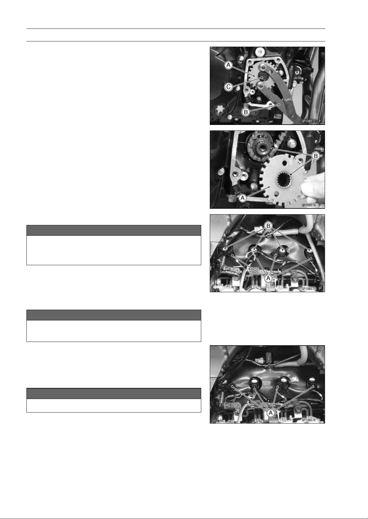
16-42 ELECTRICAL SYSTEM
Ignition System
Timing Rotor Removal
•
Remove the crankshaft sensor (see Crankshaft Sensor
Removal).
•
Remove the timing rotor [A].
○
Holding the timing rotor with the flywheel & pulley holder
[B] and remove the rotor bolt [C].
Special Tool - Flywheel & Pulley Holder: 57001-1605
Timing Rotor Installation
•
Install the timing rotor [A] with the their theeth [B] aligned.
•
Tighten:
Torque - Timing Rotor Bolt: 39 N·m (4.0 kgf·m, 29 ft·lb)
Special Tool - Flywheel & Pulley Holder: 57001-1605
Stick Coil Removal
NOTICE
Never drop the stick coils, especially on a hard sur-
face.
Such a shock to the stick coils can damage it.
•
Remove:
Air Cleaner Housing (see Air Cleaner Housing Removal
in the Fuel System (DFI) chapter)
•
Disconnect the stick coil connectors [A].
•
Pull the stick coils [B].
NOTICE
Do not pry the connector part of the coil while re-
moving the coil.
Stick Coil Installation
•
Insert the coil as shown being careful of the coil heads [A]
direction.
•
Be sure the stick coils are installed by pulling up it lightly.
•
Connect the connectors.
NOTICE
Do not tap the coil head while installing the coil.
•
Run the hoses and harness correctly (see Cable, Wire,
and Hose Routing section in the Appendix chapter).
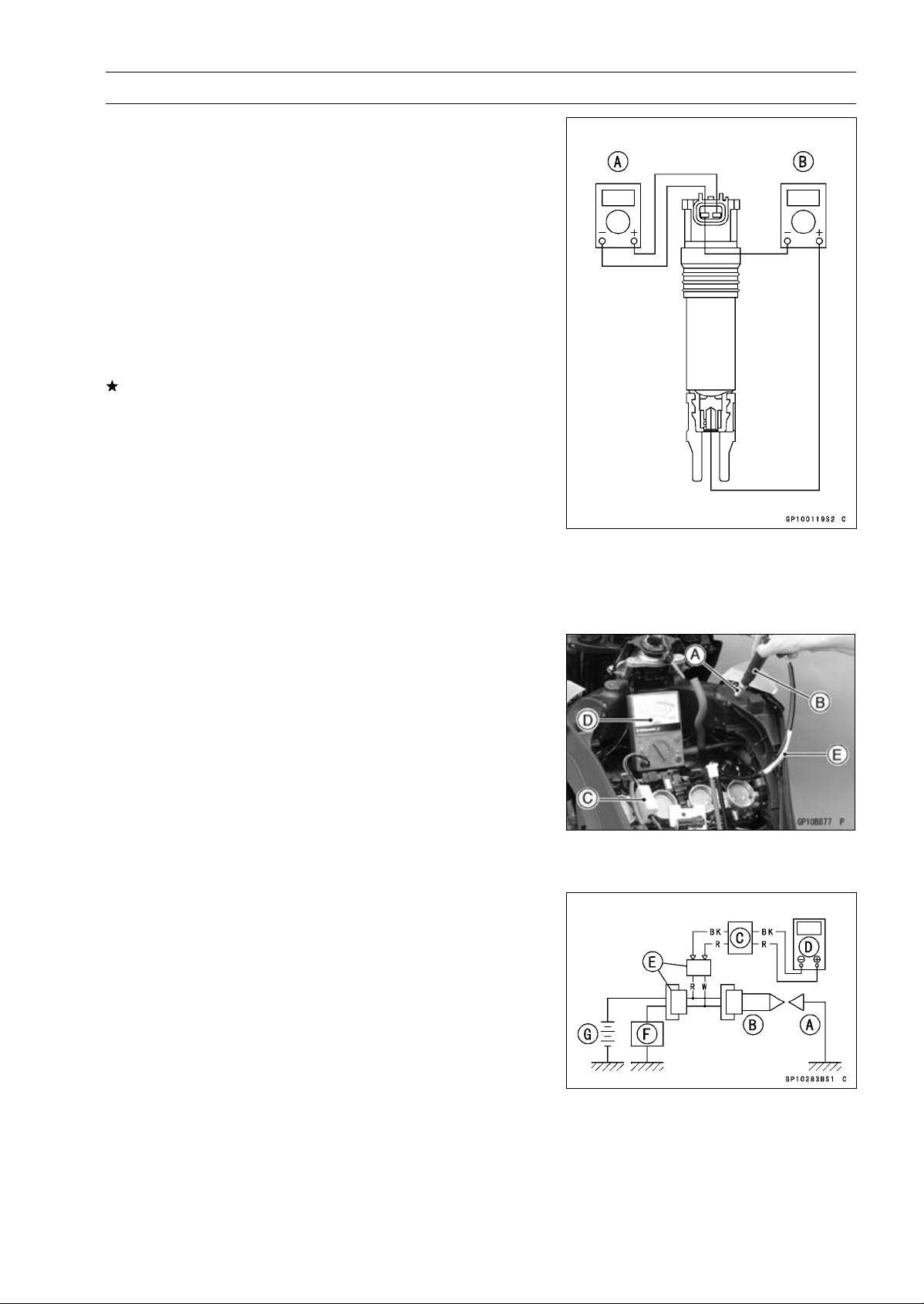
ELECTRICAL SYSTEM 16-43
Ignition System
Stick Coil Inspection
•
Remove the stick coils (see Stick Coil Removal).
•
Measure the primary winding resistance [A] as follows.
○
Connect the hand tester between the coil terminals.
○
Set the tester to the × 1 Ω range, and read the tester.
•
Measure the secondary winding resistance [B] as follows.
○
Connect the tester between the plug terminal and (–) coil
terminal.
○
Set the tester to the × 1 kΩ range and read the tester.
Stick Coil Winding Resistance
Primary Windings:
1.1
∼ 1.5
Secondary Windings: 10.8
∼ 16.2 k
If the tester does not read as specified, replace the coil.
Stick Coil Primary Peak Voltage Inspection
NOTE
○
Be sure the battery is fully charged.
•
Remove the stick coils (see Stick Coil Removal), but do
not remove the spark plugs.
•
Measure the primary peak voltage as follows.
○
Install the new spark plug [A] into each stick coil [B], and
ground them onto the engine.
○
Connect the peak voltage adapter [C] into the hand tester
[D] which is set to the DC 250 V range.
○
Connect the adapter to the lead wire-peak voltage
adapter [E] which is connected between the stick coil
connector and stick coil.
ECU [F]
Battery [G]
Special Tools - Hand Tester: 57001-1394
Peak Voltage Adapter: 57001-1415
Type: KEK-54-9-B
Lead Wire-Peak Voltage Adapter: 57001
-1449
Primary Lead Connection
Adapter (R, +) to lead wire-peak voltage adapter (W)
Adapter (BK, –) to lead wire-peak voltage adapter (R)
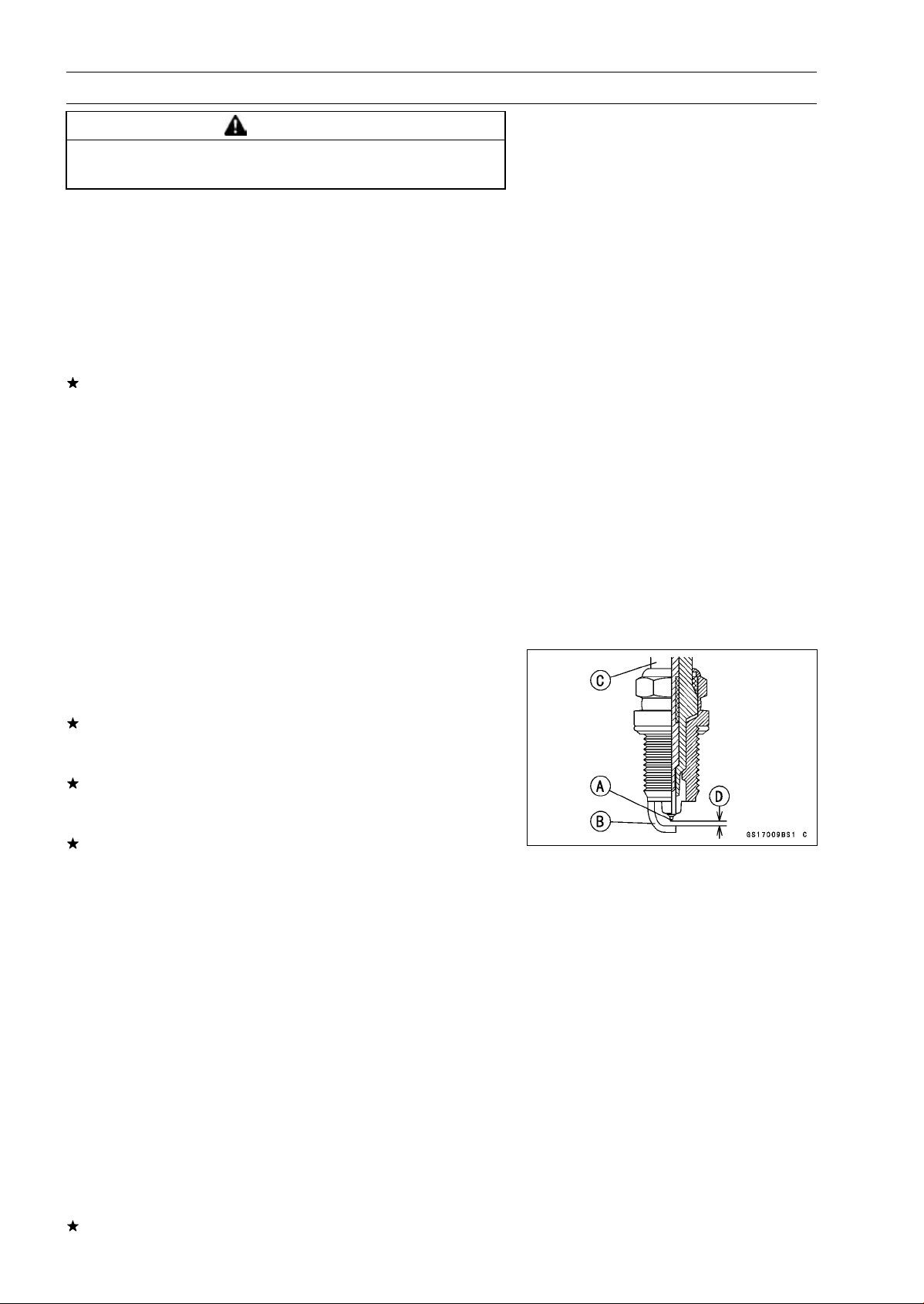
16-44 ELECTRICAL SYSTEM
Ignition System
WARNING
To avoid extremely high voltage shocks, do not
touch the spark plugs or tester connections.
•
Turn the ignition switch and the engine stop switch ON.
•
Pushing the starter button, turn the engine 4 ∼ 5 seconds
with the transmission in neutral to measure the primary
peak voltage.
•
Repeat the measurements 5 times for one stick coil.
Stick Coil Primary Peak Voltage
Standard:
100 V or more
•
Repeat the test for the other stick coil.
If the reading is less than the specified value, check the
following.
Stick Coils (see Stick Coil Inspection)
Crankshaft Sensor (see Crankshaft Sensor Inspection)
ECU (see ECU Power Supply Inspection in the Fuel Sys-
tem (DFI) chapter)
Spark Plug Removal
•
Refer to the Spark Plug Replacement in the Periodic
Maintenance chapter.
Spark Plug Installation
•
Refer to the Spark Plug Replacement in the Periodic
Maintenance chapter.
Spark Plug Condition Inspection
•
Remove the spark plugs (see Spark Plug Replacement).
•
Visually inspect the spark plugs.
If the spark plug center electrode [A] and/or side elec-
trode [B] are corroded or damaged, or if the insulator [C]
is cracked, replace the plug.
If the spark plug is dirtied or the carbon is accumulated,
replace the spark plug.
•
Measure the gap [D] with a wire-type thickness gauge.
If the gap is incorrect, replace the spark plug.
Spark Plug Gap: 0.8
∼ 0.9 mm (0.031 ∼ 0.035 in.)
•
Use the standard spark plug or its equivalent.
Spark Plug: NGK CR9EIA-9
Interlock Operation Inspection
•
Raise the rear wheel off the ground with stand.
•
Turn the engine stop switch ON (run position).
1st Check
•
Start the engine to the following conditions.
Condition:
Transmission Gear 1st Position
Clutch Lever Release
Sidestand Down or Up
○
Turn the ignition switch ON and push the starter button.
○
Then the starter motor should not turn when the starter
system circuit is normality.
If the engine is start, inspect the starter lockout switch,
sidestand switch, neutral switch and relay box.
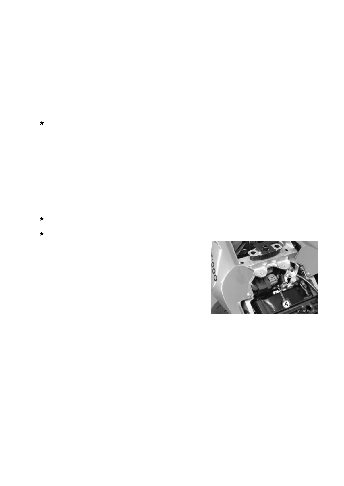
ELECTRICAL SYSTEM 16-45
Ignition System
2nd Check
•
Start the engine to the following conditions.
Condition:
Transmission Gear 1st Position
Clutch Lever Pulled in
Sidestand Up
○
Turn the ignition switch ON and push the starter button.
○
Then the starter motor should turn when the starter sys-
tem circuit is normality.
If the starter motor is not turn, inspect the starter lockout
switch, sidestand switch, relay box, and starter relay.
3rd Check
•
Inspect the engine for its secure stop after the following
operations are completed.
•
Run the engine to the following conditions.
Condition:
Transmission Gear 1st Position
Clutch Lever Pulled in
Sidestand Up
•
Set the sidestand on the ground, then the engine will stop.
If the engine does not stop, inspect the neutral switch,
sidestand switch and relay box.
If their parts are normality, replace the ECU.
IC Igniter Inspection
○
The IC igniter is built in the ECU [A].
•
Refer to the following items.
Interlock Operation Inspection (see Interlock Operation
Inspection)
Ignition System Troubleshooting (see Ignition System
section)
ECU Power Supply Inspection (see ECU Power Supply
Inspection in the Fuel System (DFI) chapter)
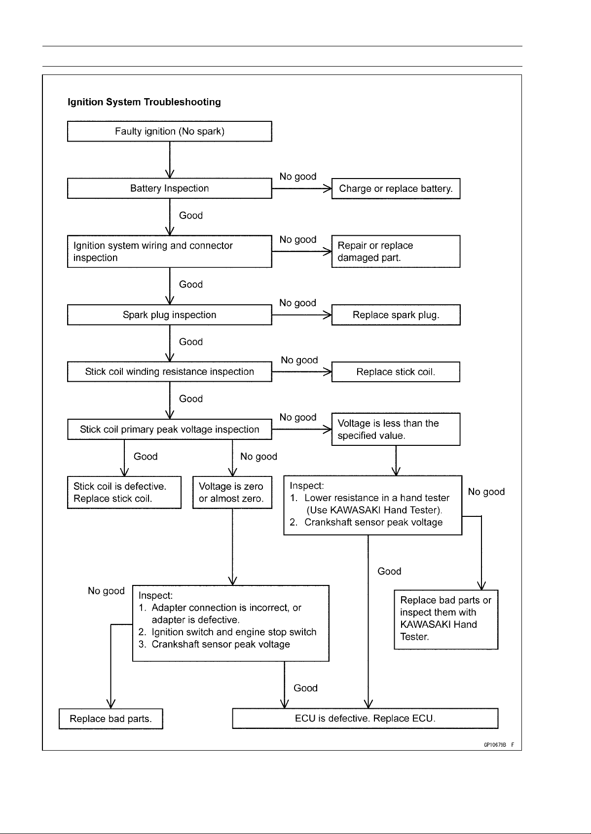
16-46 ELECTRICAL SYSTEM
Ignition System
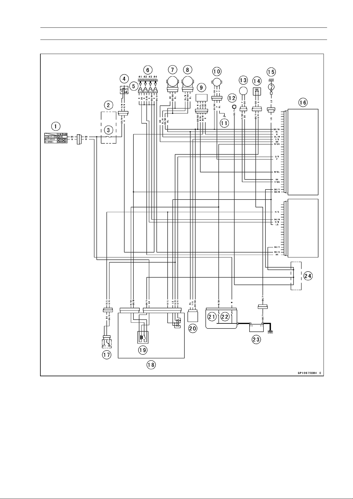
ELECTRICAL SYSTEM 16-47
Ignition System
Ignition System Circuit
1. Ignition Switch
2. Fuse Box
3. Ignition Fuse 15 A
4. Engine Stop Switch
5. Stick Coils
6. Spark Plugs
7. Subthrottle Sensor
8. Main Throttle Sensor
9. Oxygen Sensor (Equipped Models)
10. Speed Sensor
11. to Meter Unit
12. Meter Ground
13. Crankshaft Sensor
14. Sidestand Switch
15. Neutral Switch
16. ECU
17. Starter Lockout Switch
18. Relay Box
19. ECU Main Relay
20. Vehicle-down Sensor
21. FI Fuse 15 A
22. Main Fuse 30 A
23. Battery 12 V 8 Ah
24. Water-proof Joint C
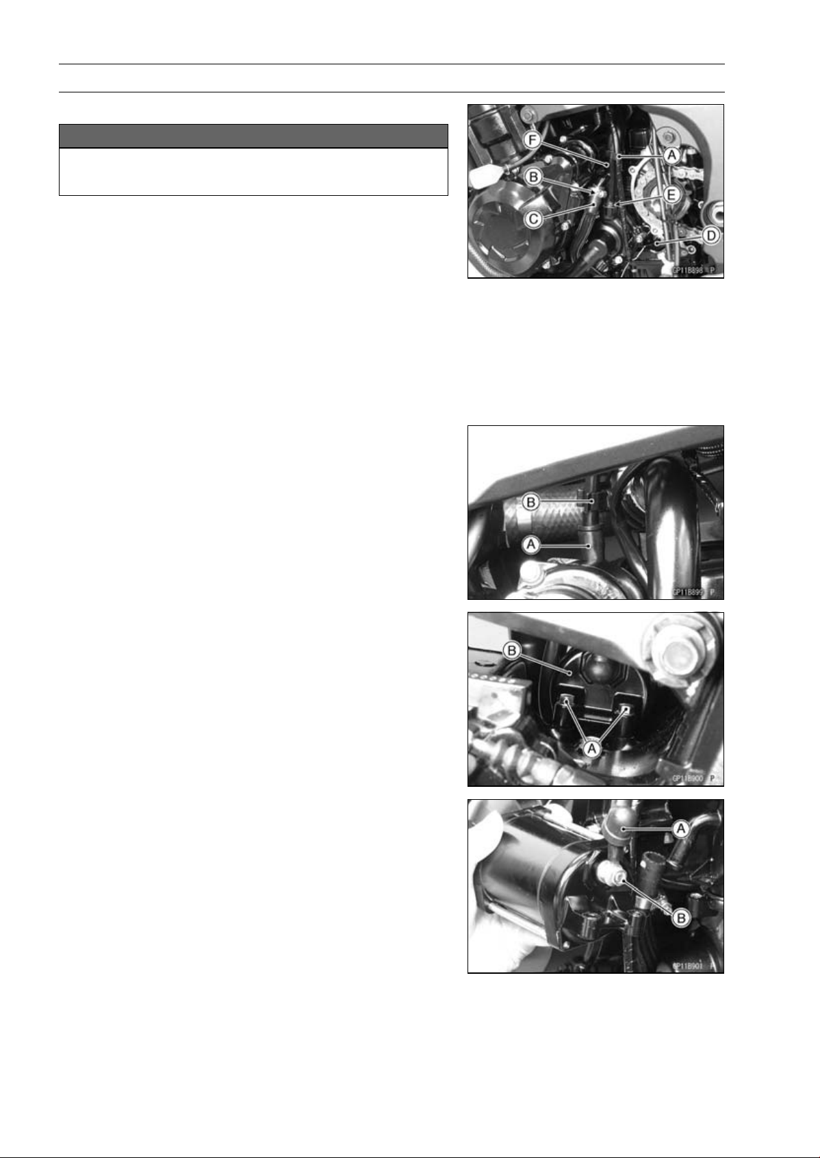
16-48 ELECTRICAL SYSTEM
Electric Starter System
Starter Motor Removal
NOTICE
Do not tap the starter motor shaft or body. Tapping
the shaft or body could damage the motor.
•
Drain the coolant (see Coolant Change in the Periodic
Maintenance chapter).
•
Remove:
Engine Sprocket Cover (see Engine Sprocket Cover Re-
moval in the Final Drive chapter)
Harness Holder [A]
•
Loosen the water hose clamp screw [B].
•
Remove:
Water Hose [C]
Neutral Switch Connector [D]
Water Pipe Bolt [E]
Water Pipe [F]
•
Remove the starter motor cable [A] from the cable holder
[B].
•
Remove the mounting bolts [A].
•
Pull out the starter motor [B] with the cable connected.
•
Slide the rubber cap [A].
•
Remove the starter motor cable terminal nut [B] and ca-
ble.
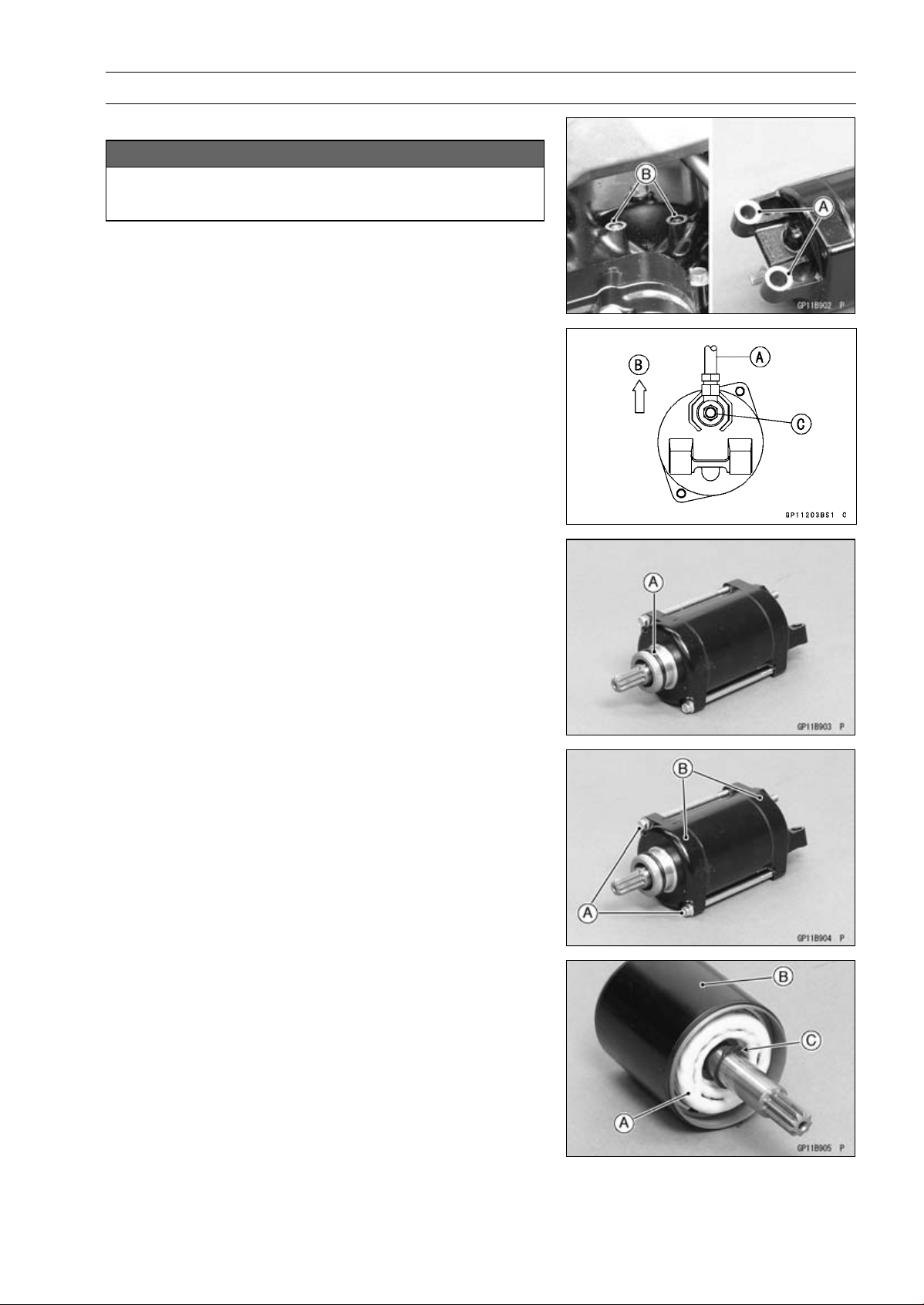
ELECTRICAL SYSTEM 16-49
Electric Starter System
Starter Motor Installation
NOTICE
Do not tap the starter motor shaft or body. Tapping
the shaft or body could damage the motor.
•
When installing the starter motor, clean the starter mo-
tor legs [A] and crankcase [B] where the starter motor is
grounded.
•
Install the starter motor cable [A] as shown.
[B] Upward
•
Tighten:
Torque - Starter Motor Cable Terminal Nut [C]: 5.9 N·m (0.60
kgf·m, 52 in·lb)
•
Slide back the rubber cap to the original position.
•
Replace the O-ring [A] with a new one.
•
Apply grease to the O-ring.
•
Tighten:
Torque - Starter Motor Mounting Bolts: 9.8 N·m (1.0 kgf·m,
87 in·lb)
•
Install the water hose and pipe (see Water Pump Instal-
lation in the Cooling System chapter).
Starter Motor Disassembly
•
Remove the starter motor (see Starter Motor Removal).
•
Take off the starter motor through bolts [A] and remove
the both end covers [B].
•
Pull out the armature [A] out of the yoke [B].
NOTE
○
Do not remove the circlip [C] from the shaft.
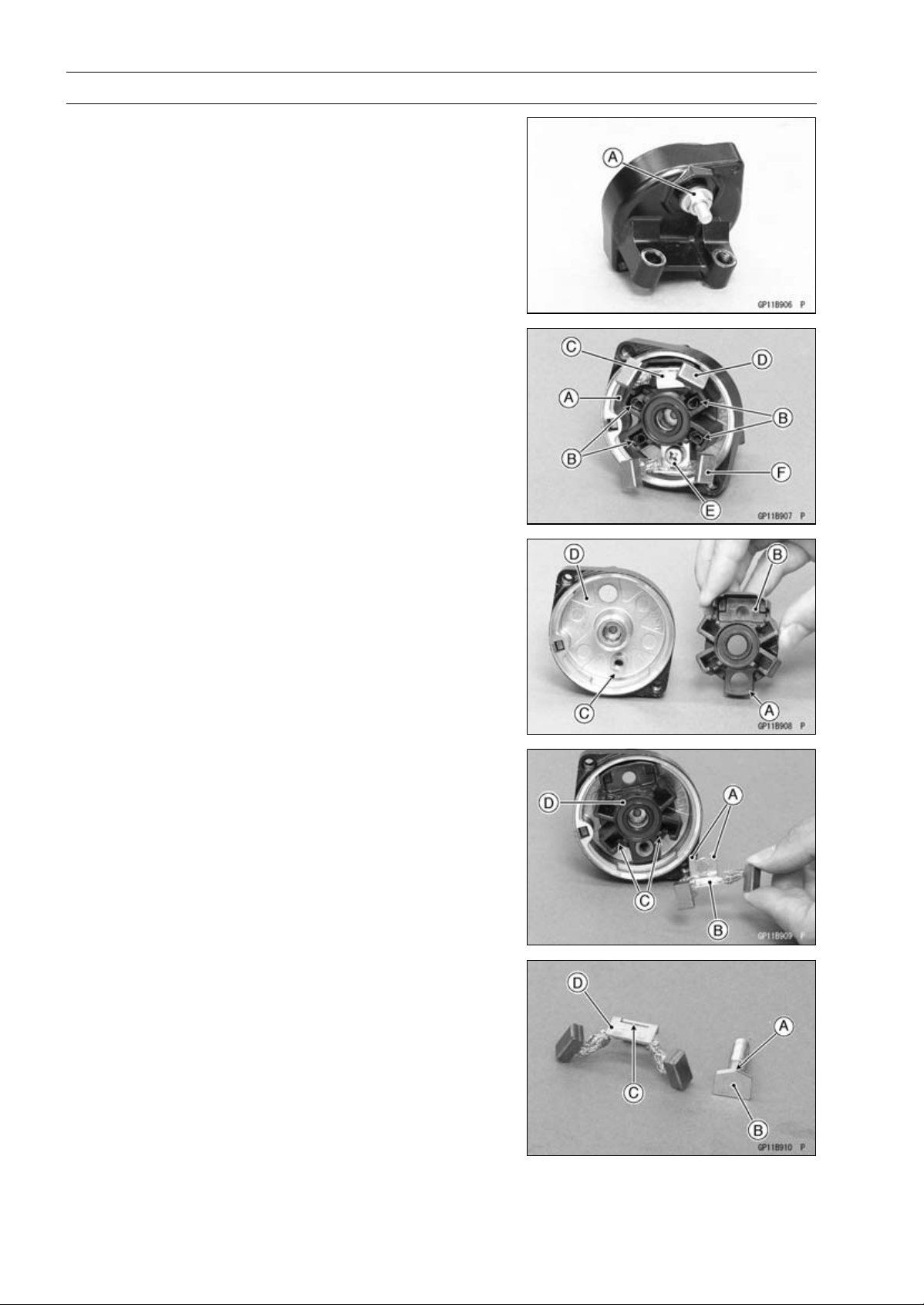
16-50 ELECTRICAL SYSTEM
Electric Starter System
•
Remove the starter motor terminal locknut [A].
•
Pull out the brushes from the brush holder [A].
•
Remove:
Brush Springs [B]
Starter Motor Terminal [C]
Positive Brush Assy [D]
Screw [E]
Negative Brush Assy [F]
Brush Holder
Starter Motor Assembly
•
Align the hole [A] of the brush holder [B] to the boss [C]
of the right-hand end cover [D].
•
Align the stoppers [A] of the negative brush assy [B] to
the guides [C] of the brush holder [D].
•
Tighten the screw securely.
•
Insert the jagged porition [A] on the starter motor terminal
[B] to the slit [C] on the positive brush assy [D].
•
Install the starter motor terminal to the brush holder.
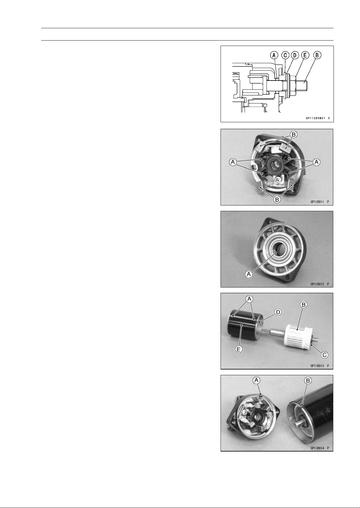
ELECTRICAL SYSTEM 16-51
Electric Starter System
•
Replace the O-ring [A] with a new one.
•
Install the following parts to the starter motor terminal [B].
New O-ring
Collar [C]
Washer [D]
Starter Motor Terminal Locknut [E]
○
Install the collar so that stepped side faces outward.
•
Tighten:
Torque - Starter Motor Terminal Locknut: 11 N·m (1.1
kgf·m, 97 in·lb)
•
Install the brush springs [A] and insert the brushes [B].
•
Apply thin coat of grease to the oil seal [A].
•
Replace the O-rings [A] with new ones.
•
Insert the armature [B] so that commutator side [C] faces
hollow side [D] of the yoke [E].
•
Align the stopper [A] and hollow [B] to assemble the yoke
and end cover.
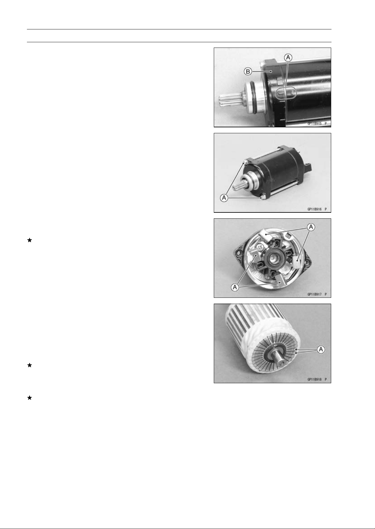
16-52 ELECTRICAL SYSTEM
Electric Starter System
•
Align the marks [A] to assemble the yoke and the end
cover [B].
•
Tighten:
Torque - Starter Motor Through Bolts [A]: 4.9 N·m (0.50
kgf·m, 43 in·lb)
Brush Inspection
•
Measure the length of each brushes [A].
If any is worn down to the service limit, replace the brush
assy.
Starter Motor Brush Length
Standard: 12 mm (0.47 in.)
Service Limit: 6.5 mm (0.26 in.)
Commutator Cleaning and Inspection
•
Clean the metallic debris off the between commutator
segments [A].
NOTE
○
Do not use emery or sand paper on the commutator.
•
Check the commutator for damage or abnormal wear.
Replace the starter motor with a new one if there is any
damage or wear.
•
Visually inspect the commutator segments for discol-
oration.
Replace the starter motor with a new one if discoloration
is noticed.
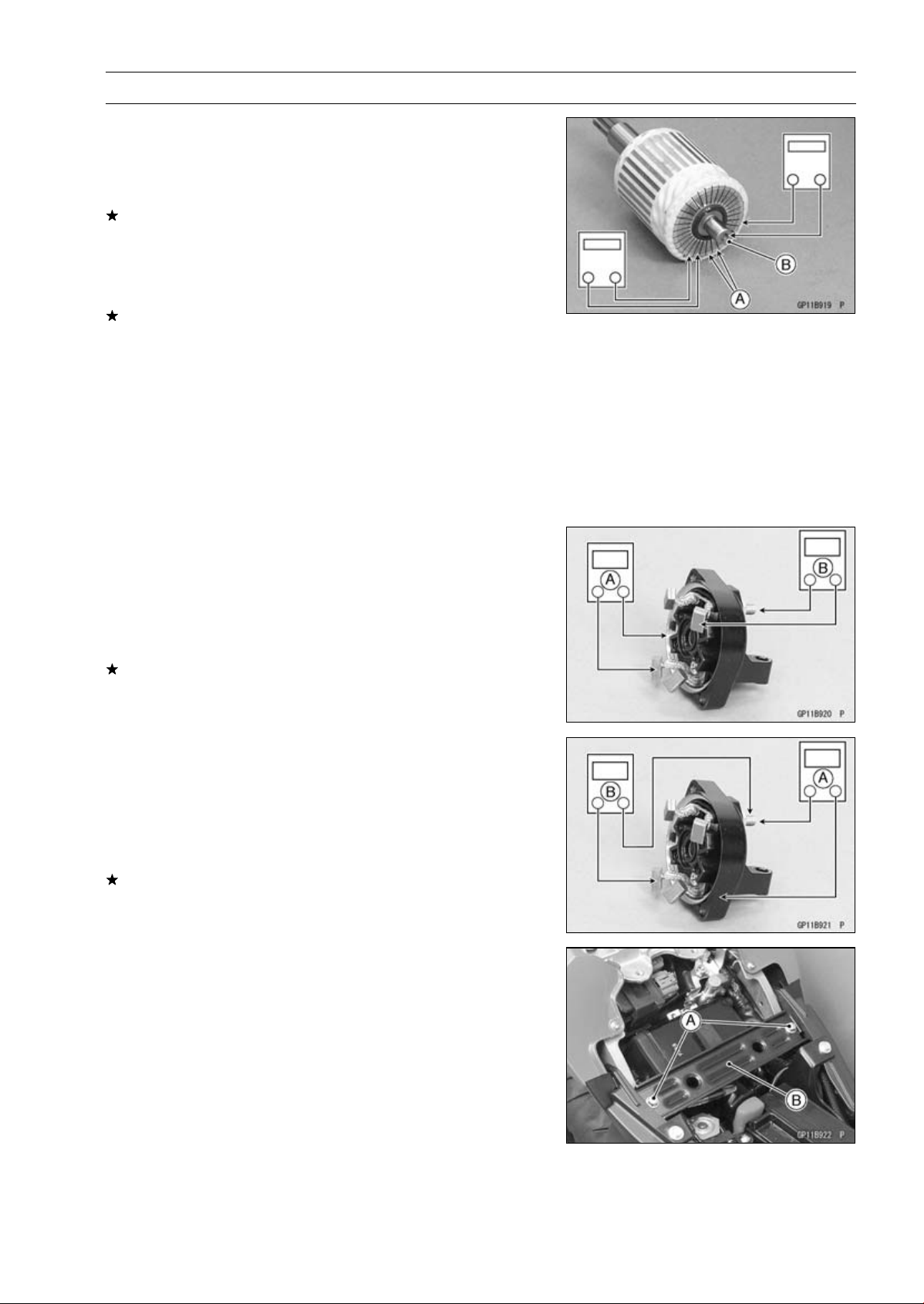
ELECTRICAL SYSTEM 16-53
Electric Starter System
Armature Inspection
•
Using the × 1 Ω hand tester range, measure the resis-
tance between any two commutator segments [A].
Special Tool - Hand Tester: 57001-1394
If there is a high resistance or no reading (∞) between any
two segments, a winding is open and the starter motor
must be replaced.
•
Using the highest hand tester range, measure the resis-
tance between the segments and the shaft [B].
If there is any reading at all, the armature has a short and
the starter motor must be replaced.
NOTE
○
Even if the foregoing checks show the armature to be
good, it may be defective in some manner not readily
detectable with the hand tester. If all other starter motor
and starter motor circuit components check good, but
the starter motor still does not turn over or only turns
over weakly, replace the starter motor with a new one.
Brush Lead Inspection
•
Using the × 1 Ω hand tester range, measure the resis-
tance as shown.
Right-hand End Cover and Negative Brushes [A]
Terminal Bolt and Positive Brushes [B]
Special Tool - Hand Tester: 57001-1394
If there is not close to zero ohms, the brush lead has an
open. Replace the brush plate assy.
Right-hand End Cover Inspection
•
Using the highest hand tester range, measure the resis-
tance as shown.
Terminal Bolt and Right-hand End Cover [A]
Terminal Bolt and Negative Brushes [B]
Special Tool - Hand Tester: 57001-1394
If there is any reading, the brush assy and/or terminal bolt
assy have a short. Replace the starter motor.
Starter Relay Inspection
•
Remove:
Battery Negative (–) Cable (see Battery Removal)
Front Seat Bracket Bolts [A]
Front Seat Bracket [B]
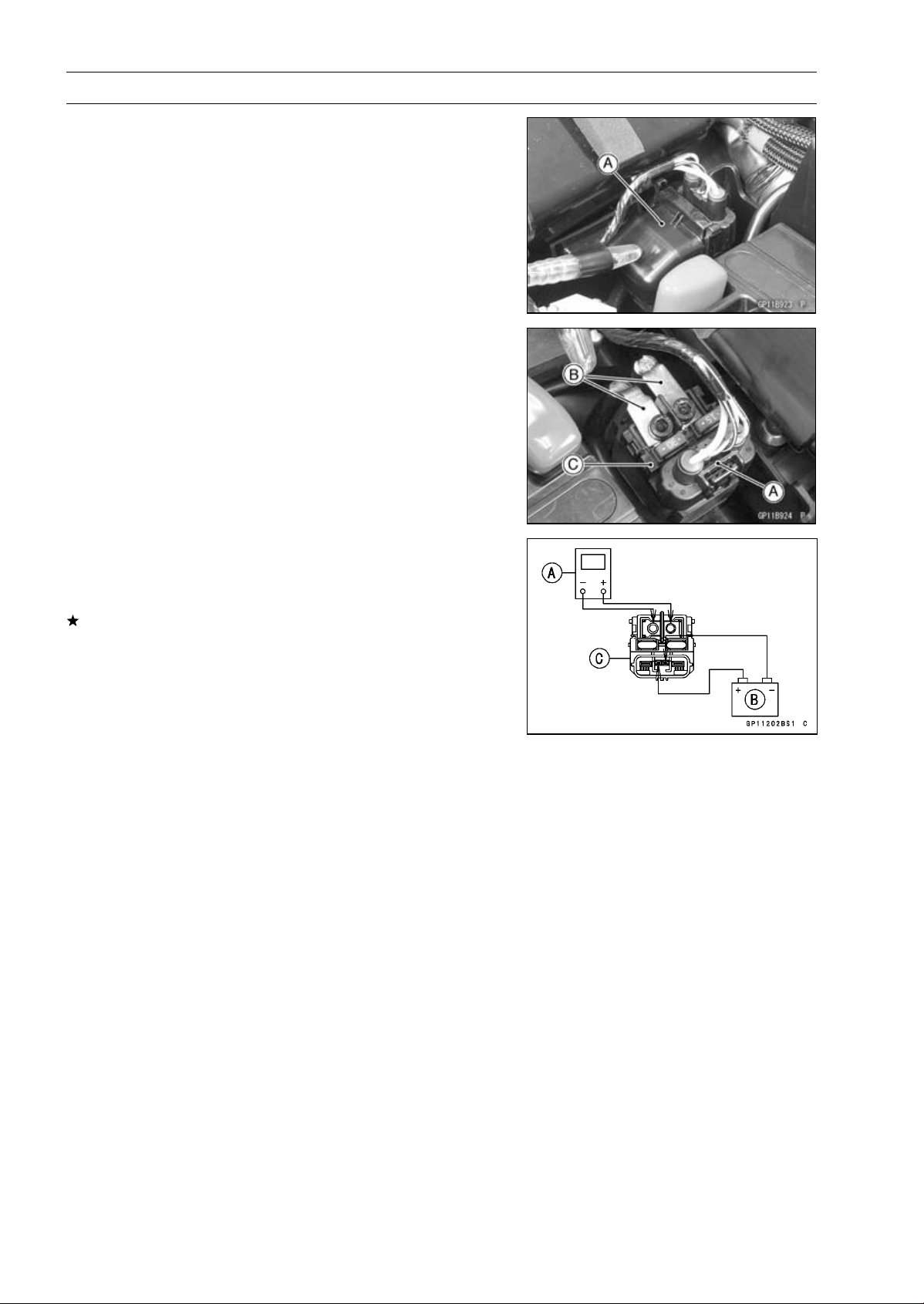
16-54 ELECTRICAL SYSTEM
Electric Starter System
•
Remove the cable terminal cover [A].
•
Disconnect:
Connector [A]
Cable Terminals [B]
•
Remove:
Starter Relay [C]
•
Connect the hand tester [A] and 12 V battery [B] to the
starter relay [C] as shown in the figure.
Special Tool - Hand Tester: 57001-1394
If the relay does not work as specified, the relay is defec-
tive. Replace the relay.
Testing Relay
Tester Range:
×1 range
Criteria: When battery is connected 0
When battery is disconnected
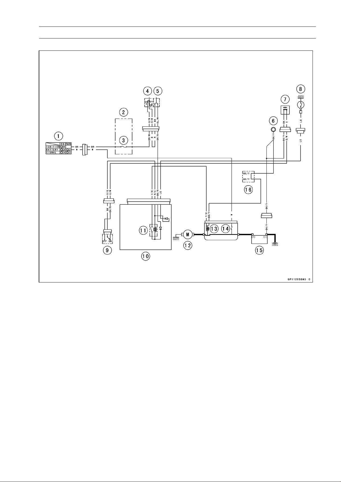
ELECTRICAL SYSTEM 16-55
Electric Starter System
Electric Starter Circuit
1. Ignition Switch
2. Fuse Box
3. Ignition Fuse 15 A
4. Engine Stop Switch
5. Starter Button
6. Frame Ground
7. Sidestand Switch
8. Neutral Switch
9. Starter Lockout Switch
10. Relay Box
11. Starter Circuit Relay
12. Starter Motor
13. Starter Relay
14. Main Fuse 30 A
15. Battery 12 V 8 Ah
16. Water-proof Joint B
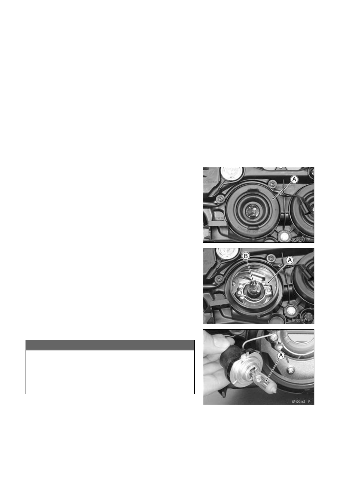
16-56 ELECTRICAL SYSTEM
Lighting System
This motorcycle adopt the daylight system and have a
headlight relay in the relay box. The headlight does not
go on when the ignition switch and the engine stop switch
are first turned on. The headlight comes on after the starter
button is released and stays on until the ignition switch is
turned off. The headlight will go out momentarily whenever
the starter button is pressed and come back on when the
button is released.
Headlight Beam Horizontal Adjustment
•
Refer to the Headlight Aiming Inspection in the Periodic
Maintenance chapter.
Headlight Beam Vertical Adjustment
•
Refer to the Headlight Aiming Inspection in the Periodic
Maintenance chapter.
Headlight Bulb Replacement
•
Remove:
Upper Fairing (see Upper Fairing Removal in the Frame
chapter)
Headlight Bulb Dust Cover [A]
•
Remove:
Hook [A]
Headlight Bulb [B]
•
Replace the headlight bulb.
NOTICE
When handling the quartz-halogen bulb [A], never
touch the glass portion with bare hands. Always
use a clean cloth. Oil contamination from hands or
dirty rags can reduce bulb life or cause the bulb to
explode.
NOTE
○
Clean off any contamination that inadvertently gets on
the bulb with alcohol or soap and water solution.
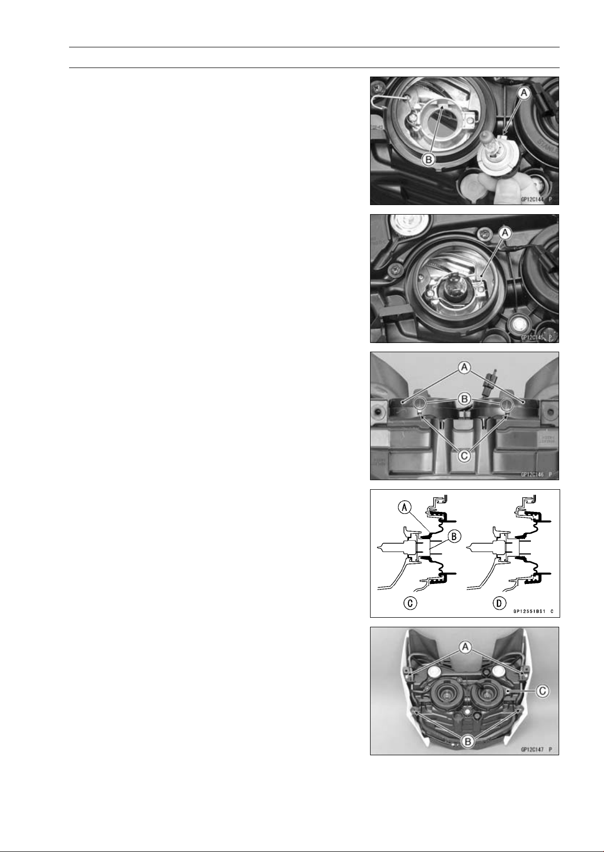
ELECTRICAL SYSTEM 16-57
Lighting System
•
Fit the projection [A] of the bulb in the hollow [B] of the
headlight.
•
Install the hook [A].
•
Install the dust covers [A] so that align the arrow marks
[B] and slits [C] on the headlight body.
•
Be sure to fit the dust cover [A] onto the bulb [B] firmly as
shown in the figure.
Good [C]
Bad [D]
•
After installation, adjust the headlight aim (see Headlight
Aiming Inspection in the Periodic Maintenance chapter).
Headlight Removal/Installation
•
Remove:
Upper Fairing (see Upper Fairing Removal in the Frame
chapter)
Bolts [A]
QuickRivets[B]
Headlight Assy [C]
•
Installation is the reverse of removal.

16-58 ELECTRICAL SYSTEM
Lighting System
City Light Bulb Replacement
•
Remove the headlight (see Headlight Removal).
•
Pull out the socket [A] and remove it with the bulb.
•
Pull out the bulb [A] straight from the socket.
NOTICE
Do not turn the bulb. Pull the bulb out to prevent
damage to the bulb. Do not use bulb rated for
greater wattage then the specified valve.
•
Replace the bulb with a new one.
•
Install the socket securely.
Tail/Brake Light (LED) Removal
•
Remove:
Seat Cover (see Seat Cover Removal in the Frame
chapter)
Tail/Brake Light Mounting Bolts [A]
•
Disconnect the tail/brake light lead connector [A] to re-
move the tail/brake light (LED).
Tail/Brake Light (LED) Installation
•
Installation is the reverse of removal.
•
Tighten the tail/brake light mounting bolts securely.
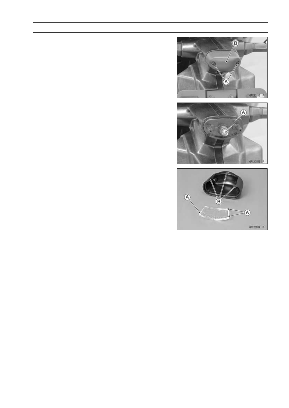
ELECTRICAL SYSTEM 16-59
Lighting System
License Plate Light Bulb Replacement
•
Remove:
Screws [A]
License Plate Light Cover [B] and Lens
•
Pulloutthebulb[A].
•
Replace the bulb with a new one.
•
Insert the new bulb into the socket.
•
Fit the projections [A] on the lens to the cover grooves [B].
•
Tighten the license plate light cover screws.
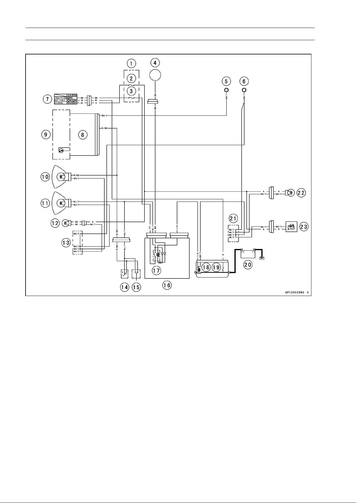
16-60 ELECTRICAL SYSTEM
Lighting System
Headlight/Tail Light Circuit
1. Fuse Box
2. Turn Signal Relay Fuse 10 A
3. Headlight Fuse 10 A
4. Alternator
5. Meter Ground
6. Frame Ground
7. Ignition Switch
8. Meter Unit
9. High Beam Indicator Light (LED)
10. Headlight (High) 12 V 55 W
11. Headlight (Low) 12 V 55 W
12. City Light 12 V 5 W
13. Water-proof Joint A
14. Dimmer Switch
15. Passing Button (Other than US, CA and CAL
Models)
16. Relay Box
17. Headlight Circuit Relay
18. Starter Relay
19. Main Fuse 30 A
20. Battery 12 V 8 Ah
21. Water-proof Joint B
22. License Plate Light 12 V 5 W
23. Tail/Brake Light (LED)
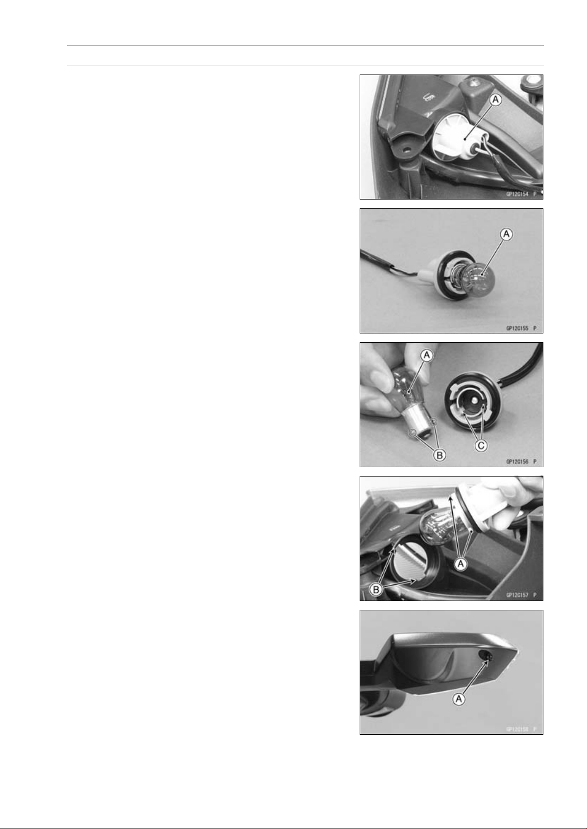
ELECTRICAL SYSTEM 16-61
Lighting System
Turn Signal Light Bulb Replacement
Front Turn Signal Light
•
Remove:
Center Fairings (see Center Fairing Removal in the
Frame chapter)
Inner Fairings (see Inner Fairing Removal in the Frame
chapter)
•
Turn the socket [A] counterclockwise and pull out the
socket together with the bulb.
•
Push and turn the bulb [A] counterclockwise and remove
it.
•
Insert the new bulb [A] by aligning its upper and lower pins
[B] with the upper and lower grooves [C] in the socket, and
turn the bulb clockwise.
○
Turn the bulb about 15°.
•
Pushing the socket and turn it clockwise.
○
Fit the projections [A] of the socket into the grooves [B] of
the turn signal light.
•
Install the removed parts (see appropriate chapters).
Rear Turn Signal Light
•
Unscrew the screw [A] and remove the lens.
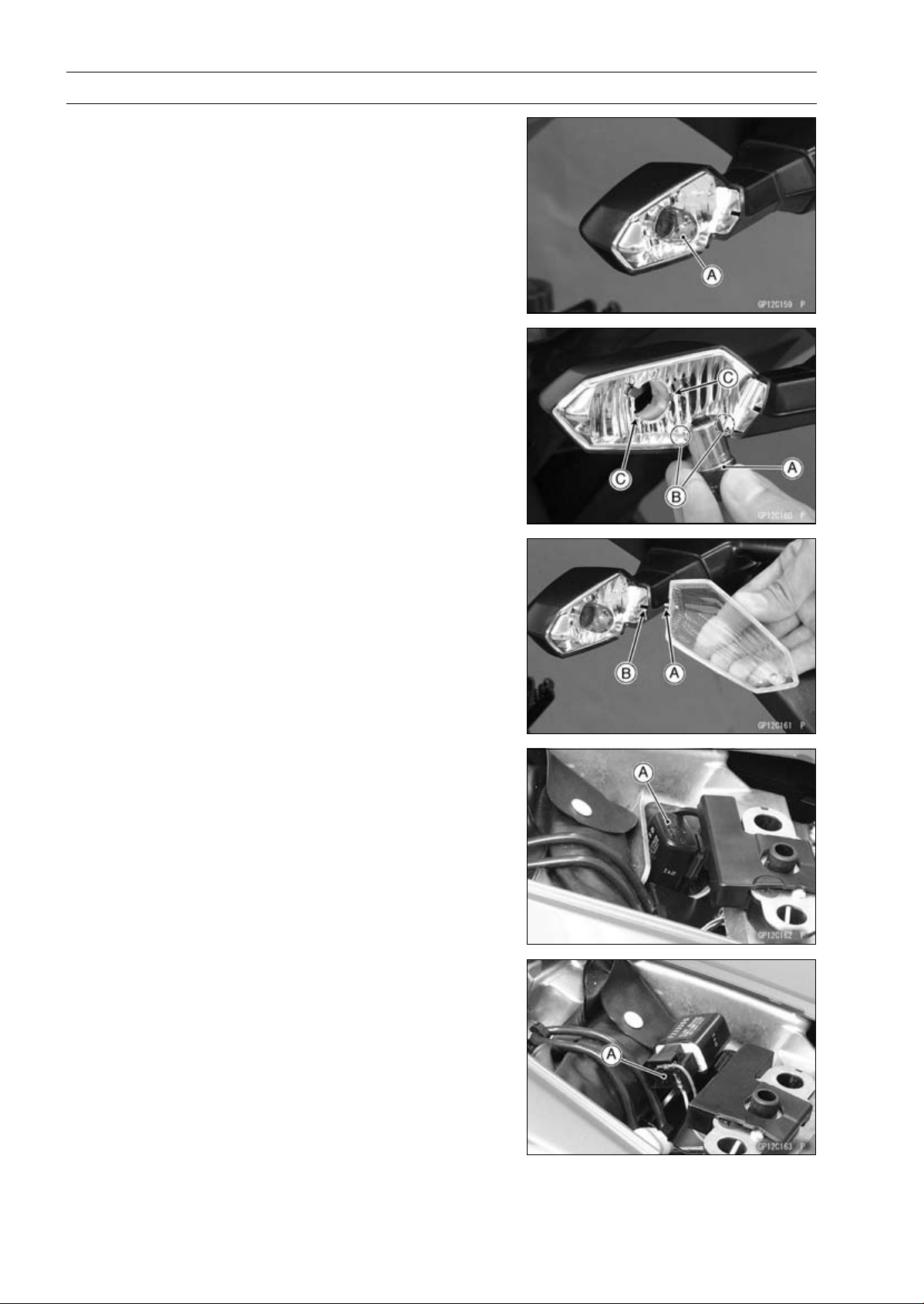
16-62 ELECTRICAL SYSTEM
Lighting System
•
Push and turn the bulb [A] counterclockwise and remove
it.
•
Insert the new bulb [A] by aligning its upper and lower pins
[B] with the upper and lower grooves [C] in the socket, and
turn the bulb clockwise.
○
Turn the bulb about 15°.
•
Fit the projection [A] on the lens to the groove [B] on the
socket.
•
Tighten the screw.
Turn Signal Relay Inspection
•
Remove:
Rear Seat (see Rear Seat Removal in the Frame chap-
ter)
•
Pull up the turn signal relay [A].
•
Disconnect the turn signal relay connector [A].
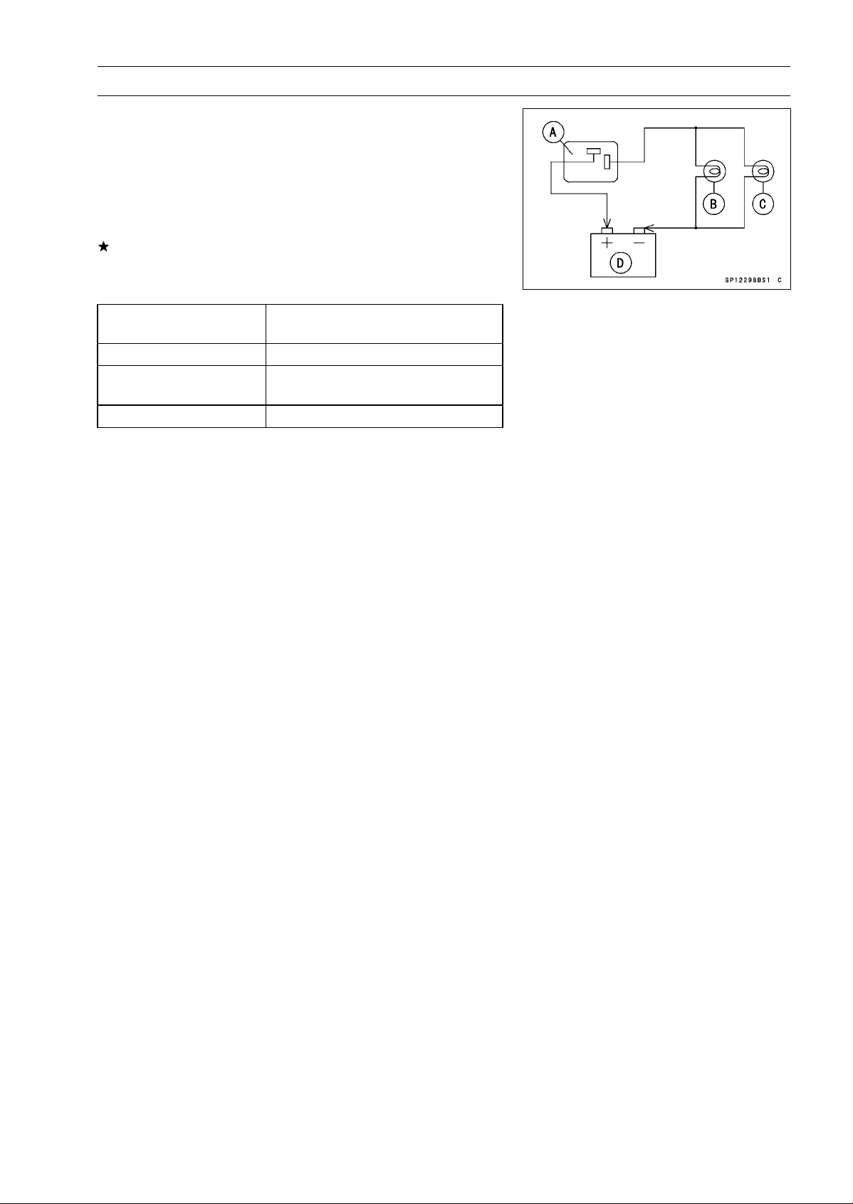
ELECTRICAL SYSTEM 16-63
Lighting System
•
Connect one 12 V battery and turn signal lights as indi-
cated in the figure, and count how may times the lights
flash for one minute.
Turn Signal Relay [A]
Turn Signal Light 21 W [B]
Turn Signal Light 10 W [C]
12 V Battery [D]
If the lights do not flash as specified, replace the turn sig-
nal relay.
Testing Turn Signal Relay
Connections of Turn
Signal Lights
Flashing Times (c/m)*
[B] (21 W) and [C] (10 W)
75 ∼ 95
[B] (21 W)
[B] (21 W) Light Stays on or flashing
times decrease more than 15.
[C] (10 W) [C] (10 W) Light Stays on.
*: Cycle(s) per minute
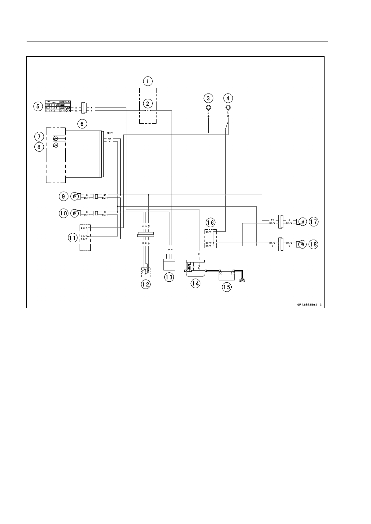
16-64 ELECTRICAL SYSTEM
Lighting System
Turn Signal Light Circuit
1. Fuse Box
2. Turn Signal Relay Fuse 10 A
3. Meter Ground
4. Frame Ground
5. Ignition Switch
6. Meter Unit
7. Right Turn Signal Indicator Light (LED)
8. Left Turn Signal Indicator Light (LED)
9. Front Right Turn Signal Light 12 V 21 W
10. Front Left Turn Signal Light 12 V 21 W
11. Water-proof Joint A
12. Turn Signal Switch
13. Turn Signal Relay
14. Main Fuse 30 A
15. Battery 12 V 8 Ah
16. Water-proof Joint B
17. Rear Right Turn Signal Light 12 V 10 W
18. Rear Left Turn Signal Light 12 V 10 W
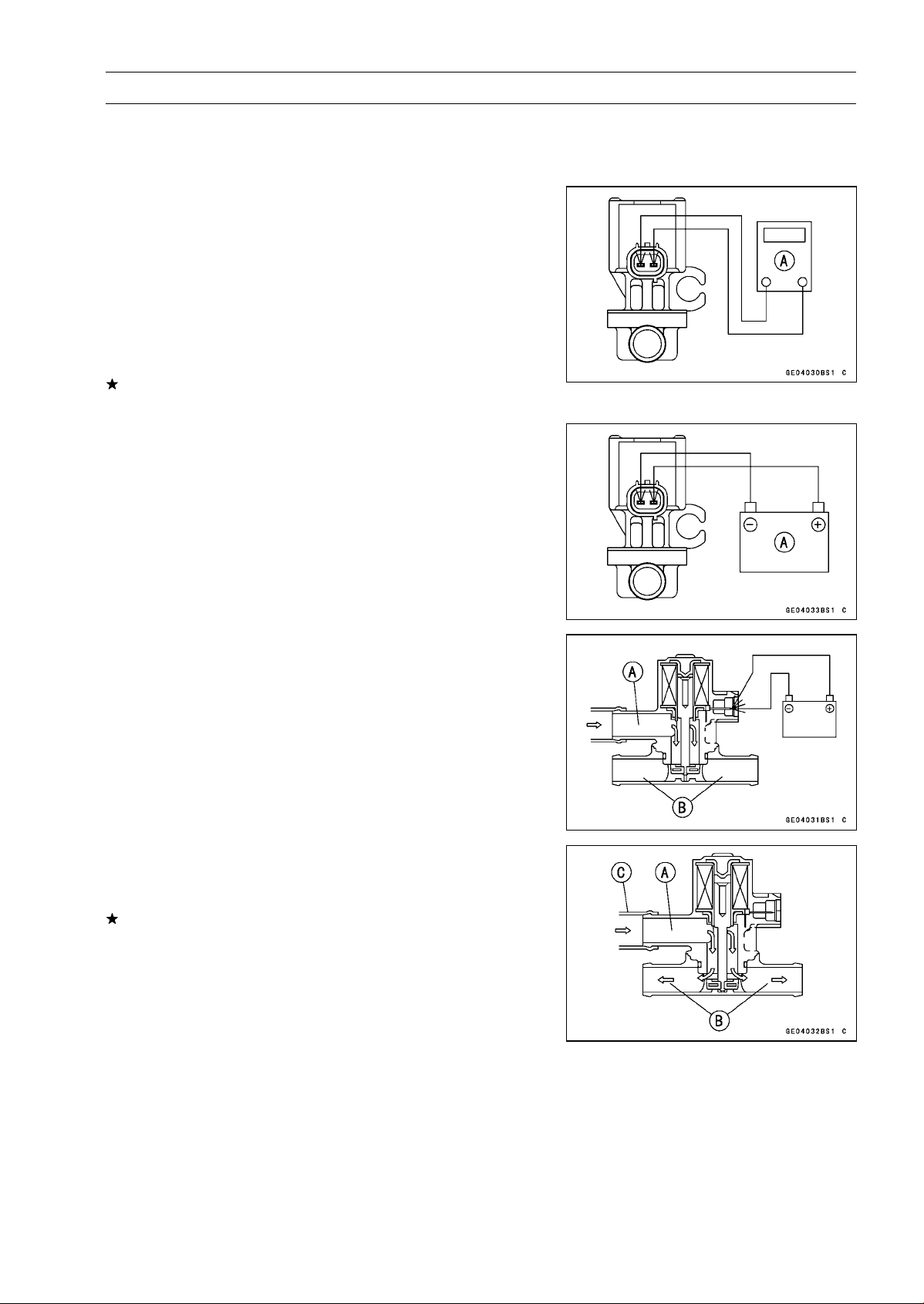
ELECTRICAL SYSTEM 16-65
Air Switching Valve
Air Switching Valve Operation Test
•
Refer to the Air Suction System Damage Inspection in the
Periodic Maintenance chapter.
Air Switching Valve Unit Test
•
Remove the air switching valve (see Air Switching Valve
Removal in the Engine Top End chapter).
•
Set the hand tester [A] to the × 1 Ω range and connect it
to the air switching valve terminals as shown in the figure.
Special Tool - Hand Tester: 57001-1394
Air Switching Valve Resistance
Standard: 18
∼ 22 at 20°C (68°F)
If the tester does not read as specified value, replace it
with a new one.
•
Connect the 12 V battery [A] to the air switching valve
terminals as shown in the figure.
•
Blow the air to the intake air duct [A], and make sure does
not flow the blown air from the outlet air duct [B].
•
Disconnect the 12 V battery.
•
Blow the air to the intake air duct [A] again, and make sure
flow the blown air from the outlet air duct [B].
If the air switching valve does not operate as described,
replace it with a new one.
NOTE
○
To check air flow through the air switching valve, just
blow through the air switching valve hose (intake side)
[C].
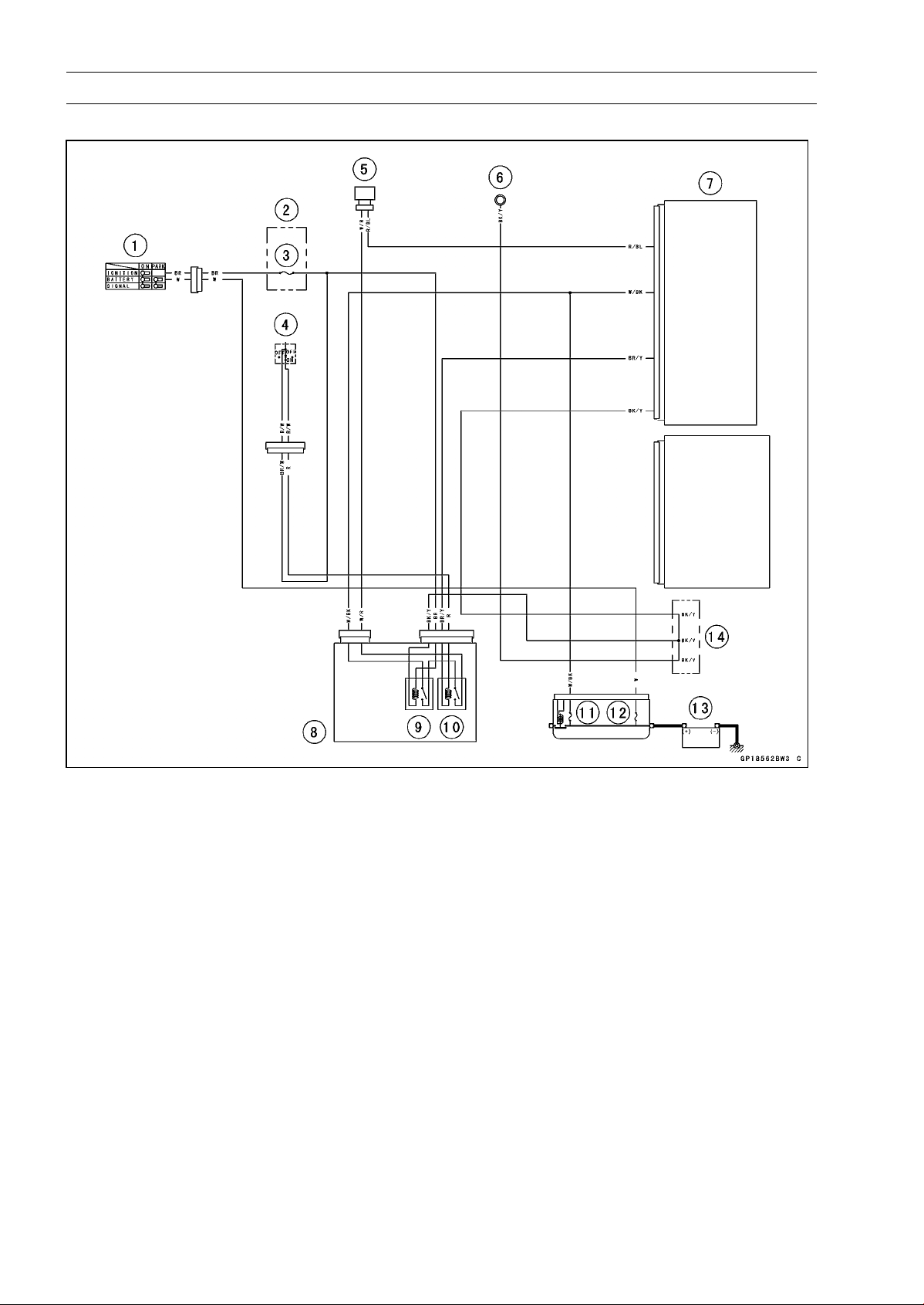
16-66 ELECTRICAL SYSTEM
Air Switching Valve
Air Switching Valve Circuit
1. Ignition Switch
2. Fuse Box
3. Ignition Fuse 15 A
4. Engine Stop Switch
5. Air Switching Valve
6. Meter Ground
7. ECU
8. Relay Box
9. ECU Main Relay
10. Fuel Pump Relay
11.FIFuse15A
12. Main Fuse 30 A
13. Battery 12 V 8 Ah
14. Water-proof Joint C
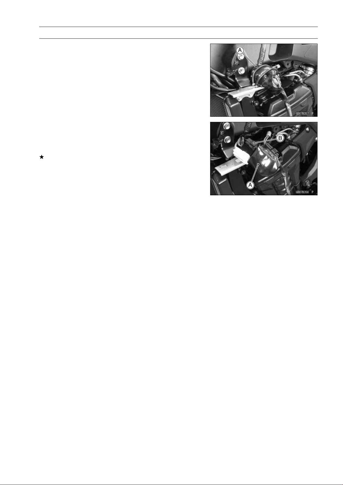
ELECTRICAL SYSTEM 16-67
Radiator Fan System
Fan Motor Inspection
•
Remove the left center fairing (see Center Fairing Re-
moval in the Frame chapter).
•
Remove the band [A].
•
Slide the dust cover [A].
•
Disconnect the connector [B].
•
Using an auxiliary leads, supply battery power to the fan
motor.
If the fan does not rotate, the fan motor is defective and
must be replaced.
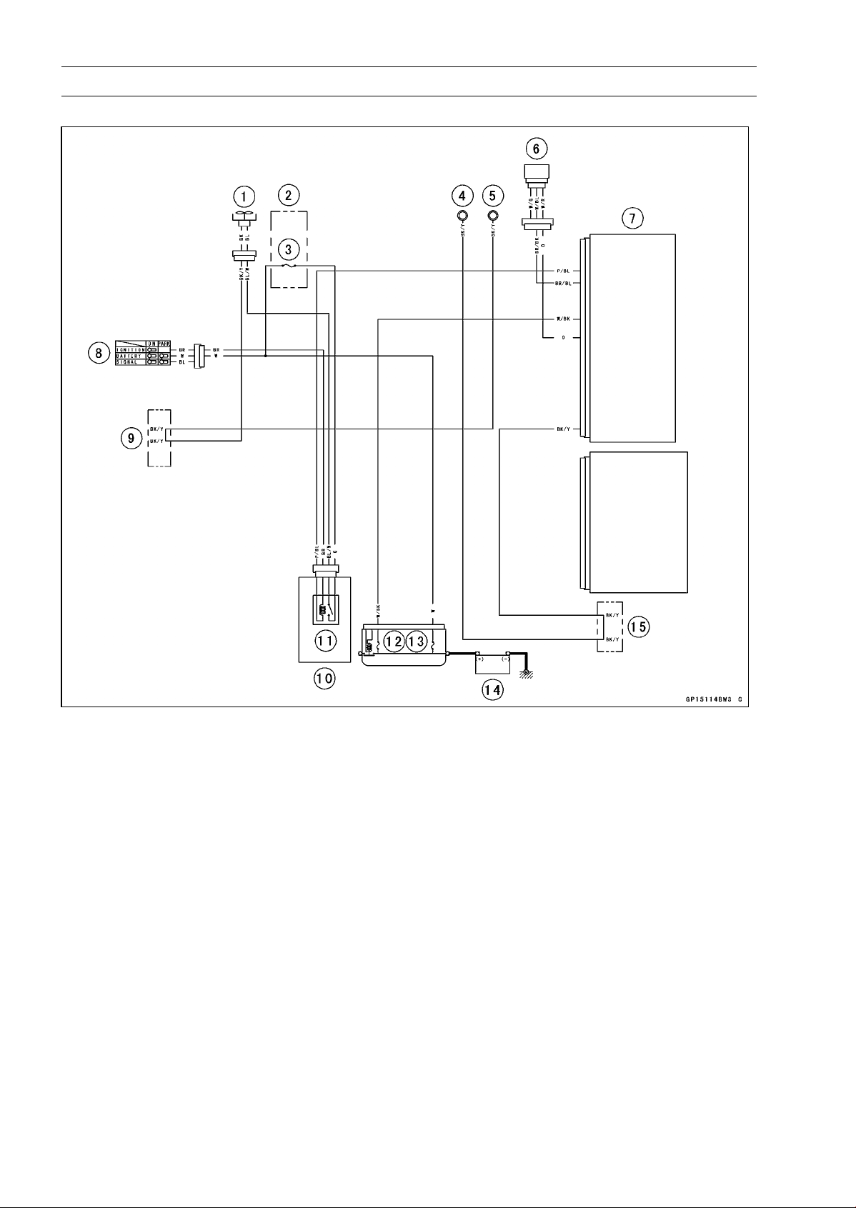
16-68 ELECTRICAL SYSTEM
Radiator Fan System
Radiator Fan Circuit
1. Radiator Fan Motor
2. Fuse Box
3. Fan Fuse 15 A
4. Meter Gruond
5. Frame Ground
6. Water Temperature Sensor
7. ECU
8. Ignition Switch
9. Water-proof Joint A
10. Relay Box
11. Radiator Fan Relay
12. FI Fuse 15 A
13. Main Fuse 30 A
14. Battery 12 V 8 Ah
15. Water-proof Joint C
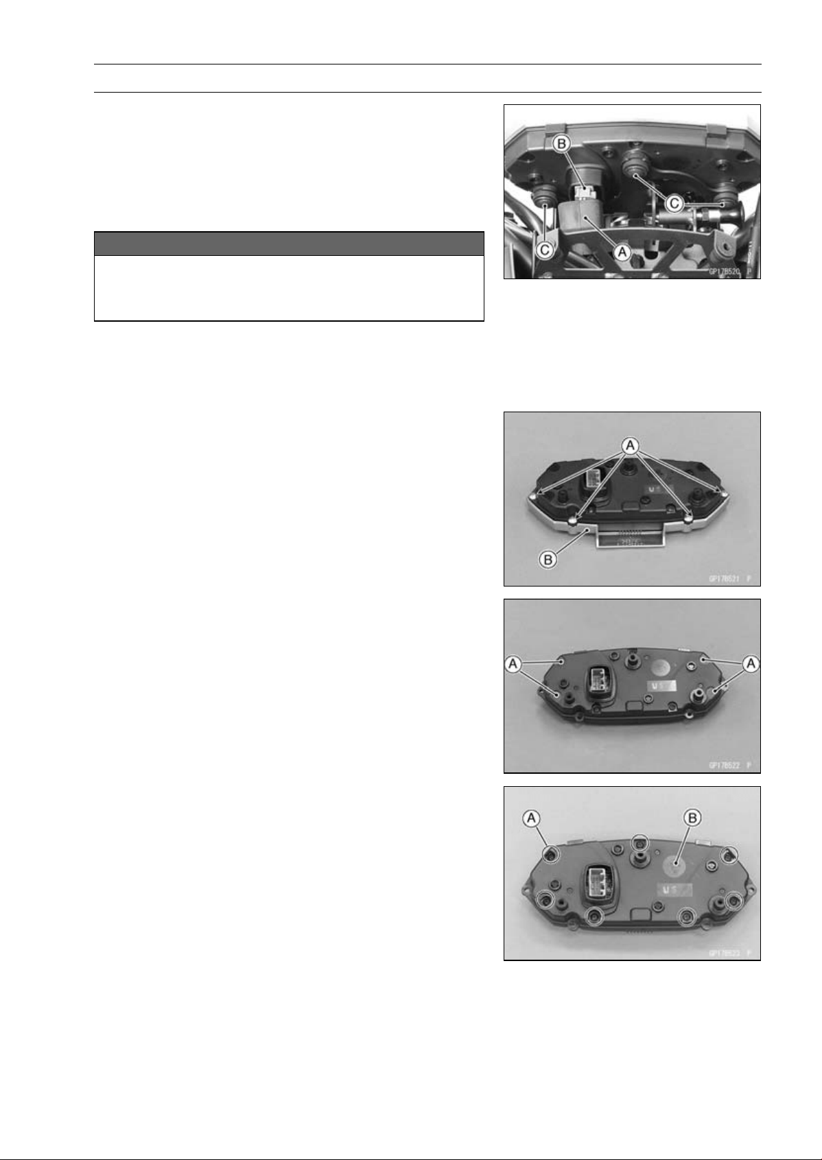
ELECTRICAL SYSTEM 16-69
Meter, Gauge, Indicator Unit
Meter Unit Removal/Installation
•
Remove:
Upper Fairing (see Upper Fairing Removal in the Frame
chapter)
•
Slide the dust cover [A] and remove the connector [B].
•
Remove the meter unit by taking off the mounting screws
[C] with the washers.
NOTICE
Place the meter unit so that the face is up. If a meter
unit is left upside down or sideways for any length
of time, it will malfunction.
•
Installation is the reverse of removal.
•
Tighten:
Torque - Meter Unit Mounting Screws: 1.2 N·m (0.12 kgf·m,
11 in·lb)
Meter Unit Disassembly
•
Remove:
Meter Unit (see Meter Unit Removal/Installation)
Screws [A]
Outer Meter Cover [B]
•
Pry the caps [A] to remove them.
•
Remove:
Screws [A]
Lower Meter Cover [B]
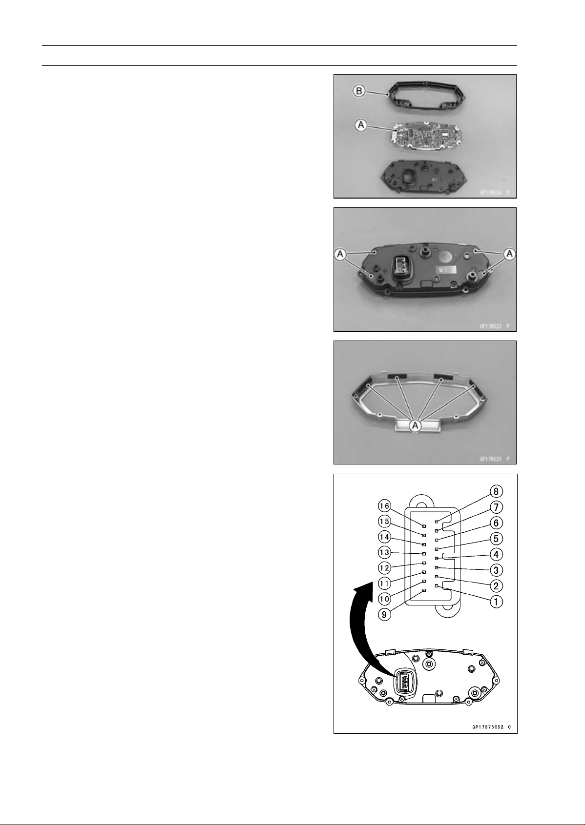
16-70 ELECTRICAL SYSTEM
Meter, Gauge, Indicator Unit
•
Separate the meter assembly [A] and upper meter cover
[B].
Meter Unit Assembly
•
Assembly the following parts.
Upper Meter Cover
Meter Assembly
Lower Meter Cover
•
Tighten the meter assembly screws.
•
Replace the caps [A] with new ones, and put them.
•
Be sure to install the pads [A].
•
Install the outer meter cover and tighten the screws se-
curely.
Meter Unit Inspection
•
Remove the meter unit [A] (see Meter Unit Removal).
[1] Battery (+)
[2] Ignition
[3] Ground (–)
[4] Speed Sensor Supply Voltage
[5] Speed Sensor Signal
[6] Tachometer Signal
[7] Warning Indicator Light (LED) (Oil Pressure Warning)
(–)
[8] Water Temperature Sensor (–)
[9] ECU Communication Signal
[10] ABS Indicator Light (LED) (–) (Equipped Models)
[11] Neutral Indicator Light (LED) (–)
[12] Left Turn Signal indicator Light (LED) (+)
[13] Right Turn Signal indicator Light (LED) (+)
[14] High Beam Indicator Light (LED) (+)
[15] Unused
[16] Fuel Level Gauge (–)
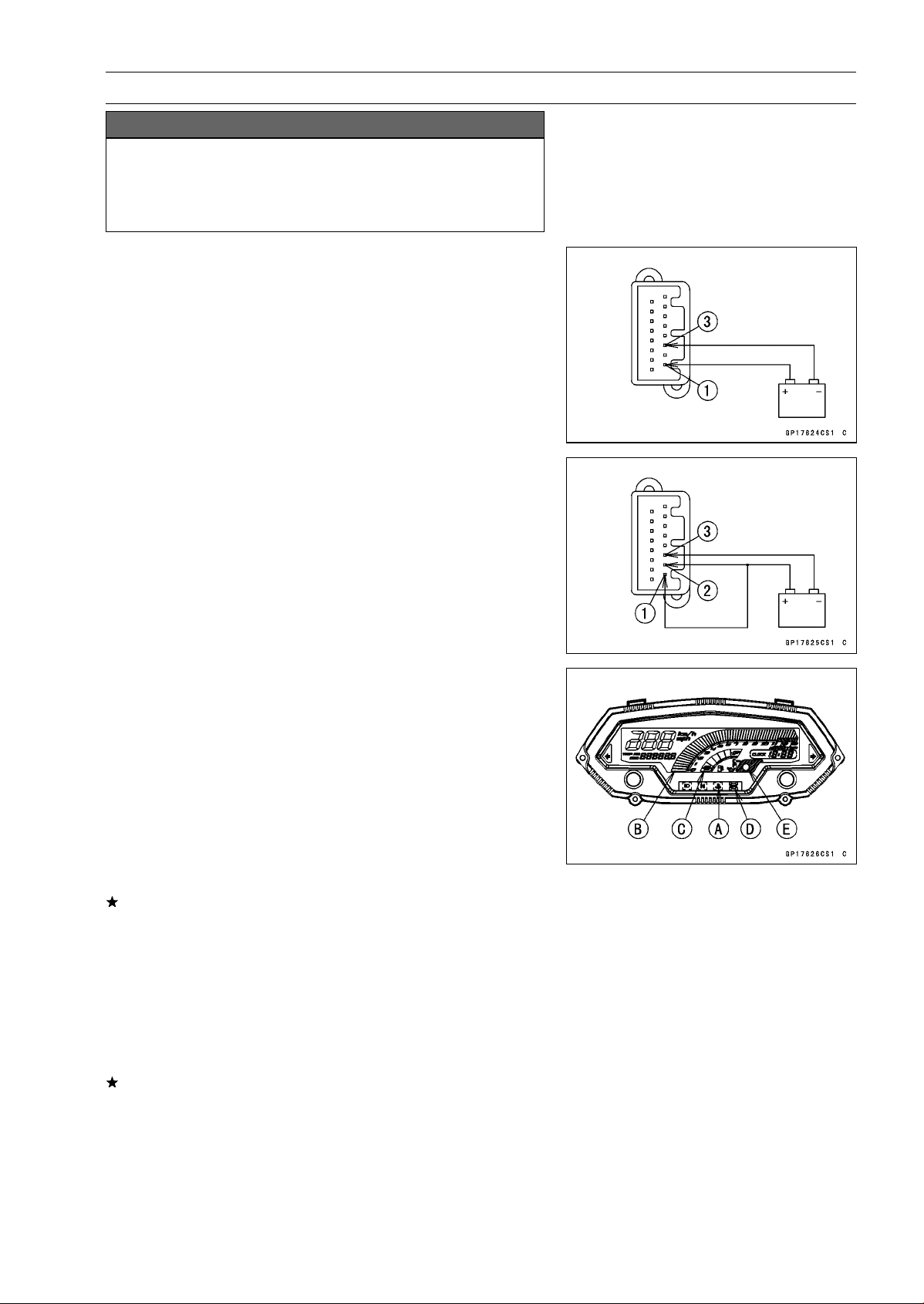
ELECTRICAL SYSTEM 16-71
Meter, Gauge, Indicator Unit
NOTICE
Do not drop the meter unit. Place the meter unit so
that it faces upward. If the meter assembly is left up-
side down or sideways for a long time or dropped,
it will malfunction. Do not short each terminals.
Liquid Crystal Display (LCD) Segments Check
•
Using the insulated auxiliary leads, connect the 12 V bat-
tery to the meter unit connector as follows.
○
Connect the battery positive terminal to the terminal [1].
○
Connect the battery negative terminal to the terminal [3].
•
Connect the terminal [2] to the terminal [1].
•
When the terminals are connected, the meter unit dis-
plays the following.
○
The water temperature warning indicator light (LED) [A]
goes on for 2 seconds.
○
The tachometer [B] and the fuel level gauge [C] momen-
tarily goes from the minimum to the maximum, then goes
back from the maximum to the minimum reading.
○
The speedometer and the odometer segments appear
from left, then disappear from left.
○
After the above indicaiton, all the LCD segments appear
for about 0.5 second.
If the LCD segments do not appear, replace the meter
assembly.
○
For models equipped with an ABS, the ABS indicator light
(LED) [D] goes on.
•
Disconnect the terminal [2].
○
All the LCD segments disappear.
○
For models equipped with an immobilizer system, the
warning indicator light (LED) [E] starts flashing (see
A
bstract section in the Immobilizer System).
If the segments do not disappear, replace the meter as-
sembly.
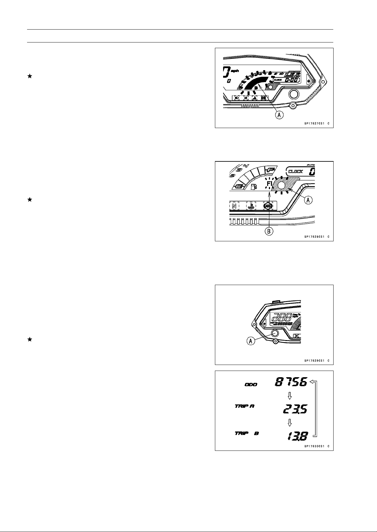
16-72 ELECTRICAL SYSTEM
Meter, Gauge, Indicator Unit
•
Connect the terminal [2] to the terminal [1] again.
○
About 3 seconds after, the all fuel level gauge segments
starts flashing [A].
If the fuel level gauge does not flash, replace the meter
assembly.
NOTE
○
This meter unit has a failure detection function (for open
or short) of the fuel level gauge. When the fuel level
gauge is open or short, the meter unit alerts the rider by
the all fuel level gauge segments flashes in the display.
○
If the failure detection function operates with the meter
unit installed on the motorcycle, inspect the fuel level
gauge (see Fuel Level Gauge Inspection) and wiring.
○
About 10 seconds after, the warning indicator light (LED)
[A] blinks and the FI warning symbol [B] appears in the
display.
○
The FI warning symbol is blinking.
If the warning indicator light (LED) does not blink and/or
the FI warning symbol does not appear, replace the meter
assembly.
NOTE
○
This meter unit has a failure detection function of the
ECU communication. When the ECU communication
error was detected, the meter unit alerts the rider by the
warning indicator light (LED) blinks and the FI warning
symbol appears in the display (see ECU Communica-
tion Line Inspection in the Fuel System (DFI) chapter).
Left and Right Button Operation Check
•
Connect the 12 V battery and terminals in the same man-
ner as specified in the “Liquid Crystal Display (LCD) Seg-
ments Check”.
•
Check that the display changes to the ODO, TRIP A and
TRIP B displays each time the left button [A] is pressed.
If the display function does not work, replace the meter
assembly.
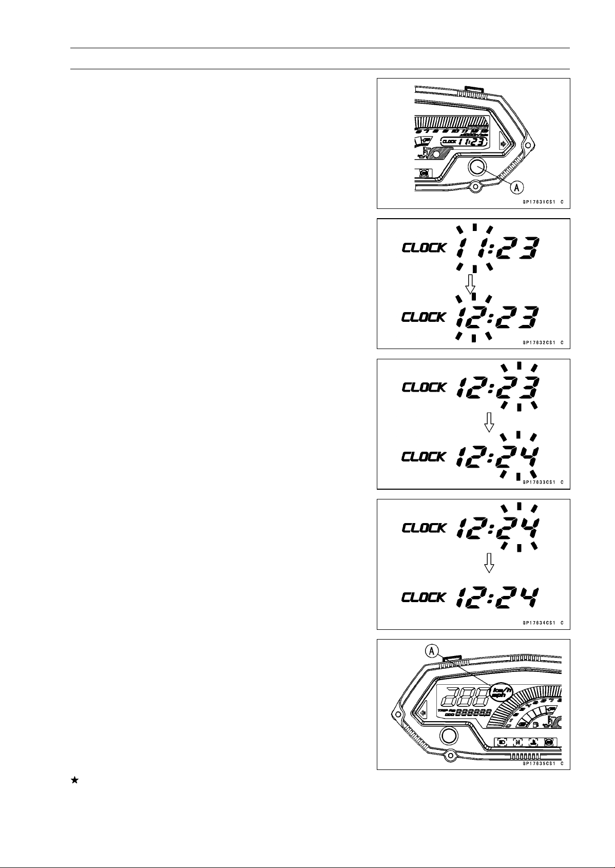
ELECTRICAL SYSTEM 16-73
Meter, Gauge, Indicator Unit
•
Indicate the ODO mode.
•
Check that when the right button [A] in ODO mode is
pushed for more than 2 seconds, the meter display turns
to the clock set mode.
○
Both the hour and minute display start flashing.
•
In the HOUR/MINUTE setting mode, press the right but-
ton again to effect the HOUR setting mode.
○
The hour display flashes on the display.
•
Press the left button to set the hour.
•
In the HOUR setting mode, press the right button to effect
the MINUTE setting mode.
○
The minute display flashes on the display.
•
Press the left button to set the minute.
•
In the MINUTE setting mode, press the right button to
return to the HOUR/MINUTE setting mode.
•
Press the left button to complete the time setting process.
○
The clock starts counting the seconds as soon as the left
button is pressed.
•
Indicate the ODO mode.
•
Check that the display [A] changes to the mile and km
display each time by pushing the right button while left
button pushed in.
NOTE
○
Mile/km display can alternate between mile and km
modes in the digital meter. Make sure that km or mile
according to local regulations is correctly displayed
before riding.
If the display function does not work and adjust, replace
the meter assembly.
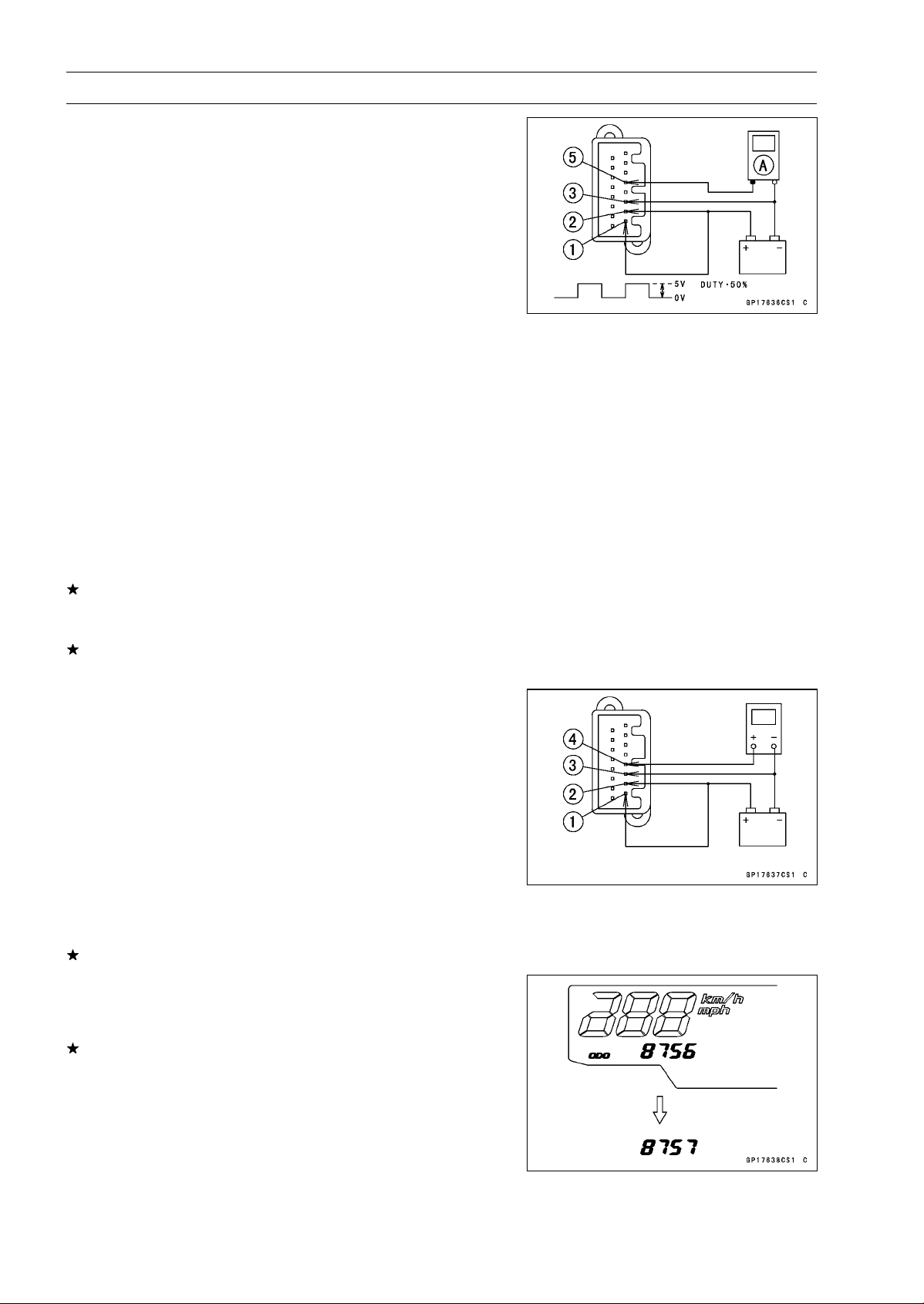
16-74 ELECTRICAL SYSTEM
Meter, Gauge, Indicator Unit
Speedometer Check
•
Connect the 12 V battery and terminals in the same man-
ner as specified in the “Liquid Crystal Display (LCD) Seg-
ments Check”.
•
The speed equivalent to the input frequency is indicated in
the oscillator [A], if the square wave (illustrated as shown)
would be input into the terminal [5].
○
Indicates approximately 60 mph in case the input fre-
quency would be approximately 311.5 Hz.
○
Indicates approximately 60 km/h in case the input fre-
quency would be approximately 194.7 Hz.
NOTE
○
The input frequency of the oscillator adds the integrated
value of the odometer.
○
The integrated value of the odometer cannot be reset.
•
If the oscillator is not available, the speedometer can be
checked as follows.
○
Install the meter unit.
○
Raise the rear wheel off the ground with stand.
○
Turn on the ignition switch.
○
Rotate the rear wheel by hand.
○
Check that the speedometer shows the speed.
If the speedometer does not work, check the speed sen-
sor (see Speed Sensor Input/Output Voltage Inspection
in the Fuel System (DFI) chapter).
If the speed sensor is normal, check the speed sensor
power source.
Speed Sensor Power Supply Check
•
Connect the 12 V battery and terminals in the same man-
ner as specified in the “Liquid Crystal Display (LCD) Seg-
ments Check”.
•
Set the hand tester to the DC 25 V range and connect it
to the following.
Special Tool - Hand Tester: 57001-1394
Speed Sensor Power Supply Check
Connections:
Hand Tester (+) Terminal [4]
Hand Tester (–) Battery (–) terminal
If the voltage is less than 8 V, replace the meter assembly.
Odometer Check
•
Check the odometer by the same way as the speedome-
ter check.
If value indicated in the odometer is not added, replace
the meter assembly.
NOTE
○
The data is maintained even if the battery is discon-
nected.
○
When the figures come to 999999, they are stopped and
locked.
○
The integrated valve of the odometer cannot be reset.

ELECTRICAL SYSTEM 16-75
Meter, Gauge, Indicator Unit
Trip A/B Meter Check
•
Check the trip A or B meters by the same way as the
speedometer check.
If value indicated in the trip A/B meters is not added, re-
place the meter unit.
•
Check that when the right button is pushed for more than
2 seconds, the figure display turns to 0.0.
If the figure display does not indicate 0.0, replace the me-
ter assembly.
NOTE
○
The input frequency of the oscillator adds the integrated
value of the odometer.
○
The integrated value of the odometer cannot be reset.
Tachometer Check
•
Connect the 12 V battery and terminals in the same man-
ner as specified in the “Liquid Crystal Display (LCD) Seg-
ments Check”.
•
The revolutions per minute (rpm) equivalent to the input
frequency is indicated in the oscillator [A] if the square
wave (illustrated as shown) would be input into the termi-
nal [6].
○
Indicates approximately 6 000 rpm in case the input fre-
quency would be approximately 200 Hz.
•
If the oscillator is not available, the tachometer can be
checked as follows.
○
Connect the 12 V battery and terminals in the same man-
ner as specified in the "Liquid Crystal Display (LCD) Seg-
ments Check".
○
When the terminals are connected, the tachometer goes
and disappears from minimum to the maximum reading
momentarily. It goes again, and then the tachometer dis-
appears.
If the tachometer segments function does not work, re-
place the meter assembly.
○
Using the insulated auxiliary lead, quickly open and con-
nect the terminal [2] to the terminal [6] repeatedly.
○
Then the tachometer segments [A] should flick [B].
If the hand does not flick, replace the meter assembly.
Fuel Level Gauge Check
•
Connect the 12 V battery and terminals in the same man-
ner way as specified in the “Liquid Crystal Display (LCD)
Segments Check”.
•
Connect the variable rheostat [A] to the terminal [16] as
shown.
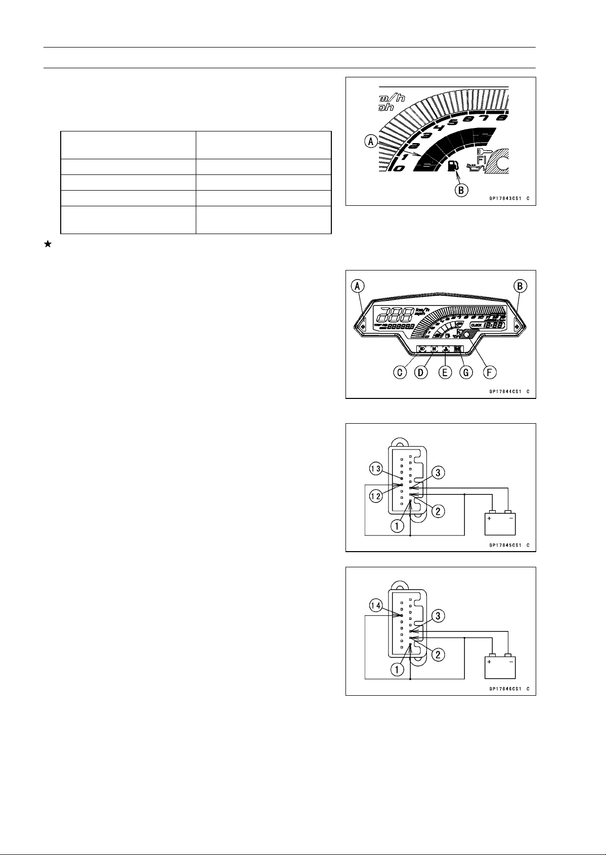
16-76 ELECTRICAL SYSTEM
Meter, Gauge, Indicator Unit
•
Check that the number of segments [A] matches the re-
sistance value of the variable rheostat.
○
When the terminal [16] is connected, one segment in the
fuel level gauge should appear about every 15 seconds.
Variable Rheostat
Resistance ()
Display Segments
10 6
90 3
180 1
200
1 (Flash)
Fuel Symbol [B] (Flash)
If the display function does not work, replace the meter
assembly.
Indicator Lights Inspection
•
Connect the 12 V battery and terminals in the same man-
ner as specified in the “Liquid Crystal Display (LCD) Seg-
ments Check”.
Left Turn Signal Indicator Light (LED) [A]
Right Turn Signal Indicator Light (LED) [B]
High Beam Indicator Light (LED) [C]
Neutral Indicator Light (LED) [D]
Water Temperature Warning Indicator Light (LED) [E]
Warning Indicator Light (LED) [F]
ABS Indicator Light (LED) [G] (Equipped Models)
•
Using the auxiliary leads, connect a 12 V battery to the
meter unit connector as follows.
Left and Right Turn Signal Indicator Light (LED)
Battery Positive (+) Terminal to Terminal [12] (Left)
Battery Positive (+) Terminal to Terminal [13] (Right)
High Beam Indicator Light (LED)
Battery Positive (+) Terminal to Terminal [14]
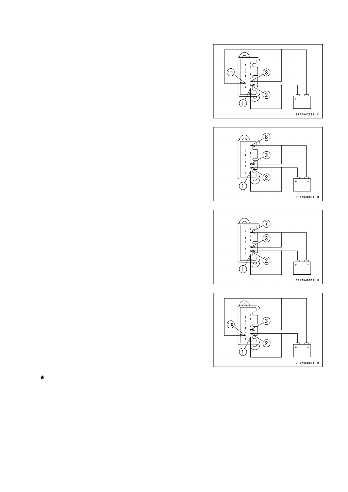
ELECTRICAL SYSTEM 16-77
Meter, Gauge, Indicator Unit
Neutral Indicator Light (LED)
Battery Negative (–) Terminal to Terminal [11]
Water Temperature Warning Indicator Light (LED)
Battery Negative (–) Terminal to Terminal [8]
○
The water temperature indicator light (LED) goes on
about 2 seconds after when the terminal [8] was con-
nected.
Warning Indicator Light (LED) (Oil Pressure Warning)
Battery Negative (–) Terminal to Terminal [7]
○
When the terminal [7] was connected, the warning in-
dicator light blinks and the oil pressure warning symbol
flashes.
ABS Indicator Light (LED) (Equipped Models)
Battery Negative (–) Terminal to Terminal [10]
If each light (LED) does not go on, replace the meter as-
sembly.
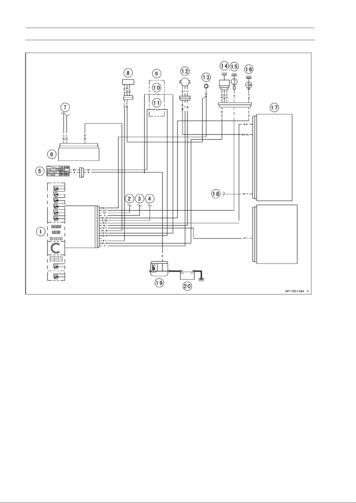
16-78 ELECTRICAL SYSTEM
Meter, Gauge, Indicator Unit
Meter Circuit
1. Meter Unit
2. to Turn Signal Switch (Right)
3. to Turn Signal Switch (Left)
4. to Dimmer Switch and Passing Button
(Equipped Models)
5. Ignition Switch
6. ABS Hydrauric Unit (Equipped Models)
7. to France Ground
8. Fuel Level Gauge
9. Fuse Box
10. Meter Fuse 10 A
11. Ignition Fuse 15 A
12. Speed Sensor
13. Meter Ground
14. Water Temperature Sensor
15. Neutral Switch
16. Oil Pressure Switch
17. ECU
18. to Meter Ground
19. Main Fuse 30 A
20. Battery 12 V 8 Ah
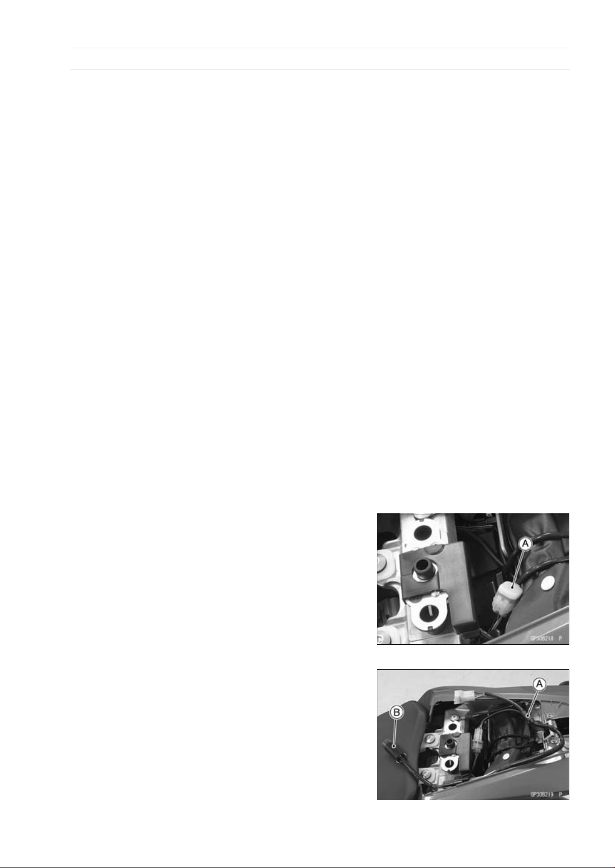
ELECTRICAL SYSTEM 16-79
Immobilizer System (Equipped Models), ZR1000DA/EA
This motorcycle is equipped with an immobilizer system to protect the motorcycle from theft. This
system provides a theft proof device by means of matching a code between the inbuilt key transponder
and ECU (Electronic Control Unit). If the code does not match, ignition system, injectors, subthrottle
valve actuator and exhaust butterfly valve actuator will not operate and the engine will not start.
Abstract
•
Do not keep more than one immobilizer key of any system on a key ring. Jamming of the key code
signal may occur and the operation of the system may be affected.
•
The warning indicator light (LED) will flash for a period of 24 hours once the ignition switch has been
switched off and the key removed. This flashing can be set to on or off as desired by holding the
left and right buttons down for two seconds within twenty seconds of switching the ignition off.
•
If all coded keys (master key and user keys) are lost the ECU and ignition switch will have to be
replaced.
•
The immobilizer system can not function until the master key code is registered in the ECU.
•
A total of six keys can be registered in the ECU at any one time (one master key and five user keys).
•
If the master key is lost it is not possible to register new user keys.
Operational Cautions
1. Do not put two keys of any immobilizer system on the same key ring.
2. Do not submerge any key in water.
3. Do not expose any key to excessively high temperature.
4. Do not place any key close to magnet.
5. Do not place a heavy item on any key.
6. Do not grind any key or alter its shape.
7. Do not disassemble the plastic part of any key.
8. Do not drop the key and/or apply any shocks to the key.
9. When a user key is lost, the user should go to his dealer to invalidate the lost key registration in
the ECU.
10.When the master key is lost, the user should go to his dealer and have a new ECU installed and
register a new master key and user keys.
NOTE
○
No.9 and 10 are strongly recommended to the customer to ensure security of the motorcycle.
Key Registration
Case 1: When the user key has been lost or additional
spare user key is required.
•
Prepare a new spare user key.
•
Cut the key in accordance with the shape of the current
user key.
•
Remove:
Rear Seat (see Rear Seat Removal in the Frame chap-
ter)
•
Remove the immobilizer/Kawasaki diagnostic system
connector cap [A].
•
Connect the key registration adapter [A] and key registra-
tion unit [B].
Special Tools - Key Registration Unit: 57001-1582
Key Registration Adapter: 57001-1746
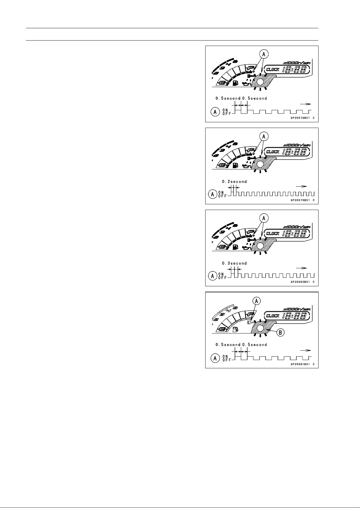
16-80 ELECTRICAL SYSTEM
Immobilizer System (Equipped Models), ZR1000DA/EA
•
Insert the master key into the ignition switch, and turn it
to ON.
Verified
○
The warning indicator light (LED) and the immobilizer
warning symbol [A] blink to display the registration mode
(go to the next step).
Not Verified
○
The warning indicator light (LED) and the immobilizer
warning symbol [A] blink to display the collation error
(refer to the following failure illustrations).
Immobilizer Amplifier Failure
Master Key Collation Error
•
Turn off the ignition switch and remove the master key.
○
The immobilizer warning symbol [A] disappears.
○
The warning indicator light (LED) [B] then blinks for 15
seconds; it means the ECU is in the registration mode.
○
After 15 seconds, the ECU ends the registration mode
and stops blinking the warning indicator light (LED).
NOTE
○
Insert and turn on the next key between 15 seconds that
the ECU is in the registration mode.
○
When a registration mode was ended, do the master
key verification procedure over again to restart it. This
applies to all user key registration.
•
Insert the user key 1 into the ignition switch, and turn it to
ON.
NOTE
○
Keep other user keys away from the immobilizer an-
tenna.
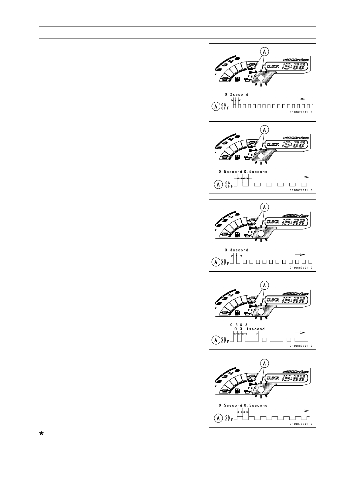
ELECTRICAL SYSTEM 16-81
Immobilizer System (Equipped Models), ZR1000DA/EA
○
If there is any problem in the registration, the warning
indicator light (LED) and the immobilizer warning symbol
[A] blink to display the collation error.
Immobilizer Amplifier Failure
When Registered User Key is Inserted.
User Key Collation Error
•
The user key 1 is successfully registered in the ECU.
○
The warning indicator light (LED) and the immobilizer
warning symbol [A] blink 2 times and stop for 1 second
and then repeat this cycle.
•
Turn off the ignition switch and remove the user key 1.
○
The immobilizer warning symbol [A] disappears.
○
The warning indicator light (LED) then blinks for 15 sec-
onds.
○
After 15 seconds, the ECU ends the registration mode
and stops blinking the warning indicator light (LED).
NOTE
○
This procedure registered the master key and one user
key.
If more keys registration is needed, go to next procedures
within the registration mode.
•
Insert the user key 2 into the ignition switch, and turn it to
ON.
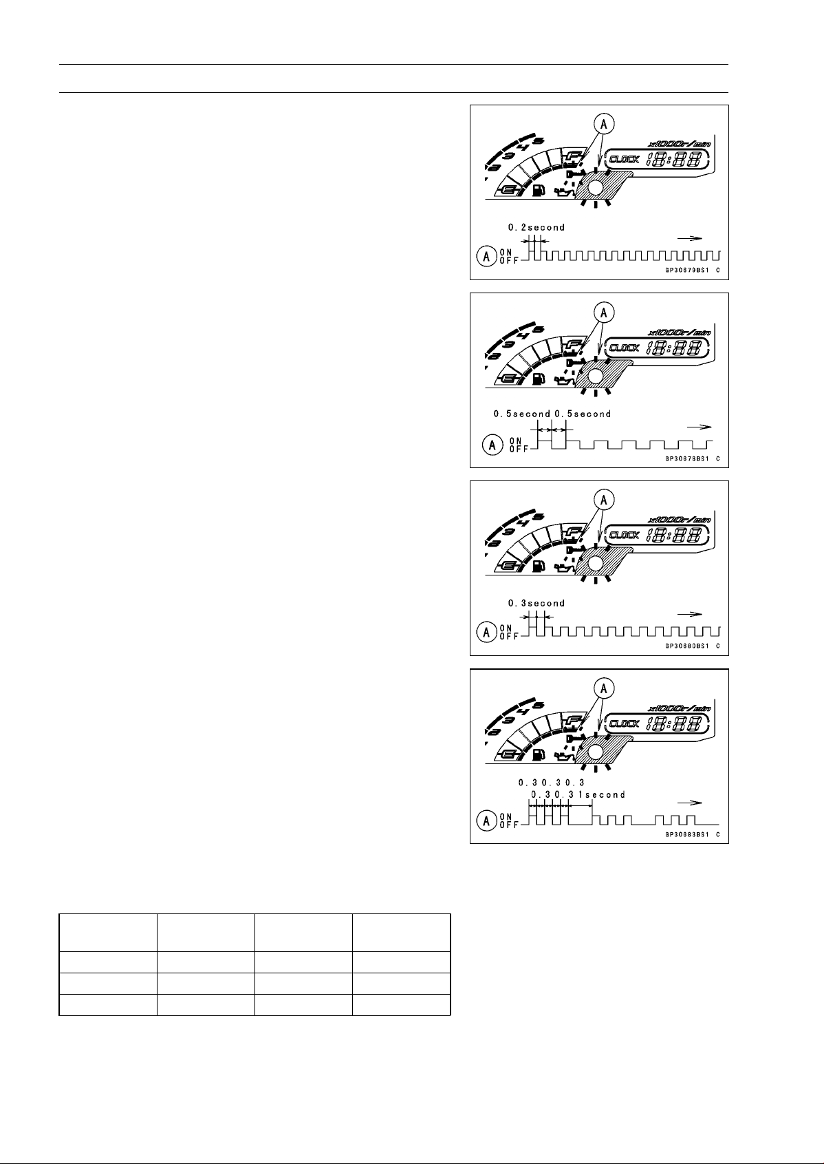
16-82 ELECTRICAL SYSTEM
Immobilizer System (Equipped Models), ZR1000DA/EA
○
If there is any problem in the registration, the warning
indicator light (LED) and the immobilizer warning symbol
[A] blink to display the collation error.
Immobilizer Amplifier Failure
When Registered User Key is Inserted.
User Key Collation Error
•
The user key 2 is successfully registered in the ECU.
○
The warning indicator light (LED) and the immobilizer
warning symbol [A] blink 3 times and stop for 1 second
and then repeat this cycle.
○
This procedure has registered the master key and 2 user
keys.
•
Continue with the procedure if neccesary to register an
additional 3 user keys.
NOTE
○
The ECU can store up the six key codes (master key ×
1 and user key × 5).
User Key Indicator Flashes
Indicator
Light Blinks
Indicator
Light Stops
Remarks
User Key 3 4times 1 second Repeat
User Key 4 5times 1 second Repeat
User Key 5 6times 1 second Repeat
•
Turn to OFF the ignition switch and wait for period of more
than 15 seconds.
•
The registration mode automatically ends.
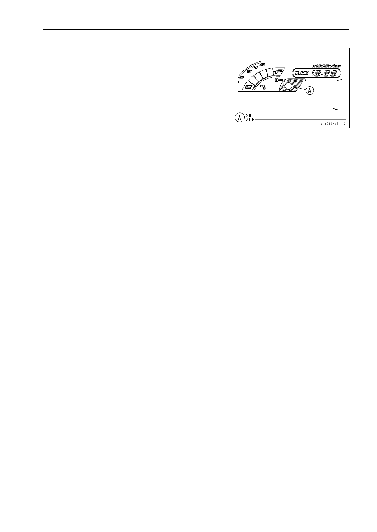
ELECTRICAL SYSTEM 16-83
Immobilizer System (Equipped Models), ZR1000DA/EA
•
The warning indicator light (LED) [A] goes off.
•
Remove the key registration unit, key registration adapter
and install the immobilizer/Kawasaki diagnostic system
connector cap.
NOTE
○
Turn the ignition switch to ON with the registered user
key.
○
Check that the engine can be started using all regis-
tered user keys.
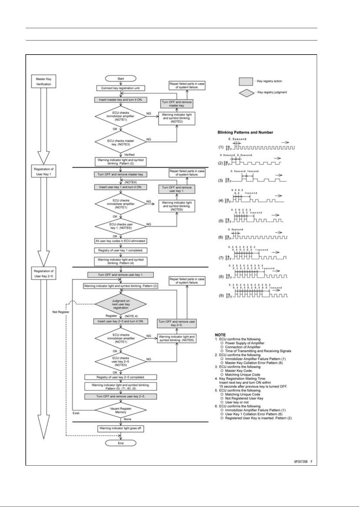
16-84 ELECTRICAL SYSTEM
Immobilizer System (Equipped Models), ZR1000DA/EA
Spare User Key Registration Flow Chart
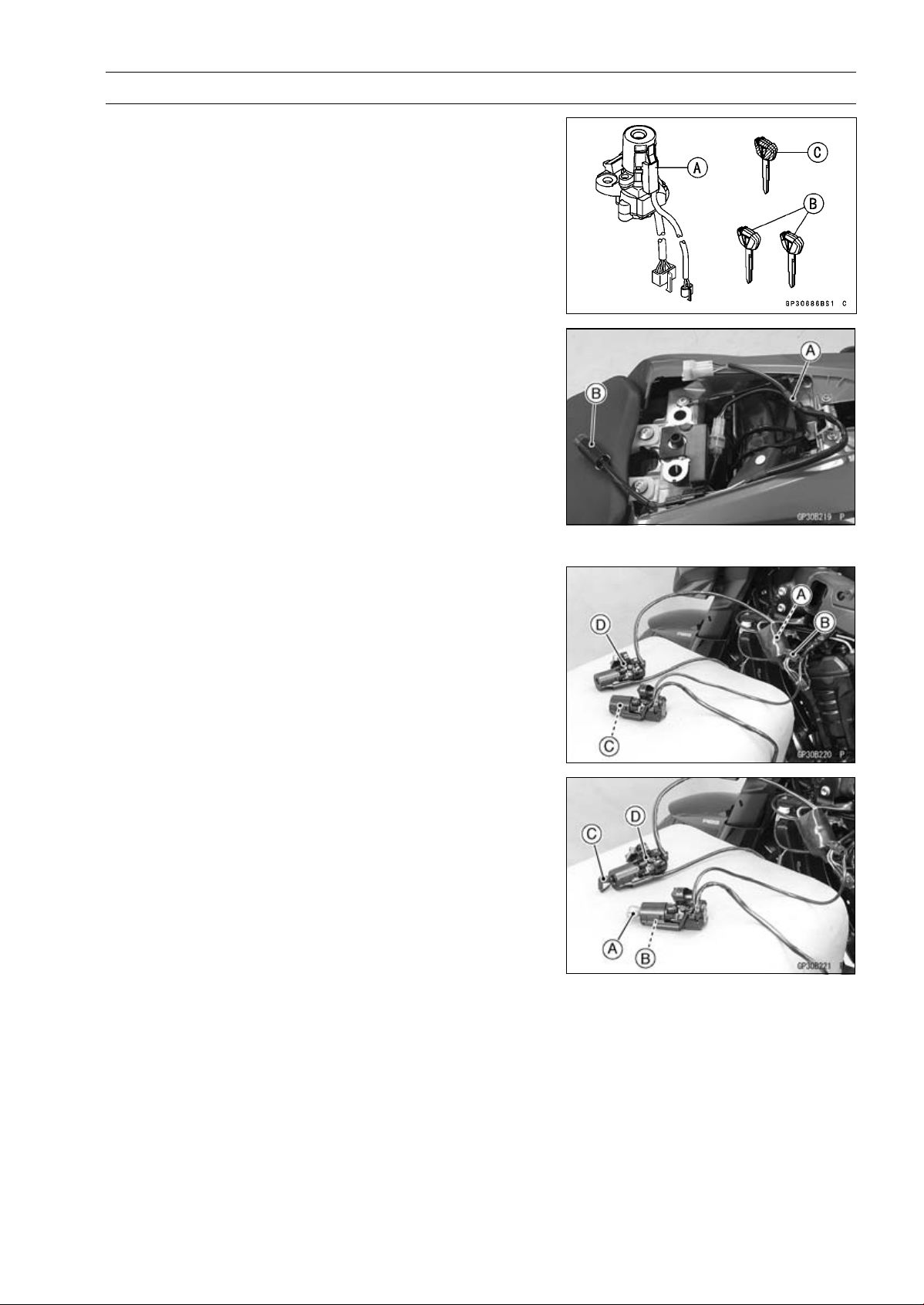
ELECTRICAL SYSTEM 16-85
Immobilizer System (Equipped Models), ZR1000DA/EA
Case 2: When the ignition switch is faulty and to be
replaced.
•
Prepare a new ignition switch [A] and two new user keys
[B].
○
These parts are available as a set. Prepare the current
master key [C].
•
Remove:
Ignition Switch and Immobilizer Antenna (see Immobi-
lizer System Parts Replacement)
Rear Seat (see Rear Seat Removal in the Frame chap-
ter)
•
Remove the immobilizer/Kawasaki diagnostic system
connector cap.
•
Connect the key registration adapter [A] and key registra-
tion unit [B].
Special Tools - Key Registration Unit: 57001-1582
Key Registration Adapter: 57001-1746
•
Connect:
New Ignition Switch Lead Connector [A]
Immobilizer Antenna Lead Connector [B]
NOTE
○
Keep the antenna [C] more than 15 cm (5.9 in.) from
the ignition switch [D].
•
Put the current master key [A] at the antenna [B].
•
Insert the new user key 1 [C] into the new ignition switch
[D], and turn it to ON.
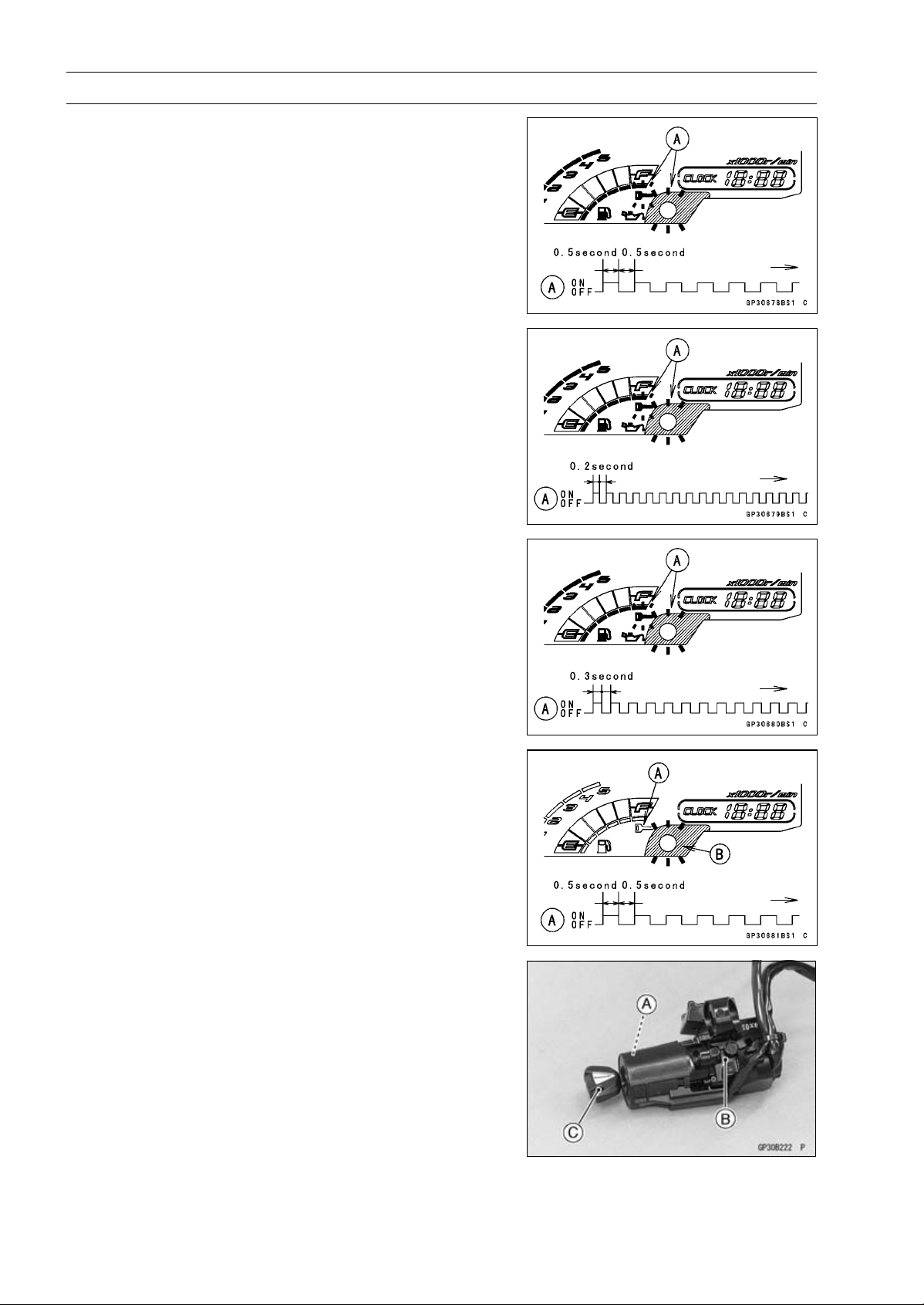
16-86 ELECTRICAL SYSTEM
Immobilizer System (Equipped Models), ZR1000DA/EA
Verified
○
The warning indicator light (LED) and the immobilizer
warning symbol [A] blink to display the ECU is in the
registration mode (go to the next step).
Not Verified
○
The warning indicator light (LED) and the immobilizer
warning symbol [A] blink to display the collation error.
Immobilizer Amplifier Failure
Master Key Collation Error
•
Turn off the ignition switch and remove the user key 1.
○
The immobilizer warning symbol [A] disappears.
○
The warning indicator light (LED) [B] then blinks for 15
seconds; it means the ECU is in the registration mode.
○
After 15 seconds, the ECU ends the registration mode
and stops blinking the warning indicator light (LED).
•
Temporarily place the antenna [A] on the new ignition
switch [B].
•
Insert the user key 1 [C] again into the new ignition switch,
and turn it to ON.
NOTE
○
Place the antenna on the ignition switch, insert and turn
on the user key between 15 seconds that the ECU is in
the registration mode.
○
When a registration mode was ended, do the master
key verification procedure over again to restart it. This
applies to all user key registration.
○
Keep other user keys away from the immobilizer an-
tenna.
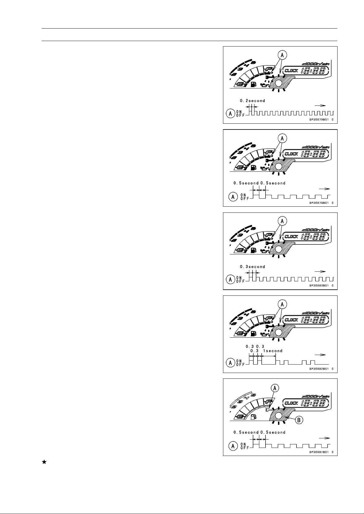
ELECTRICAL SYSTEM 16-87
Immobilizer System (Equipped Models), ZR1000DA/EA
○
If there is any problem in the registration, the warning
indicator light (LED) and the immobilizer warning symbol
[A] blink to display the collation error.
Immobilizer Amplifier Failure
When Registered User Key is Inserted.
User Key Collation Error
•
The user key 1 is successfully registered in the ECU.
○
The warning indicator light (LED) and the immobilizer
warning symbol [A] blink 2 times and stop for 1 second
and then repeat this cycle.
•
Turn off the ignition switch and remove the user key 1.
○
The immobilizer warning symbol [A] disappears.
○
The warning indicator light (LED) [B] then blinks for 15
seconds.
○
After 15 seconds, the ECU ends the registration mode
and stops blinking the warning indicator light (LED).
NOTE
○
This procedure registered the master key and one user
key.
If more keys registration is needed, go to next procedures
within the registration mode.
•
Insert the user key 2 into the ignition switch, and turn it to
ON.
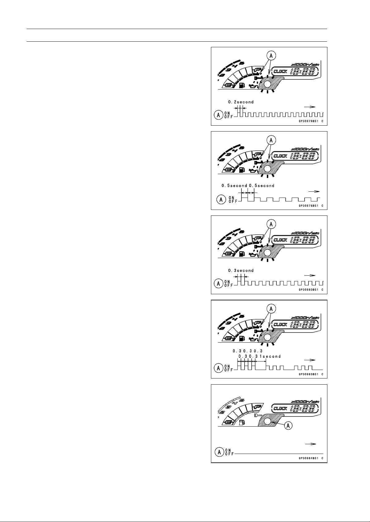
16-88 ELECTRICAL SYSTEM
Immobilizer System (Equipped Models), ZR1000DA/EA
○
If there is any problem in the registration, the warning
indicator light (LED) and the immobilizer warning symbol
[A] blink to display the collation error.
Immobilizer Amplifier Failure
When Registered User Key is Inserted.
User Key Collation Error
•
The user key 2 is successfully registered in the ECU.
○
The warning indicator light (LED) and the immobilizer
warning symbol [A] blink 3 times and stop for 1 second
and then repeat this cycle.
○
This procedure has registered the master key and 2 user
keys.
•
Turn to OFF the ignition switch and wait for period of more
than 15 seconds.
•
The registration mode automatically ends.
•
The warning indicator light (LED) [A] goes off.
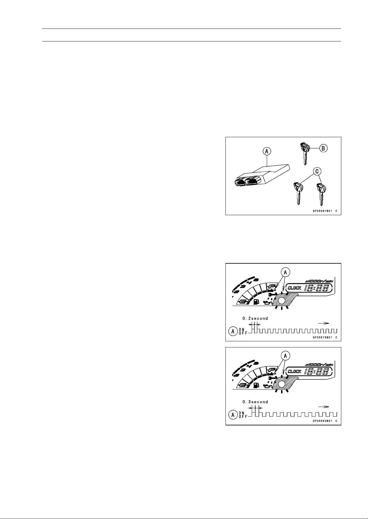
ELECTRICAL SYSTEM 16-89
Immobilizer System (Equipped Models), ZR1000DA/EA
•
Remove the key registration unit, key registration adapter
and install the immobilizer/Kawasaki diagnostic system
connector cap.
NOTE
○
Turn the ignition switch to ON with the registered user
key.
○
Check that the engine can be started using all regis-
tered user keys.
•
Install the new ignition switch and antenna (see Immobi-
lizer System Parts Replacement).
Case 3: When the ECU is faulty and has to be replaced.
•
Prepare a new ECU [A], current master key [B] and cur-
rent user keys [C].
NOTE
○
The key registration unit is not required.
○
After replacing the ECU, be sure to register the master
key and 2 user keys. If the 3 keys (master key × 1 and
user key × 2) are not registered, the engine can not be
started.
•
Replace:
ECU (see Immobilizer System Parts Replacement)
•
Insert the current master key into the ignition switch and
turn it to ON.
○
If there is any problem in the registration, the warning
indicator light (LED) and the immobilizer warning symbol
[A] blink to display the collation error.
Immobilizer Amplifier Failure
Master Key Collation Error
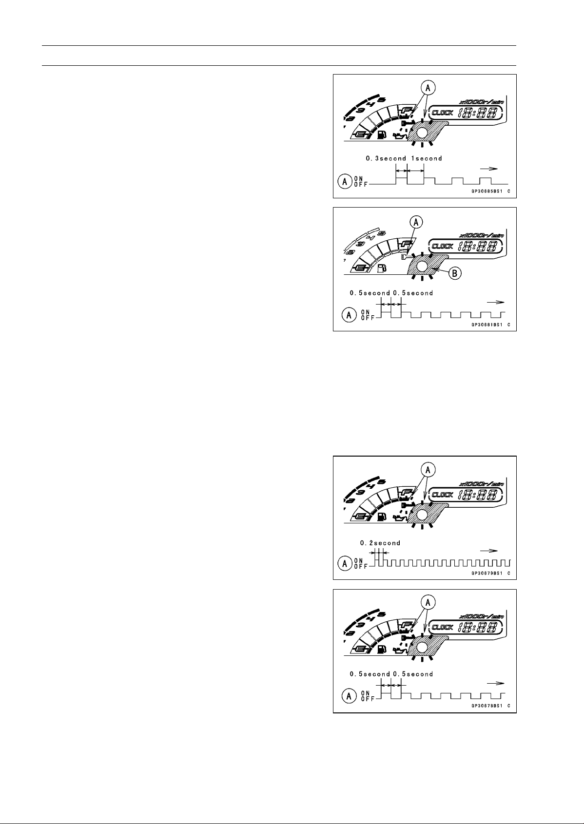
16-90 ELECTRICAL SYSTEM
Immobilizer System (Equipped Models), ZR1000DA/EA
•
The master key is successfully registered in the ECU.
○
The warning indicator light (LED) and the immobilizer
warning symbol [A] blink 1 time and stop for 1 second
and then repeat this cycle.
•
Turn off the ignition switch and remove the master key.
○
The immobilizer warning symbol [A] disappears.
○
The warning indicator light (LED) [B] then blinks for 15
seconds; it means the ECU is in the registration mode.
○
After 15 seconds, the ECU ends the registration mode
and stops blinking the warning indicator light (LED).
NOTE
○
Insert and turn on the next key between 15 seconds that
the ECU is in the registration mode.
○
When a registration mode was ended, do the master
key verification procedure over again to restart it. This
applies to all user key registration.
•
Insert the user key 1 into the ignition switch, and turn it to
ON.
NOTE
○
Keep other user keys away from the immobilizer an-
tenna.
○
If there is any problem in the registration, the warning
indicator light (LED) and the immobilizer warning symbol
[A] blink to display the collation error.
Immobilizer Amplifier Failure
When Registered User Key is Inserted.
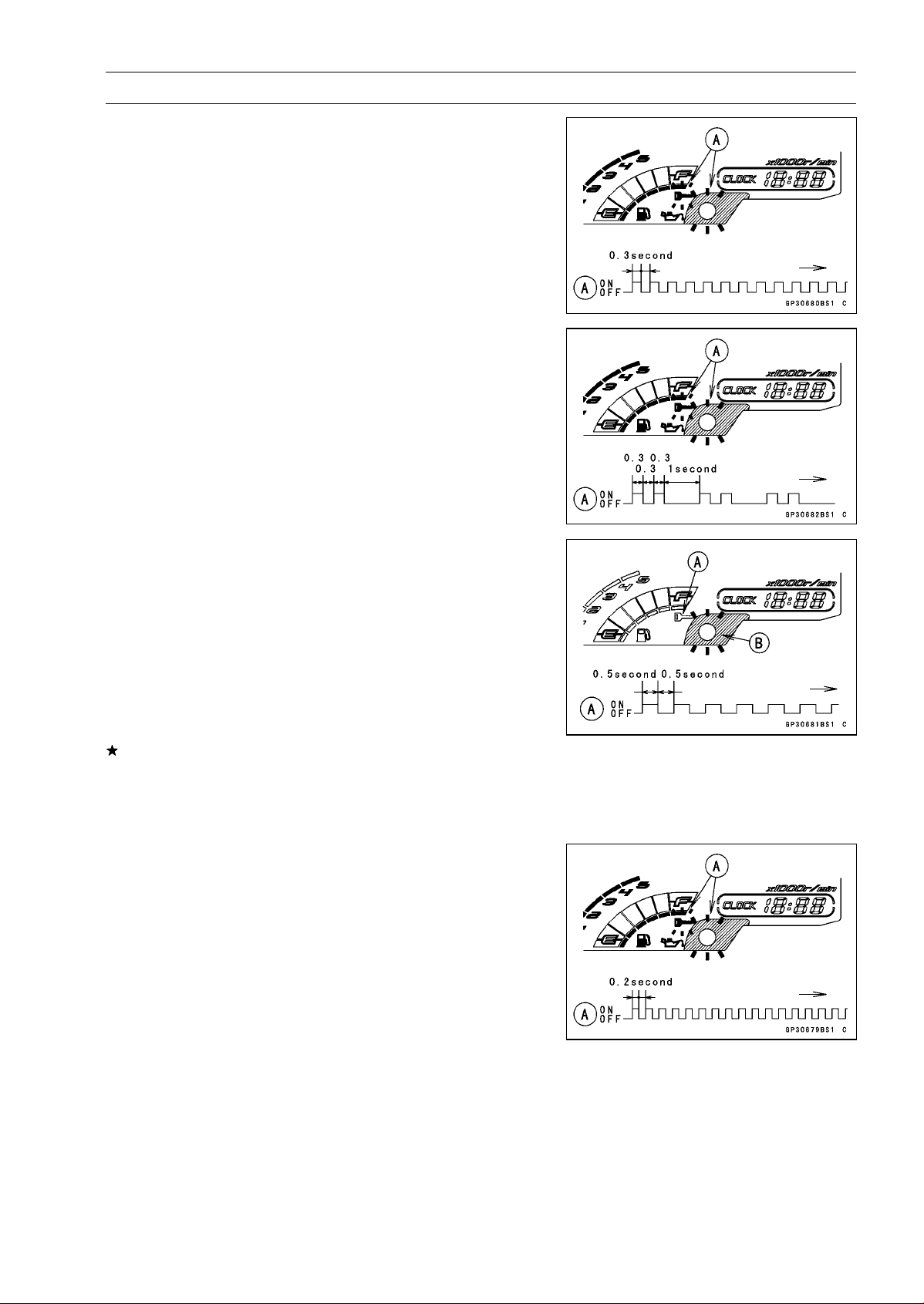
ELECTRICAL SYSTEM 16-91
Immobilizer System (Equipped Models), ZR1000DA/EA
User Key Collation Error
•
The user key 1 is registered in the ECU.
○
The warning indicator light (LED) and the immobilizer
warning symbol [A] blink 2 times and stop for 1 second
and then repeat this cycle.
•
Turn off the ignition switch and remove the user key 1.
○
The immobilizer warning symbol [A] disappears.
○
The warning indicator light (LED) [B] then blinks for 15
seconds.
○
After 15 seconds, the ECU ends the registration mode
and stops blinking the warning indicator light (LED).
NOTE
○
This procedure registered the master key and one user
key.
If more keys registration is needed, go to next procedures
within the registration mode.
•
Insert the user key 2 into the ignition switch, and turn it to
ON.
○
If there is any problem in the registration, the warning
indicator light (LED) and the immobilizer warning symbol
[A] blink to display the collation error code.
Immobilizer Amplifier Failure
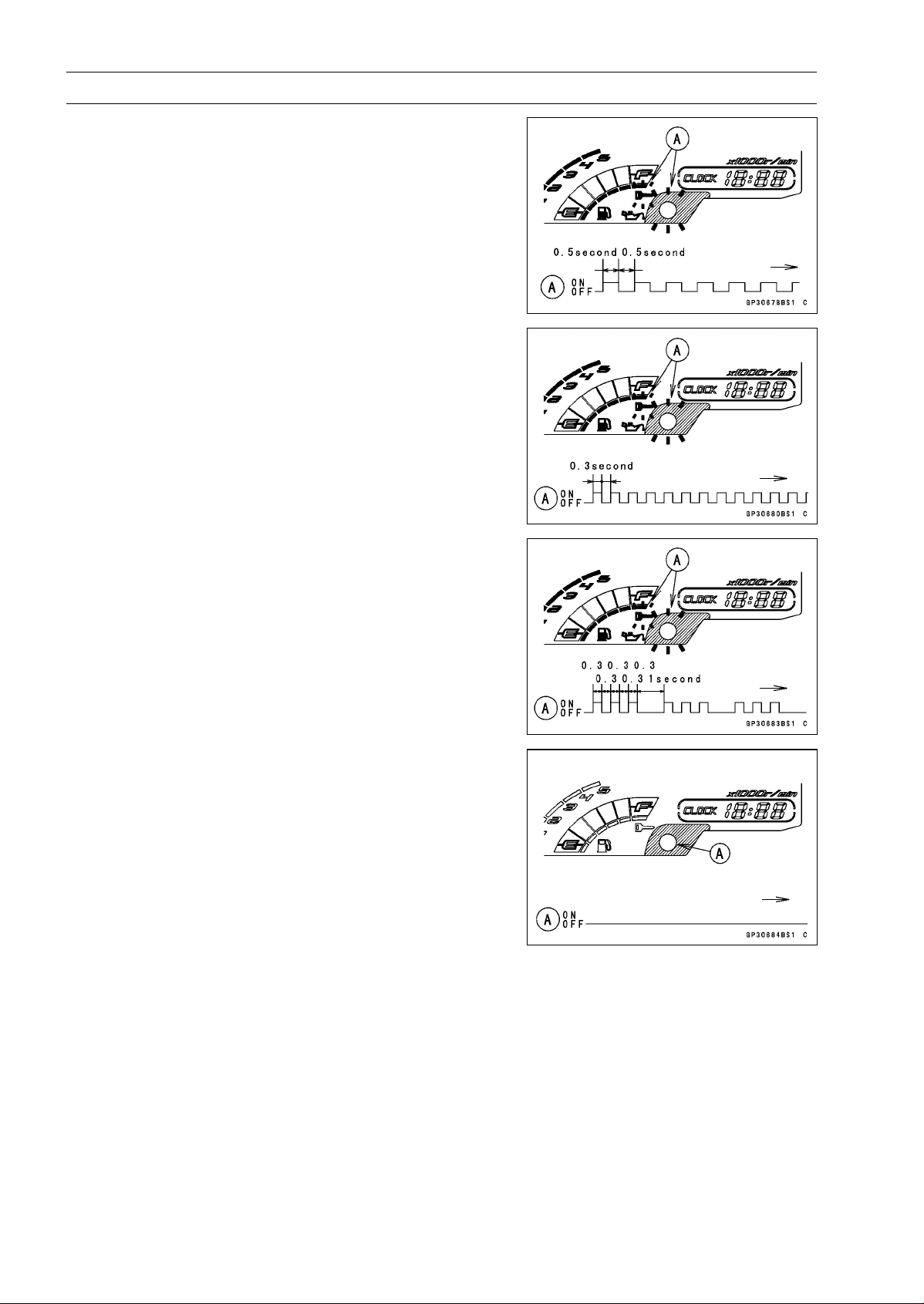
16-92 ELECTRICAL SYSTEM
Immobilizer System (Equipped Models), ZR1000DA/EA
When Registered User Key is Inserted.
User Key Collation Error
•
The user key 2 is successfully registered in the ECU.
○
The warning indicator light (LED) and the immobilizer
warning symbol [A] blink 3 times and stop for 1 second
and then repeat this cycle.
○
This procedure has registered the master key and 2 user
keys.
•
Turn to OFF the ignition switch and wait for period of more
than 15 seconds.
•
The registration mode automatically ends.
•
The warning indicator light (LED) [A] goes off.
NOTE
○
Turn the ignition switch to ON with the registered user
key.
○
Check that the engine can be started using all regis-
tered user keys.
Case 4: When master key is faulty or lost.
The master key replacement is considered very rare case.
However if it is required, the following is necessary.
NOTE
○
The ECU must be replaced with a new one because the
master key code that is registered in the current ECU
can not be rewritten.
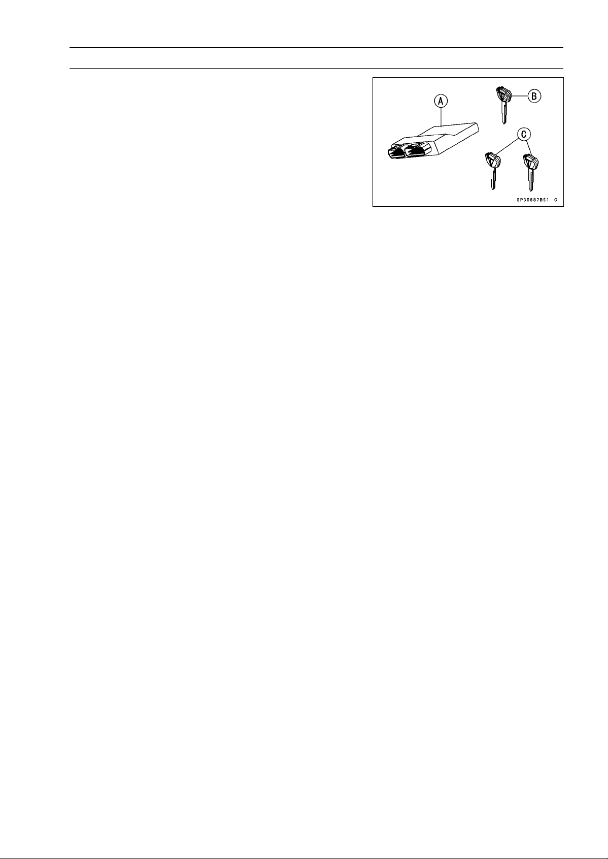
ELECTRICAL SYSTEM 16-93
Immobilizer System (Equipped Models), ZR1000DA/EA
•
Prepare a new ECU [A], new master key [B] and current
user keys [C].
NOTE
○
The key registration unit is not required.
○
The key registration process is same as the case 3.
Case 5: When replacing the antenna.
•
Prepare a new antenna.
•
Refer to the Immobilizer System Parts Replacement.
NOTE
○
No key registration is required.
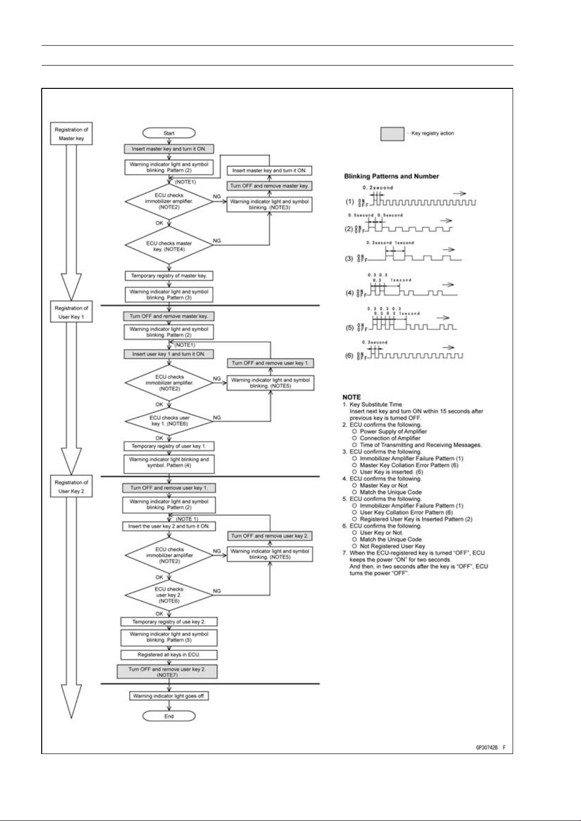
16-94 ELECTRICAL SYSTEM
Immobilizer System (Equipped Models), ZR1000DA/EA
All Keys Initial Registration Flow Chart
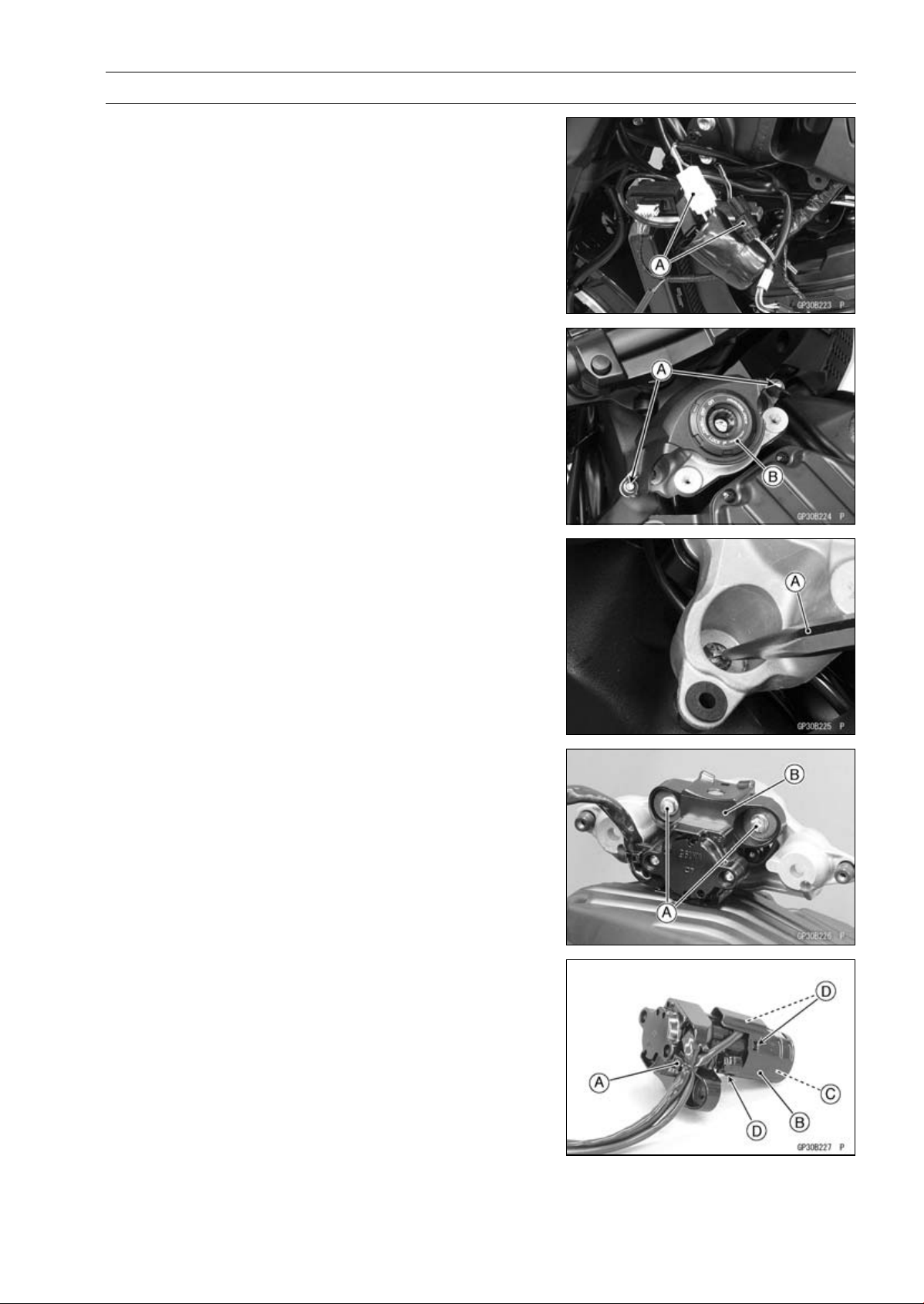
ELECTRICAL SYSTEM 16-95
Immobilizer System (Equipped Models), ZR1000DA/EA
Immobilizer System Parts Replacement
Immobilizer Antenna Replacement
•
Remove:
Fuel Tank (see Fuel Tank Removal in the Fuel System
(DFI) chapter)
Left Center Fairing (see Center Fairing Removal in the
Frame chapter)
•
Disconnect the lead connectors [A].
•
Remove:
Bolts [A]
Ignition Switch Cover [B]
•
Using a small chisel [A] or punch, turn out the Torx bolts.
•
Remove:
Bolts [A]
Ignition Switch [B]
•
Cut the band [A].
•
Remove the antenna cover [B] to take out the antenna
[C].
○
Clear the projections [D] of the ignition switch to remove
the cover.
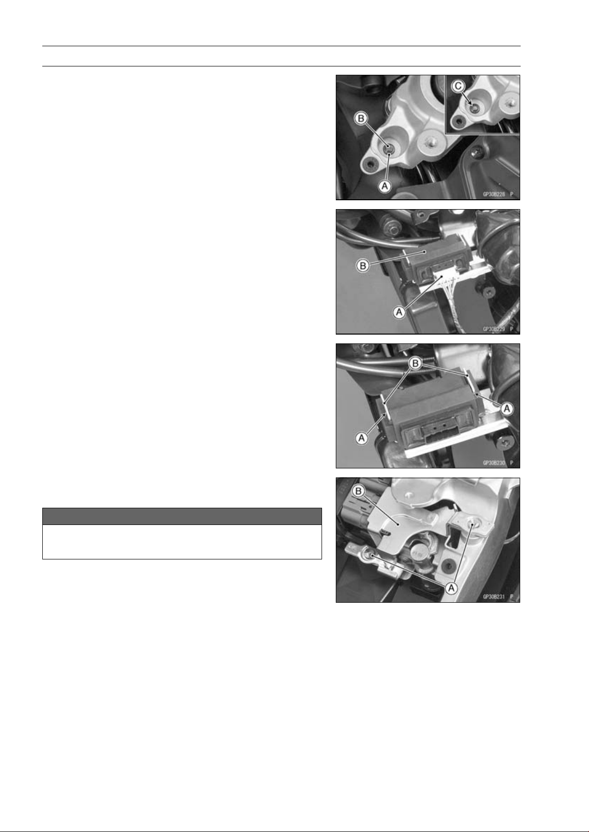
16-96 ELECTRICAL SYSTEM
Immobilizer System (Equipped Models), ZR1000DA/EA
•
Tighten a new Torx bolt [A] until the bolt head [B] is broken
[C].
•
Run the leads correctly (see Cable, Wire, and Hose Rout-
ing section in the Appendix chapter).
Immobilizer Amplifier Replacement
•
Remove:
Left Center Fairing (see Center Fairing Removal in the
Frame chapter)
Immobilizer Amplifier connector [A]
Immobilizer Amplifier [B]
•
Fit the slits [A] on the damper to the bracket projections
[B].
ECU (Electronic Control Unit) Replacement (for Immo-
bilizer Models)
NOTICE
Never drop the ECU, especially on a hard surface.
Such a shock to the ECU can damage it.
•
Remove:
Seat Cover (see Seat Cover Removal in the Frame
chapter)
•
Using a small chisel or other suitable tool, remove the
screws [A] and ECU guard [B].
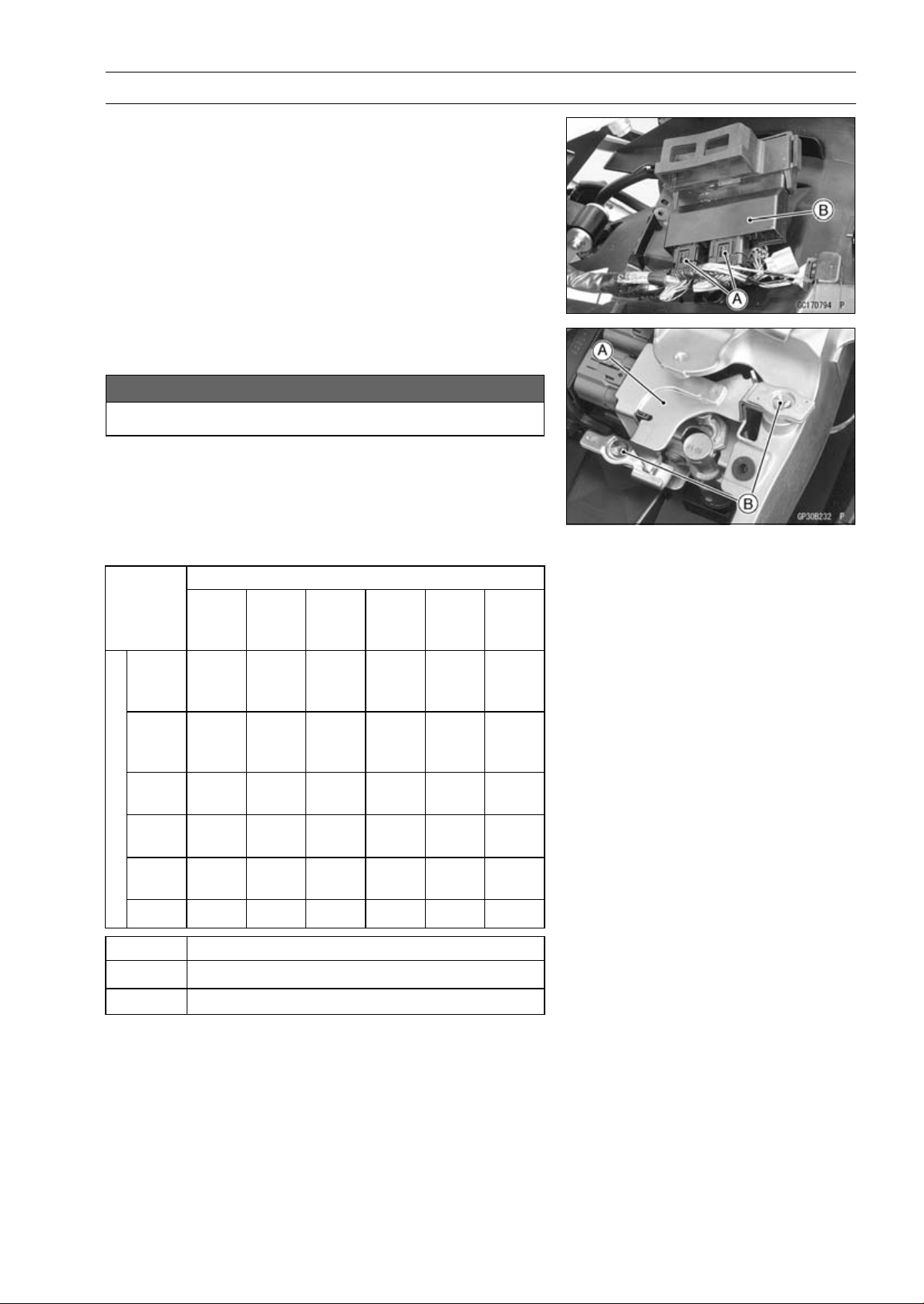
ELECTRICAL SYSTEM 16-97
Immobilizer System (Equipped Models), ZR1000DA/EA
•
Remove:
Relay Box (see Relay Box Removal)
ECU Connectors [A]
ECU [B]
•
Connect the connectors to the ECU.
•
Install the ECU guard [A].
NOTICE
Do not pinch the leads.
•
Tighten the new screws [B] using the Kawasaki genuine
screws of which threads are coated with locking agent.
Immobilizer Relational Parts Replacement Chart
Failed or Lost Part
Master
Key
(Red)
User
Key
(Black)
Ignition
Switch
An-
tenna
Ampli-
fier
ECU
Master
Key
(Red)
•
User
Key
(Black)
•
○
Ignition
Switch
•
An-
tenna
•
Ampli-
fier
•
*
ECU
○
•
*
Replacement Part
•
Main Replacement Part
○
Additional Replacement Part
Immobilizer System Inspection
•
Refer to the Immobilizer Amplifier and Blank Key Detec-
tion section in the Fuel System (DFI) chapter.
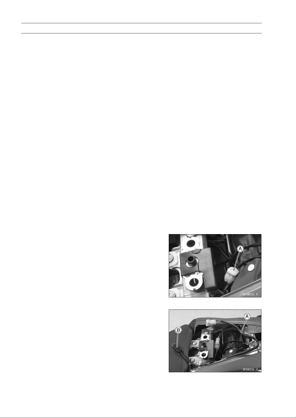
16-98 ELECTRICAL SYSTEM
Immobilizer System (Equipped Models), ZR1000DB ∼/EB ∼
This motorcycle is equipped with an immobilizer system to protect the motorcycle from theft. This
system provides a theft proof device by means of matching a code between the inbuilt key transponder
and ECU (Electronic Control Unit). If the code does not match, ignition system, injectors, subthrottle
valve actuator and exhaust butterfly valve actuator will not operate and the engine will not start.
Abstract
•
Do not keep more than one immobilizer key of any system on a key ring. Jamming of the key code
signal may occur and the operation of the system may be affected.
•
The warning indicator light (LED) will flash for a period of 24 hours once the ignition switch has been
switched off and the key removed. This flashing can be set to on or off as desired by holding the
left and right buttons down for two seconds within twenty seconds of switching the ignition off.
•
If all coded keys are lost the ECU and ignition switch will have to be replaced.
•
The immobilizer system can not function until the ignition key code is registered in the ECU.
•
A total of five keys can be registered in the ECU at any one time.
Operational Cautions
1. Do not put two keys of any immobilizer system on the same key ring.
2. Do not submerge any key in water.
3. Do not expose any key to excessively high temperature.
4. Do not place any key close to magnet.
5. Do not place a heavy item on any key.
6. Do not grind any key or alter its shape.
7. Do not disassemble the plastic part of any key.
8. Do not drop the key and/or apply any shocks to the key.
9. When a ignition key is lost, the user should go to his dealer to invalidate the lost key registration
in the ECU.
10.When the all ignition key is lost, the user should go to his dealer and have a new ECU installed
and register the ignition keys.
NOTE
○
No.9 and 10 are strongly recommended to the customer to ensure security of the motorcycle.
Key Registration
Case 1: When the ignition key has been lost or addi-
tional spare ignition key is required.
•
Prepare a new spare ignition key.
•
Cut the key in accordance with the shape of the current
ignition key.
•
Remove:
Rear Seat (see Rear Seat Removal in the Frame chap-
ter)
•
Remove the immobilizer/Kawasaki diagnostic system
connector cap [A].
•
Connect the key registration adapter [A] and key registra-
tion unit [B].
Special Tools - Key Registration Unit: 57001-1582
Key Registration Adapter: 57001-1746
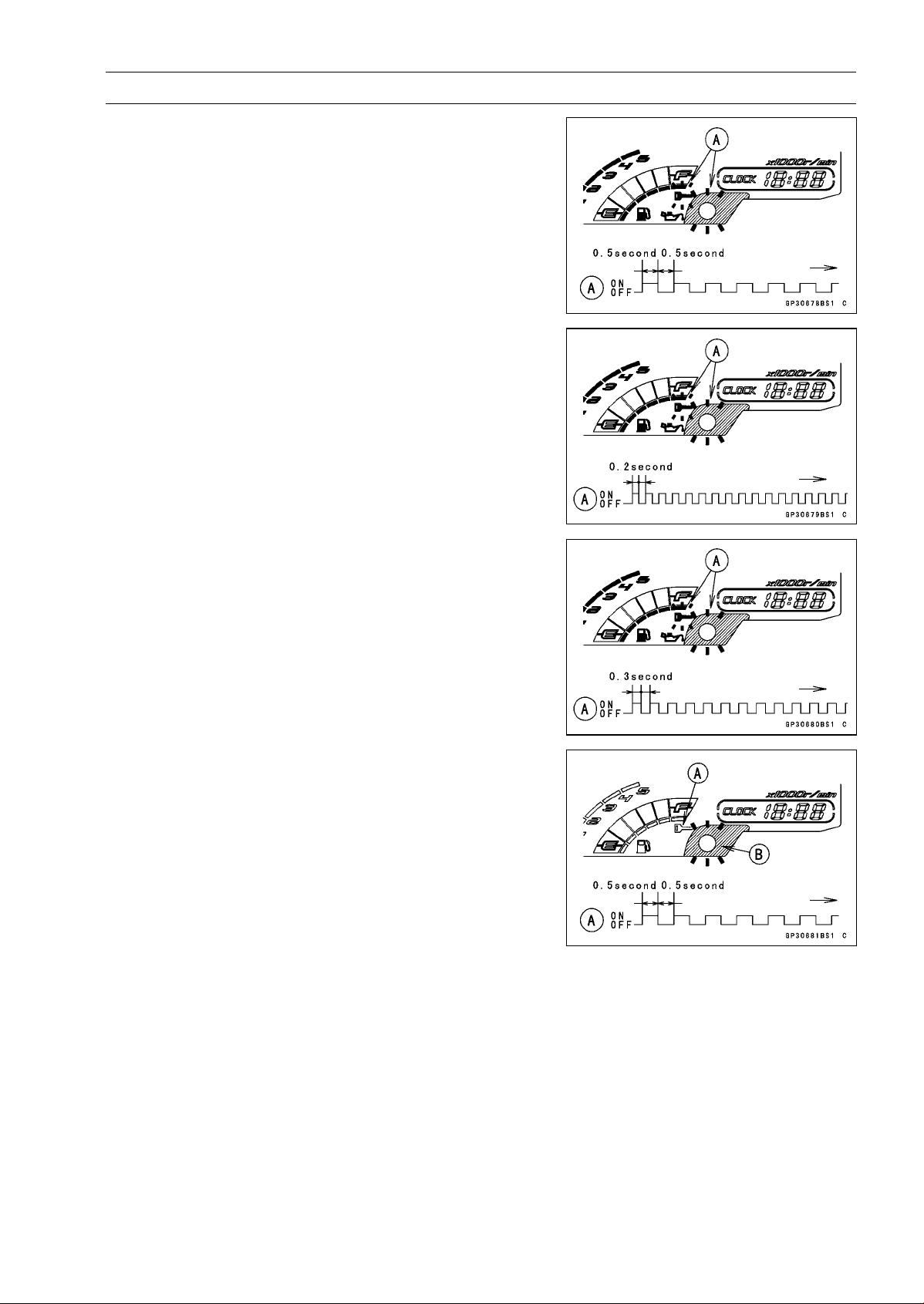
ELECTRICAL SYSTEM 16-99
Immobilizer System (Equipped Models), ZR1000DB ∼/EB ∼
•
Insert the registered ignition key into the ignition switch,
and turn it to ON.
Verified
○
The warning indicator light (LED) and the immobilizer
warning symbol [A] blink to display the registration mode
(go to the next step).
Not Verified
○
The warning indicator light (LED) and the immobilizer
warning symbol [A] blink to display the collation error
(refer to the following failure illustrations).
Immobilizer Amplifier Failure
Registered Ignition Key Collation Error
•
Turn off the ignition switch and remove the registered ig-
nition key.
○
The immobilizer warning symbol [A] disappears.
○
The warning indicator light (LED) [B] then blinks for 15
seconds; it means the ECU is in the registration mode.
○
After 15 seconds, the ECU ends the registration mode
and stops blinking the warning indicator light (LED).
NOTE
○
Insert and turn on the next key between 15 seconds that
the ECU is in the registration mode.
○
When a registration mode was ended, do the regis-
tered ignition key(s) verification procedure over again
to restart it. This applies to all ignition key registration.
•
Insert the ignition key 1 into the ignition switch, and turn
it to ON.
NOTE
○
Keep other ignition keys away from the immobilizer an-
tenna.
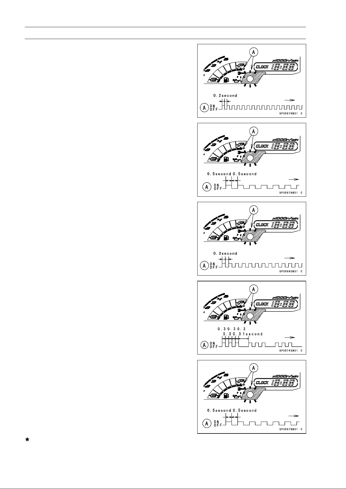
16-100 ELECTRICAL SYSTEM
Immobilizer System (Equipped Models), ZR1000DB ∼/EB ∼
○
If there is any problem in the registration, the warning
indicator light (LED) and the immobilizer warning symbol
[A] blink to display the collation error.
Immobilizer Amplifier Failure
When Registered Ignition Key is Inserted.
Ignition Key Collation Error
•
The ignition key 1 is successfully registered in the ECU.
○
The warning indicator light (LED) and the immobilizer
warning symbol [A] blink 3 times and stop for 1 second
and then repeat this cycle.
•
Turn off the ignition switch and remove the ignition key 1.
○
The immobilizer warning symbol [A] disappears.
○
The warning indicator light (LED) then blinks for 15 sec-
onds.
○
After 15 seconds, the ECU ends the registration mode
and stops blinking the warning indicator light (LED).
NOTE
○
This procedure registered the registered ignition key
and one ignition key.
If more keys registration is needed, go to next procedures
within the registration mode.
•
Insert the ignition key 2 into the ignition switch, and turn
it to ON.
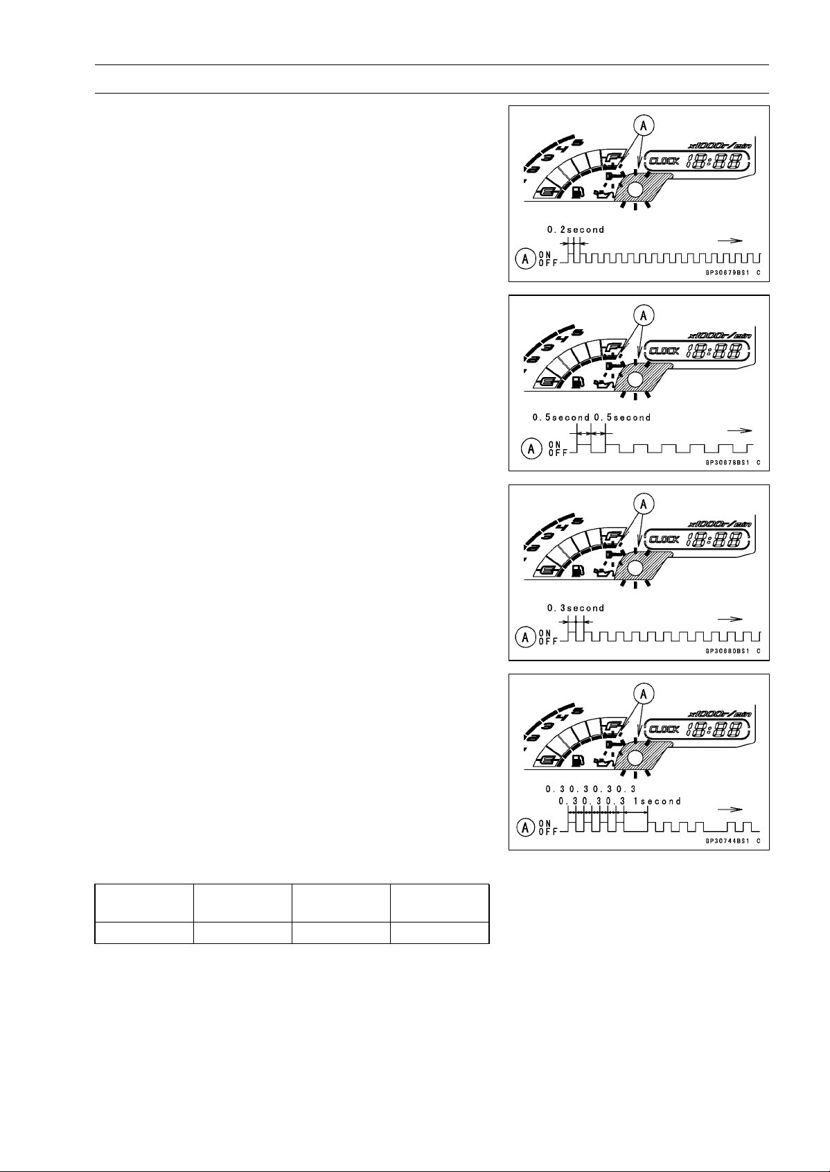
ELECTRICAL SYSTEM 16-101
Immobilizer System (Equipped Models), ZR1000DB ∼/EB ∼
○
If there is any problem in the registration, the warning
indicator light (LED) and the immobilizer warning symbol
[A] blink to display the collation error.
Immobilizer Amplifier Failure
When Registered Ignition Key is Inserted.
Ignition Key Collation Error
•
The ignition key 2 is successfully registered in the ECU.
○
The warning indicator light (LED) and the immobilizer
warning symbol [A] blink 4 times and stop for 1 second
and then repeat this cycle.
○
This procedure has registered the 2 ignition keys.
•
Continue with the procedure if necessary to register an
additional one ignition key.
NOTE
○
The ECU can store up the five key codes.
Ignition Key Indicator Flashes
Indicator
Light Blinks
Indicator
Light Stops
Remarks
Ignition Key 3 5times 1 second Repeat
•
Turn to OFF the ignition switch and wait for period of more
than 15 seconds.
•
The registration mode automatically ends.
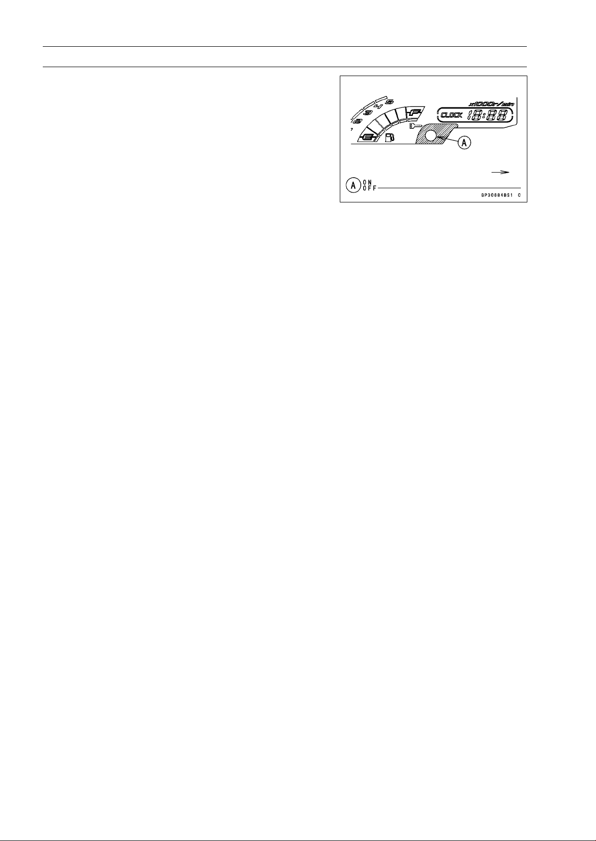
16-102 ELECTRICAL SYSTEM
Immobilizer System (Equipped Models), ZR1000DB ∼/EB ∼
•
The warning indicator light (LED) [A] goes off.
•
Remove the key registration unit, key registration adapter
and install the immobilizer/Kawasaki diagnostic system
connector cap.
NOTE
○
Turn the ignition switch to ON with the registered ignition
key.
○
Check that the engine can be started using all regis-
tered ignition keys.
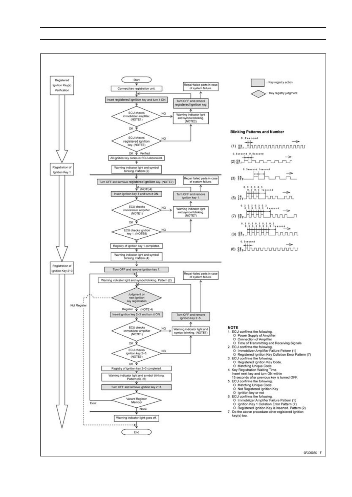
ELECTRICAL SYSTEM 16-103
Immobilizer System (Equipped Models), ZR1000DB ∼/EB ∼
Spare Ignition Key Registration Flow Chart
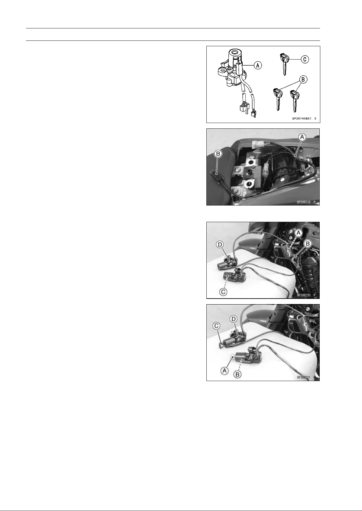
16-104 ELECTRICAL SYSTEM
Immobilizer System (Equipped Models), ZR1000DB ∼/EB ∼
Case 2: When the ignition switch is faulty and to be
replaced.
•
Prepare a new ignition switch [A] and two new ignition
keys [B].
○
These parts are available as a set. Prepare the current
registered ignition key [C].
•
Remove:
Ignition Switch and Immobilizer Antenna (see Immobi-
lizer System Parts Replacement)
Rear Seat (see Rear Seat Removal in the Frame chap-
ter)
•
Remove the immobilizer/Kawasaki diagnostic system
connector cap.
•
Connect the key registration adapter [A] and key registra-
tion unit [B].
Special Tools - Key Registration Unit: 57001-1582
Key Registration Adapter: 57001-1746
•
Connect:
New Ignition Switch Lead Connector [A]
Immobilizer Antenna Lead Connector [B]
NOTE
○
Keep the antenna [C] more than 15 cm (5.9 in.) from
the ignition switch [D].
•
Put the current registered user key [A] at the antenna [B].
•
Insert the new ignition key 1 [C] into the new ignition
switch [D], and turn it to ON.
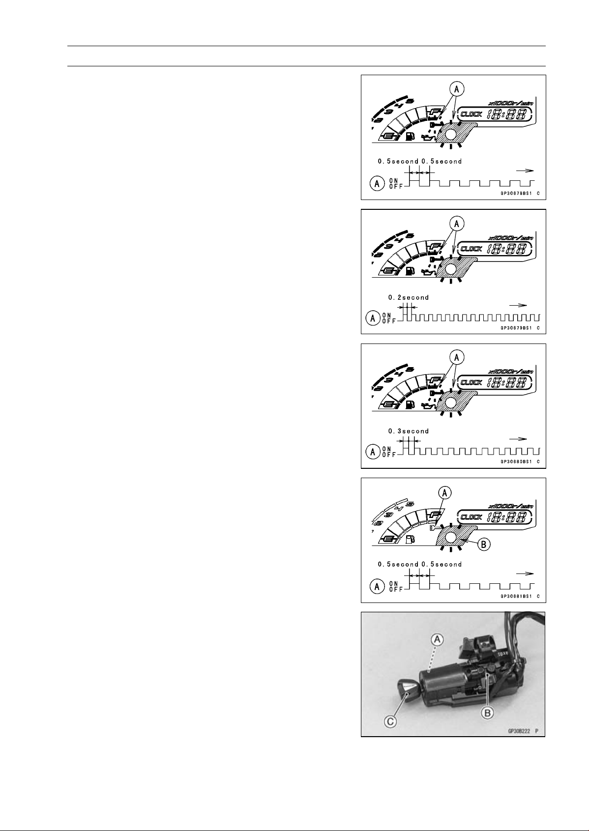
ELECTRICAL SYSTEM 16-105
Immobilizer System (Equipped Models), ZR1000DB ∼/EB ∼
Verified
○
The warning indicator light (LED) and the immobilizer
warning symbol [A] blink to display the ECU is in the
registration mode (go to the next step).
Not Verified
○
The warning indicator light (LED) and the immobilizer
warning symbol [A] blink to display the collation error.
Immobilizer Amplifier Failure
Registered Ignition Key Collation Error
•
Turn off the ignition switch and remove the ignition key 1.
○
The immobilizer warning symbol [A] disappears.
○
The warning indicator light (LED) [B] then blinks for 15
seconds; it means the ECU is in the registration mode.
○
After 15 seconds, the ECU ends the registration mode
and stops blinking the warning indicator light (LED).
•
Temporarily place the antenna [A] on the new ignition
switch [B].
•
Insert the ignition key 1 [C] again into the new ignition
switch, and turn it to ON.
NOTE
○
Place the antenna on the ignition switch, insert and turn
on the ignition key between 15 seconds that the ECU is
in the registration mode.
○
When a registration mode was ended, do the registered
ignition key verification procedure over again to restart
it. This applies to all ignition key registration.
○
Keep other ignition keys away from the immobilizer an-
tenna.
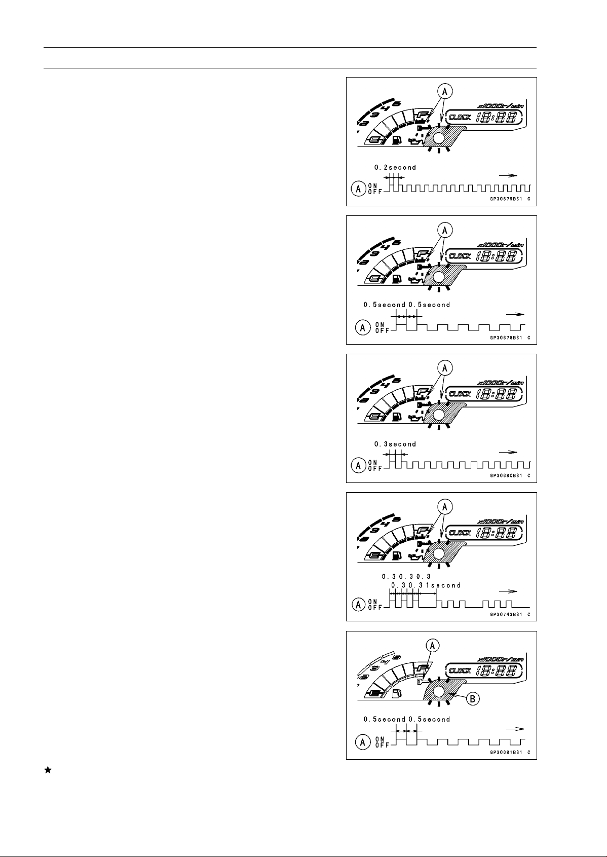
16-106 ELECTRICAL SYSTEM
Immobilizer System (Equipped Models), ZR1000DB ∼/EB ∼
○
If there is any problem in the registration, the warning
indicator light (LED) and the immobilizer warning symbol
[A] blink to display the collation error.
Immobilizer Amplifier Failure
When Registered Ignition Key is Inserted.
Ignition Key Collation Error
•
The ignition key 1 is successfully registered in the ECU.
○
The warning indicator light (LED) and the immobilizer
warning symbol [A] blink 3 times and stop for 1 second
and then repeat this cycle.
•
Turn off the ignition switch and remove the ignition key 1.
○
The immobilizer warning symbol [A] disappears.
○
The warning indicator light (LED) [B] then blinks for 15
seconds.
○
After 15 seconds, the ECU ends the registration mode
and stops blinking the warning indicator light (LED).
NOTE
○
This procedure registered the registered ignition key
and one ignition key.
If more keys registration is needed, go to next procedures
within the registration mode.
•
Insert the ignition key 2 into the ignition switch, and turn
it to ON.
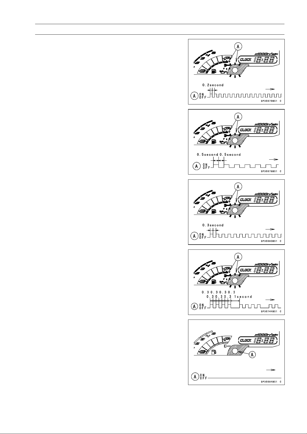
ELECTRICAL SYSTEM 16-107
Immobilizer System (Equipped Models), ZR1000DB ∼/EB ∼
○
If there is any problem in the registration, the warning
indicator light (LED) and the immobilizer warning symbol
[A] blink to display the collation error.
Immobilizer Amplifier Failure
When Registered Ignition Key is Inserted.
Ignition Key Collation Error
•
The ignition key 2 is successfully registered in the ECU.
○
The warning indicator light (LED) and the immobilizer
warning symbol [A] blink 4 times and stop for 1 second
and then repeat this cycle.
○
This procedure has registered the registered ignition key
and 2 ignition keys.
•
Turn to OFF the ignition switch and wait for period of more
than 15 seconds.
•
The registration mode automatically ends.
•
The warning indicator light (LED) [A] goes off.
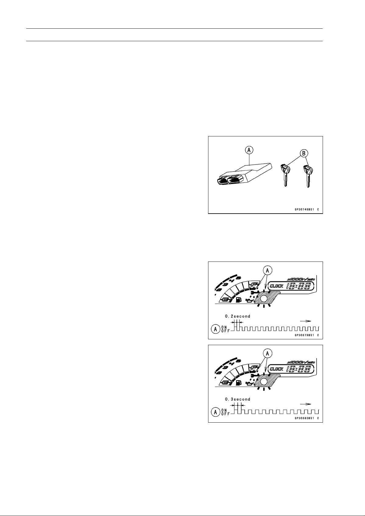
16-108 ELECTRICAL SYSTEM
Immobilizer System (Equipped Models), ZR1000DB ∼/EB ∼
•
Remove the key registration unit, key registration adapter
and install the immobilizer/Kawasaki diagnostic system
connector cap.
NOTE
○
Turn the ignition switch to ON with the registered ignition
key.
○
Check that the engine can be started using all regis-
tered ignition keys.
•
Install the new ignition switch and antenna (see Immobi-
lizer System Parts Replacement).
Case 3: When the ECU is faulty and has to be replaced.
•
Prepare a new ECU [A] and current ignition key(s) [B].
NOTE
○
The key registration unit is not required.
○
After replacing the ECU, be sure to register the 2 ignition
keys. If the 2 keys are not registered, the engine can
not be started.
•
Replace:
ECU (see Immobilizer System Parts Replacement)
•
Insert the current registered ignition key into the ignition
switchandturnittoON.
○
If there is any problem in the registration, the warning
indicator light (LED) and the immobilizer warning symbol
[A] blink to display the collation error.
Immobilizer Amplifier Failure
Registered Ignition Key Collation Error
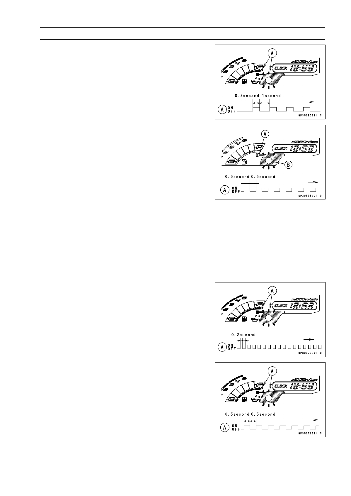
ELECTRICAL SYSTEM 16-109
Immobilizer System (Equipped Models), ZR1000DB ∼/EB ∼
•
The registered ignition key is successfully registered in
the ECU.
○
The warning indicator light (LED) and the immobilizer
warning symbol [A] blink 1 time and stop for 1 second
and then repeat this cycle.
•
Turn off the ignition switch and remove the registered ig-
nition key.
○
The immobilizer warning symbol [A] disappears.
○
The warning indicator light (LED) [B] then blinks for 15
seconds; it means the ECU is in the registration mode.
○
After 15 seconds, the ECU ends the registration mode
and stops blinking the warning indicator light (LED).
NOTE
○
Insert and turn on the next key between 15 seconds that
the ECU is in the registration mode.
○
When a registration mode was ended, do the registered
ignition key verification procedure over again to restart
it. This applies to all ignition key registration.
•
Insert the other remaining registered ignition key into the
ignition switch, and turn it to ON.
NOTE
○
Keep other ignition keys away from the immobilizer an-
tenna.
○
If there is any problem in the registration, the warning
indicator light (LED) and the immobilizer warning symbol
[A] blink to display the collation error.
Immobilizer Amplifier Failure
When Registered Ignition Key is Inserted.
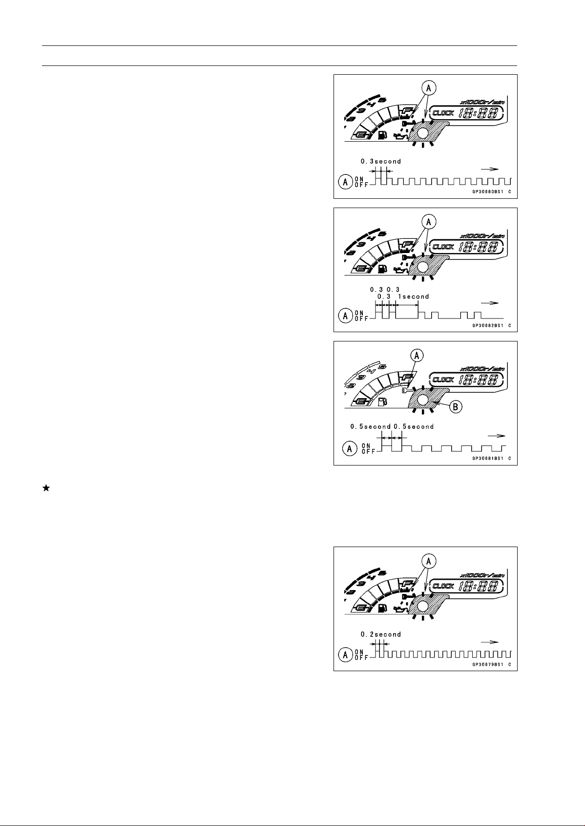
16-110 ELECTRICAL SYSTEM
Immobilizer System (Equipped Models), ZR1000DB ∼/EB ∼
Ignition Key Collation Error
•
The other remaining ignition key is registered in the ECU.
○
The warning indicator light (LED) and the immobilizer
warning symbol [A] blink 2 times and stop for 1 second
and then repeat this cycle.
•
Turn off the ignition switch and remove the other remain-
ing ignition key.
○
The immobilizer warning symbol [A] disappears.
○
The warning indicator light (LED) [B] then blinks for 15
seconds.
○
After 15 seconds, the ECU ends the registration mode
and stops blinking the warning indicator light (LED).
NOTE
○
This procedure registered the registered ignition key
and one ignition key.
If more keys registration is needed, go to next procedures
within the registration mode.
•
Insert the ignition key 1 into the ignition switch, and turn
it to ON.
○
If there is any problem in the registration, the warning
indicator light (LED) and the immobilizer warning symbol
[A] blink to display the collation error code.
Immobilizer Amplifier Failure
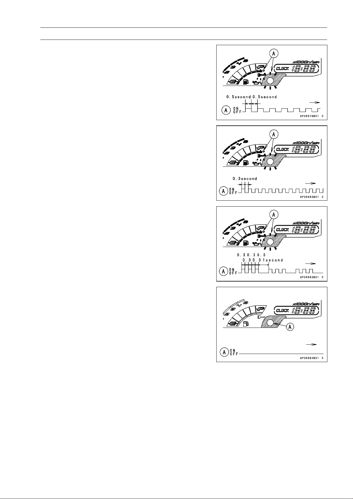
ELECTRICAL SYSTEM 16-111
Immobilizer System (Equipped Models), ZR1000DB ∼/EB ∼
When Registered Ignition Key is Inserted.
Ignition Key Collation Error
•
The ignition key 1 is successfully registered in the ECU.
○
The warning indicator light (LED) and the immobilizer
warning symbol [A] blink 3 times and stop for 1 second
and then repeat this cycle.
○
This procedure has registered the registered ignition key
and 2 ignition keys.
•
Turn to OFF the ignition switch and wait for period of more
than 15 seconds.
•
The registration mode automatically ends.
•
The warning indicator light (LED) [A] goes off.
NOTE
○
Turn the ignition switch to ON with the registered ignition
key.
○
Check that the engine can be started using all regis-
tered ignition keys.
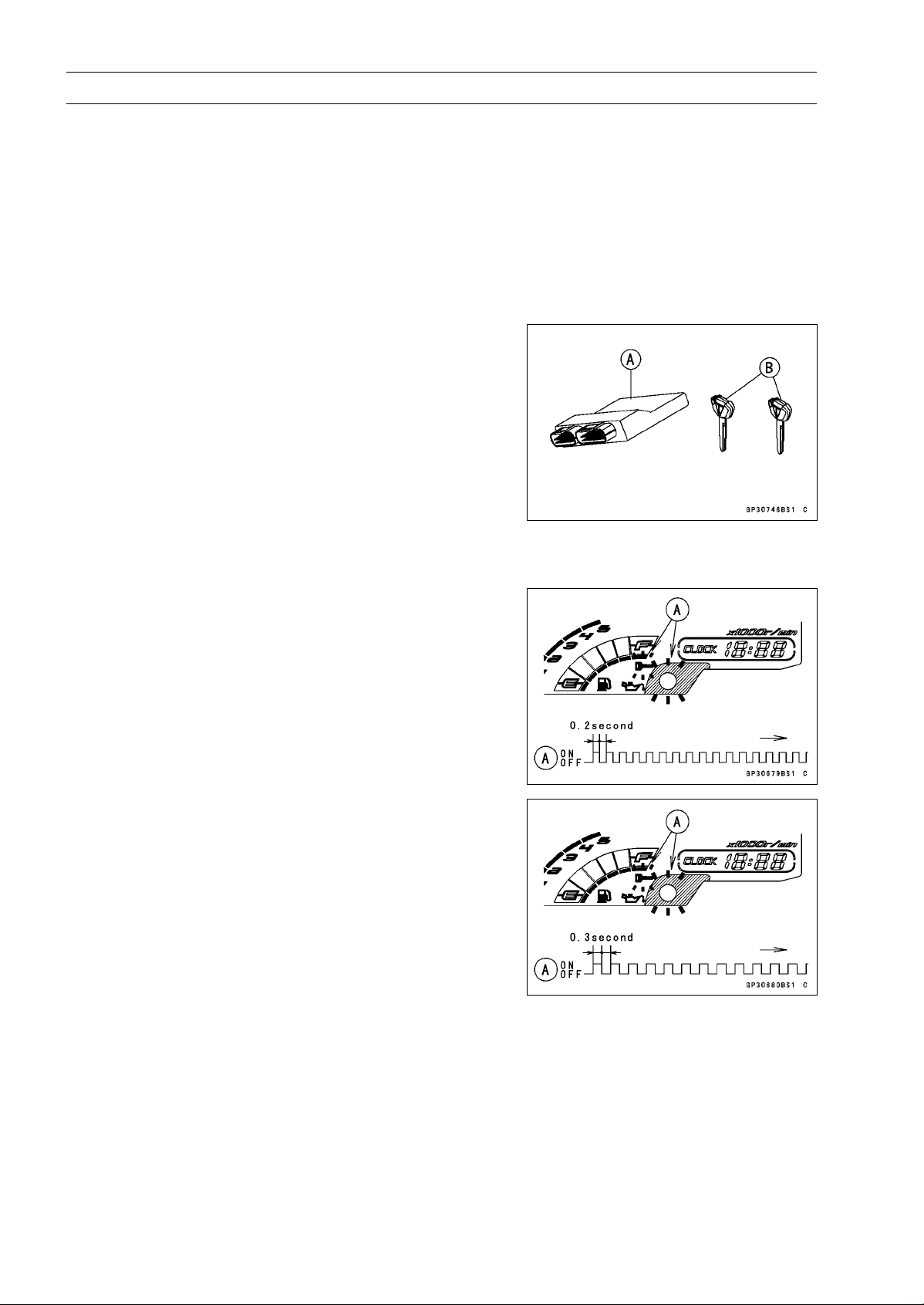
16-112 ELECTRICAL SYSTEM
Immobilizer System (Equipped Models), ZR1000DB ∼/EB ∼
Case 4: When all registered ignition keys are faulty or
lost.
The all registered ignition keys replacement is considered
very rare case. However if it is required, the following is
necessary.
NOTE
○
The ECU must be replaced with a new one because
the registered ignition key code that is registered in the
current ECU can not be rewritten.
•
Prepare a new ECU [A] and 2 new ignition keys [B].
NOTE
○
The key registration unit is not required.
○
The key registration process is same as the case 3.
•
Insert the first ignition key into the ignition switch and turn
it ON.
○
If there is any problem in the registration, the warning
indicator light (LED) and the immobilizer warning symbol
[A] blink to display the collation error.
Immobilizer Amplifier Failure
Ignition Key Collation Error
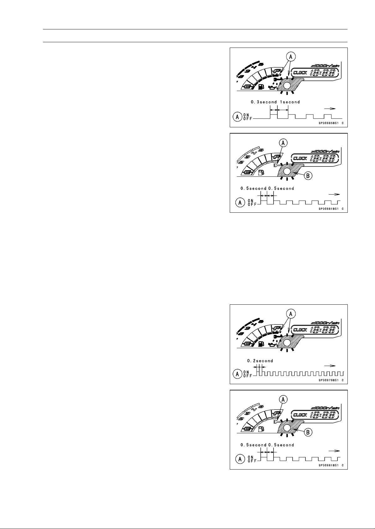
ELECTRICAL SYSTEM 16-113
Immobilizer System (Equipped Models), ZR1000DB ∼/EB ∼
•
The first ignition key is successfully registered in the ECU.
○
The warning indicator light (LED) and the immobilizer
warning symbol [A] blink 1 time and stops for 1 second
and the repeats this cycle to indicate successful registra-
tion of the first ignition key.
•
Turn off the ignition switch and remove the first ignition
key.
○
The immobilizer warning symbol [A] disappears.
○
The warning indicator light (LED) [B] then blinks for 15
seconds; it means the ECU is in the registration mode.
○
After 15 seconds, the ECU ends the registration mode
and stops blinking the warning indicator light (LED).
NOTE
○
Insert and turn on the next key between 15 seconds that
the ECU is in the registration mode.
○
When a registration mode was ended, do the registered
ignition key verification procedure over again to restart
it. This applies to all ignition key registration.
•
Insert the second ignition key into the ignition switch, and
turn it to ON.
NOTE
○
Keep other ignition keys away from the immobilizer an-
tenna.
○
If there is any problem in the registration, the warning
indicator light (LED) and the immobilizer warning symbol
[A] blink to display the collation error.
Immobilizer Amplifier Failure
When Registered Ignition Key is Inserted.
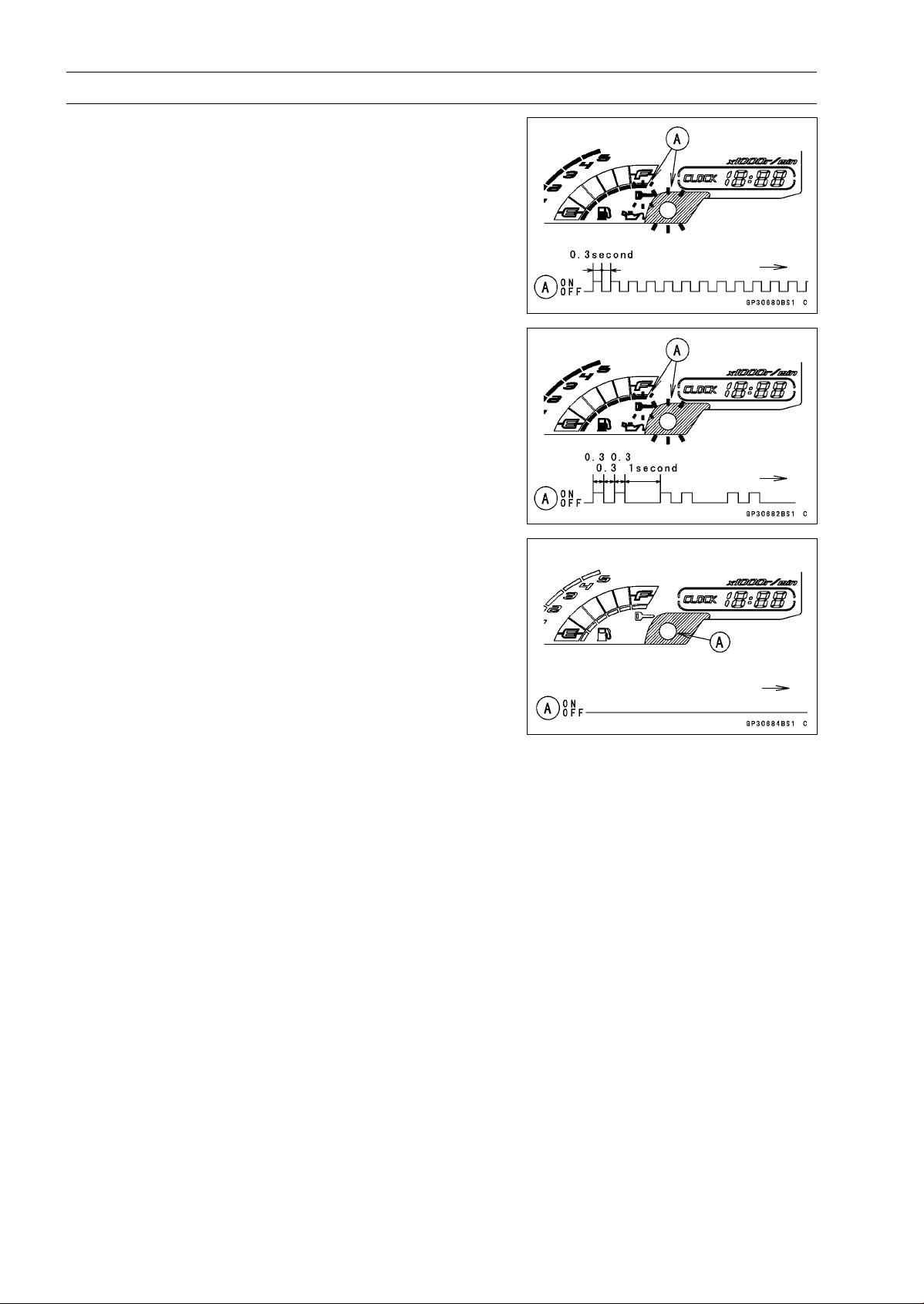
16-114 ELECTRICAL SYSTEM
Immobilizer System (Equipped Models), ZR1000DB ∼/EB ∼
Ignition Key Collation Error
•
The second ignition key is registered in the ECU.
○
The warning indicator light (LED) and the immobilizer
warning symbol [A] blinks 2 time and stops for 1 second
and the repeats this cycle to indicate successful registra-
tion of the second ignition key.
•
Turn OFF the ignition switch and wait for period more than
15 seconds.
•
The registration mode automatically ends.
●The warning indicator light (LED) [A] goes off.
NOTE
○
Turn the ignition switch ON with the registered ignition
key.
○
Check that the engine can be started using all regis-
tered ignition keys.
Case 5: When replacing the antenna.
•
Prepare a new antenna.
•
Refer to the Immobilizer System Parts Replacement.
NOTE
○
No key registration is required.
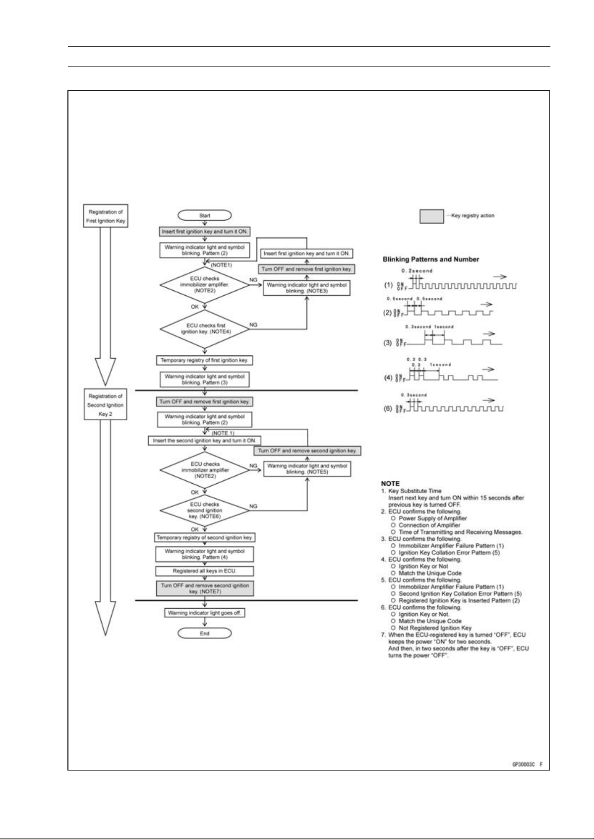
ELECTRICAL SYSTEM 16-115
Immobilizer System (Equipped Models), ZR1000DB ∼/EB ∼
All Keys Initial Registration Flow Chart
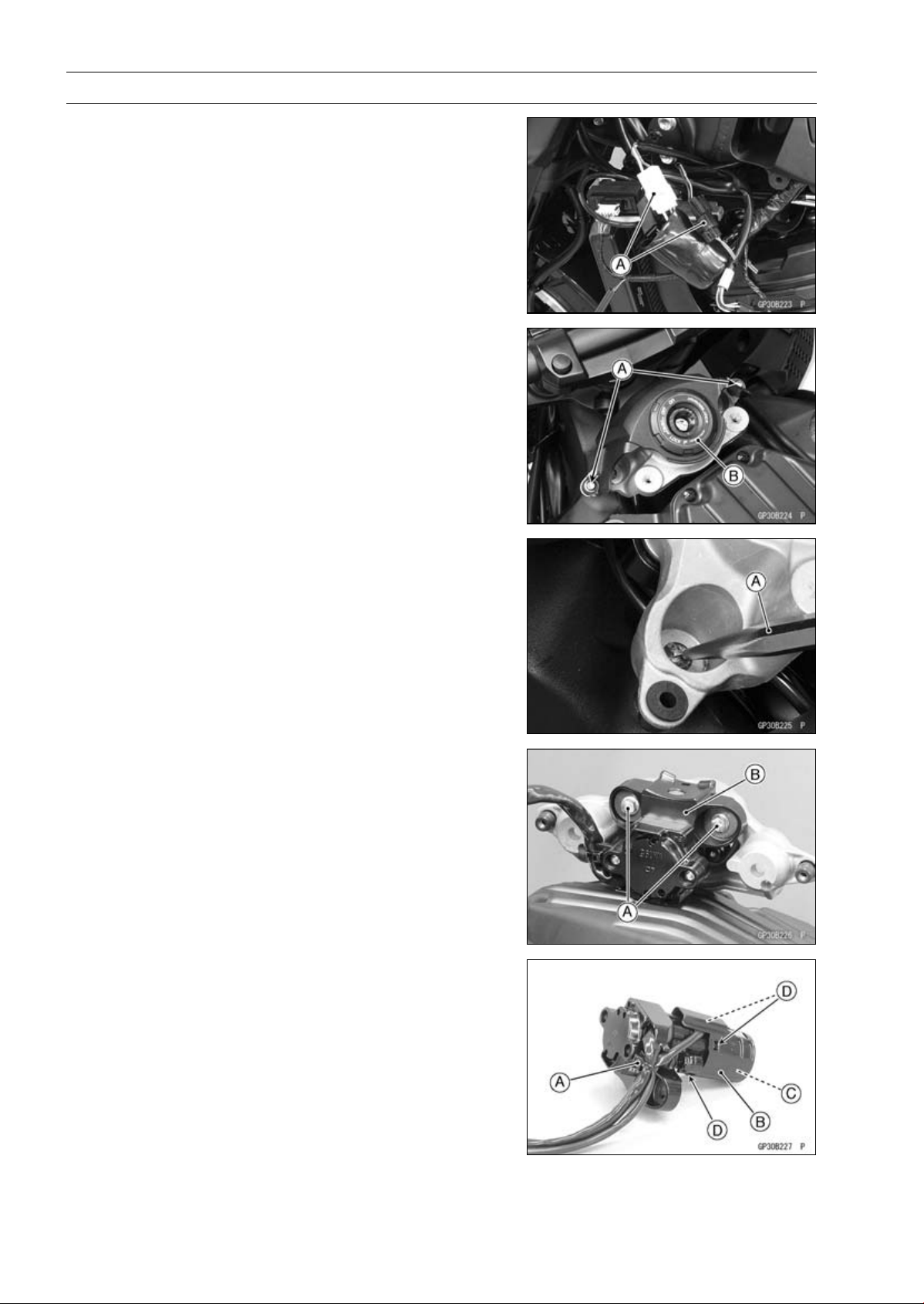
16-116 ELECTRICAL SYSTEM
Immobilizer System (Equipped Models), ZR1000DB ∼/EB ∼
Immobilizer System Parts Replacement
Immobilizer Antenna Replacement
•
Remove:
Fuel Tank (see Fuel Tank Removal in the Fuel System
(DFI) chapter)
Left Center Fairing (see Center Fairing Removal in the
Frame chapter)
•
Disconnect the lead connectors [A].
•
Remove:
Bolts [A]
Ignition Switch Cover [B]
•
Using a small chisel [A] or punch, turn out the Torx bolts.
•
Remove:
Bolts [A]
Ignition Switch [B]
•
Cut the band [A].
•
Remove the antenna cover [B] to take out the antenna
[C].
○
Clear the projections [D] of the ignition switch to remove
the cover.
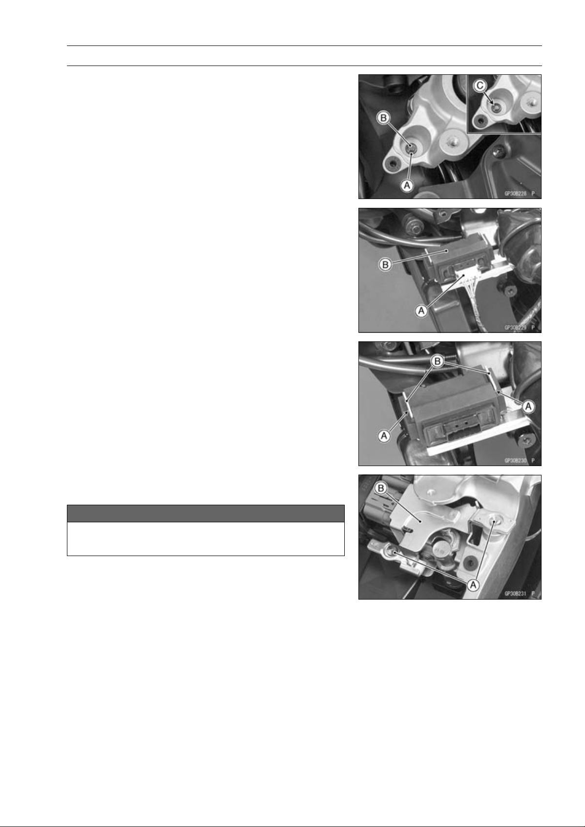
ELECTRICAL SYSTEM 16-117
Immobilizer System (Equipped Models), ZR1000DB ∼/EB ∼
•
Tighten a new Torx bolt [A] until the bolt head [B] is broken
[C].
•
Run the leads correctly (see Cable, Wire, and Hose Rout-
ing section in the Appendix chapter).
Immobilizer Amplifier Replacement
•
Remove:
Left Center Fairing (see Center Fairing Removal in the
Frame chapter)
Immobilizer Amplifier connector [A]
Immobilizer Amplifier [B]
•
Fit the slits [A] on the damper to the bracket projections
[B].
ECU (Electronic Control Unit) Replacement (for Immo-
bilizer Models)
NOTICE
Never drop the ECU, especially on a hard surface.
Such a shock to the ECU can damage it.
•
Remove:
Seat Cover (see Seat Cover Removal in the Frame
chapter)
•
Using a small chisel or other suitable tool, remove the
screws [A] and ECU guard [B].
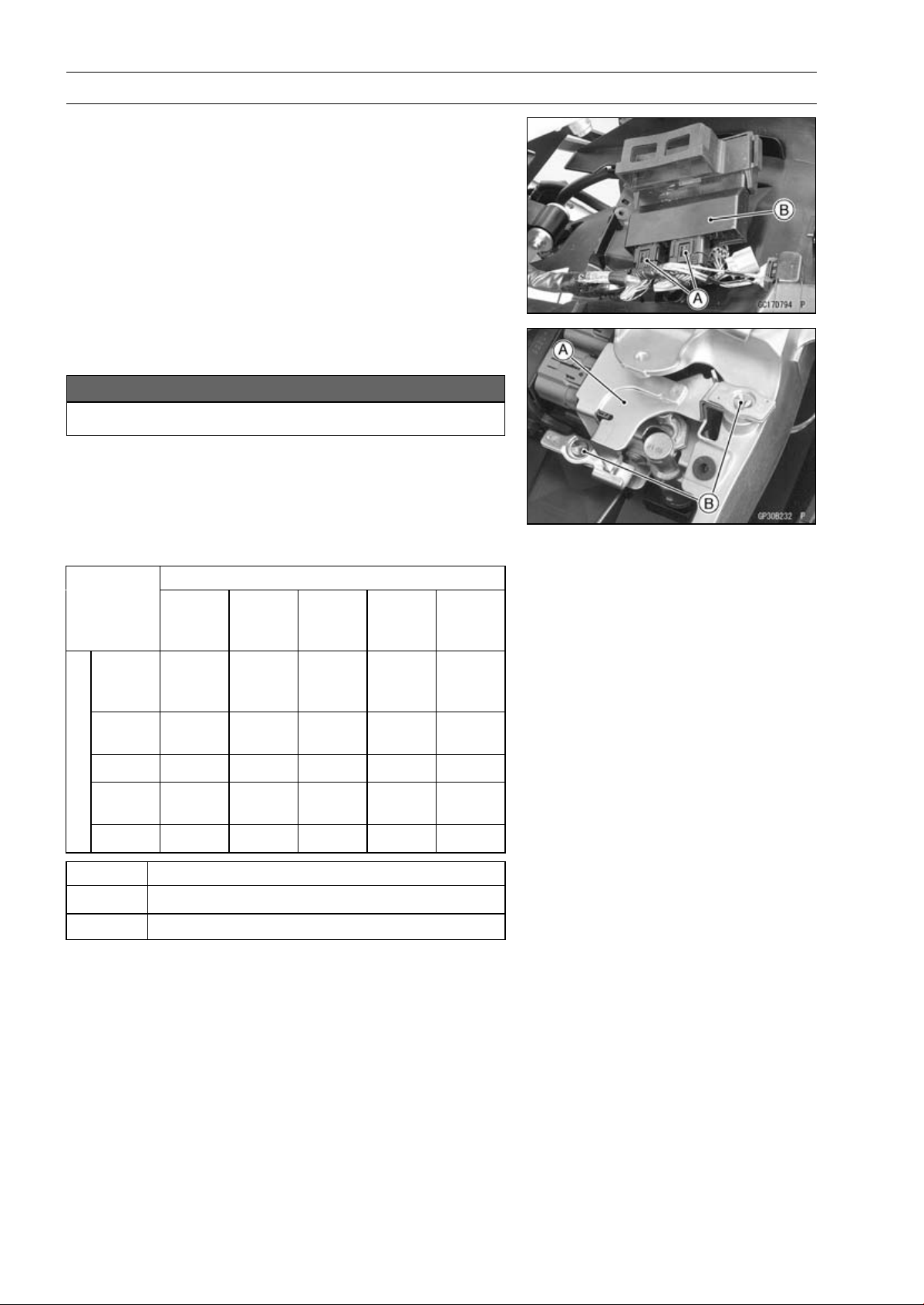
16-118 ELECTRICAL SYSTEM
Immobilizer System (Equipped Models), ZR1000DB ∼/EB ∼
•
Remove:
Relay Box (see Relay Box Removal)
ECU Connectors [A]
ECU [B]
•
Connect the connectors to the ECU.
•
Install the ECU guard [A].
NOTICE
Do not pinch the leads.
•
Tighten the new screws [B] using the Kawasaki genuine
screws of which threads are coated with locking agent.
Immobilizer Relational Parts Replacement Chart
Failed or Lost Part
Ignition
Key
(Black)
Ignition
Switch
Antenna
Ampli-
fier
ECU
Ignition
Key
(Black)
•
○
Ignition
Switch
•
Antenna
•
Ampli-
fier
•
*
ECU
○
•
*
Replacement Part
•
Main Replacement Part
○
Additional Replacement Part
Immobilizer System Inspection
•
Refer to the Immobilizer Amplifier and Blank Key Detec-
tion section in the Fuel System (DFI) chapter.
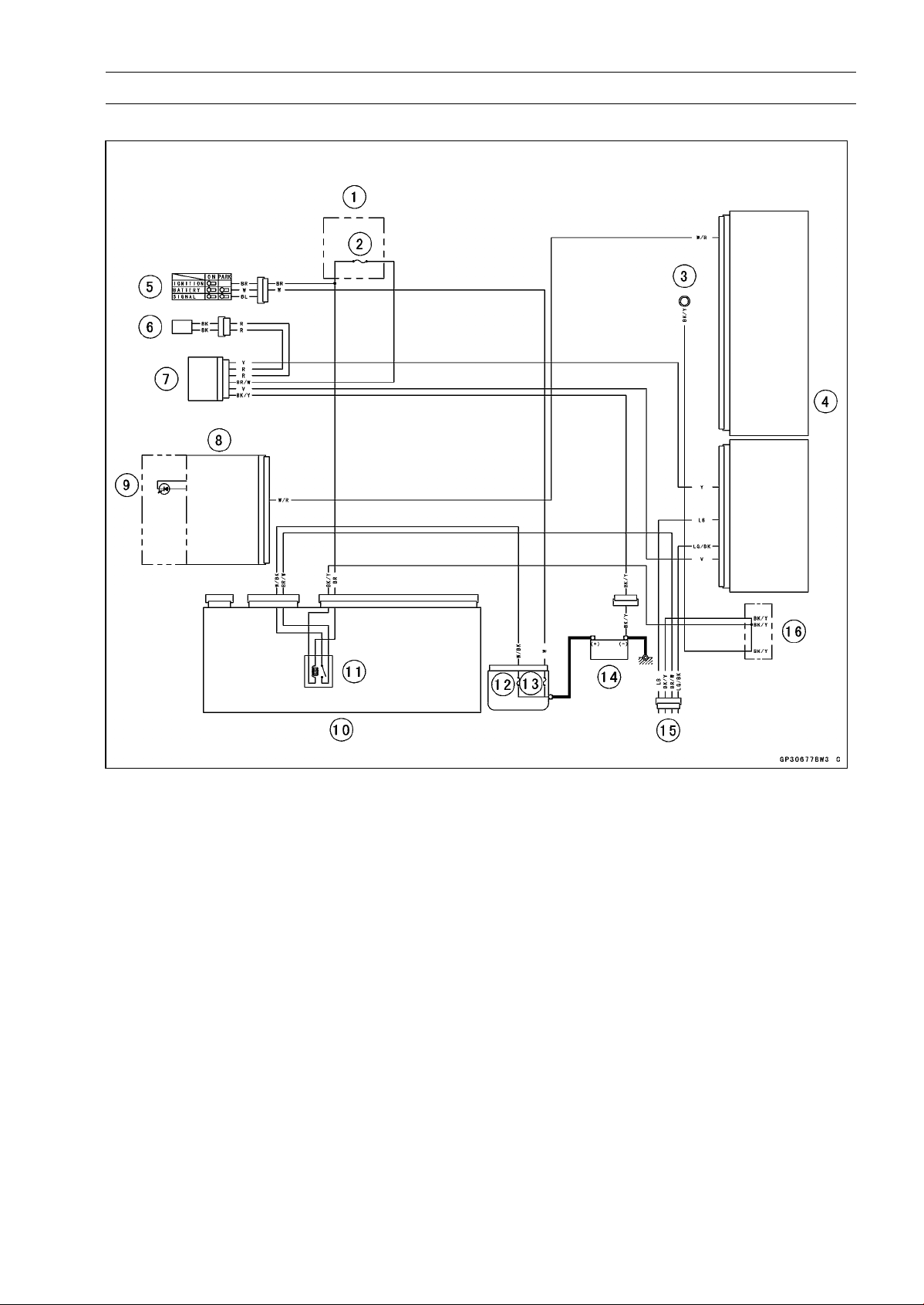
ELECTRICAL SYSTEM 16-119
Immobilizer System (Equipped Models)
Immobilizer System Circuit
1. Fuse Box
2. Ignition Fuse 15 A
3. Meter Ground
4. ECU
5. Ignition Switch
6. Immobilizer Antenna
7. Immobilizer Amplifier
8. Meter Unit
9. Oil Pressure/FI/Immobilizer Warning Indicator Light (LED)
10. Relay Box
11. ECU Main Relay
12. FI Fuse 15 A
13. Main Fuse 30 A
14. Battery 12 V 8 Ah
15. Immobilizer/Kawasaki Diagnostic System Connector
16. Water-proof Joint C
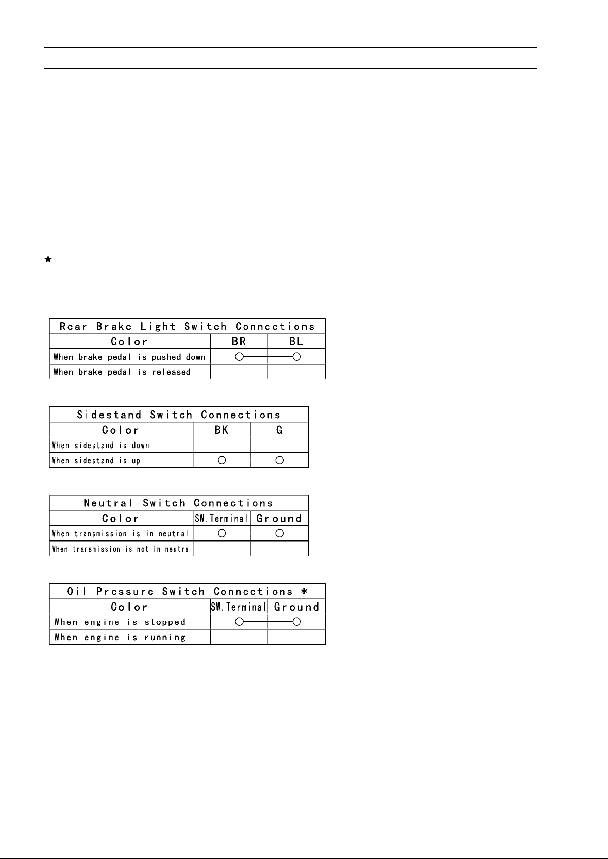
16-120 ELECTRICAL SYSTEM
Switches and Sensors
Brake Light Timing Inspection
•
Refer to the Brake Light Switch Operation Inspection in
the Periodic Maintenance chapter.
Brake Light Timing Adjustment
•
Refer to the Brake Light Switch Operation Inspection in
the Periodic Maintenance chapter.
Switch Inspection
•
Using a hand tester, check to see that only the con-
nections shown in the table have continuity (about zero
ohms).
○
For the switch housings and the ignition switch, refer to
the tables in the Wiring Diagram.
If the switch has an open or short, repair it or replace it
with a new one.
Special Tool - Hand Tester: 57001-1394
Rear Brake Light Switch Connections
Sidestand Switch Connections
Neutral Switch Connections
Oil Pressure Switch Connections*
*: Engine lubrication system is in good condition.
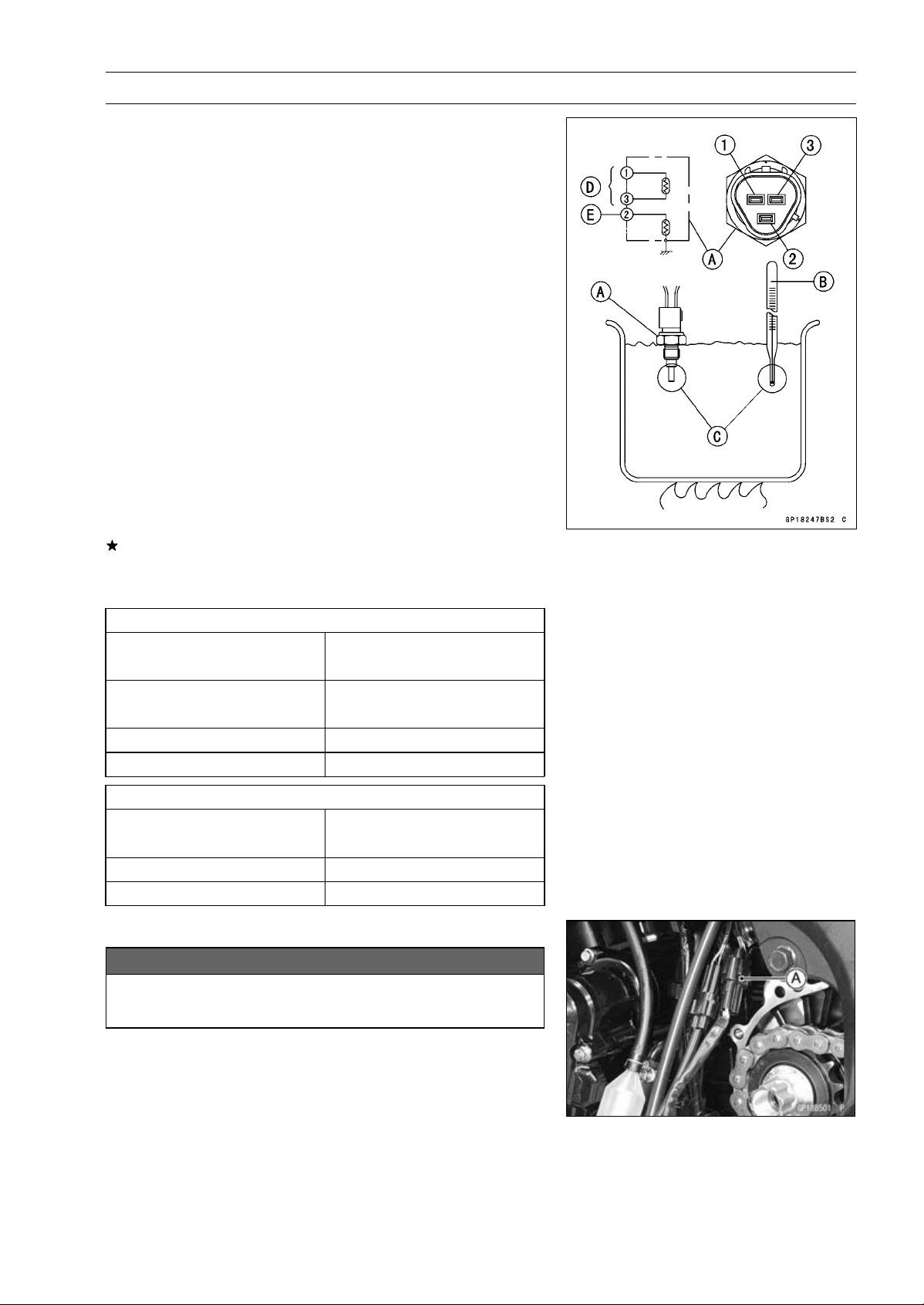
ELECTRICAL SYSTEM 16-121
Switches and Sensors
Water Temperature Sensor Inspection
•
Remove the water temperature sensor (see Water Tem-
perature Sensor Removal/Installation in the Fuel System
(DFI) chapter).
•
Suspend the sensor [A] in a container of coolant so that
the threaded portion is submerged.
•
Suspend an accurate thermometer [B] with temperature
sensing portions [C] located in almost the same depth.
NOTE
○
The sensor and thermometer must not touch the con-
tainer side or bottom.
•
Place the container over a source of heat and gradu-
ally raise the temperature of the coolant while stirring the
coolant gently.
•
Using the hand tester, measure the internal resistance of
the sensor.
○
The sensor sends electric signals to the ECU and coolant
temperature gauge in the meter unit.
○
Measure the resistance across the terminals and the body
(for the gauge) at the temperatures shown in the table.
If the hand tester does not show the specified values, re-
place the sensor.
Water Temperature Sensor
Resistance for ECU [D]
Resistance (kΩ)
Temperature
(Terminal [1]-[3])
+ 0.155
20°C (68°F)
2.46
–0.143
80°C (176°F)
0.32 ±0.011
110°C (230°F)
0.1426 ±0.0041
Resistance for Water Temperature Gauge [E]
Resistance (Ω)
Temperature
(Terminal [2]-Body)
50°C (122°F)
210 ±40
120°C (248°F)
21.2 ±1.5
Speed Sensor Removal
NOTICE
Never drop the sensor especially on a hard surface.
Such a shock to the sensor can damage it.
•
Remove:
Speed Sensor Connector (Disconnect) [A]
Engine Sprocket Cover (see Engine sprocket Cover Re-
moval in the Final Drive chapter)
Speed Sensor
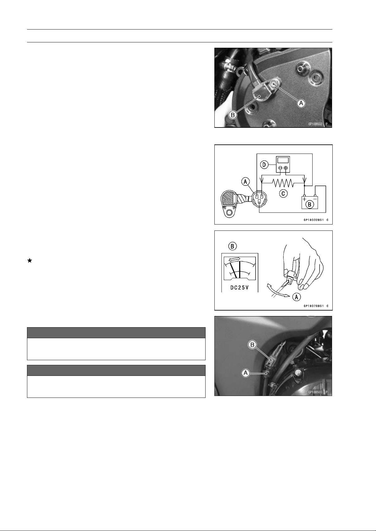
16-122 ELECTRICAL SYSTEM
Switches and Sensors
Speed Sensor Installation
•
Apply a non-parmanent locking agent to the speed sensor
mounting bolt [A].
•
Install the speed sensor [B] to the inner engine sprocket
cover.
•
Tighten:
Torque - Speed Sensor Mounting Bolt: 6.9 N·m (0.70 kgf·m,
61 in·lb)
•
Install the engine sprocket cover (see Engine Sprocket
Cover Installation in the Final Drive chapter).
•
Connect the speed sensor lead connector.
Speed Sensor Inspection
•
Remove the speed sensor (see Speed Sensor Removal).
•
Connect the speed sensor connector [A] with the battery
[B], 10 kΩ resistor [C] and hand tester [D] as shown in the
figure.
•
Set the tester to the DC 25 V range.
Special Tool - Hand Tester: 57001-1394
•
Trace [A] of the speed sensor surface with the screw-
driver.
○
Then the tester indicator should flick [B].
If the tester indicator does not flick, replace the speed
sensor.
Oxygen Sensor Removal (Equipped Models)
NOTICE
Never drop the sensor especially on a hard surface.
Such a shock to the sensor can damage it.
NOTICE
Do not pull strongly, twist, or bend the oxygen sen-
sor lead. This may cause the wiring open.
•
Clear the oxygen sensor lead from the clamp [A].
•
Disconnect the oxygen sensor lead connector [B].
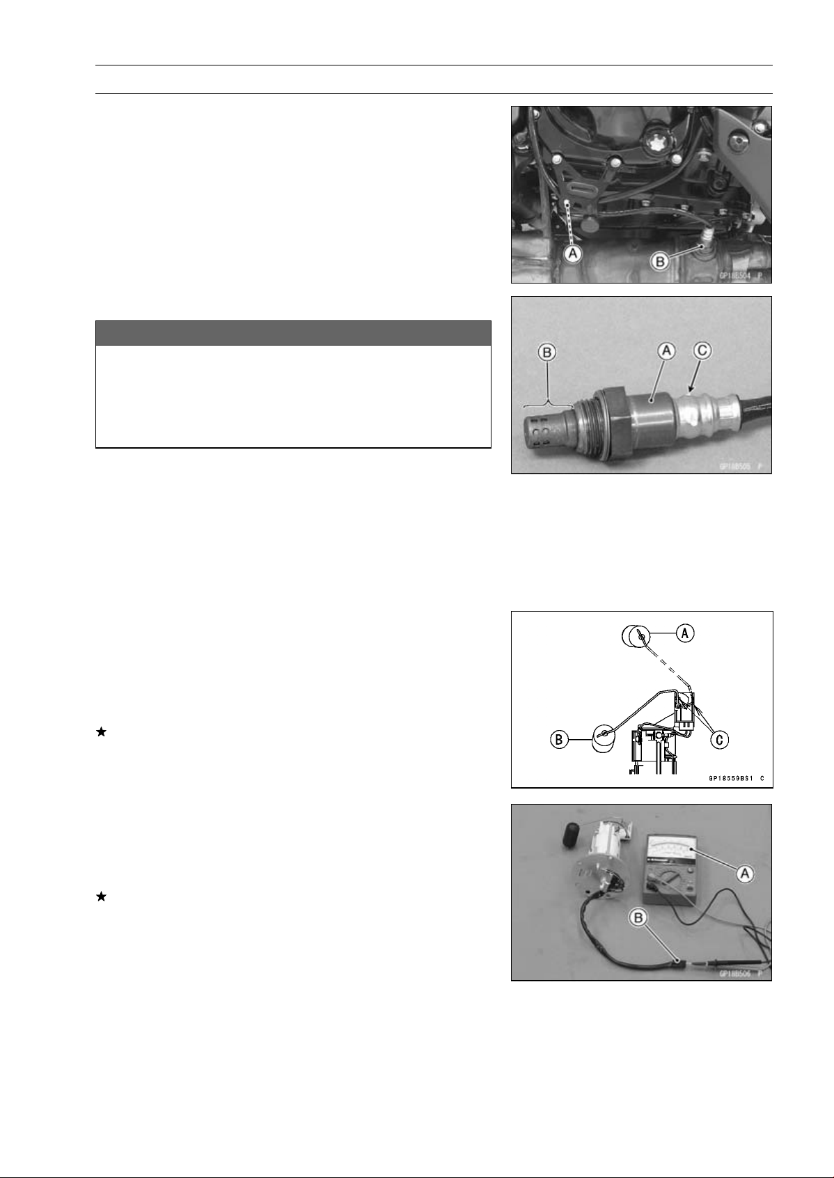
ELECTRICAL SYSTEM 16-123
Switches and Sensors
•
Clear the oxygen sensor lead from the clamp [A].
•
Remove the oxygen sensor [B].
Oxygen Sensor Installation (Equipped Models)
NOTICE
Never drop the oxygen sensor [A] especially on a
hard surface. Such a shock to the unit can damage
it. Do not touch the sensing part [B] and filter holes
[C] of the sensor to prevent oil contact. Oil contami-
nation from hands can reduce sensor performance.
•
Tighten:
Torque - Oxygen Sensor: 44 N·m (4.5 kgf·m, 32 ft·lb)
•
Run the oxygen sensor lead correctly (see Cable, Wire,
and Hose Routing section in the Appendix chapter).
Oxygen Sensor Inspection (Equipped Models)
•
Refer to the Oxygen Sensor Inspection in the Fuel System
(DFI) chapter.
Fuel Level Sensor Inspection
•
Remove:
Fuel Pump (see Fuel Pump Removal in the Fuel System
(DFI) chapter)
•
Check that the float moves up and down smoothly without
binding. It should go down under its own weight.
If the float does not move smoothly, replace the fuel pump.
Float in Full Position [A]
Float in Empty Position [B]
Float Arm Stoppers [C]
•
Using the hand tester [A], measure the resistance across
the terminals in the fuel level sensor lead connector [B].
Special Tools - Hand Tester: 57001-1394
Needle Adapter set: 57001-1457
If the tester readings are not as specified, or do not
change smoothly according as the float moves up and
down, replace the fuel pump.
Fuel Level Sensor Resistance
Standard: Full position: 9.6
∼ 12.4
Empty position: 222
∼ 228
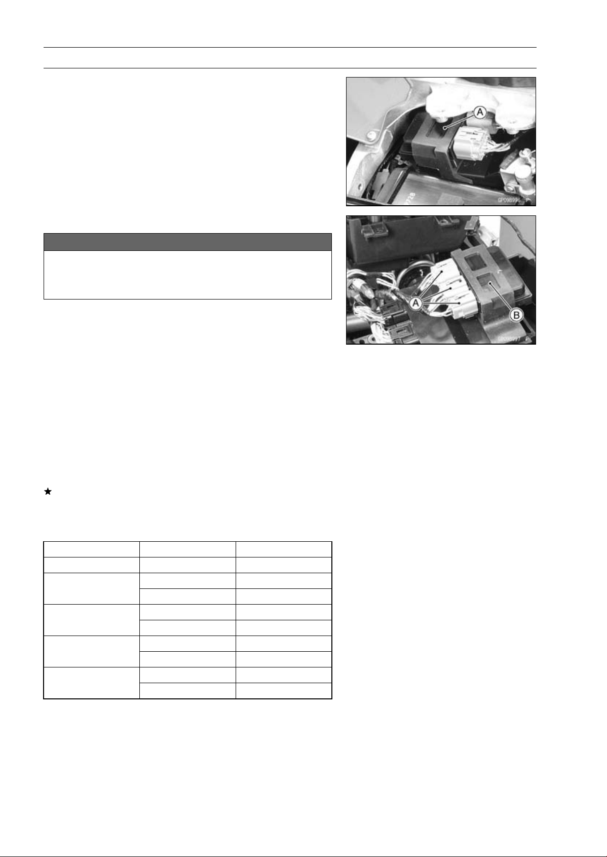
16-124 ELECTRICAL SYSTEM
Relay Box
The relay box [A] has relays and diodes. The relays and
diodes can not be removed.
Relay Box Removal
NOTICE
Never drop the relay box especially on a hard sur-
face.
Such a shock to the relay box can damage it.
•
Remove the rear fender from the battery case and rear
frame (see Flap and Rear Fender Removal in the Frame
chapter).
•
Disconnect:
Connectors [A]
•
Remove:
Relay Box [B]
Relay Circuit Inspection
•
Remove the relay box (see Relay Box Removal).
•
Check conductivity of the following numbered terminals
by connecting the hand tester and one 12 V battery to the
relay box as shown (see Relay Box Internal Circuit in this
section).
If the tester does not read as specified, replace the relay
box.
Relay Circuit Inspection (with the battery disconnected)
Tester Connection Tester Reading (Ω)
Headlight Relay 1-3
∞
7-6
∞
ECU Main Relay
4-5
Not ∞*
7-8
∞
Fuel Pump Relay
9-10
Not ∞*
11-16
∞
Starter Circuit Relay
11-12
∞
17-20
∞
Fan Relay
18-19
Not ∞*
*: The actual reading varies with the hand tester used.
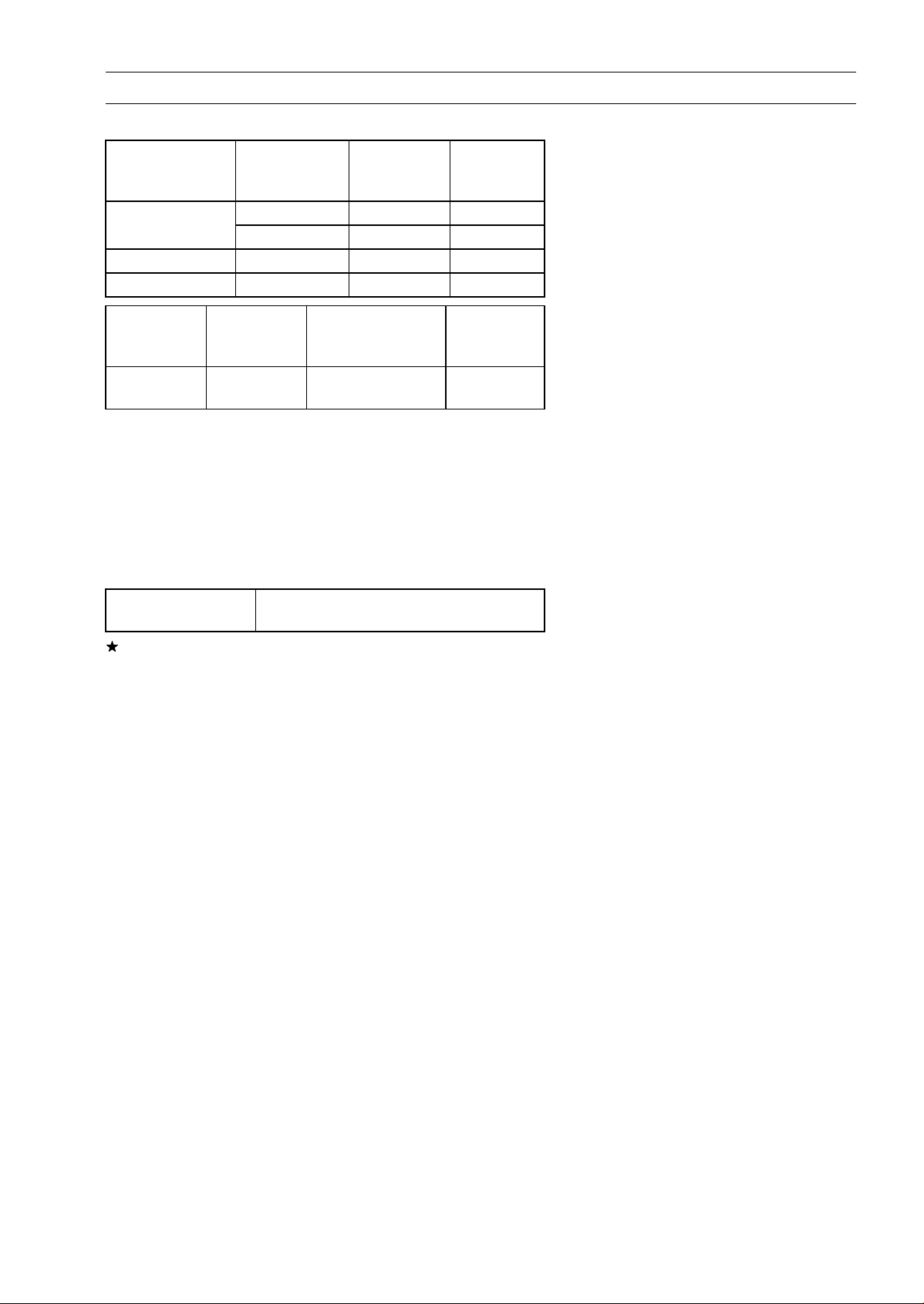
ELECTRICAL SYSTEM 16-125
Relay Box
Relay Circuit Inspection (with the battery connected)
Battery
Connection
(+) (–)
Tes ter
Connection
Tes ter
Reading (Ω)
2-11 1-3 0
ECU Main Relay
4-5 7-6 0
Fuel Pump Relay 9-10 7-8 0
Fan Relay 18-19 17-20 0
Battery
Connection
(+) (–)
Tester Connection
DC 25 V Range
(+) (–)
Tes ter
Reading (V)
Starter
Circuit Relay
16-12 11-12
Battery
Voltage
(+): Apply positive lead.
(–): Apply negative lead.
Diode Circuit Inspection
•
Remove the relay box (see Relay Box Removal).
•
Check conductivity of the following pairs of terminals (see
Relay Box Internal Circuit in this section).
Diode Circuit Inspection
Tester Connection
1-11, 2-11, 12-13, 12-15, 12-16, 13-14,
13-15
The resistance should be low in one direction and more
than ten times as much in the other direction. If any diode
shows low or high in both directions, the diode is defective
and the relay box must be replaced.
NOTE
○
The actual meter reading varies with the meter or tester
used and the individual diodes, but generally speaking,
the lower reading should be from zero to one half the
scale.
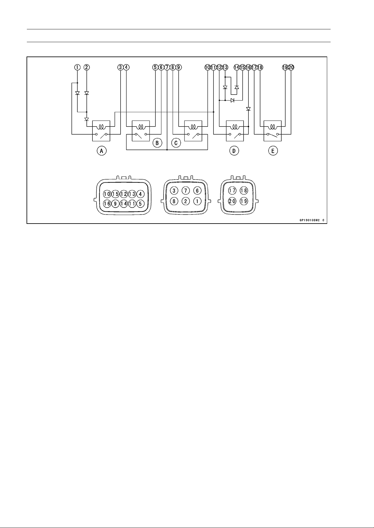
16-126 ELECTRICAL SYSTEM
Relay Box
Relay Box Internal Circuit
A: Headlight Relay
B: ECU Main Relay
C: Fuel Pump Relay
D: Starter Circuit Relay
E: Fan Relay
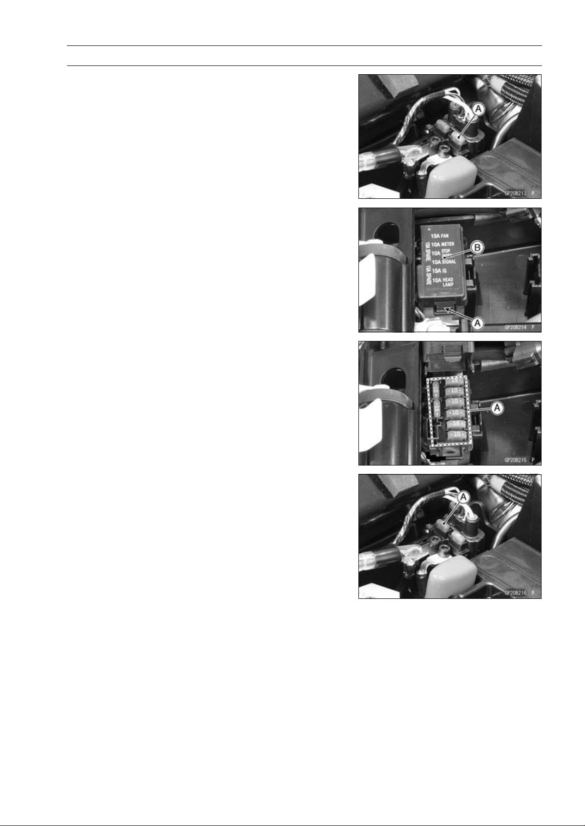
ELECTRICAL SYSTEM 16-127
Fuse
30 A Main Fuse Removal
•
Remove:
Starter Cable Terminal Cover (see Starter Relay Inspec-
tion)
•
Pull out the main fuse [A] from the starter relay with a
needle nose pliers.
Fuse Box Fuse Removal
•
Remove:
Front Seat (see Front Seat Removal in the Frame chap-
ter)
•
Unlock the hook [A] to lift up the lid [B].
•
Pull the fuses [A] straight out of the fuse box with needle
nose pliers.
15 A FI Fuse Removal
•
Remove:
Starter Cable Terminal Cover (see Starter Relay Inspec-
tion )
•
Pull out the fuse [A].
Fuse Installation
•
If a fuse fails during operation, inspect the electrical sys-
tem to determine the cause, and then replace it with a
new fuse of proper amperage.
•
Install the fuse box fuses on the original position as spec-
ified on the lid.
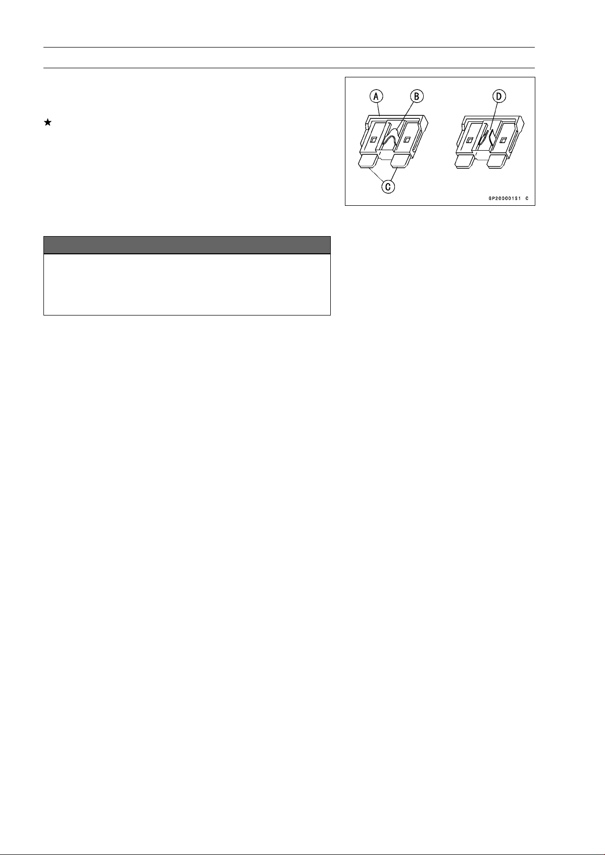
16-128 ELECTRICAL SYSTEM
Fuse
Fuse Inspection
•
Remove the fuse.
•
Inspect the fuse element.
If it is blown out, replace the fuse. Before replacing a
blown fuse, always check the amperage in the affected
circuit. If the amperage is equal to or greater than the
fuse rating, check the wiring and related components for
a short circuit.
Housing [A]
Fuse Element [B]
Terminals [C]
Blown Element [D]
NOTICE
When replacing a fuse, be sure the new fuse
matches the specified fuse rating for that circuit.
Installation of a fuse with a higher rating may cause
damage to wiring and components.

APPENDIX 17-1
17
Appendix
Table of Contents
Cable, Wire, and Hose Routing .............................................................................................. 17-2
Troubleshooting Guide ........................................................................................................... 17-66
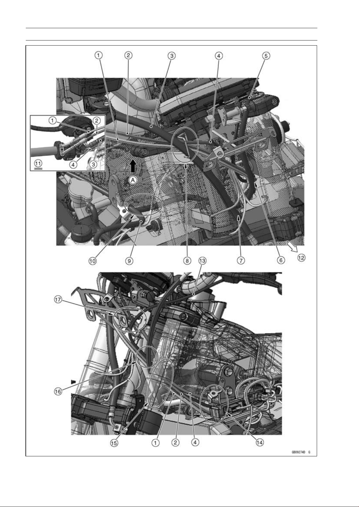
17-2 APPENDIX
Cable, Wire, and Hose Routing

APPENDIX 17-3
Cable, Wire, and Hose Routing
1. Throttle Cable (Accelerator)
2. Throttle Cable (Decelerator)
3. Brake Hose
4. Right Switch Housing Lead
5. Clutch Cable
6. Run the clutch cable to the front side of the other leads and cables.
7. Run the brake hose to the rear side of the headlight lead.
8. Run the brake hose to the most outside of the other leads and cables through the clamp.
9. Hold the horn lead and front right turn signal light lead with the clamp.
10. Run the clutch cable under the reserve tank overflow hose and leads.
11. Viewed from A
12. Front
13. Left Switch Housing Lead
14. Run the left and right switch housing leads, headlight leads, and throttle cables to the inside of
the upper engine bracket.
15. Run the left and right switch housing leads and main harness through the bracket so that the
main harness comes to the most lower side of the other lead. Run the clutch cable and throttle
cables to the outside of the clamp in order from the outside of the frame.
16. Run the clutch cable, throttle cables, and other leads in order from the front of the frame.
17. Run the throttle cables, left and right switch housing leads, and meter lead through the upper
fairing bracket.
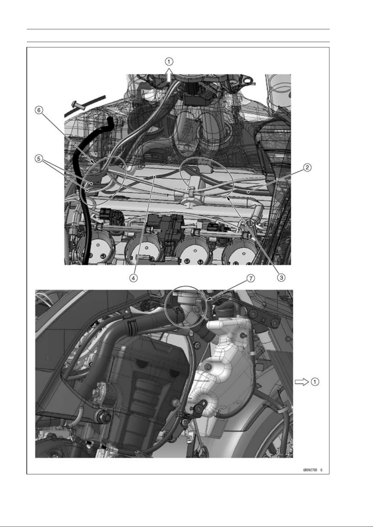
17-4 APPENDIX
Cable, Wire, and Hose Routing

APPENDIX 17-5
Cable, Wire, and Hose Routing
1. Front
2. Clutch Cable
3. Run the clutch cable under the radiator fan motor lead, horn lead, and front right turn signal light
lead.
4. Radiator Fan Motor Lead
5. Throttle Cables
6. Run the throttle cables under the main harness.
7. Run the clutch cable to the inside of the frame from the rear side of the upper engine bracket.
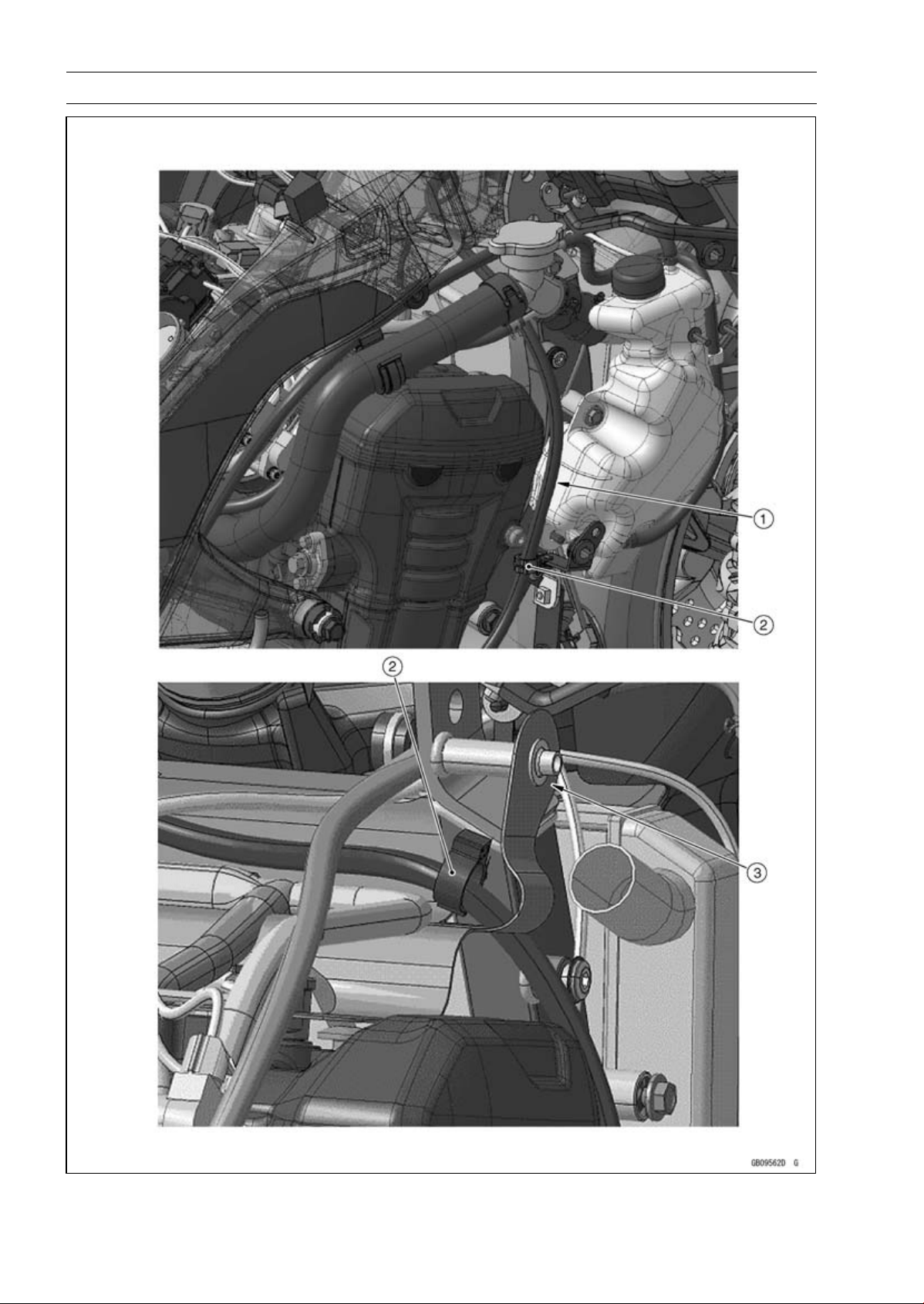
17-6 APPENDIX
Cable, Wire, and Hose Routing

APPENDIX 17-7
Cable, Wire, and Hose Routing
1. Run the clutch cable to the rear side of the coolant reserve tank as shown.
2. Hold the clutch cable with the clamp.
3. Hook the heat insulation rubber plate to the boss of the upper engine bracket.
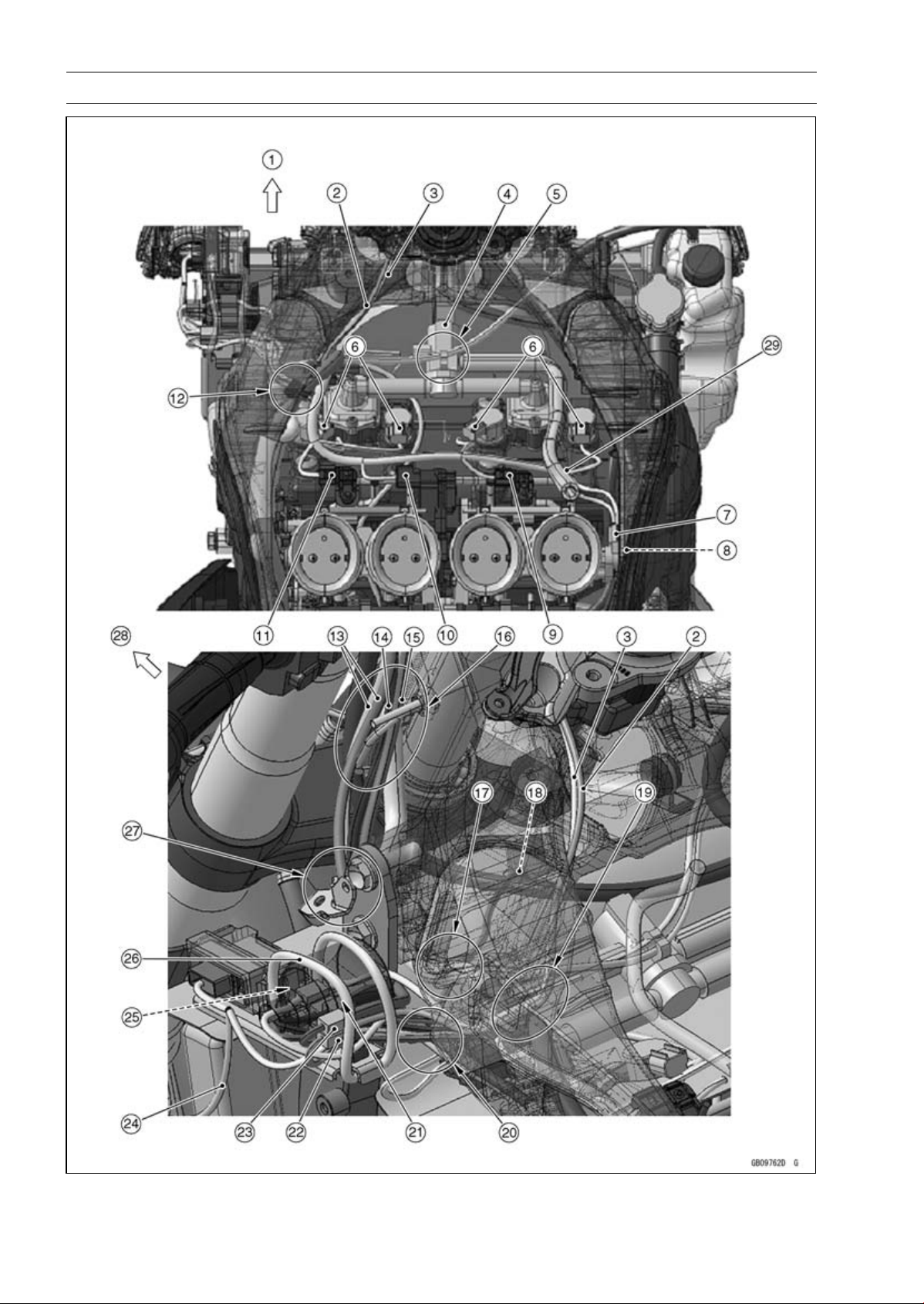
17-8 APPENDIX
Cable, Wire, and Hose Routing

APPENDIX 17-9
Cable, Wire, and Hose Routing
1. Front
2. Immobilizer Antenna Lead (Equipped Models)
3. Ignition Switch Lead
4. Air Switching Valve
5. Run the horn lead and front right turn signal light lead through the clamp of the air switching
valve.
6. Stick Coil Connectors
7. Subthrottle Sensor Connector
8. Main Throttle Sensor Connector
9. Intake Air Pressure Sensor #2 Connector
10. Subthrottle Valve Actuator Connector
11. Intake Air Pressure Sensor #1 Connector
12. Insert the clamp of the main harness to the hole of the frame.
13. Throttle Cables
14. Left Switch Housing Lead
15. Right Switch Housing Lead
16. Run the left and right switch housing leads and main harness through the bracket so that the
main harness comes to the most lower side of the other lead.
17. Run the radiator fan motor lead under the main harness.
18. Radiator Fan Motor Lead
19. Run the ignition switch lead and immobilizer antenna lead (equipped models) to the upside of
the main harness.
20. Run the left and right switch housing leads, immobilizer antenna lead (equipped models), and
ignition switch lead to the upside of the throttle cables and to the outside of the frame.
21. Run the subharness to the rear side of the fan motor lead.
22. Immobilizer Antenna Lead Connector (Equipped Models)
23. Right Switch Housing Lead Connector
24. Front Left Turn Signal Light Lead
25. Insert the connectors of the left switch housing lead, ignition switch lead, and fan motor lead to
the rubber cover.
26. Hold the rubber cover, immobilizer amplifier (equipped models) and front left turn signal light
lead, immobilizer antenna lead connector (equipped models), ignition switch lead, and right
switch housing lead connector with the band.
27. Run the throttle cable, left and right switch housing leads, and main harness to the inside of the
upper engine bracket.
28. Front
29. Run the air cleaner breather hose above the main harness.
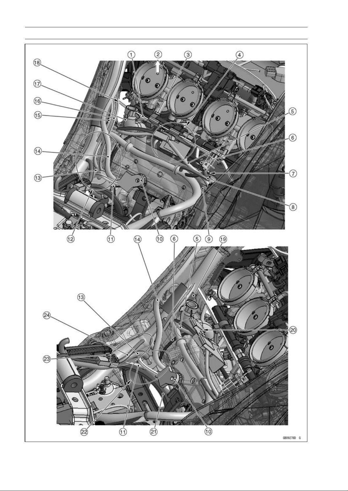
17-10 APPENDIX
Cable, Wire, and Hose Routing

APPENDIX 17-11
Cable, Wire, and Hose Routing
1. Fuel Injector Lead
2. Front
3. Hold the fuel injector lead with the clamp.
4. Hold the alternator lead and crankshaft sensor lead with the bracket.
5. Crankshaft Sensor Lead
6. Alternator Lead
7. Run the intake air temperature sensor to the upside of the crankshaft sensor lead.
8. Intake Air Temperature Sensor Lead
9. Oxygen Sensor Lead (Equipped Models)
10. Frame Ground
11. Starter Motor Cable
12. Run the fuel tank drain hose and fuel tank breather hose (other than CAL, SEA-B1 and TH
models) to the rear side of the sidestand switch lead and speed sensor lead, to the front side of
the frame ground leads, to the inside of the battery negative (–) lead, and to the outside of the
starter motor cable.
13. Fuel Tank Breather Hose (other than CAL, SEA-B1 and TH Models)
14. Fuel Tank Drain Hose
15. Speed Sensor Lead
16. Sidestand Switch Lead
17. Breather Hose
18. Run the fuel injection lead to the front side of the breather hose.
19. Install the damper so that the damper end fits the separating portion of the main harness as
shown.
20. Run the alternator lead and crankshaft sensor lead to the rear side of the breather hose.
21. Battery Negative (–) Cable
22. Run the alternator lead to the front side of the frame ground leads. Run the battery negative (–)
cable and starter motor cable to the rear side of the frame ground leads.
23. Run the battery negative (–) lead to the outside of the fuel tank breather hose (other than CAL,
SEA-B1 and TH models) and fuel tank drain hose.
24. Battery Negative (–) Lead
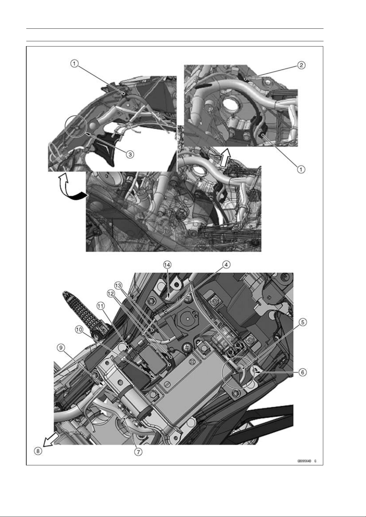
17-12 APPENDIX
Cable, Wire, and Hose Routing

APPENDIX 17-13
Cable, Wire, and Hose Routing
1. Insert the clamps of the main harness to the ribs of the inside of the frame.
2. Hold the rear brake light switch connector with the clamp.
3. Run the main harness under the pin.
4. Hold the fuel pump lead (main harness side) with the clamp and insert it to the battery case.
5. Starter Motor Cable
6. Run the starter motor cable to the upside of the main harness, between the starter relay and
battery, and to the left side of the battery positive (+) cable.
7. Hold the regulator/rectifier lead to the battery case with the clamp.
8. Front
9. Run the main harness to the inside at front of battery case.
10. Run the exhaust butterfly valve actuator leads between the fuse box and the battery.
11. Run the fuel pump lead to the upside of the exhaust butterfly valve cables, to the outside of the
fuse box, and to under the fuel tank bracket.
12. Exhaust Butterfly Valve Actuator Leads
13. Exhaust Butterfly Valve Cables
14. Run the main harness to the outside at rear of battery case.
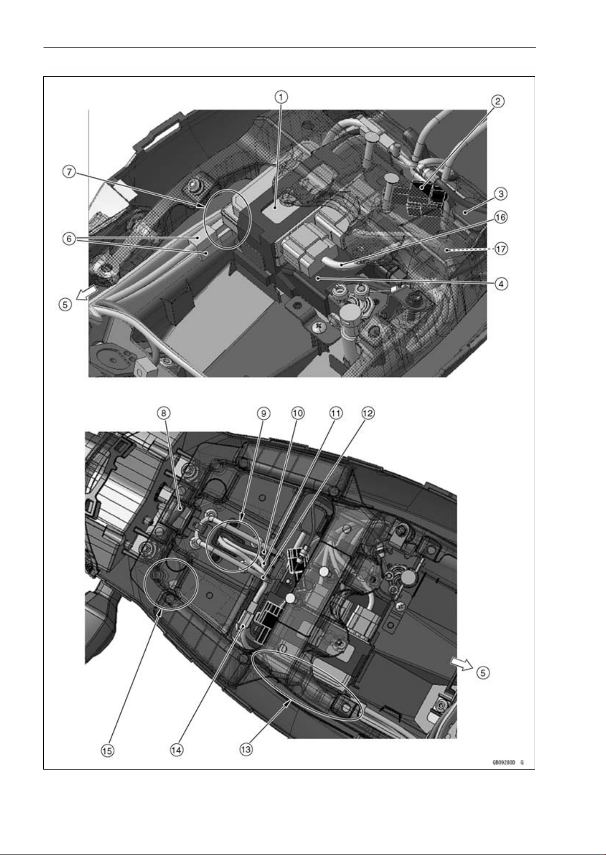
17-14 APPENDIX
Cable, Wire, and Hose Routing

APPENDIX 17-15
Cable, Wire, and Hose Routing
1. Relay Box
2. Kawasaki Diagnostic System Connector
3. Turn Signal Relay
4. ECU
5. Front
6. Rear Left and Right Turn Signal Light Lead Connectors
7. Run the main harness and rear left and right turn signal light leads between the rear fender and
the ECU.
8. Tail/Brake Light (LED) Lead
9. Run the rear left and right turn signal light leads and license plate light lead through the hole.
10. Rear Right Turn Signal Light Lead
11. Rear Left Turn Signal Light Lead
12. License Plate Light Lead
13. Run the leads and harnesses between the rear frame and the ECU.
14. License Plate Light Lead Connector
15. Run the tail/brake light (LED) lead between the rear fender and the rear frame.
16. Run this relay box connector lead to the upside of the other relay box connector leads.
17. Put the water-proof joint under the relay box connector leads and front side of the turn signal
relay.

17-16 APPENDIX
Cable, Wire, and Hose Routing

APPENDIX 17-17
Cable, Wire, and Hose Routing
1. Front
2. Rear Brake Light Switch Lead
3. Crankshaft Sensor Lead
4. Hold the rear brake light switch lead, crankshaft sensor lead, and oxygen sensor lead (equipped
models) with the clamp.
5. Oxygen Sensor Lead (Equipped Models)
6. Hold the oxygen sensor lead (equipped models) and crankshaft sensor lead with the clamp, and
vend it to the rear side of the frame.
7. Run the rear brake light switch lead through the clamp and to the outside of the exhaust butterfly
valve cables.
8. Exhaust Butterfly Valve Cables
9. Regulator/Rectifier Lead
10. Hold the regulator/rectifier lead with the clamp.
11. Front Right Turn Signal Light Lead
12. Brake Hose
13. Meter Lead
14. Front Left Turn Signal Light Lead
15. Run the left switch housing lead through the left side of the upper fairing bracket. Run the right
switch housing lead, meter lead, and throttle cables through the right side of the upper fairing
bracket.
16. Left Headlight Lead
17. City Light Lead
18. Right Headlight Lead with Green Tape
19. Hold the front right turn signal light lead and horn lead with the clamp.
20. Run the right switch housing lead, throttle cables, and brake hose through the clamp.
21. Throttle Cables
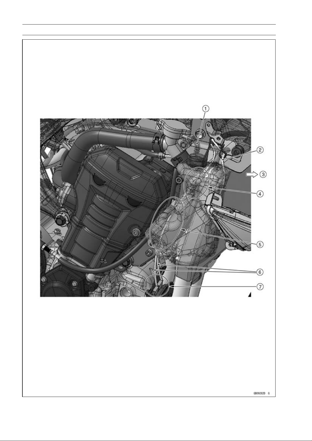
17-18 APPENDIX
Cable, Wire, and Hose Routing

APPENDIX 17-19
Cable, Wire, and Hose Routing
1. Reserve Tank Hose
2. Front Right Turn Signal Light Lead
3. Front
4. Run the horn lead under the reserve tank hose, to the outside of the upper engine bracket, and
to the inside of the radiator hose.
5. Run the horn lead to the rear side of the coolant reserve tank mounting bolt and to the front side
of the coolant reserve tank installation boss.
6. Horn Leads
7. Connect the horn lead connectors so that the horn lead comes upside.
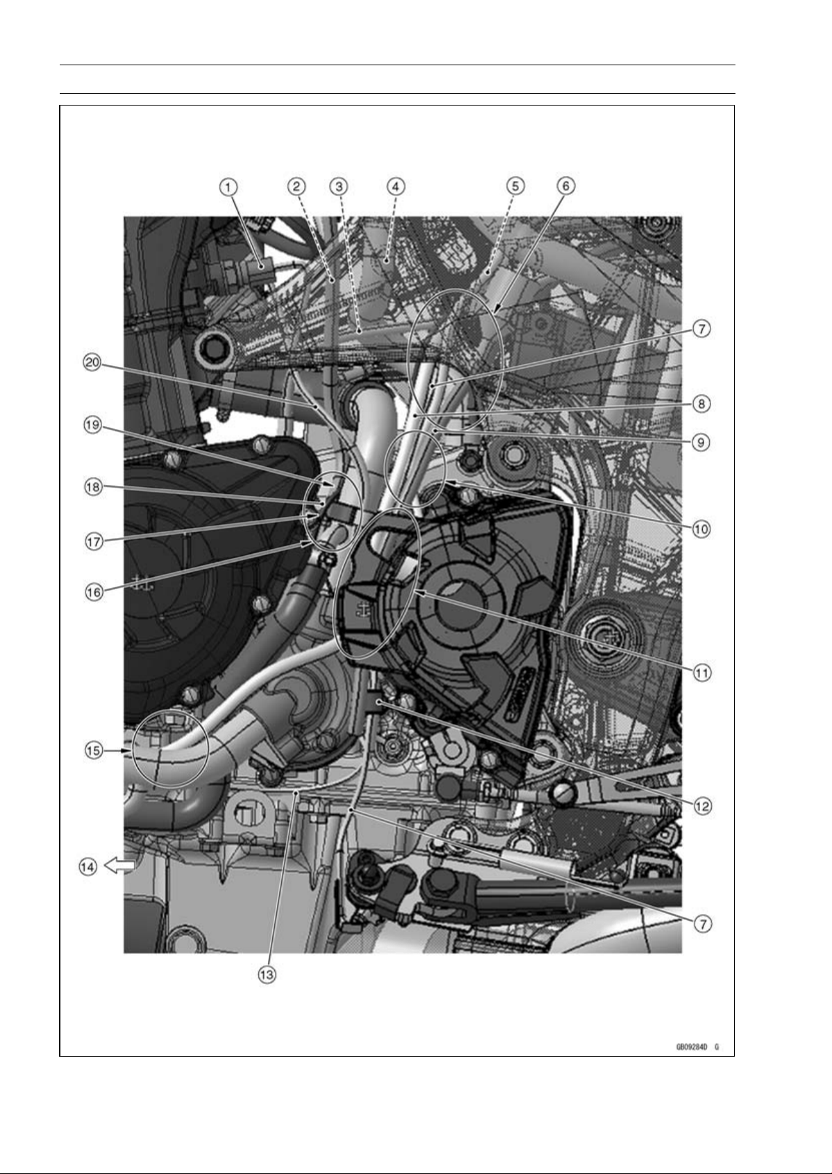
17-20 APPENDIX
Cable, Wire, and Hose Routing

APPENDIX 17-21
Cable, Wire, and Hose Routing
1. Water Temperature Sensor Lead Connector
2. Air Cleaner Drain Hose
3. Starter Motor Cable
4. Breather Hose
5. Speed Sensor Lead
6. Run the speed sensor lead and sidestand switch lead to the outside of the starter motor cable
and to the front side of the fuel tank breather hose (other than CAL, SEA-B1 and TH models).
7. Sidestand Switch Lead
8. Fuel Tank Drain Hose
9. Fuel Tank Breather Hose (Other than CAL, SEA-B1 and TH Models)
10. Run the speed sensor lead and sidestand switch lead to the inside of the fuel tank breather hose
(other than CAL, SEA-B1 and TH models) and fuel tank drain hose.
11. Run the fuel tank breather hose (other than CAL, SEA-B1 and TH models) and fuel tank drain
hose to the inside of the chain cover.
12. Hold the sidestand switch lead and taping portion of the neutral switch/oil pressure switch lead
with the clamp. Touch the clamp to the boss of the water pump cover.
13. Oil Pressure Switch Lead
14. Front
15. Run the fuel tank drain hose to the inside of the water pipe.
16. Run the air cleaner drain hose between the water pipe and alternator cover.
17. Run the alternator lead to the inside of the neutral switch/oil pressure switch lead.
18. Alternator Lead
19. Run the air cleaner drain hose to the inside of the neutral switch/oil pressure switch lead and
alternator lead.
20. Neutral Switch/Oil Pressure Switch Lead
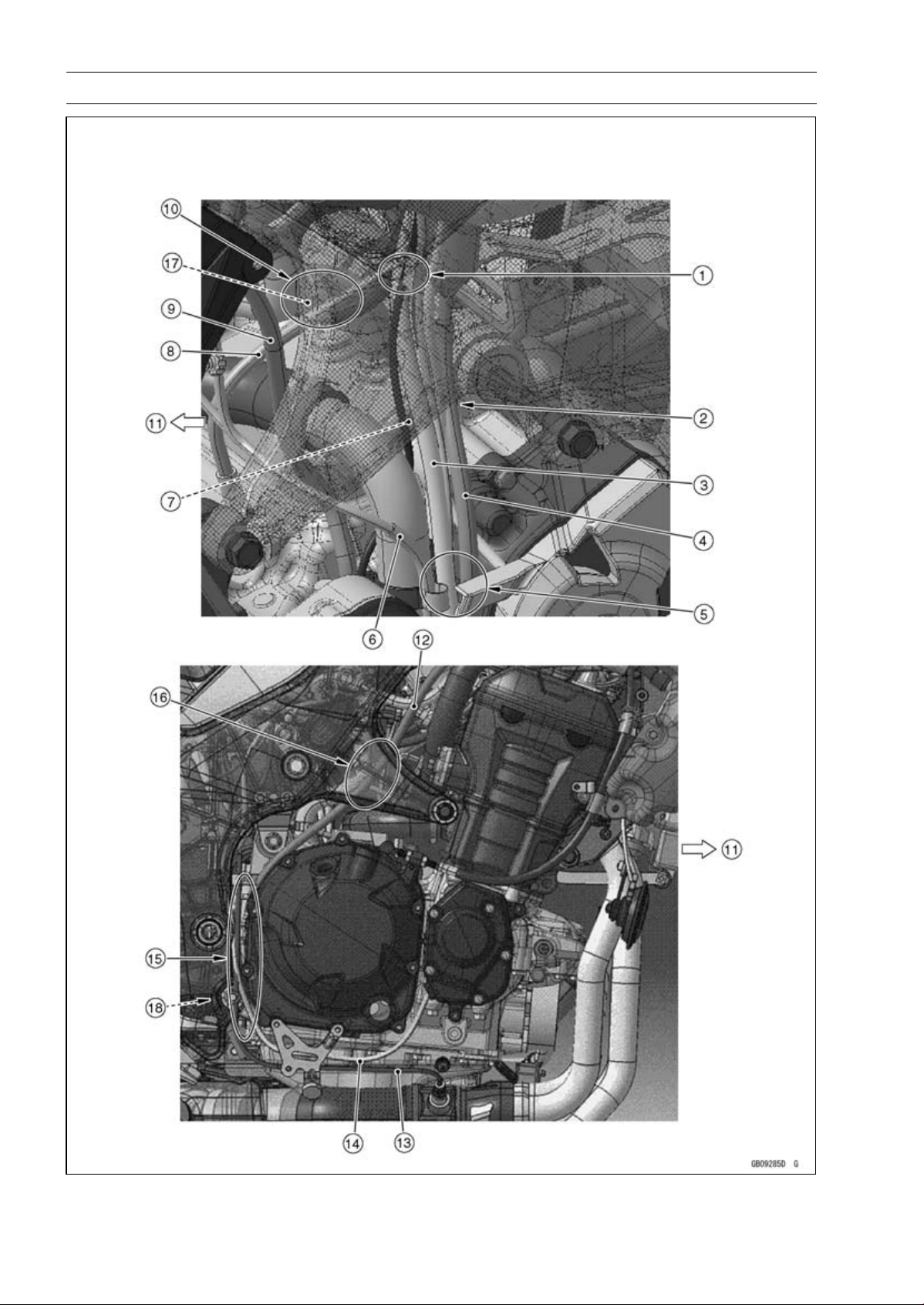
17-22 APPENDIX
Cable, Wire, and Hose Routing

APPENDIX 17-23
Cable, Wire, and Hose Routing
1. Run the fuel hose, starter motor cable, and alternator lead in order from the inside of the frame.
2. Run the fuel tank breather hose (other than CAL, SEA-B1 and TH models) and fuel tank drain
hose to the outside of the sidestand lead and speed sensor lead.
3. Fuel Tank Drain Hose
4. Fuel Tank Breather Hose (other than CAL, SEA-B1 and TH Models)
5. Run the fuel tank breather hose (other than CAL, SEA-B1 and TH models) and fuel tank drain
hose to the inside of the chain cover.
6. Neutral Switch/Oil Pressure Switch Lead
7. Alternator Lead
8. Starter Motor Cable
9. Air Cleaner Drain Hose
10. Run the fuel hose to the upside of the water hose.
11. Front
12. Reserve Tank Overflow Hose
13. Oxygen Sensor Lead (Equipped Models)
14. Crankshaft Sensor Lead
15. Run the reserve tank overflow hose to the inside of the oxygen sensor lead (equipped models)
and crankshaft sensor lead.
16. Run the reserve tank overflow hose to the inside of the frame.
17. Fuel Hose
18. Run the reserve tank overflow hose to the rear side of the lower adjusting collar and between
the lower adjusting collar and frame.
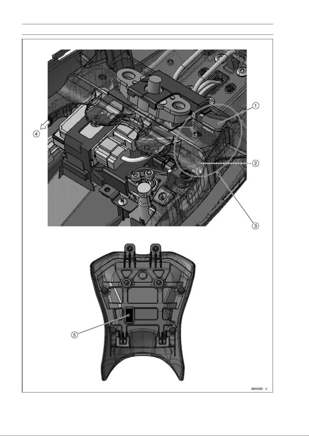
17-24 APPENDIX
Cable, Wire, and Hose Routing

APPENDIX 17-25
Cable, Wire, and Hose Routing
1. Turn Signal Relay
2. Seat Lock Cable
3. Run the seat lock cable to the outside of the turn signal relay and to the upside of the other
leads.
4. Front
5. Stick the damper to the lower side of the front seat as shown.
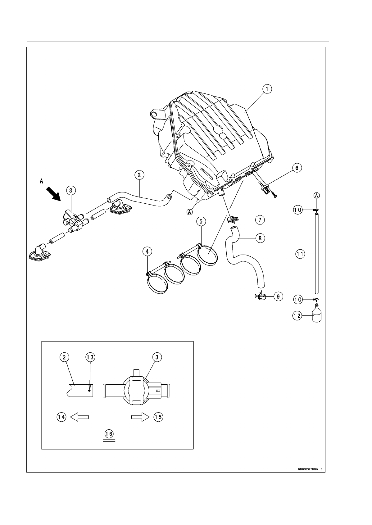
17-26 APPENDIX
Cable, Wire, and Hose Routing

APPENDIX 17-27
Cable, Wire, and Hose Routing
1. Air Cleaner Housing
2. Air Switching Valve Hose
3. Air Switching Valve
4. Tighten the clamp bolt from left side.
5. Tighten the clamp bolt from right side.
6. Intake Air Temperature Sensor
7. Install the clamp so that knob of the clamp faces rear side of the frame as shown.
8. Breather Hose
9. Clamp
10. Clamps
11. Air Cleaner Drain Hose
12. Catch Tank
13. White Paint Mark
14. Right Side of the Frame
15. Left Side of the Frame
16. Viewed from A
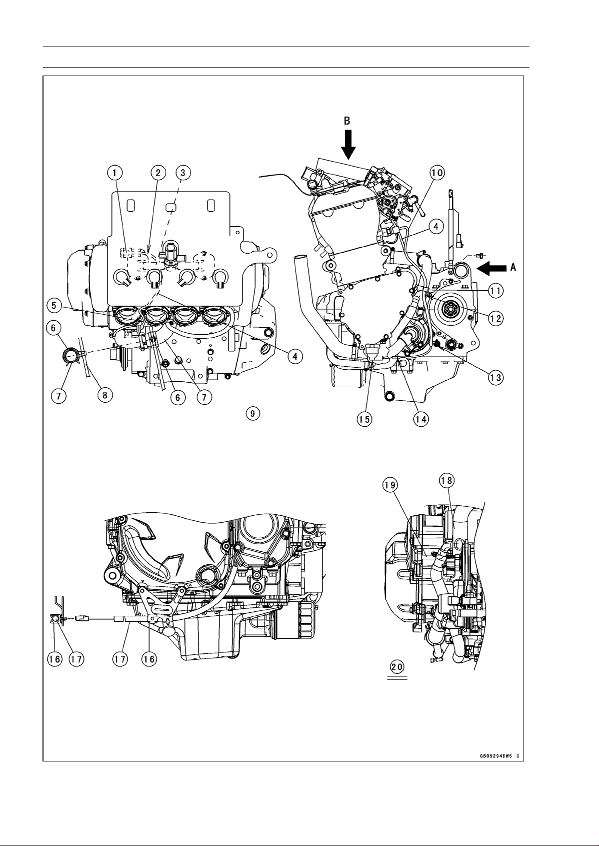
17-28 APPENDIX
Cable, Wire, and Hose Routing

APPENDIX 17-29
Cable, Wire, and Hose Routing
1. Insert the subharness connector to the clamp on the air suction valve cover.
2. Run the subharness under the hose.
3. Hose
4. Subharness
5. Run the subharness between the #1 and #2 throttle body holders so as not to pinch the lead
with the throttle body assy.
6. Install the clamp as shown in the direction.
7. Water Hose
8. Starter Motor Cable
9. Viewed from B
10. Water Temperature Sensor Lead
11. Hold the neutral switch/oil pressure switch lead with the clamp at the upside of the separate
pipe of the water pipe.
12. Run the neutral switch/oil pressure switch lead with the clamp at the rear side of the separate
pipe of the water pipe.
13. Connect the neutral switch lead to the neutral switch. Do not stretch the lead after connected.
14. Run the oil pressure switch lead to the inside of the water pipe.
15. Cover the oil pressure switch with the switch cover.
16. Hold the crankshaft sensor lead with the clamp.
17. Crankshaft Sensor Lead
18. Water pipe
19. Run the alternator lead between the crankcase and water pipe.
20. Viewed from A
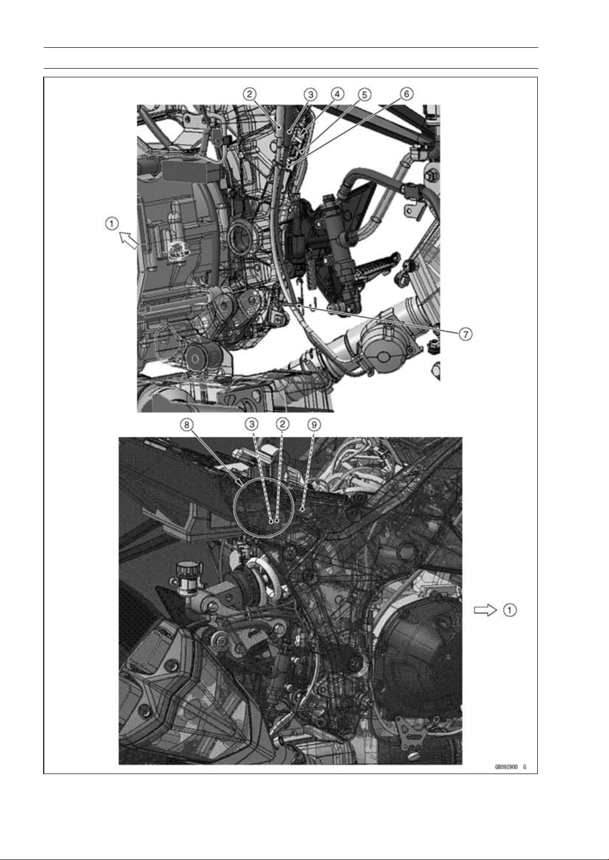
17-30 APPENDIX
Cable, Wire, and Hose Routing

APPENDIX 17-31
Cable, Wire, and Hose Routing
1. Front
2. Exhaust Butterfly Valve Open Cable (White)
3. Exhaust Butterfly Valve Close Cable (Black)
4. Run the exhaust butterfly valve cables to the inside of the rear brake light switch lead.
5. Rear Brake Light Switch Lead
6. Run the exhaust butterfly valve open cable and close cable through the clamp in order from the
front.
7. Run the exhaust butterfly valve open cable and close cable through the clamp in order from the
front.
8. Run the exhaust butterfly valve cables to the inside of the main harness.
9. Main Harness
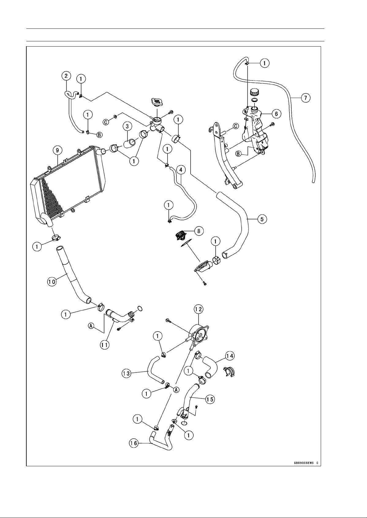
17-32 APPENDIX
Cable, Wire, and Hose Routing

APPENDIX 17-33
Cable, Wire, and Hose Routing
1. Install the clamps as shown in the direction.
2. Reserve Tank Hose
3. Radiator Hose
4. Water Hose
5. Water Hose
6. Reserve Tank
7. Reserve Tank Overflow Hose
8. Thermostat
9. Radiator
10. Radiator Hose
11. Water Pipe
12. Oil Cooler
13. Water Hose
14. Water Hose
15. Water Pipe
16. Water Hose
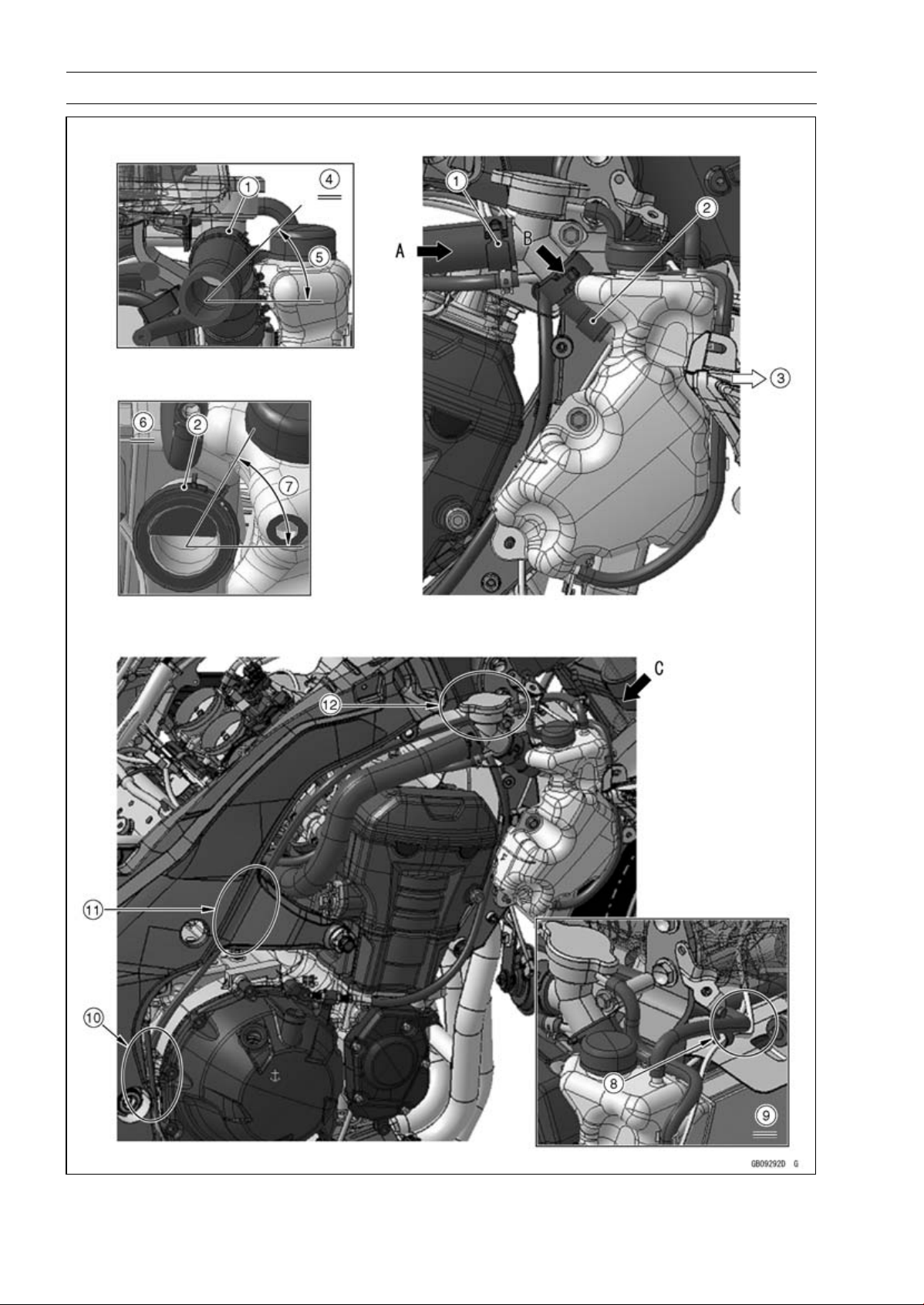
17-34 APPENDIX
Cable, Wire, and Hose Routing

APPENDIX 17-35
Cable, Wire, and Hose Routing
1. Install the clamp as shown in the direction.
2. Install the clamp as shown in the direction.
3. Front
4. Viewed From A
5. About 45°
6. Viewed From B
7. About 60°
8. Run the reserve tank overflow hose to the upside of the horn lead and front right turn signal light
lead.
9. Viewed From C
10. Run the reserve tank overflow hose to the rear side of the crankcase.
11. Run the reserve tank overflow hose to the inside of the frame.
12. Run the reserve tank overflow hose to the inside of the upper engine bracket.
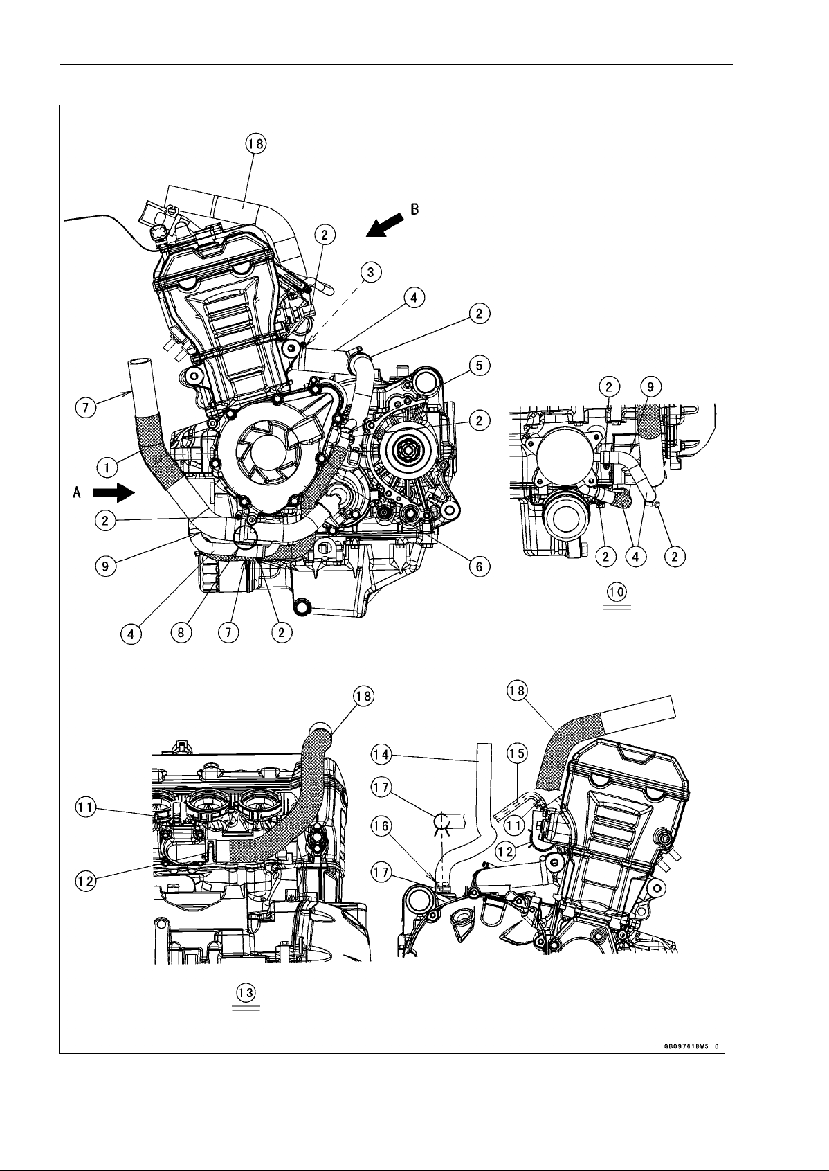
17-36 APPENDIX
Cable, Wire, and Hose Routing

APPENDIX 17-37
Cable, Wire, and Hose Routing
1. Radiator Hose
2. Install the clamps as shown in the direction.
3. White Paint Mark (Install the water hose so that the white paint mark faces upside of the engine.)
4. Water Hose
5. White Paint Mark (Install the water hose so that the white paint mark faces outside of the engine.)
6. Water Hose
7. Straight Side
8. Install the radiator hose until the rised portion of the water pipe.
9. Curve Side
10. Viewed from A
11. Install the clamp so that the tab of the clamp faces rear side of the engine.
12. Install the clamp at the thermostat housing as shown in the figure so that the tab of the clamp
faces rear side of the engine.
13. Viewed from B
14. Breather Hose
15. Water Hose
16. White Paint Mark
17. Install the clamp so that the tab of the clamp faces right side of the engine.
18. Water Hose
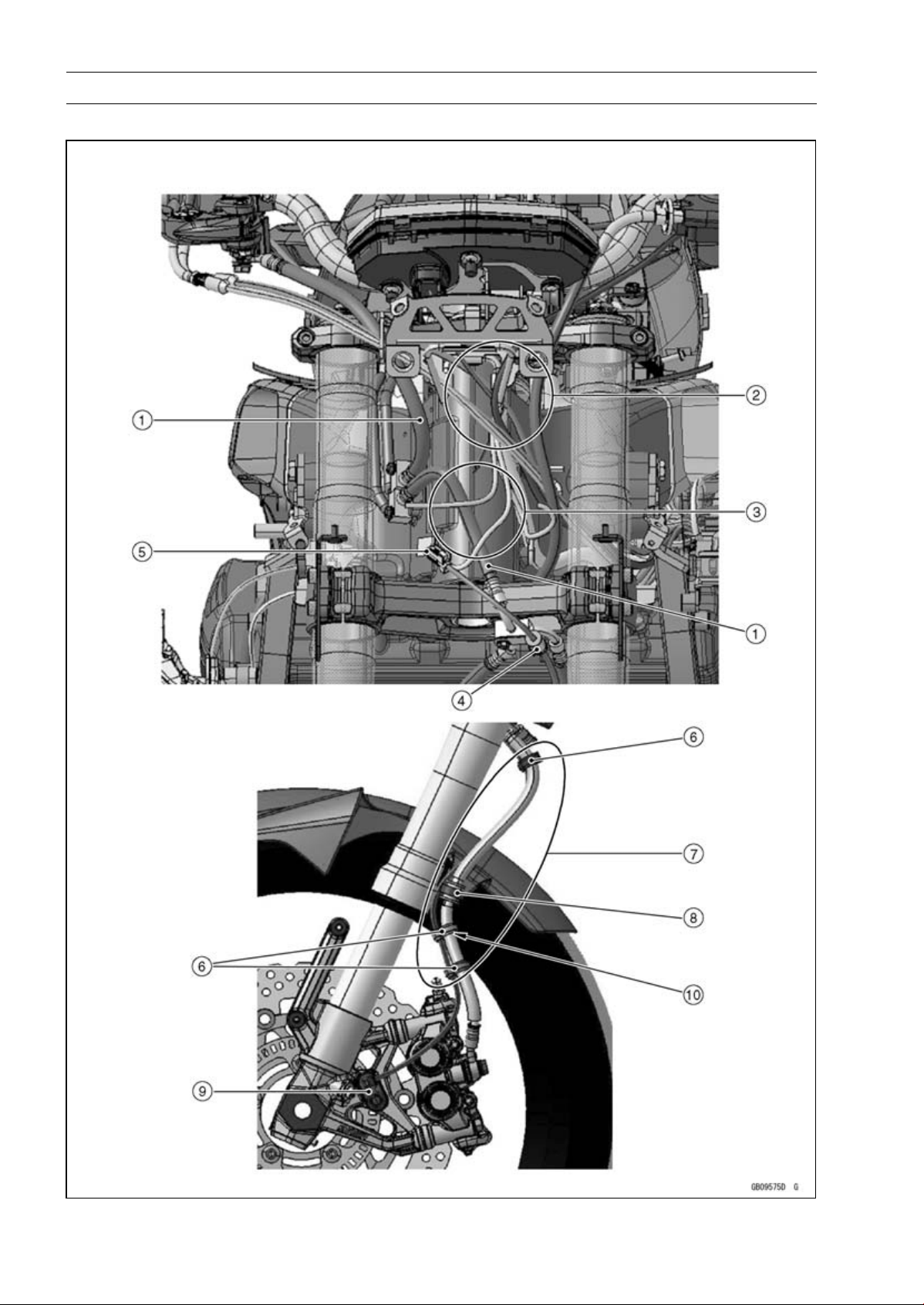
17-38 APPENDIX
Cable, Wire, and Hose Routing
ABS Equipped Models (ZR1000EA)

APPENDIX 17-39
Cable, Wire, and Hose Routing
1. Brake Hoses
2. Run the left and right switch housing leads into the upper fairing bracket.
3. Run the brake hose to the rear side of the headlight harness.
4. Clamp (Clamp the grommet on the front wheel rotation sensor lead.)
5. Front Wheel Rotation Sensor Connector
6. Clamps (for Brake Hose and Front Rotation Sensor Lead)
7. Run the front wheel rotation sensor lead to the inside of the brake hose.
8. Clamp the grommet on the brake hose (Run the front wheel rotation sensor to the outside of the
clamp.).
9. Front Wheel Rotation Sensor
10. White paint Mark
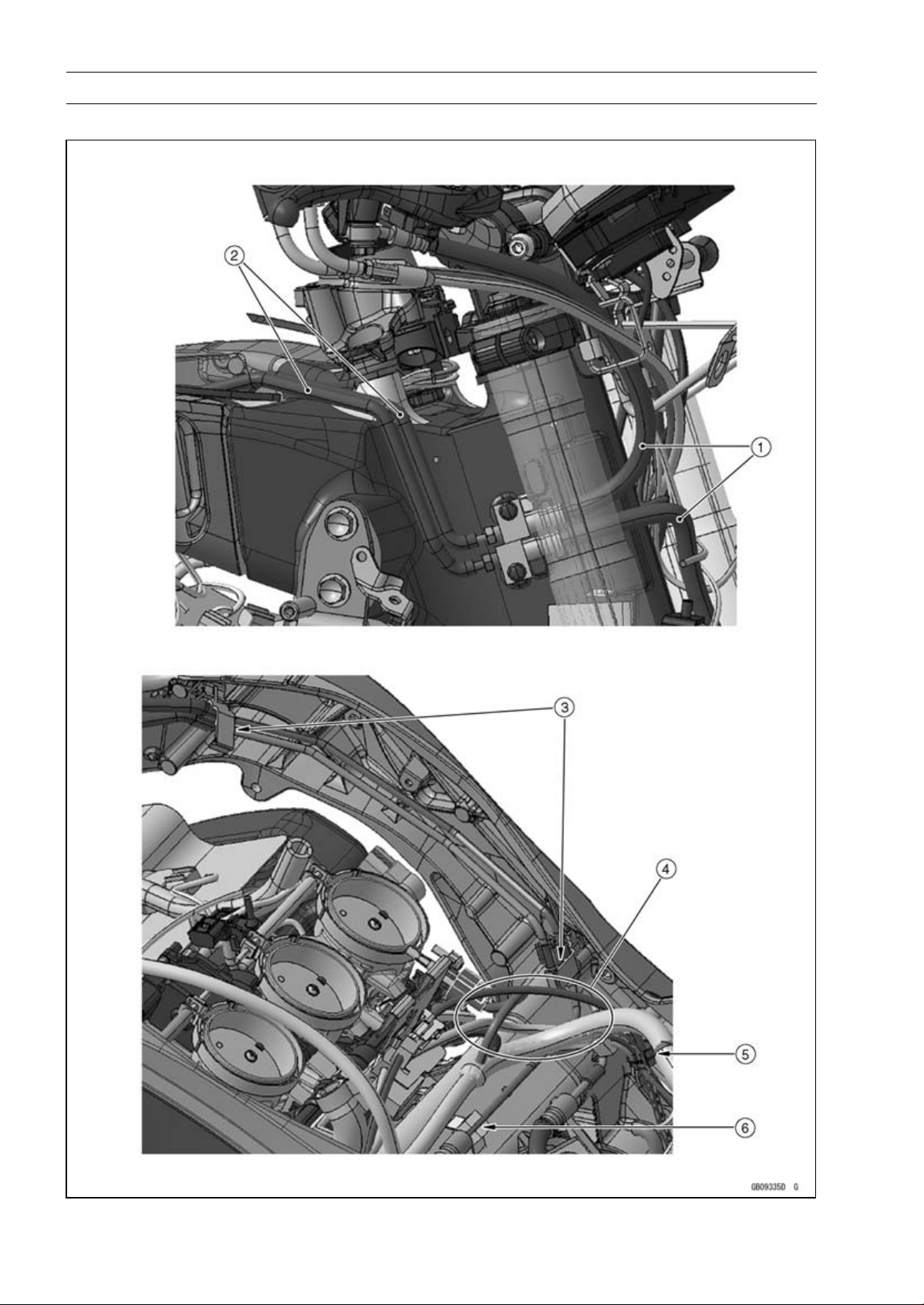
17-40 APPENDIX
Cable, Wire, and Hose Routing
ABS Equipped Models

APPENDIX 17-41
Cable, Wire, and Hose Routing
1. Brake Hoses
2. Brake Hoses (Brake Pipes)
3. Hold the brake pipes at the rubber portions with the clamps.
4. Run the brake pipes under the harnesses.
Run the rear wheel rotation sensor lead to the outside of the main harness and upper the intake
air temperature sensor lead.
5. Clamp (for Rear Brake Light Switch Lead, Crankshaft Sensor Lead, Oxygen Sensor Lead and
Rear Wheel Rotation Sensor Lead)
6. Clamp (for Brake Pipe)
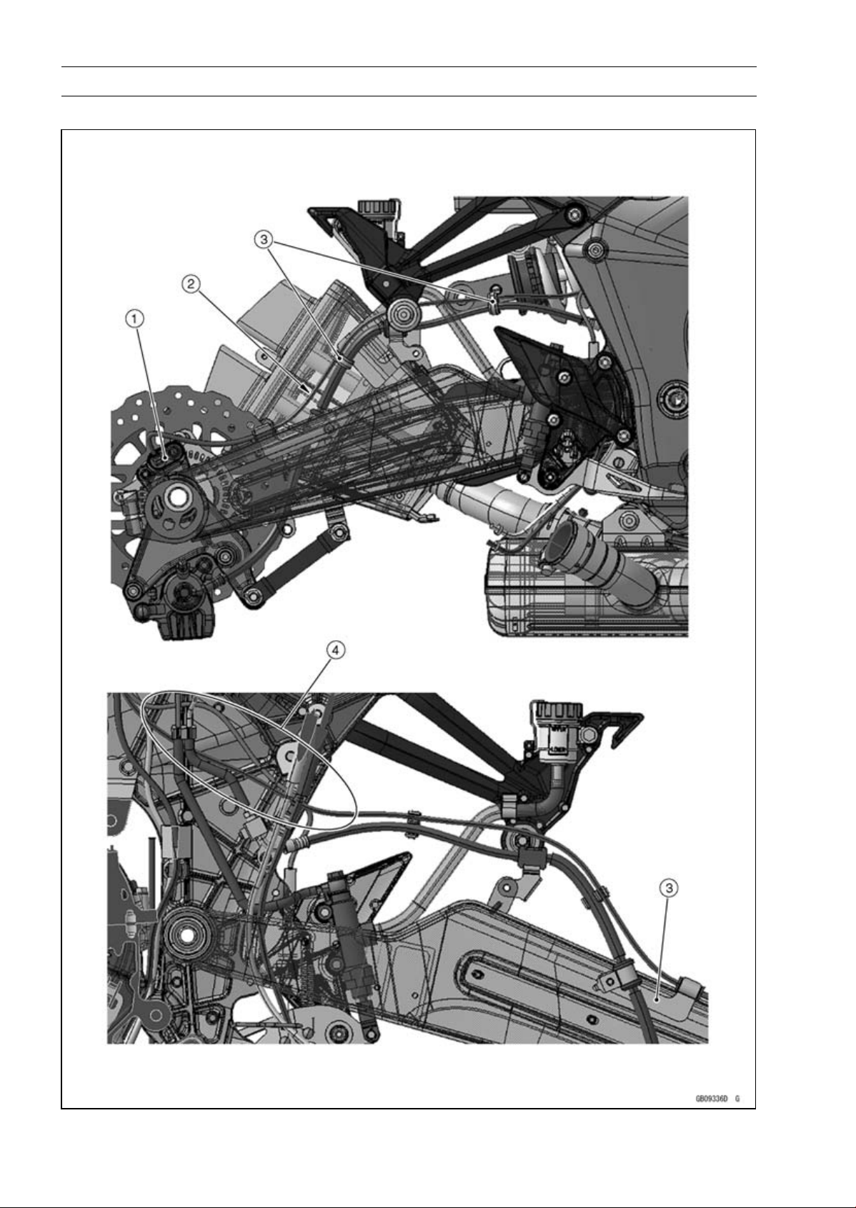
17-42 APPENDIX
Cable, Wire, and Hose Routing
ABS Equipped Models

APPENDIX 17-43
Cable, Wire, and Hose Routing
1. Rear Wheel Rotation Sensor
2. Run the rear wheel rotation sensor lead upper the brake hose.
3. Clamp (for Brake Hose and Rear Wheel Rotation Sensor Lead)
4. Run the rear brake light switch lead and rear wheel rotation sensor lead to the outside of the
exhaust butterfly valve cables and brake pipe.
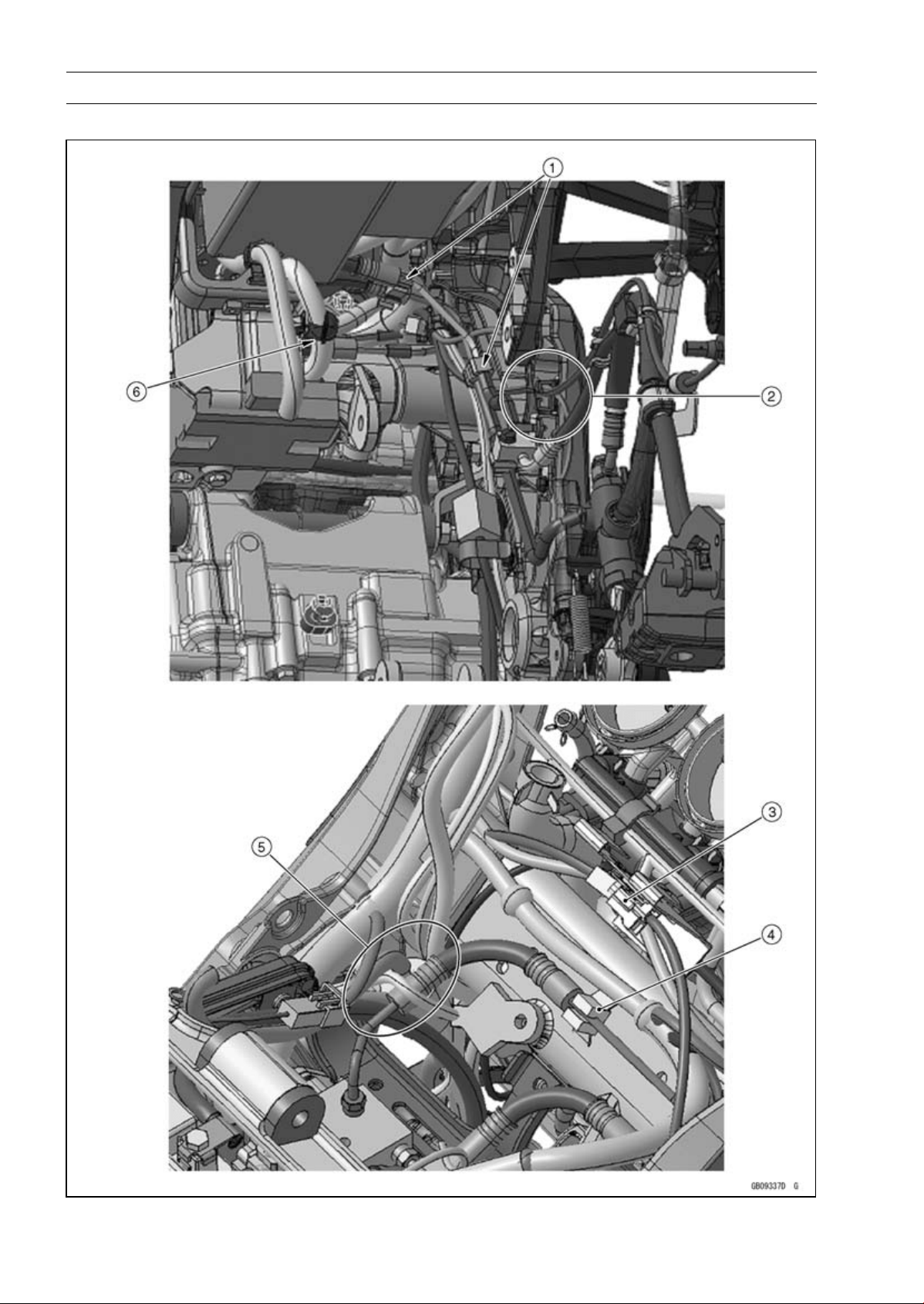
17-44 APPENDIX
Cable, Wire, and Hose Routing
ABS Equipped Models

APPENDIX 17-45
Cable, Wire, and Hose Routing
1. Clamp (for Brake Pipes)
2. Clamp (for Rear Brake Light Switch Lead and Rear Wheel Rotation Sensor Lead)
3. Rear Wheel Rotation Sensor Connector
4. Clamp (for Brake Pipe)
5. Run the brake hose inside of the harnesses and under the frame ground lead.
6. Run the ABS hydraulic unit harness under the battery case so that the harness has no play in
this position (Pull up the ABS hydraulic unit harness at the front side of the battery case.).
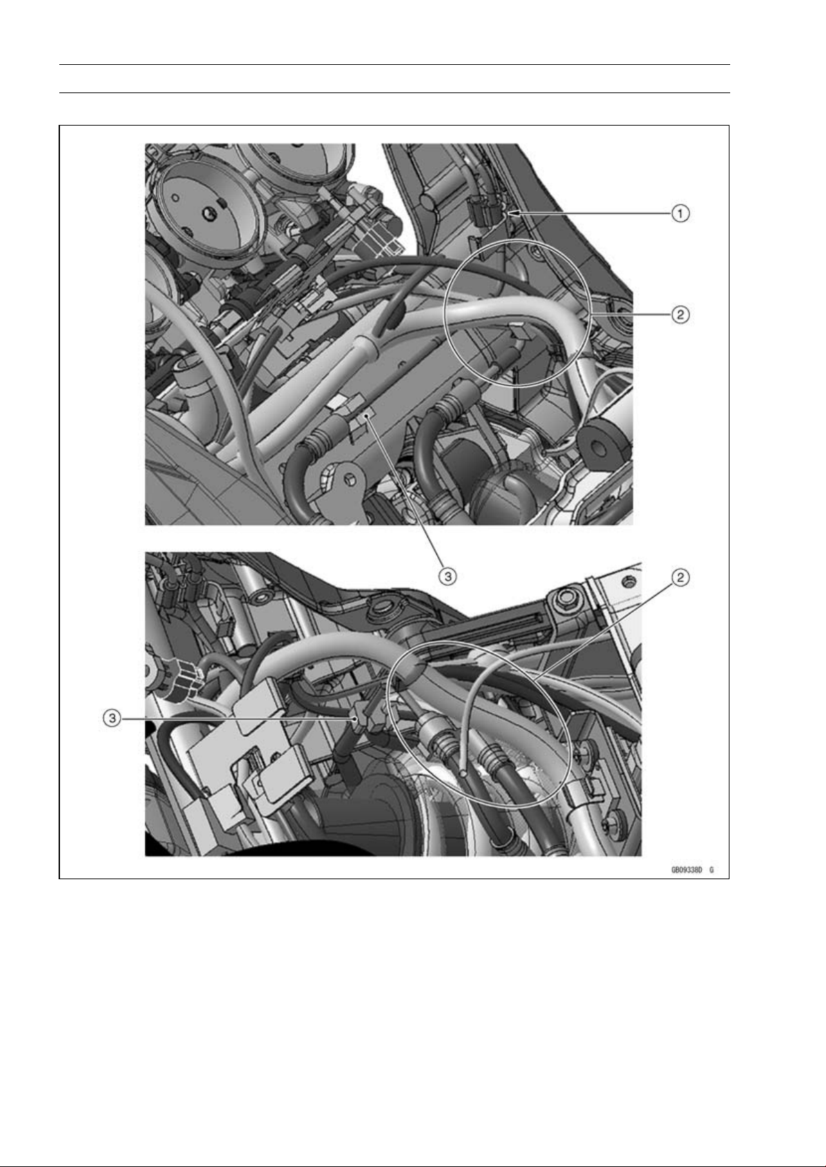
17-46 APPENDIX
Cable, Wire, and Hose Routing
ABS Equipped Models
1. Hold the brake pipes at the rubber portions with the clamp.
2. Run the brake hoses under the harnesses.
3. Clamp (for Brake Pipes)
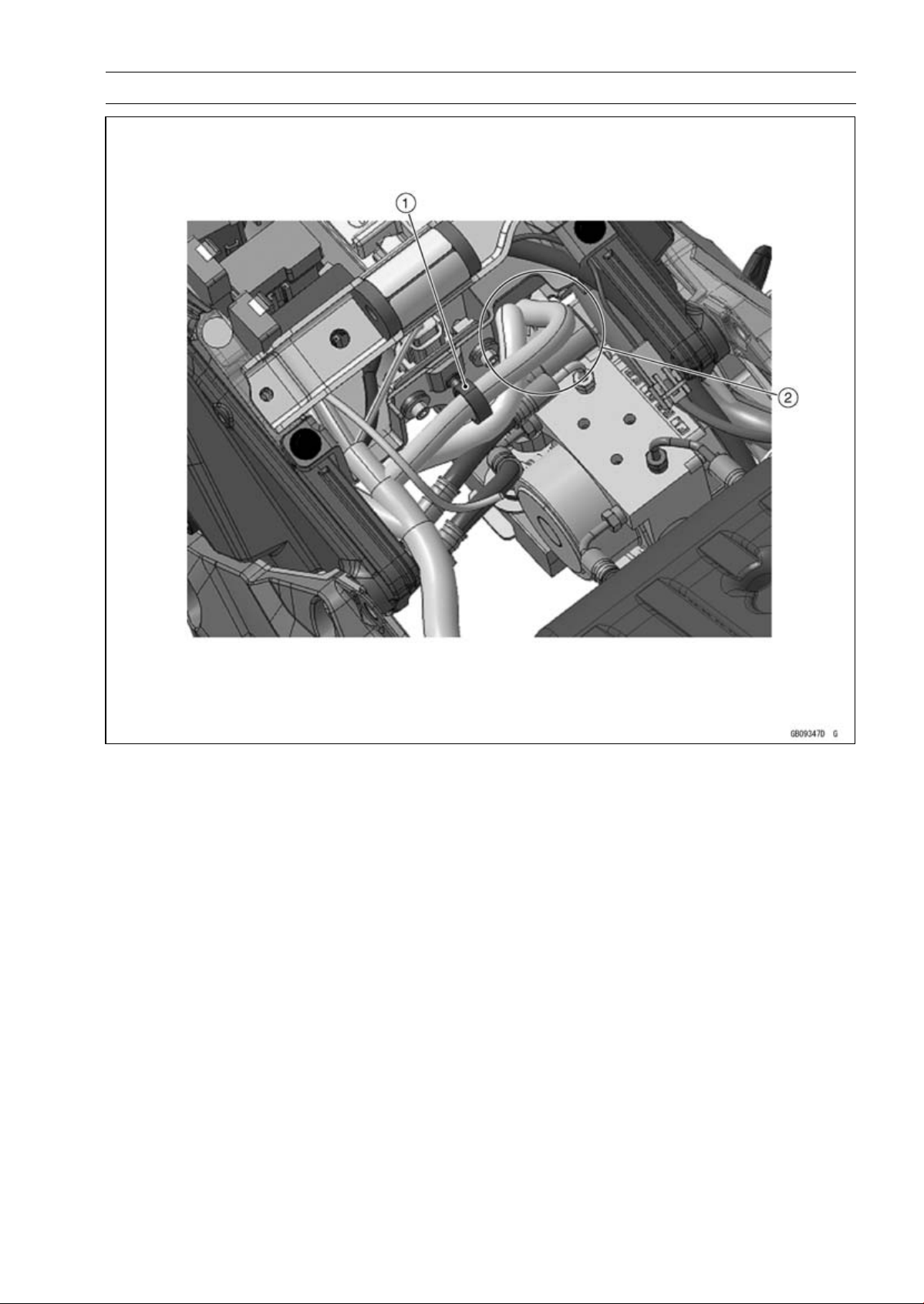
APPENDIX 17-47
Cable, Wire, and Hose Routing
1. Clamp (Hold the regulator/rectifier harness.)
2. Run the regulator/rectifier harness to the hollow on the battery case.
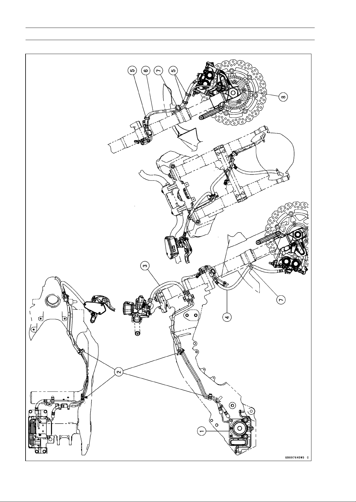
17-48 APPENDIX
Cable, Wire, and Hose Routing
ABS Equipped Models

APPENDIX 17-49
Cable, Wire, and Hose Routing
1. ABS Hydraulic Unit
2. Clamps
3. Brake Hose (between Front Master Cylinder and ABS Hydraulic Unit)
4. Brake Hose (between ABS Hydraulic Unit and Right Front Caliper)
5. Hold the front brake hose and the front wheel rotation sensor lead with the clamp at the white
painted portion of the sensor lead.
6. Brake Hose (between ABS Hydraulic Unit and Left Front Caliper)
7. Clamp (Hold the grommet of the brake hose only. For ZR1000EC ∼, face the lock of the clamp
backward.)
8. Front Wheel Rotation Sensor
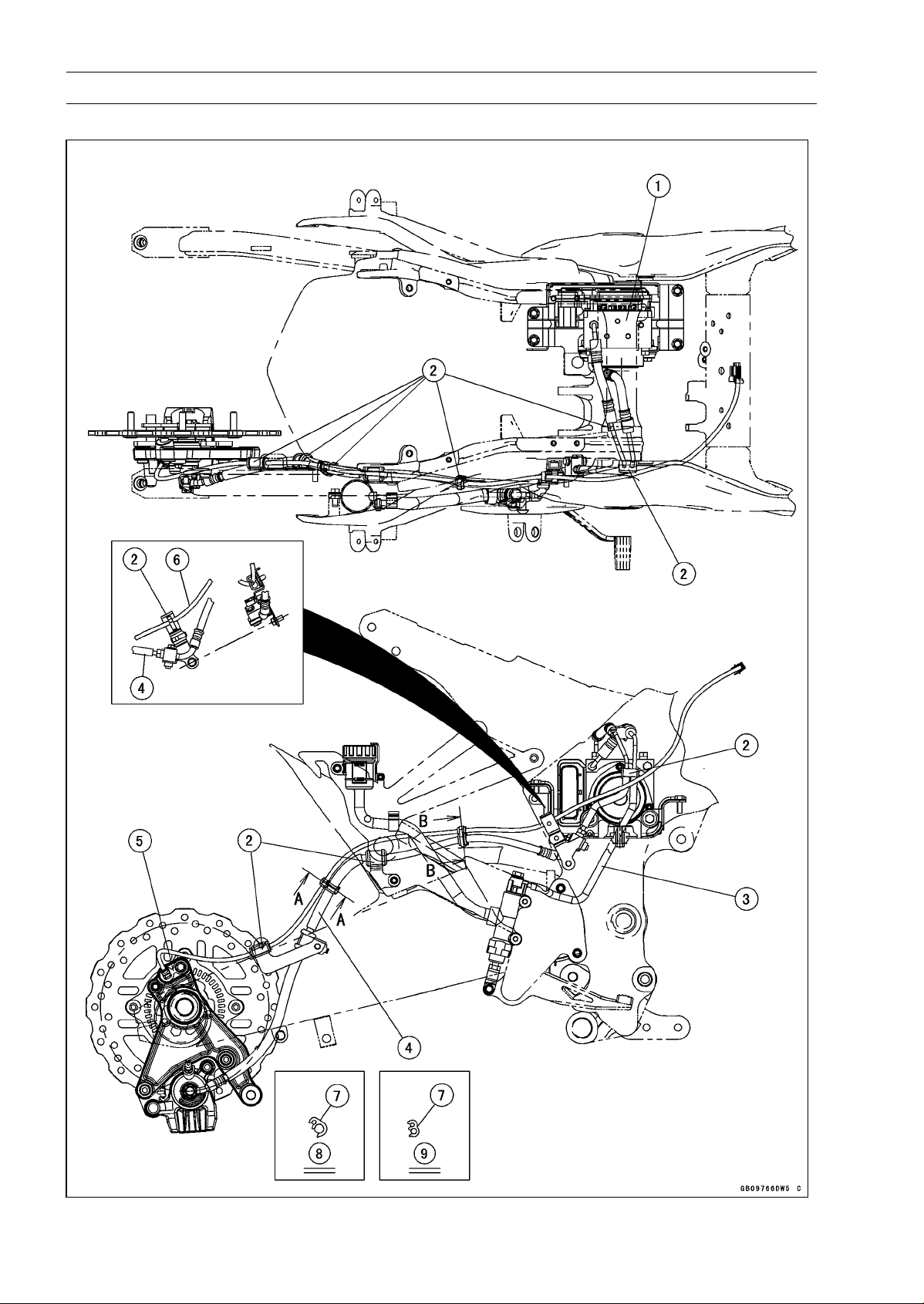
17-50 APPENDIX
Cable, Wire, and Hose Routing
ABS Equipped Models

APPENDIX 17-51
Cable, Wire, and Hose Routing
1. ABS Hydraulic Unit
2. Clamps
3. Brake Hose (between Rear Master Cylinder and ABS Hydraulic Unit)
4. Brake Hose (between ABS Hydraulic Unit and Rear Caliper)
5. Rear Wheel Rotation Sensor
6. Rear Wheel Rotation Sensor Lead
7. Clamp (Hold the rear wheel rotation sensor lead and the brake hose at the white painted portion.
Install the clamp to the right side.)
8. Section A-A
9. Section B-B
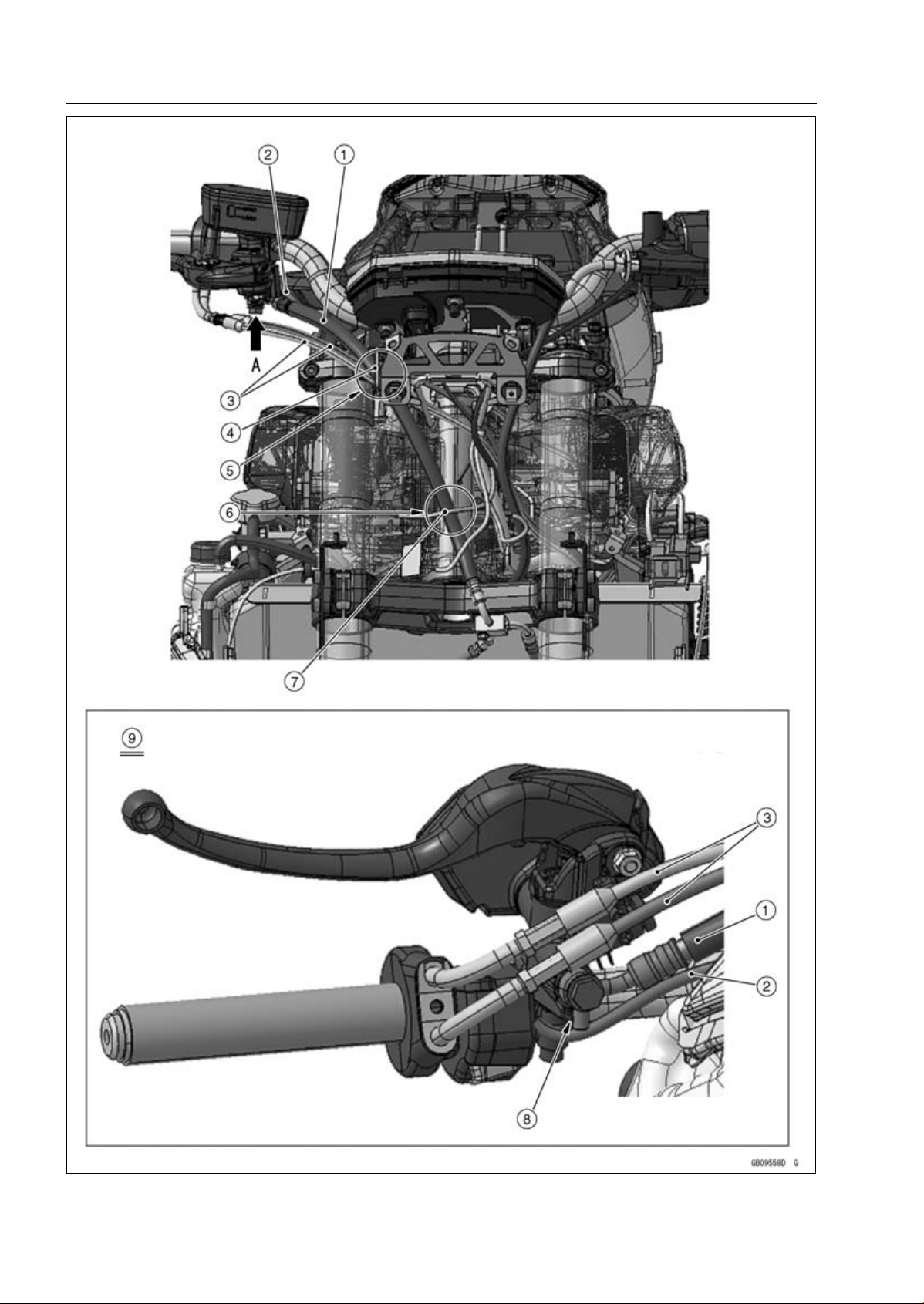
17-52 APPENDIX
Cable, Wire, and Hose Routing

APPENDIX 17-53
Cable, Wire, and Hose Routing
1. Brake Hose
2. Right Switch Housing Lead
3. Throttle Cables
4. Clamp of the upper fairing bracket.
5. Run the brake hose to the most outside of the other leads and cables, and through it to the
clamp.
6. Run the brake hose to the rear side of the headlight lead.
7. Headlight Lead
8. Fit the projection of the brake hose end to the stopper as shown, and tighten the brake hose
banjo bolt to the specified torque.
9. Viewed From A
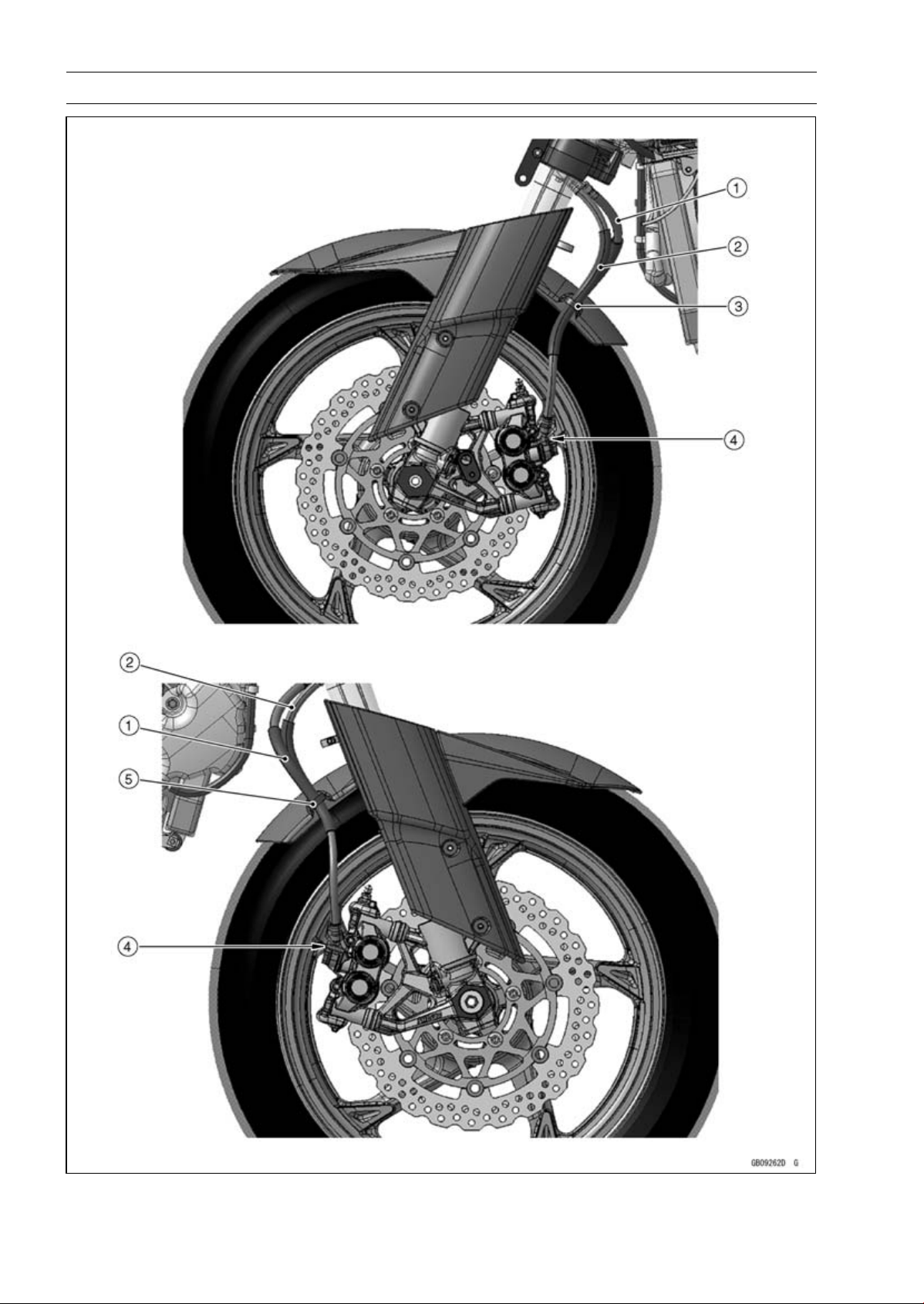
17-54 APPENDIX
Cable, Wire, and Hose Routing

APPENDIX 17-55
Cable, Wire, and Hose Routing
1. Brake Hose
2. Brake Hose
3. (ZR1000DA ∼ DB) Hold the brake hose with the clamp, and insert it to the front fender.
(ZR1000DC ∼) Hold the brake hose with the clamp at the grommet of the brake hose. Face the
lock of the clamp backward.
4. Fit the brake pipe to the stopper of the caliper as shown, and tighten the brake hose banjo bolt
to the specified torque.
5. (ZR1000DA ∼ DB) Hold the brake hose with the clamp, and insert it to the front fender.
(ZR1000DC ∼) Hold the brake hose with the clamp at the grommet of the brake hose. Face the
lock of the clamp backward.
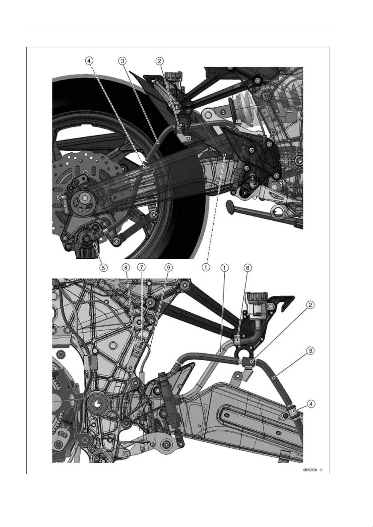
17-56 APPENDIX
Cable, Wire, and Hose Routing

APPENDIX 17-57
Cable, Wire, and Hose Routing
1. Brake Hose
2. Clamp
3. Brake Hose
4. Clamp
5. Fit the brake pipe to the stopper of the caliper as shown, and tighten the brake hose banjo bolt
to the specified torque.
6. Hold the brake hose with the clamp.
7. Hold the rear brake light switch lead with the clamp.
8. Clamp
9. Rear Brake Light Switch Lead
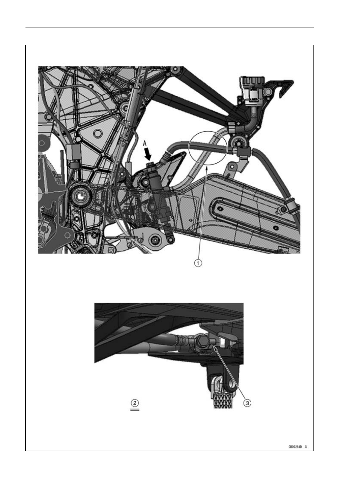
17-58 APPENDIX
Cable, Wire, and Hose Routing

APPENDIX 17-59
Cable, Wire, and Hose Routing
1. Run the brake hose (between rear master cylinder and rear caliper) to the inside of the brake
hose (from rear brake reserve tank to rear master cylinder).
2. Viewed From A
3. Fit the projection of the brake hose end to the stopper as shown, and tighten the brake hose
banjo bolt to the specified torque.
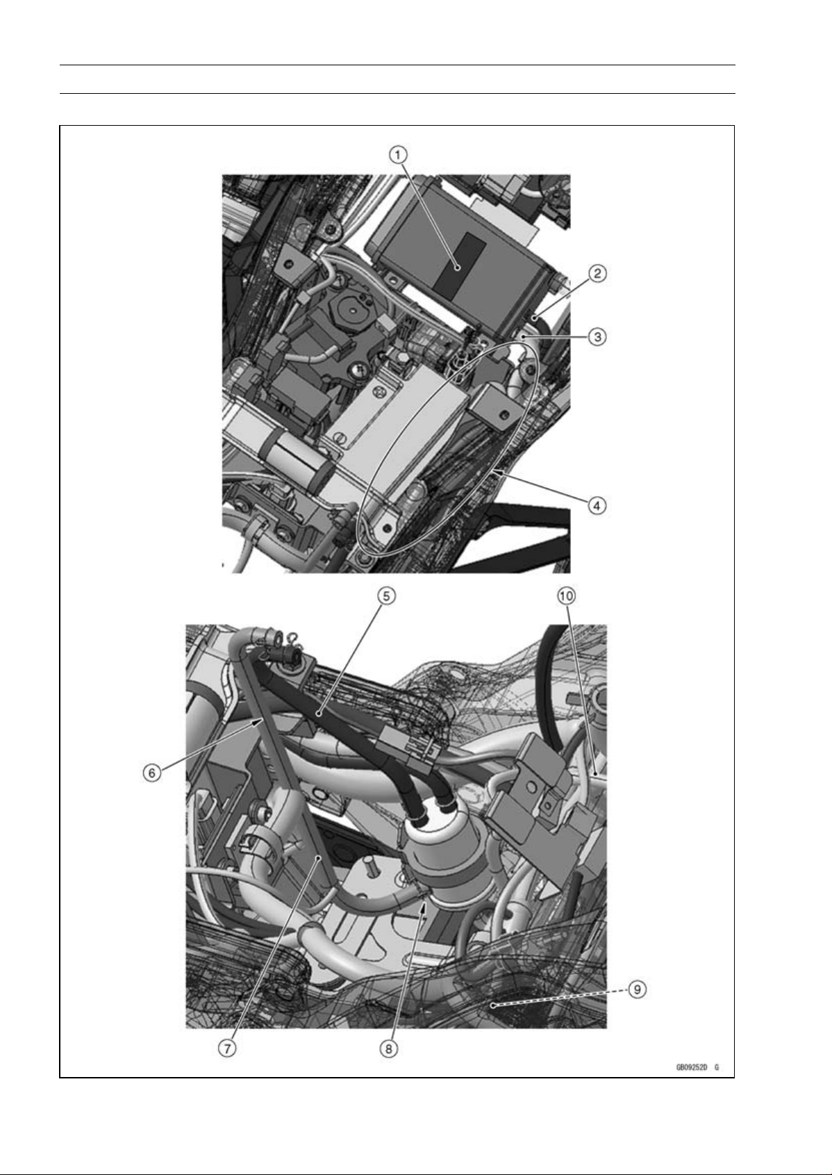
17-60 APPENDIX
Cable, Wire, and Hose Routing
CAL, SEA-B1 and TH Models

APPENDIX 17-61
Cable, Wire, and Hose Routing
1. Stick the damper on the front center of the canister as shown in the direction.
2. Blue Hose (between Separator and Canister)
3. Green Hose (between Canister and Fitting for Air Switching Valve)
4. Run the blue hose and green hose to the upside of the main harness and to the outside of the
starter motor cable.
5. Blue Hose (between Separator and Fuel Tank)
6. Run the blue hose and red hose to the inside of the battery negative (–) lead.
7. Red Hose (between Separator and Fuel Tank)
8. Install the separator so that the red hose fitting faces rearward and position the fitting to right
side about 45°.
9. Run the green hose to the upside of the other leads.
10. White Hose (between Separator and Throttle Body #2)

17-62 APPENDIX
Cable, Wire, and Hose Routing
CAL, SEA-B1 and TH Models

APPENDIX 17-63
Cable, Wire, and Hose Routing
1. Run the green hose to the inside of the sidestand switch lead and speed sensor lead, under the
frame ground leads, and to the outside of the battery negative (–) lead.
2. Green Hose (between Canister and Fitting for Air Switching Valve)
3. Speed Sensor Lead
4. Sidestand Switch Lead
5. White Hose (between Separater and Throttle Body #2)
6. Front
7. Run the white hose under the delivery pipe of the throttle body assy, crankshaft sensor lead,
speed sensor lead, and frame ground leads. And run the white hose to the upside of the main
harness and green hose.
8. Crankshaft Sensor Lead
9. Main Harness
10. Hold the green hose with the clamps.
11. Frame Ground
12. Battery Negative (–) Cable
13. Reserve Tank Overflow Hose
14. Run the green hose under the reserve tank overflow hose and to the upside of the water hose.
15. Hold the reserve tank overflow hose and green hose with the clamp from outside of the frame.
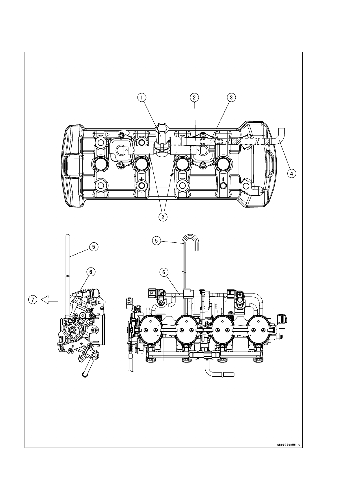
17-64 APPENDIX
Cable, Wire, and Hose Routing
CAL, SEA-B1 and TH Models

APPENDIX 17-65
Cable, Wire, and Hose Routing
1. Air Switching Valve
2. Hoses
3. Fitting
4. Install the green hose as shown in the direction.
5. Run the white hose to the front side of the vacuum hose.
6. Vacuum Hose
7. Front

17-66 APPENDIX
Troubleshooting Guide
NOTE
○
Refer to the Fuel System chapter for most
of DFI trouble shooting guide.
○
This is not an exhaustive list, giving every
possible cause for each problem listed. It
is meant simply as a rough guide to assist
the troubleshooting for some of the more
common difficulties.
Engine Doesn’t Start, Starting
Difficulty:
Starter motor not rotating:
Ignition and engine stop switch not ON
Starter lockout switch or neutral switch trou-
ble
Starter motor trouble
Battery voltage low
Starter relay not contacting or operating
Starter button not contacting
Starter system wiring shorted or open
Ignition switch trouble
Engine stop switch trouble
Main 30 A or ignition fuse blown
Starter motor rotating but engine doesn’t
turn over:
Vehicle-down sensor (DFI) coming off
Immobilizer system trouble (Equipped Mod-
els)
Starter clutch trouble
Starter idle gear trouble
Engine won’t turn over:
Valve seizure
Valve lifter seizure
Cylinder, piston seizure
Crankshaft seizure
Connecting rod small end seizure
Connecting rod big end seizure
Transmission gear or bearing seizure
Camshaft seizure
Starter idle gear seizure
Balancer bearing seizure
No fuel flow:
No fuel in tank
Fuel pump trouble
Fuel tank air vent obstructed
Fuel filter clogged
Fuel line clogged
No spark; spark weak:
Vehicle-down sensor (DFI) coming off
Ignition switch not ON
Engine stop switch turned OFF
Clutch lever not pulled in or gear not in neu-
tral
Battery voltage low
Immobilizer system trouble (Equipped Mod-
els)
Spark plug dirty, broken, or gap malad-
justed
Spark plug incorrect
Stick coil shorted or not in good contact
Stick coil trouble
ECU trouble
Neutral, starter lockout, or sidestand switch
trouble
Crankshaft sensor trouble
Ignition switch or engine stop switch
shorted
Starter system wiring shorted or open
Main 30 A or ignition fuse blown
Fuel/air mixture incorrect:
Bypass screw and/or idle adjusting screw
maladjusted
Air passage clogged
Air cleaner clogged, poorly sealed, or miss-
ing
Leak from oil filler cap, crankcase breather
hose or air cleaner drain hose.
Compression Low:
Spark plug loose
Cylinder head not sufficiently tightened
down
Cylinder, piston worn
Piston ring bad (worn, weak, broken, or
sticking)
Piston ring/groove clearance excessive
Cylinder head gasket damaged
Cylinder head warped
Valvespringbrokenorweak
No valve clearance
Valve not seating properly (valve bent,
worn, or carbon accumulation on the
seating surface)
Poor Running at Low Speed:
Spark weak:
Battery voltage low
Immobilizer system trouble (Equipped Mod-
els)
Stick coil trouble
Stick coil shorted or not in good contact
Spark plug dirty, broken, or maladjusted
Spark plug incorrect
ECU trouble
Crankshaft sensor trouble
Fuel/air mixture incorrect:
Bypass screw maladjusted
Air passage clogged
Air bleed pipe bleed holes clogged
Pilot passage clogged
Air cleaner clogged, poorly sealed, or miss-
ing
Fuel tank air vent obstructed
Fuel pump trouble

APPENDIX 17-67
Troubleshooting Guide
Throttle body assy holder loose
Air cleaner duct loose
Compression low:
Spark plug loose
Cylinder head not sufficiently tightened
down
No valve clearance
Cylinder, piston worn
Piston ring bad (worn, weak, broken, or
sticking)
Piston ring/groove clearance excessive
Cylinder head gasket damaged
Cylinder head warped
Valve spring broken or weak
Valve not seating properly (valve bent,
worn, or carbon accumulation on the
seating surface)
Camshaft cam worm
Run-on (dieseling):
Ignition switch trouble
Engine stop switch trouble
Fuel injector trouble
Loosen terminal of battery (–) cable or ECU
ground lead
Carbon accumulating on valve seating sur-
face
Engine overheating
Other:
ECU trouble
Throttle body assy not synchronizing
Engine oil viscosity too high
Drive train trouble
Brake dragging
Clutch slipping
Engine overheating
Air suction valve trouble
Air switching valve trouble
Poor Running or No Power at High
Speed:
Firing incorrect:
Spark plug dirty, broken, or maladjusted
Spark plug incorrect
Stick coil shorted or not in good contact
trouble
Stick coil trouble
ECU trouble
Fuel/air mixture incorrect:
Air cleaner clogged, poorly sealed, or miss-
ing
Air cleaner duct loose
Water or foreign matter in fuel
Throttle body assy holder loose
Fuel to injector insufficient
Fuel tank air vent obstructed
Fuel line clogged
Fuel pump trouble
Compression low:
Spark plug loose
Cylinder head not sufficiently tightened
down
No valve clearance
Cylinder, piston worn
Piston ring bad (worn, weak, broken, or
sticking)
Piston ring/groove clearance excessive
Cylinder head gasket damaged
Cylinder head warped
Valvespringbrokenorweak
Valve not seating properly (valve bent,
worn, or carbon accumulation on the
seating surface.)
Knocking:
Carbon built up in combustion chamber
Fuel poor quality or incorrect
Spark plug incorrect
ECU trouble
Miscellaneous:
Throttle valve won’t fully open
Brake dragging
Clutch slipping
Engine overheating
Engine oil level too high
Engine oil viscosity too high
Drive train trouble
Camshaft cam worm
Air suction valve trouble
Air switching valve trouble
Catalytic converter melt down due to muffler
overheating (KLEEN)
Overheating:
Firing incorrect:
Spark plug dirty, broken, or maladjusted
Spark plug incorrect
ECU trouble
Muffler overheating:
For KLEEN, do not run the engine even if
with only one cylinder misfiring or poor
running (Request the nearest service fa-
cility to correct it)
For KLEEN, do not push-start with a dead
battery (Connect another full-charged
battery with jumper cables, and start the
engine using the electric starter)
For KLEEN, do not start the engine under
misfire due to spark plug fouling or poor
connection of the stick coil
For KLEEN, do not coast the motorcycle
with the ignition switch off (Turn the igni-
tion switch ON and run the engine)
ECU trouble
Fuel/air mixture incorrect:
Throttle body assy holder loose

17-68 APPENDIX
Troubleshooting Guide
Air cleaner duct loose
Air cleaner poorly sealed, or missing
Air cleaner clogged
Compression high:
Carbon built up in combustion chamber
Engine load faulty:
Clutch slipping
Engine oil level too high
Engine oil viscosity too high
Drive train trouble
Brake dragging
Lubrication inadequate:
Engine oil level too low
Engine oil poor quality or incorrect
Oil cooler incorrect:
Oil cooler clogged
Gauge incorrect:
Water temperature gauge broken
Water temperature sensor broken
Coolant incorrect:
Coolant level too low
Coolant deteriorated
Wrong coolant mixed ratio
Cooling system component incorrect:
Radiator fin damaged
Radiator clogged
Thermostat trouble
Radiator cap trouble
Radiator fan relay trouble
Fan motor broken
Fan blade damaged
Water pump not turning
Water pump impeller damaged
Over Cooling:
Gauge incorrect:
Water temperature gauge broken
Water temperature sensor broken
Cooling system component incorrect:
Thermostat trouble
Clutch Operation Faulty:
Clutch slipping:
Friction plate worn or warped
Steel plate worn or warped
Clutch spring broken or weak
Clutch hub or housing unevenly worn
No clutch lever play
Clutch inner cable trouble
Clutch release mechanism trouble
Clutch not disengaging properly:
Clutch plate warped or too rough
Clutch spring compression uneven
Engine oil deteriorated
Engine oil viscosity too high
Engine oil level too high
Clutch housing frozen on drive shaft
Clutch hub nut loose
Clutch hub spline damaged
Clutch friction plate installed wrong
Clutch lever play excessive
Clutch release mechanism trouble
Gear Shifting Faulty:
Doesn’t go into gear; shift pedal doesn’t
return:
Clutch not disengaging
Shift fork bent or seized
Gear stuck on the shaft
Gear positioning lever binding
Shift return spring weak or broken
Shift return spring pin loose
Shift mechanism arm spring broken
Shift mechanism arm broken
Shift pawl broken
Jumps out of gear:
Shift fork ear worn, bent
Gear groove worn
Gear dogs and/or dog holes worn
Shift drum groove worn
Gear positioning lever spring weak or bro-
ken
Shift fork guide pin worn
Drive shaft, output shaft, and/or gear
splines worn
Overshifts:
Gear positioning lever spring weak or bro-
ken
Shift mechanism arm spring broken
Abnormal Engine Noise:
Knocking:
ECU trouble
Carbon built up in combustion chamber
Fuel poor quality or incorrect
Spark plug incorrect
Overheating
Piston slap:
Cylinder/piston clearance excessive
Cylinder, piston worn
Connecting rod bent
Piston pin, piston pin hole worn
Valve noise:
Valve clearance incorrect
Valvespringbrokenorweak
Camshaft bearing worn
Valve lifter worn
Other noise:
Connecting rod small end clearance exces-
sive
Connecting rod big end clearance exces-
sive
Piston ring/groove clearance excessive
Piston ring worn, broken, or stuck

APPENDIX 17-69
Troubleshooting Guide
Piston ring groove worn
Piston seizure, damage
Cylinder head gasket leaking
Exhaust pipe leaking at cylinder head con-
nection
Crankshaft runout excessive
Engine mount loose
Crankshaft bearing worn
Primary gear worn or chipped
Camshaft chain tensioner trouble
Camshaft chain, sprocket, guide worn
Air suction valve damaged
Air switching valve damaged
Alternator rotor loose
Catalytic converter melt down due to muffler
overheating (KLEEN)
Exhaust butterfly valve cable loose
Balancer gear worn or chipped
Balancer shaft position maladjusted
Balancer bearing worn
Balancer rubber damper damaged
Abnormal Drive Train Noise:
Clutch noise:
Clutch damper weak or damaged
Clutch housing/friction plate clearance ex-
cessive
Clutch housing gear worn
Wrong installation of outside friction plate
Transmission noise:
Bearings worn
Transmission gear worn or chipped
Metal chips jammed in gear teeth
Engine oil insufficient
Drive line noise:
Drive chain adjusted improperly
Drive chain worn
Rear and/or engine sprocket worn
Chain lubrication insufficient
Rear wheel misaligned
Abnormal Frame Noise:
Front fork noise:
Oil insufficient or too thin
Spring weak or broken
Rear shock absorber noise:
Shock absorber damaged
Disc brake noise:
Pad installed incorrectly
Pad surface glazed
Disc warped
Caliper trouble
Other noise:
Bracket, nut, bolt, etc. not properly
mounted or tightened
Oil Pressure Warning Light Goes On:
Engine oil pump damaged
Engine oil screen clogged
Engine oil filter clogged
Engine oil level too low
Engine oil viscosity too low
Camshaft bearing worn
Crankshaft bearing worn
Oil pressure switch damaged
Wiring faulty
Relief valve stuck open
O-ring at the oil passage in the crankcase
damaged
Exhaust Smokes Excessively:
White smoke:
Piston oil ring worn
Cylinder worn
Valve oil seal damaged
Valve guide worn
Engine oil level too high
Black smoke:
Air cleaner clogged
Brown smoke:
Air cleaner duct loose
Air cleaner poorly sealed or missing
Handling and/or Stability
Unsatisfactory:
Handlebar hard to turn:
Cable routing incorrect
Hose routing incorrect
Wiring routing incorrect
Steering stem nut too tight
Steering stem bearing damaged
Steering stem bearing lubrication inade-
quate
Steering stem bent
Tire air pressure too low
Handlebar shakes or excessively vibrates:
Tire worn
Swingarm pivot bearing worn
Rim warped, or not balanced
Wheel bearing worn
Handlebar holder bolt loose
Steering stem nut loose
Front, rear axle runout excessive
Engine mounting bolt loose
Handlebar pulls to one side:
Frame bent
Wheel misalignment
Swingarm bent or twisted
Swingarm pivot shaft runout excessive
Steering maladjusted
Front fork bent
Right and left front fork oil level uneven

17-70 APPENDIX
Troubleshooting Guide
Shock absorption unsatisfactory:
(Too hard)
Front fork oil excessive
Front fork oil viscosity too high
Rear shock absorber adjustment too hard
Tire air pressure too high
Front fork bent
(Too soft)
Tire air pressure too low
Front fork oil insufficient and/or leaking
Front fork oil viscosity too low
Rear shock adjustment too soft
Front fork, rear shock absorber spring weak
Rear shock absorber oil leaking
Brake Doesn’t Hold:
Air in the brake line
Pad or disc worn
Brake fluid leakage
Disc warped
Contaminated pad
Brake fluid deteriorated
Primary or secondary cup damaged in master
cylinder
Master cylinder scratched inside
Battery Trouble:
Battery discharged:
Charge insufficient
Battery faulty (too low terminal voltage)
Battery cable making poor contact
Load excessive (e.g., bulb of excessive
wattage)
Ignition switch trouble
Alternator trouble
Wiring faulty
Regulator/rectifier trouble
Battery overcharged:
Alternator trouble
Regulator/rectifier trouble
Battery faulty
MODEL APPLICATION
Year Model Beginning Frame No.
2010 ZR1000DA
JKAZRCD1□AA000001
JKAZRT00DDA000001
2010 ZR1000EA
JKAZRCE1□AA000001
JKAZRT00DEA000001
2011 ZR1000DB
JKAZRCD1□BA015001
JKAZRT00DDA015001
2011 ZR1000EB
JKAZRCE1□BA003001
JKAZRT00DEA015001
2012 ZR1000DC
JKAZRCD1□CA025001
JKAZRT00DDA025001
2012 ZR1000EC
JKAZRCE1□CA006001
JKAZRT00DEA025001
2013 ZR1000DD
JKAZRCD1□DA035001
JKAZRT00DDA035001
2013 ZR1000ED
JKAZRCE1□DA009001
JKAZRT00DEA035001
□:This digit in the frame number changes from one machine to another.
Part No.99924-1436-05
Printed in Japan