Loading ...
Loading ...
Loading ...
3 Check if the countertop is prepared for 29" cutout wide
opening at page 3.
4 Install range as in the "Standard Instamlation" section
above.
Installation With Backguard
A backguard kit can be ordered through a Service
Center.
The cutout depth (21 3/4" (55.2 cm) Min., 22 I/8" (56.2
cm) Max.) needs to be increased to 24" (61 cm) when
installing a backguard
Installation With End Panel
An end panel kit can be ordered through a Service
Center.
Installation With Side Pane!
A side panels kit (an be ordered through a Service
Center. Install cabinet doors 3! " (78.7 cm) min. apart so
as not to interfere with range door opening.
I
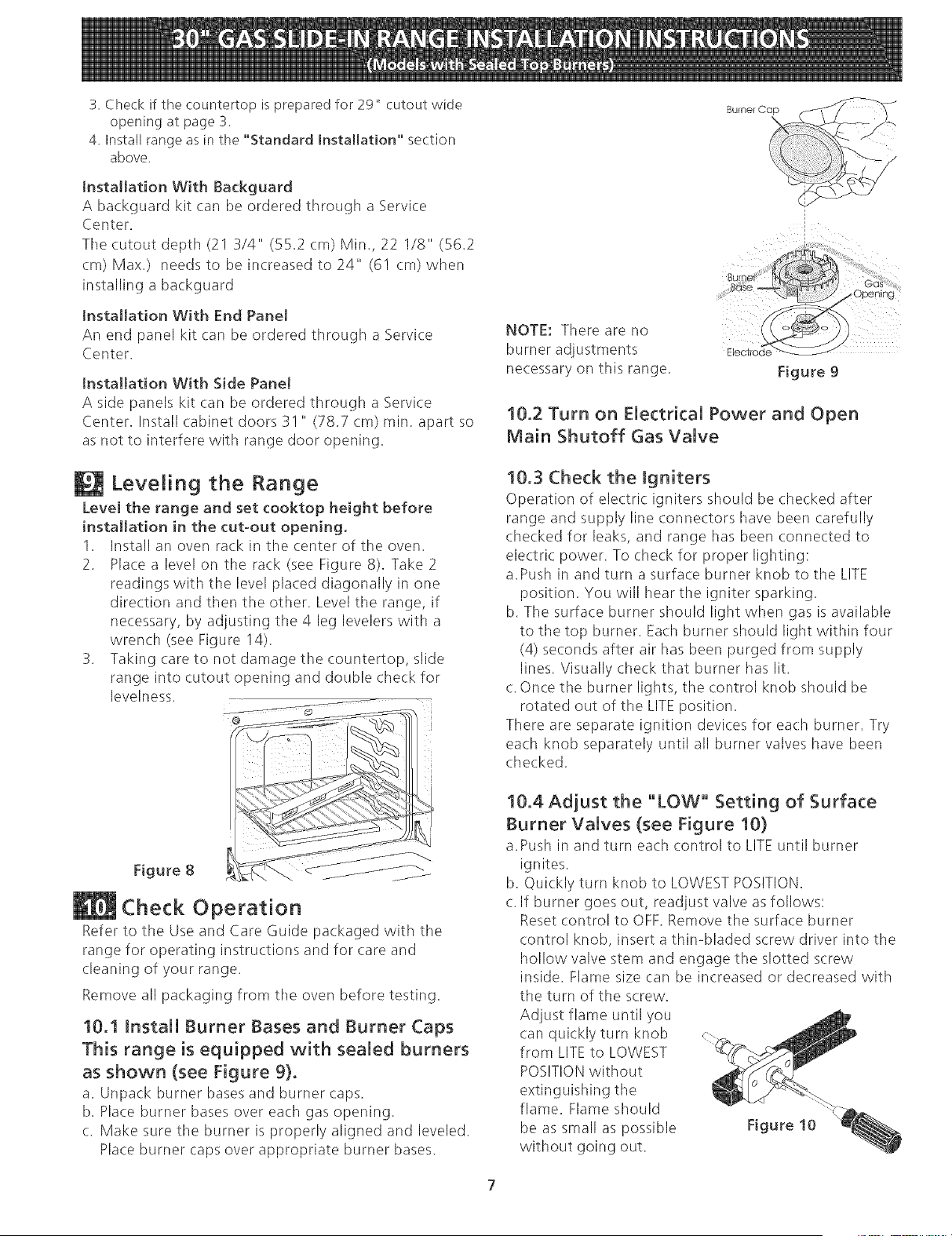
NOTE: There are no
burner adjustments
necessary on this range.
Figure 9
10.2 Turn on Electrical Power and Open
Main Shutoff 6as Valve
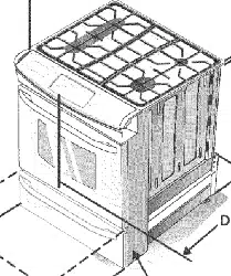
Leveling the Range
Level the range and set cooktop height before
installation in the cut-out opening.
1. Install an oven rack in the center of the oven.
2. Place a level on the rack (see Figure 8). Take 2
readings with the level placed diagonally in one
direction and then the other. Level the range, if
necessary, by adjusting the 4 leg levelers with a
wrench (see Figure 14).
3. Taking (are to not damage the countertop, slide
range into cutout opening and double check for
levelness.
@
i
Figure 8
Check Operation
Refer to the Use and Care Guide packaged with the
range for operating instructions and for (.are and
(.leaning of your range.
Remove all packaging from the oven before testing.
10.1 Install Burner Bases and Burner Caps
This range is equipped with sealed burners
as shown (see Figure 9}.
a. Unpack burner bases and burner caps.
b. Place burner bases over each gas opening.
c. Make sure the burner is properly aligned and leveled.
Place burner caps over appropriate burner bases.
10.3 Check the igniters
Operation of electric igniters should be checked after
range and supply line connectors have been carefully
checked for leaks, and range has been connected to
electric power. To check for proper lighting:
a.Push in and turn a surface burner knob to the LITE
position. You will hear the igniter sparking.
b. The surface burner should light when gas is available
to the top burner. Each burner should light within four
(4) seconds after air has been purged from supply
lines. Visually check that burner has lit.
c. Once the burner lights, the control knob should be
rotated out of the LITE position.
There are separate ignition devkes for each burner. Try
each knob separately until all burner valves have been
checked.
10.4 Adjust the "LOW" Setting of Surface
Burner Valves (see Figure 10}
a.Push in and turn each control to LITE until burner
ignites.
b. Quickly turn knob to LOWEST POSITION.
c. If burner goes out, readjust valve as follows:
Reset control to OFF. Remove the surface burner
control knob, insert a thin-bladed screw driver into the
hollow valve stem and engage the slotted screw
inside. Flame size (:an be increased or decreased with
the turn of the screw.
Adjust flame until you
can quickly turn knob
from LITE to LOWEST
POSITIONwithout
extinguishing the
flame. Flame should
be as small as possible
without going out.
Figure 10
Loading ...
Loading ...
Loading ...