Loading ...
Loading ...
Loading ...
13
outlet or install an outlet on
a nearby wall stud within the
wall).
• Hard wire the replace.
!
NOTE: Hard wiring can be done
by removing the plug from the
factory tted cord and completing
the wiring according to National and
Local Elecrical Codes.
WARNING: Do not attempt to
wire your own new outlets or circuits.
To reduce the risk of re, electric
shock or injury to persons, always
use a licensed electrician.
Ensure that the 3-Position Switch is
set to the Off position ("O") and that
the circuit on which the replace is to
be installed has the power cut off at
the service panel until installation is
complete.
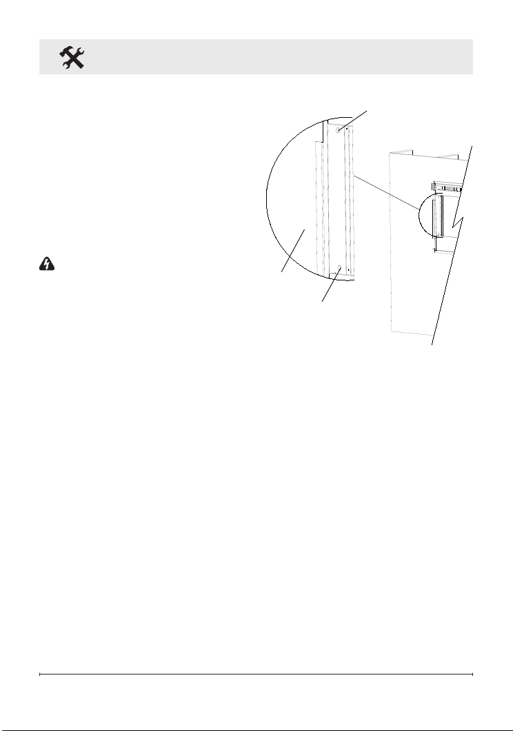
3. Lift replace and insert into
opening. The replace's
mounting trim should be ush
against the wall (Figure 8).
4. Use bubble level (supplied) to
level the replace within the
framing. Adjust as required.
5. Drive four (4) supplied mounting
screws through the four (4)
mounting holes located on the
inside surface of the replace
chassis, into wall studs (Figure
8).
Fireplace Installation
6. Refer to Front Glass
Installation section, for nal
installation procedures.
Front Glass Installation
1. Evenly distribute supplied
glass rock on the front tray of
the fireplace (Figure 9).
2. Carefully mount front glass
assembly so that the front
glass hooks (4) hang on the
front glass mounts on the
fireplace (4) (Figure 10).
3. Use the supplied two (2)
Phillips sheet metal screws
to fasten the glass assembly
tabs to the fireplace (Figure
11).
4. Ensure the fireplace's
Figure 8
Mounting hole
Mounting hole
Wall
surface
Loading ...
Loading ...
Loading ...