perator's
I:RnFrSMRN°
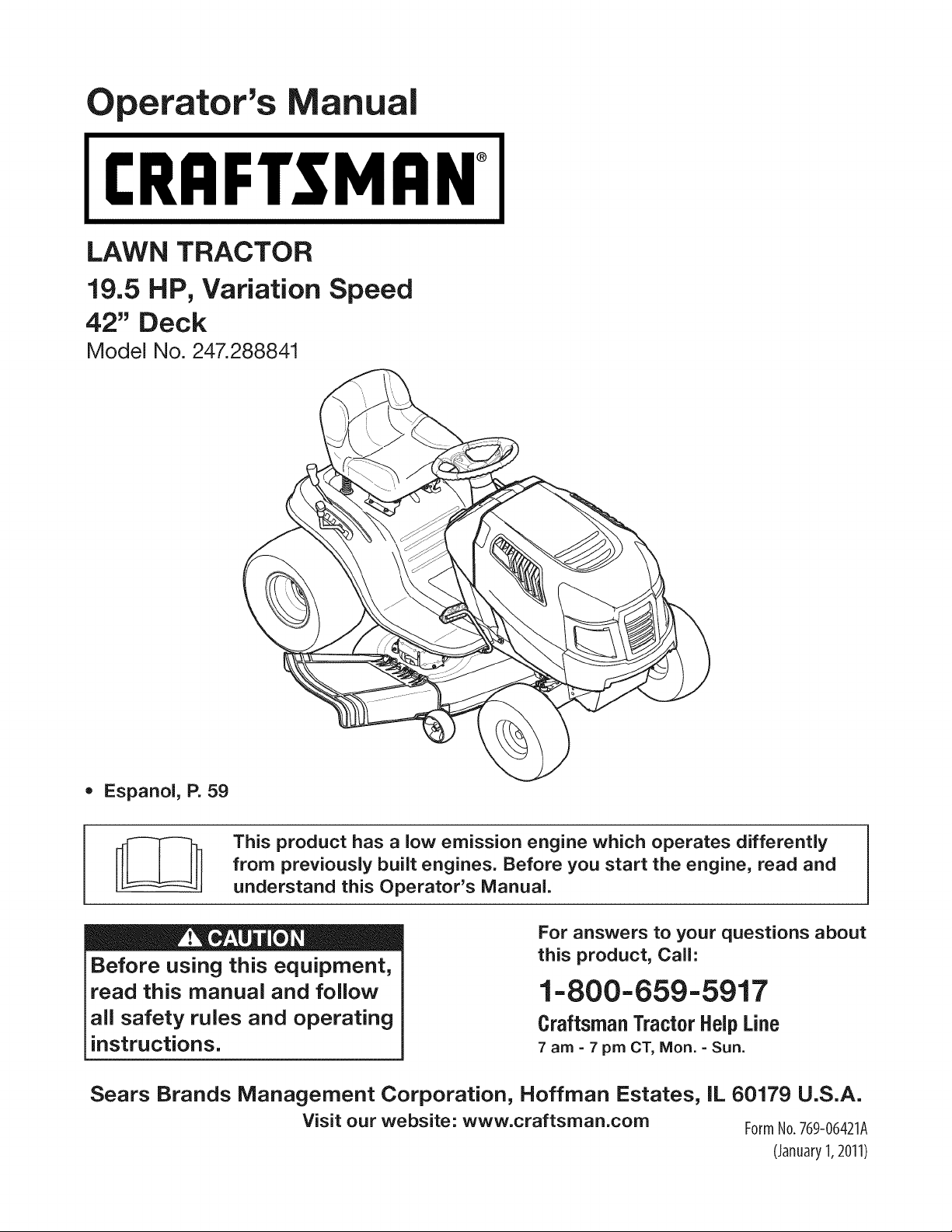
LAWN TRACTOR
19.5 HP, Variation Speed
42" Deck
Model No. 247.288841
• Espanol, P. 59
This product has a low emission engine which operates differently
from previously built engines. Before you start the engine, read and
understand this Operator's Manual.
Before using this equipment,
read this manual and follow
all safety rules and operating
instructions.
For answers to your questions about
this product, Call:
1-800=659=5917
Craftsman Tractor Help Line
7 am = 7 pm CT, Mort. =Sun.
Sears Brands Management Corporation, Hoffman Estates, IL 60179 U.S.A.
Visit our website: www.craftsman.com FormNo.769-06421A
(January1,2011)
Off-Season Storage ........................................................ 27
Trou bleshooting .............................................................. 28
Labels ............................................................................. 29
Parts List ......................................................................... 30
Espafiol ............................................................................ 59
Service Numbers ............................................. Back Cover
CRAFTSMAN FULL WARRANTY
FORTWOYEARSfromthe date of purchase,all non-expendablepartsof thisridingequipmentarewarrantedagainstany defectsin material
or workmanship.A defectivenon-expendablepart will receivefree in-homerepairor replacementif repairis impossible.
FORFIVEYEARSfromthe dateof purchase,the frameandfrontaxleof thisridingequipmentarewarrantedagainstanydefectsinmaterialor
workmanship.A defectiveframeor frontaxle will receivefreein-homerepairor replacementif repairis impossible.
FOR90 DAYSfromthe dateof purchase,the battery(an expendablepart)of this ridingequipmentis warrantedagainstanydefectsin material
or workmanship(ourtestingprovesthat it will not holda charge).A defectivebatterywill receivefreein-homereplacement.
ADDITIONALLIFETIMELIMITEDWARRANTYon CASTIRON FRONTAXLE (if equipped)
FORAS LONGASIT IS USEDby the originalownerafter the fifth yearfromthedate of purchase,the cast ironfrontaxle (if equipped)of this
ridingequipmentis warrantedagainstanydefectsin materialorworkmanship,Withproofof purchase,a defectivecastfrontaxle will receive
free in-homereplacement.
WARRANTYSERVICE
Forwarrantycoveragedetailsto obtainfree repairor replacement,call 1-800-659-5917or visit theweb site:www. craftsman.corn
Inallcasesabove,if partrepairor replacementis impossible,theridingequipmentwillbe replacedfreeof chargewiththe sameoranequivabntmodel.
All of the abovewarrantycoverageis voidif this ridingequipmentis ever usedwhileprovidingcommercialservicesor if rentedto another
person.
This warranty covers ONLYdefects in material and workmanship. Warranty coverage does NOTinclude:
• Expendableparts(exceptbattery)that can wearout fromnormaluse withinthe warrantyperiod,includingbutnot limitedto blades,
sparkplugs,air cleaners,belts,andoilfilters.
• Standardmaintenanceservicing,oil changes,ortune-ups,
• Tire replacementor repaircausedby puncturesfromoutsideobjects,suchas nails,thorns,stumps,or glass.
• Tire orwheel replacementor repairresultingfromnormalwear,accident,or improperoperationor maintenance.
• Repairsnecessarybecauseof operatorabuse,includingbutnot limitedto damagecausedbytowingobjectsbeyondthe capabilityof
the ridingequipment,impactingobjectsthatbendthe frame,axle assemblyor crankshaft,or over-speedingtheengine.
• Repairsnecessarybecauseof operatornegligence,includingbut not limitedto, electricalandmechanicaldamagecausedby
improperstorage,failureto use the propergradeandamountof engineoil, failureto keepthedeck clear of flammabledebris,or
failureto maintainthe ridingequipmentaccordingto the instructionscontainedinthe operator'smanual.
• Engine(fuelsystem)cleaningor repairscausedby fuel determinedto becontaminatedor oxidized(stale).In general,fuel shouldbe
usedwithin30 daysof its purchasedate.
• Normaldeteriorationandwearof the exteriorfinishes,or productlabel replacement.
Thiswarrantygivesyou specificlegalrights,and you mayalso haveotherrightswhichvaryfromstateto state.
Sears Brands ManagementCor _oration, Hoffman Estates, IL 60179
Model Number:
EngineOil: SAE30
Fuel: UnleadedGasoline
SparkPlug: Champion®RC12YC
Engine: Briggs& StrattonIntek®
Serial Number:
Dateof Purchase:
Recordthe modelnumber,serialnumber,
anddateof purchaseabove.
© KCD IP,LLC 2
Thissymbolpointsout importantsafetyinstructionswhich,if not
followed,couldendangerthepersonalsafetyand/orpropertyof
yourselfandothers. Readand followall instructionsin thismanual
beforeattemptingto operatethismachine.Failureto complywith
theseinstructionsmayresultin personalinjury.Whenyou seethis
symbol,HEEDITSWARNING!
CALIFORNIA PROPOSITION 65
EngineExhaust,someof its constituents,andcertainvehicle
componentscontainor emitchemicalsknownto Stateof California
to causecancerandbirthdefectsorother reproductiveharm.
Batteryposts,terminals,and relatedaccessoriescontainleadand
leadcompounds,chemicalsknownto the Stateof Californiato
causecancerand reproductiveharm.Washhandsafterhandling.
Thismachinewasbuiltto beoperatedaccordingto the safeopera-
tion practicesinthis manual.As with anytypeof powerequipment,
carelessnessorerroron the partof the operatorcan resultin serious
injury.Thismachineis capableof amputatingfingers,hands,toes
andfeet andthrowingdebris.Failureto observethe followingsafety
instructionscouldresultin seriousinjuryor death.
Your Responsibility--Restrictthe use of thispowermachineto
personswho read,understandand followthewarningsand instruc-
tionsin this manualandon the machine.
SAVE THESE INSTRUCTIONS!
GENERAL OPERATION
• Read,understand,andfollowall instructionson the machineand
in themanual(s)beforeattemptingto assembleandoperate.
Keepthis manualina safe placefor futureand regularreference
andfor orderingreplacementparts.
• Befamiliarwithall controlsand their properoperation.Knowhow
to stopthe machineand disengagethemquickly.
• Neverallowchildrenunder 14yearsold to operatethis machine.
Children14yearsoldandover shouldreadandunderstandthe
operationinstructionsandsafetyrulesin thismanualand should
betrainedandsupervisedbya parent.
• Neverallowadultsto operatethis machinewithoutproper
instruction.
• Tohelpavoidbladecontactor a thrownobjectinjury, keep
bystanders,helpers,childrenandpets at least 75feet fromthe
machinewhile it is in operation.Stopmachineif anyoneenters
the area.
• Thoroughlyinspectthe areawherethe equipmentis to be used.
Removeallstones,sticks,wire,bones,toys,andotherforeign
objectswhichcouldbe pickedup andthrownby the blade(s).
Thrownobjectscan causeseriouspersonalinjury.
• Planyour mowingpatternto avoiddischargeof materialtoward
roads,sidewalks,bystandersandthe like.Also,avoiddischarg-
ingmaterialagainstawall orobstructionwhichmaycause
dischargedmaterialto ricochetback towardthe operator.
• Alwayswear safetyglassesor safetygogglesduring operation
andwhile performingan adjustmentor repairto protectyoureyes.
Thrownobjectswhichricochetcancause seriousinjuryto the
eyes.
• Wearsturdy,rough-soledwork shoesandclose-fittingslacksand
shirts.Loosefittingclothesandjewelrycanbe caughtin movable
parts.Neveroperatethismachinein barefeet orsandals.
• Be awareof the mowerand attachmentdischargedirectionand
do not pointit at anyone.Donot operatethe mowerwithoutthe
dischargecover orentiregrass catcherin its properplace.
Donot put handsor feet nearrotatingpartsor underthe cutting
deck. Contactwiththe blade(s)can amputatehandsandfeet.
A missingor damageddischargecovercan causebladecontact
or thrownobjectinjuries.
• Stoptheblade(s)whencrossinggraveldrives,walks,or roads
andwhile notcuttinggrass.
• Watchfor trafficwhenoperatingnearorcrossingroadways.This
machineis not intendedfor useonany public roadway.
• Donot operatethe machinewhile underthe influenceof alcohol
or drugs.
• Mowonly indaylightorgoodartificiallight.
Nevercarrypassengers.
• Disengageblade(s)beforeshiftinginto reverse.Backup slowly.
Alwayslookdownandbehindbeforeandwhile backingto avoida
back-overaccident.
3
• Slowdownbeforeturning.Operatethe machinesmoothly.Avoid
erraticoperationandexcessivespeed.
Disengageblade(s),set parkingbrake,stopengineand waituntil
the blade(s)cometo a completestop beforeremovinggrass
catcher,emptyinggrass,uncloggingchute,removinganygrassor
debris,or makinganyadjustments.
Neverleavea runningmachineunattended.Alwaysturnoff
blade(s),setparkingbrake,stopengine andremovekeybefore
dismounting.
Useextracare whenloadingorunloadingthe machineintoa
trailerortruck.Thismachineshouldnot bedrivenup or down
ramp(s),becausethe machinecouldtip over,causingserious
personalinjury.The machinemustbe pushedmanuallyon
ramp(s)to loador unloadproperly.
Mufflerandenginebecomehotandcan causea burn.Do not
touch.
Checkoverheadclearancescarefullybeforedrivingunderlow
hangingtree branches,wires,door openingsetc.,wherethe
operatormaybestruckor pulledfromthe machine,which could
resultinseriousinjury.
Disengageall attachmentclutchesanddepressthe brakepedal
completelybeforeattemptingto start engine.
Yourmachineisdesignedto cutnormalresidentialgrass of a
heightnomorethan 10".Do not attemptto mowthroughunusually
tall,dry grass(e.g.,pasture)or piles of dry leaves.Drygrassor
leavesmaycontactthe engineexhaustand/or builduponthe
mowerdeckpresentinga potentialfire hazard.
Useonlyaccessoriesandattachmentsapprovedfor this machine
by the machinemanufacturer.Read,understandandfollowall
instructionsprovidedwith the approvedaccessoryor attachment.
Fora list of approvedaccessoriesandattachments,call 1-800-
659-5917.
Dataindicatesthatoperators,age60yearsandabove,are
involvedin a largepercentageof ridingmower-relatedinjuries.
Theseoperatorsshouldevaluatetheirabilityto operatethe riding
mowersafelyenoughto protectthemselvesand othersfrom
seriousinjury.
If situationsoccurwhich arenot coveredinthismanual,usecare
andgoodjudgment.Contact1-800-659-5917for informationand
assistance.
SLOPE OPERATION
Slopesarea majorfactorrelatedto lossof controlandtip-over
accidentswhichcan result insevereinjuryor death.Allslopes require
extracaution.If youcannotbackupthe slopeor if youfeel uneasyon
it, do not mowit.
Foryoursafety,use the SlopeGuide includedas partof this manual
to measureslopesbeforeoperatingthis machineona slopedor hilly
area. If the slopeis greaterthan15degreesas shownonthe Slope
Guide,do notoperatethis machineonthat areaor seriousinjurycould
result.
Do:
o
Mowupand down slopes,not across.Exerciseextremecaution
whenchangingdirectionon slopes.
• Watchfor holes,ruts,bumps,rocks,orother hiddenobjects.
Uneventerraincouldoverturnthe machine.Tallgrasscan hide
obstacles.
Useslowspeed.Choosea lowenoughspeedsettingso that
you will nothaveto stopor shiftwhileon the slope.Tiresmay
lose tractionon slopeseventhoughthe brakesare functioning
properly.Alwayskeepmachinein gearwhen goingdownslopes
to takeadvantageof enginebrakingaction.
• Followthe manufacturer'srecommendationsfor wheelweights
or counterweightsto improvestability.Forrecommendations,call
1-800-659-5917.
• Useextra carewithgrass catchersor otherattachments.These
can changethe stabilityof the machine.
Keepallmovementonthe slopesslowandgradual.Do not make
suddenchangesinspeedor direction.Rapidengagementor
brakingcouldcausethe frontof the machineto lift and rapidlyflip
overbackwardswhichcouldcauseseriousinjury.
• Avoidstartingorstoppingona slope.Iftireslosetraction,disen-
gagethe blade(s)andproceedslowlystraightdownthe slope.
DoNot:
• Donot turnon slopesunlessnecessary;then, turnslowlyand
graduallydownhill,if possible.
• Donot mowneardrop-offs,ditchesor embankments.The mower
could suddenlyturnover if a wheelis overthe edgeof a cliff,
ditch,or if an edge cavesin.
• Donot try to stabilizethe machineby puttingyourfooton the
ground.
• Donot usea grasscatcheron steepslopes.
• Donot mowon wetgrass.Reducedtractioncouldcausesliding.
• Donot attemptto coastdownhill.Over-speedingmaycausethe
operatorto lose controlof the machineresultingin seriousinjury
or death.
• Donot towheavypull behindattachments(e.g. loadeddumpcart,
lawn roller,etc.)on slopesgreaterthan5 degrees.Whengoing
down hill,the extraweighttendsto pushthe tractorand may
causeyou to loosecontrol(e.g.tractormayspeedup, brakingand
steeringabilityare reduced,attachmentmayjack-knifeandcause
tractorto overturn).
4
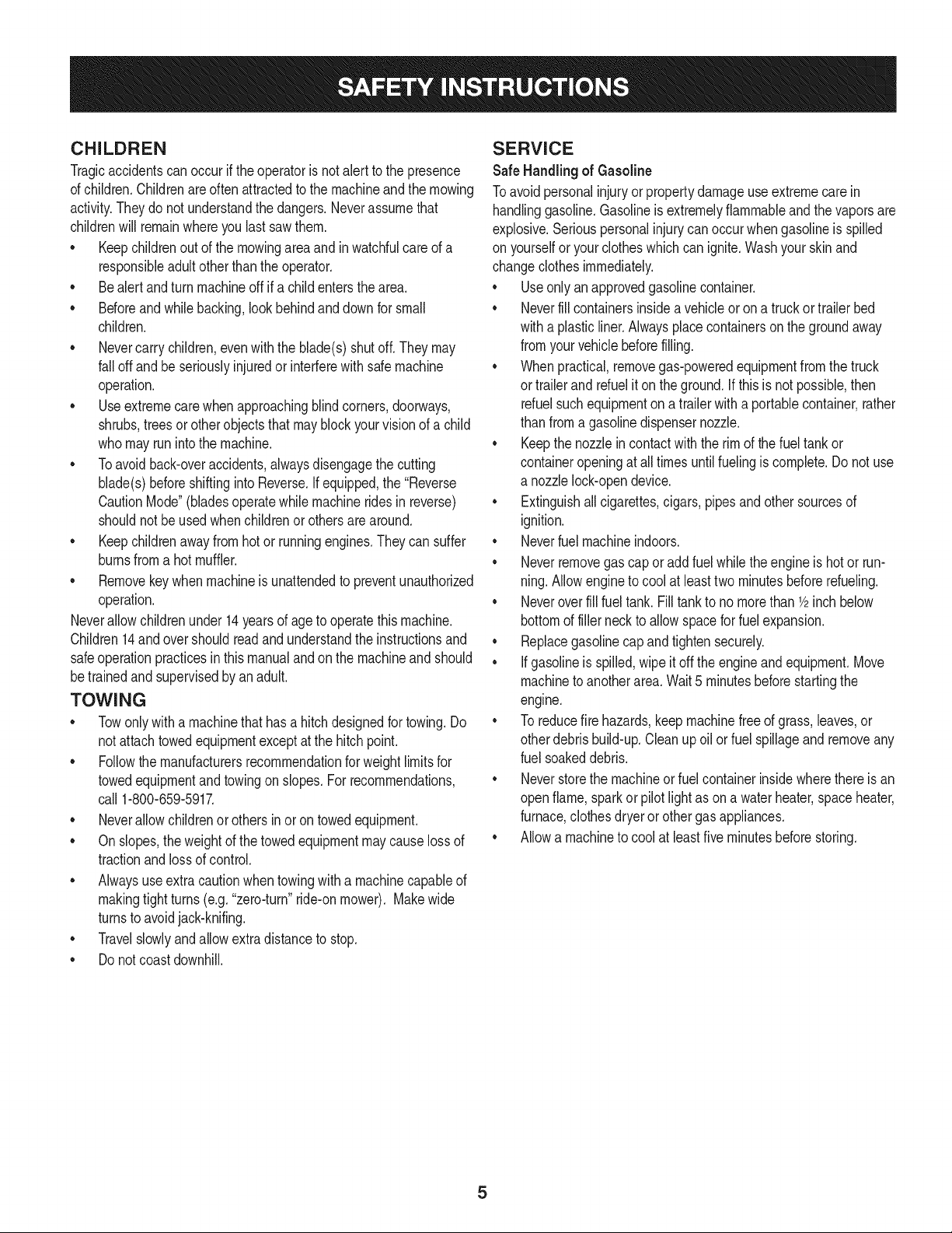
CHILDREN
Tragicaccidentscanoccurifthe operatoris notalert to the presence
of children.Childrenareoftenattractedto the machineand the mowing
activity.Theydo notunderstandthe dangers.Neverassumethat
childrenwill remainwhereyou lastsawthem.
• Keepchildrenout of the mowingareaand inwatchfulcare of a
responsibleadultotherthanthe operator.
• Bealert andturnmachineoff ifa childentersthe area.
• Beforeand whilebacking,lookbehindanddownfor small
children.
Nevercarrychildren,evenwiththe blade(s)shutoff.Theymay
fall offandbe seriouslyinjuredorinterferewith safemachine
operation.
• Useextremecarewhenapproachingblindcorners,doorways,
shrubs,treesorotherobjectsthatmayblockyourvisionof a child
whomayrunintothe machine.
Toavoidback-overaccidents,alwaysdisengagethe cutting
blade(s)beforeshiftingintoReverse.Ifequipped,the "Reverse
CautionMode"(bladesoperatewhilemachineridesinreverse)
shouldnotbe usedwhenchildrenor othersarearound.
Keepchildrenawayfromhotor runningengines.Theycansuffer
burnsfroma hotmuffler.
• Removekeywhenmachineisunattendedto preventunauthorized
operation.
Neverallowchildrenunder14yearsof ageto operatethis machine.
Children14andovershouldreadandunderstandthe instructionsand
safeoperationpracticesin thismanualandon the machineand should
betrainedandsupervisedbyan adult.
TOWING
Towonlywitha machinethathasa hitch designedfor towing.Do
not attachtowedequipmentexceptat the hitchpoint.
Followthe manufacturersrecommendationforweightlimitsfor
towedequipmentand towingonslopes.For recommendations,
call 1-800-659-5917.
Neverallowchildrenor othersin oron towedequipment.
Onslopes,theweightof thetowedequipmentmaycauselossof
tractionandlossof control.
Alwaysuseextracautionwhentowingwitha machinecapableof
makingtightturns (e.g."zero-turn"ride-onmower). Makewide
turnsto avoidjack-knifing.
Travelslowlyandallowextradistanceto stop.
Do notcoastdownhill.
SERVICE
SafeHandlingof Gasoline
Toavoidpersonalinjuryor propertydamageuse extremecarein
handlinggasoline.Gasolineisextremelyflammableand the vaporsare
explosive.Seriouspersonalinjurycanoccur whengasolineis spilled
on yourselforyour clotheswhich can ignite.Washyourskinand
changeclothesimmediately.
• Useonly anapprovedgasolinecontainer.
Neverfill containersinsidea vehicleor on a truckortrailer bed
witha plasticliner.Alwaysplacecontainerson the groundaway
fromyourvehiclebeforefilling.
Whenpractical,removegas-poweredequipmentfromthe truck
or trailerandrefueliton theground.If this isnot possible,then
refuelsuchequipmentona trailerwith a portablecontainer,rather
than froma gasolinedispensernozzle.
Keepthe nozzleincontactwith the rim of the fueltank or
containeropeningat all timesuntilfuelingiscomplete.Donot use
a nozzlelock-opendevice.
Extinguishall cigarettes,cigars,pipesandothersourcesof
ignition.
• Neverfuel machineindoors.
Neverremovegascap or add fuelwhilethe engineis hotor run-
ning.Allowengineto coolat leasttwo minutesbeforerefueling.
Neveroverfill fuel tank. Filltankto no morethan 1/2inchbelow
bottomof filler neckto allowspaceforfuel expansion.
• Replacegasolinecap andtightensecurely.
• If gasolineis spilled,wipeitoff the engineandequipment.Move
machineto anotherarea.Wait 5 minutesbeforestartingthe
engine.
• To reducefire hazards,keepmachinefree of grass,leaves,or
otherdebrisbuild-up.Cleanup oilor fuel spillageandremoveany
fuel soakeddebris.
• Neverstorethe machineor fuelcontainerinsidewherethere isan
openflame,sparkor pilotlight as ona waterheater,spaceheater,
furnace,clothesdryeror othergasappliances.
Allowa machineto coolat least fiveminutesbeforestoring.
GeneralService
• Neverrunanengineindoorsorinapoorlyventilatedarea.Engine
exhaustcontainscarbonmonoxide,anodorless,anddeadlygas.
• Beforecleaning,repairing,orinspecting,makecertainthe
blade(s)andallmovingpartshavestopped.Disconnectthespark
plugwireandgroundagainsttheenginetopreventunintended
starting.
• Periodicallychecktomakesurethebladescometocomplete
stopwithinapproximately(5)fivesecondsafteroperatingthe
bladedisengagementcontrol.Ifthebladesdonotstopwithinthe
thistimeframe,yourmachineshouldbeservicedprofessionally
byaSearsorotherqualifiedservicedealer.
• Checkbrakeoperationfrequentlyasitissubjectedtowearduring
normaloperation.Adjustandserviceasrequired.
• Checktheblade(s)andenginemountingboltsatfrequent
intervalsforpropertightness.Also,visuallyinspectblade(s)
fordamage(e.g.,excessivewear,bent,cracked).Replacethe
blade(s)withtheoriginalequipmentmanufacturer's(O.E.M.)
blade(s)only,listedinthismanual.Useofpartswhichdonot
meettheoriginalequipmentspecificationsmayleadtoimproper
performanceandcompromisesafety!
• Mowerbladesaresharp.Wrapthebladeorweargloves,anduse
extracautionwhenservicingthem.
• Keepallnuts,bolts,andscrewstighttobesuretheequipmentis
insafeworkingcondition.
• Nevertamperwiththe safetyinterlocksystemor othersafety
devices.Checktheir properoperationregularly.
• Afterstrikinga foreignobject,stopthe engine,disconnectthe
sparkplugwire(s)andgroundagainstthe engine.Thoroughly
inspectthe machinefor anydamage.Repairthe damagebefore
startingandoperating.
• Neverattemptto makeadjustmentsor repairsto the machine
whilethe engineis running.
• Grasscatchercomponentsandthe dischargecoverare subject
to wearanddamagewhich couldexposemovingparts or allow
objectsto bethrown.Forsafetyprotection,frequentlycheck
componentsand replaceimmediatelywithoriginalequipment
manufacturer's(O.E.M.)partsonly,listed inthis manual.Useof
partswhichdo not meetthe originalequipmentspecificationsmay
leadto improperperformanceandcompromisesafety!
• Donot changethe enginegovernorsettingsorover-speedthe
engine.The governorcontrolsthe maximumsafe operatingspeed
of the engine.
Maintainor replacesafetyandinstructionlabels,as necessary.
• Observeproperdisposallawsandregulationsfor gas,oil, etc.to
protecttheenvironment.
• Accordingto the ConsumerProductsSafetyCommission(CPSC)
andthe U.S.EnvironmentalProtectionAgency(EPA),this product
has anAverageUsefulLifeof seven(7)years,or 270hours
of operation.At the end of the AverageUsefulLife,buy anew
machineor havethe machineinspectedannuallybya Searsor
otherqualifiedservicedealerto ensurethat all mechanicaland
safetysystemsareworkingproperlyand not wornexcessively.
Failureto doso can resultinaccidents,injuriesor death.
DO NOT MODIFY ENGINE
Toavoid seriousinjuryor death,do notmodifyengineinanyway.
Tamperingwiththe governorsettingcanlead to a runawayengineand
causeit to operateat unsafespeeds.Nevertamperwith factorysetting
of enginegovernor.
NOTICE REGARDING EMISSIONS
Engineswhicharecertifiedto complywith Californiaand federal
EPAemissionregulationsfor SORE(SmallOffRoadEquipment)are
certifiedto operateon regularunleadedgasoline,andmay include
the followingemissioncontrol systems:EngineModification(EM)and
ThreeWayCatalyst(TWO)if so equipped.
SPARK ARRESTOR
Thismachineis equippedwithan internalcombustionengineand
shouldnotbe usedonor nearanyunimprovedforest-covered,
brushcoveredor grass-coveredland unlessthe engine'sexhaust
systemisequippedwitha sparkarrestormeetingapplicablelocalor
statelaws(if any).
Ifa sparkarrestoris used,it shouldbe maintainedin effectiveworking
orderby the operator.Inthe Stateof Californiatheaboveis required
by law (Section4442of the CaliforniaPublicResourcesCode). Other
statesmayhavesimilarlaws.Federallaws applyonfederallands.
A sparkarrestorfor the muffleris availablethroughyournearestSears
PartsandRepairServiceCenter.
6
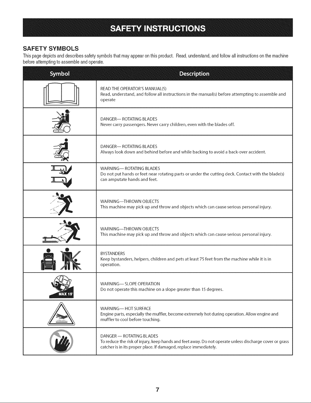
SAFETY SYMBOLS
Thispagedepictsanddescribessafety symbolsthat mayappearon this product. Read,understand,and followall instructionson the machine
beforeattemptingto assembleandoperate.
O
A
READ THE OPERATOR'S MANUAL(S)
Read, understand, and follow all instructions in the manual(s) before attempting to assemble and
operate
DANGER-- ROTATING BLADES
Never carry passengers. Never carry children, even with the blades off.
DANGER-- ROTATING BLADES
Always look down and behind before and while backing to avoid a back-over accident.
WARNING-- ROTATING BLADES
Do not put hands or feet near rotating parts or under the cutting deck. Contact with the blade(s)
can amputate hands and feet.
WARNING--THROWN OBJECTS
This machine may pick up and throw and objects which can cause serious personal injury.
WARNING--THROWN OBJECTS
This machine may pick up and throw and objects which can cause serious personal injury.
BYSTANDERS
Keep bystanders, helpers, children and pets at least 75 feet from the machine while it is in
operation.
WARNING-- SLOPE OPERATION
Do not operate this machine on a slope greater than 15 degrees.
WARNING-- HOT SURFACE
Engine parts, especially the muffler, become extremely hot during operation. Allow engine and
muffler to cool before touching.
DANGER- ROTATING BLADES
To reduce the risk of injury, keep hands and feet away. Do not operate unless discharge cover or grass
catcher is in its proper place. If damaged, replace immediately.
7
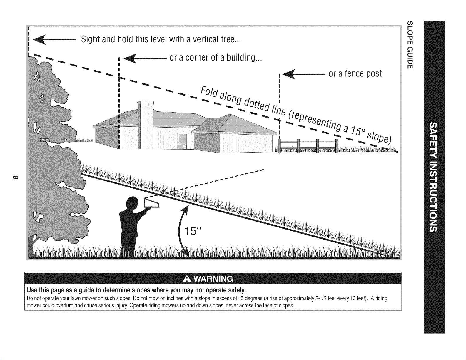
Sight and hold this levelwith a vertical tree...
or a corner of a building...
or a fence post
II "_" "_ _ . a 15o,,,
15°
0
rrl
rrl
Use this page as a guide to determine slopes where you may not operate safely.
Donot operateyourlawnmoweron such slopes.Do notmowon inclineswitha slope inexcessof 15degrees(a rise of approximately2ol/2 feetevery10feet). A riding
mowercouldoverturnand causeseriousinjury.Operateridingmowersupanddownslopes,neveracrossthe faceof slopes.
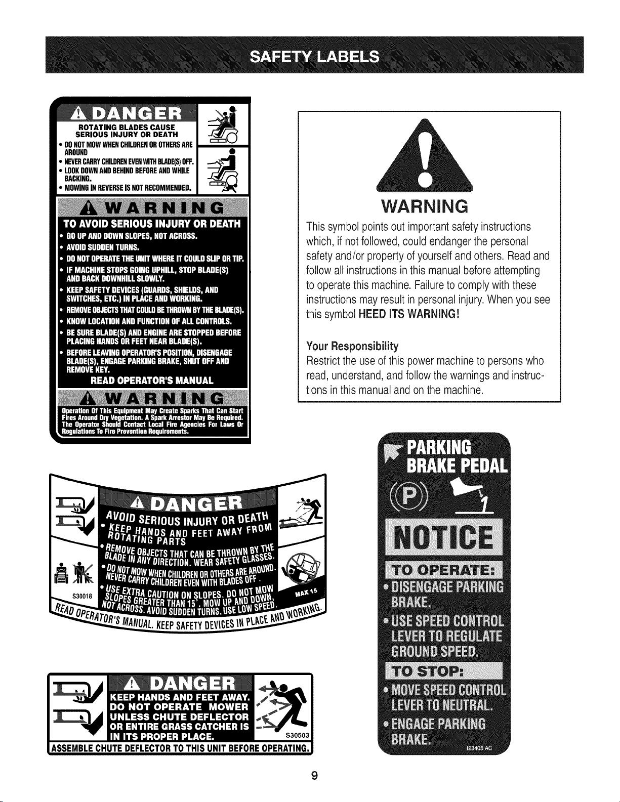
ROTATING BLADES CAUSE
SERIOUS INJURY OR DEATH
DONOTMOWWHENCHILDRENOROTHERSARE
AROUND
NEVERCARRYCHILDRENEVENWITHBLADE(S)OFF.
LOOKDOWNANDBEHINDBEFOREANDWHILE
BACKING.
MOWINGINREVERSEISNOTRECOMMENDED.
WARNING
This symbol points out important safety instructions
which, if notfollowed, could endangerthe personal
safety and/or property of yourself and others. Read and
follow all instructions inthis manualbefore attempting
to operatethis machine. Failure to comply with these
instructions may result in personal injury.When you see
this symbol HEED ITS WARNING!
Your Responsibility
Restrictthe use of this power machineto persons who
read, understand, and follow the warnings and instruc-
tions in this manual and on the machine.
9
IMPORTANT:Yourtractoris shippedwithmotoroil in theengine.
However,you MUSTcheckthe oil levelbeforeoperating.Referto the
Service& Maintenancesectionfor instructionson checkingtheoil
level.
Attaching the Battery Cables
CALIFORNIA PROPOSITION 65
Batteryposts,terminals,andrelatedaccessoriescontainlead and
leadcompounds,chemicalsknownto the Stateof Californiato
causecancerand reproductiveharm.Washhandsafter handling.
Whenattachingbatterycables,alwaysconnectthe POSITIVE(Red)
wireto its terminalfirst,followedby the NEGATIVE(Black)wire.
Forshippingreasons,bothbatterycables onyourequipmenthave
beenleft disconnectedfromthe terminalsat the factory.Toconnect
the batterycables,proceedas follows:
NOTE:Thepositivebatteryterminalis markedPos.(+).The negative
batteryterminalis markedNeg. (i).
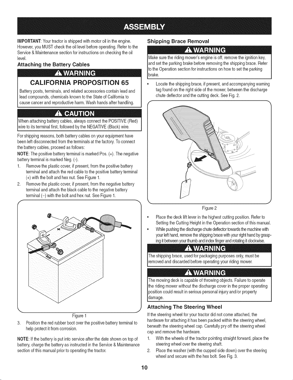
1. Removethe plasticcover,if present,fromthe positivebattery
terminaland attachthe redcableto the positivebatteryterminal
(+)withthe bolt andhexnut.See Figure1.
2. Removethe plasticcover,if present,fromthe negativebattery
terminaland attachthe blackcableto the negativebattery
terminal(-) withthe bolt andhex nut.See Figure1.
f
J
Figure1
3. Positionthe red rubberbootoverthe positivebatteryterminalto
helpprotectit fromcorrosion.
NOTE:If thebatteryis put into serviceafterthe dateshownon topof
battery,chargethe batteryas instructedinthe Service& Maintenance
sectionof this manualpriorto operatingthe tractor.
Shipping Brace Removal
Makesurethe ridingmower'sengineis off, removetheignitionkey,
andset the parkingbrakebeforeremovingthe shippingbrace.Refer
Itothe Operationsectionfor instructionson howto setthe parking
lbrake.
• Locatethe shippingbrace,if present,and accompanyingwarning
tag foundonthe rightsideof the mower,betweenthe discharge
chutedeflectorandthe cuttingdeck. SeeFig. 2.
Figure2
Placethe decklift leverin the highestcuttingposition.Referto
SettingtheCuttingHeightin the Operationsectionof this manual.
Whilepushingthedischargechuteddlectortowardsthemachinewith
yourlefthand,removetheshippingbracewithyourrighthandbygrasp-
ingitbetweenyourthumbandindexfingerandrotatingitclockwise.
The shippingbrace,usedfor packagingpurposesonly,mustbe
removedand discardedbeforeoperatingyour ridingmower.
The mowingdeck iscapableof throwingobjects. Failureto operate
the ridingmowerwithoutthe dischargecoverin the properoperating
Ipositioncould resultin seriouspersonalinjuryand/orproperty
ldamage.
Attaching The Steering Wheel
Ifthe steeringwheelfor yourtractordid notcomeattached,the
hardwarefor attachingit has beenpackedwithinthe steeringwheel,
beneaththe steeringwheelcap.Carefullypry off the steeringwheel
cap andremovethe hardware.
1. Withthe wheelsof the tractorpointingstraightforward,placethe
steeringwheeloverthe steeringshaft.
2. Placethe washer(withthe cuppedsidedown)overthe steering
wheeland securewiththe hex bolt. SeeFig.3.
10
f..-
\
Figure3
3. Placethe steeringwheelcap overthe center of the steering
wheeland pushdownwarduntilit "clicks"intoplace.
Attaching The Seat
NOTE:Forshippingreasons,the seatis eitherfastenedtothe tractor
seat'spivotbracketwitha plastictie, or mountedbackwardto the pivot
bracket.Ineithercase,free the seatfromits shippingpositionbeing
carefulnotto bendor kinkthe wiringharnessandfollow theinstruc-
tionsbelowto attach it.
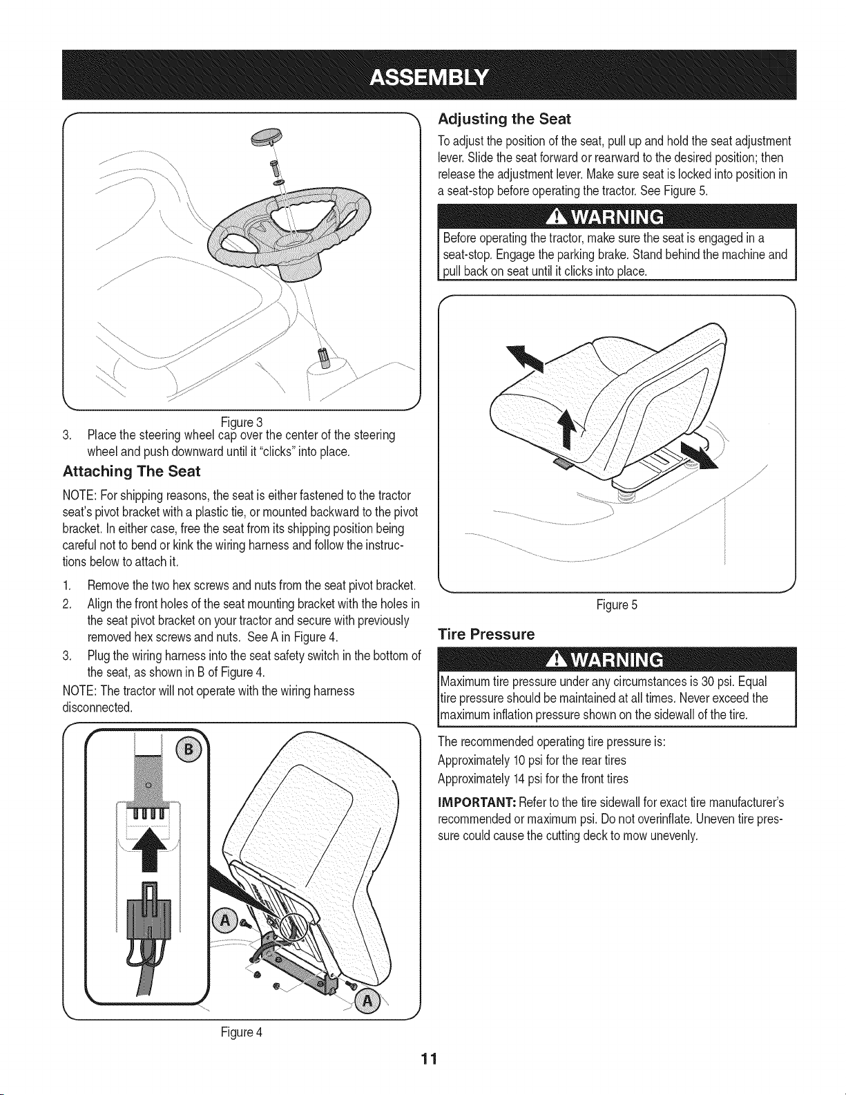
1. Removethetwo hexscrewsandnutsfromthe seatpivot bracket.
2. Alignthefront holesof the seatmountingbracketwith the holesin
the seat pivotbracketon yourtractorand securewith previously
removedhex screwsandnuts. See A in Figure4.
3. Plugthe wiringharnessintothe seatsafetyswitchinthe bottomof
the seat,as shownin B of Figure4.
NOTE:The tractorwill not operatewith the wiringharness
disconnected.
Adjusting the Seat
Toadjustthe positionof the seat,pull upand holdthe seatadjustment
lever.Slidethe seatforwardor rearwardto thedesiredposition;then
releasethe adjustmentlever.Makesure seatis lockedintopositionin
a seat-stopbeforeoperatingthe tractor.SeeFigure5.
Beforeoperatingthe tractor,makesurethe seat is engagedin a
seat-stop.Engagethe parkingbrake.Standbehindthe machineand
pull backon seatuntil it clicksintoplace.
Figure5
Tire Pressure
Maximumtire pressureunderany circumstancesis 30 psi.Equal
tire pressureshouldbe maintainedat all times.Neverexceedthe
_maxmum nfat onpressureshownonthe s dewa of thet re.
The recommendedoperatingtire pressureis:
Approximately10psi forthe reartires
Approximately14psifor the fronttires
iMPORTANT: Referto the tire sidewallfor exacttire manufacturer's
recommendedor maximumpsi.Donot overinfiate.Uneventirepres-
surecouldcausethe cuttingdeckto mowunevenly.
Figure4
11
B
C
D
E
G
Figure6
F
J
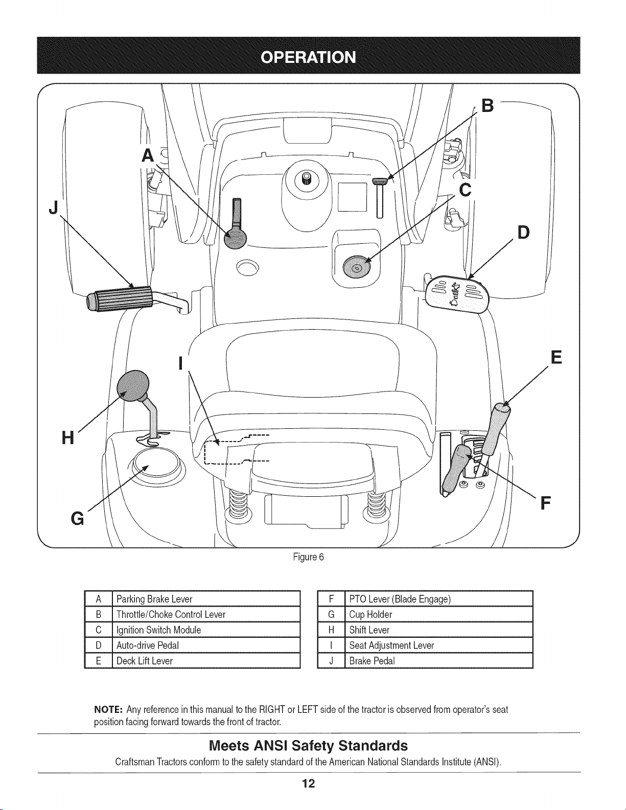
A ParkingBrakeLever
B Throttle/ChokeControlLever
C IgnitionSwitchModule
D Auto-drivePedal
E DeckLift Lever
F PTOLever(BladeEngage)
G Cup Holder
H ShiftLever
I SeatAdjustmentLever
J BrakePedal
NOTE: Any referencein this manualto the RIGHTor LEFTsideof the tractoris observedfromoperator'sseat
positionfacingforwardtowardsthe frontof tractor.
Meets ANSi Safety Standards
CraftsmanTractorsconformto the safetystandardof theAmericanNationalStandardsInstitute(ANSI).
12
PARKING BRAKE LEVER
Toset the parkingbrake: Fullydepressthe brakepedal. Movethe
parkingbrakeleverintothe parkingbrakeposition.Releasethe brake
pedalto allowthe parkingbraketo engage.
To release the parkingbrake: Depressthe brakepedalandthe park-
ingbrakeleverwill moveoutof the parkingbrakepositionon its own.
Theparkingbrakewillthen bereleased.Releasethe brakepedal.
NOTE: The parkingbrakemustbe set if the operatorleavesthe seat
withthe enginerunningor the enginewill automaticallyshutoff.
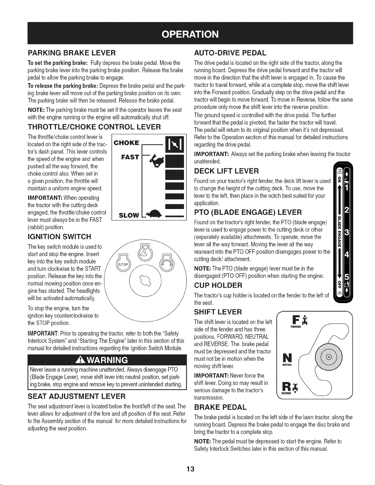
THROTTLE/CHOKE CONTROL LEVER
Thethrottle/chokecontrolleveris
locatedonthe right sideof the trac-
tor'sdash panel.This levercontrols
the speedof the engineand when
pushedall thewayforward,the
chokecontrolalso.Whenset in
a givenposition,thethrottlewill
maintaina uniformenginespeed.
IMPORTANT: Whenoperating
the tractorwiththe cuttingdeck
engaged,thethrottle/chokecontrol
levermustalwaysbe in the FAST
(rabbit)position.
IGNITION SWITCH
Thekeyswitchmoduleisusedto
startand stopthe engine.Insert
keyintothe keyswitchmodule
andturnclockwiseto theSTART
position.Releasethe keyintothe
normalmowingpositiononceen-
ginehasstarted.The headlights
will beactivatedautomatically.
Tostopthe engine,turnthe
ignitionkeycounterclockwiseto
the STOPposition.
CHOKE
FAST
SLOW
l=, m
IMPORTANT:Prior to operatingthe tractor,referto boththe "Safety
InterlockSystem"and"StartingThe Engine"laterinthissectionof this
manualfor detailedinstructionsregardingthe IgnitionSwitchModule.
Neverleavea runningmachineunattended.AlwaysdisengagePTO
(BladeEngageLever),moveshiftleverintoneutralposition,setpark-
ingbrake,stopengineandremovekeyto preventunintendedstarting.
SEAT ADJUSTMENT LEVER
Theseatadjustmentleveris locatedbelowthe front/leftof the seat.The
leverallowsfor adjustmentof the foreandaft positionof the seat.Refer
to theAssemblysectionof themanual formoredetailedinstructionsfor
adjustingthe seatposition.
AUTO-DRIVE PEDAL
The drivepedalislocatedonthe rightside of the tractor,alongthe
runningboard.Depressthe drivepedalforwardandthe tractorwill
moveinthe directionthatthe shiftleveris engagedin. Tocausethe
tractorto travelforward,whileat a completestop,movethe shift lever
intothe Forwardposition.Graduallysteponthe drivepedaland the
tractorwill beginto moveforward.Tomovein Reverse,followthe same
procedureonlymovetheshift leverintothe reverseposition.
The groundspeediscontrolledwiththe drivepedal.Thefurther
forwardthatthe pedalis pivoted,thefasterthe tractorwill travel.
The pedalwill returnto its originalpositionwhenit'snot depressed.
Referto the Operationsectionof thismanualfor detailedinstructions
regardingthedrive pedal.
IMPORTANT= Alwaysset the parkingbrakewhenleavingthe tractor
unattended.
DECK LIFT LEVER
Foundonyour tractor'srightfender,the deckliftleveris used
to changethe heightof the cuttingdeck.To use,movethe
leverto the left, thenplaceinthe notchbestsuitedfor your
application.
PTO (BLADE ENGAGE) LEVER
Foundonthe tractor'srightfender,the PTO(bladeengage)
leveris usedto engagepowerto the cuttingdeckor other
(separatelyavailable)attachments.Tooperate,movethe
leverall thewayforward.Movingthe leverallthe way
rearwardintothe PTOOFFpositiondisengagespowerto the
cuttingdeck/attachment.
NOTE=The PTO(bladeengage)levermustbe in the
disengaged(PTOOFF)positionwhenstartingthe engine.
CUP HOLDER
The tractor'scup holderis locatedon the fenderto the left of
the seat.
SHIFT LEVER
The shift leveris locatedonthe left
sideof the fenderand hasthree
positions,FORWARD,NEUTRAL
and REVERSE.The brakepedal
mustbedepressedandthe tractor
mustnotbe in motionwhenthe
movingshift lever.
IMPORTANT: Neverforcethe
shiftlever.Doingso mayresultin
seriousdamageto the tractor's
transmission.
REVERSE
_J
BRAKE PEDAL
The brakepedalis locatedon the leftside of the lawntractor,alongthe
runningboard.Depressthe brakepedalto engagethe discbrakeand
bringthe tractorto a completestop.
NOTE=The pedalmustbe depressedto startthe engine.Referto
SafetyInterlockSwitcheslaterin thissectionof thismanual.
13
GAS AND OiL FILL-UP
0il
IMPORTANT: Yourtractoris shippedwithmotoroil inthe engine.
However,you MUSTcheckthe oil levelbeforeoperating.Becareful
notto overfill.
Forinstructionsonhowto checkthe engineoil, referto CheckingThe
EngineOilin the ServiceandMaintenancesectionof this manual.
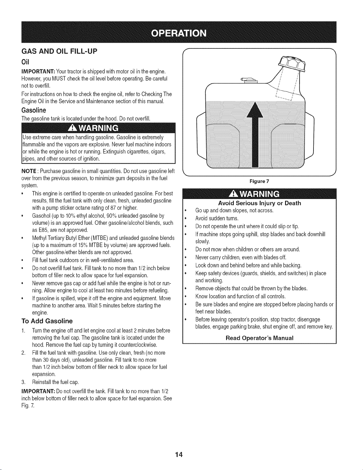
Gasoline
Thegasolinetankis locatedunderthe hood.Do notoverfill.
Useextremecarewhenhandlinggasoline.Gasolineis extremely
flammableandthe vaporsareexplosive.Neverfuel machineindoors
orwhilethe engineis hotor running.Extinguishcigarettes,cigars,
_ppes,and othersourcesof gn t on.
NOTE : Purchasegasolineinsmall quantities.Do notuse gasolineleft
overfromthe previousseason,to minimizegumdepositsin the fuel
system.
• Thisengineis certifiedto operateon unleadedgasoline.For best
results,fill the fueltankwithonlyclean,fresh,unleadedgasoline
witha pumpstickeroctaneratingof 87or higher.
• Gasohol(up to 10%ethylalcohol,90% unleadedgasolineby
volume)is anapprovedfuel. Othergasoline/alcoholblends,such
as E85,arenot approved.
• MethylTertiaryButyl Ether(MTBE)andunleadedgasolineblends
(upto a maximumof 15%MTBEby volume)are approvedfuels.
Othergasoline/etherblendsare notapproved.
• Fillfuel tankoutdoorsor in well-ventilatedarea.
• Do notoverfillfuel tank. Filltankto no morethan 1/2inch below
bottomof filler neck to allowspacefor fuel expansion.
• Neverremovegas capor add fuel whilethe engineis hot or run-
ning.Allowengineto cool at leasttwo minutesbeforerefueling.
• Ifgasolineis spilled,wipe it off theengineand equipment.Move
machineto anotherarea.Wait5 minutesbeforestartingthe
engine.
To Add Gasoline
1. Turnthe engineoff and let enginecool at least2 minutesbefore
removingthe fuelcap. The gasolinetank is locatedunderthe
hood.Removethe fuel cap byturningit counterclockwise.
2. Fillthe fuel tankwithgasoline.Useonlyclean,fresh(nomore
than30 daysold), unleadedgasoline.Filltankto nomore
than 1/2inch belowbottomof filler neck to allowspacefor fuel
expansion.
3. Reinstallthe fuelcap.
IMPORTANT: Donot overfillthe tank.Fill tank to no morethan 1/2
inch belowbottomof filler neckto allowspacefor fuel expansion.See
Fig.7.
Figure7
Avoid Serious Injury or Death
• Go upanddownslopes,notacross.
• Avoidsuddenturns.
• Donot operatethe unitwhereit could slipor tip.
• If machinestopsgoinguphill,stopbladesand backdownhill
slowly.
• Donot mowwhenchildrenorothersare around.
• Nevercarrychildren,evenwith bladesoff.
• Lookdownand behindbeforeandwhilebacking.
• Keepsafetydevices(guards,shields,and switches)in place
andworking.
• Removeobjectsthat couldbethrownby the blades.
• Knowlocationandfunctionof all controls.
• Be surebladesandenginearestoppedbeforeplacinghandsor
feetnear blades.
• Beforeleavingoperator'sposition,stoptractor,disengage
blades,engageparkingbrake,shutengineoff, and removekey.
Read Operator's Manual
14
SAFETY iNTERLOCK SYSTEM
Thesafetyinterlocksystemisdesignedfor safeoperationof thetrac-
tor.Ifthis systemshouldever malfunction,do not operatethe tractor,
Immediatelycontact 1-800-4-MY-HOMEto havethe systemserviced.
• Thesafetyinterlocksystempreventsthe enginefromstarting
unlessthe parkingbrakeis engagedandthe PTO(BladeEngage)
leveris in thedisengaged(OFF)position.
• Thesafetyinterlocksystemwill automaticallyshutoffthe engineif
the operatorleavesthe seat beforeengagingthe parkingbrake.
• Thesafetyinterlocksystemwill automaticallyshutoffthe engine
ifthe operatorleavesthe tractor'sseat withthe PTO(Blade
Engage)leverengaged,regardlessof whetherthe parkingbrake
is engaged.
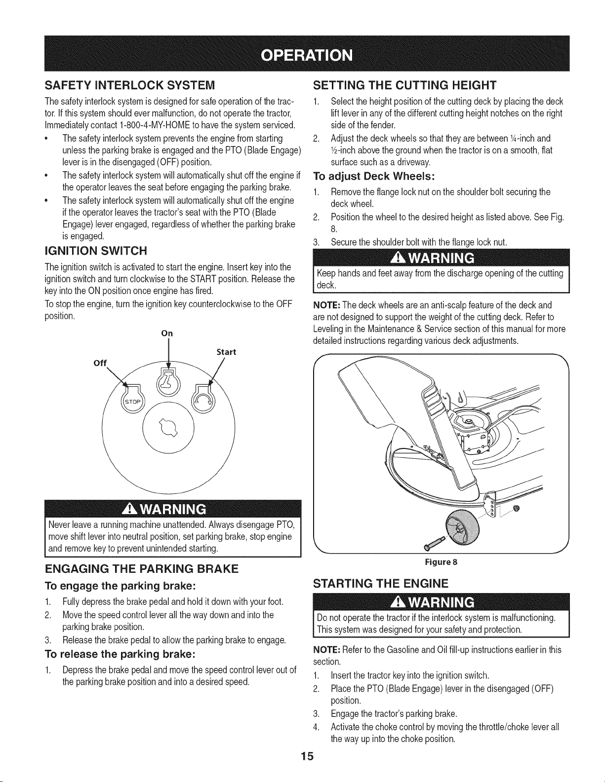
IGNITION SWITCH
Theignitionswitchis activatedto startthe engine,insertkey intothe
ignitionswitchand turnclockwiseto the STARTposition.Releasethe
keyintothe ON positiononce enginehas fired.
Tostopthe engine,turnthe ignitionkeycounterclockwiseto the OFF
position.
On
Start
off
Neverleavea runningmachineunattended.AlwaysdisengagePTO,
moveshift leverintoneutralposition,setparkingbrake,stopengine
andremovekeyto preventunintendedstarting.
ENGAGING THE PARKING BRAKE
To engage the parking brake:
1. Fullydepressthe brakepedaland holdit downwithyour foot.
2. Movethe speedcontrolleverall the way downandintothe
parkingbrakeposition.
3. Releasethe brakepedalto allow theparkingbraketo engage.
To release the parking brake:
1. Depressthe brakepedalandmovethe speedcontrolleverout of
the parkingbrakepositionandintoa desiredspeed.
SETTING THE CUTTING HEIGHT
1. Selectthe heightpositionof the cuttingdeckby placingthe deck
liftleverinanyof the differentcuttingheightnotcheson the right
sideof the fender.
2. Adjustthe deck wheelssothattheyarebetween1A-inchand
Y2-inchabovethe groundwhenthe tractoris on a smooth,fiat
surfacesuchas a driveway.
To adjust Deck Wheels:
1. Removethe flangelocknuton the shoulderbolt securingthe
deckwheel.
2. Positionthe wheelto thedesiredheightas listedabove.SeeFig.
8.
3. Securethe shoulderboltwiththe flangelocknut.
Keephandsandfeetawayfromthe dischargeopeningof the cutting
deck.
NOTE: Thedeckwheelsarean anti-scalpfeatureof the deckand
are notdesignedto supportthe weightof the cuttingdeck. Referto
Levelinginthe Maintenance& Servicesectionof thismanualfor more
detailedinstructionsregardingvariousdeckadjustments.
Figure8
STARTING THE ENGINE
Donot operatethe tractorif the interlocksystemis malfunctioning.
Thissystemwas designedfor yoursafetyand protection.
NOTE: Referto the GasolineandOil fill-up instructionsearlierin this
section.
1. Insertthe tractorkeyintothe ignitionswitch.
2. Placethe PTO(BladeEngage)leverin thedisengaged(OFF)
position.
3. Engagethe tractor'sparkingbrake.
4. Activatethechokecontrolby movingthethrottle/chokeleverall
the way upintothechoke position.
15
5. Turnthe ignitionkeyclockwiseto the STARTposition.Afterthe
enginestarts,releasethe key.It will returnto the ON (orNormal
Mowing)position.
Do NOTholdthe keyin the STARTpositionfor longer thanten
secondsat a time.Doingso maycausedamageto yourengine's
electricstarter.
6. Afterthe engine starts,deactivatethe chokecontroland placethe
throttlecontrolinthe FASTposition.
NOTE: Do NOTleavethechokecontrolonwhileoperatingthe tractor.
Doingso will resultina "rich" fuel mixtureandcausethe engineto run
poorly.
STOPPING THE ENGINE
If youstrikea foreignobject,stopthe engine,disconnectthe spark
plugwire(s)andgroundagainstthe engine.Thoroughlyinspectthe
machinefor anydamage.Repairthe damagebeforerestartingand
operating
1. Ifthe bladesareengaged,placethe PTO(BladeEngage)leverin
thedisengaged(OFF)position.
2. Turnthe ignitionkeycounterclockwiseto the STOPposition.
3. Removethe keyfromthe ignitionswitchto preventunintended
starting.
DRIVING THE TRACTOR
Avoidsuddenstarts,excessivespeedand suddenstops.
Donot leavethe seatof the tractorwithoutfirst placingthe PTO
(BladeEngage)leverin the disengaged(OFF)position,depressing
the brakepedalandengagingthe parkingbrake.If leavingthe tractor
unattended,also turnthe ignitionkeyoff andremovethe key.
Alwayslook downandbehindbeforeand while backingup to avoida
back-overaccident.
1. Depressthe brakepedalto releasethe parkingbrakeandthen let
the pedal up.
2. Movethethrottleleverintothe FAST(rabbit)position.
3. Placethe shift leverineitherthe FORWARDor REVERSE
position.
IMPORTANT: Do NOTuse the shiftleverto changethedirection
of travelwhenthe tractoris in motion.Alwaysusethe brakepedalto
bringthe tractorto a completestopbeforeshifting.
4. Graduallybeginto applypressureto the drivepedal.Thefurther
downthe pedalis pushed,thefasterthe tractorwilltravel inthe
desireddirectionbasedon the positionof the shift lever.
5. The lawntractoris broughtto a stopby releasingthedrive pedal
andthen depressingthe brakepedal.
Beforeleavingthe operator'spositionfor any reason,disengagethe
blades,placethe shift leverinneutral,engagethe parkingbrake,
shutengineoff and removethe key.
Whenstoppingthetractorfor any reasonwhileon a grasssurface,
always:
1. Placethe shift leverin neutral,
2. Engagethe parkingbrake,
3. Shutengineoff and removethe key.Doingso will minimizethe
possibilityof havingyour lawn"browned"byhot exhaustfrom
yourtractor'srunningengine.
16
DRiViNG ON SLOPES
Referto the SLOPEGAUGEin the SafetyInstructionssectionof the
manualto helpdetermineslopeswhereyou mayoperatethis tractor
safely.
Do notmowon inclineswitha slopein excessof 15degrees(a rise
of approximately2-1/2feet every10feet). Thetractorcouldoverturn
andcauseseriousinjury.
• Mow upand downslopes,NEVERacross.
Exerciseextremecautionwhenchangingdirectionon slopes.
Watchfor holes,ruts,bumps,rocks,or otherhiddenobjects.
Uneventerraincouldoverturnthemachine.Tallgrasscan hide
obstacles.
Avoidturnswhendrivingona slope.Ifa turn mustbemade,turn
downthe slope.Turningup a slopegreatlyincreasesthechance
of a roll over.
Avoidstoppingwhendrivingupa slope.Ifit is necessaryto stop
whiledrivingupa slope,start up smoothlyand carefullyto reduce
the possibilityof flippingthe tractoroverbackward.
ENGAGING THE BLADES
Engagingthe PTO(BladeEngage)transferspowerto the cuttingdeck
orother (separatelyavailable)attachments.Toengagethe blades,
proceedas follows:
1. Movethe throttle/chokecontrol leverto the FAST(rabbit)position.
2. Graspthe PTO(BladeEngage)leverandpivotit all the way
forwardintothe engaged(ON)position.
3. Keepthe throttleleverin the FAST(rabbit)positionforthe most
efficientuseof thecuttingdeckor other(separatelyavailable)
attachments.
NOTE: The enginewill automaticallyshutoff if the PTOis engaged
withthe shiftleverin positionfor reversetravelwiththe ignitionkey in
the ONposition.
MULCHING
A mulchkit is availableasan attachment.Mulchingis a processof
recirculatinggrassclippingsrepeatedlybeneaththe cuttingdeck.The
ultra-fineclippingsare thenforcedback intothe lawnwherethey act as
a naturalfertilizer.
A mulchkit canbe purchasedthroughthe retaillocationinwhich you
purchasedthis tractor.For more information, simply contact Sears
at 1-800-4-MY-HOME®.
USING THE DECK LIFT LEVER
Toraisethe cuttingdeck,movethe decklift levertothe left,then place
it in the notchbestsuitedfor yourapplication.Referto SettingThe
CuttingHeightearlierinthis section.
MOWING
Tohelpavoidbladecontactora thrownobjectinjury,keepbystand-
ers,helpers,childrenand petsat least75 feetfrom the machine
while it is in operation.Stopmachineif anyoneentersthe area.
The followinginformationwill be helpfulwhenusingthe cuttingdeck
withyourtractor:
Planyourmowingpatternto avoiddischargeof materialstoward
roads,sidewalks,bystandersandthe like.Also,avoiddischarging
materialagainstawall or obstructionwhichmaycausedischarged
materialto ricochetbacktowardthe operator.
Donot mowat highgroundspeed,especiallyif a mulchkit or
grasscollectoris installed.
• Forbest resultsit is recommendedthat the first twolaps becut
withthe dischargethrowntowardsthe center.After the firsttwo
laps,reversethedirectionto throwthe dischargeto theoutside
for the balanceof cutting.Thiswill givea betterappearanceto the
lawn.
• Donot cutthe grasstoo short. Shortgrassinvitesweedgrowth
andyellowsquicklyin dry weather.
• Mowingshouldalwaysbe donewith the engineat full throttle.
• Underheavierconditionsit maybe necessaryto go backoverthe
cut areaa secondtimeto get a cleancut.
• Do NOTattemptto mowheavybrushandweeds andextremely
tall grass.Yourtractoris designedto mowlawns,NOTclear
brush.
• Keepthe bladessharpand replacethe bladeswhenworn. Refer
to CuttingBladesinthe Servicesectionof thismanualfor proper
bladesharpeninginstructions.
HEADLIGHTS
• The lampsare ONwheneverthe tractor'sengineis running.
• The lampsturn OFFwhenthe ignitionkeyis movedto the STOP
position.
17
MAINTENANCE SCHEDULE
Beforeperforminganytypeof maintenance/service,disengageall
controlsand stoptheengine.Waituntilallmovingpartshavecometo
acompletestop.Disconnectsparkplugwireandgrounditagainstthe
enginetopreventunintendedstarting.Alwayswearsafetyglassesduring
operationor whileperforminganyadjustmentsor repairs.
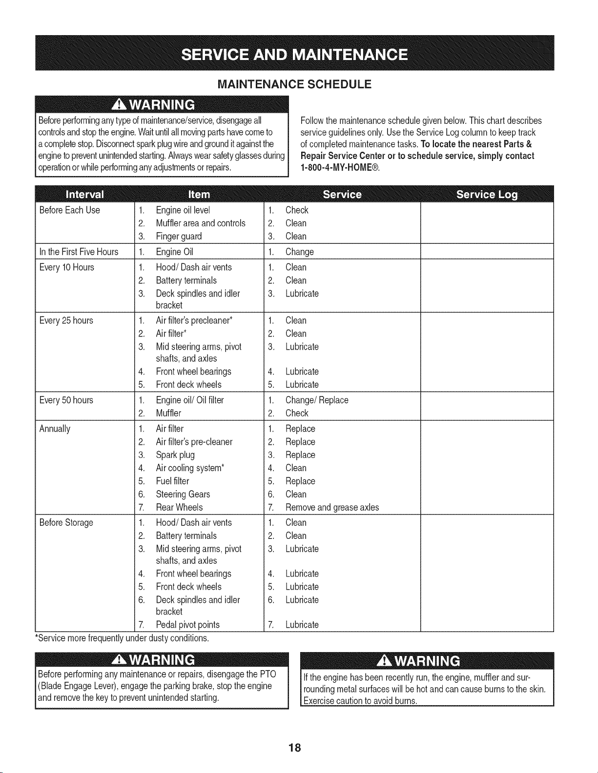
Followthe maintenanceschedulegivenbelow.Thischartdescribes
serviceguidelinesonly.Usethe ServiceLogcolumnto keeptrack
of completedmaintenancetasks.To locate the nearest Parts &
Repair Service Centeror to scheduleservice,simplycontact
1-800-4-MY-HOME®.
BeforeEachUse
In the FirstFiveHours
Every10Hours
Every25 hours
Every50 hours
Annually
BeforeStorage
1. Engineoil level
2. Mufflerareaand controls
3. Fingerguard
1. EngineOil
1. Hood/Dashair vents
2. Batteryterminals
3. Deckspindlesand idler
bracket
1. Air filter'sprecleaner*
2. Air filter*
3. Midsteeringarms,pivot
shafts,andaxles
4. Frontwheelbearings
5. Frontdeckwheels
1. Engineoil/Oil filter
2. Muffler
1. Air filter
2. Air filter'spre-cleaner
3. Sparkplug
4. Air coolingsystem*
5. Fuelfilter
6. SteeringGears
7. RearWheels
1. Hood/Dashair vents
2. Batteryterminals
3. Midsteeringarms,pivot
shafts,andaxles
4. Frontwheelbearings
5. Frontdeckwheels
6. Deckspindlesand idler
bracket
7. Pedalpivotpoints
1. Check
2. Clean
3. Clean
1. Change
1. Clean
2. Clean
3. Lubricate
1. Clean
2. Clean
3. Lubricate
4. Lubricate
5. Lubricate
1. Change/Replace
2. Check
1. Replace
2. Replace
3. Replace
4. Clean
5. Replace
6. Clean
7. Removeandgreaseaxles
1. Clean
2. Clean
3. Lubricate
4. Lubricate
5. Lubricate
6. Lubricate
7. Lubricate
*Servicemorefrequentlyunderdustyconditions.
Beforeperformingany maintenanceor repairs,disengagethe PTO
(BladeEngageLever),engagethe parkingbrake,stopthe engine
and removethe keyto preventunintendedstarting.
Ifthe enginehasbeen recentlyrun,the engine,mufflerandsur-
roundingmetalsurfaceswill behotand cancause burnsto the skin.
Exercisecautionto avoidburns.
18
ENGINE MAINTENANCE
Checking the Engine Oil
Onlyuse highqualitydetergentoil ratedwithAPIserviceclassification
SF,SG,SH,or SJ, Selectthe oil's SAEviscositygradeaccordingto
the expectedoperatingtemperature.Followthe chartbelow.
Althoughmulti-viscosityoils (5W20,10W30,etc.)improvestarting
in coldweather,theywill resultinincreasedoil consumptionwhen
usedabove32°E Checkyour engineoillevelmorefrequentlyto avoid
possibleenginedamagefromrunninglowonoil.
('_older _ 32°F _War me'_r
Oil Viscosity Chart
Tocheckthe engineoil, proceedas follows:
• Ensurethat the tractoris ona levelsurface.
• Cleantheoil fill areaof anydebris.
1. Removethedipstickandwipe withaclean cloth.
2. Insertandtightendipstick.
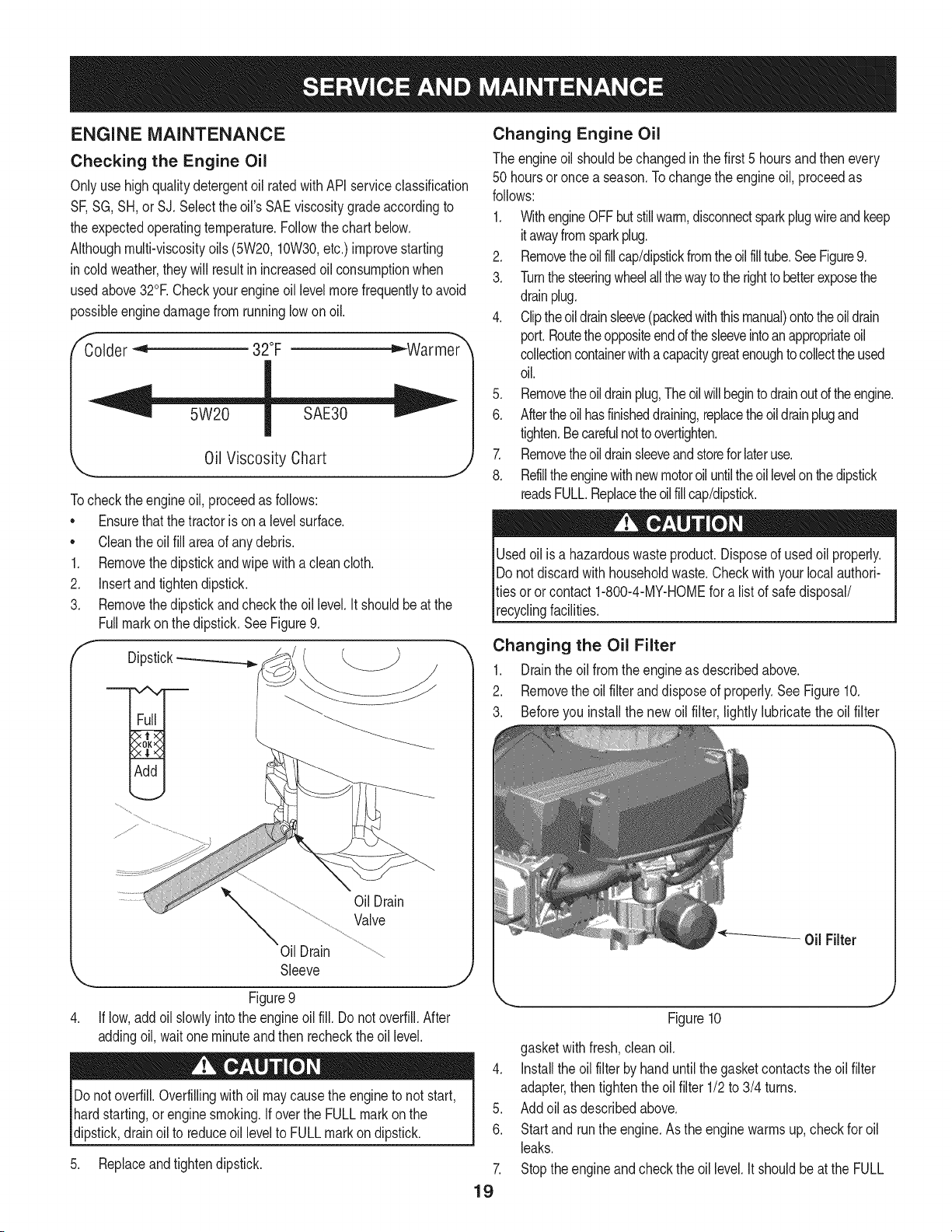
3. Removethedipstickandcheckthe oil level.It shouldbeat the
Fullmarkonthe dipstick.SeeFigure9.
f
Dipstick-_
OilDrain
Valve
Oil Drain
Sleeve
J
Figure9
If low,addoil slowlyintothe engineoilfill. Do notoverfill.After
addingoil, wait oneminuteand then recheckthe oil level.
Donotoverfill.Overfillingwithoil maycausethe engineto not start,
hardstarting,or enginesmoking.If overthe FULLmarkon the
dipstick,drainoil to reduceoil levelto FULLmarkon dipstick.
5. Replaceandtightendipstick.
Changing Engine Oil
The engineoil shouldbe changedinthe first 5 hoursand thenevery
50 hoursoronce a season.Tochangethe engineoil, proceedas
follows:
1. WithengineOFFbutstillwarm,disconnectsparkplugwireandkeep
itawayfromsparkplug.
2. Removetheoil fillcap/dipstickfromtheoil filltube.SeeFigure9.
3. Turnthesteeringwheelallthewaytothe rightto betterexposethe
drainplug.
4. Cliptheoildrainsleeve(packedwiththismanual)ontotheoildrain
port.Routetheoppositeendof thesleeveintoan appropriateoil
collectioncontainerwithacapacitygreatenoughto collecttheused
oil.
5. Removetheoil drainplug,Theoilwillbeginto drainoutof theengine.
6. Aftertheoilhasfinisheddraining,replacetheoil drainplugand
tighten.Becarefulnottoovertighten.
7. Removetheoil drainsleeveandstoreforlateruse.
8. Refilltheenginewithnewmotoroiluntiltheoillevelonthedipstick
readsFULL.Replacetheoilfillcap/dipstick.
Usedoil is a hazardouswasteproduct.Disposeof usedoil properly.
Do notdiscardwithhouseholdwaste.Checkwith your localauthori-
ties oror contact1-800-4-MY-HOMEfor alist of safedisposal/
recyclingfacilities.
Changing the Oil Filter
1. Drainthe oil fromthe engineas describedabove.
2. Removethe oil filterand disposeof properly.See Figure10.
3. Beforeyou installthe newoil filter, lightlylubricatethe oil filter
Figure10
gasketwithfresh,cleanoil.
4. Installthe oil filter byhanduntilthe gasketcontactstheoil filter
adapter,then tightenthe oilfilter 1/2to 3/4 turns.
5. Addoil as describedabove.
6. Startand runthe engine.Asthe enginewarmsup,checkfor oil
leaks.
7. Stoptheengineandcheckthe oil level.It shouldbeat the FULL
19
markon the dipstick.
Fuel Filter
31osioncan causesevereburnsor death.
Air Cleaner
Iffilters,or coversare notinstalledcorrectlyseriousinjuryor death
could resultfrom backfire.Do notattemptto startthe enginewith
themremoved.
• Keepgasolineawayfrom sparks,openflames,pilotlights,heat,
andotherignitionsources.
• Checkfuel lines,tank,cap,and fittingsfrequentlyforcracksor
leaks.Replaceif necessary.
• Beforereplacingthe fuelfilter,drainthe fueltankas perthe
instructionsbelow.
• Do notdrainfuel whenthe engineis hot.Allowthe engine
adequatetimeto cool. Drainfuel intoan approvedcontainer
outdoors,awayfromopenflame.
• Drainanylargevolumeof fuelfrom the tank by disconnectingthe
fuel linefromthe in-linefuelfilter neartheengine.
• Removethe fuel line fromthe In-lineside (sidetowardsthe fuel
tank)of thefuel filter.
• Replacementpartsmustbethe sameand installedin the same
positionas theoriginalparts.
• Iffuel spills,waituntil it evaporatesbeforestartingengine.
• Beforereplacingthe fuelfilter,drainthe fueltank. Otherwisefuel
can leakout andcausea fireor explosion.
To Drainthe fuel:
1. Locatethefuelfilter,whichis routedonthe leftsideofthe eng=ne
betweenthe fueltankand the carburetor,andmaybeattachedto
theenginewitha tie strap.Cutthetie strap,if present,then pinch
thein-lineclamponthefuelfilterwitha pairof pliers,slidethe
clampupthefuelline.Pullthe fuellinefreefromthefilterandplace
theopenendof the lineintoanapprovedcontainerto drainthefuel.
Tochangethe fuel filter:
1. Usepliersto squeezethe tabs onthe otherclamp(theout-line
sideof the fuel filter),thenslidethe clamp awayfromthe fuel filter.
Twistandpull the fuellineoff of the fuelfilter.See Figure11.
2. Checkthe fuel linesfor cracksor leaks.Replaceif necessary.
3. Replacethe fuel filterwithan originalequipmentreplacement
filter.Call1-800-4-MY-HOME®to purchasethe originalequip-
mentreplacementfilter.
4. Securethe fuel lineswith the clamps.
f
Donot use pressurizedair or solventsto cleanthe air cleaner
cartridge.
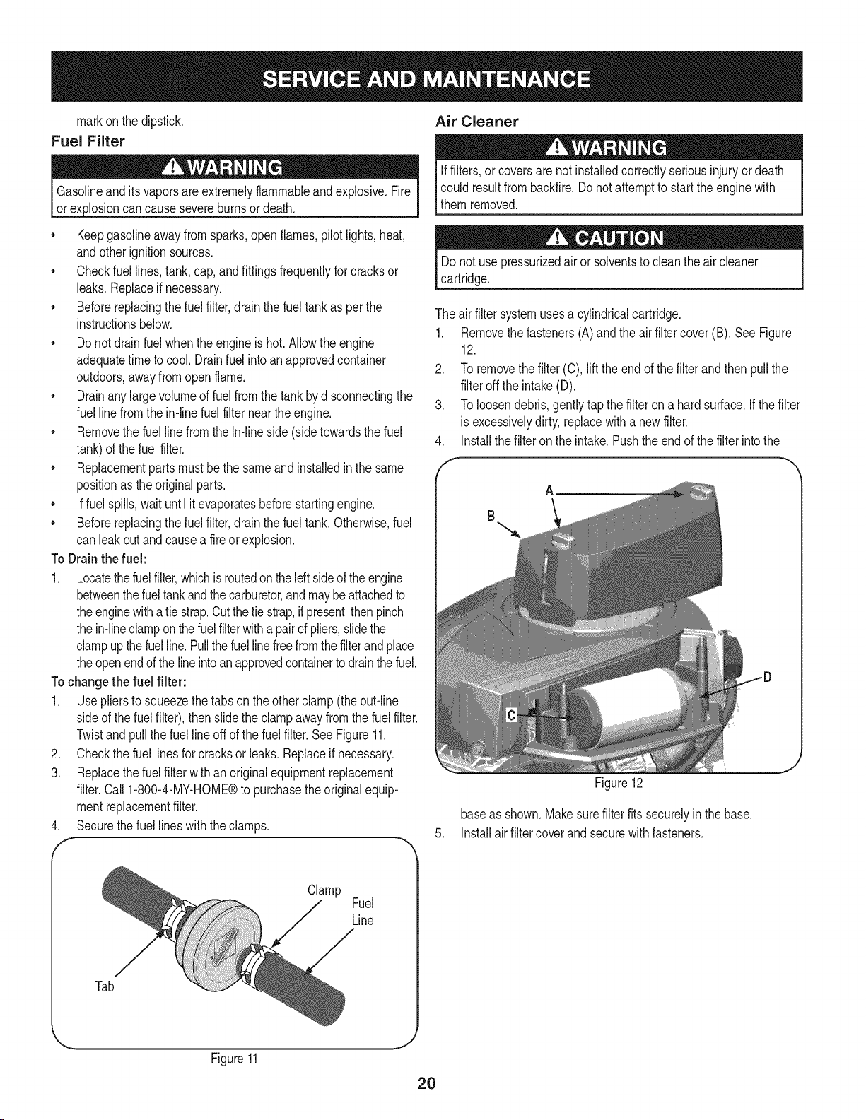
The airfiltersystemuses a cylindricalcartridge.
1. Removethe fasteners(A)andthe airfilter cover(B). SeeFigure
12.
2. To removethe filter(C), liftthe end of the filterandthen pullthe
filteroff the intake(D).
3. To loosendebris,gently tapthe filter on a hardsurface,if thefilter
is excessivelydirty,replacewitha newfilter.
4. installthe filteronthe intake.Pushthe endof the filter intothe
f -,
Figure12
baseas shown.Makesurefilterfits securelyin the base.
5. installair filtercover andsecurewith fasteners.
Clamp
Fuel
Line
Tab
... J
Figure11
2O
Spark Plug
1. Cleanareaaroundthe spark plugbase.Do notsandblastspark
plug,Sparkplugshouldbecleanedby scrapingorwire brushing
andwashingwitha commercialsolvent
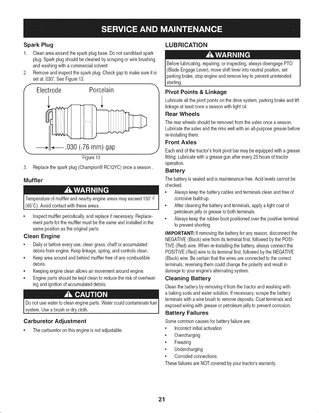
Removeandinspectthe spark plug.Checkgap to makesureit is
setat .030".See Figure13.
Electrode Porcelain
_.030 (.76 mm) gap
\
Figure13
3. Replacethesparkplug (Champion®RC12YC)once a season.
Muffler
Temperatureof mufflerand nearbyengineareasmayexceed150° F
(65°0).Avoidcontactwith theseareas.
• inspectmufflerperiodically,and replaceif necessary.Replace-
mentpartsfor the mufflermustbethe sameand installedin the
samepositionas the originalparts.
Clean Engine
• Dailyor beforeeveryuse,cleangrass,chaff oraccumulated
debrisfromengine.Keeplinkage,spring,andcontrolsclean.
Keepareaaroundand behindmufflerfreeof any combustible
debris.
Keepingenginecleanallowsair movementaroundengine.
• Enginepartsshouldbe keptcleanto reducethe riskof overheat-
ingandignitionof accumulateddebris.
Do notuse waterto cleanengineparts.Watercouldcontaminatefuel
system.Usea brushor dry cloth.
Carburetor Adjustment
• Thecarburetoron thisengineisnot adjustable.
LUBRICATION
Beforelubricating,repairing,or inspecting,alwaysdisengagePTO
(BladeEngageLever),moveshift leverinto neutralposition,set
parkingbrake,stopengineand removekey to preventunintended
starting.
Pivot Points & Linkage
Lubricateall the pivotpointsonthe drivesystem,parkingbrakeand lift
linkageat leastonce a seasonwith lightoil.
Rear Wheels
The rearwheelsshouldberemovedfromtheaxlesoncea season.
Lubricatetheaxlesand the rims wellwithan all-purposegreasebefore
re-installingthem.
Front Axles
Eachend of thetractor'sfront pivotbar maybeequippedwith a grease
fitting.Lubricatewitha greasegunafterevery25hoursof tractor
operation.
Battery
The batteryis sealedandis maintenance-free.Acidlevelscannotbe
checked.
Alwayskeepthe batterycablesandterminalscleanandfree of
corrosivebuild-up.
Aftercleaningthe batteryandterminals,applya lightcoatof
petroleumjelly orgreaseto bothterminals.
Alwayskeepthe rubberbootpositionedoverthe positiveterminal
to preventshorting.
iMPORTANT: if removingthe batteryfor any reason,disconnectthe
NEGATIVE(Black)wirefrom itsterminalfirst, followedby the POSI-
TIVE(Red)wire.When re-installingthe battery,alwaysconnectthe
POSITIVE(Red)wire to its terminalfirst, followedbythe NEGATIVE
(Black)wire.Becertainthatthe wiresareconnectedto the correct
terminals;reversingthemcouldchangethe polarityandresultin
damageto yourengine'salternatingsystem.
Cleaning Battery
Cleanthe batteryby removingit fromthe tractorandwashingwith
a bakingsodaandwatersolution.If necessary,scrapethe battery
terminalswitha wirebrushto removedeposits.Coatterminalsand
exposedwiringwithgreaseor petroleumjellyto preventcorrosion.
Battery Failures
Somecommoncausesfor batteryfailureare:
incorrectinitialactivation
Overcharging
Freezing
Undercharging
Corrodedconnections
Thesefailuresare NOTcoveredbyyourtractor'swarranty.
21
CLEANING THE ENGINE AND DECK
Anyfuel oroil spilledonthe machineshouldbe wipedoff promptly.Do
NOTallowdebristo accumulatearoundthe coolingfinsof the engine
oron anyother partof the machine.
IMPORTANT: The useof a pressurewasherto cleanyourtractoris
NOTrecommended.It maycausedamageto electricalcomponents,
spindles,pulleys,bearingsor the engine.
A screwplugcan befoundon yourtractor'sdecksurfaceas seenin
Fig. 14.Thisplugcanbe replacedwith a waterport to beusedas part
of a separately-availabledeck washsystem.
The DeckWash SystemTM is usedto rinsegrassclippingsfrom the
deck'sundersideandpreventthe buildupof corrosivechemicals.
NOTE: Adeck washsystemcan bepurchasedthroughthe retail
locationinwhich youpurchasedthis tractor.For moreinformation,call
1-800-4-MY-HOME®.
/
/
Figure14
ADJUSTMENTS
Neverattemptto makeanyadjustmentswhilethe engineis running,
exceptwherespecifiedin the operator'smanual.
Leveling the Deck
NOTE: Checkthe tractor'stire pressurebeforeperforminganydeck
levelingadjustments.Referto Tiresin the Servicesectionof this
manualfor moreinformationregardingtire pressure.
Front To Rear
Thefrontof the cuttingdeckis supportedby a stabilizerbarthatcan
beadjustedto levelthe deckfromfront to rear.Thefront of the deck
shouldbebetween1A-inchand 3A-inchlowerthan the rearof thedeck.
Adjustif necessaryas follows:
1. Withthe tractorparkedon a firm,levelsurface,placethe lever
for liftingthe platformon the secondto thetop notch(second
highestposition)androtatethe bladeas closeas possibleto the
dischargechannelthat is parallelto thetractor.
2. Measurethedistancefromthe frontof the bladetip to the ground
andthe rearof the bladetip to theground.Thefirst measure-
menttakenshouldbe between1A"and 3A"lessthanthe second
measurement.Determinethe approximatedistancenecessaryfor
properadjustmentand proceed,if necessary,to the nextstep.
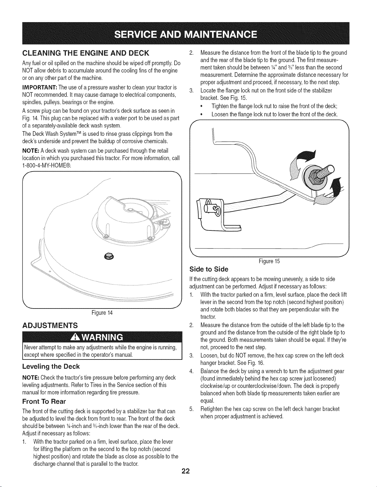
3. Locatethe flangelocknut onthe frontsideof the stabilizer
bracket.SeeFig. 15.
• Tightenthe flangelocknut to raisethe frontof the deck;
Loosentheflange locknutto lowerthefrontof thedeck.
o
f
/
Figure15
Side to Side
Ifthe cuttingdeckappearsto be mowingunevenly,a sideto side
adjustmentcan beperformed.Adjustif necessaryas follows:
1. Withthe tractorparkedona firm, levelsurface,placethe deck lift
leverin the secondfromthe top notch(secondhighestposition)
and rotatebothbladessothat theyare perpendicularwiththe
tractor.
2. Measurethedistancefromthe outsideof the left bladetip to the
groundandthe distancefrom the outsideof the rightblade tip to
the ground.Bothmeasurementstaken shouldbeequal.If they're
not, proceedto the nextstep.
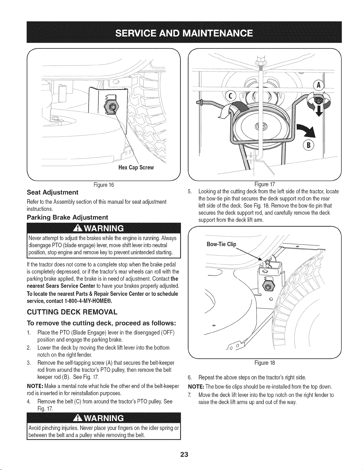
3. Loosen,but do NOTremove,the hexcap screwon the leftdeck
hangerbracket.SeeFig. 16.
4. Balancethedeckby usinga wrenchto turn theadjustmentgear
(foundimmediatelybehindthehex cap screwjust loosened)
clockwise/uporcounterclockwise/down.Thedeckis properly
balancedwhen bothbladetip measurementstakenearlierare
equal.
5. Retightenthe hex cap screwon the left deck hangerbracket
when properadjustmentis achieved.
22
He× Cap Screw
'_. ._
Figure16
Seat Adjustment
Referto the Assemblysectionof this manualfor seatadjustment
instructions.
Parking Brake Adjustment
Neverattemptto adjustthe brakeswhiletheengineis running.Always
disengagePTO(bladeengage)lever,moveshiftleverintoneutral
position,stopengineandremovekeyto preventunintendedstarting.
If thetractordoes notcometo acompletestopwhenthe brakepedal
is completelydepressed,or if the tractor'srearwheelscan rollwiththe
parkingbrakeapplied,the brakeis in needof adjustment.Contactthe
nearest Sears Service Center to haveyourbrakesproperlyadjusted.
Tolocatethe nearest Parts& Repair ServiceCenter or to schedule
service,contact 1-800-4-MY-HOME®.
CUTTING DECK REMOVAL
To remove the cutting deck, proceed as follows:
1. Placethe PTO(Blade Engage)leverin the disengaged(OFF)
positionand engagethe parkingbrake.
2. Lowerthe deck by movingthe deck lift lever intothe bottom
notchon the rightfender.
3. Removetheself-tappingscrew(A) that securesthe belt-keeper
rodfromaroundthe tractor'sPTOpulley,thenremovethe belt
keeperrod(B). SeeFig. 17.
NOTE: Makea mentalnotewhatholethe otherendof the belt-keeper
rodisinsertedin for reinstallationpurposes.
4. Removethebelt (C) from aroundthetractor'sPTOpulley.See
Fig.17.
F
,J
Figure17
Lookingat thecuttingdeckfrom the left side of the tractor,locate
the bow-tiepin that securesthedecksupportrodonthe rear
Idt sideof the deck. SeeFig. 18.Removethe bow-tiepin that
securesthedecksupportrod,andcarefullyremovethe deck
supportfromthe deck lift arm.
J
Figure18
6. Repeatthe abovestepson the tractor'srightside.
NOTE: The bow-tieclipsshouldbe re-installedfrom the top down.
7. Movethe decklift leverintothe top notchon the rightfenderto
raisethe decklift arms upand out of the way.
Avoidpinchinginjuries.Neverplaceyourfingers onthe idlerspringor
betweenthe belt anda pulleywhile removingthe belt.
23
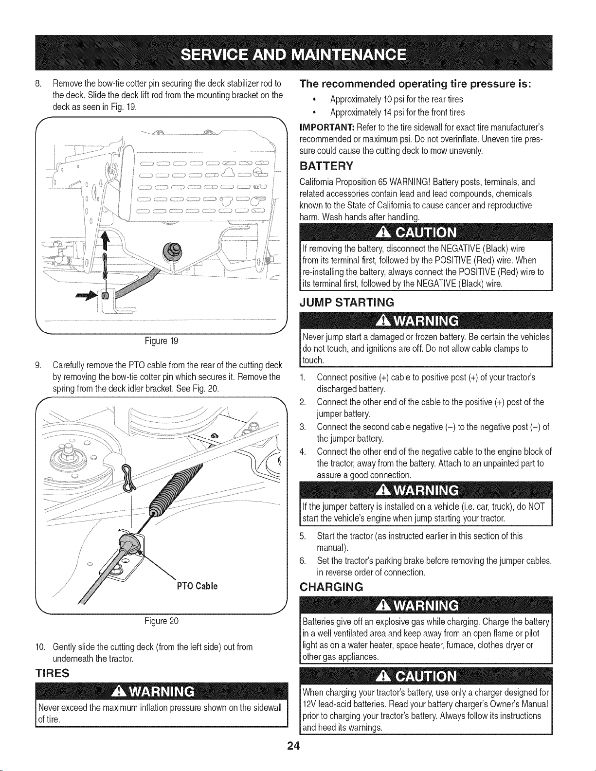
8, Removethe bow-tiecotterpin securingthe deckstabilizerrod to
thedeck. Slidethe decklift rodfromthe mountingbracketon the
deckasseen in Fig. 19.
............./1;_,_......................... / ..............................
_... j2
Figure19
.
f
Carefullyremovethe PTOcablefrom the rearof the cuttingdeck
by removingthe bow-tiecotterpinwhich securesit. Removethe
springfromthe deckidlerbracket.SeeFig.20.
PTOCable
Figure20
10. Gentlyslidethe cuttingdeck(fromthe left side)out from
underneaththe tractor.
TIRES
Neverexceedthe maximuminflationpressureshownonthe sidewall
of tire.
The recommended operating tire pressure is:
• Approximately10psi for the reartires
• Approximately14psi for the fronttires
IMPORTANT: Referto the tire sidewaNfor exacttire manufacturer's
recommendedor maximumpsi.Donot overinflate.Uneventire pres-
surecould causethe cuttingdeckto mowunevenly.
BATTERY
CaliforniaProposition65 WARNING!Batteryposts,terminals,and
relatedaccessoriescontainleadandleadcompounds,chemicals
knownto the Stateof Californiato causecancer andreproductive
harm.Washhandsafter handling.
If removingthe battery,disconnectthe NEGATIVE(Black)wire
fromits terminalfirst,followedbythe POSITIVE(Red) wire.When
relinstallingthe battery,alwaysconnectthe POSITIVE(Red)wire to
I ts termna f rst,fo owedby the NEGATVE (Back) w re.
JUMP STARTING
Neverjump starta damagedor frozenbattery.Becertain thevehicles
do not touch,and ignitionsareoff. Do notallowcable clampsto
touch.
1. Connectpositive(+)cableto positivepost (+)of yourtractor's
dischargedbattery.
2. Connecttheotherendof thecableto the positive(+)post of the
jumperbattery.
3. Connectthesecondcable negative(-) to the negativepost(-) of
the jumperbattery.
4. Connecttheotherendof thenegativecableto the engineblockof
the tractor,awayfromthe battery.Attachto anunpaintedpartto
assurea goodconnection.
Ifthejumper batteryis installedona vehicle(i.e.car,truck),do NOT
startthe vehicle'senginewhenjump startingyourtractor.
5. Startthe tractor(as instructedearlierin this sectionof this
manual).
6. Set the tractor'sparkingbrakebeforeremovingthejumpercables,
in reverseorderof connection.
CHARGING
give offan explosivegas whilecharging.Chargethe batteryI
Batteries
ina wellventilatedareaand keepawayfroman openflame or pilot
ght as ona waterheater,spaceheater,furnace,c othesdryeror |
othergas appliances.
J
Whenchargingyourtractor'sbattery,useonlya chargerdesignedfor I
12Vlead-acidbatteries.Readyourbatterychargers Owners Manual
priorto chargingyourtractors battery.Alwaysfollowits instructions I
land heed ts warnngs. j
24
If yourtractorhasnot beenputinto usefor an extendedperiodof time,
chargethe batteryas follows:
1. Setyour batterychargerto delivera max of 10amperes.
If yourbatterychargeris automatic,chargethe batteryuntilthe
chargerindicatesthat chargingis complete.Ifthe chargeris not
automatic,chargefor nofewerthaneight hours.
FUSE
One20 AMPfuseis installedin yourtractor'swiringharnessto protect
the tractor'selectricalsystemfrom damagecausedbyexcessive
amperage.
If theelectricalsystemdoesnot function,or yourtractor'senginewill
not crank,first checkto be certainthat the fuse hasnot blown.It can
befoundat the rearof the unit,underneaththefenderlocatedby the
battery.
Alwaysusea fusewiththe sameamperagecapacityfor replacement.
CUTTING BLADES
Shutthe engineoff and removeignitionkey beforeremovingthe
cuttingblade(s)for sharpeningor replacement.Protectyourhands
by usingheavygloveswhengraspingthe blade.
Periodicallyinspectthe bladeand/or spindlefor cracksordamage,
especiallyafter you'vestrucka foreignobject. Donot operatethe
machineuntil damagedcomponentsare replaced.
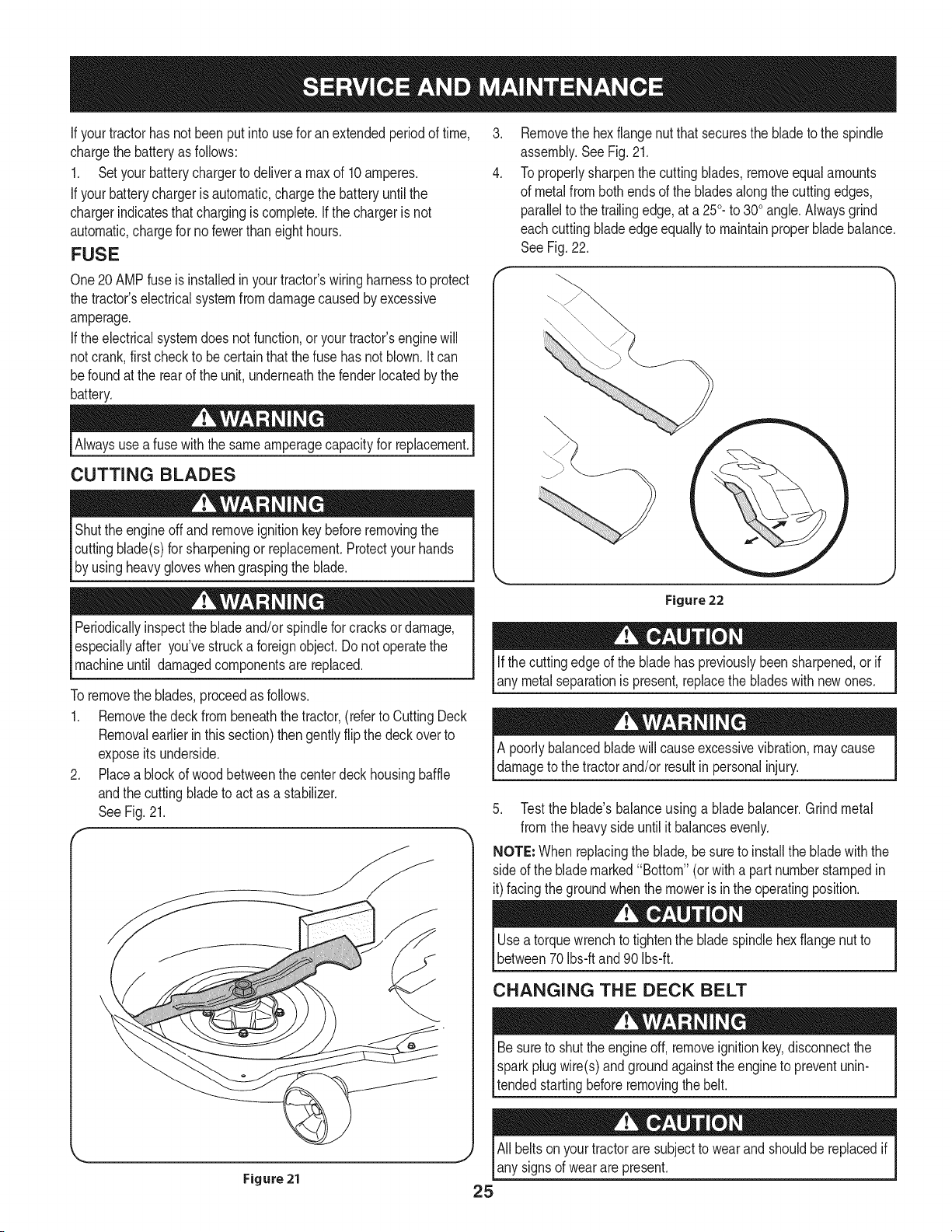
Toremovethe blades,proceedas follows.
1. Removethedeckfrombeneaththe tractor,(referto CuttingDeck
Removalearlierinthis section)thengently flip thedeck overto
exposeitsunderside.
2. Placea blockof woodbetweenthe centerdeckhousingbaffle
andthe cuttingbladeto actas a stabilizer.
SeeFig. 21.
f
.
4.
Removethe hexflangenut that securesthe bladeto the spindle
assembly.SeeFig.21.
To properlysharpenthe cuttingblades,removeequalamounts
of metalfrombothendsof the bladesalongthe cuttingedges,
parallelto the trailingedge,at a 250.to 300angle.Alwaysgrind
eachcutting bladeedgeequallyto maintainproperbladebalance.
SeeFig.22.
Figure 22
Ifthe cuttingedgeof the bladehas previouslybeen sharpened,or if
any metalseparationis present,replacethe bladeswith newones.
A poorlybalancedbladewill causeexcessivevibration,maycause
damageto the tractorand/or resultin personalinjury.
5. Testthe blade'sbalanceusinga bladebalancer.Grind metal
from the heavyside untilit balancesevenly.
NOTE: Whenreplacingthe blade,be sureto installthe blade withthe
sideof the blademarked"Bottom" (orwith a part numberstampedin
it)facingthe groundwhenthe moweris inthe operatingposition.
Usea torquewrenchto tightenthe bladespindlehexflangenut to
between70Ibs-ftand 90 Ibs-ft.
CHANGING THE DECK BELT
Besureto shutthe engineoff, removeignitionkey,disconnectthe
Isparkplugwire(s)andgroundagainstthe engineto preventunin-
ltended startingbeforeremovingthe belt.
All beltsonyourtractoraresubjectto wearandshouldbereplacedif
any signsof wearare present.
iMPORTANT: The V-beltfoundon yourtractoris speciallydesigned
to engageanddisengagesafely.A substitute(non-OEM)V-beltcan
bedangerousby notdisengagingcompletely.Fora properworking
machine,useidenticalequipmentbeltsas listedin the parts pagesof
thisOperator'sManual.
Tochangeor replacethe deckbelt onyourtractor,proceedas follows:
1. Removethe deckas instructedearlier inthis section.
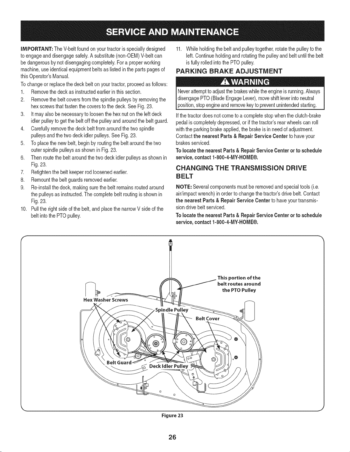
2. Removethe beltcoversfromthe spindlepulleysby removingthe
hexscrewsthatfastenthecoversto the deck.SeeFig.23.
3. it mayalso benecessaryto loosenthe hex nuton the leftdeck
idlerpulleyto getthe belt off the pulleyand aroundthe beltguard.
4. Carefullyremovethe deck beltfromaroundthe twospindle
pulleysandthetwo deck idlerpulleys,SeeFig,23,
5. Toplacethe newbelt,begin by routingthe belt aroundthe two
outerspindlepulleysas shownin Fig,23,
6. Thenroutethe beltaroundthe twodeckidlerpulleysas shownin
Fig.23,
7. Retightenthe belt keeperrodloosenedearlier.
8. Remountthebelt guardsremovedearlier,
9. Re-installthedeck, makingsurethe belt remainsroutedaround
the pulleysas instructed.Thecompletebelt routingisshownin
Fig,23.
10. Pullthe rightside ofthe belt,and placethe narrowVside of the
belt intothe PTOpulley.
11. Whileholdingthe belt and pulleytogether,rotatethe pulleyto the
left. Continueholdingand rotatingthe pulleyand belt untilthe belt
is fullyrolledinto the PTOpulley.
PARKING BRAKE ADJUSTMENT
Neverattemptto adjustthe brakeswhiletheengineis running.Always
disengagePTO(BladeEngageLever),moveshiftleverintoneutral
position,stopengineandremovekeyto preventunintendedstarting.
Ifthe tractordoesnot cometo a completestopwhenthe clutch-brake
pedalis completelydepressed,or if the tractor'srearwheelscan roll
withthe parkingbrakeapplied,the brakeis inneedof adjustment.
Contactthe nearest Parts& RepairService Centerto haveyour
brakesserviced.
Tolocatethe nearestParts& RepairServiceCenteror to schedule
service,contact1-800-4-MY-HOME®.
CHANGING THE TRANSMiSSiON DRIVE
BELT
NOTE: Severalcomponentsmust beremovedandspecialtools(i.e.
air/impactwrench)inorder to changethetractor'sdrivebelt. Contact
the nearest Parts& Repair Service Center to haveyourtransmis-
sion drivebelt serviced.
Tolocatethe nearestParts& RepairServiceCenteror to schedule
service, contact 1-800-4-MY-HOME®.
Hex Washer Screws
This portion of the
belt routes around
the PTO Pulley
Belt Cover
Belt Guard
_ _oo Deckidier Pulley
Figure 23
26
Neverstorelawntractorwithfuel intankindoorsorin poorly
ventilatedareaswherefuel fumesmayreachan openflame,spark,
orpilot lightas ona furnace,water heater,clothesdryer,or gas
appliance.
PREPARING THE ENGINE
IMPORTANT:Fuelleft in thefuel tank duringwarmweatherdeterio-
ratesandwill causeseriousstartingproblems.
To preventgumdepositsfromforminginsidethe engine'scarburetor
andcausingpossiblemalfunctionof theengine,thefuel systemmust
be eithercompletelyemptied,orthe gasolinemustbe treatedwitha
stabilizerto preventdeterioration.
1. Ifusingafuel stabilizer:
a. Readthe productmanufacturer'sinstructionsandrecom-
mendations.
b. Addto clean,freshgasolinethe correctamountof stabilizer
for the capacityof the fuel system.
c. Fillthe fueltankwith treatedfuel andrunthe enginefor 2-3
minutesto get stabilizedfuel intothe carburetor.
2. Ifemptyingthe fuel system:
a. Donot drainfuel whenthe engineis hot.Allowthe engine
adequatetimeto cool.Drainfuelinto anapprovedcontainer
outdoors,awayfromopenflame.
b. Drainany largevolumeof fuel fromthetank bydisconnect-
ing thefuel linefrom the in-linefuel filternearthe engine.
Seethe completeinstructionsfor DrainingThe Fuellaterin
this section.
Gasolineis extremelyflammableand can be explosiveundercertain
conditions.Draingasolinebeforestoringthe equipmentfor extended
periods.Drainfuel only intoan approvedcontaineroutdoors,away
froman openflame.Allowengineto cool.Extinguishcigarettes,
cigars,pipes,andothersourcesof ignitionpriorto drainingfuel.
Storegasolineinan approvedcontainerin safelocation.
c. Reconnectthe fuel lineand runthe engineuntil it startsto
falter,thenuse thechoketo keeptheenginerunninguntilall
fuel in thecarburetorhas beenexhausted.
d. Disconnectthefuel lineanddrainany remaininggasoline
fromthe system.
DRAiNiNG THE FUEL
1. Locatethe fuel filter,which is locatedonthe leftsideof the
engine,andmaybe attachedto the enginewith a tie strap.
2. Cutthe tie strap,if present,then pinchthe in-lineclamponthe
fuel filterwitha pair of pliers,slidethe clampupthe fuel line.
3. Pullthe fuel linefreefrom the filterandplacethe openendof the
lineintoanapprovedcontainerto drainthe fuel.
PREPARING THE LAWN TRACTOR
1. Cleanandlubricatetractorthoroughlyas describedin the lubrica-
tion instructions.
2. Donot usea pressurewasheror gardenhoseto cleanyour unit.
3. Storemowerin a dry,cleanarea. Do notstorenextto corrosive
materials,suchas fertilizer.
Gasolineis a toxicsubstance.Disposeof gasolineproperly.Contact
your localauthoritiesfor approveddisposalmethods.
3. Removethe sparkplug andpour one(1) ounceof engineoil
throughthe sparkplug holeintothe cylinder.Cranktheengine
severaltimesto distributethe oil. Replacethe sparkplug.
27
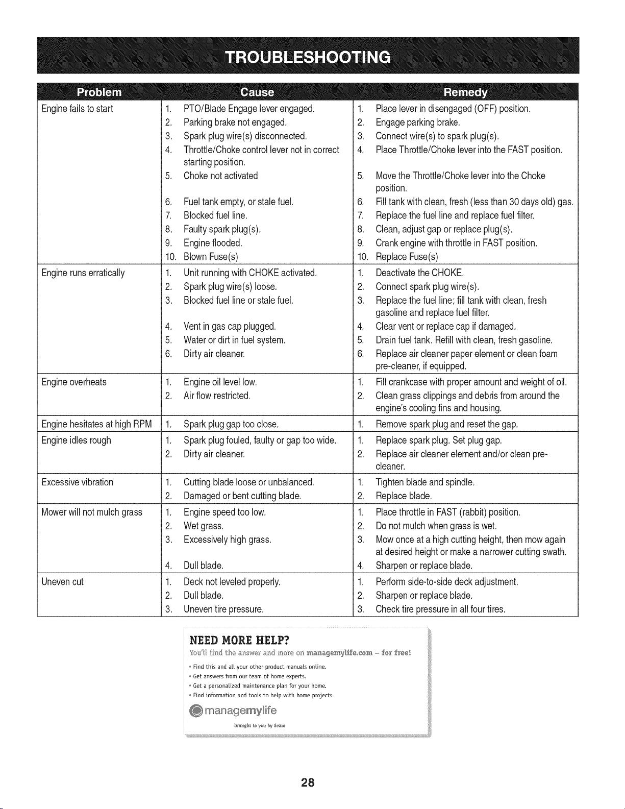
Enginefails to start
Enginerunserratically
1. PTO/BladeEngageleverengaged.
2. Parkingbrakenotengaged.
3. Sparkplugwire(s)disconnected.
4. Throttle/Chokecontrollevernot incorrect
startingposition.
5. Chokenotactivated
6. Fueltankempty,or stalefuel.
7. BIockedfuelline.
8. Faultysparkplug(s).
9. Engineflooded.
10. BlownFuse(s)
1. UnitrunningwithCHOKEactivated.
2. Sparkplugwire(s)loose.
3. Blockedfuel lineor stalefuel.
4. Ventingas cap plugged.
5. Waterordirt infuel system.
6. Dirtyair cleaner.
Engineoverheats 1. Engineoillevellow. 1.
2. Airflow restricted. 2.
Enginehesitatesat highRPM 1. Sparkpluggaptoo close. 1.
Engineidles rough 1. Sparkplugfouled,faultyor gaptoo wide. 1.
2. Dirtyair cleaner. 2.
Excessivevibration
Mowerwill not mulchgrass
Unevencut
1. Cuttingbladelooseor unbalanced.
2. Damagedor bentcuttingblade.
1. Enginespeedtoo low.
2. Wetgrass.
3. Excessivelyhighgrass.
4. Dullblade.
1. Decknot leveledproperly.
2. Dullblade.
3. Uneventire pressure.
1. Placeleverindisengaged(OFF)position.
2. Engageparkingbrake.
3. Connectwire(s)to sparkplug(s).
4. PlaceThrottle/Chokeleverintothe FASTposition.
5. MovetheThrottle/Chokeleverintothe Choke
position.
6. Filltankwith clean,fresh(less than30 daysold) gas.
7. Replacethe fuel lineand replacefuel filter.
8. Clean,adjustgapor replaceplug(s).
9. Crankenginewiththrottlein FASTposition.
10. ReplaceFuse(s)
1. Deactivatethe CHOKE.
2. Connectsparkplugwire(s).
3. Replacethe fuel line;fill tank withclean,fresh
gasolineandreplacefuel filter.
4. Clearventor replacecap if damaged.
5. Drainfuel tank. Refillwith clean,freshgasoline.
6. Replaceair cleanerpaperelementor cleanfoam
pre-cleaner,if equipped.
Fillcrankcasewith properamountandweightof oil.
Cleangrassclippingsanddebrisfrom aroundthe
engine'scoolingfinsandhousing.
Removesparkplugandresetthe gap.
Replacesparkplug.Set pluggap.
Replaceair cleanerelementand/orclean pre-
cleaner.
1. Tightenbladeand spindle.
2. Replaceblade.
1. Placethrottlein FAST(rabbit)position.
2. Do notmulchwhengrass is wet.
3. Mowonce at a highcuttingheight,then mowagain
at desiredheightor makea narrowercuttingswath.
4. Sharpenor replaceblade.
1. Performside-to-sidedeckadjustment.
2. Sharpenor replaceblade.
3. Checktire pressureinall four tires.
NEED MORE HELP?
Find this and aLLyour other product manuals online,
Get answers from our team of home experts.
Get a personalized maintenance plan for your home,
Find information and tools to help with home projects.
_o #At 1o ye b:_ Sea_s
28
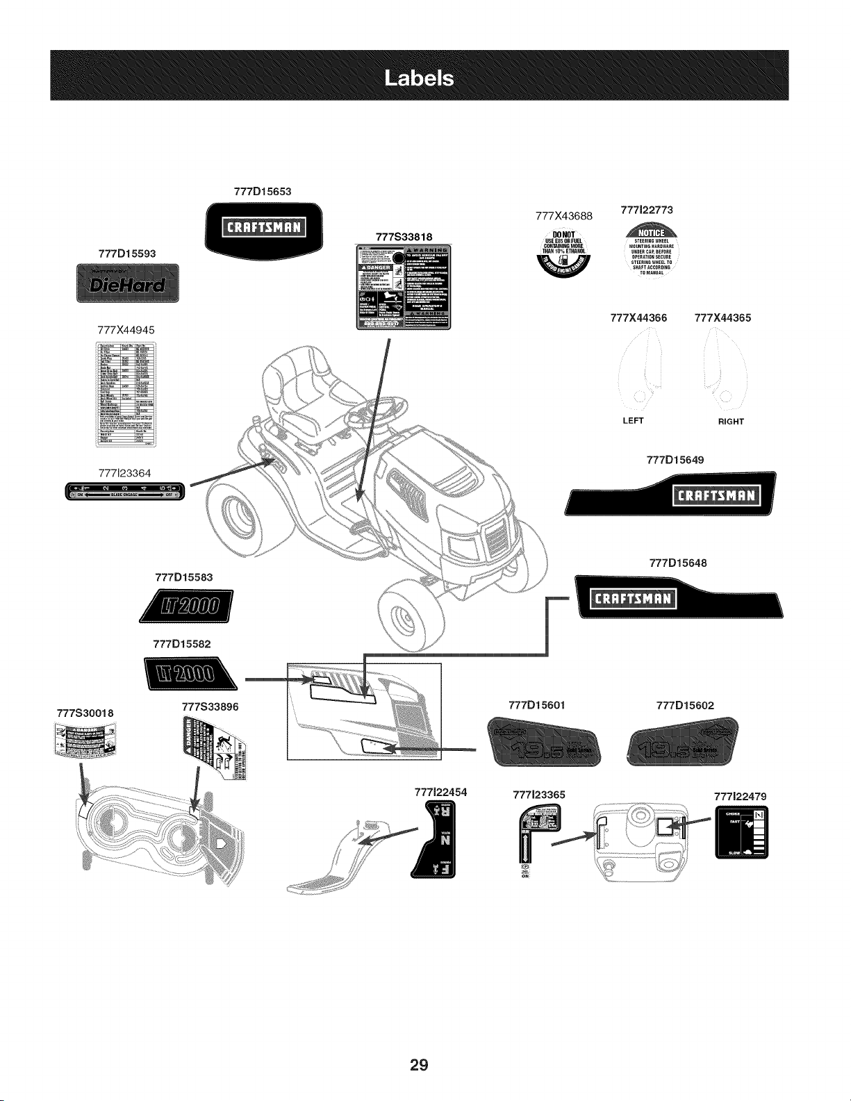
777D15593
777X44945
il_?, _° :_ I_ :
i_"'ro., ',m_
777123364
777D15653
777S33818
777X43688
777122773
DO NOT
USEE85ORFUEL STEERINGWHEEL
CONFININGMORE MOUNTINGHARDWARE
THAN10%ETHANOL UNDERCAP,BEFORE
OPERATIONSECURE
STEERINGWHEELTO
SHAFTACCORDING
TOMANUAL
777X44366 777X44365
,_ _ ii II
LEFT RIGHT
777D15649
777D15583
777D15648
777D15582
777S30018
": ::::::::Z[.....
777S33896
777122454
777D15601
777123365
777D15602
777122479
29
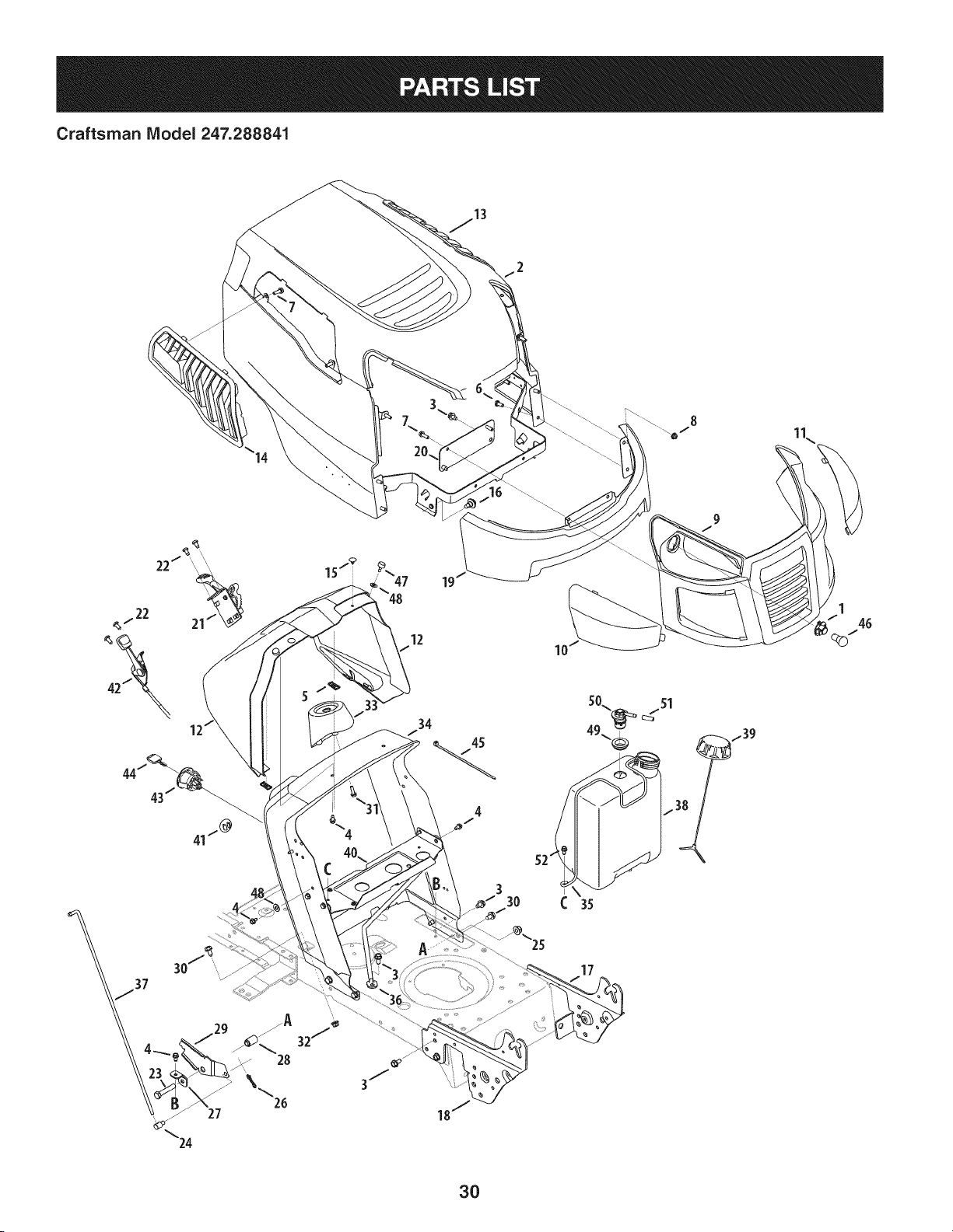
Craftsman IViodel 247.288841
3
30
I
10
17
/39
3O
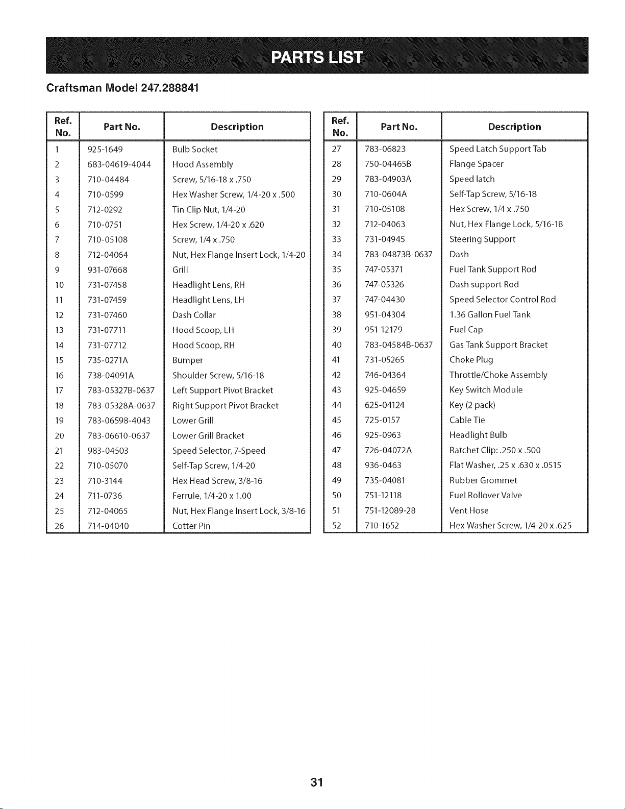
Craftsman Model 247.288841
Ref, I
No,
1 925-I 649
2 683-04619-4044
3 710-04484
4 710-0599
5 712-0292
6 710-0751
7 710-05108
8 712-04064
9 931-07668
I0 731-07458
11 731-07459
12 731-07460
13 731-07711
14 731-07712
15 735-0271A
16 738-04091A
17 783-05327B-0637
18 783-05328A-0637
19 783-06598-4043
20 783-06610-0637
21 983-04503
22 710-05070
23 710-3144
24 711-0736
25 712-04065
26 714-04040
Part No. Description
Bulb Socket
Hood Assembly
Screw, 5/16-18 x .750
Hex Washer Screw, 1/4-20 x .500
Tin Clip Nut, 1/4-20
Hex Screw, 1/4-20 x .620
Screw, 1/4 x .750
Nut, Hex Flange Insert Lock, 1/4-20
Grill
Headlight Lens, RH
Headlight Lens, LH
Dash Collar
Hood Scoop, LH
Hood Scoop, RH
Bumper
Shoulder Screw, 5/16-18
Left Support Pivot Bracket
Right Support Pivot Bracket
Lower Grill
Lower Grill Bracket
Speed Selector, 7-Speed
Self-Tap Screw, 1/4-20
Hex Head Screw, 3/8-16
Ferrule, 1/4-20 x 1.00
Nut, Hex Flange Insert Lock, 3/8-16
Cotter Pin
Ref, I
NO,
27 783-06823
28 750-04465B
29 783-04903A
30 710-0604A
31 710-05108
32 712-04063
33 731-04945
34 783-04873B-0637
35 747-05371
36 747-05326
37 747-04430
38 951-04304
39 951-12179
40 783-04584B-0637
41 731-05265
42 746-04364
43 925-04659
44 625-04124
45 725-0157
46 925-0963
47 726-04072A
48 936-0463
49 735-04081
50 751-12118
51 751-12089-28
52 710-1652
Part No, Description
Speed Latch Support Tab
Flange Spacer
Speed latch
Self-Tap Screw, 5/16-18
Hex Screw, 1/4 x .750
Nut, Hex Flange Lock, 5/16-18
Steering Support
Dash
Fuel Tank Support Rod
Dash support Rod
Speed Selector Control Rod
1.36 Gallon Fuel Tank
Fuel Cap
Gas Tank Support Bracket
Choke Plug
Throttle/Choke Assembly
Key Switch Module
Key (2 pack)
Cable Tie
Headlight Bulb
Ratchet Clip: .250 x .500
Flat Washer, .25 x .630 x .0515
Rubber Grommet
Fuel Rollover Valve
Vent Hose
Hex Washer Screw, 1/4-20 x .625
31
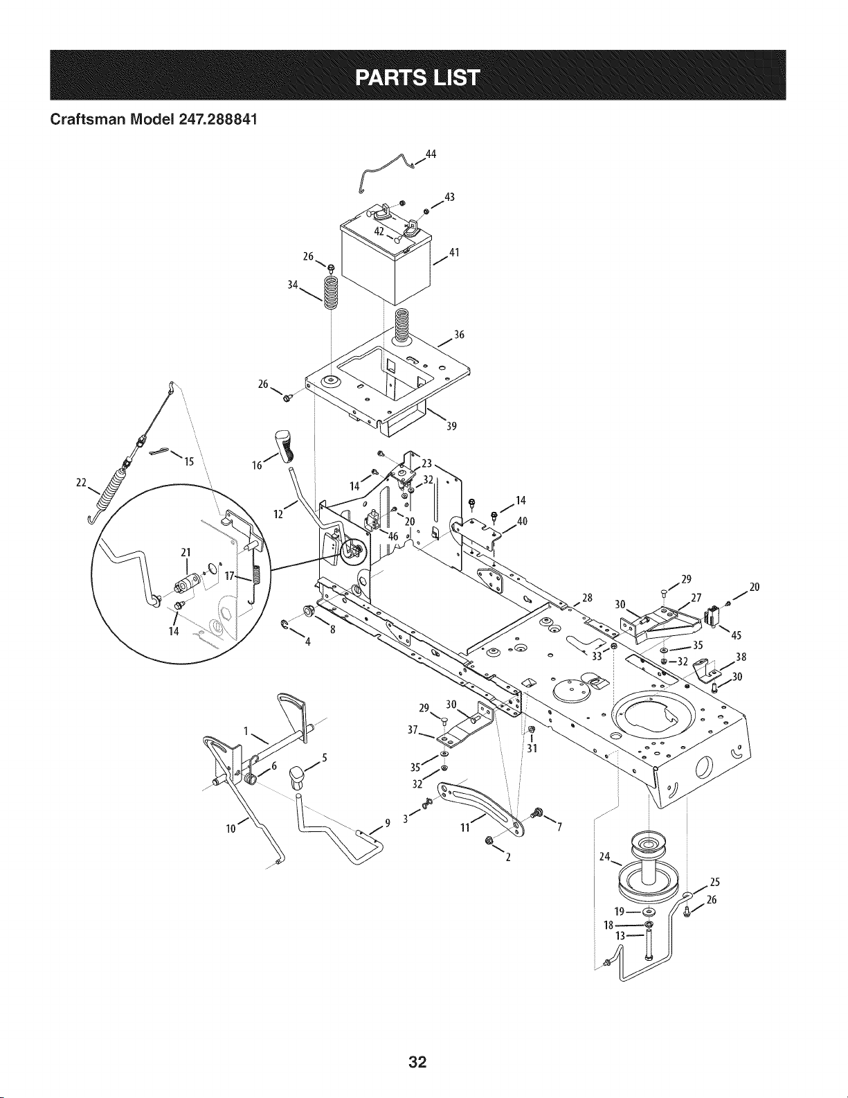
Craftsman IViodel 247.288841
36
22
21
14
12
39
28
30
45
38
11
%
2
32
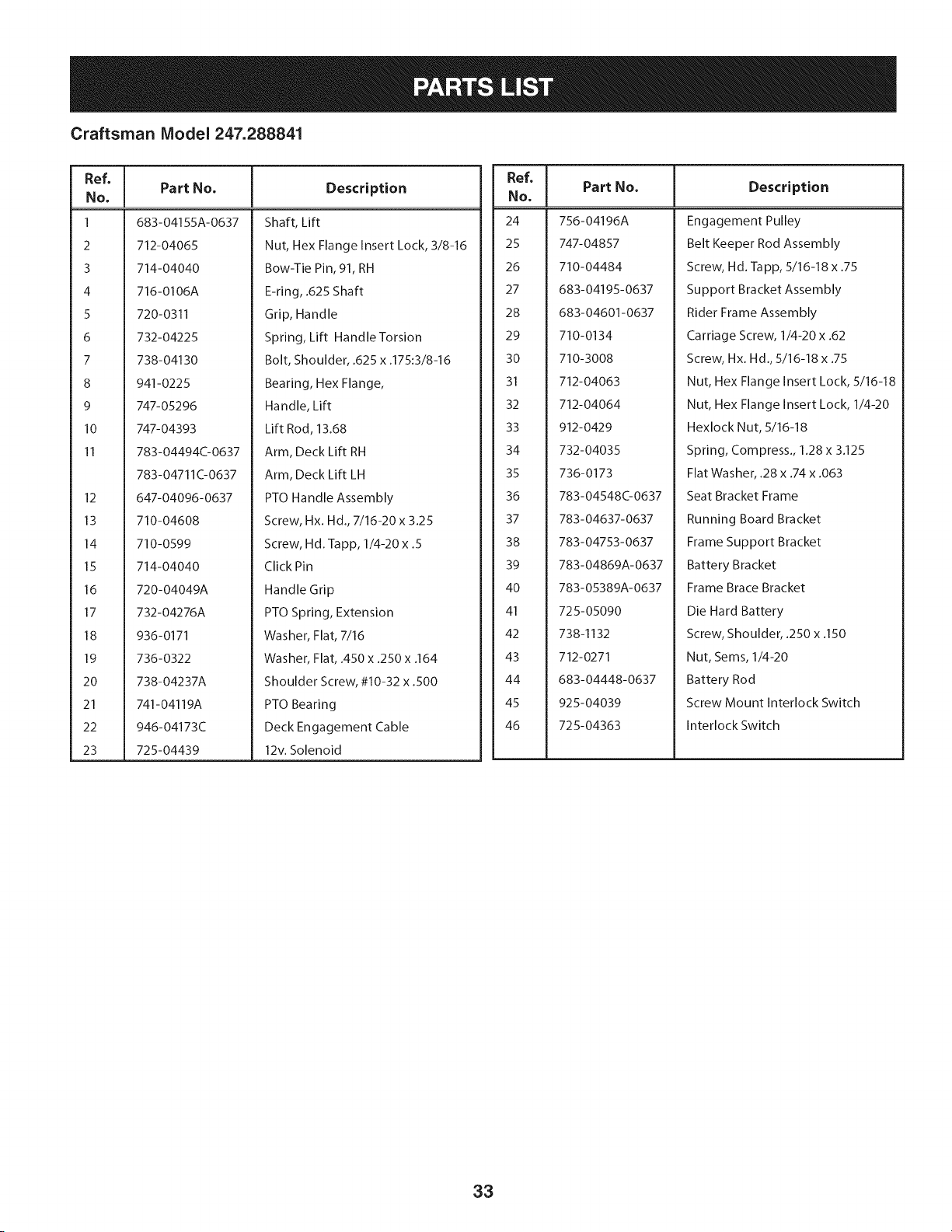
Craftsman Model 247.288841
Ref, [
No,
1 683-04155A-0637
2 712-04065
3 714-04040
4 716-0106A
5 720-0311
6 732-04225
7 738-04130
8 941-0225
9 747-05296
10 747-04393
11 783-04494C-0637
783-04711C-0637
12 647-04096-0637
13 710-04608
14 710-0599
15 714-04040
16 720-04049A
17 732-04276A
18 936-0171
19 736-0322
20 738-04237A
21 741-04119A
22 946-04173C
23 725-04439
Part No. Description
Shaft, Lift
Nut, Hex Flange Insert Lock, 3/8-16
Bow-Tie Pin, 91, RH
E-ring, .625 Shaft
Grip, Handle
Spring, Lift Handle Torsion
Bolt, Shoulder, .625 x .175:3/8-16
Bearing, Hex Flange,
Handle, Lift
Lift Rod, 13.68
Arm, Deck Lift RH
Arm, Deck Lift LH
PTO Handle Assembly
Screw, Hx. Hd., 7/16-20 x 3.25
Screw, Hd. Tapp, 1/4-20 x .5
Click Pin
Handle Grip
PTO Spring, Extension
Washer, Flat, 7/16
Washer, Flat, .450 x .250 x .164
Shoulder Screw, #10-32 x .500
PTO Bearing
Deck Engagement Cable
12v. Solenoid
Ref, I
No,
24 756-04196A
25 747-04857
26 710-04484
27 683-04195-0637
28 683-04601-0637
29 710-0134
30 710-3008
31 712-04063
32 712-04064
33 912-0429
34 732-04035
35 736-0173
36 783-04548O0637
37 783-04637-0637
38 783-04753-0637
39 783-04869A-0637
40 783-05389A-0637
41 725-05090
42 738-1132
43 712-0271
44 683-04448-0637
45 925-04039
46 725-04363
Part No. Description
Engagement Pulley
Belt Keeper Rod Assembly
Screw, Hd. Tapp, 5/16-18 x .75
Support Bracket Assembly
Rider Frame Assembly
Carriage Screw, 1/4-20 x .62
Screw, Hx. Hd., 5/16-18 x .75
Nut, Hex Flange Insert Lock, 5/16-18
Nut, Hex Flange Insert Lock, 1/4-20
Hexlock Nut, 5/16-18
Spring, Compress., 1.28 x 3.125
Flat Washer, .28 x .74 x .063
Seat Bracket Frame
Running Board Bracket
Frame Support Bracket
Battery Bracket
Frame Brace Bracket
Die Hard Battery
Screw, Shoulder, .250 x .150
Nut, Seres, 1/4-20
Battery Rod
Screw Mount Interlock Switch
Interlock Switch
33
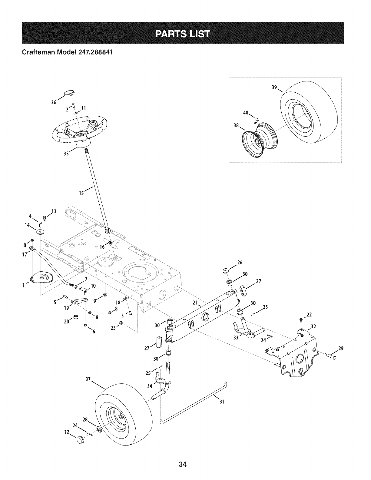
Craftsman IViodel 247.288841
39
38._ _ z
4 713
21
30
25
24 _ ............
22
32
/
34
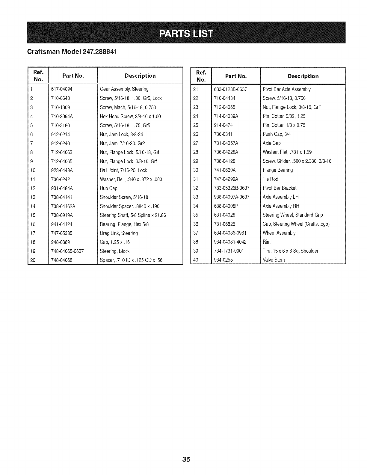
Craftsman IViodel 247.288841
Ref, I
No,
1 617-04094
2 710-0643
3 710-1309
4 710-3094A
5 710-3180
6 912-0214
7 912-0240
8 712-04063
9 712-04065
10 923-0448A
11 736-0242
12 931-0484A
13 738-04141
14 738-04162A
15 738-0919A
16 941-04124
17 747-05385
18 948-0389
19 748-04065-0637
20 748-04068
Part No. Description
GearAssembly,Steering
Screw,5/16-18,1.00,Gr5,Lock
Screw,Mach,5/16-18,0.750
HexHeadScrew,3/8-16x 1.00
Screw,5/16-18,1.75,Gr5
Nut,JamLock,3/8-24
Nut,Jam,7/16-20,Gr2
Nut,FlangeLock,5/16-18,Grf
Nut,FlangeLock,3/8-16,Grf
BallJoint,7/16-20,Lock
Washer,Bell, .340x .872x .060
HubCap
ShoulderScrew,5/16-18
ShoulderSpacer,.8840 x .190
SteeringShaft,5/8 Splinex 21.86
Bearing,Flange,Hex5/8
DragLink,Steering
Cap, 1.25x .16
Steering,Block
Spacer,.710IDx .125ODx .56
Ref. I
No,
21 683-0128B-0637
22 710-04484
23 712-04065
24 714-04039A
25 914-0474
26 736-0341
27 731-04057A
28 736-04228A
29 738-04128
30 741-0660A
31 747-04299A
32 783-05326B-0637
33 938-04007A-0637
34 638-04008P
35 631-04028
36 731-06825
37 634-04086-0961
38 934-04081-4042
39 734-1731-0901
40 934-0255
Part No. Description
PivotBar AxleAssembly
Screw,5/16-18,0.750
Nut, FlangeLock, 3/8-16,GrF
Pin, Cotter,5/32, 1.25
Pin, Cotter,1/8x 0.75
PushCap,3/4
AxleCap
Washer,Flat,.781x 1.59
Screw,Shlder,.500x 2.380,3/8-16
FlangeBearing
TieRod
PivotBar Bracket
AxleAssemblyLH
AxleAssemblyRH
SteeringWheel,StandardGrip
Cap,SteeringWheel(Crafts.logo)
WheelAssembly
Rim
Tire, 15x 6 x 6 Sq.Shoulder
ValveStem
35
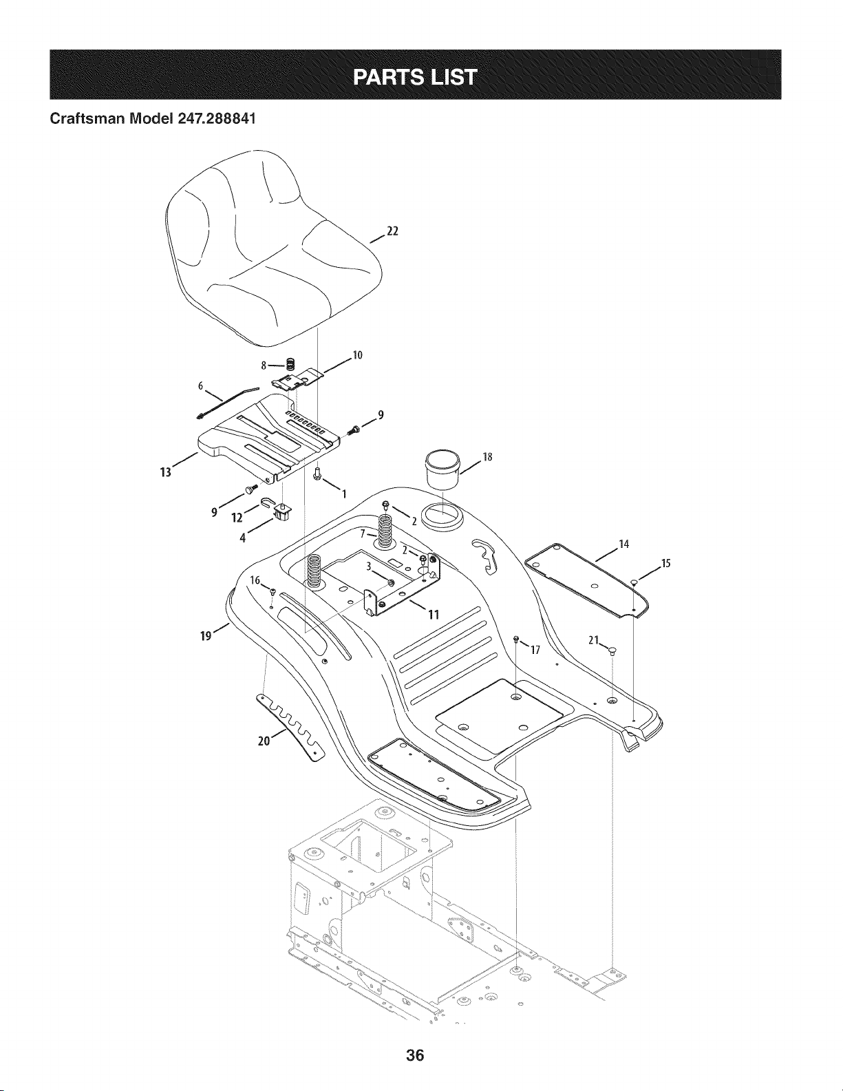
Craftsman Model 247.288841
13
\
11
36
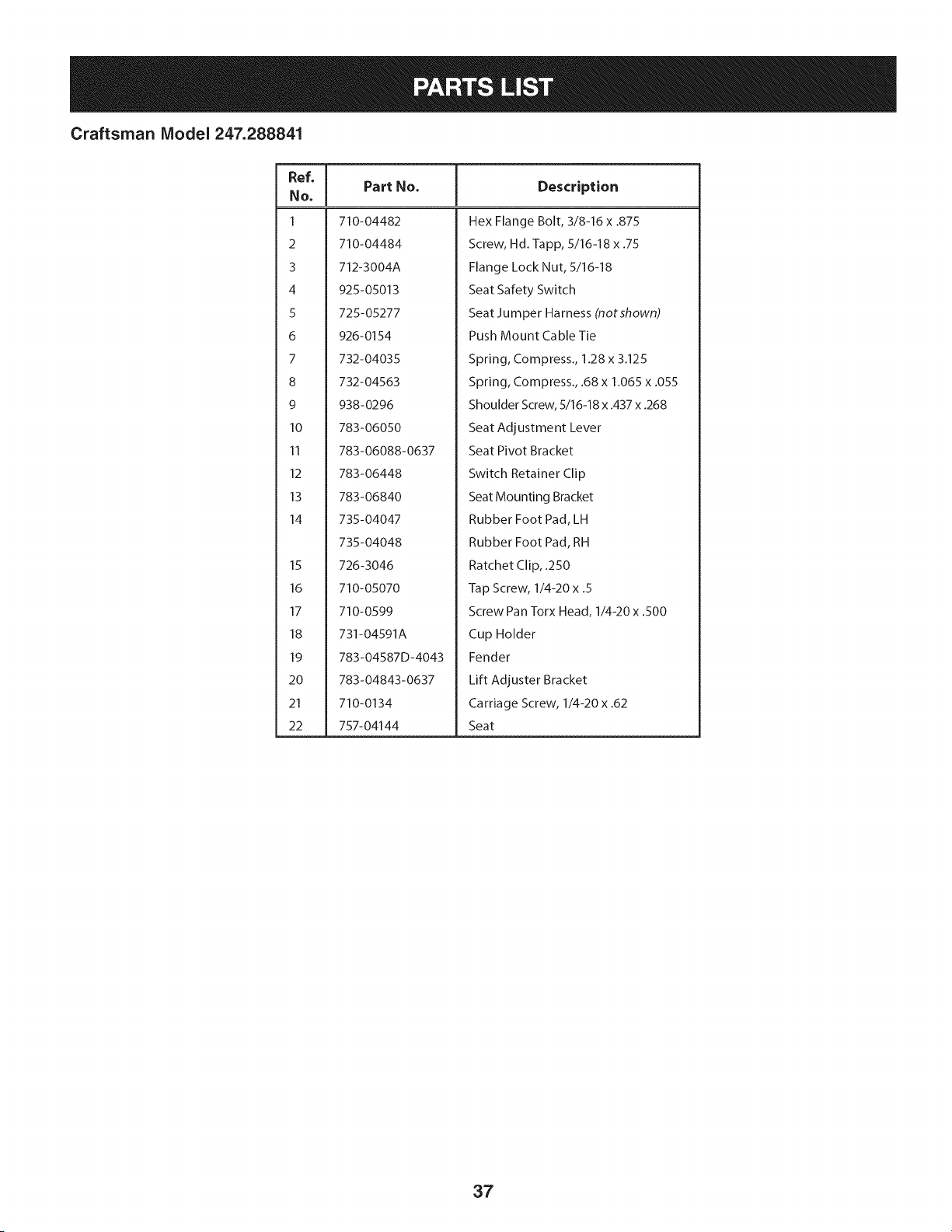
Craftsman Model 247.288841
Ref, [
No,
I 710-04482
2 710-04484
3 712-3004A
4 925-05013
5 725-05277
6 926-0154
7 732-04035
8 732-04563
9 938-0296
10 783-06050
11 783-06088-0637
12 783-06448
13 783-06840
14 735-04047
735-04048
15 726-3046
16 710-05070
17 710-0599
18 731-04591A
19 783-04587D-4043
20 783-04843-0637
21 710-0134
22 757-04144
Part No. Description
Hex Flange Bolt, 3/8-16 x .875
Screw, Hd.-lapp, 5/16-18 x .75
Flange Lock Nut, 5/16-18
Seat Safety Switch
Seat Jumper Harness (notshown)
Push Mount Cable Tie
Spring, Compress., 1.28 x 3.125
Spring, Compress., .68 x 1.065 x .055
Shoulder Screw, 5/16-18 x .437 x .268
Seat Adjustment Lever
Seat Pivot Bracket
Switch Retainer Clip
Seat Mounting Bracket
Rubber Foot Pad, LH
Rubber Foot Pad, RH
Ratchet Clip, .250
Tap Screw, 1/4-20 x .5
Screw Pan Torx Head, 1/4-20 x .500
Cup Holder
Fender
Lift Adjuster Bracket
Carriage Screw, 1/4-20 x .62
Seat
37
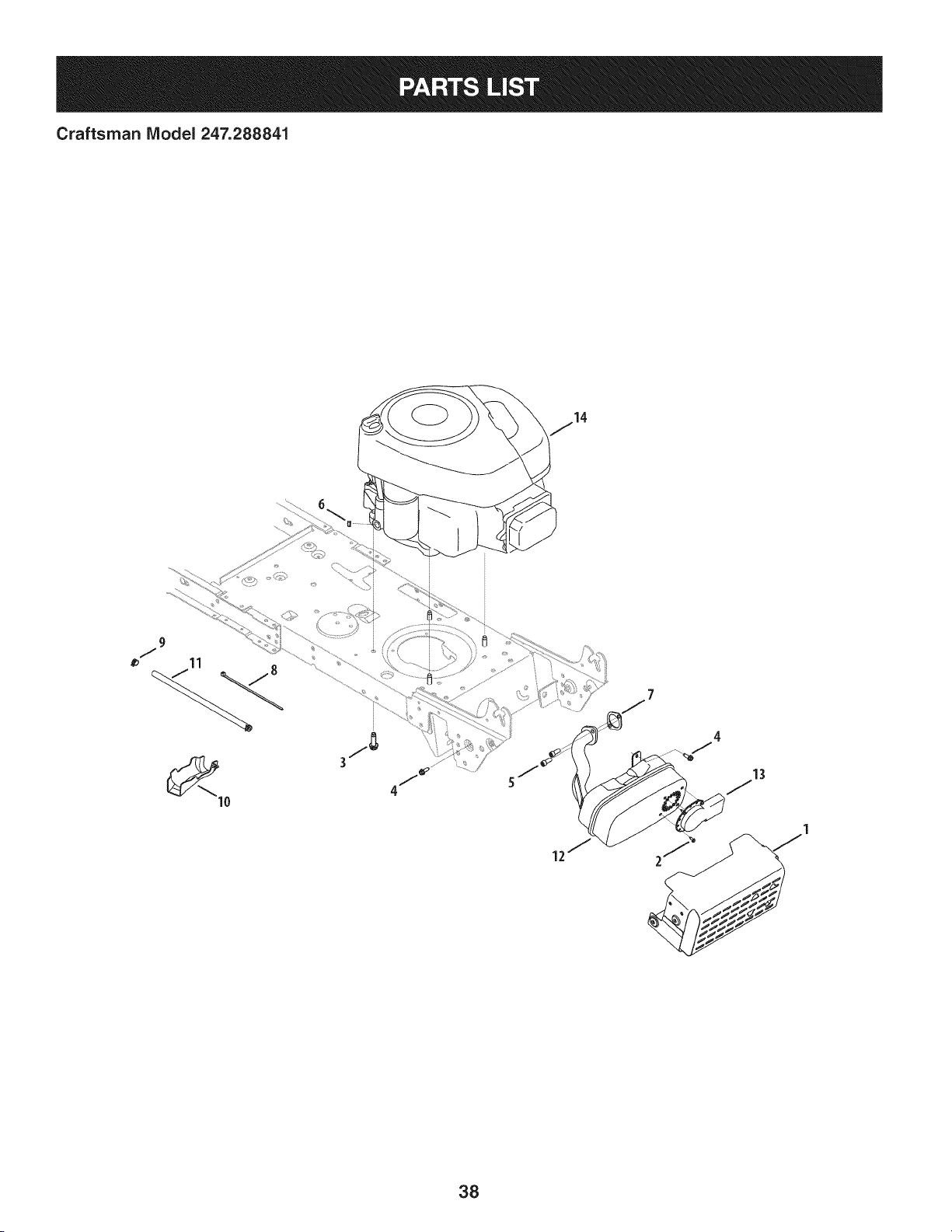
Craftsman IViodel 247.288841
13
38
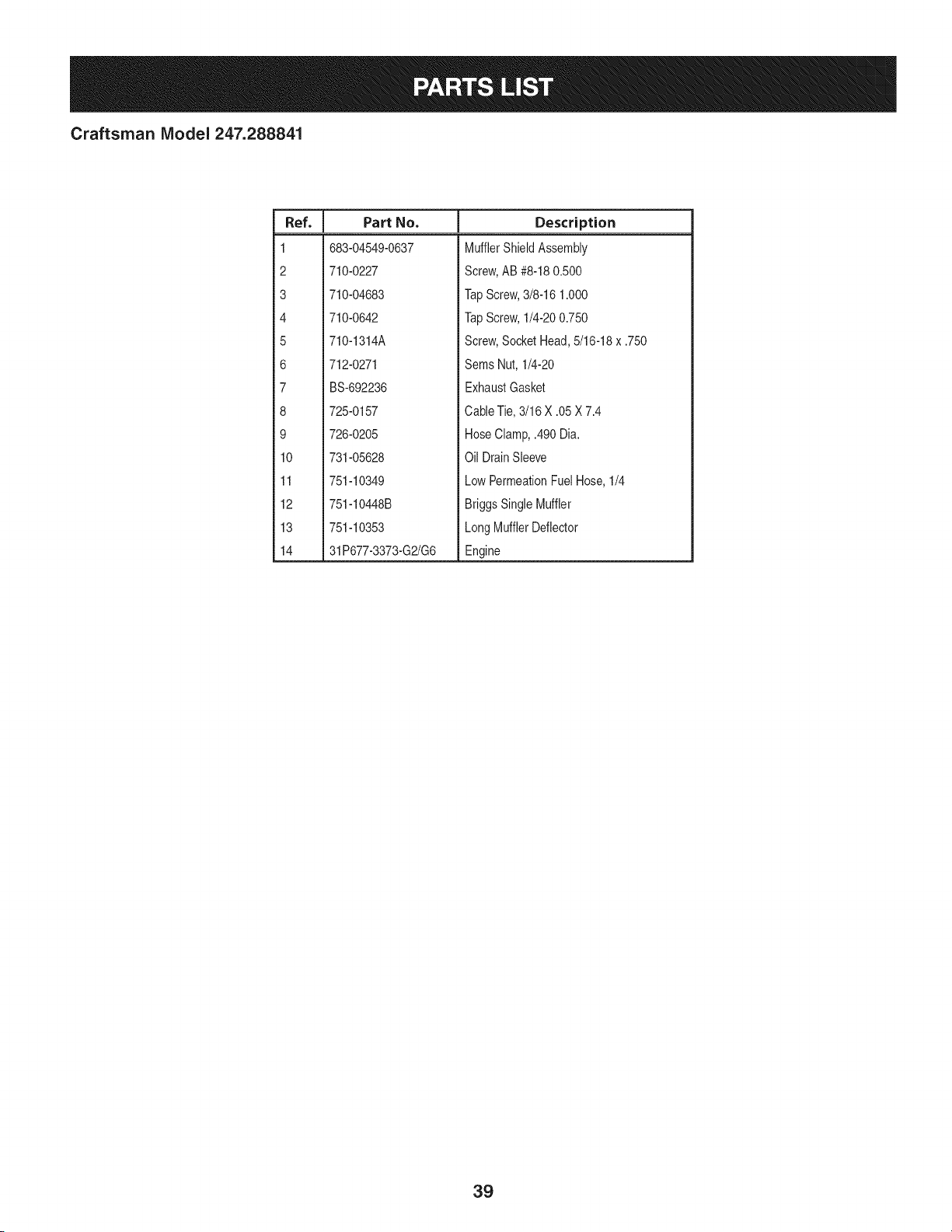
Craftsman IViodel 247.288841
I
Ref.
I Part No.
1 683-04549-0637
2 710-0227
3 710-04683
4 710-0642
5 710-1314A
6 712-0271
7 BS-692236
8 725-0157
9 726-0205
10 731-05628
11 751-10349
12 751-10448B
13 751-10353
14 31P677-3373-G2/G6
Descriptien
MufflerShieldAssembly
Screw,AB #8-180.500
TapScrew,3/8-16 1.000
TapScrew,1/4-200.750
Screw,SocketHead,5/16-18x .750
Sems Nut, 1/4-20
ExhaustGasket
CableTie,3/16 X .05 X 7.4
HoseClamp,.490 Dia.
Oil DrainSleeve
LowPermeationFuelHose,1/4
BriggsSingleMuffler
LongMufflerDeflector
Engine
39
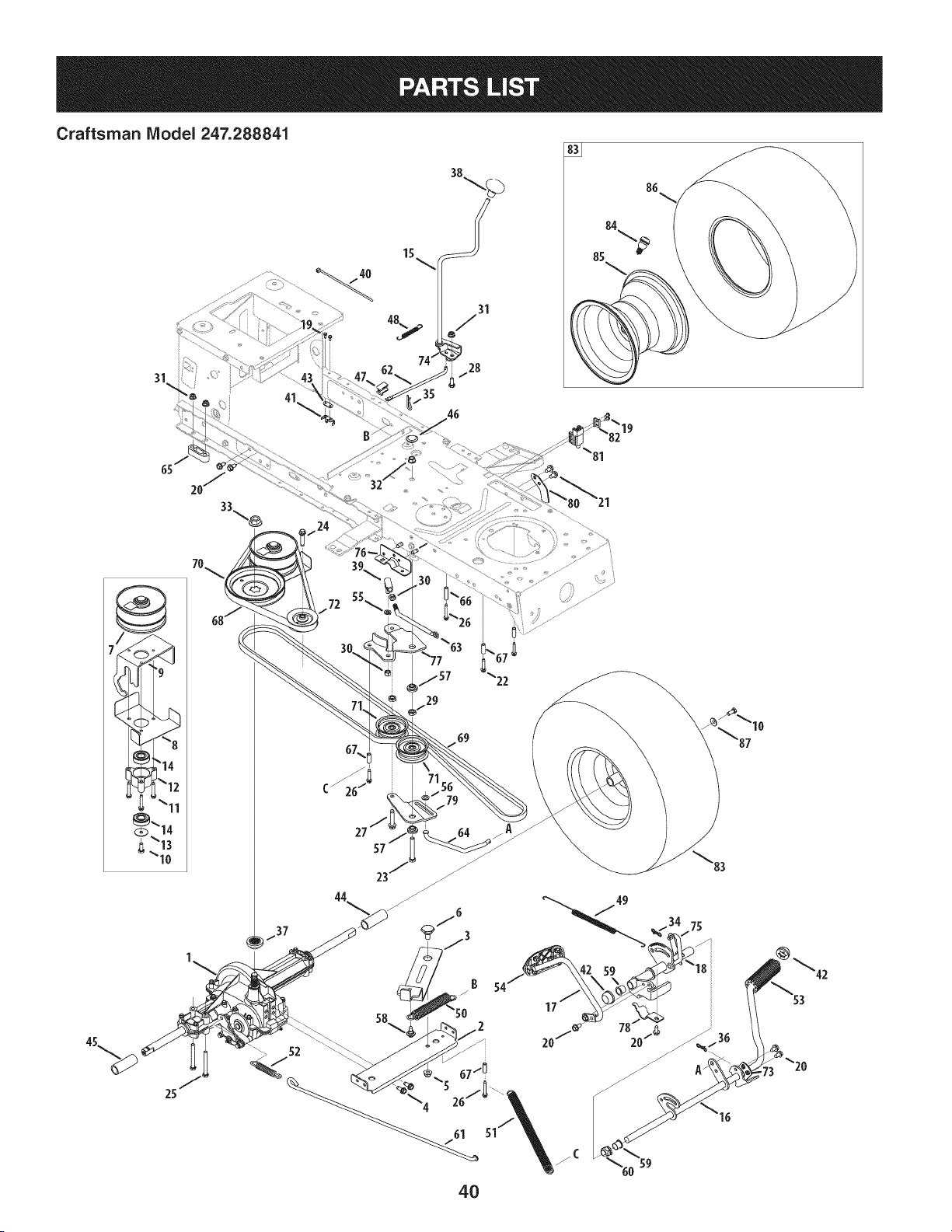
Craftsman Model 247.288841
41
15
35
19
29
B 54
17
4O
20/_
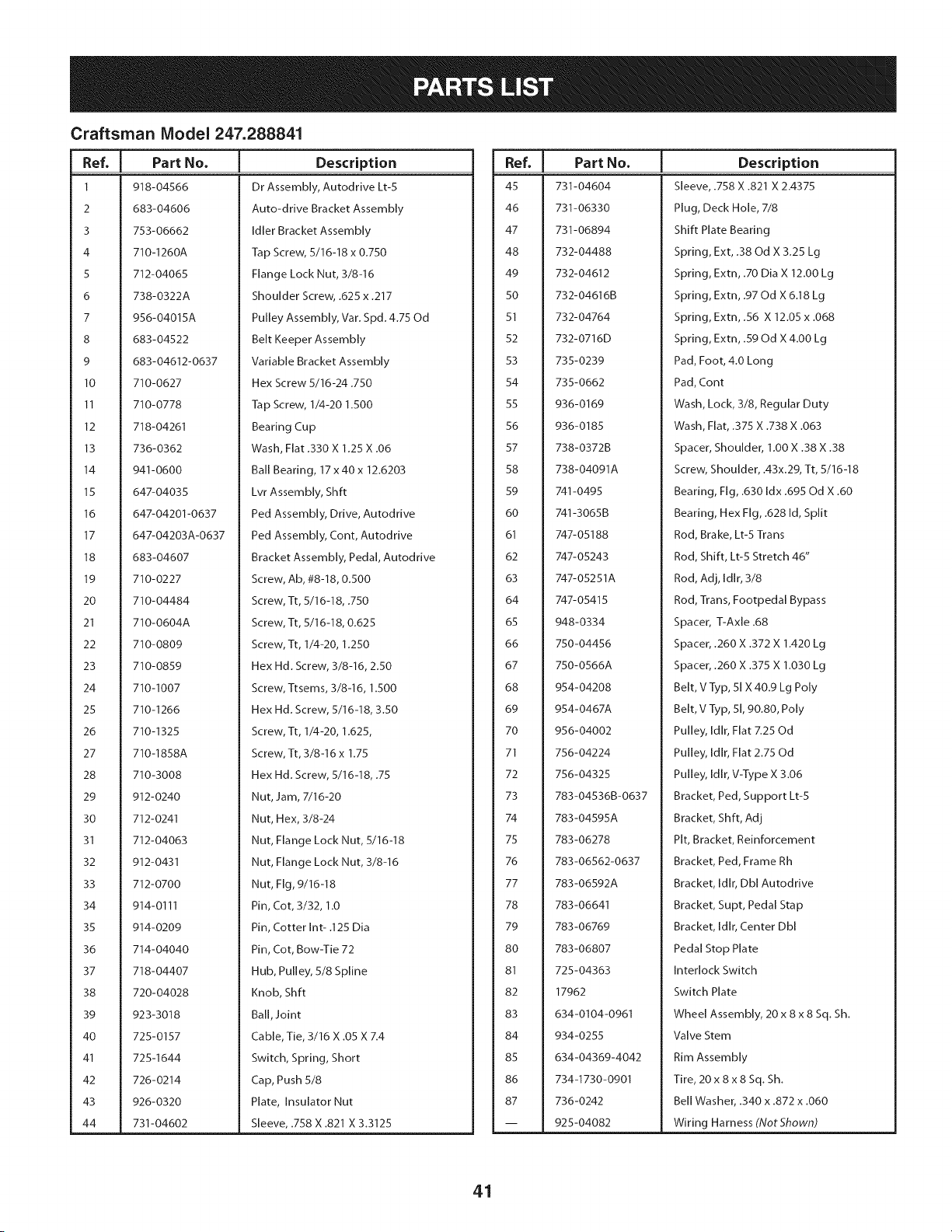
Craftsman Model 247.288841
I
Ref, I Part No.
1 918-04566
2 683-04606
3 753-06662
4 710-1260A
5 712-04065
6 738-0322A
7 956-04015A
8 683-04522
9 683-04612-0637
10 710-0627
11 710-0778
12 718-04261
13 736-0362
14 941-0600
15 647-04035
16 647-04201-0637
17 647-04203A-0637
18 683-04607
19 710-0227
20 710-04484
21 710-0604A
22 710-0809
23 710-0859
24 710-1007
25 710-1266
26 710-1325
27 710-1858A
28 710-3008
29 912-0240
30 712-0241
31 712-04063
32 912-0431
33 712-0700
34 914-0111
35 914-0209
36 714-04040
37 718-04407
38 720-04028
39 923-3018
40 725-0157
41 725-1644
42 726-0214
43 926-0320
44 731-04602
Description
Dr Assembly, Autodrive Lt-5
Auto-drive Bracket Assembly
Idler Bracket Assembly
Tap Screw, 5/16-18 x 0.750
Flange Lock Nut, 3/8-16
Shoulder Screw, .625 x .217
Pulley Assembly, Var. Spd. 4.75 Od
Belt Keeper Assembly
Variable Bracket Assembly
Hex Screw 5/16-24.750
Tap Screw, 1/4-20 1.500
Bearing Cup
Wash, Flat .330 X 1.25 X .06
Ball Bearing, 17 x 40 x 12.6203
Lvr Assembly, Shft
Ped Assembly, Drive, Autodrive
Ped Assembly, Cont, Autodrive
Bracket Assembly, Pedal, Autodrive
Screw, Ab, #8-18, 0.500
Screw, Tt, 5/16-18, .750
Screw, Tt, 5/16-18, 0.625
Screw, Tt, 1/4-20, 1.250
Hex Hd. Screw, 3/8-16, 2.50
Screw, Ttsems, 3/8-16, 1.500
Hex Hd. Screw, 5/16-18, 3.50
Screw, Tt, 1/4-20, 1.625,
Screw, Tt, 3/8-16 x 1.75
Hex Hd. Screw, 5/16-18, .75
Nut, Jam, 7/16-20
Nut, Hex, 3/8-24
Nut, Flange Lock Nut, 5/16-18
Nut, Flange Lock Nut, 3/8-16
Nut, Fig, 9/16-18
Pin, Cot, 3/32, 1.0
Pin, Cotter Int- .125 Dia
Pin, Cot, Bow-Tie 72
Hub, Pulley, 5/8 Spline
Knob, Shft
Bali,Joint
Cable, Tie, 3/16 X .05 X 7.4
Switch, Spring, Short
Cap, Push 5/8
Plate, Insulator Nut
Sleeve, .758 X .821 X 3.3125
|
Ref, I Part No.
45 731-04604
46 731-06330
47 731-06894
48 732-04488
49 732-04612
50 732-04616B
51 732-04764
52 732-0716D
53 735-0239
54 735-0662
55 936-0169
56 936-0185
57 738-0372B
58 738-04091A
59 741-0495
60 741-3065B
61 747-05188
62 747-05243
63 747-05251A
64 747-05415
65 948-0334
66 750-04456
67 750-0566A
68 954-04208
69 954-0467A
70 956-04002
71 756-04224
72 756-04325
73 783-04536B-0637
74 783-04595A
75 783-06278
76 783-06562-0637
77 783-06592A
78 783-06641
79 783-06769
80 783-06807
81 725-04363
82 17962
83 634-0104-0961
84 934-0255
85 634-04369-4042
86 734-1730-0901
87 736-0242
-- 925-04082
Description
Sleeve, .758 X .821 X 2.4375
Plug, Deck Hole, 7/8
Shift Plate Bearing
Spring, Ext, .38 Od X 3.25 Lg
Spring, Extn, .70 Dia X 12.00 Lg
Spring, Extn, .97 Od X 6.18 Lg
Spring, Extn, .56 X 12.05 x .068
Spring, Extn, .59 Od X 4.00 Lg
Pad, Foot, 4.0 Long
Pad, Cont
Wash, Lock, 3/8, Regular Duty
Wash, Flat, .375 X .738 X .063
Spacer, Shoulder, 1.00 X .38 X .38
Screw, Shoulder, A3x.29, Tt, 5/16-18
Bearing, Fig, .630 Idx .695 Od X .60
Bearing, Hex Fig, .628 Id, Split
Rod, Brake, Lt-5 Trans
Rod, Shift, Lt-5 Stretch 46"
Rod, Adj, Idlr, 3/8
Rod, Trans, Footpedal Bypass
Spacer, T-Axle .68
Spacer, .260 X .372 X 1.420 Lg
Spacer, .260 X .375 X 1.030 Lg
Belt, V Typ, 51 X 40.9 Lg Poly
Belt, V Typ, 51,90.80, Poly
Pulley, Idlr, Flat 7.25 Od
Pulley, Idlr, Flat 2.75 Od
Pulley, Idlr, V-Type X 3.06
Bracket, Ped, Support Lt-5
Bracket, Shft, Adj
Pit, Bracket, Reinforcement
Bracket, Ped, Frame Rh
Bracket, Idlr, Dbl Autodrive
Bracket, Supt, Pedal Stap
Bracket, Idlr, Center Dbl
Pedal Stop Plate
Interlock Switch
Switch Plate
Wheel Assembly, 20 x 8 x 8 Sq. Sh.
Valve Stem
Rim Assembly
Tire, 20 x 8 x 8 Sq. Sh.
Bell Washer, .340 x .872 x .060
Wiring Harness (NotShown)
41
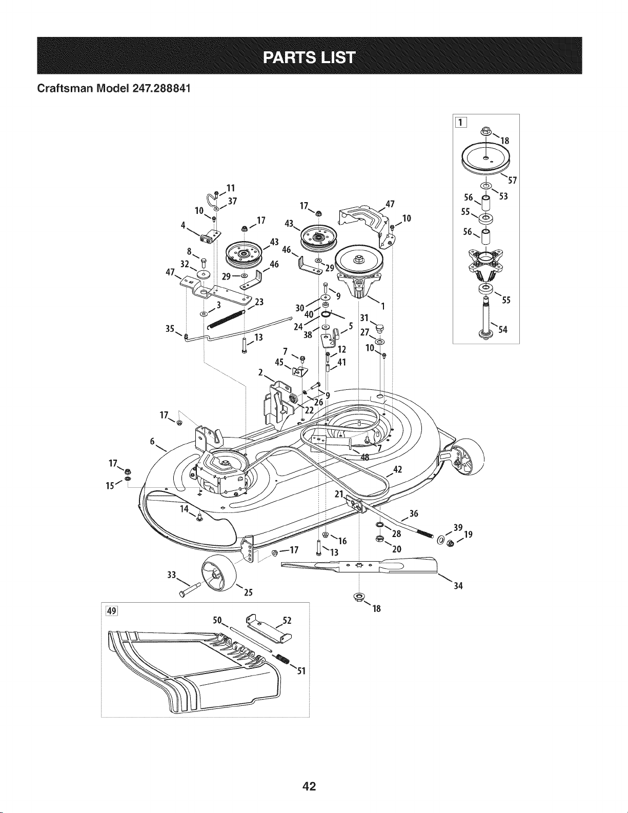
Craftsman Model 247.288841
6
\
13
7 \_
41
42
@_16
2O
34
42

Craftsman Model 247.288841
Ref, [
No,
1 918-04822A
2 683-0254B-0637
3 936-0344
4 983-04511
5 983-04525
6 983-04572-0637
7 710-04484
8 710-0514
9 710-0528
10 710-0599
11 710-0642
12 710-0778
13 710-3144
14 710-3178
15 712-0229
16 712-04063
17 712-04065
18 712-0417A
19 712-04243
20 912-0641
21 714-04043
22 917-04074
23 932-0384
24 732-04727
25 734-04155
26 936-0119
27 736-0187
28 736-0225
29 736-0262
Part No. Description
Spindle Pulley Assembly
Deck Hanger Bracket Assembly
Wash, Flat, .385 x 1.0 x .030
Brake Assembly
Brake Assembly
Deck
Screw, 5/16-18 x .750
Screw, 3/8-16 x 1.00
Hex Screw, 5/16-18 x 1.25
Screw, 1/4-20 x .500
Screw, 1/4-20 x .750
Screw, 1/4-20 x 1.50
Hex Head Screw, 3/8-16
Carriage Bolt, 3/8-16 x .75
Push Nut, 3/8
Flangelock Nut, 5/16-18
Flangelock Nut, 3/8-16
Flange Nut, 5/8-18
Flangelock Nut, 1/2-13
Hex Nut, M16 - 1.5
Cotter Pin, Bow-Tie
Deck Adjuster Gear
Extension Spring, .62 x 6.12
Torsion Spring, 1.0 x 1.17
Deck Wheel, 5" Dia. Ball
Lock Washer, 5/16
Flat Washer, .64 x 1.24 x .06
Flat Washer, .5/8 Int. Tth.
Flat Washer, .385 x .870 x .092
Ref, I
No,
30 736-0362
31 738-04146
32 738-04162A
33 938-3056
34 942-04308
35 747-05105
36 747-05141A
37 747-05323
38 748-0234
39 748-04069
40 750-0258
41 750-0566A
42 954-04060B
43 756-04129B
44 783-05946
45 783-06243-0637
46 783-06368A-0637
47 783-06424A-0637
48 783-06643-0637
49 631-04288
50 711-04847B
51 732-04372
52 783-06074A
53 936-0351
54 738-1186A
55 941-0919
56 750-04936
57 956-1227
Part No. Description
Flat Washer, .330 x 1.25 x .06
Bolt Plug, M16 x 1.5
Shoulder Spacer, .8840 x .190
Shoulder Bolt, 3/8-16
Cutting Blade, 21.23": 2 in 1
Brake Control Rod
Deck Lift Rod
Belt Keeper Rod
Shoulder Spacer
Deck Lift Pivot Cup
Spacer
Spacer
V-Type Belt, 96.5
Idler Pulley, 4.25 Diameter
Idler Pivot Bracket
Deck Cable Engagement Bracket
Belt Pulley Guard
Deck Belt Cover
Deck Support Bracket
Chute Deflector Assembly
Hinge Pin
Torsion Spring, .44 x 2.0
Chute Bracket
Flat Washer, .760 x 1.50
Spindle Shaft
Ball Bearing, .787 x 1.85 x .551
Spacer, .792 x 1.060 x 1.860
Deck Pulley, 6.3 dia.
43
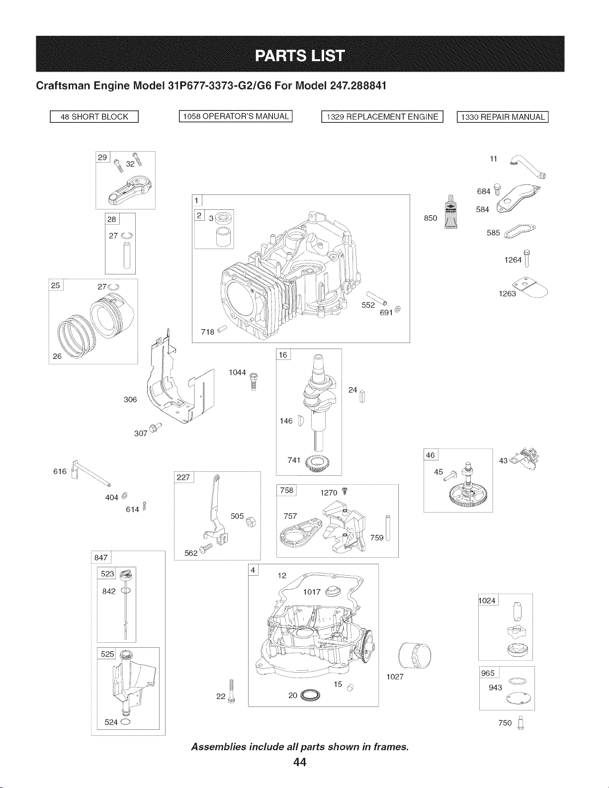
Craftsman Engine Model 31P677=3373=G2/G6 For Model 247.288841
48 SHORT BLOCK I 11058 OPERATOR'S MANUALI I 1329 REPLACEMENT ENGINE I 11330 REPAIR MANUALI
291. _,
i
2_J _ _
3_ ¢/I
:
\ J
2\\
718_ _
2
' ' 1044
307 @_
616
404 _
614 [!
847
842 _>
i227i
16i
741
757
1
¢i
22
12
759
1027
Assemblies include all parts shown in frames.
44
11
85o
684 _ _-_
584 '_._
585
1264
1263 *'\. _
i
.........................i...............................................
......................y................................................
965i
943
750
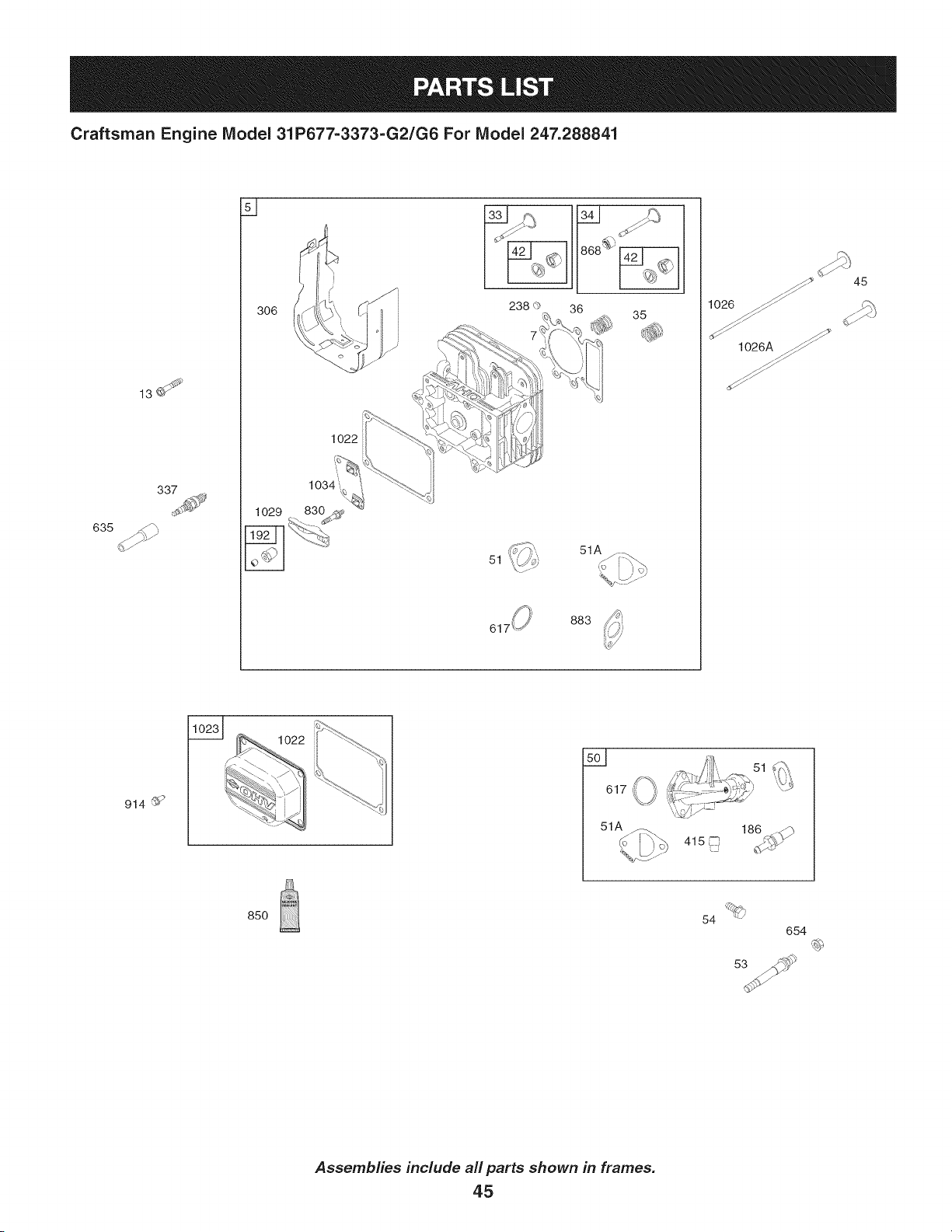
Craftsman Engine Model 31P677=3373=G2/G6 For Model 247.288841
635
13U
306
1022
1034i'_,¢
1029 830
j_.J
238 <')
51
36 35
883
_ 45
1026 _z zS _
_ _'
1026A _
914 _
617
85O
54
654
Assemblies include all parts shown in frames.
45
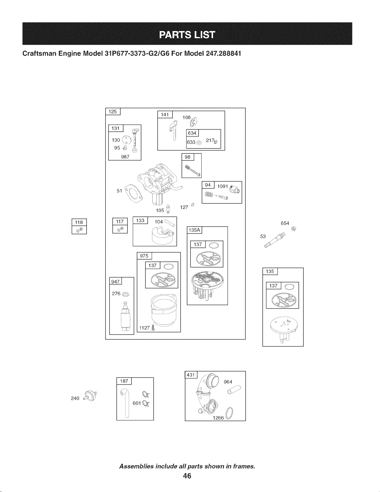
Craftsman Engine Model 31P677=3373=G2/G6 For Model 247.288841
13o
95_ /_9
987
51
276 (_._
1o8_._
217_
127
1127
654
_ S-"_ ,
6Ol_
964
1266
Assemblies include all parts shown in frames.
46
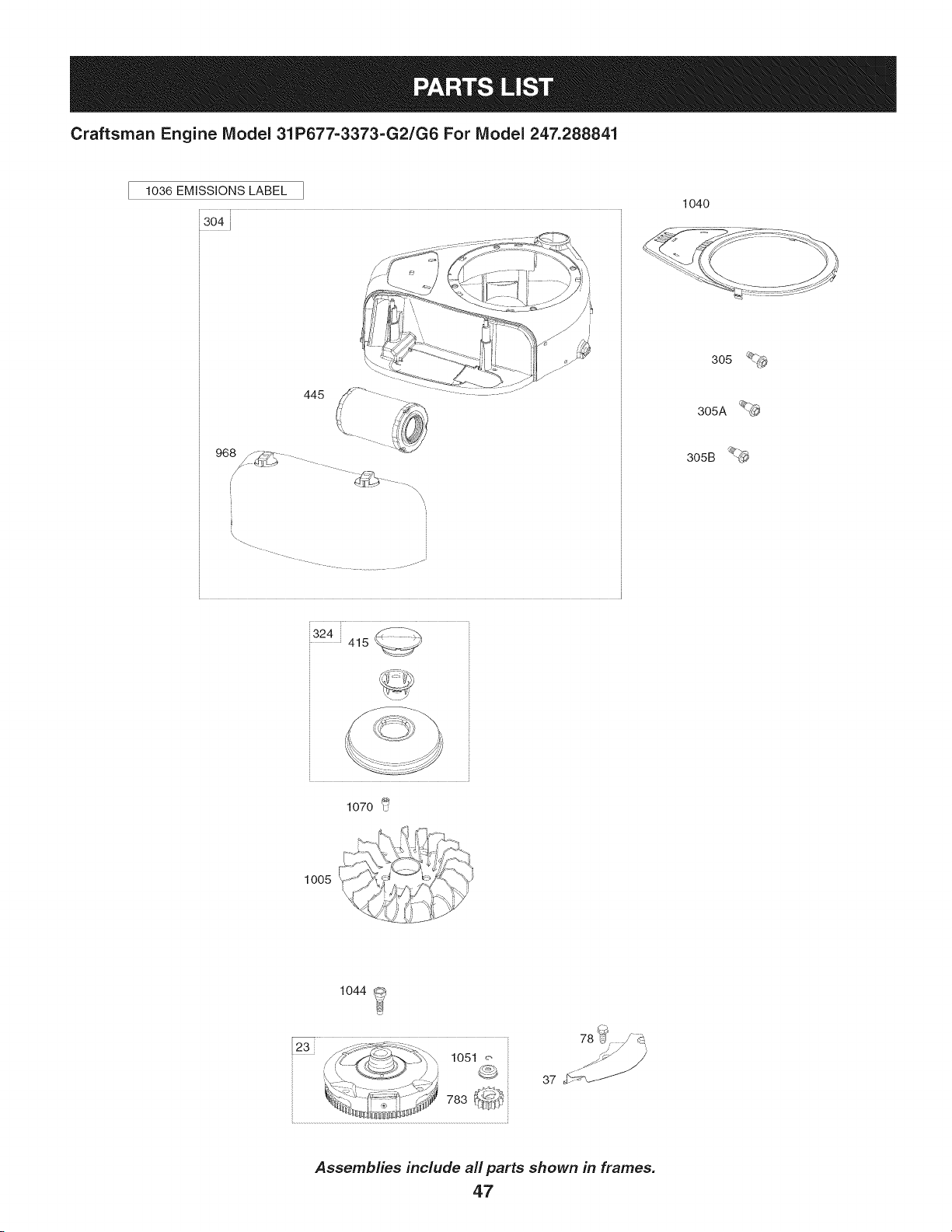
Craftsman Engine Model 31P677-3373-G2/G6 For Model 247.288841
1036 EMISSIONS LABEL
304i
445
968 _-S, yT_,
\
\.
.... J
324415 _,_._.Y
1040
305
1005
1070 u
_s -_,
7-s, _-,'W"
1044 i_
@
78 _J
7_ ....
37 __
Assemblies include all parts shown in frames.
47
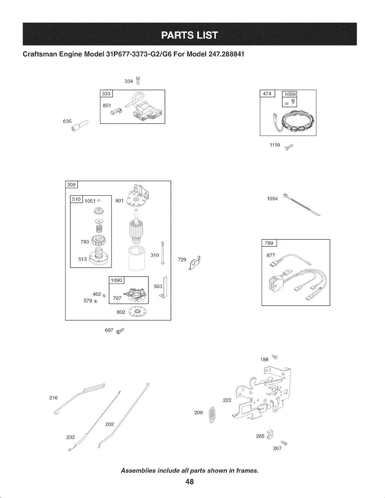
Craftsman Engine Model 31P677=3373=G2/G6 For Model 247.288841
635
334 !_
1119
_1051 o 801
783
513
462
579
L
802 _. dCC_
310
729
697 ¢_",_
188 <_
209
222
232
265_
%
267
Assemblies include all parts shown in frames.
48
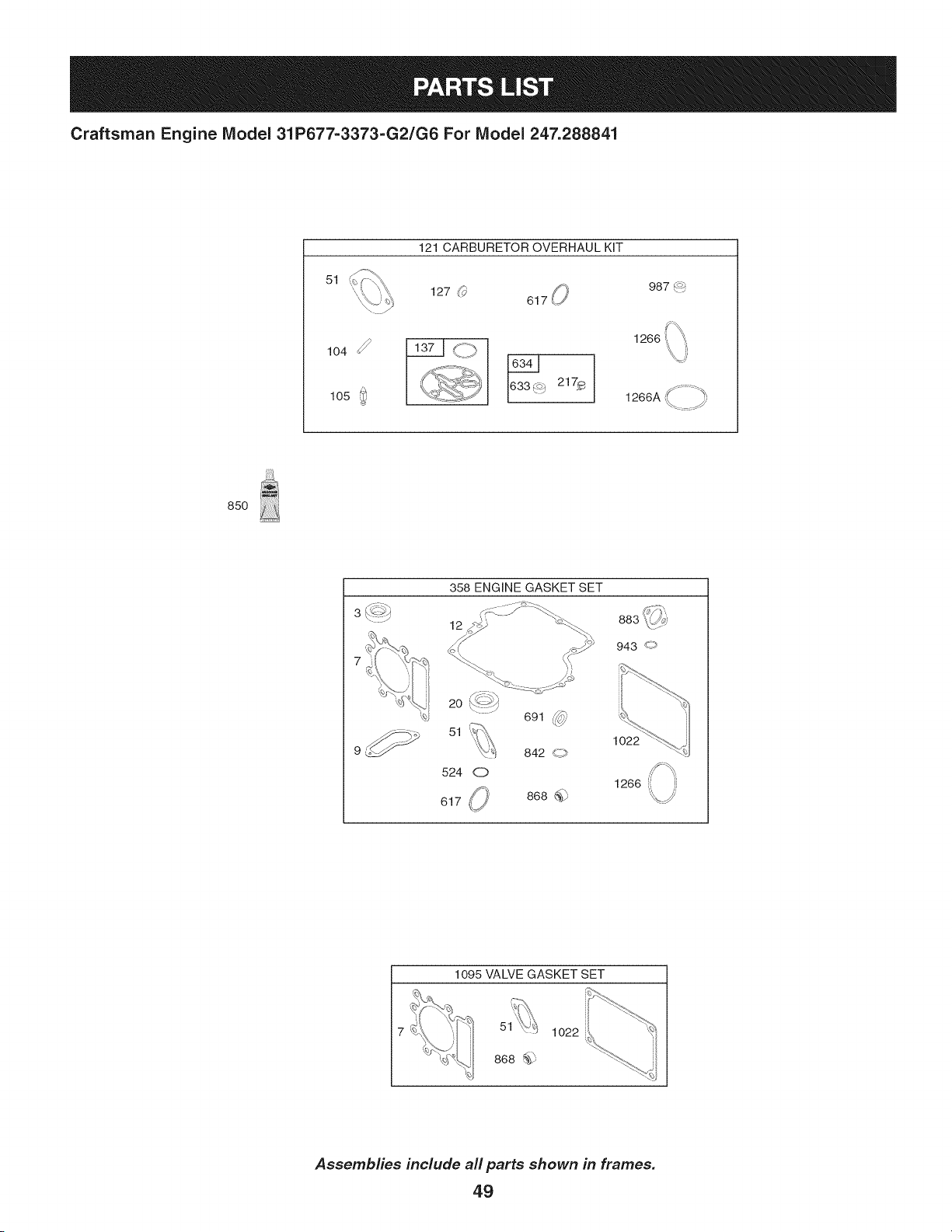
Craftsman Engine Model 31P677-3373-G2/G6 For Model 247.288841
51
104
105
121 CARBURETOR OVERHAUL KIT
127 (_'
S_ _
987('_
1266
85O
358 ENGINE GASKET SET
12
883 _¢_j
943 <)
20 L'_->>
\ -
691 (_j_)
al ,Tii).
'_) 842 _
524 O
,/_ 868 @
617 (_'
1022
1266
1095 VALVE GASKET SET
51 1022
868 _
Assemblies include all parts shown in frames.
49

Craftsman Engine IViodel 31P677=3373=G2/G6 For IViodel 247.288841
Ref,
NO,
1 796010
2 399265
3 391086s
4 697188
5 796026
7 796584
11 794683
12 697110
13 793988
15 690946
16 797759
20 795387
22 692125
23 698281
24 796335
25 796172
796173
26 791936
792649
27 698469
28 796007
29 794122
32 791118
33 792868
34 791935
35 691279
36 691279
37 697352
42 499586
43 691968
45 690564
46 793880
48 N/A
50 796180
51 692137
51A 796081
53 690227
54 691148
78 691693
94 793610
95 690718
98 695408
Part No. Description
CylinderAssembly
Kit-Bushing/Seal(MagnetoSide)
Seal-Oil (MagnetoSide)
Sump-Engine
Head-Cylinder
Gasket-CylinderHead
Tube-Breather
Gasket-Crankcase
Screw(Cylinder Head)
Plug-OilDrain
Crankshaft
Seal-Oil (PTOSide)
Screw(CrankcaseCover/Sump)
Flywheel
Key-Flywheel(Steel)
PistonAssembly(Standard)
PistonAssembly(.020"Oversize)
Ring Set(Standard)
Ring Set(.020" Oversize)
Lock-PistonPin
Pin-Piston
Rod-Connecting
Screw(ConnectingRod)
Valve-Exhaust
Valve-Intake
Spring-Valve(Intake)
Spring-Valve(Exhaust)
Guard-Flywheel
Keeper-Valve
Slinger-Governor/Oil
Tappet-Valve
Camshaft
ShortBlock (NotAvailableAt This Printing)
Manifold-Intake
Gasket-Intake
Gasket-Intake
Stud (Carburetor)
Screw(IntakeManifold)
Screw(FlywheelGuard)
Kit-Nle Mixture
Screw(ThrottleValve)
Kit-Nle Speed
50
I
Ref,
I Part No,
No,
I
104 694918
105 696136
108 695419
117 699773
118 843099
121 796184
125 796110
127 690727
130 792747
131 792765
133 694914
135 698780
135A 792022
137 698781
141 792777
146 691639
186 794873
187 791805
188 691693
192 691986
202 691841
209 692208
216 691840
217 695409
222 694042
227 691374
232 691842
238 691843
240 394358s
265 691024
267 794904
276 695410
304 797900
305 697102
305A 793376
305B 795891
305C 799370
Description
Pin-FloatHinge
Valve-FloatNeedle
Valve-Choke
Jet-Main(Standard)
Jet-Main(HighAltitude)
Kit-CarburetorOverhaul
Carburetor(ServiceCarburetor)
Plug-Welch
Valve-Throttle
Kit-ThrottleShaft
Float-Carburetor
Tube-FuelTransfer(OriginalCarburetor)
Tube-FuelTransfer(ServiceCarburetor)
Gasket-FloatBowl
Kit-ChokeShaft
Key-Timing
Connector-Hose(IntakeManifold)
Line-Fuel(Formed)(Cutto RequiredLength)
Screw(ControlBracket)
Adjuster-RockerArm
Link-MechanicalGovernor
Spring-Governor(Green)
Link-Governor
Spring-ChokeReturn
Bracket-Control
Lever-GovernorControl
Spring-GovernorLink
Cap-Valve
Filter-Fuel
Clamp-Casing
Screw(CasingClamp)
Washer-Sealing
Housing-Blower
Screw(BlowerHousing)(BlowerHousingto
Cylinder)(1/4-20xl.14)
Screw(BlowerHousing)(1/4-20x.68)
Screw(BlowerHousing)(ToCarburetorElbow)
(#10-16x.43)
Screw(BlowerHousing)(After DateCode:
10120500)(1/4-20x.90)
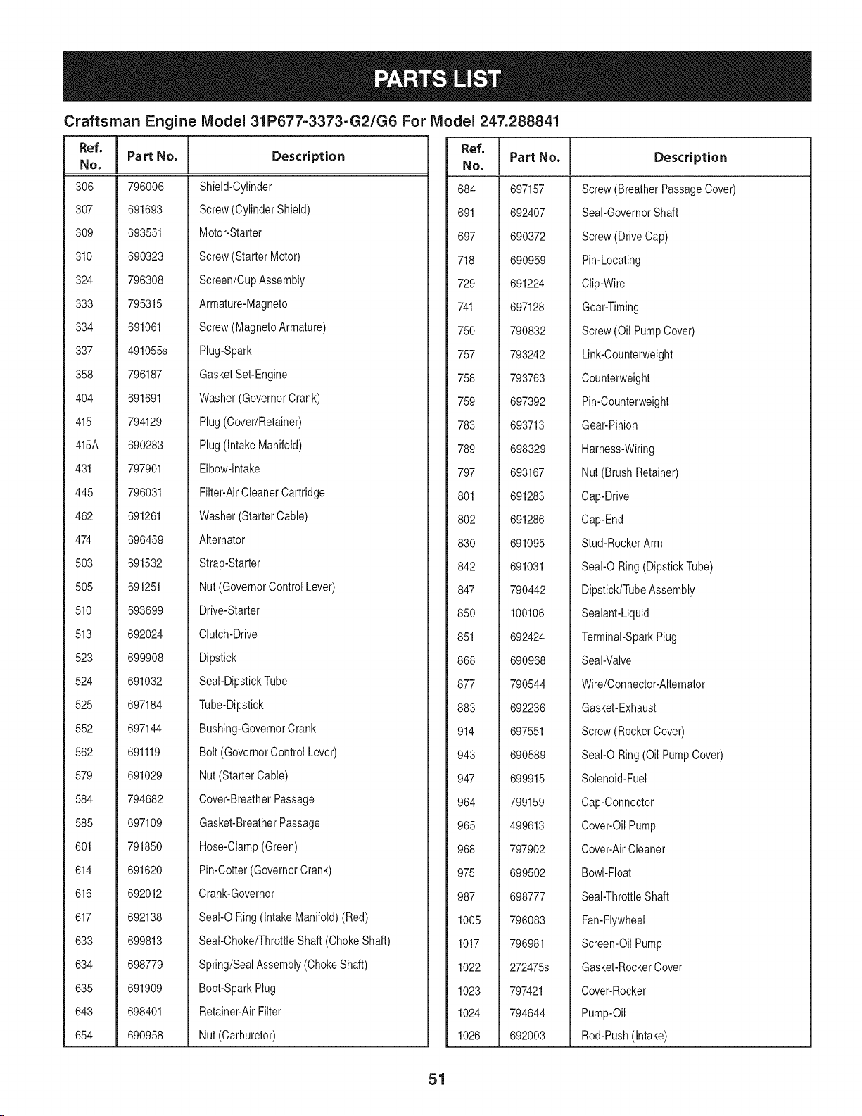
Craftsman Engine IViodel 31P677=3373=G2/G6 For IViodel 247.288841
I
Ref.
I Part No.
No,
I
306 796006
307 691693
309 693551
310 690323
324 796308
333 795315
334 691061
337 491055s
358 796187
404 691691
415 794129
415A 690283
431 797901
445 796031
462 691261
474 696459
503 691532
505 691251
510 693699
513 692024
523 699908
524 691032
525 697184
552 697144
562 691119
579 691029
584 794682
585 697109
601 791850
614 691620
616 692012
617 692138
633 699813
634 698779
635 691909
643 698401
654 690958
Description
Shield-Cylinder
Screw(CylinderShield)
Motor-Starter
Screw(Starter Motor)
Screen/CupAssembly
Armature-Magneto
Screw(MagnetoArmature)
Plug-Spark
GasketSet-Engine
Washer(GovernorCrank)
Plug(Cover/Retainer)
Plug(IntakeManifold)
Elbow-Intake
Filter-AirCleanerCartridge
Washer(StarterCable)
Alternator
Strap-Starter
Nut (GovernorControlLever)
Drive-Starter
Clutch-Drive
Dipstick
Seal-DipstickTube
Tube-Dipstick
Bushing-GovernorCrank
Bolt (GovernorControlLever)
Nut (StarterCable)
Cover-BreatherPassage
Gasket-BreatherPassage
Hose-Clamp(Green)
Pin-Cotter(GovernorCrank)
Crank-Governor
Seal-O Ring(IntakeManifold)(Red)
Seal-Choke/ThrottleShaft (ChokeShaft)
Spring/SealAssembly(ChokeShaft)
Boot-SparkPlug
Retainer-AirFilter
Nut (Carburetor)
Ref.
NO,
684 697157
691 692407
697 690372
718 690959
729 691224
741 697128
750 790832
757 793242
758 793763
759 697392
783 693713
789 698329
797 693167
801 691283
802 691286
830 691095
842 691031
847 790442
850 100106
851 692424
868 690968
877 790544
883 692236
914 697551
943 690589
947 699915
964 799159
965 499613
968 797902
975 699502
987 698777
1005 796083
1017 796981
1022 272475s
1023 797421
1024 794644
1026 692003
Part No, Description
Screw(BreatherPassageCover)
Seal-GovernorShaft
Screw(DriveCap)
Pin-Locating
Clip-Wire
Gear-Timing
Screw(Oil PumpCover)
Link-Counterweight
Counterweight
Pin-Counterweight
Gear-Pinion
Harness-Wiring
Nut(Brush Retainer)
Cap-Drive
Cap-End
Stud-RockerArm
Seal-O Ring(DipstickTube)
Dipstick/TubeAssembly
Sealant-Liquid
Terminal-SparkPlug
Seal-Valve
Wire/Connector-Alternator
Gasket-Exhaust
Screw(RockerCover)
Seal-O Ring(Oil PumpCover)
Solenoid-Fuel
Cap-Connector
Cover-OilPump
Cover-AirCleaner
Bowl-Float
Seal-ThrottleShaft
Fan-Flywheel
Screen-OilPump
Gasket-RockerCover
Cover-Rocker
Pump-Oil
Rod-Push(Intake)
51

Craftsman Engine IViodel 31P677=3373=G2/G6 For IViodel 247.288841
Ref, I
No,
1026A
1027
1029
1034
1036
Part No. Description
692011
492932s
691751
690822
699852
698139
691265
280275
276344
698516
690363
691293
691333
794152
691183
695407
697124
697104
691917
793243
Rod-Push(Exhaust)
Filter-Oil
Arm-Rocker
Guide-PushRod
Label-Emissions(Availablefroma Briggs&
StrattonAuthorizedDealer)
Plate-Trim
Screw(Flywheel)
Ring-Retaining
Tie-Cable
Operator'sManual
Kit-Screw/Washer(Alternator)
Screw(FlywheelFan)
Retainer-Brush
Cap-Limiter
GasketSet-Valve
Screw(Alternator)
Screw(FloatBowl)
Reed-Breather
Screw(BreatherReed)
Seal-O Ring(IntakeElbow)(Red)
Plug-AVSCounterweight
1040
1044
1051
1054
1058
1059
1070
1090
1091
1095
1119
1127
1263
1264
1266
1270
1329 31P677-3373-G2/G6 ReplacementEngine
1330 276781 RepairManual
EngineGasketSet KeyNo. 358
ValveGasketSet KeyNo. 1095
CarburetorOverhaulKit KeyNo. 121
52

This page intentionally left blank. Use this page to make any notes regarding your tractor.
53
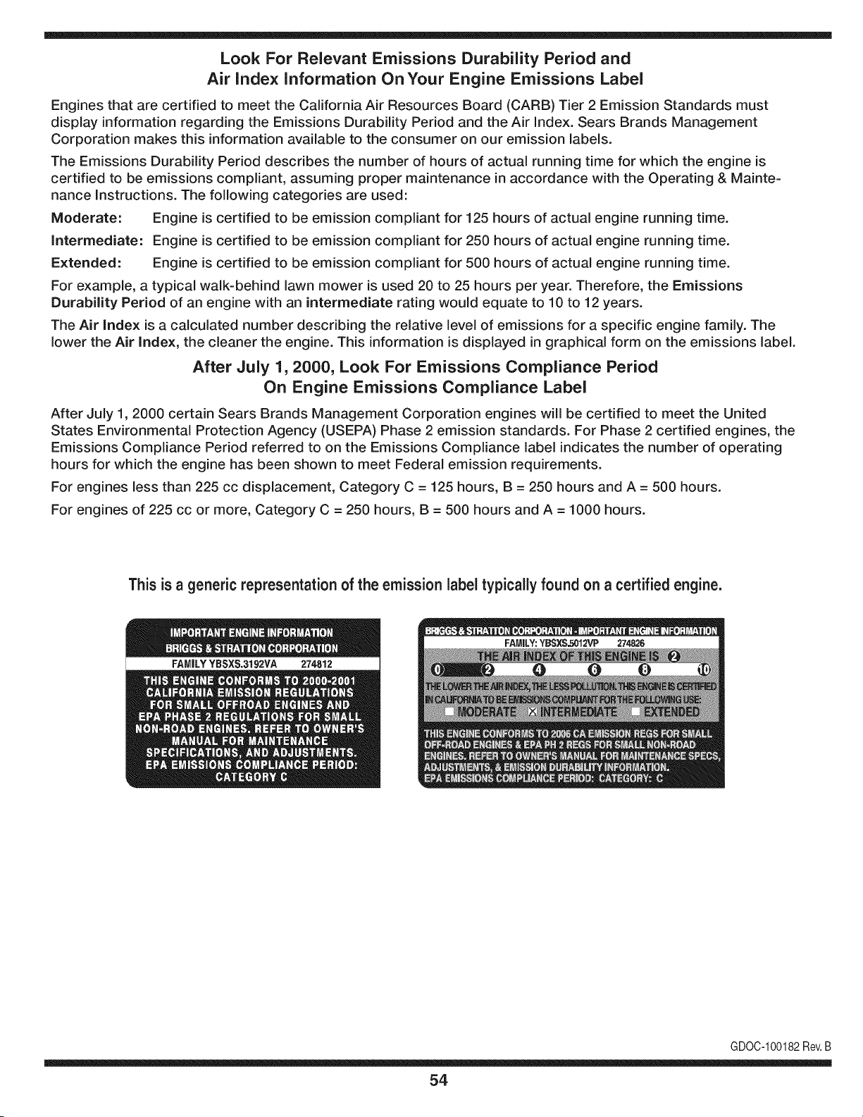
Look For Relevant Emissions Durability Period and
Air index information On Your Engine Emissions Label
Engines that are certified to meet the California Air Resources Board (CARB) Tier 2 Emission Standards must
display information regarding the Emissions Durability Period and the Air Index. Sears Brands Management
Corporation makes this information available to the consumer on our emission labels.
The Emissions Durability Period describes the number of hours of actual running time for which the engine is
certified to be emissions compliant, assuming proper maintenance in accordance with the Operating & Mainte-
nance Instructions. The following categories are used:
Moderate: Engine is certified to be emission compliant for 125 hours of actual engine running time.
Intermediate: Engine is certified to be emission compliant for 250 hours of actual engine running time.
Extended: Engine is certified to be emission compliant for 500 hours of actual engine running time.
For example, a typical walk-behind lawn mower is used 20 to 25 hours per year. Therefore, the Emissions
Durability Period of an engine with an intermediate rating would equate to 10 to 12 years.
The Air index is a calculated number describing the relative level of emissions for a specific engine family. The
lower the Air Index, the cleaner the engine. This information is displayed in graphical form on the emissions label.
After July 1,2000, Look For Emissions Compliance Period
On Engine Emissions Compliance Label
After July 1, 2000 certain Sears Brands Management Corporation engines will be certified to meet the United
States Environmental Protection Agency (USEPA) Phase 2 emission standards. For Phase 2 certified engines, the
Emissions Compliance Period referred to on the Emissions Compliance label indicates the number of operating
hours for which the engine has been shown to meet Federal emission requirements.
For engines less than 225 cc displacement, Category C = 125 hours, B = 250 hours and A = 500 hours.
For engines of 225 cc or more, Category C = 250 hours, B = 500 hours and A = 1000 hours.
This is a generic representation of the emission label typically found on a certified engine.
FAMILYYBSXS.3192VA 274812
GDOC-100182Rev.B
54
(Thispageapplicableinthe U.S.A.and Canadaonly.)
Sears Brands Management Corporation (Sears), the California Air Resources Board (CARD)
and the United States Environmental Protection Agency (U.S. EPA)
Emission Control System Warranty Statement (Owner's Defect Warranty Rights and Obligations)
EMISSIONCONTROLWARRANTYCOVERAGEISAPPLICABLETOCERTI-
FIEDENGINESPURCHASEDIN CALIFORNIAIN 1995ANDTHEREAF-
TER,WHICHARE USEDINCALIFORNIA,ANDTOCERTIFIEDMODEL
California and United States Emission
The CaliforniaAir ResourcesBoard(CARD),U.S.EPAand Searsare pleased
to explainthe EmissionControlSystemWarrantyon your modelyear2000and
latersmalloff-roadengine(SORE).InCalifornia,newsmall off-roadengines
mustbe designed,builtand equippedto meettheState'sstringentanti-smog
standards.Elsewherein the UnitedStates,newnon-road,spark-ignition
enginescertifiedfor modelyear 1997and latermustmeetsimilarstandardsset
forth bythe U.S.EPA.Sears mustwarrantthe emissioncontrol systemon your
YEAR 1997AND LATERENGINESWHICHARE PURCHASEDAND USED
ELSEWHEREIN THEUNITEDSTATES(ANDAFTERJANUARY1,2001 IN
CANADA).
Control Defects Warranty Statement
enginefor theperiodsoftime listedbelow,providedtherehas been noabuse,
neglector impropermaintenanceof your smalloff-roadengine.Youremis-
sion controlsystemincludespartssuch as the carburetor,air cleaner,ignition
system,mufflerand catalyticconverter.Also includedmaybe connectorsand
otheremissionrelatedassemblies.Wherea warrantableconditionexists,Sears
will repairyour smalloff-roadengineat nocostto you includingdiagnosis,parts
and labor.
Sears Emission Control Defects Warranty Coverage
Smalloff-roadenginesarewarrantedrelativeto emissioncontrol partsdefects
fora periodof one year,subjectto provisionsset forth below.Ifany covered
Owner's Warranty
Asthe smalloff-roadengine owner,you are responsiblefor theperformanceof
therequiredmaintenancelistedin yourOperatingand MaintenanceInstruc-
tions.Searsrecommendsthatyou retain allyourreceiptscoveringmaintenance
on yoursmalloff-roadengine,butSears cannotdenywarrantysolelyfor the
lackof receiptsor for yourfailureto ensuretheperformanceof allscheduled
maintenance.As the smalloff-roadengineowner,you shouldhoweverbe
awarethat Searsmay denyyou warrantycoverageif your smalloff-roadengine
ora part hasfailed dueto abuse,neglect,impropermaintenanceor unap-
parton yourengineis defective,the part willbe repairedorreplacedbySears.
Responsibilities
provedmodifications.Youare responsiblefor presentingyour smalloff-road
engineto an AuthorizedSearsServiceDealeras soonas a problemexists.The
undisputedwarrantyrepairsshouldbe completedina reasonableamountof
time,not to exceed30 days.Ifyou haveany questionsregardingyourwarranty
rightsand responsibilities,you shouldcontacta SearsService Representative
at 1-800-469-4663.The emissionwarrantyis a defectswarranty.Defectsare
judgedon normalengineperformance.Thewarrantyis notrelatedto an in-use
emissiontest.
Sears Emission Control Defects Warranty Provisions
ThefollowingarespecificprovisionsrelativetoyourEmissionControlDefectsWarrantyCoverage.ItisinadditiontotheSearsenginewarrantyfornon-regulated
enginesfound in theOperatingand MaintenanceInstructions.
1. WarrantedParts
Coverageunderthis warrantyextendsonly to the parts listedbelow (the
emissioncontrolsystemsparts)to the extentthese partswere presenton
the engine purchased.
a. FuelMeteringSystem
• Cold start enrichmentsystem
• Carburetorand internalparts
• FuelPump
b. Air lnduction System
• Air cleaner
• Intakemanifold
c. IgnitionSystem
• Spark plug(s)
• Magnetoignitionsystem
d. CatalystSystem
• Catalyticconverter
• Exhaustmanifold
• Air injectionsystemor pulsevalve
e. MiscellaneousItemsUsedin AboveSystems
• Vacuum,temperature,position,timesensitivevalves
andswitches
• Connectorsandassemblies
2. Lengthof Coverage
Searswarrantsto the initialownerand eachsubsequentpurchaserthat
the WarrantedParts shallbe free fromdefects in materialsandworkman-
shipwhich causedthefailure of the WarrantedPartsfor a periodof one
yearfromthe datethe engineis deliveredto a retailpurchaser.
3. NoCharge
Repairor replacementof anyWarrantedPartwill be performedat no
chargeto the owner,includingdiagnosticlabor whichleadsto the
determinationthata WarrantedPartis defective,if the diagnosticwork is
performedat an AuthorizedSearsServiceDealer.Foremissionswarranty
servicecontact yournearestAuthorizedSears ServiceDealeras listed in
the "YellowPages"under"Engines,Gasoline,""GasolineEngines,""Lawn
Mowers,"or similarcategory.
4. Claimsand CoverageExclusions
Warrantyclaimsshall be filed in accordancewiththe provisionsof the
Sears EngineWarrantyPolicy.Warrantycoverageshall be excludedfor
failuresof WarrantedPartswhichare notoriginal Sears partsor because
of abuse, neglector impropermaintenanceas setforth inthe Sears
EngineWarrantyPolicy.Sears is notliableto coverfailuresof Warranted
Partscausedby theuse of add-on,non-original,or modifiedparts.
5. Maintenance
Any WarrantedPart whichis notscheduledfor replacementas required
maintenanceor whichis scheduledonly for regularinspectionto the effect
of "repairor replaceas necessary"shallbe warrantedasto defectsfor the
warrantyperiod.Any WarrantedPartwhich is scheduledfor replacement
as requiredmaintenanceshallbe warrantedasto defectsonly forthe
periodof time up to the first scheduledreplacementfor that part. Any
replacementpart that is equivalentin performanceand durabilitymay
be usedin the performanceof anymaintenanceor repairs.The owneris
responsibleforthe performanceof all requiredmaintenance,as definedin
the SearsOperatingand MaintenanceInstructions.
6. ConsequentialCoverage
Coveragehereundershallextend to thefailure of any enginecomponents
caused bythe failureof any WarrantedPartstill underwarranty.
Inthe USAandCanada,a 24 hour hotline, 1-800-469-4663,has a menu of pre-recordedmessagesofferingyou enginemaintenanceinformation.
GD0C-100188Rev.B
55
FEDERAL and/or CALIFORNIA EMISSION CONTROL WARRANTY STATEMENT
YOUR WARRANTY RIGHTS AND OBLIGATIONS
MTDConsumerGroupInc,the UnitedStatesEnvironmentalProtectionAgency (EPA),and, forthose productscertifiedfor sale in the stateof California,the
CaliforniaAir ResourcesBoard(CARB)are pleasedto explainthe emission(evaporativeand/or exhaust)controlsystem(ECS) warrantyon youroutdoor 2006
andlater smalloff-roadspark-ignitedengine andequipment(outdoorequipmentengine)In California,new outdoorequipmentengines mustbe designed,built and
equippedto meetthe State'sstringentanti-smog standards(inotherstates, 1997andlater modelyear equipmentmustbe designed,built, and equippedto meet
theU.S. EPAsmalloff-road, sparkignitionengine regulations.MTDConsumerGroupInc mustwarrantthe ECSon your outdoorequipmentenginefor the period of
timelisted belowprovidedtherehas been no abuse,neglector impropermaintenanceof outdoorequipmentengine.
Your ECSmayincludeparts such as the carburetor,fuel-injectionsystem,the ignitionsystem,catalyticconverter,fuel tanks,fuel lines,fuelcaps, valves,canisters,
filters,vapor hoses,clamps,connectors,andotherassociatedemission-relatedcomponents.
Wherea warrantableconditionexists, MTDConsumerGroupIncwill repairyouroutdoorequipmentengine at no cost to you includingdiagnosis,parts and labor.
MAN UFACTURER'S WARRANTY COVERAGE:
Thisemissioncontrolsystemis warrantedfor two years. If any emission-relatedpart on your outdoorequipmentengine is defective,the part will be repairedor
replacedby MTDCONSUMERGROUPINC.
OWNER'S WARRANTY RESPONSIBILITIES:
Asthe outdoorequipmentengineowner,you are responsiblefor performanceof the requiredmaintenancelisted inyour owner'smanual.MTDConsumerGroup
Inc recommendsthat you retainall receiptscoveringmaintenanceon youroutdoorequipmentengine,butMTDConsumerGroupInc cannotdeny warrantysolely
forthe lackof receipts.
Asthe outdoorequipmentengineowner,you shouldhoweverbe awarethat MTDConsumerGroupInc may denyyou warrantycoverageifyour outdoorequipment
engineor a part has faileddue to abuse, neglect,or impropermaintenanceor unapprovedmodifications.
Youare responsiblefor presentingyouroutdoor equipmentengineto MTDConsumerGroupInc'sdistributioncenteror servicecenteras soon asthe problem
exists.The warrantyrepairsshouldbe completedin a reasonableamountof time, notto exceed30 days.If you havea questionregardingyour warrantycoverage,
you shouldcontactthe MTDConsumerGroupIncService Departmentat 1-800-800-7310orvia emailat http://support.mtdproducts.com
GENERAL EMISSIONS WARRANTY COVERAGE:
MTDConsumerGroupIncwarrantsto the ultimatepurchaserand eachsubsequentpurchaserthat theoutdoor equipmentengine is: Designed,built and equipped
so asto conformwithall applicableregulations;and freefromdefects in materialsand workmanshipthatcausethe failureof a warrantedpart to be identicalin all
materialrespectsto that part as describedin MTDConsumerGroup Inc'sapplicationfor certification.
The warrantyperiodbeginson thedate theoutdoor equipmentengine is deliveredto an ultimatepurchaseror first placedintoservice.The warrantyperiodis two
years.
Subjectto certainconditionsand exclusionsasstated below,the warrantyonemission-relatedparts is asfollows:
1. Any warrantedpart that is notscheduledfor replacementas requiredmaintenancein thewritten instructionssupplied, is warrantedforthe warrantyperiod
statedabove. Ifthe part fails duringthe periodof warrantycoverage,thepart will be repairedor replacedbyMTDConsumerGroupInc accordingto subsection
(4) below.Anysuchpart repairedor replacedunderwarrantywillbe warrantedfor the remainderof the period.
2. Any warrantedpart that is scheduledonly for regularinspectionin the writteninstructionssupplied is warrantedforthe warrantyperiodstatedabove.Any such
part repairedor replacedunderwarrantywill be warrantedforthe remainingwarrantyperiod.
3. Any warrantedpart that is scheduledfor replacementas requiredmaintenancein thewritten instructionssuppliedis warrantedfor the periodof timebeforethe
first scheduledreplacementdatefor that part. If the partfails beforethefirst scheduledreplacement,the part will be repairedor replacedby MTDConsumer
GroupInc accordingto subsection(4) below.Anysuch part repairedor replacedunderwarrantywill be warrantedfor the remainderof the periodprior to the
first scheduledreplacementpointfor the part.
4. Repairor replacementof anywarrantedpart underthe warrantyprovisionshereinmustbe performedat a warrantystationat no chargeto the owner.
5. Notwithstandingthe provisionsherein,warrantyservicesor repairswill beprovidedat all of our distributioncentersthatare franchisedto servicethe subject
enginesor equipment.
6. The outdoorequipmentengine ownerwill notbe chargedfor diagnostic laborthat is directlyassociatedwithdiagnosisof a defective,emission-relatedwar-
rantedpart, providedthat suchdiagnosticwork is performedat a warrantystation.
7. MTDConsumerGroupInc is liablefor damagesto otherengine or equipmentcomponentsproximatelycausedby a failure underwarrantyof any warranted
part.
8. Throughoutthe off-roadengineand equipmentwarrantyperiodstatedabove, MTDConsumerGroupInc will maintaina supplyof warrantedparts sufficientto
meetthe expecteddemandfor such parts.
9. Any replacementpart maybe usedinthe performanceof any warrantymaintenanceor repairsand mustbe providedwithoutchargeto the owner.Suchuse will
notreducethe warrantyobligationsof MTDConsumerGroupInc.
10.Add-onor modifiedpartsthat are notexemptedbythe Air ResourcesBoardmaynot beused.The use of any non-exemptedadd-on or modifiedparts by the
ultimatepurchaserwill be groundsfor disallowinga warrantyclaims. MTDConsumerGroup Incwill not be liableto warrantfailuresof warrantedparts caused
bythe use of a non-exemptedadd-onor modifiedpart.
WARRANTED PARTS:
The repairor replacementof anywarrantedpart otherwiseeligiblefor warrantycoveragemaybe excludedfrom suchwarrantycoverageif MTDConsumerGroup
Inc demonstratesthatthe outdoorequipmentenginehas beenabused,neglected,or improperlymaintained,and thatsuch abuse, neglect,or impropermainte-
nancewasthe direct causeof the needfor repairor replacementof the part. Thatnotwithstanding,anyadjustmentof a componentthat hasa factory installed,
andproperlyoperating,adjustmentlimitingdevice is still eligible for warrantycoverage.Further,the coverageunderthis warrantyextendsonly to partsthat were
presentonthe off-roadengineand equipmentpurchased.
Thefollowing emissionwarrantypartsare covered(if applicable):
(1) FuelMeteringSystem
• Cold start enrichmentsystem(softchoke)
• Carburetorand internalparts (or fuel injectionsystem)
• Fuelpump
• Fueltank
(2) Air InductionSystem
• Air cleaner
• Intakemanifold
(3) IgnitionSystem
• Sparkplug(s)
• Magnetoignitionsystem
(4) ExhaustSystem
• Catalyticconverter
• SAI(Reed valve)
(5) MiscellaneousItemsUsedin AboveSystem
• Vacuum,temperature,position,timesensitivevalvesand switches
• Connectorsandassemblies
(6) EvaporativeControl
• Fuelhose
• Fuelhoseclamps
• Tetheredfuel cap
• Carboncanister
• Vapor lines
GDOC-100223Rev.A
Congratulationson makinga smartpurchase.YournewCraftsman@
productis designedandmanufacturedfor yearsof dependableopera-
tion.But likeall products,it may requirerepairfromtime to time.That's
whenhavinga RepairProtectionAgreementcansaveyoumoneyand
aggravation.
Here'swhat the RepairProtectionAgreement*includes:
* Expert service byour 10,000professionalrepairspecialists
o Unlimitedserviceand no chargefor partsand laboron all
coveredrepairs
o Product replacementup to $1500if yourcoveredproductcan't be
fixed
• Discountof 10%from regularprice of serviceand relatedinstalled
partsnotcoveredby theagreement;also,10%off regularpriceof
preventivemaintenancecheck
• Fast help by phone- we call it RapidResolution- phonesupport
froma Searsrepresentative.Thinkof usas a "talkingowner's
manual."
Onceyou purchasethe Agreement,a simplephonecall is all thatit
takesfor youto scheduleservice.Youcan call anytimedayor night,or
schedulea serviceappointmentonline.
The RepairProtectionAgreementis a risk-freepurchase.If youcancel
for any reasonduringthe productwarrantyperiod,wewill provideafull
refund.Or,a proratedrefundanytimeafter the productwarrantyperiod
expires.Purchaseyour RepairProtectionAgreementtoday!
Somelimitationsand exclusionsapply. For pricesand additional
informationin the U.S.A. call 1-800-827-6655.
*Coverage in Canadavaries on some items.Forfull details call
Sears Canadaat 1-800-361-6665.
Sears Installation Service
ForSearsprofessionalinstallationof homeappliances,garagedoor
openers,waterheaters,andothermajorhomeitems,in the U.S.A.or
Canadacall 1-800-4-MY-HOME®.
58
Operacion segura Practicas .......... Paginas 59
Etiquetas De Seguridad ................ Page 65
Asamblea ........................... Page 66
Operacion de ...................... Paginas 68
De Servicio y Mantenimiento de ....... Paginas 75
Fuera de temporada de almacenamiento .. Page 85
Soluci6n de problemas ................ Page 86
Lista de piezas ..................... Paginas 30
Reparaci6n de Acuerdo de Proteccion .... Page 91
Servicio de nOmeros ............ atrasados Page
CRAFTSMAN GARANT{A TOTAL
PORDOSANOSa partirdelafechadecornpra,todaslaspartesno fungiblesde esteequipode equitaci6nest_ngarantizadoscontracualquierdefectode
materialo rnanodeobra.Unapiezadefectuosanofungiblesrecibir_.nreparaci6ngratuitaen elhogaro lasustituci6nsi lareparaci6nes irnposible.
Durantecincoa_osdesdelafechadecornpra,el ejedelmarcoy elfrentedeesteequipode equitaci6nest_ngarantizadoscontracualquierdefectode
materialornanode obra.Uncuadrodefectuosoo ejedelanterorecibir_reparacbngratuitaenelhogarolasustitucbnsila reparacbnesirnposible.
POR90 D{ASa partrdela fechadecornpra,la bateria(unapartefungibles)deesteequipodeequitaci6nest_garantizadacontracualquierdefectode
materialornanode obra(nuestraspruebasdernuestraquenornantienelacarga).Unabateriadefectuosarecibir_,reernplazogratuitoenel hogar.
ADICIONALDEGARANT{ALIMITADADEPORVIDAen FUNDICIONejedelantero(si est;_instalado)
PARASIEMPREY COMOSEUTILIZAporelpropietariooriginaldespuesdelquintoa_odesdelafechadecornpra,elhierrofundidoejedelantero(siexiste)
deesteequipodeequitaci6nest_garantizadacontracualquierdefectode materialo rnanodeobra.Conelcornprobantedecornpra,unejedelanterofundido
defectuosorecibirAreernplazogratuitoenelhogar.
GARANT{ADESERViClO
Paraobtenerinformaci6ndetaladacoberturadelagarantaparaobtenerlareparaci6no sustituci6ngratuita,lameal 1-800-659-5917ovisiteel sitioweb:
www.craftsrnan.corn
Entodosloscasosanteriores,si lareparacbno reernplazodeunapartees irnposible,elequipodeequitaci6nset&reernplazadode formagratuitaconel
rnisrnoo equivalente.
Todoslosdelacoberturadelagarantaanteriores inv_.lidasiesteequipode rnontara cabaloesutilzadoalgunavez,rnientrasquelaprestaci6ndeservicios
cornercialesosisealqulaaotrapersona.
Estagarantiacubrelos defectosSOLOde materialesyfabricacibn.Lagarantianoincluye:
• Laspartesconsurnibles(exceptola bateria)quepuedegastarseporelusonormaldentrodelperiodode garanta,incluyendoperono lrnitadoa,cuchilas,
bujias,fltrosdeaire,correasyfltrosdeaceite.
• Losserviciosdernantenirniento,carnbiosdeaceite,o puestasapunto.
•Tireel reernplazoo reparaci6ndepinchazoscausadospotobjetosextemos,talescornoclavos,espinas,toconeso vidrio.
•Tirede laruedao el reernplazoo lareparaci6nresultantesdeldesgastenormal,accidenteornalfuncionarnientoo rnantenirniento.
• Lasreparacionesnecesariasdebidoalabusodeloperador,incluyendoperonolrnitadoalosdaSoscausadosporelrernolquedelosobjetosrn_.sall_.dela
capacidaddelequipodeequitacbn,el irnpactodeobjetosquedoblenla estructura,elrnontajedelejeodelcigieSal,odeexcesode velocidaddelmotor.
• Lasreparacionesnecesariasdebidoa laneglgenciadeloperador,incluyendoperonoIrnitadoa,daios el_ctricosy rnecanicoscausadospotunalrnace-
narnientoinadecuado,no utilzaci6ndelacaldado cantidadde aceitedemotor,nornantenerel pisolbrederesiduosinlarnables,ofaltadernantenirniento
delEquipoecuestredeacuerdoalas instruccionescontenidasenelmanualdeloperador.
• Elmotor(sisternade combustible)delrnpiezao reparacionesprovocadasporuncombustiblequesecontarninadouoxidado(viejo).Engeneral,el
combustibledebeset utlizadodentrodelos30diassiguientesala fechadecornpra.
•deterioroy desgastenormalde losacabadosexteriores,o reernplazodelaetiquetadelproducto.
Estagarantaleotorgaderechoslegalesespecificos,y ustedtarnbi_npuedetenetotrosderechosquevariandeestadoaestado.
SearsBrandsManagementCorporation,HoffmanEstates,IL60179
Aceitedel motor: SAE30
Combustible: Gasolna sinplorno
Bujia: Champion®RC12YC
Motor: Briggs& Stratton
N_mero de modelo ..........................................................
N_mero de serie ..............................................................
Fechade compra .............................................................
RegistrearribaelnQmerodelmodelo,elnQmerodeserieylafechadecompra
© SearsBrands,LLC
59
Lapresenciade estesirnboloindicaque setratade instrucciones
irnportantesde seguridadque se deben respetarpara evitar
ponerenpeligrosu seguridadpersonaly/o materialy lade otras
personas.Leay sigatodaslasinstruccionesdeestemanualantes
de poneren funcionarnientoestarn_.quina.Si no respetaestas
instruccionespodria provocarlesionespersonales.Cuandoveaeste
sirnbolo,i presteatenci6na la advertencia!
PROPOSICION 65 DE CALIFORNIA
Elescapedel motorde esteproducto,algunosde suscornponentes
y algunoscornponentesdel vehiculocontieneno liberansustancias
quirnicasqueel estadode Californiaconsideraque puedenproducir
c_.ncer,defectosde nacirnientou otrosproblernasreproductivos.
Losbornesdela bateriay losaccesoriosdines contienenplornoy
cornpuestosde plorno,sustanciasquirnicasquesegQnIoestableci-
do pot el Estadode Californiacausanc_.ncery da_osen el sisterna
reproductivo.Ldveselas manos despu_sde estar en contacto
con estoscomponentes.
Estarn_.quinarueconstruidapara seroperadadeacuerdocon
las reglasde seguridadcontenidasenestemanual.AI igualque
concualquiertipo deequipo rnotorizado,undescuidoo errorpor
partedeloperadorpuedeproducirlesionesgraves.Estarn_.quina
es capazde arnputarrnanosy piesy dearrojarobjetoscon gran
fuerza.De norespetarlas instruccionesde seguridadsiguientesse
puedenproducirlesionesgraveso la rnuerte.
Su responsabilidad--Restrinja el usode esta rn_.quina
rnotorizadaalas personasque lean,cornprendany respetenlas
advertenciase instruccionesqueaparecenen estemanualyen la
rn_.quina.
iGUARI)E ESTASINSTRUCCIONES!
FUNCIONAMIENTO GENERAL
• Lea,entienday curnplatodaslas instruccionesincluidasen
la rn_.quinayen los rnanualesantesde rnontarlay utilizarla.
Guardeestemanualenun lugarseguropara consultasfuturasy
peri6dicas,asi cornoparasolicitarrepuestos.
• Farniliaricesecontodos los controlesy con el usoadecuado
de losrnisrnos.Sepac6rnodetenerla rn_.quinay desactivarlos
controlesr_.pidarnente.
• No perrnitanuncaque losni_os rnenoresde 14a_osutilicen
estarn_.quina.Los ni_osde 14a_osen adelantedebenleery
entenderlas instruccionesde operaci6ny norrnasdeseguridad
contenidasen estemanual,yen la rn_.quinay debenser
entrenadosy supervisadosporun adulto.
• Nuncaperrnitaque los adultosoperenesta rn_.quinasin recibir
antesla instrucci6napropiada.
• Paraayudara evitarelcontactocon las cuchillaso unalesi6npor
algQnobjetoqueseaarrojado,rnantengaa los observadores,a
los ayudantes,ni_osy rnascotasalejadosal rnenos25 metrosde
la rn_.quinarnientrasest,. en funcionarniento.Detengala rn_.quina
si alguienentraen la zona.
• Inspeccionerninuciosarnenteel Areadondeutilizar_,el equipo.
Retiretodaslas piedras,palos,cables,huesos,juguetesy otros
objetosextra_osquepodrianser recogidosy arrojadosporla
acci6nde lascuchillas.Losobjetosarrojadosporla rn_.quina
puedenproducirlesionesgraves.
• Planifiqueel patr6nde corte delc_spedque ha deseguirpara
evitarla descargade materialhacialoscarninos,lasveredas,los
observadores,etc. Eviteadern_.sdescargarmaterialcontralas
paredesy obstruccionesquepodrianprovocarqueel material
descargadorebotecontrael operador.
• Paraprotegerselos ojosutilice siernpreanteojoso antiparras
de seguridadrnientrasoperala rn_.quinao rnientraslaajusta
o repara.Losobjetosarrojadosque rebotanpuedenproducir
lesionesocularesgraves.
• Utilicezapatosde trabajoresistentes,de suelafuerte,asi corno
pantalonesy carnisasajustados.Lasprendassueltaso las
alhajaspuedenquedaratrapadasen las piezasrnovibles.Nunca
operela rn_.quinadescalzoo con sandalias.
• Est_atentoa la cortadoray a la direcci6nde la descargade
los aditarnentosy noapuntea nadie.Nuncaoperela cortadora
de cespedsin que est_nen su lugarapropiadola cubiertade
descargao elcolectorde recortesde c_sped.
• Noponga las rnanoso los piescercade las piezasrotatoriaso
debajode la plataforrnadecorte. Elcontactocon las cuchillas
puedeproducirlaarnputaci6ndernanosy pies.
• Unacubiertadedescargafaltanteoda_adapuedeprovocarel
contactoconla cuchillao lesionesporobjetosarrojados.
• Detengala(s)cuchilla(s)cuandoatraviesesenderos,sendaso
carninosde gravay cuandonoest_cortandoel cesped.
• Vigileeltr_.nsitovehicularcuandoest_operandocercadeoen
crucesde carninos.Esta rn_.quinano debeutilizarseenla via
pQblica.
• Noopereestarn_.quinabajolosefectosdelalcoholo de drogas.
• Corteel c_spedsolarnentecon luzde diao con unabuenaluz
artificial.
• Nuncatransportepasajeros.
• Desenganchela(s)cuchilla(s)antesde colocarla rnarchaatrAs.
Retrocedalentarnente.Siernpremirehaciaabajoy haciaatr_.santes
y rnientrasretrocede,paraevitaraccidentes.
• Reduzcalavelocidadantesde darla vuelta.Operelarn_.quina
suavernente.Evitelaoperaci6nerr_.ticay la velocidadexcesiva.
• Desenganchela(s)cuchilla(s),coloqueelfrenode estaciona-
rniento,detengael motory esperehastaque la(s)cuchilla(s)se
detenga(n)pot cornpletoantesde retirarelcolectorde c_sped,
vaciarlos recortes,destaparelcanal,retirarrestosde cespedo
desechos,o hacercualquierajuste.
6O
• Nuncadejela rn_.quinaenfuncionarnientosinvigilancia.Apague
siernprelascuchillas,coloqueel frenodernano,detengaelmotory
retirela Ilaveantesdebajarsedel vehiculo.
• Tengasurnocuidadoalcargaro descargarla rn_.quinaen un
rernolqueocarni6n.Estaunidadnodebeconducirseen ascensoo
descensoderarnpas,porquepodrialadearsey provocarlesiones
personalesgraves.Enlas rarnpasla rn_.quinasedebeernpujar
rnanualrnenteparacargarlao descargarlacorrectarnente.
• Elsilenciadory elmotorse calientany puedencausarquernaduras.
No lostoque.
• Reviseel espaciolibrepot encirnade lacabezaantesdeconducir
bajolas rarnasbajasde _.rboles,cables,cerrarnientosde puertas,
etc.enloscualeseloperadorpodriaatorarseo set ernpujadofuera
dela rn_.quina,Ioquepodriaresultarenlesionesgraves.
• Desenganchetodoslosernbraguesde losaccesoriosy presione
totalrnenteel pedaldel frenoantesdeintentararrancarel motor.
• Larn_.quinaest,.dise_adaparacortarcespedresidencialnormal,
conunaalturano mayora 10".Nointentecortarcespeddernasiado
crecido,seco(porej.,pastura)nipilasde hojassecas.Elc_sped
y las hojassecaspuedenentrarencontactocon elescapedel
motory/o acurnularseen la plataforrnade lacortadorade cesped,
convirti_ndoseen unpeligrodeincendio
• Utilicesolarnenteaccesoriosy aditarnentosaprobadosparaesta
rn_.quinapor elfabricantede larnisrna.Lea,cornprenday siga
todaslasinstruccionesproporcionadascon losaccesorioso
aditarnentosaprobados.Paraobtenerunalistadelos accesorios
aprobadosy losarchivosadjuntos,Ilarne1-800-659-5917.
• Losdatosestadfsticosrnuestranque losoperadoresde60 a_os
y rnayoresseven involucradosenun altoporcentajedelesiones
relacionadascontractorescortacesped.Estosoperadoresdeben
evaluarsu capacidadparaoperarel tractorcortac_spedenforrna
suficienternenteseguraparaprotegersea ellosrnisrnosy a los
dern_.scontralesionesgraves.
Si se presentansituacionesqueno est_.nprevistasen este
manualsea cuidadosoy use el sentidocornOn.Contacto1-800-
659-5917para inforrnaci6ny asistencia.
FUNCIONAMIENTO EN PENDIENTES
Las pendientesson unfactorirnportanterelacionadoconaccidentes
porderrapey vuelcosquepuedenproducirlesionesgravese incluso
la rnuerte.La operaci6nen pendientesrequiemmayorprecauci6n.
Si nopuederetrocederen lapendienteo si no se sienteseguro,no
realiceningunaoperaci6nde corte.
Parasuseguridad,use el indicadorde pendientesquese incluye
cornoparte deeste manualpararnedirla pendienteantesde operarla
rn_.quinaen unazonainclinada.Si la pendientees mayorde 15grados
segOnelrnedidor,no opereestarn_.quinaenese sector,puespodria
causarlesionesgraves.
HagaIo siguiente:
• Podehaciaarribay abajode laspendientes,node forrnatrans-
versal.Tengacuidadocuandocarnbiededirecci6nal operaren
pendiente.
• Est_atentoa loshoyos,surcos,baches,rocas,u otrosobjetos
ocultos.El terrenodesniveladopuedevoltearla rn_.quina.El cesped
altopuedeocultarobst_.culos.
Vayaa bajavelocidad.ElijaunavelocidadIosuficienternentebaja,
de rnodoque notengaquedetenerseo hacercarnbiosrnientras
est,.sobrela pendiente.Losneurn_.ticospodrianperdertracci6n
sobrelaspendientesa[3ncuandolos frenosfuncionaranapro-
piadarnente.Siernprernantengala rn_.quinaen carnbiornientras
desciendelaspendientes,parapoderfrenarconel motor.
• Sigalas recornendacionesdelfabricanteparalos pesoso contra-
pesosde las ruedas,pararnejorarlaestabilidadde la rn_.quina.
Pararecornendaciones,Ilarneal 1-800-659-5917.
• Tengaespecialcuidadocon loscolectoresde c_speduotros
aditarnentos.Losrnisrnospuedenrnodificarlaestabilidadde la
rn_.quina.
• Hagaquetodoslosrnovirnientosenlas pendientesseanlentosy
graduales.Nocarnbierepentinarnentelavelocidadniladirecci6n.
Unfrenadoo carnbiodevelocidadrepentinospuedencausarque
el frentede larn_.quinase levantey d_ unavolteretahaciaatr_.s,Io
quepodriaproducirlesionesgraves.
• Evitearrancaro detenerseen unapendiente.Silosneurn_.ticos
pierdenla tracci6n,desenganchelascuchillasy descienda
lentarnentelapendiente.
No hagaIo siguiente:
• Nogiresobrelaspendientesa rnenosque seanecesario.Sies
posible,girelentarnentey gradualrnenteduranteeldescenso.
• Nocorteelc_spedcercadepozos,hundirnientosoterraplenes.La
cortadoradec_spedpuedevolcarserepentinarnentesiunadelas
ruedasest,. sobreel hordede unacantilado,zanjao siun hordese
desrnorona.
• Nointenteestabilizarlarn_.quinaponiendoelpieen el suelo.
• Noutiliceuncolectorde cespeden pendientesernpinadas.
• NopodeelcespedhOrnedo.Unarnenortracci6npodriacausar
derrapes.
• Noparadescender.Elexcesode velocidadpuedehacerqueel
operadorpierdael controlde larn_.quina,ocasionandolesiones
graveseinclusolarnuerte.
• Norernolquecargaspesadasdetr_.sde losaditarnentos(carritode
basuracargado,podadorade rodillos,etc)enpendientesrnayores
de5 grados.Cuandosedesplazapendienteabajo,el pesoadicional
tiendeaernpujarel tractory puedehacerquese pierdaelcontrol
delmisrno(porejernplo,eltractorse puedeacelerar,se reducela
capacidadparafrenary rnaniobrar,losaccesoriospuedenplegarse
cornouncortaplurnasy hacerqueel tractorvuelque).
NINOS
Puedenocurriraccidentestr_.gicossi el operadorno est,. atentoa la
presenciade ni_os.PotIo general,los ni_osse sientenatraidospor
estetipo dern_.quinasy su funcionarniento.Noentiendenlos riesgos
nilos peligros.Nuncaasurnaquelos ni_osperrnanecer_.nen el rnisrno
lugardondelos vio porQltirnavez.
Mantengaalosni_osfueradel_readetrabajoy bajoestricta
vigilanciadeunadultoresponsableadern_.sdelpropiooperador.
Est_alertay apaguelarn_.quinasiunni_oingresaal_.rea.
Antesy rnientrasest,.retrocediendo,mirehaciaatr_.sy cuideque no
hayani_os.
Nuncatransporteni_os,aQnconlacuchillaapagada.Podriancaerse
y resultarseverarnenteheridoso interferirconla operaci6nsegurade
larn_.quina.
Tengaextrernaprecauci6ncuandoseaproxirnea esquinasciegas,
portales,arbustos,_.rbolesu otrosobjetosquepuedanirnpedirlever
a unni_oquesecruceen el recorridodelarn_.quina.
61
• Paraevitaraccidentesal operaren rnarchaatr_.s,siernpredesengan-
chelascuchillasantesdecolocarrnarchaatr_.s.Si est,.instalado,
el"ModoPrecauci6nMarchaAtr_.s"(hojasdeoperarlarn_.quina,
rnientrasquelospaseosa la inversa)nodebeutilizarsecuandohay
ni_osuotraspersonaspresentes.
• Mantengaa losni_osalejadosdelosrnotoresen rnarchao calientes.
Puedensufrirquernadurasconunsilenciadorcaliente.
• RetirelaIlavecuandodejelarn_.quinasinvigilancia,evitequeuna
personasinautorizaci6nlarnaneje.
No perrnitanuncaque losni_os rnenoresde 14a_os utilicenesta
rn_.quina.Los ni_osde 14a_osen adelantedebenleer y entenderlas
instruccionesdeoperaci6ny norrnasde seguridadcontenidasen este
manual,yen la rn_.quinay debenserentrenadosy supervisadospor
unadulto.
REIVIOLQUE
• Rernolque_nicarnenteconunarn_.quinaquecuenteconun
enganchediseSadopararernolcar.Noacopleequiporernolcado
exceptoen elpuntode enganche.
• Sigalasrecornendacionesdel fabricanteen Ioquerespectaalos
lirnitesdepesodelosequiposa rernolcary al rernolqueenpendien-
tes.Pararecornendaciones,Ilarneal 1-800-659-5917.
• NuncaperrnitalapresenciadeniSosu otraspersonasdentroo sobre
losequiposrernolcados.
• Enlaspendientes,elpesodel equiporernolcadopuedecausar
p_rdidadetracci6ny perdidade controlde la rn_.quina.
• Siernpreuseextralaprecauci6nrernolcandoconunarn_.quina
capazde hacervueltasapretadas(p.ejpaseo"devueltacero"-enel
cortac_sped).Hagaarnpliasvueltasparaevitaral gato-knifing.
• Despl_.ceselentarnentey dejedistanciaadicionalparafrenado.
• Noparadescender.
SERVIClO
Manejo seguro de la gasolina
Paraevitarlesionespersonaleso daSosrnaterialessea surnarnente
cuidadosoal rnanipularla gasolina.La gasolinaes surnarnente
inflarnabley susvaporespuedencausarexplosiones.Sepuede
lesionargravernentesi derrarnagasolinasobreustedo sobrela ropa,
ya que_stase puedeincendiar.L_.vesela piel y c_.rnbiesede ropade
inrnediato.
• Utilices61olos recipientesparagasolinaautorizados.
• NuncaIlenelos recipientesenel interiorde unvehiculoo carni6n
ocaja de rernolquecon recubrirnientopl_.stico.Coloquesiernpre
los recipientesenel piso y lejosdel vehiculoantesde realizarla
carga.
• Cuandosea factible,retireel equipoa gasolinadel carni6no
rernolquey II_neloen el suelo.Si estono es posible,Ileneel
equipoen unrernolqueconun contenedorport_.til,envez de
hacerlocon unaboquilladispensadorade gasolina.
• Mantengala boquillade Ilenadoen contactocon el hordedel
dep6sitode combustibleo con la aberturadel recipienteentodo
rnornento,hastaterrninarlacarga.No utiliceundispositivode
boquilladeapertura/cierre.
Apaguetodosloscigarrillos,cigarros,pipasy otrasfuentesde
cornbusti6n.
• Nuncacarguecombustibleenla rn_.quinaen unespaciocerrado.
• Nuncasaquela tapadel combustibleni agreguecombustible
rnientrasel motorest,.calienteo en rnarcha.Dejequeel motor
se enfrie porIo rnenosdos rninutosantes devolvera cargar
combustible.
• NuncaIleneen excesoel dep6sitode combustible.Lleneel
tanqueno rn_.sde 1/2pulgadapordebajode la basedelcuello
del tap6ndecarga, paradejarespaciopara laexpansi6ndel
combustible.
• Vuelvaa colocar latapade la gasolinay ajQstelabien.
• Lirnpieel combustibleque sehayaderrarnadosobreel motory el
equipo.Trasladelarn_.quinaa otrazona.Espere5 rninutosantes
de encenderel motor.
• Parareducirel riesgode incendio,rnantengala rn_.quinalirnpia
de pasto,hojasy deacurnulaci6nde otros residuos.Lirnpielos
derrarnesde aceiteo combustibley saquetodos los residuos
ernbebidosde combustible.
• Nuncaguardela rn_.quinao el recipientedecombustibleen un
espaciocerradodondehayafuego,chispaso luz piloto,corno
por ejernplode calentadoresdeagua,calefactoresde arnbientes,
hornos,secadoresde ropau otrosaparatosagas.
• Dejeque la rn_.quinase enfriecincorninutosporIo rnenosantes
de guardarla.
Servicio general
• Nuncaenciendaelmotorenespacioscerradoso en unazona
con pocaventilaci6n.Elescapedel motorcontienernon6xidode
carbono,ungas inodoroy letal.
• Antesde lirnpiar,repararo inspeccionarlarn_.quina,cornpruebe
que la(s)cuchilla(s)y todaslas partesen rnovirnientose hayan
detenido.Desconecteelcablede la bujfay p6ngalohaciendo
rnasacontrael motorparaevitarque se enciendaaccidental-
rnente.
• Reviseperi6dicarnenteparaasegurarseque lascuchillasse
detenganpot cornpletoen aproxirnadarnentecinco (5)segundos
despu_sdeaccionarel controlde desenganchede la(s)
cuchilla(s).Si lascuchillasnose detienendentrodeestelapso
de tiernpo,su unidaddeber_,ser reparadapor sudistribuidorde
servicioautorizadoMTD.
• Reviseconfrecuenciael funcionarnientodel sisternade frenos
ya queest,.sujetoa desgastepor la operaci6nnormal.Ajustey
efectQernantenirnientosegQnse requiera.
62
• Reviselos pernosdernontajede la(s)cuchilla(s)y delmotor a
intervalosfrecuentesparaverificarque est_nbienapretados.
Adern_.s,inspeccionevisualrnentela(s) cuchilla(s)enbuscade
da_os(porejernplo,desgasteexcesivo,abolladuras,rajaduras,
etc.). Reernplacela(s) cuchilla(s)Onicarnenteconlas cuchillas
defabricantesdeequiposoriginales(O.E.M.)listadasen este
manual.Elusode piezasqueno curnplencon lasespecifi-
cacionesdelequipooriginalpodriatenercornoresultadoun
rendirnientoincorrectoy adern_.sponeren riesgola seguridad.
Lascuchillasdelas podadorassonrnuyafiladas.Envuelvala
cuchillao utiliceguantesy extremelas precaucionescuando
efectOernantenirniento.
Mantengatodos lospernos,tuercasy tornillosbienajustados
paraasegurarsede que la rn_.quinaseencuentraen condiciones
segurasde operaci6n.
Nuncaaltereel sisternade enclavarnientode seguridadni
otrosmecanisrnosde seguridad.Controleperi6dicarnenteque
funcionencorrectarnente.
Despu_sdegolpearcon algQnobjetoextra_o,detengael motor,
desconecteel cablede la bujfay conecteel motora rnasa.
Inspeccionerninuciosarnentela rn_.quinaparaver si est,.da_ada.
Repareel da_oantesdearrancary utilizarla rn_.quina.
Nuncatratede hacerajusteso reparacionesa la rn_.quina
rnientrasel motorest,.en rnarcha.
Loscornponentesdel colectorde cespedy la cubiertade
descarga,est_.nsujetosa desgastey da_osque podriandejar
expuestaspartesen rnovirnientoo perrnitirque searrojenobjetos.
Paraprotegersu seguridad,verifiquefrecuenternentetodoslos
cornponentesy reernpl_.celosinrnediatarnentes61ocon piezasde
los fabricantesdel equipooriginal,listadosen estemanual.El uso
depiezasque no curnplenconlas especificacionesdel equipo
originalpodriatenercornoresultadounrendirnientoincorrectoy
adern_.sponeren riesgola seguridad.
No carnbiela configuracidndel reguladordel motorni Io opere
a sobrevelocidad.El reguladordel motorcontrolala velocidad
rn_.xirnaseguradefuncionarnientodel motor.
Mantengao reernplacelasetiquetasde seguridade instrucciones
segQnseanecesario.
Respetelas norrnasreferentesa ladisposici6ncorrectay las
reglarnentacionessobregasolina,aceite,etc. paraprotegerel
medicarnbiente.
SegOnla Cornisidnde Seguridadde Productosparael Consu-
rnidordelos EstadosUnidos(CPSC)y laAgenciade Proteccidn
Arnbientalde los EstadosUnidos(EPA),esteproductotiene una
vida Qtilmediade siete(7) a_os,6 270 horasde funcionarniento.
AIfinalizarla vida [3tilmedia,adquierauna rn_.quinanuevao haga
inspeccionaranualrnente_sta Searsporuno u otrodistribuidorde
serviciosparacerciorarsedequetodoslos sisternasrnec_.nicos
y de seguridadfuncionancorrectarnentey notienenexcesivo
desgaste.Si no Io hace,puedenproducirseaccidentes,lesiones
o rnuerte.
NO MODIFIQUE EL MOTOR
Paraevitarlesionesgraveso larnuerte,no rnodifiqueel motorbajo
ningunacircunstancia.Si carnbiala configuracidndel reguladordel
motorelmotorpuededescontrolarsey operara velocidadesinsegu-
ras.Nuncacarnbiela configuracidndef_.bricadelreguladordel motor.
AVISO REFERIDO A EMISIONES
Losrnotoresqueest&ncertificadosy curnplencon las regulaciones
de ernisionesfederalesEPAy de CaliforniaparaSORE(Equipos
peque_ostodoterreno)est_.ncertificadosparaoperarcon gasolina
cornOnsinplornoy puedenincluirlossiguientessisternasde control
de ernisiones:Modificacidndemotor(EM) y catalizadorde tres vias
(TWO)si est_.nequipadosde esa rnanera.
GUARDACHISPAS
Estarn&quinaest,. equipadacon un motorde cornbusti6ninternay
nodebe ser utilizadaen o cercade unterrenoagrestecubiertopor
bosque,rnalezaso hierbaexceptosi el sisternade escapedelmotor
est,.equipadocon unarnortiguadorde chispasquecurnplaconlas
leyeslocaleso estatalescorrespondientes,encasodehaberlas.
Sise utilizaun arnortiguadorde chispasel operadorIo debernantener
en condicionesde usoadecuadas.Enel Estadode Californialas
rnedidasanteriorrnenternencionadassonexigidasporley (Arficulo
4442del C6digode RecursosPOblicosde California).Es posible
queexistanleyessirnilaresen otrosestados.Lasleyesfederalesse
aplicanenterritoriosfederales.
Puedeconseguirel arnortiguadorde chispasparael silenciadora
travesde sudistribuidorautorizadode rnotoreso poni_ndoseen
contactocon el centrode servicioSears.
63
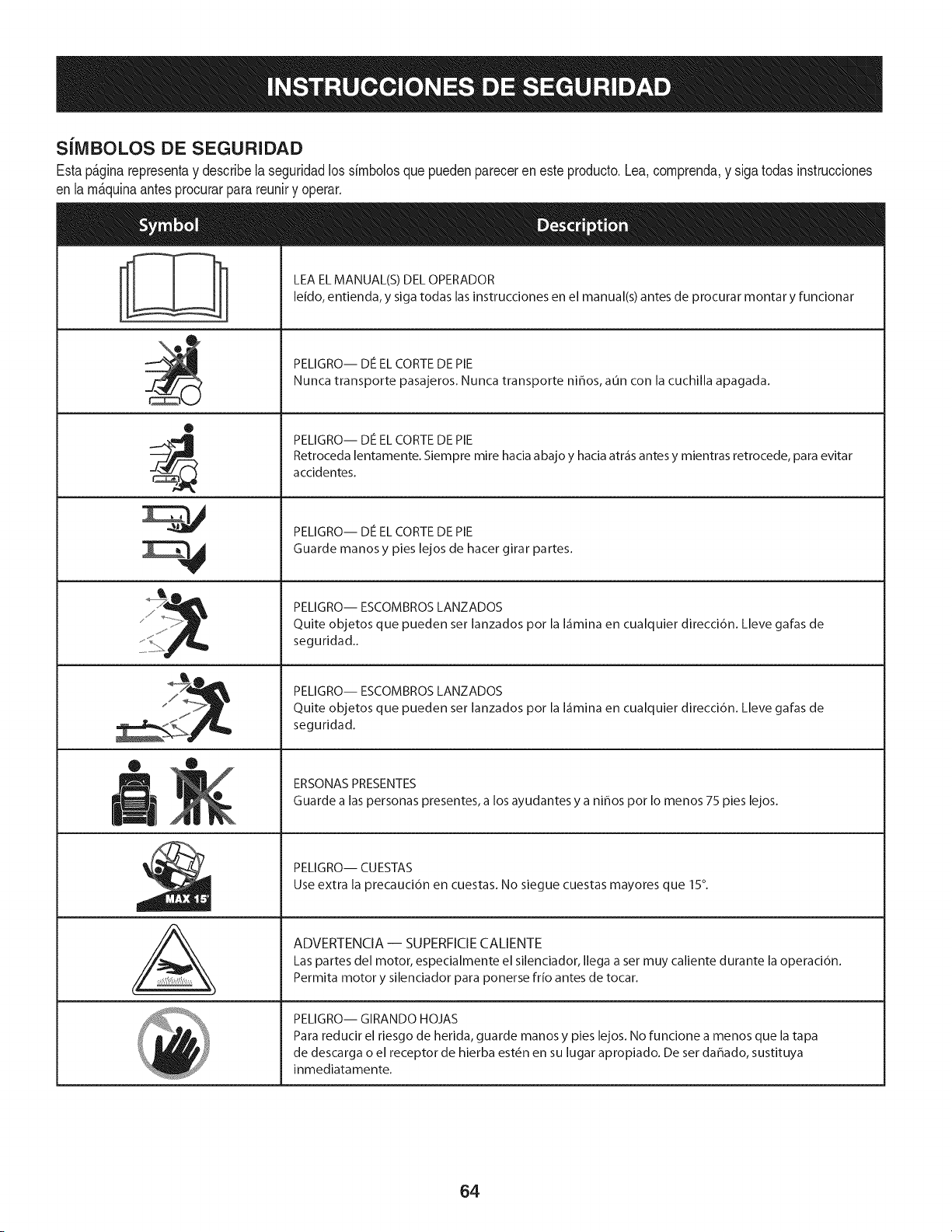
S[IVIBOLOS DE SEGURIDAD
Estap&ginarepresentay describelaseguridadlos simbolosquepuedenpareceren este producto.Lea,comprenda,y sigatodasinstrucciones
en lam_quinaantesprocurarpara reuniry operar.
i
i
®
J
®
,E,
AL
LEA EL MANUAL(S) DEL OPERADOR
leido, entienda, y siga todas las instrucciones en el manual(s) antes de procurar montar y funcionar
PELIGRO-- DE EL CORTE DE PIE
Nunca transporte pasajeros. Nunca transporte nihos, aun con la cuchilla apagada.
PELIGRO-- DE EL CORTE DE PIE
Retroceda lentamente. Siempre mire hacia abajo y hacia atr_is antes y mientras retrocede, para evitar
accidentes.
PELIGRO-- DE EL CORTE DE PIE
Guarde manos y pies lejos de hacer girar partes.
PELIGRO-- ESCOMBROS LANZADOS
Quite objetos que pueden set lanzados pot la I_imina en cualquier direcci6n. Lleve galas de
seguridad..
PELIGRO-- ESCOMBROS LANZADOS
Quite objetos que pueden set lanzados pot la I_imina en cualquier direcci6n. Lleve galas de
seguridad.
ERSONAS PRESENTES
Guarde alas personas presentes, a los ayudantes y a nihos pot Io menos 75 pies lejos.
PELIGRO-- CUESTAS
Use extra la precauci6n en cuestas. No siegue cuestas mayores que 15°.
ADVERTENCIA-- SUPERFICIE CALIENTE
Las partes del motor, especialmente el silenciador, Ilega a set muy caliente durante la operaci6n.
Permita motor y silenciador para ponerse frio antes de tocar.
PELIGRO-- GIRANDO HOJAS
Para reducir el riesgo de herida, guarde manos y pies lejos. No funcione a menos que la tapa
de descarga o el receptor de hierba est6n en su lugar apropiado. De ser dahado, sustituya
inmediatamente.
64
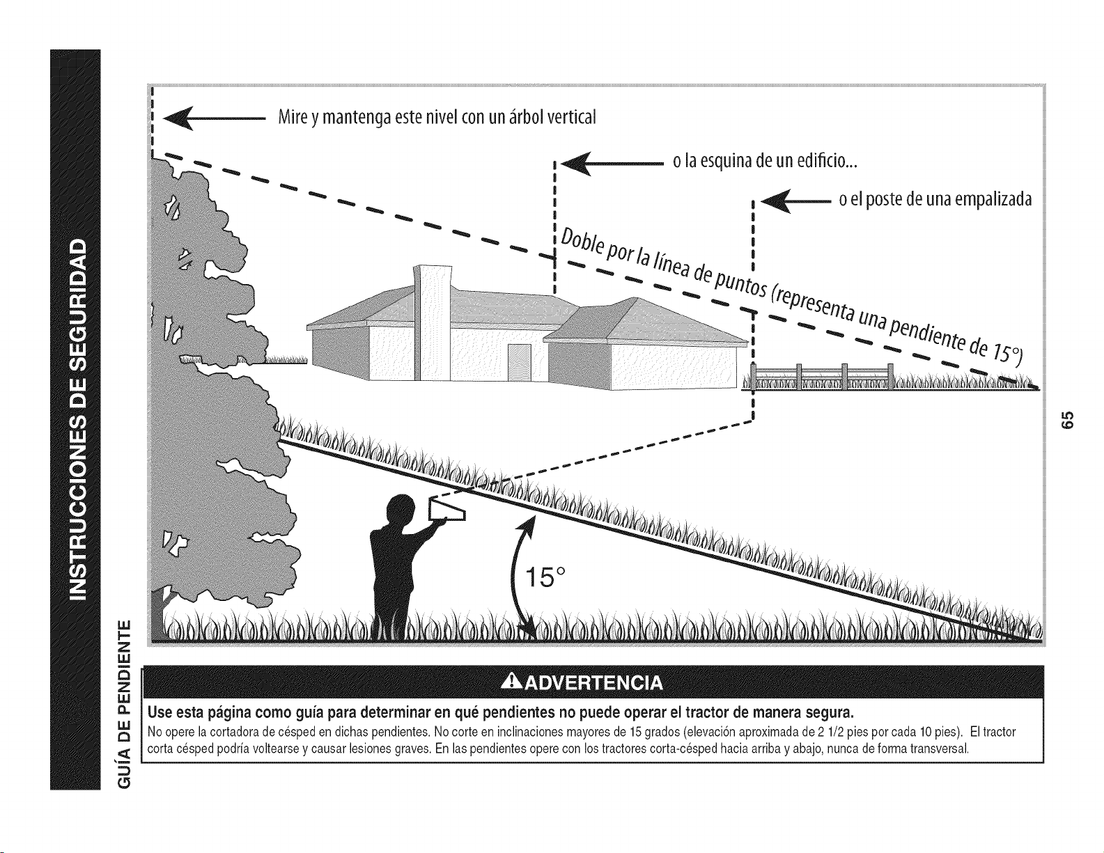
Z
uJ
o [aesqu[nadeunedifido...
15 °
1.0
Use esta pagina como guia para determinar en qu_ pendientes no puede operar el tractor de manera segura.
Nooperelacortadoradecespeden dichaspendientes.Nocorteen inclinacionesmayoresde 15grados(elevaci6naproximadade 2 1/2pies por cada 10 pies). Eltractor
cortacesped podriavoltearsey causarlesionesgraves.Enlas pendientesoperecon los tractorescorta-cespedhaciaarribay abajo,nuncade formatransversal.
(5
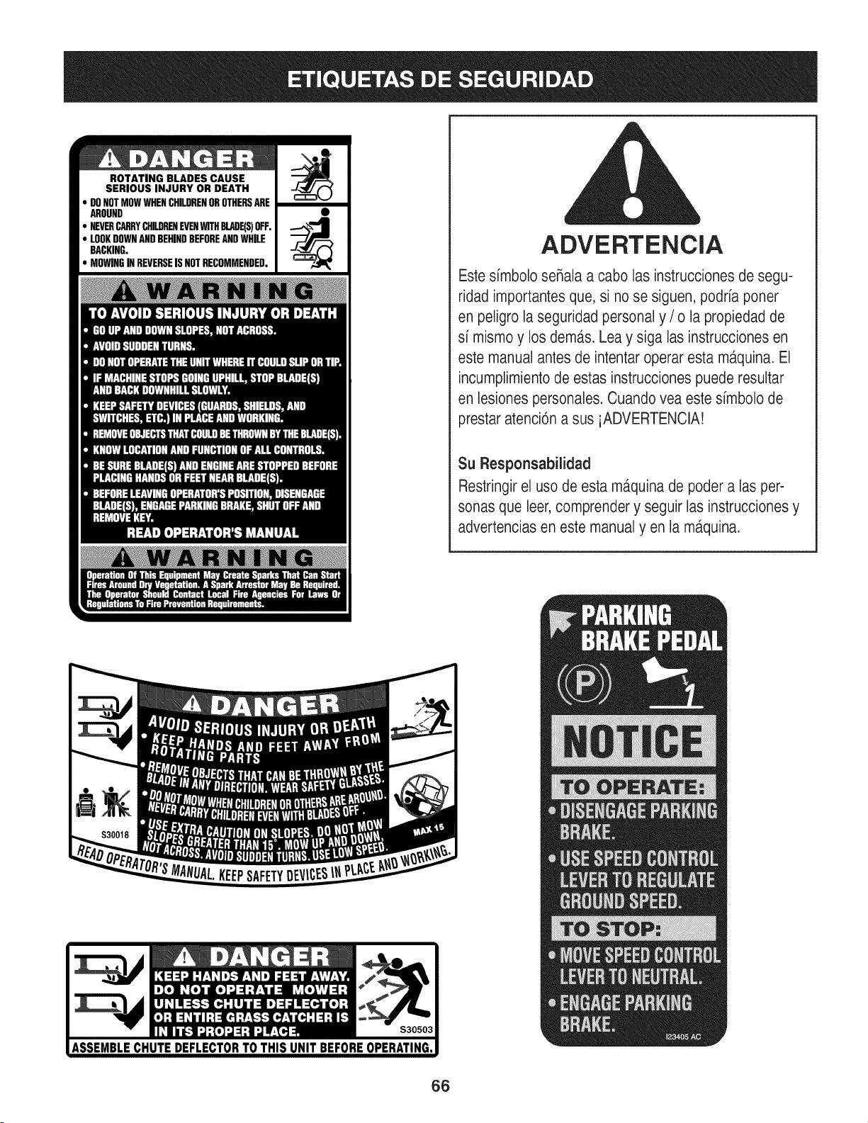
ROTATING BLADES CAUSE
SERIOUS INJURY OR DEATH
DONOTMOWWHENCHILDRENOROTHERSARE
AROUND
NEVERCARRYCHILDRENEVENWITHBLADE(S)OFF.
LOOKDOWNANDBEHINDBEFOREANDWHILE
BACKING.
MOWINGINREVERSEISNOTRECOMMENDED.
ADVERTENCIA
Este simbolo seRalaa cabo las instrucciones de segu-
ridad importantesque, si no se siguen, podria poner
en peligro la seguridad personal y / o la propiedad de
si mismo y los dem,_s.Lea y siga las instrucciones en
este manual antes de intentar operar esta m_tquina.El
incumplimientode estas instruccionespuede resultar
en lesiones personales. Cuando vea este simbolo de
prestar atenci6n a sus iADVERTENCIA!
Su Responsabilidad
Restringirel uso de esta ma.quinade poder alas per-
sonas que leer,comprender y seguir las instruccionesy
advertencias en este manualyen la m,_quina.
66
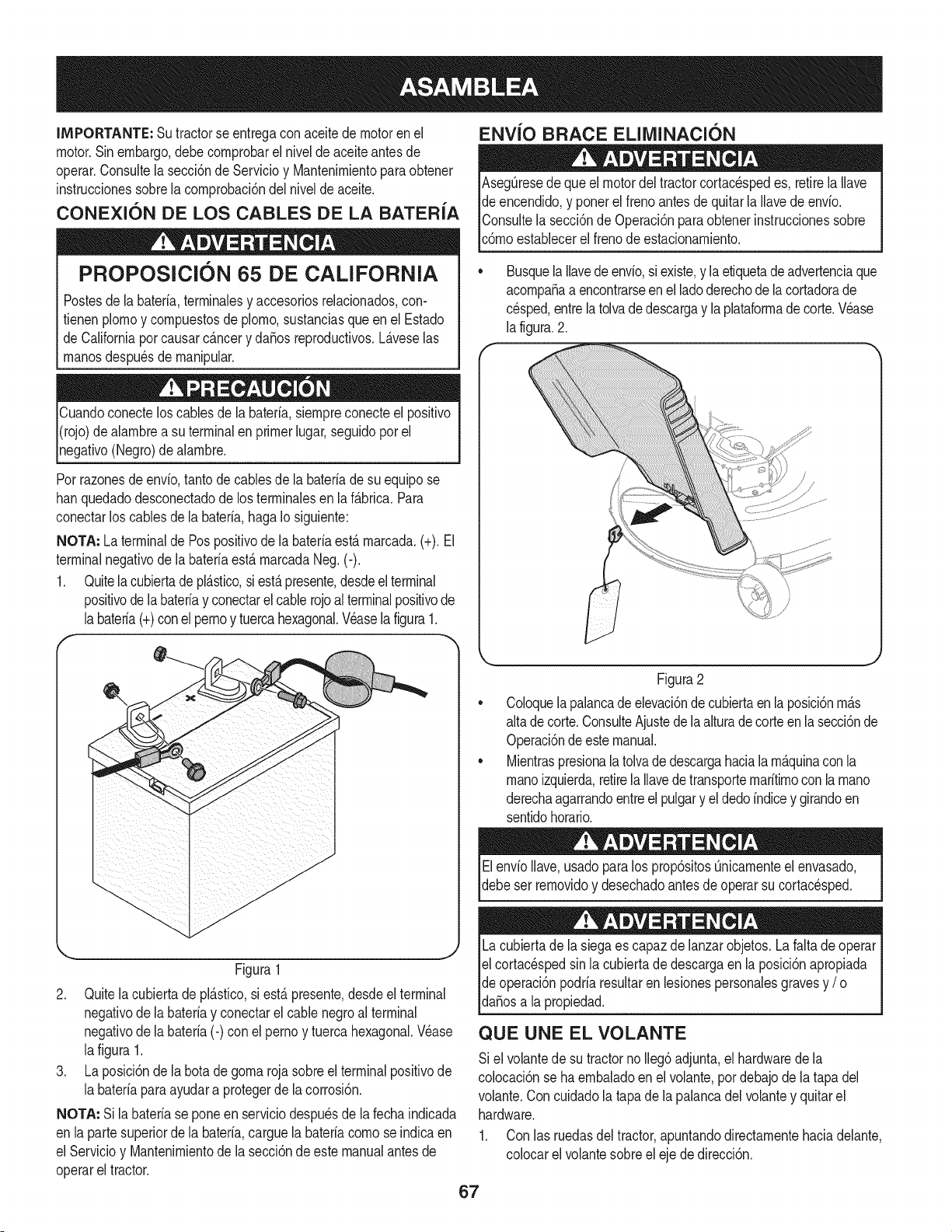
IMPORTANTE: Sutractorse entregaconaceitede motoren el
motor.Sinembargo,debecornprobarel nivelde aceiteantesde
operar.Consultela secci6nde Servicioy Mantenirnientoparaobtener
instrucdonessobrelacornprobad6ndelnivelde aceite.
CONEXION DE LOS CABLES DE LA BATERIA
PROPOSlClON 65 DE CALIFORNIA
Postesdela bateria,terrninalesy accesoriosrelacionados,con-
fienen plornoy cornpuestosde plorno,sustanciasqueen el Estado
de Californiapor causarc_.ncery dafios reproducfivos.L_.veselas
rnanosdespu6sde rnanipular.
Cuandoconecteloscablesde la bateria,siernpreconecteel posifivo
I(rojo)dealarnbrea su terminalenprimerlugar,seguidopor el
pgafivo (Negro)de alarnbre.
Porrazonesde envio,tantode cablesde la bateriade su equipose
hanquedadodesconectadode los terrninalesen la f_.brica.Para
conectarlos cablesde la bateria,hagaIo siguiente:
NOTA: La terminalde Pospositivode la bateriaest,. rnarcada.(+). El
terminalnegativode la bateriaest&rnarcadaNeg.(-).
1. Quitela cubiertadepl&stico,si est&presente,desdeelterminal
positivode labateriay conectarelcablerojoalterminalpositivode
Jabateria(+)conel pernoy tuercahexagonal.Veaselafigura1.
f --,,
ENVlO BRACE ELllVIINACI(SN
AsegQresedeque el motordel tractorcortacespedes, retirelaIlave
de encendido,y ponerel frenoantesde quitarla Ilavedeenvio.
IConsultela secci6nde Operaci6nparaobtenerinstruccionessobre
lc6rnoestablecerel frenode estacionarniento.
Busquela Ilavedeenvio,siexiste,y laetiquetadeadvertenciaque
acornpafiaa encontrarseenel ladoderechode la cortadorade
cesped,entrelatolvadedescargay laplataforrnade corte.Vease
la figura.2.
Figura1
2. Quitelacubiertadepl_.stico,si est,.presente,desdeel terminal
negativode la bateriay conectarel cable negroal terminal
negativode la bateria(-) con elperno y tuerca hexagonal.V6ase
lafigura 1.
3. La posici6nde la botadegornarojasobreel terminalpositivode
la bateriaparaayudara protegerde lacorrosi6n.
NOTA: Si labateriase poneenserviciodespuesde la fechaindicada
en lapartesuperiorde la bateria,carguela bateriacornose indicaen
el Servicioy Mantenirnientode la secci6nde este manualantesde
operarel tractor.
Figura2
Coloquelapalancade elevaci6nde cubiertaen la posici6nrn_.s
altade corte.ConsulteAjustede laalturadecorteenlasecci6nde
Operaci6ndeestemanual.
Mientraspresionalatolvadedescargahaciala rn_.quinacon la
rnanoizquierda,retirela Ilavedetransporternaritirnoconla rnano
derechaagarrandoentreel pulgary el dedoindicey girandoen
sentidohorario.
ElenvioIlave,usadoparalos prop6sitosQnicarnenteel envasado,
debeser rernovidoy desechadoantesde operarsu cortacesped.
Lacubiertade la siegaes capazdelanzarobjetos.La faltade operar
el cortac6spedsin lacubiertade descargaen la posici6napropiada
de operaci6npodriaresultarenlesionespersonalesgravesy / o I
ldafiosa a propedad. j
QUE UNE EL VOLANTE
Si el volantede su tractornoIleg6adjunta,el hardwarede la
colocaci6nse haernbaladoenel volante,por debajode la tapa del
volante.Con cuidadola tapade lapalancadel volantey quitarel
hardware.
1. Con las ruedasdel tractor,apuntandodirectarnentehaciadelante,
colocarel volantesobreeleje de direcci6n.
67
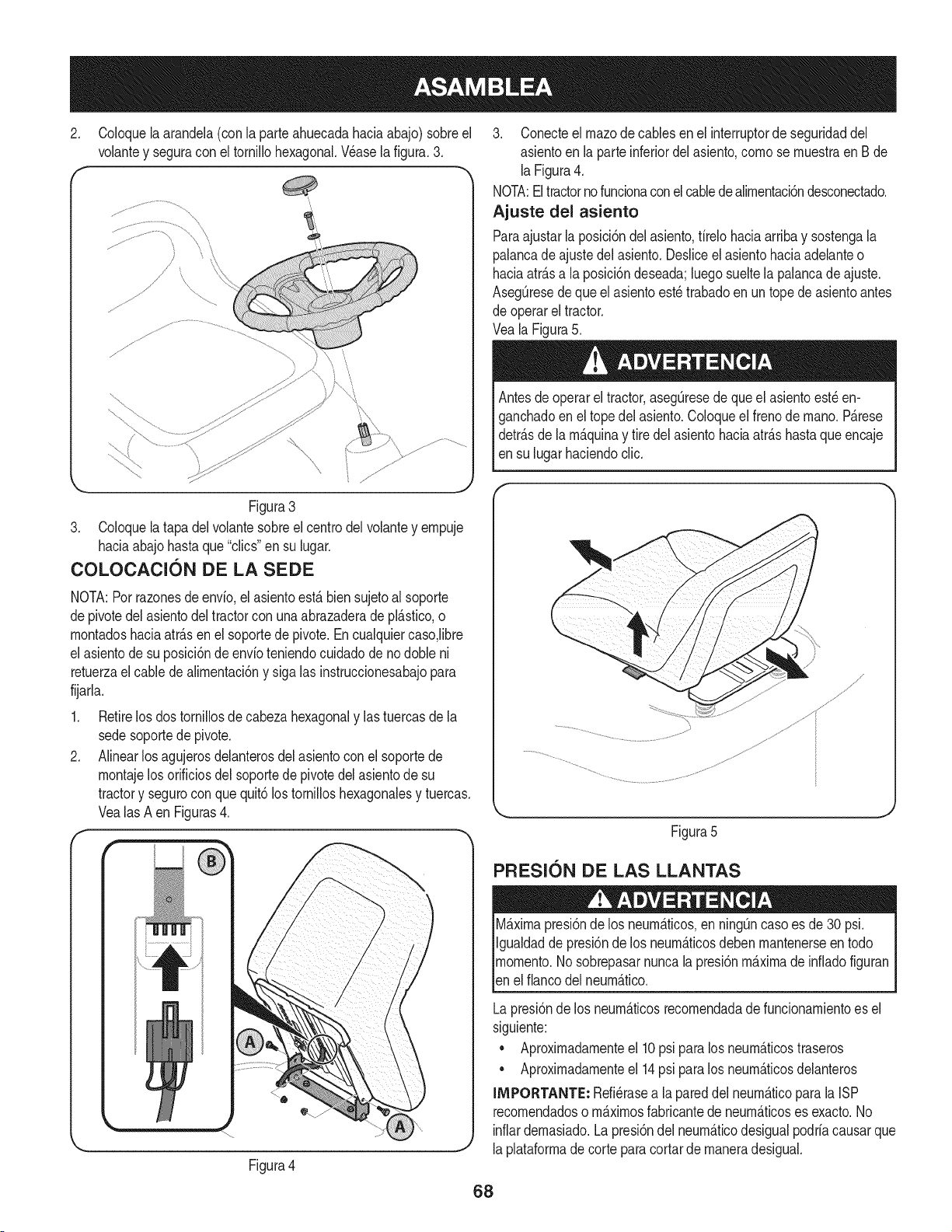
2. Coloquela arandela(con la parteahuecadahaciaabajo)sobreel
volantey seguracon el tornillohexagonal.Wase la figura.3.
f -,
Figura3
3. Coloquela tapadelvolantesobreel centrodel volantey empuje
haciaabajohastaque"clics"en su lugar.
COLOCAClON DE LA SEDE
NOTA:Porrazonesde envfo,el asientoest,. biensujetoal soporte
depivotedel asientodel tractorcon unaabrazaderadepl_.stico,o
montadoshaciaatr_.sen el soportede pivote.Encualquiercaso,libre
el asientode su posici6ndeenvfoteniendocuidadode nodoble ni
retuerzael cablede alimentaci6ny sigalas instruccionesabajopara
fijarla.
1. Retirelos dostornillosde cabezahexagonaly lastuercasdela
sedesoportede pivote.
2. Alinearlosagujerosdelanterosdel asientoconel soportede
montajelosorificiosdelsoportede pivotedelasientode su
tractory segurocon quequit6los tomilloshexagonalesy tuercas.
Vealas A en Figuras4.
f-
Figura4
3. Conecteel rnazode cablesen el interruptorde seguridaddel
asientoen la parteinferiordelasiento,como se muestraen Bde
laFigura4.
NOTA:El tractornofuncionaconel cabledealimentaci6ndesconectado.
Ajuste del asiento
Paraajustarla posici6ndel asiento,firelohaciaarribay sostengala
palancadeajustedel asiento.Desliceel asientohaciaadelanteo
haciaatr_.sa la posici6ndeseada;luegosueltela palancadeajuste.
AsegQresedeque el asientoest_trabadoen un topede asientoantes
de operarel tractor.
Veala Figura5.
Antesde operarel tractor,asegQresede que elasientoest_ en-
ganchadoenel topedel asiento.Coloqueel frenode mano. P_.rese
detr_.sde la m_.quinay tire delasientohaciaatr_.shastaqueencaje
en su lugarhaciendoclic.
Figura5
PFIESl0N DE LAS LLANTAS
M_.ximapresi6nde los neum_.ticos,en ning_ncaso es de 30 psi.
Igualdadde presi6nde los neum_.ticosdebenmantenerseen todo
momento.Nosobrepasarnuncala presi6nm_.ximade infiadofiguran
len e f anco de neum_.tco.
Lapresi6nde los neum_.ticosrecomendadade funcionamientoes el
siguiente:
• Aproximadamenteel 10psi paralos neum_.ticostraseros
• Aproximadamenteel 14psi paralos neum_.ticosdelanteros
IMPORTANTE: Refi_rasea lapareddel neum_.ticopara la ISP
recomendadoso m_.ximosfabricantede neum_.ticoses exacto.No
inflardemasiado.Lapresi6ndel neum_.ticodesigualpodriacausarque
laplataformade corte paracortarde maneradesigual.
68
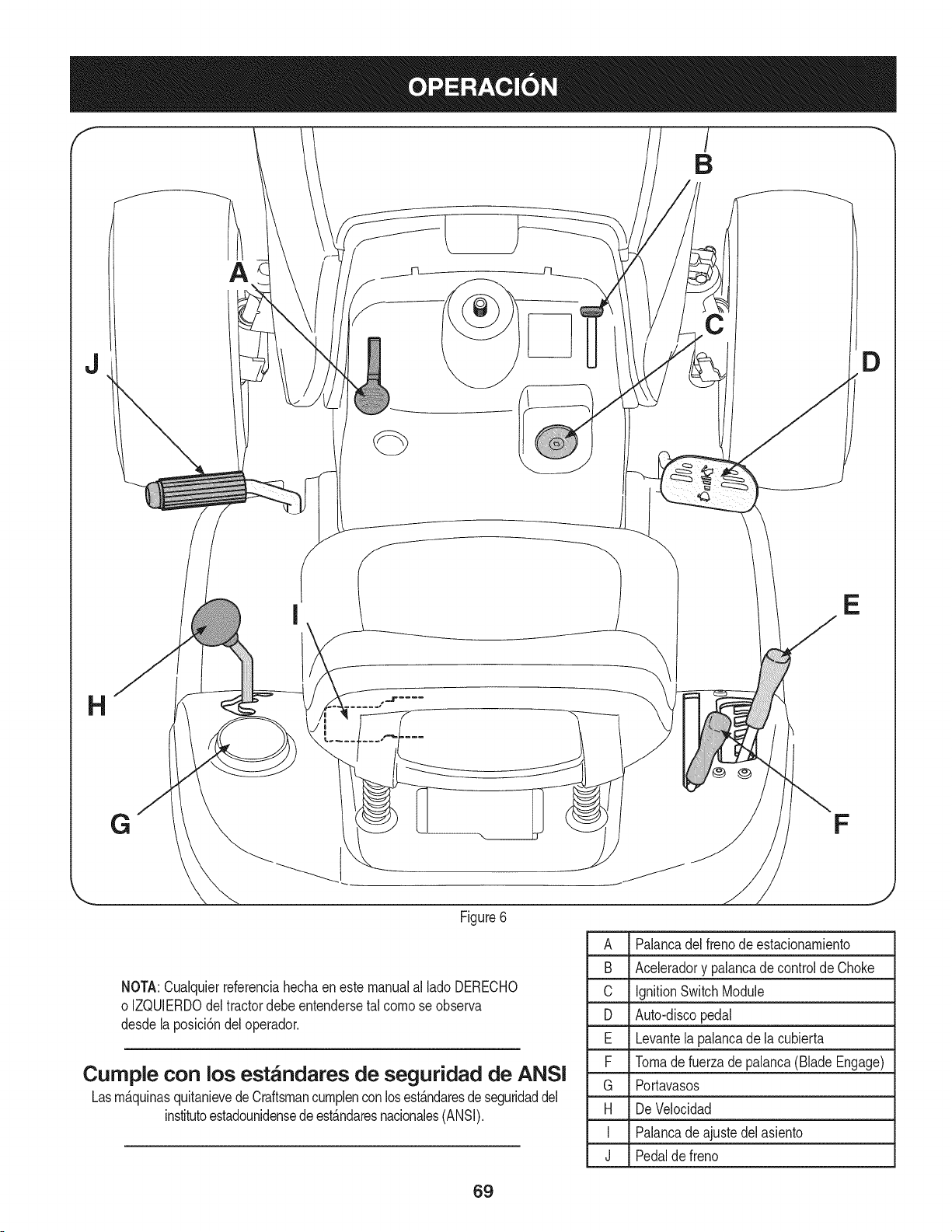
B
A
J D
I
E
Figure6
NOTA:Cualquierreferenciahechaenestemanualal ladoDERECHO
o IZQUlERDOdel tractordebeentendersetal comose observa
desdelaposici6ndeloperador.
Cumple con los est_ndares de seguridad de ANSI
Lasm_.quinasquitanievedeCraftsmancumplenconlosest_.ndaresdeseguridaddel
institutoestadounidensedeest_.ndaresnacionales(ANSI).
A Palancadel frenode estacionamiento
B Aceleradory palancadecontroldeChoke
C IgnitionSwitchModule
D Auto-discopedal
E Levantelapalancade la cubierta
F Tomadefuerzadepalanca(Blade Engage)
G Portavasos
H De Velocidad
I Palancade ajustedelasiento
J Pedalde freno
69
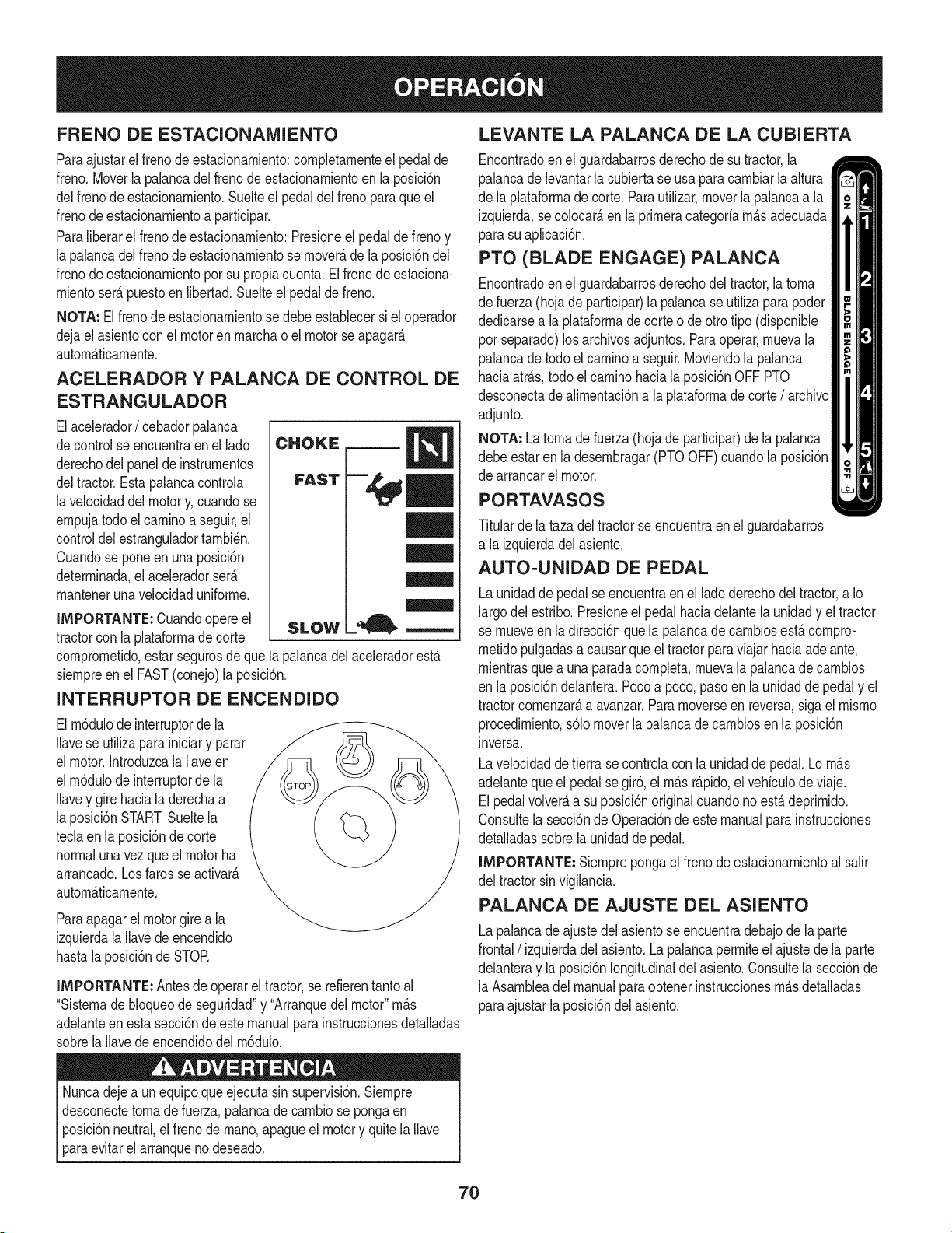
FRENO DE ESTACIONAIVllENTO
Paraajustarel frenode estacionarniento:cornpletarnenteel pedalde
freno.Moverla palancadel frenode estacionarnientoen la posici6n
delfrenode estacionarniento.Suelteel pedaldelfreno paraqueel
frenodeestacionarnientoa participar.
Paraliberarel frenode estacionarniento:Presioneel pedalde frenoy
la palancadelfrenode estacionarnientose rnover_,dela posici6ndel
frenodeestacionarnientoporsu propiacuenta.Elfrenode estaciona-
rnientoser_.puestoen libertad.Suelteel pedalde freno.
NOTA: El frenode estacionarnientosedebeestablecersi el operador
dejael asientocon el motoren rnarchao el motorse apagar_.
autorn_.ticarnente.
ACELERADOR Y PALANCA DE CONTROL DE
ESTRANGULADOR
Elacelerador/ cebadorpalanca
decontrol seencuentraenel lado
derechodel paneldeinstrurnentos
deltractor.Estapalancacontrola
lavelocidaddelmotory,cuandose
ernpujatodo elcarninoa seguir,el
controldelestranguladortarnbi_n.
Cuandose poneen unaposici6n
deterrninada,el aceleradorser_.
rnantenerunavelocidaduniforrne.
IMPORTANTE: Cuandoopereel
tractorcon la plataforrnade corte
SLOW
cornprornetido,estar segurosde que la palancadelaceleradorest,.
siernpreen el FAST(conejo)la posici6n.
INTERRUPTOR DE ENCENDIDO
El rn6dulode interruptorde la
Ilavese utilizapara iniciary parar
el motor.IntroduzcalaIlaveen
el rn6dulode interruptorde la
Ilavey girehaciala derechaa
la posici6nSTART.Sueltela
teclaen la posici6nde corte
normalunavezqueel motorha
arrancado.Losfaros se activar_.
autorn_.ticarnente.
Paraapagarel motorgirea la
izquierdalaIlavede encendido
hastala posici6nde STOR
IMPORTANTE: Antesde operarel tractor,se refierentantoal
"Sisternade bloqueode seguridad"y "Arranquedel motor"rn_.s
adelanteenestasecci6nde este manualparainstruccionesdetalladas
sobrela Ilavede encendidodel rn6dulo.
Nuncadejea un equipoqueejecutasin supervisi6n.Siernpre
desconectetornadefuerza,palancade carnbiose pongaen
posici6nneutral,el frenode rnano,apagueel motory quitela Ilave
paraevitarel arranquenodeseado.
LEVANTE LA PALANCA DE LA CUBIERTA
Encontradoenel guardabarrosderechodesu tractor,la
palancadelevantarla cubiertase usa paracarnbiarla altura
de la plataforrnadecorte. Parautilizar,moverla palancaa la
izquierda,secolocar_,en la prirneracategoriarn_.sadecuada
parasu aplicaci6n.
PTO (BLADE ENGAGE) PALANCA
Encontradoenel guardabarrosderechodeltractor,latorna
de fuerza(hojade participar)la palancase utilizaparapoder
dedicarsea laplataforrnade corte o deotrotipo (disponible
por separado)los archivosadjuntos.Paraoperar,rnuevala
palancadetodoel carninoa seguir.Moviendola palanca
haciaatr_.s,todo el carninohacia laposici6nOFF PTO
desconectade alirnentaci6na la plataforrnade corte/ archivo
adjunto.
NOTA: Latornade fuerza(hojade participar)de lapalanca
debeestar enla desernbragar(PTOOFF)cuandola posici6n
de arrancarel motor.
PORTAVASOS
Titularde la tazadel tractorse encuentraenel guardabarros
a la izquierdadelasiento.
AUTO-UNIDAD DE PEDAL
Launidadde pedalse encuentraenel lado derechodel tractor,a Io
largodel estribo.Presioneel pedalhaciadelantela unidady el tractor
se rnueveen la direcci6nquela palancadecarnbiosest,.cornpro-
rnetidopulgadasa causarqueel tractorparaviajar haciaadelante,
rnientrasque a unaparadacornpleta,rnuevala palancade carnbios
en la posici6ndelantera.Pocoa poco,pasoenla unidadde pedaly el
tractorcornenzar_,a avanzar.Pararnoverseen reversa,sigael rnisrno
procedirniento,s61omoverla palancadecarnbiosenla posici6n
inversa.
Lavelocidaddetierra se controlaconla unidadde pedal.Lorn_.s
adelantequeel pedal segir6, el rn_.sr_.pido,el vehiculode viaje.
Elpedalvolver_,a su posici6noriginalcuandono est,.deprirnido.
Consultela secci6nde Operaci6nde este manualparainstrucciones
detalladassobrelaunidadde pedal.
IMPORTANTE: Siernprepongael frenodeestacionarnientoal salir
del tractorsinvigilancia.
PALANCA DE AJUSTE DEL ASIENTO
Lapalancade ajustedelasientose encuentradebajode la parte
frontal/izquierda delasiento.La palancaperrniteel ajustede la parte
delanteray laposici6nlongitudinaldel asiento.Consultelasecci6nde
la Asarnbleadel manualparaobtenerinstruccionesrn_.sdetalladas
paraajustarla posici6ndel asiento.
70
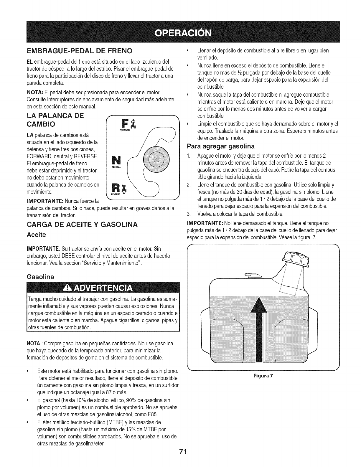
EMBRAGUE-PEDAL DE FRENO
ELernbrague-pedaldel freno est,. situadoen el lado izquierdodel
tractorde c_sped,a Io largodel estribo.Pisarel ernbrague-pedalde
frenoparala participaci6ndel discode frenoy Ilevarel tractora una
paradacornpleta.
NOTA: El pedaldebeser presionadaparaencenderel motor.
ConsulteInterruptoresde enclavarnientode seguridadrn_.sadelante
enesta secci6ndeestemanual.
LA PALANCA DE f
cAMBIo F ;i;
LA palancade carnbiosest,.
situadaenel lado izquierdode la
defensay tienetres posiciones,
FORWARD,neutraly REVERSE.
Elernbrague-pedalde freno
debeestardeprirnidoy el tractor
nodebe estaren rnovirniento
cuandola palancade carnbiosen
rnovirniento.
IMPORTANTE: Nuncafuercela
palancade carnbios.Si Io hace,puederesultarengravesdaSosa la
transrnisi6ndel tractor.
CARGA DE ACEITE Y GASOLINA
Aceite
• Llenarel dep6sitodecombustiblealaire libreo en lugar bien
ventilado.
• NuncaIleneen excesoel dep6sitode combustible.Lleneel
tanquenorn_.sde 1/2pulgadapordebajode la basedel cuello
del tap6ndecarga, paradejarespaciopara laexpansi6ndel
combustible.
• Nuncasaquela tapadel combustibleniagreguecombustible
rnientrasel motorest,.calienteo en rnarcha.Dejequeel motor
seenfrie porIornenosdos rninutosantesde volvera cargar
combustible.
• Lirnpieel combustiblequese hayaderrarnadosobreel motory el
equipo.Trasladela rn_.quinaa otrazona. Espere5 rninutosantes
de encenderelmotor.
Para agregar gasolina
1. Apagueel motory dejequeelmotorseenfrieporIornenos2
rninutosantesde removerla tapadelcombustible.El tanquede
gasolinaseencuentradebajodelcap6.Retirelatapadelcombus-
tiblegirandohacialaizquierda.
2. Lleneel tanquede combustiblecongasolina.Utilices61olirnpiay
fresca(norn_.sde30diasde edad),lagasolinasinplorno.Llene
el tanquenopulgadarn_.sde 1/ 2 debajode la basedelcuellode
Ilenadoparadejarespacioparalaexpansi6ndelcombustible.
3. Vuelvaacolocarlatapadelcombustible.
IMPORTANTE: Nollenedernasiadoel tanque.Lleneel tanqueno
pulgadarn_.sde 1/ 2 debajodela basedel cuellode Ilenadoparadejar
espacioparalaexpansi6ndel combustible.Wase la figura.7.
IMPORTANTE:Su tractorse enviacon aceiteen el motor.Sin
embargo,usted DEBEcontrolarel nivelde aceiteantesde hacerlo
funcionar.Vealasecci6n"Servicioy Mantenirniento".
Gasolina
Tengarnuchocuidadoal trabajarcon gasolina.Lagasolinaes surna-
rnenteinfiarnabley susvaporespuedencausarexplosiones.Nunca
carguecombustibleenla rn_.quinaenun espaciocerradoo cuandoel
motorest,.calienteo en rnarcha.Apaguecigarrillos,cigarros,pipasy
otrasfuentesde cornbusti6n.
NOTA: Cornpregasolinaen pequeSascantidades.No usegasolina
quehayaquedadode la ternporadaanterior,pararninirnizarla
forrnaci6nde dep6sitosdegornaen el sisternadecombustible.
• Estemotorest,.habilitadoparafuncionarcongasolinasin plorno.
Paraobtenerelrnejorresultado,Ileneel dep6sitode combustible
Onicarnentecongasolinasin plornolirnpiay fresca,enun surtidor
queindiqueun octanajeiguala 87 o rn_.s.
• Elgasohol(hasta10%dealcoholefilico,90%de gasolinasin
plornoporvolurnen)es un combustibleaprobado.No seaprueba
el usode otrasrnezclasdegasolina/alcohol,cornoE85.
• El_ter rnefilicoterciario-bufilico(MTBE)y las rnezclasde
gasolinasin plorno(hastaun rn_.xirnode 15%de MTBEpor
volurnen)son combustiblesaprobados.Nose apruebael uso de
otrasrnezclasdegasolina/eter.
71
Figura 7
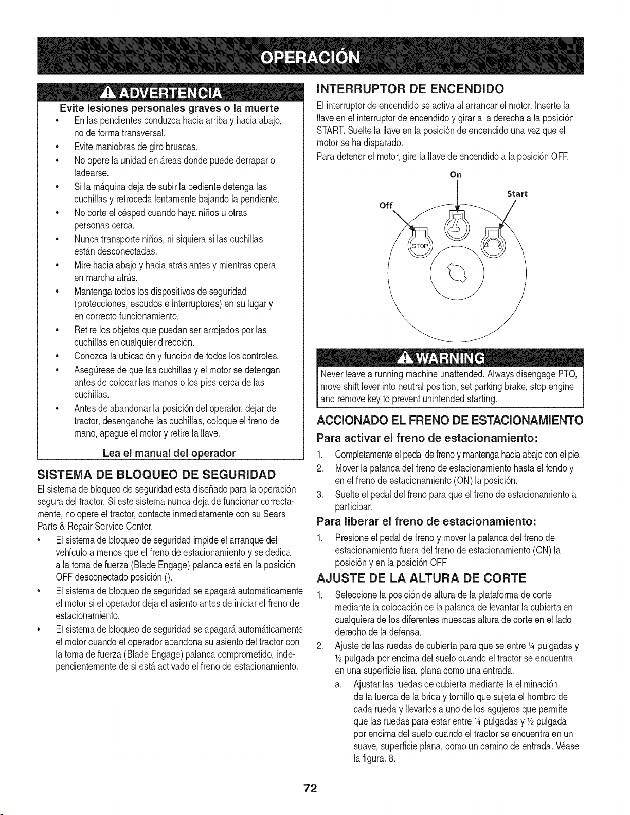
Evite lesiones personales graves o la muerte
• Enlas pendientesconduzcahaciaarribay haciaabajo,
node forrnatransversal.
• Eviternaniobrasde girobruscas.
• No operela unidaden _.reasdondepuedederraparo
ladearse.
• Si larn_.quinadejade subirla pedientedetengalas
cuchillasy retrocedalentarnentebajandola pendiente.
• No corteel c_spedcuandohayani_osu otras
personascerca.
• Nuncatransporteni_os,ni siquierasi las cuchillas
est_.ndesconectadas.
• Mirehaciaabajoy haciaatr_.santesy rnientrasopera
en rnarchaatr_.s.
• Mantengatodoslos dispositivosde seguridad
(protecciones,escudose interruptores)ensu lugary
encorrectofuncionarniento.
• Retirelos objetosquepuedanserarrojadospor las
cuchillasencualquierdirecci6n.
• Conozcala ubicaci6ny funci6nde todoslos controles.
• AsegQresedequelas cuchillasy el motorsedetengan
antesde colocarlas rnanoso los piescercade las
cuchillas.
• Antesde abandonarlaposici6ndel operafor,dejar de
tractor,desenganchelascuchillas,coloqueel frenode
rnano,apagueel motory retirela Ilave.
Lea el manual del o erador
SISTENIA DE BLOQUEO DE SEGURIDAD
El sisternade bloqueode seguridadest&dise_adoparala operaci6n
seguradel tractor.Si estesisternanuncadeja defuncionarcorrecta-
rnente,no opereel tractor,contacteinrnediatarnentecon su Sears
Parts& RepairServiceCenter.
• El sisternade bloqueode seguridadirnpideel arranquedel
vehiculoa rnenosque elfrenode estacionarnientoy se dedica
a latornade fuerza(Blade Engage)palancaest,.en la posici6n
OFFdesconectadoposici6nO.
• El sisternade bloqueode seguridadseapagar_,autorn_.ticarnente
el motorsi el operadordejael asientoantesde iniciarel frenode
estacionarniento.
• El sisternade bloqueode seguridadseapagar_,autorn_.ticarnente
el motorcuandoel operadorabandonasuasientodel tractorcon
latornade fuerza(Blade Engage)palancacornprornetido,inde-
pendienternentede si est,.activadoel frenode estacionarniento.
INTERRUPTOR DE ENCENDIDO
Elinterruptorde encendidose activaalarrancarel motor.Insertela
Ilaveen el interruptorde encendidoy girara la derechaa la posici6n
START.Sueltela Ilaveen la posici6ndeencendidounavezqueel
motorse hadisparado.
Paradetenerel motor,gire la Ilavede encendidoa la posici6nOFE
On
Start
off
Neverleavea runningmachineunattended.AlwaysdisengagePTO,
moveshiftleverinto neutralposition,set parkingbrake,stopengine
and removekey to preventunintendedstarting.
ACCIONADO EL FRENO DE ESTACIONAlVUENTO
Para activar el freno de estacionamiento:
1. Completarnenteelpedaldefrenoy rnantengahaciaabajoconel pie.
2. Moverla palancadel frenode estacionarnientohastael rondoy
en elfrenode estacionarniento(ON)la posici6n.
3. Suelteel pedaldel frenoparaqueel frenode estacionarnientoa
participar.
Para liberar el freno de estacionamiento:
1. Presioneel pedalde frenoy moverla palancadel frenode
estacionarnientofueradelfrenode estacionarniento(ON) la
posici6nyen la posici6nOFE
AJUSTE DE LA ALTURA DE CORTE
.
Seleccionela posici6nde alturade la plataforrnadecorte
rnediantelacolocaci6nde la palancade levantarla cubiertaen
cualquierade losdiferentesrnuescasalturade corteen el lado
derechodela defensa.
Ajustede las ruedasde cubiertaparaquese entre1Apulgadasy
1/2pulgadapot encirnadel suelocuandoel tractorse encuentra
en unasuperficielisa,planacornounaentrada.
a. Ajustarlasruedasde cubiertarnediantelaelirninaci6n
de latuerca de labrida y tornilloquesujetael hornbrode
cada rueday Ilevarlosa unode los agujerosqueperrnite
que las ruedasparaestarentre 1Apulgadasy 1/2pulgada
por encirnadel suelocuandoel tractorse encuentraen un
suave,superficieplana,cornoun carninode entrada.Wase
la figura.8.
72
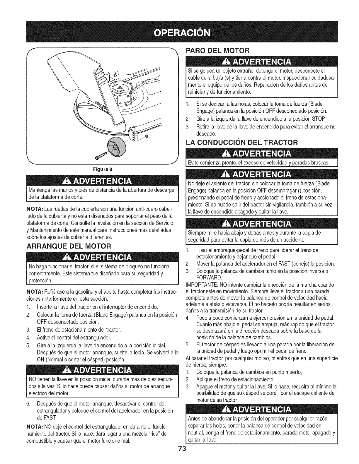
PARO DEL MOTOR
Si se golpeaunobjetoextra,o, detengael motor,desconecteel
cablede la bujfa(s) y tierracontrael motor.Inspeccionarcuidadosa-
rnenteel equipode losda_os.Reparaci6nde los da_osantesde
reiniciary defuncionarniento.
1. Si se dedicanalas hojas,colocar latornade fuerza(Blade
Engage)palancaen la posici6nOFFdesconectadoposici6n.
2. Girea la izquierdala Ilavede encendidoa la posici6nSTOR
3. RetirelaIlavede la Ilavede encendidoparaevitarelarranqueno
deseado.
LA CONDUCCION DEL TRACTOR
Figura 8
Mantengalas rnanosy piesde distanciade la aberturade descarga
de la plataforrnadecorte.
NOTA: Lasruedasde lacubiertasonunafunci6nanti-cuerocabel-
ludode la cubiertay noest_.ndise_adosparasoportarel pesode la
plataforrnadecorte. Consultela nivelaci6nen la secci6ndeServicio
y Mantenirnientode estemanualpara instruccionesrn_.sdetalladas
sobrelos ajustesde cubiertadiferentes.
ARRANQUE DEL MOTOR
No hagafuncionareltractor,si el sisternade bloqueonofunciona
correctarnente.Estesisternarue dise_adoparasu seguridady
protecci6n.
NOTA: Refi_rasea lagasolinay elaceitehastacornpletarlas instruc-
cionesanteriorrnenteen esta secci6n.
1. InsertelaIlavedel tractorenel interruptorde encendido.
2. Colocarla tornadefuerza(BladeEngage)palancaen laposici6n
OFFdesconectadoposici6n.
3. El frenode estacionarnientodel tractor.
4. Activeel controldel estrangulador.
5. Gire a laizquierdala Ilavede encendidoa la posici6ninicial.
Despu_sdequeel motorarranque,sueltela tecla.Se volver_,a la
ON (Normalo cortarel c_sped)posici6n.
NOtienenla llaveenla posici6ninicialdurantern_.sde diezsegun-
dosa la vez.Si Iohace puedecausardaSosal motorde arranque
el_ctricodel motor.
6. Despu_sdequeel motorarranque,desactivarelcontroldel
estranguladory coloqueel controldel aceleradoren laposici6n
de FAST.
NOTA: NOdejeelcontroldelestranguladorenduranteel funcio-
narnientodeltractor.Si Iohace,dar_.lugar a unarnezcla"rica" de
combustibley causarqueel motorfuncionernal.
Evitecornienzapronto,el excesodevelocidady paradasbruscas.
Nodejeel asientodel tractor,sincolocarla tornadefuerza (Blade
Engage)palancaen laposici6nOFFdesernbragar0 posici6n,
presionandoel pedalde frenoy accionadoel frenode estaciona-
rniento.Si no puedesalirdel tractorsin vigilancia,tarnbi_na suvez
la Ilavedeencendidoapagadoy quitarla Ilave.
73
Siernpremirehaciaabajoy detr_.santesy durantela copiade
seguridadparaevitarla copiade rn_.sde unaccidente.
1. Pisarel ernbrague-pedaldefreno paraliberarel frenode
estacionarnientoy dejar queel pedal.
2. Moverlapalancadel aceleradorenel FAST(conejo)la posici6n.
3. Coloquelapalancade carnbiostanto enla posici6ninversao
FORWARD.
IMPORTANTE:NOintentecarnbiarladirecci6nde la rnarchacuando
el tractorest_en rnovirniento.Siernprelleveel tractora unaparada
cornpletaantes demoverla palancadecontroldevelocidadhacia
adelantea atr_.so viceversa.El no hacerlopodriaresultarenserios
da_osa la transrnisi6nde su tractor.
4. Pocoa poco cornienzana ejercerpresi6nen la unidadde pedal.
Cuantorn_.sabajoel pedal seernpuja,rn_.sr_.pidoque eltractor
sedesplazar_,en la direcci6ndeseadasobrela basedela
posici6nde la palancadecarnbios.
5. Eltractorde cespedes Ilevadoa unaparadapor la liberaci6nde
launidadde pedaly luegooprirnirel pedaldefreno.
AI pararel tractor,por cualquierrnotivo,rnientrasqueen unasuperficie
de hierba,siernpre:
1. Coloquelapalancadecarnbiosen puntornuerto,
2. Apliqueel frenode estacionarniento,
3. Apagueel motory quitarla Ilave.Si Io hace,reducir_,al rninirnola
posibilidaddequesu c_spedsedore'"'porel escapecalientedel
motordesu tractor.
Antesde abandonarla posici6ndel operadorporcualquierraz6n,
separarlashojas,ponerla palancade controlde velocidaden
neutral,pongael frenodeestacionarniento,paradamotorapagadoy
quitarla Ilave.
CONDUCCI6N EN LAS LADERAS
INVOLUCRAR A LOS BLADES
Refierenal anchodela pendienteenla seguridadde las pr_.cticasde
operaci6nirnportantesecci6ndelmanualparaayudara deterrninar
zonasde laderadondepuedeoperarel tractorcon total seguridad.
No corteel cespeden pendientescon unainclinaci6nde rn_.sde 15
grados(un aurnentodeaproxirnadarnente2-1/2pies cada 10pies).
Eltractorpuedevolcary causarlesionesgraves.
• Corteel cespedy las pendientes,nuncatransversal.
• Tengaextrernaprecauci6nalcarnbiarde direcci6nen las
pendientes.
• Watchpara los agujeros,grietas,baches,piedrasu otrosobjetos
ocultos.Terrenoirregularpuederevertirla rn_.quina.Elc_sped
alto puedeocultarobst_.culos.
• Evitegirarcuandosecirculaporunapendiente.Siuna vez,debe
hacerse,a suvezpor la pendiente.Elregresode una pendiente
aurnentala posibilidadde un rollover.
• Evitedetenersecuandose conducepot unapendiente.Si es
necesariodetenerrnientrasse conducepot unapendiente,
puestaen rnarchasin problernasy con cuidadoparareducirla
posibilidadde volteareltractorhaciaatr_.s.
Participaci6nde latornade fuerza(BladeEngage)lastransferenciasde
energfaa la plataforrnadecorteo de otrotipo(disponiblepot separado)
los archivosadjuntos.Paraparticiparde las hojas,hagaIosiguiente:
1. Moverla palancade controldelaceleradora la r_.pida(conejo)la
posici6n.
2. Sujetela tornade fuerza(BladeEngage)y girarla palancade
todo el carninoa seguira los novios(ON)la posici6n.
3. Mantengala palancadel aceleradorenel FAST(conejo)la
posici6nparael uso rn_.seficientede la plataforrnade corteo de
otto tipo (disponibleporseparado)los archivosadjuntos.
NOTA: Elmotor seapagar_,autorn_.ticarnentesi latornadefuerza
est,.comprornetidocon la palancadecarnbiosen la posici6nde
rnarchaatr_.scon laNavede encendidoen la posici6nON.
USO DE LA CUBIERTA DE LEVANTE LA
PALANCA DE
Paraelevarlaplataforrnade corte,moverla palancade elevaci6nde
cubiertaa la izquierda,luego secolocaen la ranurarn_.sadecuada
parasu aplicaci6n.ConsulteAjuste laalturade corte anteriorrnenteen
estasecci6n.
74
CORTAR
ParaayudaraevJtarelcontactocon lacuchJllao una lesJ6nen
elobjetolanzado,Mantengaa losespectadores,losayudantes,
los niSosy las mascotaspor Io menos75piesde distanciade la
m_.quinamientrasest,.en funcionamiento.Paradade la m_.quina,si
alguienentraenel _.rea.
La sJguJenteinformacJ6nser_.Qtilcuandose utilizalaplataformade
cortecon sutractor:
Plande su patr6nde corteparaevitarla descargade materiales
hacialas carreteras,aceras,transeQntes,etc.Adem_.s,evitematerial
quese descargacontrauna paredo unaobstrucci6nquepuede
causaraltamateriala rebotarhaciael operador.
FAROS
• LasI_.mparasest_.nONcuandoel motordeltractorse est,.
ejecutando.
• Lasluces se apagacuandola Ilavedecontactose muevea la
posici6nSTOE
• No corteel c6speda la velocidaddeterrenoelevado,especial-
mentesi se ha instaladoun kitde mantilloo colectorde cesped.
• Paraobtenerlos mejoresresultadosse recomiendaque las
dos primerasvueltassecortar&con laaprobad6nde la gesti6n
arrojadohaciael centro.Traslasdos primerasvueltas, invertirel
sentidodelanzarla descargahaciael exteriorde labalanzade
corte.Estoledar&unamejoraparienciaal c6sped.
• No corteel cespeddemasiadocorto.Pastocortoinvita crec-
imientodemalas hierbasy los amarilloscon rapidezen el tiempo
seco.
Cortarel c6spedsiemprese debe hacercon el motora todogas.
• Bajolascondicionesm_.spesadas,puedesernecesariovolversobre
lazonadelcorteporsegundavezparaobteneruncortelimpio.
NOintentecortarespesamalezay malashJerbasyel pastomuyalto.
Sutractorest&diseSadoparacortarelc6sped,uncepillonoest&claro.
Mantengalascuchillasafiladasy sustituirlascuchillasencaso
dedesgaste.ConsulteHojasdecorteenel servicioy la secci6n
Mantenimientode estemanualdeinstruccionesde afilarla hoja
adecuada.
75
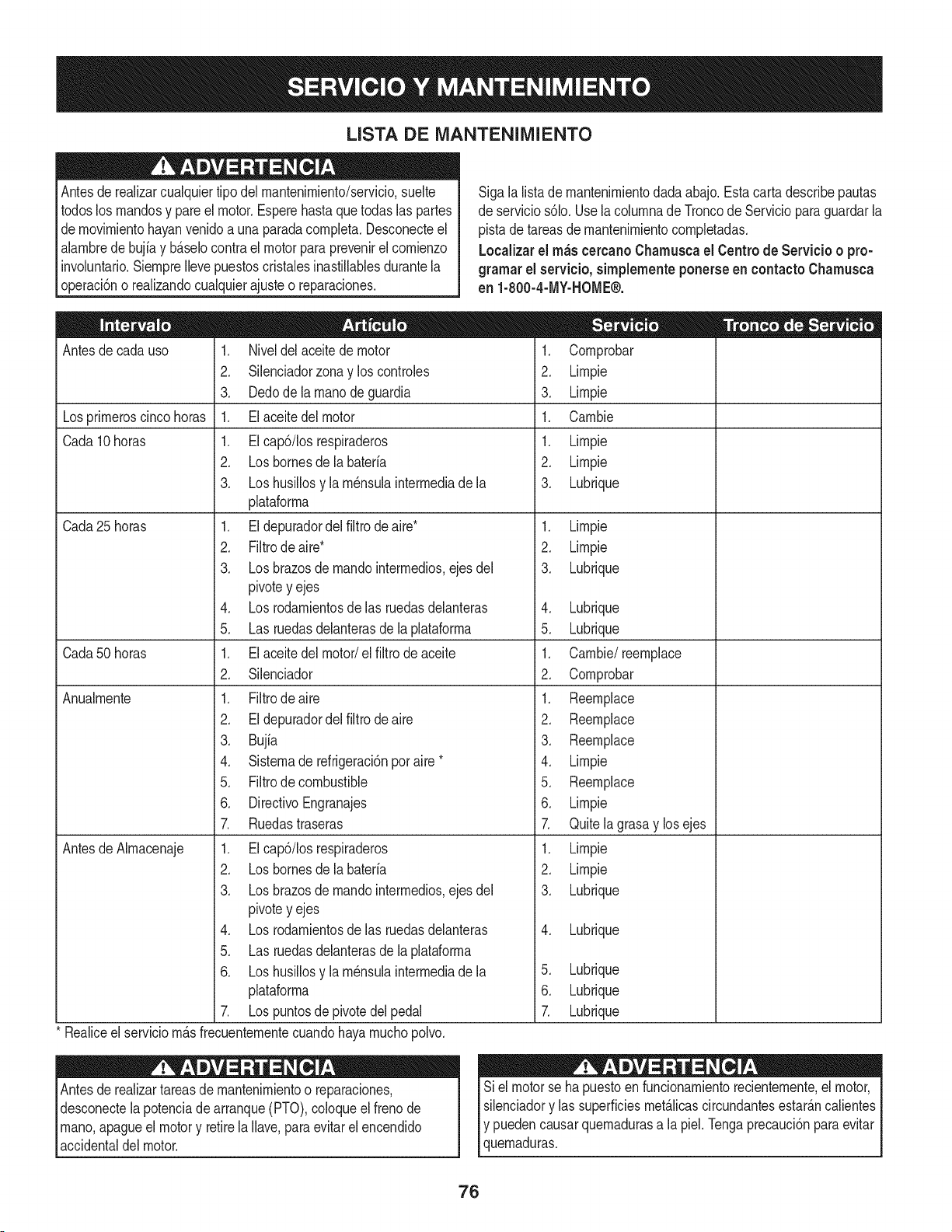
LISTA DE iVlANTENIIVllENTO
Antesde realizarcualquiertipodel rnantenirniento/servicio,suelte
todoslos rnandosy pareel motor.Esperehasta quetodaslas partes
dernovirnientohayanvenidoa unaparadacornpleta.Desconecteel
alarnbrede bujiay b_.selocontra elmotor paraprevenirel cornienzo
involuntario.SiernpreIlevepuestoscristalesinastillablesdurantela
operaci6no realizandocualquierajusteo reparaciones.
Sigala lista de rnantenirnientodadaabajo.Estacarta describepautas
de servicios61o.Usela colurnnade Troncode Servicioparaguardarla
pistade tareasde rnantenirnientocornpletadas.
Localizarel rn_scereanoCharnuscael Centrode Servicio o pro-
grarnar el servicio,sirnplementeponerseen eontactoChamusca
en 1-800-4-MY-HOME®.
Antesde cadauso
Losprirneroscincohoras
Cada10horas
Cada 25 horas
Cada50horas
Anualrnente
Antesde Alrnacenaje
1. Niveldelaceitedemotor
2. Silenciadorzonay los controles
3. Dedode la rnanodeguardia
1. Elaceitedel motor
1. EIcap6/Ios respiraderos
2. Losbornesdela bateria
3. Loshusillosy la rn_nsulainterrnediade la
plataforrna
1. El depuradordelfiltrode aire*
2. Filtrode aire*
3. Losbrazosde rnandointerrnedios,ejes del
pivotey ejes
4. Losrodarnientosde las ruedasdelanteras
5. Las ruedasdelanterasdela plataforrna
1. El aceitedel motor/el filtro deaceite
2. Silenciador
1. Filtrodeaire
2. Eldepuradordelfiltro de aire
3. Bujia
4. Sisternade refrigeraci6nporaire *
5. Filtrode combustible
6. DirectivoEngranajes
7. Ruedastraseras
1. EIcap6/Iosrespiraderos
2. Losbornesdela bateria
3. Losbrazosde rnandointerrnedios,ejes del
pivotey ejes
4. Losrodarnientosde las ruedasdelanteras
5. Las ruedasdelanterasdela plataforrna
6. Loshusillosy la rn_nsulainterrnediade la
plataforrna
7. Lospuntosde pivotedelpedal
* Realiceel serviciorn_.sfrecuenternentecuandohayarnuchopolvo.
Antesde realizartareasde rnantenirnientoo reparaciones,
desconectelapotenciade arranque(PTO),coloqueel frenode
rnano,apagueel motory retirela Ilave,paraevitarelencendido
accidentaldel motor.
1. Cornprobar
2. Lirnpie
3. Lirnpie
1. Carnbie
1. Lirnpie
2. Lirnpie
3. Lubrique
1. Lirnpie
2. Lirnpie
3. Lubrique
4. Lubrique
5. Lubrique
1. Carnbie/reernplace
2. Cornprobar
1. Reernplace
2. Reernplace
3. Reernplace
4. Lirnpie
5. Reernplace
6. Lirnpie
7. Quitelagrasay losejes
1. Lirnpie
2. Lirnpie
3. Lubrique
4. Lubrique
5. Lubrique
6. Lubrique
Z Lubrique
Siel motorse hapuestoen funcionarnientorecienternente,el motor,
silenciadory las superficiesrnet_.licascircundantesestar_.ncalientes
Iy puedencausarquernadurasa la piel.Tengaprecauci6nparaevitar
lquernaduras.
76
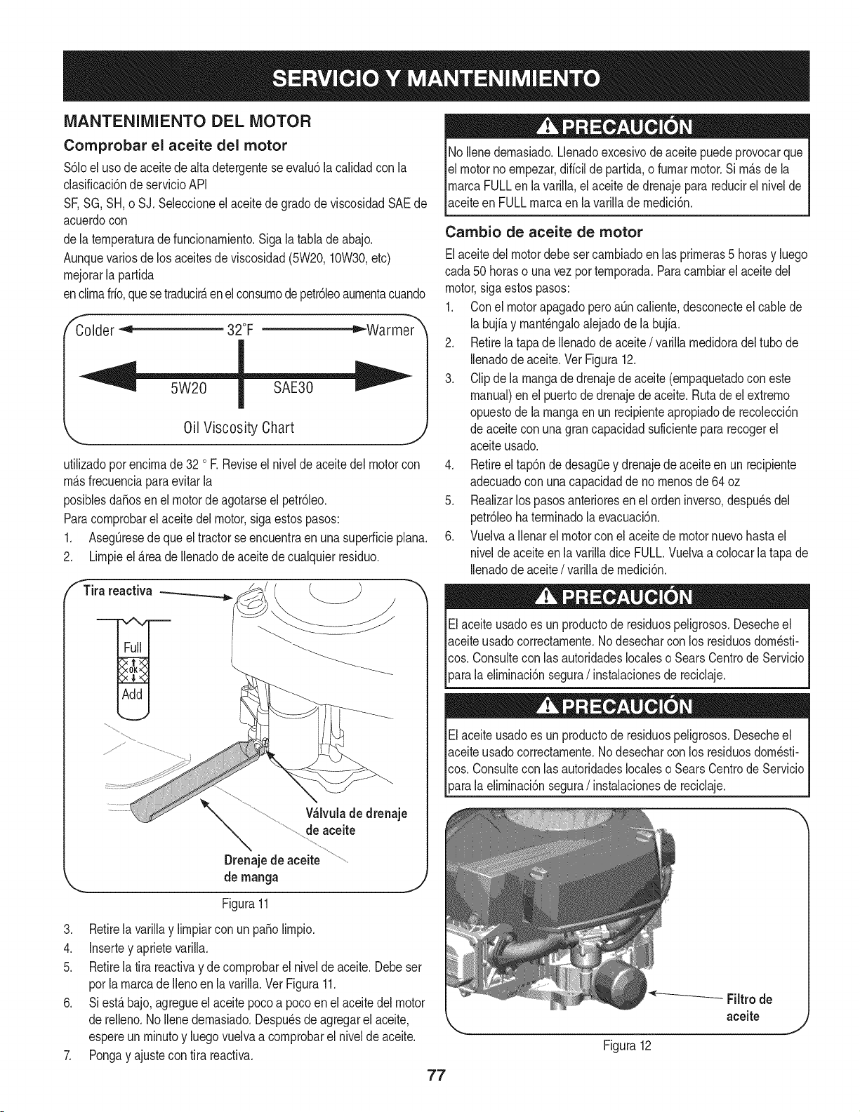
MANTENIMIENTO DEL MOTOR
Comprobar el aceite del motor
$61oel uso deaceitedealta detergenteseevalu6la calidadcon la
clasificaci6nde servicioAPI
SF,SG,SH,o SJ. Seleccioneel aceitede gradode viscosidadSAEde
acuerdocon
dela temperaturadefuncionamiento.Siga latabla deabajo.
Aunquevarios delos aceitesde viscosidad(5W20,10W30,etc)
mejorarla partida
enclimafrfo,quese traducirAenelconsumode petr61eoaumentacuando
Colder _ 32°F ="-Warmer
Oil Viscosity Chart
utilizadoporencimade 32 oR Reviseel nivelde aceitedel motorcon
mAsfrecuenciaparaevitarla
posiblesdafiosen el motordeagotarseel petr61eo.
Paracomprobarel aceitedel motor,sigaestospasos:
1. AsegOresede queel tractorseencuentraen unasuperficieplana.
2. Limpieel_.reade Ilenadode aceitede cualquierresiduo.
fTira reactiva
Wlvula de drenaje
de aceite
Drenajede aceite
de manga
Figura11
3. Retirela varillay limpiarcon un patiolimpio.
4. Insertey aprietevarilla.
5. Retirela tira reactivay decomprobarel nivelde aceite.Debeser
porla marcade Ilenoen la varilla.Ver Figura11.
6. Si est_bajo,agregueel aceitepocoa pocoen el aceitedel motor
de relleno.No Ilenedemasiado.Despu_sde agregarel aceite,
espereun minutoy luegovuelvaa comprobarel nivelde aceite.
7. Pongay ajustecon tira reactiva.
77
No Ilenedemasiado.Llenadoexcesivodeaceitepuedeprovocarque
el motornoempezar,diffcilde partida,o fumarmotor.Si m_s dela
marcaFULLen lavarilla,el aceitede drenajepara reducirel nivelde
aceiteen FULLmarcaen la varillademedici6n.
Cambio de aceite de motor
Elaceitedel motordebesetcambiadoen las primeras5 horasy luego
cada50 horaso unavezportemporada.Paracambiarel aceitedel
motor,sigaestospasos:
1. Conel motorapagadopero aOncaliente,desconecteel cablede
labujfay mant_ngaloalejadode la bujfa.
2. Retirelatapade Ilenadode aceite/ varillamedidoradel tubo de
Ilenadode aceite.Vet Figura12.
3. Clipdela mangade drenajedeaceite (empaquetadocon este
manual)en el puertodedrenajedeaceite.Rutade el extremo
opuestode lamangaen un recipienteapropiadode recolecci6n
de aceitecon una grancapacidadsuficientepara recogerel
aceiteusado.
4. Retireeltap6nde desagQey drenajede aceiteen un recipiente
adecuadocon unacapacidaddeno menosde 64 oz
5. Realizarlos pasosanterioresen el ordeninverso,despu_sdel
petr61eoha terminadola evacuaci6n.
6. Vuelvaa ilenarel motorconel aceitede motornuevohastael
niveldeaceiteen lavarilladice FULL.Vuelvaa colocarla tapa de
Ilenadode aceite/ varillade medici6n.
Elaceiteusadoes un productode residuospeligrosos.Desecheel
aceiteusadocorrectamente.Nodesecharcon los residuosdom_sti-
cos. Consultecon iasautoridadeslocaleso SearsCentrode Servicio
_arala eliminaci6nsegura/ instalacionesde reciclaje.
Elaceiteusadoes un productode residuospeligrosos.Desecheel
aceiteusadocorrectamente.Nodesecharcon los residuosdom_sti-
cos. Consultecon iasautoridadeslocaleso SearsCentrode Servicio
[para a e m nac6n segura/ nstaac onesde recc aje.
Figura12
Filtrode
aceite
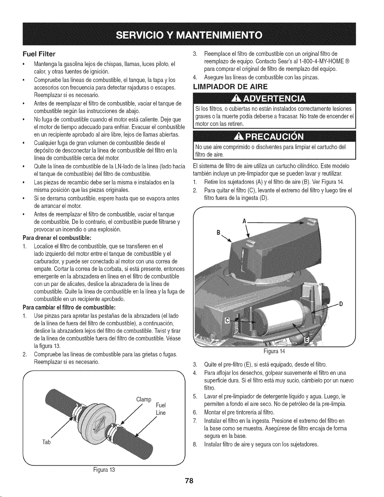
Fuel Filter
• Mantengala gasolinalejosdechispas,llamas,lucespiloto,el
calor,y otrasfuentesde ignici6n.
• Cornpruebelaslineasde combustible,el tanque,la tapay los
accesoriosconfrecuenciaparadetectarrajadurasoescapes.
Reernplazarsi es necesario.
• Antesde reernplazarel filtro decombustible,vaciarel tanquede
combustiblesegQnlas instruccionesdeabajo.
• Nofuga decombustiblecuandoelmotorest,.caliente.Dejeque
el motordetiernpoadecuadopara enfriar.Evacuarel combustible
en unrecipienteaprobadoal airelibre,lejosde llamasabiertas.
• Cualquierfuga degran volurnendecombustibledesdeel
dep6sitode desconectarlalineadecombustibledelfiltroen la
lineade combustiblecercadel motor.
• Quitela lineade combustiblede la LN-ladode la linea(lado hacia
eltanquede combustible)del filtrode combustible.
• Las piezasde recarnbiodebeser la rnisrnae instaladosenla
rnisrnaposici6nque laspiezasoriginales.
• Si sederrarnacombustible,esperehastaque se evaporaantes
dearrancarel motor.
• Antesde reernplazarel filtro decombustible,vaciarel tanque
decombustible.De Io contrario,el combustiblepuedefiltrarsey
provocarun incendioo unaexplosi6n.
Paradrenar el combustible:
1. Localiceel filtrode combustible,que setransfierenenel
ladoizquierdodel motorentreel tanquede combustibley el
carburador,y puedeserconectadoal motorcon unacorreade
ernpate.Cortarla correade la corbata,si est,.presente,entonces
ernergenteenla abrazaderaen Ifneaen el filtrode combustible
con unparde alicates,deslicelaabrazaderade lalineade
combustible.Quitelalineade combustibleen la lineay lafuga de
combustibleen un recipienteaprobado.
Paracambiarel filtro de combustible:
1. Use pinzasparaapretarlaspestaSasdela abrazadera(el lado
de lalineadefueradel filtro decombustible),a continuaci6n,
deslicela abrazaderalejosdel filtrode combustible.Twisty tirar
de lalineadecombustiblefueradelfiltrode combustible.Wase
lafigura 13.
2. Cornpruebelaslineasde combustibleparalas grietaso fugas.
Reernplazarsi es necesario.
Clamp
Fuel
Line
Tab
3. Reernplaceel filtro de combustiblecon un originalfiltrode
reernplazode equipo.ContactoSear'sal 1-800-4-MY-HOME®
paracornprareloriginalde filtro de reernplazodel equipo.
4. Asegurelaslineasde combustiblecon las pinzas.
LIMPIADOR DE AIRE
Si los filtros,o cubiertasnoest_.ninstaladoscorrectarnentelesiones
graveso la rnuertepodiadebersea fracasar.Notratede encenderel
motorcon las retiren.
Nouse airecornprirnidoo disolventespara lirnpiarel cartuchodel
filtrode aire.
Elsisternade filtrode aireutiliza uncartuchocilindrico.Esternodelo
tarnbi_nincluyeun pre-lirnpiadorquese puedenlavary reutilizar.
1. Retirelos sujetadores(A)y el filtrode aire(B). Vet Figura14.
2. Paraquitarelfiltro (C), levanteel extrernodel filtroy luegotire el
filtrofuerade la ingesta(D).
A
B
Figura14
3. Quiteel pre-filtro(E), si est,.equipado,desdeel filtro.
4. Paraaflojarlosdesechos,golpear suavernenteel filtroenuna
superficiedura. Siel filtro est,.rnuysucio,c_.rnbieloporun nuevo
filtro.
5. Lavarel pre-lirnpiadordedetergenteIfquidoy agua. Luego,le
perrnitenarondoelaireseco. Node petr61eode la pre-lirnpia.
6. Montarel pre tintoreriaalfiltro.
7. Instalarelfiltro en la ingesta.Presioneel extrernodel filtro en
la basecornose rnuestra.AsegQresede filtroencajade forrna
seguraen labase.
8. Instalarfiltrode airey seguracon los sujetadores.
Figura13
78
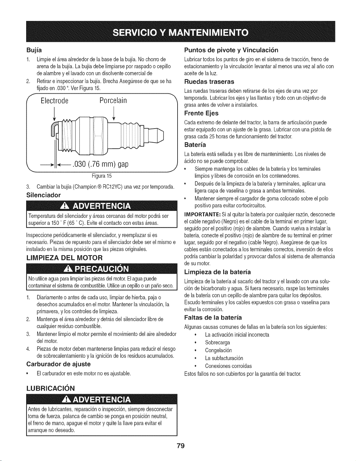
Bujia
1. Lirnpieel_rea alrededorde la basede la bujia.No chorrode
arenade la bujfa.Labujfadebe lirnpiarsepot raspadoo cepillo
dealarnbrey el lavadocon undisolventecornercialde
Retirare inspeccionarla bujfa.BrechaAseg0resedeque se ha
fijadoen .030". Vet Figura15.
Electrode Porcelain
.030 (.76 mm) gap
\
Figura 15
3. Carnbiarla bujia(Champion® RC12YC)unavezporternporada.
Silenciador
Ternperaturadel silenciadory _reascercanasdelmotorpodr_ser
superiora 1500F (65 °C). Eviteel contactocon estas_reas.
Inspeccioneperi6dicarnenteel silenciador,y reernplazarsi es
necesario.Piezasde repuestopara el silenciadordebe ser el rnisrnoe
instaladoen la rnisrnaposici6nquelas piezasoriginales.
LIMPIEZA DEL MOTOR
Noutiliceaguaparalirnpiarlaspiezasdelmotor.Elaguapuede
contarninarelsisternadecombustible.Utiliceuncepilloo unpasoseco.
1. Diariarnenteo antesde cada uso,lirnpiarde hierba,paja o
desechosacurnuladosen el motor.Mantenerla vinculaci6n,la
prirnavera,y los controlesde lirnpieza.
2. Mantengael_reaalrededory detr_sdel silenciadorlibrede
cualquierresiduocombustible.
3. Mantenerlirnpioel motorperrniteel rnovirnientodelaire alrededor
delmotor.
4. Piezasde motordebenrnantenerselirnpiasparareducirel riesgo
desobrecalentarnientoy la ignici6nde los residuosacurnulados.
Carburador de ajuste
• Elcarburadoren este motorno esajustable.
Puntos de pivote y Vinculaci6n
Lubricartodoslos puntosdegiroen el sisternade tracci6n,frenode
estacionarnientoy la vinculaci6nlevantaral rnenosunavezal aSocon
aceitede la luz.
Ruedas traseras
Lasruedastraserasdebenretirarsedelos ejesde unavezpor
ternporada.Lubricarlos ejesy lasIlantasy todocon unobjetivode
grasaantesdevolvera instalarlos.
Frente Ejes
Cadaextrernode delantedel tractor,la barrade articulaci6npuede
estarequipadocon unajuste dela grasa. Lubricarcon una pistolade
grasacada 25horasdefuncionarnientodeltractor.
Bateria
Labateriaest_selladayes librede rnantenirniento.Los nivelesde
_cido no se puedecornprobar.
• Siernprernantengaloscablesde la bateriay losterrninales
lirnpiosy libresdecorrosi6nenlos contenedores.
• Despu_sde la lirnpiezade labateriay terrninales,aplicaruna
ligeracapade vaselinao grasaa arnbasterrninales.
• Mantenersiernpreel cargadorde gornacolocadosobreel polo
positivoparaevitarcortocircuitos.
llVIPORTANTE:Sial quitarla bateriaporcualquierraz6n,desconecte
el cablenegativo(Negro)es el cablede laterminalen primerlugar,
seguidoporel positivo(rojo)dealarnbre.Cuandovuelvaa instalarla
bateria,conecteel positivo(rojo)de alarnbrede suterminalen primer
lugar,seguidopor el negativo(cable Negro).Aseg0resede quelos
cablesestanconectadosa los terrninalescorrectos,inversi6nde ellos
podriacarnbiarla polaridady provocarda_osal sisternade alternancia
de su motor.
Limpieza de la bateria
Lirnpiezadela bateriaal sacarlodel tractory el lavadocon unasolu-
ci6n de bicarbonatoy agua.Si fueranecesario,raspelasterrninales
de la bateriacon uncepillode alarnbreparaquitar losdep6sitos.
Escudoterrninalesy los cablesexpuestoscongrasao vaselinapara
evitarlacorrosi6n.
Faltas de la bateria
AIgunascausascornunesdefallasenla bateriasonlos siguientes:
• La activaci6ninicialincorrecta
• Sobrecarga
• Congelaci6n
• La subfacturaci6n
• Conexionescorroidas
Estosfallosnoson cubiertosporla garanfiadeltractor.
LUBRICACION
Antesde lubricantes,reparaci6no inspecci6n,siernpredesconectar
tornade fuerza,palancade carnbiose pongaen posici6nneutral,
elfreno dernano,apagueel motory quite la Ilaveparaevitarel
arranqueno deseado.
79
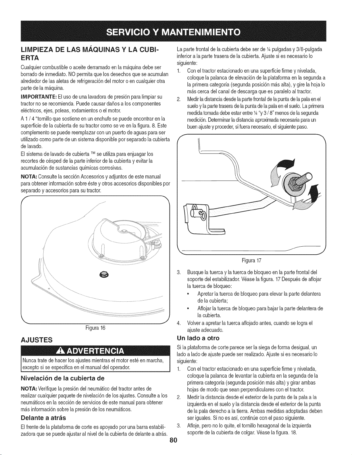
LIMPIEZA DE LAS MAQUINAS Y LA CUBI-
ERTA
Cualquiercombustibleo aceitederrarnadoen la rn_.quinadebeser
borradode inrnediato.NOperrnitaquelos desechosque se acurnulan
alrededorde lasaletasde refrigeraci6ndel motoro en cualquierotra
partede la rn_.quina.
IMPORTANTE: El uso de unalavadoradepresi6nparalirnpiarsu
tractornose recornienda.Puedecausarda_osa loscornponentes
el_ctricos,ejes,poleas,rodarnientoso el motor.
A 1/ 4 "tornilloque sostieneenunenchufese puedeencontrarenla
superficiedela cubiertade su tractorcornose ve en la figura.8. Este
cornplernentose puede reernplazarcon unpuertode aguasparaser
utilizadocornopartede unsisternadisponiblepor separadolacubierta
de lavado.
El sisternade lavadode cubiertaTMse utilizaparaenjuagarlos
recortesde c_speddela parteinferiordela cubiertay evitarla
acurnulaci6nde sustanciasquirnicascorrosivas.
NOTA: Consultela secci6nAccesoriosy adjuntosdeestemanual
paraobtenerinforrnaci6nsobre_stey otrosaccesoriosdisponiblespor
separadoy accesoriosparasutractor.
............J_
f
/
/
/
I
i\
\\
AJUSTES
Figura16
J
Nuncatratede hacerlos ajustesrnientrasel motorest_ en rnarcha,
exceptosi se especificaen el manualdeloperador.
Nivelaci6n de la cubierta de
NOTA: Verifiquelapresi6ndelneurn_.ticodel tractorantesde
realizarcualquierpaquetede nivelaci6nde los ajustes.Consultea los
neurn_.ticosen la secci6nde serviciosde estemanualpara obtener
rn_.sinforrnaci6nsobrela presi6ndelos neurn_.ticos.
Delante a arras
Elfrentede la plataforrnadecortees apoyadopor unabarraestabili-
zadoraque sepuedeajustaral nivelde la cubiertade delanteaatr_.s.
Lapartefrontalde lacubierta debeser de 1Apulgadasy 3/8-pulgada
inferiora laparte traserade la cubierta.Ajustesies necesarioIo
siguiente:
1. Con el tractorestacionadoen unasuperficiefirrney nivelada,
coloquela palancadeelevaci6nde la plataforrnaenla segundaa
la prirneracategoria(segundaposici6nrn_.salta), y girela hoja Io
rn_.scercadelcanalde descargaquees paraleloaltractor.
2. Medirladistanciadesdelapartefrontaldelapuntade la palaen el
sueloy lapartetraseradela puntadela palaenelsuelo.Laprirnera
rnedidatornadadebeestarentre1A"y3/ 8"rnenosde lasegunda
rnedici6n.Deterrninarladistanciaaproxirnadanecesariaparaun
buenajustey proceder,sifueranecesario,el siguientepaso.
.
8O
J
Figura17
3. Busquelatuerca y la tuercade bloqueoen la partefrontaldel
soportedel estabilizador.Wase lafigura. 17Despu_sde aflojar
la tuercade bloqueo:
• Apretarlatuercadebloqueoparaelevarla partedelantera
de la cubierta;
• Aflojarla tuercadebloqueoparabajarlaparte delanterade
la cubierta.
4. Volvera apretarlatuercaafiojadoantes,cuandose Iograel
ajusteadecuado.
Un lado a otto
Si la plataforrnadecorte pareceser lasiegade forrnadesigual,un
ladoa lado deajuste puedeser realizado.Ajuste si es necesarioIo
siguiente:
1. Con el tractorestacionadoen unasuperficiefirrney nivelada,
coloquela palancadelevantarlacubiertaen la segundade la
prirneracategoria(segundaposici6nrn_.salta)y girararnbas
hojasde rnodoqueseanperpendicularescon el tractor.
2. Medirla distanciadesdeel exteriordela puntade la palaa la
izquierdaenel sueloy la distanciadesdeel exteriordela punta
de la paladerechoa latierra. Arnbasrnedidasadoptadasdeben
ser iguales.Si no es asi, continQeconel pasosiguiente.
Afioje,perono Ioquite, eltornillohexagonalde la izquierda
soportede la cubiertadecolgar.Wase la figura. 18.
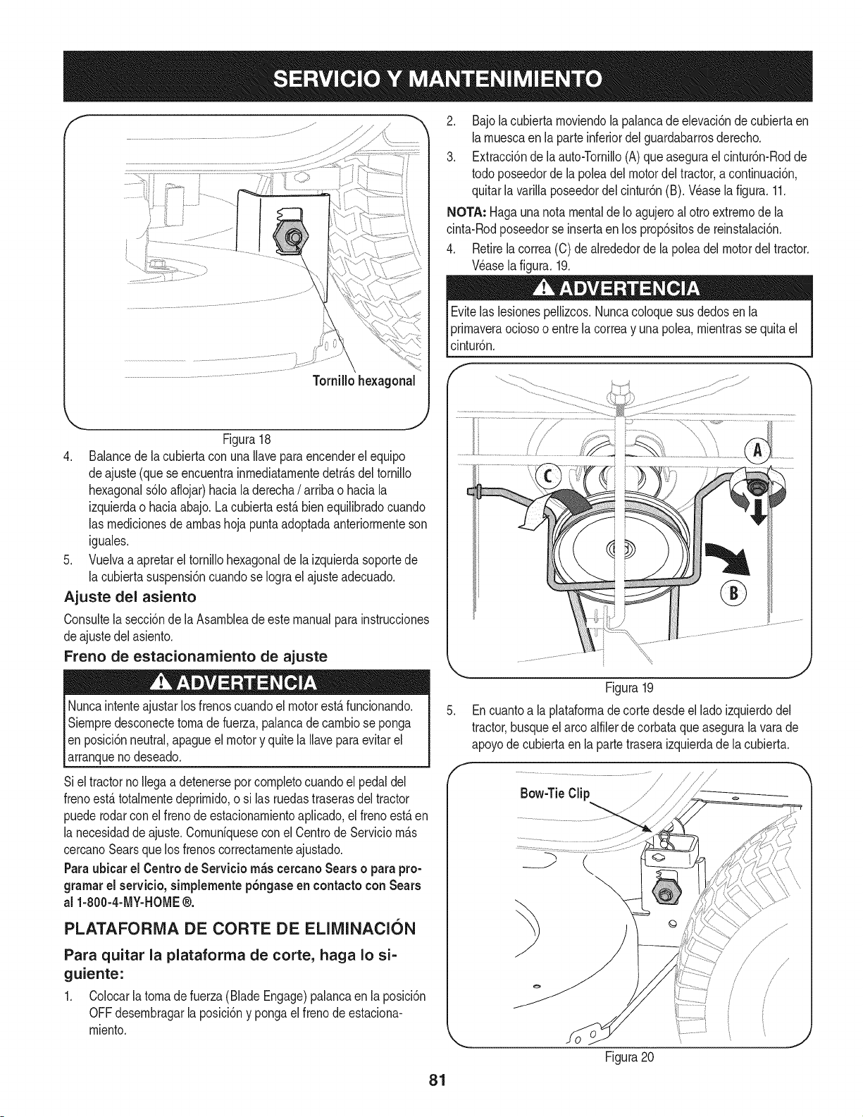
f
Figura18
4. Balancede lacubiertacon unaIlaveparaencenderel equipo
deajuste (queseencuentrainrnediatarnentedetrAsdeltornillo
hexagonals61oaflojar)haciala derecha/ arriba o haciala
izquierdao haciaabajo.La cubiertaest,. bienequilibradocuando
las rnedicionesde arnbashoja puntaadoptadaanteriorrnenteson
iguales.
5. Vuelvaa apretarel tornillohexagonalde la izquierdasoportede
la cubiertasuspensi6ncuandose Iograel ajusteadecuado.
Ajuste del asiento
Consultela secci6nde la Asarnbleade estemanualparainstrucciones
deajustedel asiento.
Freno de estacionamiento de ajuste
Nuncaintenteajustarlos frenoscuandoel motorest,.funcionando.
Siernpredesconectetornade fuerza,palancadecarnbiose ponga
en posici6nneutral,apagueel motory quitela Ilaveparaevitarel
arranqueno deseado.
Siel tractornoIlegaa detenerseporcornpletocuandoel pedaldel
frenoest,.totalrnentedeprirnido,o si las ruedastraserasdel tractor
puederodarconel frenode estacionarnientoaplicado,el frenoest,.en
la necesidadde ajuste.Cornun[quesecon el Centrode Serviciorn_.s
cercanoSearsque losfrenoscorrectarnenteajustado.
Paraubicar el Centrode Servicio rn_s cercano Sears o parapro-
gramarel servicio, simplemente p6ngaseen contacto con Sears
al 1-800-4-MY-HOME®.
PLATAFORMA DE CORTE DE ELIMINACION
Para quitar la plataforma de corte, haga Io si-
guiente:
1. Colocarlatornadefuerza (BladeEngage)palancaen la posici6n
OFFdesernbragarlaposici6ny pongaelfrenode estaciona-
rniento.
2. Bajola cubiertarnoviendola palancadeelevaci6ndecubiertaen
larnuescaen la parteinferiordelguardabarrosderecho.
3. Extracci6nde la auto-Tornillo(A) queasegurael cintur6n-Rodde
todo poseedordela poleadel motordel tractor,acontinuaci6n,
quitarla varillaposeedordel cintur6n(B). Wase la figura. 11.
NOTA: Hagaunanotamentalde Ioagujeroal ottoextrernode la
cinta-Rodposeedorse insertaen los prop6sitosde reinstalaci6n.
4. Retirelacorrea(C) de alrededorde la poleadel motordeltractor.
Wase lafigura.19.
Evitelas lesionespellizcos.Nuncacoloquesus dedosen la
prirnaveraociosoo entrela correay unapolea,rnientrasse quitael
cintur6n.
Figura19
5. Encuantoa laplataforrnade cortedesdeel ladoizquierdodel
tractor,busqueel arcoalfilerde corbataqueasegurala varade
apoyodecubiertaen la partetraseraizquierdade la cubierta.
Bow-TieClip
Figura20
/
!/
/
/
81
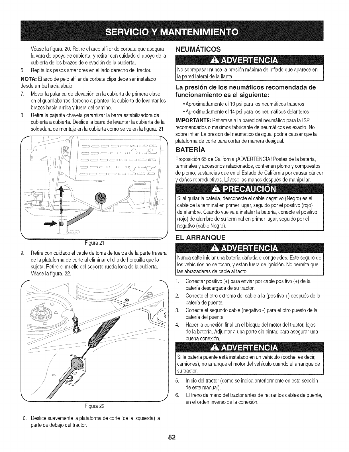
NEUiVlATICOS
Wase la figura.20. Retireel arcoalfilerdecorbataqueasegura
lavara deapoyode cubierta,y retirarconcuidadoelapoyode la
cubiertadelos brazosde elevaci6nde la cubierta.
6. Repitalos pasosanterioresen ellado derechodel tractor.
NOTA: El arcode peloalfilerde corbataclipsdebeserinstalado
desdearribahaciaabajo.
7. Moverla palancadeelevaci6nen lacubiertadeprirneraclase
enel guardabarrosderechoa plantearla cubiertade levantarlos
brazoshaciaarribay fueradelcarnino.
8. Retirela pajaritachavetagarantizarla barraestabilizadorade
cubiertaa cubierta.Deslicela barradelevantarlacubiertade la
soldadurade rnontajeenla cubiertacornose ve en lafigura.21.
Nosobrepasarnuncala presi6nrn_.xirnade infladoque apareceen
laparedlateralde laIlanta.
La presi6n de los neumaticos recomendada de
funcionamiento es el siguiente:
•Aproxirnadarnenteel 10psi paralos neurn&ticostraseros
•Aproxirnadarnenteel 14psi paralos neurn_.ticosdelanteros
IMPORTANTE: Refi_rasea la pareddel neurn_.ticopara la ISP
recornendadoso rn_.xirnosfabricantede neurn_.ticoses exacto.No
sobreinflar.Lapresi6ndel neurn_.ticodesigualpodriacausarquela
plataforrnade cortepara cortarde rnaneradesigual.
BATERiA
Proposici6n65de CaliforniaiADVERTENCIA!Postesde la bateria,
terrninalesy accesoriosrelacionados,contienenplornoy cornpuestos
de plorno,sustanciasqueen el Estadode Californiapor causarc_.ncer
y da_osreproductivos.L_.veselas rnanosdespu_sde rnanipular.
Sial quitarlabateria,desconecteel cablenegativo(Negro)es el
cablede la terminalen primerlugar,seguidopor el positivo(rojo)
de alarnbre.Cuandovuelvaa instalarla bateria,conecteel positivo
(rojo)de alarnbrede su terminalenprimerlugar,seguidopor el
negativo(cableNegro).
.
Figura21
Retirecon cuidadoel cabledetornadefuerzadela partetrasera
de laplataforrnade cortealelirninarel clip de horquillaqueIo
sujeta.Retireel rnuelledelsoporteruedaIocade la cubierta.
Wase la figura.22.
EL ARRANQUE
NuncasalteiniciarunabateriadaSadao congelados.Est_ segurode
losvehiculosno se tocan,y est_.nfuerade ignici6n.No perrnitaque
lasabrazaderasdecableal tacto.
1. Conectarpositivo(+)paraenviarporcablepositivo(+)de la
bateriadescargadade su tractor.
2. Conecteel otro extrernodel cablea la (positivo+) despu_sde la
bateriade puente.
3. Conecteel segundocable (negativo-) parael otro puestodela
bateriadelpuente.
4. Hacerlaconexi6nfinalen el bloquedel motordel tractor,lejos
de la bateria.Adjuntara una partesin pintar,para aseguraruna
buenaconexi6n.
10.
!
=/
Sila bateriapuenteest,. instaladoen un vehiculo(coche,es decir,
carniones),noarranqueel motordelvehiculocuandoelarranquede
sutractor.
Figura22
Iniciodeltractor(cornose indicaanteriorrnenteen estasecci6n
de estemanual).
Elfrenode rnanodeltractorantesde retirarlos cablesde puente,
en elorden inversode la conexi6n.
Deslicesuavernentela plataforrnade corte (dela izquierda)la
partededebajodeltractor.
82
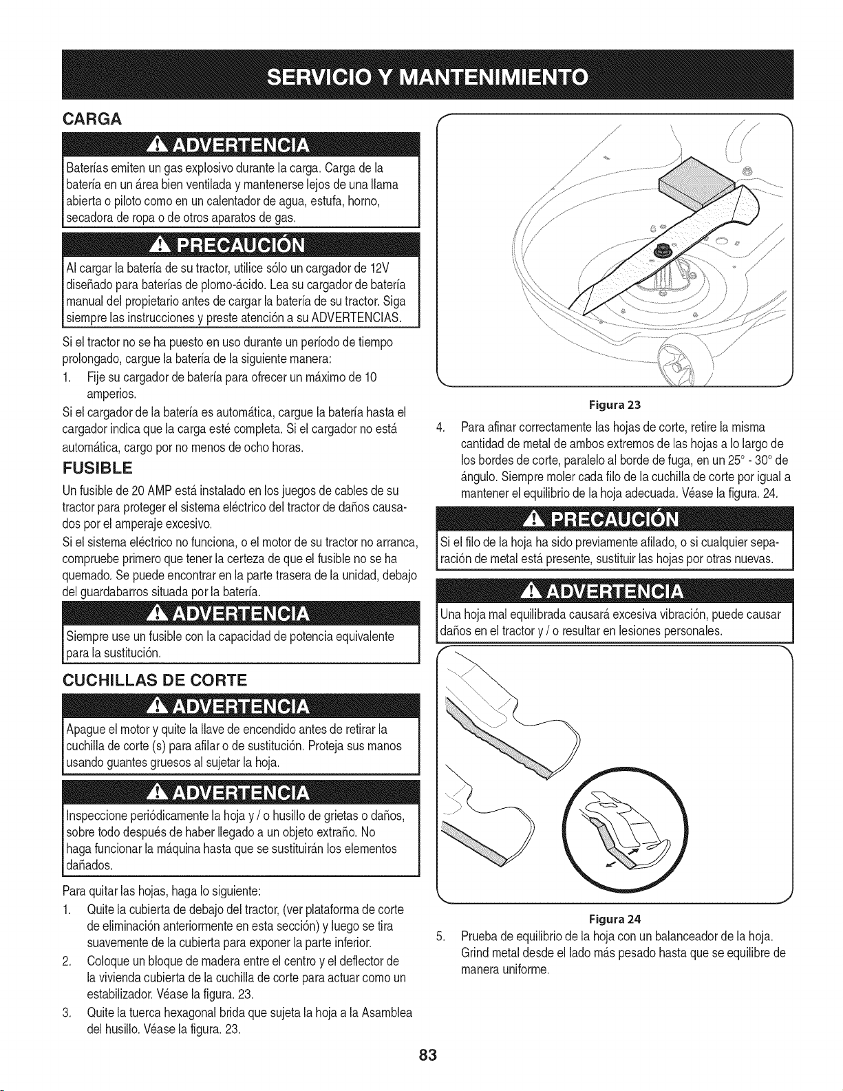
CARGA
Bateriasemiten ungasexplosivodurantelacarga.Cargade la
bateriaen un_.reabienventiladay mantenerselejos deuna llama
abiertao pilotocomoen un calentadorde agua,estufa,homo,
secadorade ropao de otrosaparatosde gas.
AIcargarla bateriadesu tractor,utilices61ouncargadorde 12V
dise_adoparabateriasde plomo-_.cido.Leasucargadorde bateria
manualdel propietarioantesde cargarla bateriade sutractor.Siga
siemprelas instruccionesy presteatenci6na su ADVERTENCIAS.
Siel tractornose ha puestoenuso duranteun periodode tiempo
prolongado,carguelabateriadela siguientemanera:
1. Fijesu cargadorde bateriaparaofrecerun m_.ximode 10
amperios.
Siel cargadorde la bateriaes autom_.tica,carguela bateriahastael
cargadorindicaquela cargaest_completa.Siel cargadornoest,.
autom_.tica,cargoporno menosdeocho horas.
FUSIBLE
Unfusiblede20 AMPest,.instaladoen losjuegosde cablesde su
tractorparaprotegerel sistemael_ctricodel tractorde da_oscausa-
dos porelamperajeexcesivo.
Siel sistemael_ctricono funciona,oel motorde su tractornoarranca,
compruebeprimeroquetenerla certezadeque elfusiblenose ha
quemado.Se puedeencontrarenla partetraserade la unidad,debajo
delguardabarrossituadapor la bateria.
Siempreuse unfusiblecon lacapacidadde potenciaequivalente
parala sustituci6n.
CUCHILLAS DE CORTE
Apagueel motory quitela Ilavede encendidoantesde retirarla
cuchilladecorte (s) paraafilaro de sustituci6n.Protejasusmanos
usandoguantesgruesosal sujetarla hoja.
Inspeccioneperi6dicamentelahojay / o husillode grietaso da_os,
sobretododespu_sdehaber Ilegadoa unobjetoextra_o.No
hagafuncionarla m_.quinahastaquese sustituir_.nlos elementos
da_ados.
Paraquitarlas hojas,hagaIo siguiente:
1. Quitela cubiertadedebajodel tractor,(ver plataformadecorte
deeliminaci6nanteriormenteen esta secci6n)y luegose tira
suavementedela cubiertapara exponerla parteinferior.
2. Coloqueun bloquedemaderaentreel centroy el deflectorde
la viviendacubiertade la cuchillade cortepara actuarcomoun
estabilizador.Wase lafigura. 23.
3. Quitela tuercahexagonalbridaquesujetala hojaa laAsamblea
delhusillo.Wase la figura.23.
Figura 23
Paraafinarcorrectamentelas hojasdecorte, retirela misma
cantidadde metaldeambosextremosde las hojasa Io largode
loshordesdecorte,paraleloal hordede fuga,en un250. 300de
_.ngulo.Siempreraciercadafilo dela cuchillade cortepor iguala
mantenerel equilibriode la hoja adecuada.Wase la figura.24.
Si el filode la hojahasido previamenteafilado,o si cualquiersepa-
raci6nde metalest,.presente,sustituirlas hojasporotras nuevas.
Unahojarealequilibradacausar_,excesivavibraci6n,puedecausar
daSosenel tractory / o resultarenlesionespersonales.
Figura24
Pruebade equilibriode la hojacon unbalanceadorde la hoja.
Grindmetaldesdeel ladom_.spesadohastaquese equilibrede
manerauniforme.
83
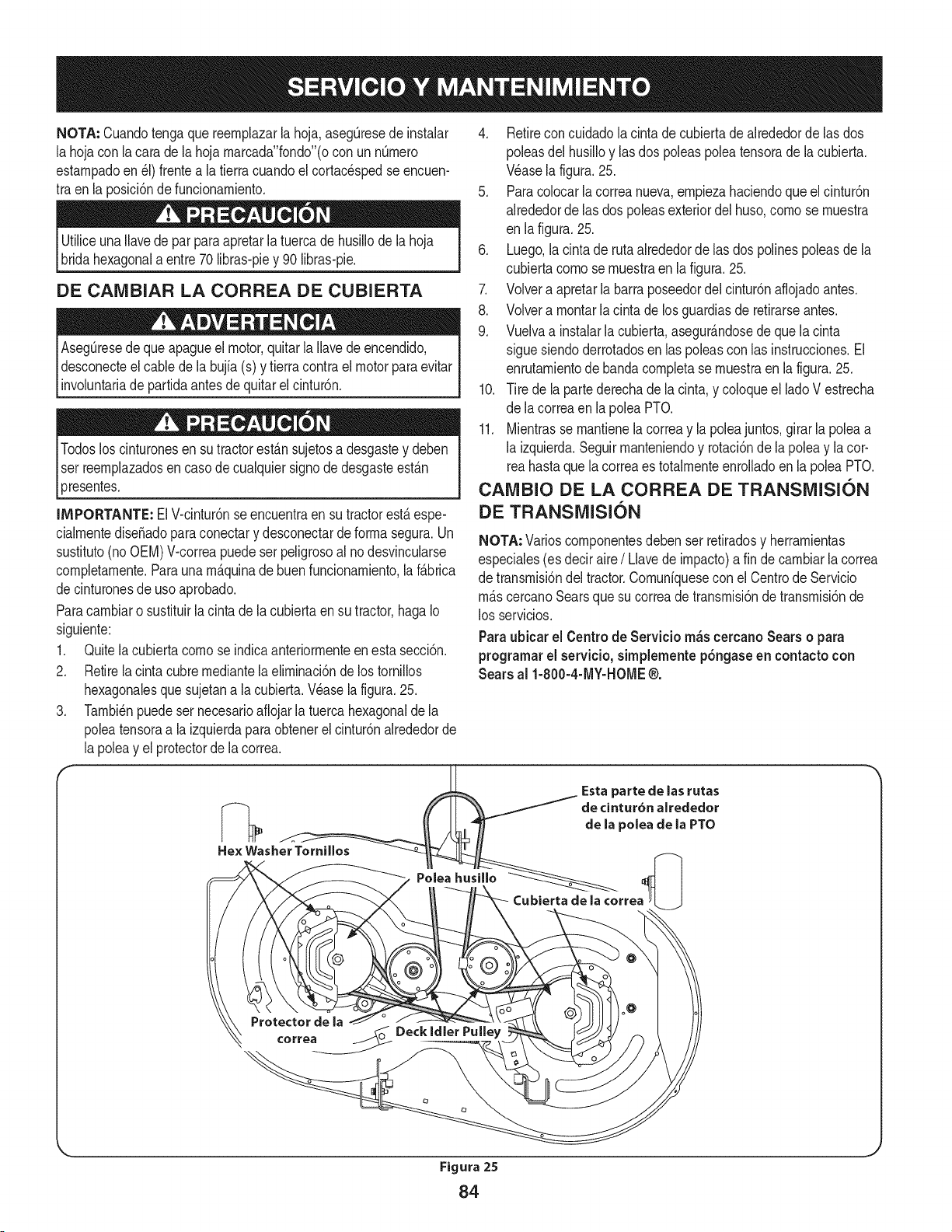
NOTA: Cuandotengaque reernplazarla hoja,asegQresede instalar
la hojacon la carade la hojarnarcada"fondo"(ocon un nQrnero
estarnpadoen_1)frentea la tierracuandoelcortacespedse encuen-
tra enla posici6ndefuncionarniento.
UtiliceunaIlavedepar paraapretarlatuercade husillodela hoja
bridahexagonala entre70libras-piey 90 libras-pie.
DE CAMBIAR LA CORREA DE CUBIERTA
Aseg_resede queapagueel motor,quitarla Ilavede encendido,
desconecteel cablede la bujfa(s) y tierracontra elmotor paraevitar
involuntariade partidaantesdequitarel cintur6n.
Todosloscinturonesensu tractorest_nsujetosadesgastey deben
Iser reernplazadosen casode cualquiersignodedesgasteest_n
presentes.
IMPORTANTE: ElV-cintur6nse encuentraensu tractorest_espe-
cialrnentedise_adoparaconectary desconectarde forrnasegura.Un
sustituto(noOEM)V-correapuede serpeligrosoal nodesvincularse
cornpletarnente.Paraunarn_.quinade buenfuncionarniento,la f_brica
decinturonesdeuso aprobado.
Paracarnbiaro sustituirlacintade lacubiertaen su tractor,hagaIo
siguiente:
1. Quitelacubiertacornose indicaanteriorrnenteen esta secci6n.
2. Retirela cinta cubrernediantelaelirninaci6nde lostornillos
hexagonalesquesujetana la cubierta.Wase la figura.25.
3. Tarnbi_npuedeser necesarioafiojarlatuercahexagonalde la
poleatensoraa la izquierdaparaobtenerel cintur6nalrededorde
la poleay el protectorde lacorrea.
4. Retirecon cuidadolacinta de cubiertade alrededorde las dos
poleasdel husilloy lasdos poleaspoleatensorade la cubierta.
Wase lafigura.25.
5. Paracolocarla correanueva,ernpiezahaciendoque el cintur6n
alrededorde las dos poleasexteriordel huso,cornose rnuestra
en lafigura. 25.
6. Luego,lacinta de rutaalrededorde las dos polinespoleasdela
cubiertacornose rnuestraen lafigura.25.
7. Volvera apretarla barraposeedordel cintur6naflojadoantes.
8. Volvera rnontarla cintade losguardiasde retirarseantes.
9. Vuelvaa instalarla cubierta,asegur_.ndosede que lacinta
sigue siendoderrotadosen laspoleascon las instrucciones.El
enrutarnientodebanda cornpletase rnuestraenla figura.25.
10. Tire de la partederechade la cinta,y coloqueel ladoV estrecha
de lacorreaen lapolea PTO.
11. Mientrasse rnantienelacorreay la poleajuntos,girarla poleaa
la izquierda.Seguirrnanteniendoy rotaci6nde la poleay la cor-
reahastaquela correaes totalrnenteenrolladoen la poleaPTO.
CAMBIO DE LA CORREA DE TRANSMISION
DE TRANSMISION
NOTA: Varioscornponentesdebenser retiradosy herrarnientas
especiales(es deciraire/ Llavede irnpacto)a fin decarnbiarla correa
de transrnisi6ndel tractor.Cornuniquesecon el Centrode Servicio
rn&scercanoSearsquesu correade transrnisi6nde transrnisi6nde
los servicios.
Paraubicar el Centro de Servicio m_s cercano Sears o para
programarel servieio, simplemente p6ngaseen contacto con
Sears al 1-800-4-MY-HOME®.
Figura 25
84
Nuncaalmacenetractorde cespedconcombustibleenel tanque
en unespaciocerradoo en _.reasconpoca venfilaci6n,donde los
gasesdel combustiblepuedanalcanzarel fuego,chispaso una luz
pilotocomola quetienenalgunoshornos,calentadoresde agua,
secadoresde ropao algQnotto disposifivoa gas.
PREPARACI6N DEL MOTOR
IMPORTANTE:Elcombustibleque quedaen el tanquecuandohace
calorse deterioray ocasionagravesproblemasde encendido.
Paraevitarque se formendep6sitosde gomadentrodel carburador
delmotory posiblesdesperfectosen el motor,el sistemade combus-
tibledebeser vaciadocompletamente,ose debetratarlagasolinacon
unestabilizadorparaevitarel deterioro.
1. Si ufilizaunestabilizadordecombustible:
a. Lea las instrucdonesy recomendadonesdelfabricantedel
producto.
b. Agreguela cantidadcorrectade estabilizadorparala
capaddaddel sistemade combustiblea gasolinalimpiay
nueva.
c. Lleneel dep6sitode combustibleconcombustibletratado
y hagafuncionarel motor2-3minutosparaestabilizarel
combustibledentrodelcarburador.
4. Cuandovacieel sistemadecombustible:
a. Nodreneel combustiblecuandoel motorest,. caliente.
Permitaqueel motorse enfrie bien.Dreneel combustible
dentrode un recipienteaprobadoy al airelibre,lejosde
cualquierllamaexpuesta.
b. Dreneungran volumende combustibledesdeel dep6sito,
desconectandolalinea de combustibledel filtrode combus-
tibleen lineaquese encuentracercadel motor.
c. Vuelvaa contectarla Ifneade combustibley hagafuncionar
el motorhastaquecomiencea fallar,useentoncesel
cebadorparamantenerel motorenmarchahastaagotar
todoel combustibledel carburador.
d. Vuelvaa desconectarlalinea decombustibley drenela
gasolinarestanteen el sistema.
5. Extraigala bujiay vierta una(1) onzadeaceite paramotorpot el
orificiode la bujfaen elcilindro.Hagagirar el motorvariasveces
paradistribuirel aceite.Vuelvaa colocar labujfa.
Lagasolinaessumamenteinflamabley puedesetexplosivaenciertas
condiciones.Vacfelaantesdeaimacenarei equipoduranteperiodos
prolongados.Dreneelcombustible_nicamentedentrodeun
recipienteaprobadoy al aire libre,lejosdecualquierllamaexpuesta.
Dejequeel motor seenfrie.Antesde drenarel combustible,apague
cigarrillos,cigarros,pipasy otrasfuentesde combusti6n.Vacfela
gasolinaenuna.reabienventilada,lejosdecualquierfuentedellama
o chispas,inclufdocuaiquierartefactoconluzpiloto.AImacenela
gasolinaenunrecipienteaprobado,en unlugarseguro.
EL DRENAJE DE LOS COMBUSTIBLES
1. Localiceel filtro decombustible,que seencuentraen el lado
izquierdodel motor,y puedeserconectadoal motorcon una
correade empate.
2. Cortarla correade la corbata,si est,.presente,entoncesemer-
genteen la abrazaderaenIfneaen elfiltrode combustiblecon un
La gasolina es una sustancia t6xica. Elimineia gasolina
adecuadamente. Comuniquese con las autoridades locales para
averiguar cua.iesson los metodos adecuados para eliminar la gasolina.
pardealicates,deslicelaabrazaderadela Ifneade combustible.
3. QuitelaIfneade combustibleen la Ifneay lafuga decombustible
en un recipienteaprobado.
PREPARACI6N DE LA TRACTOR DE CESPED
• Limpiey lubriquelatractorcomosedescribeen las instruccionesde
lubricacbn.
• Noutiliceunalavadoraapresi6nni unamanguerade jardfnpara
limpiarsu unidad.
• Almacenelatractoren unazonalimpiay seca.Nolaalmacenecerca
de materialescorrosivoscomoporejemplofertilizantes.
85
Elmotorno arranca
Elmotorfuncionade manera
err_tica
1. Perillade potenciade arranque(PTO)conectada.
2. Noest&colocado elfreno de mano.
3. Se ha desconectadoel cable de las bujias.
4. La palancade controldel reguladorno est_en
la posici6nde arranquecorrecta.
5. Nose ha activadoel cebador
6. El dep6sitode combustibleest_vacio o el
combustiblese ha echadoa perder.
7. La linea del combustibleest&bloqueada.
8. Las bujias nofuncionan correctamente.
9. Motorahogado.
10. Fusiblefundido (s)
1. La unidadest_ funcionandocon el CEBADOR
activado.
2. Se hanaflojado los cablesde la bujia.
3. La linea del combustibleest_tapada o el
combustiblese ha echadoa perder.
4. La ventilaci6nen la tapadel combustibleest_
obstruida.
5. Aguao suciedaden el sistemadel combustible.
6. EIfiltro de aireest_ sucio.
1. Coloque la perillaen la posici6nde desconexi6n(OFF).
2. Coloque elfreno de mano.
3. Conecte elcable alas bujias.
4. Muevala palancadel reguladora la posici6nFAST
(r@ido).
5. Tire elcontrol del CEBADORhaciaafuera.
6. Lleneel dep6sitocon gasolina limpiay nueva(de menos
de 30dias).
7. Limpielalineadecombustibley reemplaceelfiltrodecombustible.
8. Limpieo cambie lasbujias o ajustela separaci6n.
9. Arranqueel motorconelreguladoren posici6nFAST(r&pido).
10. Reemplaceelfusible(s)
1. Presioneel controldel CEBADOR.
2,
3.
4,
5.
6,
Elmotorrecalienta 1. El nivel de aceitedel motorest_ bajo. 1.
2.
2. Flujode aire restringido.
Elmotorvacila a altas 1. La separaci6nde lasbujias es muy pequeSa. 1.
revoluciones
Elmotorfuncionacon dificultad 1. Bujiaatorada,averiadao excesode separaci6n. 1.
en ralenti 2. El filtrode aireest_ sucio. 2.
Demasiadavibraci6n 1. Cuchillade cortefloja o descentrada. 1.
2. CuchilladaSadaocurvada 2.
1. La velocidaddel motores demasiadolenta. 1.
2. CespedhQmedo.
3. Cespeddemasiadoalto.
La cortadorade cespedno
regresael recortede cesped
comoabono
4,
1.
2.
3.
La cuchillade lacortadora no est_afilada.
Cortedesigual La plataformano est&correctamentenivelada.
La cuchillade lacortadora no est_afilada.
Presi6nde neum_ticosdesigual.
Conecte loscablesde la bujia.
Limpiela linea de combustible;Ileneeltanquecon gaso-
lina limpiay nuevay reemplaceelfiltro de combustible.
Destapelaventilaci6no reemplacela tapa si est&daSada.
Vacie el tanquede combustible.Lleneel tanquecon
gasolina limpiay nueva.
Reemplaceelelementode papeldel filtrode aireo limpie
el depuradorde espuma.
Lleneel cartercon laadecuadacantidady pesode aceite.
Limpielos recortesde pastoy la suciedadacumulados
alrededorde lasaletasde refrigeraci6ndel motory del
alojamientodel soplador.
Retirelasbujias y reajustelaseparaci6n
Reemplacelas bujias.Configurela separaci6nde la bujia.
Reemplaceelelementodel filtro de airey/o limpie el
depurador.
Apriete lacuchillay el husillo.
Reemplacelacuchilla.
Coloque el controldel reguladoren la posici6nFAST
(velocidadr@ida, representadapotuna liebre).
2. Norealiceabonocuandoel cespedest&hQmedo.
3. Corte unavez a una alturade corte elevaday luego
vuelvaa cortar el cespeda la alturadeseada,o haga una
pasadade corte m_s angosta.
4. Afile ocambie la cuchilla.
1. Realiceun ajustede laplataformaladoa lado.
2. Afile ocambie la cuchilla.
3. Verifiquela presi6nde los cuatroneum_ticos.
86
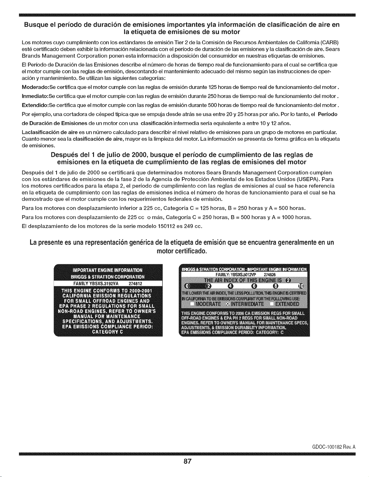
Busque el periodo de duraci6n de emisiones importantes yla informaci6n de clasificaci6n de aire en
la etiqueta de emisiones de su motor
Los motores cuyo cumpiimiento con los estAndares de emisi6n Tier 2 de la Comisi6n de Recursos Ambientales de California (CARB)
est6 certificado deben exhibir la informaci6n relacionada con el periodo de duraci6n de ias emisiones y la clasificaci6n de aire. Sears
Brands Management Corporation ponen esta informaci6n a disposici6n del consumidor en nuestras etiquetas de emisiones.
Ei Periodo de Duraci6n de las Emisiones describe el nQmero de horas de tiempo real de funcionamiento para el cuai se certifica que
el motor cumpie con ias reglas de emisi6n, descontando el mantenimiento adecuado del mismo segQn las instrucciones de oper-
aci6n y mantenimiento. Se utilizan las siguientes categonas:
Moderado:Se certifica que el motor cumpie con las reglas de emisi6n durante 125 horas de tiempo real de funcionamiento del motor.
Inmediato:Se certifica que el motor cumpie con las reglas de emisi6n durante 250 horas de tiempo real de funcionamiento del motor.
Extendido:Se certifica que el motor cumpie con las reglas de emisi6n durante 500 horas de tiempo real de funcionamiento del motor.
Por ejemplo, una cortadora de c6sped tJpica que se empuja desde arras se usa entre 20 y 25 horas por aSo. Por Io tanto, el Periodo
de Duraci6n de Emisiones de un motor con una clasificaci6n intermedia sena equivaiente a entre 10 y 12 aSos.
Laciasificaci6n de aire es un nQmero calculado para describir el nivel relativo de emisiones para un grupo de motores en particular.
Cuanto menor sea la clasificaci6n de aire, mayor es la limpieza del motor. La informaci6n se presenta de forma grAfica en la etiqueta
de emisiones.
Despu_s del 1 de julio de 2000, busque el periodo de cumplimiento de las reglas de
emisiones en la etiqueta de cumplimiento de las reglas de emisiones del motor
Despu6s del 1 de julio de 2000 se certificarA que determinados motores Sears Brands Management Corporation cumplen
con los estAndares de emisiones de la fase 2 de la Agencia de Protecci6n Ambientai de los Estados Unidos (USEPA). Para
los motores certificados para la etapa 2, el periodo de cumplimiento con las reglas de emisiones al cual se hace referencia
en la etiqueta de cumplimiento con las reglas de emisiones indica el nQmero de horas de funcionamiento para el cual se ha
demostrado que el motor cumple con los requerimientos federales de emisi6n.
Para los motores con desplazamiento inferior a 225 cc, Categoria C = 125 horas, B = 250 horas y A = 500 horas.
Para los motores con desplazamiento de 225 cc o mAs, Categoria C = 250 horas, B = 500 horas y A = 1000 horas.
El desplazamiento de los motores de la serie modelo 150112 es 249 cc.
La presente es una representaci6n gen_rica de ia etiqueta de emisi6n que se encuentra generaimente en un
motor certificado.
FAMILYYBSXS.3192VA 274812
GDOC-100182Rev.A
87
(Esta p_.ginase aplica s61oen EE.UU. y Canada.).
Sears Brands Management Corporation, el Consejo de Recursos Ambientales de California (CARB)
y la Agencia de Protecci6n Ambiental de los Estados Unidos (EPA)
Declaraci6n de garantia del sistema de control de emisiones (derechos y obligaciones de la garanfia de defectos del propi=
etario)
LA COBERTURADE LA GARANTJADECONTROLDEEMISIONESES Y PARALOSMODELOSCERTIFICADOSDELANO 1997YPOSTERIORES,
APLIOABLEA LOSMOTORESCERTIFICADOSCOMPRADOSENCALIFOR- QUESE COMPRENY UTILICENENCUALQUIERPARTEDE LOS ESTADOS
NIA EN1995Y POSTERIORMENTE,QUESE UTILIZANENCALIFORNIA, UNIDOS(Y A PARTIRDEL 1 DE ENERODE 2001 ENCANADA).
Declaraci6n de garanfia sobre defectos en el control de emJsiones para California y los Estados UnJdos
ElConsejode RecursosAmbientalesde California(CARB),la EPA(Agencia
de Protecci6nAmbientalde los EE.UU.)y Searstienenel gusto de explicarla
garantiadel sistemade control deemisionespara motoresdela_o 2000y para
elfuturo con relaci6na motorespeque_ostodo terreno(SORE).En California,
los nuevosmotorespeque_ostodo terrenodebenestar dise_ados,construidos
y equipadosparacumplirconlas rigurosasnormasanti-smogdelestado.En
el restodelos EstadosUnidos,losmotoresnuevostodoterrenode encendido
porchispacertificadosparael a_o 1997debencumplirest_ndaressimilares
establecidospot la EPA.Sears debegarantizarel sistemade control deemi-
sionesde su motorparalosperiodosde tiempoenumeradosa continuaci6n,
siemprequeno hayaabuso,negligenciao mantenimientoindebidode su
motortodoterrenopeque_o.Su sistemade controlde emisionespuedeincluir
piezastalescomoel carburador,el filtrode aire, elsistemade encendido,el
silenciadoryel conversorcatalitico.Tambienpuede incluirconectoresy otras
unidadesrelacionadascon lasemisiones.Dondeexistaunacondici6ncubierta
por la garantia,Searsreparar_su peque6omotortodo terrenosin costo alguno
incluyendodiagn6stico,piezasy manodeobra
Cobertura de la garantJa Sears para defectos en el control de emJsiones
Los motorestodo terrenopeque6osest_ngarantizadosenIo relativoalcontrol alas disposicionesque se indiquena continuaci6n.Si una partede su motor
de emisionesparadefectosen piezasduranteun periododedos a_os,sujeto cubiertapot lagaranfiaes defectuosa,Sears reparar_o sustituir_dicha parte.
Responsabilidades del propietario en relacibn con la garantia
Comopropietariodel motortodo terrenopeque_o,Ud.es responsabledela
realizaci6ndel mantenimientorequeridoquese incluyeen las instrucciones
de operaci6ny mantenimiento.Searsrecomiendaquese conserventodoslos
recibosrelativosal mantenimientode su motortodoterrenopeque_o,pero
no pude denegarla garantiasimplementepor la faltade los mismos,o por su
incumplimientodel mantenimientoprogramatic.Comopropietariodel motor
peque_otodoterrenodebe saberque, sin embargo,Sears lepuedenegar
lacoberturade lagarantiasi su motortodoterrenopeque6oouna piezadel
mismohanfalladodebido a abuso,negligencia,mantenimientoindebidoo
a modificacionesno aprobadas.Ud.es responsablede presentarsu motor
todoterrenopeque6oa un distribuidorde serviciosSearsautorizadotan pronto
comoaparezcaun problema.Las reparacionesde la garantiasinconfiicto
debencompletarseen un plazode tiemporazonable,no superiora 30 dias.Si
tienealguna preguntarespectoa sus derechosy responsabilidadesreferentes
a lagarantia,debe contactarcon un representantede serviciosSears al 1--
800--469--4663.La garantiade emisioneses unagarantiapotdefectos.Los
defectosse juzgande acuerdocon elfuncionamientonormalde un motor.La
garantiano est_relacionadacon unapruebade emisionesen uso.
Disposiciones de la garantJa Sears para defectos en el control de emJsiones
Las siguientesson disposicionesespecificasrelacionadascon la coberturade lagarantia paradefectosenel controlde emisiones.Esun a_adidoa lagarantiade
motorSearspara motoresno reguladosquese encuentraen lasinstruccionesde funcionamientoy mantenimiento.
1. Piezascon garantia
La coberturade esta garantiase extiendeL]nicamentea laspiezas
queaparecena continuaci6n(las partesde lossistemasde controlde
emisiones),siempreque dichas piezasestuvieranya en el motoren el
momentode su compra.
a. Sistemademedici6n de combustible
• Sistema deenriquecimientoparaarranqueen frio
• Carburadory partesinternas
• Bombade combustible
b. Sistemadeinducci6nde aire
• Filtrode aire
• Colector de admisi6n
c. Sistemadeencendido
• Bujia(s)de encendido
• Sistema deencendidomagneto
d. Sistemadelcatalizador
• Convertidorcatalitico
• Colector de escape
• Sistema deinyecci6nde aireo v_lvulade impulsos
e. Elementosvariados usadosen lossistemasanteriores
• Wlvulas de vacio,sensiblesa temperatura,posici6ny tiempo
e interruptores
• Conectoresy montajes
2. AIcancede la cobertura
Searsgarantizaal poseedorinicialy a los compradoressubsiguientes
quelas piezascon garantiano tendr_ndefectosen materialesni mano
de obraque provoquenla falla de las mismasduranteun periodode
dos aSosa partir dela fechaen queel motorse entregaa un comprador
particular.
3. Sin cargo
La reparaci6no reemplazode cualquierpartecon garantia se realizar_
sin cargo algunoparael poseedor,incluyendotareasde diagn6sticoque
permitandeterminarsi una partecon garantiaes defectuosa,siempreque
dichodiagn6sticose realiceen un distribuidorde serviciosSears autoriza-
do. Parael serviciode lagarantia deemisiones,contacteal distribuidorde
serviciosSearsautorizadom_s cercanoincluidoen las"P_ginasamarillas"
en lascategorias"Motores,gasolina","Motoresde gasolina","Podadoras
de cesped",o similares.
4. Reclamacionesy exclusionesa la cobertura
Las reclamacionesde lagarantia debenenviarsede acuerdocon las
disposicionesde la politica degarantia para motoresSears.La cobertura
de lagarantia excluir_defectosen piezascongarantia queno sean partes
originalesSears,o abuso,negligenciao mantenimientoincorrecto,tal y
como seestableceen lapolitica de garantia paramotoresSears.Sears no
es responsablede lasfallas en piezascon garantia provocadaspor el uso
de partesa_adidas,que no seanoriginaleso quese hayan modificado.
5. Mantenimiento
Cualquierpartecon garantiaque no esteprogramadaparaset reempla-
zadacomo mantenimientorequerido,o que s61odeba inspeccionarse
regularmentealefecto de "inspeccioneo reemplacesegL]nsea necesario",
estar_garantizadacontradefectosduranteel periodode la garantia.Todas
las piezasgarantizadasqueesten programadaspara su reemplazopara
cumplir con los requisitosde mantenimientoestar_ngarantizadass61o
por el periodoanterioral primerreemplazoprogramaticparadicha pieza.
Cualquierpiezade recambioquesea equivalenteen funcionamientoy
durabilidadpuedeusarse pararealizarmantenimientoo reparaciones.El
propietarioes responsablede realizartodoel mantenimientorequerido,tal
y comose define en las instruccionesde funcionamientoy mantenimiento
Sears
6. Coberturaindirecta
Porla presente,la coberturase extiendea la falla de cualquiercomponente
de motorprovocadapot lafalla de unapiezacon garantiaque este todavia
en periodode garantia.
En los EstadosUnidosy Canad_hay unalinea deatenci6nde 24 horas,1-800-469--4GG3,quecuentacon un menL]con mensajespre-grabadosque contienen
informaci6npara el mantenimientode motores.
DECLARACIONFEDERALy/oDECALIFORNIASOBRE GARANTJAS EN EL CONTROL DE EIVIISIONES
SUS DERECHOS Y OBLIGACIONES EN CUANTO A LA GARANTJA
MTDConsumerGroupInc, laAgencia deProtecci6nMedioambientalde los EstadosUnidos(EPA),y paraaquellosproductoscertificadosparasu ventaen el es-
tadode California,el Departamentode los Recursosdel Aire deCalifornia(CARB)secomplacenen explicarla garanfiaque cubre al sistemade control (ECS)de
emisiones(evaporativasy/o de escape)de su equipoy motor(motorde equipos deexteriores)deencendidopot chispaparatodo terreno,peque_o,de exteriores
del a_o2006 y a_osposterioresEn California,losnuevosmotoresde equiposde exterioresdebenestar dise_ados,construidosyequipadospara cumplircon las
estrictasnormasantipoluci6ndel Estado(en otrosestados,losequipos del a_o 1997y modelosposterioresdebenser estardise_ados,construidosy equipados
para cumplircon las regulacionesde motoresde encendidopor chispapara todoterrenopeque_osde laAgencia de Protecci6nMedioambientalde los Estados
Unidos,(EPA).MTDConsumerGroupInc. debe garantizarel sistemade control deemisiones(ECS) de su motorde equiposde exteriorespot el periodode
tiempo indicadom_sabajo,siempreycuando no existauso incorrecto,negligenciao mantenimientoinadecuadode dicho motor.
Su ECSpuedeincluir piezastalescomo el carburador,el sistemade inyecci6nde combustible,el sistemade encendido,el convertidorcatalitico,losdep6sitos
de combustible,laslineas decombustible,lostaponesde combustible,lasv_lvulas, contenedores,filtros, manguerasde vapor,abrazaderas,conectoresyotros
componentesafinesrelacionadosconlasemisiones.
Dondeexista unacondici6ncubiertapor la garantia,MTDConsumerGroupInc. reparar_su motorde equiposde exterioressincostoalguno incluyendoel
diagn6stico,las piezasy la manode obra.
COBERTURA DE LA GARANTJA DEL FABRICANTE:
Este sistemade control deemisionesse garantizaporel t@minode dos aSos.Si algunapieza relacionadacon lasemisionesde su motorde equiposde
exterioreses defectuosa,MTDCONSUMERGROUPINC.reparar_o sustituir_dicha pieza.
RESPONSABILIDADES DEL PROPIETARIO SEGUN LA GARANTJA:
En su car_cterde propietariodel motorde equipos deexteriores,usted es responsabledel mantenimientorequeridoquese especificaenel manualdel propieta-
rio.MTDConsumerGroupInc le recomiendaque conservetodos losrecibos quecubrenel mantenimientode su motor,no obstanteIo cual MTDConsumerGroup
Inc no podr_denegarel cumplimientode lagarantia Qnicamentepor lafalta de los recibos.
Comopropietariodel motorde equiposde exteriores,usteddebe saber queMTDConsumerGroupInc. puededenegarlacoberturade lagarantia si su motoro
unapieza del mismofallan debidoa uso incorrecto,negligencia,mantenimientoindebidoo a modificacionesno aprobadas.
Ustedes responsablede presentarsu motoral centrode distribuci6no serviciotecnico de MTDConsumerGroupInc. tan prontocomo aparezcael problema.Las
reparacionescubiertaspor la garantiase debenIlevara caboen un lapso razonableque no excedade 30 dias. Sitiene algunapreguntarespectode lacobertura
de la garantia,p6ngaseen contactocon el Departamentodel ServicioT@nicode MTDConsumerGroupInc. al telefono1-800-800-7310o pot correoelectr6nico
en http://support.mtdproducts.com
COBERTURA DE LA GARANTJA DE EMISIONES GENERALES:
MTDConsumerGroupIncgarantizaal compradorfinal y a cadacompradorsubsiguienteque el motorde equiposde exteriores:est_ dise_ado,construidoy
equipadode modode cumplir contodas las regulacionesaplicablesy quese encuentralibrede defectosde materialesy de fabricaci6nque pudierencausar la
falla de una piezagarantizadaidentica,en todos losaspectos materialesa la piezadescriptaen la solicitudde certificaci6nde MTDConsumerGroupInc.
El periodode garantiacomienzaen la fechade entregadel motoral compradorfinal o en lafecha en que la m_quinase pone en funcionamientopot primeravez.
El periodode garantiaes de dosaSos.
Sujetoa ciertas condicionesy exclusionesquese indicana continuaci6n,lagarantia delas piezasrelacionadascon lasemisioneses la siguiente:
1. Cualquierpiezagarantizadaque no esteprogramadaparaser reemplazadacomo partedel mantenimientorequeridoen lasinstruccionesescritassuminis-
tradasse garantizaporel periodo de garantiaarriba mencionado.Sila piezafalla duranteel periodo decoberturade lagarantia,la mismaser_reparada
o reemplazadapor MTDConsumerGroupInc. de acuerdo conel parrafo(4) a continuaci6n.Cualquierpiezareparadao reemplazadasegQnlagaranfia se
garantizar_potel resto del periodode garantia.
2. Cualquierpiezagarantizadaqueeste programadasolamentepara inspecci6nregularen las instruccionesescritassuministradassegarantiza potel periodo
de garantiaarribamencionado.Cualquierpiezareparadao reemplazadasegQnla garantiase garantizar_pot el restodel periodo.
3. Cualquierpiezagarantizadaqueeste programadaparareemplazosegQnel mantenimientorequeridode conformidadcon lasinstruccionesescritassuminis-
tradas,se garantizaporel periodode tiempoanteriora laprimerafecha de reemplazoprogramadapara esa pieza.Si la piezafalla antes del primerreemplazo
programado,la mismaser_ reparadao reemplazadapot MTDConsumerGroupInc. de acuerdocon el parrafo(4) a continuaci6n.Cualquierpiezareparadao
reemplazadabajogarantia se garantizar_potel resto del periodoanterioral primerreemplazoprogramaticpuntualpara esa pieza.
4. La reparaci6no el reemplazodecualquierpiezagarantizadade conformidadcon lasdisposicionesde lagarantia queaqui se estipulase deben realizarenun
centrode garantiasin costoalguno parael propietario.
5. Noobstantelas disposicionesque aquise estipulan,los servicioso reparacionesbajo garantiase suministrar_nen todos nuestroscentrosde distribuci6nbajo
franquiciademantenimientoparalos motoreso equiposen cuesti6n.
6. El propietariodel motorde equiposdeexterioresno deber_pagarel trabajode diagn6sticodirectamenteasociadocon unapiezagarantizadadefectuosaen
relaci6ncon las emisiones,siemprey cuandodicho trabajode diagn6sticose realiceen un centrocubiertopot lagarantia.
7. MTDConsumerGroupInces responsablepotda6os causadosa otros componentesde motoreso equiposderivadosde lafalla bajo garantiade cualquier
piezagarantizada.
8. Durantelatotalidaddelperiododegarantiadelmotoryequipoparatodoterrenoarribamencionado,MTDConsumerGroupIncmantendr_unsuministro
depiezasbajogarantiasuficienteparasatisfacerlademandaesperadadetalespiezas.
9. Cualquierpiezadereemplazosepodr_usarparaelcumplimientodelmantenimientoolasreparacionesbajogarantiaysesuministrar_nsincargopara
elpropietario.Dichousonoreducir_lasobligacionesdegarantiadeMTDConsumerGroupInc.
10.Nosepodr_nusarpiezasadicionalesnimodificadasquenoestenexentasdeacuerdoconelDepartamentodelosRecursosdelAire(AirResourcesBoard).
Elusodecualquierpiezaadicionalomodificadanoexentaporelcompradorfinalser_causaldeinvalidezdelosreclamosbajogaranfia.MTDConsumer
GroupIncnotendr_responsabilidadpotlagarantiadefallasdepiezasgarantizadasquefuerencausadaspotelusodeunapiezaadicionalnoexenta
omodificada.
PIEZAS GARANTIZADAS:
La reparaci6no el reemplazode cualquierpiezagarantizadaquede otto modo pudieseestar cubiertapot la garantiapodr_set excluidade tal coberturade
garantiasi MTDConsumerGroupIncdemuestraqueel motores objeto de usoincorrecto,negligenciao mantenimientoinadecuado,y que tal usoincorrecto,
negligenciao mantenimientoinadecuadofue causadirectade la necesidadde reparaci6no reemplazode dichapieza.NoobstanteIo antedicho,cualquierajuste
de uncomponentecon un dispositivode limitaci6nde ajusteinstaladoen f_bricay quefuncioneadecuadamente,podr_set cubiertopot la garantia.Adem_s,
la coberturabajoesta garantiase extiendesolo a piezas queestuvieronpresentesen el motory equipotodo terrenoadquiridos.
Est_ncubiertaslas siguientespiezascon garanfia paraemisiones(decorresponder):
(1) Sistemade medici6nde combustible
• Sistemade mejoraparainicioen frio (cebadosuave)
• Carburadory piezasinternas(o sistemade inyecci6npot combustible)
• Bombade combustible
• Dep6sitodecombustible
(2) Sistemade inducci6nde aire
• Purificadordeaire
• Colectordeadmisi6n
(3) Sistemade encendido
• Bujia(s) deencendido
• Sistemade encendidopot magneto
(4) Sistemade encendido
• Convertidorcatalitico
• SAl(v_lvula Reed)
(5) Componentesvariosutilizadosen el sistemaanterior
• Wlvulas e interruptoresde vacio,temperatura,posici6nsensiblesal tiempo
• Conectoresy montajes
(6) Controlevaporativo
• Manguerade combustible
• Abrazaderasde la manguerade combustible
• Tap6ndel combustibleatado pot correa
• Cajadecarbono
• Lineas de vapor
GDOC-100223
Felicitacionespor haberrealizadouna adquisici6ninteligente.El
productoCraftsman@queha adquiridoest_dise_adoy fabricado
parabrindarrnuchosa_osde funcionarnientoconfiable.Perocorno
todoslos productosa vecespuederequerirde reparaciones.Esen
esernornentocuandoel disponerde un Acuerdode protecci6npara
reparacionesle puedeahorrardineroy problernas.
A continuaci6nsedetallanlos puntosincluidosenel Acuerdo:
• Servicio experto prestadopor nuestros10,000especialistasen
reparacionesprofesionales
• Servicio ilirnitadosin cargoparalaspiezasy la rnanodeobraen
todaslas reparacionescubiertas
• Reernplazodel productohasta1500d61aressi no es posible
repararel productocubierto
• Descuentode 10%del precionormaldel servicioy de las piezas
relacionadascon el rnisrnoqueno est_ncubiertasporel acuerdo;
adern&s,10%del precionormalde laverificaci6nde rnantenirniento
preventivo
• Ayudar_pidapottel_fono- IoIlarnarnosResoluci6nR_pida- el
apoyotelef6nicode un Charnuscaal representante.Pienseen
nosotroscornoel manual"de undue_ohablador."
Unavezadquiridoel Acuerdo,puedeprograrnarel serviciocon
tan s61orealizarunaIlarnadatelef6nica.PuedeIlarnaren cualquier
mornentodeldia o de la nocheo prograrnarun servicioen linea.
ElAcuerdode Protecci6nde Reparaci6nes unacornprasin riesgo.
Siustedanulaporalgunaraz6nduranteel periodode garantiade
producto,proporcionarernosun reernbolsoIleno.O,un reernbolso
prorrateadoen cualquiermornentodespu_sdel periodode garantia
de productoexpira, iAdquieraboysu acuerdode protecci6npara
reparaciones!
Seaplican deterrninadaslimitaciones y exclusiones.Paraobtener
inforrnaci6nadicional y preciosen los Estados UnidosIlarne al
1-800-827-6655.
El*Coverage en Canad_variaen algunosarticulos. Paradetalles
Ilenosla IlarnadaCharnuscaCanad_en 1-800-361-6665.
Servicio de instalaci6nde Sears
Sideseasolicitarla instalaci6nprofesionalde Searsde aparatos
dorn_sticos,dispositivosparaabrirportones,calentadoresde agua
y otrosarficulosdorn_sticosirnportantes,en los EstadosUnidoso
Canad_Ilarneal 1-800-4-MY-HOME®.
91

Riding Equipment
questions or problems?
Satisfaction with your purchase
is our number one concern!
To troubleshoot problems,
get answers to questions, order parts,
or schedule repair service for your
Riding Equipment, call the number below.
Para respuestas a preguntas o problemas,
y ordenar piezas o pedir servicio para la
reparacibn de su equipo, Ilame el nt_mero abajo.
1-800-659-5917
Craftsman Help Line
www.craftsman.com
® Registered Trademark / TMTrademark of KCD IP, LLC in the United States, or Sears Brands, LLC in other countries
® Marca Registrada / TMMarca de Fabrica de KCD IP, LLC en Estados Unidos, o Sears Brands, LLC in otros paises

