perator's
I:RnFrSMRN°
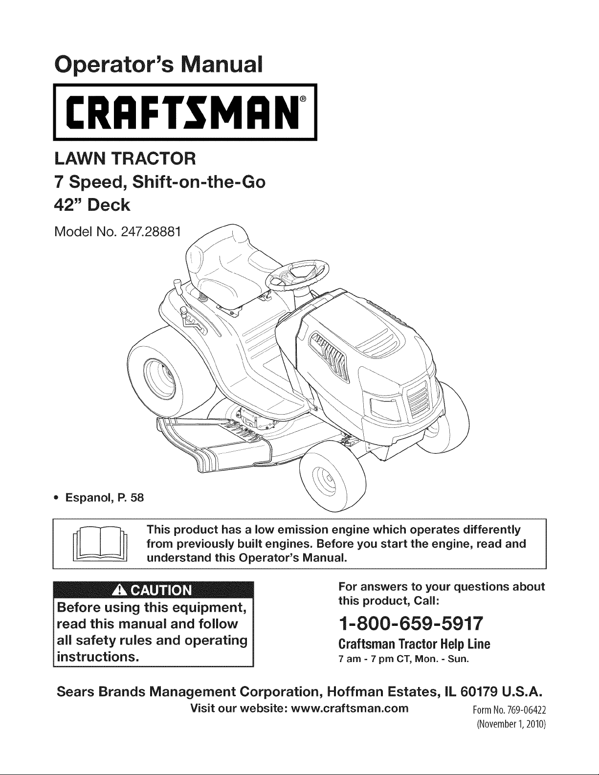
LAWN TRACTOR
7 Speed, Shift-on=the=Go
42" Deck
Model No. 247.28881
• Espanol, P. 58
This product has a low emission engine which operates differently
from previously built engines. Before you start the engine, read and
understand this Operator's Manual.
Before using this equipment,
read this manual and follow
all safety rules and operating
instructions.
For answers to your questions about
this product, Call:
1-800=659=5917
Craftsman Tractor Help Line
7 am = 7 pm CT, Mort. =Sun.
Sears Brands Management Corporation, Hoffman Estates, IL 60179 U.S.A.
Visit our website: www.craftsman.com FormNo.769-06422
(November1,2010)
Off-Season Storage ........................................................ 27
Trou bleshooting .............................................................. 28
Labels ............................................................................. 29
Parts List ......................................................................... 30
Espafiol ............................................................................ 57
Service Numbers ............................................. Back Cover
CRAFTSMAN TWO YEAR FULL WARRANTY
FORTWOYEARSfromthe dateof purchase,ifany non-expendablepart of this ridingequipmentfailsdueto a defectinmaterialor workman-
ship,visit www.craftsman.com or call 1-800-659-5917to arrangefor free in-homerepair.
Theframe and frontaxle will be repairedfreeof chargefor fiveyearsfromthe dateof purchaseif defectiveinmaterialor workmanship.
In all cases, if repairprovesimpossible,the ridingequipmentwill be replacedfree of chargewith the sameoran equivalentmodel.
The batterywill be replacedfree of chargefor 90 daysfrom the dateof purchaseifdefectivein materialor workmanship(our testingprovesthat it
will notholda charge).
Thiswarrantyisvoid ifthis productiseverusedwhile providingcommercialservicesor ifrentedto anotherperson.
This warranty covers ONLYdefects in material andworkmanship. Warranty coverage does NOTinclude:
• Expendableitemsthatcan wearoutfrom normalusewithinthewarrantyperiod,includingbut not limitedto blades,spark plugs,air
cleaners,belts,and oil filters.
o
o
o
o
Standardmaintenanceservicing,oilchanges,or tune-ups.
Tire replacementor repaircausedby puncturesfrom outsideobjects,such as nails,thorns,stumps,or glass.
Tireor wheelreplacementor repairresultingfromnormalwear,accident,orimproperoperationor maintenance.
Repairsnecessarybecauseof operatorabuse,includingbutnot limitedto damagecausedby towingobjectsbeyondthe capabilityof
the ridingequipment,impactingobjectsthatbendthe frameor crankshaft,or over-speedingthe engine.
Repairsnecessarybecauseof operatornegligence,includingbut not limitedto,electricaland mechanicaldamagecausedby improper
storage,failureto usethe propergradeandamountof engineoil, failureto keepthe deckclearof flammabledebris,orfailureto
maintainthe ridingequipmentaccordingto the instructionscontainedin the operator'smanual.
Engine(fuelsystem)cleaningor repairscausedbyfuel determinedto be contaminatedor oxidized(stale).In general,fuel shouldbe
usedwithin30 daysof its purchasedate.
Normaldeteriorationandwearof the exteriorfinishes,or productlabel replacement.
Thiswarrantygivesyou specificlegal rights,and you mayalso haveotherrightswhichvaryfromstateto state.
Sears Brands ManagementCorporation, HoffmanEstates, IL 60179
EngineOil: SAE30
Fuel: UnleadedGasoline
SparkPlug: Champion®RC12YC
Engine: Briggs& StrattonI/C®
Model Number:
Serial Number:
Dateof Purchase:
Recordthe modelnumber,serialnumber,
anddateof purchaseabove.
© KCD IR LLC 2
Thissymbolpointsout importantsafetyinstructionswhich,if not
followed,couldendangerthepersonalsafetyand/orpropertyof
yourselfandothers. Readandfollowall instructionsin thismanual
beforeattemptingto operatethis machine.Failureto complywith
theseinstructionsmayresultin personalinjury.Whenyou seethis
symbol,HEEDITSWARNING!
CALIFORNIA PROPOSITION 65
EngineExhaust,someof its constituents,andcertainvehicle
componentscontainoremit chemicalsknownto Stateof California
to cause cancerand birthdefectsor other reproductiveharm.
Batteryposts,terminals,and relatedaccessoriescontainleadand
leadcompounds,chemicalsknownto the Stateof Californiato
causecancerand reproductiveharm.Washhandsafter handling.
Thismachinewasbuiltto be operatedaccordingto the safeopera-
tion practicesin this manual.As withanytype of powerequipment,
carelessnessorerroron the partof the operatorcan resultin serious
injury.Thismachineis capableof amputatingfingers,hands,toes
andfeet and throwingdebris.Failureto observethe followingsafety
instructionscouldresultin seriousinjuryor death.
Your Responsibility--Restrictthe use of thispowermachineto
personswho read,understandand follow thewarningsand instruc-
tionsin this manualand on the machine.
SAVE THESE INSTRUCTIONS!
GENERAL OPERATION
• Read,understand,andfollowall instructionson the machineand
in themanual(s)beforeattemptingto assembleandoperate.
Keepthis manualina safe placefor futureand regularreference
andfor orderingreplacementparts.
• Befamiliarwithall controlsandtheir properoperation.Knowhow
to stop the machineanddisengagethemquickly.
• Neverallowchildrenunder14yearsoldto operatethis machine.
Children14yearsoldand over shouldreadand understandthe
operationinstructionsandsafetyrulesin this manualandshould
betrainedandsupervisedbya parent.
• Neverallowadultsto operatethis machinewithoutproper
instruction.
• Tohelpavoidbladecontactor a thrownobjectinjury,keep
bystanders,helpers,childrenand pets at least75feetfromthe
machinewhile it is in operation.Stopmachineif anyoneenters
the area.
• Thoroughlyinspectthe area wherethe equipmentis to be used.
Removeallstones,sticks,wire,bones,toys,and otherforeign
objectswhichcouldbe pickedupand thrownby the blade(s).
Thrownobjectscan causeseriouspersonalinjury.
• Planyour mowingpatternto avoiddischargeof materialtoward
roads,sidewalks,bystandersandthe like.Also, avoiddischarg-
ingmaterialagainstawall orobstructionwhichmaycause
dischargedmaterialto ricochetbacktowardthe operator.
• Alwayswear safetyglassesor safetygogglesduringoperation
andwhile performingan adjustmentor repairto protectyoureyes.
Thrownobjectswhich ricochetcancauseseriousinjuryto the
eyes.
• Wearsturdy,rough-soledworkshoesandclose-fittingslacksand
shirts.Loosefittingclothesandjewelry canbe caughtin movable
parts.Neveroperatethismachinein bare feet or sandals.
• Beawareof the mowerandattachmentdischargedirectionand
do not pointit at anyone.Donot operatethe mowerwithoutthe
dischargecoverorentiregrass catcherin its properplace.
Donot put handsor feet near rotatingpartsor underthe cutting
deck. Contactwith the blade(s)can amputatehandsandfeet.
A missingor damageddischargecovercan causeblade contact
or thrownobjectinjuries.
• Stoptheblade(s)whencrossinggraveldrives,walks,or roads
andwhile notcuttinggrass.
• Watchfor trafficwhenoperatingnear or crossingroadways.This
machineis not intendedfor useonany public roadway.
• Donot operatethe machinewhile underthe influenceof alcohol
or drugs.
• Mowonly in daylightor good artificiallight.
Nevercarrypassengers.
• Disengageblade(s)beforeshiftinginto reverse.Backup slowly.
Alwayslookdownandbehindbeforeandwhile backingto avoida
back-overaccident.
3
• Slowdownbeforeturning.Operatethe machinesmoothly.Avoid
erraticoperationandexcessivespeed.
Disengageblade(s),setparkingbrake,stopengineand wait until
the blade(s)come to a completestopbeforeremovinggrass
catcher,emptyinggrass,uncloggingchute,removinganygrassor
debris,or makinganyadjustments.
Neverleavea runningmachineunattended.Alwaysturnoff
blade(s),setparkingbrake,stopengineand removekey before
dismounting.
Useextracare whenloadingorunloadingthe machineintoa
traileror truck. This machineshouldnot bedrivenupor down
ramp(s),becausethe machinecouldtip over,causingserious
personalinjury.The machinemustbe pushedmanuallyon
ramp(s)to loador unloadproperly.
Mufflerandenginebecomehotandcan causea burn.Do not
touch.
Checkoverheadclearancescarefullybeforedrivingunderlow
hangingtree branches,wires,door openingsetc., wherethe
operatormaybe struckor pulledfrom the machine,whichcould
resultinseriousinjury.
Disengageallattachmentclutchesanddepressthe brakepedal
completelybeforeattemptingto start engine.
Yourmachineisdesignedto cut normalresidentialgrass of a
heightno morethan 10".Do not attemptto mowthroughunusually
tall,dry grass (e.g.,pasture)or piles of dry leaves.Drygrass or
leavesmaycontactthe engineexhaustand/or buildup on the
mowerdeckpresentinga potentialfire hazard.
Useonlyaccessoriesand attachmentsapprovedfor this machine
by the machinemanufacturer.Read,understandandfollowall
instructionsprovidedwiththe approvedaccessoryor attachment.
Fora list of approvedaccessoriesandattachments,call 1-800-
659-5917.
Dataindicatesthatoperators,age60 years and above,are
involvedin a largepercentageof riding mower-relatedinjuries.
Theseoperatorsshouldevaluatetheirabilityto operatethe riding
mowersafelyenoughto protectthemselvesandothersfrom
seriousinjury.
If situationsoccurwhicharenot coveredinthismanual,usecare
andgoodjudgment.Contact1-800-659-5917for informationand
assistance.
SLOPE OPERATION
Slopesare a majorfactorrelatedto lossof controlandtip-over
accidentswhichcan result in severeinjuryor death.All slopes require
extracaution.Ifyoucannotback up the slopeor if youfeel uneasyon
it, do not mowit.
Foryoursafety,use the SlopeGuideincludedas partof this manual
to measureslopesbeforeoperatingthis machineona slopedor hilly
area. If the slopeis greaterthan15degreesas shownonthe Slope
Guide,do notoperatethis machineonthat area or seriousinjurycould
result.
Do:
o
Mowupand down slopes,not across.Exerciseextremecaution
whenchangingdirectionon slopes.
• Watchfor holes,ruts,bumps,rocks,orother hiddenobjects.
Uneventerraincouldoverturnthe machine.Tallgrasscan hide
obstacles.
Useslowspeed.Choosea lowenoughspeedsettingso that
you will nothaveto stopor shiftwhileon the slope.Tires may
lose tractionon slopeseventhoughthe brakesare functioning
properly.Alwayskeepmachinein gearwhen goingdownslopes
to take advantageof enginebrakingaction.
• Followthe manufacturer'srecommendationsfor wheelweights
or counterweightsto improvestability.Forrecommendations,call
1-800-659-5917.
• Useextracarewith grass catchersor otherattachments.These
can changethe stabilityof the machine.
Keepallmovementonthe slopesslowandgradual.Do not make
suddenchangesin speedor direction.Rapidengagementor
brakingcouldcausethe frontof the machineto lift and rapidlyflip
overbackwardswhich couldcauseseriousinjury.
• Avoidstartingorstoppingona slope. If tires losetraction,disen-
gagethe blade(s)and proceedslowlystraightdownthe slope.
DoNot:
• Donot turnon slopesunlessnecessary;then, turnslowlyand
graduallydownhill,if possible.
• Donot mowneardrop-offs,ditchesor embankments.The mower
could suddenlyturnover if a wheelis overthe edgeof a cliff,
ditch,or if an edgecavesin.
• Donot try to stabilizethe machineby puttingyourfooton the
ground.
• Donot usea grass catcheron steepslopes.
• Donot mowon wetgrass.Reducedtractioncouldcausesliding.
• Donot attemptto coastdownhill.Over-speedingmaycausethe
operatorto lose controlof the machineresultingin seriousinjury
or death.
• Donot towheavypull behindattachments(e.g.loadeddumpcart,
lawn roller,etc.)on slopesgreaterthan5 degrees.Whengoing
down hill,the extraweighttendsto pushthe tractorandmay
causeyou to loosecontrol (e.g.tractormayspeedup, brakingand
steeringabilityare reduced,attachmentmayjack-knifeand cause
tractorto overturn).
4
CHILDREN
Tragicaccidentscanoccur ifthe operatoris notalert to the presence
of children.Childrenare often attractedto the machineand the mowing
activity.Theydo notunderstandthe dangers.Neverassumethat
childrenwill remainwhereyou lastsawthem.
• Keepchildrenout of the mowingareaand inwatchfulcare of a
responsibleadultotherthanthe operator.
• Bealert and turnmachineoff ifa childentersthe area.
• Beforeandwhilebacking,lookbehindand downfor small
children.
Nevercarrychildren,evenwith the blade(s)shut off.Theymay
fall off and be seriouslyinjuredor interferewithsafemachine
operation.
• Useextremecarewhenapproachingblindcorners,doorways,
shrubs,treesor otherobjectsthat may block yourvisionof a child
whomay run intothe machine.
Toavoidback-overaccidents,alwaysdisengagethe cutting
blade(s)beforeshiftingintoReverse.If equipped,the "Reverse
CautionMode"(bladesoperatewhilemachineridesin reverse)
shouldnotbe usedwhenchildrenor othersarearound.
Keepchildrenaway from hotor runningengines.They cansuffer
burnsfroma hotmuffler.
• Removekeywhenmachineisunattendedto preventunauthorized
operation.
Neverallowchildrenunder 14 yearsof ageto operatethis machine.
Children14andovershouldreadand understandthe instructionsand
safeoperationpracticesin this manualand on the machineand should
betrainedandsupervisedbyan adult.
TOWING
Towonlywith a machinethat hasa hitch designedfor towing.Do
not attachtowedequipmentexceptat the hitchpoint.
Followthe manufacturersrecommendationforweight limitsfor
towedequipmentandtowingon slopes.For recommendations,
call 1-800-659-5917.
Neverallowchildrenor othersin or on towedequipment.
Onslopes,theweightof thetowedequipmentmaycauselossof
tractionandloss of control.
Alwaysuseextra cautionwhentowingwitha machinecapableof
makingtightturns (e.g."zero-turn"ride-onmower). Makewide
turnsto avoidjack-knifing.
Travelslowlyand allowextradistanceto stop.
Do notcoastdownhill.
SERVICE
SafeHandlingof Gasoline
Toavoidpersonalinjuryorpropertydamageuse extremecarein
handlinggasoline.Gasolineisextremelyflammableand the vaporsare
explosive.Seriouspersonalinjurycanoccur whengasolineis spilled
on yourselforyour clotheswhich can ignite.Washyourskinand
changeclothesimmediately.
• Useonly an approvedgasolinecontainer.
Neverfill containersinsidea vehicleor on a truckortrailer bed
witha plasticliner.Alwaysplacecontainerson the groundaway
fromyourvehiclebeforefilling.
Whenpractical,removegas-poweredequipmentfrom the truck
or trailerand refueliton theground.Ifthis isnot possible,then
refuelsuchequipmentona trailerwitha portablecontainer,rather
than froma gasolinedispensernozzle.
Keepthe nozzleincontactwith the rim of the fueltankor
containeropeningat all timesuntilfuelingiscomplete.Donot use
a nozzlelock-opendevice.
Extinguishall cigarettes,cigars,pipesandothersourcesof
ignition.
• Neverfuel machineindoors.
Neverremovegascap or addfuelwhilethe engineis hotor run-
ning.Allowengineto coolat leasttwominutesbeforerefueling.
Neveroverfill fuel tank. Filltank to no morethan 1/2inchbelow
bottomof filler neckto allowspaceforfuel expansion.
• Replacegasolinecap and tightensecurely.
• Ifgasolineis spilled,wipeitoff the engineandequipment.Move
machineto anotherarea.Wait5 minutesbeforestartingthe
engine.
• To reducefire hazards,keepmachinefree of grass,leaves,or
otherdebrisbuild-up.Cleanup oilor fuel spillageandremoveany
fuel soakeddebris.
• Neverstorethe machineor fuelcontainerinsidewherethere isan
openflame,sparkor pilotlight as on a waterheater,spaceheater,
furnace,clothesdryeror othergasappliances.
Allowa machineto coolat leastfiveminutesbeforestoring.
GeneralService
• Neverrunanengineindoorsorinapoorlyventilatedarea.Engine
exhaustcontainscarbonmonoxide,anodorless,anddeadlygas.
• Beforecleaning,repairing,orinspecting,makecertainthe
blade(s)andallmovingpartshavestopped.Disconnectthespark
plugwireandgroundagainsttheenginetopreventunintended
starting.
• Periodicallychecktomakesurethebladescometocomplete
stopwithinapproximately(5)fivesecondsafteroperatingthe
bladedisengagementcontrol.Ifthebladesdonotstopwithinthe
thistimeframe,yourmachineshouldbeservicedprofessionally
byaSearsorotherqualifiedservicedealer.
• Checkbrakeoperationfrequentlyasitissubjectedtowearduring
normaloperation.Adjustandserviceasrequired.
• Checktheblade(s)andenginemountingboltsatfrequent
intervalsforpropertightness.Also,visuallyinspectblade(s)
fordamage(e.g.,excessivewear,bent,cracked).Replacethe
blade(s)withtheoriginalequipmentmanufacturer's(O.E.M.)
blade(s)only,listedinthismanual.Useofpartswhichdonot
meettheoriginalequipmentspecificationsmayleadtoimproper
performanceandcompromisesafety!
• Mowerbladesaresharp.Wrapthebladeorweargloves,anduse
extracautionwhenservicingthem.
• Keepallnuts,bolts,andscrewstighttobesuretheequipmentis
insafeworkingcondition.
• Nevertamperwiththe safetyinterlocksystemor othersafety
devices.Checktheir properoperationregularly.
• Afterstrikinga foreignobject,stop the engine,disconnectthe
sparkplugwire(s)and groundagainstthe engine.Thoroughly
inspectthe machinefor anydamage.Repairthe damagebefore
startingandoperating.
• Neverattemptto makeadjustmentsor repairsto the machine
whilethe engineis running.
• Grasscatchercomponentsand the dischargecoverare subject
to wearanddamagewhich couldexposemovingparts or allow
objectsto bethrown.Forsafetyprotection,frequentlycheck
componentsand replaceimmediatelywithoriginalequipment
manufacturer's(O.E.M.)partsonly,listedinthis manual.Useof
partswhichdo not meetthe originalequipmentspecificationsmay
leadto improperperformanceandcompromisesafety!
• Donot changethe enginegovernorsettingsor over-speedthe
engine.The governorcontrolsthe maximumsafeoperatingspeed
of the engine.
Maintainor replacesafetyandinstructionlabels,as necessary.
• Observeproperdisposallawsandregulationsfor gas, oil, etc.to
protecttheenvironment.
• Accordingto the ConsumerProductsSafetyCommission(CPSC)
andthe U.S.EnvironmentalProtectionAgency(EPA),this product
has an AverageUsefulLifeof seven(7) years,or 270hours
of operation.At the end of the AverageUsefulLife,buy anew
machineor havethe machineinspectedannuallybya Searsor
otherqualifiedservicedealerto ensurethat all mechanicaland
safetysystemsareworkingproperlyandnot wornexcessively.
Failureto do so can resultin accidents,injuriesor death.
DO NOT MODIFY ENGINE
Toavoid seriousinjuryor death,do notmodifyengineinanyway.
Tamperingwiththe governorsettingcanleadto a runawayengineand
causeit to operateat unsafespeeds.Nevertamper with factorysetting
of enginegovernor.
NOTICE REGARDING EMISSIONS
Engineswhicharecertifiedto complywithCaliforniaandfederal
EPAemissionregulationsfor SORE(SmallOffRoadEquipment)are
certifiedto operateon regularunleadedgasoline,andmay include
the followingemissioncontrol systems:EngineModification(EM)and
ThreeWay Catalyst(TWO)if so equipped.
SPARK ARRESTOR
Thismachineis equippedwith an internalcombustionengineand
shouldnotbe usedonor nearanyunimprovedforest-covered,
brushcoveredor grass-coveredland unlessthe engine'sexhaust
systemisequippedwith a sparkarrestormeetingapplicablelocalor
statelaws (if any).
Ifa sparkarrestoris used,it shouldbe maintainedin effectiveworking
orderby the operator.Inthe Stateof Californiatheaboveis required
by law (Section4442of the CaliforniaPublicResourcesCode). Other
statesmayhavesimilarlaws.Federallaws applyonfederallands.
A sparkarrestorfor the muffleris availablethroughyournearestSears
PartsandRepairServiceCenter.
6

SAFETY SYMBOLS
Thispagedepictsand describessafety symbolsthat may appearonthis product. Read,understand,andfollow all instructionson the machine
beforeattemptingto assembleand operate.
O
A
READ THE OPERATOR'S MANUAL(S)
Read, understand, and follow all instructions in the manual(s) before attempting to assemble and
operate
DANGER-- ROTATING BLADES
Never carry passengers. Never carry children, even with the blades off.
DANGER-- ROTATING BLADES
Always look down and behind before and while backing to avoid a back-over accident.
WARNING-- ROTATING BLADES
Do not put hands or feet near rotating parts or under the cutting deck. Contact with the blade(s)
can amputate hands and feet.
WARNING--THROWN OBJECTS
This machine may pick up and throw and objects which can cause serious personal injury.
WARNING--THROWN OBJECTS
This machine may pick up and throw and objects which can cause serious personal injury.
BYSTANDERS
Keep bystanders, helpers, children and pets at least 75 feet from the machine while it is in
operation.
WARNING-- SLOPE OPERATION
Do not operate this machine on a slope greater than 15 degrees.
WARNING-- HOT SURFACE
Engine parts, especially the muffler, become extremely hot during operation. Allow engine and
muffler to cool before touching.
DANGER- ROTATING BLADES
To reduce the risk of injury, keep hands and feet away. Do not operate unless discharge cover or grass
catcher is in its proper place. If damaged, replace immediately.
7
0o
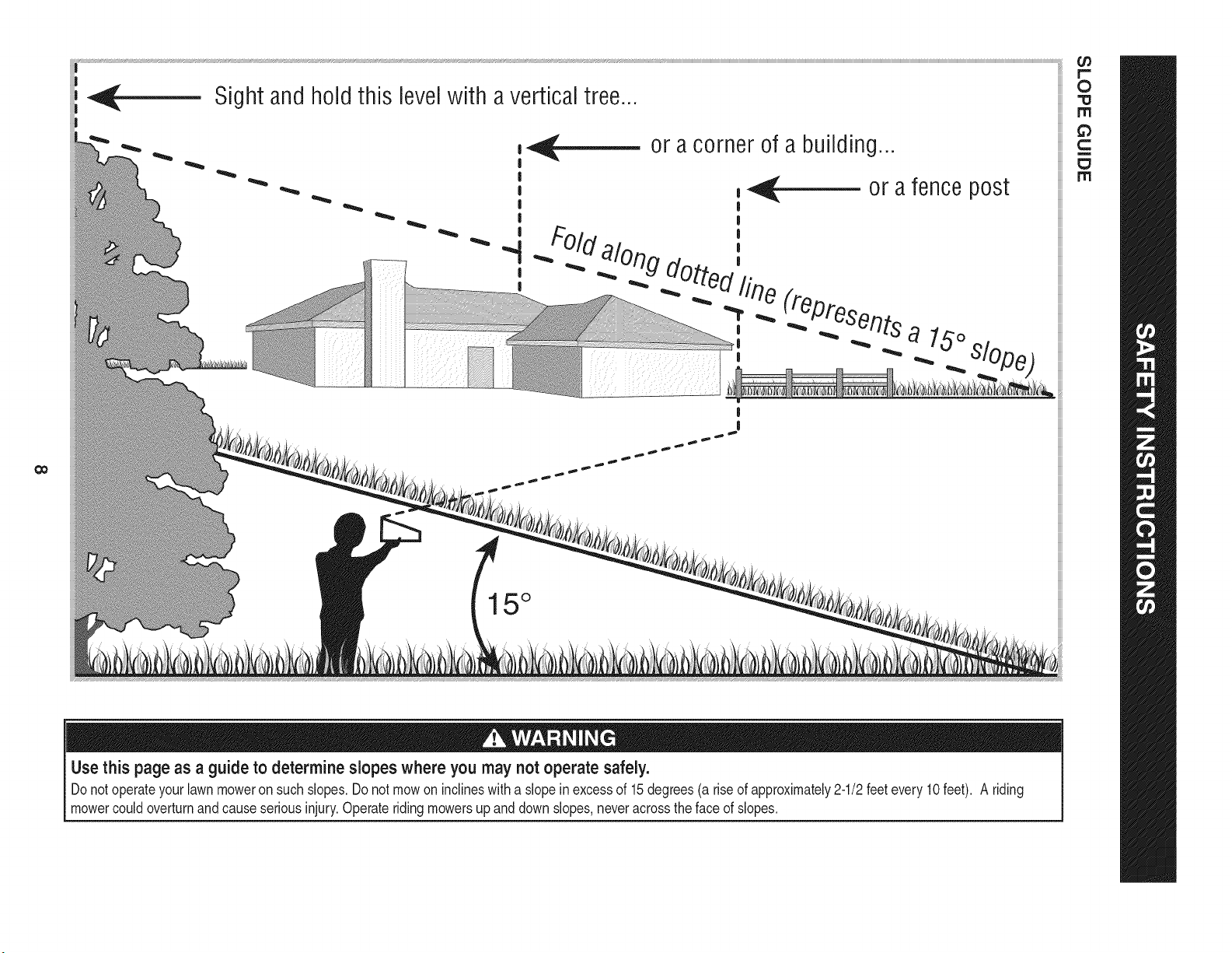
Sight and hold this
i
levelwith a vertical tree...
|
I
|
|
I
|
|
|
or a corner of a building...
15 °
Use this page as a guide to determine slopes where you may not operate safely.
Donot operateyourlawnmoweron suchslopes.Do notmow on inclineswith a slope inexcessof 15degrees(a rise of approximately2-1/2feet every 10feet). A riding
mowercouldoverturnand causeseriousinjury.Operateriding mowersup and downslopes,neveracrossthe faceof slopes.
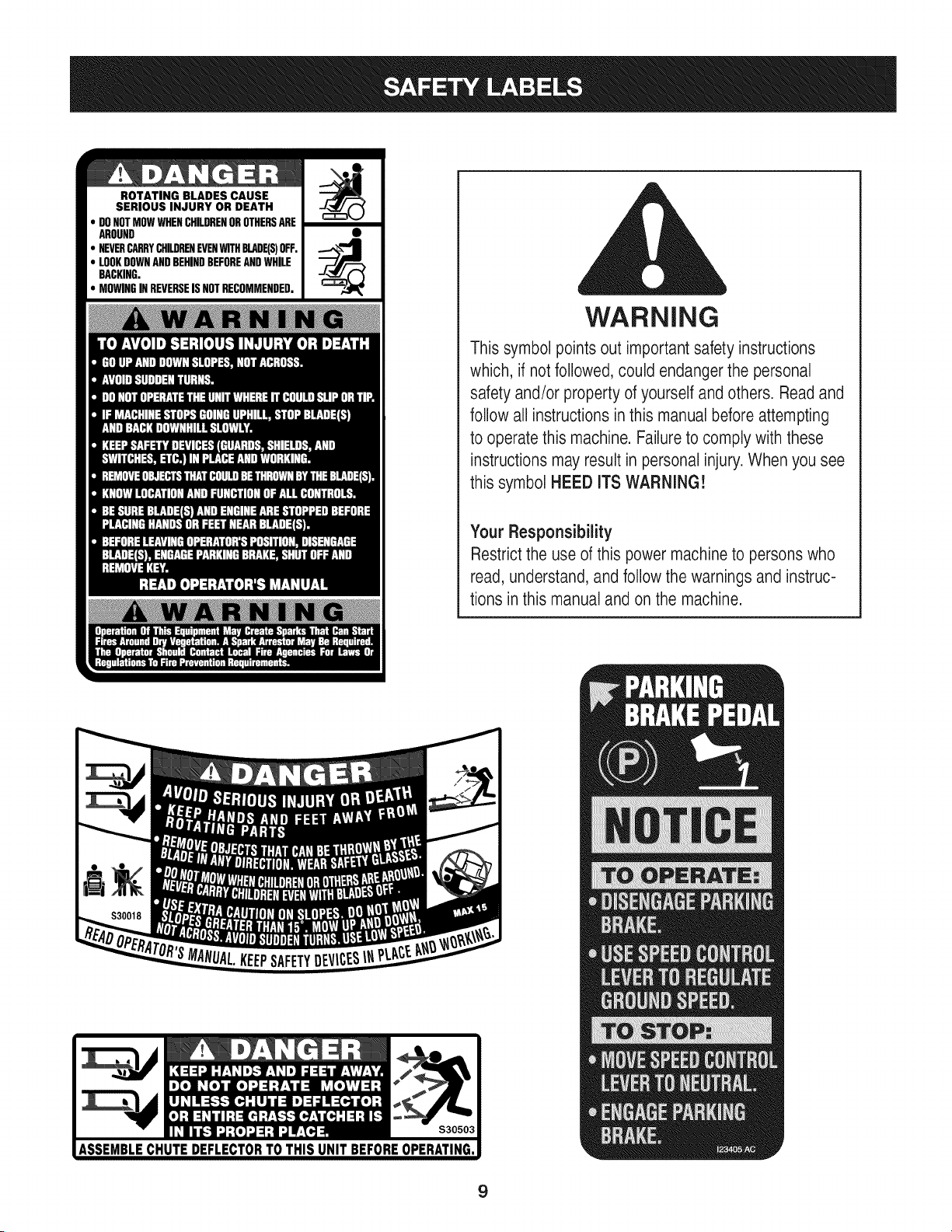
ROTATING BLADES CAUSE
SERIOUS INJURY OR DEATH
DONOTMOWWHENCHILDRENOROTHERSARE
AROUND
NEVERCARRYCHILDRENEVENWITHBLADE(S)OFF.
LOOKDOWNANDBEHINDBEFOREANDWHILE
BACKING.
MOWINGINREVERSEISNOTRECOMMENDED.
WARNING
This symbol points out important safety instructions
which, if notfollowed, could endangerthe personal
safety and/or property of yourself and others. Read and
follow all instructions inthis manual before attempting
to operatethis machine. Failure to comply with these
instructions may result in personal injury.When you see
this symbol HEED ITS WARNING!
Your Responsibility
Restrictthe use of this power machineto persons who
read, understand, and follow the warnings and instruc-
tions in this manual and on the machine.
9
IMPORTANT:Yourtractoris shippedwithmotoroil in theengine.
However,you MUSTcheckthe oil levelbeforeoperating.Referto the
Service& Maintenancesectionfor instructionson checkingtheoil
level.
Attaching the Battery Cables
CALIFORNIA PROPOSITION 65
Batteryposts,terminals,andrelatedaccessoriescontainleadand
leadcompounds,chemicalsknownto the Stateof Californiato
causecancerand reproductiveharm.Washhandsafter handling.
Whenattachingbatterycables,alwaysconnectthe POSITIVE(Red)
wireto its terminalfirst,followedby the NEGATIVE(Black)wire.
Forshippingreasons,bothbatterycables on yourequipmentmay
havebeen left disconnectedfrom the terminalsat the factory.To
connectthe batterycables,proceedasfollows:
NOTE:Thepositivebatteryterminalis markedPos.(+).The negative
batteryterminalis markedNeg. (-).
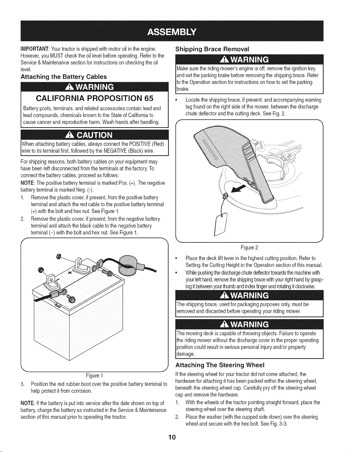
1. Removethe plasticcover,if present,fromthe positivebattery
terminaland attachthe redcableto the positivebatteryterminal
(+)withthe bolt andhexnut.See Figure1.
2. Removethe plasticcover,if present,fromthe negativebattery
terminaland attachthe black cableto the negativebattery
terminal(-) withthe bolt andhex nut.SeeFigure1.
f
J
Figure1
3. Positionthe red rubber boot over the positivebatteryterminalto
helpprotectit from corrosion.
NOTE:If thebatteryis put into serviceafter the dateshownon topof
battery,chargethe batteryas instructedinthe Service & Maintenance
sectionof this manualprior to operatingthe tractor.
Shipping Brace Removal
Makesurethe ridingmower'sengineis off, removetheignitionkey,
andset the parkingbrakebeforeremovingthe shippingbrace. Refer
Itothe Operationsectionfor instructionson howto setthe parking
lbrake.
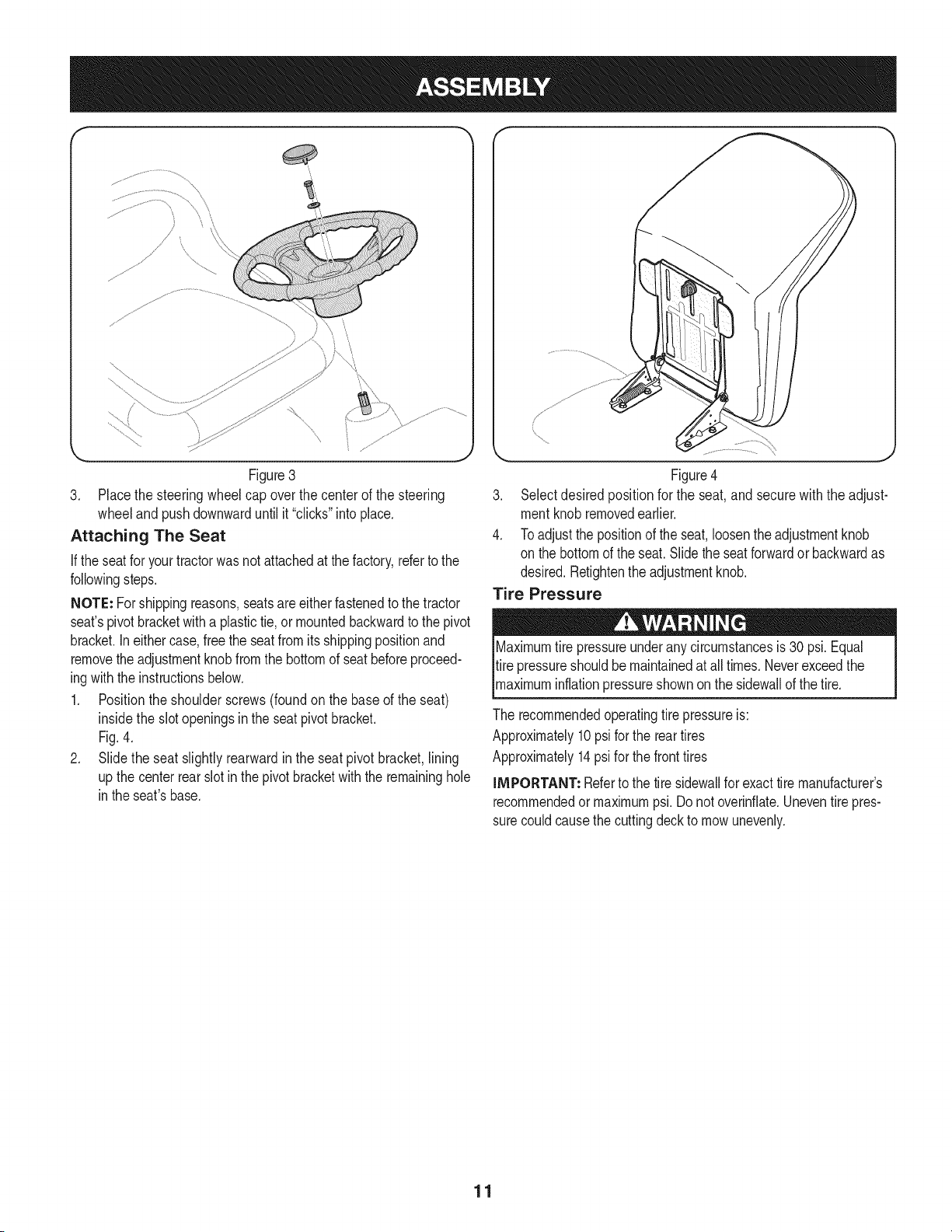
• Locatethe shippingbrace, if present,andaccompanyingwarning
tag foundonthe rightsideof the mower,betweenthe discharge
chutedeflectorand the cuttingdeck. See Fig. 2.
//
Figure2
Placethe deck lift leverinthe highestcuttingposition.Referto
SettingtheCuttingHeightin the Operationsectionof thismanual.
Whilepushingthedischargechuteddlectortowardsthemachinewith
yourlefthand,removetheshippingbracewithyourrighthandbygrasp-
ingitbetweenyourthumbandindexfingerandrotatingitclockwise.
The shippingbrace,usedfor packagingpurposesonly,mustbe
removedand discardedbeforeoperatingyour ridingmower.
The mowingdeck iscapableof throwingobjects. Failureto operate
the ridingmowerwithoutthe dischargecoverin the properoperating
Ipositioncould resultin seriouspersonalinjuryand/orproperty
ldamage.
Attaching The Steering Wheel
Ifthe steeringwheelfor yourtractordid notcomeattached,the
hardwarefor attachingit has beenpackedwithinthe steeringwheel,
beneaththe steeringwheelcap. Carefullypry off the steeringwheel
cap and removethe hardware.
1. Withthe wheelsof the tractorpointingstraightforward,placethe
steeringwheeloverthe steeringshaft.
2. Placethe washer(withthe cuppedsidedown)overthe steering
wheeland securewith the hex bolt. See Fig.3-3.
10
f
\
Figure3
3. Placethe steeringwheelcap overthe centerof the steering
wheeland pushdownwarduntilit "clicks"intoplace.
Attaching The Seat
If the seatfor yourtractorwasnotattachedat thefactory,refertothe
followingsteps.
NOTE: Forshippingreasons,seatsare eitherfastenedto the tractor
seat'spivotbracketwitha plastictie, or mountedbackwardto the pivot
bracket.Ineithercase,free the seatfromits shippingpositionand
removethe adjustmentknobfromthe bottomof seatbeforeproceed-
ingwiththe instructionsbelow.
1. Positionthe shoulderscrews(foundon the baseof the seat)
insidethe slot openingsin the seatpivot bracket.
Fig.4.
2. Slide the seat slightlyrearwardin the seatpivot bracket,lining
up the centerrear slot in thepivotbracketwith the remaininghole
in theseat'sbase.
Figure4
3. Selectdesired positionfor the seat,and secure with the adjust-
mentknobremovedearlier.
4. Toadjustthe positionof the seat,loosenthe adjustmentknob
on the bottomof the seat.Slidethe seatforwardor backwardas
desired.Retightenthe adjustmentknob.
Tire Pressure
X
Maximumtire pressureunderany circumstancesis 30 psi. Equal
tire pressureshouldbe maintainedat all times.Neverexceedthe
_maxmum nfat onpressureshownonthe s dewa of thet re.
The recommendedoperatingtire pressureis:
Approximately10psi forthe reartires
Approximately14psifor the front tires
IMPORTANT: Referto the tire sidewallfor exacttire manufacturer's
recommendedor maximumpsi. Donot overinfiate.Uneventirepres-
surecouldcausethe cuttingdeckto mowunevenly.
11
B
14
A
C
G
D
F
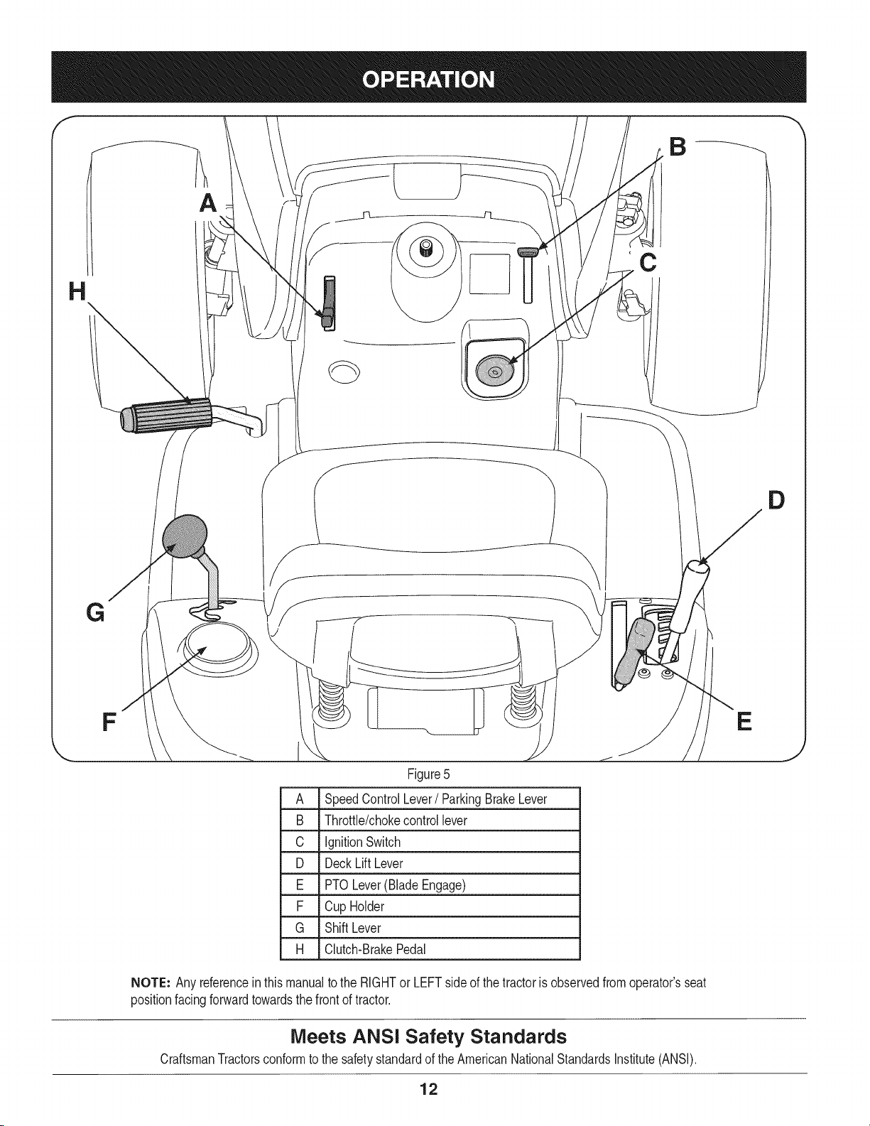
Figure5
A SpeedControl Lever/ ParkingBrakeLever
B Throttle/chokecontrol lever
C IgnitionSwitch
D Deck LiftLever
E PTO Lever(BladeEngage)
F Cup Holder
G ShiftLever
H Clutch-BrakePedal
NOTE: Any referencein thismanualto the RIGHTor LEFTsideof the tractoris observedfromoperator'sseat
positionfacingforwardtowardsthe frontof tractor.
Meets ANSi Safety Standards
CraftsmanTractorsconformto the safetystandardof theAmericanNationalStandardsInstitute(ANSI).
E
J
12
SPEED CONTROL LEVER
Thespeedcontrollever,locatedon the left sideof the
tractor'sdashconsole,allowsyouto regulatethe ground
speedof the lawntractor.Touse,depressthe clutch-
brakepedaland movethe leverout of the parkingbrake
notchandforwardto increasethetractor'sgroundspeed.
Whena desiredspeedhasbeenreached,releasethe
leverintoanappropriatenotchto maintainthat speed.
Toslow thetractor'sgroundspeed,depressthe clutch-
brakepedaland movethe speedcontrollever rearward
andreleaseit intoa notch.
PARKING BRAKE
Toset the parkingbrake,fully depressthe clutch-brake _._J
PARK
pedal.Movethe speedcontrol leverall the waydownand BRAKE
intothe parkingbrakeposition.Releasethe clutch-brake
pedalto allowthe parkingbraketo engage.
Toreleasethe parkingbrake,depressthe clutch-brakepedaland
movethe speedcontrolleveroutof the notchestothe desiredposition.
Releasethe speedcontrolleverandthe clutch-brakepedal.
NOTE: The parkingbrakemustbe setif the operatorleavesthe seat
withthe enginerunningor the enginewill automaticallyshutoff.
THROTTLE/CHOKE CONTROL LEVER
Thethrottle/chokecontrolleveris locatedon the rightsideof thetrac-
tor'sdash panel.This levercontrolsthe speedof the engineandwhen
pushedall theway forward,the chokecontrolalso.Whensetin a given
position,the throttlewillmaintaina uniformenginespeed.
iMPORTANT: Whenoperatingthe tractorwiththe cuttingdeck
engaged,thethrottle/chokecontrollevermustalwaysbein the FAST
(rabbit)position.
IGNITION SWITCH
Thekey switch moduleis usedto
startand stopthe engine.Insert
keyintothe keyswitchmodule
andturnclockwiseto theSTART
position.Releasethe keyinto the
normalmowingpositiononceen-
ginehasstarted.The headlights
will be activatedautomatically.
Tostop the engine,turnthe
ignitionkeycounterclockwiseto
the STOPposition.
IMPORTANT:Prior to operatingthe tractor,referto boththe "Safety
InterlockSystem"and"StartingThe Engine"laterinthissectionof this
manualfor detailedinstructionsregardingthe IgnitionSwitchModule.
Neverleavea runningmachineunattended.AlwaysdisengagePTO
(BladeEngageLever),moveshiftleverintoneutralposition,setpark-
ingbrake,stopengineandremovekeyto preventunintendedstarting.
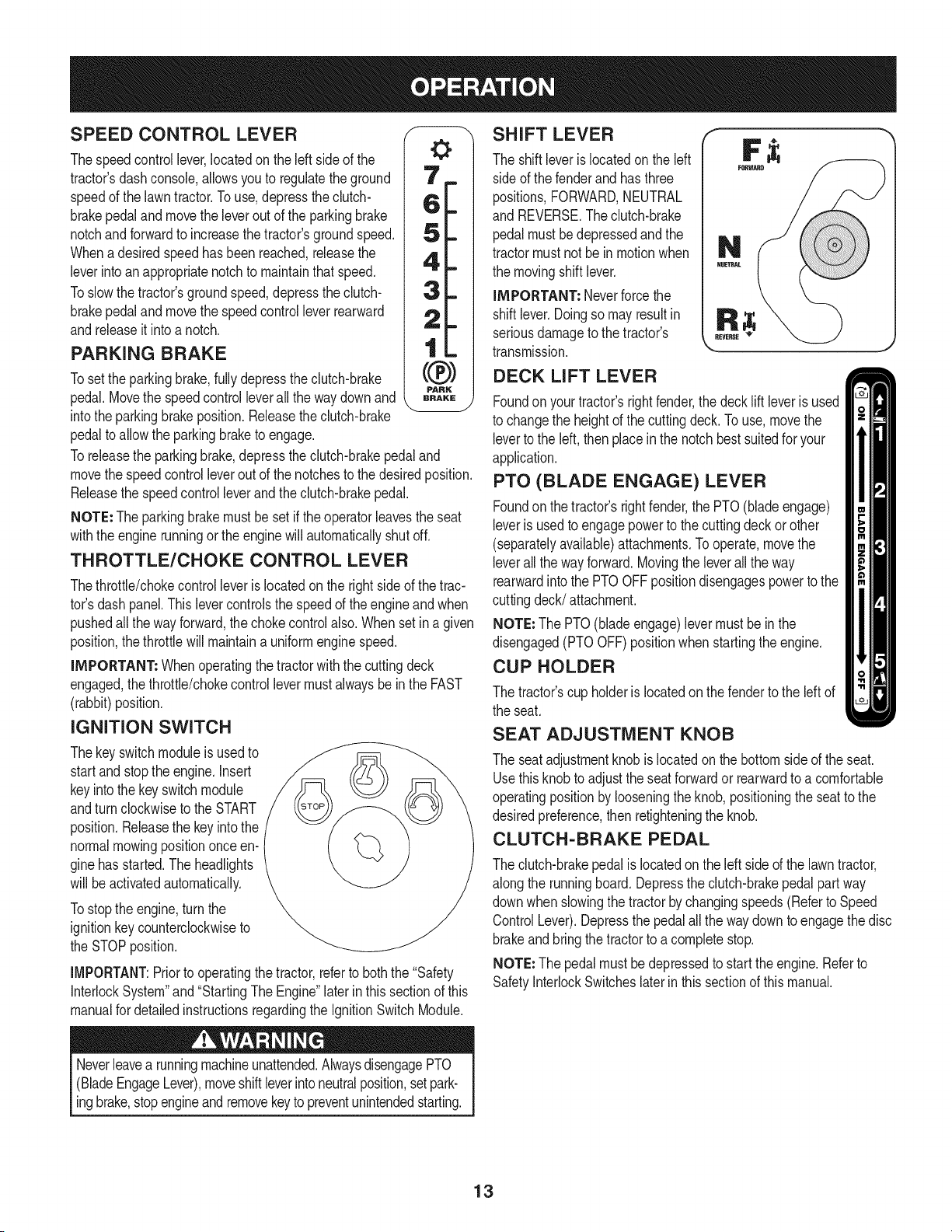
SHIFT LEVER
The shift leveris locatedonthe left
sideof the fenderand hasthree
positions,FORWARD,NEUTRAL
and REVERSE.Theclutch-brake
pedalmustbe depressedand the
tractormustnot be inmotionwhen
the movingshift lever.
iMPORTANT: Neverforce the
shiftlever.Doingso may resultin
seriousdamageto the tractor's
transmission.
DECK LIFT LEVER
Foundonyour tractor'srightfender,the deckliftleveris used
to changethe heightof the cuttingdeck.To use, movethe
leverto the left, thenplacein the notchbestsuitedfor your
application.
PTO (BLADE ENGAGE) LEVER
Foundonthe tractor'srightfender,the PTO(bladeengage)
leveris usedto engagepowerto the cuttingdeck or other
(separatelyavailable)attachments.Tooperate,movethe
leverall theway forward.Movingthe leverall the way
rearwardinto the PTOOFFpositiondisengagespowerto the
cuttingdeck/attachment.
NOTE: The PTO(bladeengage)levermustbe inthe
disengaged(PTOOFF)positionwhenstartingthe engine.
CUP HOLDER
The tractor'scup holderis locatedon the fenderto the left of
the seat.
SEAT ADJUSTMENT KNOB
The seat adjustmentknob is locatedon the bottomsideof the seat.
Usethisknob to adjustthe seatforwardor rearwardto a comfortable
operatingpositionby looseningthe knob,positioningthe seatto the
desiredpreference,thenretighteningthe knob.
CLUTCH-BRAKE PEDAL
The clutch-brakepedal is locatedonthe left sideof the lawntractor,
alongthe runningboard.Depressthe clutch-brakepedalpart way
downwhenslowingthe tractorbychangingspeeds(Referto Speed
ControlLever).Depressthe pedalall the waydownto engagethe disc
brakeandbring the tractorto a completestop.
NOTE: The pedalmustbe depressedto startthe engine.Referto
SafetyInterlockSwitcheslaterin this sectionof this manual.
13
Gas and Oil Fill=up
0il
iMPORTANT: Yourtractoris shippedwithmotoroil inthe engine.
However,you MUSTcheckthe oil levelbeforeoperating.Be careful
notto overfill.
Forinstructionson howto checkthe engineoil, referto CheckingThe
EngineOilin the ServiceandMaintenancesectionof this manual.
Alwayschecktheengineoil levelbeforeeachuseas instructedin
the Maintenancesection.Addoil as necessary.Failureto do so may
resultin seriousdamageto yourengine.
Gasoline
Thegasolinetank is locatedunderthe hood.Do notoverfill.
Useextremecarewhenhandlinggasoline.Gasolineis extremely
flammableandthe vaporsare explosive.Neverfuel machineindoors
orwhilethe engineis hotor running.Extinguishcigarettes,cigars,
_ppes,andothersourcesof gn t on.
NOTE : Purchasegasolinein small quantities.Do notuse gasolineleft
overfromthe previousseason,to minimizegumdepositsin the fuel
system.
• Thisengineis certifiedto operateon unleadedgasoline.For best
results,fill the fueltank with onlyclean,fresh,unleadedgasoline
witha pumpstickeroctaneratingof 87or higher.
• Gasohol(upto 10%ethylalcohol,90%unleadedgasolineby
volume)is an approvedfuel. Othergasoline/alcoholblends,such
as E85,arenot approved.
• MethylTertiaryButylEther(MTBE)andunleadedgasolineblends
(upto a maximumof 15%MTBEby volume)are approvedfuels.
Othergasoline/etherblendsare notapproved.
• Fillfuel tankoutdoorsorin well-ventilatedarea.
• Do notoverfillfuel tank. Filltankto no morethan 1/2inch below
bottomof filler neckto allowspacefor fuel expansion.
• Neverremovegas capor addfuel whilethe engineis hot or run-
ning.Allowengineto cool at leasttwo minutesbeforerefueling.
• Ifgasolineis spilled,wipe it off theengineandequipment.Move
machineto anotherarea.Wait5 minutesbeforestartingthe
engine.
To Add Gasoline
1. Turnthe engineoff andlet enginecool at least2 minutesbefore
removingthe fuelcap.The gasolinetankis locatedunderthe
hood.Removethe fuel cap byturningit counterclockwise.
2. Fillthefuel tankwithgasoline.Useonlyclean,fresh(nomorethan
30daysold),unleadedgasoline.Filltankto nomorethan 1/2inch
belowbottomof fillernecktoallowspaceforfuelexpansion.
3. Reinstallthe fuelcap.
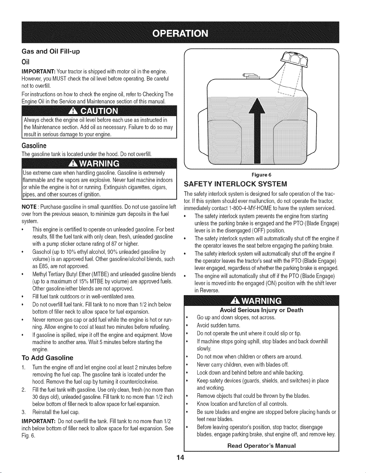
iMPORTANT: Donot overfillthe tank. Filltank to nomorethan 1/2
inchbelowbottomof filler neckto allowspacefor fuel expansion.See
Fig.6.
Figure 6
SAFETY INTERLOCK SYSTEM
J
The safetyinterlocksystemis designedfor safeoperationof the trac-
tor.If thissystemshouldevermalfunction,do not operatethe tractor,
immediatelycontact1-800-4-MY-HOMEto havethe systemserviced.
• The safetyinterlocksystempreventsthe enginefrom starting
unlessthe parkingbrakeis engagedandthe PTO(Blade Engage)
leveris in the disengaged(OFF)position.
• The safetyinterlocksystemwill automaticallyshut off the engineif
the operatorleavesthe seatbeforeengagingthe parkingbrake.
• The safetyinterlocksystemwillautomaticallyshutoff theengineif
the operatorleavesthetractor'sseatwiththePTO(BladeEngage)
leverengaged,regardlessof whetherthe parkingbrakeisengaged.
• The enginewill automaticallyshut off if the PTO(BladeEngage)
leveris movedinto theengaged(ON) positionwiththe shiftlever
in Reverse.
Avoid Serious injury or Death
• Goup anddownslopes,not across.
• Avoidsuddenturns.
• Do notoperatethe unitwhereitcouldslip ortip.
• If machinestopsgoinguphill,stop bladesand back downhill
slowly.
• Do not mowwhenchildrenor othersarearound.
• Nevercarrychildren,evenwithbladesoff.
• Lookdownandbehindbeforeandwhilebacking.
• Keepsafetydevices(guards,shields,andswitches)in place
andworking.
• Removeobjectsthatcould be thrownby the blades.
• Knowlocationandfunctionof all controls.
• Be surebladesandengineare stoppedbeforeplacinghandsor
feetnear blades.
• Beforeleavingoperator'sposition,stoptractor,disengage
blades,engageparkingbrake,shut engineoff, andremovekey.
Read Operator's Manual
14
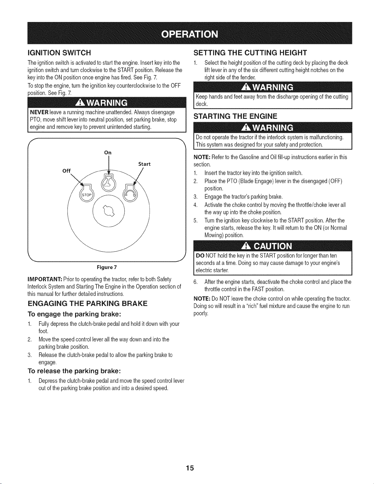
iGNiTiON SWITCH
Theignitionswitchis activatedto startthe engine.Insertkeyintothe
ignitionswitchand turnclockwiseto the STARTposition.Releasethe
keyintothe ON positiononce enginehas fired.SeeFig.7.
Tostop the engine,turnthe ignitionkeycounterclockwiseto the OFF
position.SeeFig. 7.
NEVERleavea runningmachineunattended.Alwaysdisengage
PTO,moveshift leverintoneutralposition,set parkingbrake,stop
engne and removekeyto preventunntendedstartng.
F
On
Start
off
Figure 7
iMPORTANT: Priorto operatingthe tractor,referto both Safety
InterlockSystemandStartingThe Engineinthe Operationsectionof
thismanualfor furtherdetailedinstructions.
ENGAGING THE PARKING BRAKE
To engage the parking brake:
1. Fullydepressthe clutch-brakepedal and hold itdownwithyour
foot.
2. Movethe speedcontrolleverallthe waydownand intothe
parkingbrakeposition.
3. Releasethe dutch-brakepedalto allowthe parkingbraketo
engage.
To release the parking brake:
1. Depressthe clutch-brakepedal and movethe speedcontrollever
out of the parkingbrakepositionand intoa desiredspeed.
SETTING THE CUTTING HEIGHT
1. Selectthe heightpositionof the cuttingdeckby placingthe deck
liftleverin anyof the sixdifferentcutting heightnotchesonthe
rightsideof the fender.
Keephandsand feet away fromthe dischargeopeningof the cutting
deck.
STARTING THE ENGINE
Donot operatethe tractorif the interlocksystemismalfunctioning.
Thissystemwasdesignedfor yoursafetyand protection.
NOTE: Referto the Gasolineand Oil fill-up instructionsearlierin this
section.
1. Insertthe tractorkey intothe ignitionswitch.
2. Placethe PTO(BladeEngage)leverin thedisengaged(OFF)
position.
3. Engagethe tractor'sparkingbrake.
4. Activatethechokecontrolby movingthethrottle/chokeleverall
the way up into thechoke position.
5. Turnthe ignitionkeyclockwiseto the STARTposition.Afterthe
enginestarts,releasethe key.Itwill returnto the ON(or Normal
Mowing)position.
DO NOTholdthe keyinthe STARTpositionfor longerthan ten
secondsat a time. Doingso maycausedamageto your engine's
electricstarter.
6. After the enginestarts,deactivatethe chokecontrolandplacethe
throttlecontrolin the FASTposition.
NOTE: Do NOTleavethe chokecontrolon whileoperatingthe tractor.
Doingso will resultina "rich"fuel mixtureand cause theengineto run
poorly.
15
STOPPING THE ENGINE
If youstrikea foreignobject,stopthe engine,disconnectthe spark
plugwire(s)andgroundagainstthe engine.Thoroughlyinspectthe
machinefor anydamage.Repairthe damagebeforerestartingand
operating
1. If the bladesare engaged,placethe PTO(Blade Engage)leverin
thedisengaged(OFF) position.
2. Turnthe ignitionkey counterclockwiseto the STOPposition.
3. Removethe keyfrom the ignitionswitchto preventunintended
starting.
DRIVING THE TRACTOR
Avoidsuddenstarts,excessivespeedand suddenstops.
Do notleavethe seatof thetractorwithoutfirstplacingthe PTO
(BladeEngage)leverinthe disengaged(OFF)position,depressing
I the brakepedaland engagingthe parkingbrake.If leavingthe tractor
[ unattended,alsoturn the ignitionkey offand removethe key.
Alwayslookdownandbehindbeforeandwhilebackingupto avoida
back-overaccident.
1. Depressthe clutch-brakepedalto releasethe parkingbrakeand
thenlet the pedal up.
2. Movethe throttleleverintothe FAST(rabbit)position.
3. Placethe shiftleverineitherthe FORWARDor REVERSE
position.
IMPORTANT: Do NOTusethe shift leverto changethe directionof
travelwhenthe tractorisin motion.Alwaysusethe clutch-brakepedal
to bring thetractorto a completestop beforeshifting.
4. Releasethe parkingbrakeby depressingthe clutch-brakepedal
andpositioningthe speedcontrol leverinthe desiredposition.
IMPORTANT: First-timeoperatorsshouldusespeedpositions1or
2. Becomecompletelyfamiliarwith the tractor'soperationandcontrols
beforeoperatingthe tractorinhigherspeedpositions.
5. Releaseclutch-brakepedalslowlyto put unit intomotion.
6. The lawntractoris broughtto a stop bydepressingthe clutch-
brakepedal.
NOTE: Whenoperatingthe unit initially,therewill be little difference
betweenthe highesttwo speedsuntil afterthe beltshaveseated
themselvesintothe pulleysduringthe break-inperiod.
WARNING!Beforeleavingthe operator'spositionfor any reason,
disengagethe blades,placethe shift leverinneutral,engagethe
parkingbrake,shutengineoff and removethe key.
1. Placethe shift leverinneutral,
2. Engagethe parkingbrake,
3. Shutengineoff and removethe key.Doingso will minimizethe
possibilityof havingyour lawn"browned" byhot exhaustfrom
yourtractor'srunningengine.
Ifunit stallswithspeedcontrolinhigh speed,or if unitwill not operate
withspeedcontrol leverin a lowspeedposition,proceedas follows:
1. Placeshift leverin NEUTRAL.
2. Restartengine.
3. Placespeedcontrolleverinhighestspeedposition.
4. Releaseclutch-brakepedalfully.
5. Depressclutch-brakepedal.
6. Placespeedcontrolleverindesiredposition.
7. Placeshift leverineither FORWARDor REVERSE,andfollow
normaloperatingprocedures.
DRIVING ON SLOPES
Referto the SLOPEGAUGEinthe SafetyInstructionssectionof the
manualto helpdetermineslopeswhereyoumay operatethis tractor
safely.
Donot mowon inclineswith a slopeinexcessof 15degrees(a rise
of approximately2-1/2feetevery10 feet).The tractorcouldoverturn
andcause seriousinjury.
• Mowupanddown slopes,NEVERacross.
• Exerciseextremecautionwhenchangingdirectionon slopes.
• Watchfor holes,ruts,bumps,rocks,orother hiddenobjects.
Uneventerraincouldoverturnthe machine.Tallgrasscan hide
obstacles.
• Avoidturnswhendrivingon a slope.If a turnmustbe made,turn
downthe slope.Turningupa slopegreatlyincreasesthe chance
of a rollover.
• Avoidstoppingwhendrivingup a slope.If itis necessaryto stop
whiledrivingupa slope,start upsmoothlyandcarefullyto reduce
the possibilityof flippingthe tractoroverbackward.
ENGAGING THE BLADES
Engagingthe PTO(BladeEngage)transferspowerto the cuttingdeck
or other(separatelyavailable)attachments.To engagethe blades,
proceedasfollows:
1. Movethethrottle/chokecontrolleverto the FAST(rabbit)position.
2. Graspthe PTO(BladeEngage)leverandpivotit all theway
forwardinto theengaged(ON) position.
3. Keepthethrottleleverin the FAST(rabbit)positionfor the most
efficientuseof the cuttingdeck or other(separatelyavailable)
attachments.
NOTE: The enginewillautomaticallyshutoff if the PTO(Blade
Engage)leveris movedintothe engaged(ON)positionwith the shift
leverin Reverse.
IMPORTANT: Whenstoppingthe tractorfor any reasonwhileon a
grasssurface,always:
16
MULCHING
A mulch kit is available as an attachment. Mulching is a process of
recirculating grass clippings repeatedly beneath the cutting deck.
The ultra-fine clippings are then forced back into the lawn where
they act as a natural fertilizer.
A mulchkit canbe purchased.See the ReplacementParts& Attach-
mentssectionof this manualfor moreinformation.
USING THE DECK LIFT LEVER
Toraisethe cuttingdeck,movethe deck lift levertothe left,then place
it in the notchbestsuitedfor yourapplication.Referto SettingThe
CuttingHeightearlierin this Operationsection.
MOWING
Tohelp avoidbladecontactor a thrownobject injury,keepbystand-
ers,helpers,childrenand pets at least75 feet fromthe machine
whileit is inoperation.Stop machineif anyoneentersthearea.
Thefollowinginformationwill behelpfulwhenusingthe cuttingdeck
withyourtractor:
Planyour mowingpatternto avoiddischargeof materialstoward
roads,sidewalks,bystandersandthe like.Also, avoiddischarging
materialagainsta wallor obstructionwhich maycausedischarged
materialto ricochetbacktowardthe operator.
HEADLIGHTS
• The lampsare ONwheneverthe tractor'sengineis running.
• The lampsturn OFFwhenthe ignitionkey is movedto the STOP
position.
• Do not mowat high groundspeed,especiallyif a mulchkit or
grasscollectoris installed.
• For best resultsit is recommendedthat the firsttwo laps becut
withthe dischargethrowntowardsthe center.Afterthe first two
laps,reversethe directionto throwthe dischargeto the outside
for the balanceof cutting.Thiswill givea betterappearanceto the
lawn.
• Do notcut thegrass too short.Shortgrassinvitesweedgrowth
andyellowsquicklyin dry weather.
• Mowingshouldalwaysbe done withthe engineat full throttle.
• Underheavierconditionsit maybenecessaryto go back overthe
cutareaa secondtime to geta cleancut.
• Do NOTattemptto mowheavybrushand weedsand extremely
tall grass.Yourtractoris designedto mowlawns,NOTclear
brush.
• Keepthe bladessharpandreplacethe bladeswhenworn.Refer
to CuttingBladesin the Servicesectionof this manualfor proper
bladesharpeninginstructions.
17
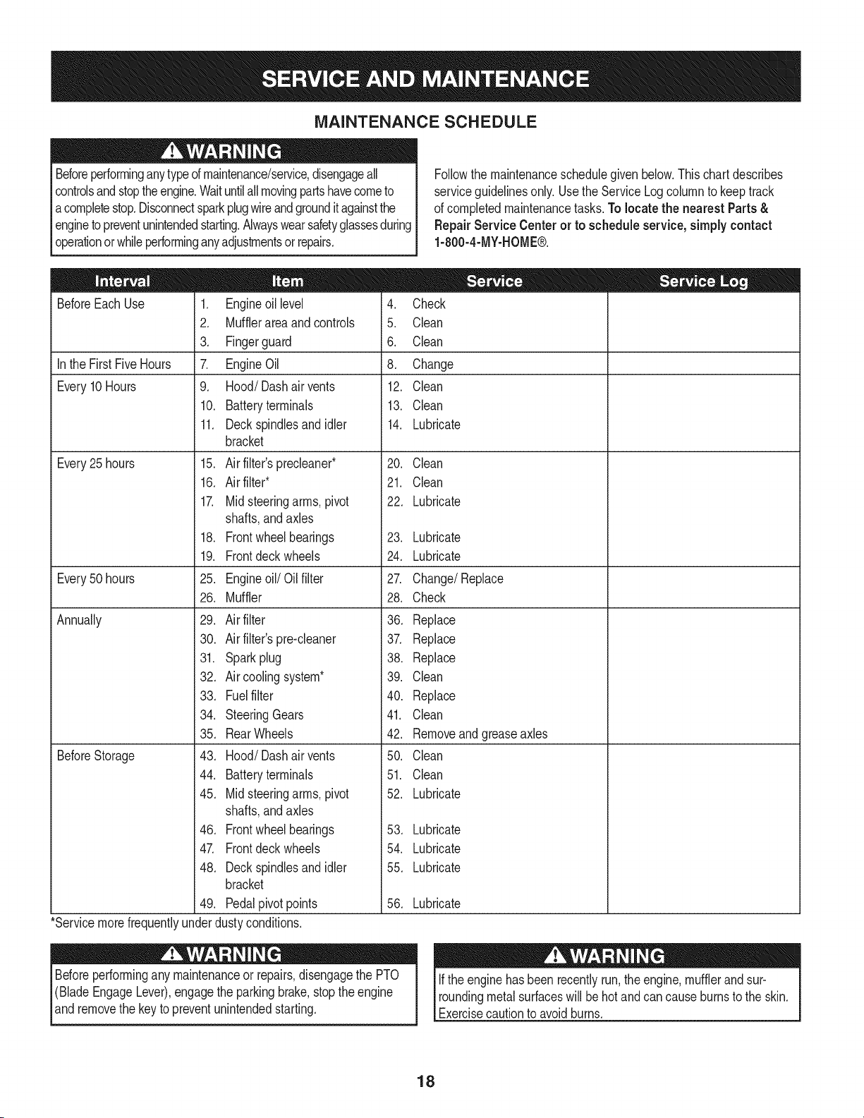
MAINTENANCE SCHEDULE
Beforeperforminganytypeof maintenance/service,disengageall
controlsand stoptheengine.Waituntilall movingpartshavecometo
acompletestop.Disconnectsparkplugwireandgrounditagainstthe
enginetopreventunintendedstarting.Alwayswearsafetyglassesduring
operationor whileperforminganyadjustmentsor repairs.
Followthe maintenanceschedulegivenbelow.Thischart describes
serviceguidelinesonly. Usethe ServiceLogcolumnto keeptrack
of completedmaintenancetasks.To locate the nearest Parts&
Repair Service Centeror to scheduleservice,simplycontact
1-800-4-MY-HOME®.
BeforeEachUse
In the FirstFive Hours
Every10Hours
Every25 hours
Every50 hours
Annually
BeforeStorage
1. Engineoil level
2. Mufflerareaandcontrols
3. Fingerguard
7. EngineOil
9. Hood/Dashairvents
10. Batteryterminals
11. Deckspindlesand idler
bracket
15. Air filter'sprecleaner*
16. Air filter*
17. Midsteeringarms,pivot
shafts,andaxles
18. Frontwheelbearings
19. Frontdeck wheels
25. Engineoil/Oil filter
26. Muffler
29. Air filter
30. Air filter'spre-cleaner
31. Sparkplug
32. Air coolingsystem*
33. Fuelfilter
34. SteeringGears
35. RearWheels
43. Hood/Dash air vents
44. Batteryterminals
45. Midsteeringarms,pivot
shafts,andaxles
46. Frontwheelbearings
47. Frontdeck wheels
48. Deckspindlesand idler
bracket
49. Pedalpivot points
4. Check
5. Clean
6. Clean
8. Change
12. Clean
13. Clean
14. Lubricate
20. Clean
21. Clean
22. Lubricate
23. Lubricate
24. Lubricate
27. Change/Replace
28. Check
36. Replace
37. Replace
38. Replace
39. Clean
40. Replace
41. Clean
42. Removeand greaseaxles
50. Clean
51. Clean
52. Lubricate
53. Lubricate
54. Lubricate
55. Lubricate
56. Lubricate
*Servicemorefrequentlyunderdustyconditions.
Beforeperformingany maintenanceor repairs,disengagethe PTO
(BladeEngageLever),engagethe parkingbrake,stopthe engine
and removethe key to preventunintendedstarting.
Ifthe enginehasbeen recentlyrun,the engine,mufflerandsur-
roundingmetalsurfaceswill be hotand cancauseburnsto the skin.
Exercisecautionto avoidburns.
18
ENGINE MAINTENANCE
Checking the Engine Oil
Onlyuse highqualitydetergentoil ratedwith APIserviceclassification
SF,SG,SH, or SJ, Selectthe oil's SAEviscositygradeaccordingto
the expectedoperatingtemperature.Followthe chartbelow.
Althoughmulti-viscosityoils (5W20,10W30,etc.)improvestarting
in coldweather,they will resultinincreasedoil consumptionwhen
usedabove32°E Checkyour engineoillevelmorefrequentlyto avoid
possibleenginedamagefrom runninglowonoil.
('_older _ 32°F _War me'_r
Oil Viscosity Chart
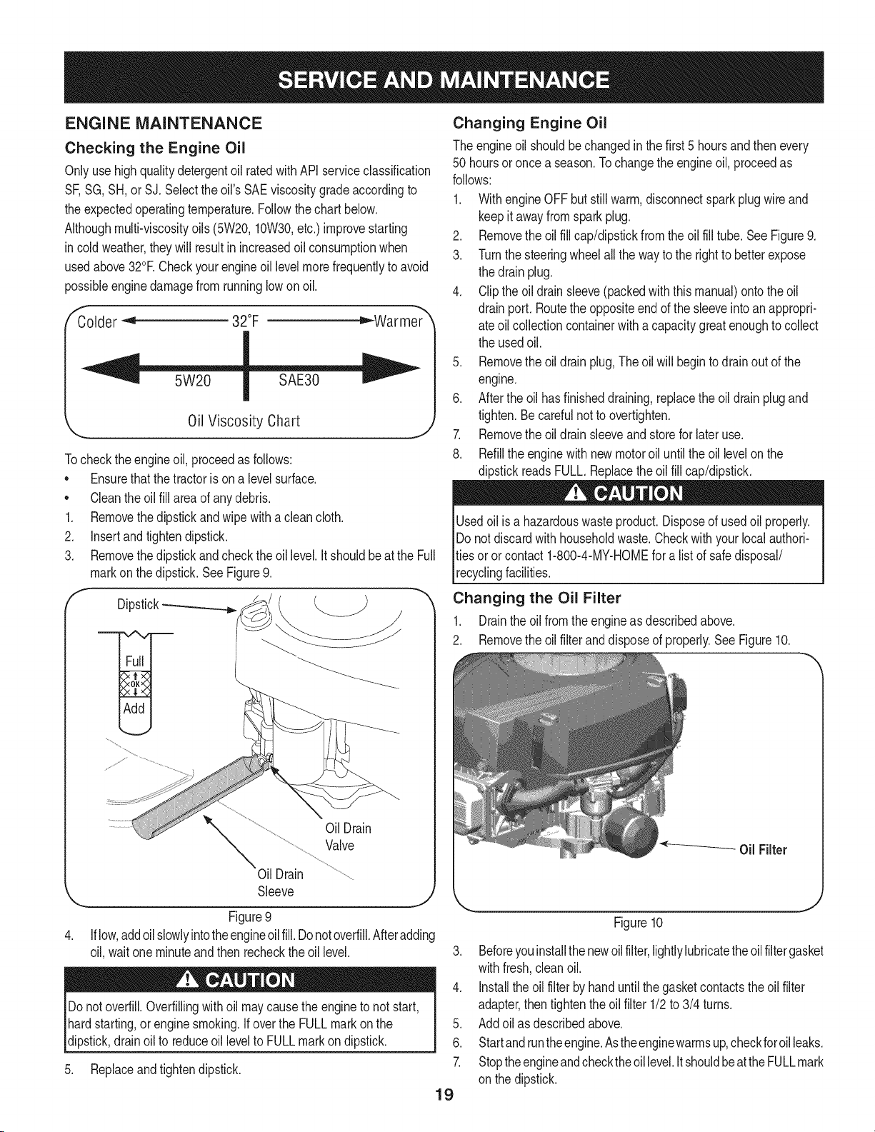
Tocheckthe engineoil, proceedas follows:
• Ensurethatthe tractoris on a levelsurface.
• Cleantheoil fill area of anydebris.
1. Removethedipstickand wipe witha clean cloth.
2. Insertandtightendipstick.
3. Removethe dipstickandchecktheoil level.It shouldbe atthe Full
markon thedipstick.SeeFigure9.
f
Dipstick-_
OilDrain
Valve
Oil Drain
Sleeve
J
Figure9
Iflow,addoilslowlyintotheengineoilfill. Donotoverfill.Afteradding
oil, waitone minuteand then recheckthe oil level.
Donotoverfill.Overfillingwith oil maycausethe engineto not start,
hardstarting,or engine smoking.If overthe FULLmark on the
dipstick,drainoil to reduceoil levelto FULLmarkondipstick.
5. Replaceandtightendipstick.
Changing Engine Oil
The engineoil shouldbe changedinthe first 5 hoursand thenevery
50 hoursor once a season.Tochangethe engineoil, proceedas
follows:
1. WithengineOFFbut stillwarm,disconnectsparkplugwireand
keepit awayfromsparkplug.
2. Removethe oilfill cap/dipstickfromtheoil fill tube.SeeFigure9.
3. Turnthe steeringwheelallthe wayto the rightto betterexpose
the drain plug.
4. Clipthe oildrain sleeve(packedwith this manual)ontothe oil
drainport. Routethe oppositeend of the sleeveintoanappropri-
ate oil collectioncontainerwith a capacitygreatenoughto collect
the usedoil.
5. Removethe oildrain plug,The oilwill begintodrainout of the
engine.
6. After the oil hasfinisheddraining,replacethe oil drainplugand
tighten.Be carefulnot to overtighten.
7. Removethe oildrainsleeveandstorefor later use.
8. Refillthe enginewith newmotoroil untilthe oil levelon the
dipstickreadsFULL.Replacetheoil fill cap/dipstick.
Usedoil is a hazardouswasteproduct.Disposeof usedoil properly.
Do notdiscardwithhouseholdwaste.Checkwith your localauthori-
ties oror contact1-800-4-MY-HOMEfor alist of safedisposal/
recyclingfacilities.
Changing the Oil Filter
1. Drainthe oil fromthe engineas describedabove.
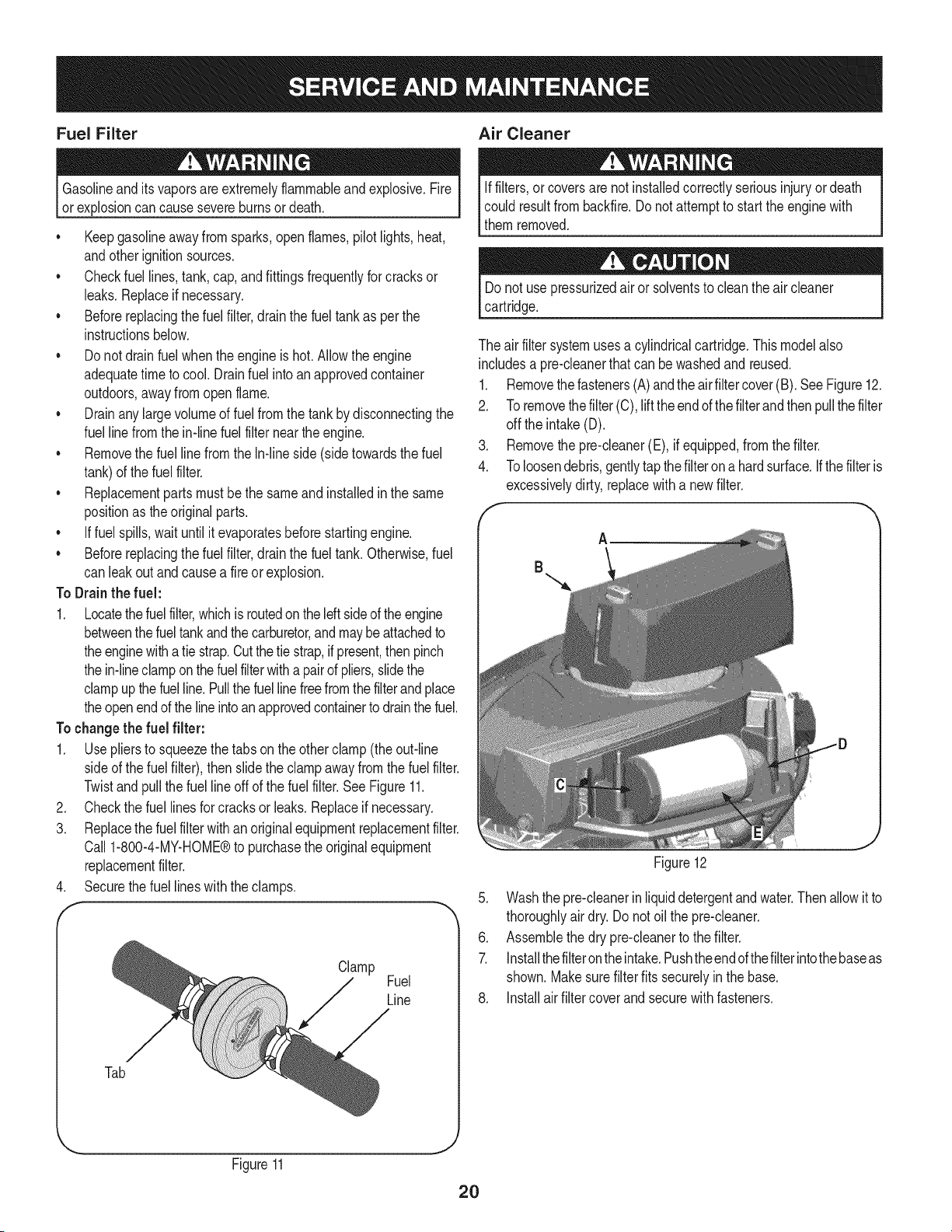
2. Removethe oilfilter and disposeof properly.See Figure10.
19
J
Figure10
3. Beforeyouinstallthe newoilfilter,lightlylubricatethe oilfilter gasket
withfresh,cleanoil.
4. Installthe oil filter byhanduntilthe gasketcontactstheoil filter
adapter,then tightenthe oilfilter 1/2to 3/4 turns.
5. Add oil as describedabove.
6. Startandruntheengine.Astheenginewarrnsup,checkforoilleaks.
7. Stoptheengineandchecktheoil level.It shouldbeatthe FULLmark
on the dipstick.
Fuel Filter Air Cleaner
Gasolineand itsvaporsareextremelyflammableandexplosive.Fire
orexplosioncan causesevereburnsor death.
• Keepgasolineawayfromsparks,openflames,pilotlights,heat,
andotherignitionsources.
• Checkfuel lines, tank,cap,and fittingsfrequentlyforcracksor
leaks.Replaceif necessary.
• Beforereplacingthe fuelfilter,drainthe fueltank as perthe
instructionsbelow.
• Do notdrainfuel whenthe engineishot.Allowthe engine
adequatetimeto cool. Drainfuel intoan approvedcontainer
outdoors,awayfromopenflame.
• Drainanylargevolumeof fuelfromthe tankby disconnectingthe
fuel linefrom the in-linefuelfilter near theengine.
• Removethe fuel line from the In-lineside (sidetowardsthe fuel
tank)of thefuel filter.
• Replacementpartsmustbethe sameand installedin the same
positionas theoriginalparts.
• Iffuel spills,waituntil itevaporatesbeforestartingengine.
• Beforereplacingthe fuelfilter,drainthe fueltank. Otherwisefuel
can leakout andcausea fireor explosion.
To Drainthe fuel:
1. Locatethefuelfilter,whichis routedonthe leftsideofthe engine
betweenthe fueltankandthe carburetor,and maybe attachedto
theenginewitha tie strap.Cutthetie strap,ifpresent,then pinch
thein-lineclampon thefuelfilterwitha pairof pliers,slidethe
clampupthefuelline.Pullthe fuellinefreefromthefilterand place
theopenend of the lineintoan approvedcontainerto drainthefuel.
Tochangethe fuel filter:
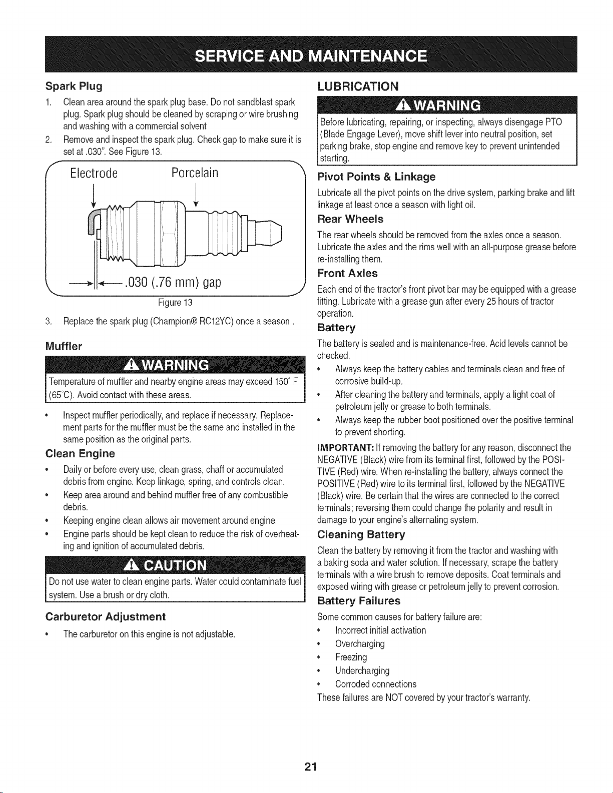
1. Usepliersto squeezethe tabsonthe otherclamp(theout-line
sideof the fuel filter),thenslidethe clampawayfromthe fuel filter.
Twistandpull the fuellineoff of the fuelfilter.SeeFigure11.
2. Checkthe fuel linesfor cracksor leaks.Replaceif necessary.
3. Replacethe fuelfilter with an originalequipmentreplacementfilter.
Call 1-800-4-MY-HOME®to purchasethe originalequipment
replacementfilter.
4. Securethe fuel lineswiththe clamps.
f
Clamp
Fuel
Line
Tab
Iffilters,or coversare notinstalledcorrectlyseriousinjuryordeath
could resultfrom backfire.Do notattemptto startthe enginewith
themremoved.
Donot use pressurizedair or solventsto cleanthe aircleaner
cartridge.
The air filter systemuses a cylindricalcartridge.Thismodelalso
includesa pre-cleanerthatcan be washedand reused.
1. Removethefasteners(A) andtheairfilter cover(B). SeeFigure12.
2. Toremovethefilter(C), lifttheendofthe filterandthen pullthefilter
off the intake(D).
3. Removethe pre-cleaner(E), if equipped,from the filter.
4. Toloosendebris,gentlytapthefilter on a hard surface,ifthe filteris
excessivelydirty,replacewith a newfilter.
f --,,,
Figure12
5. Washthe pre-cleanerinliquiddetergentandwater.Thenallowit to
thoroughlyair dry.Do notoil thepre-cleaner.
6. Assemblethe dry pre-cleanerto the filter.
7. Installthefilterontheintake.Pushtheendofthefilterintothebaseas
shown.Makesurefilterfits securelyinthebase.
8. Installairfiltercoverandsecurewithfasteners.
... J
Figure11
2O
Spark Plug
1. Cleanareaaroundthe sparkplug base.Do notsandblastspark
plug,Sparkplugshouldbecleanedby scrapingorwire brushing
andwashingwitha commercialsolvent
Removeandinspectthe spark plug.Checkgap to makesureit is
setat .030".See Figure13.
Electrode Porcelain
_.030 (.76 mm) gap
\
Figure13
3. Replacethesparkplug (Champion®RC12YC)once a season.
Muffler
Temperatureof mufflerand nearbyengineareasmayexceed150° F
(65°0).Avoidcontactwith these areas.
• inspectmufflerperiodically,and replaceif necessary.Replace-
mentpartsfor the mufflermustbe the sameand installedin the
samepositionas the originalparts.
Clean Engine
• Dailyor beforeeveryuse,cleangrass,chaff oraccumulated
debrisfromengine.Keeplinkage,spring,andcontrolsclean.
Keepareaaroundand behindmufflerfreeof any combustible
debris.
Keepingenginecleanallowsair movementaroundengine.
• Enginepartsshouldbe keptcleanto reducethe riskof overheat-
ingandignitionof accumulateddebris.
Do notuse waterto cleanengineparts.Watercouldcontaminatefuel
system.Usea brushor dry cloth.
Carburetor Adjustment
• Thecarburetoron thisengineisnot adjustable.
LUBRICATION
Beforelubricating,repairing,or inspecting,alwaysdisengagePTO
(BladeEngageLever),moveshift leverinto neutralposition,set
parkingbrake,stopengine and removekey to preventunintended
starting.
Pivot Points & Linkage
Lubricateallthe pivot pointson the drivesystem,parkingbrakeandlift
linkageat leastonce a seasonwithlightoil.
Rear Wheels
The rear wheelsshouldberemovedfrom theaxlesoncea season.
Lubricatetheaxles and the rimswellwith an all-purposegreasebefore
re-installingthem.
Front Axles
Eachend of thetractor'sfront pivotbar maybe equippedwith a grease
fitting.Lubricatewitha greasegun after every 25 hoursof tractor
operation.
Battery
The batteryis sealedandis maintenance-free.Acidlevelscannot be
checked.
Alwayskeepthe batterycablesand terminalscleanandfree of
corrosivebuild-up.
Aftercleaningthe batteryand terminals,applya lightcoatof
petroleumjelly or greaseto bothterminals.
Alwayskeepthe rubberbootpositionedoverthe positiveterminal
to preventshorting.
iMPORTANT: if removingthe batteryfor any reason,disconnectthe
NEGATIVE(Black)wirefromits terminalfirst, followedby the POSI-
TIVE(Red)wire.When re-installingthe battery,alwaysconnectthe
POSITIVE(Red)wire to its terminalfirst, followedbythe NEGATIVE
(Black)wire.Becertainthat the wiresareconnectedto the correct
terminals;reversingthemcouldchangethe polarityandresultin
damageto yourengine'salternatingsystem.
Cleaning Battery
Cleanthe batteryby removingit fromthe tractorandwashingwith
a bakingsodaandwatersolution.Ifnecessary,scrapethe battery
terminalswitha wirebrushto removedeposits.Coatterminalsand
exposedwiringwith greaseor petroleumjellyto preventcorrosion.
Battery Failures
Somecommoncausesfor batteryfailureare:
incorrectinitialactivation
Overcharging
Freezing
Undercharging
Corrodedconnections
Thesefailuresare NOTcoveredbyyourtractor'swarranty.
21
CLEANING THE ENGINE AND DECK
Anyfuel oroil spilledon the machineshouldbewipedoff promptly.Do
NOTallowdebristo accumulatearoundthe coolingfins of the engine
oron anyother partof the machine.
IMPORTANT: The useof a pressurewasherto cleanyourtractoris
NOTrecommended.It maycausedamageto electricalcomponents,
spindles,pulleys,bearingsor the engine.
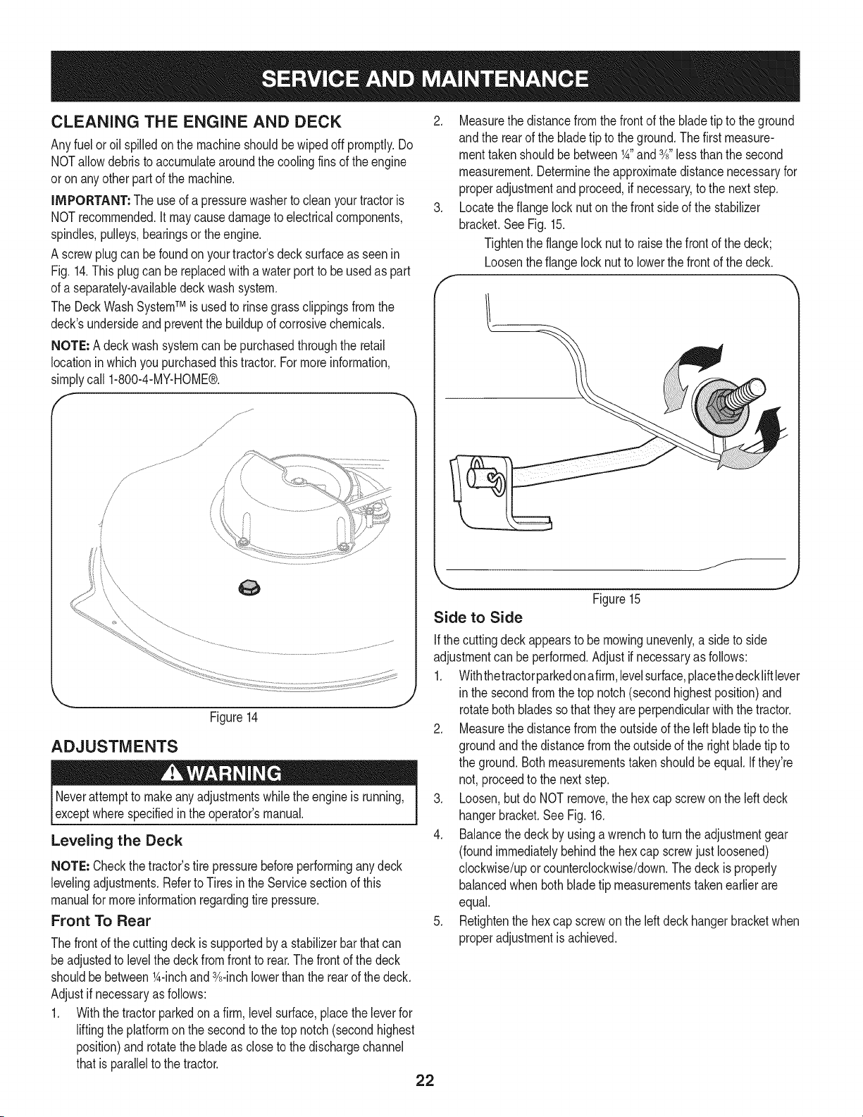
A screwplugcan be foundon yourtractor'sdecksurfaceas seenin
Fig. 14.Thisplugcanbe replacedwith a waterport to be usedas part
of a separately-availabledeck wash system.
The DeckWash SystemTM is usedto rinsegrassclippingsfromthe
deck'sundersideandpreventthe buildupof corrosivechemicals.
NOTE: Adeck wash systemcan bepurchasedthroughthe retail
locationinwhich youpurchasedthis tractor.For moreinformation,
simplycall 1-800-4-MY-HOME®.
/
/
Figure14
ADJUSTMENTS
Neverattemptto makeanyadjustmentswhilethe engineis running,
exceptwherespecifiedin the operator'smanual.
Leveling the Deck
NOTE: Checkthe tractor'stire pressurebeforeperforminganydeck
levelingadjustments.Referto Tires in the Servicesectionof this
manualfor moreinformationregardingtire pressure.
Front To Rear
2. Measurethedistancefromthe front of the bladetip to the ground
andthe rearof the bladetip to theground.Thefirst measure-
menttakenshouldbe between1A"and3A"less thanthe second
measurement.Determinethe approximatedistancenecessaryfor
properadjustmentandproceed,if necessary,to the nextstep.
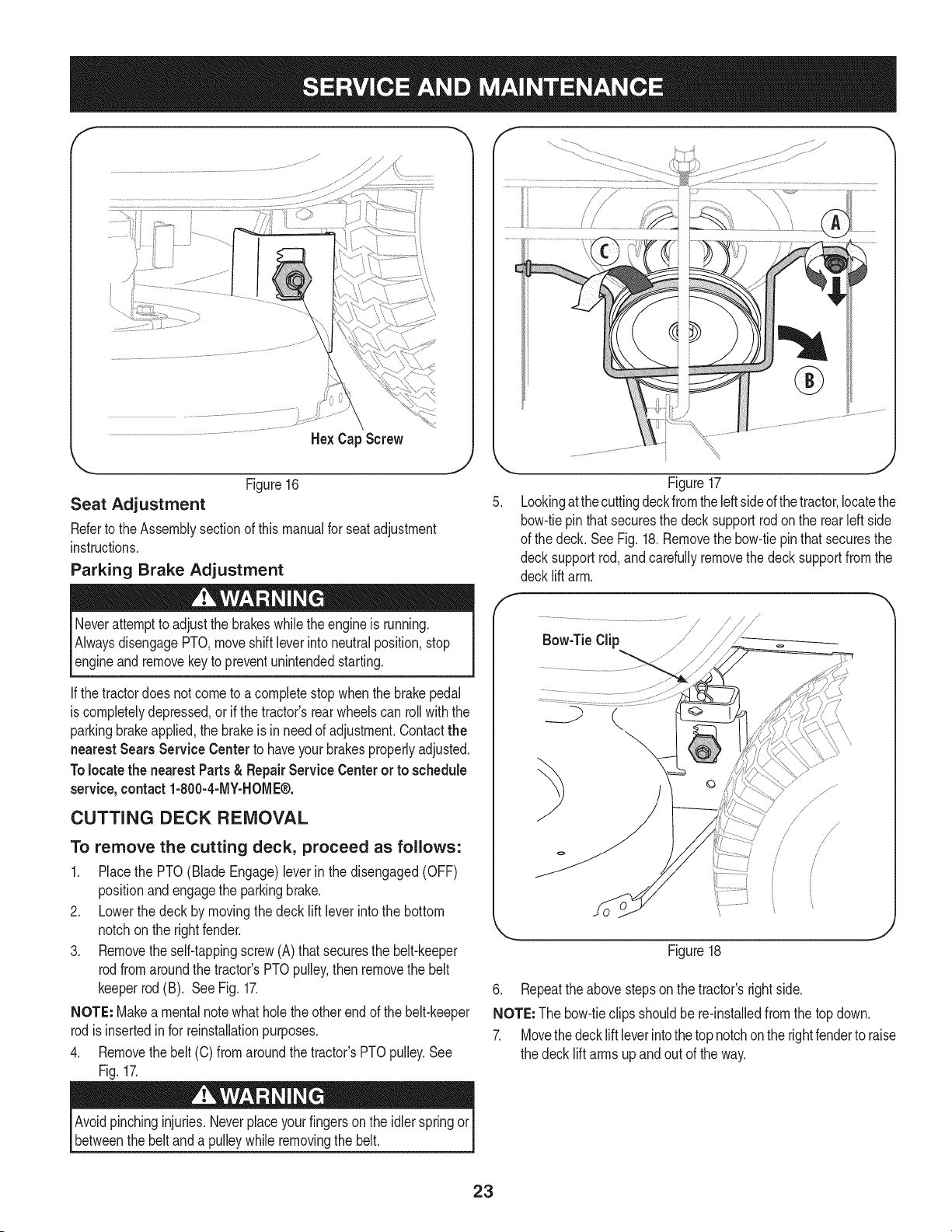
3. Locatethe flangelocknut onthe front sideof the stabilizer
bracket.SeeFig. 15.
Tightenthe flangelocknut to raisethe frontof the deck;
Loosentheflange locknutto lowerthefrontof thedeck.
Thefront of the cuttingdeckis supportedby a stabilizerbar that can
beadjustedto levelthe deckfromfrontto rear.Thefront of the deck
shouldbe between1A-inchand3A-inchlowerthan the rearof thedeck.
Adjustif necessaryas follows:
1. Withthe tractorparkedon a firm,levelsurface,placethe leverfor
liftingthe platformon the secondto the top notch(secondhighest
position)androtatethe bladeas close to the dischargechannel
thatis parallelto the tractor.
22
f
/
Figure15
Side to Side
Ifthe cuttingdeckappearsto be mowingunevenly,a sideto side
adjustmentcan be performed.Adjustif necessaryas follows:
1. Withthetractorparkedonafirm,levelsurface,placethedeckliftlever
in the secondfrom thetop notch(secondhighestposition)and
rotatebothbladessothattheyare perpendicularwith the tractor.
2. Measurethedistancefromthe outsideof the left bladetip to the
groundandthe distancefromthe outsideof the rightbladetip to
the ground.Bothmeasurementstakenshouldbeequal.Ifthey're
not, proceedto the nextstep.
3. Loosen,but do NOTremove,the hexcap screwon the left deck
hangerbracket.SeeFig. 16.
4. Balancethedeck by usinga wrenchto turn theadjustmentgear
(foundimmediatelybehindthehex cap screwjust loosened)
clockwise/uporcounterclockwise/down.Thedeckis properly
balancedwhen bothbladetip measurementstakenearlier are
equal.
5. Retightenthe hexcap screwon the leftdeckhangerbracketwhen
properadjustmentis achieved.
He× Cap Screw
'_. ._
Figure16
Seat Adjustment
Referto the Assemblysectionof thismanualfor seat adjustment
instructions.
Parking Brake Adjustment
Neverattemptto adjustthe brakeswhiletheengineis running.
AlwaysdisengagePTO,moveshift leverintoneutralposition,stop
engineandremovekeyto preventunintendedstarting.
If thetractordoes notcometo acompletestop whenthe brakepedal
is completelydepressed,or if the tractor'srearwheelscan rollwiththe
parkingbrakeapplied,the brakeis in needof adjustment.Contactthe
nearest Sears Service Center to haveyourbrakesproperlyadjusted.
Tolocatethe nearest Parts& Repair ServiceCenter or to schedule
service,contact 1-800-4-MY-HOME®.
CUTTING DECK REMOVAL
To remove the cutting deck, proceed as follows:
1. Placethe PTO(Blade Engage)leverin the disengaged(OFF)
positionand engagethe parkingbrake.
2. Lowerthe deck by movingthe deck lift lever intothe bottom
notchon the rightfender.
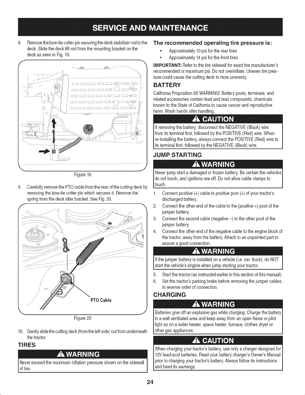
3. Removetheself-tappingscrew(A) that securesthe belt-keeper
rodfromaroundthe tractor'sPTOpulley,thenremovethe belt
keeperrod (B). SeeFig. 17.
NOTE: Makea mentalnotewhat holethe otherend of the belt-keeper
rodisinsertedin for reinstallationpurposes.
4. Removethebelt (C) fromaroundthetractor'sPTOpulley.See
Fig.17.
Figure17
5. Lookingatthecuttingdeckfrom theleftsideof thetractor,locatethe
bow-tiepin thatsecuresthe deck supportrod on the rearleft side
of the deck. See Fig. 18.Removethe bow-tiepinthat securesthe
decksupport rod,andcarefullyremovethe decksupportfromthe
decklift arm.
/
/
Bow-TieClip jj
/ /
/ /
/
/
i /
J
Figure18
6. Repeatthe abovestepson the tractor'srightside.
NOTE: The bow-tieclipsshouldbe re-installedfrom the top down.
7. Movethedecklift leverintothe topnotchon the rightfenderto raise
the deck lift arms up and out of theway.
Avoidpinchinginjuries.Neverplaceyourfingerson the idlerspringor
betweenthe belt anda pulleywhile removingthe belt.
23
8, Removethebow-tiecotterpinsecuringthedeck stabilizerrodto the
deck.Slide thedeck lift rodfrom the mountingbracketon the
deckasseen in Fig. 19.
............./1;_,_......................... / ..............................
_... j2
Figure19
.
f
Carefullyremovethe PTOcablefromthe rearof thecuttingdeckby
removingthe bow-tiecotter pinwhichsecuresit. Removethe
springfromthe deckidlerbracket.SeeFig.20.
PTOCable
Figure20
10. Gentlyslidethecuttingdeck(fromtheleftside)outfromunderneath
thetractor.
TIRES
Neverexceedthe maximuminflationpressureshownonthe sidewall
of tire.
The recommended operating tire pressure is:
• Approximately10psi for the reartires
• Approximately14psi for the fronttires
IMPORTANT: Referto the tire sidewaNfor exacttire manufacturer's
recommendedor maximumpsi. Donot overinflate.Uneventire pres-
surecould causethe cuttingdeckto mowunevenly.
BATTERY
CaliforniaProposition65 WARNING!Batteryposts,terminals,and
relatedaccessoriescontainleadandleadcompounds,chemicals
knownto the Stateof Californiato causecancer and reproductive
harm.Washhandsafter handling.
If removingthe battery,disconnectthe NEGATIVE(Black)wire
fromits terminalfirst,followedbythe POSITIVE(Red) wire.When
relinstallingthe battery,alwaysconnectthe POSITIVE(Red)wire to
Its termna f rst,fo owedby the NEGATVE (Back) w re.
JUMP STARTING
Neverjump starta damagedor frozenbattery.Be certain thevehicles
do not touch,and ignitionsare off. Do notallowcable clampsto
touch.
1. Connectpositive(+)cableto positivepost (+)of yourtractor's
dischargedbattery.
2. Connecttheotherendof thecableto the (positive+) postof the
jumperbattery.
3. Connectthesecondcable (negative-) to theother postof the
jumperbattery.
4. Connecttheotherendof thenegativecableto the engineblockof
the tractor,away fromthe battery.Attachto anunpaintedpartto
assurea goodconnection.
Ifthejumper batteryis installedona vehicle(i.e.car,truck),do NOT
startthe vehicle'senginewhenjump startingyourtractor.
5. Start thetractor(asinstructedearlierinthissectionofthismanual).
6. Set the tractor'sparkingbrakebeforeremovingthejumpercables,
in reverseorderof connection.
CHARGING
give off an explosivegas whilecharging.Chargethe batteryI
Batteries
ina wellventilatedareaand keepawayfroman openflame or pilot
ght as ona waterheater,spaceheater,furnace,c othesdryeror |
othergas appliances.
J
Whenchargingyourtractor'sbattery,useonlya chargerdesignedfor I
12Vlead-acidbatteries.Readyourbatterychargers Owners Manual
priorto chargingyourtractors battery.Alwaysfollowits instructions I
land heed ts warnngs. j
24
If yourtractorhasnot beenputinto usefor anextendedperiodof time,
chargethe batteryas follows:
1. Setyour batterychargerto delivera maxof 10amperes.
If yourbatterychargeris automatic,chargethe batteryuntilthe
chargerindicatesthatchargingis complete.Ifthe chargeris not
automatic,chargefor nofewerthaneight hours.
FUSE
One20 AMPfuseis installedin yourtractor'swiringharnessto protect
the tractor'selectricalsystemfromdamagecausedbyexcessive
amperage.
If theelectricalsystemdoesnot function,or yourtractor'senginewill
not crank,first checkto be certainthatthe fuse hasnot blown.It can
befoundat the rearof the unit, underneaththefenderlocatedby the
battery.
Alwaysusea fuse with the sameamperagecapacityfor replacement.
CUTTING BLADES
Shutthe engineoff andremoveignitionkeybeforeremovingthe
cuttingblade(s)for sharpeningor replacement.Protectyourhands
by usingheavygloveswhengraspingthe blade.
Periodicallyinspectthe bladeand/or spindlefor cracksordamage,
especiallyafter you'vestrucka foreignobject. Donot operatethe
machineuntil damagedcomponentsare replaced.
Toremovethe blades,proceedas follows.
1. Removethedeck from beneaththe tractor,(referto CuttingDeck
Removalearlierinthis section)thengently flip thedeck overto
exposeitsunderside.
2. Placea blockof woodbetweenthe centerdeckhousingbaffle
andthe cuttingbladeto actas a stabilizer.
SeeFig. 21.
f
©
Figure21
25
.
4.
Removethe hexflangenut thatsecuresthe bladeto the spindle
assembly.SeeFig.21.
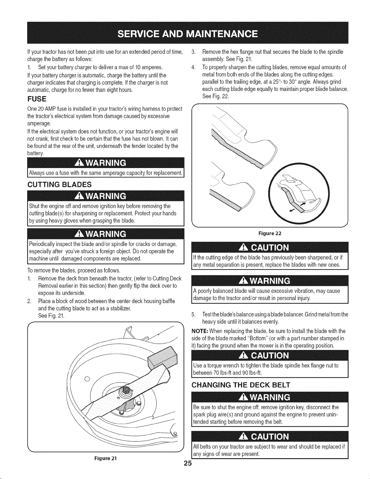
To properlysharpenthe cuttingblades,removeequalamountsof
metalfrombothendsof the bladesalongthe cuttingedges,
parallelto the trailingedge,at a250.to 300angle.Alwaysgrind
eachcutting bladeedgeequallyto maintainproperbladebalance.
SeeFig.22.
Figure 22
Ifthe cuttingedgeof the bladehas previouslybeensharpened,or if
any metalseparationis present,replacethe bladeswith newones.
A poorlybalancedbladewill causeexcessivevibration,maycause
damageto the tractorand/or resultin personalinjury.
5. Testtheblade'sbalanceusinga bladebalancer.Grindmetalfromthe
heavysideuntil it balancesevenly.
NOTE"Whenreplacingthe blade,be sureto installthe blade with the
sideof the blademarked"Bottom" (orwith a part numberstampedin
it)facing the groundwhenthe moweris in the operatingposition.
Usea torquewrenchto tightenthe bladespindlehexflangenut to
between70Ibs-ftand 90 Ibs-ft.
CHANGING THE DECK BELT
Besureto shut the engineoff, removeignitionkey,disconnectthe
Ispark plug wire(s)and ground againstthe engineto preventunin-
pnded startingbeforeremovingthe belt.
All beltsonyourtractorare subjectto wearandshouldbe replacedif
any signsof wearare present.
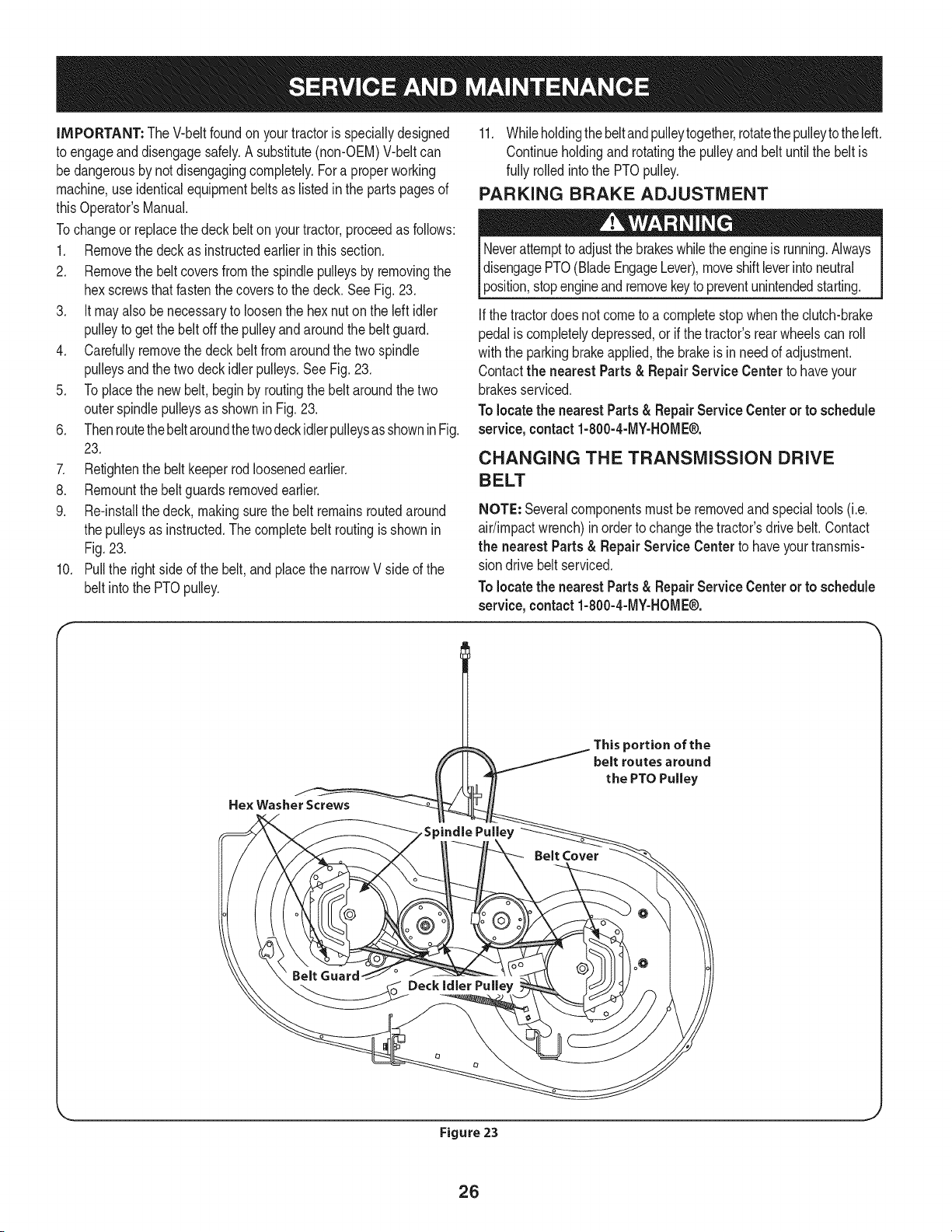
iMPORTANT: The V-beltfoundon yourtractoris speciallydesigned
to engageand disengagesafely.A substitute(non-OEM)V-beltcan
bedangerousby notdisengagingcompletely.Fora properworking
machine,useidenticalequipmentbeltsas listedin the partspagesof
thisOperator'sManual.
Tochangeor replacethe deckbelt on yourtractor,proceedas follows:
1. Removethe deckas instructedearlier inthis section.
2. Removethe beltcoversfrom the spindlepulleysby removingthe
hexscrewsthat fastenthecoversto the deck.SeeFig. 23,
3. it mayalso be necessaryto loosenthe hex nuton the leftidler
pulleyto getthe belt off the pulleyand aroundthe beltguard.
4. Carefullyremovethe deckbeltfrom aroundthe twospindle
pulleysandthetwo deckidler pulleys,See Fig, 23,
5. Toplacethe newbelt,beginby routingthe belt aroundthe two
outerspindlepulleysas shownin Fig.23,
6. ThenroutethebeltaroundthetwodeckidlerpulleysasshowninFig.
23.
7. Retightenthe belt keeperrodloosenedearlier.
8. Remountthebelt guardsremovedearlier,
9. Re-installthedeck, makingsurethe belt remainsroutedaround
the pulleysas instructed.Thecompletebelt routingisshownin
Fig,23.
10. Pull the rightside ofthe belt,and placethe narrowV side of the
belt intothe PTOpulley.
11. Whileholdingthe beltandpulleytogether,rotatethepulleytotheleft.
Continueholdingandrotatingthe pulleyandbelt untilthe belt is
fully rolledintothe PTOpulley.
PARKING BRAKE ADJUSTMENT
Neverattemptto adjustthe brakeswhiletheengineis running.Always
disengagePTO(BladeEngageLever),moveshiftleverintoneutral
position,stopengineandremovekeyto preventunintendedstarting.
Ifthe tractordoesnot cometo a completestop whenthe clutch-brake
pedalis completelydepressed,or if the tractor'srearwheelscan roll
withthe parkingbrakeapplied,the brakeis inneedof adjustment.
Contactthe nearest Parts& RepairService Centerto haveyour
brakesserviced.
Tolocatethe nearestParts& RepairService Center or to schedule
service,contact1-800-4-MY-HOME®.
CHANGING THE TRANSMiSSiON DRIVE
BELT
NOTE: Severalcomponentsmust beremovedandspecialtools(i.e.
air/impactwrench)inorder to changethetractor'sdrivebelt. Contact
the nearest Parts& Repair Service Centerto haveyourtransmis-
sion drivebelt serviced.
Tolocatethe nearestParts& RepairService Center or to schedule
service, contact 1-800-4-MY-HOME®.
Figure 23
26
Neverstorelawntractorwithfuel intankindoorsorin poorly
ventilatedareaswherefuel fumesmay reachan open flame,spark,
orpilot lightas ona furnace,waterheater,clothesdryer,or gas
appliance.
PREPARING THE ENGINE
IMPORTANT:Fuelleftin thefuel tankduringwarmweatherdeterio-
ratesandwill causeseriousstartingproblems.
To preventgumdepositsfromforminginsidethe engine'scarburetor
andcausingpossiblemalfunctionof theengine,thefuel systemmust
be eithercompletelyemptied,orthe gasolinemustbe treatedwith a
stabilizerto preventdeterioration.
1. If usingafuel stabilizer:
a. Readthe productmanufacturer'sinstructionsandrecom-
mendations.
b. Add to clean,freshgasolinethe correctamountof stabilizer
for the capacityof the fuel system.
c. Fillthe fueltank with treatedfuel andrun the enginefor 2-3
minutesto get stabilizedfuel intothe carburetor.
2. Ifemptyingthe fuel system:
a. Donot drainfuel whenthe engineis hot.Allowthe engine
adequatetime to cool.Drainfuelinto an approvedcontainer
outdoors,awayfrom open flame.
b. Drainany largevolumeof fuel from thetank bydisconnect-
ing thefuel linefromthe in-linefuel filternearthe engine.
Seethe completeinstructionsfor DrainingThe Fuellaterin
this section.
Gasolineis extremelyflammableand can beexplosiveundercertain
conditions.Draingasolinebeforestoringthe equipmentfor extended
periods.Drainfuel only intoan approvedcontaineroutdoors,away
froman openflame.Allowengineto cool.Extinguishcigarettes,
cigars,pipes, and othersourcesof ignitionprior to drainingfuel.
Storegasolinein an approvedcontainerin safe location.
c. Reconnectthe fuel lineand run the engineuntil it startsto
falter,thenuse thechoketo keeptheengine runninguntilall
fuel in thecarburetorhas beenexhausted.
d. Disconnectthefuel lineanddrainany remaininggasoline
fromthe system.
DRAiNiNG THE FUEL
1. Locatethe fuel filter,which is locatedonthe left sideof the
engine,and maybe attachedto the enginewitha tie strap.
2. Cutthe tie strap,if present,then pinchthe in-lineclamp on the
fuel filter with a pair of pliers,slidethe clampup the fuel line.
3. Pullthe fuel linefreefrom the filterandplacethe open end of the
lineintoan approvedcontainerto drainthe fuel.
PREPARING THE LAWN TRACTOR
1. Cleanand lubricatetractorthoroughlyas describedin the lubrica-
tion instructions.
2. Donot usea pressurewasheror gardenhoseto cleanyour unit.
3. Storemowerin a dry,cleanarea. Do notstorenextto corrosive
materials,suchas fertilizer.
Gasolineis a toxicsubstance.Disposeof gasolineproperly.Contact
your localauthoritiesfor approveddisposalmethods.
3. Removethe sparkplugand pour one (1) ounceof engineoil
throughthe sparkplughole intothe cylinder.Cranktheengine
severaltimesto distributethe oil. Replacethe spark plug.
27
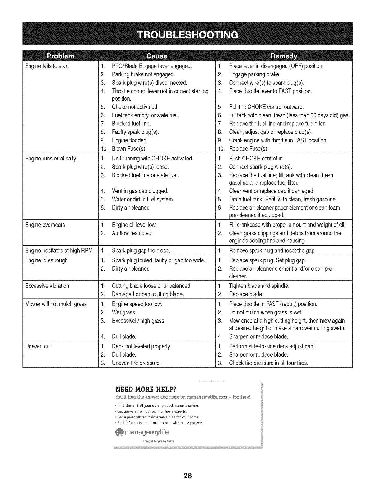
Enginefailsto start
Enginerunserratically
1. PTO/BladeEngageleverengaged.
2. Parkingbrakenotengaged.
3. Sparkplugwire(s)disconnected.
4. Throttlecontrollevernot in correctstarting
position.
5. Chokenotactivated
6. Fueltankempty,or stalefuel.
7. Blockedfuel line.
8. Faultyspark plug(s).
9. Engineflooded.
10. BlownFuse(s)
1. Unit runningwith CHOKEactivated.
2. Sparkplugwire(s)loose.
3. Blockedfuel lineor stalefuel.
4. Ventin gas cap plugged.
5. Wateror dirt infuel system.
6. Dirtyair cleaner.
Engineoverheats 1. Engineoil levellow. 1.
2. Air flowrestricted. 2.
Enginehesitatesat highRPM 1. Sparkpluggaptoo close. 1.
Engineidles rough 1. Sparkplugfouled,faultyor gaptoo wide. 1.
2. Dirtyair cleaner. 2.
Excessivevibration
Mowerwill not mulchgrass
Unevencut
1. Cuttingbladelooseor unbalanced.
2. Damagedor bentcuttingblade.
1. Enginespeedtoo low.
2. Wetgrass.
3. Excessivelyhigh grass.
4. Dullblade.
1. Decknot leveledproperly.
2. Dullblade.
3. Uneventire pressure.
1. Placeleverindisengaged(OFF) position.
2. Engageparkingbrake.
3. Connectwire(s)to sparkplug(s).
4. Placethrottleleverto FASTposition.
5. Pullthe CHOKEcontroloutward.
6. Filltankwith clean,fresh (less than30 daysold) gas.
7. Replacethe fuel line and replacefuel filter.
8. Clean,adjustgap or replaceplug(s).
9. Crankenginewith throttlein FASTposition.
10. ReplaceFuse(s)
1. PushCHOKEcontrol in.
2. Connectspark plugwire(s).
3. Replacethe fuel line;fill tankwithclean,fresh
gasolineandreplacefuel filter.
4. Clearventor replacecap if damaged.
5. Drainfuel tank. Refillwith clean,fresh gasoline.
6. Replaceair cleanerpaperelementor cleanfoam
pre-cleaner,if equipped.
Fillcrankcasewith properamountand weightof oil.
Cleangrassclippingsanddebrisfrom aroundthe
engine'scoolingfins and housing.
Removesparkplugand resetthe gap.
Replacesparkplug.Set pluggap.
Replaceair cleanerelementand/orclean pre-
cleaner.
1. Tightenbladeand spindle.
2. Replaceblade.
1. Placethrottlein FAST(rabbit)position.
2. Do notmulchwhengrassis wet.
3. Mowonce at a highcuttingheight,then mowagain
at desiredheightor makea narrowercuttingswath.
4. Sharpenor replaceblade.
1. Performside-to-sidedeck adjustment.
2. Sharpenor replaceblade.
3. Checktire pressureinallfour tires.
NEED MORE HELP?
Find this and aLLyour other product manuals online,
Get answers from our team of home experts.
Get a personalized maintenance plan for your home,
Find information and tools to help with home projects.
_o #At 1o ye b:_ Sea_s
28
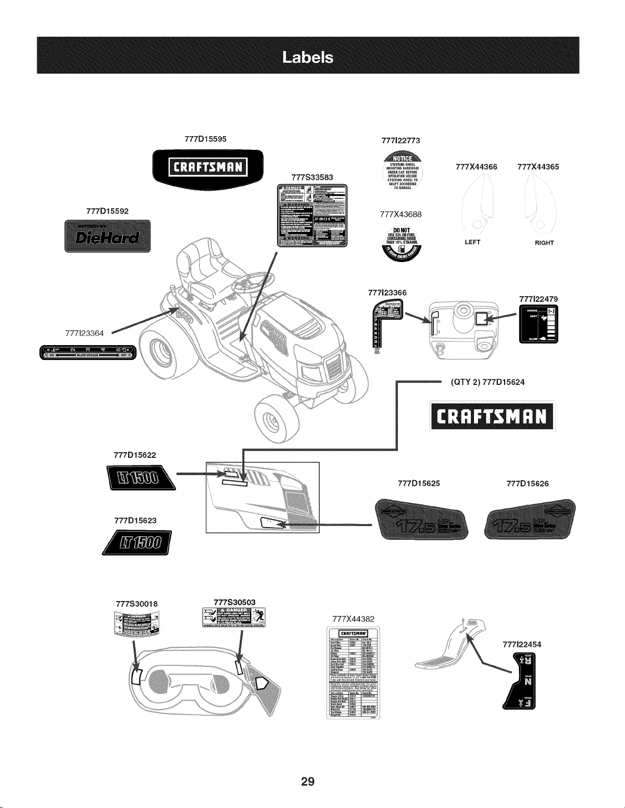
777D15592
777D15595 777122773
777S33583
STEERINGWHEEL
MOUHTIN6HARDWARE
UHDER CAR BEFORE
OPERATIOHSECURE
STEERIHGWHEELTO
SHAFT ACCORDING
TOMAHUAL
777X43688
DONOT
USE E85 ORFUEL
CONTAININGMORE
THAN 10% E]}IAHAL
777X44366 777X44365
LEFT RIGHT
777J23366
777122479
777123364
(QTY 2) 777D15624
777D15622
777D15625
777D15626
777D15623
777S30018
777S30503
777X44382
i
29
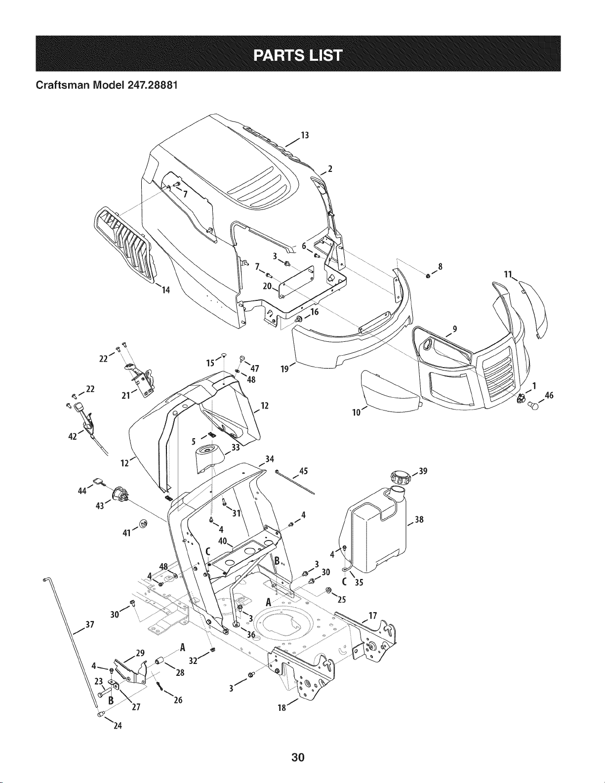
Craftsman IViodel 247.28881
/22 21
19
12
17
_f 39
1.38
3O
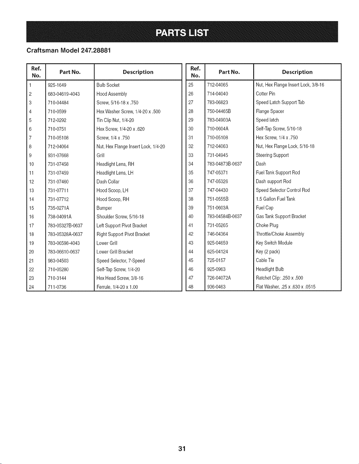
Craftsman IViodel 247.28881
Ref. I
No,
1 925-1649
2 683-04619-4043
3 710-04484
4 710-0599
5 712-0292
6 710-0751
7 710-05108
8 712-04064
9 931-07668
10 731-07458
11 731-07459
12 731-07460
13 731-07711
14 731-07712
15 735-0271A
16 738-04091A
17 783-05327B-0637
18 783-05328A-0637
19 783-06598-4043
20 783-06610-0637
21 983-04503
22 710-05280
23 710-3144
24 711-0736
Part No. Description
BulbSocket
HoodAssembly
Screw,5/16-18x .750
HexWasherScrew,1/4-20x .500
Tin Clip Nut, 1/4-20
HexScrew,1/4-20x .620
Screw,1/4 x .750
Nut,HexFlangeInsertLock,1/4-20
Grill
HeadlightLens,RH
HeadlightLens,LH
DashCollar
HoodScoop,LH
HoodScoop,RH
Bumper
ShoulderScrew,5/16-18
LeftSupportPivotBracket
RightSupportPivotBracket
LowerGrill
LowerGrill Bracket
SpeedSelector,7-Speed
Self-TapScrew,1/4-20
HexHeadScrew,3/8-16
Ferrule,1/4-20x 1.00
Ref. I
No,
25 712-04065
26 714-04040
27 783-06823
28 750-04465B
29 783-04903A
30 710-0604A
31 710-05108
32 712-04063
33 731-04945
34 783-04873B-0637
35 747-05371
36 747-05326
37 747-04430
38 751-0555B
39 751-0603A
40 783-04584B-0637
41 731-05265
42 746-04364
43 925-04659
44 625-04124
45 725-0157
46 925-0963
47 726-04072A
48 936-0463
Part No. Description
Nut, HexFlangeInsertLock,3/8-16
Cotter Pin
SpeedLatchSupportTab
FlangeSpacer
Speedlatch
Self-TapScrew,5/16-18
HexScrew,1/4x .750
Nut, HexFlangeLock,5/16-18
SteeringSupport
Dash
FuelTankSupport Rod
Dashsupport Rod
SpeedSelectorControl Rod
1.5GallonFuelTank
FuelCap
GasTankSupportBracket
ChokePlug
Throttle/ChokeAssembly
KeySwitchModule
Key(2 pack)
CableTie
HeadlightBulb
RatchetClip: .250x .500
FlatWasher,.25 x .630x .0515
31
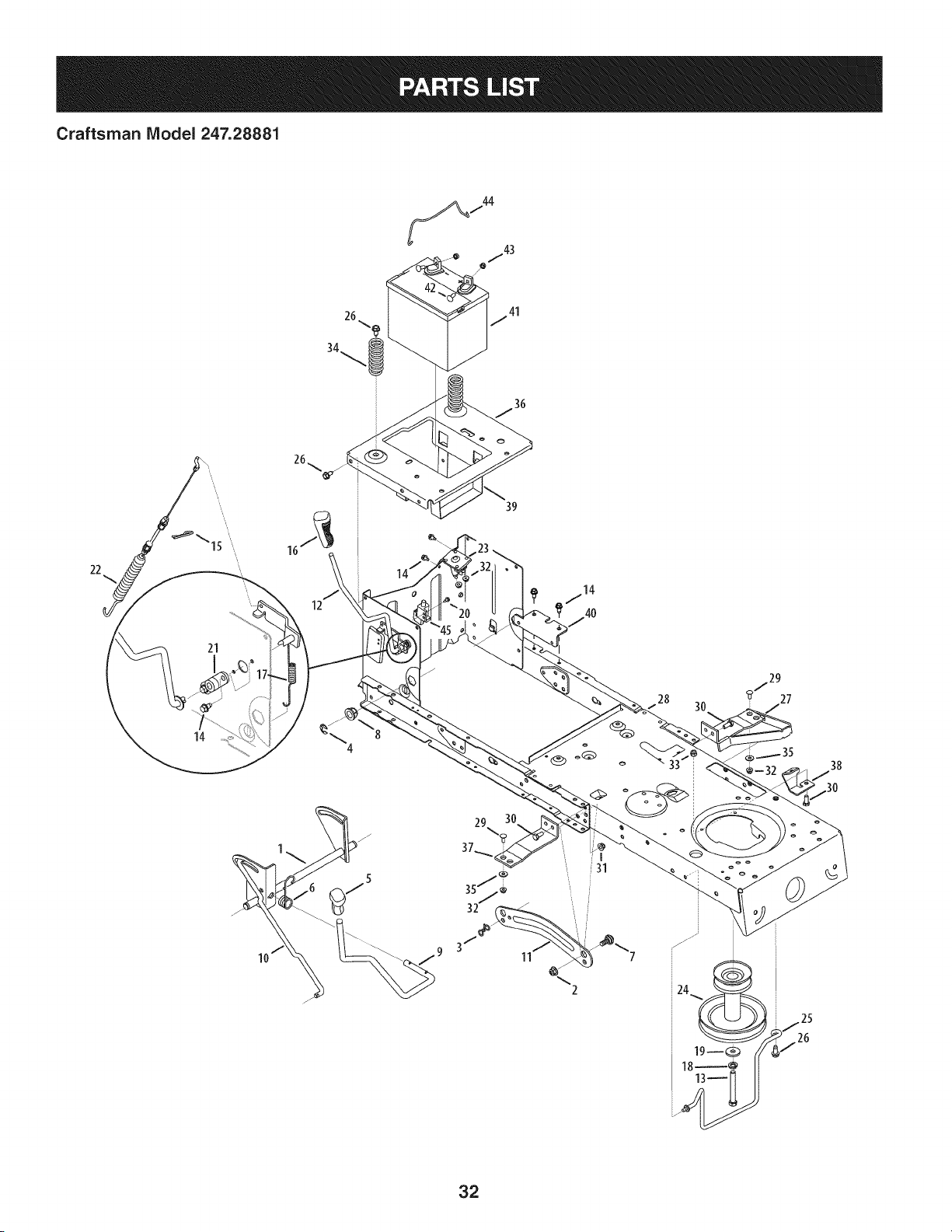
Craftsman IViodel 247.28881
22
14
12
39
11
2
32
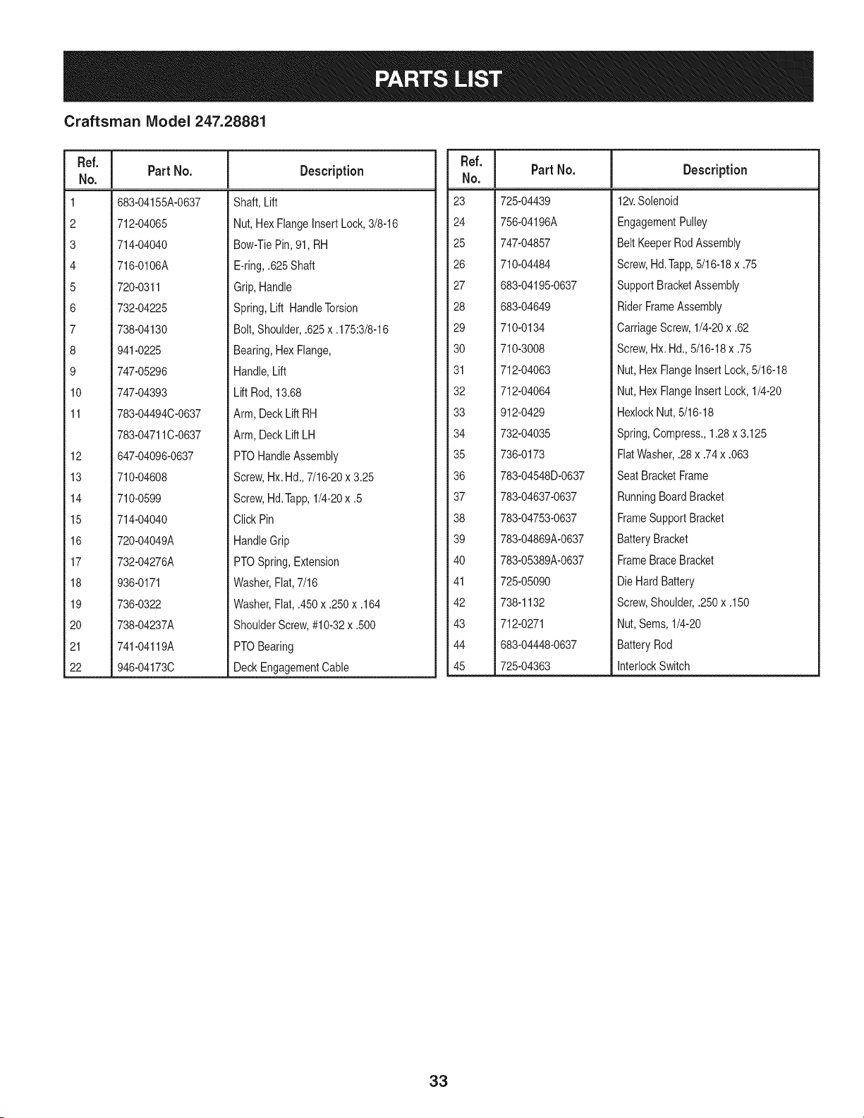
Craftsman IViodel 247.28881
Ref. I
No.
1 683-04155A-0637
2 712-04065
3 714-04040
4 716-0106A
5 720-0311
6 732-04225
7 738-04130
8 941-0225
9 747-05296
10 747-04393
11 783-04494C-0637
783-04711C-0637
12 647-04096-0637
13 710-04608
14 710-0599
15 714-04040
16 720-04049A
17 732-04276A
18 936-0171
19 736-0322
20 738-04237A
21 741-04119A
22 946-04173C
PartNo. Description
Shaft, Lift
Nut, HexFlangeInsertLock,3/8-16
Bow-TiePin,91, RH
E-ring,.625Shaft
Grip,Handle
Spring,Lift HandleTorsion
Bolt, Shoulder,.625x .175:3/8-16
Bearing,HexFlange,
Handle,Lift
Lift Rod,13.68
Arm, DeckLift RH
Arm, DeckLift LH
PTOHandleAssembly
Screw,Hx. Hd.,7/16-20x 3.25
Screw,Hd.Tapp,1/4-20x .5
Click Pin
HandleGrip
PTOSpring,Extension
Washer,Flat,7/16
Washer,Fiat, .450x .250x .164
ShoulderScrew,#10-32x .500
PTOBearing
DeckEngagementCable
Ref. I
No.
23 725-04439
24 756-04196A
25 747-04857
26 710-04484
27 683-04195-0637
28 683-04649
29 710-0134
30 710-3008
31 712-04063
32 712-04064
33 912-0429
34 732-04035
35 736-0173
36 783-04548D-0637
37 783-04637-0637
38 783-04753-0637
39 783-04869A-0637
40 783-05389A-0637
41 725-05090
42 738-1132
43 712-0271
44 683-04448-0637
45 725-04363
Part No. Description
12v.Solenoid
EngagementPulley
Belt KeeperRodAssembly
Screw,Hd.Tapp,5/16-18x .75
SupportBracketAssembly
RiderFrameAssembly
CarriageScrew,1/4-20x .62
Screw,Hx. Hd.,5/16-18x .75
Nut, HexFlangeInsert Lock,5/16-18
Nut, HexFlangeInsert Lock,1/4-20
HexlockNut,5/16-18
Spring,Compress.,1.28x 3.125
FlatWasher,.28 x .74x .063
SeatBracketFrame
RunningBoardBracket
FrameSupportBracket
BatteryBracket
FrameBraceBracket
Die HardBattery
Screw,Shoulder,.250x .150
Nut,Sems, 1/4-20
BatteryRod
InterlockSwitch
33
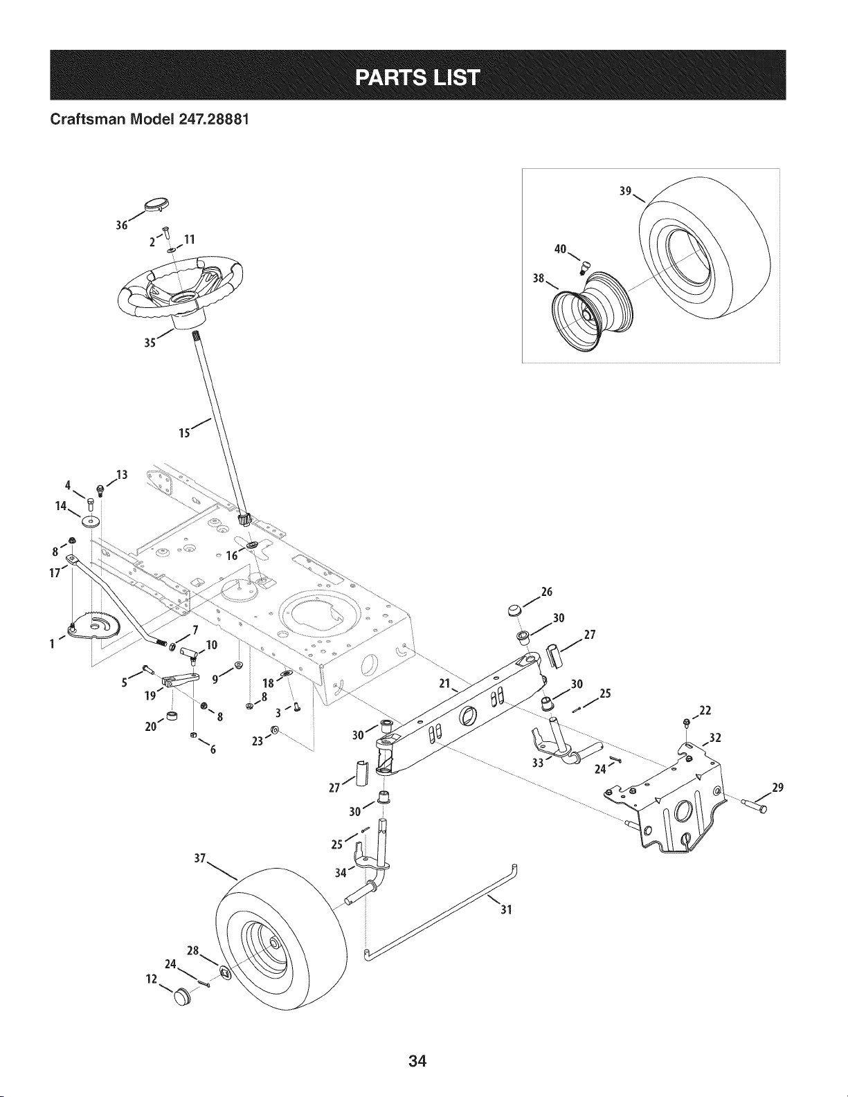
Craftsman IViodel 247.28881
21
30
25
22
................ 33 _ /_ ........................
34
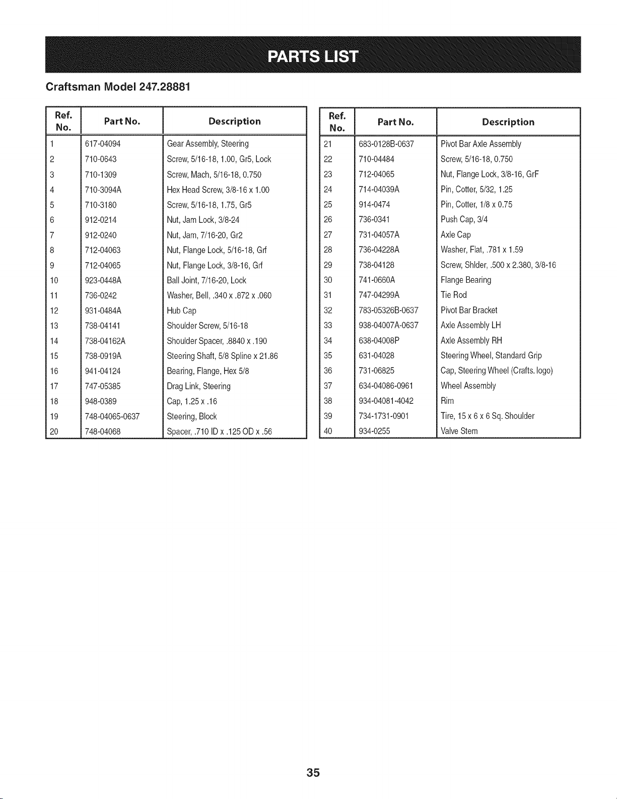
Craftsman IViodel 247.28881
Ref, I
No,
1 617-04094
2 710-0643
3 710-1309
4 710-3094A
5 710-3180
6 912-0214
7 912-0240
8 712-04063
9 712-04065
10 923-0448A
11 736-0242
12 931-0484A
13 738-04141
14 738-04162A
15 738-0919A
16 941-04124
17 747-05385
18 948-0389
19 748-04065-0637
20 748-04068
Part No. Description
GearAssembly,Steering
Screw,5/16-18,1.00,Gr5,Lock
Screw,Mach,5/16-18,0.750
HexHeadScrew,3/8-16x 1.00
Screw,5/16-18,1.75,Gr5
Nut,JamLock,3/8-24
Nut,Jam,7/16-20,Gr2
Nut,FlangeLock,5/16-18,Grf
Nut,FlangeLock,3/8-16,Grf
BallJoint,7/16-20,Lock
Washer,Bell, .340x .872x .060
HubCap
ShoulderScrew,5/16-18
ShoulderSpacer,.8840 x.190
SteeringShaft,5/8 Splinex 21.86
Bearing,Flange,Hex5/8
DragLink,Steering
Cap, 1.25x .16
Steering,Block
Spacer,.710ID x .125OD x .56
Ref, I
NO,
21 683-0128B-0637
22 710-04484
23 712-04065
24 714-04039A
25 914-0474
26 736-0341
27 731-04057A
28 736-04228A
29 738-04128
30 741-0660A
31 747-04299A
32 783-05326B-0637
33 938-04007A-0637
34 638-04008P
35 631-04028
36 731-06825
37 634-04086-0961
38 934-04081-4042
39 734-1731-0901
40 934-0255
Part No. Description
PivotBarAxle Assembly
Screw,5/16-18,0.750
Nut, FlangeLock,3/8-16,GrF
Pin, Cotter,5/32, 1.25
Pin, Cotter,1/8 x 0.75
PushCap,3/4
AxleCap
Washer,Fiat,.781x 1.59
Screw,Shlder,.500x 2.380,3/8-16
FlangeBearing
Tie Rod
PivotBar Bracket
AxleAssemblyLH
AxleAssemblyRH
SteeringWheel,StandardGrip
Cap,SteeringWheel (Crafts.logo)
WheelAssembly
Rim
Tire, 15 x 6 x 6 Sq.Shoulder
ValveStem
35
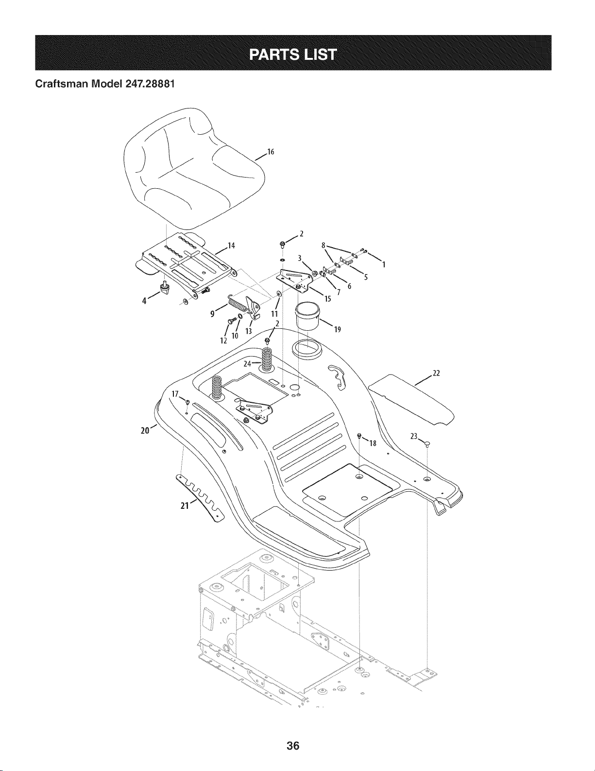
Craftsman IViodel 247.28881
\
36
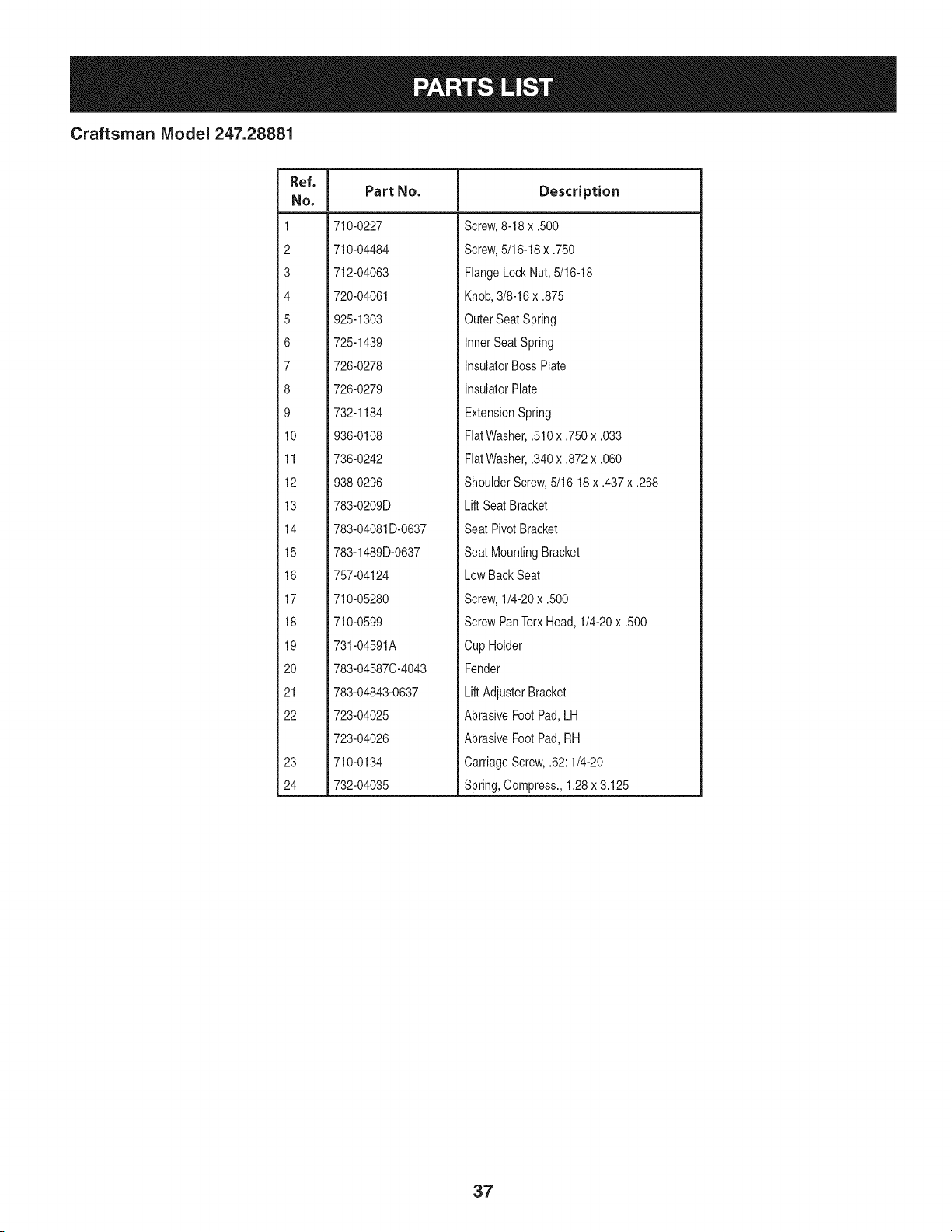
Craftsman IViodel 247.28881
Ref. I
No,
1 710-0227
2 710-04484
3 712-04063
4 720-04061
5 925-1303
6 725-1439
7 726-0278
8 726-0279
9 732-1184
10 936-0108
11 736-0242
12 938-0296
13 783-0209D
14 783-04081D-0637
15 783-1489D-0637
16 757-04124
17 710-05280
18 710-0599
19 731-04591A
20 783-04587C-4043
21 783-04843-0637
22 723-04025
723-04026
23 710-0134
24 732-04035
Part No. Description
Screw,8-18 x .500
Screw,5/16-18x .750
FlangeLockNut, 5/16-18
Knob,3/8-16x .875
OuterSeat Spring
InnerSeatSpring
InsulatorBossPlate
InsulatorPlate
ExtensionSpring
FiatWasher,.510x .750x .033
FlatWasher,.340x .872x .060
ShoulderScrew,5/16-18x .437x .268
Lift SeatBracket
Seat PivotBracket
Seat MountingBracket
Low BackSeat
Screw,1/4-20x .500
ScrewPanTorxHead,1/4-20x .500
Cup Holder
Fender
Lift AdjusterBracket
AbrasiveFootPad,LH
AbrasiveFootPad,RH
CarriageScrew,.62:1/4-20
Spring,Compress.,1.28x 3.125
37
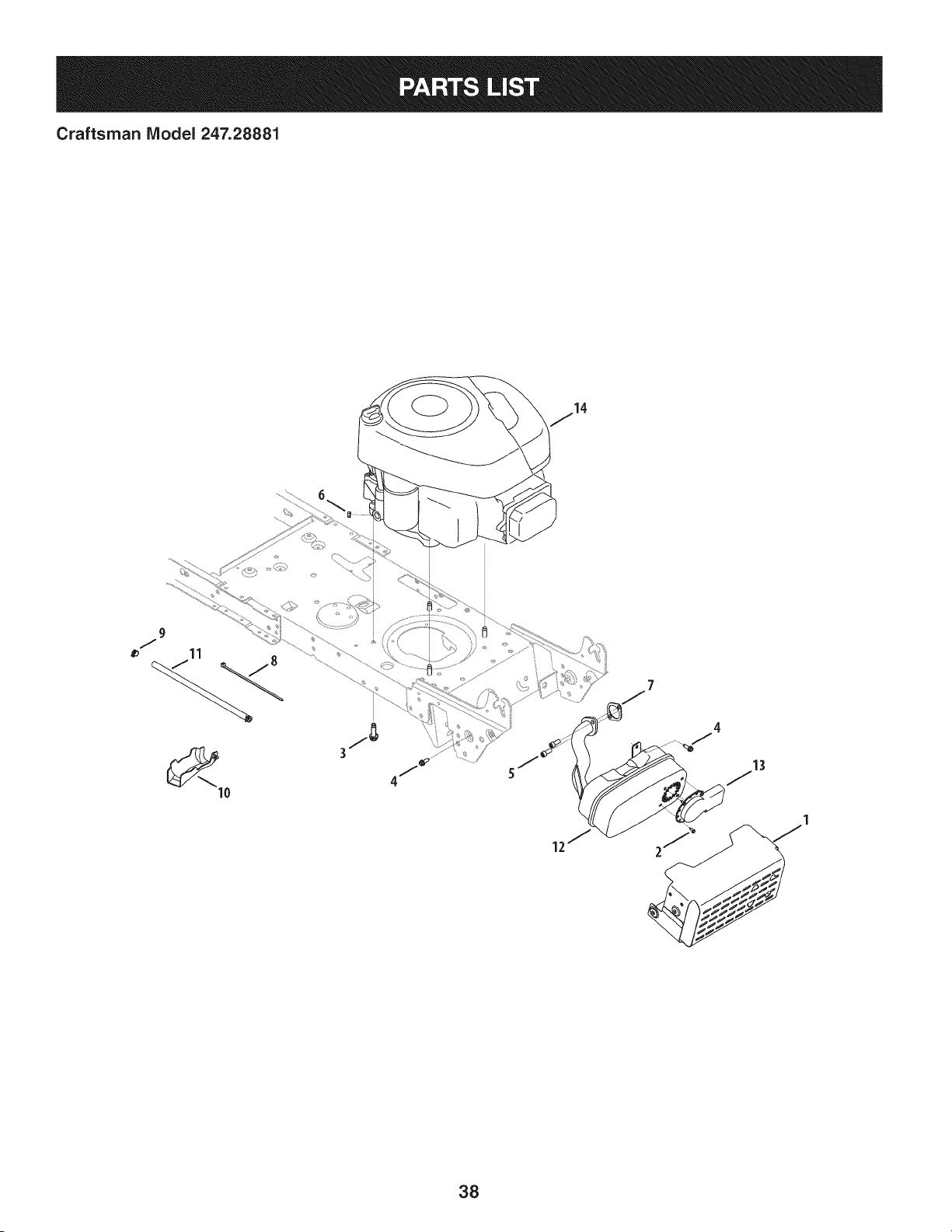
Craftsman IViodel 247.28881
38
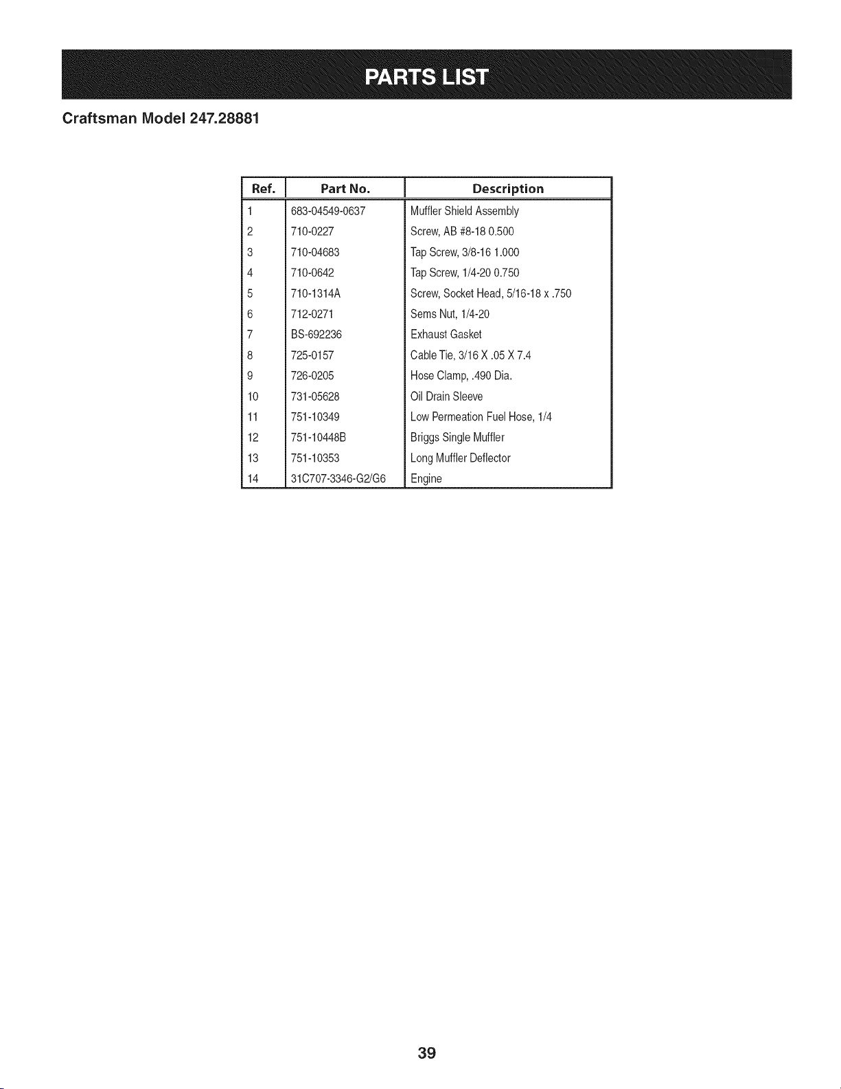
Craftsman IViodel 247.28881
I
Ref. I Part No.
1 683-04549-0637
2 710-0227
3 710-04683
4 710-0642
5 710-1314A
6 712-0271
7 BS-692236
8 725-0157
9 726-0205
10 731-05628
11 751-10349
12 751-10448B
13 751-10353
14 31C707-3346-G2/G6
Description
MufflerShieldAssembly
Screw,AB #8-180.500
TapScrew,3/8-16 1.000
TapScrew,1/4-200.750
Screw,SocketHead,5/16-18x .750
Sems Nut, 1/4-20
ExhaustGasket
CableTie,3/16 X .05 X 7.4
HoseClamp,.490 Dia.
Oil DrainSleeve
LowPermeationFuelHose,1/4
BriggsSingleMuffler
LongMufflerDeflector
Engine
39

Craftsman Model 247.28881
18
8
27
38
6O
62
\
23
47
1 "
> 28
4O

Craftsman IViodel 247.28881
Ref, I
NO,
1 918-04566
2 647-04034C-0637
3 647-04035
4 710-0227
5 710-04484
6 710-0599
7 710-0604A
8 710-0809
9 710-0176
10 710-3008
11 911-04075A
12 712-04063
13 712-0700
14 914-0209
15 714-04040
16 718-04407
17 720-04028
18 725-0157
19 725-1644
20 726-0214
21 926-0320
22 731-04602
23 731-04604
24 731-06894
25 732-04306
26 732-04488
27 732-04746
28 732-0716D
29 735-0239
30 736-0242
31 747-04969
32 747-05186
Part No. Description
TransmissionDriveAssembly
PedalAssembly
Shaft LeverAssembly
Screw,8-18:0.500
Screw,5/16-18x .750
Screw,1/4-20x 0.500
Screw,5/16-18x 0.625
Screw,1/4-20x 1.250
HexScrew,5/16-18x 2.75
HexScrew,5/16-18x .75
Ferrule,3/8-24X .375DIA.
FlangelockNut, 5/16-18
FlangeNut, 9/16-18
Cotter Pin INT-.125DIA
Bow-TieCotter Pin
PulleyHub,5/8SPLINE
Shift Knob
CableTie
Short SpringSwitch
PushCap,5/8
PlateInsulatorNut
Sleeve,.758x .821x 3.3125
Sleeve,.758x .821x 2.4375
Shift BearingPlate
SpringExtension,.80ODx 3.28LG
SpringExtension,.38ODx 3.25LG
SpringExtension,.94ODx 6.75LG
SpringExtension,.59ODx 4.00LG
FootPad,4.0 LONG
BellWasher,.340x .872x .060
Belt KeeperRod
VariableSpeedControl Rod
Ref. I
No,
33 747-05188
34 747-05244
35 738-04237A
36 750-0566A
37 750-0802
38 954-04249
39 954-0241A
40 956-04002
41 783-04536B-0637
42 783-04595A
43 956-04015A
44 683-04206
45 710-0627
46 710-0778
47 718-04261
48 736-0362
49 941-0600
50 683-04176A
51 683-04207
52 710-0347
53 710-1260A
54 712-04065
55 938-0347
56 756-04325
57 725-04363
58 17962
59 634-0104
60 634-04369-4042
61 934-0255
62 734-1730
-- 925-04082
Part No. Description
BrakeRod
Shift Rod
ShoulderScrew,#10-32x .500
Spacer,.260 x .375x 1.030LG
Spacer,.640 IDx .76OD x 2.63
V Belt, 5L:70.90 POLY
V Belt, 5L:35.25 POLY
Trans.Pulley
PedalSupportBracket
ShaftAdjustBracket
VariableSpeed PulleyAssembly
BracketAssembly
HexScrew,5/16-24x .750
Screw,1/4-20x 1.500
BearingCup
FlatWasher,.330x 1.25x .06:HT
Ball Bearing,17x 40x 12
TransmissionBracketAssembly
Idler BracketAssembly
HexScrew,3/8-16x 1.75
Screw,5/16-18x 0.750
FlangeLockNut, 3/8-16
ShoulderSpacer,.625IDx .169
Idler Pulley
SwitchInterlock
PlateSwitch
WheelAssembly,20 x 8 x 8 Sq. Sh.
RimAssembly
ValveStem
Tire, 20 x 8 x 8 Sq.Sh.
WiringHarness(Not Shown)
41
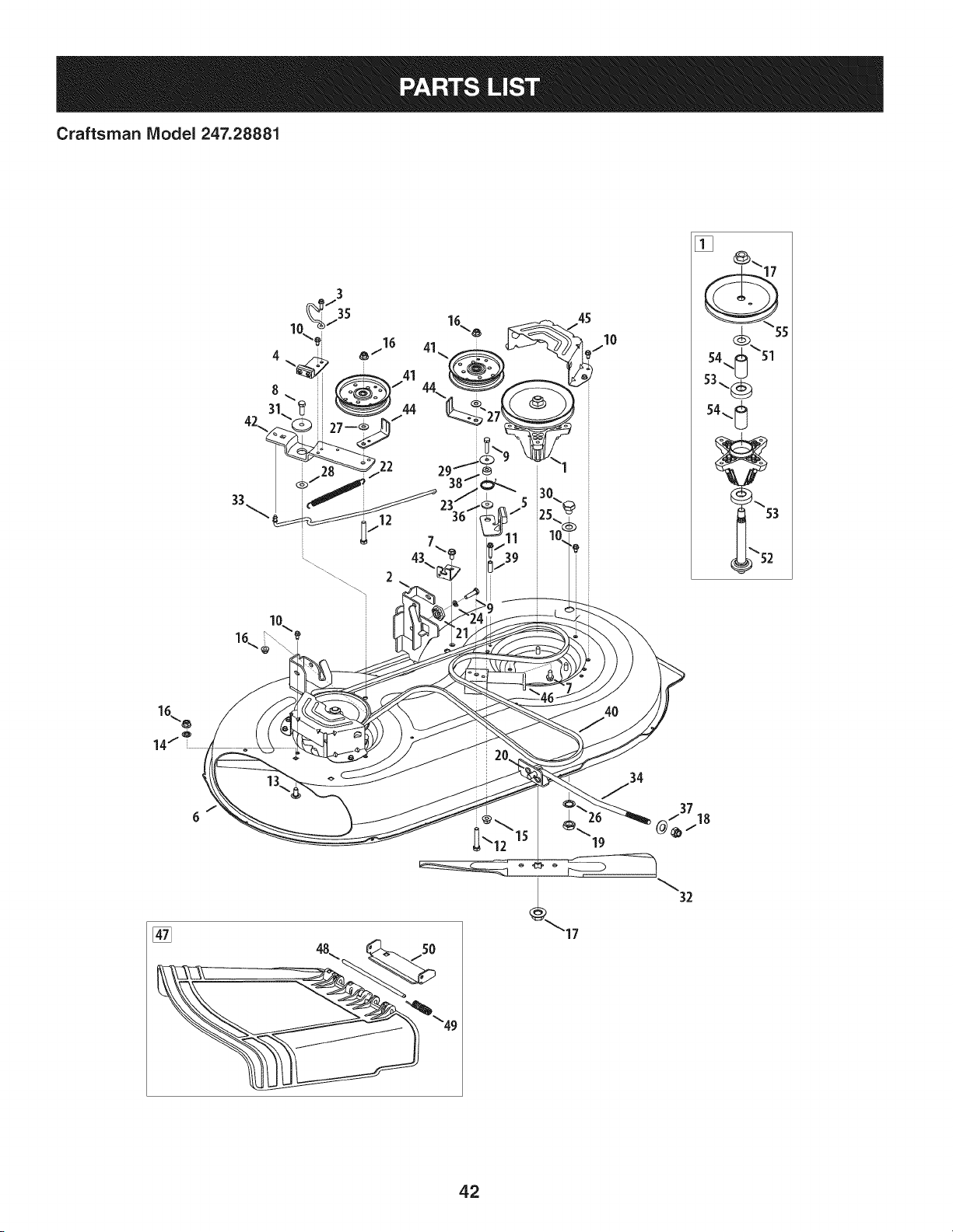
Craftsman IViodel 247.28881
42\
[]
19
32
42

Craftsman IViodel 247.28881
Ref, I
No,
1 918-04822A
2 683-0254B-0637
3 710-0642
4 983-04511
5 983-04525
6 983-04570-0637
7 710-04484
8 710-0514
9 710-0528
10 710-0599
11 710-0778
12 710-3144
13 710-3178
14 712-0229
15 712-04063
16 712-04065
17 712-0417A
18 712-04243
19 912-0641
20 714-04043
21 917-04074
22 932-0384
23 732-04727
24 936-0119
25 736-0187
26 736-0225
27 736-0262
28 936-0344
Part No. Description
SpindlePulleyAssembly
DeckHangerBracketAssembly
Screw,1/4-20x .750
BrakeAssembly
BrakeAssembly
Deck
Screw,5/16-18x .750
Screw,3/8-16x 1.00
HexScrew,5/16-18x 1.25
Screw,1/4-20x .500
Screw,1/4-20x 1.50
HexHeadScrew,3/8-16
CarriageBolt, 3/8-16x .75
PushNut,3/8
FlangelockNut, 5/16-18
FlangelockNut, 3/8-16
FlangeNut, 5/8-18
FlangelockNut, 1/2-13
HexNut,M16- 1.5
CotterPin, Bow-Tie
DeckAdjusterGear
ExtensionSpring,.62x 6.12
TorsionSpring,1.0 x 1.17
LockWasher,5/16
FiatWasher,.64x 1.24x .06
FlatWasher,.5/8Int.Tth.
FiatWasher,.385x .870x .092
FiatWasher,.385x 1.0x .030
Ref. I
NO,
29 736-0362
30 738-04146
31 738-04162A
32 942-04308
33 747-05105
34 747-05141A
35 747-05323
36 748-0234
37 748-04069
38 750-0258
39 750-0566A
40 954-04060B
41 756-04129B
42 783-05946
43 783-06243-0637
44 783-06368A-0637
45 783-06424A-0637
46 783-06643-0637
47 631-04460
48 711-04847B
49 732-04372
50 783-06074A
51 936-0351
52 738-1186A
53 941-0919
54 750-04936
55 956-1227
Part No. Description
FlatWasher,.330x 1.25x .06
Bolt Plug,M16x 1.5
ShoulderSpacer,.8840x .190
CuttingBlade,21.23":2 in 1
BrakeControlRod
DeckLift Rod
Belt KeeperRod
ShoulderSpacer
DeckLift PivotCup
Spacer
Spacer
V-TypeBelt, 96.5
Idler Pulley,4.25Diameter
Idler PivotBracket
DeckCableEngagementBracket
Belt PulleyGuard
DeckBelt Cover
DeckSupportBracket
ChuteDeflectorAssembly
Hinge Pin
TorsionSpring,.44x 2.0
ChuteBracket
FlatWasher,.760x 1.50
SpindleShaft
Ball Bearing,.787x 1.85x .551
Spacer,.792x 1.060x 1.860
DeckPulley,6.3dia.
43
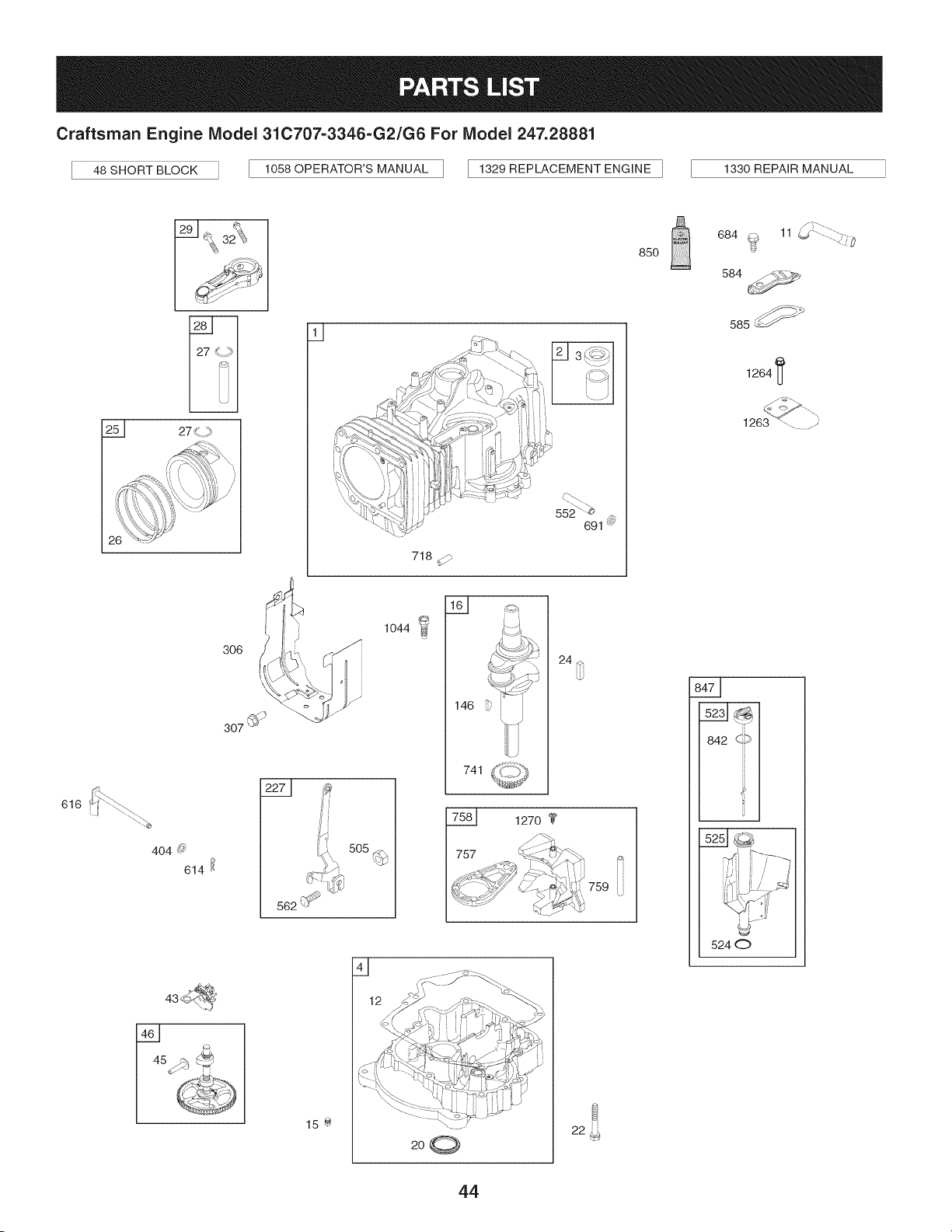
Craftsman Engine Model 31C707=3346=G2/G6 For Model 247.28881
48 SHORT BLOCK 1058 OPERATOR'S MANUAL [ 1329 REPLACEMENT ENGINE ] 1330 REPAIR MANUAL
616
129 1_ _¢\
_ 32_}_
/
25_ 27
q
ii
306 i J
,4_,
,\
307 @_
552<-_
691 @
718 d/"
_..-.(:::J
146 _'
741
24 _
1270
757
759
85O
f T"-_.
684 @ 11 _ .......:_._:@
584
585_ _
1264 I_
s__
842 c,_9
s__JG
5240
Q
15 @
44
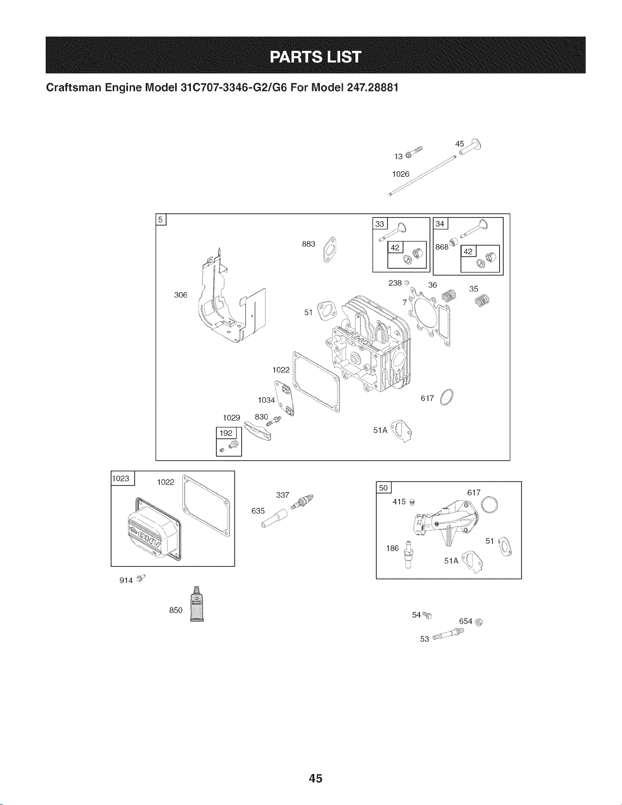
Craftsman Engine Model 31C707-3346-G2/G6 For Model 247.28881
lO26_/_
s _
883
51
238 (3 36 35
1022
1o22
337
501
617
914 ©'9
85O
54%
654 _)
53 d:*-;_::::$S'i_
45
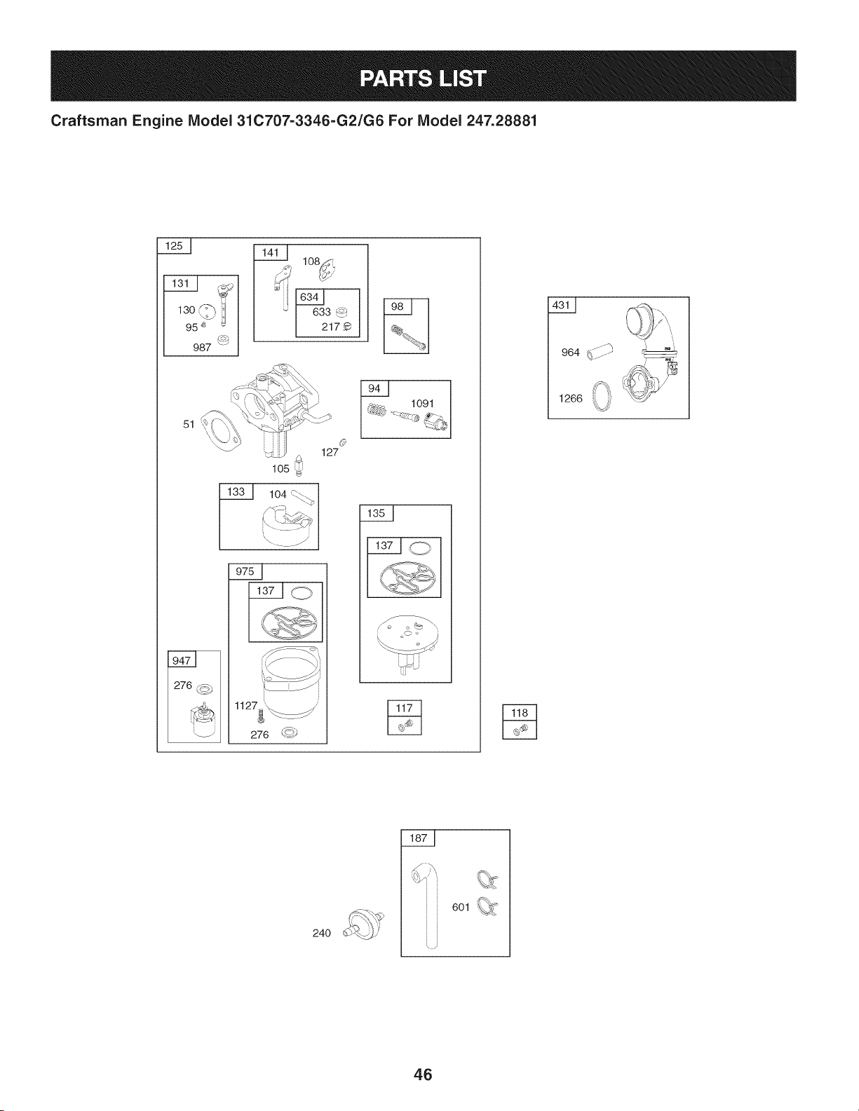
Craftsman Engine IViodel 31C707-3346-G2/G6 For IViodel 247.28881
130 :-'_
95 _ _
987
_ lO_
i
633 _
2179
51
105
Q
127
1127__
276 _)
1091
964 ........
' i
24O
6Ol _
i
46
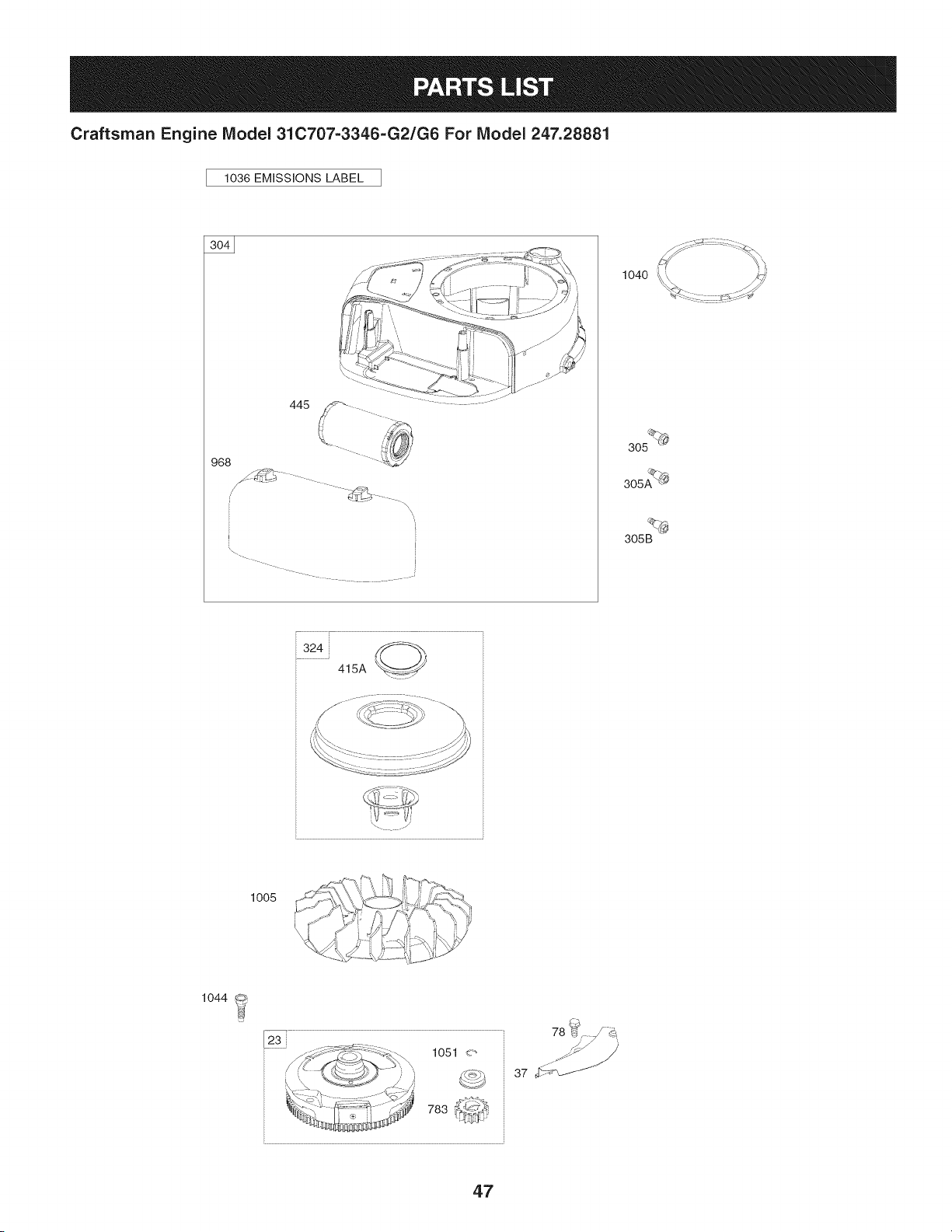
Craftsman Engine Model 310707=3346=G2/G6 For Model 247.28881
1036 EMiSSiONS LABEL
968
445
\\
I
2
1040
305 _
305AQ_
305B
324
415A
,./:,,;\ \"_{,":,_j !/ 4_7><_
lOOS C-;>..._\\d_-_t ib.j,:Q _
1044
78 b_ d_
37 _
47
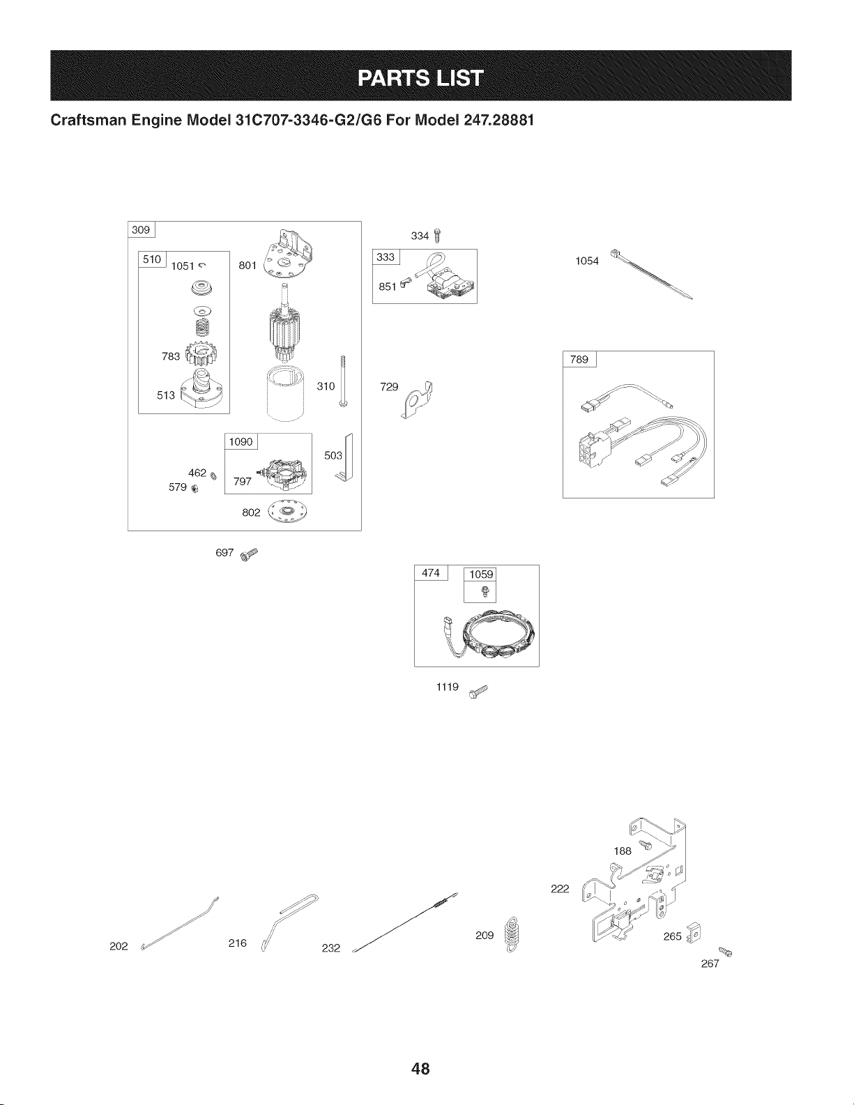
Craftsman Engine IViodel 31C707-3346-G2/G6 For IViodel 247.28881
lO51 8ol
@
783
513
462
579
. i '¸
797
802
729
334
1054
697 _
1119
188 _
202
216
232
209
222
48
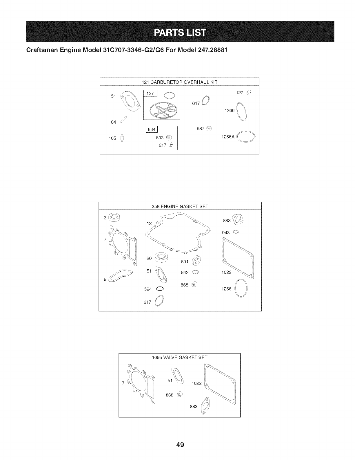
Craftsman Engine IViodel 31C707-3346-G2/G6 For IViodel 247.28881
51
104
105
121 CARBURETOR OVERHAUL KiT
O 127 _
617,, ifX,
1266 :, '_,
33 _'_
217
987_/
1266A
/';/ .>_,
3 _<J/
358 ENGINE GASKET SET
12
_i / JJ
883
943 O
2O
51
524
O
691
842 g
868 %_9
1O22
1266 ((
617
1095 VALVE GASKET SET
51
868
1o22
883
49

Craftsman Engine IViodel 31C707=3346=G2/G6 For IViodel 247.28881
Ref.
NO,
1 796010
2 399265
3 391086s
4 697106
5 796026
7 796584
11 794683
12 697110
13 793988
15 690946
16 797579
20 795387
22 692125
23 698281
24 796335
25 796172
796173
26 791936
792649
27 698469
28 796007
29 794122
32 791118
33 792868
34 791935
35 691279
36 691279
37 697352
42 499586
43 691968
45 690564
46 793880
48 697761
50 796180
51 692137
51A 796081
53 690227
54 691148
78 691693
94 793610
95 690718
98 695408
Part No. Description
CylinderAssembly
Bushing/SealKit(MagnetoSide)
Seal-Oil (MagnetoSide)
Sump-Engine
Head-Cylinder
Gasket-CylinderHead
Tube-Breather
Gasket-Crankcase
Screw(Cylinder Head)
Plug-OilDrain
Crankshaft
Seal-Oil (PTOSide)
Screw(CrankcaseCover/Sump)
Flywheel
Key-Flywheel(Steel)
PistonAssembly(Standard)
PistonAssembly(.020"Oversize)
Ring Set (Standard)
Ring Set (.020" Oversize)
Lock-PistonPin
Pin-Piston
Rod-Connecting
Screw(ConnectingRod)
Valve-Exhaust
Valve-Intake
Spring-Valve(Intake)
Spring-Valve(Exhaust)
Guard-Flywheel
Keeper-Valve
Slinger-Governor/Oil
Tappet-Valve
Gear-Cam
ShortBlock
Manifold-Intake
Gasket-Intake
Gasket-Intake
Stud (Carburetor)
Screw(IntakeManifold)
Screw(FlywheelGuard)
Kit-Nle Mixture
Screw(ThrottleValve)
Kit-Nle Speed
50
I
Ref.
I Part No,
No,
I
104 694918
105 696136
108 695419
117 843099
118 790890
121 796184
125 796109
127 690727
130 699500
131 699501
133 694914
135 698780
137 698781
141 792777
146 691639
186 794873
187 791805
188 691693
192 691986
202 691841
209 692208
216 691840
217 695409
222 694042
227 691374
232 691842
238 691843
240 394358s
265 691024
267 794904
276 695410
304 797900
305 697102
305A 793376
305B 795891
306 796006
307 691693
309 693551
Description
Pin-FloatHinge
Valve-FloatNeedle
Valve-Choke
Jet-Main(Standard)
Jet-Main(HighAltitude)
Kit-CarburetorOverhaul
Carburetor
Plug-Welch
Valve-Throttle
Kit-ThrottleShaft
Float-Carburetor
Tube-FuelTransfer
Gasket-FloatBowl
Kit-ChokeShaft
Key-Timing
Connector-Hose(intake Manifold)
Line-Fuel(Formed)(Cutto RequiredLength)
Screw(ControlBracket)
Adjuster-RockerArm
Link-MechanicalGovernor
Spring-Governor(Green)
Link-Choke
Spring-ChokeReturn
Bracket-Control
Lever-GovernorControl
Spring-GovernorLink
Cap-Valve
Filter-Fuel
Clamp-Casing
Screw(CasingClamp)
Washer-Sealing
BlowerHousing
Screw(BlowerHousing)(1/4-20x1.14)
Screw(BlowerHousing)(1/4-20x.68)
Screw(BlowerHousing)(10-16x.43)
Shield-Cylinder
Screw(CylinderShield)
Motor-Starter
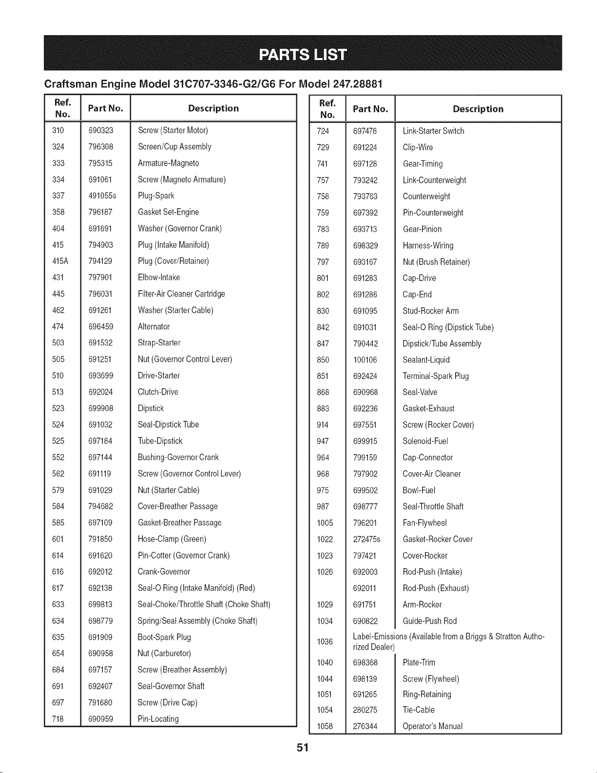
Craftsman Engine IViodel 31C707=3346=G2/G6 For IViodel
I
Ref.
I Part No.
No,
I
310 690323
324 796308
333 795315
334 691061
337 491055s
358 796187
404 691691
415 794903
415A 794129
431 797901
445 796031
462 691261
474 696459
503 691532
505 691251
510 693699
513 692024
523 699908
524 691032
525 697184
552 697144
562 691119
579 691029
584 794682
585 697109
601 791850
614 691620
616 692012
617 692138
633 699813
634 698779
635 691909
654 690958
684 697157
691 692407
697 791680
718 690959
247.28881
Description
Screw(Starter Motor)
Screen/CupAssembly
Armature-Magneto
Screw(MagnetoArmature)
Plug-Spark
GasketSet-Engine
Washer(GovernorCrank)
Plug(intakeManifold)
Plug(Cover/Retainer)
Elbow-intake
Filter-AirCleanerCartridge
Washer(StarterCable)
Alternator
Strap-Starter
Nut (GovernorControlLever)
Drive-Starter
Clutch-Drive
Dipstick
Seal-DipstickTube
Tube-Dipstick
Bushing-GovernorCrank
Screw(GovernorControlLever)
Nut (StarterCable)
Cover-BreatherPassage
Gasket-BreatherPassage
Hose-Clamp(Green)
Pin-Cotter(GovernorCrank)
Crank-Governor
Seal-O Ring(IntakeManifold)(Red)
Seal-Choke/ThrottleShaft (ChokeShaft)
Spring/SealAssembly(Choke Shaft)
Boot-SparkPlug
Nut (Carburetor)
Screw(BreatherAssembly)
Seal-GovernorShaft
Screw(DriveCap)
Pin-Locating
Ref.
No,
724
729
741
757
758
759
783
789
797
801
8O2
83O
842
847
85O
851
868
883
914
947
964
968
975
987
1005
1022
1023
1026
1029
1034
1036
1040
1044
1051
1054
1058
51
Part No. Description
697478
691224
697128
793242
793763
697392
693713
698329
693167
691283
691286
691095
691031
790442
100106
692424
690968
692236
697551
699915
799159
797902
699502
698777
796201
272475s
797421
692003
692011
691751
690822
Link-StarterSwitch
Clip-Wire
Gear-Timing
Link-Counterweight
Counterweight
Pin-Counterweight
Gear-Pinion
Harness-Wiring
Nut(Brush Retainer)
Cap-Drive
Cap-End
Stud-RockerArm
Seal-O Ring(DipstickTube)
Dipstick/TubeAssembly
Sealant-Liquid
Terminal-SparkPlug
Seal-Valve
Gasket-Exhaust
Screw(RockerCover)
Solenoid-Fuel
Cap-Connector
Cover-AirCleaner
Bowl-Fuel
Seal-ThrottleShaft
Fan-Flywheel
Gasket-RockerCover
Cover-Rocker
Rod-Push(Intake)
Rod-Push(Exhaust)
Arm-Rocker
Guide-PushRod
Label-Emissions(Availablefroma Briggs & StrattonAutho-
rized Dealer)
698368
698139
691265
280275
276344
Plate-Trim
Screw(Flywheel)
Ring-Retaining
Tie-Cable
Operator'sManual
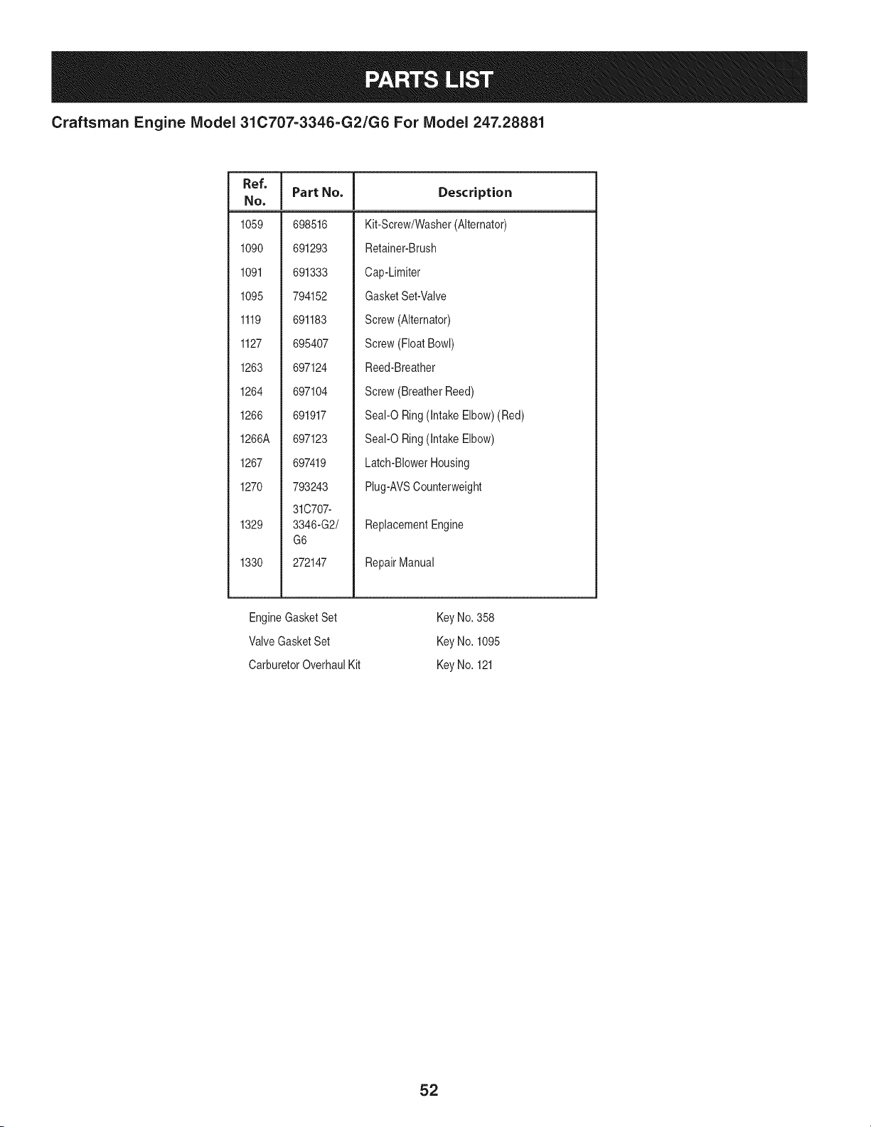
Craftsman Engine IViodel 31C707=3346=G2/G6 For IViodel 247.28881
Ref, I
NO,
1059 698516
1090 691293
1091 691333
1095 794152
1119 691183
1127 695407
1263 697124
1264 697104
1266 691917
1266A 697123
1267 697419
1270 793243
31C707-
1329 3346-G2/
G6
1330 272147
Part No. Description
Kit-Screw/Washer(Alternator)
Retainer-Brush
Cap-Limiter
GasketSet-Valve
Screw(Alternator)
Screw(FloatBowl)
Reed-Breather
Screw(BreatherReed)
Seal-O Ring(Intake Elbow)(Red)
Seal-O Ring(Intake Elbow)
Latch-BlowerHousing
Plug-AVSCounterweight
ReplacementEngine
RepairManual
EngineGasketSet
Valve GasketSet
CarburetorOverhaulKit
KeyNo. 358
KeyNo. 1095
KeyNo. 121
52
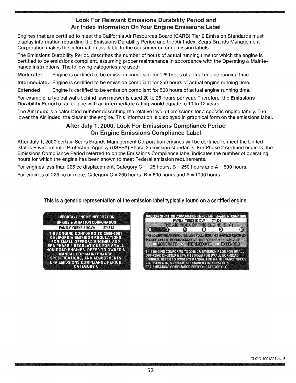
Look For Relevant Emissions Durability Period and
Air index information On Your Engine Emissions Label
Engines that are certified to meet the California Air Resources Board (CARB) Tier 2 Emission Standards must
display information regarding the Emissions Durability Period and the Air Index. Sears Brands Management
Corporation makes this information available to the consumer on our emission labels.
The Emissions Durability Period describes the number of hours of actual running time for which the engine is
certified to be emissions compliant, assuming proper maintenance in accordance with the Operating & Mainte-
nance Instructions. The following categories are used:
Moderate: Engine is certified to be emission compliant for 125 hours of actual engine running time.
Intermediate: Engine is certified to be emission compliant for 250 hours of actual engine running time.
Extended: Engine is certified to be emission compliant for 500 hours of actual engine running time.
For example, a typical walk-behind lawn mower is used 20 to 25 hours per year. Therefore, the Emissions
Durability Period of an engine with an intermediate rating would equate to 10 to 12 years.
The Air index is a calculated number describing the relative level of emissions for a specific engine family. The
lower the Air Index, the cleaner the engine. This information is displayed in graphical form on the emissions label.
After July 1,2000, Look For Emissions Compliance Period
On Engine Emissions Compliance Label
After July 1, 2000 certain Sears Brands Management Corporation engines will be certified to meet the United
States Environmental Protection Agency (USEPA) Phase 2 emission standards. For Phase 2 certified engines, the
Emissions Compliance Period referred to on the Emissions Compliance label indicates the number of operating
hours for which the engine has been shown to meet Federal emission requirements.
For engines less than 225 cc displacement, Category C = 125 hours, B = 250 hours and A = 500 hours.
For engines of 225 cc or more, Category C = 250 hours, B = 500 hours and A = 1000 hours.
This is a generic representation of the emission label typically found on a certified engine.
FAMILYYBSXS.3192VA 274812
GDOC-100182Rev.B
53
(Thispageapplicablein the U.S.A.and Canadaonly.)
Sears Brands Management Corporation (Sears), the California Air Resources Board (CARD)
and the United States Environmental Protection Agency (U.S. EPA)
Emission Control System Warranty Statement (Owner's Defect Warranty Rights and Obligations)
EMISSIONCONTROLWARRANTYCOVERAGEISAPPLICABLETOCERTI-
FIEDENGINESPURCHASEDIN CALIFORNIAIN 1995ANDTHEREAF-
TER,WHICHARE USEDINCALIFORNIA,ANDTOCERTIFIEDMODEL
California and United States Emission
The CaliforniaAir ResourcesBoard(CARD),U.S.EPAand Searsare pleased
to explainthe EmissionControlSystemWarrantyonyour modelyear2000and
latersmalloff-roadengine(SORE).In California,newsmall off-roadengines
mustbe designed,builtand equippedto meetthe State'sstringentanti-smog
standards.Elsewherein theUnitedStates, newnon-road,spark-ignition
enginescertifiedfor modelyear 1997and latermustmeetsimilarstandardsset
forth bythe U.S.EPA.Sears mustwarranttheemissioncontrol systemon your
YEAR 1997AND LATERENGINESWHICHARE PURCHASEDAND USED
ELSEWHEREIN THE UNITEDSTATES(ANDAFTERJANUARY1,2001 IN
CANADA).
Control Defects Warranty Statement
enginefor theperiodsoftime listedbelow,providedtherehas been noabuse,
neglector impropermaintenanceof your smalloff-roadengine.Youremis-
sion controlsystemincludespartssuch as thecarburetor,air cleaner,ignition
system,mufflerand catalyticconverter.Also includedmay be connectorsand
otheremissionrelatedassemblies.Wherea warrantableconditionexists,Sears
will repairyour smalloff-roadengineat no costto you includingdiagnosis,parts
and labor.
Sears Emission Control Defects Warranty Coverage
Smalloff-roadenginesarewarrantedrelativeto emissioncontrol partsdefects
fora periodof one year,subjectto provisionsset forth below.Ifany covered
Owner's Warranty
Asthe smalloff-roadengine owner,you are responsiblefor the performanceof
therequiredmaintenancelistedin yourOperatingand MaintenanceInstruc-
tions.Searsrecommendsthatyou retain all yourreceiptscoveringmaintenance
on yoursmalloff-roadengine,but Sears cannotdenywarrantysolelyfor the
lackof receiptsorfor yourfailureto ensuretheperformanceof all scheduled
maintenance.As the smalloff-roadengineowner,you shouldhoweverbe
awarethat Searsmaydenyyou warrantycoverageif your smalloff-roadengine
ora part hasfailed dueto abuse,neglect,impropermaintenanceor unap-
parton yourengineis defective,the part will be repairedorreplacedbySears.
Responsibilities
provedmodifications.Youare responsiblefor presentingyour smalloff-road
engineto an AuthorizedSearsServiceDealeras soonas a problemexists.The
undisputedwarrantyrepairsshouldbe completedina reasonableamountof
time,notto exceed30 days. Ifyou haveany questionsregardingyourwarranty
rightsand responsibilities,you shouldcontacta SearsService Representative
at 1-800-469-4663.The emissionwarrantyis a defectswarranty.Defectsare
judgedon normalengineperformance.Thewarrantyis notrelatedto an in-use
emissiontest.
Sears Emission Control Defects Warranty Provisions
ThefollowingarespecificprovisionsrelativetoyourEmissionControlDefectsWarrantyCoverage.ItisinadditiontotheSearsenginewarrantyfornon-regulated
enginesfound in theOperatingand MaintenanceInstructions.
1. WarrantedParts
Coverageunderthis warrantyextendsonly to the partslistedbelow(the
emissioncontrolsystemsparts)to the extentthese partswere presenton
the engine purchased.
a. FuelMeteringSystem
• Cold start enrichmentsystem
• Carburetorand internalparts
• FuelPump
b. Air lnduction System
• Air cleaner
• Intakemanifold
c. IgnitionSystem
• Spark plug(s)
• Magnetoignitionsystem
d. CatalystSystem
• Catalyticconverter
• Exhaustmanifold
• Air injectionsystemor pulsevalve
e. MiscellaneousItemsUsedin AboveSystems
• Vacuum,temperature,position,timesensitivevalves
andswitches
• Connectorsandassemblies
2. Lengthof Coverage
Searswarrantsto the initialownerand eachsubsequentpurchaserthat
the WarrantedParts shallbe free from defects in materialsandworkman-
shipwhich causedthe failure of the WarrantedPartsfor a periodof one
yearfrom the datethe engineis deliveredto a retailpurchaser.
3. NoCharge
Repairor replacementof anyWarrantedPartwill be performedat no
chargeto the owner,includingdiagnosticlabor whichleadsto the
determinationthata WarrantedPartis defective,if the diagnosticwork is
performedat an AuthorizedSears ServiceDealer.For emissionswarranty
servicecontact yournearestAuthorizedSears ServiceDealeras listed in
the "YellowPages"under"Engines,Gasoline,""GasolineEngines,""Lawn
Mowers,"or similar category.
4. Claimsand CoverageExclusions
Warrantyclaimsshall be filed in accordancewiththe provisionsof the
Sears EngineWarrantyPolicy.Warrantycoverageshall be excludedfor
failuresof WarrantedPartswhichare notoriginal Sears partsor because
of abuse,neglector impropermaintenanceas setforth inthe Sears
EngineWarrantyPolicy.Searsis not liableto coverfailuresof Warranted
Partscausedby the use of add-on, non-original,or modifiedparts.
5. Maintenance
Any WarrantedPart whichis notscheduledfor replacementas required
maintenanceor whichis scheduledonly for regularinspectionto the effect
of "repairor replaceas necessary"shallbe warrantedasto defectsfor the
warrantyperiod.Any WarrantedPartwhich is scheduledfor replacement
as requiredmaintenanceshallbe warrantedasto defectsonly forthe
periodof time upto the firstscheduledreplacementfor that part. Any
replacementpart that is equivalentin performanceand durabilitymay
be usedin the performanceof any maintenanceor repairs.The owneris
responsibleforthe performanceof all requiredmaintenance,as definedin
the SearsOperatingand MaintenanceInstructions.
6. ConsequentialCoverage
Coveragehereundershallextendto thefailure of any engine components
caused bythe failureof any WarrantedPartstill underwarranty.
Inthe USAandCanada,a 24 hour hot line, 1-800-469-4663,has a menu of pre-recordedmessagesofferingyou enginemaintenanceinformation.
GD0C-100188Rev.B
54
FEDERAL and/or CALIFORNIA EMISSION CONTROL WARRANTY STATEMENT
YOUR WARRANTY RIGHTS AND OBLIGATIONS
MTDConsumerGroupInc,the UnitedStatesEnvironmentalProtectionAgency (EPA),and, forthose productscertifiedfor sale in the stateof California,the
CaliforniaAir ResourcesBoard(CARB)are pleasedto explainthe emission(evaporativeand/or exhaust)controlsystem(ECS) warrantyon youroutdoor2006
andlater smalloff-roadspark-ignitedengine andequipment(outdoorequipmentengine)In California,new outdoorequipmentengines mustbe designed,built and
equippedto meetthe State'sstringentanti-smogstandards(in otherstates, 1997andlater modelyear equipmentmustbe designed,built, and equippedto meet
theU.S. EPAsmalloff-road, sparkignitionengine regulations.MTDConsumerGroupInc mustwarrantthe ECSon your outdoorequipmentenginefor the periodof
timelisted belowprovidedtherehasbeen no abuse, neglector impropermaintenanceof outdoor equipmentengine.
Your ECSmay includeparts such as the carburetor,fuel-injectionsystem,the ignitionsystem,catalyticconverter,fuel tanks,fuel lines,fuel caps, valves,canisters,
filters,vaporhoses,clamps,connectors,andotherassociatedemission-relatedcomponents.
Wherea warrantableconditionexists, MTDConsumerGroupIncwill repairyouroutdoorequipmentengine at no cost to you includingdiagnosis,parts and labor.
MAN UFACTURER'S WARRANTY COVERAGE:
Thisemissioncontrolsystemis warrantedfor two years. If any emission-relatedpart on your outdoorequipmentengine is defective,the part will berepairedor
replacedby MTDCONSUMERGROUPINC.
OWNER'S WARRANTY RESPONSIBILITIES:
Asthe outdoorequipmentengineowner,you are responsiblefor performanceof the requiredmaintenancelisted inyour owner'smanual.MTDConsumerGroup
Inc recommendsthat you retain all receiptscoveringmaintenanceon youroutdoorequipmentengine,but MTDConsumerGroupInc cannotdeny warrantysolely
forthe lackof receipts.
Asthe outdoorequipmentengineowner,you shouldhoweverbe awarethat MTDConsumerGroupInc may denyyou warrantycoverageif your outdoorequipment
engineor a part has faileddue to abuse, neglect,or impropermaintenanceor unapprovedmodifications.
Youare responsiblefor presentingyouroutdoor equipmentengineto MTDConsumerGroupInc'sdistributioncenteror servicecenteras soon asthe problem
exists.The warrantyrepairsshouldbe completedin a reasonableamountof time, not to exceed30 days. If you havea questionregardingyour warrantycoverage,
you shouldcontactthe MTDConsumerGroup IncService Departmentat 1-800-800-7310or via email at http://support.mtdproducts.com
GENERAL EMISSIONS WARRANTY COVERAGE:
MTDConsumerGroupIncwarrantsto the ultimatepurchaserand eachsubsequentpurchaserthat the outdoorequipmentengineis: Designed,built and equipped
so asto conformwith all applicableregulations;and freefrom defects in materialsand workmanshipthatcausethe failureof a warrantedpart to be identicalin all
materialrespectsto that part as describedin MTDConsumerGroup Inc'sapplicationfor certification.
The warrantyperiod beginson the date the outdoorequipmentengineis deliveredto an ultimate purchaseror first placedinto service.The warrantyperiodis two
years.
Subjectto certain conditionsand exclusionsasstated below,the warrantyon emission-relatedparts is asfollows:
1. Any warrantedpart that is not scheduledfor replacementas requiredmaintenancein the written instructionssupplied,is warrantedforthe warrantyperiod
statedabove. Ifthe part fails duringthe periodof warrantycoverage,the part will be repairedor replacedbyMTDConsumerGroupInc accordingto subsection
(4) below. Anysuch part repairedor replacedunderwarrantywillbe warrantedfor the remainderof the period.
2. Any warrantedpart that is scheduledonly for regularinspectionin the writteninstructionssupplied is warrantedforthe warrantyperiodstatedabove.Any such
part repairedor replacedunderwarrantywill be warrantedforthe remainingwarrantyperiod.
3. Any warrantedpart that is scheduledfor replacementas requiredmaintenancein thewritten instructionssuppliedis warrantedfor the periodof time beforethe
first scheduledreplacementdatefor that part. If the partfails beforethefirst scheduledreplacement,the part will berepairedor replacedby MTDConsumer
GroupInc accordingto subsection(4) below.Any such part repairedor replacedunderwarrantywill be warrantedfor the remainderof the periodpriorto the
first scheduledreplacementpointfor the part.
4. Repairor replacementof any warrantedpart underthe warrantyprovisionshereinmustbe performedat a warrantystationat no chargeto the owner.
5. Notwithstandingthe provisionsherein,warrantyservicesor repairswill beprovidedat all of our distributioncentersthatare franchisedto servicethe subject
enginesor equipment.
6. The outdoorequipmentengine ownerwill notbe chargedfor diagnostic laborthat is directlyassociatedwithdiagnosisof a defective,emission-relatedwar-
rantedpart, providedthat suchdiagnosticwork is performedat a warrantystation.
7. MTDConsumerGroupInc is liablefor damagesto otherengine or equipmentcomponentsproximatelycausedby a failure underwarrantyof any warranted
part.
8. Throughoutthe off-roadengineand equipmentwarrantyperiodstatedabove, MTDConsumerGroupInc will maintaina supplyof warrantedparts sufficientto
meetthe expecteddemandfor such parts.
9. Any replacementpart may be usedinthe performanceof any warrantymaintenanceor repairsand mustbe providedwithoutchargeto the owner.Suchusewill
notreducethe warrantyobligationsof MTDConsumerGroupInc.
10.Add-onor modifiedpartsthat are notexemptedbythe Air ResourcesBoardmay not be used.The use of any non-exemptedadd-on or modifiedparts by the
ultimatepurchaserwill begroundsfor disallowinga warrantyclaims. MTDConsumerGroup Incwill notbe liableto warrantfailuresof warrantedparts caused
bythe use of a non-exemptedadd-onor modifiedpart.
WARRANTED PARTS:
The repairor replacementof any warrantedpart otherwiseeligiblefor warrantycoveragemaybe excludedfrom such warrantycoverageif MTDConsumerGroup
Inc demonstratesthatthe outdoor equipmentenginehas beenabused,neglected,or improperlymaintained,and thatsuch abuse, neglect,or impropermainte-
nancewasthe direct causeof the needfor repairor replacementof the part.That notwithstanding,any adjustmentof a componentthat hasa factory installed,
andproperlyoperating,adjustmentlimitingdevice is still eligible for warrantycoverage. Further,the coverageunderthis warrantyextendsonly to partsthat were
presenton the off-roadengineand equipmentpurchased.
Thefollowing emissionwarrantypartsare covered(if applicable):
(1) FuelMeteringSystem
• Cold start enrichmentsystem(softchoke)
• Carburetorand internalparts (or fuel injectionsystem)
• Fuelpump
• Fueltank
(2) Air InductionSystem
• Air cleaner
• Intakemanifold
(3) IgnitionSystem
• Spark plug(s)
• Magneto ignitionsystem
(4) ExhaustSystem
• Catalyticconverter
• SAI (Reed valve)
(5) MiscellaneousItemsUsedin AboveSystem
• Vacuum,temperature,position,timesensitivevalvesand switches
• Connectorsandassemblies
(6) EvaporativeControl
• Fuelhose
• Fuelhoseclamps
• Tetheredfuel cap
• Carboncanister
• Vapor lines
GDOC-100223Rev.A
Congratulationson makinga smartpurchase.YournewCraftsman@
productis designedand manufacturedfor yearsof dependableopera-
tion.But likeall products,it mayrequirerepairfromtimeto time.That's
whenhavinga RepairProtectionAgreementcansaveyoumoneyand
aggravation.
Here'swhatthe RepairProtectionAgreement*includes:
* Expert service byour 10,000professionalrepairspecialists
o Unlimitedserviceand no chargefor partsand laboron all
coveredrepairs
o Product replacementup to $1500if yourcoveredproductcan't be
fixed
• Discountof 10%from regularprice of serviceand relatedinstalled
partsnotcoveredby theagreement;also, 10%off regularpriceof
preventivemaintenancecheck
• Fast help by phone- we call it RapidResolution- phone support
froma Searsrepresentative.Thinkof usas a "talkingowner's
manual."
Onceyou purchasethe Agreement,a simplephonecall is all thatit
takesfor youto scheduleservice.Youcan call anytimedayor night,or
schedulea serviceappointmentonline.
The RepairProtectionAgreementis a risk-freepurchase.If youcancel
for any reasonduringthe productwarrantyperiod,wewill provideafull
refund.Or,a proratedrefundanytimeafter the productwarrantyperiod
expires.Purchaseyour RepairProtectionAgreementtoday!
Somelimitationsand exclusionsapply. For pricesand additional
informationin the U.S.A. call 1-800-827-6655.
*Coverage in Canadavaries on some items. Forfull details call
Sears Canadaat 1-800-361-6665.
Sears Installation Service
ForSearsprofessionalinstallationof homeappliances,garagedoor
openers,waterheaters,and othermajorhomeitems,in the U.S.A.or
Canadacall 1-800-4-MY-HOME®.
57
Operaci6n segura Practicas .......... Paginas 59 Fuera de temporada de almacenamiento Paginas 84
Etiquetas De Seguridad .............. Paginas 64 Solucion de problemas .............. Paginas 85
Asamblea ......................... Paginas 66 Lista de piezas ..................... Paginas 30
Operacion de ...................... Paginas 68 Reparaci6n de Acuerdo de Proteccion .. Paginas 91
De Servicio y Mantenimiento de ....... Paginas 75 Servicio de nOmeros .......... atrasados Paginas
ARTESANO DE DOS AI_IOS DE GARANTiA
PORDOSAnOSa partir dela fechade compra,si alguna partenofungiblesde esteequipode equitaci6nfalladebidoa un defectode material
o manode obra,www.craftsman.corn visiteo Ilamea 1-800-659-5917para organizarde formagratuitaen reparaci6nde viviendas.
Elmarcoy eleje delanterose reparar_deformagratuitadurantecincoa_osa partirdela fechade comprapor defectosen materialo manode
obra.
Entodos loscasos,si la reparaci6nresultaimposible,el equipode montara caballoserAsustituidode forma gratuitaconel mismoo equiva-
lente.
Labateriase sustituyede formagratuitadurante90 diasa partirdela fechade comprapordefectosenmaterialomanode obra (nuestras
pruebasdemuestraqueno mantienela carga).
Estagarantiaes inv_lidasi este productose utilizaal mismotiempo la prestaci6nde servicioscomercialeso si se alquilaa otrapersona.
Estagarantia cubrelosdefectosSOLOde materiales y fabricaci6n. La garantiano incluye:
* Aquellaspiezasfungiblesquepuedengastarsepor el uso normaldentrodel periodode garantia,incluyendoperono limitadoa, cuchillas,
bujias,filtrosde aire, correasy filtrosde aceite.
* Losserviciosde mantenimiento,cambiosde aceite,o puestasa punto.
* Tireel reemplazoo reparaci6nde pinchazoscausadospot objetosexternos,tales comoclavos,espinas,toconesovidrio.
* Tirede la ruedao el reemplazoo la reparaci6nresultantesdel desgastenormal,accidenteo realfuncionamientoo mantenimiento.
. Las reparacionesnecesariasdebidoal abusodeloperador,incluyendopero no limitadoa los da_oscausadosporel remolquede los
objetosm_sall_ dela capacidaddel equipode equitaci6n,el impactode objetosquedoblen la estructurao el cig(Je_al,ode excesode
velocidaddel motor.
. Las reparacionesnecesariasdebidoa la negligenciadel operador,incluyendoperono limitadoa, da_osel_ctricosy mec_nicoscausados
porunalmacenamientoinadecuado,no utilizaci6nde la calidado cantidadde aceitede motor,no mantenerel piso librede residuos
infiamables,o faltademantenimientodelEquipoecuestredeacuerdoa lasinstruccionescontenidasen el manualdel operador.
. Elmotor (sistemade combustible)de limpiezao reparacionesprovocadasporuncombustiblequese contaminadou oxidado(viejo).En
general,elcombustibledebeser utilizadodentrodelos 30 dias siguientesa la fechadecompra.
. Deterioroy desgastenormalde los acabadosexteriores,o reemplazode la etiquetadelproducto.
Estagarantiale otorgaderechoslegalesespecificos,y ustedtambi_npuedetenerotrosderechosque variandeestadoa estado.
Sears Brands Corporation Gesti6n, Hoffman Estates, iL60179
Aceitedel motor: SAE30
Combustible: Gasolinasinplomo
Bujia: Champion®RC12YC
Motor: Briggs& StrattonI/C®
N_mero de modelo ..........................................................
N_mero de serie ..............................................................
Fechade compra .............................................................
Registrearribael nOmerodel modelo,el nOmerode seriey la fecha
de compra
© Sears Brands,LLC
58
Lapresenciadeeste sirnboloindicaque setratade instrucciones
irnportantesde seguridadquese deben respetarpara evitar
poneren peligrosu seguridadpersonaly/o materialy lade otras
personas.Lea y siga todaslas instruccionesdeestemanualantes
de poneren funcionarnientoesta rn_.quina.Si no respetaestas
instruccionespodriaprovocarlesionespersonales.Cuandoveaeste
sirnbolo,ipresteatenci6na la advertencia!
PROPOSICION 65 DE CALIFORNIA
Elescapedel motordeeste producto,algunosde suscornponentes
y algunoscornponentesdelvehiculocontieneno liberansustancias
quirnicasqueel estado de Californiaconsideraque puedenproducir
c_.ncer,defectosde nacirnientouotros problernasreproductivos.
Losbornesdela bateriay los accesoriosalinescontienenplornoy
cornpuestosde plorno,sustanciasquirnicasque segOnIo estableci-
do pot el Estadode Californiacausanc_.ncery da_osen el sisterna
reproductivo.Ldveselas manos despu_sde estar en contacto
con estoscomponentes.
Estarn_.quinarueconstruidaparaseroperadade acuerdocon
las reglasde seguridadcontenidasen este manual.AI igualque
concualquiertipo deequipornotorizado,undescuidoo errorpor
partedel operadorpuedeproducirlesionesgraves.Esta rn_.quina
es capazde arnputarrnanosy piesy dearrojarobjetoscon gran
fuerza.Deno respetarlas instruccionesde seguridadsiguientesse
puedenproducirlesionesgraveso la rnuerte.
Su responsabilidad--Restrinja el usode esta rn_.quina
rnotorizadaalas personasque lean,cornprendany respetenlas
advertenciase instruccionesque aparecenen este manualyen la
rn_.quina.
iGUARDEESTASINSTRUCCIONES!
FUNCIONAIVIIENTO GENERAL
• Lea,entienday curnplatodas las instruccionesincluidasen
la rn_.quinayen los rnanualesantesde rnontarlay utilizarla.
Guardeestemanualen un lugarseguroparaconsultasfuturasy
peri6dicas,asi cornoparasolicitarrepuestos.
• Farniliaricesecontodoslos controlesy con el usoadecuado
delos rnisrnos.Sepa c6rnodetenerlarn_.quinay desactivarlos
controlesr_.pidarnente.
• No perrnitanuncaque los ni_osrnenoresde 14a_osutilicen
estarn_.quina.Los ni_osde 14a_osen adelantedebenleer y
entenderlas instruccionesde operaci6ny norrnasdeseguridad
contenidaseneste manual,y en la rn_.quinay debenser
entrenadosy supervisadospor unadulto.
• Nuncaperrnitaquelos adultosoperenesta rn_.quinasin recibir
antesla instrucci6napropiada.
• Paraayudara evitar el contactocon las cuchillaso una lesi6npor
algOnobjetoque sea arrojado,rnantengaa los observadores,a
los ayudantes,ni_osy rnascotasalejadosal rnenos25 metrosde
la rn_.quinarnientrasest,. en funcionarniento.Detengala rn_.quina
si alguienentraen la zona.
• Inspeccionerninuciosarnenteel Areadondeutilizar_,el equipo.
Retiretodaslas piedras,palos,cables,huesos,juguetesy otros
objetosextra_osque podrianser recogidosy arrojadospor la
acci6nde las cuchillas.Losobjetosarrojadospor la rn_.quina
puedenproducirlesionesgraves.
• Planifiqueel patr6ndecortedelc_spedque hade seguirpara
evitarla descargade materialhacialoscarninos,las veredas,los
observadores,etc.Eviteadern_.sdescargarmaterialcontralas
paredesy obstruccionesque podrianprovocarque el material
descargadorebotecontrael operador.
• Paraprotegerselos ojos utilicesiernpreanteojoso antiparras
deseguridadrnientrasoperala rn_.quinao rnientraslaajusta
o repara.Losobjetosarrojadosque rebotanpuedenproducir
lesionesocularesgraves.
• Utilicezapatosde trabajoresistentes,de suelafuerte,asi corno
pantalonesy carnisasajustados.Las prendassueltaso las
alhajaspuedenquedaratrapadasen las piezasrnovibles.Nunca
operela rn_.quinadescalzoo con sandalias.
• Est_atentoa lacortadoray a la direcci6nde la descargade
losaditarnentosy noapuntea nadie.Nuncaopere la cortadora
de c_spedsin que est_nen su lugarapropiadolacubiertade
descargao elcolectorde recortesde cesped.
• Noponga lasrnanoso lospies cercade las piezasrotatoriaso
debajode la plataforrnadecorte. Elcontactocon las cuchillas
puedeproducirla arnputaci6nde rnanosy pies.
• Unacubiertade descargafaltanteo da_adapuedeprovocarel
contactocon la cuchillao lesionespor objetosarrojados.
• Detengala(s)cuchilla(s)cuandoatraviesesenderos,sendaso
carninosdegravay cuandono est_cortandoel cesped.
• Vigileel tr_.nsitovehicularcuandoest_operandocercade o en
crucesde carninos.Estarn_.quinano debeutilizarseen la via
pOblica.
• Noopereestarn_.quinabajolosefectosdel alcoholo de drogas.
• Corteel cespedsolarnentecon luzdedia o con unabuenaluz
artificial.
• Nuncatransportepasajeros.
• Desenganchela(s)cuchilla(s)antesdecolocarlarnarchaatr_.s.
Retrocedalentarnente.Siernpremirehaciaabajoy haciaatr_.santes
y rnientrasretrocede,paraevitaraccidentes.
• Reduzcalavelocidadantesdedarlavuelta.Operela rn_.quina
suavernente.Evitelaoperaci6nerr_.ticay lavelocidadexcesiva.
• Desenganchela(s)cuchilla(s),coloqueel frenode estaciona-
rniento,detengael motory esperehastaque la(s)cuchilla(s)se
detenga(n)porcornpletoantesderetirarelcolectordec_sped,
vaciarlos recortes,destaparel canal,retirarrestosde cespedo
desechos,o hacercualquierajuste.
59
• Nuncadejelarn_.quinaen funcionarnientosinvigilancia.Apague
siernprelascuchillas,coloqueelfrenode rnano,detengael motory
retirela Ilaveantesdebajarsedelvehiculo.
• Tengasurnocuidadoal cargaro descargarla rn_.quinaen un
rernolqueocarni6n.Estaunidadnodebeconducirseenascensoo
descensoderarnpas,porquepodrialadearsey provocarlesiones
personalesgraves.Enlas rarnpaslarn_.quinasedebeernpujar
rnanualrnenteparacargarlao descargarlacorrectarnente.
• Elsilenciadory el motorse calientany puedencausarquernaduras.
Nolos toque.
• Reviseel espaciolibrepot encirnade lacabezaantesdeconducir
bajolas rarnasbajasde_.rboles,cables,cerrarnientosdepuertas,
etc.en loscualeseloperadorpodriaatorarseo serernpujadofuera
dela rn_.quina,Ioque podriaresultaren lesionesgraves.
• Desenganchetodoslosernbraguesde los accesoriosy presione
totalrnenteel pedaldel frenoantesde intentararrancarel motor.
• Larn_.quinaest,.diseSadaparacortarc_spedresidencialnormal,
conuna alturano mayora 10".Nointentecortarcespeddernasiado
crecido,seco(porej.,pastura)nipilasde hojassecas.El c_sped
y las hojassecaspuedenentraren contactoconel escapedel
motory/o acurnularseenla plataforrnade lacortadorade cesped,
convirti_ndoseen unpeligrodeincendio
• Utilicesolarnenteaccesoriosy aditarnentosaprobadosparaesta
rn_.quinapot elfabricantedela misrna.Lea,cornprenday siga
todaslas instruccionesproporcionadasconlosaccesorioso
aditarnentosaprobados.Paraobteneruna listade losaccesorios
aprobadosy losarchivosadjuntos,Ilarne1-800-659-5917.
• Losdatosestadfsticosrnuestranquelosoperadoresde60 aSos
y rnayoresseven involucradosenunaltoporcentajedelesiones
relacionadascontractorescorta cesped.Estosoperadoresdeben
evaluarsu capacidadparaoperarel tractorcortac_speden forrna
suficienternentesegurapara protegersea ellosrnisrnosy a los
dern_.scontralesionesgraves.
Si se presentansituacionesque no est_.nprevistasen este
manualseacuidadosoy use el sentidocornQn.Contacto1-800-
659-5917parainforrnaci6ny asistencia.
FUNCIONAiVIIENTO EN PENDIENTES
Las pendientesson unfactorirnportanterelacionadoconaccidentes
porderrapey vuelcosquepuedenproducirlesionesgravese incluso
la rnuerte.Laoperaci6nen pendientesrequieremayorprecauci6n.
Si nopuederetrocederen la pendienteo si no se sienteseguro,no
realiceningunaoperaci6nde corte.
Parasu seguridad,use el indicadordependientesque se incluye
cornopartede este manualpara rnedirla pendienteantes de operarla
rn_.quinaen una zonainclinada.Sila pendientees mayorde 15 grados
segQnel rnedidor,no opereesta rn_.quinaenese sector,puespodria
causarlesionesgraves.
HagaIo siguiente:
• Podehaciaarribay abajode las pendientes,no de forrnatrans-
versal.Tengacuidadocuandocarnbiededirecci6nal operaren
pendiente.
• Est_atentoa loshoyos,surcos,baches,rocas,uotrosobjetos
ocultos.Elterrenodesniveladopuedevoltearla rn_.quina.Elcesped
altopuedeocultarobst_.culos.
• Vayaa bajavelocidad.ElijaunavelocidadIosuficienternentebaja,
de rnodoquenotengaque detenerseo hacercarnbiosrnientras
est,.sobrela pendiente.Losneurn_.ticospodrianperdertracci6n
sobrelaspendientesa[3ncuandolosfrenosfuncionaranapro-
piadarnente.Siernprernantengala rn_.quinaencarnbiornientras
desciendelaspendientes,parapoderfrenarconel motor.
• Sigalas recornendacionesdel fabricanteparalos pesoso contra-
pesosdelas ruedas,pararnejorarlaestabilidaddelarn_.quina.
Pararecornendaciones,Ilarneal 1-800-659-5917.
• Tengaespecialcuidadocon loscolectoresde c_spedu otros
aditarnentos.Losrnisrnospuedenrnodificarla estabilidadde la
rn_.quina.
• Hagaquetodoslosrnovirnientosen laspendientesseanlentosy
graduales.Nocarnbierepentinarnentela velocidadni la direcci6n.
Unfrenadoo carnbiode velocidadrepentinospuedencausarque
el frentede larn_.quinase levantey d_unavolteretahaciaatr_.s,Io
quepodriaproducirlesionesgraves.
• Evitearrancaro detenerseenunapendiente.Silosneurn_.ticos
pierdenlatracci6n,desenganchelascuchillasy descienda
lentarnentela pendiente.
No hagaIo siguiente:
• Nogiresobrelaspendientesa rnenosqueseanecesario.Sies
posible,girelentarnentey gradualrnenteduranteeldescenso.
• Nocorteel c_spedcercade pozos,hundirnientoso terraplenes.La
cortadoradec_spedpuedevolcarserepentinarnentesiunade las
ruedasest,.sobreel hordedeunacantilado,zanjao siunhordese
desrnorona.
• Nointenteestabilizarlarn_.quinaponiendoel pie enel suelo.
• Noutiliceuncolectordec_speden pendientesernpinadas.
• Nopodeel c_spedhQrnedo.Unarnenortracci6npodriacausar
derrapes.
• Noparadescender.Elexcesodevelocidadpuedehacerqueel
operadorpierdaelcontroldelarn_.quina,ocasionandolesiones
graveseinclusolarnuerte.
• Norernolquecargaspesadasdetr_.sdelosaditarnentos(carritode
basuracargado,podadoraderodillos,etc)en pendientesrnayores
de5 grados.Cuandosedesplazapendienteabajo,el pesoadicional
tiendeaernpujareltractory puedehacerquese pierdael control
delrnisrno(porejernplo,el tractorsepuedeacelerar,se reducela
capacidadparafrenary rnaniobrar,losaccesoriospuedenplegarse
cornouncortaplurnasy hacerqueel tractorvuelque).
NINOS
Puedenocurriraccidentestr_.gicossi el operadornoest,.atentoa la
presenciade niSos.PotIo general,los niSosse sientenatraidospor
estetipo de rn_.quinasy su funcionarniento.Noentiendenlos riesgos
ni los peligros.Nuncaasurnaque los niSosperrnanecer_.nen el rnisrno
lugardonde losvio por Qltirnavez.
• Mantengaa losniSosfueradel_.readetrabajoy bajoestricta
vigilanciadeunadultoresponsableadern_.sdelpropiooperador.
Est_alertay apaguela rn_.quinasi unniSoingresaal_.rea.
• Antesy rnientrasest,. retrocediendo,mirehaciaatr_.sy cuidequeno
hayaniSos.
NuncatransporteniSos,aQnconlacuchillaapagada.Podriancaerse
y resultarseverarnenteheridoso interferirconlaoperaci6nsegurade
la rn_.quina.
Tengaextrernaprecauci6ncuandoseaproxirneaesquinasciegas,
portales,arbustos,_.rbolesuotrosobjetosquepuedanirnpedirlever
a unniSoquesecruceenel recorridode larn_.quina.
6O
• ParaevitaraccidentesaloperarenrnarchaatrAs,siernpredesengan-
chelascuchillasantesde colocarrnarchaatrAs.Siest_instalado,
el"ModoPrecaucidnMarchaAtr_s"(hojasde operarla rn_quina,
rnientrasquelospaseosa la inversa)no debeutilizarsecuandohay
ni_osuotraspersonaspresentes.
• Mantengaa losni_osalejadosdelosrnotoresen rnarchao calientes.
Puedensufrirquernadurasconunsilenciadorcaliente.
• RetirelaIlavecuandodeje la rn_.quinasinvigilancia,evitequeuna
personasinautorizaci6nla rnaneje.
No perrnitanuncaque los ni_osrnenoresde 14a_osutilicenesta
rn_quina.Losni_osde 14a_osen adelantedebenleer y entenderlas
instruccionesdeoperaci6ny norrnasde seguridadcontenidasen este
manual,yen la rn_quinay debenserentrenadosy supervisadospor
unadulto.
REIVIOLQUE
• RernolqueL_nicarnenteconunarn_quinaquecuenteconun
enganchediseSadopararernolcar.Noacopleequiporernolcado
exceptoen el puntode enganche.
• SigalasrecornendacionesdelfabricanteenIoque respectaalos
lirnitesdepesodelosequiposa rernolcary al rernolqueen pendien-
tes.Pararecornendaciones,Ilarneal 1-800-659-5917.
• Nuncaperrnitala presenciade niSosuotraspersonasdentroosobre
losequiposrernolcados.
• Enlaspendientes,elpesodelequiporernolcadopuedecausar
p_rdidadetraccidny perdidade controlde larn&quina.
• Siernpreuseextralaprecauci6nrernolcandoconunarnaquina
capazdehacervueltasapretadas(p.ejpaseo"devueltacero"- en el
cortacesped).Hagaarnpliasvueltasparaevitaralgato-knifing.
• Desplaceselentarnentey dejedistanciaadicionalparafrenado.
• Noparadescender.
SERVIClO
Manejo seguro de la gasolina
Paraevitarlesionespersonaleso daSosrnaterialessea surnarnente
cuidadosoal rnanipularla gasolina.Lagasolinaes surnarnente
inflarnabley sus vaporespuedencausarexplosiones.Se puede
lesionargravernentesi derrarnagasolinasobreustedo sobrela ropa,
ya que _sta se puedeincendiar.L&vesela piely c&rnbiesede ropade
inrnediato.
• Utilices61olosrecipientesparagasolinaautorizados.
• NuncaIlenelos recipientesenel interiorde unvehiculoo carni6n
o cajade rernolquecon recubrirnientopl&stico.Coloquesiernpre
losrecipientesenel piso y lejosdel vehiculoantesde realizarla
carga.
• Cuandoseafactible,retireel equipoa gasolinadel carni6no
rernolquey II_neloen elsuelo.Si esto no es posible,Ileneel
equipoen unrernolqueconun contenedorport&til,envezde
hacerlocon una boquilladispensadorade gasolina.
• Mantengala boquillade Ilenadoencontactoconel horde del
dep6sitode combustibleocon la aberturadel recipienteen todo
rnornento,hastaterrninarlacarga. 1/outiliceundispositivode
boquilladeapertura/cierre.
• Apaguetodosloscigarrillos,cigarros,pipasy otrasfuentesde
cornbusti6n.
• Nuncacarguecombustibleen la rn&quinaenun espaciocerrado.
• Nuncasaquela tapadel cornbustibleniagreguecombustible
rnientrasel motorest&calienteo enrnarcha.Dejequeel motor
seenfrie porIornenosdos rninutosantesde volvera cargar
combustible.
• Nuncalleneen excesoel dep6sitode combustible.Lleneel
tanqueno rn&sde 1/2pulgadapordebajode la basedel cuello
del tap6nde carga, paradejar espacioparalaexpansi6ndel
combustible.
• Vuelvaa colocarlatapa dela gasolinay ajL_stelabien.
• Lirnpieel combustiblequese hayaderrarnadosobreel motory el
equipo.Trasladelarn&quinaa otrazona.Espere5 rninutosantes
de encenderel motor.
• Parareducirel riesgode incendio,rnantengala rn&quinalirnpia
de pasto,hojasy de acurnulaci6nde otros residuos.Lirnpielos
derrarnesdeaceiteo combustibley saquetodoslosresiduos
ernbebidosde combustible.
• Nuncaguardelarn&quinao el recipientedecombustibleen un
espaciocerradodondehayafuego,chispaso luz piloto,corno
porejernplodecalentadoresdeagua,calefactoresde arnbientes,
hornos,secadoresde ropau otrosaparatosa gas.
• Dejeque larn&quinase enfriecincorninutospor Iornenosantes
de guardarla.
Servicio general
• Nuncaenciendael motoren espacioscerradosoen unazona
con pocaventilaci6n.El escapedel motorcontienernon6xidode
carbono,ungas inodoroy letal.
• Antesdelirnpiar,repararo inspeccionarla rn&quina,cornpruebe
que la(s)cuchilla(s)y todaslaspartesenrnovirnientose hayan
detenido.Desconecteel cablede la bujfay p6ngalohaciendo
rnasacontrael motorparaevitarque se enciendaaccidental-
rnente.
• Reviseperi6dicarnenteparaasegurarsequelascuchillasse
detenganpor cornpletoen aproxirnadarnentecinco(5) segundos
despu_sdeaccionarel controlde desenganchede la(s)
cuchilla(s).Si las cuchillasno se detienendentrodeeste lapso
de tiernpo,su unidaddeber&ser reparadapor su distribuidorde
servicioautorizadoMTD.
• Reviseconfrecuenciael funcionarnientodelsisternadefrenos
ya que est,. sujetoa desgasteporla operaci6nnormal.Ajuste y
efectL_ernantenirnientosegL_nse requiera.
61
• Reviselos pernosdemontajedela(s) cuchilla(s)y del motora
intervalosfrecuentesparaverificarqueest_nbienapretados.
Adem_.s,inspeccionevisualmentela(s) cuchilla(s)en buscade
daSos(porejemplo,desgasteexcesivo,abolladuras,rajaduras,
etc.). Reemplacela(s)cuchilla(s)Qnicamentecon lascuchillas
defabricantesde equiposoriginales(O.E.M.)listadasen este
manual.Elusode piezasqueno cumplencon las especifi-
cacionesdelequipooriginal podriatenercomoresultadoun
rendimientoincorrectoy adem_.sponeren riesgola seguridad.
• Lascuchillasdelas podadorassonmuyafiladas.Envuelvala
cuchillao utiliceguantesy extremelasprecaucionescuando
efectQemantenimiento.
Mantengatodoslos pernos,tuercasy tornillosbienajustados
paraasegurarsede quela m_.quinase encuentraen condiciones
segurasde operaci6n.
• Nuncaaltereel sistemade enclavamientode seguridadni
otrosmecanismosde seguridad.Controleperi6dicamenteque
funcionencorrectamente.
Despu_sdegolpearcon algQnobjetoextraSo,detengael motor,
desconecteelcablede la bujfay conecteel motora masa.
Inspeccioneminuciosamentela m_.quinaparaver si est,. daSada.
Repareel daSoantesdearrancary ufilizarla m_.quina.
Nuncatratede hacerajusteso reparacionesa la m&quina
mientrasel motorest&enmarcha.
• Loscomponentesdel colectorde c_spedy la cubiertade
descarga,estansujetosa desgastey daSosque podriandejar
expuestaspartesen movimientoo permifirque se arrojenobjetos.
Paraprotegersuseguridad,verifiquefrecuentementetodoslos
componentesy reempl_.celosinmediatamentes61ocon piezasde
los fabricantesdel equipooriginal,listadosen este manual.El uso
de piezasque nocumplencon las especificacionesdel equipo
originalpodriatenercomo resultadoun rendimientoincorrectoy
adem_.sponeren riesgola seguridad.
• Nocambielaconfiguraci6ndel reguladordel motorni Ioopere
a sobrevelocidad.El reguladordel motorcontrolala velocidad
m_.ximasegurade funcionamientodel motor.
• Mantengao reemplacelasefiquetasde seguridade instrucciones
segQnseanecesario.
Respetelas normasreferentesa ladisposici6ncorrectay las
reglamentacionessobregasolina,aceite,etc. paraprotegerel
medicambiente.
• SegQnla Comisi6ndeSeguridadde Productospara el Consu-
midorde los EstadosUnidos(CPSC)y laAgenciade Protecci6n
Ambientalde los EstadosUnidos(EPA),este productotieneuna
vida Qtilmediade siete(7)aSos,6 270 horasdefuncionamiento.
AIfinalizarla vidaOtilmedia,adquierauna m_.quinanuevao haga
inspeccionaranualmente_staSearspor uno u otrodistribuidorde
serviciosparacerciorarsedeque todos los sistemasmec_.nicos
y de seguridadfuncionancorrectamentey no tienenexcesivo
desgaste.Si noIo hace,puedenproducirseaccidentes,lesiones
o muerte.
NO MODIFIQUE EL MOTOR
Paraevitarlesionesgraveso lamuerte,nomodifiqueel motorbajo
ningunacircunstancia.Si cambialaconfiguraci6ndel reguladordel
motorel motorpuededescontrolarsey operara velocidadesinsegu-
ras.Nuncacambielaconfiguraci6ndef_.bricadel reguladordel motor.
AVlSO REFERIDO A EMISIONES
Losmotoresque est_.ncertificadosy cumplencon las regulaciones
de emisionesfederalesEPAy de CaliforniaparaSORE(Equipos
peque_ostodoterreno)est_.ncertificadosparaoperar congasolina
comQnsin plomoy puedenincluirlos siguientessistemasde control
de emisiones:Modificaci6nde motor(EM) y catalizadorde tresvias
(TWO)siest_.nequipadosde esa manera.
GUARDACHISPAS
EstamAquinaest,.equipadacon un motorde combusti6ninternay
nodebe ser utilizadaen o cercade unterrenoagrestecubiertopor
bosque,malezaso hierbaexceptosi el sistemade escapedel motor
est,.equipadocon unamortiguadordechispasquecumplacon las
leyeslocaleso estatalescorrespondientes,en caso de haberlas.
Si se utiliza un amortiguadorde chispasel operadorIo debemantener
en condicionesde usoadecuadas.Enel Estadode California las
medidasanteriormentemencionadassonexigidasporIcy (Arficulo
4442del C6digode RecursosPOblicosde California).Esposible
queexistanleyessimilaresenotros estados.Lasleyesfederalesse
aplicanen territoriosfederales.
Puedeconseguirelamortiguadordechispasparael silenciadora
travesde su distribuidorautorizadode motoreso poni_ndoseen
contactoconel centrode servicioSears.
62
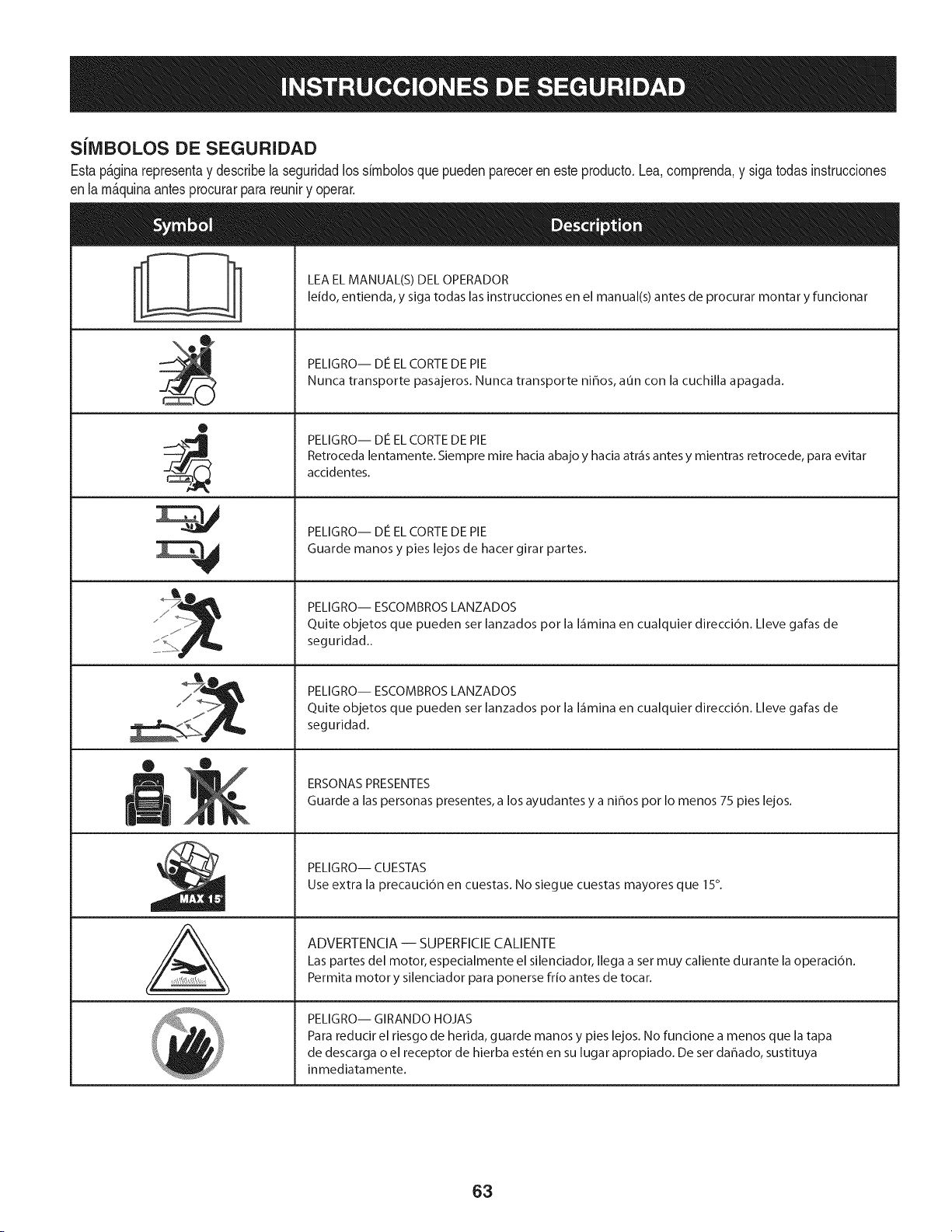
SJlVlBOLOS DE SEGURIDAD
Estap&ginarepresentay describelaseguridadlos simbolosquepuedenpareceren esteproducto.Lea,comprenda,y sigatodas instrucciones
enla m_quinaantesprocurarpara reuniry operar.
0
AL
LEA EL MANUAL(S) DEL OPERADOR
leido, entienda, y siga todas las instrucciones en el manual(s) antes de procurar montar y funcionar
PELIGRO-- DE EL CORTE DE PIE
Nunca transporte pasajeros. Nunca transporte ni_os, aun con la cuchilla apagada.
PELIGRO-- DE EL CORTE DE PIE
Retroceda lentamente. Siempre mire hacia abajo y hacia atr_is antes y mientras retrocede, para evitar
accidentes.
PELIGRO-- DE EL CORTE DE PIE
Guarde manos y pies lejos de hacer girar partes.
PELIGRO-- ESCOMBROS LANZADOS
Quite objetos que pueden set lanzados pot la I_imina en cualquier direcci6n. Lleve galas de
seguridad..
PELIGRO-- ESCOMBROS LANZADOS
Quite objetos que pueden set lanzados pot la I_imina en cualquier direcci6n. Lleve galas de
seguridad.
ERSONAS PRESENTES
Guarde alas personas presentes, a los ayudantes y a ni_os pot Io menos 75 pies lejos.
PELIGRO-- CUESTAS
Use extra la precauci6n en cuestas. No siegue cuestas mayores que 15°.
ADVERTENCIA -- SUPERFICIE CALIENTE
Las partes del motor, especialmente el silenciador, Ilega a set muy caliente durante la operaci6n.
Permita motor y silenciador para ponerse frio antes de tocar.
PELIGRO-- GIRANDO HOJAS
Para reducir el riesgo de herida, guarde manos y pies lejos. No funcione a menos que la tapa
de descarga o el receptor de hierba est_n en su lugar apropiado. De ser dahado, sustituya
inmediatamente.
63
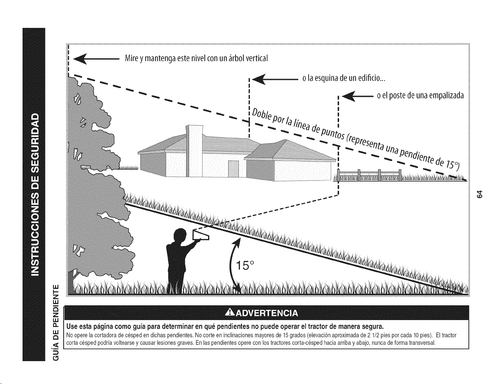
_- Mireymantengaestehive[conunJrbo[vertical
Z
IJJ
o [aesqu[nadeunedifido...
15 °
Use esta pagina como guia para determinar en qu_ pendientes no puede operar el tractor de manera segura.
Noopere la cortadorade cespeden dichaspendientes.Nocorteen inclinacionesmayoresde 15grados(elevaci6naproximadade 2 1/2 piesporcada 10 pies). El tractor
cortacespedpodriavoltearsey causarlesionesgraves.Enlas pendientesoperecon los tractorescorta-cespedhaciaarribay abajo,nuncade formatransversal.
£5
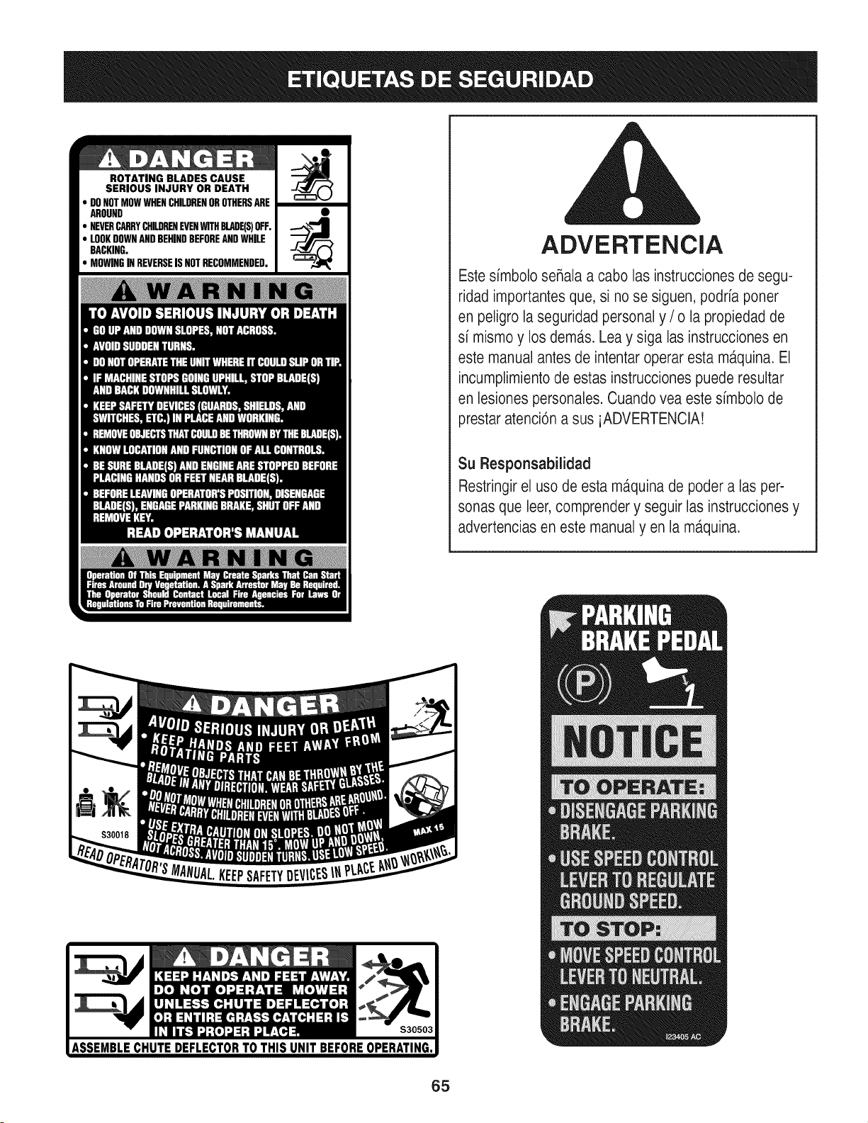
ROTATING BLADES CAUSE
SERIOUS INJURY OR DEATH
DONOTMOWWHENCHILDRENOROTHERSARE
AROUND
NEVERCARRYCHILDRENEVENWITHBLADE(S)OFF.
LOOKDOWNANDBEHINDBEFOREANDWHILE
BACKING.
MOWINGINREVERSEISNOTRECOMMENDED.
ADVERTENCIA
Este simbolo seRalaa cabo las instrucciones de segu-
ridad importantesque, si no se siguen, podria poner
en peligro la seguridad personal y / o la propiedad de
si mismo y los dem,_s.Lea y siga las instrucciones en
este manual antes de intentar operar esta m_tquina.El
incumplimientode estas instruccionespuede resultar
en lesiones personales. Cuando vea este simbolo de
prestar atenci6n a sus iADVERTENCIA!
Su Responsabilidad
Restringirel uso de esta ma.quinade poder alas per-
sonas que leer,comprender y seguir las instruccionesy
advertencias en este manual yen la m,_quina.
65
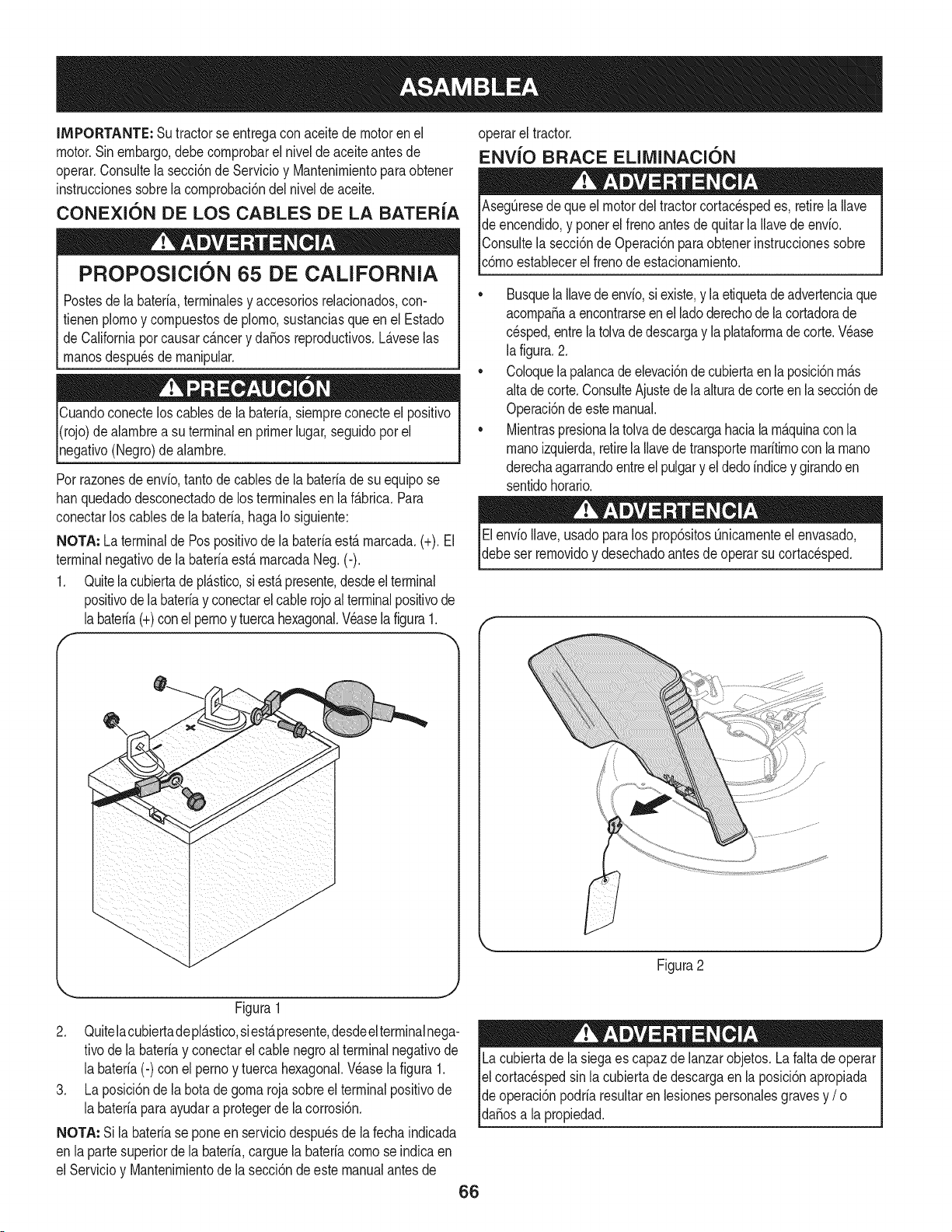
IMPORTANTE: Sutractorse entregaconaceitedemotoren el
motor.Sinembargo,debecornprobarel nivelde aceiteantes de
operar.Consultela secci6nde Servicioy Mantenirnientopara obtener
instrucdonessobrela cornprobad6ndel nivelde aceite.
CONEXION DE LOS CABLES DE LA BATERIA
PROPOSlClON 65 DE CALIFORNIA
Postesdela bateria,terrninalesy accesoriosrelacionados,con-
fienen plornoy cornpuestosde plorno,sustanciasqueen el Estado
de Californiaporcausarc_.ncery dafios reproducfivos.L_.veselas
rnanosdespu6sde rnanipular.
Cuandoconecteloscablesde la bateria,siernpreconecteel posifivo
I(rojo)de alarnbrea su terminalenprimerlugar,seguidoporel
pgafivo (Negro)de alarnbre.
Porrazonesde envio,tantode cablesde la bateriade su equipose
hanquedadodesconectadode los terrninalesen laf_.brica.Para
conectarlos cablesde la bateria,haga Io siguiente:
NOTA: La terminalde Pospositivode la bateriaest,. rnarcada.(+). El
terminalnegativode labateriaest&rnarcadaNeg. (-).
1. Quitela cubiertade pl&stico,si est&presente,desdeelterminal
positivode labateriay conectarelcablerojoal terminalpositivode
labateria(+)conel pernoy tuercahexagonal.Veasela figura1.
f
J
J
J
J
J
J
J
J
J
J
J
J
J
J
Figura1
2. Quitelacubiertadepl_.stico,siest,.presente,desdeelterminalnega-
tivode labateriay conectarel cablenegroal terminalnegativode
la bateria(-) con el pernoy tuercahexagonal.V6asela figura 1.
3. La posici6nde la botadegorna rojasobreel terminalpositivode
la bateriaparaayudara protegerde la corrosi6n.
NOTA: Si la bateriase pone en serviciodespuesde la fechaindicada
en lapartesuperiorde la bateria,carguela bateriacornose indicaen
el Servicioy Mantenirnientode la secci6nde este manualantesde
operarel tractor.
ENVlO BRACE ELIMINACI(SN
AsegQresedeque el motordel tractorcortacespedes, retirela Ilave
de encendido,y ponerel frenoantesde quitarla Ilavedeenvio.
IConsultela secci6nde Operaci6nparaobtenerinstruccionessobre
lc6rnoestablecerel frenode estacionarniento.
• Busquela Ilavedeenvio,siexiste,y laetiquetadeadvertenciaque
acornpafiaa encontrarseen el ladoderechode la cortadorade
cesped,entrelatolvade descargay la plataforrnade corte.V6ase
la figura.2.
• Coloquelapalancadeelevaci6ndecubiertaen laposici6nrn_.s
alta de corte.ConsulteAjustede la alturade corteen la secci6nde
Operaci6ndeestemanual.
• Mientraspresionala tolvade descargahaciala rn_.quinaconla
rnanoizquierda,retirela Ilavedetransporternaritirnoconla rnano
derechaagarrandoentreel pulgary el dedoindicey girandoen
sentidohorario.
ElenvioIlave,usadoparalos prop6sitosQnicarnenteel envasado,
debeser rernovidoy desechadoantesde operarsu cortacesped.
f
Figura2
Lacubiertade la siegaes capaz de lanzarobjetos.La faltade operar
el cortac6spedsin la cubiertade descargaen la posici6napropiada
de operaci6npodriaresultaren lesionespersonalesgravesy / o I
[dafiosa a propedad. ]
66
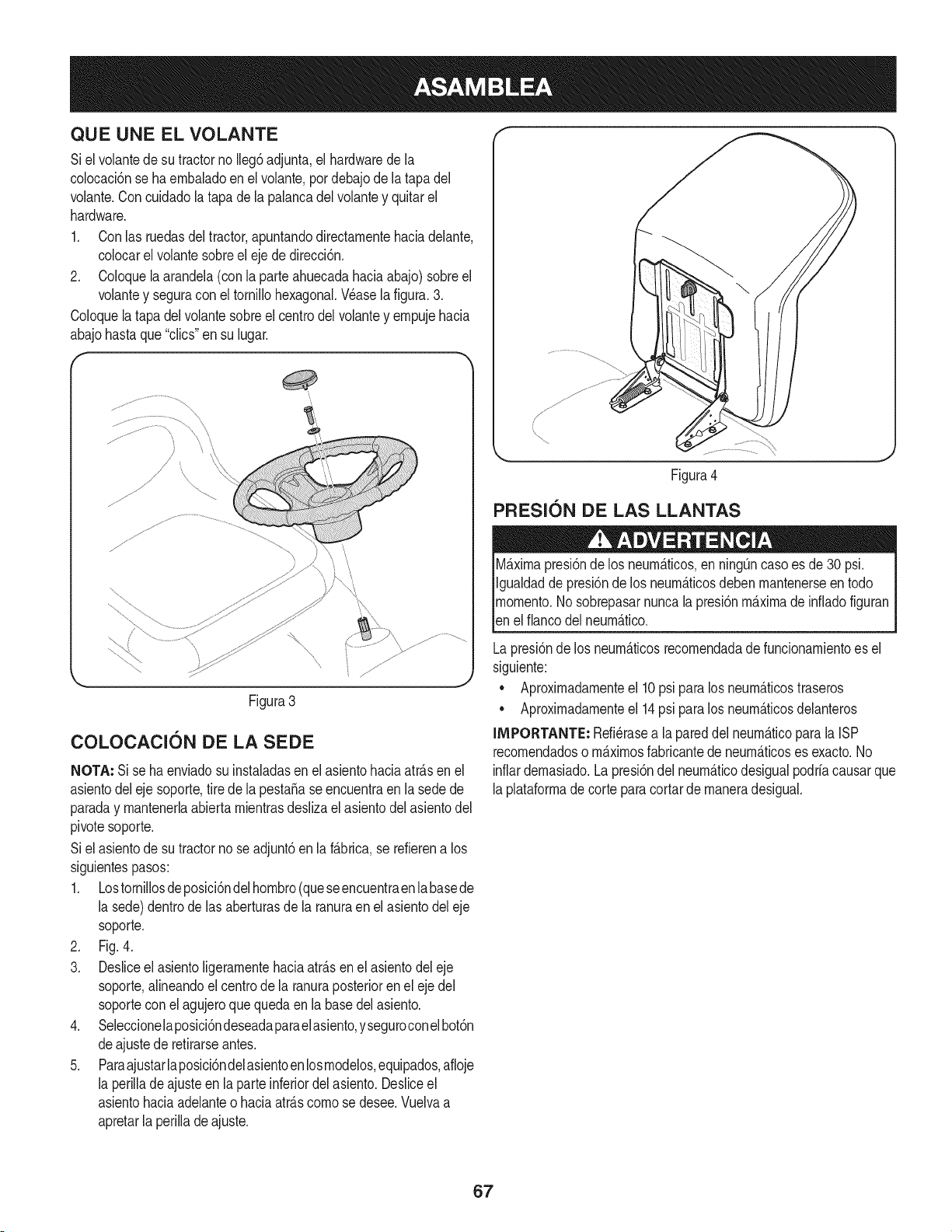
QUE UNE EL VOLANTE
Siel volantedesu tractorno Ileg6adjunta,el hardwarede la
colocaci6nse ha embaladoen el volante,por debajode la tapadel
volante.Concuidadola tapa dela palancadel volantey quitarel
hardware.
1. Conlas ruedasdel tractor,apuntandodirectamentehaciadelante,
colocarel volantesobreel eje de direcci6n.
2. Coloquela arandela(con la parteahuecadahaciaabajo) sobreel
volantey seguracon el tornillohexagonal.Wase la figura.3.
Coloquela tapadel volantesobreel centrodel volantey empujehacia
abajohastaque "clics"ensu lugar.
(
Figura3
COLOCACION DE LA SEDE
NOTA: Si se ha enviadosu instaladasen el asientohaciaatr&sen el
asientodeleje soporte,tire de la pesta5ase encuentraen la sedede
paraday mantenerlaabiertamientrasdeslizael asientodelasientodel
pivotesoporte.
Siel asientode sutractorno seadjunt6en la f&brica,se refierena los
siguientespasos:
1. Lostornillosdeposici6ndelhombro(queseencuentraenlabasede
la sede)dentrode las aberturasde la ranuraen elasientodel eje
soporte.
2. Fig. 4.
3. Desliceel asientoligeramentehaciaatr&senel asientodel eje
soporte,alineandoel centrode la ranuraposterioren el eje del
soporteconel agujeroque quedaen la basedelasiento.
4. Seleccionelaposici6ndeseadaparaelasiento,yseguroconelbot6n
deajustede retirarseantes.
5. Paraajustarlaposici6ndelasientoen losmodelos,equipados,afloje
la perilladeajuste en la parteinferiordel asiento.Desliceel
asientohaciaadelanteo haciaatr&scomo se desee.Vuelvaa
apretarla perillade ajuste.
Figura4
PRESlON DE LAS LLANTAS
M_ximapresi6nde los neurn_ticos,en ning_ncaso es de30 psi.
Igualdadde presi6nde los neumb.ticosdebenmantenerseen todo
momento.Nosobrepasarnuncalapresi6nm&ximade infladofiguran
_ene f anco de neum&tco.
Lapresi6nde los neumb.ticosrecomendadade funcionamientoes el
siguiente:
• Aproximadamenteel 10psi para los neum&ticostraseros
• Aproximadamenteel 14psi para los neumb.ticosdelanteros
IMPORTANTE: Refi_rasea lapareddel neum&ticopara la ISP
recomendadoso m&ximosfabricantede neum&ticoses exacto.No
inflardemasiado.Lapresi6ndel neumb.ticodesigualpodriacausarque
laplataformade corteparacortarde maneradesigual.
67
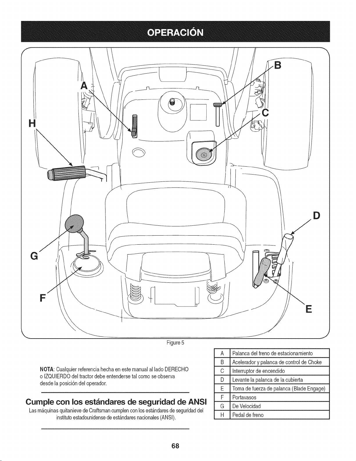
H
B
D
G
F
E
Figure5
A Palancadelfreno deestacionamiento
B Aceleradory palancade controlde Choke
C Interruptorde encendido
D Levantelapalancade la cubierta
E Tomade fuerzade palanca(BladeEngage)
F Portavasos
G DeVelocidad
H Pedalde freno
NOTA:Cualquierreferenciahechaen este manualal lado DERECHO
o IZQUIERDOdeltractordebeentendersetal comose observa
desde la posici6ndel operador.
Curnple con los est_ndares de seguridad de ANSI
Lasm_.quinasquitanievedeCraftsmancumplenconlosest_.ndaresdeseguridaddel
institutoestadounidensedeest_.ndaresnacionales(ANSi).
68
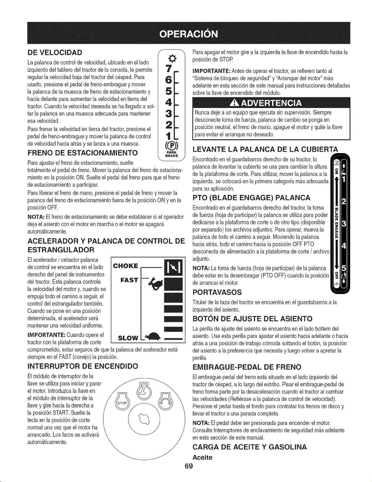
DE VELOCIDAD
La palancade controlde velocidad,ubicadoen el lado
izquierdodel tablerodel tractorde la consola,le perrnite
regularlavelocidadbaja del tractordel cesped.Para
usarlo,presioneel pedalde freno-ernbraguey mover
la palancadela rnuescade frenode estacionarnientoy
haciadelantepara aurnentarla velocidaden tierra del
tractor.Cuandola velocidaddeseadase haIlegadoa sol-
tar la palancaen una rnuescaadecuadapara rnantener
esavelocidad.
Parafrenarla velocidaden tierra deltractor,presioneel
pedalde freno-ernbraguey moverla palancade control
develocidadhaciaatr_.sy se lanzaa una rnuesca.
FRENO DE ESTACIONAIVIIENTO
PARK
BRAKE
Paraajustarel frenode estacionarniento,suelte
totalrnenteel pedal de freno. Moverlapalancadel frenodeestaciona-
rnientoen laposici6nON. Suelteel pedaldel frenoparaque el freno
deestacionarnientoa participar.
Paraliberarel frenode rnano,presioneel pedalde frenoy moverla
palancadel frenode estacionarnientofuerade la posici6nONyen la
posici6nOFE
NOTA: Elfreno deestacionarnientose debeestablecersi el operador
dejael asientocon el motoren rnarchao el motorse apagar_.
autorn_.ticarnente.
ACELERADOR Y PALANCA DE CONTROL DE
ESTRANGULADOR
Elacelerador/ cebadorpalanca
decontrol seencuentraen el lado
derechodelpanel de instrurnentos
deltractor.Estapalancacontrola
la velocidaddelmotory, cuandose
ernpujatodo el carninoa seguir,el
controldelestranguladortarnbi_n.
Cuandose poneenunaposici6n
deterrninada,el aceleradorser_.
rnantenerunavelocidaduniforrne.
IMPORTANTE: Cuandoopereel
tractorcon la plataforrnade corte
SLOW
cornprornetido,estar segurosde que la palancadel aceleradorest,.
siernpreenel FAST(conejo)la posici6n.
INTERRUPTOR DE ENCENDIDO
Elrn6dulode interruptorde la
Ilavese utilizapara iniciary parar
el motor.IntroduzcalaIlaveen
el rn6dulode interruptorde la
Ilavey gire haciala derechaa
la posici6nSTART.Sueltela
teclaen la posici6nde corte
normalunavezque el motorha
arrancado.Losfaros seactivar_.
autorn_.ticarnente.
Paraapagarel motorgirea la izquierdala Ilavede encendidohastala
posici6nde STOR
IMPORTANTE: Antesde operarel tractor,se refierentanto al
"Sisternade bloqueodeseguridad"y "Arranquedelmotor"rn_.s
adelanteen esta secci6nde este manualparainstruccionesdetalladas
sobrela Ilavedeencendidodel rn6dulo.
Nuncadejea un equipoqueejecutasin supervisi6n.Siernpre
desconectetornade fuerza,palancade carnbiose pongaen
posici6nneutral,elfreno dernano,apagueel motory quite laIlave
paraevitarel arranqueno deseado.
LEVANTE LA PALANCA DE LA CUBIERTA
Encontradoenel guardabarrosderechodesu tractor,la
palancade levantarla cubierta se usapara carnbiarla altura
de la plataforrnadecorte. Parautilizar,moverla palancaa la
izquierda,se colocar_,en laprirneracategoriarn_.sadecuada
parasu aplicaci6n.
PTO (BLADE ENGAGE) PALANCA
Encontradoenel guardabarrosderechodeltractor,la torna
de fuerza(hojade participar)la palancase utilizaparapoder
dedicarsea laplataforrnade corte o de otto tipo(disponible
porseparado)los archivosadjuntos.Paraoperar,rnuevala
palancade todo elcarninoa seguir.Moviendola palanca
haciaatr_.s,todo el carninohacia laposici6nOFFPTO
desconectade alirnentaci6na la plataforrnade corte/ archivo
adjunto.
NOTA: Latornadefuerza (hojade participar)de la palanca
debeestar en la desernbragar(PTOOFF)cuandola posici6n
de arrancarel motor.
PORTAVASOS
Titulardela taza del tractorse encuentraen el guardabarrosa la
izquierdadelasiento.
BOTON DE AJUSTE DEL ASIENTO
Laperillade ajustedel asientose encuentraen elladobotterndel
asiento.Useesta perilla paraajustarel asientohaciaadelanteo hacia
atr_.sa unaposici6ndetrabajoc6rnodasoltandoel bot6n,la posici6n
del asientoa lapreferenciaque necesitay luegovolvera apretarla
perilla.
EIVIBRAGUE-PEDAL DE FRENO
Elernbrague-pedaldelfrenoest,.situadoen el lado izquierdodel
tractorde cesped,a Io largodelestribo.Pisarel ernbrague-pedalde
frenoforrnaparteporla desaceleraci6ncuandoel tractoralcarnbiar
lasvelocidades(Refi_rasea la palancade controlde velocidad).
Presioneel pedalhastael rondoparacontratarlos frenosde discoy
Ilevarel tractora una paradacornpleta.
NOTA: Elpedaldebe serpresionadaparaencenderel motor.
ConsulteInterruptoresde enclavarnientode seguridadrn_.sadelante
en estasecci6nde este manual.
CARGA DE ACEITE Y GASOLINA
Aceite
69
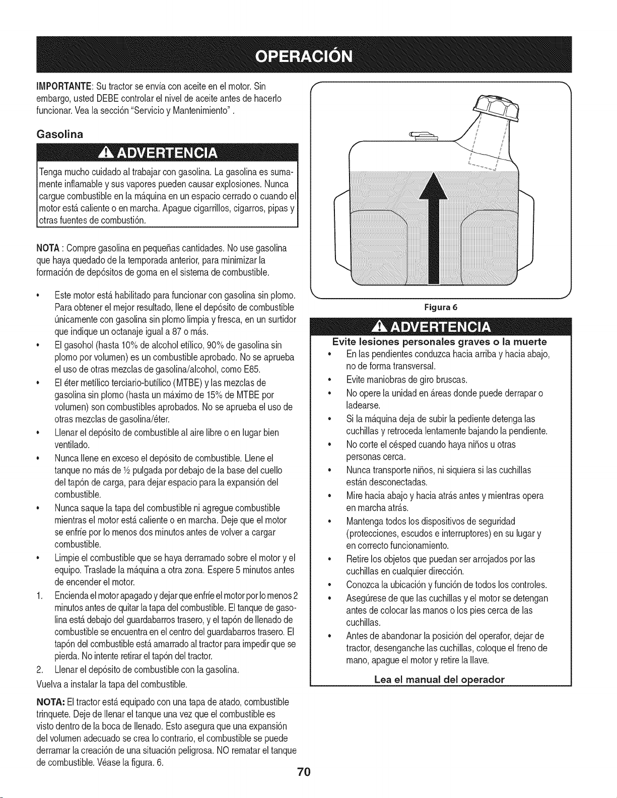
IMPORTANTE:Su tractorse enviacon aceiteen el motor.Sin "" "
embargo,ustedDEBEcontrolarel nivelde aceiteantesde hacerlo
fundonar.Veala secci6n"ServMoy Mantenirniento".
Gasolina
Tengarnuchocuidadoal trabajarcon gasolina.Lagasolinaes surna-
rnenteinflarnabley sus vaporespuedencausar explosiones.Nunca
carguecombustibleen la rn_.quinaen unespaciocerradoo cuandoel
motorest,.calienteo en rnarcha.Apaguecigarrillos,cigarros,pipasy
otrasfuentesde cornbusti6n.
NOTA: Cornpregasolinaen peque_ascantidades.No usegasolina
quehayaquedadode la ternporadaanterior,pararninirnizarla
forrnaci6nde dep6sitosdegornaen el sisternadecombustible.
• Estemotorest,.habilitadoparafuncionarcon gasolinasinplorno.
Paraobtenerel rnejor resultado,Ileneel dep6sitodecombustible
0nicarnentecongasolinasin plornolirnpiay fresca,enun surtidor
queindiqueun octanajeigual a 87 o rn_.s.
• Elgasohol(hasta 10%de alcoholetilico,90% de gasolinasin
plornoporvolurnen)es un combustibleaprobado.No seaprueba
el usode otrasrnezclasde gasolina/alcohol,cornoE85.
• El_ter rnetilicoterciario-butilico(MTBE)y las rnezclasde
gasolinasin plorno(hastaun rn_.xirnode 15%de MTBEpor
volurnen)son combustiblesaprobados.No se apruebaeluso de
otrasrnezclasdegasolina/eter.
• Llenarel dep6sitode combustibleal airelibreo enlugarbien
ventilado.
• NuncaIleneen excesoel dep6sitode combustible.Lleneel
tanqueno rn_.sde 1/2pulgadapor debajode la basedelcuello
deltap6nde carga,para dejarespacioparala expansi6ndel
combustible.
• Nuncasaquela tapadelcombustibleni agreguecombustible
rnientrasel motorest,.calienteo en rnarcha.Dejeque el motor
se enfrieporIo rnenosdos rninutosantesde volvera cargar
combustible.
• Lirnpieel combustiblequese hayaderrarnadosobreel motory el
equip&Trasladela rn_.quinaa otra zona.Espere5 rninutosantes
deencenderel motor.
1. Enciendaelmotorapagadoy dejarqueenfrieel motorporIornenos2
rninutosantesdequitarla tapadel combustible.Eltanquede gaso-
linaest,.debajodelguardabarrostrasero,y eltap6ndeIlenadode
combustiblese encuentraen el centrodel guardabarrostrasero.El
tap6ndel combustibleest,.arnarradoaltractorparairnpedirquese
pierda.Nointenteretirarel tap6ndeltractor.
2. Llenarel dep6sitode combustiblecon la gasolina.
Vuelvaa instalarlatapa delcombustible.
NOTA: Eltractorest,.equipadocon unatapade atado,combustible
trinquete.Dejede Ilenarel tanqueunavez que el combustiblees
vistodentrodela bocade Ilenado.Estoaseguraqueuna expansi6n
delvolurnenadecuadose crea Iocontrario,el combustiblese puede
derrarnarlacreaci6nde unasituaci6npeligrosa.NO rernatarel tanque
decombustible.Wase la figura.6.
J
Figura 6
Evite lesiones personales graves o la muerte
• Enlas pendientesconduzcahaciaarribay haciaabajo,
no deforrnatransversal.
• Eviternaniobrasdegirobruscas.
• Noopere la unidaden &reasdondepuedederraparo
ladearse.
• Si la rn&quinadejadesubirla pedientedetengalas
cuchillasy retrocedalentarnentebajandola pendiente.
• Nocorte el c_spedcuandohayaniSosu otras
personascerca.
• NuncatransporteniSos,ni siquierasi las cuchillas
estAndesconectadas.
• Mirehaciaabajoy haciaatrAsantes y rnientrasopera
en rnarchaatrAs.
• Mantengatodoslosdispositivosdeseguridad
(protecciones,escudose interruptores)en su lugary
en correctofuncionarniento.
• Retirelosobjetosque puedanser arrojadosporlas
cuchillasen cualquierdirecci6n.
• Conozcala ubicaci6ny funci6ndetodoslos controles.
• Aseg0resedeque lascuchillasy el motorse detengan
antesde colocar lasrnanoso los piescerca de las
cuchillas.
• Antesde abandonarla posici6ndeloperafor,dejarde
tractor,desenganchelas cuchillas,coloqueelfrenode
rnano,apagueel motory retirela Ilave.
Lea el manual del o erador
70
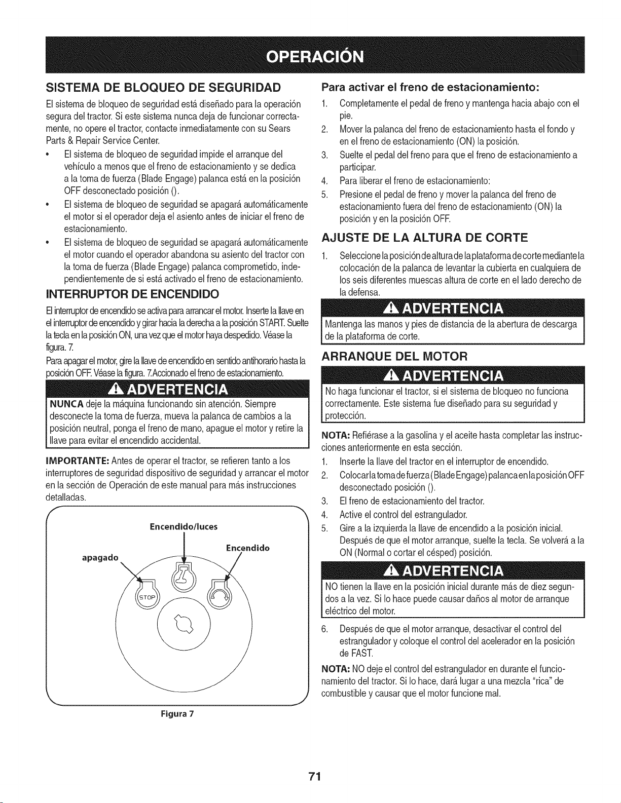
SISTEMA DE BLOQUEO DE SEGURIDAD
Elsisternade Noqueode seguridadest,.diseSadoparala operaci6n
seguradel tractor.Si estesisternanuncadejade funcionarcorrecta-
rnente,no opereel tractor,contacteinrnediatarnentecon suSears
Parts& RepairServiceCenter.
• Elsisternade bloqueode seguridadirnpideel arranquedel
vehiculoa rnenosqueel frenode estacionarnientoy se dedica
a latornade fuerza (Blade Engage)palancaest,. en laposici6n
OFFdesconectadoposici6n0.
• Elsisternade bloqueode seguridadseapagar_,autorn_.ticarnente
el motorsi el operadordeja el asientoantesde iniciarel frenode
estacionarniento.
• Elsisternade Noqueode seguridadseapagar_,autorn_.ticarnente
el motorcuandoel operadorabandonasuasientodel tractorcon
la tornadefuerza (Blade Engage)palancacornprornetido,inde-
pendienternentede si est,. activadoel frenodeestacionarniento.
INTERRUPTOR DE ENCENDIDO
Elinterruptordeencendidoseactivaparaarrancarel motor.Insertela Ilaveen
elinterruptordeencendidoy girarhacialaderechaa laposici6nSTART.Suelte
lateclaenlaposici6nON,unavezqueel motorhayadespedido.Wasela
figura.Z
Paraapagarelmotor,girelaIlavede encendidoen sentidoantihorariohastala
_osici6nOFEWaselaligura.ZAccionadoelfrenodeestacionarniento.
NUNCA dejela rn_.quinafuncionandosin atenci6n.Siernpre
desconectelatornade fuerza,rnuevala palancade carnbiosa la
posici6nneutral,pongaelfrenode rnano,apagueel motory retirela
Ilaveparaevitarel encendidoaccidental.
IMPORTANTE: Antes de operarel tractor,se refierentantoa los
interruptoresde seguridaddispositivode seguridady arrancarel motor
enla secci6nde 0peraci6n deeste manualpara rn&sinstrucciones
detalladas.
Encendido/luces
apagado
Encendido
Figura 7
Para activar el freno de estacionamiento:
1. Cornpletarnenteel pedalde frenoy rnantengahaciaabajo conel
pie.
2. Moverlapalancadel frenode estacionarnientohastael rondoy
en elfrenode estacionarniento(ON)la posici6n.
3. Suelteel pedaldelfreno paraque el frenode estacionarnientoa
participar.
4. Paraliberarel frenode estacionarniento:
5. Presioneel pedalde frenoy moverla palancadelfreno de
estacionarnientofueradel frenode estacionarniento(ON)la
posici6nyen la posici6nOFE
AJUSTE DE LA ALTURA DE CORTE
Seleccionelaposici6ndealturadelaplataforrnadecorternediantela
colocaci6nde lapalancade levantarla cubiertaen cualquierade
losseis diferentesrnuescasalturadecorte en el ladoderechode
ladefensa.
Mantengalas rnanosy pies de distanciade la aberturadedescarga
de laplataforrnade corte.
ARRANQUE DEL MOTOR
Nohaga funcionarel tractor,si el sisternade bloqueonofunciona
correctarnente.Estesisternarue dise_adoparasu seguridady
protecci6n.
NOTA: Refi_rasea la gasolinay el aceitehastacornpletarlasinstruc-
clonesanteriorrnenteenesta secci6n.
1. Insertela Ilavedel tractorenel interruptorde encendido.
2. Colocarlatornadefuerza(BladeEngage)palancaenlaposici6nOFF
desconectadoposici6n0.
3. Elfrenode estacionarnientodel tractor.
4. Activeel controldelestrangulador.
5. Girea la izquierdala Ilavede encendidoa la posici6ninicial.
Despu_sde queel motorarranque,sueltelated& Sevolver_,a la
ON(Normalo cortarel c_sped)posici6n.
NOtienenla Ilaveen la posici6ninicialdurantern_.sde diezsegun-
dos a la vez. SiIo hacepuedecausardaSosal motorde arranque
el_ctricodel motor.
6. Despu_sde queel motorarranque,desactivarel controldel
estranguladory coloqueel controldelaceleradoren la posici6n
de FAST.
NOTA: NOdeje el controldel estranguladoren duranteelfuncio-
narnientodel tractor.Si Io hace,dar_.lugarauna rnezcla"rica"de
combustibley causarque el motorfuncionernal.
71
PARO DEL MOTOR
Sise golpea un objetoextra,o, detengael motor,desconecteel
cablede la bujfa(s) y tierra contrael motor.Inspeccionarcuidadosa-
menteelequipo de los da_os.Reparaci6ndelos da_osantesde
rencar y de funconamento.
1. Si sededicanalas hojas,colocarla tomade fuerza(Blade
Engage)palancaen la posici6nOFFdesconectadoposici6nO.
2. Gire a la izquierdala Ilavede encendidoa la posici6nSTOR
3. Retirela Ilavede la Ilavede encendidoparaevitarel arranqueno
deseado.
LA CONDUCCION DEL TRACTOR
Evitecomienzapronto,el excesodevelocidady paradasbruscas.
Nodeje el asientodel tractor,sin colocarla tomadefuerza(Blade
Engage)palancaen laposici6nOFF desembragar0 posici6n,
presionandoel pedalde frenoy accionadoel frenode estaciona-
miento.Si no puedesalirdeltractorsin vigilancia,tambi_na suvez
la Ilavedeencendidoapagadoy quitarla Ilave.
Siempremire haciaabajo y detr_.santesy durantelacopiade
seguridadpara evitarla copiadem_.sde unaccidente.
Pisarel embrague-pedalde frenoparaliberarel frenodeestaciona-
mientoy dejarqueel pedal.
Moverla palancadel aceleradorenel FAST(conejo)laposici6n.
Coloquela palancade cambiostanto en la posici6ninversao
FORWARD.
IMPORTANTE:NOutilizarla palancade cambiosparacambiarla
direcci6ndela marchacuandoel tractorest_en movimiento.Siempre
utiliceel frenode pedalde embragueparaque el tractora unaparada
completaantesde pasar.
Suelteel frenodeestacionamientopresionandoelembrague-pedalde
frenoy el posicionamientode la palancade controldevelocidadenla
posici6ndeseada.
EnprimerlugarIMPORTANTE:-tiempo,los operadoresdebenutilizar
posicionesdevelocidadde 1 o 2. Convi_rtetetotalmentefamiliarizado
con el funcionamientodel tractory loscontrolesantesde operarel
tractoren lospuestosde mayorvelocidad.
Embrague-pedalde freno lentamenteparacolocarlaunidaden
movimiento.
Eltractorde c_spedes Ilevadoa una paradapresionandoel
embrague-pedalde freno.
NOTA:Cuandooperela unidadinicial,habr_,pocadiferenciaentrelas
dos velocidadesm_.saltashastadespu_sde los cinturonesse ban
sentadoen laspoleasduranteel periodode rodaje.
Antesde abandonarla posici6ndel operadorporcualquierraz6n,
separarlashojas,ponerla palancade control de velocidaden
neutral,pongael frenode estacionamiento,paradamotorapagadoy
quitarla llave.
IMPORTANTE:AI pararel tractor,porcualquiermotivo,mientrasque
en unasuperficiede hierba,siempre:
1. Coloquela palancade cambiosen puntomuerto,
2. Apliqueel frenodeestacionamiento,
3. Apagueel motory quitar la Ilave.Si Io hace,reducir_,al minimola
posibilidaddeque sucespedsedore'"'porel escapecalientedel
motorde su tractor.
72
Si seestancala unidadcon el controlde velocidadenalta velocidad,
o si la unidadno funcionar_,con la palancade controlde velocidaden
condicionesde bajavelocidad,sigaestos pasos:
1. La palancade carnbiosen puntornuerto.
2. Reinicieel motor.
3. Coloquela palancade controlde velocidaden la posici6nrn_.s
altavelocidad.
4. Ernbrague-pedaldefrenocornpletarnente.
5. Pisarel ernbrague-pedalde freno.
6. Coloquela palancade controlde velocidaden la posici6n
deseada.
7. Coloquela palancade carnbiosen cualquieradeavanceo retro-
ceso,y seguirlos procedirnientosnorrnalesde funcionarniento.
CONDUCCION EN LAS LADERAS
Refierenal anchode la pendienteen la seguridadde las pr_.cticasde
operaci6nirnportantesecci6ndelmanualpara ayudara deterrninar
zonasde laderadondepuedeoperarel tractorcon totalseguridad.
Nocorte el cespeden pendientescon unainclinaci6nde rn_.sde 15
grados(unaurnentode aproxirnadarnente2-1/2pies cada 10pies).
Eltractorpuedevolcary causarlesionesgraves.
INVOLUCRAR A LOS BLADES
Participaci6nde la tornade fuerza(Blade Engage)lastransferenciasde
energiaala plataforrnade corteo de otto tipo(disponibleporseparado)
losarchivosadjuntos.Paraparticiparde lashojas,hagaIosiguiente:
1. Moverla palancade controldel aceleradora la r_.pida(conejo)la
posici6n.
2. Sujetela tornade fuerza(BladeEngage)y girar la palancade
todo el carninoa seguira los novios(ON) la posici6n.
3. Mantengala palancadel aceleradoren el FAST(conejo)la
posici6nparael usorn_.seficientede la plataforrnade corte o de
otro tipo (disponibleporseparado)los archivosadjuntos.
IMPORTANTE: Enel reversoPrecauci6nrnodoque el motorse
apagar_,autorn_.ticarnentesi latornadefuerza est,. comprornetidacon
lapalancade controlde velocidaden la posici6ninversaparaviajar
con la Ilavede encendidoen la posici6nnormalde siega.
USO DE LA CUBIERTA DE LEVANTE LA
PALANCA DE
Paraelevarla plataforrnade corte,moverla palancade elevaci6nde
cubiertaa la izquierda,luegosecolocaen la ranurarn_.sadecuada
parasu aplicaci6n.ConsulteAjuste la alturade corteanteriorrnenteen
estasecci6n.
• Corteel c_spedy las pendientes,nuncatransversal.
Tengaextrernaprecauci6nalcarnbiarde direcci6nen las
pendientes.
Watchparalos agujeros,grietas,baches,piedrasu otros objetos
ocultos.Terrenoirregularpuederevertirla rn_.quina.Elcesped
altopuede ocultarobst_.culos.
Evitegirarcuandosecircula por una pendiente.Si unavez,debe
hacerse,a suvez por la pendiente.El regresode unapendiente
aurnentala posibilidadde un rollover.
Evitedetenersecuandoseconducepot unapendiente.Si es
necesariodetenerrnientrasse conducepot una pendiente,
puestaen rnarchasinproblernasy con cuidadopara reducirla
posibilidadde volteareltractorhaciaatr_.s.
73
CORTAR
Paraayudara evitar el contactocon lacuchillao unalesi6nen
elobjetolanzado,Mantengaa los espectadores,losayudantes,
los niSosy las mascotaspor Io menos75piesde distandade la
m_.quinamientrasest,. en fundonamiento.Paradade la m_.quina,si
alguienentraen el _.rea.
La siguienteinformaci6nser_.Qfilcuandose ufiliza la plataformade
corteconsu tractor:
Plande su patr6nde corte paraevitar la descargade materiales
hada lascarreteras,aceras,transeQntes,etc. Adem_.s,evite material
quese descargacontraunaparedo unaobstrucd6nque puede
causaralta materiala rebotarhaciael operador.
FAROS
• LasI&mparasest&nONcuandoel motordeltractorse est&
ejecutando.
• Lasluces seapagacuandola Ilavede contactose muevea la
posici6nSTOR
• Nocorteel c6speda la velocidadde terrenoelevado,especial-
mentesi se ha instaladoun kitde mantilloo colectorde cesped.
• Paraobtenerlos mejoresresultadosse recomiendaque las
dos primerasvueltassecortar&conla aprobaci6nde la gesti6n
arrojadohaciael centro.Tras lasdos primerasvueltas,invertirel
sentidode lanzarla descargahaciael exteriorde la balanzade
corte.Esto le dar&una mejoraparienciaal cesped.
• Nocorteelcespeddemasiadocorto.Pastocortoinvitacrecimiento
demalashierbasy losamarilloscon rapidezenel tiemposeco.
• Cortarel cespedsiemprese debe hacercon el motora todogas.
• Bajolascondicionesm_.spesadas,puedeser necesariovolver
sobrela zona delcortepor segundavez para obtenerun corte
limpio.
• NOintentecortarespesamalezay malashierbasy elpastomuyalto.
Sutractorestadise_adoparacortarelc6sped,uncepillonoest_claro.
• Mantengalas cuchillasafiladasy sustituirlas cuchillasencaso
dedesgaste.ConsulteHojasde corte en el servicioy la secci6n
Mantenimientode estemanualde instruccionesde afilar lahoja
adecuada.
74
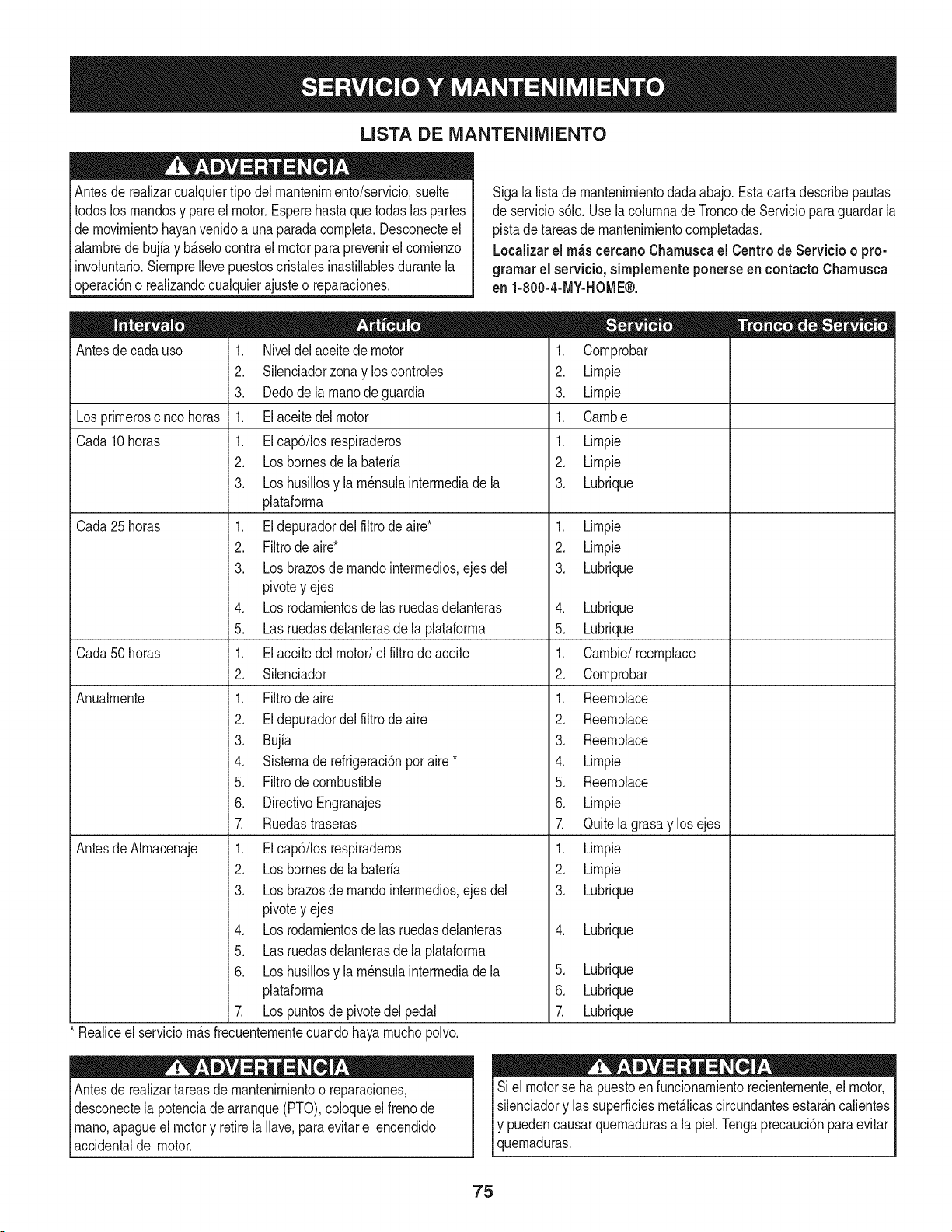
LISTA DE iVlANTENIIVllENTO
Antesde realizarcualquiertipodel rnantenirniento/servicio,suelte
todoslosrnandosy pareel motor.Esperehastaquetodaslaspartes
de rnovirnientohayanvenidoa unaparadacornpleta.Desconecteel
alarnbrede bujiay b_.selocontrael motorpara prevenirel cornienzo
involuntario.SiernpreIleve puestoscristalesinastillablesdurantela
operaci6no realizandocualquierajusteo reparaciones.
Sigala listade rnantenirnientodadaabajo.Estacartadescribepautas
de servicios61o.Use la colurnnade Troncode Servicioparaguardar la
pistade tareasdernantenirnientocornpletadas.
Localizarel rn_scercanoChamuscael Centrode Servicio o pro-
gramar el servicio,simplementeponerseen contactoChamusca
en 1-800-4-MY-HOME®.
Antesde cadauso
Los prirneroscinco horas
Cada 10horas
Cada25 horas
Cada50 horas
Anualrnente
Antesde Alrnacenaje
1. Niveldel aceitede motor
2. Silenciadorzonay loscontroles
3. Dedode la rnanode guardia
1. El aceitedel motor
1. EIcap6/Iosrespiraderos
2. Losbornesdela bateria
3. Loshusillosy la rn_nsulainterrnediade la
plataforrna
1. El depuradordelfiltro de aire*
2. Filtrode aire*
3. Losbrazosde rnandointerrnedios,ejes del
pivotey ejes
4. Los rodarnientosde las ruedasdelanteras
5. Las ruedasdelanterasde la plataforrna
1. El aceitedel motor/el filtrode aceite
2. Silenciador
1. Filtrode aire
2. Eldepuradordelfiltrode aire
3. Bujia
4. Sisternaderefrigeraci6nporaire*
5. Filtrode combustible
6. DirectivoEngranajes
7. Ruedastraseras
1. EIcap6/Iosrespiraderos
2. Loshomes de la bateria
3. Losbrazosde rnandointerrnedios,ejes del
pivotey ejes
4. Los rodarnientosde las ruedasdelanteras
5. Las ruedasdelanterasde la plataforrna
6. Loshusillosy la rn_nsulainterrnediade la
plataforrna
7. Lospuntosde pivotedel pedal
Realiceel serviciorn_.sfrecuenternentecuandohayarnuchopolvo.
Antesde realizartareasde mantenirnientoo reparaciones,
desconectela potenciadearranque(PTO),coloqueel frenode
rnano,apagueel motory retirela Ilave,paraevitar el encendido
accidentaldel motor.
.
2.
3.
1.
1.
2.
3.
Cornprobar
Lirnpie
Lirnpie
Carnbie
Lirnpie
Lirnpie
Lubrique
1. Lirnpie
2. Lirnpie
3. Lubrique
4. Lubrique
5. Lubrique
1. Carnbie/reernplace
2. Cornprobar
1. Reernplace
2. Reernplace
3. Reernplace
4. Lirnpie
5. Reernplace
6. Lirnpie
7. Quitelagrasay los ejes
1. Lirnpie
2. Lirnpie
3. Lubrique
4. Lubrique
5. Lubrique
6. Lubrique
Z Lubrique
Si el motorse ha puestoen funcionarnientorecienternente,el motor,
silenciadory las superficiesrnet_.licascircundantesestar_.ncalientes
Iy puedencausar quernadurasa la piel.Tengaprecauci6nparaevitar
[quernaduras.
75
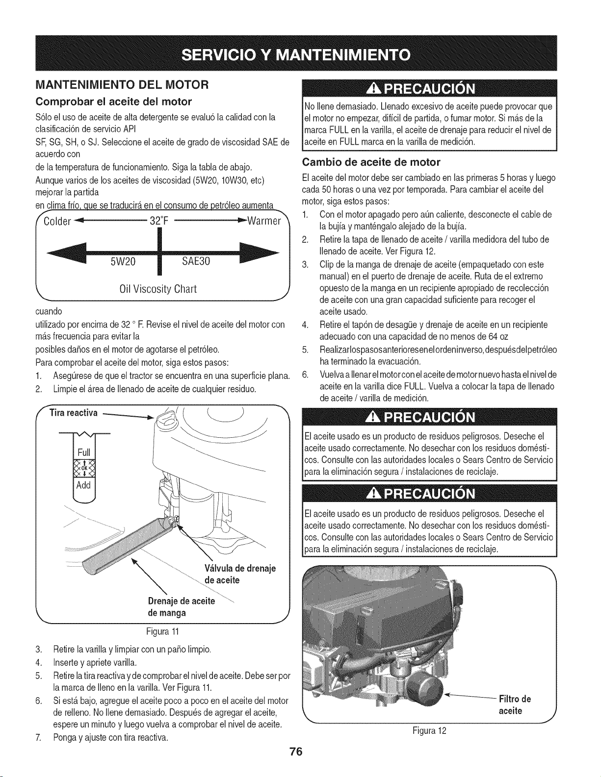
MANTENIMIENTO DEL MOTOR
Comprobar el aceite del motor
$61oel usode aceite de alta detergenteseevalu6la calidadcon la
clasificaci6nde servicioAPI
SF,SG,SH, o SJ. Seleccioneel aceitede gradode viscosidadSAEde
acuerdocon
de laternperaturadefuncionarniento.Siga la tablade abajo.
Aunquevariosdelos aceitesdeviscosidad(5W20,10W30,etc)
rnejorarla partida
enc!_ue se traducir_,en el consurnodepetr61eoaurnenta
Colder _ 32°F _Warmer
Oil Viscosity Chart
J
cuando
utilizadoporencirnade 32 o E Reviseel niveldeaceite del motorcon
rnAsfrecuenciaparaevitarla
posiblesdafiosen el motordeagotarseel petr61eo.
Paracornprobarel aceitedel motor,sigaestospasos:
1. AsegOresede que el tractorse encuentraen una superficieplana.
2. Lirnpieel _.reade Ilenadode aceitede cualquierresiduo.
f Tira reactiva
V_lvulade drenaje
de aceite
Drenajede aceite
de manga
Figura11
3. Retirela varillay lirnpiarconun patiolirnpio.
4. Insertey aprietevarilla.
5. Retirelatira reactivayde cornprobarelniveldeaceite.Debeserpor
la rnarcadellenoen la varilla.Ver Figura11.
6. Si est_ bajo,agregueel aceitepocoa pocoen elaceite del motor
de relleno.1/oIlenedernasiado.Despu_sde agregarel aceite,
espereun rninutoy luegovuelvaa cornprobarel nivelde aceite.
7. Pongay ajustecon tira reactiva.
76
No Ilenedernasiado.Llenadoexcesivode aceite puedeprovocarque
elmotorno ernpezar,diffcilde partida,o furnarmotor.Si rn_sde la
rnarcaFULLen lavarilla,el aceitede drenajepara reducirel nivelde
aceiteen FULLrnarcaen la varillade rnedici6n.
Cambio de aceite de motor
Elaceitedel motordebeset carnbiadoen las prirneras5 horasy luego
cada 50 horasouna vezpor ternporada.Para carnbiarel aceitedel
motor,sigaestospasos:
1. Con el motorapagadopero aOncaliente,desconecteel cablede
la bujiay rnant_ngaloalejadodela bujia.
2. Retirelatapa de Ilenadode aceite / varillarnedidoradel tubo de
Ilenadode aceite.Vet Figura12.
3. Clip de larnangadedrenajede aceite (ernpaquetadocon este
manual)en el puertode drenajede aceite.Rutade el extrerno
opuestode larnangaen un recipienteapropiadode recolecci6n
de aceitecon una gran capacidadsuficientepara recogerel
aceiteusado.
4. Retireel tap6nde desagOey drenajede aceiteenun recipiente
adecuadocon unacapacidaddeno rnenosde64 oz
5. Realizarlospasosanterioresenelordeninverso,despu_sdelpetr61eo
haterrninadolaevacuaci6n.
6. Vuelvaa Ilenarelrnotorconelaceitedemotornuevobasraelnivelde
aceiteen la varilladice FULL.Vuelvaa colocarla tapade Ilenado
de aceite/ varillade rnedici6n.
Elaceiteusadoes un productode residuospeligrosos.Desecheel
aceiteusadocorrectarnente.1/odesecharcon los residuosdorn_sti-
cos.Consultecon lasautoridadeslocaleso SearsCentrodeServicio
_aralaelirninaci6nsegura/instalacionesde reciclaje.
Elaceiteusadoes un productode residuospeligrosos.Desecheel
aceiteusadocorrectarnente.1/odesecharcon los residuosdorn_sti-
cos.Consultecon lasautoridadeslocaleso SearsCentrodeServicio
[para a e rnnac6n segura/ nstaac onesde recc aje.
Figura12
Filtrode
aceite
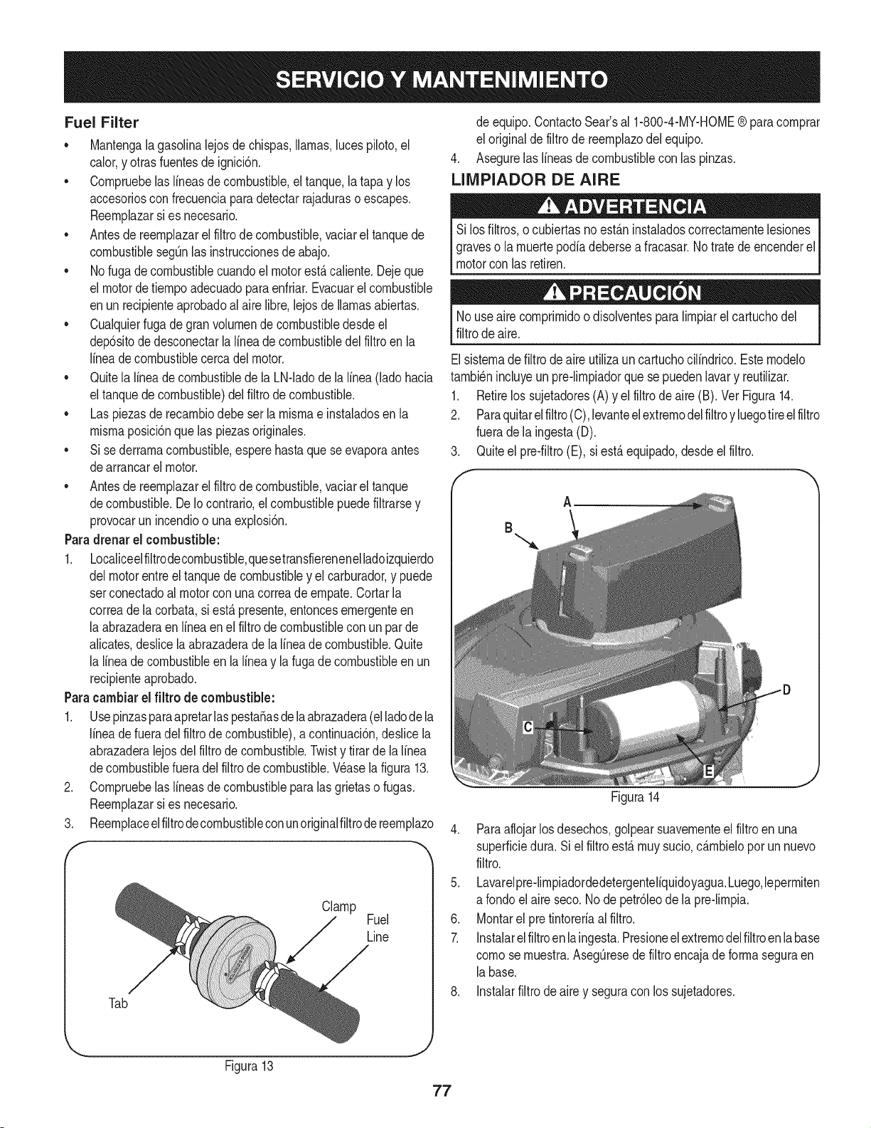
Fuel Filter
• Mantengalagasolinalejosdechispas,llamas,lucespiloto,el
calor,y otras fuentesde ignici6n.
• Compruebelas lineasde combustible,el tanque,la tapay los
accesoriosconfrecuenciapara detectarrajaduraso escapes.
Reemplazarsi es necesario.
• Antesde reemplazarel filtrodecombustible,vaciarel tanquede
combustiblesegQnlas instruccionesdeabajo.
• No fugadecombustiblecuandoel motorest,.caliente.Dejeque
el motordetiempoadecuadopara enfriar.Evacuarel combustible
enun recipienteaprobadoal airelibre,lejosde llamasabiertas.
• Cualquierfuga degran volumende combustibledesdeel
dep6sitode desconectarlalineade combustibledel filtroen la
lineade combustiblecercadel motor.
• Quitela linea de combustiblede la LN-ladode la linea (ladohacia
el tanquede combustible)delfiltrode combustible.
• Las piezasde recambiodebe serla mismae instaladosenla
mismaposici6nque las piezasoriginales.
• Si sederramacombustible,esperehastaque seevaporaantes
dearrancarel motor.
• Antesde reemplazarel filtrodecombustible,vaciarel tanque
decombustible.DeIocontrario,el combustiblepuedefiltrarsey
provocarun incendioo unaexplosi6n.
Paradrenarel combustible:
1. Localiceelfiltrodecombustible,quesetransfierenenelladoizquierdo
delmotorentreel tanquedecombustibley el carburador,y puede
setconectadoal motorcon unacorreade empate.Cortarla
correade la corbata,si est,.presente,entoncesemergenteen
la abrazaderaenIfneaenel filtrode combustiblecon un par de
alicates,deslicelaabrazaderade la lineade combustible.Quite
la lineade combustibleenla lineay la fugadecombustibleen un
recipienteaprobado.
Paracambiarel filtrode combustible:
1. Usepinzasparaapretarlaspesta_asde la abrazadera(elladode la
lineade fueradel filtrode combustible),a continuaci6n,deslicela
abrazaderalejosdel filtrode combustible.Twisty tirarde la linea
decombustiblefueradel filtro de combustible.Wase la figura 13.
Compruebelas lineasde combustibleparalas grietaso fugas.
Reemplazarsi es necesario.
Reemplaceelfiltrodecombustibleconunoriginalfiltrode teemplazo
.
3.
f
Clamp
Fuel
Line
Tab
de equipo.ContactoSear'sal 1-800-4-MY-HOME® paracomprar
el originalde filtrode reemplazodelequipo.
4. Asegurelas lineasde combustiblecon las pinzas.
LIIVIPIADOR DE AIRE
Si losfiltros, o cubiertasno est_.ninstaladoscorrectamentelesiones
graveso la muertepodiadebersea fracasar.Notratede encenderel
motorcon las retiren.
Nouseaire comprimidoodisolventesparalimpiarel cartuchodel
filtrodeaire.
Elsistemade filtrodeaire utilizauncartuchocilindrico.Estemodelo
tambi_nincluyeun pre-limpiadorque sepuedenlavary reutilizar.
1. Retirelos sujetadores(A) y el filtrode aire(B). Vet Figura14.
2. Paraquitarelfiltro(C),levanteelextremodelfiltroy luegotireelfiltro
fuerade la ingesta(D).
3. Quiteel pre-filtro(E), si est,.equipado,desdeel filtro.
A
B
Figura14
J
4. Paraaflojarlosdesechos,golpearsuavementeel filtroen una
superficiedura. Si el filtro est,. muy sucio,c_.mbieloporun nuevo
filtro.
5. Lavarelpre-limpiadordedetergenteliquidoyagua.Luego,lepermiten
a rondoel aireseco.No de petr61eode la pre-limpia.
6. Montarel pretintoreriaalfiltro.
7. Instalarel filtroen laingesta.Presioneel extremodelfiltroenla base
comose muestra.AsegQresede filtroencajadeforma seguraen
labase.
8. Instalarfiltrodeairey seguracon los sujetadores.
Figura13
77
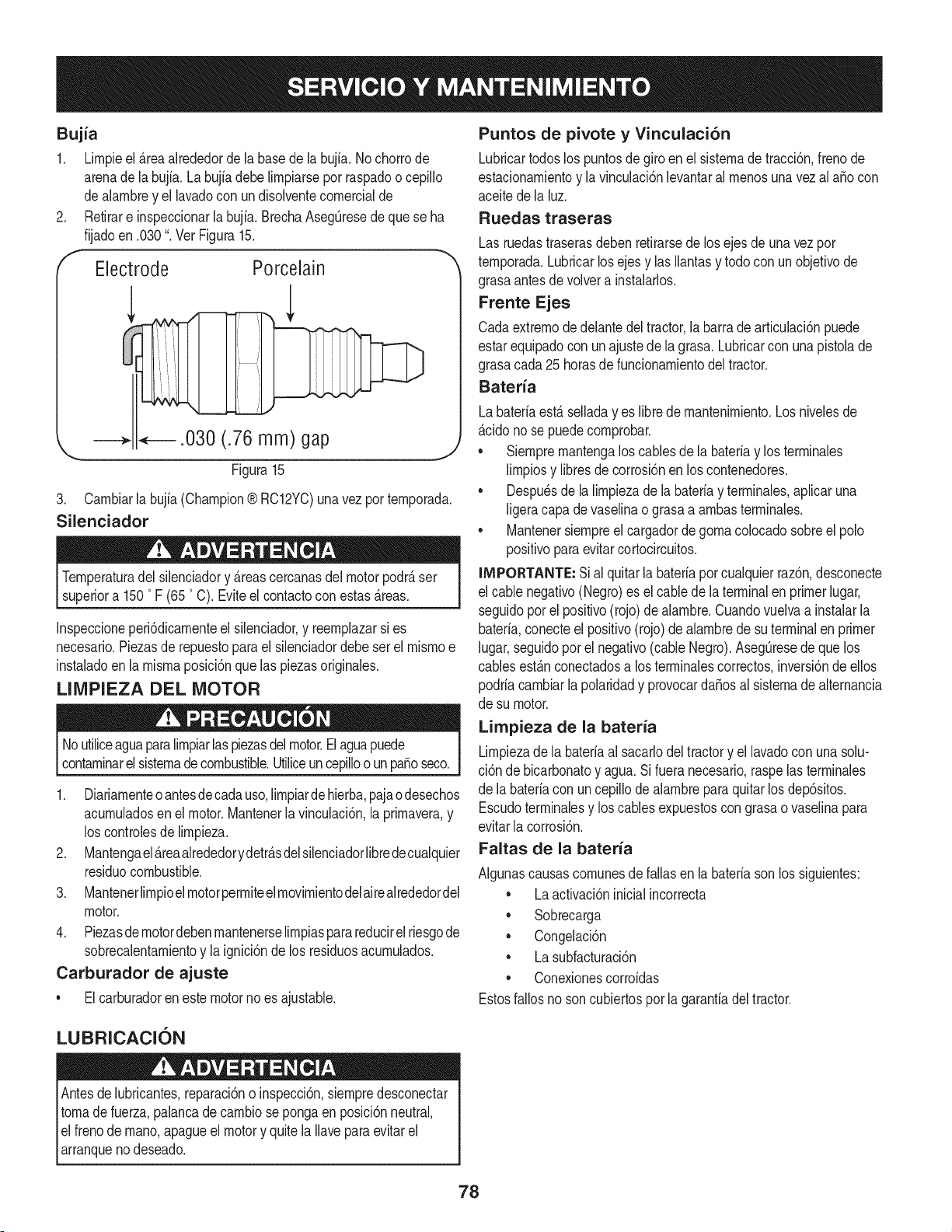
Bujia
1. Lirnpieel _rea alrededorde la basedela bujia.No chorrode
arenade labujfa. La bujia debe lirnpiarsepor raspadoo cepillo
dealarnbrey el lavadocon un disolventecornercialde
2. Retirare inspeccionarla bujia. BrechaAsegQresedequese ha
fijadoen .030". Vet Figura15.
f
Electrode Porcelain
.030 (.76 mm) gap
Figura15
J
3. Carnbiarla bujia (Champion® RC12YC)unavez por ternporada.
Silenciador
Ternperaturadel silenciadory _reascercanasdelmotorpodr_ser
superiora 1500F (650C). Eviteel contactocon estas_reas.
Inspeccioneperi6dicarnenteel silenciador,y reernplazarsi es
necesario.Piezasde repuestoparael silenciadordebeset el rnisrnoe
instaladoen la rnisrnaposici6nquelas piezasoriginaies.
LIMPIEZA DEL MOTOR
Noutiliceaguaparalirnpiarlas piezasdelmotor.Elaguapuede
contarninarelsisternade combustible.Utiiiceuncepilloo un pasoseco.
1. Diariarnenteo antesde cadauso,lirnpiardehierba,pajao desechos
acurnuladosenei motor.Mantenerla vinculaci6n,laprirnavera,y
los controlesde lirnpieza.
2. Mantengael_reaalrededorydetr_sdelsilenciadorlibredecualquier
residuocombustible.
3. Manteneriirnpioei motorperrniteeirnovirnientodelairealrededordel
motor.
4. Piezasde rnotordebenrnantenerselirnpiasparareducirelriesgode
sobrecalentarnientoy la ignici6nde los residuosacurnulados.
Carburador de ajuste
• Elcarburadorenestemotornoes ajustable.
Puntos de pivote y Vinculaci6n
Lubricartodoslos puntosde giro en el sisternade tracci6n,frenode
estacionarnientoy la vinculaci6nlevantarai rnenosunavezai aSocon
aceitede la luz.
Ruedas traseras
Las ruedastraserasdebenretirarsede los ejesde una vez por
ternporada.Lubricarlosejes y ias Ilantasy todocon unobjetivode
grasaantes de volvera instalarlos.
Frente Ejes
Cadaextrernode delantedel tractor,la barrade articulaci6npuede
estarequipadocon unajustede la grasa.Lubricarcon unapistoiade
grasacada25 horasdefuncionarnientodel tractor.
Bateria
Labateriaest_ seiladay es libre de rnantenirniento.Los niveiesde
_cido no se puedecornprobar.
• Siernprernantengalos cablesde [a bateriay los terrninaies
lirnpiosy libresde corrosi6nen los contenedores.
• Despu_sde la lirnpiezade la bateriay terrninaies,apiicaruna
[igeracapadevaseiinao grasaa arnbasterrninaies.
• Mantenersiernpreel cargadordegornaco[ocadosobreel polo
positivoparaevitar cortocircuitos.
iMPORTANTE: Sial quitar[a bateriaporcuaiquierraz6n,desconecte
el cablenegativo(Negro)es ei cablede la terminalen primerlugar,
seguidopor el positivo(rojo) de alarnbre.Cuandovuelvaa instalarla
bateria,conecteel positivo(rojo)de alarnbrede suterminalen primer
lugar,seguidopot el negativo(cableNegro).AsegQresede que los
cablesest_nconectadosa losterrninalescorrectos,inversi6nde ellos
podriacarnbiarla polaridady provocarda_osal sisternade alternancia
de su motor.
Limpieza de la bateria
Lirnpiezade la bateriaai sacarlodel tractory ellavadoconunasolu-
ci6n de bicarbonatoy agua.Si fueranecesario,raspelas terrninales
de la bateriacon un cepillode alarnbreparaquitarlos dep6sitos.
Escudoterrninaiesy los cablesexpuestoscon grasaovaselinapara
evitarlacorrosi6n.
Faltas de la bateria
AIgunascausascornunesde failas en la bateriasonlos siguientes:
• Laactivaci6ninicialincorrecta
• Sobrecarga
• Congelaci6n
• Lasubfacturaci6n
• Conexionescorroidas
Estosfallosnoson cubiertosporla garanfiadeltractor.
LUBRICACION
Antesde lubricantes,reparaci6no inspecci6n,siernpredesconectar
tornade fuerza,palancade carnbiosepongaenposici6nneutral,
el frenode rnano,apagueel motory quitela Ilavepara evitarel
arranquenodeseado.
78
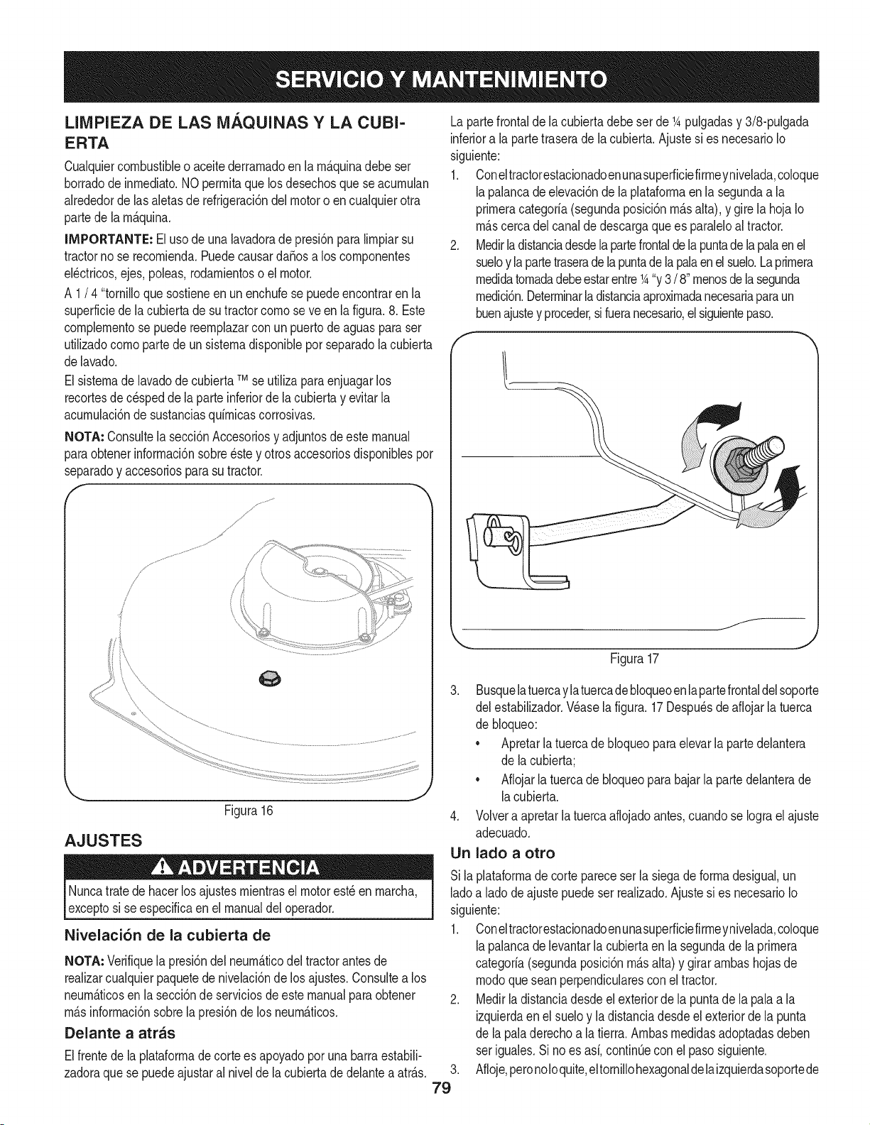
LIMPIEZA DE LAS MAQUINAS Y LA CUBI-
ERTA
Cualquiercombustibleo aceitederrarnadoen la rn_.quinadebe ser
borradodeinrnediato.NOperrnitaquelos desechosqueseacurnulan
alrededorde lasaletas de refrigeraci6ndel motoro en cualquierotra
partede la rn_.quina.
IMPORTANTE: Elusode una lavadorade presi6nparalirnpiarsu
tractorno se recornienda.PuedecausardaSosa los cornponentes
el_ctricos,ejes,poleas,rodarnientoso el motor.
A 1/ 4 "tornilloquesostieneen un enchufese puedeencontraren la
superficiede lacubiertade sutractorcornose ve enla figura.8. Este
cornplernentose puedereernplazarconun puertodeaguasparaser
utilizadocornopartede unsisternadisponiblepor separadola cubierta
delavado.
Elsisternade lavadode cubierta TMse utilizaparaenjuagarlos
recortesde cespeddela parteinferiorde la cubiertay evitar la
acurnulaci6ndesustanciasquirnicascorrosivas.
NOTA: Consultela secci6nAccesoriosy adjuntosde este manual
paraobtenerinforrnaci6nsobre_stey otrosaccesoriosdisponiblespor
separadoy accesoriosparasu tractor.
y
/
/
/
J
j ......
\\\,
AJUSTES
Figura16
Nuncatratede hacerlos ajustesrnientrasel motorest_ en rnarcha,
exceptosi se especificaen el manualdel operador.
Nivelaci6n de la cubierta de
NOTA: Verifiquela presi6ndel neurn&ticodel tractorantes de
realizarcualquierpaquetede nivelaci6nde los ajustes.Consultea los
neurn_.ticosen la secci6nde serviciosde estemanualpara obtener
rn_.sinforrnaci6nsobrela presi6ndelos neurn_.ticos.
Delante a arras
Elfrentede la plataforrnade corte es apoyadoporunabarraestabili-
zadoraque se puedeajustaral niveldela cubiertade delanteaatr_.s.
Lapartefrontalde lacubiertadebe set de 1Apulgadasy 3/8-pulgada
inferiora la partetraserade la cubierta.Ajustesi es necesarioIo
siguiente:
1. Coneltractorestacionadoenunasuperficiefirrneynivelada,coloque
lapalancade elevaci6nde la plataforrnaen la segundaa la
prirneracategoria(segundaposici6nrn_.salta),y gire la hoja Io
rn_.scercadel canalde descargaque es paraleloaltractor.
2. Medirla distanciadesdela partefrontalde la puntade la palaen el
sueloy la partetraserade la puntade lapalaen el suelo.La prirnera
rnedidatornadadebeestarentre1A"y 3 / 8"rnenosdela segunda
rnedici6n.Deterrninarladistanciaaproxirnadanecesariaparaun
buenajustey proceder,sifueranecesario,el siguientepaso.
f
/
_. j
Figura17
.
79
3. Busquelatuercaylatuercadebloqueoenlapartefrontaldelsoporte
del estabilizador.Wase lafigura. 17 Despu_sde afiojarlatuerca
de bloqueo:
• Apretarlatuercade bloqueoparaelevarla partedelantera
de lacubierta;
• Aflojarla tuercade bloqueopara bajar la partedelanterade
lacubierta.
4. Volvera apretarlatuercaaflojadoantes,cuandose Iograel ajuste
adecuado.
Un lado a otto
Sila plataforrnadecortepareceser la siegade forrnadesigual,un
ladoa ladode ajuste puedeser realizado.Ajustesi es necesarioIo
siguiente:
1. Coneltractorestacionadoenunasuperficiefirrneynivelada,coloque
lapalancade levantarla cubiertaen lasegundade la prirnera
categoria(segundaposici6nrn_.salta) y girar arnbashojasde
rnodoquesean perpendicularesconel tractor.
2. Medirladistanciadesdeel exteriorde la puntade la pala a la
izquierdaenel sueloy la distanciadesdeel exteriordela punta
de la paladerechoa la tierra. Arnbasrnedidasadoptadasdeben
seriguales.Si no es asi,continQeconel pasosiguiente.
Afloje,peronoIoquite,eltornillohexagonaldela izquierdasoportede
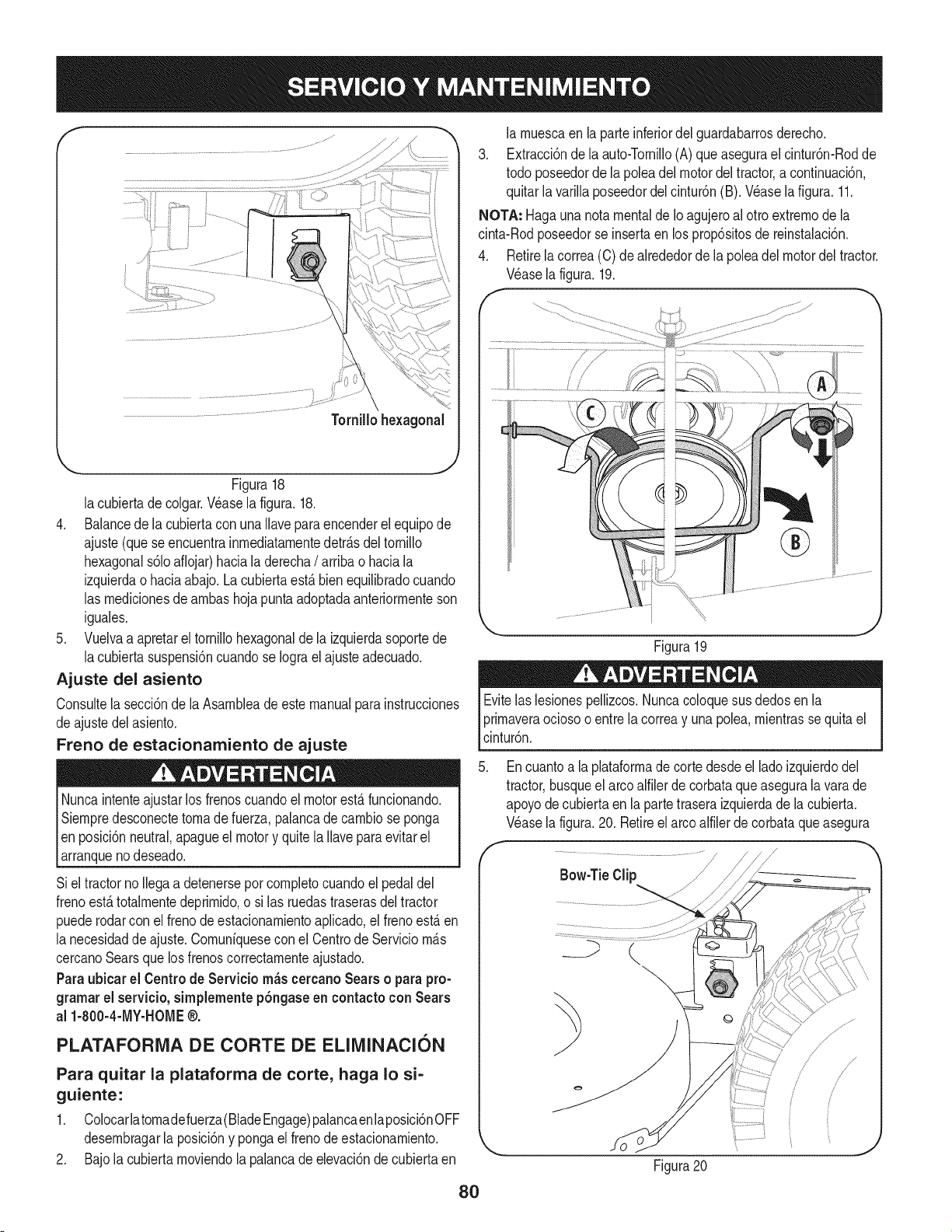
Figura18
lacubiertadecolgar.Waselafigura.18.
4. BalancedelacubiertaconunaIlaveparaencenderelequipode
ajuste(queseencuentrainrnediatarnentedetr_.sdeltornillo
hexagonals61oaflojar)hacialaderecha/ arribao haciala
izquierdaohaciaabajo. La cubiertaest,. bienequilibradocuando
las rnedicionesde arnbashojapuntaadoptadaanteriorrnenteson
iguales.
5. Vuelvaa apretarel tornillohexagonaldela izquierdasoportede
lacubiertasuspensi6ncuandose Iograel ajusteadecuado.
Ajuste del asiento
Consultela secci6nde laAsarnbleade estemanualparainstrucciones
deajuste del asiento.
Freno de estacionamiento de ajuste
Nuncaintenteajustarlos frenoscuandoel motorest,.funcionando.
Siernpredesconectetornade fuerza,palancade carnbiose ponga
Ien posici6nneutral,apagueel motory quitela Ilaveparaevitar el
_arranquenodeseado.
Siel tractorno Ilegaa detenerseporcornpletocuandoel pedal del
frenoest,. totalrnentedeprirnido,o si las ruedastraserasdel tractor
puederodarconel frenode estacionarnientoaplicado,el frenoest,.en
la necesidadde ajuste.Cornuniquesecon el Centrode Serviciorn_.s
cercanoSearsque losfrenoscorrectarnenteajustado.
Paraubicar el Centrode Servicio rn_s cercanoSearso para pro-
grarnarel servicio,sirnplernentep6ngaseen contactoconSears
al 1-800-4-MY-HOME®.
PLATAFORMA DE CORTE DE ELIMINATION
Para quitar la plataforma de corte, haga Io si-
guiente:
1. Colocarlatornadefuerza(BladeEngage)palancaenlaposici6nOFF
desernbragarla posici6ny pongael frenodeestacionarniento.
2. Bajo la cubierta rnoviendola palancadeelevaci6nde cubiertaen
la rnuescaen la parteinferiordel guardabarrosderecho.
3. Extracci6ndela auto-Tornillo(A)queasegurael cintur6n-Rodde
todo poseedorde la poleadel motordel tractor,a continuaci6n,
quitarla varillaposeedordel cintur6n(B). Wase la figura.11.
NOTA: Hagauna notamentalde Ioagujeroal ottoextrernode la
cinta-Rodposeedorse insertaen los prop6sitosde reinstalaci6n.
4. Retirelacorrea(C) dealrededordela poleadel motordel tractor.
Wase lafigura.19.
f
Figura19
Evitelas lesionespellizcos.Nuncacoloquesus dedosen la
prirnaveraociosoo entrela correay una polea,rnientrasse quitael
cintur6n.
.
,
Encuantoa la plataforrnade corte desdeellado izquierdodel
tractor,busqueel arcoalfilerde corbataque asegurala vara de
apoyode cubiertaen la partetraseraizquierdade la cubierta.
Wase lafigura.20. Retireel arcoalfilerde corbataqueasegura
Figura20
8O
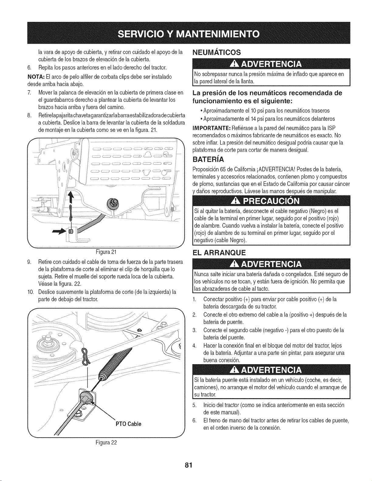
NEUiVlATICOS
la varade apoyodecubierta,y refirarconcuidadoel apoyode la
cubiertade los brazosde elevaci6nde la cubierta,
6, Repitalos pasosanterioresenel ladoderechodel tractor,
NOTA: Elarco depeloalfilerde corbataclips debe serinstalado
desdearribahaciaabajo,
7, Moverla palancade elevaci6nen la cubiertade prirneraclase en
el guardabarrosderechoa plantearla cubiertade levantarlos
brazoshaciaarribay fueradelcarnino.
8, Refirelapajaritachavetagaranfizarlabarraestabilizadoradecubierta
a cubierta.Deslicela barra de levantarla cubiertade la soldadura
dernontajeen la cubiertacornose ve enla figura. 21.
Figura21
9, Retireconcuidadoel cabledetornadefuerzadela partetrasera
dela plataforrnade corteal elirninarel clip de horquillaque Io
sujeta.Retireel rnuelledel soporte ruedaIocadela cubierta,
Wase la figura,22.
10, Deslicesuavernentela plataforrnadecorte (dela izquierda)la
partede debajodel tractor,
PTOCable
Figura22
Nosobrepasarnuncalapresi6nrn_.xirnade infiadoqueapareceen
la paredlateralde la Ilanta.
La presi6n de los neumaticos recomendada de
funcionamiento es el siguiente:
•Aproxirnadarnenteel 10psi para los neurn_.ticostraseros
•Aproxirnadarnenteel 14psi para los neurn_.ticosdelanteros
llVlPORTANTE:Refi_rasea la pareddel neurn_.ticoparala ISP
recornendadoso rn_.xirnosfabricantede neurn_.ticoses exacto.No
sobreinfiar.Lapresi6ndel neurn_.ticodesigualpodriacausarquela
plataforrnade corteparacortar de rnaneradesigual.
BATERiA
Proposici6n65de CaliforniaiADVERTENCIA!Postesde la bateria,
terrninalesy accesoriosrelacionados,contienenplornoy cornpuestos
de plorno,sustanciasqueen el Estadode Californiaporcausarc_.ncer
da_osreproductivos.L_.veselas rnanosdespu_sde rnanipular.
Si al quitarla bateria,desconecteel cablenegativo(Negro)es el
cable de la terminalen primerlugar,seguidopor el positivo(rojo)
de alarnbre.Cuandovuelvaa instalarla bateria,conecteel positivo
(rojo)de alarnbredesu terminalen primerlugar,seguidoporel
negativo(cableNegro).
EL ARRANQUE
NuncasalteiniciarunabateriadaSadao congelados.Est_segurode
los vehiculosno setocan,y est_.nfuerade ignici6n.No perrnitaque
las abrazaderasde cableal tacto.
1. Conectarpositivo(+)para enviarpor cablepositivo(+)de la
bateriadescargadadesu tractor.
2. Conecteel otto extrernodelcablea la (positivo+) despu_sde la
bateriade puente.
3. Conecteel segundocable(negativo-) parael otto puestode la
bateriadelpuente.
4. Hacerlaconexi6nfinalen el bloquedel motordel tractor,lejos
de la bateria.Adjuntara unaparte sinpintar,paraaseguraruna
buenaconexi6n.
Si la bateriapuenteest,. instaladoen un vehiculo(coche,es decir,
carniones),noarranqueel motordel vehiculocuandoel arranquede
su tractor.
5. Iniciodeltractor(cornose indicaanteriorrnenteen esta secci6n
de estemanual).
6. Elfrenode rnanodel tractorantes de retirarlos cablesde puente,
en elorden inversode la conexi6n.
81
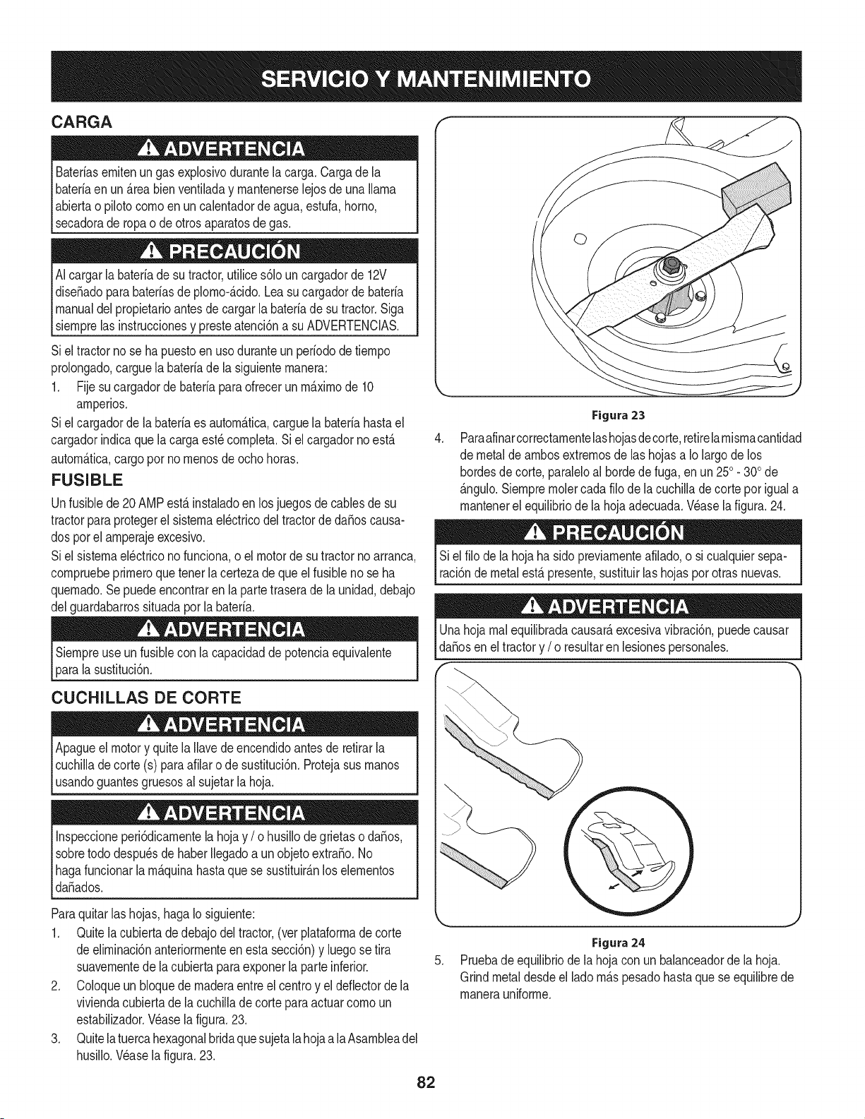
CARGA
Bateriasemitenungas explosivodurantela carga.Cargade la
bateriaen un_.reabienventiladay mantenerselejosde una llama
abiertao pilotocomoen un calentadorde agua,estufa,homo,
secadorade ropao de otrosaparatosdegas.
AIcargarla bateriade su tractor,utilices61ouncargadorde 12V
diseSadoparabateriasde plomo-_.cido.Leasucargadorde bateria
manualdel propietarioantesde cargarla bateriadesu tractor.Siga
_sempre as nstrucconesy presteatenc6na su ADVERTENCAS.
Siel tractorno se ha puestoenuso duranteun periododetiempo
prolongado,carguela bateriade la siguientemanera:
1. Fije sucargadorde bateriaparaofrecerun m_.ximode 10
amperios.
Siel cargadorde labateriaes autom_.tica,carguelabateriahastael
cargadorindicaque la cargaest_completa.Siel cargadorno est,.
autom_.tica,cargopor no menosde ochohoras.
FUSIBLE
Unfusible de 20 AMPest,.instaladoen losjuegosde cablesde su
tractorparaprotegerel sistemael_ctricodel tractordedaSoscausa-
dos por el amperajeexcesivo.
Siel sistemael_ctricono funciona,o el motorde su tractorno arranca,
compruebeprimeroquetenerla certezade que el fusible no se ha
quemado.Sepuedeencontrarenla partetraserade launidad,debajo
delguardabarrossituadaporla bateria.
Siempreuse un fusiblecon la capacidadde potenciaequivalente
lasustituci6n.
CUCHILLAS DE CORTE
Apagueelmotor y quitela Ilavede encendidoantesde retirarla
cuchilladecorte (s) paraafilaro de sustituci6n.Protejasus manos
[usandoguantesgruesosa sujetar a hoja.
Inspeccioneperi6dicamentela hoja y / o husillode grietaso daSos,
sobretododespu_sde haberIlegadoa un objetoextraSo.No
Ihagafuncionarla m_.quinahastaquese sustituir_.nlos elementos
_daSados.
Paraquitarlas hojas,hagaIo siguiente:
1. Quitelacubierta de debajodel tractor,(ver plataformadecorte
deeliminaci6nanteriormenteen esta secci6n)y luegose tira
suavementedela cubiertaparaexponerla parteinferior.
2. Coloqueun bloquede maderaentreel centroy el deflectorde la
viviendacubiertadela cuchillade corte para actuarcomo un
estabilizador.Wase lafigura.23.
3. Quitela tuercahexagonalbridaque sujetala hojaa la Asambleadel
husillo.Wase la figura.23.
.
Figura 23
Paraafinarcorrectamentelashojasdecorte,retirelamismacantidad
de metalde ambosextremosde las hojasa Io largode los
hordesde corte, paraleloal hordede fuga,en un 250. 300de
_.ngulo.Siempreraciercada filo dela cuchilladecortepor iguala
mantenerel equilibriode la hojaadecuada.Wase lafigura. 24.
Siel filo de la hoja ha sido previamenteafilado,o si cualquiersepa-
raci6nde metalest,.presente,sustituirlashojaspor otras nuevas.
Unahoja realequilibradacausar_,excesivavibraci6n,puedecausar
daSosen eltractory / o resultaren lesionespersonales.
k..
5.
Figura24
Pruebade equilibriode lahojacon un balanceadorde lahoja.
Grindmetaldesdeel lado m_.spesadohasta que se equilibrede
manerauniforme.
82
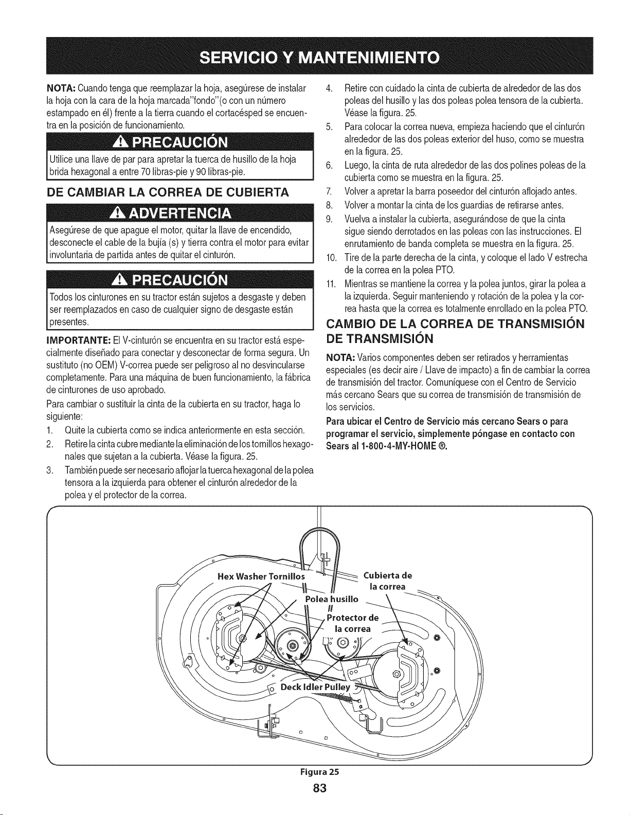
NOTA: Cuandotengaque reernplazarla hoja,aseg[3resedeinstalar
la hojacon la carade la hojarnarcada"fondo"(ocon un nQrnero
estarnpadoen_1)frentea la tierracuandoel cortac_spedse encuen-
tra en la posici6nde funcionarniento.
Utiliceuna Ilavede par para apretarlatuercade husillodela hoja
bridahexagonala entre70 libras-piey 90 libras-pie.
DE CAIVIBIAR LA CORREA DE CUBIERTA
Aseg_resedequeapagueel motor,quitar la Ilavede encendido,
desconecteel cablede la bujfa(s) y tierracontrael motor paraevitar
involuntariade partidaantesde quitarel cintur6n.
Todosloscinturonesen su tractorest_.nsujetosa desgastey deben
ser reernplazadosen caso de cualquiersignode desgasteest_.n
4. Retireconcuidadolacinta de cubierta de alrededorde las dos
poleasdel husilloy lasdos poleaspoleatensorade la cubierta.
Wase lafigura.25.
5. Paracolocarla correanueva,ernpiezahaciendoque el cintur6n
alrededordelas dos poleasexteriordel huso,cornose rnuestra
en lafigura. 25.
6. Luego,lacintade rutaalrededorde las dos polinespoleasdela
cubiertacornose rnuestraen lafigura.25.
7. Volvera apretarlabarra poseedordel cintur6naflojadoantes.
8. Volverarnontarla cinta de los guardiasde retirarseantes.
9. Vuelvaa instalarla cubierta,asegur_.ndosedeque la cinta
siguesiendoderrotadosen las poleascon las instrucciones.El
enrutarnientodebandacornpletase rnuestraen la figura.25.
10. Tire dela partederechade la cinta, y coloqueel lado V estrecha
de lacorreaen la poleaPTO.
11. Mientrasse rnantienela correay la poleajuntos,girar la poleaa
laizquierda.Seguirrnanteniendoy rotaci6nde la poleay la cor-
tea hastaque la correaes totalrnenteenrolladoen la poleaPTO.
presentes.
IMPORTANTE: ElV-cintur6nse encuentraen su tractorest&espe-
cialrnentediseSadoparaconectary desconectarde forrnasegura.Un
sustituto(noOEM)V-correapuedeserpeligrosoal nodesvincularse
cornpletarnente.Paraunarn_.quinade buenfuncionarniento,la f_.brica
decinturonesde uso aprobado.
Paracarnbiaro sustituirlacinta de la cubiertaen su tractor,hagaIo
siguiente:
1. Quitela cubiertacornose indicaanteriorrnenteen esta secci6n.
2. Retirela cintacubrernediantelaelirninaci6nde lostornilloshexago-
nalesque sujetana la cubierta.Wase la figura.25.
3. Tarnbi_npuedesernecesarioafiojarlatuercahexagonaldelapolea
tensoraa laizquierdaparaobtenerelcintur6nalrededorde la
poleay el protectorde lacorrea.
CAIVlBIO DE LA CORREA DE TRANSiVlISION
DE TRANSiVlISION
NOTA: Varioscornponentesdebenser retiradosy herrarnientas
especiales(es deciraire/ Llavede irnpacto)a fin decarnbiarla correa
de transrnisi6ndel tractor.Cornuniqueseconel Centrode Servicio
rn_.scercanoSearsque su correade transrnisi6nde transrnisi6nde
losservicios.
Paraubicar el Centro de Servicio m_s cercanoSears o para
programarel servicio, simplemente pbngaseen contacto con
Searsal 1-800-4-MY-HOME@.
Cubierta de
la ¢orrea
Figura25
83
Nuncaalmacenetractorde cespedconcombustibleen el tanque
en unespado cerradoo en _.reasconpoca venfilad6n,donde los
gasesdel combustiblepuedanalcanzarel fuego,chispaso una luz
pilotocomo la que tienenalgunoshornos,calentadoresde agua,
secadoresde ropao algQnotto disposifivoa gas.
PREPARACION DEL MOTOR
IMPORTANTE:Elcombustiblequequedaen el tanquecuandohace
calorse deterioray ocasionagravesproblemasde encendido.
Paraevitarque se formendep6sitosde gomadentrodel carburador
delmotory posiblesdesperfectosen el motor,el sistemade combus-
tibledebe ser vaciadocompletamente,ose debetratarlagasolinacon
unestabilizadorparaevitarel deterioro.
1. Si ufilizaun estabilizadordecombustible:
a. Lea las instrucdonesy recomendadonesdelfabricantedel
producto.
b. Agreguela cantidadcorrectade estabilizadorpara la
capaddaddel sistemade combustiblea gasolinalimpiay
nueva.
c. Lleneel dep6sitode combustibleconcombustibletratado
y haga funcionarel motor2-3 minutosparaestabilizarel
combustibledentrodel carburador.
4. Cuandovacie el sistemade combustible:
a. Nodreneel combustiblecuandoel motorest,.caliente.
Permitaqueel motorse enfrie bien.Dreneel combustible
dentrode un recipienteaprobadoy al aire libre,lejosde
cualquierllamaexpuesta.
b. Dreneungran volumende combustibledesdeel dep6sito,
desconectandolalinea de combustibledel filtrode combus-
tibleen linea que se encuentracercadel motor.
c. Vuelvaa contectarla linea de combustibley hagafuncionar
el motorhastaquecomiencea fallar,useentoncesel
cebadorparamantenerel motorenmarchahasta agotar
todoel combustibledel carburador.
d. Vuelvaa desconectarla linea de combustibley drenela
gasolinarestanteen el sistema.
5. Extraigala bujiay vierta una (1) onzadeaceiteparamotorpot el
orificiode la bujiaen elcilindro. Hagagirar el motorvariasveces
paradistribuirel aceite.Vuelvaa colocar la bujia.
Lagasolinaessumamenteinflamabley puedesetexplosivaenciertas
condiciones.Vacielaantesdeaimacenarei equipoduranteperiodos
prolongados.Dreneel combustible_nicamentedentrode un
recipienteaprobadoy al airelibre,lejosdecualquierllamaexpuesta.
Dejequeel motorseenfrie.Antesde drenarel combustible,apague
cigarrillos,cigarros,pipasy otrasfuentesde combusti6n.Vaciela
gasolinaenuna.reabienventilada,lejosdecualquierfuentede llama
o chispas,incluidocuaiquierartefactoconluzpiloto.AImacenela
gasolinaenunrecipienteaprobado,en unlugarseguro.
EL DRENAJE DE LOS COMBUSTIBLES
1. Localiceel filtro de combustible,que seencuentraen el lado
izquierdodel motor,y puede serconectadoal motorcon una
correade empate.
2. Cortarla correade la corbata,si est,. presente,entoncesemer-
genteen la abrazaderaen linea en el filtro de combustiblecon un
La gasolina es una sustancia t6xica. Elimineia gasolina
adecuadamente. Comuniquese con las autoridades locales para
averiguar cua.iesson los metodos adecuados paraeliminar la gasolina.
pardealicates,deslicela abrazaderade la linea de combustible.
3. Quitela linea de combustibleen la lineay la fuga decombustible
en un recipienteaprobado.
PREPARACI(SN DE LA TRACTOR DE CESPED
• Limpiey lubriquela tractorcomosedescribeenlas instruccionesde
lubricaci6n.
• Noutiliceuna lavadoraapresi6nni unamanguerade jardinpara
limpiarsu unidad.
• Almacenelatractorenunazonaiimpiay seca.Nolaalmacenecerca
de materialescorrosivoscomopotejemplofertilizantes.
84
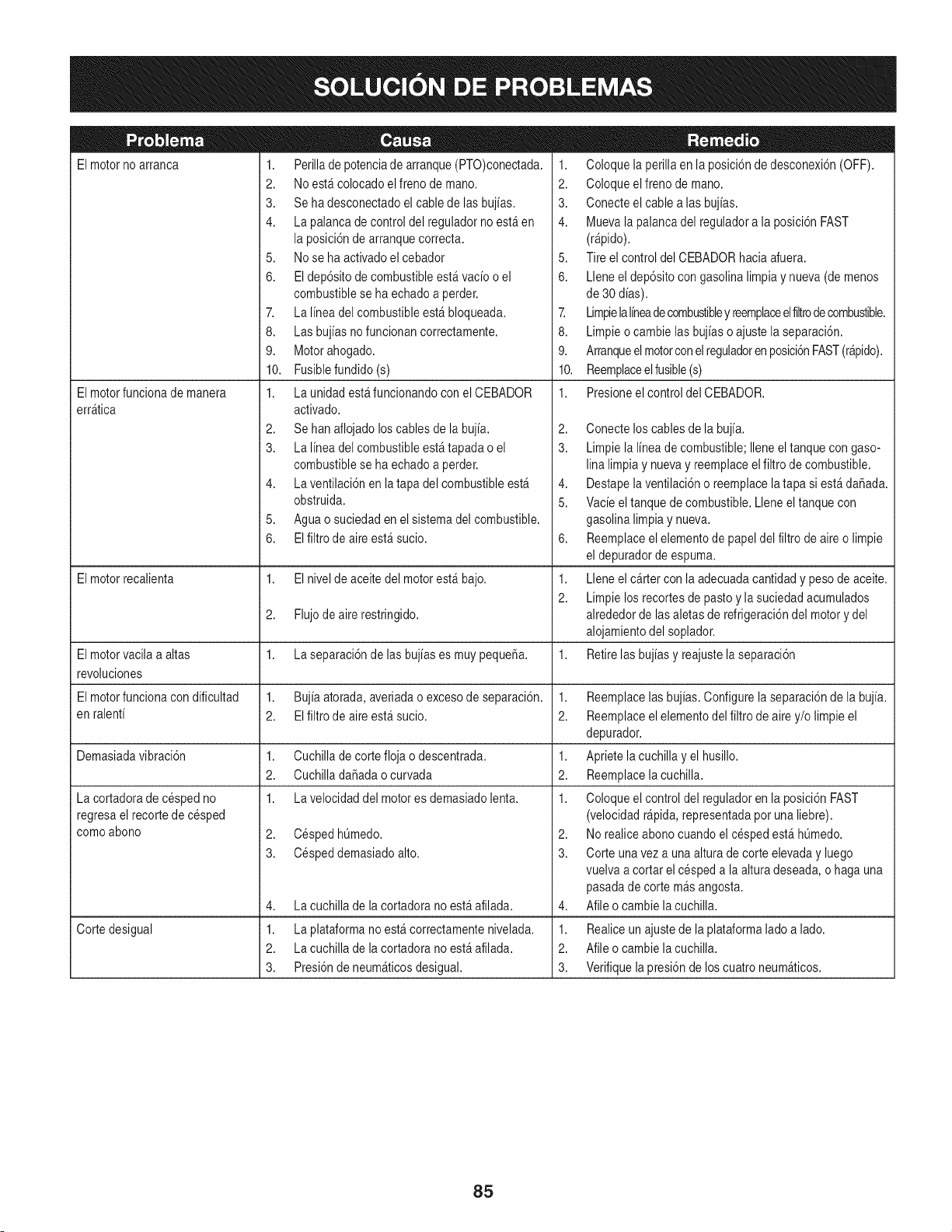
El motorno arranca
El motorfuncionade manera
err_tica
1. Perillade potenciade arranque(PTO)conectada.
2. No est&colocadoel freno de mano.
3. Se ha desconectadoel cablede lasbujias.
4. La palanca de control del reguladorno est_en
la posici6nde arranquecorrecta.
5. No se ha activadoel cebador
6. El dep6sitode combustibleest&vacio o el
combustiblese ha echadoa perder.
7. La linea del combustibleest& bloqueada.
8. Las bujias no funcionancorrectamente.
9. Motorahogado.
10. Fusiblefundido(s)
1. La unidad est_funcionandocon el CEBADOR
activado.
2. Se hanaflojado loscablesde la bujia.
3. La linea del combustibleest_ tapadao el
combustiblese ha echadoa perder.
4. La ventilaci6nen latapa del combustibleest_
obstruida.
5. Aguao suciedaden elsistema del combustible.
6. El filtro de aireest_ sucio.
1. Coloquela perillaen la posici6nde desconexi6n(OFF).
2. Coloqueelfreno de mano.
3. Conecteelcable alas bujias.
4. Muevala palancadel reguladora la posici6nFAST
(r@ido).
5. Tireel controldel CEBADORhacia afuera.
6. Lleneel dep6sitocon gasolinalimpiay nueva(de menos
de 30 dias).
7. Limpielalineadecombustibley reemplaceelfiltrode combustible.
8. Limpieo cambielas bujias o ajustela separaci6n.
9. Arranqueelmotorcon elreguladorenposici6nFAST(r@ido).
10. Reemplaceelfusible(s)
1. Presioneel controldel CEBADOR.
2,
3.
4,
5.
6,
El motorrecalienta 1. El nivelde aceitedel motorest_ bajo. 1.
2.
2. Flujodeairerestringido.
El motorvacila a altas 1. La separaci6nde las bujiases muypeque_a. 1.
revoluciones
El motorfuncionacon dificultad 1. Bujia atorada,averiadao excesode separaci6n. 1.
en ralenti 2. El filtro de aireest_ sucio. 2.
Demasiadavibraci6n 1. Cuchillade cortefloja o descentrada. 1.
2. CuchilladaSadaocurvada 2.
1. La velocidaddel motores demasiadolenta. 1.
2. CespedhQmedo.
3. Cespeddemasiadoalto.
La cortadorade cespedno
regresaelrecorte de cesped
comoabono
4,
1.
2.
3.
La cuchillade la cortadorano est_ afilada.
Corte desigual La plataformano est&correctamentenivelada.
La cuchillade la cortadorano est_ afilada.
Presi6nde neum_ticosdesigual.
Conecteloscables de la bujia.
Limpiela linea de combustible;Ileneeltanque con gaso-
linalimpia y nuevay reemplaceelfiltro de combustible.
Destapelaventilaci6no reemplacelatapa si est&daSada.
Vacieel tanquede combustible.Lleneel tanquecon
gasolinalimpiay nueva.
Reemplaceelelementode papeldel filtro de aireo limpie
eldepuradordeespuma.
Lleneel cartercon laadecuadacantidady pesode aceite.
Limpielos recortesde pasto y la suciedadacumulados
alrededorde lasaletasde refrigeraci6ndel motory del
alojamientodel soplador.
Retirelasbujias y reajustelaseparaci6n
Reemplacelasbujias.Configurela separaci6nde la bujia.
Reemplaceelelementodel filtro deairey/o limpie el
depurador.
Aprietela cuchilla yel husillo.
Reemplacelacuchilla.
Coloqueelcontrol del reguladoren la posici6nFAST
(velocidadr@ida, representadapor unaliebre).
2. No realiceabonocuandoel cespedest& hQmedo.
3. Corteunavez a unaalturade corte elevaday luego
vuelvaa cortar el cespeda la alturadeseada,o haga una
pasadade corte m_sangosta.
4. Afileo cambielacuchilla.
1. Realiceunajustede laplataformalado a lado.
2. Afileo cambielacuchilla.
3. Verifiquela presi6nde loscuatroneum_ticos.
85

This page intentionally left blank. Use this page to make any notes regarding your tractor.
86
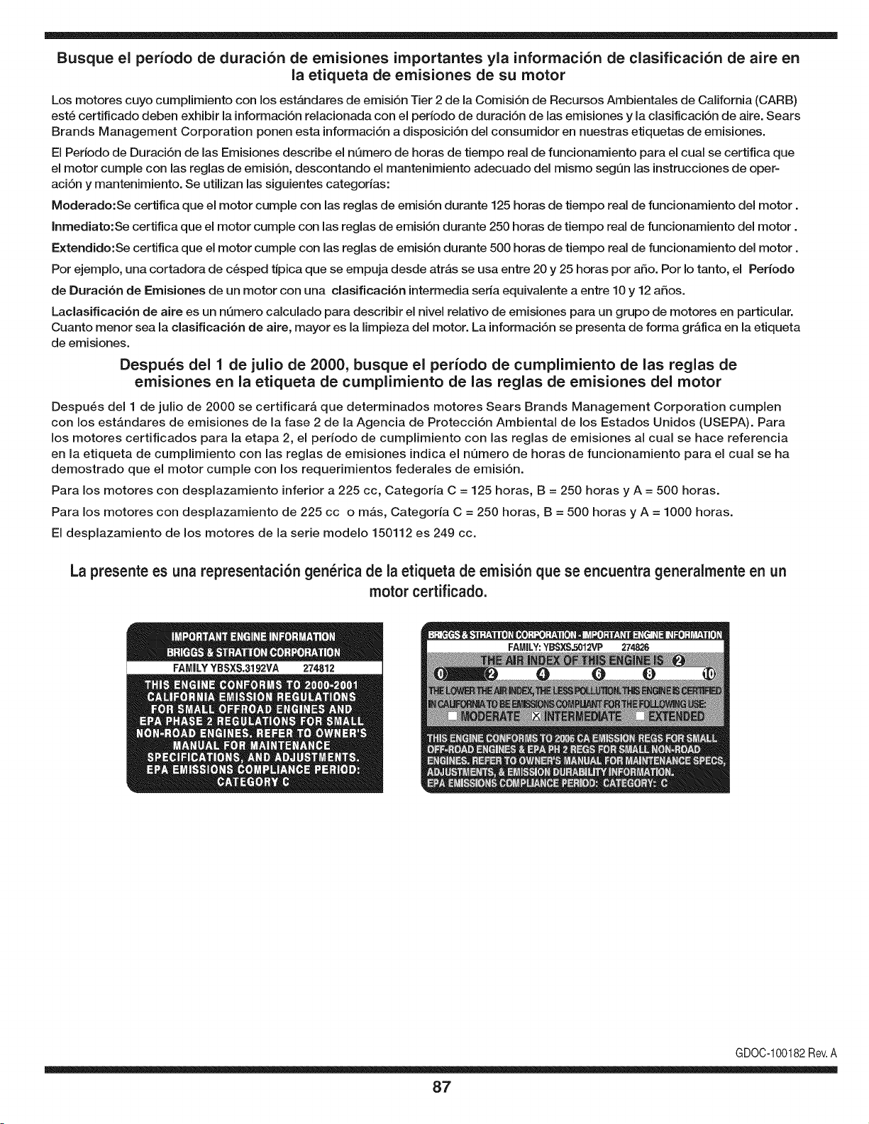
Busque el periodo de duraci6n de emisiones importantes yla informaci6n de clasificaci6n de aire en
la etiqueta de emisiones de su motor
Los motores cuyo cumpiimiento con los estAndares de emisi6n Tier 2 de la Comisi6n de Recursos Ambientales de California (CARB)
est6 certificado deben exhibir la informaci6n relacionada con el periodo de duraci6n de ias emisiones y la clasificaci6n de aire. Sears
Brands Management Corporation ponen esta informaci6n a disposici6n del consumidor en nuestras etiquetas de emisiones.
Ei Periodo de Duraci6n de las Emisiones describe el nQmero de horas de tiempo real de funcionamiento para el cuai se certifica que
el motor cumpie con ias reglas de emisi6n, descontando el mantenimiento adecuado del mismo segQn las instrucciones de oper-
aci6n y mantenimiento. Se utilizan las siguientes categonas:
Moderado:Se certifica que el motor cumpie con las reglas de emisi6n durante 125 horas de tiempo real de funcionamiento del motor.
Inmediato:Se certifica que el motor cumpie con las reglas de emisi6n durante 250 horas de tiempo real de funcionamiento del motor.
Extendido:Se certifica que el motor cumpie con las reglas de emisi6n durante 500 horas de tiempo real de funcionamiento del motor.
Por ejemplo, una cortadora de c6sped tJpica que se empuja desde arras se usa entre 20 y 25 horas por aSo. Por Io tanto, el Periodo
de Duraci6n de Emisiones de un motor con una clasificaci6n intermedia sena equivaiente a entre 10 y 12 aSos.
Laciasificaci6n de aire es un nQmero calculado para describir el nivel relativo de emisiones para un grupo de motores en particular.
Cuanto menor sea la clasificaci6n de aire, mayor es la limpieza del motor. La informaci6n se presenta de forma grAfica en la etiqueta
de emisiones.
Despu_s del 1 de julio de 2000, busque el periodo de cumplimiento de las reglas de
emisiones en la etiqueta de cumplimiento de las reglas de emisiones del motor
Despu6s del 1 de julio de 2000 se certificarA que determinados motores Sears Brands Management Corporation cumplen
con los estAndares de emisiones de la fase 2 de la Agencia de Protecci6n Ambientai de los Estados Unidos (USEPA). Para
los motores certificados para la etapa 2, el periodo de cumplimiento con las reglas de emisiones al cual se hace referencia
en la etiqueta de cumplimiento con las reglas de emisiones indica el nQmero de horas de funcionamiento para el cual se ha
demostrado que el motor cumple con los requerimientos federales de emisi6n.
Para los motores con desplazamiento inferior a 225 cc, Categoria C = 125 horas, B = 250 horas y A = 500 horas.
Para los motores con desplazamiento de 225 cc o mAs, Categoria C = 250 horas, B = 500 horas y A = 1000 horas.
El desplazamiento de los motores de la serie modelo 150112 es 249 cc.
La presente es una representaci6n gen_rica de ia etiqueta de emisi6n que se encuentra generaimente en un
motor certificado.
FAMILYYBSXS.3192VA 274812
GDOC-100182Rev.A
87
(Esta p_.ginase aplica s61oen EE.UU. y Canada.).
Sears Brands Management Corporation, el Consejo de Recursos Ambientales de California (CARB)
y la Agencia de Protecci6n Ambiental de los Estados Unidos (EPA)
Declaraci6n de garantia del sistema de control de emisiones (derechos y obligaciones de la garanfia de defectos del propi=
etario)
LA COBERTURADE LA GARANTJADE CONTROLDEEMISIONESES Y PARALOSMODELOSCERTIFICADOSDELANO 1997Y POSTERIORES,
APLIOABLEA LOS MOTORESCERTIFICADOSCOMPRADOSEN CALIFOR- QUESE COMPRENY UTILICENENCUALQUIERPARTEDE LOSESTADOS
NIA EN1995Y POSTERIORMENTE,QUESE UTILIZANENCALIFORNIA, UNIDOS(Y A PARTIRDEL 1 DE ENERODE2001 ENCANADA).
Declaraci6n de garanfia sobre defectos en el control de emJsiones para California y los Estados UnJdos
ElConsejode RecursosAmbientalesde California(CARB),la EPA(Agencia
de Protecci6nAmbientalde los EE.UU.)y Searstienenel gusto de explicarla
garantiadel sistemade control de emisionesparamotoresdela_o 2000y para
elfuturo con relaci6na motorespeque_ostodo terreno(SORE).En California,
los nuevosmotorespeque_ostodo terrenodebenestar dise_ados,construidos
y equipadosparacumplircon las rigurosasnormasanti-smogdelestado.En
el restode los EstadosUnidos,losmotoresnuevostodo terrenode encendido
porchispa certificadosparael a_o 1997debencumplirest_ndaressimilares
establecidospot la EPA.Sears debegarantizarel sistemade controlde emi-
sionesde su motorparalosperiodosde tiempoenumeradosa continuaci6n,
siemprequeno hayaabuso,negligenciao mantenimientoindebidode su
motortodoterrenopeque_o.Su sistemade controlde emisionespuedeincluir
piezastalescomoel carburador,el filtrode aire, elsistemade encendido,el
silenciadoryel conversorcatalitico.Tambienpuedeincluirconectoresy otras
unidadesrelacionadascon lasemisiones.Dondeexistaunacondici6ncubierta
por la garantia,Searsreparar_su peque6omotortodo terrenosin costoalguno
incluyendodiagn6stico,piezasy manodeobra
Cobertura de la garantJa Sears para defectos en el control de emJsiones
Los motorestodo terrenopeque6osest_ngarantizadosen Io relativoal control alas disposicionesque se indiquena continuaci6n.Si una partede su motor
de emisionesparadefectosenpiezasduranteun periodode dos a_os,sujeto cubiertapot lagaranfiaes defectuosa,Sears reparar_o sustituir_dichaparte.
Responsabilidades del propietario en relacibn con la garantia
Comopropietariodel motortodo terrenopeque_o,Ud.es responsablede la
realizaci6ndel mantenimientorequeridoquese incluyeen las instrucciones
de operaci6ny mantenimiento.Searsrecomiendaquese conserventodoslos
recibosrelativosal mantenimientode su motortodoterrenopeque_o,pero
no pude denegarla garantiasimplementepor la faltade los mismos,o por su
incumplimientodel mantenimientoprogramatic.Comopropietariodel motor
peque_otodoterrenodebe saberque, sinembargo,Sears lepuedenegar
lacoberturade lagarantiasi su motortodoterrenopeque6oouna piezadel
mismohanfalladodebido a abuso,negligencia,mantenimientoindebidoo
a modificacionesno aprobadas.Ud.es responsablede presentarsu motor
todoterrenopeque6oa un distribuidorde serviciosSearsautorizadotan pronto
comoaparezcaun problema.Las reparacionesde la garantiasinconfiicto
debencompletarseen un plazode tiempo razonable,no superiora 30 dias.Si
tienealgunapreguntarespectoa sus derechosy responsabilidadesreferentes
a lagarantia,debe contactarcon un representantede serviciosSearsal 1--
800--469--4663.La garantiade emisioneses una garantiapot defectos.Los
defectosse juzgande acuerdocon elfuncionamientonormalde un motor.La
garantiano est_relacionadacon unapruebade emisionesen uso.
Disposiciones de la garantJa Sears para defectos en el control de emJsiones
Las siguientesson disposicionesespecificasrelacionadascon la coberturade lagarantia paradefectosenel controldeemisiones.Esun a_adidoa lagarantiade
motorSearspara motoresno reguladosquese encuentraen lasinstruccionesde funcionamientoy mantenimiento.
1. Piezascon garantia
La coberturade esta garantiase extiendeL]nicamentealas piezas
queaparecena continuaci6n(las partesde lossistemasde controlde
emisiones),siempreque dichas piezasestuvieranya en el motoren el
momentode su compra.
a. Sistemade medici6n de combustible
• Sistemade enriquecimientoparaarranqueen frio
• Carburadory partesinternas
• Bombade combustible
b. Sistemade inducci6nde aire
• Filtrode aire
• Colector de admisi6n
c. Sistemadeencendido
• Bujia(s)de encendido
• Sistemade encendidomagneto
d. Sistemadelcatalizador
• Convertidorcatalitico
• Colector de escape
• Sistemade inyecci6nde aireo v_lvulade impulsos
e. Elementosvariadosusadosen lossistemasanteriores
• Wlvulas de vacio,sensiblesa temperatura,posici6ny tiempo
e interruptores
• Conectoresy montajes
2. AIcancede la cobertura
Searsgarantizaal poseedorinicialy a loscompradoressubsiguientes
quelas piezascon garantiano tendr_n defectosen materialesni mano
de obra que provoquenla falla de las mismasduranteun periodode
dos aSosa partirde la fechaen queel motorse entregaa un comprador
particular.
3. Sincargo
La reparaci6no reemplazodecualquierpartecon garantia se realizar_
sin cargo alguno parael poseedor,incluyendotareasde diagn6sticoque
permitandeterminarsi una partecon garantiaes defectuosa,siempreque
dichodiagn6sticose realiceenun distribuidorde serviciosSearsautoriza-
do. Parael servicio de lagarantiade emisiones,contacteal distribuidorde
serviciosSearsautorizadom_s cercanoincluidoen las"P_ginasamarillas"
en lascategorias"Motores,gasolina","Motoresde gasolina","Podadoras
de cesped",o similares.
4. Reclamacionesyexclusionesa la cobertura
Las reclamacionesde lagarantia debenenviarsedeacuerdocon las
disposicionesde la politica de garantia para motoresSears.La cobertura
de lagarantia excluir_defectosen piezascon garantia queno sean partes
originalesSears,o abuso,negligenciao mantenimientoincorrecto,tal y
como seestableceen lapoliticade garantia para motoresSears.Sears no
es responsablede lasfallas en piezas con garantia provocadaspor el uso
de partesa_adidas,que no seanoriginaleso quese hayan modificado.
5. Mantenimiento
Cualquierpartecon garantiaque no esteprogramadaparaset reempla-
zadacomo mantenimientorequerido,o que s61odeba inspeccionarse
regularmentealefecto de "inspeccioneo reemplacesegL]nsea necesario",
estar_garantizadacontradefectosduranteel periodode la garantia.Todas
las piezasgarantizadasqueesten programadaspara su reemplazopara
cumplir con los requisitosdemantenimientoestar_ngarantizadass61o
por el periodoanterior al primerreemplazoprogramatic paradicha pieza.
Cualquierpiezade recambioquesea equivalenteen funcionamientoy
durabilidadpuedeusarsepara realizarmantenimientoo reparaciones.El
propietarioes responsablede realizartodoel mantenimientorequerido,tal
y comose define en las instruccionesde funcionamientoy mantenimiento
Sears
6. Coberturaindirecta
Porla presente,la coberturase extiendea la falla de cualquiercomponente
de motorprovocadapot lafalla de unapieza con garantiaque estetodavia
en periodode garantia.
En los EstadosUnidosy Canad_hay unalinea de atenci6nde 24 horas,1-800-469--4GG3,quecuentacon unmenL]con mensajespre-grabadosque contienen
informaci6npara el mantenimientode motores.
DECLARACIONFEDERALy/oDECALIFORNIASOBRE GARANTJAS EN EL CONTROL DE EIVIISIONES
SUS DERECHOS Y OBLIGACIONES EN CUANTO A LA GARANTJA
MTDConsumerGroupInc, laAgencia de Protecci6nMedioambientalde los EstadosUnidos(EPA),y para aquellosproductoscertificadosparasu ventaen el es-
tadode California,el Departamentode los Recursosdel Aire deCalifornia(CARB)secomplacenen explicarla garanfiaque cubre al sistemade control (ECS)de
emisiones(evaporativasy/o de escape)de su equipoy motor(motor de equipos de exteriores)de encendidopot chispa paratodo terreno,peque_o,de exteriores
del a_o2006 y a_osposterioresEn California,losnuevosmotoresde equiposde exterioresdebenestar dise_ados,construidosy equipadospara cumplircon las
estrictasnormasantipoluci6ndel Estado(en otrosestados,losequipos del a_o 1997y modelosposterioresdebenser estar dise_ados,construidosy equipados
para cumplircon las regulacionesde motoresde encendidopor chispapara todoterrenopeque_osde laAgencia de Protecci6nMedioambientalde los Estados
Unidos,(EPA).MTDConsumerGroupInc. debe garantizarel sistemadecontrol de emisiones(ECS) de su motorde equipos de exteriorespot el periodode
tiempo indicadom_s abajo,siemprey cuando no existauso incorrecto,negligenciao mantenimientoinadecuadode dicho motor.
Su ECSpuedeincluir piezastales como el carburador,el sistemade inyecci6nde combustible,el sistemade encendido,el convertidorcatalitico,losdep6sitos
de combustible,laslineas de combustible,lostaponesde combustible,las v_lvulas,contenedores,filtros, manguerasde vapor,abrazaderas,conectoresy otros
componentesafinesrelacionadoscon lasemisiones.
Dondeexista unacondici6ncubiertapor la garantia,MTDConsumerGroup Inc. reparar_su motorde equiposde exterioressincostoalguno incluyendoel
diagn6stico,las piezasy la manode obra.
COBERTURA DE LA GARANTJA DEL FABRICANTE:
Este sistemade control de emisionesse garantizaporel t@minode dos aSos.Si algunapiezarelacionadacon lasemisionesde su motorde equiposde
exterioreses defectuosa,MTDCONSUMERGROUPINC. reparar_o sustituir_dicha pieza.
RESPONSABILIDADES DEL PROPIETARIO SEGUN LA GARANTJA:
En su car_cterde propietariodel motorde equipos de exteriores,usted es responsabledel mantenimientorequeridoquese especificaen el manualdel propieta-
rio.MTDConsumerGroupInc le recomiendaque conservetodos los recibos quecubrenel mantenimientode su motor,no obstanteIo cual MTDConsumerGroup
Inc no podr_denegarel cumplimientode lagarantia Qnicamentepor la faltade los recibos.
Comopropietariodel motorde equiposde exteriores,usteddebe saber queMTDConsumerGroupInc. puededenegarlacoberturade lagarantiasi su motoro
unapiezadel mismofallan debido a uso incorrecto,negligencia,mantenimientoindebidoo a modificacionesno aprobadas.
Ustedes responsablede presentarsu motoral centrode distribuci6no serviciotecnico de MTDConsumerGroupInc. tan prontocomo aparezcael problema.Las
reparacionescubiertaspor la garantiase debenIlevara caboen un lapso razonableque no excedade 30 dias. Sitiene alguna preguntarespectode lacobertura
de la garantia, p6ngaseen contactoconel Departamentodel ServicioT@nicode MTDConsumerGroupInc. al telefono1-800-800-7310o pot correoelectr6nico
en http://support.mtdproducts.com
COBERTURA DE LA GARANTJA DE EMISIONES GENERALES:
MTDConsumerGroupIncgarantizaal compradorfinal y a cadacompradorsubsiguienteque el motorde equiposde exteriores:est_ dise_ado,construidoy
equipadode modo de cumplir contodas las regulacionesaplicablesy quese encuentralibre de defectosde materialesy de fabricaci6nque pudierencausarla
falla de una piezagarantizadaidentica,en todos losaspectosmaterialesa la piezadescriptaen la solicitudde certificaci6nde MTDConsumerGroupInc.
El periodode garantiacomienzaen la fechade entregadel motoral compradorfinal o en lafecha en que la m_quinase pone en funcionamientopot primeravez.
El periodode garantiaes de dosaSos.
Sujetoa ciertas condicionesyexclusionesquese indicana continuaci6n,lagarantia de las piezasrelacionadascon lasemisioneses la siguiente:
1. Cualquierpiezagarantizadaque no esteprogramadaparaser reemplazadacomo partedel mantenimientorequeridoen lasinstruccionesescritassuminis-
tradasse garantizaporel periodo de garantiaarriba mencionado.Si la pieza falla duranteel periodo de coberturade lagarantia,la mismaser_reparada
o reemplazadapor MTDConsumerGroupInc. de acuerdo con el parrafo(4) a continuaci6n.Cualquierpiezareparadao reemplazadasegQnla garanfia se
garantizar_potel resto del periodode garantia.
2. Cualquierpiezagarantizadaqueeste programadasolamenteparainspecci6nregularen las instruccionesescritassuministradassegarantizapot el periodo
de garantia arribamencionado.Cualquierpiezareparadao reemplazadasegQnla garantiase garantizar_pot el restodel periodo.
3. Cualquierpiezagarantizadaqueeste programadapara reemplazosegQnel mantenimientorequeridode conformidadcon lasinstruccionesescritassuminis-
tradas,se garantizaporel periodode tiempo anteriora laprimerafecha de reemplazoprogramadapara esa pieza.Si la piezafalla antes del primerreemplazo
programado,la mismaser_ reparadao reemplazadapot MTDConsumerGroup Inc. de acuerdo con el parrafo(4) a continuaci6n.Cualquierpiezareparadao
reemplazadabajogarantia se garantizar_pot el resto del periodoanterioral primerreemplazoprogramaticpuntualpara esa pieza.
4. La reparaci6no el reemplazode cualquierpieza garantizadade conformidadcon lasdisposicionesde lagarantiaqueaqui se estipulase deben realizaren un
centrode garantiasin costoalgunopara el propietario.
5. Noobstantelas disposicionesque aqui se estipulan,losservicioso reparacionesbajo garantiase suministrar_nen todos nuestroscentrosde distribuci6nbajo
franquiciade mantenimientopara los motoreso equiposen cuesti6n.
6. El propietariodel motorde equiposdeexterioresno deber_pagarel trabajode diagn6sticodirectamenteasociadocon unapieza garantizadadefectuosaen
relaci6ncon las emisiones,siemprey cuandodicho trabajode diagn6sticose realiceen un centrocubiertopot lagarantia.
7. MTDConsumerGroupInces responsablepotda6os causadosa otros componentesde motoreso equiposderivadosde lafalla bajo garantiade cualquier
piezagarantizada.
8. Durantelatotalidaddelperiododegarantiadelmotoryequipoparatodoterrenoarribamencionado,MTDConsumerGroupIncmantendr_unsuministro
depiezasbajogarantiasuficienteparasatisfacerlademandaesperadadetalespiezas.
9. Cualquierpiezadereemplazosepodr_usarparaelcumplimientodelmantenimientoolasreparacionesbajogarantiaysesuministrar_nsincargopara
elpropietario.Dichousonoreducir_lasobligacionesdegarantiadeMTDConsumerGroupInc.
10.Nosepodr_nusarpiezasadicionalesnimodificadasquenoestenexentasdeacuerdoconelDepartamentodelosRecursosdelAire(AirResourcesBoard).
Elusodecualquierpiezaadicionalomodificadanoexentaporelcompradorfinalser_causaldeinvalidezdelosreclamosbajogaranfia.MTDConsumer
GroupIncnotendr_responsabilidadpotlagarantiadefallasdepiezasgarantizadasquefuerencausadaspotelusodeunapiezaadicionalnoexenta
omodificada.
PIEZAS GARANTIZADAS:
La reparaci6no el reemplazode cualquierpieza garantizadaquede otto modo pudieseestar cubiertapot lagarantia podr_set excluidade tal coberturade
garantiasi MTDConsumerGroupIncdemuestraqueel motores objeto de uso incorrecto,negligenciao mantenimientoinadecuado,y que tal uso incorrecto,
negligenciao mantenimientoinadecuadofue causadirectade la necesidadde reparaci6no reemplazode dichapieza.NoobstanteIo antedicho,cualquierajuste
de un componentecon un dispositivode limitaci6nde ajusteinstaladoen f_brica y quefuncioneadecuadamente,podr_set cubiertopot la garantia.Adem_s,
la coberturabajoesta garantiase extiendesolo a piezasqueestuvieronpresentesen el motory equipotodo terrenoadquiridos.
Est_ncubiertaslas siguientespiezascon garanfia para emisiones(decorresponder):
(1) Sistemade medici6nde combustible
• Sistemade mejorapara inicioen frio (cebadosuave)
• Carburadory piezasinternas(o sistemade inyecci6npot combustible)
• Bombade combustible
• Dep6sitode combustible
(2) Sistemade inducci6nde aire
• Purificadordeaire
• Colectordeadmisi6n
(3) Sistemade encendido
• Bujia(s) deencendido
• Sistemade encendidopot magneto
(4) Sistemade encendido
• Convertidorcatalitico
• SAl(v_lvula Reed)
(5) Componentesvariosutilizadosen el sistemaanterior
• Wlvulas e interruptoresde vacio,temperatura,posici6nsensiblesal tiempo
• Conectoresy montajes
(6) Controlevaporativo
• Manguerade combustible
• Abrazaderasde la manguerade combustible
• Tap6ndel combustibleatado pot correa
• Cajadecarbono
• Lineas de vapor
GDOC-100223
Felicitacionespor haberrealizadouna adquisici6ninteligente.El
productoCraftsman@queha adquiridoest_dise_adoy fabricado
parabrindarrnuchosa_osde funcionarnientoconfiable.Perocorno
todoslos productosa vecespuederequerirde reparaciones.Esen
esernornentocuandoel disponerde un Acuerdode protecci6npara
reparacionesle puedeahorrardineroy problernas.
A continuaci6nsedetallanlos puntosincluidosen el Acuerdo:
• Servicio experto prestadopornuestros10,000especialistasen
reparacionesprofesionales
• Servicio ilirnitadosin cargoparalaspiezasy la rnanode obra en
todaslas reparacionescubiertas
• Reemplazodel productohasta 1500d61aressi no es posible
repararel productocubierto
• Descuentode 10%del precionormaldel servicioy de las piezas
relacionadascon el rnisrnoque no est_ncubiertaspor el acuerdo;
adern&s,10%del precionormalde la verificaci6nde rnantenirniento
preventivo
• Ayudar_pida pot tel_fono- IoIlarnarnosResoluci6nR_.pida- el
apoyotelef6nicode un Charnuscaal representante.Pienseen
nosotroscornoel manual"de un due_ohablador."
Unavezadquiridoel Acuerdo,puedeprograrnarel serviciocon
tan s61orealizaruna Ilarnadatelef6nica.PuedeIlarnaren cualquier
mornentodeldia o dela nocheo prograrnarun servicioen linea.
ElAcuerdode Protecci6nde Reparaci6nes una cornprasin riesgo.
Siustedanulapor alguna raz6nduranteel periodode garantiade
producto,proporcionarernosun reernbolsoIleno.O,un reernbolso
prorrateadoen cualquierrnornentodespu_sdelperiodode garantia
de productoexpira,iAdquieraboysu acuerdode protecci6npara
reparaciones!
Se aplican determinadas limitaciones y exclusiones. Para obtener
informaci6n adicional y precios en los Estados Unidos Ilame al
1-800-827-6655.
El *Coverage en Canad;_varia en algunos articulos. Para detalles
Ilenos la Ilamada Chamusca Canad_ en 1-800-361-6665.
Servicio de instalaci6nde Sears
Sideseasolicitarla instalaci6nprofesionalde Searsde aparatos
dorn_sticos,dispositivosparaabrirportones,calentadoresde agua
y otrosarficulosdorn_sticosirnportantes,en los EstadosUnidoso
Canada.Ilarneal 1-800-4-MY-HOME@.
91

Riding Equipment
questions or problems?
Satisfaction with your purchase
is our number one concern!
To troubleshoot problems,
get answers to questions, order parts,
or schedule repair service for your
Riding Equipment, call the number below.
Para respuestas a preguntas o problemas,
y ordenar piezas o pedir servicio para la
reparacibn de su equipo, Ilame el nt_mero abajo.
1-800-659-5917
Craftsman Help Line
www.craftsman.com
® Registered Trademark / TMTrademark of KCD IP, LLC in the United States, or Sears Brands, LLC in other countries
® Marca Registrada / TMMarca de Fabrica de KCD IP, LLC en Estados Unidos, o Sears Brands, LLC in otros paises

