Loading ...
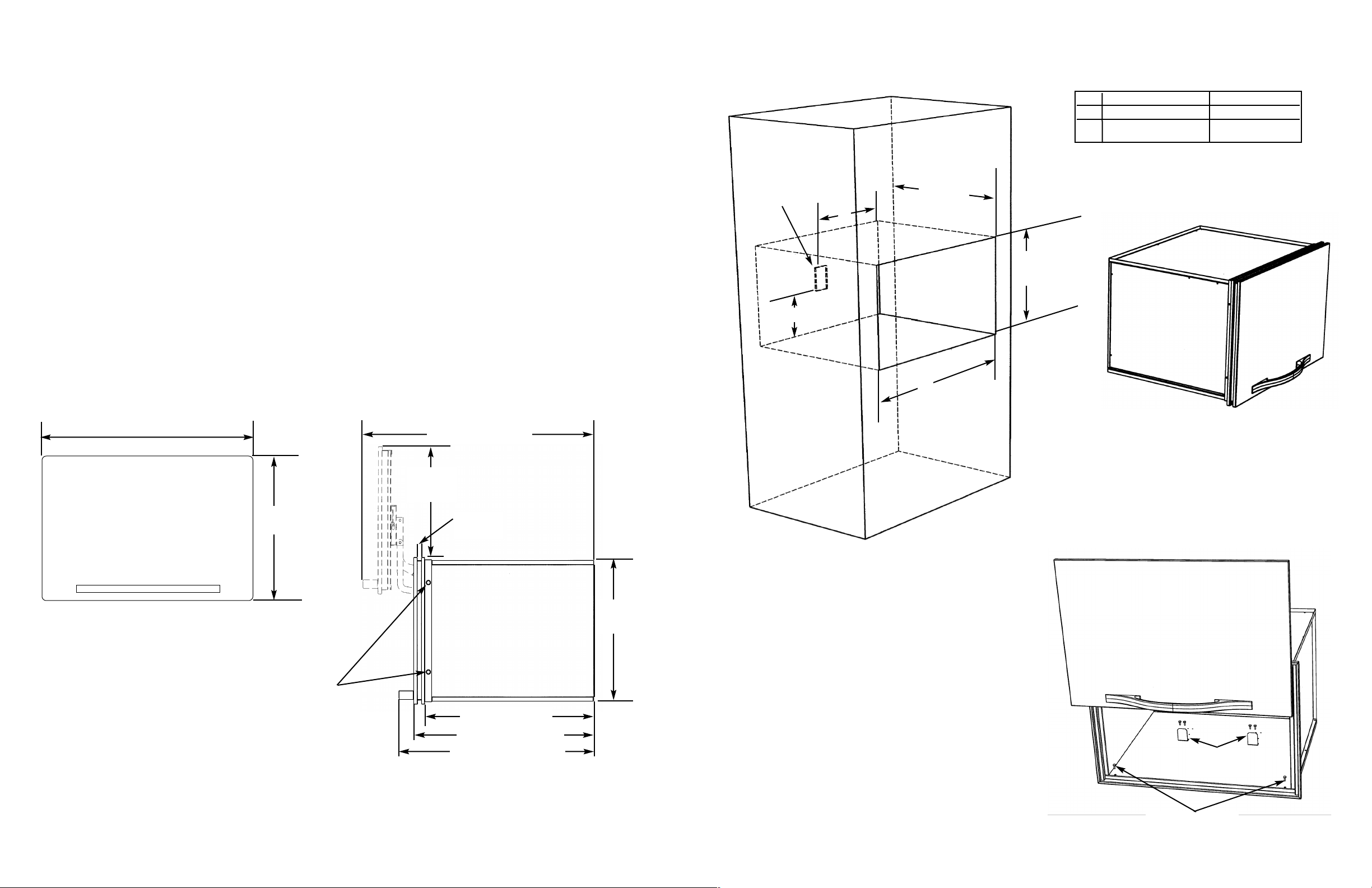
CABINET MOUNTING
Place the multi-use chamber in the cabinet cut-out.
Use the two enclosed screws to attach unit to the cabinet.
The adjustment brackets are used to adjust how far the
microwave slides back into the chamber.
BASIC DIMENSIONS
Mounting screws
Adjustment
brackets
DMWC170-26 1/2” (67.3 cm)
DMWC100-29 1/2” (74.9 cm)
19 1/4”
(48.9 cm)
31 1/4” (79.4 cm)
22 7/8” (58.1 cm)
24 3/8” (61.9 cm)
26 3/8” (67.0 cm)
14 3/4”
(37.5 cm)
18 1/2”
(47.0 cm)
*Adjust trim to door by loosening screws on
all four sides of trim to achieve proper
spacing (9/16” [1.4 cm]) if necessary.
Retighten screws after making adjustment.
*
*
9/16”
(48.9 cm)
IMPORTANT: PLEASE READ AND FOLLOW
•Before beginning, please read these instructions completely and carefully.
•The installer should leave these instructions with the consumer for future reference.
•Viking multi-use chambers are not compatible with Viking Convection Microwaves
GENERAL INFORMATION
1. All openings in the wall behind the appliance and under the appliance shall be sealed.
2. Do not obstruct flow of ventilation air.
3. The misuse of doors can result in possible hazards and/or injuries.
UNPACK
1. Locate the unit near installation area.
2. Remove all banding from around carton. Lift carton up and off of the multi-use chamber.
3. Remove all tape and packaging material from the outside and inside of the chamber.
4. Keep all carton packaging until your multi-use chamber has been thoroughly inspected and found to be in good
condition.
CABINET CUTOUT
2
DMWC170 DMWC100
A 25” (63.5 cm) 28” (71.7 cm)
B 12 1/2” (31.75 cm) 14” (35.55 cm)
24”
(61.0 cm)
B
10” (25.4 cm)
Recommended
Electrical
Outlet
Location
A
18 5/8”
(47.3 cm)
3
Loading ...
Loading ...