Loading ...
Loading ...
Loading ...
NOTE:This unitis shippedwithoutgasolineor oil inthe engine.Be
certainto serviceenginewithgasolineandoil as instructedin the
Operationsectionof this manualbeforeoperatingyourmachine.
NOTE:Referenceto rightand lefthandsideof the tiller is observed
fromthe operatingposition.
OPENING CARTON
1. Removethe staples,breakthe glue on the top flaps,orcut the
tapeat the end of the cartonand peel it alongthe top flapto open.
2. Removeall looseparts.
3. Cut the cornersandlaythe cartondown fiat.
4. Removeloosepackingmaterial.
REMOVING UNIT FROM CARTON
1. Use the handlebarto liftand pullthe tiller backwardsto a flat
area.Checkthecarton thoroughlyfor looseparts.
2. Extendthe controlcableand lay it on thefloor.Becarefulnot to
bendor kinkthe controlcable.
LOOSE PARTS IN CARTON
• HandlebarAssembly
• Tiller
• EngineOil
• Operator'sManual
• Shift Rod
• DepthStake
ATTACHING THE DEPTH STAKE
Beforeassembly,disconnectthe sparkplugwireand groundit
againstthe engineto preventunintendedstarting.
1. Tipthe tiller forwardso that it restson thefrontcounterweight.
2. Unthreadthe "T" knobfromthe topof the depthstakeand remove
theflat washerand hexbolt. Removethecotter pinfromtheclevis
pin. See Figure1.
Cotter Pin
Fiat Washer
Hex
Bolt
Depth
Stake
Figure1
3. Raisethefine shieldhingeflapassemblyand insertthe depth
stakeassemblyin the slot, underthe fineshieldandup through
the tine shieldassembly.
4. Insertthe clevispinthroughthe fineshieldanddepthstake
assemblies.Secureit with the cotterpin.
5. Insertthe hex bolt intothe top holeof the depthstakeassembly.
Placethe flat washeron the hex boltandthreadthe T-knobonto
the hex bolt.Tightensecurely.SeeFigure1.
6. Tip the tiller backdownso thatit restson the tines.
ATTACHING THE HANDLE ASSEMBLY
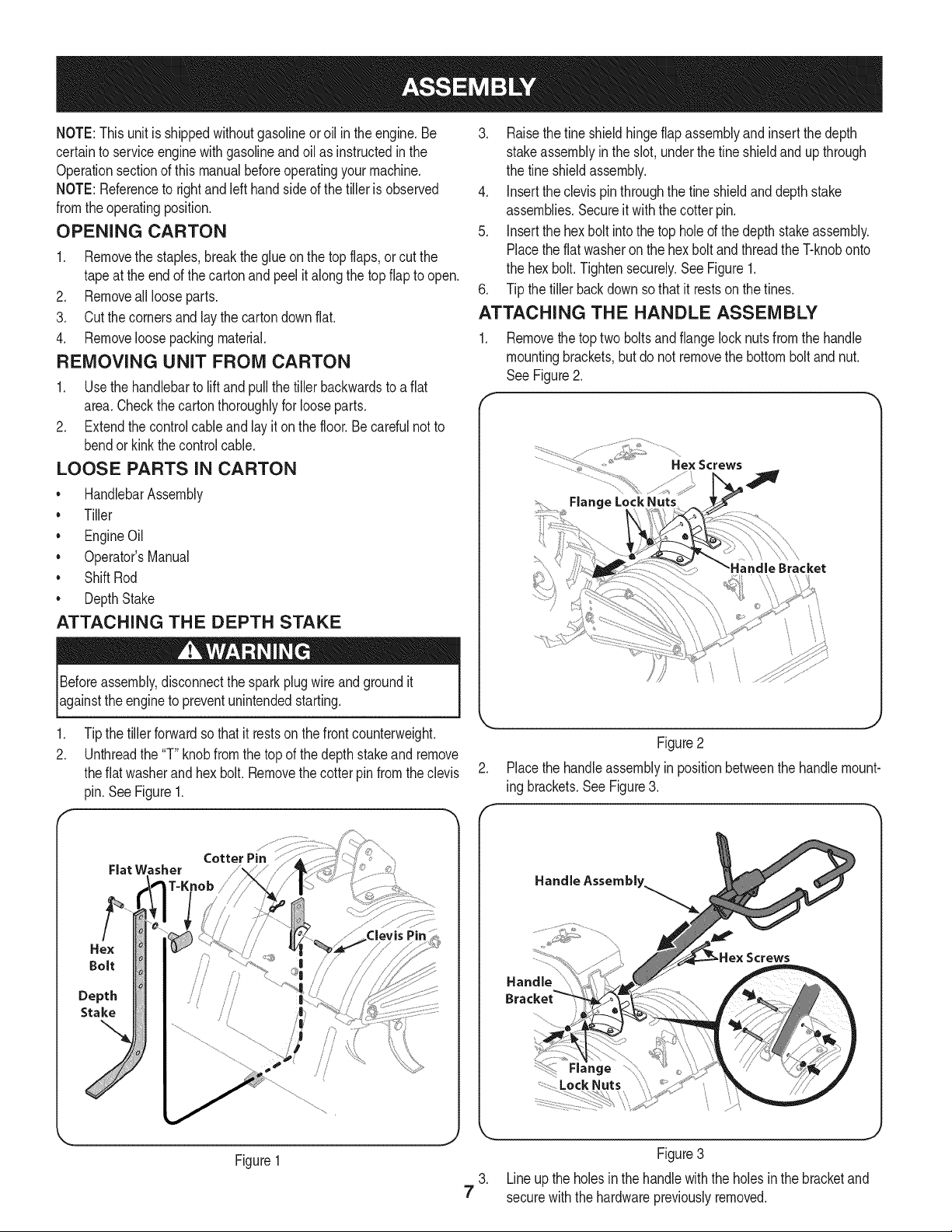
1. Removethe toptwo boltsand flangelock nutsfrom the handle
mountingbrackets,but do not removethe bottombolt andnut.
See Figure2.
f
.................. _,_i"_i_:...........
................... " Hex Screws
Flange LockNuts
Figure2
2. Placethe handleassemblyin positionbetweenthe handlemount-
ing brackets.See Figure3.
Handle Assembly.
Screws
7
J
Figure3
3. Lineup the holesinthe handlewiththe holesin the bracketand
securewiththe hardwarepreviouslyremoved.
Loading ...
Loading ...
Loading ...