“ROTANTE” pizza oven
R-002 100218
Page 1 of 43
Manufacturer:
Univex Corporation: 3 Old Rockingham Road, Salem NH 03079
Phone: 603-893-6191
Website: www.univexcorp.com
USER MANUAL AND MAINTENANCE
GUIDE
This user manual is part of the machine and should be kept in proper condition in
order to maintain its integrity and to allow for consultation during the equipment's
life cycle.
DOME47RT DOME 59RT
DOME47FT DOME 59FT
WARNING: Read the instructions before using the equipment.
REVIEW CAREFULLY THIS MANUAL BEFORE
CARRYING OUT ANY OPERATION ON THE EQUIPMENT
“ROTANTE” pizza oven
R-002 100218
Page 2 of 43
The manufacturer has the right to make changes to the production model and manual
without the obligation to update previous production models and manuals.
Please read this entire manual before installing the oven. Failure to follow
instructions may result in property damage, bodily injury or even death.
Contact your local building or fire officials about restrictions and installation
inspections in your area.
FOR YOUR SAFETY
Do not store or use gasoline or other flammable vapour or liquids in the
vicinity of this or any other appliance.
Also, always keep the area under and around this appliance free and clear of any and all
combustible materials. Do not obstruct the flow of combustion and ventilation air.
DO NOT THROW THIS MANUAL AWAY
RETAIN THIS MANUAL FOR FUTURE REFERENCE.
ADDITIONAL COPIES AVAILABLE UPON REQUEST.
IMPORTANT: Consult your local gas supplier for a statement outlining a
procedure to be followed in the event you smell gas. Post the statement in a
prominent location.
WARNING: Improper installation, adjustment alteration, service or
maintenance can result in property damage, injury or death. Read
the installation, operation and maintenance instructions thoroughly
before installing or servicing this equipment
It is recommended that this oven be installed, maintained and serviced by
authorised professionals.
Additional copies of this manual and prompt responses to
service / maintenance questions are available from Univex.

“ROTANTE” pizza oven
R-002 100218
Page 3 of 43
Table of Contents
1. GENERAL NOTICE ....................................................................................................... 4
1.1 Test and warranty ................................................................................................... 4
1.2 Client's responsibilities ............................................................................................ 4
1.3 Equipment safety .................................................................................................... 5
2. GENERAL INFORMATION ............................................................................................ 6
2.1 Definitions and icons ............................................................................................... 6
2.1.1 Definitions ............................................................................................................ 6
2.1.2 Icons .................................................................................................................... 7
3. MANUFACTURER'S NAME AND ADDRESS ................................................................ 9
3.1 Information on technical support and maintenance .............................................. 10
4. TECHNICAL INFORMATION AND SPECIFICATIONS ............................................... 11
5. GENERAL DESCRIPTION .......................................................................................... 13
6. INSTALLATION AND STORAGE ................................................................................ 14
6.1 Inspections upon receipt of the equipment ........................................................... 14
6.2 Storage ................................................................................................................. 14
7. ASSEMBLING INSTRUCTIONS .................................................................................. 15
7.1 Clearances ........................................................................................................... 15
7.2 Positioning of the oven ......................................................................................... 16
7.3 Electrical connection ............................................................................................. 18
7.4 Hydraulic connection ............................................................................................ 19
7.4.1 Gas conversions ................................................................................................... 21
8. USING THE OVEN ...................................................................................................... 25
8.1 Equipment's functions and controls ...................................................................... 25
8.2 First startup of the oven ........................................................................................ 27
8.3 Normal operation .................................................................................................. 29
8.3.1 Manual operating mode. .................................................................................... 30
8.3.2 Automatic operating mode. ................................................................................ 31
8.3.3 Sheated element control and setup ................................................................... 31
8.3.4 “BAKING 1” and “BAKING 2” programs. ............................................................ 33
8.4 Program complete. ............................................................................................... 34
9. Setting parameters for the oven's general configuration. ............................................. 35
10. MAINTENANCE ....................................................................................................... 37
10.1 Daily maintenance ................................................................................................ 37
10.2 Periodic maintenance ........................................................................................... 37
11. INCONVENIENCES AND ANOMALIES .................................................................. 39
12. INTERVENTION REQUEST FORM - REPLACEMENT PARTS .............................. 41
13. REPLACEMENT PART LIST ................................................................................... 42
14. ATTACHMENT LIST ................................................................................................ 42
15. WARRANTY ............................................................................................................ 43

“ROTANTE” pizza oven
R-002 100218
Page 4 of 43
1. GENERAL NOTICE
1.1 Test and warranty
The oven and its components have already been tested at our plant in compliance with the
applicable regulations and laws, and are delivered ready for use.
Any attempt to disassemble, change or, in general, tamper with any part of the equipment
will invalidate the
warranty.
Any improper use of the oven, as well as any attempt to disassemble and modify the oven,
can lead to accidents and therefore Univex declines any responsibility for potential injuries
or damages resulting from tampering. In case of anomalies, please consult your
local authorized customer service center and, more specifically, contact directly the
manufacturer for help with assembling, installing or moving the equipment. The
manufacturer shall be relieved from any responsibility in the following cases:
Improper use of the equipment by inadequately trained personnel.
Installations that are not compliant with applicable laws in the country of use and
performed by non-authorized personnel.
Scheduled routine maintenance that was not carried out or that was performed
incorrectly.
Use of non-original or non-approved replacement parts.
Partial or total non-observance of the instructions.
The warranty is effective as per 12 months since the delivery date and covers the
replacement or repair of any faulty part, except for electric or electronic components and
parts. The manufacturer should be notified of any visible defect or anomaly within 5 days
since the date of receipt to be able to conduct an inspection.
Any other defect that might be seen upon receipt of the oven should be notified within 5
days since it was noticed and in any case within maximum 6 months.
The buyer has the right to request the repair or replacement of the faulty parts only, since
the warranty does not cover in any way the damages related to any other direct or indirect
cause.
The repair and replacement of faulty parts should be requested within the maximum limit
as outlined in the warranty unless otherwise specified by law.
Damaged or faulty parts will be repaired or replaced by the manufacturer. The buyer is
therefore responsible for sending free of carriage charges the above-mentioned parts to
the manufacturer, who will resend them to the buyer.
1.2 Client's responsibilities
The client should be held responsible for the following:

“ROTANTE” pizza oven
R-002 100218
Page 5 of 43
Reading thoroughly this user manual before installing and using the equipment
Installing and positioning correctly the oven as per instructions outlined in chapter 6
of this manual
Observing the applicable regulations and laws for gas interconnection or use of
solid fuels
Connecting and implementing the fume extraction system / Connecting the flue pipe
Cleaning and care of the oven
Routine maintenance
1.3 Equipment safety
Please read carefully this booklet and its safety guidelines on use and
maintenance. This manual's aim is to share key rules and criteria with the operators
in order to guarantee their safety and extend the oven's operating time. This manual
shall be read and understood by all members of the personnel who have been
authorized to operate on the oven before its first startup.
This instructions booklet must be stored together with the equipment for future
reference. In case you want to sell or transfer the equipment, make sure to include
this booklet so that the new user can be informed about the operating instructions
and related warnings. It must be stored in a safe and dry place, and should be easily
accessible for consultation. In case it falls apart or gets lost, you can request a copy
directly to the manufacturer; in case of doubt, please consult your local customer
support center or contact directly Univex.
This equipment is designed for baking pizzas. It should not be used for any other
purpose; any other use is to be considered inappropriate.
Maintenance, adaptation to another type of gas, startup and functional checks
should be carried out only by qualified personnel.
We recommend you to subscribe a servicing agreement with your supplier.
Please contact an authorized technical support center to repair and request original
spare parts.
The equipment is designed for commercial use and should be used by trained
personnel.
This type of equipment is designed for use in commercial applications, such as
restaurants, cafeterias, hospitals and commercial businesses, like bakeries,
butcheries, etc., but it is not designed for the continuous production of food.
The manufacturer declines any responsibility for potential damages due to non-
observance of the instructions for use and maintenance, or due to inappropriate use
of the equipment.
“ROTANTE” pizza oven
R-002 100218
Page 6 of 43
2. GENERAL INFORMATION
This user manual is part of the standard-production equipment and represents a
fundamental support for its startup and appropriate use.
Read it carefully and thoroughly before installing and using the equipment.
In case of reselling, the manual shall be included as part of the equipment.
Partial reproduction of this document without the written authorization by Univex is
forbidden.
2.1 Definitions and icons
Here below we illustrate a series of definitions, specific terminology and icons that have
been used in this manual.
2.1.1 Definitions
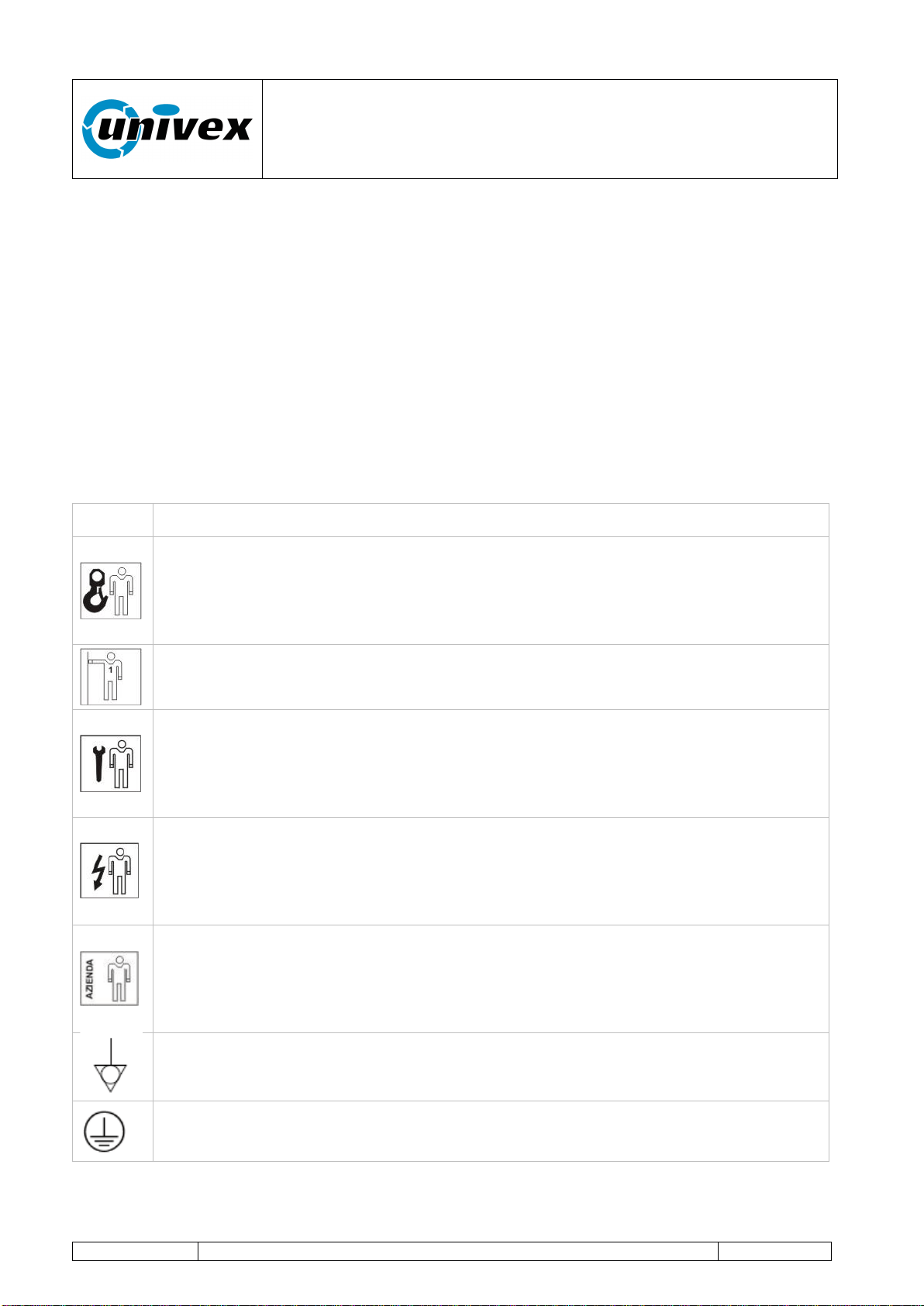
Icon
Description
Lifting and Handling Equipment Operator: the operator who has been trained
to use equipments for lifting and handling materials and machines. Handling
operations should be carried out according to the instructions described in this
manual and in compliance with the applicable laws in the country where the
equipment is used.
First Level Operator: the operator, with no specific skills, who is able to use
the equipment in normal working condition and for simple maintenance
interventions.
Mechanical Maintenance Technician: the qualified technician who has been
trained to operate the equipment in normal working condition and to operate on
mechanical - hydraulic - pneumatic gears in order to make adjustments,
maintenance interventions, installations or repairs according to the instructions
outlined in this manual.
Electrical Maintenance Technician: the qualified technician who has been
trained to carry out interventions on live electrical racks, branching boxes and
electrical fittings, as well as to operate the equipment under normal working
conditions and to make interventions on electrical systems for adjusting,
maintenance, installation and repair operations.
Manufacturer's Technician: the qualified technician who has been designated
by the manufacturer to carry out complex operations in specific situations or, in
any case, on the basis of what has been agreed upon with the user. Depending
on each case, the personnel is requested to have mechanical and/or electrical
and/or electronic and/or IT skills.
Equipotential bonding
Ground protection
“ROTANTE” pizza oven
R-002 100218
Page 7 of 43
2.1.2 Icons
NOTE
Shows guidelines or key information described in the user manual, that
should be read carefully, for the most appropriate use of the equipment.
DANGER
Warns against the risk of injuries, included lethal accidents, or serious
health damages.
CAUTION
Indicates a situation that could, even indirectly, be harmful for persons,
things and the environment with consequences of economic losses.
WARNING
Indicates that you should pay special attention to the instructions. Non-
observance of such warnings could lead to malfunctions or dangerous
conditions or damages.
“ROTANTE” pizza oven
R-002 100218
Page 8 of 43
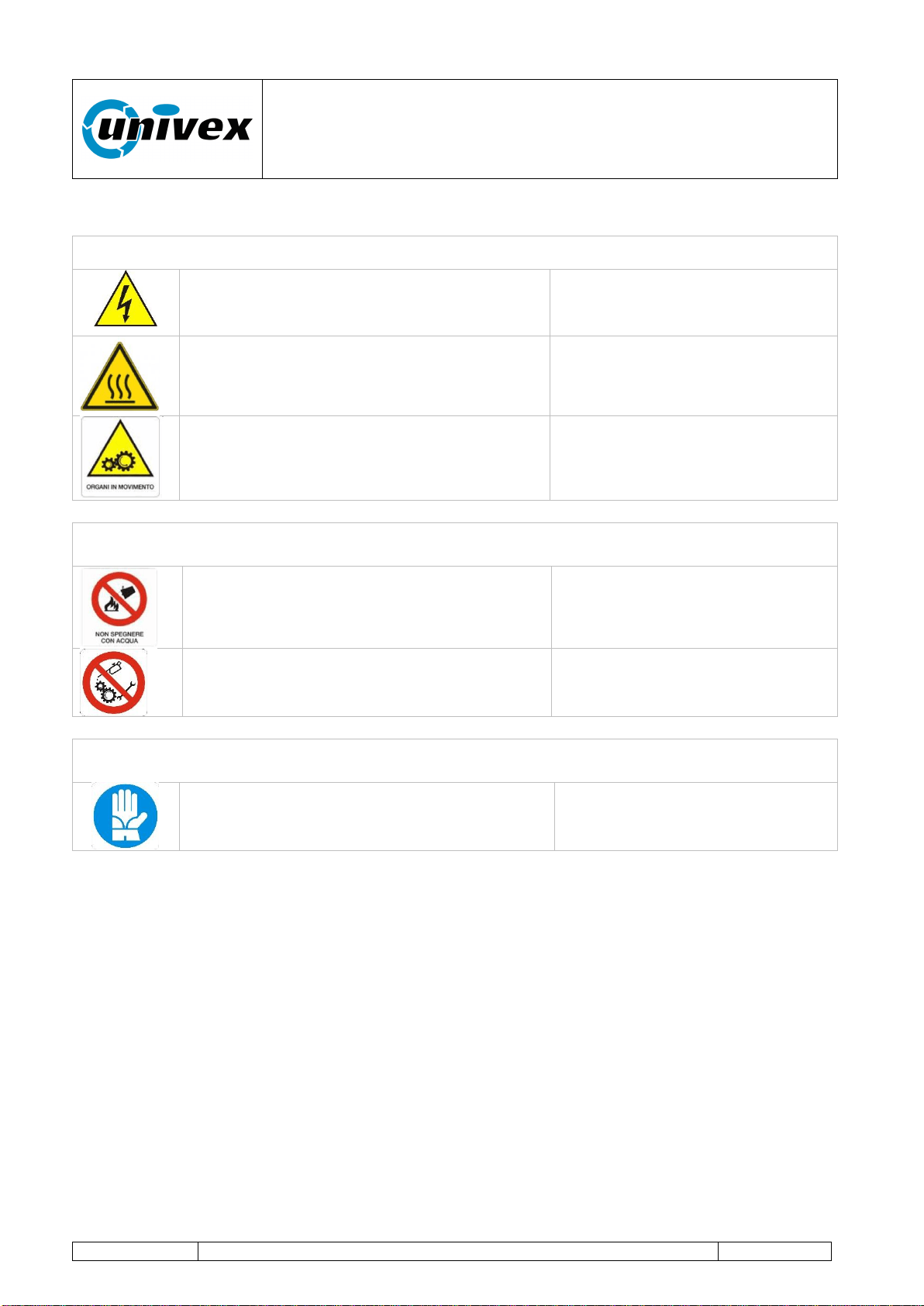
HAZARD PICTOGRAMS
Warning signs (Warning, Caution, Check)
High voltage danger
Hot surface
Moving gears danger
Prohibition signs (Dangerous behaviors, Danger, Make-and-Break, Emergency
device)
Prohibition to use water to extinguish fires
Prohibition to clean, oil, grease, repair or
adjust moving gears by hand
Mandatory signs (specific action or behavior, obligation to wear a personal safety
device)
Mandatory protective gloves
“ROTANTE” pizza oven
R-002 100218
Page 9 of 43
3. MANUFACTURER'S NAME AND ADDRESS
This product has been manufactured by:
Forni Ceky Srl
Via industriale 21/23
25030 Lograto (BS) ITALY
Tel 030.9972249 FAX 030.9972818
[email protected] www.ceky.it
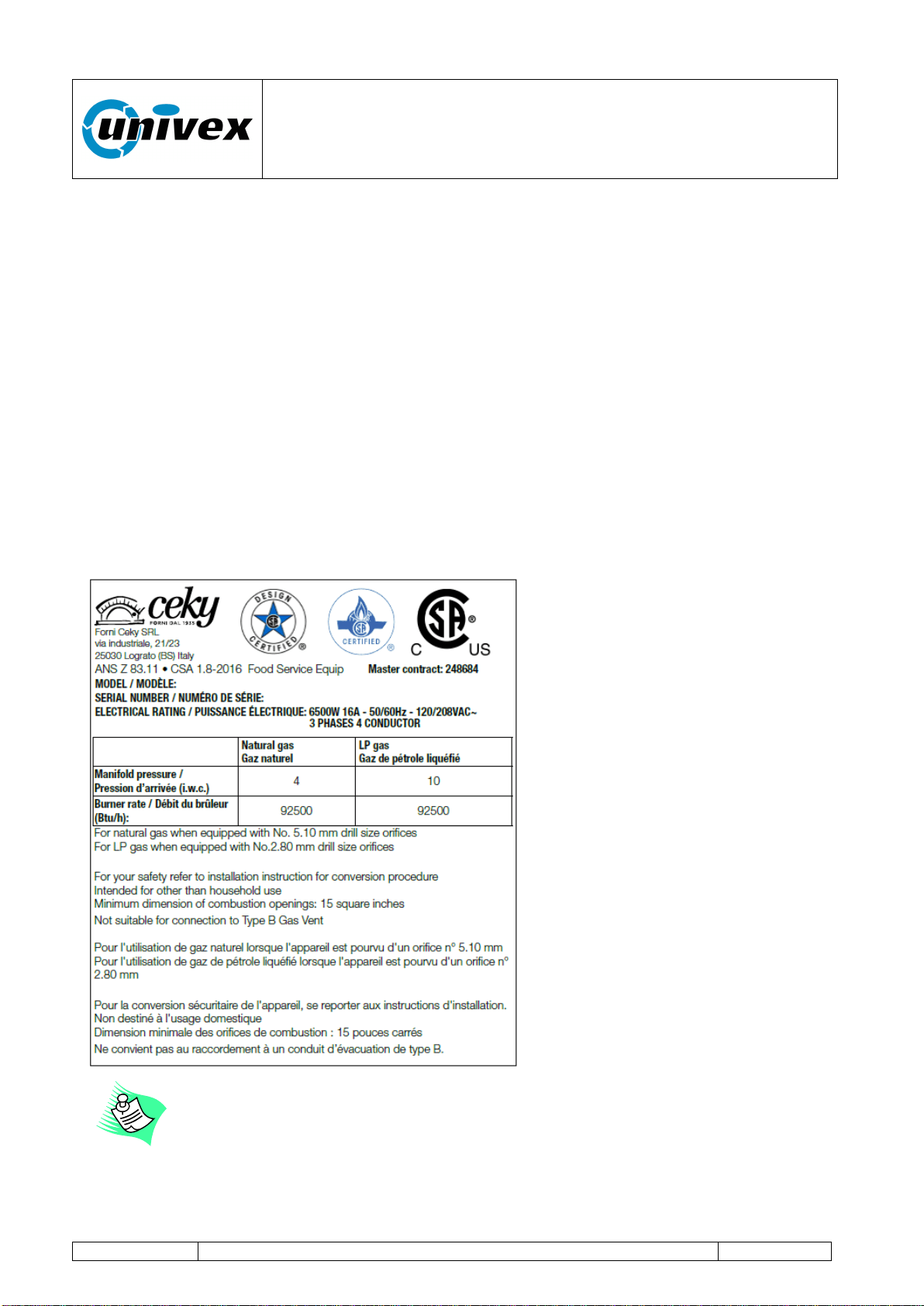
The plate on the oven front face includes all the identification data related to the oven itself.
Figure 3.1 shows a sample plate that is applied to the frontal face of the oven, near the
connection box: the information shown is exclusively indicative.
Fig.3.1 Sample plate
It is absolutely forbidden to remove or tamper with the plate; in case of
accidental damage, please contact the manufacturer to request a copy.
“ROTANTE” pizza oven
R-002 100218
Page 10 of 43
3.1 Information on technical support and maintenance
In case of failures or malfunctions, please contact our Customer Support Center:
Univex Corporation
603-893-6191
For communications or requests of information or replacement parts, please send the
"REPLACEMENT PART ORDERING, FAULT REPORTING, INFORMATION" form in the
Attachment 1 to our customer support center.
To be covered for the entire duration of the warranty period, the buyer
should follow strictly the instructions outlined in this manual. In case of non-
observance, Univex is relieved from any responsibility for
inconveniences or anomalies or damages to the equipment or to
third parties.
In order to adapt the equipment to technological advances and to specific
needs at production level, the manufacturer can decide, without prior
notice, to make any change on the equipment without the obligation to
update previous production models and manuals.
Furthermore, although the illustrations shown in this manual are slightly
different from the equipment you own, its safety and operating instructions
are always guaranteed.
“ROTANTE” pizza oven
R-002 100218
Page 11 of 43
4. TECHNICAL INFORMATION AND SPECIFICATIONS
Table 4.1.
DOME47RT/ DOME47FT
Natural gas
Total Input Rate (Btu/hr)
92500
N. of burners and input rate (Btu/hr)
1 x 92500
Manifold pressure (iwc)
4
Nozzle orefices 1/100mm
510
Air adjustment mm
8
LP Gas
Total Input Rate (Btu/hr)
92500
N. of burners and input rate (Btu/hr)
1 x 92500
Manifold pressure (iwc)
10
Nozzle orefices 1/100mm
280
Air adjustment mm
Open
DOME59RT/DOME59FT
Natural gas
Total Input Rate (Btu/hr)
97500
N. of burners and input rate (Btu/hr)
1 x 97500
Manifold pressure (iwc)
4
Nozzle orefices 1/100mm
540
Air adjustment mm
8
LP Gas
Total Input Rate (Btu/hr)
97500
N. of burners and input rate (Btu/hr)
1 x 97500
Manifold pressure (iwc)
10
Nozzle orefices 1/100mm
290
Air adjustment mm
Open
Models
Production
(hourly)
1
Burner
power
Btu
Rated
power
in KW
Internal chamber
Diameter
cm/inches
Deck
diameter
cm/inches
Weight
Kg/Lb
DOME47RT
DOME47FT
100
92500
6,5
120cm
47,24”
100cm
39,37”
2000Kg
4409Lb
DOME59RT
DOME59FT
180
97500
6,5
150cm
59”
140cm
55,11”
2500Kg
5511Lb
1
Data refer to pizzas with a diameter of 30 cm avg. cooking time of 2.30 minutes

“ROTANTE” pizza oven
R-002 100218
Page 12 of 43
Drawing
Details
DOME47RT
DOME 59RT
Height H
185cm
72,83”
Length L
165cm
65”
Height H
185cm
72,83”
Length L
195cm
76,77”
External diameter
165cm
65”
External diameter
195cm
76,8”
DOME47FT
DOME59FT
Height H
185cm
72,83”
Length L
205cm
80,7”
Height H
185cm
72,83”
Length L
235cm
92,5”
Depth D
165cm
65”
Depth D
195cm
76,77”
H
L
L
H
D
“ROTANTE” pizza oven
R-002 100218
Page 13 of 43
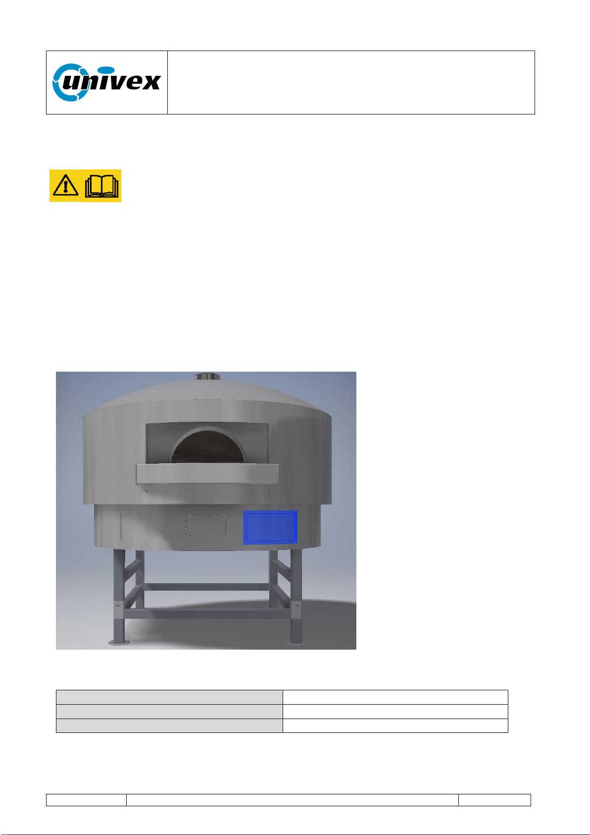
5. GENERAL DESCRIPTION
The Rotating model is characterized by an innovative baking technology which is based on
an independent dual heating system (chamber gas burner and electric bedplate) and a
variable speed rotating bedplate or deck.
The highly efficient baking chamber, which is made of high-quality refractory materials,
combined with a smart control of the burner flame and the rotating deck, helps the oven
deliver excellent performance with high levels of hourly production.
The oven should be used exclusively for baking pizzas and solid foodstuff
for human consumption. It should not be used with liquid or gas products,
containers or packages that have been hermetically sealed.
This type of equipment is designed for use in commercial applications, such
as restaurants, cafeterias, hospitals and commercial businesses, like
bakeries, butcheries, etc., but it is not designed for the continuous
production of food.
As regards airborne noise emissions, the weighted sound pressure level A
is lower than 70 dB(A)
“ROTANTE” pizza oven
R-002 100218
Page 14 of 43
6. INSTALLATION AND STORAGE
6.1 Inspections upon receipt of the equipment
Lifting and Handling Equipment Driver: the operator who has been trained to
use equipments for lifting and handling materials and machines (paying special
attention to the instructions provided by the manufacturer), in compliance with
the applicable laws in the country where the machine is used.
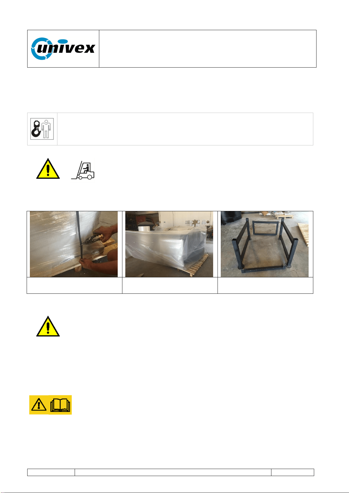
For handling, loading and unloading operations, please use a pallet
carrier (e.g. a forklift truck) with a minimum loading capacity of
4,000 kg and with long forks. Arrange the pallet on a surface where
there's enough space for unpacking operations.
Remove the packing and make sure the content is intact.
Oven's metal standing
support
In case of damage or missing elements or in case you see defects or
damages, please do not try to repair the equipment, but instead contact our
customer support center indicating the equipment's model, code and serial
number (see Fig. 3.1 Sample plate).
6.2 Storage
In case the equipment is not used for a long period of time, please protect
the equipment from dust and humidity. Remove the air bubble packing to
allow for an adequate ventilation and to prevent the formation of condensed
steam inside the oven.
“ROTANTE” pizza oven
R-002 100218
Page 15 of 43
7. ASSEMBLING INSTRUCTIONS
7.1 Clearances
WARNING: If this oven is not properly installed a fire may result.
To reduce the risk of fire, follow this installation instructions. A major cause of oven related
fire is failure to maintain required clearances (air spaces) to combustible materials. It is of
utmost importance that this oven be installed only in accordance with these instructions.
Please read this entire manual before you install the oven. Failure to follow instructions
may result in property damage bodily injury or even death. Contact your local building or
fire officials about restrictions and installation inspection in your area.
CLEARANCES
I) The Univex oven must have a minimum 1" clearance to combustibles from all
size and 16" from combustibles from the top.
If building a facade that will contact the oven, use completely non-combustible
materials (when non-combustible building materials contact the body of the oven,
the clearances to combustibles are transferred to those non combustibles). Please
note that standard dry-wall (or sheet rock) is considered a combustible.
II) Any facade above and/or 6 inches to either side of the oven doorway, must be
constructed of non combustible building materials
III) Install this oven only on non combustible floors. The non combustible floor surface
should extend 40 inches out in front of the oven and extend 32 inches to either side
of the oven doorway.
IV) Leave a clearance of at least 200cm
2
under the oven
V) Leave a clearance for servicing and proper operation in case you are covering the
iron stand
WARNING: installation and servicing of this product could expose you to
glass wool/ceramic fibres and dust.
ALWAYS WEAR RESPIRATORY AND EYE PROTECTION WHEN INSTALLING OR
SERVICING THIS APPLIANCE
“ROTANTE” pizza oven
R-002 100218
Page 16 of 43
7.2 Positioning of the oven
The equipment should be installed in a well-ventilated place, and possibly
located under a smoke extraction panel in order to ensure the complete
evacuation of exhaust gases, or directly connected to the flue pipe according
to the construction type. The flue outlets for combustion smoke should be
sized and engineered according to the applicable provisions.
Make sure that the air inflow needed for combustion is guaranteed by a minimum surface
of 5,4 ft
2
(oven's lower area) and with an adequate air recirculation in the upper area
through a minimum aeration zone of one squared meter.
The oven should be positioned in such a way that it can be accessed during
maintenance interventions. Once it has been positioned, please check the
vent outlets. The combustion air amount for a correct combustion is 1907 ft
3
/h
for 47 serie, while it's 2013 ft
3
/h for 59 serie. Minimum distances to be kept
between the equipment and adjacent walls should not be less than 1 inch on
each side.
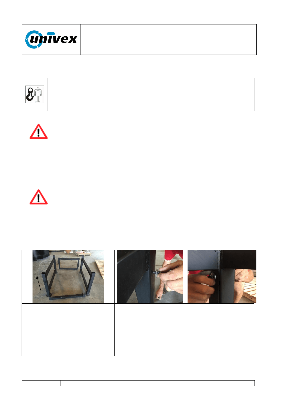
The figures below show the assembling operations to mount the oven's standing support
and then to position the oven.
The oven's standing support is
made of 4 metal tubular elements
that are respectively made of two
sides with four verticals, a rear
part and a front part.
Arrange the standing support in
the desired area and assemble
the various parts as illustrated.
Position the rear support on the sides, align the 4
holes and connect the parts with nut and bolt
including the washers on both sides. Repeat the
operation for the front support (n. 2 holes)
Lifting and Handling Equipment Operator: the operator who has been trained
to use equipments for lifting and handling materials and machines. Handling
operations should be carried out according to the instructions described in this
manual and in compliance with the applicable laws in the country where the
equipment is used.
Rear
support
Vertical
“ROTANTE” pizza oven
R-002 100218
Page 17 of 43
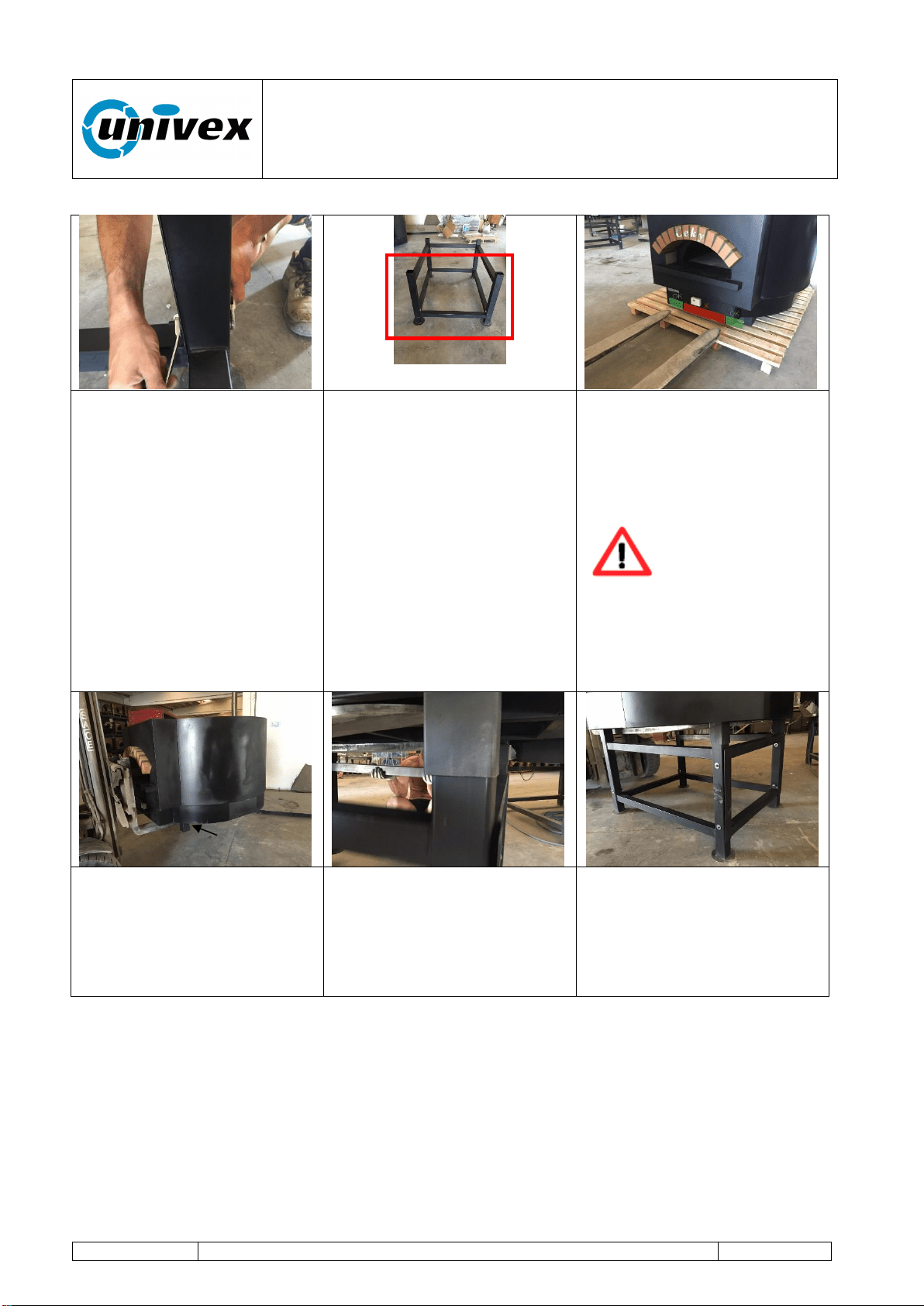
Tighten firmly all the parts of
the standing support.
Once the standing support
has been mounted, position
the structure in the area
where the oven will be
installed.
The red panel shows the
side where the oven's door
will be positioned.
Load the oven's body
inserting the forks as shown
in the figure (see green
rectangles, close to the
oven's standing feet).
The incorrect
positioning of the
forks can severely
damage the
equipment.
DO NOT insert the forks in
the area marked as red in
the figure above.
After reaching the
installation position, lift the
oven up to a working height
for the correct positioning on
the standing support.
Align the standing support's
verticals under the oven's
standing feet with simple
manual operations.
Lower the oven till it lays
completely on the standing
support's verticals.
Standing feet
“ROTANTE” pizza oven
R-002 100218
Page 18 of 43
7.3 Electrical connection
The correct functioning and the observance of safety requirements are
guaranteed only if the equipment is connected to an efficient electrical
system that is installed according to the applicable laws. Univex does not
take any responsibility for any damage to the equipment or to third
parties that is caused by the use of an electrical system that is not
compliant with the applicable laws.
electrical and grounding connections must comply with the applicable
portions of the national electrical code and/or other local electrical codes.
disconnect electrical power supply and place a tag at the disconnect switch
to indicate you are working on the circuit.
appliances equipped with a connection box suitable for connection to a ½”
conduit.
Electrical Maintenance Technician: the qualified technician who has been
trained to carry out interventions on live electrical racks, branching boxes and
electrical fittings, as well as to operate the equipment under normal working
conditions and to make interventions on electrical systems for adjusting,
maintenance, installation and repair operations.
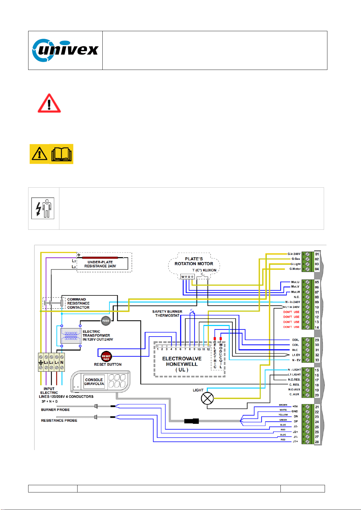
Fig.7.1 Wiring scheme – Printed copy inside connection box
“ROTANTE” pizza oven
R-002 100218
Page 19 of 43
It is the electrician's responsibility to size and install the oven's supply cable to the mains
system according to the oven's electrical specifications (see data on the plate).
All wiring should conform the Local codes and NEC.
The appliance must be electrically grounded in accordance with the local
codes, or in absence of local codes, with the National Electrical Code
NFPA 70, or the Canadian Electrical Code, CSA C22.2, as applicable.
The oven is equipped with a connection box, with terminal block inside,
located on front, right side, pre-drilled to receive a 1/2" conduit.
Install the conduit and proceed driving a proper branch circuit wire in the
conduit from the electrical panel to the connection box.
Loosen the upper screws of the field wire terminal.
Insert the bare wire ends in the field wire terminal openings according to
the scheme (fig 7.1) and tighten the screws securely.
NOTE: Electrical diagrams are located inside the connection box, shown below
Fig 7.1.1 Connection Box Highlighted view
7.3.1 Electrical specifications
Voltage
240/120 4W
Frequency
50-60Hz
Amp
16
“ROTANTE” pizza oven
R-002 100218
Page 20 of 43
7.4 Hydraulic connection
Mechanical Maintenance Technician: the qualified technician who has been
trained to operate the equipment in normal working condition and to operate on
mechanical - hydraulic - pneumatic gears in order to make adjustments,
maintenance interventions or repairs according to the instructions outlined in
this manual.
NOTE: INSTALLATION MUST CONFORM WITH LOCAL CODES, OR IN THE
ABSENCE OF LOCAL CODES, WITH THE NATIONAL FUEL GAS CODE, ANSI
Z223.1/NFPA 54, OR THE NATURAL GAS AND PROPANE INSTALLATION CODE,
CSA B149.1, AS APPLICABLE, INCLUDING:
1. The appliance and its individual shutoff valve must be disconnected from the gas
supply piping system during any pressure testing of that system at test pressures in
excess of 1/2 psi (3.5 kPa).
2. The appliance must be isolated from the gas supply piping system by closing its
individual manual shutoff valve during any pressure testing of the gas supply piping
system at test pressure equal to or less than 1/2 psi (3.5 kPa).
Connect the equipment to the gas distribution system with pipes and accessories to the
oven's input valve (standard coupling ½”).
Before turning on the burner:
- Check that the gas pressure entering the electrovalve is not higher than
the rated value.
- Verify that the connecting tubes are tightly sealed.
- Install a gas flow stop cock near the oven for possible emergency
operations and for a better regular management of the oven.
- Check the compatibility of the available fuel with the type of nozzles
mounted on the burner.
The type of nozzles, the fuel and the maximum operating pressure
are indicated in the plate on the oven. The flame minimum is factory
adjusted. Univex accepts no responsibility for any damage caused to
the equipment or to third parties as a result of an incorrect installation.
“ROTANTE” pizza oven
R-002 100218
Page 21 of 43
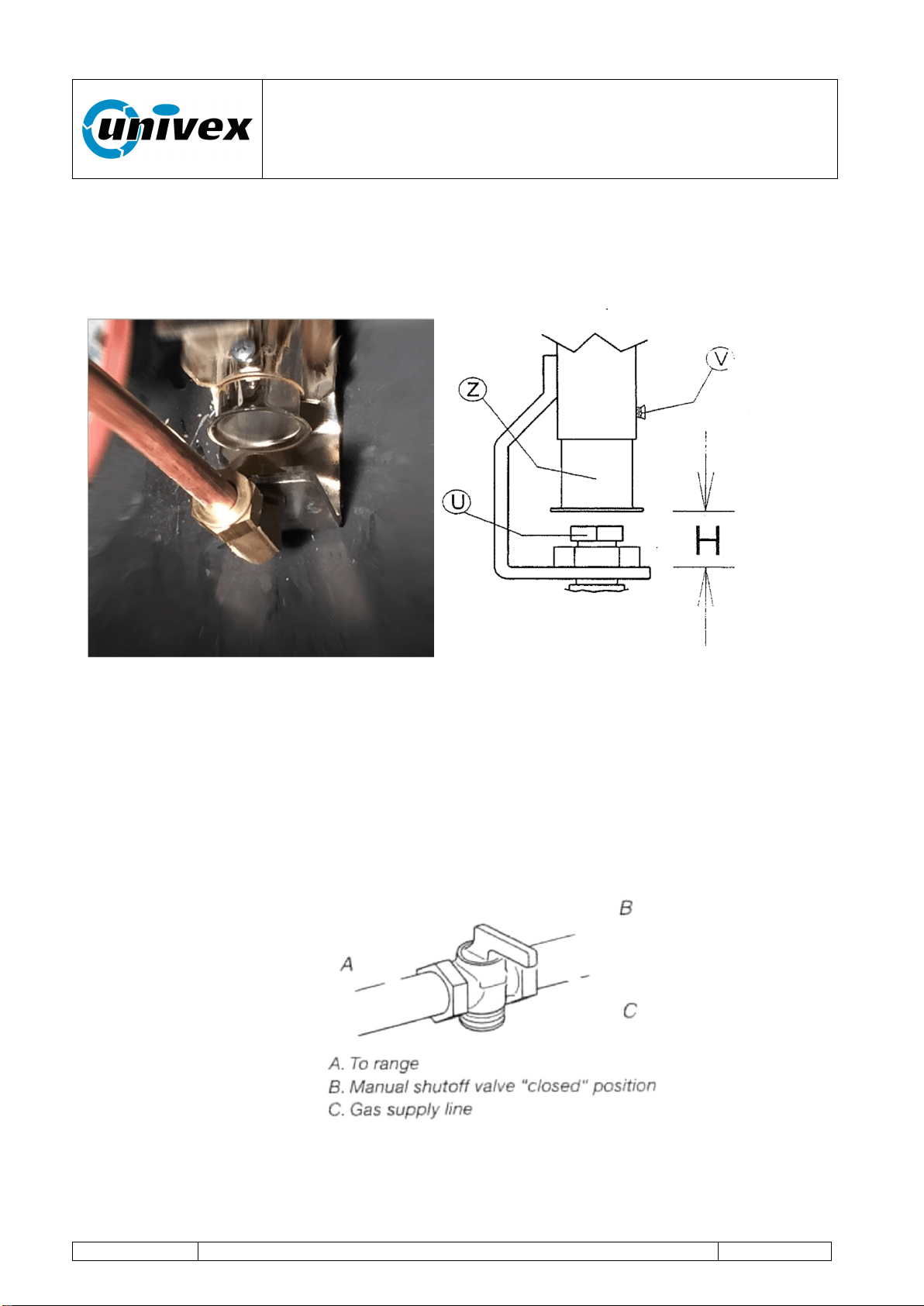
Fig 7.2 Nozzle-holder curve and damper sleeve
7.4.1 Gas conversions
Gas conversions from Natural Gas to LP gas or from LP gas to Natural gas must be done
by a qualified installer.
Converting Gas pressure regulator
1. Turn manual shutoff valve to the “closed” position.
2. Unplug range or disconnect power.
3. Remove the access cap by using a wrench, turning the access cap anticlockwise.
“ROTANTE” pizza oven
R-002 100218
Page 22 of 43
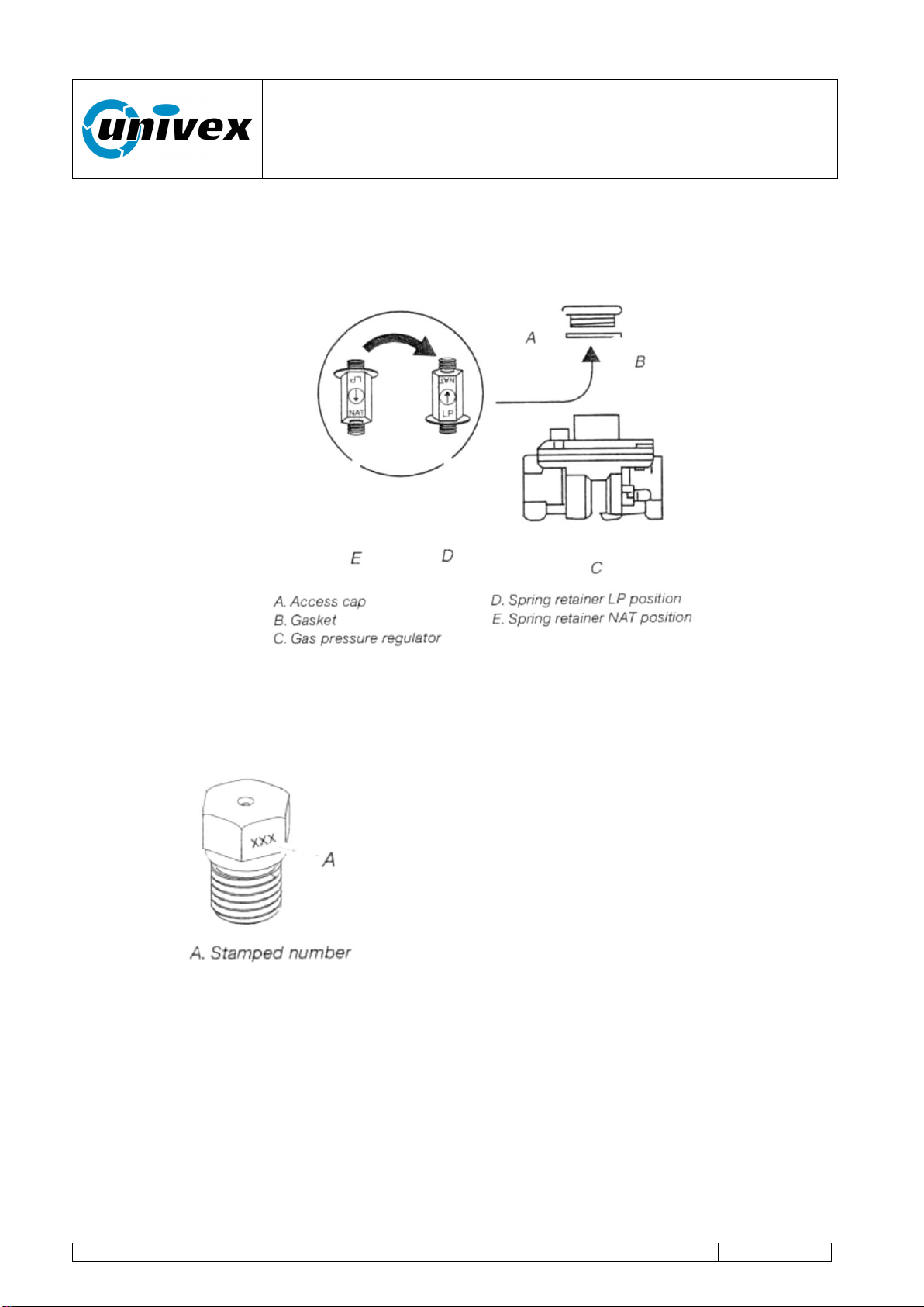
4. Remove sprint retainer from the cap by pushing against the flat side of the spring
retainer. Look at the spring retainer to locate the “NAT” or “LP” position.
5. Turn over the spring retainer so the “LP” is showing on the bottom.
6. Snap the spring retainer back into the cap.
7. Reinstall the cap onto the regulator.
8. With a nut driver remove the gas nozzle “U” by turning it anticlockwise and lifting out.
Set gas nozzle aside. Fig 7.2
9. Gas nozzles are stamped with a number on the side. The number represents the
size of the orifice in mm
10. Place the replaced nozzle in a plastic bag for future use and keep it with literature
package.
11. Loosen the V screw.
12. Shift the Z sleeve.
13. Adjust the Z sleeve to the distance H corresponding to the new installation (refer to
pag.11 for regulation values) and tighten the V screw.
14. Complete installation

“ROTANTE” pizza oven
R-002 100218
Page 23 of 43
Setting minimum / maximum gas levels
The maximum pressure setting must first be adjusted to ensure that burner will safely light
up, then the minimum pressure setting can be adjusted. Any adjustment of maximum
pressure setting influences minimum pressure setting, thus a minimum pressure setting
should always be re-adjusted after changing maximum value.
Maximum
Minimum
Natural gas
iwc (kPa)
3,55 (0,88)
0,4 (0,1)
LP gas
iwc (kPa)
9,7 (2,4)
1 (0,5)
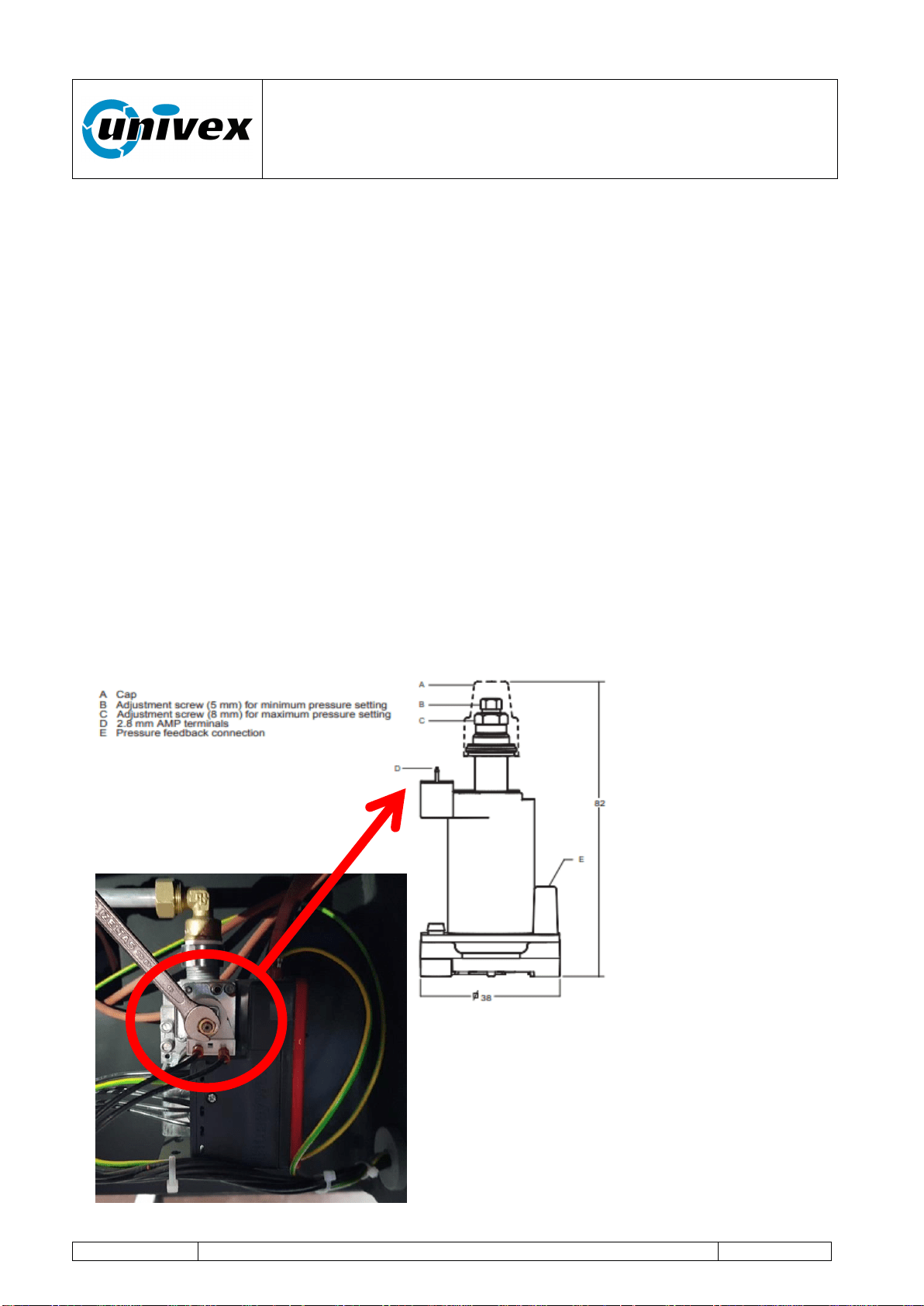
Adjusting the maximum pressure setting (see fig 7.3.)
Methode 1:
• Disconnect pressure feedback connection (if applicable).
• Connect a suitable pressure gauge to pipe line or to outlet pressure tap of gas control
concerned, to measure burner pressure (measuring point must be as near to burner as
possible).
• Disconnect electrical connection of Moduplus®.
• Energize operator, set control in operation and wait until an outlet pressure is recorded
on pressure gauge.
• Push shaft gently downwards by means of a suitable pin through the hole on the top of
the Moduplus® to the bottom and hold it on.
• If maximum rate pressure needs adjustment then use an 8 mm wrench to turn
adjustment screw for maximum pressure setting clockwise to increase or
counterclockwise to decrease pressure, until the desired maximum outlet pressure is
obtained. Release shaft.
• Check minimum pressure setting and readjust if necessary.(according instructions
below) • Mount cap and reconnect pressure feedback connection (if applicable).
• If minimum and maximum pressures are set, wire the Moduplus® in circuit.
• Close pressure tap screw
Methode 2:
• Disconnect pressure feedback connection (if applicable).
• Connect a suitable pressure gauge to pipe line or to outlet pressure tap of gas control
concerned, to measure burner pressure (measuring point must be as near to burner as
possible).
• Make sure that the appliance is in operation and the Moduplus® coil is energized with
maximum current.
• If maximum rate pressure needs adjustment then use an 8 mm wrench to turn
adjustment screw for maximum pressure setting clockwise to increase or counterclockwise
to decrease pressure, until the desired maximum outlet pressure is obtained. • Disconnect
electrical connection of Moduplus®
• Check minimum pressure setting and readjust if necessary. (according instructions below)
• Mount cap and reconnect pressure feedback connection (if applicable).
“ROTANTE” pizza oven
R-002 100218
Page 24 of 43
• If minimum and maximum pressures are set, wire the Moduplus® in circuit. • Close
pressure tap screw
Adjusting minimum pressure setting (see fig. 7.3.)
• Disconnect pressure feedback connection (if applicable).
• Connect a suitable pressure gauge to pipe line or to outlet pressure tap of gas control
concerned, to measure burner pressure (measuring point must be as near to burner as
possible).
• Disconnect electrical connection of Moduplus®.
• Energize operator, set control in operation and wait until an outlet pressure is recorded
on pressure gauge.
• If minimum rate pressure needs adjustment then use a 5 mm wrench to turn adjustment
screw for minimum pressure setting clockwise to increase or counterclockwise to decrease
pressure, until the desired minimum outlet pressure is obtained.
• Check if main burner lights easily and reliable at minimum pressure.
• Mount cap and reconnect pressure feedback connection (if applicable).
• Close pressure tap screw
Maintenance
It is recommended to check yearly the minimum and the maximum setting and readjust
them if necessary.
Fig 7.3
Fig 7.4
Frontal view of
the valve
“ROTANTE” pizza oven
R-002 100218
Page 25 of 43
8. USING THE OVEN
Once the installation has been successfully completed, the oven is ready to be operated.
CAUTION
When using the oven, please pay attention to the hot steam coming from
the oven's front opening (the oven's door).
8.1 Equipment's functions and controls
For ease of reference, hereinafter we will use some abbreviations/definitions whose
functions are described here below.
Abbreviation
Type of action or function
Instant key
action
PI
The operator should press and momentarily hold the
selected key to activate the associated control.
Retained key
action
PM
The operator should press and hold for 2 seconds the
selected key to activate the associated control.
Baking
program
PC
Baking cycle. The process is regulated through a series
of stored parameters (burner flame level, engine rotation
speed and baking time).
Status and
operating
conditions of
the oven
First
startup
Oven's status configuration after installation
completion, and each time the mains voltage
is lost and restored.
Standby
Status preceding the product's baking phase.
Baking
Operating conditions of the oven when baking
the product.
Two cycles can be selected: “BAKING 1” or
“BAKING 2”.
The baking process is regulated with user-
customized level values for the burner's
flame, duration and deck's rotation speed.
Program
complete
The oven's operating mode at the end of the
“BAKING 1” or “BAKING 2” cycle.
Page
Graphic image on the display showing information on the
oven's operating status and operator's controls.
Graphic key on
the display
Operator's control activated by touching the figure (icon)
proposed in the various pages shown on the display.
TOUCH key on
the lateral
keyboard
TOUCH
function
Operator's control by simply pressing (touching lightly)
the drawing of the associated key with a finger.
“ROTANTE” pizza oven
R-002 100218
Page 26 of 43
Baking cycle
Customized baking process selected trough the TOUCH
function keys:
“BAKING 1” or “BAKING 2”
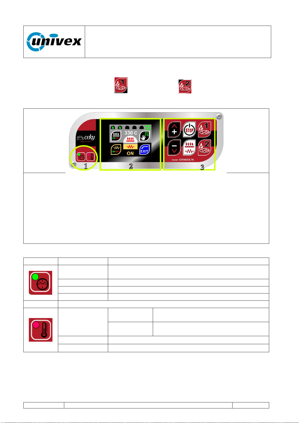
Fig. 8.1.1. Operator Interface Panel
All settings and operating information of the oven are available in the operator panel and
include:
1. LED signal lights. They notify the operator on the oven's operating status.
2. Display touch screen. Device with a graphic interface that allows the user to see
the oven's operating conditions and to interact with its operation through the use of
the graphic keys proposed by the display (operation is activated by touching lightly
the graphic).
3. TOUCH function keys (rapid function). Activates some specific working functions
of the oven.
Fig. 8.1.2. LED signal lights in two colors (red or green)
Icon
Signal status
Description
Solid red
Electronics OFF, sheated element, baking deck rotation
and burner OFF (only the mains supply tension is ON);
Flashing red
Deck is still.
Solid green
Deck is rotating.
OFF
Equipment is not powered.
Solid red
When the
oven is on
“BAKING 1” or “BAKING 2” cycle on
going
When the
oven is off
Equipment is powered and in stand-by
Green
Program complete
Off
Equipment is not powered
“ROTANTE” pizza oven
R-002 100218
Page 27 of 43
8.2 First startup of the oven
First Level Operator: the operator, with no specific skills, who is able to use the
equipment in normal working condition and for simple maintenance
interventions.
Once the oven has been correctly installed, before starting it up for the first time the user
should first operate a pre-heating cycle in order to remove water residue inside the
concrete mix used in the baking chamber by taking the following steps:
phase 1. Heating of the baking chamber at a temperature of 100°C for a duration of
16 hours (2 working days);
phase 2. Heating of the baking chamber at a temperature of 200°C for a duration of
16 hours (2 working days);
phase 3. Heating of the baking chamber at a temperature of 300°C for a duration of
16 hours (2 working days);
During the pre-heating phases, the water vapour generated by the
concrete can lead to water dripping around the area occupied by the oven.
We also inform you that this event can in some cases occur for several
months since the first time the oven is operated.
The operating guidelines for the oven's first startup are available here below.
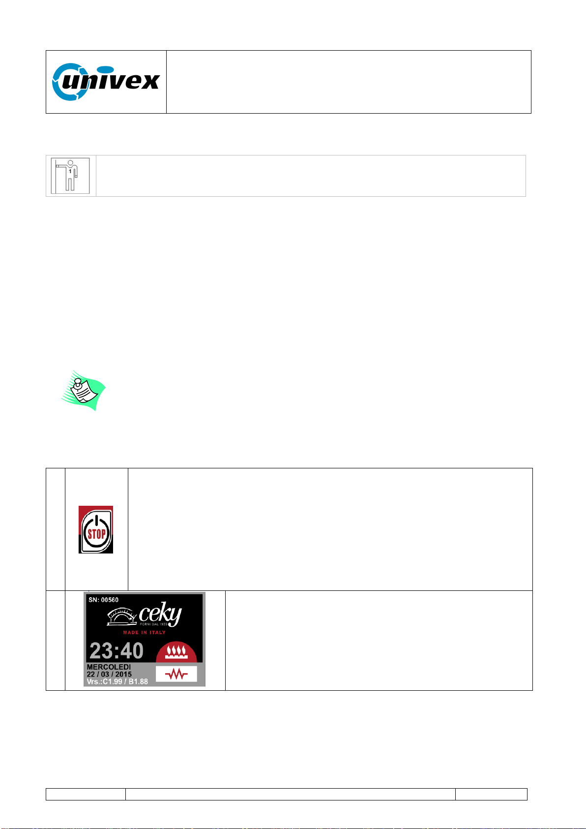
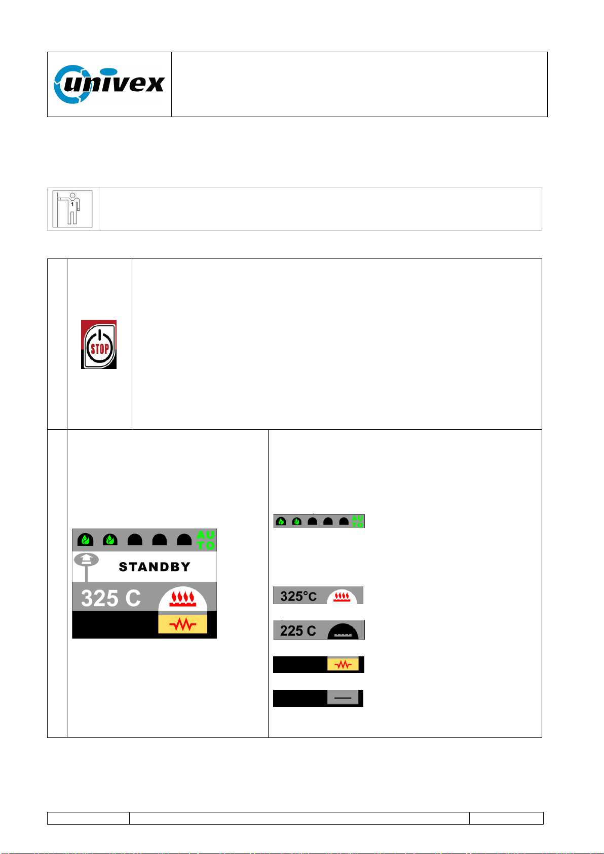
1
ON/OFF-STOP key
The key activates different functions according to the equipment's status:
With the equipment turned off: PI activates the mains supply power to the
oven. The engine rotates, heating sheated elements OFF and burner
turned off
Wit the equipment turned on PM the equipment turns off.
2
Image shown when starting the machine. After some
seconds the display will show the next page.
This page displays important information such as:
- The equipment's serial number (SN: 00560)
- Hour and date (23:40 WEDNESDAY 22/03/2015).
- Program version of the console and bedplate (Vrs.:
C1.99 / B1.88)
“ROTANTE” pizza oven
R-002 100218
Page 28 of 43
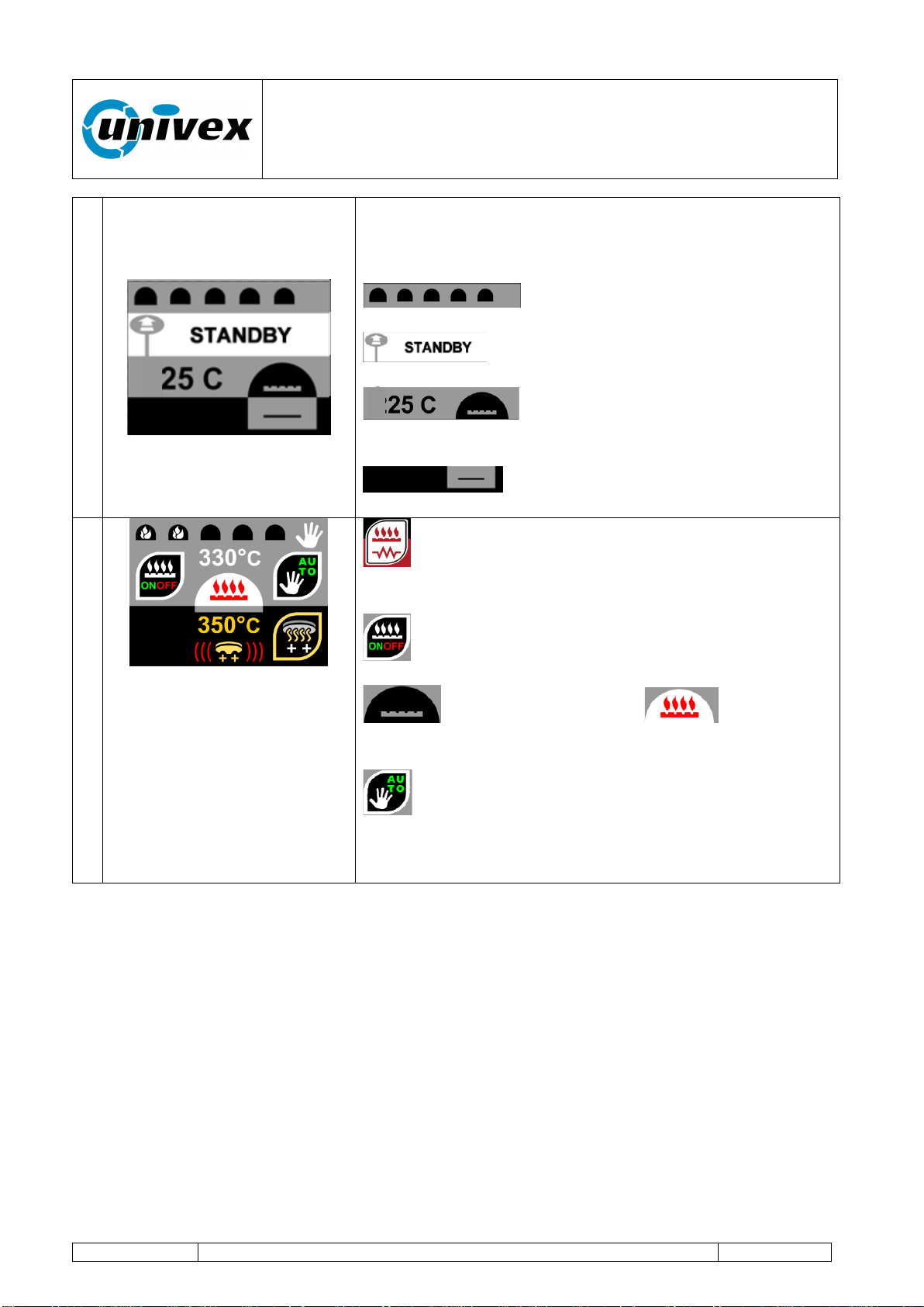
3
After a few seconds the display shows the "STANDBY"
page which includes information on the current status of
the oven.
Burner flame level (turned off)
Oven status information
Baking chamber temperature with
Image of the burner OFF
Image of the Sheated element being
OFF
4
TOUCH key burner-sheated element the display
shows the heating control page.
Burner graphic key ON-OFF. Turn on-off the
burner.
burner turned off (OFF) burner
turned on (ON)
With the graphic key auto/man select the
automatic function.
With the function keys + / - set the baking temperature to
100°C (phase 1).
At the end of the phase 1 you move to the next phases with a similar mode of action.
“ROTANTE” pizza oven
R-002 100218
Page 29 of 43
8.3 Normal operation
Once the first startup phase is over and the optimum temperature is reached, the oven is
ready for normal operation.
First Level Operator: the operator, with no specific skills, who is able to use the
equipment in normal working condition and for simple maintenance
interventions.
The following description illustrates the normal operating sequences.
1
ON/OFF-STOP function key
ON/OFF-STOP key functions (with the equipment turned off):
PM (ca. 2 seconds) enables the supply mains power to the
oven (the equipment turns on and displays the operating
conditions that were active before it was turned off).
ON/OFF-STOP key functions (with the equipment turned on):
PI stops only the engine rotation, the next PI will re-start the
engine;
PM (ca. 2 seconds) turns off the oven.
2
Some seconds after startup, the display shows
the STANDBY page. The display shows the
status information about the main oven’s
parameters.
Specifically, the figure shows the following
information.
Automatic operating mode with
increasing flame level. (the mode can be
switched from auto to manual changing the
flame color displayed)
Baking chamber temperature
with burner icon ON.
Baking chamber temperature
with burner icon OFF.
Sheated element status:
sheated element icon ON.
Sheated element status:
sheated element icon OFF.
“ROTANTE” pizza oven
R-002 100218
Page 30 of 43
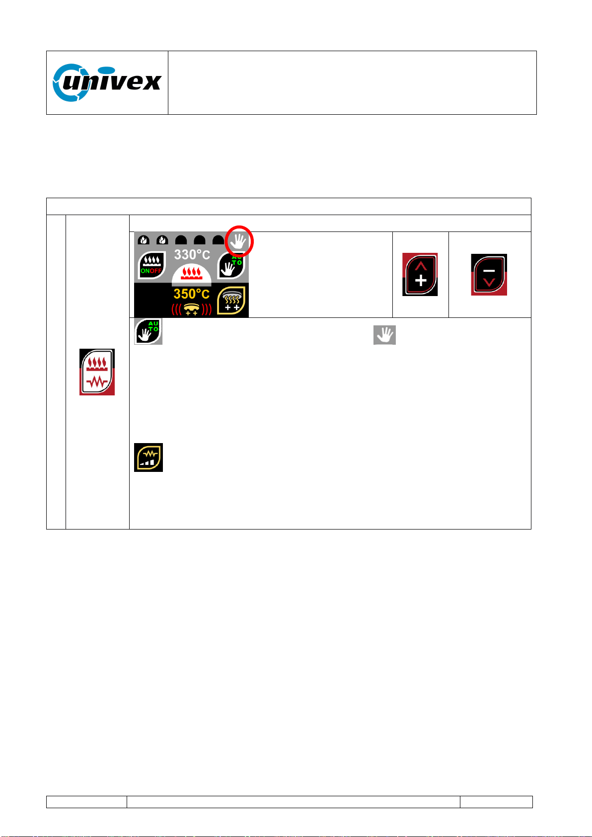
8.3.1 Manual operating mode.
Operating condition for the oven to maintain or reach the baking chamber temperature at
the desired value manually.
Working in this mode allows the user to directly control flame’s height.
It is enabled with PI TOUCH key burner-sheated element from the STANDBY page.
1
TOUCH key burner-sheated element
Graphic key. Selects the Manual mode: is displayed in top right
corner. With function keys + and - the operator sets the burner's flame
level. The flames displayed at the top of the screen will be white. With
this mode on, the temperature control is not enabled. Pressing + or –
function keys will change the number of flames displayed on the top of the
display from a minimum of 1 to amaximum of 5 flames. The flame’s height
inside the chamber will vary accordingly.
Graphic key. Activates or deactivates the deck's heating sheated
element (the status conditions is shown on the display). Check the
sheated element control chapter for more information
With the graphic key EXIT the STANDBY page is shown.
“ROTANTE” pizza oven
R-002 100218
Page 31 of 43
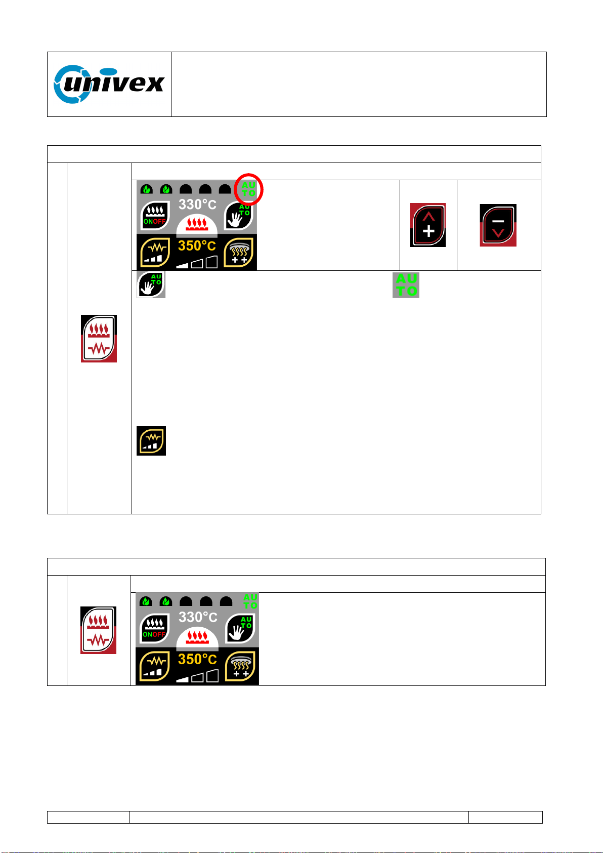
8.3.2 Automatic operating mode.
It is enabled with PI TOUCH key burner-sheated element from the STANDBY page.
1
Graphic key selects the Automatic mode: icon is displayed on
the top right corner of the status display. With the function keys + and –
the operator sets the desired temperature level for the baking chamber.
The flames displayed at the top of the screen will be green. With this
mode on, the temperature control is enabled and the flame will
automatically be managed by the system to reach and maintain the
requested temperature.
Keeping + or – function key pressed for more than 2 seconds will increse
the variation speed.
Activates or deactivates the deck's heating sheated element (the
status conditions is shown on the display). Check the sheated element
control chapter for more information
With the graphic key EXIT the STANDBY page is shown.
8.3.3 Sheated element control and setup
It is enabled with PI TOUCH key burner-sheated element from the STANDBY page.
1
From the STANDBY page TOUCH key burner-sheated element
“ROTANTE” pizza oven
R-002 100218
Page 32 of 43
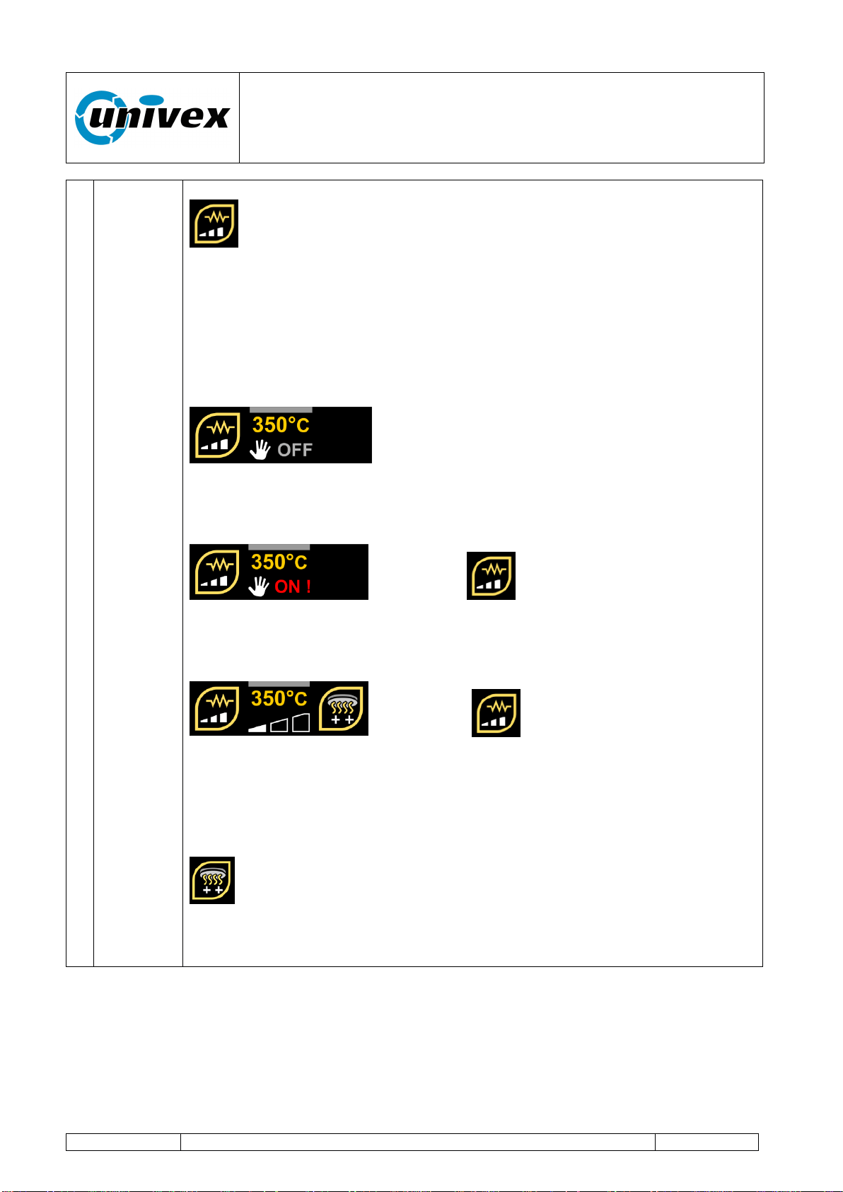
Graphic key switches the baking chamber's heating sheated
element status. The operating condition will be shown on the display.
The actual temperature is displayed in yellow above the status indicator.
The displayed temperature does not indicate the cooking deck’s
surface temperature. The measurement is taken from the area below the
deck and is mainly used for the probe to regulate the automatic start/stop
cicle (description below).
The sheated element status is displayed on the
bottom part of the display and shows the sheated element behaviors
according to the user’s settings. The sheated element will be set OFF as a
default option.
Pressing the graphic key once will change
the status to ON. In this status the sheated element will always be powered
until its status is manually changed. No thermostatic control is applied to
the sheated element.
Pressing the graphic key again will change
the status to AUTOMATIC. This status has 3 different levels that help the
computer to determinate the Start/stop cycle for the sheated element.
Different parameters are taken into account to regulate the cycles and
higher regulation levels will increase the sheated element impact on the
deck’s temperature.
Graphic key will be displayed when AUTOMATIC mode is on.
Pressing this key will immediately start the sheated element for a fast pre-
heating cycle. It is used to help fast start the deck heating process at the
beginning of the work session.
“ROTANTE” pizza oven
R-002 100218
Page 33 of 43
8.3.4 “BAKING 1” and “BAKING 2” programs.
The oven works as per the operating settings stored in the “BAKING 1” or “BAKING 2”
programs.
The baking process is regulated with user-customized level values for the burner's flame,
duration and deck's rotation speed.
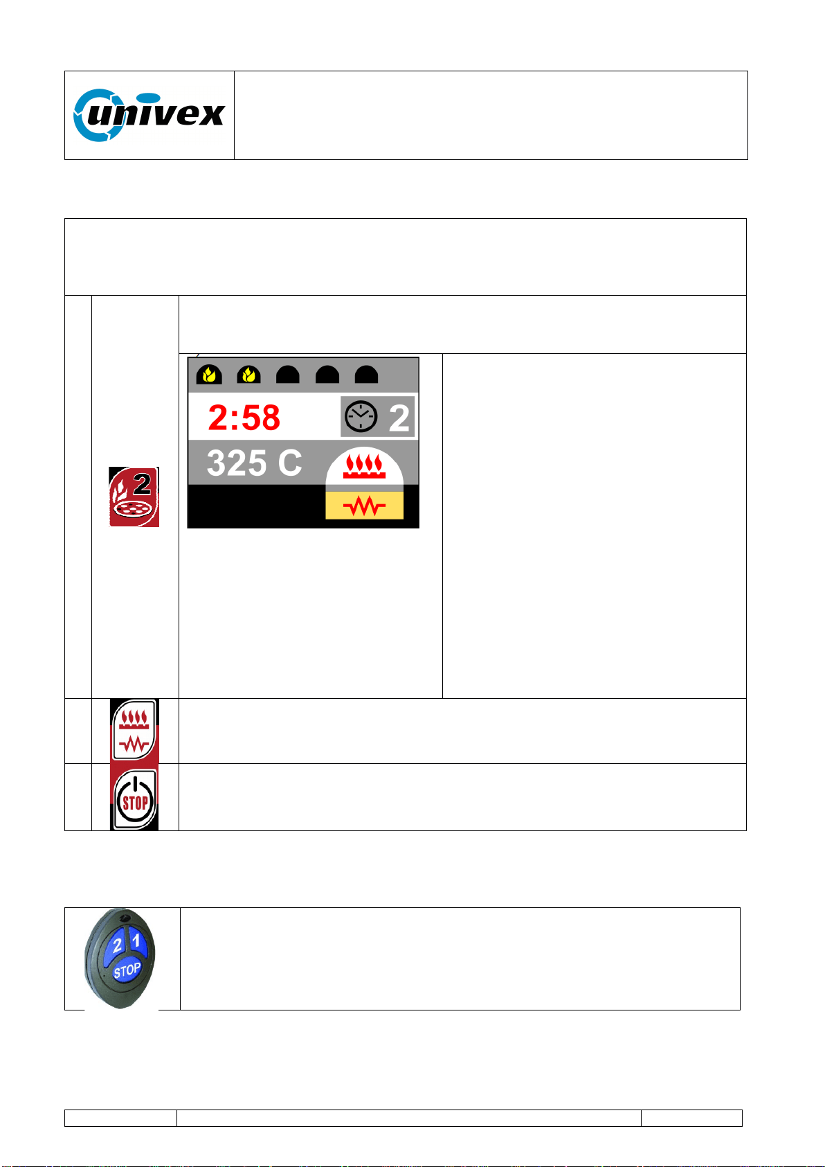
1
Pressing the “BAKING 2” function starts its specific baking program.
The pre-stored values are applied: flame level, baking time, deck rotation
speed and final speed.
While the program is on, the display
will show the oven's current operating
conditions.
A. Burner's flame level.
B. Remaining baking time. The
operator can increase or decrease
the baking time using the function
keys +/- with intervals of 10
seconds.
C. Temperature of the oven.
D. Temperature of the deck (sheated
element turned on)
With PI “BAKING 1” key you can
interrupt or restore the baking program.
With PM “BAKING 1” key you activate
the Program complete procedure.
2
Pressing the burner control key will allow to manually change the flame
level during the baking program. This change will only influence the actual
program’s values and no changes will be applied to the stored program.
3
STOP key
- PI the deck rotation stops, PI again to restart rotation.
The operating modes of the “BAKING 1” function keys are totally similar to the “BAKING 2”
key modes.
For ease of operation, the system's control electronics is equipped with a
remote control that enables the following functions:
- “BAKING 1” function key (key 1)
- “BAKING 2” function key (key 2)
- STOP function key (stops the baking deck rotation).
A
B
C
D
“ROTANTE” pizza oven
R-002 100218
Page 34 of 43
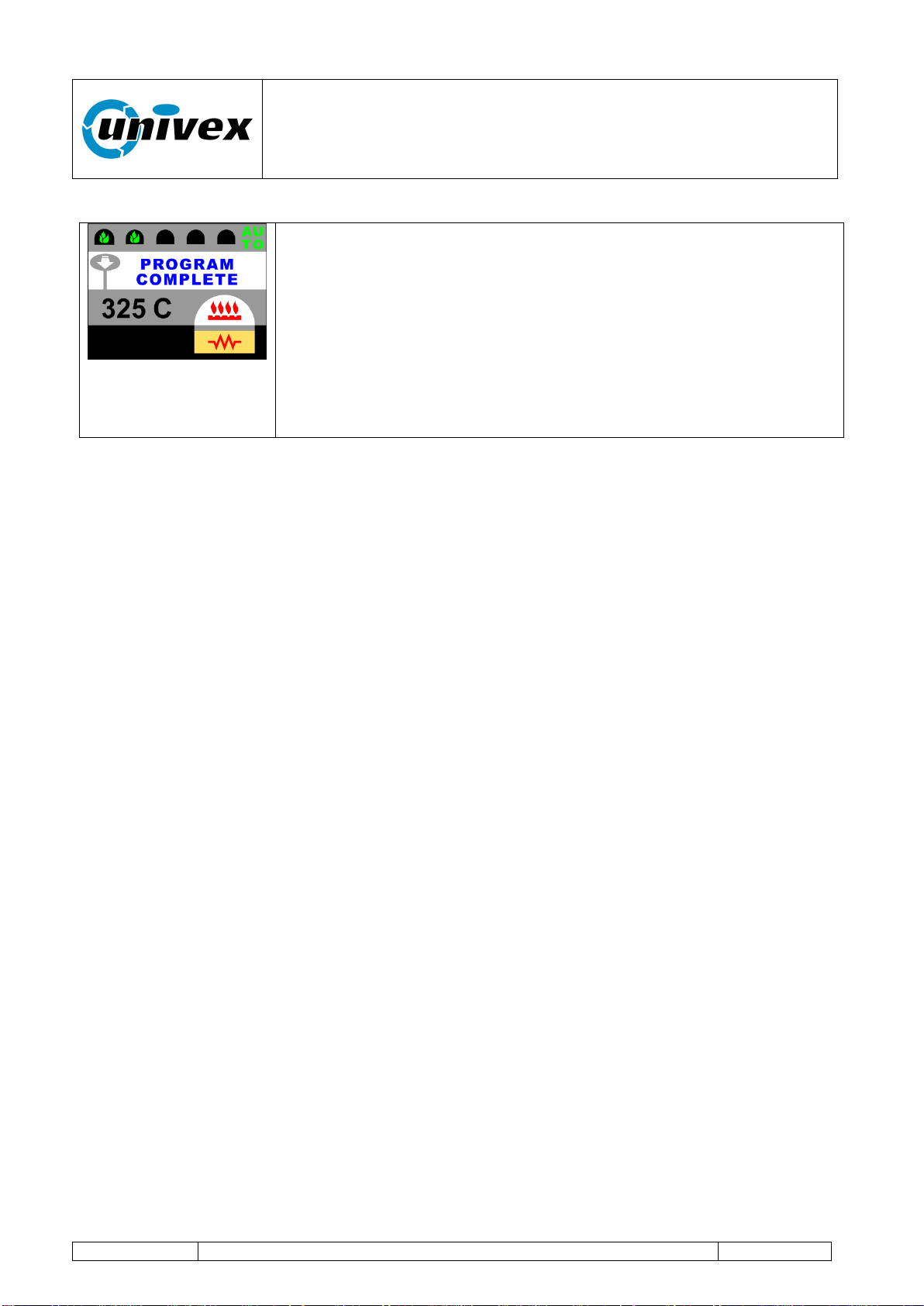
8.4 Program complete.
The oven's operating mode upon baking time completion or upon
the operator's request, it activates an audible signal during
approximately 4 seconds which is followed by a temporary
reduction in the deck rotation speed.
The oven’s speed reduction is configured in the respective
program’s settings (see the following page, #fn 3 and 7
Speed reduction time is set by the oven's general configuration
parameter (see the paragraph Setting parameters for the oven's
general configuration).
“ROTANTE” pizza oven
R-002 100218
Page 35 of 43
9. Setting parameters for the oven's general configuration.
The control electronics allows the user to customize all the oven's operating parameters.
During the configuration phase, the oven keeps the preceding operating
status. Unless otherwise specified, the configured changes are immediately
active.
Access to configuration logs is enabled from the STANDBY page with PM (keep the button
pressed) of the function key [+].
In this condition it is possible to scroll through the parameters you want to change using
the keys [+] and [-].
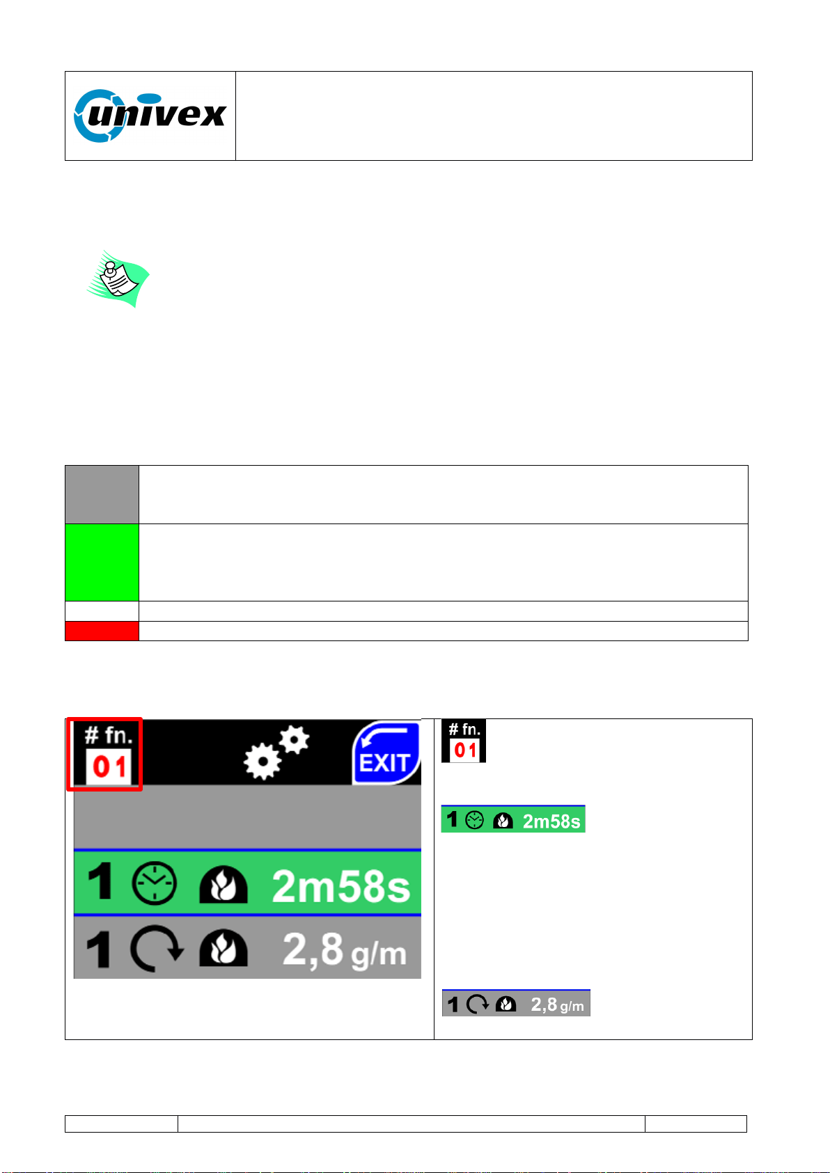
For the ease of operation, the display shows information with lines of different colors
associated with different functions:
GRAY
The line with a gray colored background shows some information about the
oven's operating status and these cannot be modified until selected by the
operator.
GREEN
Line with a green colored background. The parameter shown on the display can
be changed by the operator. By touching the line, the background's color will
change from green to white, the operator can change the parameter indicated in
the area with a red colored background.
WHITE
The line with a white colored background allows the operator to make changes.
RED
Areas with a red background - parameter can be modified.
The setting modes are described here below.
Home screen
Identification number of the line
associated with the single parameter to
be set.
Editable parameter.
Selected line (in green) - by pressing it
the background color will change to
white, the stored parameter can be
changed using the function keys +/-, the
OK key ends the modification process,
otherwise use the CANCEL key to exit
the setting (without making any change).
Non editable
parameter (until selected).
“ROTANTE” pizza oven
R-002 100218
Page 36 of 43
#fn
01
Time control of the BAKING 1 cycle (from 0.1 sec. to 99 minutes and 59 sec.)
02
Speed control of the baking deck rotation during the BAKING 1 cycle (from 0.5 to 5.5
rounds per minute) in RPM
03
Speed control of the baking deck rotation during the PROGRAM COMPLETE
BAKING 1 phase (from 0.5 to 5.5 rounds per minute) in RPM
04
Flame level control during the BAKING 1 cycle (range 1-5)
05
Time control of the BAKING 2 cycle (from 0.1 sec. to 99 minutes and 59 sec.)
06
Speed control of the baking deck rotation during the BAKING 2 cycle (from 0.5 to 5.5
rounds per minute) in RPM
07
Speed control of the baking deck rotation during the PROGRAM COMPLETE
BAKING 2 phase (from 0.5 to 5.5 rounds per minute) in RPM
08
Flame level control during the BAKING 2 cycle (range 1-5)
09
Speed control of the baking deck rotation when in STANDBY MODE
10
Time control for the PROGRAM COMPLETE phase (range 0,1 sec. to 99 minutes
and 59 sec.)
11
Setting the rotation direction of the baking deck: clockwise or counterclockwise
NOTE: The changes will take place only after the deck has been stopped and
restarted with PI STOP ON-OFF button
12
Temperature display setting in Celsius or Fahrenheit scale.
13
Language setting for the displayed texts (Italian – English – etc.)
14
Remote controls pairing (max. 3). Select a position from 1 to 3 and press on the
screen. Press any button on the remote control to complete the pairing procedure
15
Firmware UPDATE function. Operation conducted using a USB pen drive and
following the information shown on the display. Insert USB key containing the fw
update file in the slot, prior to selecting this option
16
Auto-control setting for the burner's flame minimum level (flame 1). The wizard is
launched. This function can only control the levels managed by the MODUPLUS®
within the ranges mechanically set. To change minimum and maximum levels refere
to paragraph 7.4.1 - Setting minimum / maximum gas levels
If the wizard stops before completing the operation, the previously recorded setting
will be restored.
17
Oven internal light mode:
On
Off
18
Factory setup: remote guided assistance will be needed in order to access this
menu. +39(0)30.9972249 to call the technical support center. Only an authorized
Univex operator can ask you to modify the parameters within this menu.
“ROTANTE” pizza oven
R-002 100218
Page 37 of 43
10. MAINTENANCE
During the operation and even after a long time after turning the oven off,
the cooking chamber will remain HOT. Consider this while leading any
maintenance inside the oven.
The operations described in the following paragraph should always be
carried out with the equipment turned off (equipment disconnector set to
OFF).
The user should regularly clean the equipment's external covering using a
soft cloth moistened with neutral and non-aggressive detergents, and then
wipe off with a dry cloth.
10.1 Daily maintenance
Remove any residue from the oven floor using a vacuum cleaner, a broom, a soft bristle
brush or similar tools. Conduct the operation when the oven is turned off and with no
flame inside the baking chamber, making sure that the electrical sheated element under
the baking deck is off.
Do not use water or detergents to clean the oven's baking deck or any
internal part of the oven.
10.2 Periodic maintenance
Recommended time interval: once a week
Before each periodic maintenance, disconnect the oven from its power
supply, making sure that the standby red led signal on the control console
is turned off.
Type of intervention:
Remove the baking residue in the area under the rotating deck:
First Level Operator: the operator, with no specific skills, who is able to use
the equipment in normal working condition and for simple maintenance
interventions.
First Level Operator: the operator, with no specific skills, who is able to use
the equipment in normal working condition and for simple maintenance
interventions.
“ROTANTE” pizza oven
R-002 100218
Page 38 of 43
Remove the locking screws on the front part of the oven landing and pull out the first
section of the oven landing by sliding it outwards. Disconnect the contact wires to the
safety thermostat on the left and pull the metal oven landing out by sliding it outwards.
When pulling it out, please pay special attention to the electrical sheated element making
sure you don't break or tear anything apart.
Once the 2 oven landing sections have been removed, you can start cleaning the wall
clearance under the baking deck using a vacuum cleaner, a broom, a soft bristle brush or
similar tools.
Once you finished cleaning, put the oven landing back in place and re-connect the
thermostat on the left. Insert also the front part of the oven landing and tighten again the
front locking screws.
Recommended time interval: once every 2 years
Manufacturer's Technician: the qualified technician who has been designated
by the manufacturer to carry out complex operations in specific situations or, in
any case, on the basis of what has been agreed upon with the user. Depending
on each case, the personnel is requested to have mechanical and/or electrical
and/or electronic and/or IT skills.
Type of intervention: Cleaning and maintenance of the gas burner, combustion adjustment
and control.
Type of intervention: Greasing the beads below the rotating deck. Accessing the 2 beads
positioned below the deck, from the bottom of the oven, add some grease in order to allow
a proper and smooth rotation of the mechanical components.
Recommended time interval: once every 10 years
Manufacturer's Technician: the qualified technician who has been designated
by the manufacturer to carry out complex operations in specific situations or, in
any case, on the basis of what has been agreed upon with the user. Depending
on each case, the personnel is requested to have mechanical and/or electrical
and/or electronic and/or IT skills.
Type of intervention: Inspection and adjustment of the baking deck and internal dome.

“ROTANTE” pizza oven
R-002 100218
Page 39 of 43
11. INCONVENIENCES AND ANOMALIES
id
VISIBLE
CODES
DESCRIPTION
B
R
ACTION
2
22
Burner block for spark failure
YES
NO
Check gas, electrodes or
220V inversion + RESET
(see below)
2
25
Burner block for false flame
signal at startup
YES
NO
Turn the oven off RESET
(see below) and restart
2
27
Burner block for losing the
functioning flame signal
YES
NO
Check the burner electrodes
and if gas is flowing +
RESET (see below)
2
29
Burner block due to fault inside
the valve
YES
NO
Contact customer support
2
2C
Burner block due to fault inside
the valve
YES
NO
Contact customer support
2
2D
Burner block due to fault inside
the valve
YES
NO
Contact customer support
2
2E
Burner block due to fault inside
the valve
YES
NO
Contact customer support
2
2F
Base-Valve communication
broken
YES
NO
Check the valve cable and/or
contact customer support
3
31
Temperature PROBES circuit
error (X0 reading)
@
NO
Send to customer support
3
32
Temperature PROBES circuit
error (X1 reading)
@
NO
Send to customer support
3
34
Error reading J1 probe (oven)
@
NO
Check if J1 probe can be
operated
3
38
Error reading J2 probe (base-
subplate) [§]
@
NO
Check J2 probe (change to
OFF if absent)
3
3C
J probes general error:
@
NO
Check if J1 and J2 probes
can be operated
3
30-31-32-
33-35-36-
37-39 -3A -
3B -3D
Temperature probe circuit critical
errors
@
NO
Send to customer support
4
40
Error reading board internal
temperature
@
NO
Send to customer support
“ROTANTE” pizza oven
R-002 100218
Page 40 of 43
4
41-42-43-
44-45-46-
47-48-49-
4A-4B–4C-
4D– 4E- 4F
Temperature probe circuit board
general errors
@
NO
Send to customer support
6
64-65-66-
67-68-69
Wiring board internal error
YES
YES
Serious error - contact
customer support
6
6A-6B-6C-
6D
Wiring board overflow parameter
YES
YES
Serious error - contact
customer support
7
70
Internal clock failure or
low/missing battery
YES
YES
Serious error - contact
customer support
7
71
Deck overheating notice
NO
NO
Sheated heating element is
on and the deck is not
rotating. Turn off the elec.
sheated element or restart
deck rotation.
F
F0
Base-Console communication
broken
YES
YES
Serious error - contact
customer support
[§] = If “Sheated element” is set to “OFF” (Manual) there's no error reported
B = Burner blocked R = Deck Rotation blocked
@ = It can be also used with burner in manual mode
RESET = Manual resetting of the gas burner. In order to reset, press and hold the red
button next to the console for 2 seconds and release it. The displayed error will
disappear and you can try again to start it up.
If the suggested operation did not solve the malfunctioning, interrupt the
operation and ask for help to the customer support center.
Do not open the equipment's external covering if you're not expressly
authorized in writing by Univex. The non-observance to this rule will lead
to the immediate invalidation of the warranty and of the retailer's
ensuing responsibilities for aspects concerning safety and functioning.
“ROTANTE” pizza oven
R-002 100218
Page 41 of 43
12. INTERVENTION REQUEST FORM - REPLACEMENT PARTS
Dear:
Univex Corporation
3 Old Rockingham Road
Salem NH, 03079
Tel.603-893-6191
Date __________________.
REPLACEMENT PART ORDERING - FAULT REPORTING - INFORMATION FORM
Client:
Model
Location
Code
Address
Serial n.
Telephone
Fax:
Sent by
Replacement part ordering table:
Product code
Qty
Notes
_________________________________
APPLICANT'S STAMP AND SIGNATURE
Technician visit requested for the following faults:
Fault notes or description
“ROTANTE” pizza oven
R-002 100218
Page 42 of 43
13. REPLACEMENT PART LIST
Product description
Product code
Rotating deck heating sheated element
XRES6U
Deck rotation engine
XMTU018
Gearbox 1
XRDT40
Gearbox 2
XRDT90
“Giravolta” touch screen control panel
YPNLGRV/U
Oven lamp (internal led only)
YCBLAMP
Lamp bloc (lamp, lamp-holder, Pirex glass, metal lamp-holder and
wiring)
YLIGHT
Flame detection electrode
ZELETRIV
Startup electrode
ZELETACC
Gas valve, including gas modulator
ZVK410
Gas valve safety and control module
ZS456
Reset button
ZPLSLUM
14. ATTACHMENT LIST
This manual also includes the following documents:
Type of document
Code
Electrical wiring scheme
Univex-Rotante-scheme-USA.pdf

“ROTANTE” pizza oven
R-002 100218
Page 43 of 43
15. WARRANTY
16. WARRANTYCONDITIONS AND RESTRICTIONS:
Univex guarantees the product for a period of 12 months. The warranty becomes effective
as per the purchase date indicated on the invoice when the equipment is delivered. Univex
agrees to repair or replace without charge all parts within the warranty period if they fail due
to a manufacturing defect. The warranty does not include any form of compensation
resulting from direct or indirect damages to persons or things. As long as the warranty is
effective, if the Client desires that the repair should be carried out by Univex technicians,
they should send a written request to Univex. In this case, they will also take charge of all
the costs associated with travel, board and lodging. For interventions due to defects or
faults that are not clearly linked to materials or manufacturing, all costs deriving from
travels, repair and/or replacement of all parts will be charged to the buyer. The warranty
cannot be extended after a repair intervention is carried out on the equipment. In case
parts of the equipment are returned, the Client can make the shipment only after receiving
the written authorization from Univex. Costs of packing and shipping are charged to the
client (unless the parties agree otherwise). In any case, the warranty does not cover
accidental damages resulting from transportation, negligence, inappropriate use, non-
compliance with the instructions described in this manual, and from any event that does not
depend on the normal operation or use of the equipment. The warranty expires if the
equipment is repaired by non-authorized third parties or if you use tools or accessories that
are not provided, recommended or approved by Univex, or in case the registration number
is removed or altered during the warranty period. The warranty ceases immediately to be
effective upon default or delay in payment. Univex declines any responsibility for any
damages to persons or things resulting from the wrong or inappropriate use of the
equipment.