
CONTENTS
N OTICE............................................................................................................................2 EN
TROUBLESHOOTING........................................................................................................2 EN
WHAT'S IN THE BOX.........................................................................................................2 EN
PRODUCT TECHNICAL DATA ........................................................................................3 EN
PEODUCT DIMENSIONS..................................................................................................4 EN
INSTALLATION
INSTRUCTIONS.........................................................................................4 EN
THE SPEAKER WIRING IN NORMAL MODE ...................................................................5 EN
THE SPEAKER WIRING IN BRIDGE MODE .....................................................................5 EN
INTRODUCTION ..............................................................................................................6 EN
SOFTWARE INTRODUCTION ..........................................................................................8 EN
1 EN
2 EN
INTROUCTION AND TROUBLESHOOTING
WHAT'S IN THE BOX
NDSR350A 1pc
User Manual 2pcs(1 Chinese, 1 English)
USB2.0
Mounting brackets
Cable(1.5m) 1pc
Mechanical round head screws (PM3*6mm) 8pc
4pc
Self-Tapping Oval Head Screws(PA4*40mm)
4pcs
Velcro 2Prs
1. To prevent short circuit, please keep the device away from water or damp places.
2. If water or any other liquid enters the device, cut off the power immediately, and inform
the nearest Nakamichi Service Center or Agent to inspect the product.
3. Users are not recommended to disassemble the device as there are no user serviceable
parts inside, please contact the nearest Nakamichi Service Center if necessary.
NOTICE
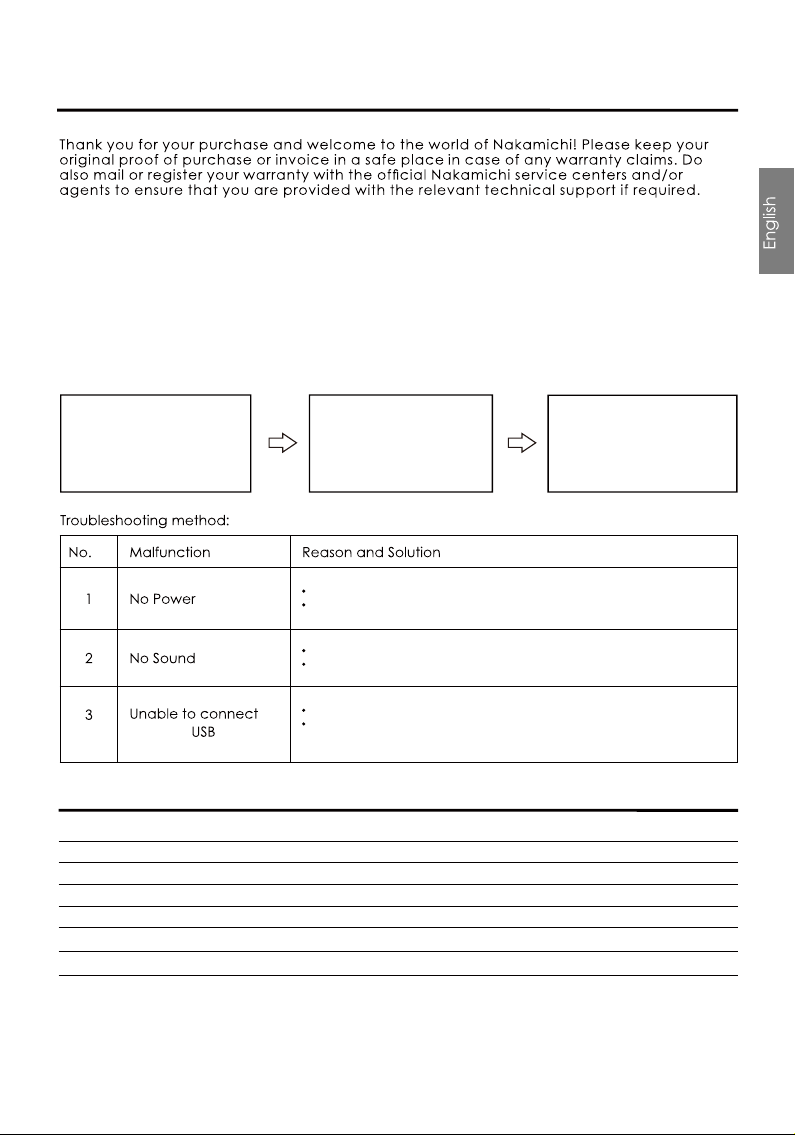
When it is still not
repairable after
inspection:
Please return the unit to
factory settings.
Please consult the
nearest service center or
authorized agent for
further aptions.
Still unable to repair:
Ensure all cables and prts are securely connected before turning on the power.Shown
below is the basic troubleshooting procedure that you should follow.
TROUBLESHOOTING
When a failure occurs:
Before sending the unit
for repair, please refer to
the table for common
troubleshooting solutions.
Check the power connection and make sure it’s sucure.
Check the ACC connection and make sure it’s secure.
Double check if the unit is in MUTE mode.
Check if you have choose the correct input channel.
Check the USB connection and make sure it’s secure.
Check if the driver “HID-compliant device” has been
properly installed in your PC.
through
3 EN
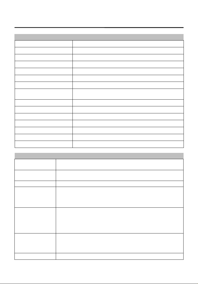
PRODUCT TECHNICAL DATA
Product Data
Dynamic Range(RCA Input)
≥100dB
S/N (RCA Input)
≥98dB
THD
≤
≤
0.05%
Frequency Response
20Hz~ 20KHz
Input Impedance
High Level :51Ω
Low Level Output Impedance
51Ω
Signal Input Range
RCA:7.5Vpp; High Level:26Vpp
Signal Output Range
RCA:7.5Vpp; Amplifier Maximum Power :
2CH×80W(Bridging 1×160W)+4CH×40W+4CH×25W
Working Temperature
-20~ 70
℃
Power
DC 9V~15V
REM Input
High Level Input Signal:H1+/H1- or ACC control cable
REM Output
+12V Start up Voltage Output(0.1A)
Standby Power
0.1W
Net Weight
Approx. 2.24kg
Product Dimension
217(L) *186(W) *48(H)mm
Technical Sheet
Input Type
6 Channels High Level, 2 Channels Low Level, Built-in and external
digital Bluetooth, Optical /Coaxial
Output Type
12 Channels Low Level, 2CH×80W(Bridging 1×160W)+4CH×40W
Output Gain Gain Range: Mute,-59.9dB ~ 0.0dB
Output Signal EQ
31 Band Equalizer Engine :
1. Frequency range: 20Hz ~ 20KHz, 1Hz Accuracuy
2. Q value (slope): 0.404 ~28.852
3.Gain: -12.0dB ~ +12.0dB, 0.1dB Accuracuy
Output Signal
Crossover
Each output is equipped with multi-order high and low pass
independent filters.
1. Filtering types: Link-Ril, Butter-W, Bessel
2. Filtering frequency division point: 20Hz ~20KHz. Resolution 1Hz
3. Filter slope (slope) setting: 6dB / Oct to 48dB / Oct and OFF
Output Phase and
Time Alignment
Each output channel can be adjusted for phase and delay, parameter
range:
Phase: in-phase or reverse-phase (0゜/180゜)
Delay: 0.000 to 20.000ms, 0 to 692 cm
,
0 to 273 inch
Presets 6 Presets into the device
+4CH×25W Power
4 EN
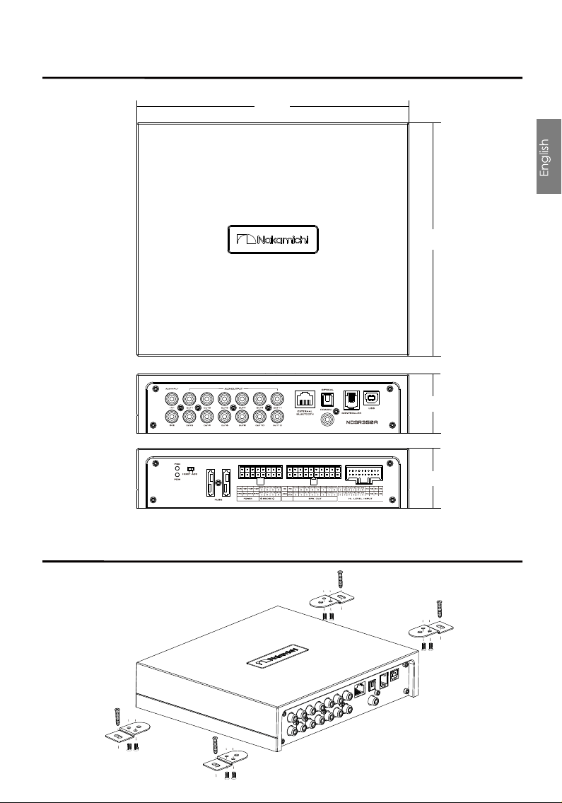
PEODUCT DIMENSIONS
INSTALLATION INSTRUCTIONS
2 17m m
186 mm
48 mm
48m m
5 EN
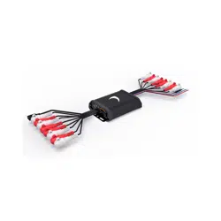
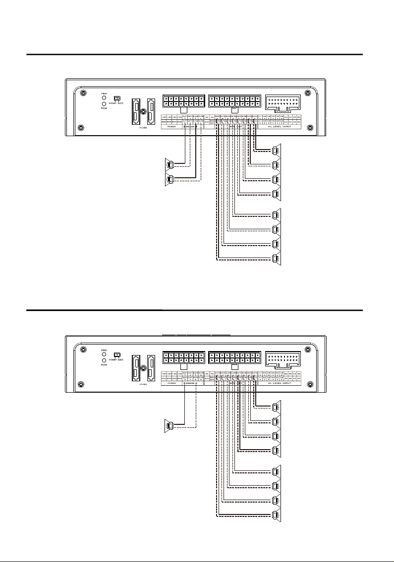
THE SPEAKER WIRING IN NORMAL MODE
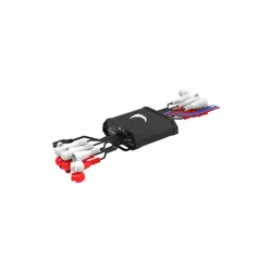
THE SPEAKER WIRING IN BRIDGE MODE
2×80W (4 )Ω
4×25W ( 4 )Ω
4×50W ( 4 )Ω
4× 25W ( 4 )Ω
4× 50W ( 4 )Ω
1×160W(8 )Ω
6 EN
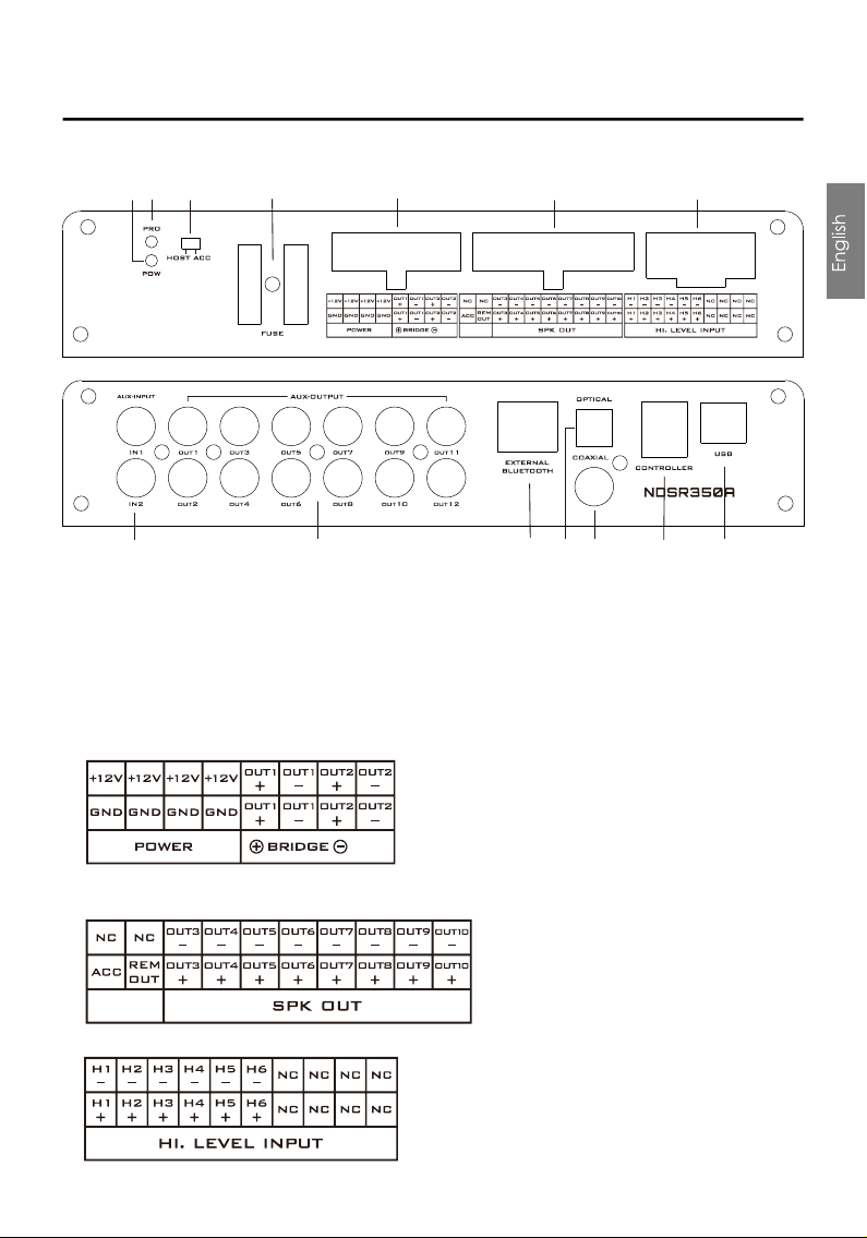
INTRODUCTION
The machine interface diagram is as follows:
3. Machine start mode switch
When the switch is turned to the " ACC" terminal, the machine is started by ACC, and when it is
turned to the "HOST" terminal, the machine is started by the high level H1+/H1- input signal.
2. Protection indicator light
1. Power indicator light
4. The fuse
Two 25A fuses.
5. High level output and power port
1, 2 power amplifier output, can be bridged.
6. High level output port
7. High level input port
3~10 power amplifier output.
1 2
3
4 5 6 7
8
9 10
11 12
13
14

14. USB2.0 Port, Connect to the computer tuning software
No need to download the driver installation, connected to the computer sound software
installed automatically.
8. Low level input port
Connect up to 2 channels low level input.
9. Low level output port
Connect up to 12 channels low level output.
12. Coaxial input port
When the Coaxial input cable of in-car CD or DVD player is connected,the sound source of the
DSP is switched to digital input,and coaxial digital signals can be played.
11. Optical input port
When the optical input cable of in-car CD or DVD player is connected,the sound source of the
DSP is switched to digital input, and optical digital signals can be played.
13. The controller port
Data call and total volume adjustment can be performed by the line controller.
10. External digital Bluetooth input prot
Connect the external Bluetooth, the LED indicator will flash, the indicator will stop flash and will
be always on once you have connected your Mobile phone to the device, then you can play
music in your phone, and the device will change the high level input to Bluetooth Input.
7 EN
INTRODUCTION
a. “+” is positive or positive; “ - ”is negative or inverted (ground).
b. Before connecting the power supply, you must confirm that the power supply meets the
designed power requirements and connect in strict accordance with the equipment
instructions. Otherwise, the equipment may be damaged and may cause accidents such as
fire, electric shock, etc.
8 EN
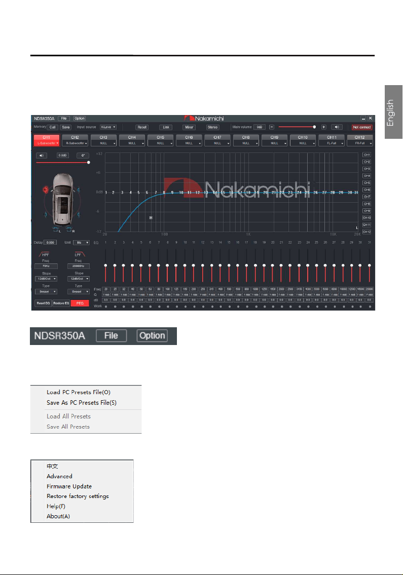
SOFTWARE INTRODUCTION
PC Software Operation Introduction
(PC can be downloaded from the official website (http://www.nakamichicaraudio.com, CONTACT, Downloads))
Computer Configuration Requirements: Screen resolution higher than 1280 x 768, otherwise the
software UI is incomplete, only suitable for windows operation system laptop, desktop and pads.
1. Menu editing area
Main functions: File, options operation.
a. Click the "File" pop-up window, and select to load the scene on you computer, save it as a scene
on you computer, load the whole machine scene or save the whole machine scene.
b. Click on " Option" to select Chinese and English switching, advanced , firmware Update, restore
factory settings, help and about settings.
9 EN
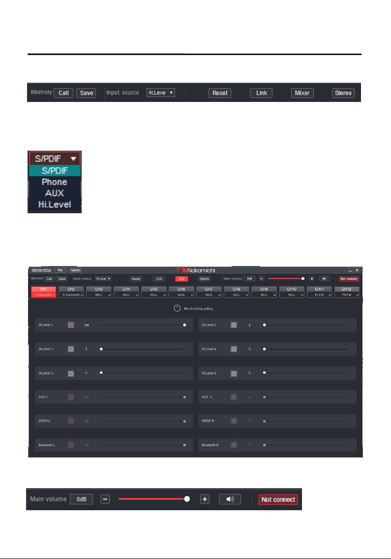
SOFTWARE INTRODUCTION
2. Function editing area
Main functions: scene, master source,mixer source, channel type, link, mixer and mode settings.
a. Scene: 6 sets of scene data can be recalled or stored.
b. Master source: Click the input audio source drop-down list to select the input audio source. There
are S/PDIF, Phone, AUX and Hi.Level.
c. Reset: Click Reset to clear the channel type or restore the default channel type.
d. Link:Click the Link to set the Link synchronization mode: copy from left to right or copy from right
to left.
e. Click "Mixer" to enter the mixing interface, the interface is as shown below.
f. Click "Stereo" to switch between stereo or bridge.
3. Main volume and software connection editing area
10 EN
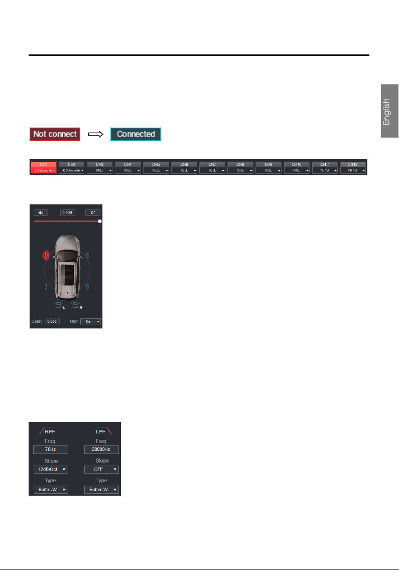
SOFTWARE INTRODUCTION
Main functions: master volume and computer software connection settings.
a. Main volume adjustment range: off, -59dB ~ 0dB. Click the speaker button to mute the main
volume.
b. Click the "Not Connected" button to connect the host with a PC.
4. Output channel type editing area
Main function: configure the type of output channel.
5. Channel delay, volume, phase editing area
a. Push the fader left or right to adjust the sound size, or enter a value or roll the mouse wheel in the
volume input box to adjust the sound size. Click the speaker button to switch mute.
b. Positive phase adjustment: Click [0°]or [180°]to switch between positive phase and reverse
phase.
c. Delay: set the delay value by scrolling the mouse wheel in the delay input box, or enter the value
to set the delay value.
d. Delay Unit button: Click the drop-down list to select milliseconds, centimeters, and inches.
6. Channel divider editing area
Main Function Setup: Channel High & Low Pass Filter Setup.
Adjustable: Filter Type, Frequency point and Q Value (Gradient or Slope).
11 EN
SOFTWARE INTRODUCTION
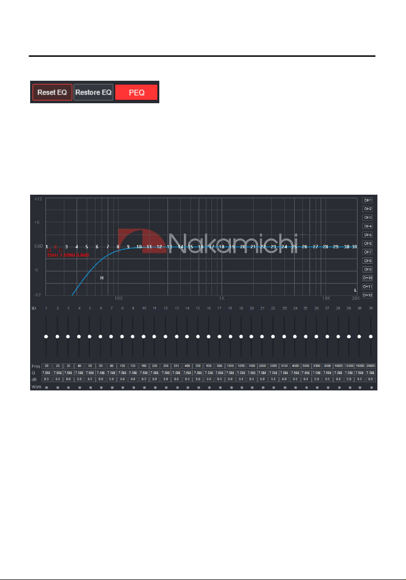
7. Equalizer editing area
a. Reset EQ:It is used to restore the parameters of the all equalizer to the original pass-through
mode (the frequency of the equalizer, the Q value and the gain are restored to the initial value).
b. Restore EQ:Switch between the currently designed equalizer state parameters and the
pass-through mode (the gain of all equalization points is restored to 0 dB, the frequency and
value are unchanged).
c. Click PEQ Mode to switch GEQ Mode.The Q value and frequency cannot be adjusted in the
PEQ Mode interface.
8. Channel EQ editing area
Main function configuration: Equilibrium design of current output channel, 31-band equalization
adjustable: frequency, Q value (response bandwidth) and gain (increasing or decreasing the
frequency response amplitude near the frequency point).
Output
3. Channel interface
Channel high-low-pass crossover setting
with high-low-pass independent filtering.
12 EN
SOFTWARE INTRODUCTION(SMARTPHONE)
Smart-phone Software Operation Instruction
(APP can be downloaded from the official website(http://www.nakamichicaraudio.com, CONTACT, Downloads))
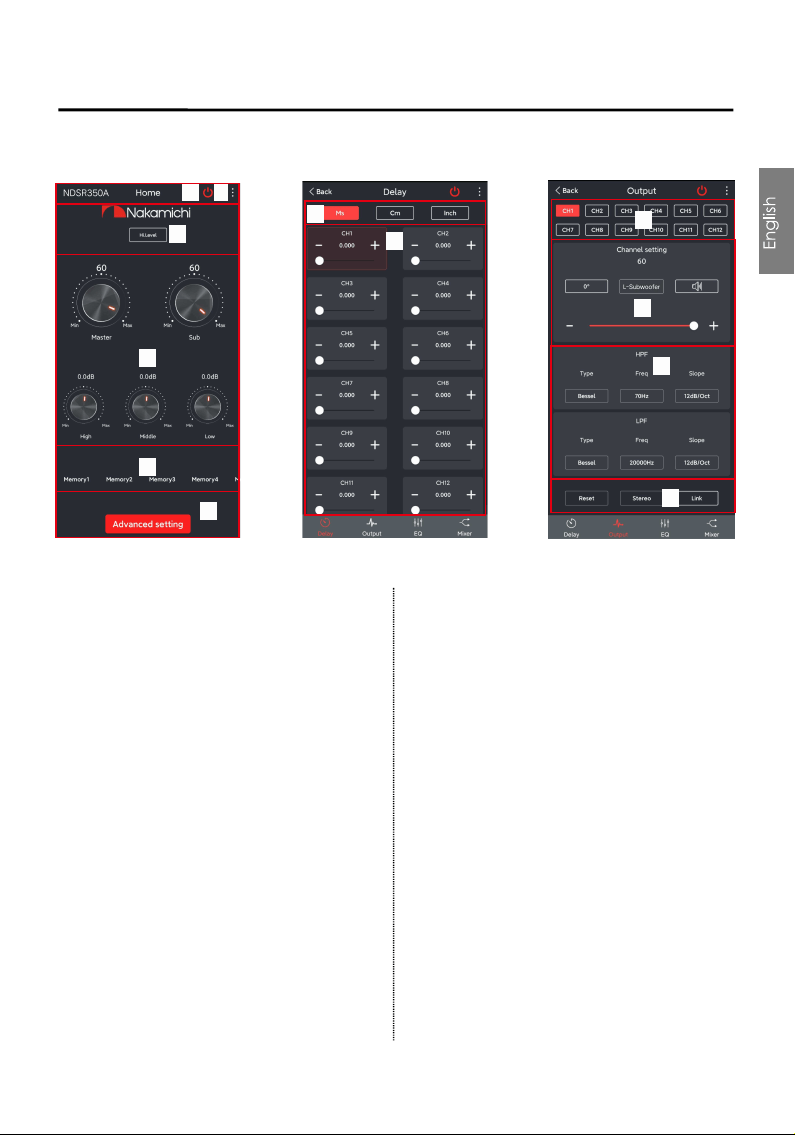
DelayHome
1. Home interface
It can restore factory settings, share sound
effects, save sound effects, turn on local
sound effects, check the model and version
number of the unit, and exit the software
operation; volume, master source, storage
and recall of 6 sets of preset
scenes.
A.Connection Status:
Red means not connected, green means
connected.
B.Menu:
You can restore factory settings, share
sound effects, save sound effects, turn on
local sound effects, view the model and
version number of the machine, and exit the
software operation.
C.Master source:
Master source: S/PDIF,Phone,AUX and
Hi.Level to choose from.
D.Volume adjustment:
Press and hold the volume scale clockwise
or counterclockwise to adjust the volume.
and low volume range is -12dB ~ + 12dB.
The main volume range is 0 ~ 66, The
subwoofer range is 0 ~ 60, The medium, high
E. Scene preset:
There are 1~6 presets to choose from.
F. Advanced settings:
Click [Advanced Settings] to enter the
settings of the delay interface, channel
interface, EQ interface and mixing.
2. Delay interface
Sound field positioning output delay
adjustment.
G.Unit switching:
Switch between milliseconds, centimeters,
and inches.
H.Delay setting:
Click setting window of the corresponding
channel. Slide the dots left and right to set
the delay value. Delay settings can be
made for CH1~ CH12 speakers.
Delay range: millisecond range: 0.000 ~
20.000; cm range: 0 ~ 692; inch range:0~ 273.
L
I
A
B
C
E
D
F
J
K
G
H
Frequency setting: Click the third line
value, and drag the slider bar left and
right in the pop-up dialog box to adjust it.
The adjustment range is 20Hz~20KHz.
13 EN
SOFTWARE INTRODUCTION(SMARTPHONE)
EQ
Adjustable: Filter type, frequency and Q
value (slope or slope).
I.Output channel selection:
Twelve channels are available.
J.Output channel volume setting:
You can adjust the volume by sliding left
and right. The volume range is 0~60. Click
the speaker button to mute.Configurable
output channel type, forward and reverse
switching.
K.Channel divider selection:
Channel type:Choose from Link-Rill,
Butter-W and Bessel.
Frequency Range:20Hz~20KHz.
Slope selection:
6dB/Oct,12dB/Oct,18dB/Oct,24dB/Oct,
30dB/Oct,36dB/Oct,42dB/Oct,48dB/Oct
and OFF can be selected.
L.Joint tuning and channel type settings:
Click [Reset] to reset the output channel
type so that the output type can be
customized.
Click [Stereo] to switch between stereo
mode and bridge mode.
Click [Link] , the joint debugging window
Mixer
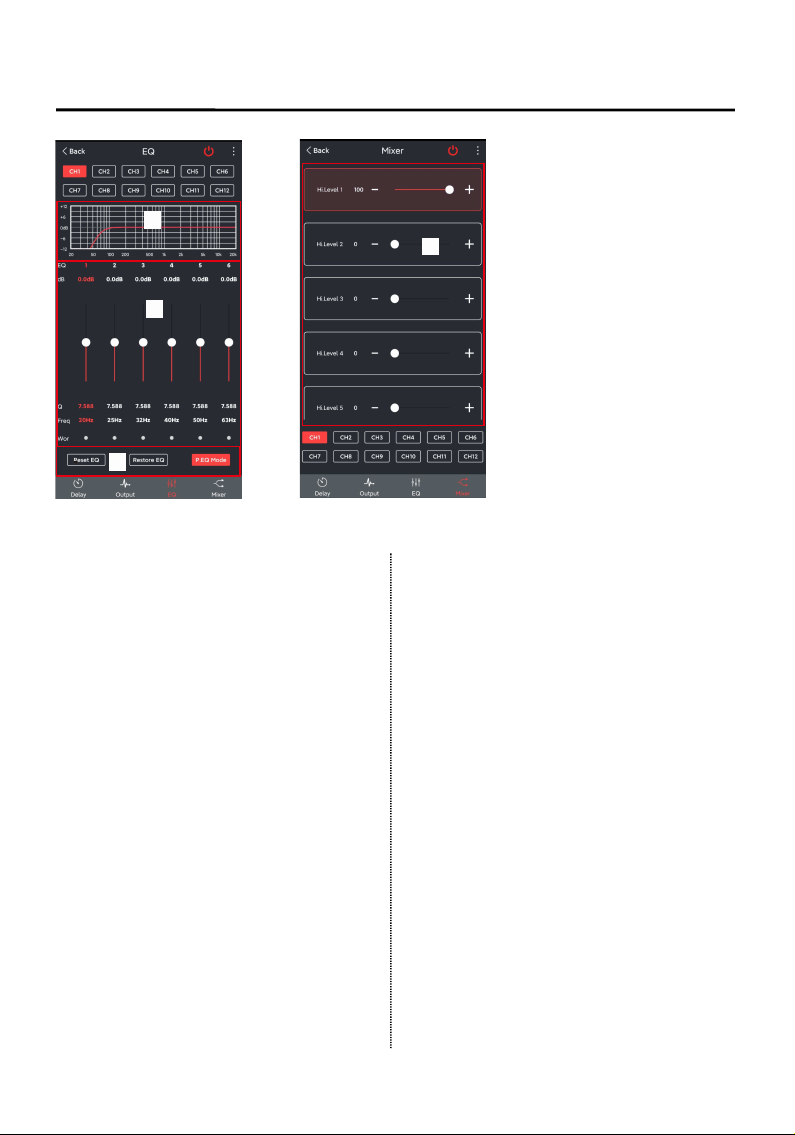
4. EQ interface
Corresponding to the adjustment of the
output channel EQ curve (gain, Q value
and frequency); reset equalization,
pass-through equalization or parametric
equalization operation settings.
M. EQ display:
Edit the display area.
N. Output EQ gain, Q value and frequency
settings:
Output EQ gain setting: A total of 31 EQ, left
and right sliding screen can select EQ, you
can drag the slider up and down. Select
the first line value, and drag the slider bar
left and right in the pop-up dialog box to
adjust the adjustment range: -12dB~+12dB.
Q value: Click the second line value, and
drag the slider bar left and right in the
pop-up dialog box to adjust, the
adjustment range is 0.404~28.852.
N
O
M
P
will pop up, and select the joint debugging
method.

SOFTWARE INTRODUCTION(SMARTPHONE)
O. Reset equalization, restore equalization,
pass-through equalization settings:
Click [Reset EQ] to restore the
parameters of the 31-band equalizer to
the original pass-through mode (the
equalizer frequency, Q value and gain
are restored to their initial values).
When there is channel adjustment,
display [straight-through equalization],
click [straight-through equalization], click
[OK], all values (frequency, Q value and
gain) will return to the initial value. At this
time, the [straight-through equalization]
button will become [recovery
equalization]. Press the button and click
[Resume Equilibrium], all values
(frequency, Q value and gain) will be
restored to the value before the
pass-through.
Click [P.EQ Mode], click [OK] to switch to
Graphic Equalization, click [G.EQ Mode],
click [OK] to switch to Parametric
Equalization.
5. Mixing interface
6 high level, 2 AUX, digital left and digital
right, Bluetooth left and blue right mixing
selection and adjustment can be
performed. The adjusting range is 0 ~100.
14 EN