
MULTI+ ULTRA SERIES
Change for life
GREE ELECTRIC APPLIANCES, INC. OF ZHUHAI
MULTIU18HP230V1DO
MULTIU24HP230V1DO
MULTIU36HP230V1DO
MULTIU42HP230V1DO
Service & Parts Manual

Service Manual
Table of Contents
Table of Contents
Part
Ⅰ
: Technical Information
.......................................................................1
1. Summary
......................................................................................................................1
2. Specications
..........................................................................................................2
2.1 Specication Sheet ........................................................................................................... 2
2.2 Cooling Capacity Tables ...................................................................................................6
3. Outline Dimension Diagram
......................................................................10
4. Refrigerant System Diagram
.................................................................... 11
5. Electrical Part
.........................................................................................................12
5.1 Wiring Diagram ............................................................................................................... 12
5.2 PCB Printed Diagram .....................................................................................................15
6. Function and Control
......................................................................................17
Part
Ⅱ
: Installation and Maintenance
.................................................19
7. Safety Precautions
............................................................................................19
8. Installation Manual
............................................................................................21
8.1 Preparation before Installation .......................................................................................22
8.2 Installation Instruction ..................................................................................................... 24
9. Troubleshooting
..................................................................................................29
9.1 Malfunction Indicator .....................................................................................................29
9.2 Malfunction Checking and Elimination ...........................................................................30
9.3 Maintenance Method for Normal Malfunction ................................................................. 36
10. Exploded View and Parts List
..............................................................38
11. Removal Procedure
.......................................................................................44
Appendix:
........................................................................................................................58
Appendix 1: Reference Sheet of Celsius and Fahrenheit ....................................................58
Appendix 2: Pipe Expanding Method ...................................................................................58
Appendix 3: List of Resistance for Temperature Sensor ......................................................60
1
Technical Information
Service Manual
1. Summary
Part
Ⅰ
: Technical Information
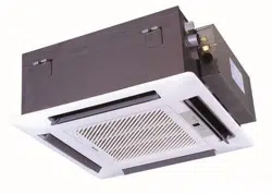
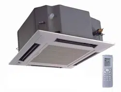
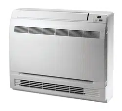
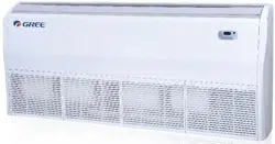
Outdoor Unit
No. Model Product Code
1 MULTIU18HP230V1DO CB228W09400
2 MULTIU24HP230V1DO CB228W09500
3 MULTIU36HP230V1DO CB228W09600
4 MULTIU42HP230V1DO CB228W09700
MULTIU18HP230V1DO
MULTIU24HP230V1DO
MULTIU36HP230V1DO
MULTIU42HP230V1DO
2
Technical Information
Service Manual
2. Specications
Model MULTIU18HP230V1DO MULTIU24HP230V1DO
Product Code CB228W09400 CB228W09500
Power
supply
Rated Voltage V~ 208/230 208/230
Rated Frequency Hz 60 60
Phases 1 1
Cooling capacity Btu/h 18000 22000
Heating capacity Btu/h 21000 26000
Cooling Power Input W 1450 1760
Heating Power Input W 1710 2090
Cooling Current Input A 6.3 7.65
Heating Current Input A 7.4 9.1
Rated Power Input W 5000 6000
Rated Current A 22 26
EER (Btu/h)/W 12.5 12.5
COP (Btu/h)/W 12.3 12.5
SEER 23 23
HSPF 10.5 10.5
Outdoor
Unit
Compressor Trademark
ZHUHAI LANDA COMPRESSOR
CO.,LTD
ZHUHAI LANDA COMPRESSOR
CO.LTD
Compressor Model QXFW-D318zX035 QXFW-D318zX035
Compressor Refrigerant Oil Type FW68DA or equivalent FW68DA or equivalent
Compressor Type Inverter Rotary Inverter Rotary
L.R.A A / /
Compressor Rated Load Amp (RLA) A 14.9 17
Compressor Power Input W / /
Compressor Thermal Protector / /
Throttling Method Electron expansion valve Electron expansion valve
Cooling Operation Ambient
Temperature Range
O
F 0~115 0~115
Heating Operation Ambient
Temperature Range
O
F -31~75.2 -31~75.2
Condenser Material Aluminum Fin-copper Tube Aluminum Fin-copper Tube
Condenser Pipe Diameter inch Φ5/16 Φ5/16
Rows-Fin Gap(mm) inch 2-1/16 2-1/16
Coil length (l) X height (H) X coil
width (L)
inch 38 21/32X29 7/16X1 1/2 38 21/32X29 7/16X1 1/2
Fan Motor Speed (rpm) (H/M/L) rpm 880 880
Output of Fan Motor W 90
90
Fan Motor RLA A / /
Fan Motor Capacitor μF / /
Air Flow Volume of Outdoor Unit CFM 2531 2531
Fan Type-Piece Axial-ow Axial-ow
Fan Diameter inch 21 43/64-2 39/64 Φ21 19/32-4 45/64
Defrosting Method Automatic Defrosting Automatic Defrosting
Climate Type T1 T1
Isolation I I
Moisture Protection IPX4 IPX4
Permissible Excessive Operating
Pressure for the Discharge Side
PSIG 550 550
Permissible Excessive Operating
Pressure for the Suction Side
PSIG 240 240
Dimension (WXHXD) inch 39 31/64X31 7/64X16 13/32 39 31/64X31 7/64X16 13/32
Dimension of Package (LXWXH) inch 42 1/2X19X33 42 1/2X19X33
Dimension of Package(LXWXH) inch 42 43/64X19 13/64X33 43/64 42 43/64X19 13/64X33 43/64
Net Weight lb 172 174.2
Gross Weight lb 183 185.2
Refrigerant Charge R410A R410A
Refrigerant Charge oz 77.62 95.26
2.1 Specication Sheet
3
Technical Information
Service Manual
Outdoor
Unit
Cross-sectional Area of Power Cable Conductor sq in 0.0051 0.0051
Recommended Power Cable(Core) N 3 3
Connection Pipe Connection Method - Flare Connection Flare Connection
Not Additional Gas Connection Pipe Length ft 65.6 98.4
Connection Pipe Gas Additional Charge oz/ft. 0.2 0.2
Outer Diameter of Liquid Pipe1(GREE Allocation)
(Metric)
inch 1/4 1/4
Outer Diameter of Liquid Pipe2(GREE Allocation)
(Metric)
inch 1/4 1/4
Outer Diameter of Liquid Pipe3(GREE Allocation)
(Metric)
inch / 1/4
Outer Diameter of Liquid Pipe4(GREE Allocation)
(Metric)
inch / /
Outer Diameter of Gas Pipe1(GREE Allocation)
(Metric)
inch 3/8 3/8
Outer Diameter of Gas Pipe2(GREE Allocation)
(Metric)
inch 3/8 3/8
Outer Diameter of Gas Pipe3(GREE Allocation)
(Metric)
inch / 3/8
Outer Diameter of Gas Pipe4(GREE Allocation)
(Metric)
inch / /
Connection Pipe Max. Height Distance(indoor and
indoor)
ft 26.2 26.2
Connection Pipe Max. Height Distance(indoor and
outdoor and indoor up)
ft
33 33
Connection Pipe Max. Height Distance(indoor and
outdoor and outdoor up)
ft
33 33
Max. equivalent connection pipe length(outdoor to
last indoor)
ft 82.0 82.0
Connection Pipe Max. Length Distance(total lenght) ft 164 229.6
The above data is subject to change without notice; please refer to the nameplate of the unit.

4
Technical Information
Service Manual
Model MULTIU36HP230V1DO MULTIU42HP230V1DO
Product Code CB228W09600 CB228W09700
Power
supply
Rated Voltage V~ 208/230 208/230
Rated Frequency Hz 60 60
Phases 1 1
Cooling capacity Btu/h 36000 42000
Heating capacity Btu/h 36000 42000
Cooling Power Input W 4020 4660
Heating Power Input W 3300 3600
Cooling Current Input A 17.48 20.26
Heating Current Input A 14.35 15.65
Rated Power Input W 7360 7360
Rated Current A 32 32
EER (Btu/h)/W 9.0 9.0
COP (Btu/h)/W 10.96 11.66
SEER 23.0 23.0
HSPF 10.0 10.0
Outdoor
Unit
Compressor Trademark
ZHUHAI LANDA COMPRESSOR
CO.,LTD
ZHUHAI LANDA COMPRESSOR
CO.,LTD
Compressor Model QXAW-F518zX440C QXAW-F518zX440C
Compressor Refrigerant Oil Type FW68DA or equivalent FW68DA or equivalent
Compressor Type Inverter Rotary Inverter Rotary
L.R.A A / /
Compressor Rated Load Amp (RLA) A 27 28.5
Compressor Power Input W / /
Compressor Thermal Protector / /
Throttling Method Electron expansion valve Electron expansion valve
Cooling Operation Ambient Temperature
Range
O
F 0~115 0~115
Heating Operation Ambient Temperature
Range
O
F -31~75.2 -31~75.2
Condenser Material Aluminum Fin-copper Tube Aluminum Fin-copper Tube
Condenser Pipe Diameter inch Φ5/16 Φ5/16
Rows-Fin Gap(mm) inch 3 3
Coil length (l) X height (H) X coil width (L) inch 35X41 37/64X2 1/4 35X41 37/64X2 1/4
Fan Motor Speed (rpm) (H/M/L) rpm 940 940
Output of Fan Motor W 90 90
Fan Motor RLA A / /
Fan Motor Capacitor μF / /
Air Flow Volume of Outdoor Unit CFM / /
Fan Type-Piece Axial-ow Axial-ow
Fan Diameter-height inch Φ22 7/16—5 63/64 Φ22 7/16—5 63/64
Defrosting Method Automatic Defrosting Automatic Defrosting
Climate Type T1 T1
Isolation I I
Moisture Protection IPX4 IPX4
Permissible Excessive Operating Pressure for
the Discharge Side
PSIG 550 550
Permissible Excessive Operating Pressure for
the Suction Side
PSIG 240 240
Dimension (W/H/D) inch 43 7/64X43 27/64X17 21/64 43 7/64X43 27/64X17 21/64
Dimension of Package (L/W/H) inch 46X18 57/64X43 57/64 46X18 57/64X43 57/64
Dimension of Package(L/W/H) inch 46 1/6X19X44 1/2 46 1/6X19X44 1/2
Net Weight lb 280 282.2
Gross Weight lb 297.7 299.9
Refrigerant Charge R410A R410A
Refrigerant Charge oz 158.73 176.37
5
Technical Information
Service Manual
Outdoor
Unit
Cross-sectional Area of Power Cable Conductor sq in 0.013 0.013
Recommended Power Cable(Core) N 3 3
Connection Pipe Connection Method - Flare Connection Flare Connection
Not Additional Gas Connection Pipe Length ft 131.2 131.2
Connection Pipe Gas Additional Charge oz/ft. 0.2 0.2
Outer Diameter of Liquid Pipe1(GREE Allocation)
(Metric)
inch 1/4 1/4
Outer Diameter of Liquid Pipe2(GREE Allocation)
(Metric)
inch 1/4 1/4
Outer Diameter of Liquid Pipe3(GREE Allocation)
(Metric)
inch 1/4 1/4
Outer Diameter of Liquid Pipe4(GREE Allocation)
(Metric)
inch 1/4 1/4
Outer Diameter of Liquid Pipe4(GREE Allocation)
(Metric)
inch / 1/4
Outer Diameter of Gas Pipe1(GREE Allocation)
(Metric)
inch 3/8 3/8
Outer Diameter of Gas Pipe2(GREE Allocation)
(Metric)
inch 3/8 3/8
Outer Diameter of Gas Pipe3(GREE Allocation)
(Metric)
inch 3/8 3/8
Outer Diameter of Gas Pipe4(GREE Allocation)
(Metric)
inch 3/8 3/8
Outer Diameter of Gas Pipe4(GREE Allocation)
(Metric)
inch / 3/8
Connection Pipe Max. Height Distance(indoor and
indoor)
ft 49.2 49.2
Connection Pipe Max. Height Distance(indoor and
outdoor and indoor up)
ft 49.2 49.2
Connection Pipe Max. Height Distance(indoor and
outdoor and outdoor up)
ft 49.2 49.2
Max. equivalent connection pipe length(outdoor to
last indoor)
ft 82.0 82.0
Connection Pipe Max. Length Distance(total lenght) ft 246.1 262.5
The above data is subject to change without notice; please refer to the nameplate of the unit.
6
Technical Information
Service Manual
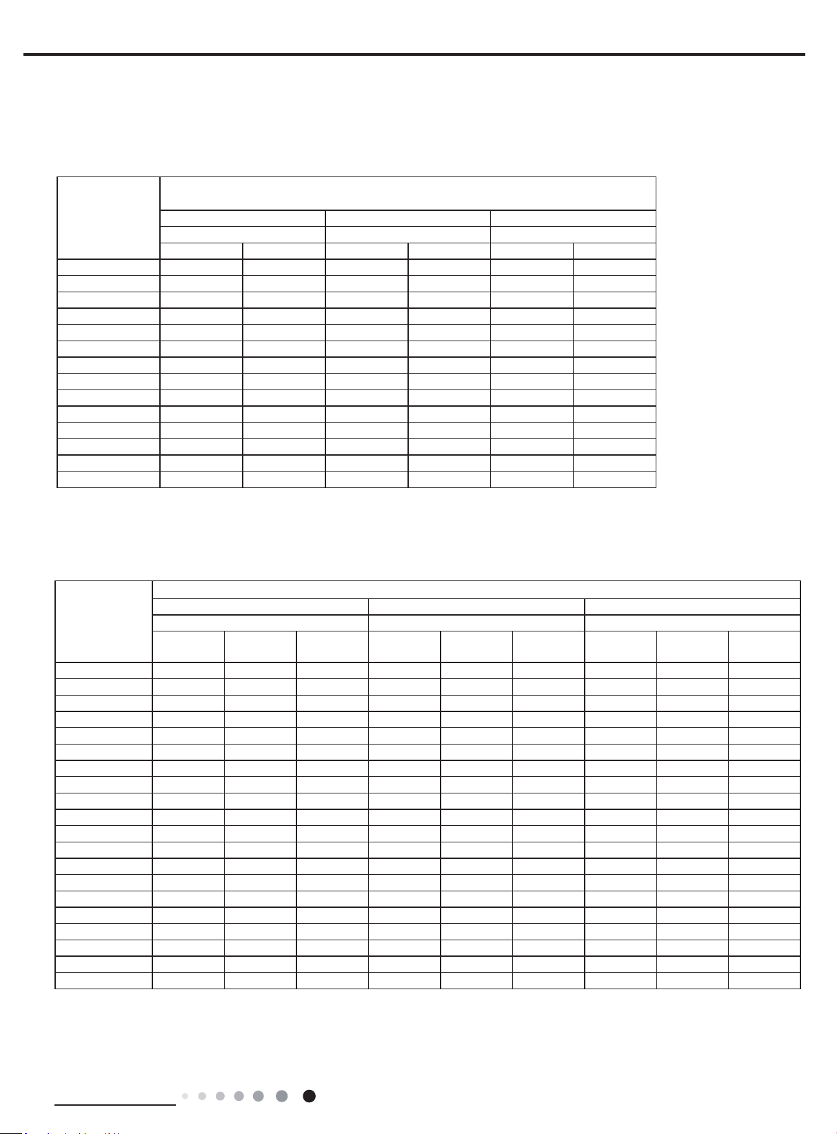
Cooling
Heatling
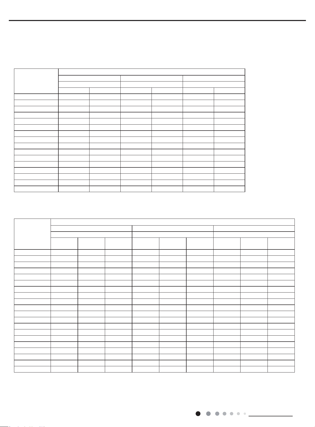
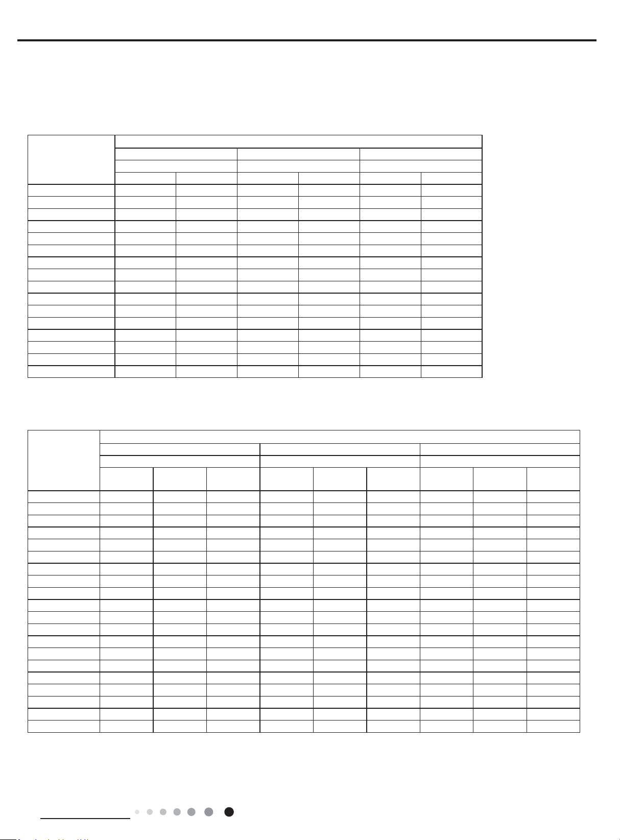
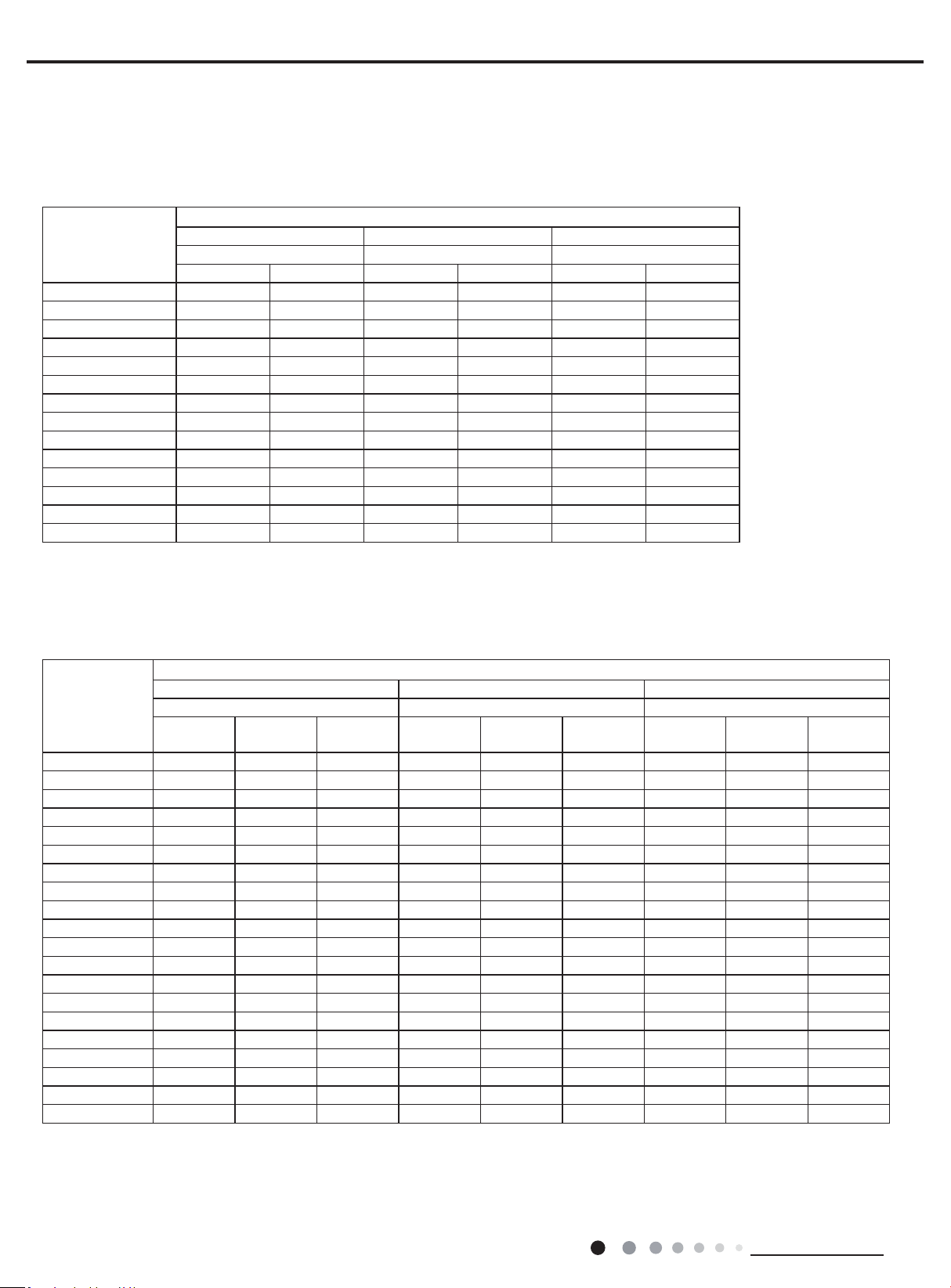
2.2 Cooling Capacity Tables
MULTIU18HP230V1DO
Outdoor Ambient
Temperature (DB)
°F
Indoor Entering Air Temperatures
68F DB 73°F DB 80°F DB
57F WB 61°FWB 67°FWB
TC SHC TC SHC TC SHC
0°F 11182 8769 11822 9262 13018 10214
5°F 11573 9076 12235 9586 13473 10571
14°F 12122 9507 12806 10040 14453 11336
23°F 13281 10418 14206 11143 16277 12766
32°F 14113 11069 14909 11693 16826 13193
41°F 14620 11467 15440 12109 17644 13835
50°F 14875 11666 15910 12478 18230 14294
59°F 16106 12631 17227 13510 18867 14793
68°F 18240 14306 19380 15197 20710 16243
77°F 18025 14139 19171 15037 20520 16096
86°F 17138 13440 18278 14338 19950 15647
95°F 16220 12721 17353 13607 19000 14902
104°F 15434 12105 16562 12991 18506 14517
113°F 15035 11791 16169 12676 18113 14203
122°F 14643 11483 15770 12368 17721 13895
129°F 14250 11175 15200 11919 17100 13414
Outdoor Ambient
Temperature
(DB) °F
Indoor Entering Air Temperatures
68F DB 73°F DB 80°F DB
57F WB 61°FWB 67°FWB
TC
Power Input
(KW)
COP TC
Power Input
(KW)
COP TC
Power Input
(KW)
COP
-31°F 16500 4.80 1.01 16300 4.65 1.03 15900 4.63 1.01
-22°F 18902 4.89 1.13 18401 4.94 1.09 18030 4.95 1.07
-13°F 20698 4.96 1.22 20160 5.01 1.18 19762 5.02 1.15
-5°F 22479 3.28 2.01 21906 3.32 1.93 21482 3.43 1.84
0°F 22148 3.34 1.94 21565 3.38 1.87 21130 3.49 1.78
5°F 22251 3.17 2.06 21672 3.21 1.98 21245 3.31 1.88
10°F 22498 3.20 2.06 21913 3.24 1.98 21475 3.34 1.88
17°F 22072 3.18 2.03 21492 3.22 1.96 21053 3.32 1.86
19°F 21778 2.97 2.15 21478 3.01 2.09 21036 3.10 1.99
24°F 21108 3.08 2.01 20856 3.11 1.96 20478 3.21 1.87
32°F 20566 2.95 2.05 20339 2.98 2.00 20008 3.07 1.91
41°F 21375
2.73 2.30 21165 2.76 2.25 20848 2.84 2.15
43°F 21960 2.13 3.02 21750 2.16 2.96 21440 2.22 2.82
47°F 24000 2.18 3.23 23340 2.20 3.10 22846 2.27 2.94
53°F 24240 1.98 3.59 23573 2.00 3.45 23079 2.07 3.27
59°F 22316 2.00 3.27 21695 2.02 3.14 21236 2.09 2.98
64°F 22788 1.83 3.64 22160 1.85 3.50 21695 1.91 3.32
70°F 23220 1.86 3.66 22579 1.88 3.51 22100 1.94 3.33
75°F 23544 1.70 4.06 22896 1.72 3.90 22417 1.78 3.70
78°F 23760 1.72 4.06 23105 1.74 3.90 22619 1.79 3.70
7
Technical Information
Service Manual
Cooling
Heatling
MULTIU24HP230V1DO
Outdoor Ambient
Temperature (DB)
°F
Indoor Entering Air Temperatures
68F DB 73°F DB 80°F DB
57F WB 61°FWB 67°FWB
TC SHC TC SHC TC SHC
0°F 17067 13385 18044 14137 19870 15590
5°F 17664 13852 18674 14631 20564 16135
14°F 18502 14511 19546 15324 22059 17302
23°F 20271 15901 21682 17008 24843 19485
32°F 21541 16894 22756 17847 25682 20137
41°F 22315 17502 23566 18482 26931 21116
50°F 22704 17806 24284 19045 27825 21817
59°F 24582 19279 26293 20621 28797 22579
68°F 27840 21835 29580 23196 31610 24792
77°F 27511 21580 29261 22951 31320 24567
86°F 26158 20513 27898 21884 30450 23882
95°F 24756 19417 26487 20768 29000 22746
104°F 23558 18477 25278 19828 28246 22158
113°F 22949 17997 24679 19348 27647 21678
122°F 22349 17527 24070 18878 27047 21208
129°F 21750 17057 23200 18193 26100 20474
Outdoor Ambient
Temperature
(DB) °F
Indoor Entering Air Temperatures
68F DB 73°F DB 80°F DB
57F WB 61°FWB 67°FWB
TC
Power Input
(KW)
COP TC
Power Input
(KW)
COP TC
Power Input
(KW)
COP
-31°F 21500 5.45 1.16 21000 5.50 1.12 20500 5.70 1.05
-22°F 24954 5.50 1.33 24292 5.57 1.28 23801 5.74 1.21
-13°F 27324 5.58 1.44 26614 5.64 1.38 26089 5.82 1.31
-5°F 31846 5.42 1.72 31034 5.48 1.66 30433 5.66 1.58
0°F 31376 5.51 1.67 30550 5.58 1.61 29933 5.75 1.52
5°F 31523 5.24 1.76 30703 5.30 1.70 30097 5.46 1.61
10°F 31872 5.29 1.77 31044 5.35 1.70 30423 5.52 1.62
17°F 31268 5.25 1.75 30448 5.31 1.68 29825 5.48 1.60
19°F 30852 4.91 1.84 30427 4.96 1.80 29802 5.12 1.71
24°F 29903 5.08 1.72 29546 5.14 1.68 29011 5.30 1.60
32°F 29135 4.86 1.76 28814 4.92 1.72 28344 5.07 1.64
41°F 30281
4.50 1.97 29984 4.55 1.93 29535 4.69 1.84
43°F 31110 3.52 2.59 30813 3.56 2.54 30373 3.67 2.42
47°F 34000 3.60 2.77 33065 3.64 2.66 32366 3.76 2.52
53°F 34340 3.27 3.08 33394 3.31 2.96 32695 3.41 2.81
59°F 31614 3.30 2.81 30734 3.34 2.70 30085 3.45 2.56
64°F 32283 3.03 3.12 31394 3.06 3.00 30734 3.16 2.85
70°F 32895 3.08 3.13 31987 3.11 3.01 31308 3.21 2.86
75°F 33354 2.81 3.48 32436 2.84 3.34 31757 2.93 3.17
78°F 33660 2.84 3.48 32732 2.87 3.34 32044 2.96 3.17
8
Technical Information
Service Manual
Cooling
Heatling
MULTIU36HP230V1DO
Outdoor Ambient
Temperature (DB)
°F
Indoor Entering Air Temperatures
68F DB 73°F DB 80°F DB
57F WB 61°FWB 67°FWB
TC SHC TC SHC TC SHC
0°F 21827 16500 22800 18000 24000 19500
5°F 21927 17196 23181 18162 25527 20029
14°F 22968 18014 24264 19023 27384 21478
23°F 25164 19740 26916 21113 30840 24188
32°F 25758 45964 27663 49363 31994 57088
41°F 23613 65750 25520 71058 29746 82822
50°F 21549 81552 23437 88695 27533 104195
59°F 30516 23933 32640 25598 35748 28029
68°F 34560 27106 36720 28795 39240 30776
77°F 34152 26790 36324 28491 38880 30497
86°F 32472 25465 34632 27166 37800 29646
95°F 30732 24103 32880 25781 36000 28236
104°F 29244 22936 31380 24614 35064 27507
113°F 27744 21757 29880 23435 33576 26328
Outdoor Ambient
Temperature
(DB) °F
Indoor Entering Air Temperatures
68F DB 73°F DB 80°F DB
57F WB 61°FWB 67°FWB
TC
Power Input
(KW)
COP TC
Power Input
(KW)
COP TC
Power Input
(KW)
COP
-31°F 23000 5.50 1.23 24000 5.72 1.23 24500 5.85 1.23
-22°F 25563 5.57 1.34 25910 5.73 1.33 24899 5.91 1.24
-13°F 28859 5.65 1.50 28373 5.81 1.43 27293 5.99 1.33
-5°F 33638 5.64 1.75 33072 5.79 1.67 31837 5.98 1.56
0°F 36089 5.73 1.85 35488 5.89 1.77 34105 6.08 1.64
5°F 36259 5.70 1.86 35648 5.86 1.78 34291 6.05 1.66
10°F 39753 5.76 2.02 39091 5.92 1.94 37581 6.11 1.80
17°F 41794 5.72 2.14 41097 5.88 2.05 39475 6.06 1.91
19°F 41758 5.50 2.23 41075 5.65 2.13 39443 5.83 1.98
24°F 40398 5.42 2.18 39787 5.58 2.09 38397 5.75 1.96
32°F 39260 5.19 2.22 38728 5.33 2.13 37514 5.50 2.00
41°F 40725
5.11 2.33 40247 5.26 2.24 39090 5.42 2.11
43°F 41822 5.10 2.40 41330 5.24 2.31 40199 5.41 2.18
47°F 45450 5.22 2.55 44663 5.36 2.44 42837 5.53 2.27
53°F 45900 4.74 2.84 45098 4.87 2.71 43272 5.03 2.52
59°F 42259 4.78 2.59 41513 4.92 2.47 39818 5.07 2.30
64°F 43158 4.39 2.88 42398 4.51 2.75 40678 4.65 2.56
70°F 43968 4.46 2.89 43208 4.58 2.76 41437 4.73 2.57
75°F 44588 4.07 3.21 43803 4.19 3.07 42031 4.32 2.85
78°F 44993 4.11 3.21 44208 4.22 3.07 42411 4.36 2.85
9
Technical Information
Service Manual
Outdoor Ambient
Temperature (DB)
°F
Indoor Entering Air Temperatures
68F DB 73°F DB 80°F DB
57F WB 61°FWB 67°FWB
TC SHC TC SHC TC SHC
0°F 24000 19500 26000 20500 28900 22300
5°F 25582 20062 27045 21189 29782 23368
14°F 26796 21016 28308 22193 31948 25057
23°F 29358 23030 31402 24632 35980 28220
32°F 30051 53625 32274 57590 37327 66603
41°F 27549 76709 29773 82901 34704 96626
50°F 25141 95143 27343 103477 32122 121561
59°F 35602 27922 38080 29865 41706 32701
68°F 40320 31623 42840 33594 45780 35906
77°F 39844 31254 42378 33240 45360 35580
86°F 37884 29709 40404 31694 44100 34587
95°F 35854 28121 38360 30078 42000 32942
104°F 34118 26759 36610 28716 40908 32091
113°F 32368 25384 34860 27341 39172 30716
MULTIU42HP230V1DO Cooling
Heatling
Outdoor Ambient
Temperature
(DB) °F
Indoor Entering Air Temperatures
68F DB 73°F DB 80°F DB
57F WB 61°FWB 67°FWB
TC
Power Input
(KW)
COP TC
Power Input
(KW)
COP TC
Power Input
(KW)
COP
-31°F 27000 5.50 1.44 28000 5.70 1.44 26000 5.85 1.30
-22°F 28744 5.57 1.51 29134 5.73 1.49 27998 5.91 1.39
-13°F 32450 5.65 1.68 31904 5.81 1.61 30689 5.99 1.50
-5°F 37824 5.64 1.97 37188 5.79 1.88 35799 5.98 1.76
0°F 40580 5.73 2.08 39905 5.89 1.99 38349 6.08 1.85
5°F 40771 5.70 2.10 40085 5.86 2.00 38558 6.05 1.87
10°F 44700 5.76 2.27 43955 5.92 2.18 42258 6.11 2.03
17°F 42723 5.72 2.19 42011 5.88 2.10 40352 6.06 1.95
19°F 42686 5.50 2.28 41988 5.65 2.18 40320 5.83 2.03
24°F 41296 5.42 2.23 40671 5.58 2.14 39250 5.75 2.00
32°F 40132 5.19 2.27 39589 5.33 2.18 38348 5.50 2.04
41°F 41630
5.11 2.39 41141 5.26 2.29 39959 5.42 2.16
43°F 42751 5.10 2.46 42248 5.24 2.36 41093 5.41 2.23
47°F 46460 5.22 2.61 45655 5.36 2.50 43789 5.53 2.32
53°F 46920 4.74 2.90 46101 4.87 2.77 44234 5.03 2.58
59°F 43198 4.78 2.65 42435 4.92 2.53 40703 5.07 2.35
64°F 44117 4.39 2.95 43341 4.51 2.82 41582 4.65 2.62
70°F 44945 4.46 2.96 44169 4.58 2.83 42358 4.73 2.63
75°F 45579 4.07 3.28 44777 4.19 3.14 42965 4.32 2.92
78°F 45993 4.11 3.28 45191 4.22 3.14 43353 4.36 2.92
10
Technical Information
Service Manual
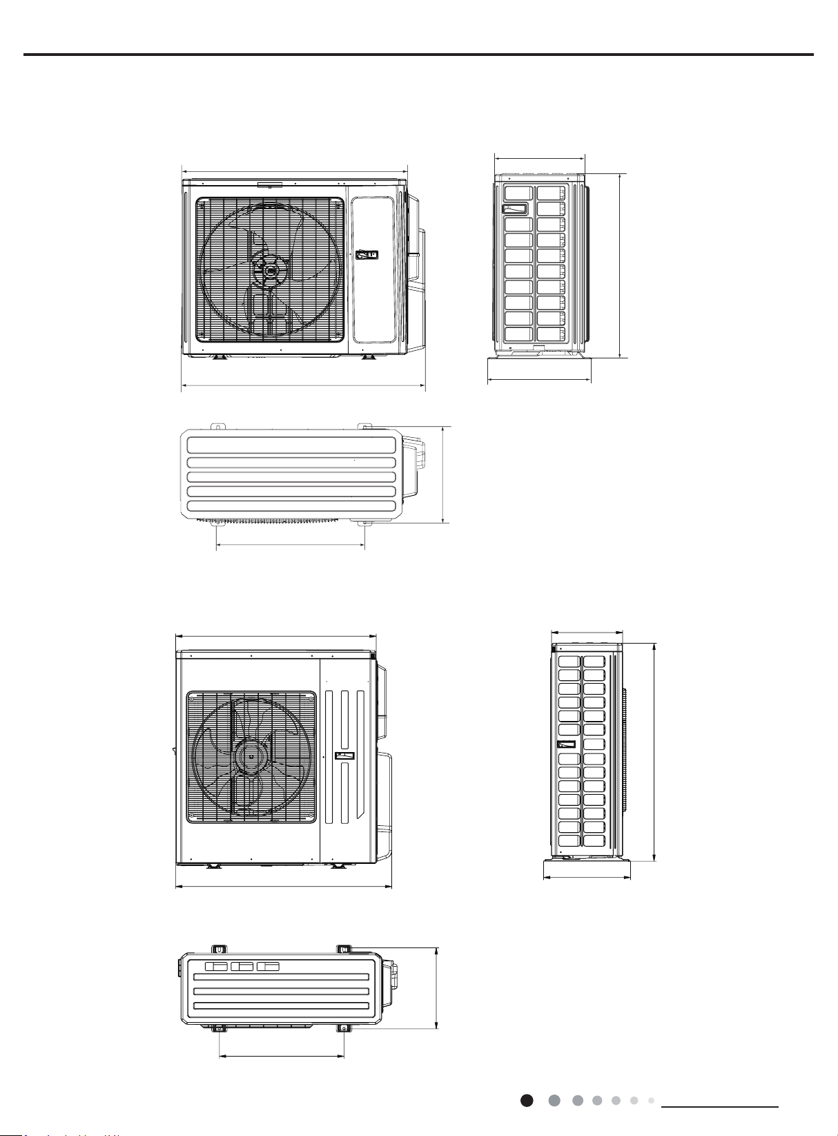
MULTIU36HP230V1DO MULTIU42HP230V1DO
Unit:inch
40
43 7/64
24 13/16
14 1/4
17 21/64
43 27/64
14 51/64
Unit:inc
h
39 31/64
36 7/32
16 13/32
14 37/64
31 7/64
24
15 23/32
3. Outline Dimension Diagram
MULTIU18HP230V1DO MULTIU24HP230V1DO
11
Technical Information
Service Manual
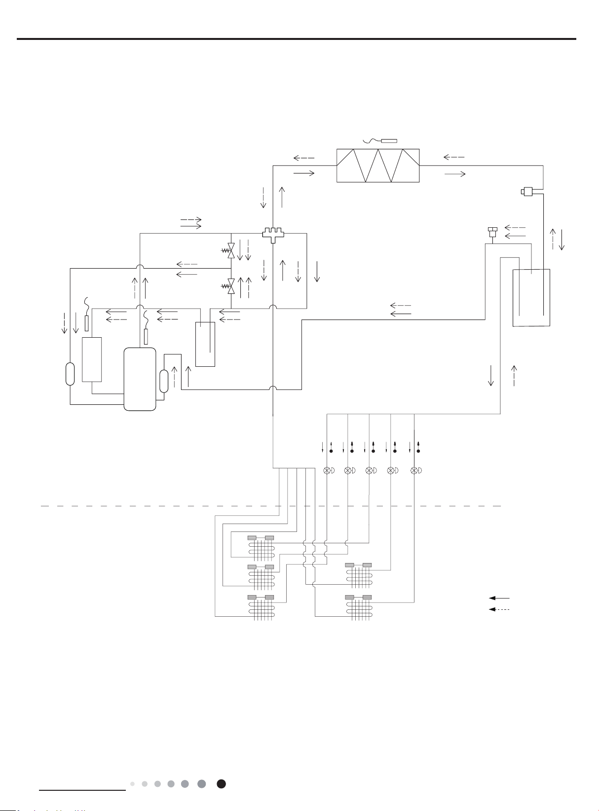
4. Refrigerant System Diagram
Schematic Diagram of Free Match Series Inverter Heat Pump System:
Electronic
expansion
valve A
Flash vaporizer
Unloading valve
Outdoor evaporator
4-way valve
Solenoid valve
(high pressure)
Solenoid valve
(low pressure)
Air injection
Compressor
Variable
volume
Gas-liquid
separator
Gas-liquid
separator
COOLING
HEATING
Heat Exchanger
Heat Exchanger
Heat Exchanger
Heat Exchanger
Heat Exchanger
Indoor Uint
Electronic Expansion Valve
Outdoor Uin
12
Technical Information
Service Manual
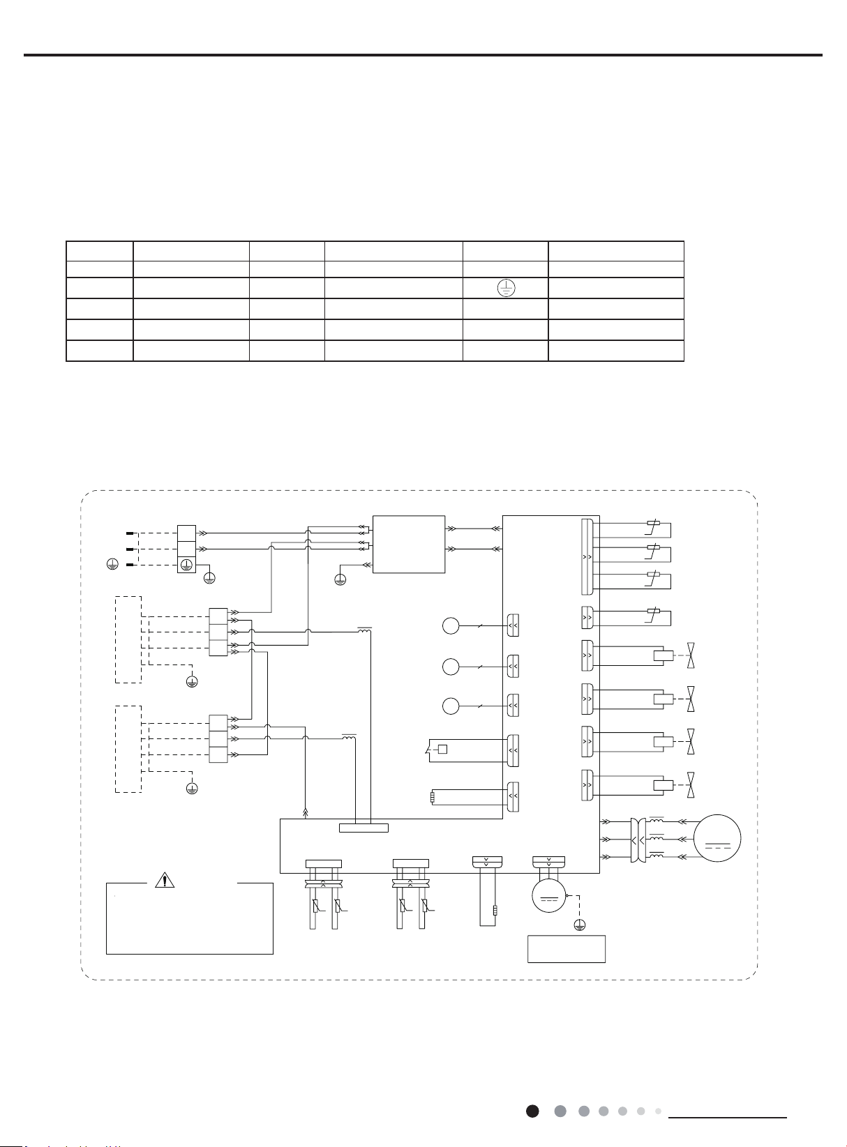
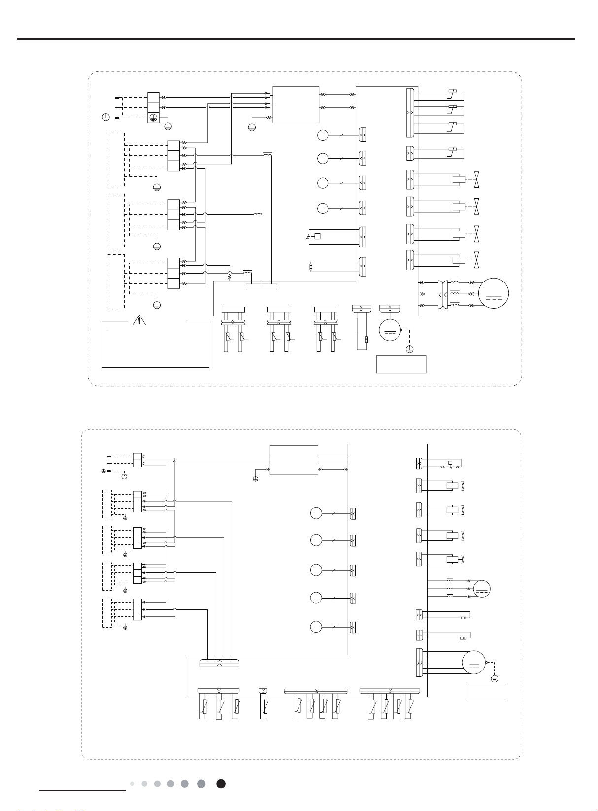
5. Electrical Part
5.1 Wiring Diagram
Symbol Symbol Color Symbol Symbol Color Symbol Name
WH White GN GREEN COMP Compressor
YE Yellow BN Brown Grouding wire
RD Red BU Blue
YEGN Yellow/Green BK Black
VT Violet OG Orange
● Outdoor Unit
●Instruction
MULTIU18HP230V1DO
60000706049101
0
*
2)$1
<(*1
*
02725
/
/
/
/
*
32:(5
7(036(1625
7(036(1625
7(036(1625
(;+$867
2875220
28778%(
&203
6(16256(1625
7(03
%.
5'
<(
%8
5'
<(
%8
%.
%.5'5'%.
:+
*<
%.
%1%8
7(50,1$/
7(50,1$/%/2&.
1
;7%
1
;7$
/
/
;7
4$
<%4%
<$
78%(%
57
57
57
57
78%($
&20,11(5
$&1
57
57
;
:5'
:
9
/
8%8
9<(
8
57
76(1625
%8
)$
)%
(.9
(.9
(/(&7521,&
(;3$16,21
9$/9($
*
*
%/2&.
%/2&.
7(50,1$/
9$/9(%
(;3$16,21
(/(&7521,&
;;
<(*1
)$1
*$6
3,3(
7(03
3,3(
/,48,'
/,48,'
3,3(
7(03
3,3(
*$6
7(03
6(16256(1625
+($7%
5'5'
$&1
$&/
1
(3(
1
$&/
$3
$&/
*
<(*1
%1
%8
%1
%8
%8%1
0DLQ%RDUG
/
/
:+%8
%.
5'%1
*1<(*1
:+%8
%.
5'%1
*1<(*1
5'
+($7&
5'
%$1'+($7(5
&2035(6625
(+
35(6685(
6:,7&+
+,*+
:+
:+
+33
3
<9
%8
%8
<9
%8
%8
<9
%8
%8
:$<
<9
9$/9(
:$<
97
97
(+
+($7(5
%$1'
%27720
)
(.9
(/(&7521,&
(;3$16,21
9$/9(
7(036(1625
68&7,21
%.
57
6(1625
.
:+ .
.
.
0$*1(7,&
5,1*
0$*1(7,&
5,1*
0$*1(7,&
5,1*
:+%8
%.%1
*1<(*1
:$51,1*
$30$,1%2$5'
3OHDVHGRQWWRXFKDQ\WHUPLQDO
ZKHQWKHYROWDJHRIWHUPLQDO
3'&DQG1'&DW$3LV
KLJKHUWKDQ9WRSUHYHQWWKH
ULVNRIHOHFWULFDOVKRFN
,1'22581,7$,1'22581,7%
LURQVKHOOPRWRU
RQO\DSSOLHVWRWKH
127(0RWRUJURXQG
:$<
9$/9(
0$.(83
&1
EOXH
&1
UHG
&1
JUHHQ
35(6685(
:$<9$/9(
/2:
35(6685(
:$<9$/9(
+,*+
EODFN
ZKLWH
JUHHQ
&203
+36
13
Technical Information
Service Manual
MULTIU24HP230V1DO
600007060491
0
*
2)$1
<(*1
*
02725
/
/
/
/
*
32:(5
7(036(1625
7(036(1625
7(036(1625
(;+$867
2875220
28778%(
&203
6(16256(1625
7(03
%.
5'
<(
%8
5'
<(
%8
5'%.
5'
%.
%.5'5'%.
:+
:+
*<
%.
%1
%8
%1
%8
7(50,1$/
7(50,1$/%/2&.
1
1
;7%
1
;7$
/
/
;7
4$
<&4&<%4%
<$
57
57
78%(&78%(%
57
57
57
57
78%($
&20,11(5
$&1
57
57
;
:5'
:
9
/
8%8
9<(
8
57
76(1625
;7&
%8
)$
)%
)&
(.9
(.9
(.9
(/(&7521,&
(;3$16,21
9$/9($
*
*
*
%/2&.
%/2&.
7(50,1$/
%/2&.
7(50,1$/
9$/9(%
(;3$16,21
(/(&7521,&
(/(&7521,&
(;3$16,21
9$/9(&
;;
;
<(*1
)$1
*$6
3,3(
7(03
3,3(
/,48,'
/,48,'
3,3(
7(03
3,3(
*$6
7(03
6(16256(16256(16256(1625
7(03
*$6
3,3(
7(03
3,3(
/,48,'
+($7%
5'5'
$&1
$&/
1
(3(
1
$&/
$3
$&/
*
<(*1
%1
%8
%1
%8
%8%1
0DLQ%RDUG
/
/
/
:+%8
%.
5'%1
*1<(*1
:+%8
%.
5'%1
*1<(*1
:+%8
%.
5'%1
*1<(*1
5'
+($7&
5'
%$1'+($7(5
&2035(6625
(+
35(6685(
6:,7&+
+,*+
:+
:+
+33
3
<9
%8
%8
<9
%8
%8
<9
%8
%8
:$<
<9
9$/9(
:$<
97
97
(+
+($7(5
%$1'
%27720
)
(.9
(/(&7521,&
(;3$16,21
9$/9(
7(036(1625
68&7,21
%.
57
6(1625
.
:+ .
.
.
0$*1(7,&
5,1*
0$*1(7,&
5,1*
0$*1(7,&
5,1*
0$*1(7,&
5,1*
:+%8
%.%1
*1<(*1
:$51,1*
$30$,1%2$5'
3OHDVHGRQWWRXFKDQ\WHUPLQDO
ZKHQWKHYROWDJHRIWHUPLQDO
3'&DQG1'&DW$3LV
KLJKHUWKDQ9WRSUHYHQWWKH
ULVNRIHOHFWULFDOVKRFN
,1'22581,7$,1'22581,7%,1'22581,7&
LURQVKHOOPRWRU
RQO\DSSOLHVWRWKH
127(0RWRUJURXQG
:$<
9$/9(
0$.(83
&1
EOXH
&1
UHG
&1
JUHHQ
35(6685(
:$<9$/9(
/2:
35(6685(
:$<9$/9(
+,*+
EODFN
ZKLWH
UHG
JUHHQ
&203
+36
60000706063001
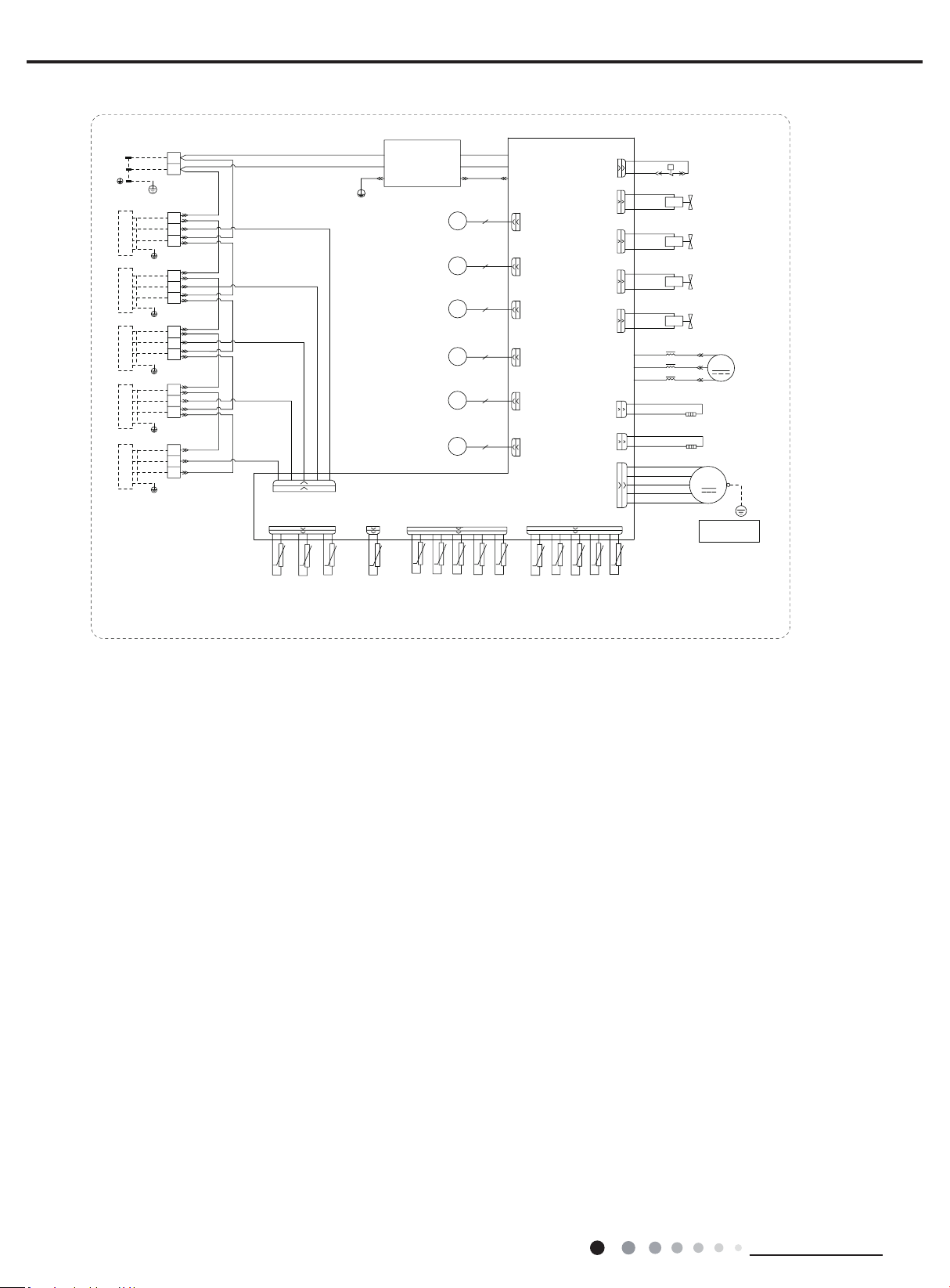
MULTIU36HP230V1DO
$&1
(3(
$&1
$&/
$3
$&/
%1
0DLQ%RDUG
%8
*
<(*1
$&1
%8
θ
.
θ
.
θ
.
θ
θ
.
θ
.
θ
.
θ
θ
.
θ
θ
/
/
%.%1
:+%8
*1<(*1
7(50,1$/
%/2&.
,1'22581,7$
1
*1<(*1
5'%1
:+%8
%.
*
;7$
1
1
,1'22581,7&
*1<(*1
5'%1
%.
:+%8
%.
5'%1
*1<(*1
;7%
*
*
;7&
*
%.
5'%1
*1<(*1
,1'22581,7'
:+%8
;7'
1
,1'22581,7%
:+%8
/
/
LURQVKHOOPRWRU
RQO\DSSOLHVWRWKH
1RWH0RWRUJURXQG
(+
θ
(+
+33
1
$&/
76(1625
$30DLQ%RDUG
0
2)$1
:$<
)'
)&
)%
)$
&20,11(5
)
&1
&1
&1
6(1625
EOXH
UHG
JUHHQ
1
\HOORZ
UHG
EODFN
ZKLWH
UHG
32:(5
.
&1
5757$
57%
57&
57'
&1
.
57$
57%57&
57'
.
5757
.
*
;7
%8%1
%8
%8
+36
3
%1
%1
%8
%1
7(50,1$/%/2&.
7(50,1$/%/2&.
7(50,1$/%/2&.
28778%(
7(50,1$/%/2&.
7(03
6(1625
2875220
7(03
6(1625
(;+$867
7(03
6(1625
/,48,'3,3(
7(03
6(1625
3(
3(
*$63,3(
7(03
6(1625
%8%1
:+
<(
%.
5'
(.9
.
68&7,21
7(03
6(1625
57
(.9
(.9
(.9
(.9
6:,7&+
+,*+35(6685(
/
/
&203
5'
<(
%8
:
9
/
8
&203
:5'
8%8
9<(
)$102725
<(*1
<9
:$<9$/9(
97
97
&2035(6625
5'
5'
+($7&
%$1'+($7(5
(/(&7521,&
(;3$16,21
9$/9($
(/(&7521,&
(;3$16,21
9$/9(%
(/(&7521,&
(;3$16,21
9$/9(&
(/(&7521,&
(;3$16,21
9$/9('
(/(&7521,&
(;3$16,21
9$/9(
<9
+,*+35(6685(
%8
%8
<9
/2:35(6685(
%8
%8
<9
0$.(83:$<
%8
%8
%27720
5'
5'
+($7%
%$1'+($7(5
:$<9$/9(
:$<9$/9(
9$/9(
:+
:+
0$*1(7,&
5,1*
14
Technical Information
Service Manual
600007060630
MULTIU42HP230V1DO
$&1
(3(
$&1
$&/
$3
$&/
%1
0DLQ%RDUG
%8
*
<(*1
$&1
%8
θ
.
θ
.
θ
.
θ
θ
.
θ
.
θ
.
θ
θ
.
θ
θ
/
/
%.%1
:+%8
*1<(*1
7(50,1$/
%/2&.
,1'22581,7$
1
*1<(*1
5'%1
:+%8
%.
*
;7$
1
1
,1'22581,7&
*1<(*1
5'%1
%.
:+%8
%.
5'%1
*1<(*1
;7%
*
*
;7&
*
%.
5'%1
*1<(*1
,1'22581,7'
:+%8
;7'
1
,1'22581,7%
:+%8
/
/
LURQVKHOOPRWRU
RQO\DSSOLHVWRWKH
1RWH0RWRUJURXQG
*
%.
5'%1
*1<(*1
,1'22581,7(
:+%8
;7(
1
θ
θ
(+
θ
(+
+33
1
$&/
76(1625
$30DLQ%RDUG
0
2)$1
:$<
)'
)&
)%
)$
)(
&20,11(5
)
&1
&1
&1
6(1625
EOXH
UHG
JUHHQ
1
JUHHQ
\HOORZ
UHG
EODFN
ZKLWH
UHG
32:(5
.
&1
5757$
57%
57&
57'
&1
.
57$
57%57&
57'
.
5757
.
*
;7
%8%1
%8
%8
+36
3
%1
%1
%8
%1
7(50,1$/%/2&.
7(50,1$/%/2&.
7(50,1$/%/2&.
28778%(
7(50,1$/%/2&.
7(03
6(1625
2875220
7(03
6(1625
(;+$867
7(03
6(1625
/,48,'3,3(
7(03
6(1625
3(
*$63,3(
7(03
6(1625
3(
7(50,1$/%/2&.
57(
.
57(
.
%8%1
%8%1
:+
<(
%.
5'
2*
(.9
.
68&7,21
7(03
6(1625
57
(.9
(.9
(.9
(.9
(.9
6:,7&+
+,*+35(6685(
/
/
&203
5'
<(
%8
:
9
/
8
&203
:5'
8%8
9<(
)$102725
<(*1
<9
:$<9$/9(
97
97
&2035(6625
5'
5'
+($7&
%$1'+($7(5
(/(&7521,&
(;3$16,21
9$/9($
(/(&7521,&
(;3$16,21
9$/9(%
(/(&7521,&
(;3$16,21
9$/9(&
(/(&7521,&
(;3$16,21
9$/9('
(/(&7521,&
(;3$16,21
9$/9((
(/(&7521,&
(;3$16,21
9$/9(
<9
+,*+35(6685(
%8
%8
<9
/2:35(6685(
%8
%8
<9
0$.(83:$<
%8
%8
%27720
5'
5'
+($7%
%$1'+($7(5
:$<9$/9(
:$<9$/9(
9$/9(
:+
:+
0$*1(7,&
5,1*
These circuit diagrams are subject to change without notice, please refer to the one supplied with the unit.
15
Technical Information
Service Manual
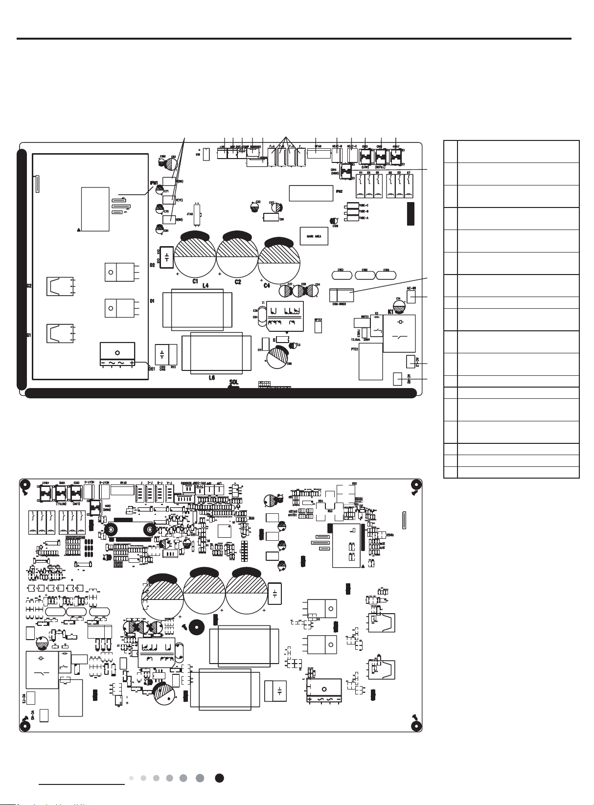
● TOP VIEW
● BOTTOM VIEW
1
Compressor three phase input
interface
2
Terminal of system low
pressure protection
3
Terminal of system high
pressure protection
4
Overload interface of
compressor
5
Interface of Inhalation
temperature package
6
Interface of temperature
sensor
7
Terminal of electronic
expansion valve
8 Interface of fan
9
Interface of electric heating for
chassis
10
Interface of electric heating for
compressor
11
Terminal of low pressure
2-way valve
12 Terminal of 2-way valve
13 Terminal of 4-way valve
14
Terminal of high pressure
2-way valve
15
Terminal of communication
wire
16 Terminal of neutral wire
17 Terminal of live wire
18 Terminal of neutral wire
5.2 PCB Printed Diagram
MULTIU18HP230V1DO
MULTIU24HP230V1DO
1234 56 78910111213
14
15
16
18
17
16
Technical Information
Service Manual
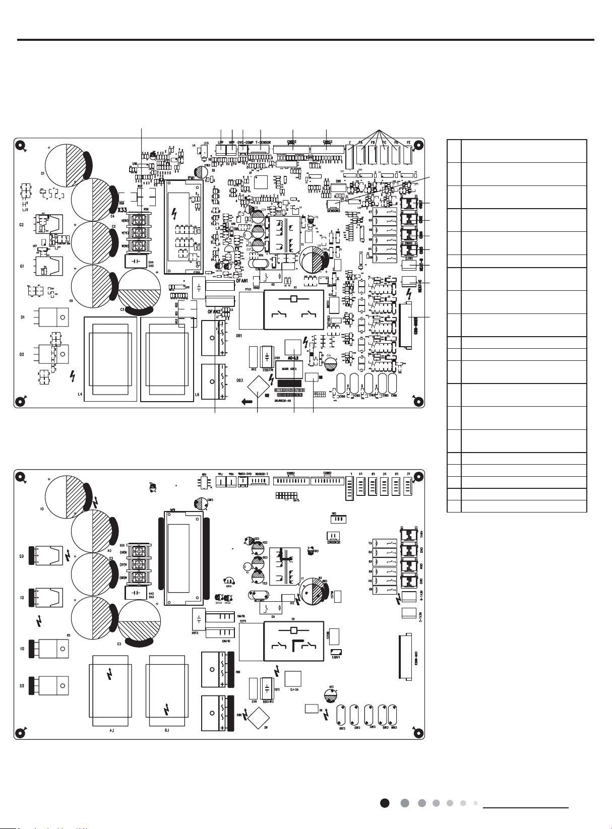
● TOP VIEW
● BOTTOM VIEW
1
Compressor three phase input
interface
2
Terminal of system low
pressure protection
3
Terminal of system high
pressure protection
4
Overload interface of
compressor
5
Interface of temperature
sensor
6
Air valve temperature package
7
Liquid valve temperature
package
8
Terminal of electronic
expansion valve
9
Inhalation temperature
package
10 Terminal of 4-way valve
11 Terminal of 2-way valve
12
Terminal of low pressure
2-way valve
13
Terminal of high pressure
2-way valve
14
Terminal of electric heating for
chassis
15
Terminal of electric heating for
compressor
16 Communication interface
17 Interface of netural wire
18 Live wire interface
19 Neutral wire interface
20 DC fan interface
MULTIU36HP230V1DO MULTIU42HP230V1DO
1234 5678
9
10
11
12
13
14
15
16
17181920

17
Technical Information
Service Manual
6. Function and Control
1.Function Control
1) Cooling mode
a. Turning on the unit for cooling operation, and if any one of the indoor units satisfy the cooling operation condition, the system will start
for cooling operation; and the electronic expansion valve, the outdoor fan and the compressor start operation.
b. When some of the indoor units satisfy the stop-condition while some indoor units does not satisfy the stop-condition, the compressor
does not stop, the compressor adjust the frequency according to demand. For the indoor unit with stop-condition satisfies, the
corresponding electronic expansion valve will be closed.
c. Change Cooling mode to heating mode
When change the unit to heating mode from cooling mode, the whole system will stop rst. Then the system will restart in heating mode
after the compressor stops.
d. 4-way valve
In this mode, the 4-way valve is closed.
e. Outdoor fan control in cooling mode
The outdoor fan starts before 5s of the starting of compressor. The outdoor fan will run in high speed after starting and then it will run in
set speed.
2) Dry mode (dehumidication mode)
This mode is the same as cooling mode;
3) Heating mode
a. Turning on the unit for heating operation, If any one of the indoor unit satisfy the heating condition, the system will start to run in heating
mode
b. If all the indoor units satisfy the stop-condition, the compressor stops and the outdoor fan stops after 1min;
c. If only part of the indoor units satisfy the stop-condition, the compressor decrease the frequency immediately and operates according to
demand.
d. Change Heating mode to cooling mode or dehumidication mode, the whole system will stop rst, then restart under the required mode.
e. Defrosting function
When the defrosting condition is satised, the 4-way valve reverses the direction, the outdoor fan stop. After the 4-way valve reverses the
direction, the frequency of compressor rises, and the unit will start defrosting under cooling cycle.
f. Oil-return control in heating mode
a)If the whole system runs in low frequency for a long time, the system will run a oil-return operation in high frequency, the oil-return
operation will runs for 60 second.
4) Fan mode
Only indoor fan run. Compressor, outdoor fan and 4-way valve are closed .
2.Protection Function
1) Mode conict protection of indoor units
When the setting mode is different of different indoor unit, the unit runs in below status:
a. The system mode is determined by the rst turning on indoor unit except indoor unit is in fan mode. Cooling mode (dry mode) is in
conict with heating mode.
b. If the rst turning on unit is fan mode, and the second turning on unit is cooling or heating mode, then the system will run in cooling or
heating mode.
2) Overload protection
If the tube temperature at the high pressure side is higher than normal, the compressor frequency is restricted or decreased to normal
operation frequency.

18
Technical Information
Service Manual
3) High exhaust temperature protection
If the exhaust temperature is higher than protection value, the compressor stops running.
If the exhaust temperature protection continuously appears for 6 times, the compressor can’t resume running. In this case, only by cutting off
the power and then reenergize that the compressor can restart. If the running duration of the compressor is longer than 10min, the protection
times will be cleared to zero time.
4) Communication malfunction
Detection of the quantity of installed indoor units: after 3min of energizing, if the outdoor unit does not receive the communication data of
certain indoor unit, the outdoor unit will judge that indoor unit is not installed. If the outdoor unit receives the communication data of that
indoor unit later, the communication malfunction will be cleared.
5) System high-pressure protection
a. When the high-pressure switch detects the system pressure higher than limit ,then the high-pressure switch cuts off, the system will stop to
run.
b. If high-pressure protection is detected for one time, only by cutting off the power and then reenergize that the compressor can restart.
6) Compressor overload protection
No matter the compressor is on or off, when the compressor overload switch is detected activated, the system will stop and indoor unit
will display H3. If the compressor overload protection appears for more than 6 times, in this case, only by cutting off the power and then
reenergize that the compressor can restart. If the running duration of the compressor is longer than 30min, the protection times will be
cleared to zero.
7) Antifreeze protection
Under cooling and dry mode, 6minutes after the compressor is started:
When it is detected for 10 minutes successively that Tevap. Is less than -2
O
C
(varying with indoor unit), the antifreeze protection will be
activated, in which case the outdoor unit will immediately shut off the indoor electronic expansion valve and the capacity will be set to “0”.
If Tevap. exceed 10
O
C
and the compressor has remained at OFF for at least 3minutes, the compressor will resume its original operation state.
19
Installation and Maintenance
Service Manual
Part
Ⅱ
: Installation and Maintenance
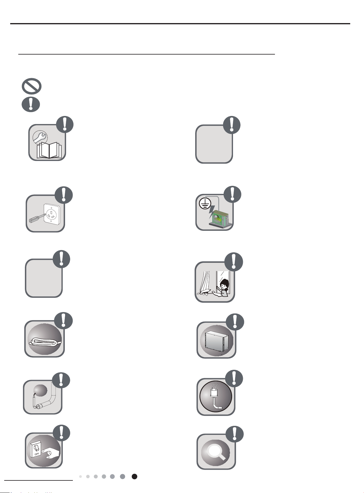
Follow this instruction to complete the
installation work.
Please carefully read this manual
before unit startup and service.
Installation should be conducted by
dealer or qualified personnel. Please
do not attempt to install the unit by
yourself. Improper handling may result
in water leakage, electric shock or fire
disaster etc.
Make sure the unit can be earthed
properly and soundly after plugging into
the socket so as to avoid electric shock.
Please do not connect the groundwire
to gas pipe, water pipe, lightning rod or
telephone line.
Before installation,please check if the
power supply is in accordance with
the requirements specified on the
nameplate.And also take care of the
power safety.
Be sure to use the excluxive
accessory and part to prevent the
water leakage,electric shock and fire
accidents.
Wire size of power cord should be large
enough The damaged power cord and
connection wire should be replaced by
exclusive cable.
Never fail to comply with the nitrigen
charge requirements. Charge nitrogen
when welding pipes.
Please firstly connect the wired
controller before energization,otherwise
wired controller can not be used.
If refrigerant leakage happens
during installation, please ventilate
immediately.Poisonous gas will emerge
if the refrigerant gas meets re.
After connecting the power cord, please
fix the electric box cover properly in
order to avoid accident.
Never short-circuit or cancel the
pressure switch to prevent unit damage.
Before using the unit, please. check
if the piping and wiring are correct
to avoid water leakage, refrigerant
leakage,electric shock, or re etc.
exclusive
N
2
Forbidden Items! It indicates that improper operation might lead to human casualty or sever injury.
Items need to be followed. It indicates that improper operation might lead to personal injury or property damage.
7. Safety Precautions
20
Installation and Maintenance
Service Manual
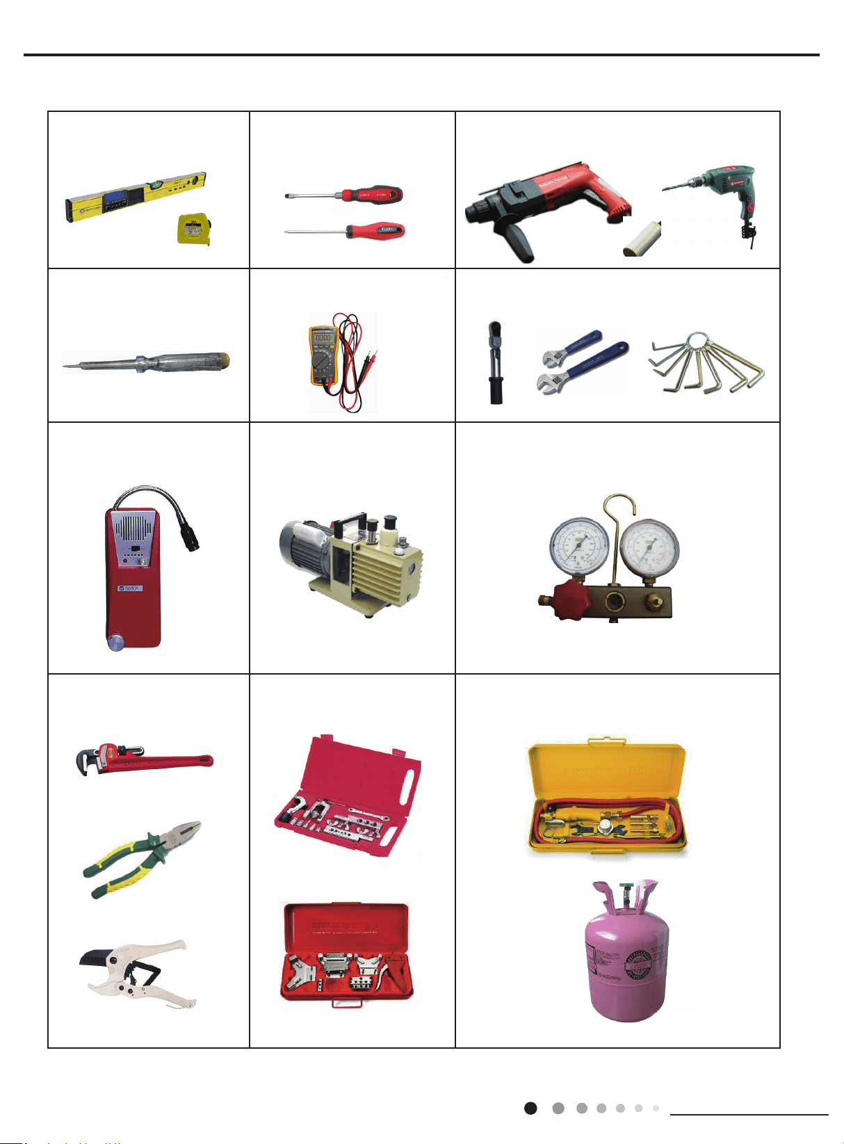
Main Tools for Installation and Maintenance
1. Level meter, measuring tape
4. Electroprobe
7. Electronic leakage detector
10. Pipe pliers, pipe cutter
2. Screw driver
5. Universal meter
8. Vacuum pump
11. Pipe expander, pipe bender
3. Impact drill, drill head, electric drill
6. Torque wrench, open-end wrench, inner
hexagon spanner
9. Pressure meter
12. Soldering appliance, refrigerant container
21
Installation and Maintenance
Service Manual
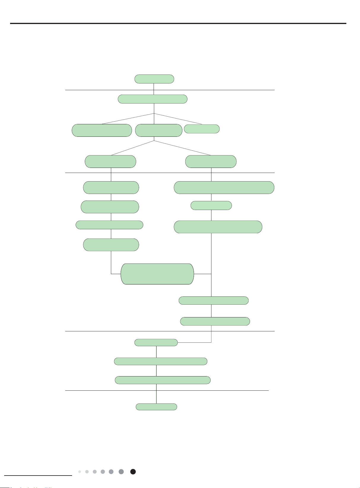
Preparation before installation
Prepare tools
Read the requirements
for electric connection
select installation
location
Select indoor unit
installation location
Install wall-mounting
frame, drill wall holes
Connect pipes of indoor
unit and drainage pipe
Connect wires of indoor unit
Connect wires of outdoor unit
Bind up pipes and
hang the indoor unit
Make the bound pipes pass
through the wall hole and then
connect outdoor unit
Neaten the pipes
Vacuum pumping and leakage detection
Check after installation and test operation
Finish installation
Note: this flow is only for reference; please find the more detailed installation steps in this section
.
Select outdoor unit
installation location
Install the support of outdoor unit
(select it according to the actual situation)
Install drainage joint of outdoor unit
(only for cooling and heating unit)
Connect pipes of outdoor unit
Start installation
Fix outdoor unit
Installation procedures
8. Installation Manual
22
Installation and Maintenance
Service Manual
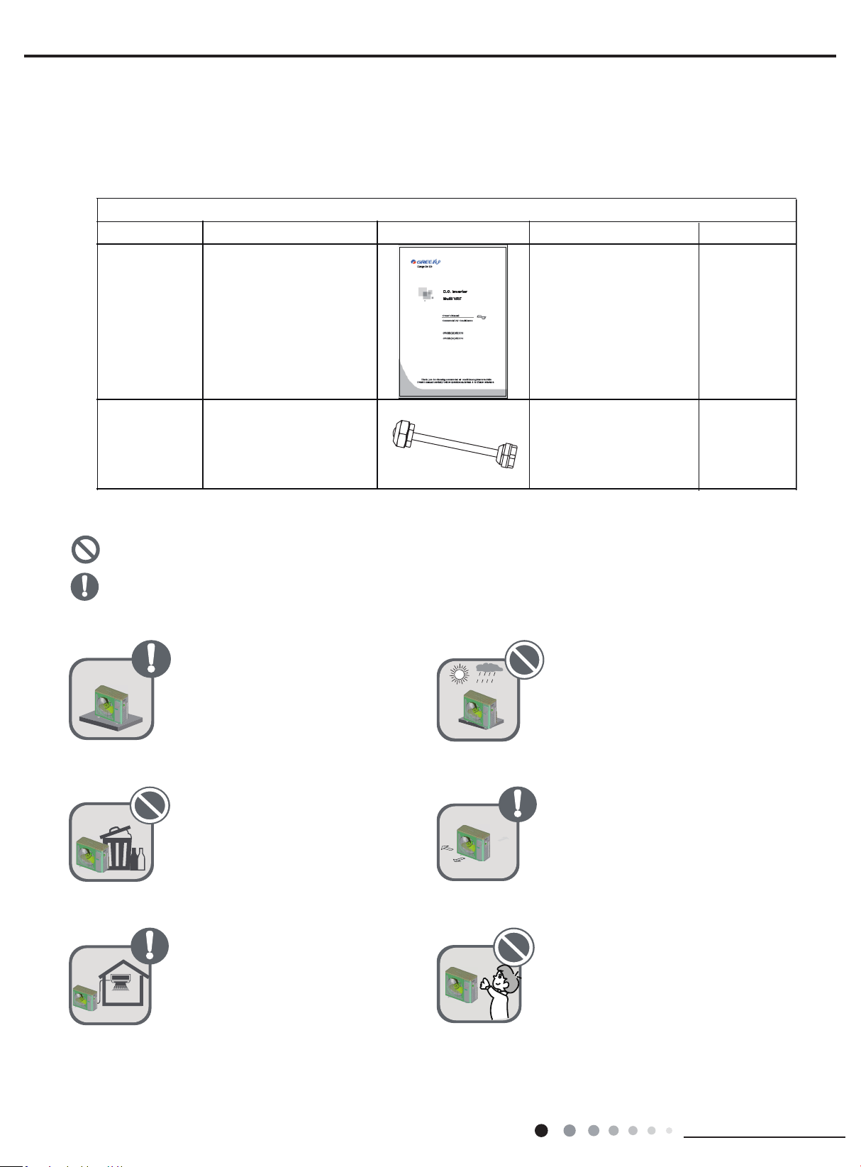
8.1.1 Standard parts
Please use the following standard parts supplied by GREE.
8.1.2 Selecting installation site
Forbidden Items! It indicates that improper operation might lead to human casualty or sever injury.
Items need to be followed. It indicates that improper operation might lead to personal injury or property damage.
Install the unit at a place where is
adequa to withstand the weight
of the unit and make sure the
unit would not shake or fall off.
Try to keep the unit away from
combustible, inammable and
corrosive gas or exhaust gas.
Leave some space for heat
exchanging and servicing so
as to guarantee unit normal
operation.
Never allow children to approach
to the unit and take measures
to prevent children touching the
unit.
Keep the indoor and outdoor
units close to each other as much
units close to each other as much
the pipe length and bends.
Never expose the unit under
direct sunshine and rainful.
install the unit at a place where
is against dust, typhoon and
earthquake.
8.1 Preparation before Installation
1
1
2
Namber name
Owner’s manual
Tube connector
subassy
18/24/36K:8; 42K:9
Pars of Outdoor Unit
picture
Quantity
Remark
23
Installation and Maintenance
Service Manual
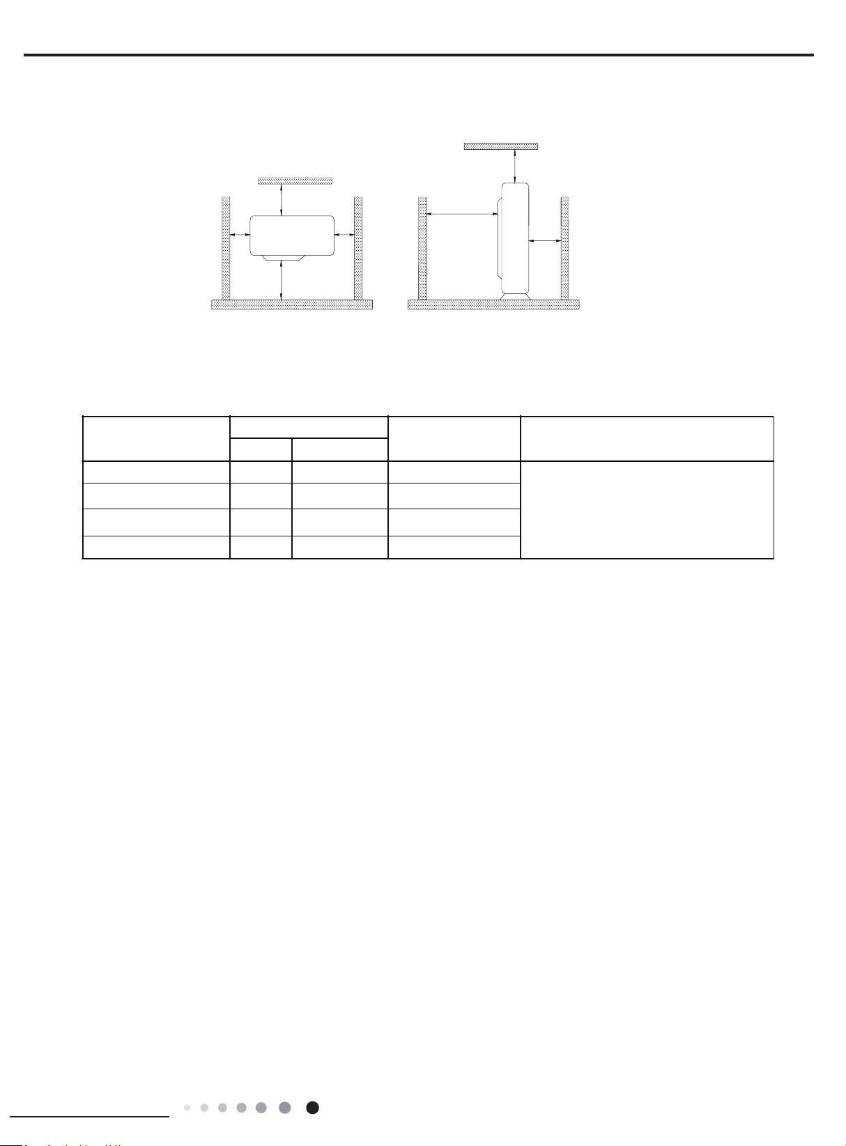
When the outdoor unit is totally surrounded by walls, the installation space of the unit should be as required in
Fig.1.
8.1.3 Piping Connection
The maximum pipe length is shown in the following table. When the distance between units (piping length) is out of the range listed below,
normal run of the unit can not be guaranteed.
Note:
①
Use water-proof insulating pipe.
②
Wall thickness of pipe: 0.5-1.0 mm;bearing pressure: 3.0MPa
③
The longer the connection pipe is, the more cooling and heating capacity will decrease.
>
19 2/3
>39 3/8
>78 3/4
>
19 2/3
>19 2/3
>
19 2/3
>78 3/4
unit:inch
Fig.1
M odel
ConnectingPipe(
inch
)
Max. Pipe length(ft
)
Max. Height Differ ence betw een
I ndoor Unit andOutdoor Unit (
ft
)Liqu id Gas
Ф 1/4 3/8
3/8
3/8
1/4
1/4
Φ 229.6
Ф 1/4 3/8Φ 164
24K
18K
36K
42K
ФФ 246.1
246.1ФФ
When the outdoor unit is above maximum
height difference between indoor and
outdoor units is up to 49.2ft; When the indoor
unit is above,maximum height difference
between indoor and outdoor units is up to
49.2ft.
24
Installation and Maintenance
Service Manual
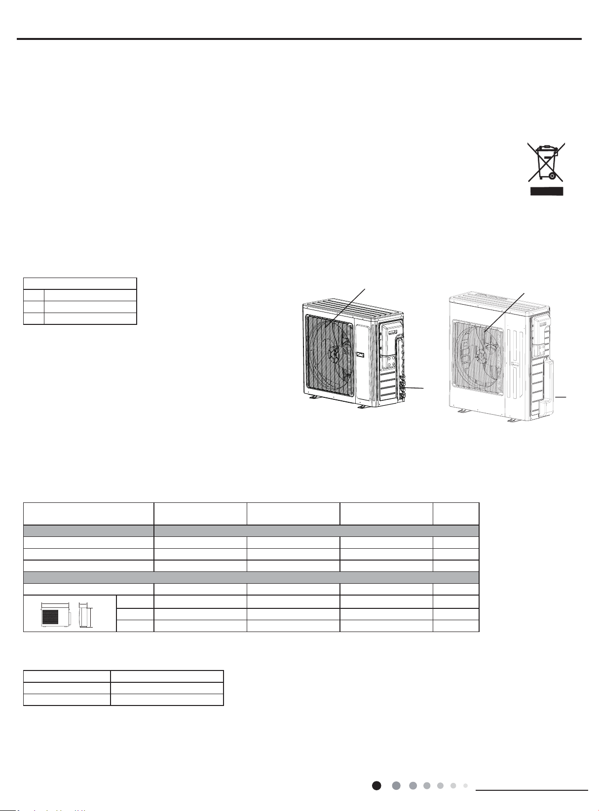
8.2.1 Outline and dimension of the outdoor unit
8.2 Installation Instruction
NAME OF PARTS
WARNING
● If the supply cord is damaged, it must be replaced by the manufacturer or its service agent or a similarly qualied
person in order to avoid a hazard.
● Be sure to cut off the power supply before cleaning the air conditioner; otherwise electricshock might happen.
● Wetting of air conditioner may cause the risk of electric shock. Make sure not to wash your air conditioner in any case.
● Volatile liquids such as thinner or gasoline will cause damage to the appearance of air conditioner. (Only use soft dry cloth moist cloth clean
the air conditioner cabinet).
● Do not dispose this product as unsorted municipal waste. Collection of such waste separately for special treatment is necessary.
● The temperature of refrigerant circuit will be high, please keep the interconnection cable away from the copper tube.
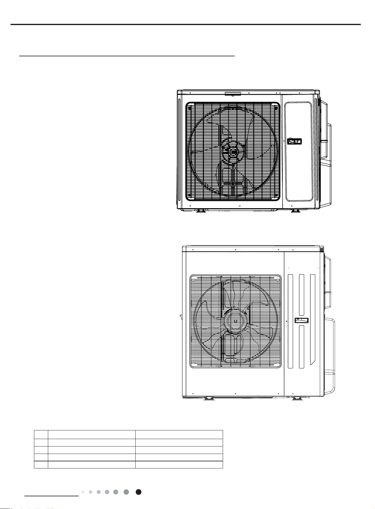
OUTDOOR UNIT
No. Description
1 Air outlet grille
2 Valve
Note: The above gures are only intended to be a simple
diagram of the appliance and may not correspond to
the appearance of the units that have been purchased
TECHNICAL DATA
MODE
MULTIU18HP230V1DO MULTIU24HP230V1DO
MULTIU36HP230V1DO
MULTIU42HP230V1DO
Electrical data
Electricity supply 208/230V,60HZ 208/230V,60HZ 208/230V,60HZ
Fuse or air switch 35 40 60 A
Minimum power cord section AWG10 AWG10 AWG8
Size and clearance
L 36 7/21 36 7/21 40 inch
P 14 61/64 14 61/64 17 21/64 inch
H 31 7/64 31 7/64 43 27/64 inch
OUTDOOR UNIT WORKING TEMPERATURE RANGE
OutdoorsideDB/WB(
O
c )
Maximum cooling 115°F(46°C)/-
Maximum heating 75.2°F(24°C)/-
11
2
2
P
L
H
18/24K 36/42K
25
Installation and Maintenance
Service Manual
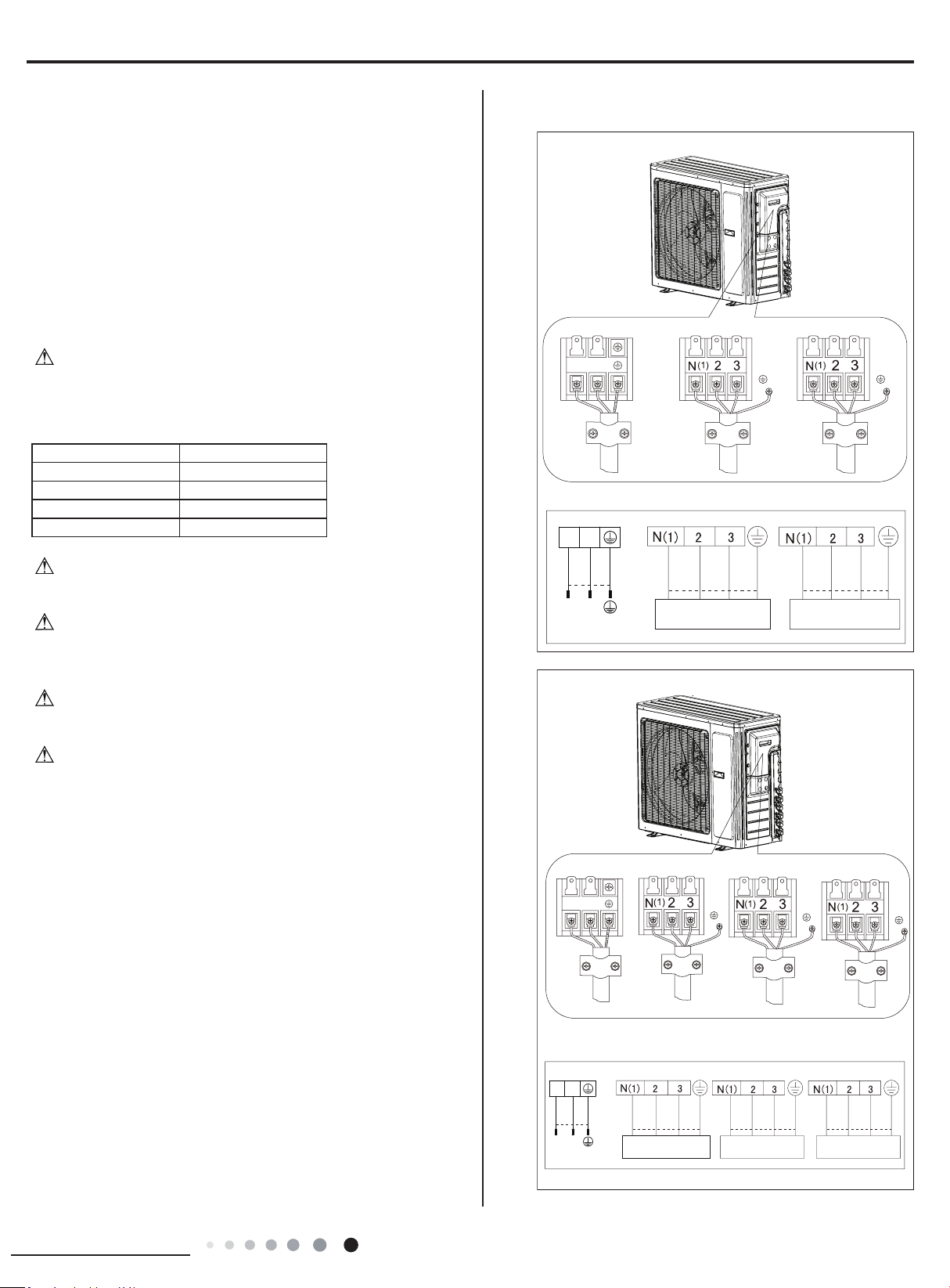
ELECTRICAL CONNECTIONS
1. Remove the handle at the right side plate of the outdoor unit (one
screw).
2. Remove the cable clamp, connect the power connection cable
with the terminal at the row of connection and fix the connection.
The tting line distributing must be consistent with the indoor unit.
terminal of line bank.Wiring should meet that of indoor unit.
3. Fix power connection wire by wire clamp.
4. Ensure wire has been xed well.
5. Install the handle.
Including an air switch with suitable capacity,please note the
following table. Air switch should be included magnet buckle and
heating buckle function, it can protect the circuit-short and overload.
(Caution: please do not use the fuse only for protect the circuit)
Air-conditioner Air switch capacity
MULTIU18HP230V1DO
35A
MULTIU24HP230V1DO
40A
MULTIU36HP230V1DO 60A
MULTIU42HP230V1DO 60A
An all-pole disconnection switch having a contact separation of
at least 3mm in all pole should be connected in xed wiring.
Wrong wire connection may cause malfunction of some
electric components.After fixing cable, ensure that leads between
connection to xed point have some space.
The connection pipes and the connectiong wirings of the unit A
and unit B must be corresponding to each other respective.
The appliance shall be installed in accordance with national
wiring regulations.
Note: the above gures are only intended to be a simple
diagram of the appliance and may not correspond to the
appearance of the units that have been purchased.
W
ƹ
ƹ
ƹ
ƹ
ƹ
ƹ
ƹ
ƹ
ƹ
ƹ
ƹ
ƹ
ƹ
ƹ
ƹ
ƹ
ƹ
ƹ
ƹ
ƹ
ƹ
W
ƹ
ƹ
ƹ
ƹ
ƹ
ƹ
ƹ
ƹ
ƹ
ƹ
ƹ
ƹ
ƹ
ƹ
ƹ
ƹ
ƹ
ƹ
ƹ
ƹ
ƹ
W
ƹ
ƹ
ƹ
ƹ
ƹ
ƹ
ƹ
ƹ
ƹ
ƹ
ƹ
ƹ
ƹ
ƹ
ƹ
ƹ
ƹ
ƹ
ƹ
ƹ
ƹ
W
ƹ
ƹ
ƹ
ƹ
ƹ
ƹ
ƹ
ƹ
ƹ
ƹ
ƹ
ƹ
ƹ
ƹ
ƹ
ƹ
ƹ
ƹ
ƹ
ƹ
ƹ
W
ƹ
ƹ
ƹ
ƹ
ƹ
ƹ
ƹ
ƹ
ƹ
ƹ
ƹ
ƹ
ƹ
ƹ
ƹ
ƹ
ƹ
ƹ
ƹ
ƹ
ƹ
MULTIU18HP230V1DO
To the power supply
To unit B
Power cord
To unit A
connecting
cable
L1
L2
Power cord
L1 L2
To the power supply
To unit A
MULTIU24HP230V1DO
connecting
connecting
cable
cable
To unit B
connecting
To unit C
cable
connecting
cable
INDOOR UNIT AINDOOR UNIT B
white
(blue)
white
(blue)
black
(brown)
red
(brown)
/
/
POWER
/
/
(yellow-
green)
green
(yellow-
green)
green
black white
(blue)
red
(brown)
(yellow-
green)
green
black
INDOOR UNIT AINDOOR UNIT B
white
(blue)
white
(blue)
black
(brown)
red
(brown)
/
/
POWER
/
/
(yellow-
green)
green
(yellow-
green)
green
blackwhite
(blue)
red
(brown)
(yellow-
green)
green
black
INDOOR UNIT C
white
(blue)
red
(brown)
(yellow-
green)
green
black
CBA
BA
26
Installation and Maintenance
Service Manual
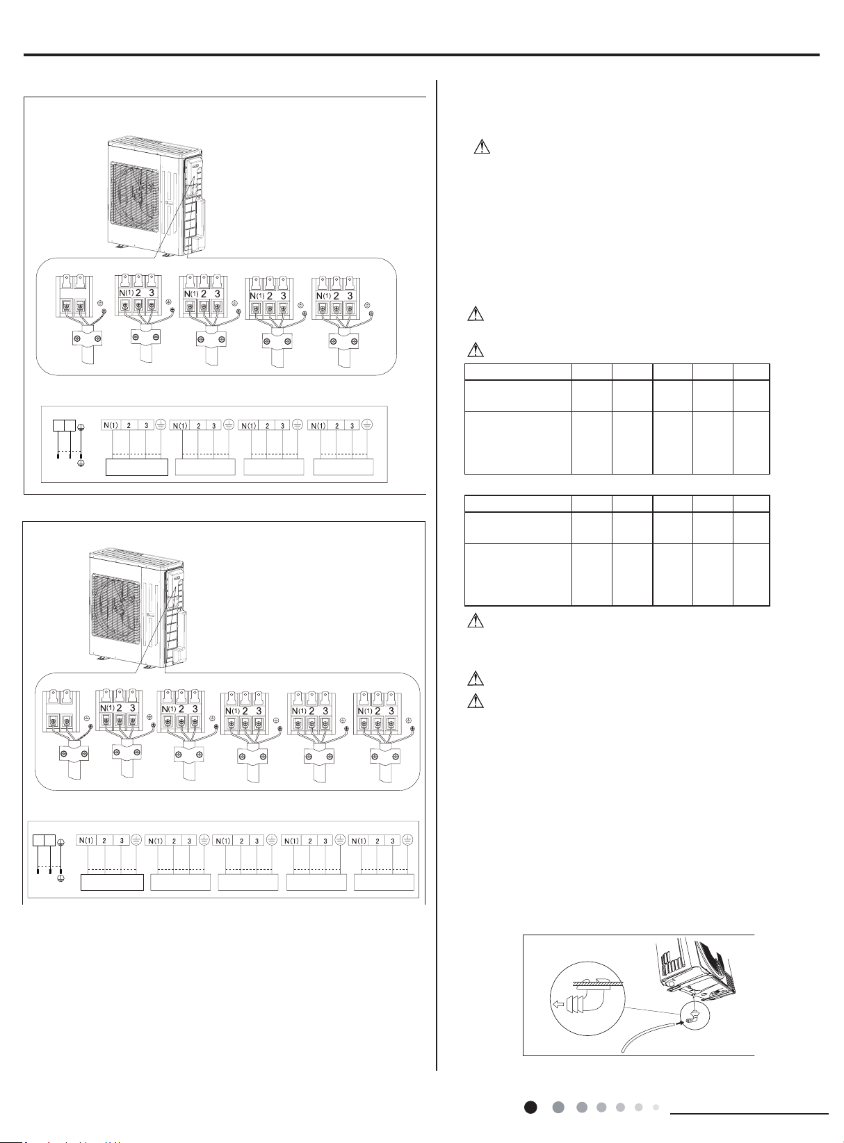
To the power supply
To unit A
connecting
cable
To unit B
connecting
To unit C
cable
connecting
cable
To unit D
connecting
cable
INDOOR UNIT AINDOOR UNIT B
white
(blue)
white
(blue)
black
(brown)
red
(brown)
/
/
POWER
/
/
(yellow-
green)
green
(yellow-
green)
green
black white
(blue)
red
(brown)
(yellow-
green)
green
black
INDOOR UNIT C
white
(blue)
red
(brown)
(yellow-
green)
green
black
C
INDOOR UNIT D
white
(blue)
red
(brown)
(yellow-
green)
green
black
DBA
Power cord
L1 L2
To the power supply
To unit A
connecting
To unit B
cable
connecting
To unit C
cable
connecting
To unit D
cable
connecting
cable
To unit E
connecting
cable
INDOOR UNIT AINDOOR UNIT B
white
(blue)
white
(blue)
black
(brown)
red
(brown)
/
/
POWER
/
/
(yellow-
green)
green
(yellow-
green)
green
black white
(blue)
red
(brown)
(yellow-
green)
green
black
INDOOR UNIT C
white
(blue)
red
(brown)
(yellow-
green)
green
black
C
INDOOR UNIT D
white
(blue)
red
(brown)
(yellow-
green)
green
black
D
INDOOR UNIT E
white
(blue)
red
(brown)
(yellow-
green)
green
black
EBA
Power cord
L1 L2
MULTIU36HP230V1DO
MULTIU42HP230V1DO
INSTALLING THE OUTDOOR UNIT
Location
Use bolts to secure the unit to a flat, solid floor.When
mounting the unit on a wall or the roof, make sure the support
is rmly secured so that it cannot move in the event of intense
vibrations or a strong
wind.
● Do not install the outdoor unit in pits or air vents
Installing the pipes
Use suitable connecting pipes and equipment for the
refrigerant R410A.
Models(ft)
18Kx2 24Kx2 24Kx3 36Kx2
36Kx3
Max. connection
pipe length
164 164
230 164 230
Max. connection
pipe length
(Simple one indoor
unit)
82 82 82 82
Models(ft) 36Kx4 42Kx2 42Kx3 42Kx4
42Kx5
pipe length
Max. connection
246 164 246 263 263
Max. connection
(Simple one indoor
unit)
pipe length
82 82 82
82 82
The refrigerant pipes must not exceed the maximum
heights 33 ft.(18x2&24x2&24x3) & 49 ft(36x2&36x3&36x4&42x2
&42x3&42x4&42x5)
Wrap all t he refrigerant pipes and joints.
Tighten the connections using two wrenches working in
opposite directions.
Caution: Installation Must be Performed in Accordance
with the NEC/CEC by Authorized Personnel Only.
Install the drain tting and the drain hose(for model with
heat pump only)
Condensation is produced and flows from the outdoor
unit when the appliance is operating in the heating mode.
In order not to disturb neighbours and to respect the
environment,install a drain tting and a drain hose to channel
the condensate water.Install the drain fitting and rubber
washer on the outdoor unit chassis and connect a drain hose
to it as shown in the gure.
W
ƹ
ƹ
ƹ
ƹ
ƹ
ƹ
ƹ
ƹ
ƹ
ƹ
ƹ
ƹ
ƹ
ƹ
ƹ
ƹ
ƹ
ƹ
ƹ
ƹ
ƹ
W
ƹ
ƹ
ƹ
ƹ
ƹ
ƹ
ƹ
ƹ
ƹ
ƹ
ƹ
ƹ
ƹ
ƹ
ƹ
ƹ
ƹ
ƹ
ƹ
ƹ
ƹ
W
ƹ
ƹ
ƹ
ƹ
ƹ
ƹ
ƹ
ƹ
ƹ
ƹ
ƹ
ƹ
ƹ
ƹ
ƹ
ƹ
ƹ
ƹ
ƹ
ƹ
ƹ
W
ƹ
ƹ
ƹ
ƹ
ƹ
ƹ
ƹ
ƹ
ƹ
ƹ
ƹ
ƹ
ƹ
ƹ
ƹ
ƹ
ƹ
ƹ
ƹ
ƹ
ƹ
W
ƹ
ƹ
ƹ
ƹ
ƹ
ƹ
ƹ
ƹ
ƹ
ƹ
ƹ
ƹ
ƹ
ƹ
ƹ
ƹ
ƹ
ƹ
ƹ
ƹ
ƹ
W
ƹ
ƹ
ƹ
ƹ
ƹ
ƹ
ƹ
ƹ
ƹ
ƹ
ƹ
ƹ
ƹ
ƹ
ƹ
ƹ
ƹ
ƹ
ƹ
ƹ
ƹ
82
27
Installation and Maintenance
Service Manual
Vacuum pump
Vacuum pump Vacuum pump
conversion joint
Connect to the
indoor unit
INDOOR
UNIT
Refrigerant fluid di
rection of fiow
3-way valve
inlet
2-w
ay valve
(8) Secure
(2)Turn
(7)Turn to open fully
(8) Secure
(2)Turn
(6) Open by 1/4 turn
(7)Turn to open fully
(8) Secure
(2)Turn
Valve cap
V
alve cap
Service
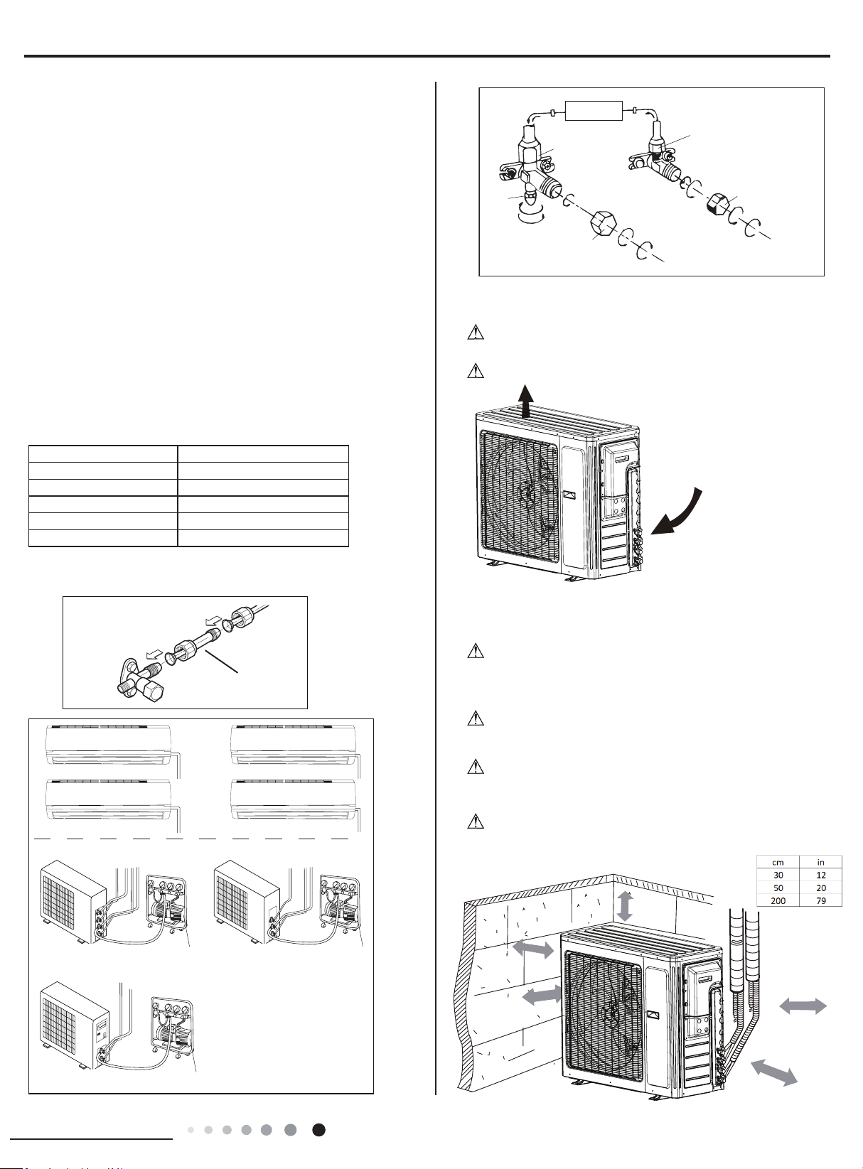
BLEEDING
Humid air left inside the refrigerant circuit can cause compressor
malfunction. After having connected the indoor and outdoor units,
bleed the air and humidity from the refrigerant circuit using a
vacuum pump.
(1) Unscrew and remove the caps from the 2-way and 3-way
valves.
(2) Unscrew and remove the cap from the service valve.
(3) Connect the vacuum pump hose to the service valve.
(4) Operate the vacuum pump for 10-15 minutes until an absolute
vacuum of 10 mm Hg has been reached.
(5) With the vacuum pump still in operation, close the low-pressure
knob on the vacuum pump coupling.Stop the vacuum pump.
(6) Open the 2-way valve by 1/4 turn and then close it after 10
seconds. Check all the joints for leaks using liquid soap or an
electronic leak device.
(7) Turn the body of the 2-way and 3-way valves. Disconnect the
vacuum pump hose.
(8) Replace and tighten all the caps on the valves.
Diameter (in) Twisting moment (N.m)
1/4
15-20
3/8
35-40
1/2 45-50
5/8 60-65
3/4 70-75
18/24/36/42K unit need to be installed the indoor unit
MAINTENANCE
Use suitable instruments for the refrigerant R410A.
● Do not use any other refrigerant than R410A.
Do not use mineral oils to clean the unit.
INSTALLATION DIMENSION DIAGRAM
The installation must be done by trained and qualied service
personnel with reliability according to this
manual.
Contact service center before installation to avoid the
malfunction due to unprofessional installation.
When picking up and moving the units, you must be guidedby
trained and qualied person.
appliance.
W
ƹ
ƹ
ƹ
ƹ
ƹ
ƹ
ƹ
ƹ
ƹ
ƹ
ƹ
ƹ
ƹ
ƹ
ƹ
ƹ
ƹ
ƹ
ƹ
ƹ
ƹ
W
ƹ
ƹ
ƹ
ƹ
ƹ
ƹ
ƹ
ƹ
ƹ
ƹ
ƹ
ƹ
ƹ
ƹ
ƹ
ƹ
ƹ
ƹ
ƹ
ƹ
ƹ
W
ƹ
ƹ
ƹ
ƹ
ƹ
ƹ
ƹ
ƹ
ƹ
ƹ
ƹ
ƹ
ƹ
ƹ
ƹ
ƹ
ƹ
ƹ
ƹ
ƹ
ƹ
W
ƹ
ƹ
ƹ
ƹ
ƹ
ƹ
ƹ
ƹ
ƹ
ƹ
ƹ
ƹ
ƹ
ƹ
ƹ
ƹ
ƹ
ƹ
ƹ
ƹ
ƹ
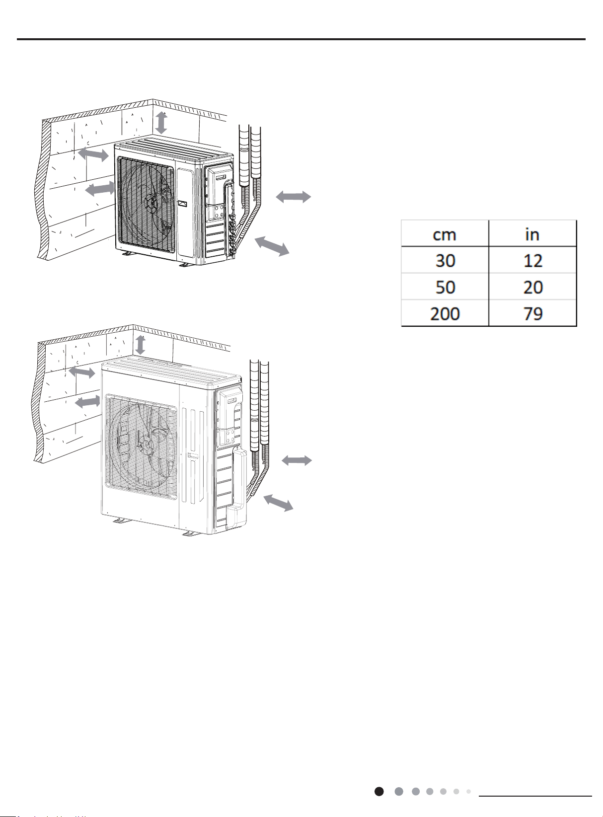
W
Ensure that the recommened space is left around
the
ƹ
ƹ
ƹ
ƹ
ƹ
ƹ
ƹ
ƹ
ƹ
ƹ
ƹ
ƹ
ƹ
ƹ
ƹ
ƹ
ƹ
ƹ
ƹ
ƹ
ƹ
W
ƹ
ƹ
ƹ
ƹ
ƹ
ƹ
ƹ
ƹ
ƹ
ƹ
ƹ
ƹ
ƹ
ƹ
ƹ
ƹ
ƹ
ƹ
ƹ
ƹ
ƹ
MULTIU18HP230V1DO
Space to the cover
200cm
30cm
(Air inlet side)
or abov
e
50cm
or
S
above
e
(Air outlet side)
pace to th
or above
wall
or more
30cm
or above
Space to the cover
50c
m
28
Installation and Maintenance
Service Manual
MULTIU24HP230V1DO
MULTIU36HP230V1DO MULTIU42HP230V1DO
Space to the cover
200cm
5
30cm
(Air inlet side)
0cm
or abov
e
Sp
or above
ace to the
(Air outlet side)
or above
wa
ll
30cm
or above
moreor
Space to the cover
50c
m
Space to the cover
200cm
30cm
(Air inlet side)
or abov
e
(Air outlet side)
or above
or more
30cm
or above
Space to the cover
50cm
or above
50c
m
29
Installation and Maintenance
Service Manual
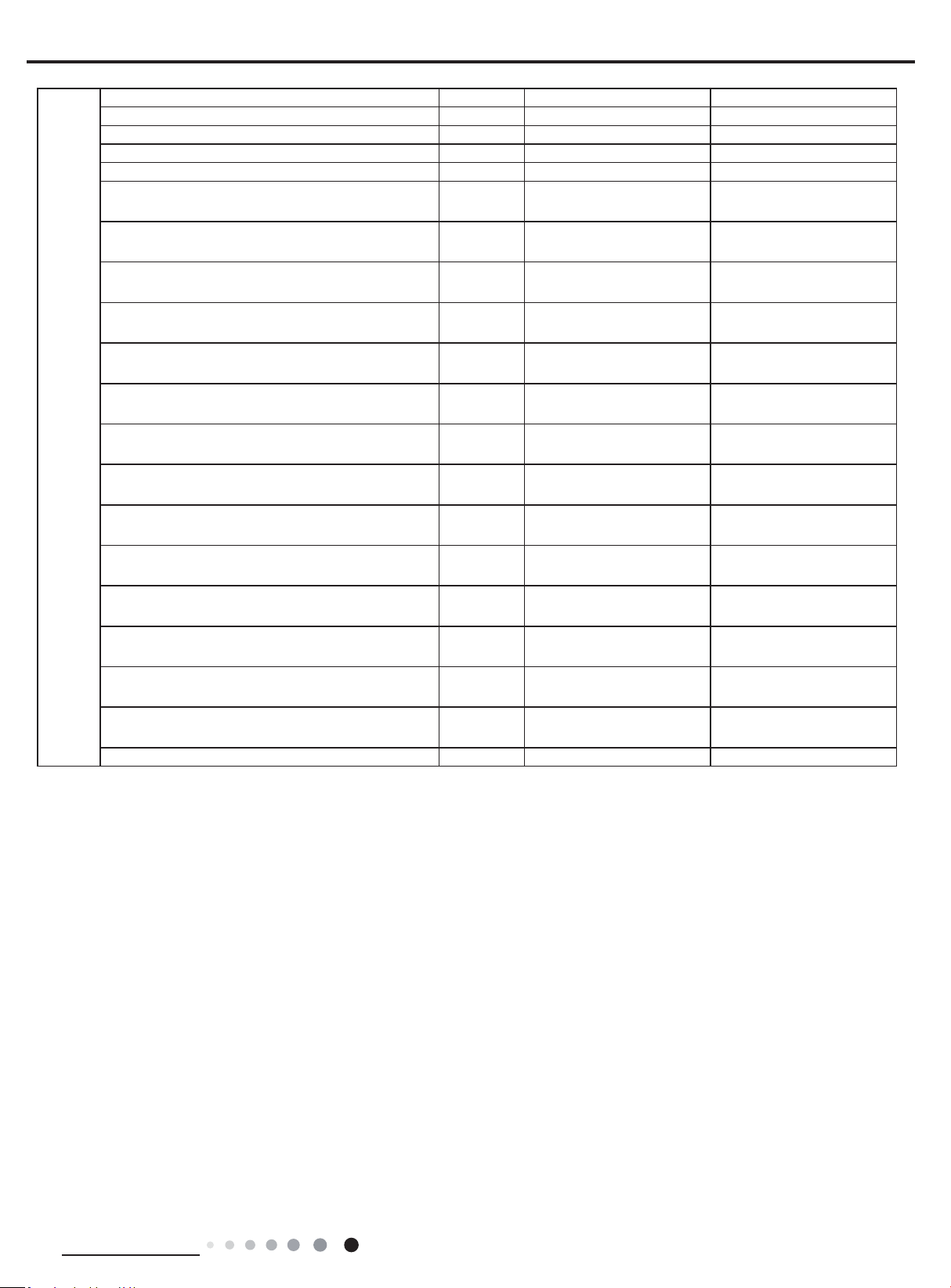
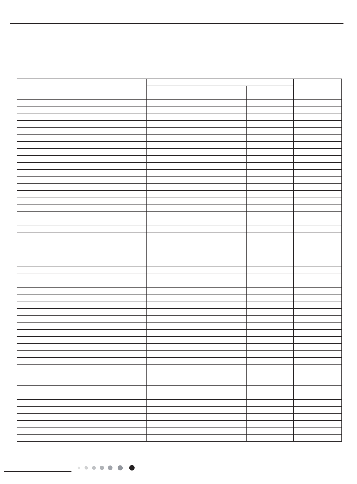
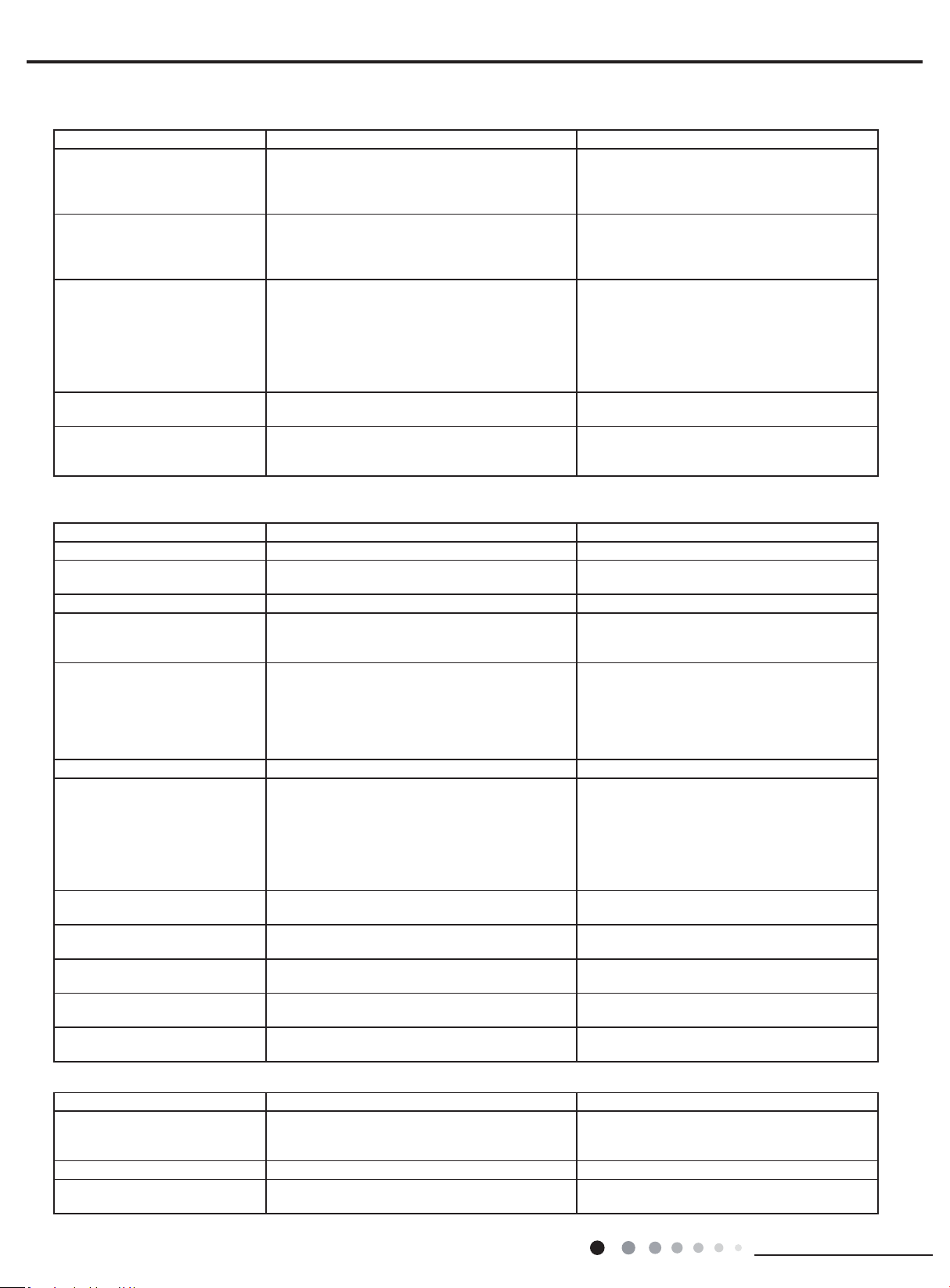
▲ The error code will be displayed on the wired controller and the main board of the outdoor unit The meaning of each error.
Name of malfunction
The indicator display Indoor display
Yellow light Red light Green light
Compressor runs Flash once
Defrost Flash twice H1
Anti-freezing protection Flash 3 times E2
IPM protection Flash 4 times H5
AC over-current protection Flash 5 times E5
Over-burden protection Flash 6 times H4
Compressor exhaust high temperature protection Flash 7 times E4
Compressor overload protection Flash 8 times H3
Power protection Flash 9 times L9
EEPROM reads and write protection Flash 11 times
Low PN voltage protection Flash 12 times PL
Over voltage protection for PN Flash 13 times PH
PFC protection Flash 14 times HC
PFC module temperature protection Flash 15 times oE
Low pressure protection Flash 17 times E3
High pressure protection Flash 18 times E1
Limit/decline frequency(electric current) Flash 1 times
Frequency limit
(
exhaust) Flash 2 times
Frequency limit(Over-burden) Flash 3 times
Outdoor ambient sensor malfunction Flash 6 times F3
Outdoor tube sensor malfunction Flash 5 times F4
Exhaust sensor malfunction Flash 7 times F5
Attain the temperature of switch on Flash 8 times
Frequency limit(power) Flash 13 times
Outdoor fan malfunction Flash 14 times
Frequency limit(PFC module temperature) Flash 15 times
PFC module sensor malfunction Flash 16 times oE
Liquid pipe temperature sensor malfunction of A Flash 17 times
Gas pipe temperature sensor malfunction of A Flash 18 times
Liquid pipe temperature sensor malfunction of B Flash 19 times
Gas pipe temperature sensor malfunction of B Flash 20 times
Liquid pipe temperature sensor malfunction of C Flash 21 times
Gas pipe temperature sensor malfunction of C Flash 22 times
Liquid pipe temperature sensor malfunction of D Flash 23 times
Gas pipe temperature sensor malfunction of D Flash 24 times
Liquid pipe temperature sensor malfunction of E Flash 25 times
Gas pipe temperature
sensor malfunction of E Flash 26 times
Exit of the condenser tube sensor malfunction Flash 27 times
Correspondence is normal
Flash 7
times(n=indoor unit
number)
Communication failure between indoor unit and
outdoor unit
Often bright
(
indoor unit all Communication failure)
Indoor ambient sensor malfunction F1
Indoor evaporate sensor malfunction F2
Mode conict E7
Accept uorine mode Fo
Jumper cap malfunction protection C5
9.1 Malfunction Indicator
9. Troubleshooting
30
Installation and Maintenance
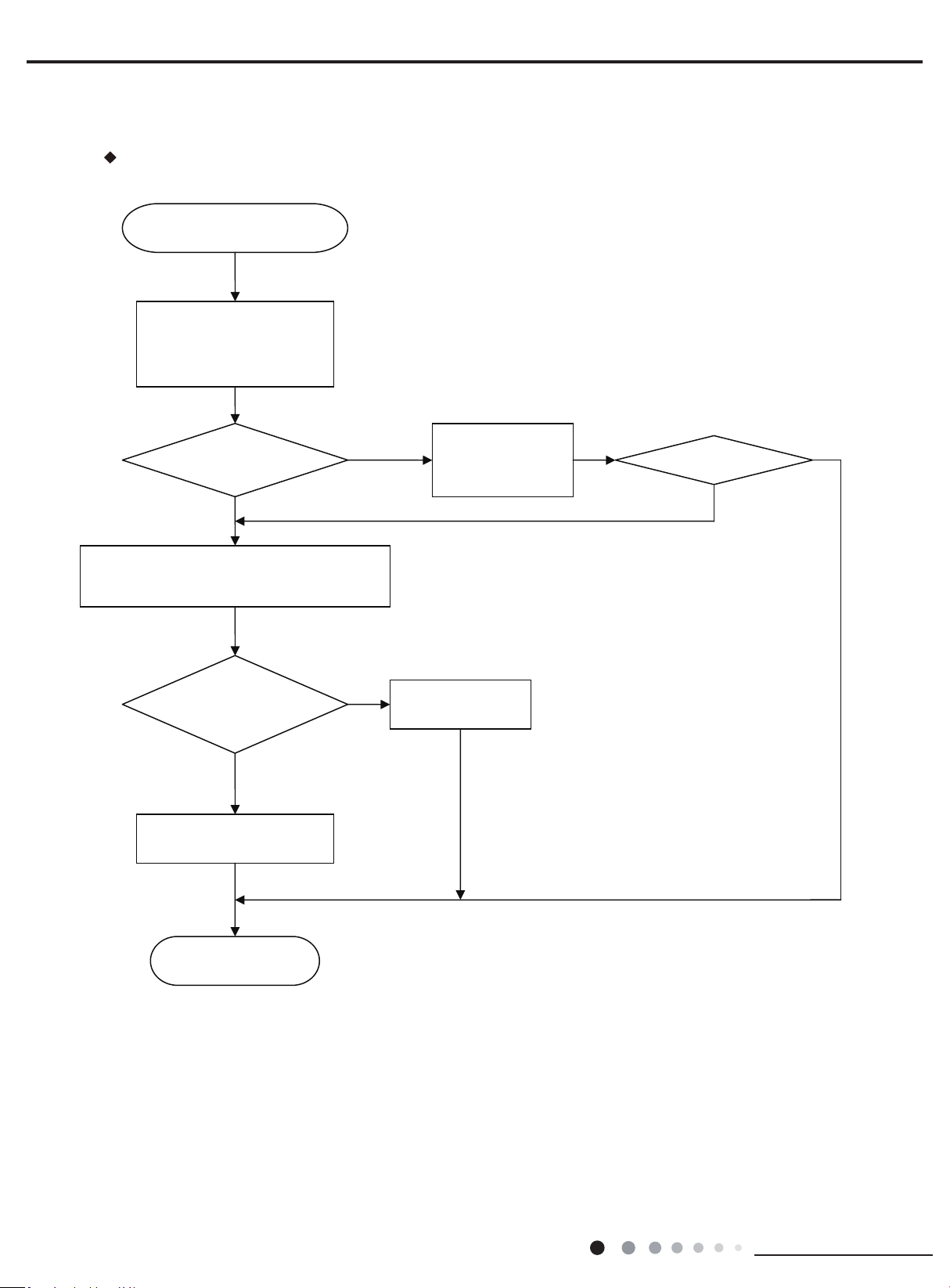
Service Manual
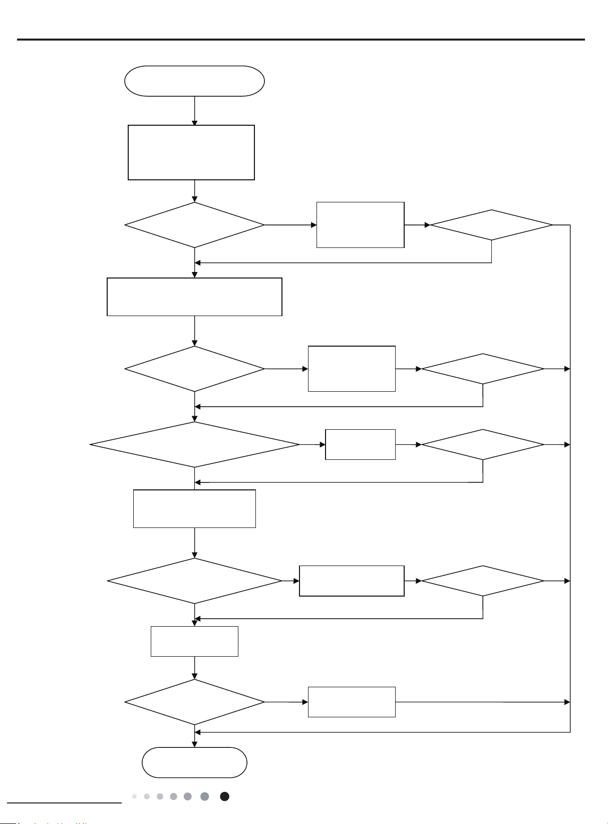
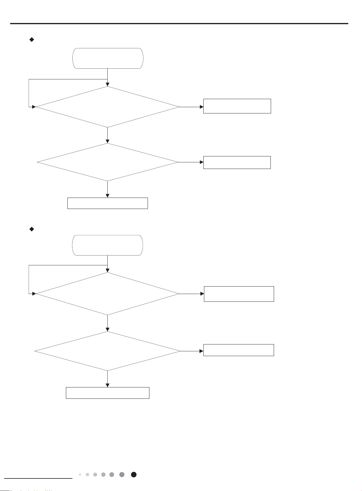
Eliminate the malfunction
End
Communication malfunction of some
indoor units
De-energize, check the connection
wire of indoor and outdoor unit and
the wire of the eletric box is
connected correctly
N
N
N
Connected correctly
Reconnect according to
the wiring diagram
Y
N
Y
De-energize, change the communication wire of the well-
communicated indoor unit and malfunction indoor unit,
then energize the unit and wait for 3min
The malfunction indoor unit
resumes normal
Replace outdoor
mainboard
Replace the mainboard of the
malfunction indoor unit
Malfunction display: E6 Communication malfunction
9.2 Malfunction Checking and Elimination
31
Installation and Maintenance
Service Manual
Eliminate the malfunction
Eliminate the malfunction
Eliminate the malfunction
Eliminate the malfunction
End
N
N
N
N
N
N
N
N
Y
Y
Y
Y
Y
Y
Y
Y
Y
All the indoor units appear
communication malfunction
De-energize, check the connection
wire of indoor and outdoor unit and
the wire of the eletric box is
connected correctly
Connected correctly?
Reconnect according to
the wiring diagram
Connected correctly?
Reconnect according to
the wiring diagram
De-energize, check if the connection wire between
the outdoor mainboard and the filter board
according to the wiring diagram
The connection wire is broken?
Replace the
connection wire
Check if there is power input
bewtween the netrual wire and live
wire of the outdoor mainboard
There is power input?
Replace the filter board of
the outdoor unit
Resume communication?
Replace the outdoor
mainboard
Replace indoor
mainboard
32
Installation and Maintenance
Service Manual
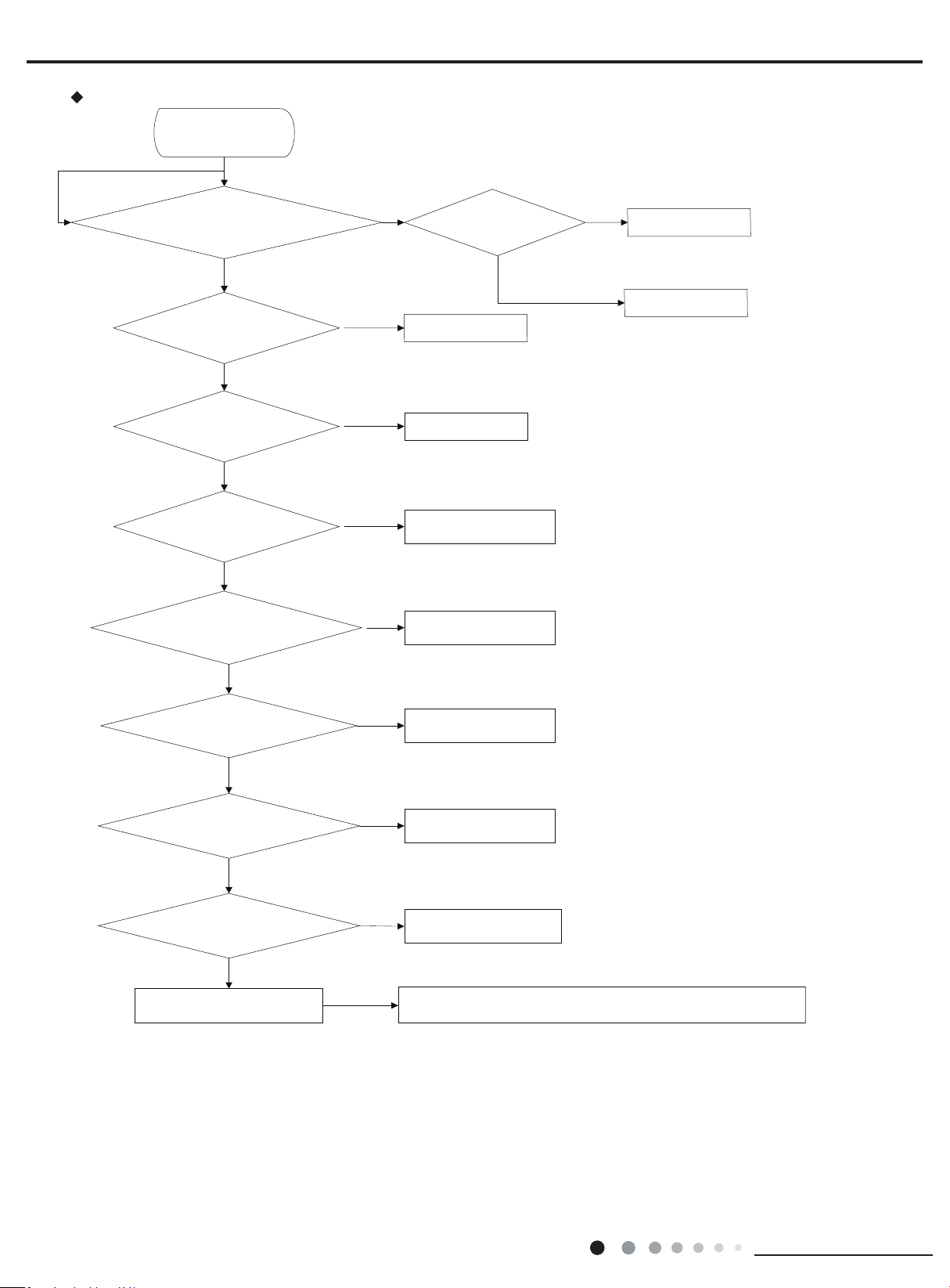
Malfunction display: E1 Compressor High Pressure Protection
Mainly check the inlet an
d
outlet of main pipe connecting with each indoor unit and
capillary of indoor and outdoor units.Replace the parts like filter,capillary and so on.
Check if indoor unit fan and outdoor unit fan
run
Check if swing louver of indoor unit is
completely open
High pressure protection
Y
N
Check if the pressure is really high pressure with the
measurement of a manometer
Replace the outdoor
unit mainboard
Replace pressure switch
Check if operation mode of indoor unit is
properly set
N
N
Y
Y
Y
Y
Check if gas valve and liquid valve are
completely open
Refer to Instruction
Manual of indoor unit
Check if the panel of outdoor unit is
firmly closed?
N
N
Completely open the
valve
Close the panel
Check if the air return and supply from heat
exchanger of indoor unit and outdoor unit is
smooth
Remove the barrier
Measure the fan motor and
signal input
Measure swing motor and
signal input
N
N
N
System pipeline is blocked
Y
Y
Y
Check if there is filth blockage to indoor/
outdoor filter or heat exchange fin
Refer to Care and Maintenance
N
Y
Y
N
Check if pressure switch
is abnormal
33
Installation and Maintenance
Service Manual
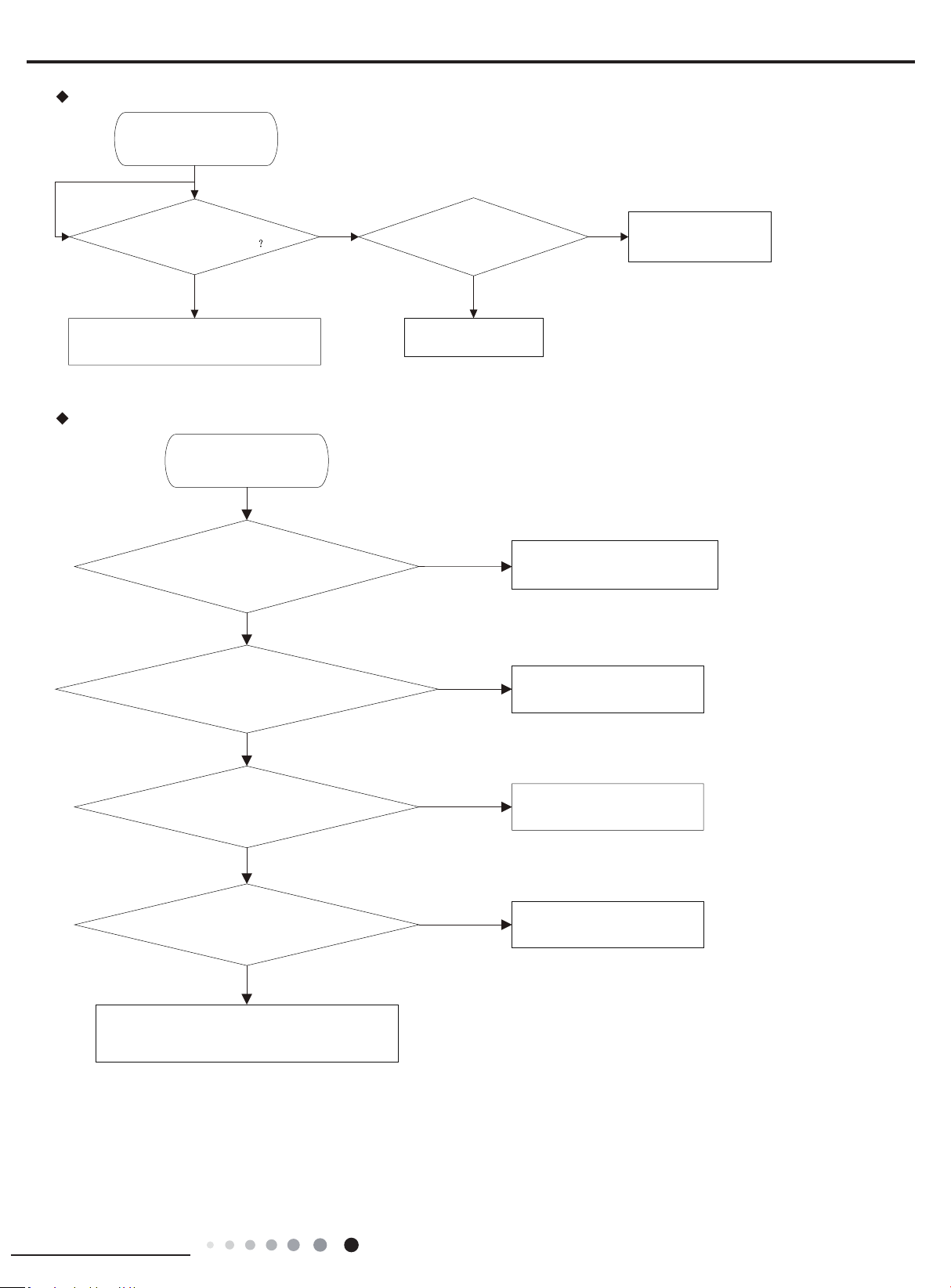
Malfunction display: E4 Compressor Exhaust High Temperature Protection
N
Y
Y
N
Y
Measure if compressor’s discharge
temperature has reached 115℃
System pipeline leaks so complementation is needed.
Please add refrigerant according to the amount
specified in the nameplate
Measure if temperature sensor’s
resistance value is correct
Replace the outdoor
unit mainboard
Replace relevant discharge
temperature sensor
Discharge temperature protection
Malfunction display: E5 Compressor Overheat
N
Y
Y
Y
Y
Y
N
N
N
Check if compressor’s connection line is
properly connected
Adjust compressor’s connection line
Check if current value is higher than the protector’s setting Replace overcurrent protector
If unit’s high pressure is normall
Refer to high pressure protection
If voltage is normal
Contact the power supply
company
Replace mainboard
Abnormal overcurrent
34
Installation and Maintenance
Service Manual
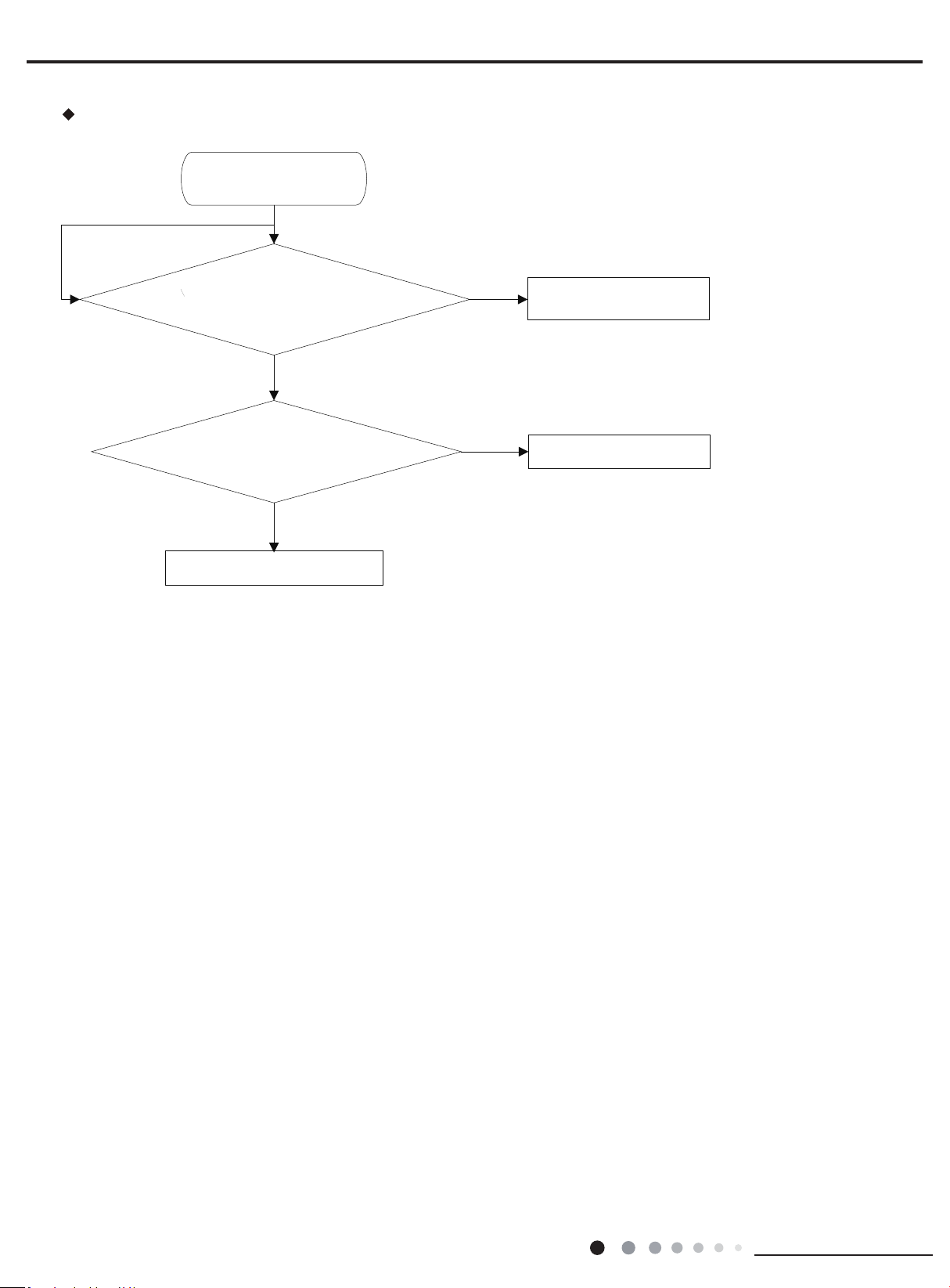
Malfunction display: F2 Failure of Evaporator Temp. Sensor
Check if the plug of the temperature sensor is correctly
connected with socket on the mainboar d
N
Remove the sensor to check if the resistance value is ok
N
Y
Y
Y
Replace mainboard of the indoor uint
Check the direction of the plug and
socket
Replace temperature sensor
Failure of condenser Temp sensor
35
Installation and Maintenance
Service Manual
Malfunction display: F3 Failure of Outdoor Ambient Sensor
N
N
Y
Y
Y
Failure of outdoor Ambient sensor
Check if the plug of the temperature sensor is correctly
connected with socket on the mainboard
Remove the sensor to check if the resistance value is ok
Replace mainboard of the indoor uint
Replace temperature sensor
Check the direction of the plug
and socket
Malfunction display: F5 Failure of Exhaust Temp. Sensor
N
N
Y
Y
Y
Failure of Exhaust Temp. sensor
Check if the plug of the temperature sensor is correctly
connected with socket on the mainboard
Remove the sensor to check if the resistance value is ok
Replace mainboard of the indoor uint
Replace temperature sensor
Check the direction of the plug
and socket
36
Installation and Maintenance
Service Manual
Possible Causes Discriminating Method (Air conditioner Status) Troubleshooting
Set temperature is improper Observe the set temperature on remote controller Adjust the set temperature
Rotation speed of the IDU fan
motor is set too low
Small wind blow Set the fan speed at high or medium
Filter of indoor unit is blocked Check the lter to see it's blocked Clean the lter
Installation position for indoor unit
and outdoor unit is improper
Check whether the installation postion is proper
according to installation requirement for air
conditioner
Adjust the installation position, and install the
rainproof and sunproof for outdoor unit
Refrigerant is leaking
Discharged air temperature during cooling is
higher than normal discharged wind temperature;
Discharged air temperature during heating is
lower than normal discharged wind temperature;
Unit's pressure is much lower than regulated
range
Find out the leakage causes and deal with it.
Add refrigerant.
Malfunction of 4-way valve Blow cold wind during heating Replace the 4-way valve
Malfunction of capillary
Discharged air temperature during cooling is
higher than normal discharged wind temperature;
Discharged air temperature during heating is
lower than normal discharged wind temperature;
Unit't pressure is much lower than regulated
range. If refrigerant isn’t leaking, part of capillary
is blocked
Replace the capillary
Flow volume of valve is
insufcient
The pressure of valves is much lower than that
stated in the specication
Open the valve completely
Malfunction of horizontal louver Horizontal louver can’t swing
Refer to point 3 of maintenance method for
details
Malfunction of the IDU fan motor The IDU fan motor can’t operate
Refer to troubleshooting for H6 for maintenance
method in details
Malfunction of the ODU fan motor The ODU fan motor can't operate
Refer to point 4 of maintenance method for
details
Malfunction of compressor Compressor can't operate
Refer to point 5 of maintenance method for
details
9.3 Maintenance Method for Normal Malfunction
1. Air Conditioner Can't be Started Up
2. Poor Cooling (Heating) for Air Conditioner
3. Horizontal Louver Can't Swing
Possible Causes Discriminating Method (Air conditioner Status) Troubleshooting
No power supply, or poor
connection for power plug
After energization, operation indicator isn’t bright
and the buzzer can't give out sound
Conrm whether it's due to power failure. If yes,
wait for power recovery. If not, check power
supply circuit and make sure the power plug is
connected well.
Wrong wire connection between
indoor unit and outdoor unit,
or poor connection for wiring
terminals
Under normal power supply circumstances,
operation indicator isn't bright after energization
Check the circuit according to circuit diagram
and connect wires correctly. Make sure all
wiring terminals are connected rmly
Electric leakage for air conditioner
After energization, room circuit breaker trips off at
once
Make sure the air conditioner is grounded
reliably
Make sure wires of air conditioner is connected
correctly
Check the wiring inside air conditioner. Check
whether the insulation layer of power cord is
damaged; if yes, place the power cord.
Model selection for air switch is
improper
After energization, air switch trips off Select proper air switch
Malfunction of remote controller
After energization, operation indicator is bright,
while no display on remote controller or buttons
have no action.
Replace batteries for remote controller
Repair or replace remote controller
Possible Causes Discriminating Method (Air conditioner Status) Troubleshooting
Wrong wire connection, or poor
connection
Check the wiring status according to circuit
diagram
Connect wires according to wiring diagram to
make sure all wiring terminals are connected
rmly
Stepping motor is damaged Stepping motor can't operate Repair or replace stepping motor
Main board is damaged
Others are all normal, while horizontal louver
can't operate
Replace the main board with the same model
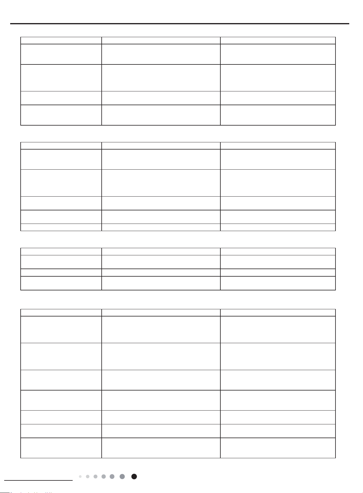
37
Installation and Maintenance
Service Manual
7. Abnormal Sound and Vibration
Possible causes Discriminating method (air conditioner status) Troubleshooting
When turn on or turn off the unit,
the panel and other parts will
expand and there's abnormal
sound
There's the sound of "PAPA"
Normal phenomenon. Abnormal sound will
disappear after a few minutes.
When turn on or turn off the unit,
there's abnormal sound due
to ow of refrigerant inside air
conditioner
Water-running sound can be heard
Normal phenomenon. Abnormal sound will
disappear after a few minutes.
Foreign objects inside the indoor
unit or there're parts touching
together inside the indoor unit
There's abnormal sound fro indoor unit
Remove foreign objects. Adjust all parts'
position of indoor unit, tighten screws and stick
damping plaster between connected parts
Foreign objects inside the outdoor
unit or there're parts touching
together inside the outdoor unit
There's abnormal sound fro outdoor unit
Remove foreign objects. Adjust all parts'
position of outdoor unit, tighten screws and
stick damping plaster between connected parts
Short circuit inside the magnetic
coil
During heating, the way valve has abnormal
electromagnetic sound
Replace magnetic coil
Abnormal shake of compressor Outdoor unit gives out abnormal sound
Adjust the support foot mat of compressor,
tighten the bolts
Abnormal sound inside the
compressor
Abnormal sound inside the compressor
If add too much refrigerant during maintenance,
please reduce refrigerant properly. Replace
compressor for other circumstances.
6. Air Conditioner is Leaking
Possible causes Discriminating method (air conditioner status) Troubleshooting
Drain pipe is blocked Water leaking from indoor unit
Eliminate the foreign objects inside the drain
pipe
Drain pipe is broken Water leaking from drain pipe Replace drain pipe
Wrapping is not tight
Water leaking from the pipe connection place of
indoor unit
Wrap it again and bundle it tightly
5. Compressor Can't Operate
Possible causes Discriminating method (air conditioner status) Troubleshooting
Wrong wire connection, or poor
connection
Check the wiring status according to circuit
diagram
Connect wires according to wiring diagram to
make sure all wiring terminals are connected
rmly
Capacity of compressor is
damaged
Measure the capacity of fan capacitor with an
universal meter and nd that the capacity is out of
the deviation range indicated on the nameplate of
fan capacitor.
Replace the compressor capacitor
Power voltage is a little low or
high
Use universal meter to measure the power supply
voltage. The voltage is a little high or low
Suggest to equip with voltage regulator
Coil of compressor is burnt out
Use universal meter to measure the resistance
between compressor terminals and it's 0
Repair or replace compressor
Cylinder of compressor is blocked Compressor can't operate Repair or replace compressor
4. ODU Fan Motor Can't Operate
Possible causes Discriminating method (air conditioner status) Troubleshooting
Wrong wire connection, or poor
connection
Check the wiring status according to circuit
diagram
Connect wires according to wiring diagram to
make sure all wiring terminals are connected
rmly
Capacity of the ODU fan motor is
damaged
Measure the capacity of fan capacitor with an
universal meter and nd that the capacity is out of
the deviation range indicated on the nameplate of
fan capacitor.
Replace the capacity of fan
Power voltage is a little low or
high
Use universal meter to measure the power supply
voltage. The voltage is a little high or low
Suggest to equip with voltage regulator
Motor of outdoor unit is damaged
When unit is on, cooling/heating performance
is bad and ODU compressor generates a lot of
noise and heat.
Change compressor oil and refrigerant. If no
better, replace the compressor with a new one
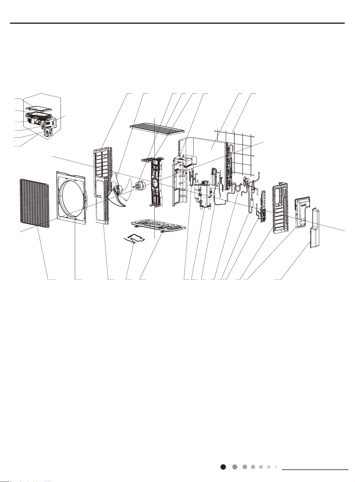
38
Installation and Maintenance
Service Manual
MULTIU18HP230V1DO MULTIU24HP230V1DO
1
2
3
4
5
6
7
8
9
10
11
12
13
14
15
16
17
18
19
20
21
22
23
24
25
26
27
28
29
The component picture is only for reference; please refer to the actual product.
10. Exploded View and Parts List
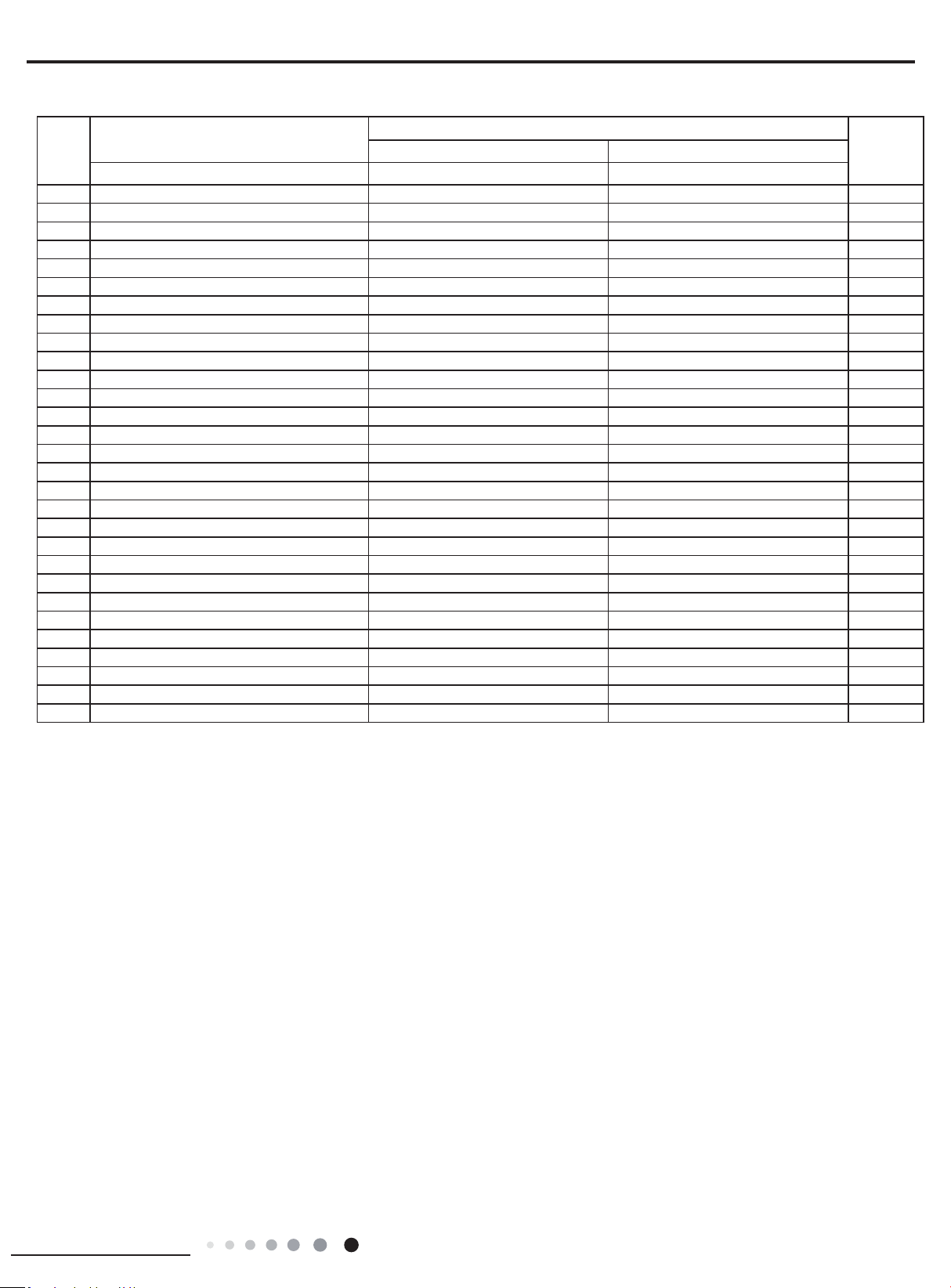
39
Installation and Maintenance
Service Manual
Above data is subject to change without notice.
NO.
Description
Part Code
Qty
MULTIU18HP230V1DO MULTIU24HP230V1DO
Product code CB228W09400 CB228W09500
1 Front Grill 016004000006 016004000006 1
2 Cabinet 0143543901P 0143543901P 1
3 Front Side Plate Sub-Assy 017101060007 017101060007 1
4 Electrical Heater (Chassis) 7651000413 7651000413 1
5 Base Plate Sub-Assy 017000060044P 017000060044P 1
6 Electromagnetic Valve Sub-assy 030025060020 030025060020 1
7 Compressor and Fittings 009001000013 009001000013 1
8 Flash Vaporizer Assy 000036060003 000036060003 1
9 Inhalation Tube Sub-assy 030010060420 030010060420 1
10 4-way Valve Assy 030152060055 030152060055 1
11 Valve Support Assy 030163060001 030163060003 1
12 Right Side Plate 0131410000902P 0131410000902P 1
13 Handle 26233053 26233053 1
14 Valve Cover 200087000006 200087000006 1
15 Rear Grill 01574100003 01574100003 1
16 Condenser Assy 011002060151 011002060151 1
17 Clapboard Sub-Assy 017021060037 017021060037 1
18 Motor Support Sub-Assy 017012000017 017012000017 1
19 Top Cover Sub-Assy 000051060049 000051060049 1
20 Brushless DC Motor 15010400000107 15010400000107 1
21 Axial Flow Fan Sub-Assy 10333017 10333017 1
22 Left Side Plate 01305043P 01305043P 1
23 Electric Box Assy 100002060834 100002060797 1
24 Terminal Board 42200006001301 42200006001301 1
25 Terminal Board Support sub-assy 017041060005A 017041060005A 1
26 Radiator 4901305201 4901305201 1
27 Main Board 300027060170 300027060012 1
28 Electric Box Cover Sub-Assy 02603217A 02603217A 1
29 Terminal Board 422000060015 422000060015 2/3
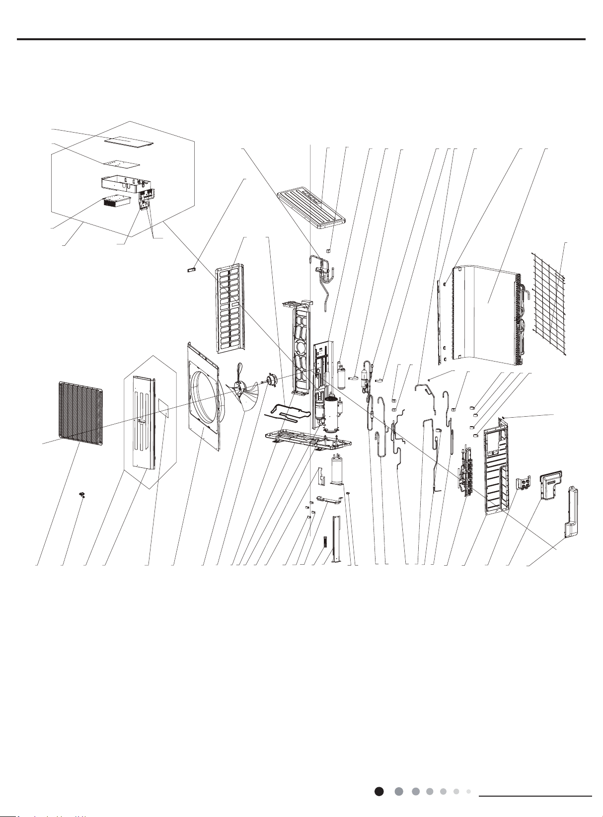
40
Installation and Maintenance
Service Manual
1
2
3
4
5
6
7
8
9
10
11
12
13
14
16
15
17
19
20
21
22
23
25
27
28
31
32
30
29
42
43
44
45
47
48
49
50
53
54
55
57
37
58
24
26
39
51
46
52
41
40
38
36
35
34
33
56
18
59
60
61
62
MULTIU36HP230V1DO
The component picture is only for reference; please refer to the actual product.
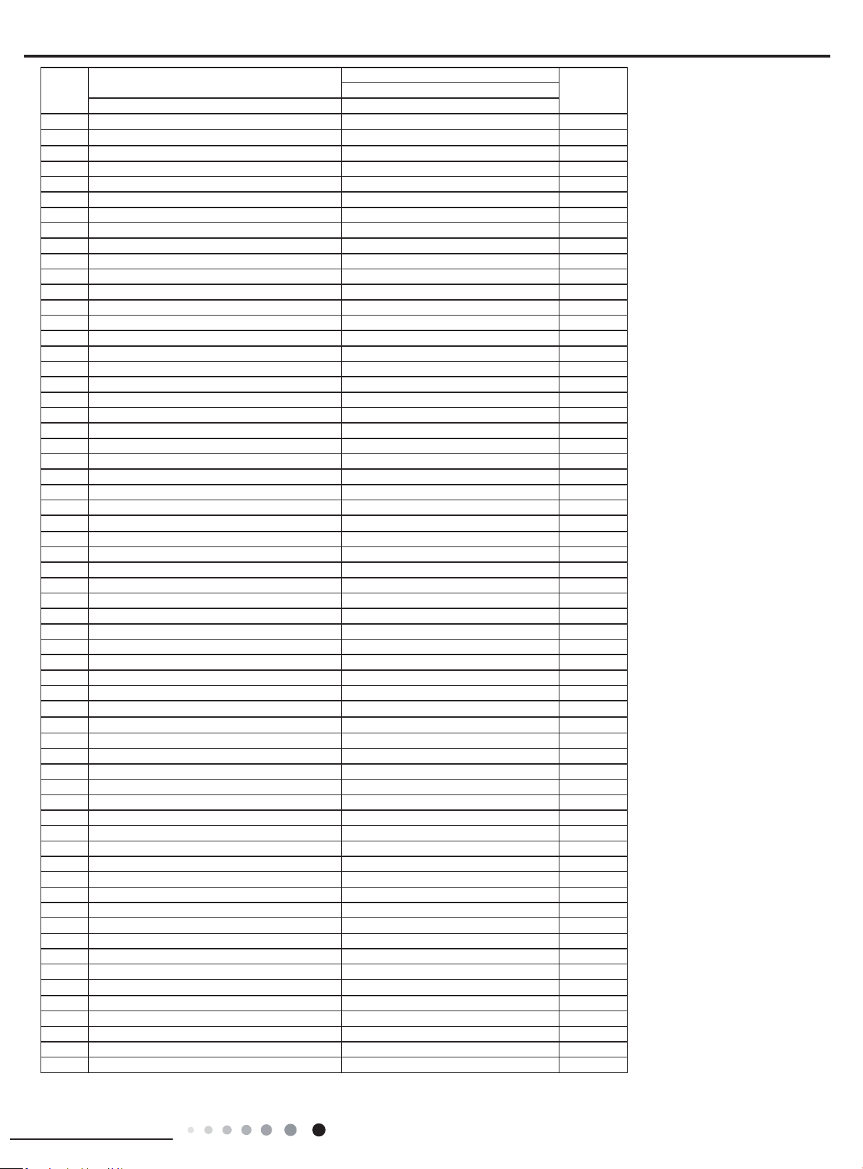
41
Installation and Maintenance
Service Manual
Above data is subject to change without notice.
NO.
Description
Part Code
QtyMULTIU36HP230V1DO
Product code CB228W09600
1 Front Grill 016004060003 1
2 Drainage Joint 26113009 1
3 Front Side Plate Sub-Assy 017101060008P 1
4 Front Side Plate Sub-Assy 017101060008 1
5 Insulated Board (Cover of Electric Box) 20113003 1
6 Cabinet 01435007P 1
7 Axial Flow Fan 10335014 1
8 Brushless DC Motor 1570280000409 1
9 Motor Support Sub-Assy 017012060043 1
10 Base Plate Sub-Assy 017000060108P 1
11 Compressor and Fittings 00204100030 1
12 Retaining Plate Sub-Assy 017032000118P 1
13 Supporting Board 0189410008902P 1
14 Tube Clip 021400053P 2
15 Litter Liquid Pipe(Rubber Loop) 76518218 2
16 Supporting Board Sub-assy 017056000201P 1
17 Electrical Heater 7651521242 1
18 Supporting Board Sub-assy 017056060224P 1
19 Accumulator 07424100031 1
20 Rubber Band 76510006 5
21 Oil Separator Sub-Assy 030079060004 1
22 Inhalation Tube Sub-Assy 030010060207 1
23 Electromagnetic Valve Sub-assy 030025060016 1
24 Electric Expansion Valve Sub-Assy 030026060045 1
25 Electric Expand Valve Fitting 43000345 1
26 Electromagnetic Valve Sub-assy 030025060014 1
27 Valve Support Assy
030163060005 1
28 Right Side Plate 0131410002702P 1
29 Wiring Cover Sub-assy 000224060003 1
30 Handle Assy 000223000003 1
31 Valve Cover 200087000005 1
32 Wiring Clamp 26115004
1
33 Electric Expand Valve Fitting 43000344 1
34 Electric Expand Valve Fitting 4300034411 1
35 Electric Expand Valve Fitting 4300034412 1
36 Electric Expand Valve Fitting 4300034414 1
37 Electric Box Assy 100002060835 1
38 Magnet Coil 4304000404 1
39 fusible plug 035222000004 1
40 Magnet Coil 4304000449 1
41 Magnet Coil 4304000447 1
42 Rear Grill 1574100007 1
43 Condenser Assy 011002060110 3
44 Toggle Switch Sheath 26905207 1
45 Condenser support plate 01895242 1
46 Connection Pipe Sub-assy 030062060112 1
47 Tube Clip 0214000521 1
48 Pressure Protect Switch 4602000603 1
49 Securing clip 02263702 1
50 Gas-liquid Separator 07223048 1
51 Clapboard Sub-Assy 017021060106 1
52 Magnet Coil 4300040029 1
53 Top Cover 0125500901P 1
54 4-way Valve Assy 030152060041 1
55 Handle 26233053 1
56 Electrical Heater 7651000417 1
57 Left Side Plate 01305064P 1
58 Electric Box Cover 012020060060 1
59 Main Board 300027060190 1
60 Radiator 4901800000203 1
61 Terminal Board 42200006001201 1
62 Terminal Board 422000060015 4
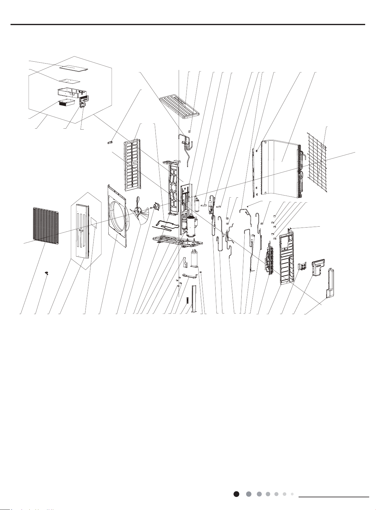
42
Installation and Maintenance
Service Manual
1
2
3
4
5
6
7
8
9
10
11
12
13
14
16
15
17
19
20
21
22
23
25
27
28
31
32
30
29
42
43
44
45
47
48
49
50
53
54
55
57
61
62
63
58
24
26
39
51
46
52
41
40
38
37
36
35
34
33
56
18
59
60
MULTIU42HP230V1DO
The component picture is only for reference; please refer to the actual product.

43
Installation and Maintenance
Service Manual
Above data is subject to change without notice.
NO.
Description
Part Code
QtyMULTIU42HP230V1DO
Product code CB228W09700
1 Front Grill 016004060003 1
2 Drainage Joint 26113009 1
3 Front Side Plate Sub-Assy 017101060008P 1
4 Front Side Plate Sub-Assy 017101060008 1
5 Insulated Board (Cover of Electric Box) 20113003 1
6 Cabinet 01435007P 1
7 Axial Flow Fan 10335014 1
8 Brushless DC Motor 1570280000409 1
9 Motor Support Sub-Assy 017012060043 1
10 Base Plate Sub-Assy 017000060108P 1
11 Compressor and Fittings 00204100030 1
12 Retaining Plate Sub-Assy 017032000118P 1
13 Supporting Board 0189410008902P 1
14 Tube Clip 021400053P 2
15 Litter Liquid Pipe(Rubber Loop) 76518218 2
16 Supporting Board Sub-assy 017056000201P 1
17 Electrical Heater 7651521242 1
18 Supporting Board Sub-assy 017056060224P 1
19 Accumulator 07424100031 1
20 Rubber Band 76510006 5
21 Oil Separator Sub-Assy 030079060004 1
22 Inhalation Tube Sub-Assy 030010060207 1
23 Electromagnetic Valve Sub-assy 030025060016 1
24 Electric Expansion Valve Sub-Assy 030026060045 1
25 Electric Expand Valve Fitting 43000345 1
26 Electromagnetic Valve Sub-assy 030025060014 1
27 Valve Support Assy 030163060002 1
28 Right Side Plate 0131410002702P 1
29 Wiring Cover Sub-assy 000224060003 1
30 Handle Assy 000223000003 1
31 Valve Cover 200087000005 1
32 Wiring Clamp 26115004
1
33 Electric Expand Valve Fitting 43000344 1
34 Electric Expand Valve Fitting 4300034411 1
35 Electric Expand Valve Fitting 4300034412 1
36 Electric Expand Valve Fitting 4300034414 1
37 Electric Expand Valve Fitting 4300034413 1
38 Magnet Coil 4304000404 1
39 fusible plug 035222000004 1
40 Magnet Coil 4304000449 1
41 Magnet Coil 4304000447 1
42 Rear Grill 1574100007 1
43 Condenser Assy 011002060110 3
44 Toggle Switch Sheath 26905207 1
45 Condenser support plate 01895242 1
46 Connection Pipe Sub-assy 030062060112 1
47 Tube Clip 0214000521 1
48 Pressure Protect Switch 4602000603 1
49 Securing clip 02263702 1
50 Gas-liquid Separator 07223048 1
51 Clapboard Sub-Assy 017021060106 1
52 Magnet Coil 4300040029 1
53 Top Cover 0125500901P 1
54 4-way Valve Assy 030152060041 1
55 Handle 26233053 1
56 Electrical Heater 7651000417 1
57 Left Side Plate 01305064P 1
58 Electric Box Cover 012020060060 1
59 Main Board 300027060011 1
60 Radiator 4901800000203 1
61 Electric Box Assy 100002060833 1
62 Terminal Board 42200006001201 1
63 Terminal Board 422000060015 5
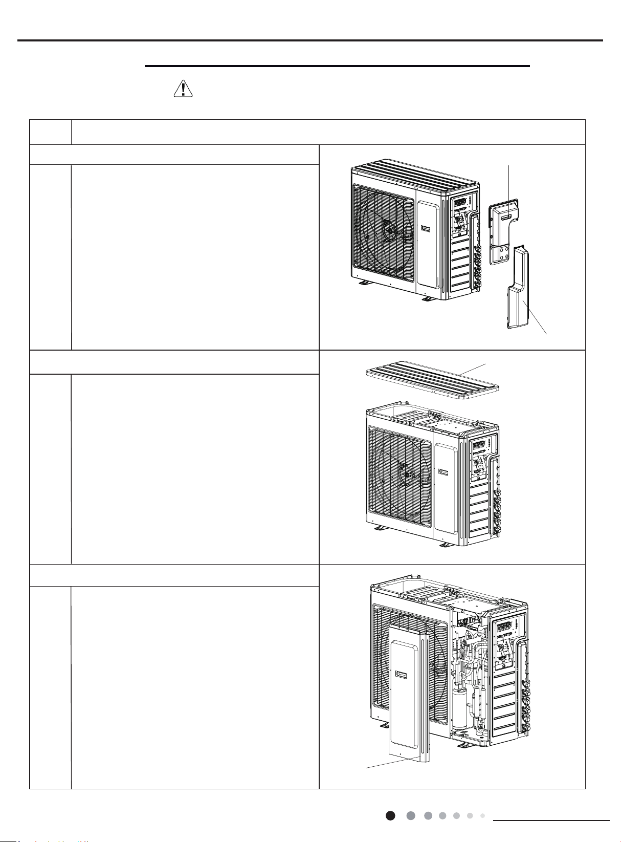
44
Installation and Maintenance
Service Manual
Steps Procedure
top cover
Remove the screws connecting the top cover with
outer case, right side plate and left side plate; lift the
top cover upwards to remove it.
1. Remove the handle and valve cover
2. Remove top cover
3.Remove front side plate
front side plate
Remove the screws connecting the front side plate
with chassis and middle isolation sheet,and then
remove the front side plate
MULTIU18HP230V1DO MULTIU24HP230V1DO
handle
valve cover
Remove the screws connicting the handle with right
side plate and then remove the handle.
Remove the screws connicting the valve cover and
then remove the valve cover.
11. Removal Procedure
Warning: Be sure to wait for a minimum of 20 minutes after turning off all
power supplies and discharge the refrigerant completely before removal.
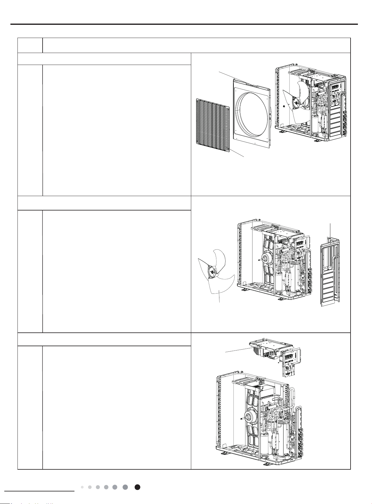
45
Installation and Maintenance
Service Manual
Steps Procedure
grille
right side plate
Remove the screws connecting the right side plate
with electric box assy, valve support, chassis and
condenser side plate, and then remove the right
side plate.
Remove the 4 screws connecting the grille and
outer case, and then remove the panel grille.
5.Remove right side plate and blade
4.Remove grille and cabinet
cabinet
Remove nuts fixing axial flow blade with wrench,
and then remove the axial ow blade.
blade
electric box assy
1.Remove the grounding wire screw on the electric
box assy and then remove the grounding wire.
2.Disconnect the wiring terminals of reactor,
compressor, high and low pressure switch,
compressor overload protector, temperature sensor,
outdoor fan motor and 4-way valve. (See g 2)
Note: keep pressing the circlip when disconnecting
the wiring terminal of reactor; keep pressing the
retainer when disconnecting other wiring terminals.
3.Remove the wire inside the wiring groove.
6. Remove electric box assy
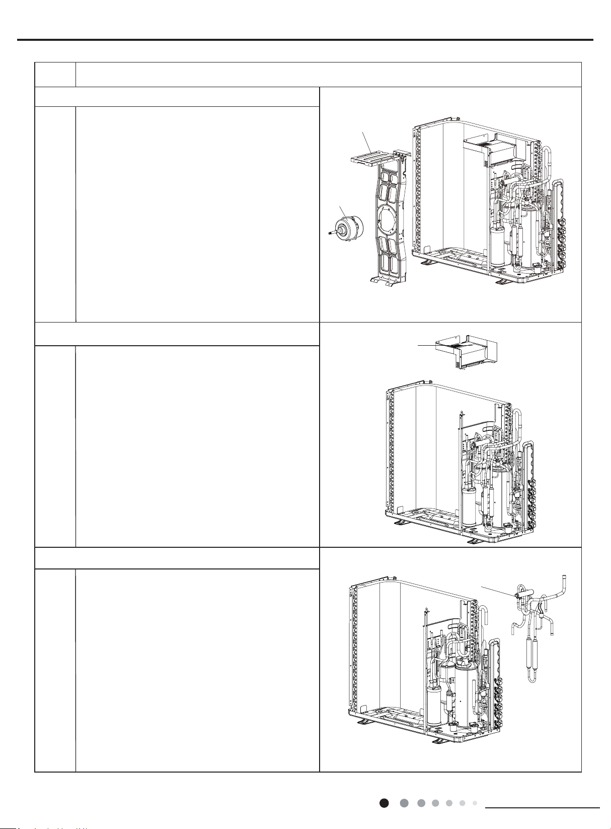
46
Installation and Maintenance
Service Manual
Steps Procedure
motor support
clapboard sub-assy
Remove 4 screws fixing clapboard sub-assy,and
then remove the clapboard sub-assy.
8. Remove clapboard sub-assy
7. Remove motor and motor support
motor
Remove 4 screws xing motor,and then remove the
motor;
Remove 2 screws connecting motor support and
chassis, loosen damper block and then remove the
motor support.
4-way valve
Unsolder the spot weld between 4-way valve and
vapour liquid separator, compressor cut-off valve
sub-assy and condenser, and then remove the 4-way
valve.
Note: When unsoldering the spot weld, wrap the
4-way valve with wet cloth completely to avoid
damage to valve due to high temperature.
9. Remove 4-way valve
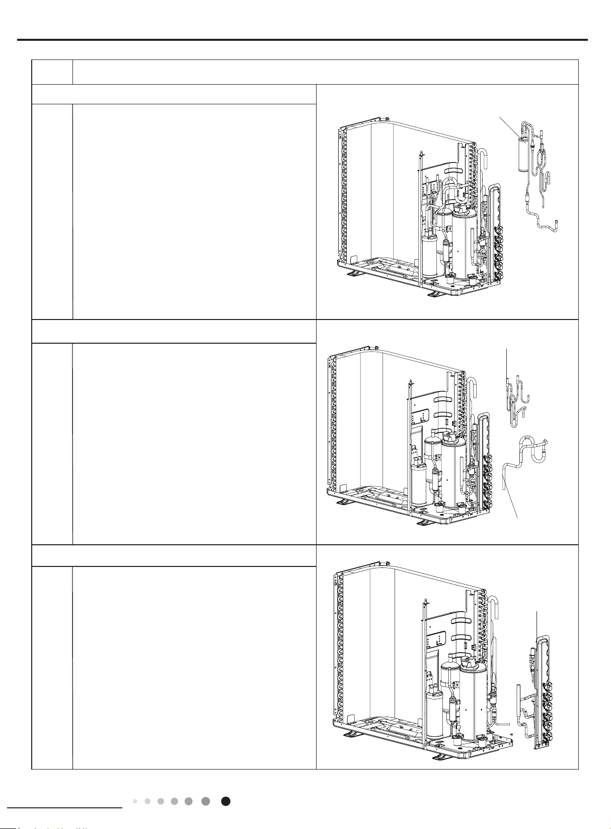
47
Installation and Maintenance
Service Manual
Steps Procedure
electromagnetic valve sub-assy
inhalation tube sub-assy
Unsolder all spot welds electromagnetic valve sub-
assy and then remove the electromagnetic valve sub-
assy.
Unsolder all spot welds inhalation tube sub-assy and
then remove the inhalation tube sub-assy.
11. Remove electromagnetic valve sub-assy and inhalation
tube sub-assy
10. Remove ash vaporizer assy
ash vaporizer assy
Unsolder all spot welds cflash vaporizer assy, and
then remove the ash vaporizer assy.
valve support
Unsolder all spot welds connected with valve support
and then remove the valve support.
Note:When unsoldering the spot weld, wrap the gas
valve and liquid valve with wet cloth completely to
avoid damage to valve due to high temperature.
12. Remove valve support
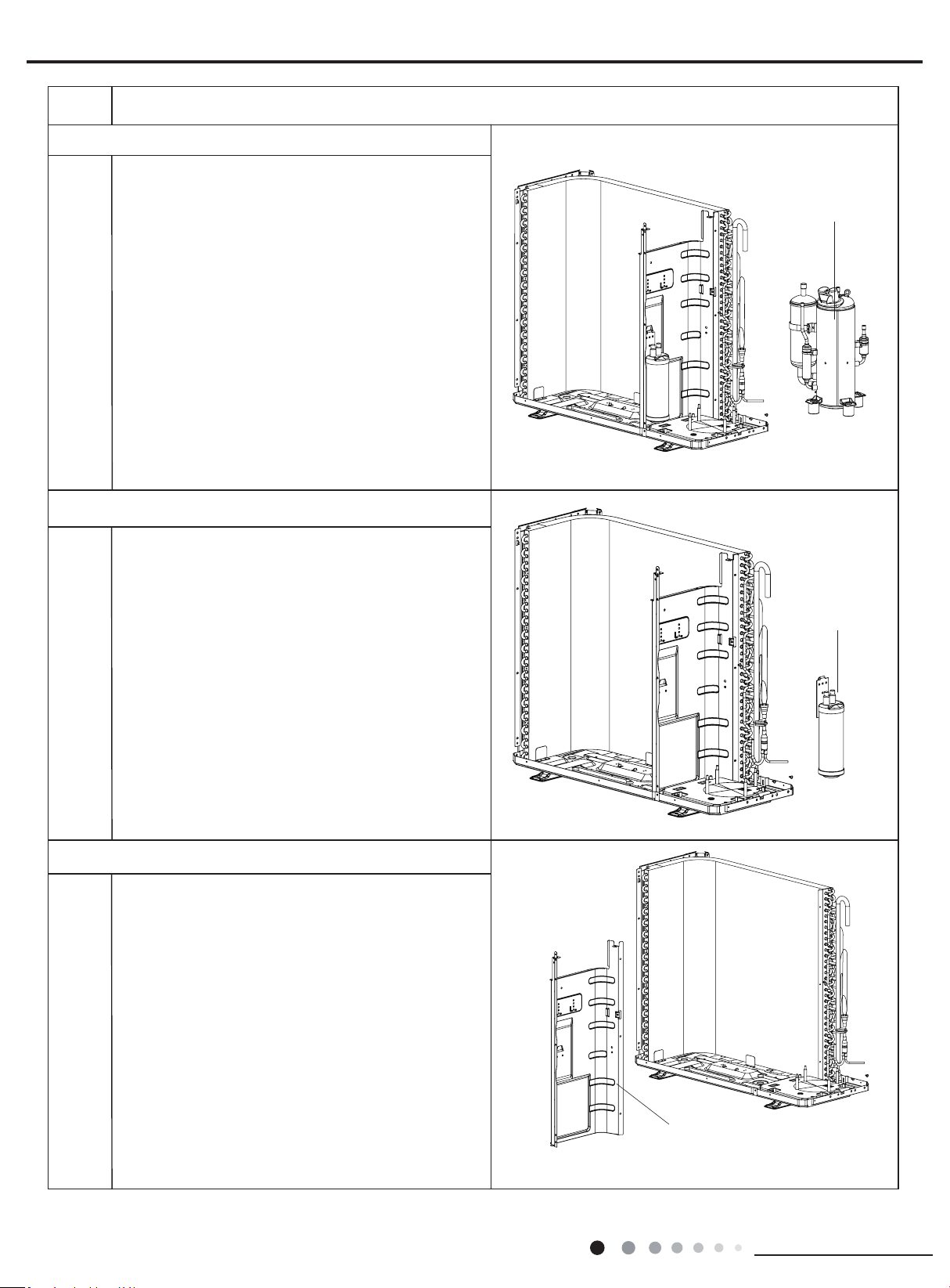
48
Installation and Maintenance
Service Manual
Steps Procedure
Remove screws connecting middle isolation sheet
and support plate of condenser, chassis, and then
remove the middle isolation sheet.
13. Remove compressor
compressor
Remove the 3 foot nuts xing compressor and then lift
the compressor upwards to remove the compressor
and damping cushion.
Note:
Keep the ports of discharge pipe and suction pipe from
foreign objects.
15. Remove middle isolation sheet
14.Remove vapour liquid separator
Unsolder spot welds connected with vapour liquid
separator, remove 2 foot nuts fixing vapour liquid
separator and compressor mounting plate sub-assy, and
then remove the vapour liquid separator.
vapour liquid
separator
middle isolation
sheet
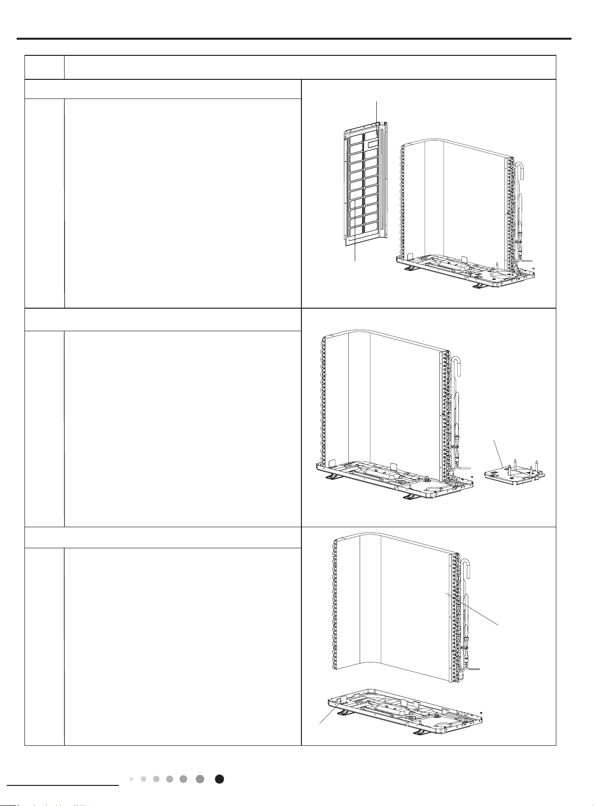
49
Installation and Maintenance
Service Manual
Steps Procedure
16.Remove left side plate
Remove screws connecting left side plate and
support plate of condenser, chassis, and then
remove the left side plate.
left side plate
support plate of condenser
17.Remove compressor mounting plate sub-assy
Remove the 4 foot nuts xing compressor mounting
plate sub-assy and chassis, to remove the
compressor mounting plate sub-assy.
compressor mounting
plate sub-assy
condenser
chassis
Pull it upwards to separate the chassis and condenser.
18. Remove condenser
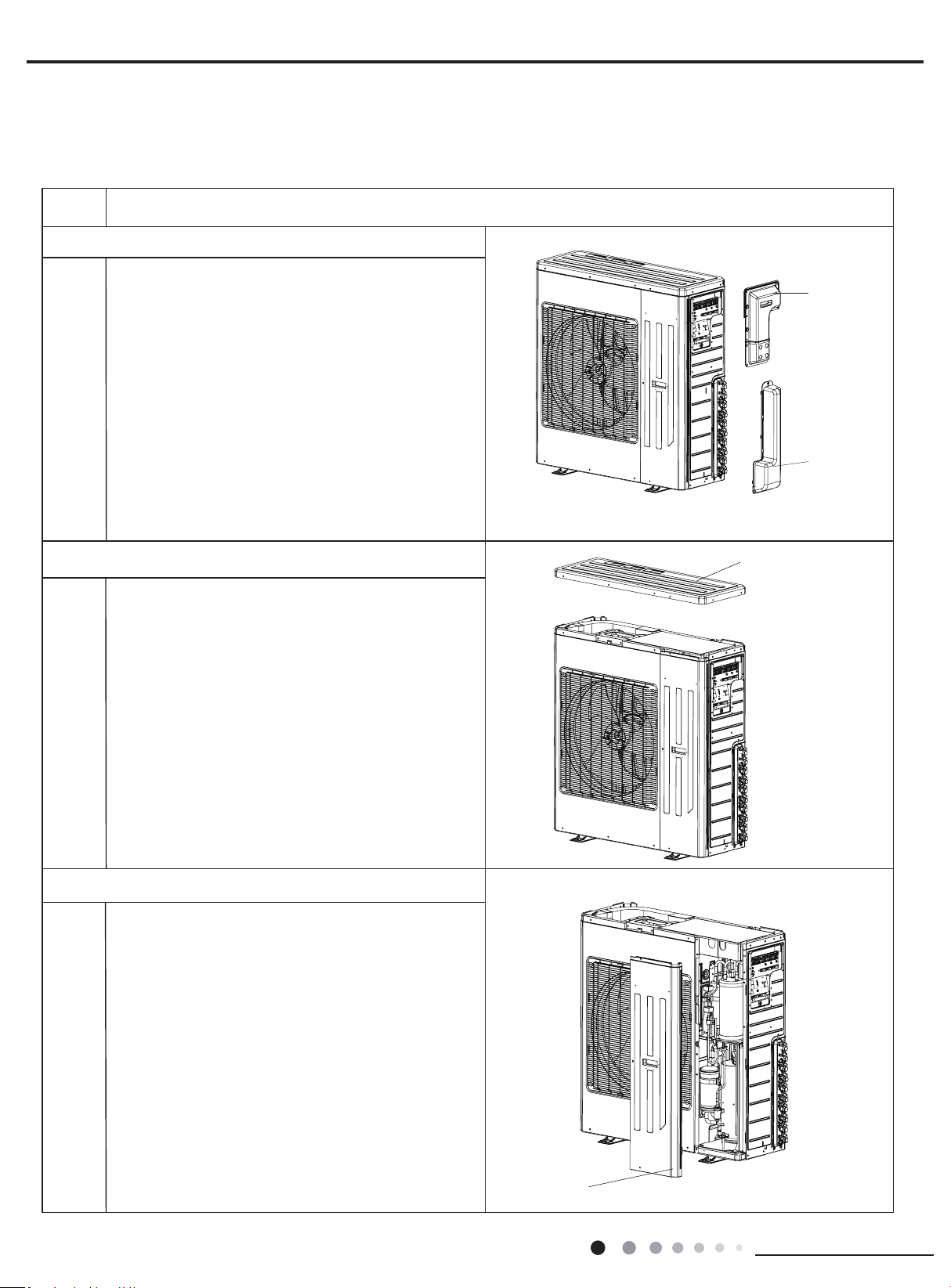
50
Installation and Maintenance
Service Manual
Steps Procedure
top cover
Remove the screws connecting the top cover with
outer case, right side plate and left side plate; lift the
top cover upwards to remove it.
1. Remove the handle and valve cover
2. Remove top cover
3.Remove front side plate
front side plate
Remove the screws connecting the front side plate
with chassis and middle isolation sheet,and then
remove the front side plate
MULTIU36HP230V1DO
MULTIU42HP230V1DO
handle
valve cover
Remove the screws connicting the handle with right
side plate and then remove the handle and valve
cover.
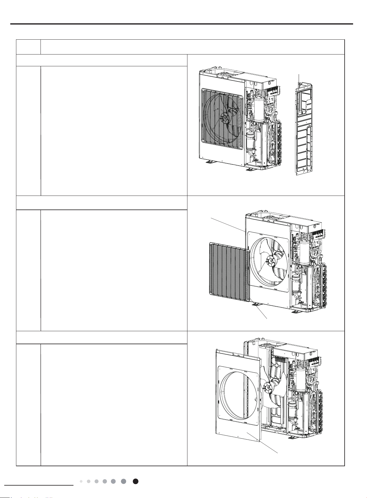
51
Installation and Maintenance
Service Manual
Steps Procedure
grille
right side plate
Remove the screws connecting the right side plate
with electric box assy, valve support, chassis and
condenser side plate, and then remove the right
side plate.
Remove the 4 screws connecting the grille and
outer case, and then remove the panel grille.
5.Remove right side plate
6.Remove grille and cabinet
cabinet
outer case
Remove screws connecting outer case and motor
support, middle isolation sheet and chassis, pull the
outer case upwards slightly, loosen clasps between
outer case and right side plate, left side plate, and
then remove the outer case.
7. Remove outer case
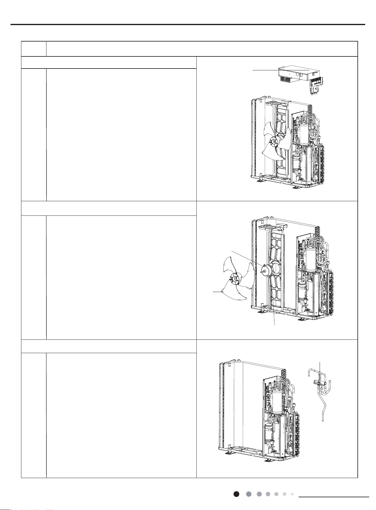
52
Installation and Maintenance
Service Manual
Steps Procedure
blade
motor support
motor
electric box assy
1.Remove the grounding wire screw on the electric
box assy and then remove the grounding wire.
2.Disconnect the wiring terminals of reactor,
compressor, high and low pressure switch,
compressor overload protector, temperature sensor,
outdoor fan motor and 4-way valve. (See g 2)
Note: keep pressing the circlip when disconnecting
the wiring terminal of reactor; keep pressing the
retainer when disconnecting other wiring terminals.
3.Remove the wire inside the wiring groove.
8. Remove electric box assy
9. Remove blade, motor, motor support, reactor
1.Remove nuts xing axial ow blade with wrench,
and then remove the axial ow blade.
2.Remove 2 screws connecting motor support and
chassis, loosen damper block and then remove the
motor support.
3.Remove 4 screws fixing motor,and then remove
the motor
4.Remove 4 screws fixing reactor sub-assy and
motor support, and then remove the reactor sub-
assy.
Unsolder the spot weld between 4-way valve and
vapour liquid separator, compressor cut-off valve
sub-assy and condenser, and then remove the 4-way
valve.
Note: When unsoldering the spot weld, wrap the
4-way valve with wet cloth completely to avoid
damage to valve due to high temperature.
10 Remove 4-way valve
4-way valve
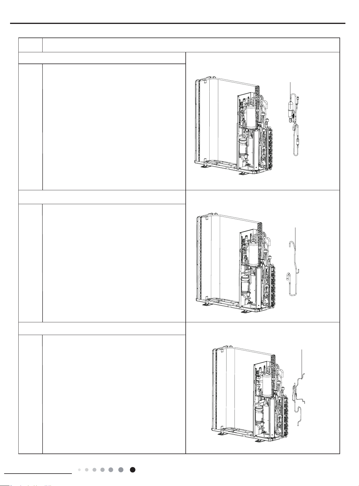
53
Installation and Maintenance
Service Manual
Steps Procedure
inhalation tube sub-
assy
oil separator sub-assy
Unsolder all spot welds oil separator sub-assy and
then remove the oil separator sub-assy.
Note:When unsoldering the spot weld, wrap the gas
valve and liquid valve with wet cloth completely to
avoid damage to valve due to high temperature.
Remove all spot welds inhalation tube sub-assy, and
then remove the inhalation tube sub-assy.
Remove all spot welds electromagnetic valve sub-
assy and then remove the electromagnetic valve sub-
assy.
11. Remove oil separator sub-assy
12. Remove
inhalation tube sub-assy
electromagnetic
valve sub-assy
13. Remove electromagnetic valve sub-assy
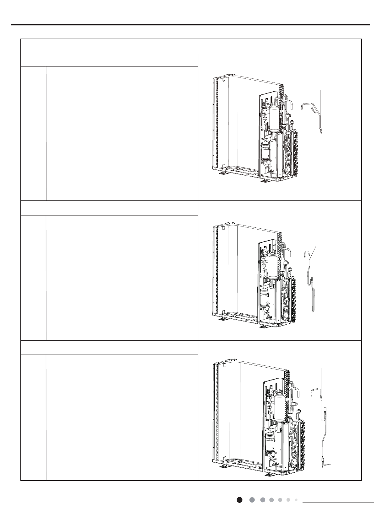
54
Installation and Maintenance
Service Manual
Steps Procedure
14.Remove connection pipe sub-assy
electric expansion
valve sub-assy
16. Remove
electric expansion valve sub-assy
15.Remove electromagnetic valve sub-assy
connection pipe sub-assy
electromagnetic valve
sub-assy
Remove all spot welds
connection pipe sub-assy
and
then remove the
connection pipe sub-assy
.
Remove all spot welds
electromagnetic valve sub-assy
and then remove the
electromagnetic valve sub-assy
.
Remove all spot welds
electric expansion valve sub-
assy
and then remove the
electric expansion valve sub-
assy
.
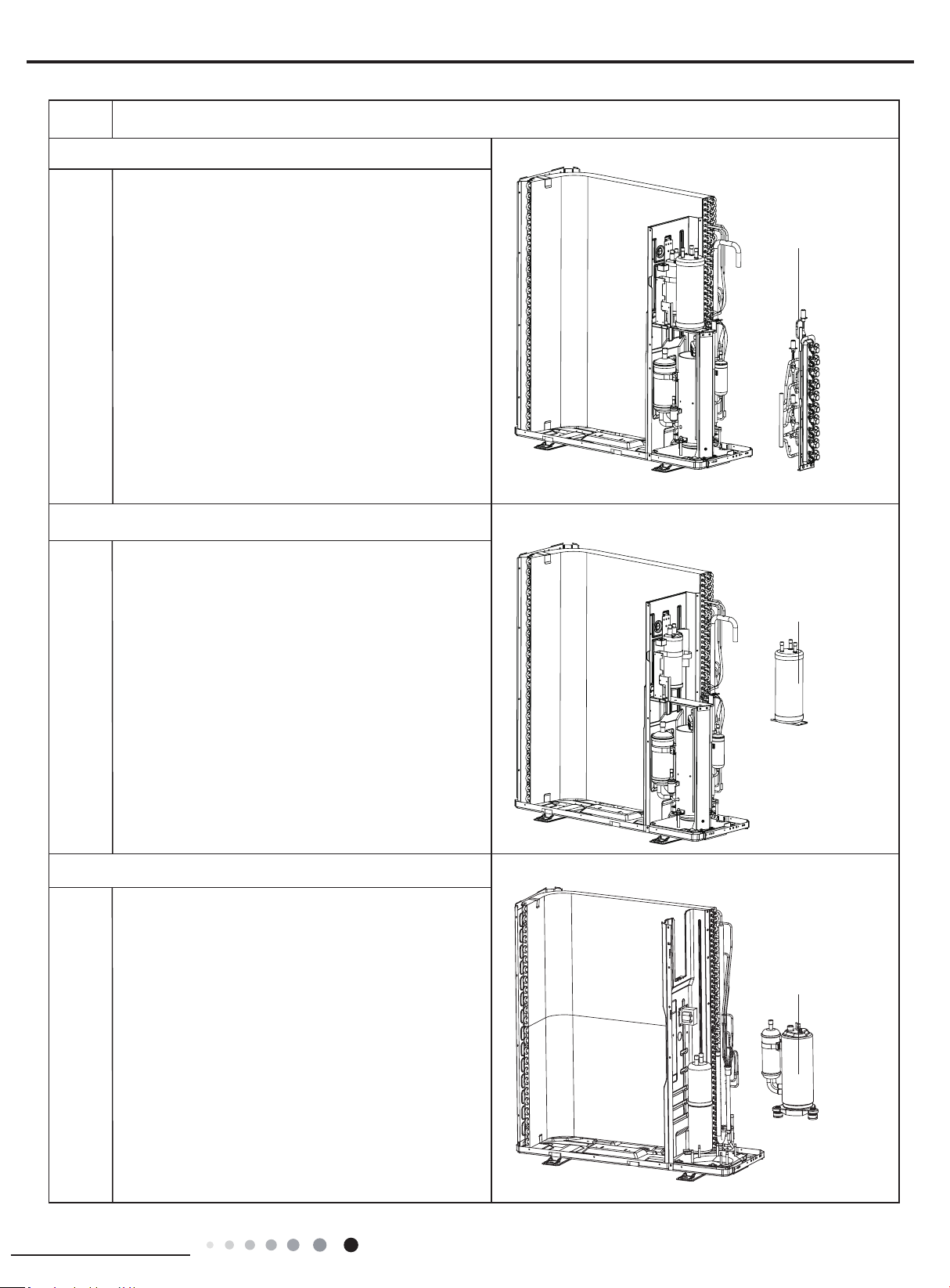
55
Installation and Maintenance
Service Manual
Steps Procedure
accumulator
valve support
Unsolder all spot welds connected with valve support
and then remove the valve support.
Note:When unsoldering the spot weld, wrap the gas
valve and liquid valve with wet cloth completely to
avoid damage to valve due to high temperature.
17. Remove valve support
18. Remove accumulator
gas-liquid
separator
19. Remove gas-liquid separator
Remove the screws connecting the gas-liquid
separator and remove the gas-liquid separator.
Remove the screws connecting the accumulator and
remove the accumulator.
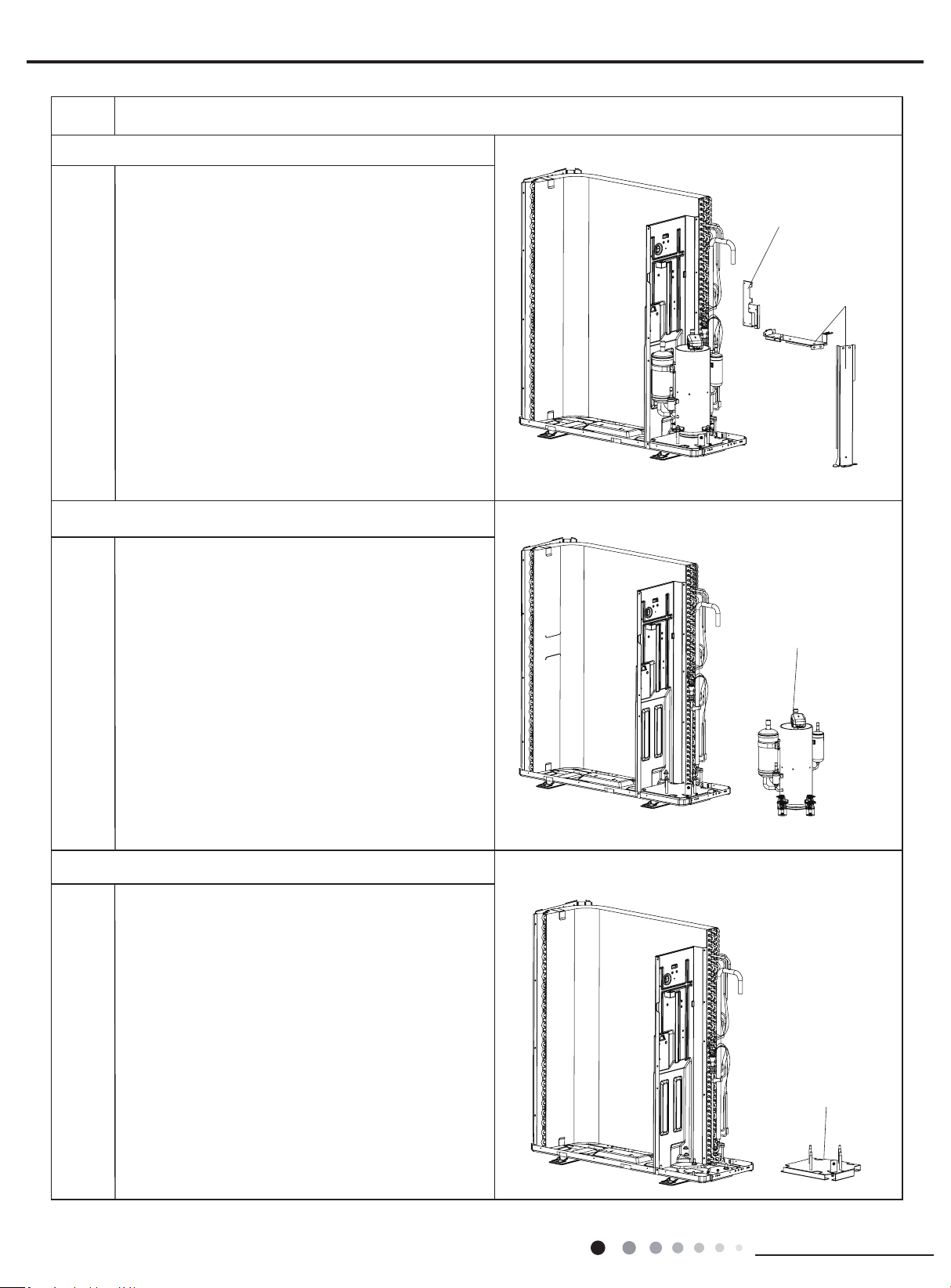
56
Installation and Maintenance
Service Manual
Steps Procedure
20.Remove supporting board and supporting board sub-assy
supporting
board sub-assy
supporting board
Remove the screws connecting the gsupporting
board and supporting board sub-assy and remove the
gsupporting board and supporting board sub-assy.
compressor
21. Remove compressor
Remove the 3 foot nuts xing compressor and then lift
the compressor upwards to remove the compressor
and damping cushion.
Note:
Keep the ports of discharge pipe and suction pipe from
foreign objects.
22.Remove compressor mounting plate sub-assy
Remove the 4 foot nuts fixing compressor mounting
plate sub-assy and chassis, to remove the compressor
mounting plate sub-assy.
compressor mounting
plate sub-assy
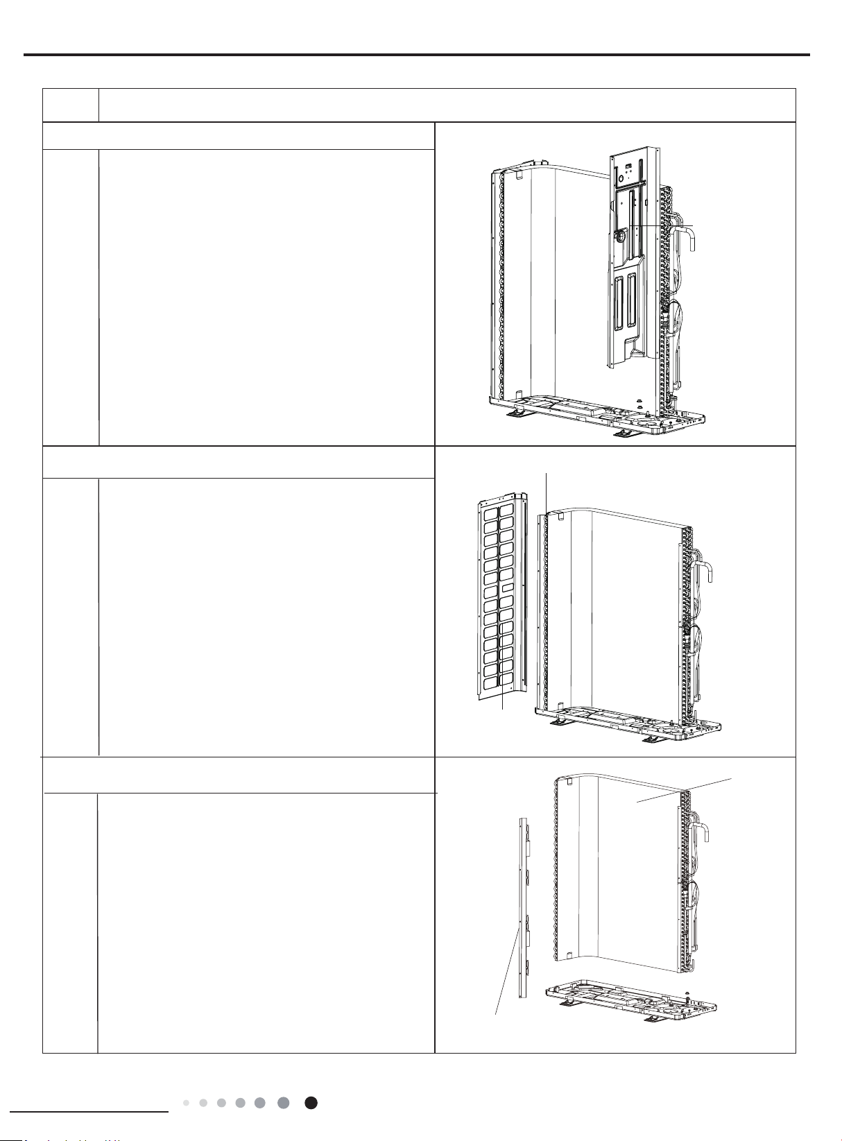
57
Installation and Maintenance
Service Manual
Steps Procedure
support plate of condenser
condenser
Remove 5 screws connecting condenser and chassis,
and then remove the condenser. Remove 2 screws
connecting support plate of condenser and condenser,
and then remove the support plate of condenser.
24.Remove left side plate
25. Remove condenser
Remove screws connecting left side plate and
support plate of condenser, chassis, and then
remove the left side plate.
left side plate
support plate of condenser
middle isolation
sheet
Remove screws connecting middle isolation sheet
and support plate of condenser, chassis, and then
remove the middle isolation sheet.
23. Remove middle isolation sheet
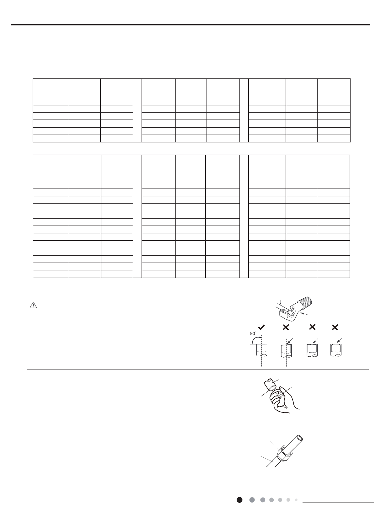
58
Installation and Maintenance
Service Manual
Appendix:
Appendix 1: Reference Sheet of Celsius and Fahrenheit
Set temperature
Conversion formula for Fahrenheit degree and Celsius degree: Tf=Tcx1.8+32
Ambient temperature
Fahrenheit
display
temperature
(℉)
Fahrenheit
(℉)
Celsius
(℃)
Fahrenheit
display
temperature
(℉)
Fahrenheit
(℉)
Celsius
(℃)
Fahrenheit
display
temperature
(℉)
Fahrenheit
(℉)
Celsius
(℃)
32/33 32 0 55/56 55.4 13 79/80 78.8 26
34/35 33.8 1 57/58 57.2 14 81 80.6 27
36 35.6 2 59/60 59 15 82/83 82.4 28
37/38 37.4 3 61/62 60.8 16 84/85 84.2 29
39/40 39.2 4 63 62.6 17 86/87 86 30
41/42 41 5 64/65 64.4 18 88/89 87.8 31
43/44 42.8 6 66/67 66.2 19 90 89.6 32
45 44.6 7 68/69 68 20 91/92 91.4 33
46/47 46.4 8 70/71 69.8 21 93/94 93.2 34
48/49 48.2 9 72 71.6 22 95/96 95 35
50/51 50 10 73/74 73.4 23 97/98 96.8 36
52/53 51.8 11 75/76 75.2 24 99 98.6 37
54 53.6
12 77/78 77 25
Fahrenheit
display
temperature
(℉)
Fahrenheit
(℉)
Celsius
(℃)
Fahrenheit
display
temperature
(℉)
Fahrenheit
(℉)
Celsius
(℃)
Fahrenheit
display
temperature
(℉)
Fahrenheit
(℉)
Celsius
(℃)
61 60.8 16 69/70 69.8 21 78/79 78.8 26
62/63 62.6 17 71/72 71.6 22 80/81 80.6 27
64/65 64.4 18 73/74 73.4 23 82/83 82.4 28
66/67 66.2 19 75/76 75.2 24 84/85 84.2 29
68 68 20 77 77 25 86 86 30
Downwards
Pipe
Shaper
Union pipe
Pipe
Pipe
Pipe cutter
Leaning Uneven Burr
Improper pipe expanding is the main cause of refrigerant leakage.Please
expand the pipe according to the following steps:
A:Cut the pip
● Conrm the pipe length according to the distance of indoor unit and outdoor unit.
● Cut the required pipe with pipe cutter.
B:Remove the burrs
● Remove the burrs with shaper and prevent the burrs from getting into the pipe.
C:Put on suitable insulating pipe
D:Put on the union nut
● Remove the union nut on the indoor connection pipe and outdoor valve; install
the union nut on the pipe.
E:Expand the port
● Expand the port with expander.
Appendix 2: Pipe Expanding Method
Note:
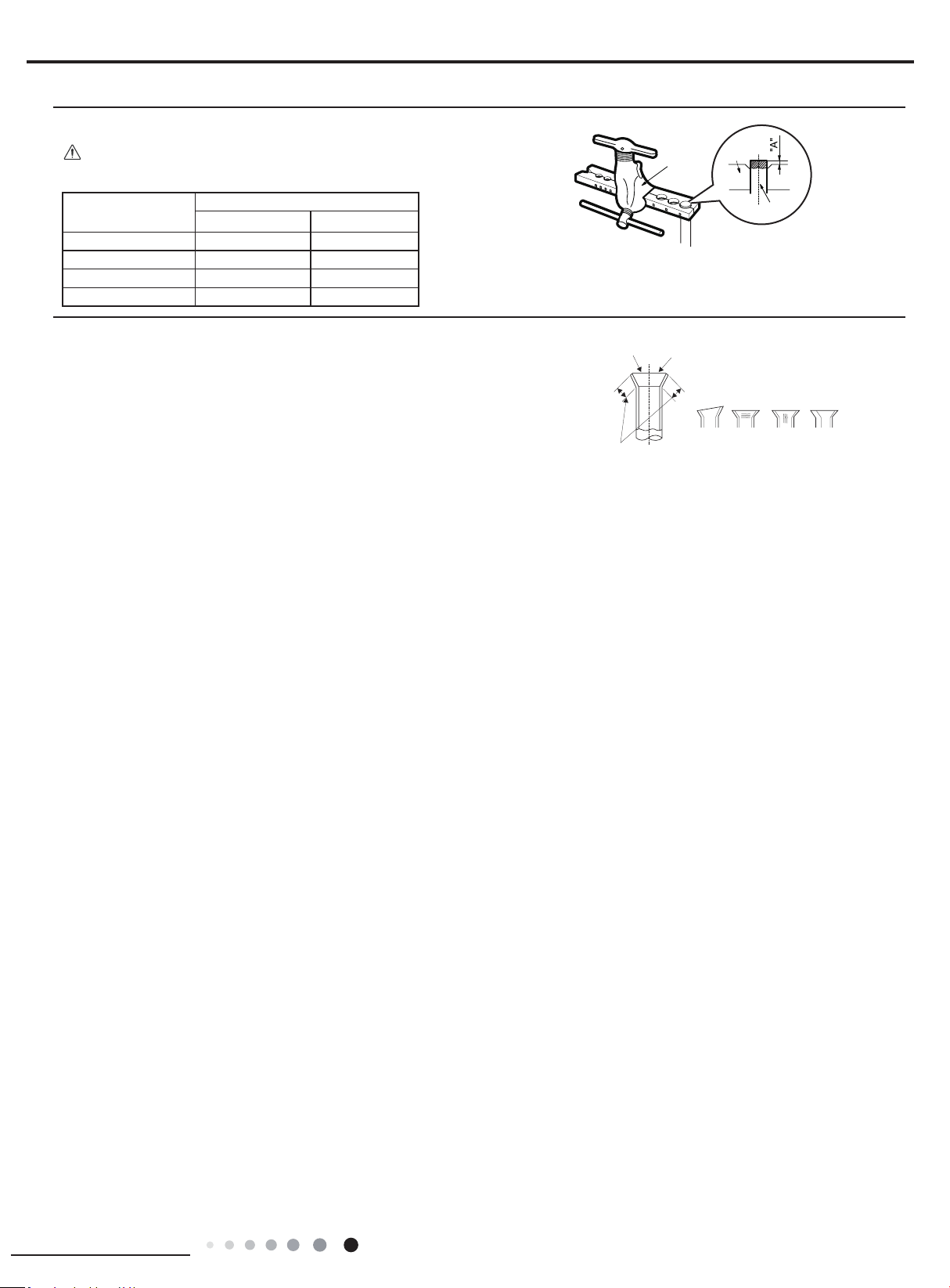
59
Installation and Maintenance
Service Manual
F:Inspection
● Check the quality of expanding port. If there is any blemish, expand the
port again according to the steps above.
The length is equal
Improper expanding
leaning
damaged
surface
crack uneven
thicknes
s
Smooth surface
Expander
Hard
mold
Pipe
● "A" is different according to the diameter, please refer to the sheet below:
Outer
diameter(inch)
A(inch)
Max Min
Ф0.23 - 0.25 (1/4") 0.051 0.028
Ф9.52 (3/8”) 0.063 0.039
Ф0.37 - 0.5 (1/2”) 0.071 0.039
Ф0.63 (5/8”) 0.095 0.087
Note:
60
Installation and Maintenance
Service Manual
Appendix 3: List of Resistance for Temperature Sensor
Resistance Table of Ambient Temperature Sensor for Indoor and Outdoor(15K)
Temp(
o
C) Resistance(kΩ) Temp(
o
C) Resistance(kΩ) Temp(
o
C) Resistance(kΩ) Temp(
o
C) Resistance(kΩ)
-19 138.1 20 18.75 59 3.848 98 1.071
-18 128.6 21 17.93 60 3.711 99 1.039
-17 121.6 22 17.14 61 3.579 100 1.009
-16 115 23 16.39 62 3.454 101 0.98
-15 108.7 24 15.68 63 3.333 102 0.952
-14 102.9 25 15 64 3.217 103 0.925
-13 97.4 26 14.36 65 3.105 104 0.898
-12 92.22 27 13.74 66 2.998 105 0.873
-11 87.35 28 13.16 67 2.896 106 0.848
-10 82.75 29 12.6 68 2.797 107 0.825
-9 78.43 30 12.07 69 2.702 108 0.802
-8 74.35 31 11.57 70 2.611 109 0.779
-7 70.5 32 11.09 71 2.523 110 0.758
-6 66.88 33 10.63 72 2.439 111 0.737
-5 63.46 34 10.2 73 2.358
112 0.717
-4 60.23 35 9.779 74 2.28 113 0.697
-3 57.18 36 9.382 75 2.206 114 0.678
-2 54.31 37 9.003 76 2.133 115 0.66
-1 51.59 38 8.642 77 2.064 116 0.642
0 49.02 39 8.297 78 1.997 117 0.625
1 46.6 40 7.967 79 1.933 118 0.608
2 44.31 41 7.653 80 1.871 119 0.592
3 42.14 42 7.352 81 1.811 120 0.577
4 40.09 43 7.065 82 1.754 121 0.561
5 38.15 44 6.791 83 1.699 122 0.547
6 36.32 45 6.529 84 1.645 123 0.532
7 34.58 46 6.278 85 1.594 124 0.519
8 32.94 47 6.038 86 1.544 125 0.505
9 31.38 48 5.809 87 1.497 126 0.492
10 29.9 49 5.589 88 1.451 127 0.48
11 28.51 50 5.379 89 1.408 128 0.467
12 27.18 51 5.197
90 1.363 129 0.456
13 25.92 52 4.986 91 1.322 130 0.444
14 24.73 53 4.802 92 1.282 131 0.433
15 23.6 54 4.625 93 1.244 132 0.422
16 22.53 55 4.456 94 1.207 133 0.412
17 21.51 56 4.294 95 1.171 134 0.401
18 20.54 57 4.139 96 1.136 135 0.391
19 19.63 58 3.99 97 1.103 136 0.382
61
Installation and Maintenance
Service Manual
Resistance Table of Tube Temperature Sensors for Indoor and Outdoor (20K)
Temp(
o
C) Resistance(kΩ) Temp(
o
C) Resistance(kΩ) Temp(
o
C) Resistance(kΩ) Temp(
o
C) Resistance(kΩ)
-19 181.4 20 25.01 59 5.13 98 1.427
-18 171.4 21 23.9 60 4.948 99 1.386
-17 162.1 22 22.85 61 4.773 100 1.346
-16 153.3 23 21.85 62 4.605 101 1.307
-15 145 24 20.9 63 4.443 102 1.269
-14 137.2 25 20 64 4.289 103 1.233
-13 129.9 26 19.14 65 4.14 104 1.198
-12 123 27 18.13 66 3.998 105 1.164
-11 116.5 28 17.55 67 3.861 106 1.131
-10 110.3 29 16.8 68 3.729 107 1.099
-9 104.6 30 16.1 69 3.603 108 1.069
-8 99.13 31 15.43 70 3.481 109 1.039
-7 94 32 14.79 71 3.364 110 1.01
-6 89.17 33 14.18 72 3.252 111 0.983
-5 84.61 34 13.59 73 3.144 112 0.956
-4 80.31 35 13.04 74 3.04 113 0.93
-3 76.24 36 12.51 75 2.94 114 0.904
-2 72.41 37 12 76 2.844 115 0.88
-1 68.79 38 11.52 77 2.752 116 0.856
0 65.37 39 11.06 78 2.663 117 0.833
1 62.13 40 10.62 79 2.577 118 0.811
2 59.08 41 10.2 80 2.495 119 0.77
3 56.19 42 9.803 81 2.415 120 0.769
4 53.46 43 9.42 82 2.339 121 0.746
5 50.87 44 9.054 83 2.265 122 0.729
6 48.42 45 8.705 84 2.194 123 0.71
7 46.11 46 8.37 85 2.125 124 0.692
8 43.92 47 8.051 86 2.059 125 0.674
9 41.84 48 7.745 87 1.996 126 0.658
10 39.87 49 7.453 88 1.934 127 0.64
11 38.01 50 7.173 89 1.875 128 0.623
12 36.24 51 6.905 90 1.818 129 0.607
13 34.57 52 6.648 91 1.736 130 0.592
14 32.98 53 6.403 92 1.71 131 0.577
15 31.47 54 6.167 93 1.658 132 0.563
16 30.04 55 5.942 94 1.609 133 0.549
17 28.68 56 5.726 95 1.561 134 0.535
18 27.39 57 5.519 96 1.515 135 0.521
19 26.17 58 5.32 97 1.47 136 0.509
62
Installation and Maintenance
Service Manual
Resistance Table of Discharge Temperature Sensor for Outdoor(50K)
Temp(
o
C) Resistance(kΩ) Temp(
o
C) Resistance(kΩ) Temp(
o
C) Resistance(kΩ) Temp(
o
C) Resistance(kΩ)
-29 853.5 10 98 49 18.34 88 4.75
-28 799.8 11 93.42 50 17.65 89 4.61
-27 750 12 89.07 51 16.99 90 4.47
-26 703.8 13 84.95 52 16.36 91 4.33
-25 660.8 14 81.05 53 15.75 92 4.20
-24 620.8 15 77.35 54 15.17 93 4.08
-23 580.6 16 73.83 55 14.62 94 3.96
-22 548.9 17 70.5 56 14.09 95 3.84
-21 516.6 18 67.34 57 13.58 96 3.73
-20 486.5 19 64.33 58 13.09 97 3.62
-19 458.3 20 61.48 59 12.62 98 3.51
-18 432 21 58.77 60 12.17 99 3.41
-17 407.4 22 56.19 61 11.74 100 3.32
-16 384.5 23 53.74 62 11.32 101 3.22
-15 362.9 24 51.41 63 10.93
102 3.13
-14 342.8 25 49.19 64 10.54 103 3.04
-13 323.9 26 47.08 65 10.18 104 2.96
-12 306.2 27 45.07 66 9.83 105 2.87
-11 289.6 28 43.16 67 9.49 106 2.79
-10 274 29 41.34 68 9.17 107 2.72
-9 259.3 30 39.61 69 8.85 108 2.64
-8 245.6 31 37.96 70 8.56 109 2.57
-7 232.6 32 36.38 71 8.27 110 2.50
-6 220.5 33 34.88 72 7.99 111 2.43
-5 209 34 33.45 73 7.73 112 2.37
-4 198.3 35 32.09 74 7.47 113 2.30
-3 199.1 36 30.79 75 7.22 114 2.24
-2 178.5 37 29.54 76 7.00 115 2.18
-1 169.5 38 28.36 77 6.76 116 2.12
0 161 39 27.23 78 6.54 117 2.07
1 153 40 26.15 79 6.33 118 2.02
2 145.4 41 25.11
80 6.13 119 1.96
3 138.3 42 24.13 81 5.93 120 1.91
4 131.5 43 23.19 82 5.75 121 1.86
5 125.1 44 22.29 83 5.57 122 1.82
6 119.1 45 21.43 84 5.39 123 1.77
7 113.4 46 20.6 85 5.22 124 1.73
8 108 47 19.81 86 5.06 125 1.68
9 102.8 48 19.06 87 4.90 126 1.64
JF00304118
GREE ELECTRIC APPLIANCES, INC. OF ZHUHAI
Add: West Jinji Rd, Qianshan, Zhuhai,Guangdong, China, 519070
Tel: (+86-756) 8522218
Fax: (+86-756) 8669426
E-mail: [email protected] www.gree.com
HONG KONG GREE ELECTRIC APPLIANCES SALES LIMITED
Add: Unit 2612,26/F.,Miramar Tower 132 Nathan Road,TST,Kowloon,HK
Tel: (852) 31658898 Fax: (852) 31651029
For product improvement, specifications and appearance in this manual are subject to change without prior notice.
Cat No: GREE_MULTIU_SERVICE & PARTS_18-42MBH_082919