Loading ...
Loading ...
Loading ...
.
Carefullyremovethe hexnut and washerwhichsecuresthehex
shaftto the snowthrowerframeand lightlytap the shaft'send _;!
to dislodgethe ball bearingfromthe rightsideof the frame.See
Figure35. .]_j
NOTE:Becarefulnot to damagethe threadson the shaft.
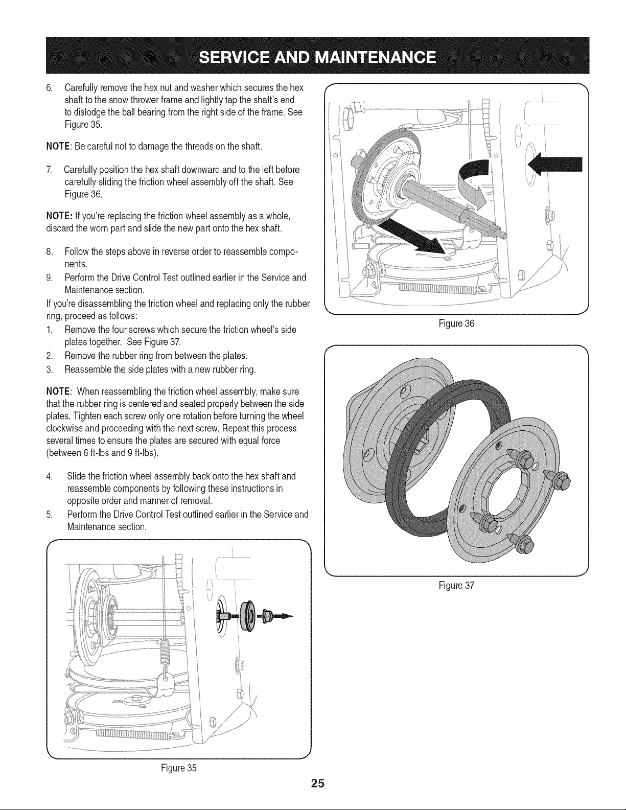
7. Carefullypositionthe hexshaftdownwardand to the left before
carefullyslidingthe frictionwheelassemblyoff the shaft.See
Figure36.
NOTE: Ifyou'rereplacingthe frictionwheelassemblyas a whole,
discardthe wornpartand slidethe newpart ontothe hexshaft.
8. Followthe stepsabovein reverseorderto reassemblecompo-
nents.
9. Performthe DriveControlTestoutlinedearlier inthe Serviceand
Maintenancesection.
If you'redisassemblingthefrictionwheeland replacingonly the rubber
ring,proceedas follows:
1. Removethefour screwswhich securethe frictionwheel'sside
platestogether. SeeFigure37.
2. Removethe rubberringfrom betweenthe plates.
3. Reassemblethe side plateswith a newrubberring.
Figure36
NOTE: Whenreassemblingthe frictionwheelassembly,makesure
thatthe rubberring is centeredand seatedproperlybetweenthe side
plates.Tighteneachscrewonlyone rotationbeforeturningthe wheel
clockwiseand proceedingwith the nextscrew.Repeatthis process
severaltimes toensurethe platesaresecuredwith equalforce
(between6 ft-lbsand 9 ft-lbs).
4. Slide the frictionwheelassemblybackonto the hexshaftand
reassemblecomponentsby followingthese instructionsin
oppositeorderand mannerof removal.
5. Performthe DriveControlTestoutlinedearlierin the Serviceand
Maintenancesection.
f
Figure35
Figure37
J
Loading ...
Loading ...
Loading ...