1-800-243-0000
24 HOURS A DAY, 7 DAYS A WEEK FOR LG CUSTOMER SERVICE
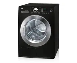
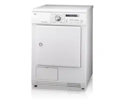
ElectricandGasDryer
DLE3733W / DLG3744W
DLE3733S / DLG3744S
LG
as it provides instructions
iiiiiiiiiiiiiiiiiiiiiiiiiiiiiiiiiiiiiiiiiiiiiiiiiiiiiiiiiiiiiiiiiiiiiiii!_!!F
fifififififififififififififififififi_i_il_
iiiiiiiiiiiiiiiiiiiiiiiiiiiiiiiiiiiiij_
iiiiiiiiiiiiiiiiiiiiiiiiiiiiiiiiiiii_,
iiiiiiiiiiiiiiiiiiiiiiiiiiiiiiiiiiiiiiiii_,
iiiiiiiiiiiiiiiiiiiiiiiiiiiiiiiiiiiiiiiiiiiiiii_.....
reference.
at http://us.lge.com
iiiiiiiiiiiiiiiiiiiiiiiiiiiiiiiiiiiiiiiiiiiii_.........
iiiiiiiiiiiiiiiiiiiiiiiiiiiiiiiiiiiiiiiiiiiiiiiiiiiiiiiiiiiiiiiiiiiiiiiiii_...........
P/No.: 3828EL3004J
OUTSTANDING PERFORMANCE
Not to mention unmatched big capacity, you can benefit from good
time efficiency, quiet operation and energy saving system.
DOUBLE-COATED STEELDRUM
It is coated with one metal coating and the other polymer coating in order to guarantee high
durability and the long life.
ARTISTIC DESIGN
Modern front panel look and big crystal-clear glass door make your house look stylish.
DIGITAL FABRICCARE
Multi-level temperature control heater takes a better care on your valued clothes.
EASY OF USE
A whole selection of user-friendly functions always make you comfortable with dryer operation.
Your dryer provides sensor drying and time drying programs.
Sensor Dry
The dryer senses the dampness of the laundry and automatically determines the heat level and operation time. You might
see a sudden increase or decrease in operation time if the sensor determines more or less drying is required. This is not a
malfunction.
Time Dry
Use TIME DRY to select heat level and drying time manually. This can be used if clothes are not as dry as you like them
at the end of the cycle. Use TIME DRY for heavy and bulky items and thick work.
PART 1. SPECIFICATIONS ................................................................................................................................................................................................................. 3
PART 2. iMPORTANT WARRANTY AND SAFETY iNSTRUCTiONS ............................................................................................................................................... 4
PART 3. INmAL STEPS FOR iNSTALLING YOUR DRYER ............................................................................................................................................................ 11
PART 4. ACCESSORIES INSTALLATION ........................................................................................................................................................................................ 17
PART 5. ELECTRICAL REQUIREMENTS FOR ELECTRIC DRYERS .............................................................................................................................................. 19
PART 6. ELECTRICAL REQUIREMENTS FOR GAS DRYERS ......................................................................................................................................................... 23
PART 7. GAS REQUIREMENTS AND INSTRUCTIONS .................................................................................................................................................................... 24
PART 8. EXHAUST REQUIREMENTS AND MAINTENANCE ........................................................................................................................................................... 25
PART 9. OPERATING YOUR DRYER ................................................................................................................................................................................................ 27
PART 10. TROUBLESHOOTING GUIDE ............................................................................................................................................................................................ 33
LG DRYER LIMITED WARRANTY ...................................................................................................................................................................................................... 36
2

m Type : Electric and Gas Dryer
m Rating : Please refer to the rating label regarding detailed information.
m Size : 27 x 29.9 x 38.7(inch)
m Capacity : IEC 7.3 cu.ft. (22.5 Ib)
m Weight : 126 Ibs (57.2 kg)
÷ Specifications are subject to change by manufacturer.
,--m ACCESSORIES
Dryer Rack
Purchased Separately
Stacking Kit
Purchased Separately
:_ l)es_gn of pedesmL_ i,_ sul_ject to
change widtout manafatttrers notice.
Pedestal
Purchased Separately
See page 28,[br instructions. See page I5,[br instructions. Seepage I6 ,[br instructions.
J
3
SEEKINGWARRANTYSERVICE
The warranty for your dryer is located at the end of this manual. Warranty Service is
available by contacting your nearest LG Service Center. If this product is installed and
operated according to the instructions in this manual, LG will repair or replace any parts
defective in material or workmanship throughout the warranty period, beginning with the
date of purchase.
WARNING!
For your safety, the recommendations in this manual must be followed. To reduce the risk
of fire or explosion, electric shock or to prevent property damage, personal injury, or death
when using your appliance follow basic precautions.
Warranty Restriction: If the dryer is subjected to other than single family use, all warranty
coverage is effective for only 90 days.
You will need the complete model and serial number when requesting warranty service, proof of
purchase date is required.
Use the space below to record the model number and serial number of your new LG dryer.
Model Number.
Serial Number.
Date of Purchase
_I_ Staple your receipt here for convenience when contacting service.
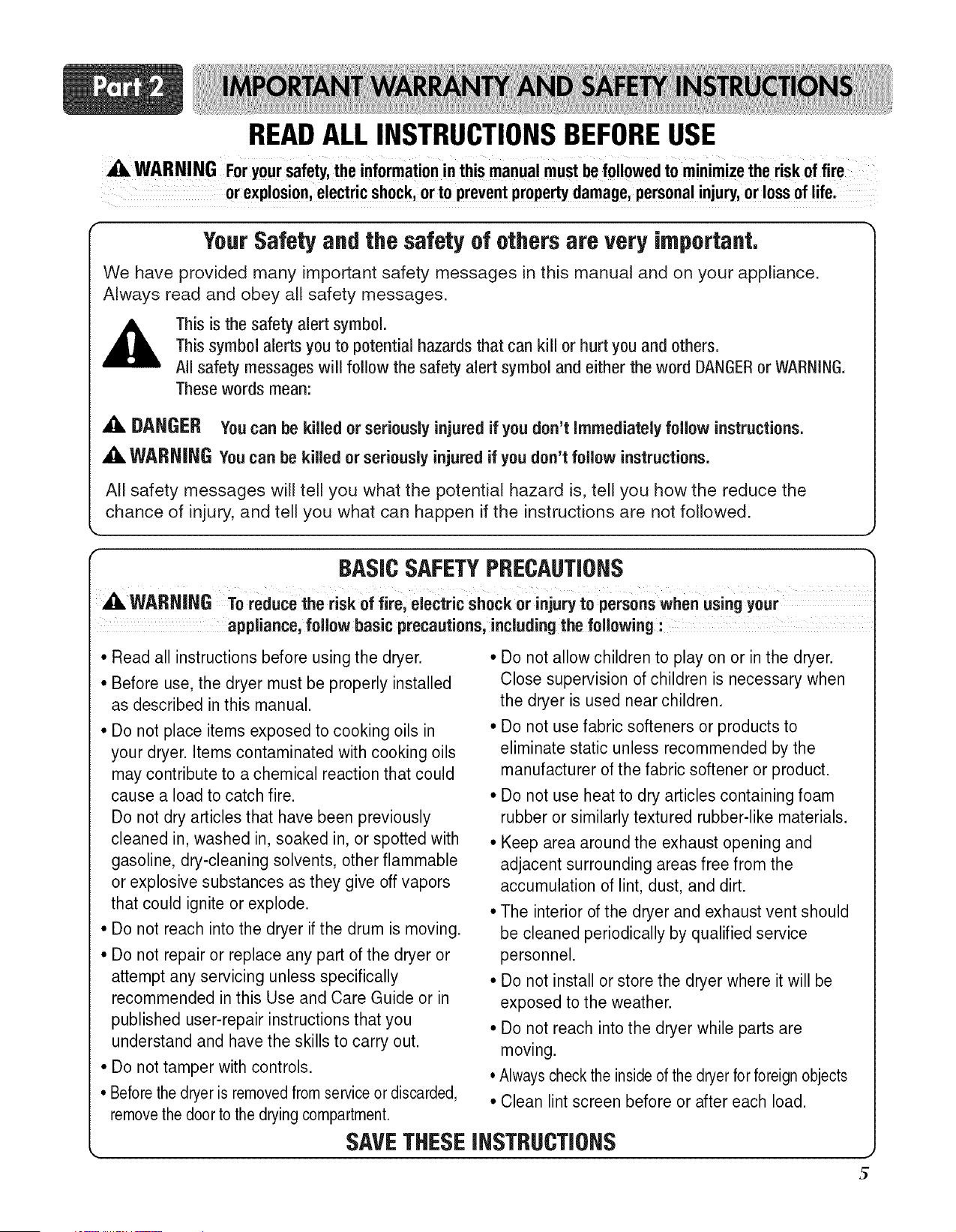
READALLINSTRUCTIONSBEFOREUSE
WARNING For yoursafety,the informationinthis manualmustbefollowedto minimizethe riskof fire
or explosion,electricshock,orto preventpropertydamage,personalinjury,or lossof life.
Your Safety and the safety of others are very important,
We have provided many important safety messages in this manual and on your appliance.
Always read and obey all safety messages.
This is the safety alert symbol.
This symbol alerts you to potential hazards that can kill or hurt you and others.
All safety messages will follow the safety alert symbol and either the word DANGERor WARNING.
These words mean:
A DANGER You can be killed or seriously injured if you don't Immediately follow instructions.
,A WARNING You can be killed or seriously injured if you don't follow instructions.
All safety messages will tell you what the potential hazard is, tell you how the reduce the
chance of injury, and tell you what can happen if the instructions are not followed.
r BASICSAFETYPRECAUTIONS
A WARNING
To reduce the risk of fire, electric shock or injury to persons when using your
appliance, follow basic precautions, including the following :
• Read all instructions before using the dryer.
• Before use, the dryer must be properly installed
as described in this manual.
• Do not place items exposed to cooking oils in
your dryer. Items contaminated with cooking oils
may contribute to a chemical reaction that could
cause a load to catch fire.
Do not dry articles that have been previously
cleaned in, washed in, soaked in, or spotted with
gasoline, dry-cleaning solvents, other flammable
or explosive substances as they give off vapors
that could ignite or explode.
• Do not reach into the dryer if the drum is moving.
• Do not repair or replace any part of the dryer or
attempt any servicing unless specifically
recommended in this Use and Care Guide or in
published user-repair instructions that you
understand and have the skills to carry out.
• Do not tamper with controls.
• Beforethe dryer is removedfrom service or discarded,
removethe door to the drying compartment.
• Do not allow children to play on or in the dryer.
Close supervision of children is necessary when
the dryer is used near children.
• Do not use fabric softeners or products to
eliminate static unless recommended by the
manufacturer of the fabric softener or product.
• Do not use heat to dry articles containing foam
rubber or similarly textured rubber-like materials.
• Keep area around the exhaust opening and
adjacent surrounding areas free from the
accumulation of lint, dust, and dirt.
• The interior of the dryer and exhaust vent should
be cleaned periodically by qualified service
personnel.
• Do not install or store the dryer where it will be
exposed to the weather.
• Do not reach into the dryer while parts are
moving.
• Always checkthe insideof the dryer for foreign objects
• Clean lint screen before or after each load.
SAVETHESEINSTRUCTIONS
READALLINSTRUCTIONSBEFOREUSE
A WARNING For your safety, the information in this manual must be followed to minimize the risk of
fire or explosion, electric shock, orto prevent property damage, personal injury, or loss
of life.
• Do not store or use gasoline or other
flammable vapors and liquids in the vicinity
of this appliance or any other appliance.
• Installation and service must be performed
by a qualified installer, service agency, or
the gas supplier.
BASICSAFETYPRECAUTIONS
WARNING To reduce the risk of fire, electric shock or injury to persons when using your
appliance, follow basic precautions, including the following"
GROUNDING INSTRUCTIONS
This appliance must be grounded.
In the event of malfunction or breakdown,
grounding will reduce the risk of electric shock
by providing a path of least resistance for
electric current. This appliance must be
equipped with a cord having an equipment-
grounding conductor and a grounding plug.
The plug must be plugged into an appropriate
outlet that is properly installed and grounded
in accordance with all local codes and
ordinances.
WARNING - Improper connection of the
equipment- rounding conductor can result in a
risk of electric shock. Check with a qualified
electrician or service person if you are in doubt
as to whether the appliance is properly
grounded.
Do not modify the plug provided with the
appliance.
If it will not fit the outlet, have a proper outlet
installed by a qualified electrician.
This appliance must be connected to a
grounded metal, permanent wiring system or an
equipment-grounding conductor must be run
with the circuit conductors and connected to the
equipment-grounding terminal or lead on the
appliance.
5
READALLINSTRUCTIONSBEFOREUSE
fire or explosion, electric shock, orto prevent property damage, personal injury, or loss
of life.
WHATTO DOIF YOUSMELLGAS
1. Do not try to light a match or cigarette, or
turn on any gas or electrical appliance.
2. Do not touch any electrical switches.
Do not use any phone in your building.
3. Clear the room, building, or area of all
occupants.
4. Immediately call your gas supplier from a
neighbor's phone. Follow the gas supplier's
phone. Follow the gas supplier's
instructions carefully.
5. If you cannot reach your gas supplier, call
the fire department.
CALIFORNIASAFEDRINKINGWATERANDTOXICENFORCEMENTACT
This act requires the governor of California to publish a list of substances known to the state
to cause cancer, birth defects, or other reproductive harm and requires businesses to warn
customers of potential exposure to such substances.
Gas appliances can cause minor exposure to four of these substances, namely benzene,
carbon monxide, formaldehyde, and soot, caused primarily by the incomplete combustion of
natural gas or LP fuels.
Properly adjusted dryers will minimize incomplete combustion. Exposure to these substances
can be minimized further by properly venting the dryer to the outdoors.
7
READALLINSTRUCTIONSBEFOREUSE
X_ WARNING For your safety, the information in this manual must be followed to minimize the risk of
fire or explosion, electric shock, or to prevent property damage, personal injury, or loss
of life.
SAFETYINSTRUCTIONFORINSTALLATION
appliance, follow basic precautions,including the f0110wing:
• Properly ground dryer to conform with
all governing codes and ordinances.
Follow details in the installation
instructions.
Electrical shock can result if the dryer is not
properly grounded.
• Before use, the dryer must be properly
installed as described in this manual.
Electrical shock can result if the dryer is not
properly grounded.
• Install and store the dryer where it will
not be exposed to temperatures below
freezing or exposed to the weather.
All repairs and servicing must be performed
by an authorized servicer unless specifically
recommended in this Owner's Guide.
Use only authorized factory parts.
Failure to follow this warning can cause
serious injury,fire, electrical shock or death.
• Do not install the washer in humid
spaces to reduce the risk of electric
shock.
Failure to follow this warning can cause
serious injury,fire, electrical shock or death.
• Connect to a properly rated, protected,
and sized power circuit to avoid
electrical overload.
Improper power circuit can melt, creating
electrical shock and/or fire hazard.
• Remove all packing items and dispose
of all shipping materials properly.
Failure to do so can result in death,
explosion, fire or burns.
• Place dryer at least 18 in. above the floor
for a garage installation.
Failure to do so can result in death,
explosion, fire or burns.
8
READALLINSTRUCTIONSBEFOREUSE
WARNING Foryour safety, the information in this manual must be followed to minimize the risk of
of life.
SAFETYINSTRUCTIONFORINSTALLATION(cont,)
Exhaust/Ducting:
• Gas dryers MUST be exhausted to the
outside.
Failure to follow these instructions can result
in fire or death.
• The dryer exhaust system must be
exhausted to the outside of the dwelling.
The dryer is not exhausted outdoors, some
fine lint and large amounts of moisture will
be expelled into the laundry area. An
accumulation of lint in any area of the home
can create a health and fire hazard.
• Use only rigid metal or flexible metal 4in.
Diameter ductwork inside the dryer
cabinet or for exhausting to the outside.
Use of plastic or other combustible ductwork
can cause a fire. Punctured ductwork can
cause a fire if it collapses or becomes
otherwise restricted in use or during
installation.
• Ductwork is not provided with the dryer,
and you should obtain the necessary
ductwork locally. The end cap should
have hinged dampers to prevent back
draft when the dryer is not in use.
Failure to follow these instructions can resul
in fire or death.
The exhaust duct must be 4 in. (10 cm)
in diameter with no obstructions. The
exhaust duct should be kept as short as
possible. Make sure to clean any old
ducts before installing your new dryer.
Failure to follow these instructions can result
in fire or death.
• Rigid or semi rigid metal ducting is
recommended for use between the dryer
and the wall. In special installations when
it is impossible to make a connection
with the above recommendations, a UL-
listed flexible metal transition duct may
be used between the dryer and wall
connection only. The use of this ducting
will affect drying time.
Failure to follow these instructions can result
in fire or death.
DO NOT use sheet metal screws or other
fasteners which extend into the duct that
could catch lint and reduce the efficiency
of the exhaust system. Secure all joints
with duct tape. 'I]U For complete details,
follow the Installation Instructions.
Failure to follow these instructions can result
in fire or death.
9
READALLINSTRUCTIONSBEFOREUSE
A WARNING F0r y0ur safety, the information in this manual must be followed to minimize the risk of
fire or explosion,electric shock, or to prevent pr0perty damage, personal injury, 0r 10ss
0f life.
SAFETYINSTRUCTIONFORCONNECTINGELECTRICITY
A WARNING To reduce the risk of fire, electric shock or injury to personswhen using the appliance,
follow basic precautions, includingthe following :
• Do not, under any circumstances, cut or
remove the ground prong from the power
cord.
To prevent personal injury or damage to the
dryer, the electrical power cord must be
plugged into a properly grounded
• For personal safety, this dryer must be
properly grounded.
Failure to do so can result in electrical shock
or injury
• Refer to the installation instructions in
this manual for specific electrical
requirements for your model.
Failure to follow these instructions can
create electrical shock and/or a fire hazard.
• This dryer must be plugged into a
properly grounded outlet.
Electrical shock can result if the dryer is not
properly grounded.
• Have the wall outlet and circuit checked
by a qualified electrician to make sure
the outlet is properly grounded.
This will prevent shock hazard and assure
stability during operating.
The dryer should always be plugged into
its own individual electrical outlet which
has a voltage rating that matches the
rating plate.
This provides the best performance and also
prevents overloading house wiring circuits
which could cause a fire hazard from
overheated wires.
• Never unplug your dryer by pulling on
the power cord. Always grip plug firmly
and pull straight out from the outlet.
The power cord can be cut by any
movement of the core, resulting in electrical
shock.
• Repair or replace immediately all power
cords that have become frayed or
otherwise damaged. Do not use a cord
that shows cracks or abrasion damage
along its length or at either end.
These power cord can melt, creating
electrical shock and/or fire hazard.
• When installing or moving the dryer, be
careful not to pinch, crush, or damage
the power cord.
This will prevent injury and damage to the
dryer from fire and electrical shock.
10
The following instructions will help guide you through the initial steps of setting up your dryer for use.
Please note that every section of this manual provides important information regarding the preparation and
use of your dryer, and it is important that you review this entire manual before proceeding with any
installation or use. More detailed instructions concerning electrical connections, gas connections, and
exhaust requirements are provided in other parts of this manual.
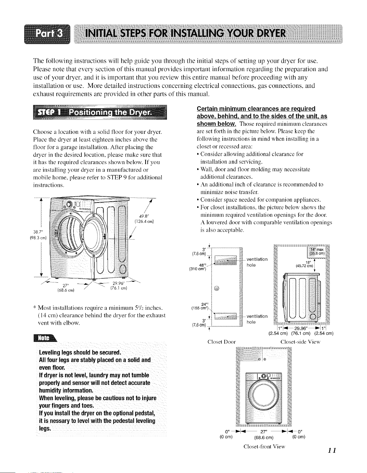
Choose a location with a solid floor for your dryer.
Place the dryer at least eighteen inches above the
floor for a garage installation. After placing the
dryer in the desired location, please make sure that
it has the required clearances shown below. If you
are installing your dryer in a manufactured or
mobile home, please refer to STEP 9 for additional
instructions.
38.7"
(98.3 cm)
/
49.8"
(126.4 cm)
27"
(68.6 cm)
* Most installations require a minimum 572 inches.
(14 cm) clearance behind the dryer for the exhaust
vent with elbow.
Leveling legs should be secured.
All four legs are stably placed on a solid and
even floor.
If dryer is not level, laundry may not tumble
properly and sensor will not detect accurate
humidity information.
When leveling, please be cautious not to injure
your fingers and toes.
If you install the dryer on the optional pedstal,
it is nessary to level with the pedestal leveling
legs.
Certain minimum clearances are required
above, behind, and to the sides of the unit, as
shown below. Those required mininmm clearances
are set forth in the picture below. Please keep the
following instructions in mind when installing in a
closet or recessed area:
• Consider allowing additional clearance for
installation and servicing.
• Wall, door and floor molding may necessitate
additional clearances.
• An additional inch of clearance is recommended to
minimize noise transfer.
• Consider space needed for companion appliances.
• For closet installations, the picture below shows the
nlininmm required ventilation openings t_r the door.
A louvered door with comparable ventilation openings
is also acceptable.
3" /
(310 cm _)
2#*
(7.6cm) ......................................................
Closet Door
ventilation
hole
ventilation
hole
(2.54 cm) (76.1 cm) (2.54 cm)
Closet-side View
O"_ 27"
(0 cm) (68.6 cm)
Closet-flont View
(0 cm)
11
Once in position, adjust the leveling legs of the dryer
until it is level from left to right and front to back.
The leveling legs must remain firmly on the floor
and the dryer should not rock. The maximum slope
of the dryer from left to right or front to back should
not exceed 2.5 cm (1 inch). If the dryer is not level,
and if the slope exceeds 2.5 cm (1 inch), a load may
not tumble properly and internal sensors may
malfunction. Note: Other sections of this manual
also provide important information concerning the
placement of and clearances for your dryer. Please
review this entire manual before proceeding with any
installation.
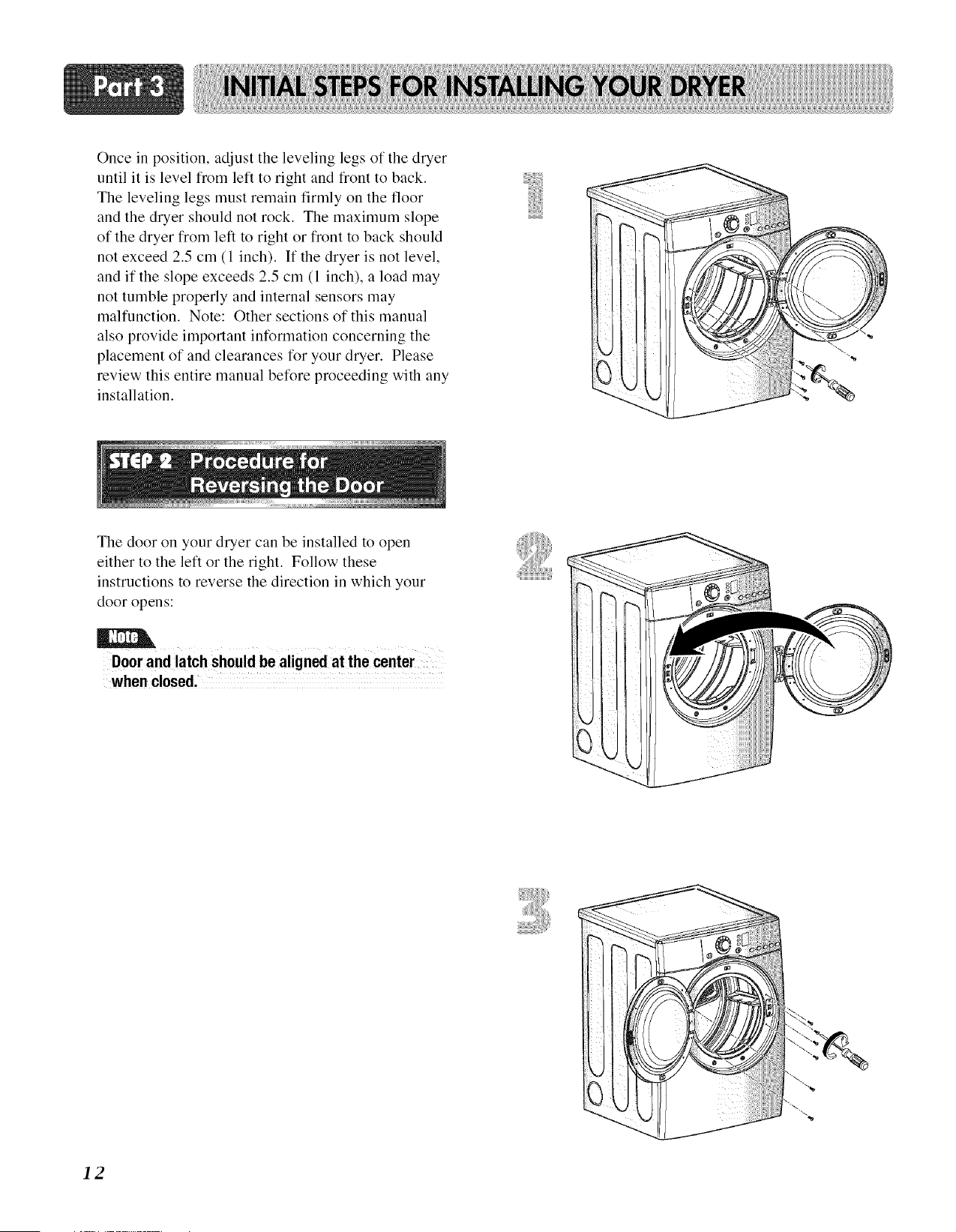
The door on your dryer can be installed to open
either to the left or the right. Follow these
instructions to reverse the direction in which your
door opens:
i I i
Door and latch should be aligned at the center
when closed.
12
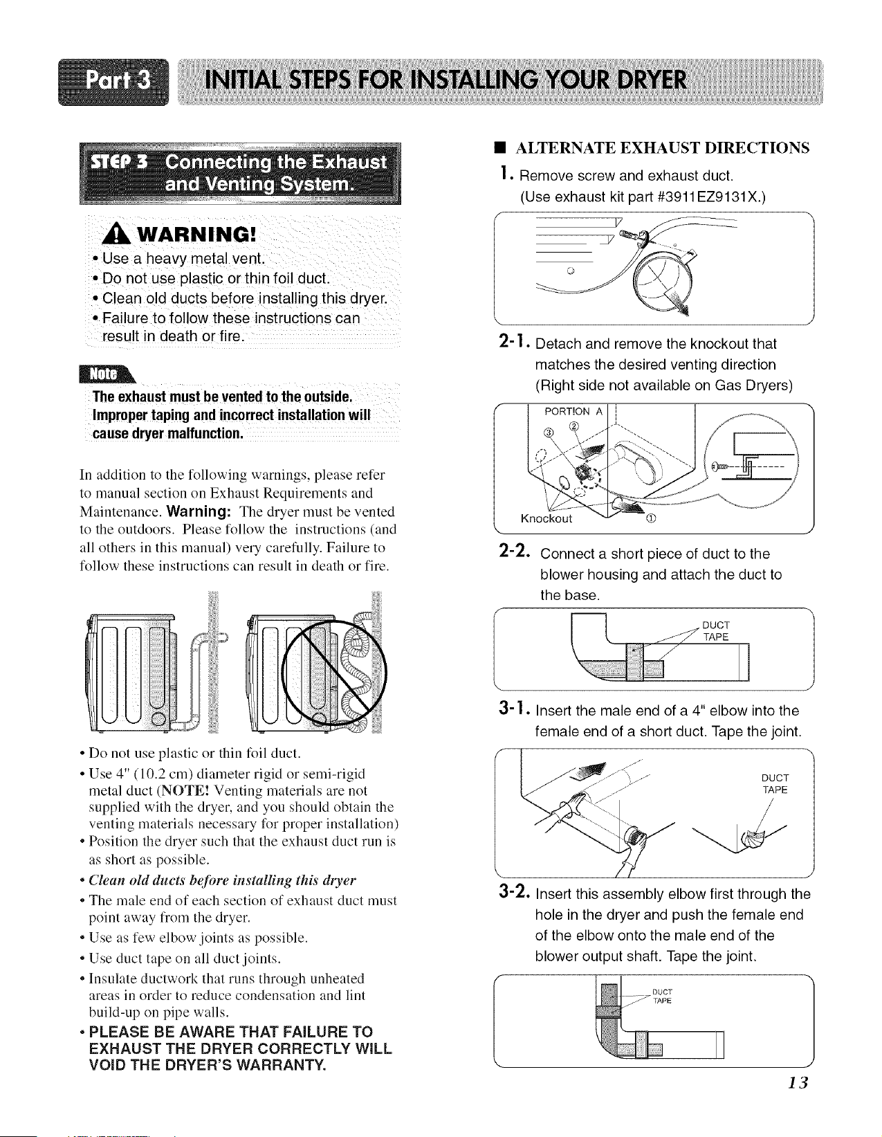
WARNING!
• Use a heavy metal vent.
• Do not use plastic or thin foil duct.
• Clean old ducts before installing this dryer.
• Failure to follow these instructions can
result in death or fire.
The exhaust must be vented to the outside.
Improper taping and incorrect installation wil!
cause dryer malfunction,
In addition to the following warnings, please refer
to manual section on Exhaust Requirements and
Maintenance. Warning: The dryer must be vented
to the outdoors. Please follow the instructions (and
all others in this manual) very carefully. Failure to
follow these instructions can result in death or fire.
• Do not use plastic or thin foil duct.
• Use 4" (10.2 cm) diameter rigid or semi-rigid
metal duct (NOTE! Venting materials are not
supplied with the dryer, and you should obtain the
venting materials necessary for proper installation)
• Position the dryer such that the exhaust duct run is
as short as possible.
• Clean old ducts' before installing this' dryer
• The male end of each section of exhaust duct must
point away from the dryer.
• Use as few elbow joints as possible.
• Use duct tape on all duct joints.
• Insulate ductwork that runs through unheated
areas in order to reduce condensation and lint
build-up on pipe walls.
• PLEASE BE AWARE THAT FAILURE TO
EXHAUST THE DRYER CORRECTLY WiLL
VOiD THE DRYER'S WARRANTY.
• ALTERNATE EXHAUST DIRECTIONS
]. Remove screw and exhaust duct.
(Use exhaust kit part #3911 EZ9131X.)
Detach and remove the knockout that
matches the desired venting direction
(Right side not available on Gas Dryers)
PORTION A _%
Knockout Q
\
2-2.
f
\
Connect a short piece of duct to the
blower housing and attach the duct to
the base.
3-1. Insert the male end of a 4" elbow into the
female end of a short duct. Tape the joint.
DUCT
TAPE
3-2. Insert this assembly elbow first through the
hole in the dryer and push the female end
of the elbow onto the male end of the
blower output shaft. Tape the joint.
13
s
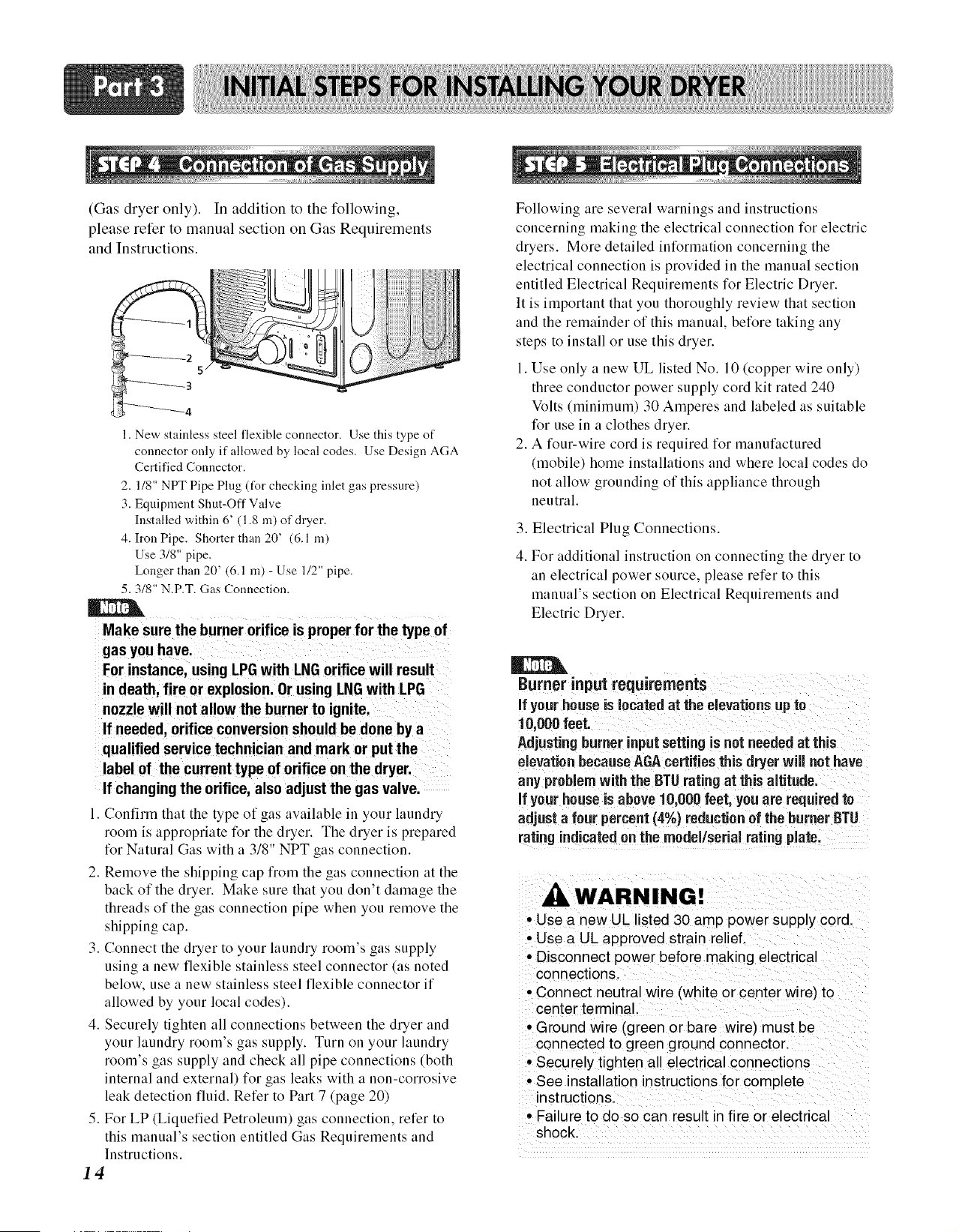
(Ga: dryer only). In addition to the following,
please refer to manual section on Gas Requirements
and Instructions.
1. New stainless steel flexible connector. Use this type of
connector only if allowed by local codes. Use Design AGA
Certified Connector.
2. 1/8" NPT Pipe Plug (tUr checking inlet gas pressure)
3. Equipment Shut-Off Valve
Installed within 6' (1.8 m) of dryer.
4. Iron Pipe. Shorter than 20' (6.1 m)
Use 3/8" pipe.
Longer than 20' (6.1 m) - Use 1/2" pipe.
5.3/8" N.P.T. Gas Connection.
Make sure the burner orifice is proper for the type of
For instance, using LPG with LNGorifice will result
in death, fire or explosion. Or using LNG with LPG
nozzle will not allow the burner to ignite.
If needed, orifice conversion should be done by a
qualified service technician and mark or put the
label of the current type of orifice on the dryer.
If changing the orifice, also adjust the gas valve.
I. Confirln that the type of gas available in your laundry
room is appropriate IBr the dryer. The dryer is prepared
3 T_ o *
IBr Natural Gas with a, 18 NPT _as connection.
2. Remove the shipping cap fiom the gas connection at the
back of the dryer. Make sure that you don't damage the
threads of the gas connection pipe when you remove the
shipping cap.
3. Connect the dryer to your laundry room's gas supply
using a new flexible stainless steel connector (as noted
below, use a new stainless steel flexible connector if
allowed by your local codes).
4. Securely tighten all connections between the dryer and
your laundry room's gas supply. Turn on your laundry
room's gas supply and check all pipe connections (both
internal and external) for gas leaks with a non-corrosive
leak detection fluid. Refer to Part 7 (page 20)
5. For LP (Liquefied Petroleum) gas connection, refer to
this manual's section entitled Gas Requirements and
Instructions.
14
Following are several warnings and instructions
concerning makiug the electrical connection for electric
dryers. More detailed iutbrmatiou concerning the
electrical connection is provided in the manual section
entitled Electrical Requirements for Electric Dryer.
It is important that you thoroughly review that section
and the remainder of this manual, belBre taking any
steps to install or use this dryer.
1. Use only a new UL listed No. 10 (copper wire only)
three conductor power supply cord kit rated 240
Volts (minimum) 30 Amperes and labeled as suitable
l_r use in a clothes dryer.
2. A four-wire cord is required for manufactured
(mobile) home installations and where local codes do
not allow grounding of this appliance through
neutral.
3. Electrical Plug Connections.
4. For additional instruction on connecting the dryer to
an electrical power source, please refer to this
manual's section on Electrical Requirements and
Electric Dryer.
Burner input requirements
if your house is located at the elevations up to
10,000 feet.
Adjustingburner input setting iS not needed at this
elevationbecause AGAcertifies this dryer will not have
any problemwith the BTUrating at this altitude.
if your houseis above 10,ooo feet, you are requiredto
adjust a four percent (4%) reduction of the burner BTU
rating indicated on the model/serial rating
WARNING!
• Use a new UL listed 30 amp power supply cord
• Use a UL approved strain relief
• Disconnect power before making electrical
connections
• Connect neutral wire (white or center wire) to
center terminal
• Ground wire (green or bare wire) must be
connected to green ground connector
• Securely tighten all electrical connections
• See installation instructions for complete
instructions
• Failure to do so can result in fire or electrical
shock
Prior to the first use of this appliance, use all-
purpose cleaning products or a solution of detergent
and watei; with damp cloth to remove from the
inside of the dryer drum/drying compartment any
dust or dirt that may have accumulated inside the
dryer. Plug-in your dryer after reviewing the
following parts on your dryer's Electrical
Requirements.
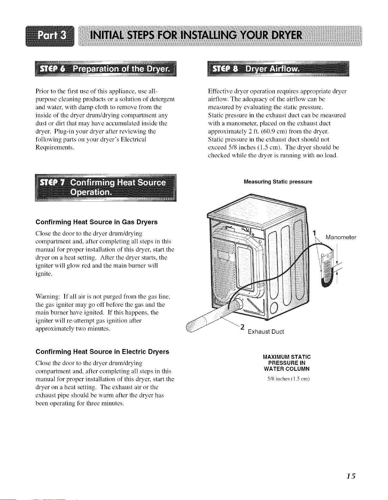
Effective dryer operation requires appropriate dryer
airflow. The adequacy of the airflow can be
measured by evaluating the static pressure.
Static pressure in the exhaust duct can be measured
with a manometer, placed on the exhaust duct
approximately 2 ft. (60.9 cm) from the dryer.
Static pressure in the exhaust duct should not
exceed 5/8 inches (1.5 cm). The dryer should be
checked while the dryer is running with no load.
Measuring Static pressure
Confirming Heat Source in Gas Dryers
Close the door to the dryer drum/drying
compartment and, after completing all steps in this
manual for proper installation of this dryer, start the
dryer on a heat setting. After the dryer starts, the
igniter will glow red and the main burner will
ignite.
Manometer
Warning: If all air is not purged from the gas line,
the gas igniter may go off before the gas and the
main burner have ignited. If this happens, the
igniter will re-attempt gas ignition alter
approximately two minutes.
Exhaust Duct
Confirming Heat Source in Electric Dryers
Close the door to the dryer drum/drying
compartment and, alter completing all steps in this
manual for proper installation of this dryer, start the
dryer on a heat setting. The exhaust air or the
exhaust pipe should be warm alter the dryer has
been operating for three minutes.
MAXIMUM STATIC
PRESSURE IN
WATER COLUMN
518 inches (1.5 cm)
The following instructions are applicable to
installations of the dryer in a manufactured or
mobile home. Any installation in a manufactured or
mobile home must comply with the Manut:actured
Home Construction and Safety Standards Title 24
CFR, Part 32-80 or Standard CAN/CSAOZ240 MH
and local codes and ordinances. If you are
uncertain whether your proposed installation will
comply with these standards, please contact a
service and installation professional for assistance.
The following instructions apply to any installation
of the dryer in a manufactured or mobile home:
1) The electrical connection for an electric dryer
must be a 4-wire connection. More detailed
information concerning the electrical connection
is provided at the manual section entitled
Electrical Requirements for Electric Dryer
2) To reduce the risk of combustion and fire, the
dryer must be vented to the outside.
3)
4)
5)
6)
7)
8)
9)
Electric dryers may be vented to the outside
using the back, left, right, or bottom panel.
Gas dryers may be vented to the outside using the
back, left, or bottom panel. Gas dryers may not
be vented to the outside using the right side panel
because of the burner housing.
The dryer exhaust duct must be affixed securely
to the manufactured or mobile home structure,
the exhaust duct must be made of a material that
will resist fire and combustion, and it is
recommended that you use a rigid or flexible
metal pipe.
DO NOT connect the exhaust duct with any other
duct, vent, chimney, or other exhaust duct.
Make sure the dryer has adequate access to
outside fresh air to ensure proper operation. The
opening for outside fresh air must be at least 25
in_ (163 cm:).
It is important that the clearance of the duct from
any combustible construction be at least 2 inches
(5 cm), and, when venting the dryer to the
outdoors, the dryer can be installed with a
clearance of 1 inch at the sides and back of the
dryer.
Please be aware that venting materials are not
supplied with the dryer. You should obtain the
venting materials necessary for proper
installation.
• DO NOT connect exhaust ducts with
metal screws or fasteners that extend
into the ducL
• Failure to do so can result in death,
explosion, or fire.
WARNING!
• DO NOT vent the exhaust duct under the
manufactured or mobile home.
• Failure to do so can result in death,
explosion, or fire.
16
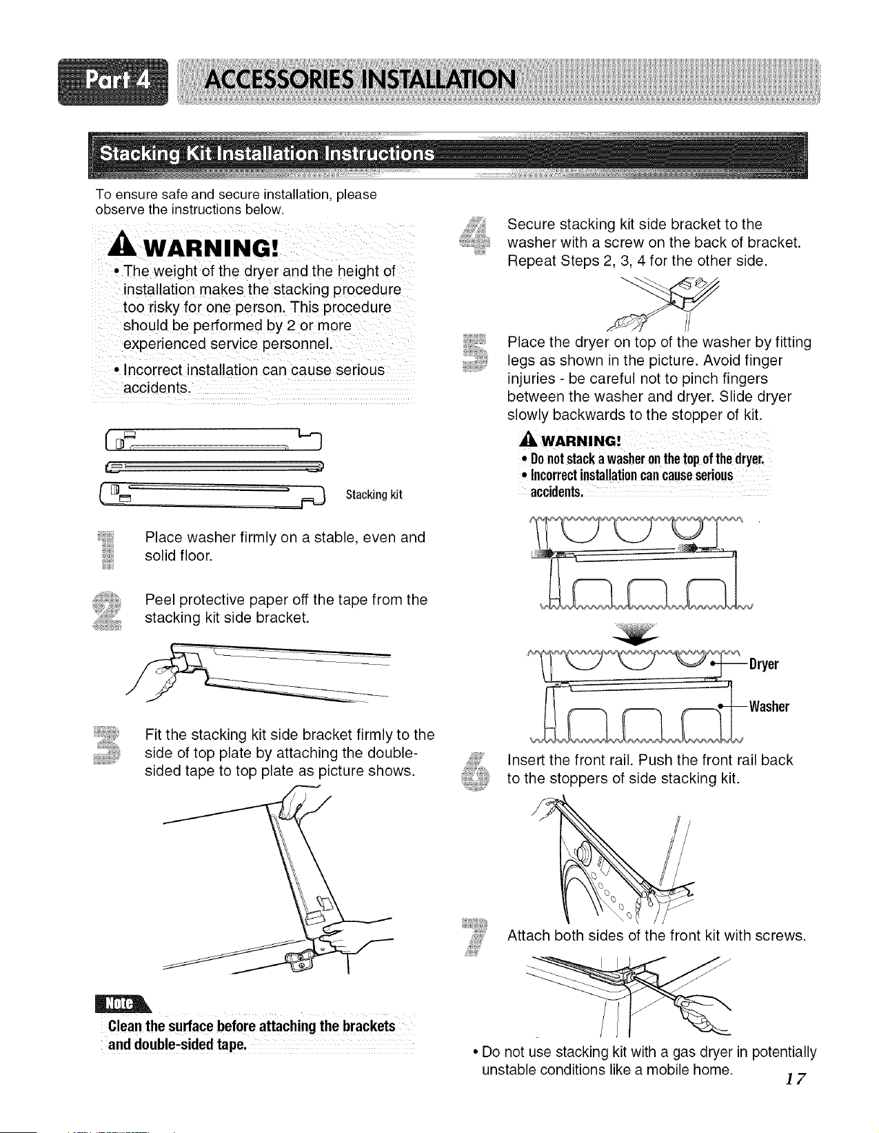
To ensure safe and secure installation, please
observe the instructions below.
WARNING!
• The weight of the dryer and the height of
installation makes the stacking procedure
too risky for one person. This procedure
should be performed by 2 or more
experienced service personnel.
• Incorrect installation can cause serious
accidents.
Fq_]_, ,_
6__ J
Stacking kit
Place washer firmly on a stable, even and
solid floor.
Secure stacking kit side bracket to the
washer with a screw on the back of bracket.
Repeat Steps 2, 3, 4 for the other side.
Place the dryer on top of the washer by fitting
legs as shown in the picture. Avoid finger
injuries - be careful not to pinch fingers
between the washer and dryer. Slide dryer
slowly backwards to the stopper of kit.
• Donotstacka washeronthe topof the dryer.
• Incorrectinstallationcancauseserious
accidents.
Peel protective paper off the tape from the
stacking kit side bracket.
Fit the stacking kit side bracket firmly to the
side of top plate by attaching the double-
sided tape to top plate as picture shows.
Clean the surface before attaching the brackets
Insert the front rail. Push the front rail back
to the stoppers of side stacking kit.
Attach both sides of the front kit with screws.
_
• Do not use stacking kit with a gas dryer in potentially
unstable conditions like a mobile home.
17
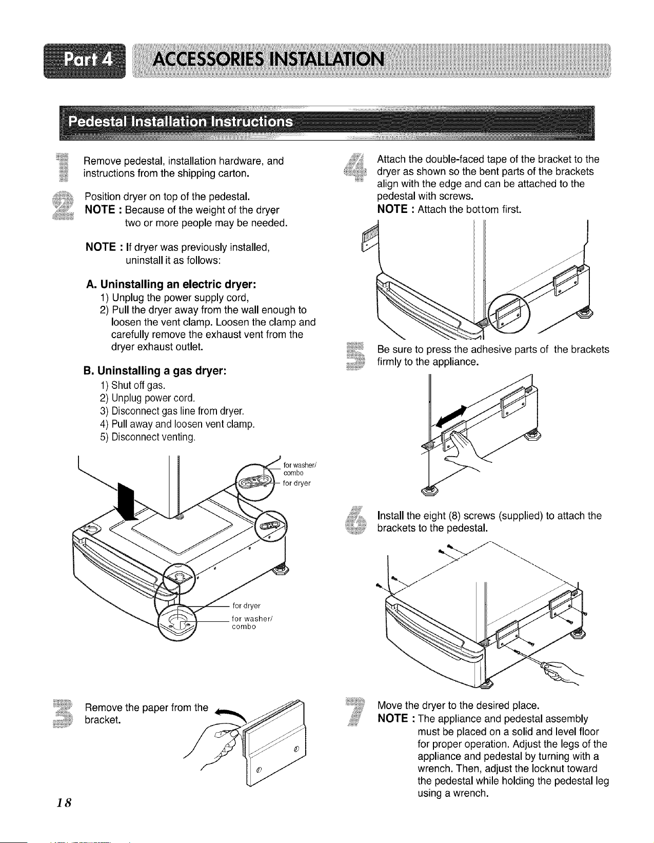
Remove pedestal, installation hardware, and
instructions from the shipping carton.
Position dryer on top of the pedestal.
NOTE : Because of the weight of the dryer
two or more people may be needed.
NOTE • If dryer was previously installed,
uninstall it as follows:
A. Uninstalling an electric dryer:
1) Unplug the power supply cord,
2) Pull the dryer away from the wall enough to
loosen the vent clamp. Loosen the clamp and
carefully remove the exhaust vent from the
dryer exhaust outlet.
B. Uninstalling a gas dryer:
1) Shut off gas.
2) Unplug power cord.
3) Disconnect gas line from dryer.
4) Pull away and loosen vent clamp.
5) Disconnect venting.
Attach the double-faced tape of the bracket to the
dryer as shown so the bent parts of the brackets
align with the edge and can be attached to the
pedestal with screws.
NOTE : Attach the bottom first.
I
Be sure to press the adhesive parts of the brackets
firmly to the appliance.
for dryer
for washer/
combo
combo
Install the eight (8) screws (supplied) to attach the
brackets to the pedestal.
18
Remove the paper from the
bracket.
Move the dryer to the desired place.
NOTE • The appliance and pedestal assembly
must be placed on a solid and level floor
for proper operation. Adjust the legs of the
appliance and pedestal by turning with a
wrench. Then, adjust the Iocknut toward
the pedestal while holding the pedestal leg
using a wrench.
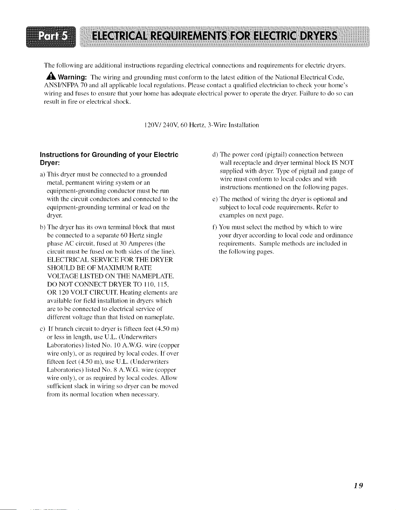
The following are additional instructions regarding electrical connections and requirements for electric dryers.
Warning: The wiring and grounding must conform to the latest edition of the National Electrical Code,
ANSI/NFPA 70 and all applicable local regulations. Please contact a qualified electrician to check your home's
wiring and fuses to ensure that your home has adequate electrical power to operate the dryer. Failure to do so can
result in fire or electrical shock.
120V/240V, 60 Hertz, 3-Wire Installation
Instructions for Grounding of your Electric
Dryer:
a) This dryer must be connected to a grounded
metal, permanent wiring system or an
equipment-grounding conductor must be run
with the circuit conductors and connected to the
equipment-grounding terminal or lead on the
dryer.
b) The dryer has its own terminal block that must
be connected to a separate 60 Hertz single
phase AC circuit, fused at 30 Amperes (the
circuit must be fused on both sides of the line).
ELECTRICAL SERVICE FOR THE DRYER
SHOULD BE OF MAXIMUM RATE
VOLTAGE LISTED ON THE NAMEPLATE.
DO NOT CONNECT DRYER TO 110, 115,
OR 120 VOLT CIRCUIT. Heating elements are
available for field installation in dryers which
are to be connected to electrical service of
different voltage than that listed on nameplate.
c) If branch circuit to dryer is fifteen feet (4.50 m)
or less in length, use U.L. (Underwriters
Laboratories) listed No. 10 A.W.G. wire (copper
wire only), or as required by local codes. If over
fifteen feet (4.50 m), use U.L. (Underwriters
Laboratories) listed No. 8 A.W.G. wire (copper
wire only), or as required by local codes. Allow
sufficient slack in wiring so dryer can be moved
from its normal location when necessary.
d) The power cord (pigtail) connection between
wall receptacle and dryer terminal block IS NOT
supplied with dryer. Type of pigtail and gauge of
wire must conform to local codes and with
instructions mentioned on the following pages.
e) The method of wiring the dryer is optional and
subject to local code requirements. Refer to
examples on next page.
f) You must select the method by which to wire
your dryer according to local code and ordinance
requirements. Sample methods are included in
the following pages.
19
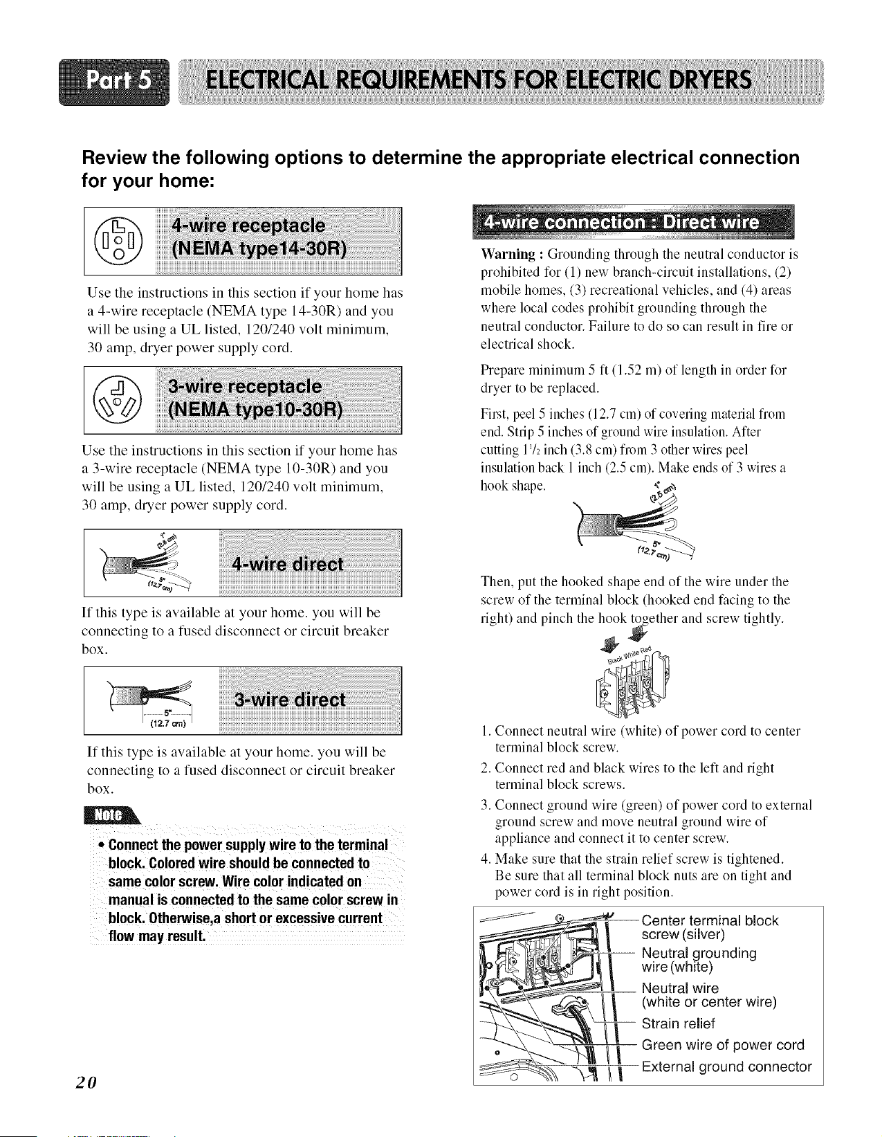
Review the following options to determine the appropriate electrical connection
for your home:
@
Use the instructions in this section if your home has
a 4-wire receptacle (NEMA type 14-30R) and you
will be using a UL listed, 1201240 volt minimum,
30 amp, dryer power supply cord.
Use the instructions in this section if your home has
a 3-wire receptacle (NEMA type 10-30R) and you
will be using a UL listed, 1201240 volt minimum,
30 amp, dryer power supply cord.
Warning : Grounding through the neutral conductor is
prohibited for (1) new branch-circuit installations, (2)
mobile homes, (3) recreational vehicles, and (4) areas
where local codes prohibit grounding through the
neutral conductor. Failure to do so can result in tire or
electrical shock.
Prepare nlininmm 5 ft (1.52 m) of length in order tk)r
dryer to be replaced.
First, peel 5 inches (12.7 cm) of covering material from
end. Strip 5 inches of ground wire insulation. After
cutting IV2inch (3.8 cm) from 3 other wires peel
insulation back 1 inch (2.5 cm). Make ends of 3 wires a
hook shape.
If this type is available at your home. you will be
connecting to a fused disconnect or circuit breaker
box.
If this type is available at your home. you will be
connecting to a fused disconnect or circuit breaker
box.
• Connect the power supply wire to the termina
block. Colored wire should be connected to
same color screw. Wire color indicated on
manual is connected to the same color screw in
block. Otherwise,a short or excessive current
flow may result.
2O
Then, put the hooked shape end of the wire under the
screw of the terminal block (hooked end facing to the
right) and pinch the hook together and screw tightly.
1. Connect neutral wire (white) of power cord to center
terminal block screw.
2. Connect red and black wires to the left and right
terminal block screws.
3. Connect ground wire (green) of power cord to external
ground screw and move neutral ground wire of
appliance and connect it to center screw.
4. Make sure that the strain relief screw is tightened.
Be sure that all terminal block nuts are on tight and
power cord is in right position.
Center terminal block
screw (silver)
Neutral grounding
wire (white)
Neutral wire
(white or center wire)
Strain relief
Green wire of power cord
External ground connector
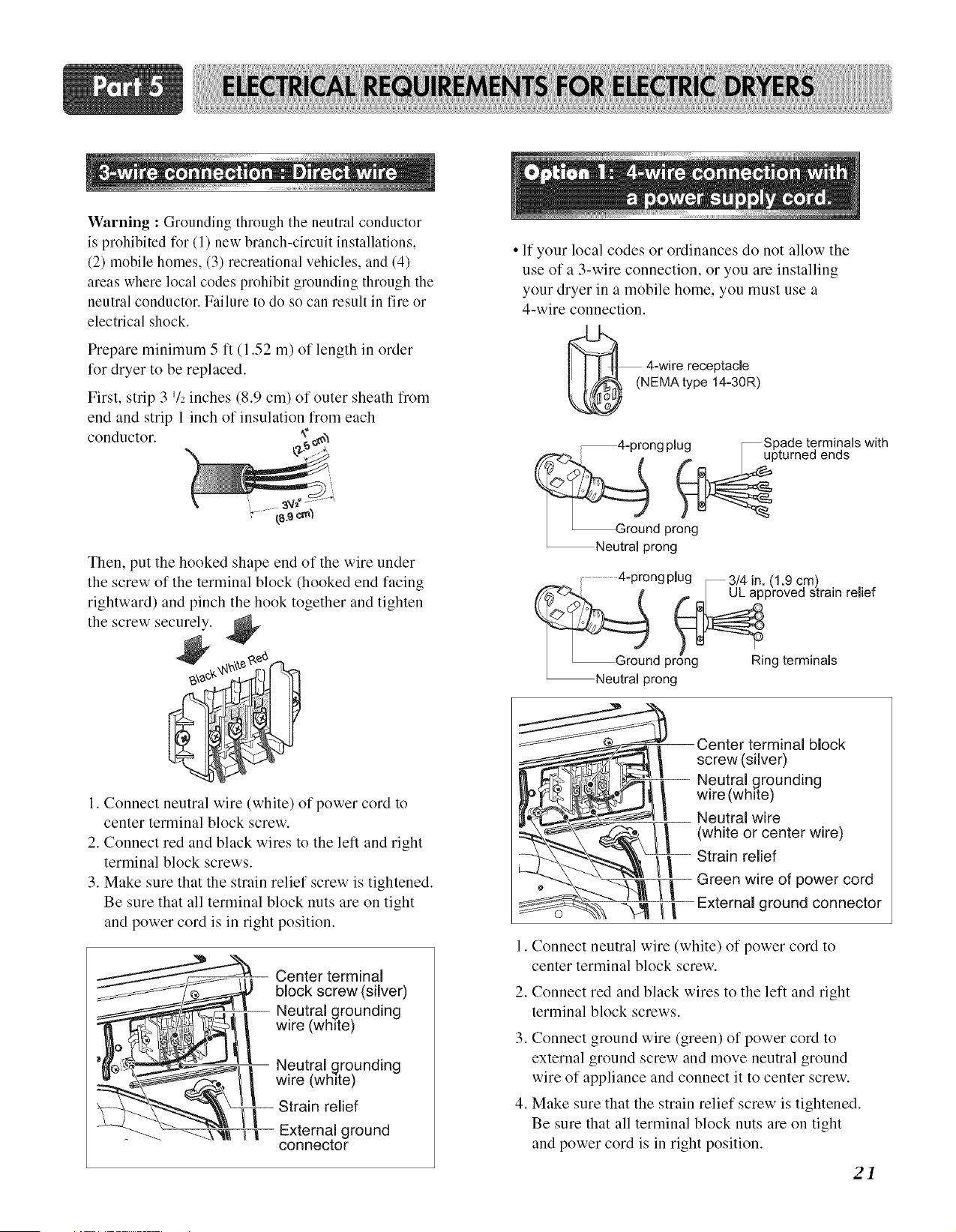
Warning : Grounding through the neutral conductor
is prohibited for (1) new branch-circuit installations,
(2) mobile homes, (3) recreational vehicles, and (4)
areas where local codes prohibit grounding through the
neutral conductor. Failure to do so can result in fire or
electrical shock.
Prepare minimum 5 ft (1.52 m) of length in order
for dryer to be replaced.
First, strip 3 72 inches (8.9 cm) of outer sheath from
end and strip 1 inch of insulation from each
conductor. _
Then, put the hooked shape end of the wire under
the screw of the terminal block (hooked end facing
rightward) and pinch the hook together and tighten
the screw securely.
1. Connect neutral wire (white) of power cord to
center terminal block screw.
2. Connect red and black wires to the left and right
terminal block screws.
3. Make sure that the strain relief screw is tightened.
Be sure that all terminal block nuts are on tight
and power cord is in right position.
__ Neutral _rounding
_{_/_/;_ _ wire _wh re)
'_Z __,! Neutra, grounding
8_'"_% __ _ wire (wh,te)
_ LLL_Strainrelief
_" _\ I/_F- External ground
connector
• If your local codes or ordinances do not allow the
use of a 3-wire connection, or you are installing
your dryer in a mobile home, you must use a
4-wire connection.
( 4-wire receptacle
NEMAtype 14-30R)
-prona plua _ Spade terminals with
_pturned ends
d prong
_Neutral prong
4"prongplug _3/4 in. (1.9 cm)
pproved strain relief
d prong Ring terminals
rong
Center terminal block
screw (silver)
-- Neutral grounding
wire (white)
Neutral wire
(white or center wire)
Strain relief
Green wire of power cord
External ground connector
1. Connect neutral wire (white) of power cord to
center terminal block screw.
2. Connect red and black wires to the left and right
terminal block screws.
3. Connect ground wire (green) of power cord to
external ground screw and move neutral ground
wire of appliance and connect it to center screw.
4. Make sure that the strain relief screw is tightened.
Be sure that all terminal block nuts are on tight
and power cord is in right position.
21
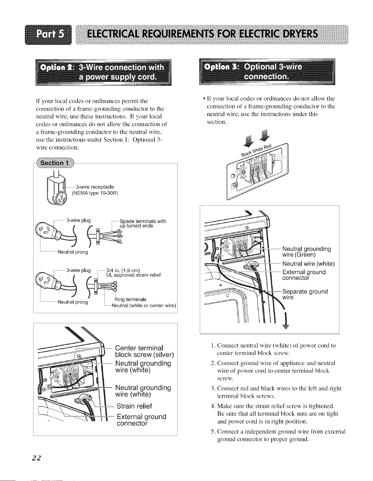
If your local codes or ordinances permit the
connection of a frame-grounding conductor to the
neutral wire, use these instructions. If your local
codes or ordinances do not allow the connection of
a frame-grounding conductor to the neutral wire,
use the instructions under Section 1: Optional 3-
wire connection.
3-wire receptacle
EMAtype 10-30R)
-_e plug__ Spade tsgm indasls with
Neutral prong
u3-Wire plug _ 3/4 in. (1.9 cm)
pproved strain relief
rona" Ring terminals
_ _Neutral (white or center wire
|
|
Center terminal
block screw (silver)
Neutral grounding
wire (white)
Neutral grounding
wire (white)
Strain relief
External ground
connector
22
• If your local codes or ordinances do not allow the
connection of a frame-grounding conductor to the
neutral wire, use the instructions under this
section.
I///
Neutral grounding
wire (Green)
Neutral wire (white)
External ground
connector
--Separate ground
lre
[
.
2.
.
4.
.
Connect neutral wire (white) of power cord to
center terminal block screw.
Connect ground wire of appliance and neutral
wire of power cord to center terminal block
screw.
Connect red and black wires to the left and right
terminal block screws.
Make sure the strain relief screw is tightened.
Be sure that all terminal block nuts are on tight
and power cord is in right position.
Connect a independent ground wire from external
ground connector to proper ground.
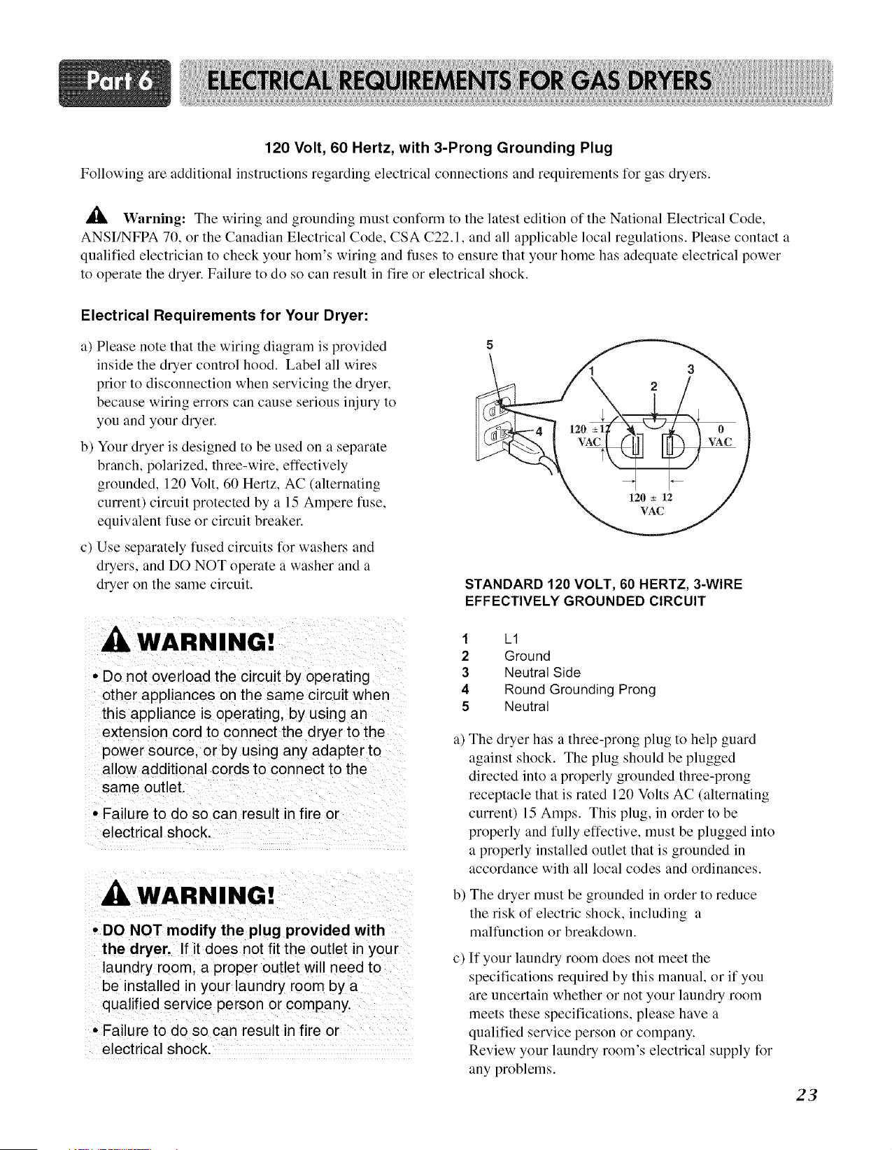
120 Volt, 60 Hertz, with 3-Prong Grounding Plug
Following are additional instructions regarding electrical connections and requirements for gas dryers.
Warning: The wiring and grounding must conform to the latest edition of the National Electrical Code,
ANSI/NFPA 70, or the Canadian Electrical Code, CSA C22.1, and all applicable local regulations. Please contact a
qualified electrician to check your hom's wiring and fuses to ensure that your home has adequate electrical power
to operate the dryer. Failure to do so can result in fire or electrical shock.
Electrical Requirements for Your Dryer:
a) Please note that the wiring diagram is provided
inside the dryer control hood. Label all wires
prior to disconnection when servicing the dryer,
because wiring errors can cause serious injury to
you and your dryer.
b) Your dryer is designed to be used on a separate
branch, polarized, three-wire, effectively
grounded, 120 Volt, 60 Hertz, AC (alternating
current) circuit protected by a 15 Ampere fuse,
equivalent fuse or circuit breaker.
c) Use separately fused circuits for washers and
dryers, and DO NOT operate a washer and a
dryer on the same circuit.
WARNING!
• Do not overload the circuit by operating
other appliances on the same circuit when
this appliance is operating, by using an
extension cord to connect the dryer to the
power source, or by using any adapter to
allow additional cords to connect to the
same outlet.
• Failure to do so can result in fire or
electrical shock.
WARN
• DO NOT modify the plug provided with
the dryer, If it does not fit the outlet in your
laundry room a proper outlet w I! need to
be installed n your laundry room by a
qualified service person or company,
, Failure to do so can result in fire or
electrical shock.
STANDARD 120 VOLT, 60 HERTZ, 3-WIRE
EFFECTIVELY GROUNDED CIRCUIT
1
2
3
4
5
L1
Ground
Neutral Side
Round Grounding Prong
Neutral
a)The dryer has a three-prong plug to help guard
against shock. The plug should be plugged
directed into a properly grounded three-prong
receptacle that is rated 120 Volts AC (alternating
current) 15 Amps. This plug, in order to be
properly and tully effective, must be plugged into
a properly installed outlet that is grounded in
accordance with all local codes and ordinances.
b) The dryer must be grounded in order to reduce
the risk of electric shock, including a
malfunction or breakdown.
c) If your laundry room does not meet the
specifications required by this manual, or if you
are uncertain whether or not your laundry room
meets these specifications, please have a
qualified service person or company.
Review your laundry room's electrical supply for
any problems.
23
Following are important instructions and information concerning the requirements for the gas supply and service for
gas dryers. _ Warning: The gas supply and service for a gas dryer must comply with all local codes and
ordinances. In the absence of any local codes or ordinances in your area, the gas supply and service for your gas
dryer must comply with the latest edition of the National Fuel Gas Code, ANSI Z223. I/NFPA 54. Failure to do so can
result in death, explosion, or fire.
1. Gas supply requirements: Liquefied Petroleum
(L.P.) Gas (2,500 Btu/ft3 (93.1 MJ/m3)) service
must be provided at 10 + 1.5 in. water column
pressure.
2. Do not attempt to connect the dryer to Liquified
Petroleum (LP Gas) Gas service without a
qualified professional.
3. Isolate the dryer from the gas supply piping
system by closing its individual manual shut-off
valve during any pressure testing of the gas
supply system at test pressure equal to or less
than 211 psi (3.45 kPa).
4. Supply Line Requirements. Your laundry room
must have a rigid gas supply line to your dryer.
In the United States, an individual manual shutoff
valve MUST be installed within at least 6 feet
(1.8 m) of the dryer, in accordance with the
National Fuel Gas Code ANSI Z223.1. A 118 in.
N.P.T. pipe plug must be installed as shown.
WAR
• DO NOT attempt any disassembly Of the
dryer. Any disassemb!y requires the
attention and tools of an authorized and
qualified service pers0n or company.
• Failure to do so can result in death
explosion, or fire,
24
.
.
If using a rigid pipe, the rigid pipe should be 112
inch IPS. If acceptable under local codes and
ordinances and when acceptable to your gas
supplier, 318 inch approved tubing may be used
where lengths are less than 20 feet (6.1 m).
Larger tubing should be used for lengths in
excess of 20 feet (6.1 m). It is also important that
you use pipe joint compound that is insoluble in
LP gas.
To reduce the danger of gas leaks, explosion, and
fire, please follow and observe the following
instructions and WARNINGS.
Connect the dryer to the type of gas shown on the
nameplate.
Use new flexible stainless steel connectors.
Use Teflon tape and pipe joint compound
insoluble in LP gas on all pipe threads.
Purge gas supply of air and sediment before
connecting the gas supply to the dryer in order to
prevent gas valve contamination. Before
tightening connection between gas supply and
dryer, purge remaining air until odor of gas is
identified.
• DO NOT use an open flame to inspect for gas
leaks; instead use a non-corrosive leak detection
fluid
WARNING!
• Use a new AGA or CSA approved gas
supply line.
• Install a shut-off valve.
• Securely tighten all gas connections
• If connected to LP, have a qualified person
make sure gas pressure does not exceed
13 in. water column.
• Examples of a qualified person include
licensed heating personnel, authorized gas
company personnel, and authorized service
personnel.
• Failure to do so can result in death
explosion or fire.
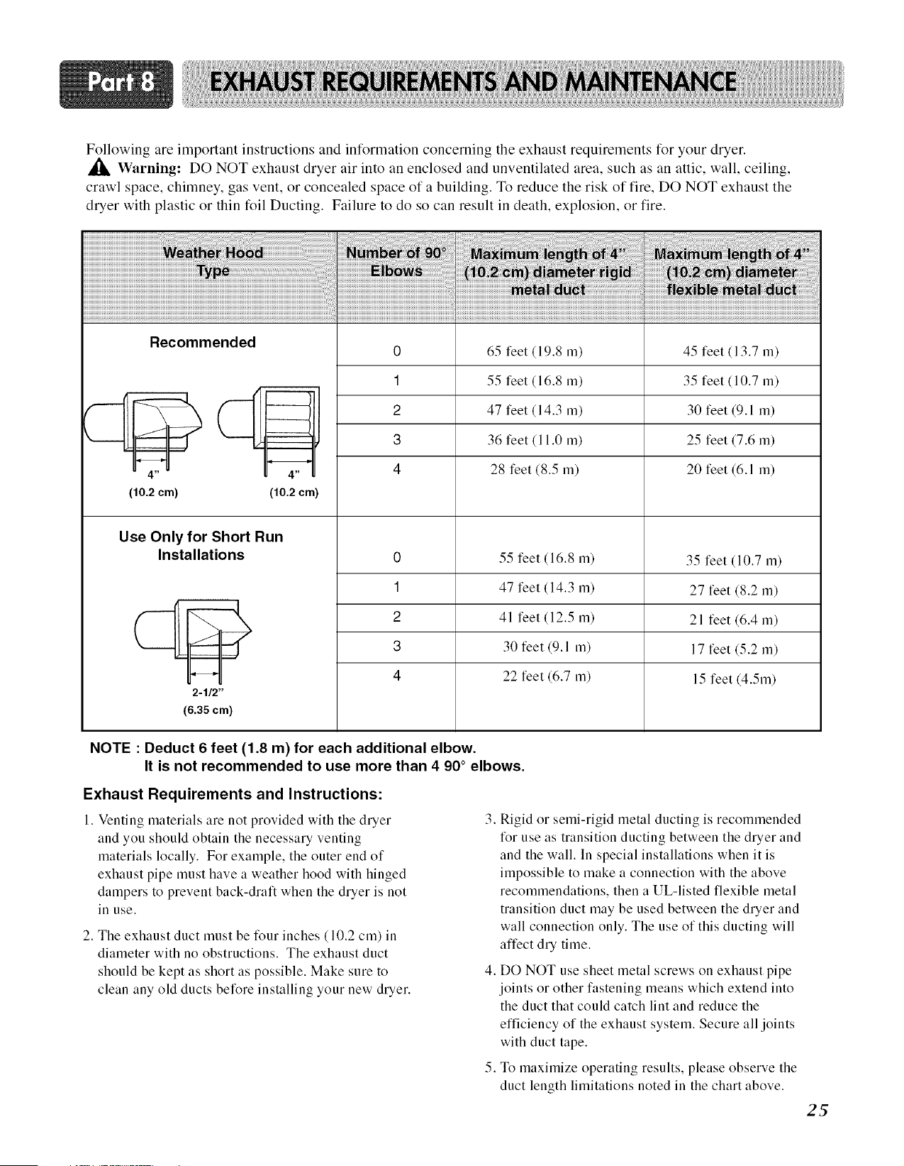
Following are important instructions and information concerning the exhaust requirements for your dryer.
Warning: DO NOT exhaust dryer air into an enclosed and unventilated area, such as an attic, wall, ceiling,
crawl space, chimney, gas vent, or concealed space of a building. To reduce the risk of fire, DO NOT exhaust the
dryer with plastic or thin foil Ducting. Failure to do so can result in death, explosion, or tire.
Recommended
0 65 feet (19.8 m) 45 feet (13.7 m)
1 55 feet (16.8 m) 35 feet (10.7 m)
2 47 feet (14.3 m) 30 feet (9.1 m)
3 36 feet (11.0 m) 25 feet (7.6 m)
4 28 feet (8.5 m) 20 feet (6.1 m)
_--- - 1H
4."
(10.2cm) (10.2cm)
Use Only for Short Run
Installations
55 feet (16.8 m)
35 feet (10.7 m)
1
2
3
4
n __
H
2-1/2"
(6.35 cm)
47 feet (14.3 m)
41 feet (12.5 m)
30 feet (9.1 m)
22 feet (6.7 m)
27 feet (8.2 m)
21 feet (6.4 m)
17 feet (5.2 m)
15 feet (4.5m)
NOTE : Deduct 6 feet (1.8 m) for each additional elbow.
It is not recommended to use more than 4 90° elbows.
Exhaust Requirements and Instructions:
1. Venting materials are not provided with the dryer
and you should obtain the necessary venting
materials locally. For example, the outer end of
exhaust pipe must have a weather hood with hinged
dampers to prevent back-draft when the dryer is not
in use.
2. The exhaust duct must be tBur inches (10.2 cm) in
diameter with no obstructions. The exhaust duct
should be kept as short as possible. Make sure to
clean any old ducts belBre installing your new dryer.
.
Rigid or semi-rigid metal ductiug is recomlneuded
IBr use as transition ductiug between the dryer and
and the wall. In special installations when it is
impossible to make a connection with the above
recommendations, then a UL-listed flexible metal
transition duct may be used between the dryer and
wall connection only. The use of this ductiug will
affect dry time.
4. DO NOT use sheet metal screws on exhaust pipe
joints or other fastening means which extend into
the duct that could catch lint and reduce the
efficiency of the exhaust system. Secure all joints
with duct tape.
5. To maximize operating results, please observe the
duct length limitations noted in the chart above.
2_
Exhaust and Dryer Maintenance
WARNING!
• Disconnect the dryer's electric power
prior to any cleaning or maintenance.
• Failure to do so can result in fire or
electrical shock
1. After one year of use, the interior and complete
exhaust system of the dryer should be examined
and cleaned if necessary.
2. Before one year of use, when duing performance has become
unsatisfactory,please examine and clean theexhaust duct for
better dwing performance.
3. Check the weather hoods Dequently to ensure
the dampers are moving Deely, that the dampers
are not pushed in and that nothing has been set
against the dampers.
4. A qualified service person or company should be
used to perform this maintenance.
5. A Flexible Metal Vent Kit, available at extra cost,
can be used to exhaust the dryer when it is placed
in hard to reach places. This Kit comes in two
pieces, one of which is attached to the dryer and
the other is attached to the wall exhaust outlet.
Following attachment of the two separate pieces
to the dryer and the wall, the dryer may be
returned to its final position, after which the two
pieces themselves can be connected.
7. Ordinarily, the dryer drum will need no care.
Wipe the exterior of the dryer as required, and
always wipe the exterior of the dryer in the event
any detergent, bleach, or other washing products
is spilled on the dryer.
8. Clean the control panel with a damp cloth as
necessary. Warning: spray pre-wash products
may damage the finish of the control panel.
9. Please clean the lint filter either before drying
each load or after drying each load.
10. Always make sure the lint filter is clean before
starting a new load, because a clogged lint filter
may increase drying times.
11. Annually remove the lint filter and attach it to
the vacuum duct. See item #2 above.
12. Please note that the wiring diagram is provided
inside the dryer control hood. Label all wires
prior to disconnection when servicing the dryer,
because wiring errors can cause serious injury
26 to you and your dryer.
Cleaning the Lint Screen
1. Clean the lint filter either before drying each load
or after drying each load. Always make sure the
lint filter is clean before starting a new load,
because a clogged lint filter may increase drying
times.
.
.
.
To clean, pull the lint screen straight up and roll
any lint off the screen with your fingers.
Do not rinse or wash screen to remove lint. Push
the lint screen firmly back into place.
Always ensure the lint screen is firmly secured
before running the dryer. Running the dryer with
a loose lint screen may cause overheating and
damage to the dryer and articles being dried.
Some articles of clothing may shed more lint than
others (towels for example), causing the lint
screen to fill rapidly. Remove lint from the lint
screen before and after drying these articles, such
as new towels.
.
.
In the event lint falls off of the lint screen and
into the dryer during removal, inspect the exhaust
hood and remove any lint.
Laundry detergent and fabric softener residue can
build up on the lint screen, causing longer drying
times. The screen is likely blocked if lint falls off
the screen. In order to prevent this type of build
up, and help ensure proper operation of your
dryer, clean the lint screen with a nylon brush
every six months or, if necessary, more
frequently. The lint filter can also be washed as
follows:
a) After rolling the lint off of the screen with your
fingers, wet both sides of the screen with hot or
warm water.
b) Wet a nylon brush with hot water and liquid
detergent and scrub the lint screen with the brush
to remove the buildup of detergent and fabric
softener.
c) After the residue has been removed, rinse screen
with hot water.
d) After drying the lint screen with a clean towel,
firmly replace the lint screen in your dryer.
Following are instructions for starting and using your new dryer. Please refer to specific sections of this manual for
more detailed information. Important Warning: To reduce the risk of tire, electric shock, or injury to person, read
this entire manual, mcludm_ the IMPORTANT SAFETY INSTRUCTIONS, before operating this dryer.
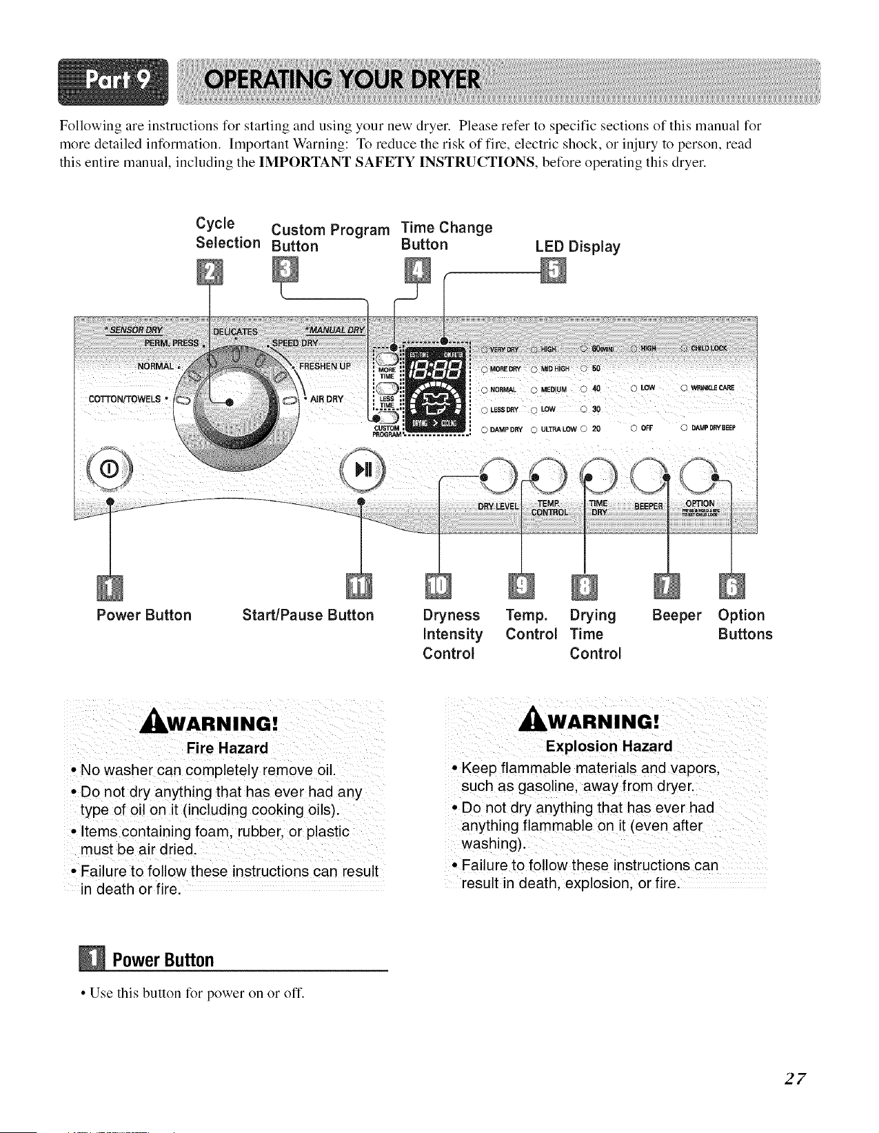
Cycle Custom Program Time Change
Selection Button Button
LED Display
COTTON/TOWELS •
© ,ESSD_ OL0W Q30
CUSTOM O DAMPDRY @ ULTRALOW Q 20 G OFF () DAMPDRYBEEP
PROGRAM'
Power Button Start/Pause Button
Dryness Temp, Drying Beeper Option
Intensity Control Time Buttons
Control Control
WARNING!
Fire Hazard
• No washer can completely remove oil.
• Do not dry anything that has ever had any
type of oil on it (including cooking oils)•
• Items containing foam, rubber• or plastic
must be air dried•
• Failure to follow these instructions can result
in death or fire.
, WARNING!
Explosion Hazard
• Keep flammable materials and vapors.
such as gasoline• away from dryer.
• Do not dry anything that has ever had
anything flammable on it (even after
washing).
• Failure to follow these instructions can
result in death, explosion, or fire.
PowerButton
• Use this button for power on or off.
27
Selection
• Turn the knob to select the desired cycle based on
laundry types and conditions.
1. Sensor Dry Cycles
Sensor Dry Cycles allow you to match the cycle to
the load you are drying. Each cycle dries certain
fabrics at the recommended temperature. A sensor
detects the moisture in the load and automatically
adjusts the drying time for optimal drying
CaNon/Towels
Use for drying denims, towels, heavy cottons.
Normal
Use for drying sturdy fabrics such as work casual
clothes.
Perm. Press
Use for permanent press and synthetic items.
Delicates
Use for drying synthetic fabrics, washable knit
fabrics and no-iron finishes.
Sensor Dry
Cycles Load Type
COTTON/TOWELS
Towel, denim pants
NORMAL
Work clothes, corduroys
PERM. PRESS
Synthetics, permanent
press
Ti m e*
Temp, (Minutes)
Medium 55
High
Medium 41
Low 36
DELICATES
Low 32
Lingerie, sheets, blouses
28
2. Manual Dry Cycles
Use Manual Cycles to select a specific amount of
drying time and a drying temperature. When a
Manual Cycle is selected, the ESTIMATED TIME
REMAINING display shows the actual time
remaining in your cycle. You can change the actual
time in the cycle by pressing MORE TIME or LESS
TIME.
Speed Dry
Use for small loads or loads that need a short drying
time.
Freshen Up
Use this cycle to remove wrinkles from items, such
as clothes packed in a suitcase or items wrinkled
from being left in the dryer too long.
Use the Air Dry Modifier for items that require
drying without heat such as rubber, plastic and heat-
sensitive fabrics.
Manual Dry Default Time*
Temp,
Cycles Load Type (Minutes)
SPEED DRY
High 25
SMALL LOADS
FRESHEN UP Medium
Remove Wrinkles High 20
AIR DRY Air Dry 30
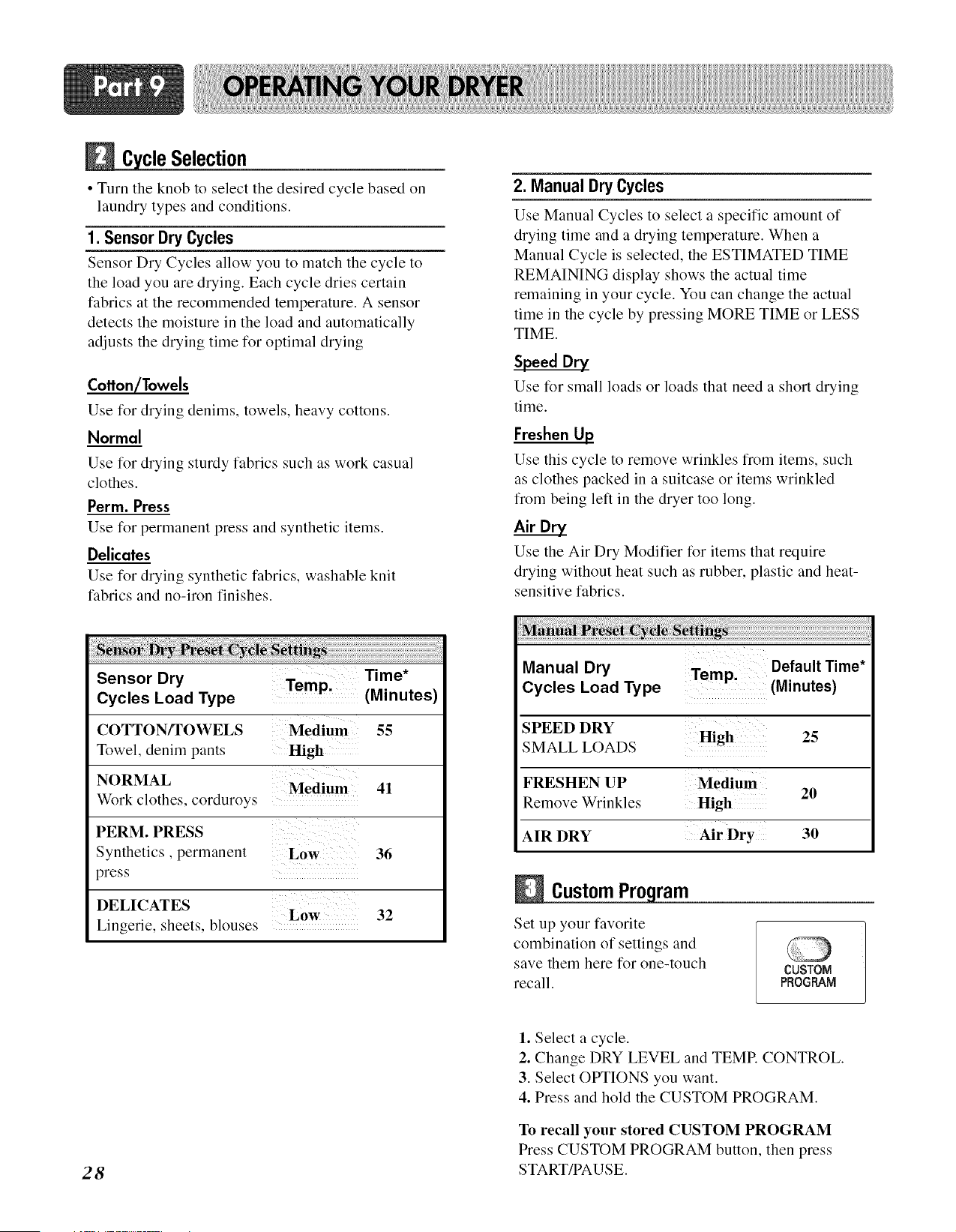
Custom ram
Set up your favorite
combination of settings and
save them here for one-touch
recall.
CUSTOM
PROGRAM
1. Select a cycle.
2. Change DRY LEVEL and TEMP. CONTROL.
3. Select OPTIONS you want.
4. Press and hold the CUSTOM PROGRAM.
To recall your stored CUSTOM PROGRAM
Press CUSTOM PROGRAM button, then press
START/PAUSE.
Time e Button
• Press MORE TIME or LESS
TIME until the desired drying
time is set.
MORE
TiME
LESS
TiME
Time change button is available only with Manual
Dry, Time Dry and Rack Dry programs.
LEDDisplay
1. CHECKFILTERREMINDER
The display will show CHECK FILTER when the
dryer is turned on as a reminder to check the filter.
It turns off when the START/PAUSE button is pressed.
• For better drying performance and safety, clean
lint fi!ter every sing!e use,
° Failure to follow these instructions can result in
death or fire.
2. Estimated Time Remaining
The display shows the estimated time remaining.
In addition to this, if the dryer has some problem, it
displays error messages.
3. CYCLECOMPLETIONINDICATOR
Shows how much of the current drying cycle has been
completed.
4. STATUS/CYCLEDISPLAY
This portion of the display shows the selected cycle,
operating status, and special messages. If a cycle has
special instructions, they will also be displayed in this
area.
Buttons
O CHILD LOCK
0 WRINKLE CARE
0 DAMP DRYBEEF
OPTION
PR_S_HeLDS_C
Te _r _41LDLC_K
1. Child Lock
Child Lock can be used to prevent
your children from changing options
on control panel while the dryer is
running.
When Child Lock is enabled, all the
buttons will be locked and
Child Lock glows.
To enable Child Lock, Press and hold OPTION for
3 seconds, A single beep tone is heard and Child
Lock is displayed on the status window.
To disable Child Lock, press and hold OPTION for
3 seconds again.
2. Wrinkle Care
This option helps to prevent wrinkles
in your laundry.
When you select the wrinkle free
option, the dryer will periodically
tumble for up to three hours after the
cycle has completed.
You can use this option in case you
can not remove laundry immediately
after drying is done.
3. Damp Dry Beep
When you select the damp dry beep option, a beep will
alert you when your load is approximately 80% dry.
This notice will allow you to remove lightweight items
that are dry or other items that you may wish to iron.
29
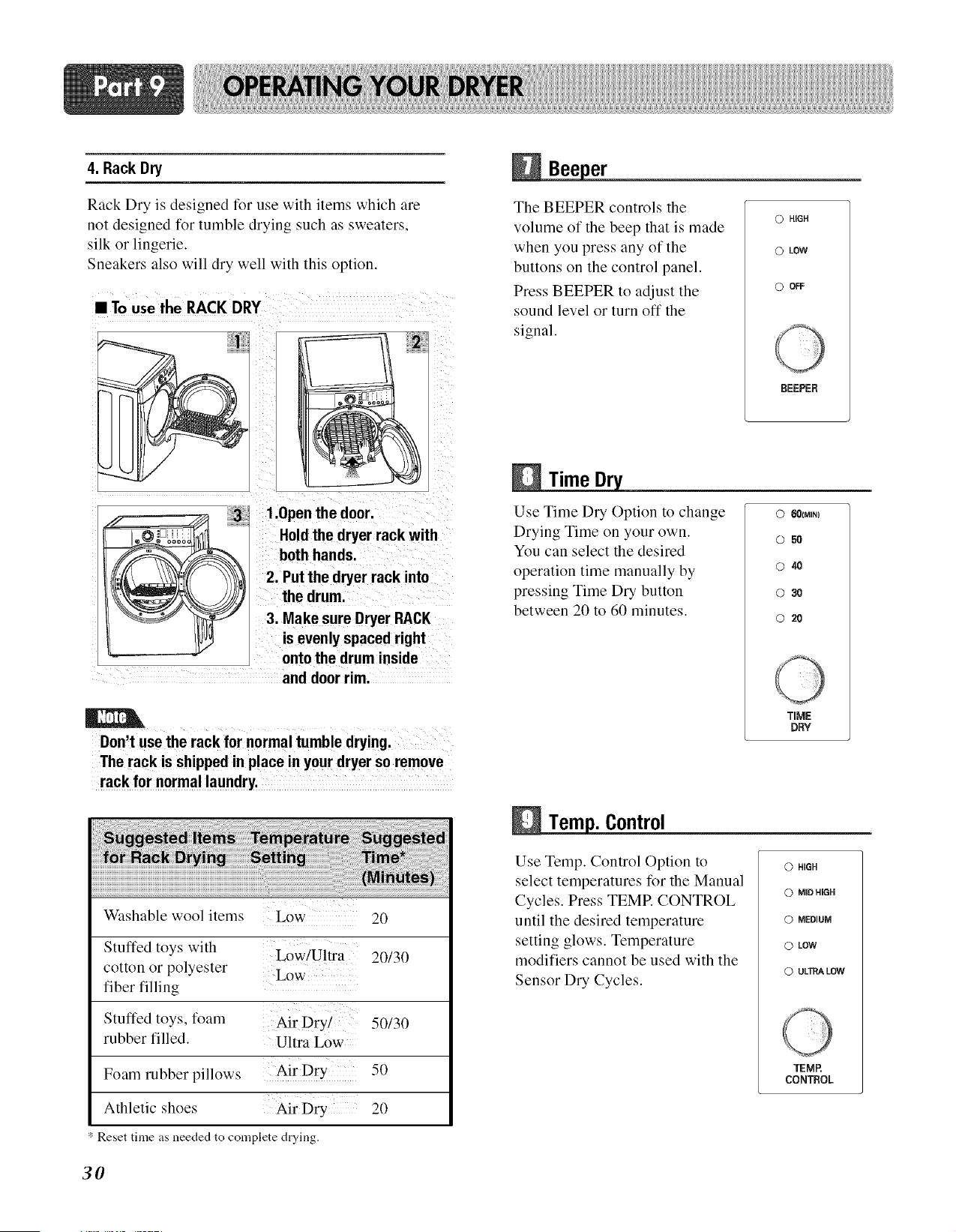
4. Rack Dry
Rack Dry is designed for use with items which are
not designed for tumble drying such as sweaters,
silk or lingerie.
Sneakers also will dry well with this option.
• To use the RACK DRY
3 1.0pen the door.
Hold the dryer rack with
both hands.
2. Put the dryer rack into
the drum.
3. Make sure Dryer RACK
is evenly spaced right
onto the drum inside
and door rim.
}er
The BEEPER controls the
volume of the beep that is made
when you press any of the
buttons on the control panel.
Press BEEPER to adjust the
sound level or turn off the
signal.
O HiGH
O LOW
0 o_
BEEPER
Time
Use Time Dry Option to change
Drying Time on your own.
You can select the desired
operation time manually by
pressing Time Dry button
between 20 to 60 minutes.
0 601MIN)
O50
o 4O
0 30
0 20
Don tuse the rack for normal tumble drying,
The rack is shipped in place in your dryer so remove
rack for normal laundry,
Washable wool items Low 20
Stuffed toys with
Low/Ultra 20/30
cotton or polyester Low"
fiber filling
Stuffed toys, foam Air Dry! 50/30
rubber filled. Ultra Low
Foam robber pillows
50
Athletic shoes Air Dry 20
Reset time as needed to complete drying.
i. Control
Use Temp. Control Option to
select temperatures for the Manual
Cycles. Press TEMP. CONTROL
until the desired temperature
setting glows. Temperature
modifiers cannot be used with the
Sensor Dry Cycles.
TIME
DRY
0 HiGH
0 MID HIGH
0 MEDIUM
0 LOW
0 ULTRALOW
30
TEMR
CONTROL
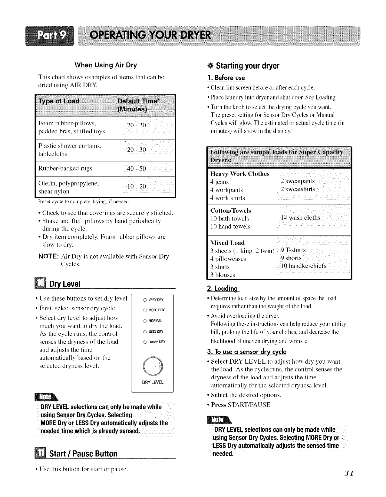
When Using Air Dry
This chart shows examples of items that can be
dried using AIR DRY.
Foam rubber-pillows,
padded bras, stuffed toys
Plastic shower curtains,
20-30
tablecloths
Rubber-backed rugs 40,50
Olefin, polypropylene,
shear nylon
10-20
Reset cycle to complete drying, if needed.
• Check to see that coverings are securely stitched.
• Shake and fluff pillows by hand periodically
during the cycle.
• Dry item completely. Foam rubber pillows are
slow to dry.
NOTE: Air Dry is not available with Sensor Dry
Cycles.
Level
• Use these buttons to set dry level
• First, select sensor dry cycle.
• Select dry level to adjust how
much you want to dry the load.
As the cycle runs, the control
senses the dryness of the load
and adjusts the time
automatically based on the
selected dryness level.
0 VERYDRY
O MORE DRY
O NORMAL
O LESS DRY
0 DAMP DRY
DRYLEVEL
DRY LEVELselections can only be made while
using Sensor Dry Cycles. Selecting
MOREDry or LESS Dry automatically adjusts the
Start / Pause Button
• Use this button for start or pause.
Startingyourdryer
1. Before use
• Clean lint screen before or after each cycle.
• Place laundry into dryer and shut door. See Loading.
• Turn the knob to select the drying cycle you want.
The preset setting for Sensor Dry Cycles or Manual
Cycles will glow. The estimated or actual cycle time un
minutes, will show in the display.
Heavy Work Clothes
4 jeans 2 sweatpants
4 workpants 2 sweatshirts
4 work shirts
Cotton/Towels
10 bath towels 14 wash cloths
10 hand towels
Mixed Load
3 sheets (l king, 2 twin)
4 pillowcases
3 shirts
3 blouses
9 T-shirts
9 shorts
10 handkerchiefs
2. Loading
• Determine load size by the amount of space the load
requires rather than the weight of the load.
• Avoid overloading the dryer.
Following these instructions can help reduce your utility
bill, prolong the life of your clothes, and decrease the
likelihood of uneven drying and wrinkle.
3. To use a sensor dry cycle
• Select DRY LEVEL to adjust how dry you want
the load. As the cycle runs, the control senses the
dryness of the load and adjusts the time
automatically for the selected dryness level.
• Select the desired options.
• Press START/PAUSE
DRYLEVEL Selections can only be made while
using Sensor Dry Cycles. Selecting MORE Dry or
LESS Dry automatically adjusts the sensed time
needed.
31
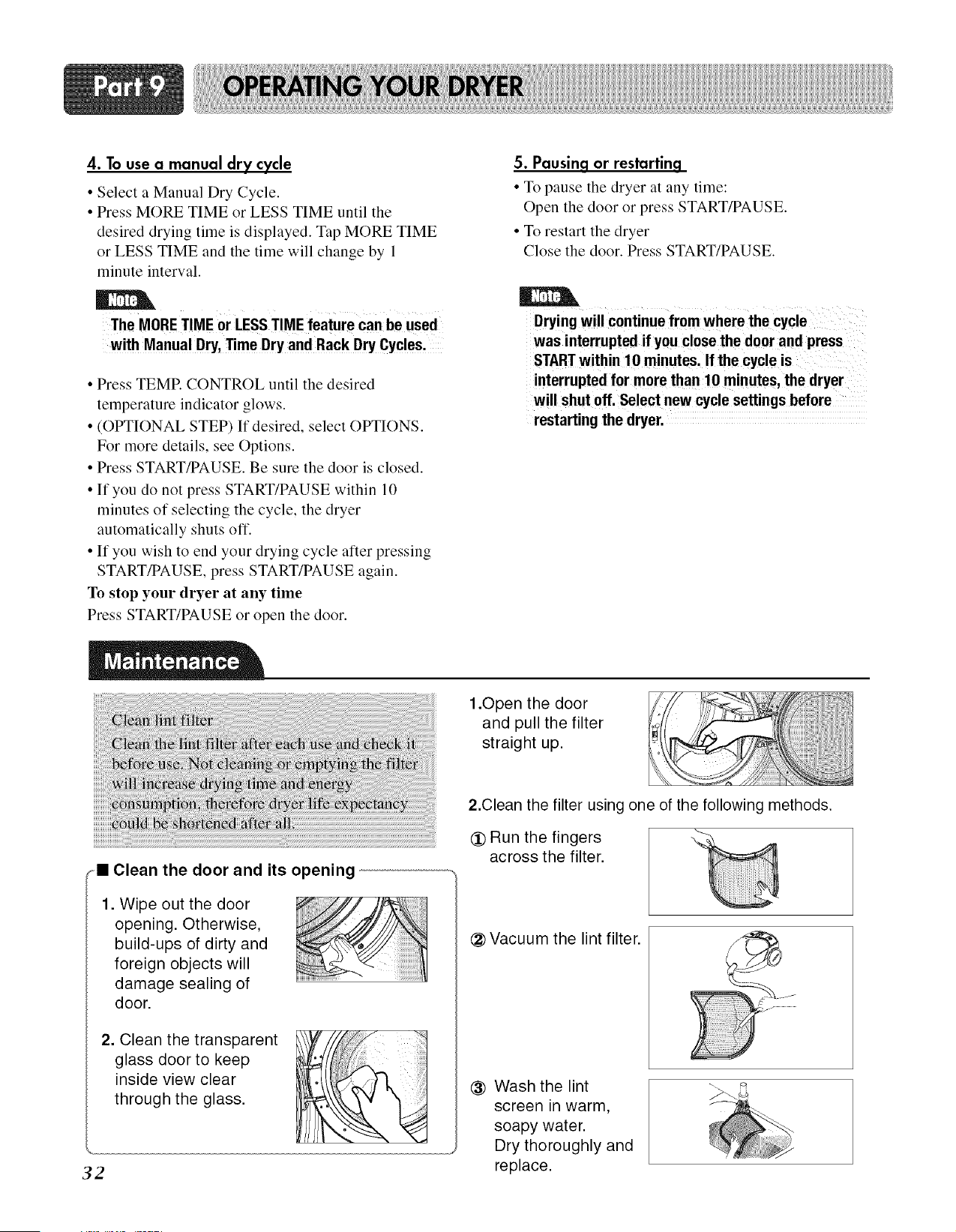
4. To use a manual dry cycle
• Select a Manual Dry Cycle.
• Press MORE TIME or LESS TIME until the
desired drying time is displayed. Tap MORE TIME
or LESS TIME and the time will change by 1
minute interval.
The MORETIME or LESS TIME feature can be used
with Manual Dry, Time Dry and Rack Dry Cycles.
• Press TEMR CONTROL until the desired
temperature indicator glows.
• (OPTIONAL STEP) If desired, select OPTIONS.
For more details, see Options.
• Press START/PAUSE. Be sure the door is closed.
• If you do not press START/PAUSE within 10
minutes of selecting the cycle, the dryer
automatically shuts off.
• If you wish to end your drying cycle after pressing
START/PAUSE, press START/PAUSE again.
To stop your dryer at any time
Press START/PAUSE or open the door.
5. Pausing or restarting
• To pause the dryer at any time:
Open the door or press START/PAUSE.
• To restart the dryer
Close the door. Press START/PAUSE.
Drying will continue from where the cycle
was interrupted if you close the door and press
STARTwithin 10 minutes. If the cycle is
interrupted for more than 10 minutes, the dryer
will shut off. Select new cycle settings before
restarting the dryer.
1.Open the door
and pull the filter
straight up.
32
_= Clean the door and its opening
1. Wipe out the door
opening. Otherwise,
build-ups of dirty and
foreign objects will
damage sealing of
door.
2. Clean the transparent
glass door to keep
inside view clear
through the glass.
2.Clean the filter using one of the following methods.
Run the fingers
across the filter.
(_ Vacuum the lint filter.
Wash the lint
screen in warm,
soapy water.
Dry thoroughly and
replace.
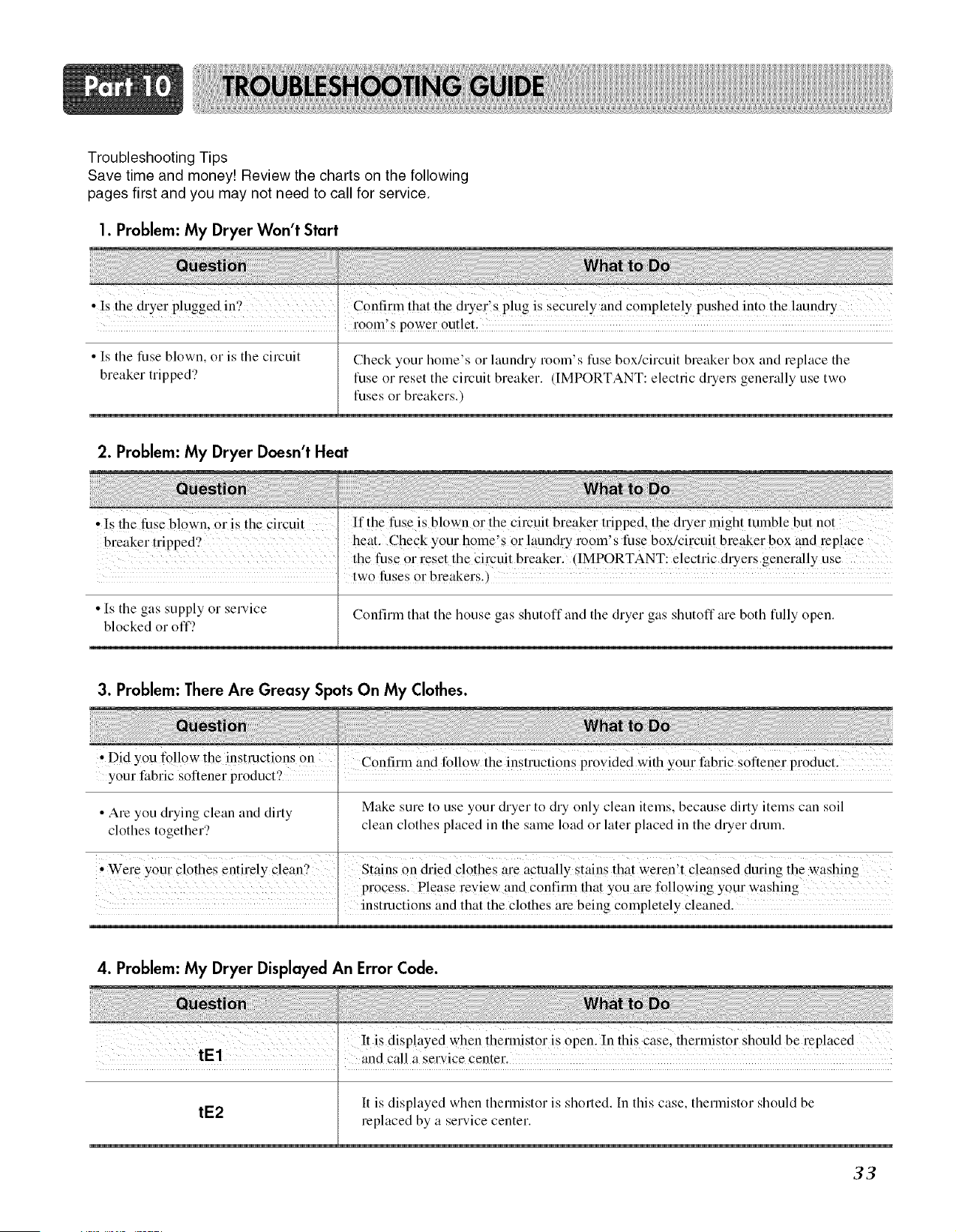
Troubleshooting Tips
Save time and money! Review the charts on the following
pages first and you may not need to call for service.
1. Problem:My Dryer Won't Start
• !s the dryer plugged m? C0nh!im that the dryer!s plug is securely and completely pushed into the laun&'y
I r00m'sp0wer0ut!et,
• Is tile fuse blown, or is the circuit Check your home's or laundry room's fuse box/circuit breaker box and replace tile
breaker tripped? fuse or reset the circuit breaker. (IMPORTANT: electric dryers generally use two
fuses or breakers.)
2. Problem:My Dryer Doesn't Heat
, Is the fuse blown, or is the circuit If the fuse is blown or the circuit breaker tripped, the diner might tumble but not
breaker tripped? heat• Check your home's 0r !auncky room's fuse box/cffcuit brewer box*and rePlace
the fuse 0r reset the Ci!vuit breaker. (IMPORTANT: electric dryers generally use
. tw0 _ses 0r breakers,)
• Is the gas supply or service Confirm that the house gas slmtoff and the dryer gas slmtoff are both tully open•
blocked or off'?
3. Problem: There Are Greasy Spots On My Clothes.
Did you follow the instructions On
• Confirm and follow the instmcti0ns provided With Your t:abric softener pr0ducL
your l:abric softener product?
• Are you drying clean and dirty Make sure to use your dryer to dry only clean items, because dirty items can soil
clothes together? clean clothes placed in the same load or later placed in the dryer drum.
• Q 1
iWer e your Clothes entirely C!ean` Stains On &ied clothes are actually stains that weren t cleansed during the washing
process. Please revie w and Confinn that YOUare following your washing
• instructions and that the clothes are being Completely cleaned.
4. Problem:My Dryer Displayed An Error Code.
It is displayed when thennist0r is OPen. !n this case, thermistor should be replaced
and call a service center.
It is displayed when therlnistor is shorted. In this case, therlnistor should be
tE2
replaced by a service center.
33
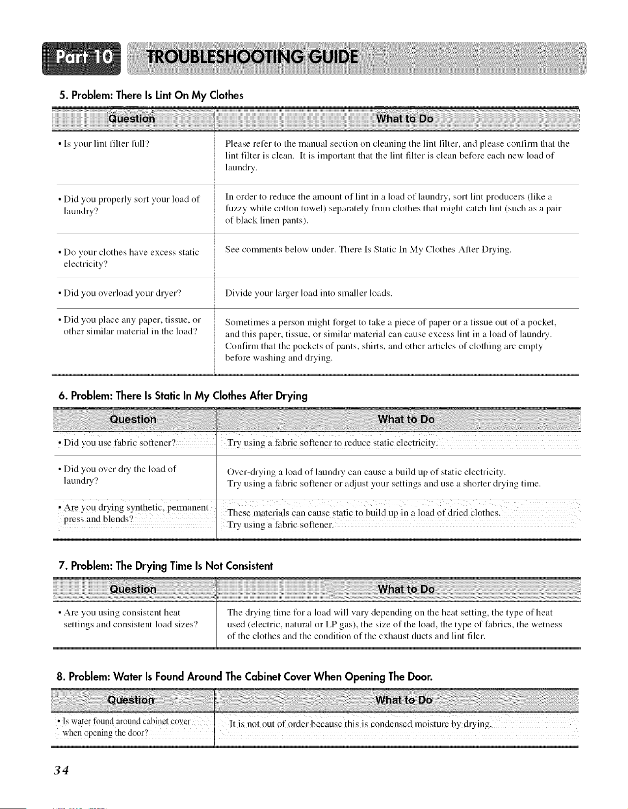
5. Problem:There Is LintOn My Clothes
• Is your lint filter lull'? Please refer to the manual section on cleaning the lint filter, and please confirm that the
lint filter is clean. It is important that the lint filter is clean before each new load of
laundry.
• Did you properly sort your load of In order to reduce the amount of lint in a load of laundry, sort lint producers (like a
laundry? fuzzy white cotton towel) separately fioln clothes that might catch lint (such as a pair
of black linen pants).
• Do your clothes have excess static See comments below under. There Is Static In My Clothes After Drying.
electricity'?
• Did you overload your dryer? Divide your larger load into smaller loads.
• Did you place any paper, tissue, or
other similar material in the load'?
Sometimes a person might forget to take a piece of paper or a tissue out of a pocket,
and this paper, tissue, or silnilar material can cause excess lint in a load of laundry.
Confirm that the pockets of pants, shirts, and other articles of clothing are elnpty
before washing and drying.
6. Problem: There Is Static In My Clothes After Drying
i_ _ i i i I _I i i ii
• 9
Did YOUuse fabric so_ener, Try using a t:abric s°ftener t ° reduce static electricity:
• Did you over dry the load of Over-drying a load of laundry can cause a build up of static electricity.
laundry? Try using a fabric softener or adjust your settings and use a shorter drying time.
• Are Y0u &:ying synthetic; permanent
press and blends `? These materials Can Cause static to build up in a load Of dried Clothes.
Try Using a t:abric Softener.
7. Problem: The Drying Time Is Not Consistent
• Are you using consistent heat
settings and consistent load sizes'?
The drying time for a load will vary depending on the heat setting, the type of heat
used (electric, natural or LP gas), the size of the load, the type of fabrics, the wetness
of the clothes and the condition of the exhaust ducts and lint filer.
8. Problem: Water Is Found Around The Cabinet Cover When Opening The Door.
• Is water found around cabinet cover
when opening the door'?
It is not Out of Orderbecause this is Condensed moisture by drying.
34
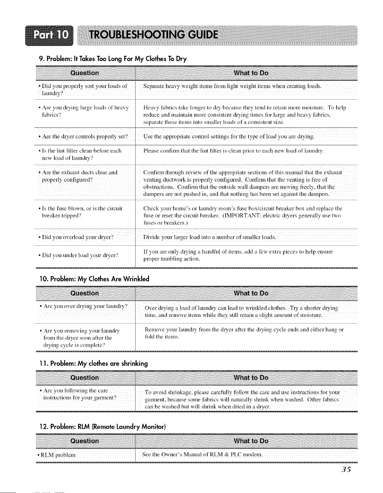
9. Problem: It TakesToo Long For My ClothesTo Dry
• Did you properly ior t You!I loads Of separate heaYy weight items from light _eight items when C!_eatingloads.
launch'y? .
• Are you drying hu'ge loads of heavy Heavy fabrics take longer to dry because they tend to retain more moisture. To help
fabrics? reduce and maintain more consistent drying times for large and heavy fabrics,
separate these items into smaller loads of a consistent size.
, Are the dryer controls properly set2 Use the appropriate control settings for the type of load you are drying.
• Is the lint filter clean before each Please confirm that the lint filter is clean prior to each new load of laundry.
new load of laundry?
Are the exhaust ducts clear and Confirm through reyiew 0f the appropt;iate Sections Of this manua! that the exhaust
pr0per!y c0nfigured ? venting ductwork is properly Configured. Confirm that the Yenting is h7ee of
Obstructions. Confirm that the Outside wall dampers me moving fl'eely, that the
' dampers m-enot pushed in, and that nothing has been set against the dampers.
• Is the fuse blown, or is the circuit Check your home's or laundry room's fuse box/circuit breaker box and replace the
breaker tripped? fuse or reset the circuit breaker. (IMPORTANT: electric dryers generally use two
fuses or breakers.)
* Did you overload your &:yer? Divide your larger load into a number of slnaller loads.
If you are only drying a handful of items, add a few extra pieces to help ensure
• Did you under load your dryer? proper tumbling action.
10. Problem: My ClothesAre Wrinkled
,Are you Over drying your laundry? _ -- 7 .... -
Over drying a !0adOf!aun&'y Can !ead to Wrinkled C!othes, Try a Sho,_er &.ying
time, and remove items while they still retain a slight amount of moisture.
• Are you removing your laundry Remove your laundry flom the dryer ariel the drying cycle ends and either hang or
flom the dryer soon after the fold the items.
drying cycle is complete?
11. Problem: My clothesare shrinking
• Are you following the Care
TOavoid Shrinkage, please carefully follow the Care and use instructions for Y0u!:
o
instructions to!7your garment, garment ' becaus e some fabrics wi!! naturally shrink when washed, Other fabrics
can be washed but will shrink when dried in a dryer.
12. Problem: RLM (RemoteLaundry Monitor)
, RLM problem See the Owner's Manual ofRLM & PLC modem.
3_

Your LG Dryer will be will repaired or replaced, at LG's option, if it proves to be defective in material or
workmanship under normal use, during the warranty period ("Warranty Period") set forth below, effective
from the date ("Date of Purchase") of original consumer purchase of the product. This limited warranty is
good only to the original purchaser of the product and effective only when used in the United States,
including Alaska, Hawaii, and U.S. Territories.
35
WARRANTY PERIOD:
LABOR: One Year from the Date of Purchase.
PARTS: One Year from the Date of Purchase.
Replacement Units and Repair Parts may be new or
factory remanufactured.
Replacement Units and Repair Parts are warranted
for the remaining portion of the original unit's
warranty period.
HOW SERVICE IS HANDLED:
In=Home Service: Please retain dealer's dated
bill of sale or delivery ticket as evidence of the
Date of Purchase for proof of warranty, and
submit a copy of the bill of sale to the service
person at the time warranty service is provided.
Please call t =800=243=0000 and choose the
appropriate option to locate your nearest LG
Authorized Service Center, (Phones are
answered 24 hours a day, 365 days per year.)
Or visit our website at: http://www.lgservice.com
THIS WARRANTY IS IN LIEU OF ANY OTHER WARRANTY, EXPRESS OR IMPLIED, INCLUDING
WITHOUT LIMITATION, ANY WARRANTY OF MERCHANTABILITY OR FITNESS FOR A
PARTICULAR PURPOSE. TO THE EXTENT ANY IMPLIED WARRANTY IS REQUIRED BY LAW, IT IS
LIMITED IN DURATION TO THE EXPRESS WARRANTY PERIOD ABOVE. NEITHER THE
MANUFACTURER NOR ITS U.S. DISTRIBUTOR SHALL BE LIABLE FOR ANY INCIDENTAL,
CONSEQUENTIAL, INDIRECT, SPECIAL, OR PUNITIVE DAMAGES OF ANY NATURE, INCLUDING
WITHOUT LIMITATION, LOST REVENUES OR PROFITS, OR ANY OTHER DAMAGE WHETHER
BASED IN CONTRACT, TORT, OR OTHERWISE. Some states do not allow the exclusion or limitation of
incidental or consequential damages or limitations on how long an implied warranty lasts, so the above
exclusion or limitation may not apply to you. This warranty gives you specific legal rights and you may
also have other rights that vary from state to state.
THIS LIMITED WARRANTY DOES NOT APPLY TO:
Service trips to your home to deliver, pick up, and/or install the product, instruct, or replace house fuses or
correct wiring, or correction of unauthorized repairs.
Damages or operating problems that result from misuse, abuse, operation outside environmental
specifications or contrary to the requirements of precautions in the Operating Guide, accident, vermin, fire,
flood, improper installation, acts of God, unauthorized modification or alteration, incorrect electrical current or
voltage, or commercial use, or use for other than intended purpose.
The cost of repair or replacement under these excluded circumstances shall be borne by the consumer.
CUSTOMER INTERACTIVE CENTER NUMBERS
To obtain Customer Assistance, Product Infor=
marion, or Dealer or Authorized Service Center
location:
TO CONTACT LG ELECTRONICS BY MAIL:
LG Customer Interactive Center
P. O. Box 240007
201 James Record Road
Huntsville, Alabama 35824
ATTN: ClC
Call 1 =800=243=0000 (24 hours a day, 365 days per
year) and select the appropriate option from the menu.
Or visit our website at: http:llwww.lgservice,com
1-800-243-0000
para el Servicio LG (Atenci6n al CJiente) 24 horas al dia, 7 dias a la semana
SecadoradeEl_ctricay Gas
DLE3733W / DLG3744W
DLE3733S / DLG3744S
Secadora LG. Por favor lea su
ue
una instalaci6n segura,
el modelo y nOmero de serie y
referendas.
sitio web http//us.lge.com
DESEMPEI O EXTRAORDINARIO
Sin mencJonar su incomparable gran capacidad, puede beneficJarse por su Eficiencia en
tiempo, operacion silenciosa y su sistema de ahorro de energla
CUVE EN ACIER/ . DOUBLE ENDUIT
Enduit avec une couche de metal enduit et une autre couche de polymere afin d'assurer la
durabilite et une Iongue vie.
DISEI IOARTOiSTEO
El moderno Dise_o del Panel Frontal y su gran puerta de cristal hacen que su hogar se vea con
m&s estilo.
CUIDADO DIGITAL
El calentador controla las temperaturas Multi-niveles cuidando mejor sus
prendas m&s preciadas
USO SENCILLO
Una amplJa seleccJon de funciones de uso amigables sJempre Io haran sentirse mas confortable
con las operaciones de su secadora.
Su secadora le proporciona la posibilidad de programar acciones de secado por sensor o por tiempo.
Secado por sensor
La secadora detectarA automAticamente la humedad de la colada y determinar& el tiempo de funcionamiento necesario
bas&ndose en el nivel de sequedad de la carga y el programa seleccionado. En ocasiones, podra observar un incremento
o disminuci6n repentinos del tiempo de operaci6n. Si esto ocurriera, ser#, debido a que el sensor detecta la humedad de
la colada dentro de un perfodo de tiempo determinado. Un cambio repentino en el tiempo de operaci6n no significa un
real funcionamiento.
Secado por tiempo
Significa que puede programar el tiempo de operaci6n manualmente para completar el secado. Altemativamente, puede
usar esta funci6n para secar la ropa si las prendas aun estan humedas pese a haber terminado un ciclo de secado.
El secado pot tiempo es mas efectivo cuando tenga prendas pesadas u objetos voluminosos como sAbanas de camas
tamaRo superdoble o ropa de trabajo gruesa.
J
PARTE 1. ESPECINCACIONES ............................................................................................................................................................................................................. 3
PARTE 2. GARANT|A E INSTRUCCIONES DE SEGURIDAD EMPORTANTES ................................................................................................................................... 4
PARTE 3. PASOS INECIALES PARA LA ENSTALAC_ON DE SU SECADORA ................................................................................................................................... 11
PARTE 4. INSTALACION DE ACCESORIOS ....................................................................................................................................................................................... 17
PARTE 5. REQUERIMIENTOS ELE_CTRICOS PARA SECADORA ELE_CTRICAS ............................................................................................................................. 19
PARTE 6. REQUER_MEENTOS ELECTRICOS PARA SECADORAS A GAS ...................................................................................................................................... 23
PARTE 7. REQUERIMEENTOS E INSTRUCCIONES SOBRE EL GAS ............................................................................................................................................... 24
PARTE 8. REQUERIMIENTOS Y MANTENIMIENTO SOBRE EL ESCAPE ........................................................................................................................................ 25
PARTE 9. USANDO SU SECADORA ................................................................................................................................................................................................... 27
PARTE 10. GU{A PARA LA SOLUCK)N DE PROBLEMAS ................................................................................................................................................................ 33
GARANT|A LIMITADA DE LA SECADORA LG ................................................................................................................................................................................... 36
2
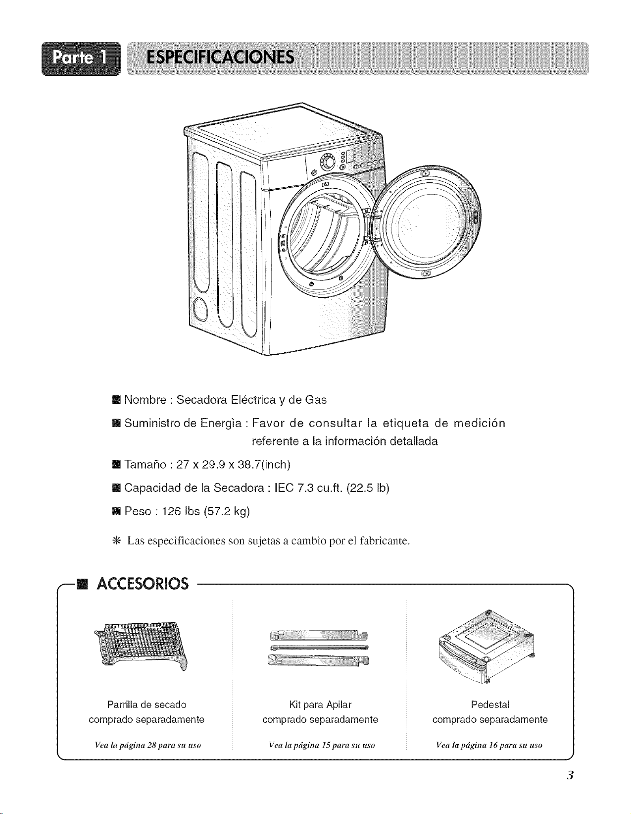
m Nombre : Secadora Electrica y de Gas
m Suministro de Ene@a : Favor de consultar la etiqueta de medici6n
referente a la informaci6n detallada
m Tama5o : 27 x 29.9 x 38.7(inch)
m Capacidad de la Secadora : IEC 7.3 cu.ft. (22.5 Ib)
m Peso : 126 Ibs (57.2 kg)
÷ Las especificaciones son sujetas a cambio pot el fabricante.
ACCESORIOS
Parrilla de secado
comprado separadamente
Vea la pdgina 28 para stt use
Kit para Apilar
comprado separadamente
Vea la pdgina 15 para sll ttso
Pedestal
comprado separadamente
Vea la pdgina 16 para s'tt use
J
3
BOSQUEDA DE ASISTENCIA SOBRE LA GARANTJA
Encontrarg_ la garantia de su secadora en la parte final de este manual. El servicio de
garantia esta disponible contactando con su Centro de Servicio LG mg_spr6ximo. Si este
producto se instala y se opera siguiendo las instrucciones de este manual, LG repararA o
recambiarA cualquier pieza defectuosa en material o mano de obra a Io largo del periodo
cubierto por la garanfia, comenzando desde el dfa de compra.
,_ ADV_'R"Flg'NC|A=_ Para su seguridad, debe seguir las recomendaciones de
este manual. Para reducir el riesgo de incendio o explosi6n, o ehoque electrico, o para
prevenir dafios a la propiedad, lesiones personales, o muerte cuando use su artefacto, siga
las precauciones basicas, incluyendo las siguientes.
Restricci6n de [a Garantia : Si la secadora es utilizada para otto prop6sito que no sea el uso
familiar privado, toda cobertura de la garantfa es efectiva por s61o 90 dfas.
Necesitarfi el nfimero de modeloo y de serie completo al solicitar la garantfa de servicio. Es necesaria
la prueba de la compra (ticket o recibo).
Utilice el siguiente espacio para anotar el ndmero de modelo y de serie de su nueva secadora LG.
Modelo Ndmero
Ndmero de Serie
Fecha de Adquisici6n
_ Tenga a mano su ticket de compra por comodidad al contactar con el servicio de atenci6n al
cliente.
LEATODASLAS INSTRUCCIONESANTESDEUTILIZAR
ADVERTENCIA Por su seguridad,la informaci6ndeestemanualdebeseguirseparareduciral minimoel riesgode
incendioo explosibn,descargasel6ctricas,o paraevitarda_osa lapropiedad,lesionespersonales
Su seguridad y ia de otros es muy importante,
Hemos incluido muchos mensajes de seguridad importantes en este manual yen el aparato.
Lea y cumpla en todos los casos estos mensajes de seguridad.
Este es el simbolo de alerta de seguridad.
Este simbolo le alerta de los peligros que podrian matarle a usted o a otros.
Todos los mensajes de seguridad aparecer_tn despu_s del sfmbolo de alerta y la palabra
"PELIGRO" o "ADVERTENCIA".
Estas palabras significan:
Xk PELIGRO
Sino curnplecon las instruccionesde inrnediatopuedecotter peligrode rnuerteo de lesionesgraves,
A ADVERTENCJA Nocumplirias instruccionespuedeocasionarleia rnuerteo iesionesgraves,!!
Todos los mensajes de seguridad le informarAn de peligros potenciales, c6mo reducir las
posibilidades de riesgo, y le informaran que pasarfa si no se siguen las instrucciones.
PRECAUCJONESBASJCASDE SEGURJDAD.
A ADVERTENCIA Para reducirel riesgode incendio,descargael6ctrica o da_osa usuariosdelaparato,
siga Jasprecaucionesb_sicas, incJuidaslas siguientes:
oLeatodaslas instruccionesantesde usarla secadora.
, Antesdeusar,la secadoradebeinstalarsecorrectamentesegOn
Iodescritoenestemanual.
, Nointroduzcaarficulosexpuestosa aceitesdecocinaensu
secadora.Losarficuloscontaminadosconaceitesdecocina
puedencontribuira unareacci6nqufmicaquepodrfa.provocar
unacargay ocasionarun incendio.Nosequearficulosque
previamentesehayanlimpiado,lavado,empapado,o sehayan
manchadocongasolina,disolventesdela limpiezaenseco,
otrassustanciasinflamableso explosivaspuestoqueemiten
vaporesquepodrfanprovocarignici6no estallar.
, Notoquela secadorasi eltamborseest,.moviendo.
°Noreparenisubstituyaningunapiezadelasecadoray nointente
realizartareasdemantenimientoamenosqueserecomiende
especificamenteenestaGuiadecuidadoy Usoo enlas
instruccionespublicadasdereparaci6npotpartedelusuarioque
ustedentiendayestecapacitadoparaIlevara cabo.
, Notratedeforzarloscontroles.
, Antesdesacardeservicioa lasecadorao deshacersedeella,
quitelapuertadelcompartimientodesecado..
* Nopermitaqueotrosni_osjueguencercadelasecadora.
Esnecesariosupervisarestrechamentea losniSoscuandola
secadorase utilicecercadeellos.
, Noutilicesuavizadoreso productosparaeliminarlaest_ttica
exceptocuandosearecomendadoporel fabricantedel
suavizadoro delproducto.
* Noutilicecalorparasecararticulosquecontengancauchode
espumao materialesdetexturasimilaralcaucho.
* Mantengael _treacircundantea laaberturadelescapey delos
alrededoreslibredela acumulaci6ndela pelusa,delpolvo,y
suciedad.
* Personaldeserviciocualificadodebeiimpiarel interiordela
secadoray delescapeperi6dicamente.
* Noinstalenialmaceneia secadoraenuniugarenelcualquede
expuestaa lascondicionesatmosfericas.
*Notoquelasecadoramientraslaspiezasseestenmoviendo.
* Compruebesiempreel interiordelasecadoraparaverificarsi
hayobjetosextra_os.
* Limpiela pelusadela pantallaanteso despuesdecadacarga.
GUARDEESTASiNSTRUCCIONE$
LEATODAS[.AS IHSTRUCCJONESANTESDEUTILiZAR
A ADVERTENCJA Porsuseguridad,la informaci6ndeestemanuaJdebeseguirseparareducira]m!nimoel riesgode
incendiooexplosibn,descargasel6ctricas;o paraevitarda_osa lapropiedad,lesionespersonales
* No guarde ni use gasolina ni otros vapores
infiamables ni liquidos en las cercanias de
este u otro electrodom6sfico.
* La instalaci6n y el servicio se deben ser
Ilevadas a cabo por parte de un instalador
cualificado, agencia de servicio, o el
suministrador del servicio de gas.
PRECAUCIONESBASICASDESEGURIDAD.
siga las precauciones b_sicas, incluidas las siguientes:
INSTRUCCIONES PARA LA TOiVlA A
TIERRA
Este aparato debe tener una toma a tierra
adecuada. En caso de un mal
funcionamiento o averia, disponer de toma
a tierra reducirA el riesgo de descargas
electricas proporcionando una trayectoria de
menor resistencia para la corriente electrica.
Este aparato debe ir equipado con un cable
que tenga un conductor de toma a tierra del
equipo y un enchufe con toma a tierra.
El enchufe debe ir conectado en un
tomacorriente apropiado debidamente
instalado y con una toma a tierra que
cumpla todos los c6digos y ordenanzas
locales.
ADVERTENCIA - La conexi6n incorrecta del
conductor de toma a tierra del equipo puede
dar lugar a un riesgo de descarga electrica.
Compruebe con un electricista cualificado o un
personal del servicio si duda de si el aparato
dispone de una toma a tierra correcta.
No modifique el enchufe proporcionado con el
aparato.
Si no cabe el enchufe en el tomacorriente,
solicite a un electricista cualificado la
instalaci6n de un enchufe apropiado.
Este aparato debe conectarse a un metal con
toma a tierra, sistema permanente de
cableado o debe tenderse un conductor de
toma a tierra del equipo con conductores del
circuito y conectarse al terminal de toma a
tierra del equipo o hacia el aparato.

LEATODASLASINSTRUCCIONESANTESDEUTILIZAR
XIL ADVERTENCIA Porsuseguridad,lainformaci6ndeestemanualdebeseguirseparareduciral minimoel riesgode
incendiooexplosi6n,descargasel6ctricas,oparaevitarda_osa lapropiedad,lesionespersonales
QU¢:A HACERSI HUELEGAS
utilizar el aparato, siga las precauciones b_sicas, incluidas las siguientes:
1. No intente encender un f6sforo ni un
cigarrillo, ni ponga en marcha ningt3n
aparato de gas o electrico.
2. No toque ningt3n interruptor el_ctricos.
No utilice ningt3n tel_fono de su edificio.
3. Despeje la sala, el edificio, o el Area de
todos los inquilinos.
4. Llame inmediatamente a su suministrador
de servicio de gas utilizando el tel_fono de
un vecino. Siga el tel_fono del
suministrador del servicio de gas. Siga las
instrucciones del suministrador del servicio
de gas.
5. Si no puede ponerse en contacto con su
suministrador del servicio de gas, Ilame al
cuerpo de bomberos.
LEYENVIGORSOBRELATOXICIDADY POTABILIDADDELAGUAEN CALIFORNIA
utilizarel aparato,sigalas precaucionesbbsicas,incluidaslas siguientes:
Esta ley requiere al gobernador de California publicar una lista de las sustancias
cancerfgenas conocidas al Estado, defectos de nacimiento, u otros dafios al sistema
reproductivo y obliga alas empresas a advertir a sus clientes de la posible exposici6n a tales
sustancias.
Los aparatos que usen gas pueden causar exposiciones de pequefia importancia con cuatro
de estas sustancias: benceno, di6xido de carbono, formaldehido, y holl[n, causadas
primordialmente pot la combusti6n incompleta del gas natural o de combustibles del LP
Las secadoras con ajustes correctos reducir&n al minimo la combusti6n incompleta.
La exposici6n a estas sustancias puede set reducida al minimo at3n m&s mediante la
ventilaci6n correcta de la secadora al aire libre.
7
LEATODASLASINSTRUCCIONESANTESDEUTILIZAR
ADVERTENC|A P0rsuseguridad,lainf0rmaci6ndeestemanualdebeseguirseparareduciralminim0elriesg0de
incendi00 expl0si6n,descargasel6ctricas,0 paraevitarda_0sa lapr0piedad,lesi0nespers0nales
0p6rdidadevidahumana.
INSTRUCCIONDESEGURIDADPARALA INSTALACION
aparato, sigalas precaucionesbbsicas,incluidaslassiguientes:
• La secadora, con toma a tierra adecuada,
debe cumplir con todos los cbdigos y
ordenanzas en vigor. Siga los detalles de
las instrucciones de instalacibn.
Puede ocurrir una descarga el_ctrica si la
secadora no dispone de una toma a tierra
correcta.
• Antes de usar, la secadora debe
instalarse correctamente seg_n Io
descrito en este manual.
Puede ocurrir una descarga el_ctrica si la
secadora no dispone de una toma a tierra
correcta.
• Instale y almacene la secadora donde no •
quede expuesta alas temperaturas bajo
cero ni a la intemperie.
Todas las reparaciones y el mantenimiento
deben set realizadas pot un t_cnico de
servicio autorizado excepto all_ donde esta •
Gufa del propietario Io recomiende de otra
manera. Utilice solamente piezas
autorizadas de f&brica. No seguir esta
advertencia puede causar lesiones serias,
un incendio, un descarga electrica o incluso
la muerte.
No instale la lavadora en espacios
h_medos para reducir el riesgo de
descarga el_ctrica.
No seguir esta advertencia puede causar
lesiones serias, un incendio, un descarga
electrica o incluso la muerte.
Conecte a un circuito de la potencia
nominal correcta, protegido, y con la
potencia adecuada para evitar una
sobrecarga el_ctrica.
Un circuito incorrecto puede derretirse,
creando una descarga el_ctrica y/o riesgo
de incendios.
Quite todos los articulos del embalaje y
elimine todos los materiales de envio
correctamente
No hacerlo podrfa ocasionar la muerte, una
explosi6n o quemaduras.
Coloque la secadora por Io menos 18
pulgadas sobre el piso en el caso de una
instalaci6n en un garaje.
No hacerlo podr_a ocasionar la muerte, una
explosi6n o quemaduras.
8
LEATODASLASINSTRUCCIONESANTESDEUTILIZAR
X]_ ADVERTENCIA Por suseguridad,lainformaci6nde estemanualdebeseguirseparareduciral minimoelriesgode
incendiooexplosi6n,descargasel6ctricas,oparaevitarda_osa lapropiedad,lesionespersonales
INSTRUCCIONDESEGURIDADPARALA INSTALACION(CONT.)
Escape/Conducto: • El conducto no se entrega con la secadora.
• Las secadoras de gas SE DEBEN conducir
su escape al exterior.
No seguir estas instrucciones puede dar lugar
a un incendio o incluso la muerte.
• El dispositivo de escape de la secadora se
debe canalizarse al exterior de la vivienda.
Si la secadora no conduce su escape al
exterior, se expulsara.n _.rea al _.rea del
lavadero algo de pelusa fina y grandes
cantidades de humedad. Una acumulaci6n de
pelusa en cualquier _.rea del hogar puede
crear un riesgo a la salud y de incendios.
• Utilice solamente un conducto de metal
rigido o metal flexible de 4 pulgadas con un
di_metro en el interior del armario de la
secadora o para conducir el escape al
exterior.
El uso de pl_.stico o de otro conducto
combustible puede causar un incendio.
La existencia de orificios en el conducto puede
causar un incendio si queda atrapado en
funcionamiento o durante la instalaci6n
Usted es el responsable de instalar el
conducto necesario en el lugar de
instalacibn. La tapa del extremo debe
disponer de abisagradores con
amortiguacibn para evitar corrientes de aire
a contraviento cuando la secadora est_
parada.
No seguir estas instrucciones puede dar lugar
a un incendio o incluso la muerte.
El conducto del escape debe tener 4
pulgadas (10 centimetros) de di_metro sin
obstrucciones.
El conducto del escape debe ser Io mas
corto posible. Cercibrese de limpiar
cualquier viejo conducto antes de instalar
su nueva secadora.
No seguir estas instrucciones puede dar lugar
a un incendio o incluso la muerte.
• Se recomienda el uso entre la secadora y
la pared de un conducto rigido o
semirrigido. En especial, en aquellas
instalaciones en las que sea imposible
realizar una conexibn siguiendo las
recomendaciones antedichas, puede
utilizarse un conducto de transici6n
metal flexible de norma UL entre la
secadora y la conexi6n de la pared
solamente. El uso de este tipo de
conducto afectar_ al tiempo de secado.
NO utilice los tornillos del metal de hoja
u otros amarres que se extienden al
conducto puesto que podrian recoger
pelusa y reducir la eficiencia del
dispositivo de escape. Asegure todas las
juntas con cinta para conductos.
Para m_s detalles, siga las instrucciones
de instalacibn.
No seguir estas instrucciones puede dar
lugar a un incendio o incluso la muerte.
No seguir estas instrucciones puede dar
lugar a un incendio o incluso la muerte.
9
LEATODASLASINSTRUCCIONESANTESDEUTILIZAR
ADVERTENC|A P0rsu seguridad,la inf0rmaci6nde estemanualdebeseguirseparareduciral minim0el riesg0de
incendi00 expl0si6n,descargasel6ctricas,0 paraevitarda_0sa lapr0piedad,lesi0nespers0nales
INSTRUCCIONDESEGURIDADPARALACONEXIONDE ELECTRICIDAD
X_ ADVERTENCIA Para reducir el riesgo de incendio, descarga el_ctrica o da_os a usuarios del
I0
• Bajo ninguna circunstancia deber_ cortar
o eliminar la tercera patilla (de toma a
tierra) del cable de alimentaci6n.
Para evitar lesiones personales o daSos a la
secadora, el cable de corriente el_ctrica se
ir conectado debidamente y contar con una
toma a tierra adecuada.
• Por su seguridad personal, esta
secadora ha de tener una toma a tierra
adecuada.
No hacerlo podria ocasionar descargas
el_ctricas o lesiones.
• Consulte las instrucciones de instalacibn
de este manual para los requisitos
el_ctricos especificos de su modelo.
No seguir estas instrucciones puede ser
causa de una descarga el_ctrica y/o un
riesgo de incendios.
• Esta secadora ha de ir conectada a un
tomacorriente con una toma a tierra
adecuada
Puede ocurrir una descarga el_ctrica si la
secadora no dispone de una toma a tierra
correcta.
• Solicite que un electricista cualificado
compruebe la toma a la pared y el
circuito para asegurarse de que la toma a
tierra estb correctamente realizada.
Esto evitara peligros de descargas y asegurara la
estabilidad durante el funcionamiento.
La secadora siempre ha de ir conectada
a su propio tomacorriente el_ctrico
individual con una potencia nominal que
coincida con la de la placa.
Una instalaci6n asi proporciona el mejor
rendimiento y tambi_n evita la sobrecarga
de los circuitos de cables dom_sticos, Io
que podria provocar riesgo de incendio
debido a unos cables recalentados.
• Nunca desenchufe su secadora estirando
del cable de alimentaci6n.
Sujete siempre firmemente el enchufe y
s&quelo de la toma sin agitarlo de lado a
lado.
El cable de alimentaci6n puede cortarse
como consecuencia de un movimiento del
nQcleo, provocando una descarga el_ctrica.
Repare o cambie de inmediato todos los
cables de servicio el_ctrico que se hayan
pelado o dahado. No utilice cables que
muestren grietas o dahos por abrasi6n
por su extensi6n o en cualquier extremo.
Un circuito incorrecto puede derretirse,
creando una descarga el_ctrica y/o riesgo
de incendios.
• AI instalar o mover la secadora, tenga
cuidado de no pisar, machacar, o dahar
el cable el_ctrico.
Esto evitar& lesiones y daSos a la secadora
pot fuego y descargas electricas.
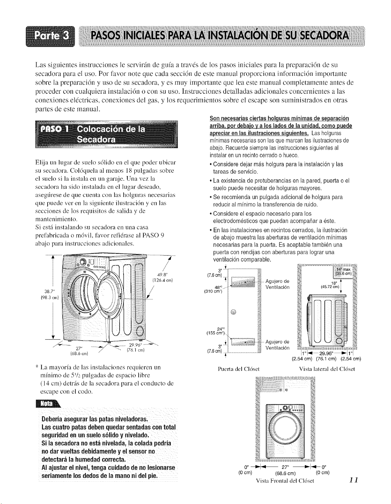
Las siguientes instrucciones le servirfin de gufa a travds de los pasos iniciales para la preparaci6n de su
secadora para el uso. Por favor note que cada secci6n de este manual proporciona informaci6n importante
sobre la preparaci6n y uso de su secadora, y es muy importante que lea este manual completamente antes de
proceder con cualquiera instalaci6n o con su uso. Instrucciones detalladas adicionales concernientes alas
conexiones eldctricas, conexiones del gas, y los requerimientos sobre el escape son suministrados en otras
partes de este manual.
Elija un lugar de suelo s61ido en el que poder ubicar
su secadora. Coldquela al menos 18 pulgadas sobre
el suelo si la instala en un garaje. Una vez la
secadora ha sido instalada en el lugar deseado,
asegfirese de que cuenta con las holguras necesarias
que puede ver en la siguiente ilustracidn y en las
secciones de los requisitos de salida y de
mantenimiento.
Si estfi instalando su secadora en una casa
prefabricada o m6viL favor refidrase al PASO 9
abajo para instrucciones adicionales.
38.7"
(98.3 crn)
27 l/
(68.6 crn)
--_ .... 29.96" ---_
_" (76.1 crn)
* La mayor/a de las instalaciones requieren un
m/nimo de 5'/2 pulgadas de espacio libre
(14 cm) detrfis de la secadora para el conducto de
escape con el codo.
Son necesarias ciertas holclurasminimas de separaci6n
arriba, pot debajo y a los ladosde la unidad, como puede
apreciar en las ilustracionessiguientes. La8holguras
mfnimasnecesariasson las quemarcanlas ilustracionesde
abajo. Recuerdesiempre las instruccionessiguientesal
instalaren un recintocerradoo hueco.
• Considere dejar mas holgura para la instalacidn y las
tareas de servicio.
• La existencia de protuberancias en la pared, puerta o el
suelo puede necesitar de holguras mayores.
• Se recomienda un pulgada adicional de holgura para
reducir al mfnimo la transferencia de ruido.
• Considere el espacio necesario para los
electrodomesticos que puedan acompafiar a este.
• En las instalaciones en recintos cerrados, la ilustracidn
de abajo muestra las aberturas de ventilacidn mfnimas
necesarias para la puerta. Es aceptable tambien una
puerta con rendijas con aberturas para Iograr una
ventilacidn comparable.
3.Z
(7.6cm)
Agujero de
48''=..... Ventilaci6n
(310 cm _)
24 "2
(155 cm _)\
3"±
(7.6cm)
Agujero de
Ventilacidn
Puerta del Cldset
(2.54cm) (76.1 cm) (2.54cm)
Vista lateral del Cldset
Deberia asegurar las paras niveladoras.
Las cuatro paras deben quedar sentadas con total
seguridad en un suelo solido y nivNado.
Si la secadora no esta nivelada, la colada podria
no dar vueitas debidamente y el sensor no
detectara la humedad correct&
AI ajustar el nivel, tenga cuidado fie no lesionarse
seriamente los dedos de la mano ni del pie.
0" _ 27" _0"
(0 cm) (68.6 cm) (O cm)
Vista Frontal del Cldset
11
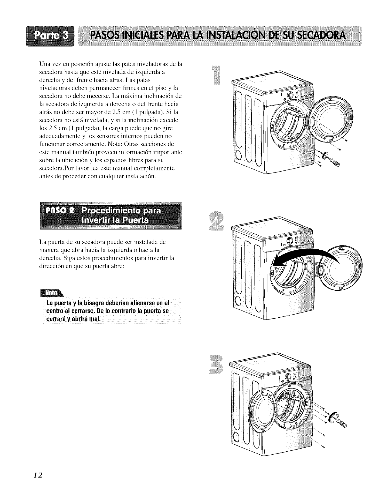
Una vez en posicidn ajuste las patas niveladoras de la
secadora hasta que estd nivelada de izquierda a
derecha y del frente hacia atrfis. Las patas
niveladoras deben permanecer firmes en el piso y la
secadora no debe mecerse. La mfixima inclinaci6n de
la secadora de izquierda a derecha odel frente hacia
atrfis no debe ser mayor de 2.5 cm (1 pulgada). Si la
secadora no estfi nivelada, y si la inclinaci6n excede
los 2.5 cm (1 pulgada), la carga puede que no gire
adecuadamente y los sensores internos pueden no
funcionar correctamente. Nota: Otras secciones de
este manual tambidn proveen informaci6n importante
sobre la ubicaci6n y los espacios libres para su
secadora.Por favor lea este manual completamente
antes de proceder con cualquier instalaci6n.
La puerta de su secadora puede ser instalada de
manera que abra hacia la izquierda o hacia la
derecha. Siga estos procedimientos para invertir la
direcci6n en que su puerta abre:
La puertay la bisagradeberianalienarseen e!
centroal cerrarse.DeIo contrariola puertase
cerrar_ y abrir_ mal,
12
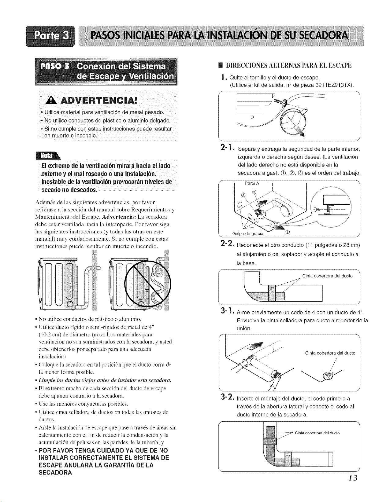
A ADVERTENCiA!
- Utilice material para ventilaci6n de metal pesado.
• No utilice conductos de pl__stico o aluminio delgado.
• Si no cumple con estas instrucciones puede resultar
en muerte o incendio.
El extreme deia ventilaci6n mirar_ hacia eHlade
externe yel mai rescade e aria instalaci6n,:
inestaNe de la ventilaci6n prevecar_n nive!es de
secado no deseades.
Adem_s de las siguientes advertencias, per favor
refidrase a la secci6n del manual sobre Requerimientos y
Mantenimientodd Escape. Advertenda: Lit secadora
debe estar ventiiada hacia llt intemperie. Per favor siga
las siguientes instrucciones (y todas las otras en este
manual) muy cuidadosamente. Si no cumple con estas
instrucciones puede resultar en muerte o incendio.
• No utilice conductos de plfistico o aluminio.
• Utilice ducto rfgido o semi-rigidos de metal de 4"
(10.2 cm) de difimetro (nota: Los materiales para
ventilacidn no son suministrados con la secadora, y usted
debe obtenerlos pot separado para una adecuada
instalacidn)
• Coloque la secadora en tal posici6n que el ducto corra de
la menor forma posible.
• Limpie los duetos viejos ames de instalar esta secadora.
• El extremo macho de cada seccidn del ducto de escape
debe apuntar contrario a la secadora.
• Use las menores conyucturas posibles.
• Utilice cinta selladora de ductos en todas las uniones de
ductos.
• Aisle la instalaci6n de escape que pase a travds de fireassin
calentamiento con el fin de reducir la condensaci6n y la
acumulaci6n de pelusas en las paredes de la tuberia; y
• PeR FAVOR TENGA CUIDADO YA QUE DE NO
INSTALAR CORRECTAIVlENTE EL SISTEMA DE
ESCAPE ANULAR.& LA GARANTiA DE LA
SECADORA
m DIRECCIONESALTERNASPARAEL ESCAPE
1. Quite el tornillo y el ducto de escape.
(Utilice el kit de salida, n° de pieza 3911 EZ9131X).
[
\
2-1.
J
Separe y extraiga la seguridad de la parte inferior,
izquierda o derecha seg0n desee. (La ventilacidn
del lade derecho no estb_disponible en la
secadora a gas). @, @, ® es el orden del trabajo.
Parte A
\ Golpe de gracia @ j
2-2. Reconecte el otro conducto (11 pulgadas o 28 era)
al alojamiento del soplador y acople el conducto a
la base.
Cinta cobertora del ducto
\
3-1. Arme previamente un code de 4 con un ducto de 4".
Envuelva la cinta selladora para ducto alrededor de la
uni6n.
o'/. Inserte el montaje del ducto, el code primero a
traves de la abertura lateral y conecte el codo al
ducto interno de hasecadora.
Cinta cobertora del ducto
13
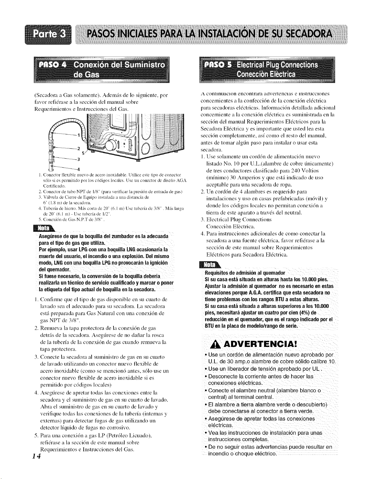
(Secadora a Gas solamente). Ademgs de 1o siguiente, pot
favor refidrase a la seccidn del manual sobre
Requerimientos e Instrucciones del Gas.
4
1. Conector flexible nuevo de acero inoxidable. Utilice esle lipo de coneclor
sdlo si es permitido pot los c6digos locales. Use un conector de disefio AGA
Certificado.
2. Conector de mbo NI_ de 1/8" (para verilicar la presi6n de enlrada de gas)
3. V;ilvula de Cierre de Equipo instalada a una distancia de
6' (1.8 m) de la secadora.
4. Tuberfa de hierro. Mils corta de 2(1' (6. l in) Use tuberfa de 3/8" . Mils larga
de 2(1' (6.1 in) - Use tuberia de 1/2".
5. Conexi6n de Gas N.P.T de 3/8".
Asegfiresede que la boquilladelzumbadoresla adecuada
paraeltipode gasqueutiliza.
Por ejemplo,usarLPGconunaboquillaLNGocasionariala
muertedelusuario,el incendioo unaexplosi6n.Delmismo
modo,LNGconuna boquillaLPGnoprovocarfinla ignici6n
delquemadof
Si fuese necesario,la conversi6ndela b0quilladeberia
realizarlaunt6cnicodeserviciocualificadoy marcaro porter
la etiquetadeltipoactualdeboquilla enla secadora.
I. Confinne que el tipo de gas disponible en su cuarto de
lavado sea el adecuado para su secadora. La secadora
estfi preparada para Gas Natural con una conexi6n de
3 "
gas NPT de :/8 .
2. Remueva la tapa protectora de la conexi6n de gas
detr_s de la secadora. Asegfirese de no dafiar la rosca
de la tuberfa de la conexi6n de gas cuando remueva la
tapa protectora.
3. Conecte la secadora al suministro de gas en su cuarto
de lavado utilizando un conector nuevo flexible de
acero inoxidable (como se mencion6 antes, s61o use un
conector nuevo flexible de acero inoxidable si es
permitido por cddigos locales)
4. Asegfirese de apretar todas las conexiones entre la
secadora y el suministro de gas en su cuarto de lavado.
Abra el suministro de gas en su cuarto de lavado y
verifique todas las conexiones de la tuberla (internas y
externas) para detectar fugas de gas utilizando un
detector liquido de fugas no corrosivo.
5. Para una conexidn a gas LP (Petr61eo Licuado),
refidrase a la seccidn de este manual sobre
Requerimientos e Instrucciones del Gas.
14
A contmuacmn encontmm aOvertencms e mstrucclones
concernientes a la confecci6n de la conexi6n eldctrica
para secadoras eldctricas. Inforrnaci6n detallada adicional
concerniente a la conexi6n eldctrica es suministmda en la
secci6n del manual Requerimientos Eldctricos para la
Secadora Eldctrica yes importante que usted lea esta
seccidn completamente, asf como el resto del manual.
antes de tomar algt]n paso pare instalar o usar esta
secadora.
1. Use solamente un cord6n de alimentaci6n nuevo
listado No. 10 por U.L.(alalnbre de cobre finicamente)
de tres conductores clasiticado pare 240 Voltios
(mfnimo) 30 Amperios y que est_ indicado de uso
aceptable pare una secadom de ropa.
2. Un cord6n de 4 almnbres es requerido para
instalaciones y uso en casas prefabricadas (m6vil) y
donde los c6digos locales no permitan conexi6n a
tierm de este apamto a travds del neutral.
3. Electrical Plug Connections
Conecci6n Elbctrica.
4. Para instrucciones adicionales de como conectar la
secadom a una fuente eldctrica, favor refidrase a la
secci6n de este manual sobre Requemnientos
Eldctricos para Secadora Eldctrica.
Requisitosde admisional quemador
Sisucasaestasituadaenalturashastalos10.000pies.
Ajustarla admisional quemador noesnecesaricen estas
elevacionesporqueA.G.A.certificaqueesta secadorano
tieneproblemasconlosrangosBTUa estasalturas.
Sisucasaestasituadaa alturassuperioresa los 10.000
pies,necesitaraajustarun cuatroporcien(4%) de
reduccionen el quemador,queesel rangoindicadoporel
BTUen la placade modelo/rangodeserie.
ADVERTENCIA!
• Use un corodn de alimentacidn nuevo aprobado pot
U.L de 30 amp.o alambre de cobre sdlido calibre 10.
• Use un liberador de tensi6n aprobado per UL
• Desconecte la corriente antes de hacer las
conexiones el6ctricas.
• Conecte el alambre neutral (alambre blanco o
central) al terminal central.
• El alambre a tierra alambre verde o descubierto)
debe conectarse al conector a tierra verde.
• Aseg0rese de apretar todas las conexiones
el_ctricas,
• Vea las instrucciones de instalaci6n para unas
instrucciones completas.
• De no seguir estas advertencias puede resultar en
incendio o choque el6ctrico.
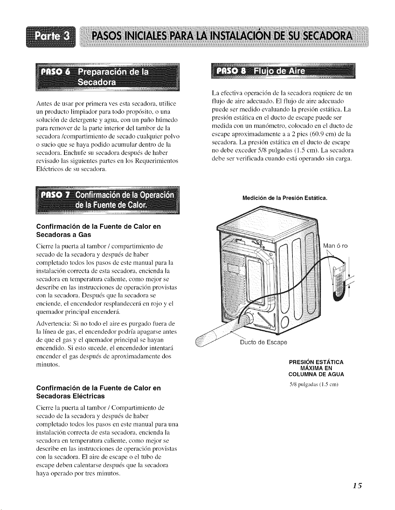
Antes de usar por primera ves esta secadora, utilice
un producto limpiador para todo prop6sito, o una
soluci6n de detergente y agua, con un pa_o hdmedo
para remover de la parte interior del tambor de la
secadora/compartimiento de secado cualquier polvo
o sucio que se haya podido acumular dentro de la
secadora. Enchufe su secadora despuds de haber
revisado las siguientes partes en los Requerimientos
Eldctricos de su secadora.
Confirmacion de la Fuente de Calor en
Secadoras a Gas
Cierre la puerta al tambor / compartimiento de
secado de la secadora y despu6s de haber
completado todos los pasos de este manual para la
instalaci6n correcta de esta secadora, encienda la
secadora en temperatura caliente, como mejor se
describe en las instrucciones de operaci6n provistas
con la secadora. Despuds que la secadora se
enciende, el encendedor resplandecer,-i en rojo y el
quemador principal encender,-i.
Advertencia: Si no todo el aire es purgado fuera de
la lfnea de gas, el encendedor podrfa apagarse antes
de que el gas y el quemador principal se hayan
encendido. Si esto sucede, el encendedor intentar,-i
encender el gas despuds de aproximadamente dos
minutos.
Confirmacion de la Fuente de Calor en
Secadoras Electricas
Cierre la puerta al tambor / Compartimiento de
secado de la secadora y despu6s de haber
completado todos los pasos en este manual para una
instalaci6n correcta de esta secadora, encienda la
secadora en temperatura caliente, como mejor se
describe en las instrucciones de operaci6n provistas
con la secadora. El aire de escape o el tubo de
escape deben calentarse despu6s que la secadora
haya operado por tres minutos.
La efectiva operaci6n de la secadora requiere de un
flujo de aire adecuado. El flujo de aire adecuado
puede ser medido evaluando la presi6n est,fitica. La
presi6n est,fitica en el ducto de escape puede ser
medida con un man6metro, colocado en el ducto de
escape aproximadamente a a 2 pies (60.9 cm) de la
secadora. La presi6n estfitica en el ducto de escape
no debe exceder 518 pulgadas (1.5 cm). La secadora
debe ser verificada cuando est_ operando sin carga.
Medicion de la Presion Estatica.
Man 6 ro
Ducto de Escape
PRESION ESTATICA
MAXIMA EN
COLUMNA DE AGUA
5/8 pulgadas (1.5 cm)
IS
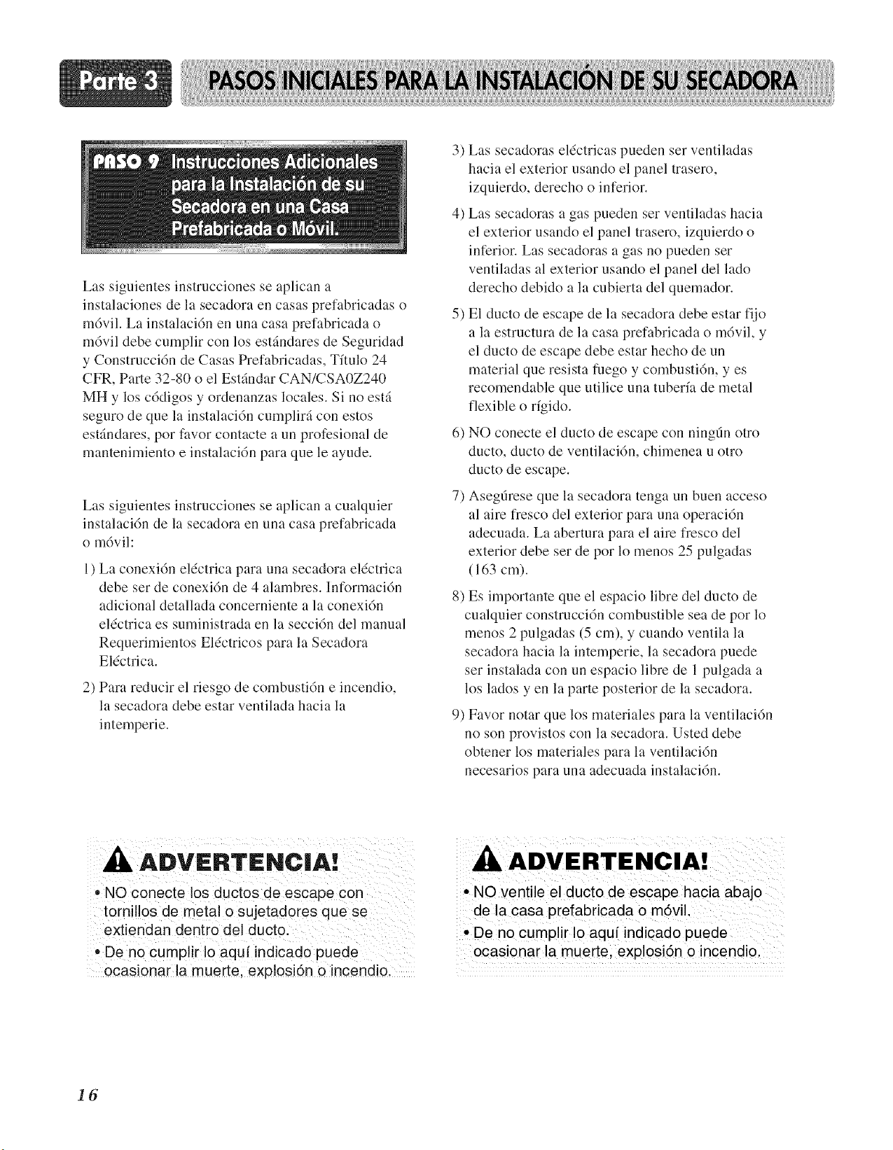
Las siguientes instrucciones se aplican a
instalaciones de la secadora en casas prefabricadas o
m6vil. La instalaci6n en una casa prefabricada o
m6vil debe cumplir con los estfindares de Seguridad
y Construcci6n de Casas Prefabricadas, Tflulo 24
CFR, Parte 32-80 o el Estfindar CAN/CSAOZ240
MH y los c6digos y ordenanzas locales. Si no estfi
seguro de que la instalaci6n cumplirfi con estos
estfindares, pot favor contacte a un profesional de
mantenimiento e instalaci6n para que le ayude.
Las siguientes instrucciones se aplican a cualquier
instalaci6n de la secadora en una casa prefabricada
o m6vil:
l ) La conexi6n eldctrica para una secadora eldctrica
debe ser de conexi6n de 4 alambres. Informaci6n
adicional detallada concerniente a la conexi6n
eldctrica es suministrada en la secci6n del manual
Requerimientos Eldctricos para la Secadora
Eldctfica.
2) Para reducir el riesgo de combusti6n e incendio,
la secadora debe estar ventilada hacia la
intemperie.
3) Las secadoras eldctricas pueden ser ventiladas
hacia el exterior usando el panel trasero,
izquierdo, derecho o interior.
4) Las secadoras a gas pueden ser ventiladas hacia
el exterior usando el panel trasero, izquierdo o
interior. Las secadoras a gas no pueden set
ventiladas al exterior usando el panel del lado
derecho debido a la cubierta del quemador.
5) El ducto de escape de la secadora debe estar fijo
a la estructura de la casa prefabricada o m6viL y
el ducto de escape debe estar hecho de un
material que resista fuego y combusti6m yes
recomendable que utilice una tuberfa de metal
flexible o rfgido.
6) NO conecte el ducto de escape con ningtin otro
ducto, ducto de ventilacidm chimenea u otro
ducto de escape.
7) Asegtirese que la secadora tenga un buen acceso
al aire fresco del exterior para una operaci6n
adecuada. La abertura para el aire fresco del
exterior debe ser de por 1o menos 25 pulgadas
( 163 cm).
8) Es importante que el espacio libre del ducto de
cualquier construcci6n combustible sea de pot 1o
menos 2 pulgadas (5 cm), y cuando ventila la
secadora hacia la intemperi< la secadora puede
set instalada con un espacio libre de 1 pulgada a
los lados yen la parte posterior de la secadora.
9) Favor notar que los materiales para la ventilaci6n
no son provistos con la secadora. Usted debe
obtener los materiales para la ventilaci6n
necesarios para una adecuada instalaci6n.
ADVERTENC|A!
* NO conecte los ductos de escape con
torni los de metal o sujetadores que se
extiendan dentro del ducto,
* De no cumplir Io aqui indicado puede
ocasionar la muerte, explosi6n o incendio.
i ii_ i i_ii i_ _ii _ iI _ii i i
• NO venti e el ducto de escape hacia abajo
de la casa prefabricad a o mOvil.
• Deno cump!ir Io aqui indicado puede
ocasionar la muerte, explosi6n o incendio,
16
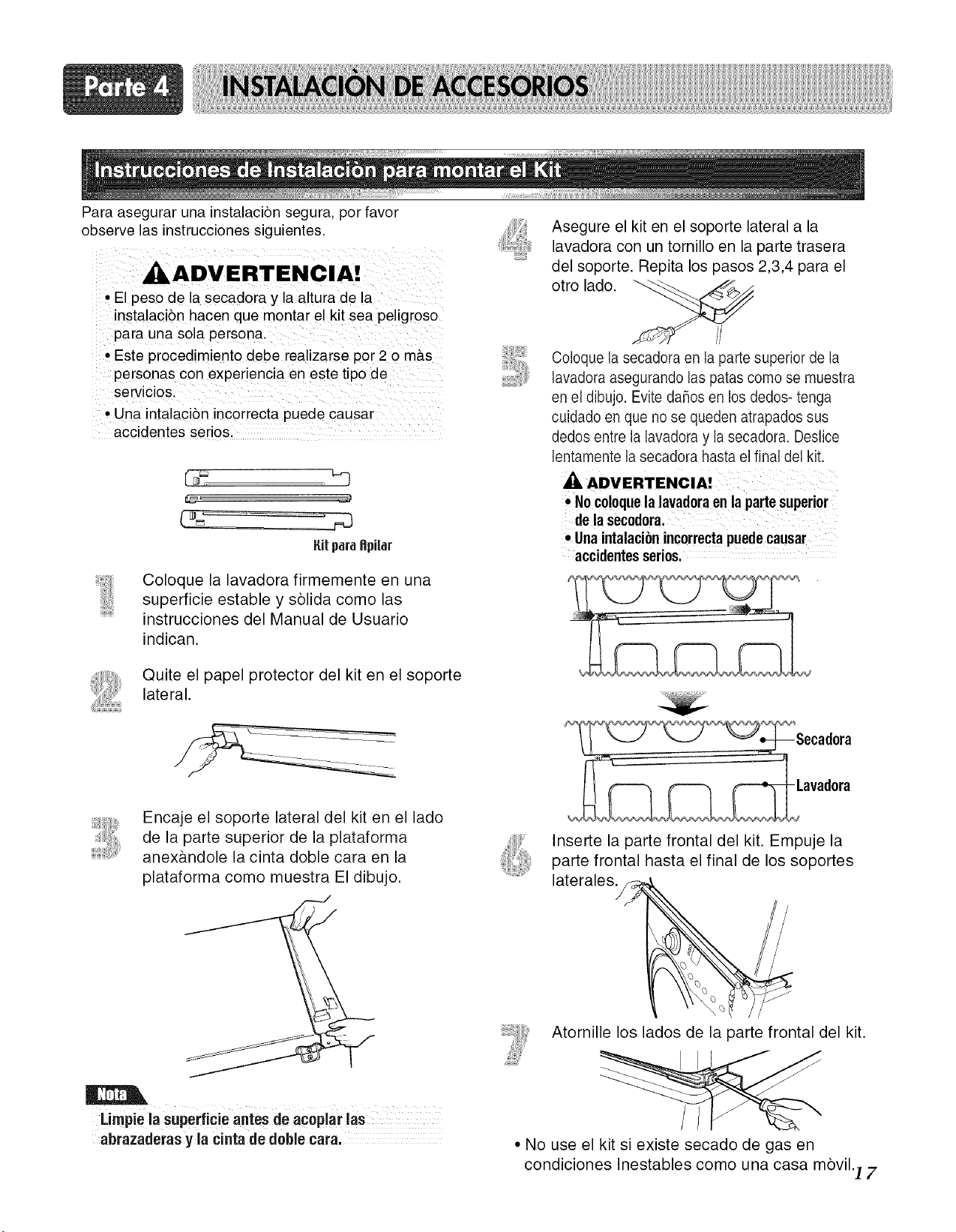
Para asegurar una instalaciSn segura, por favor
observe las instrucciones siguientes.
ADVERTENCIA!
• El peso de la secadora y la altura de la
instalacibn hacen que montar el kit sea peligroso
para una sola persona.
• Este procedimiento debe realizarse por 2 o m&s
personas con experiencia en este tipo de
servicios.
° Una intalacibn incorrecta puede causar
accidentes serios.
Ritparaflpiiar
Coloque la lavadora firmemente en una
superficie estable y sblida como las
instrucciones del Manual de Usuario
indican.
Quite el papel protector del kit en el soporte
lateral.
Asegure el kit en el soporte lateral a la
lavadora con un tornillo en la parte trasera
del soporte. Repita los pasos 2,3,4 para el
otro lado.
Coloque la secadora en la parte superior de la
lavadora asegurando las patas como se muestra
en el dibujo. Evite dares en los dedos- tenga
cuidado en que no se queden atrapados sus
dedos entre la lavadora y la secadora. Deslice
lentamente la secadora hasta el final del kit.
• No co!oquela lavadoraen la parte superior
de la secodora.
• Unaintalacionincorrectapuedecausar
accidentesserios,
Encaje el soporte lateral del kit en el lado
de la parte superior de la plataforma
anex&ndole la cinta doble cara en la
plataforma como muestra El dibujo.
Limpie la superficie antes de acoplar !as
abrazaderas y la cinta de dobie tara.
Inserte la parte frontal del kit. Empuje la
parte frontal hasta el final de los soportes
laterales_f_
Atornille los lados de la parte frontal eel kit.
• No use el kit si existe secado de gas en
condiciones Inestables como una casa mbvil.] 7

Quite el pedestal, instalaci6n del disco duro e
instrucciones del cart6n del envio.
Coloque la secadora encima del pedestal.
NOTA : Debido al peso de la secadora, pueden
necesitarse dos o m&spersonas.
NOTA : Si la secadora fuera instalada
previamente, desinstalela como sigue:
A. Desinstalando la secadora eletrica:
1) Desenchufe el cord6n de suministro de
energia.
2) Jale la secadora fuera de la pared Io
suficiente para aflojar la abrazadera del
conducto de ventilaci6n. Suelte la abrazadera
y quite cuidadosamente el extractor del
conducto de ventilacion del enchufe del
extractor de la secadora.
B. Desinstalacion de una secadora a gas:
1) Cierre el gas.
2) Desenchufe el cable de alimentaci6n.
3) Desconecte la Ifnea de gas de la secadora.
4) Deje a un lado y afloje la brida de ventilaci6n.
5) Desconecte la ventilaci6n.
Atar la cinta de doble-cara del anaquel al secador
como se muestra para que la inclinaci6n de las
partes de los anaqueles se alinien con el horde y
puedan atarse al pedestal con los tornillos.
NOTA : Ate la parte mas baja primero.
Asegerese de ajustar las partes adhesivas de los
anaqueles firmemente al aparato.
la
lavadora/combo
secadora
Instale los ocho(8) tornillos (proporcionados) para
atar los anaqueles al pedestal.
-- para la secadora
Parala
lavadora/combo
18
Quitar el papel del anaquel.
Mover la secadora al lugar deseado.
NOTA : El aparato y el pedestal ensamblado deben
ponerse sobre suelo s61idoy nivelado para
un funcionamiento apropiado. Ajuste las
patas del aparato y el pedestal dando
vueltas con la Ilave inglesa.Entonces,
ajuste el seguro de la cerradura hacia el
pedestal mientras sosteniene la pata del
pedestal usando la Ilave inglesa.
Las siguientes son instrucciones adicionales sobre las conexiones y requerimientos eldctricos para las secadoras
eldctricas.
,_ Adverteneia: El cableado y la conexi6n a tierra deben estar de acuerdo con la edicidn mils reciente del
cddigo Eldctrico Nacional, ANSI/NFPA 70 y todas las regulaciones locales aplicables. Por favor contacte a un
electricista calificado para verificar el cableado y fusibles de su casa y para asegurar que tiene la energia eldctrica
adecuada para el funcionamiento de la secadora. De no seguir estas advertencias puede resultar en incendio o
choque eldctrico.
120V/240",1, 60 Hertz, Instalacidn de 3-Alambres
Instrucciones para la Conexion a Tierra de
su Secadora Electrica:
a) Por favor note que el diagrama de cableado estfi
localizado dentro de la cubierta del control de la
secadora.
b) Esta secadora debe ser conectada a un metal
con conexidn a tierra, sistema de cableado
permanente, o un conductor equipo-tierra debe
correr con los conductores de circuito y estar
conectado al terminal equipo-tierra o lfnea
principal de la secadora.
c) La secadora tiene su propia caja terminal la cual
debe estar conectada a una lfnea separada,
60 Hertz, circuito de fase sencilla, circuito AC
(corriente alterna), con fusible de 30 Amperios
(el circuito debe tener fusibles en ambos lados
de la lfnea). EL SERVICIO ELt_CTRICO
PARA LA SECADORA DEBE SER DEL
MAXIMO RANGO DE VOLTAJE DESCRITO
EN LA PLACA. NO CONECTE LA
SECADORA A UN CIRCUITO DE 110, 115,
6 120 VOLTIOS. Hay elementos calefactores
disponibles para secadoras que se conectarfin a
servicios eldctricos de diferente voltaje que los
que se listan en la placa, tal como de 208
voltios.
e) La conexi6n del cord6n de alimentaci6n (cable
flexible) entre el tomacorriente y la caja terminal
de la secadora NO ES suministrada con la
secadora. El tipo del cable flexible y el calibre del
alambre deben estar conforme con los c6digos
locales y con las instrucciones de las pfiginas
siguientes.
f) El mdtodo de cableado de la secadora es opcional
y sujeto a los requerimientos del cddigo local.
Refidrase a los ejemplos en la prdxima pfigina.
g) Usted debe seleccionar el mdtodo para cablear su
secadora de acuerdo a los requerimientos de los
c6digos locales y ordenanzas. Mdtodos de
ejemplo estfin incluidos en las siguientes pfiginas.
DVERTENCIA!
• Etiquete todos los cables antes de
desconectarlos para darle mantenimiento a
la secadora, ya que errores en el cableade
pueden causar lesiones serias a usted y
dahar su secadora.
• De no seguir estas advertencias puede
resultar en incendio o cheque elOctrico.!
d) Si la distancia entre la caja de circuito y la
secadora es de 15 pies (4.50 m) o menos, use un
cable No. 10 A.W.G. (de cobre dnicamente)
listado por U.L. (Underwriters Laboratories), o
como 1o requieran los c6digos locales. Si es de
mils de 15 pies (4.50 m), use un cable No. 8
A.W.G. (de cobre dnicamente) listado por U.L
(Underwriters Laboratories) o como 1o
requieran los c6digos locales. Deje suficiente
holgura en el cableado de manera que la
secadora pueda ser movida de su posici6n
cuando sea necesario.
19

Revise las siguientes opciones para determinar la conexibn el6ctrica adecuada
para su casa:
@
Utilice las instrucciones en esta secci6n si su casa
tiene un tomacorriente de 4-alambres (Tipo NEMA
14-30R) y si usar,fi un cord6n de alimentaci6n para
secadora listado por UL, de 1201240 voltios minimo
y de 30 amp.
Utilice las instrucciones en esta secci6n si su casa
tiene un tomacorriente de 3-alambres (Tipo NEMA
10-30R) y si usar,fi un cord6n de alimentaci6n para
secadora listado por UL, de 1201240 voltios minimo
y de 30 amp.
Si este tipo est_ disponible en su casa, 1oconectar_ a
una caja de corto circuito o una pipa desconectada.
Si este tipo est_ disponible en su casa, 1oconectar_ a
una caja de corto circuito o una pipa desconectada.
• Atornilleel cablede la alimentaci6nal bloque
terminal.Elcablede colordeberiaconectarsea los
tornillosdel mismocolor.Elcolordel cable indicada
enel manualest_ conectadoal tornillodelmismo
colordel bloque.De Io contrario,se aplicar_una
corrienteexcesivaqueocasionar_da_osal producto
yunfallo en la calefacci6n.
2O
Advertenda: Contacto por conductor neutro esta prohibido
por(1) nuevas instalciones de branch- circuito (2) las casas de
mobiles (3) vehiculo recreacional y (4) areas donde los codigos
locales prohibe contactar por el conductor neutro. De no seguir
estas advertencias puede resultar en incendio o choque
eldctrico.
Prepare un minimo de 5 ps (1.52 m) de longitud para poder
reemplazar la secadora.
Primero, despegue 5 pulg (12.7 cm) de la cubierta del cable
desde el final. Descubra 5 pulgadas del cable de tierra. DespuEs
de cortar 1112 pul (3.8cm) de los otros 3 cables, aisle Io
despegado, atr'as lpul (2.5Cln).haga los finales de los cables ell
torlna de gancho. ¢
Luego, ponga el final de esas puntas debajo del tornillo de la
terminal (la parte de la punta con torma de gancho mostrandose
derecho) y una el cable con el tornillo fuertemente.
&
1.Conecteun cableneutral (blanco)al corddn de poder paracentrar
la terminaldel tornillo.
2. Conecteun cablerojo y otro Negroen lasterminalesizquierdasy
derechasde los tornillos.
3. Conecteel cable de tierra (verde) del corddn de poderal tornillode
tierraexterno y muevael cable de tierra neutralfuera del aparatoy
condcteloal tornillocentral.
4. Asegfiresequeel tornillode aliviode tensidneste apretado.
Asegureque todo el bloquede tuercasesten bien apretados,y el
cableeldctricode podereste en la posicidncorrecta.
Tornillo de bloque terminal
central (Plata)
Cable de Tierra neutral
(blanco)
Cable Neutral
(blanco o Cable central)
Tensor de Alivio
CableVerdedel cord6nde Poder
Conector Externo de Tierra
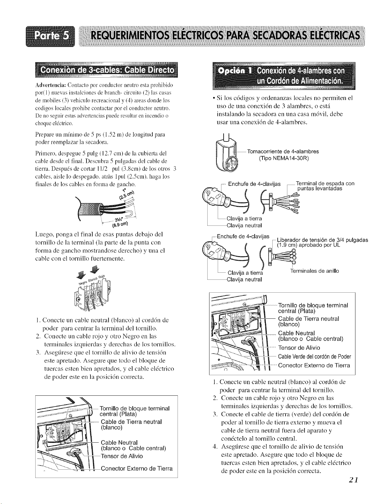
Advertenda: Contacto por conductor neutro esta prohibido
por(1) nuevas instalciones de branch- circuito (2) las casas
de mobiles (3) vehiculo recreacional y (4) tueas don& los
codigos locales prohibe contactar por el conductor neutm.
De no se_uir estas advertencias puede resultar ell incendio o
choque eldctrico.
Prepare un minimo de 5 ps (1.52 In) de longitud para
poder reemplazar la secadora.
Pdmero, despegue 5 pulg (12.7 cm) de la cubierta del
cable desde el final. Descubra 5 pulgadas del cable de
tierm. Despu4s de cortar 1112 pul (3.8cm) de los otros 3
cables, aisle 1o despegado, atr2ts lpul (2.5cm). haga los
finales de los cables en forma de gancho.
,¢
Luego, ponga el final de esas puntas debajo del
tornillo de la terminal (la parte de la punta con
forma de gancho mostrandose derecho) y una el
cable con el tornillo fuertemente.
• Si los c6digos y ordenanzas locales no permiten el
uso de una conexi6n de 3 alambres, o estfi
instalando la secadora en una casa m6vil, debe
usar una conexi6n de 4-alambres.
Tomacorriente de 4-alambres
(Tipo NEMA14-30R)
Enchufe de 4-clavijas _Termina! de espada con
puntas levantaaas
Clavija a tierra
_Clavija neutral
........Enchufe de 4-clavijas
..-_"-' r Liberador de tensi6n de 3/4 pulgadas
[ _ ClaavV.12a2_t::_ Terminales de anillo
1. Conecte un cable neutral (blanco) al cord6n de
poder para centrar la terminal del tornillo.
2. Conecte un cable rojo y otto Negro en las
terminales izquierdas y derechas de los tornillos.
3. Asegdrese que el tornillo de alivio de tensi6n
este apretado. Asegure que todo el bloque de
tuercas esten bien apretados, y el cable eldctrico
de poder este en la posici6n correcta.
Tornillo de Noque terminal
central (Plata)
Cable de Tierra neutral
(blanco)
Cable Neutral
(blanco o Cable central)
de Alivio
Conector Externo de Tierra
Tornillo de bloque terminal
__,_/! centrN (Plata)
__i _T Cable de Tierra neutral
__-_,..J _ / (blanco)
Cable Neutral
_'_-_'_\ t l (Nancoo Cable central)
...................Tensor de Alivio
-_...__ CableVerdedel cord6ndePoder
1. Conecte un cable neutral (blanco) al cord6n de
poder para centrar la terminal del tornino.
2. Conecte un cable rojo y otro Negro en las
terminales izquierdas y derechas de los tornillos.
3. Conecte el cable de tierra (verde) del cord6n de
poder al tornillo de tierra externo y mueva el
cable de tierra neutral fuera del aparato y
condctelo al tornillo central.
4. Asegdrese que el tornino de alivio de tensi6n
este apretado. Asegure que todo el bloque de
tuercas esten bien apretados, y el cable eldctrico
de poder este en la posici6n correcta.
21
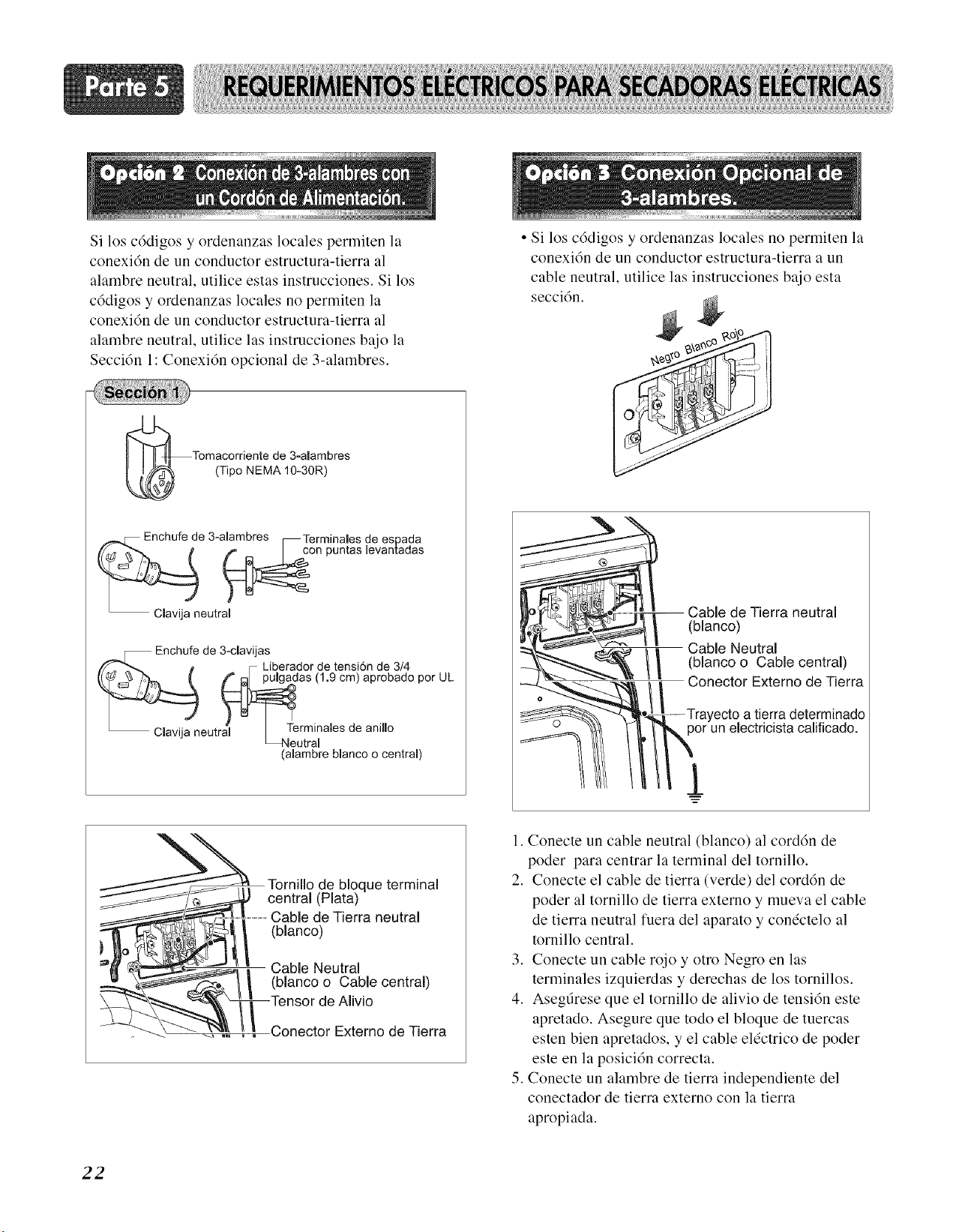
Si los cddigos y ordenanzas locales permiten la
conexi6n de un conductor estructura-tierra al
alambre neutral, utilice estas instrucciones. Si los
c6digos y ordenanzas locales no permiten la
conexi6n de un conductor estructura-tierra al
alambre neutral, utilice las instrucciones bajo la
Secci6n 1: Conexi6n opcional de 3-alambres.
• Si los c6digos y ordenanzas locales no permiten la
conexi6n de un conductor estructura-tierra a un
cable neutral, utilice las instrucciones bajo esta
secci6n.
Tomacorriente de 3-alambres
(Tipo NEMA 10-30R)
Enchufe de 3-alambres _Terminales de espada
on puntas levantadas
eutral
Enchufe de 3-clavijas
• Liberador de tensi6n de 3/4
as (1.9 cm) aprobado por UL
eutra'l _,Terminales de anino
(alambre blanco o central)
-- Cable de Tierra neutral
(blanco)
Cable Neutral
//_ (blanco o Cable central)
Conector Externo de Tierra
a tierra determinado
electricista calificado.
1
l'ornillo de bloque terminal
central (Plata)
Cable de Tierra neutral
(blanco)
Cable Neutral
(blanco o Cable central)
de Alivio
Externo de Tierra
1. Conecte un cable neutral (blanco) al cord6n de
poder para centrar la terminal del tornillo.
2. Conecte el cable de tierra (verde) del cord6n de
poder al tornillo de tierra externo y mueva el cable
de tierra neutral fuera del aparato y condctelo al
tornillo central.
3. Conecte un cable rojo y otro Negro en las
terminales izquierdas y derechas de los toruillos.
4. Asegdrese que el tornillo de alivio de tensi6u este
apretado. Asegure que todo el bloque de tuercas
esteu bien apretados, y el cable el(ctrico de poder
este en la posici6u correcta.
5. Couecte uu alambre de tierra iudepeudieute del
couectador de tierra externo con la tierra
apropiada.
22
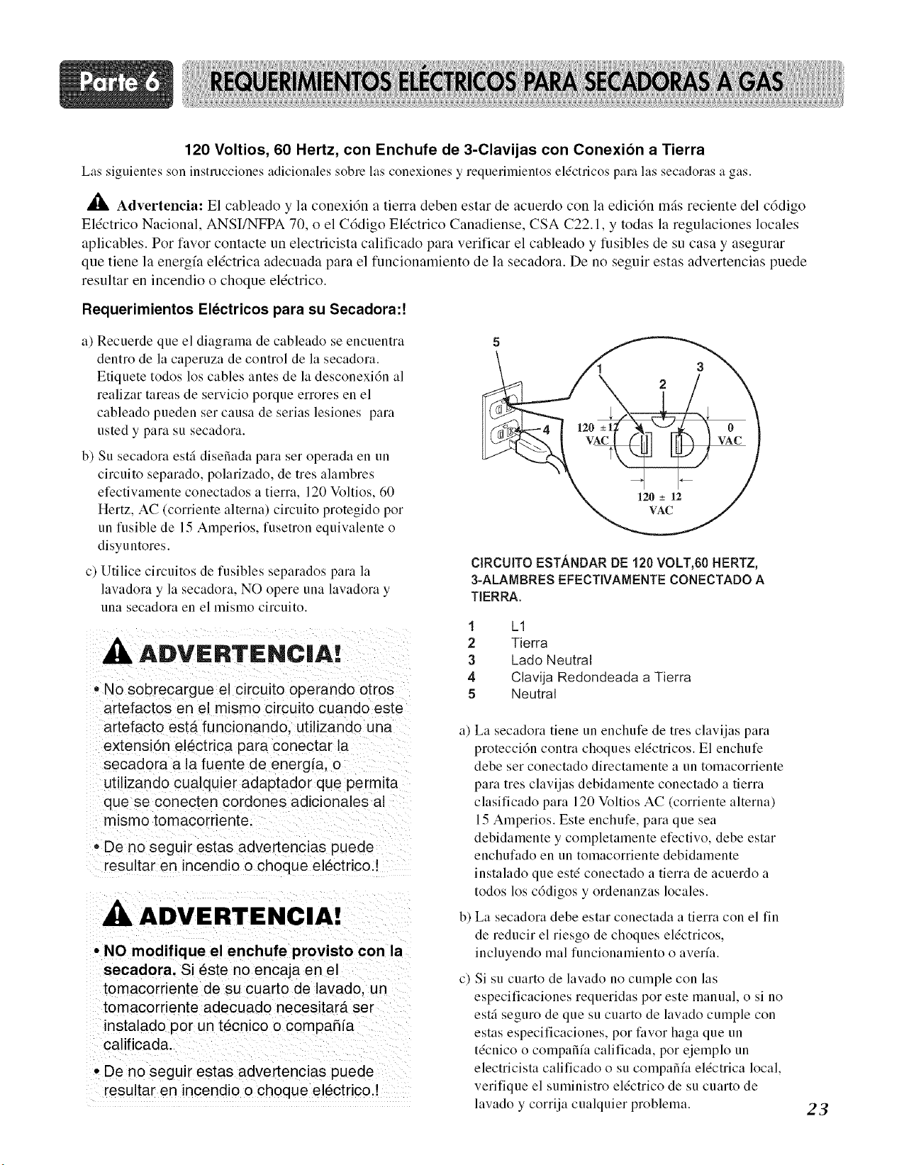
120 Voltios, 60 Hertz, con Enchufe de 3-Clavijas con Conexion a Tierra
Las siguientes son instrucciones adicionales sobre las conexiones y requerimientos eldctricos para las secadoras a gas.
,_t Advertencia: El cableado y la conexidn a tierra deben estar de acuerdo con la edici6n mils reciente del cddigo
Eldctrico Nacional, ANSI/NFPA 70, o el C6digo Eldctrico Canadiense, CSA C22.1, y todas la regulaciones locales
aplicables. Por favor contacte un electricista calificado para verificar el cableado y fusibles de su casa y asegurar
que tiene la energfa eldctrica adecuada para el funcionamiento de la secadora. De no seguir estas advertencias puede
resultar en incendio o choque eldctrico.
Requerimientos Electricos para su Secadora:!
a) Recuerde que el diagrama de cableado se encuentra
dentro de la caperuza de control de la secadora.
Etiquete todos los cables antes de la desconexidn al
realizar tareas de servicio porque errores en el
cableado pueden set causa de serias lesiones para
usted y para su secadora.
b) Su secadora estfi disefiada para ser operada en un
circuim separado, polarizado, de tres alambres
efectivamente conectados a tierra, 120 Voltios, 60
Hertz, AC (corriente alterna) circuim protegido por
un fusible de 15 Amperios, fusetron equivalente o
disyuntores.
c) Utilice circuitos de fusibles separados para la
lavadora y la secadora, NO opere una lavadora y
una secadora en el mismo circuito.
ADVIERTENC|A!
• No sobrecargue el circuito operando otros
artefactos en el m_smo circuito cuando este
artefacto estfi funcionando, utilizando una
extensidn el_ctrica para conectar la
secadora a la fuente de energia, o
utilizando cualquier adaptador que permita
que se conecten cordones adicionales al
mismo tomacordente.
• De no seguir estas advertencias puede
resultar en incendio o cheque el6ctrico !
ADVERTENCIA!
• NO modifique el enchufe provisto con la
secadora. Si _ste no encaja en el
tomacorriente de su cuarto de lavado, un
tomacorriente adecuado necesitarfi ser
instalado por un t6cnico o compafiia
calificada.
• De no seguir estas advertencias puede
resultar en incendio o cheque el6ctrico.!
ClRCUITO ESTANDAR DE 120 VOLT,60 HERTZ,
3-ALAMBRES EFECTIVAMENTE CONECTADO A
TIERRA.
1
2
3
4
5
LI
Tierra
Lado Neutral
Clavija Redondeada a Tierra
Neutral
a) La secadora tiene un enchufe de tres clavijas para
protecci6n contra choques el&tricos. El enchufe
debe ser conectado directamente a un tomacorriente
para tres clavijas debidamente conectado a tierra
clasificado para 120 Voltios AC (corriente alterna)
15 Amperios. Este enchufe, para que sea
debidamente y completamente efectivo, debe estar
enchufado en un tomacorriente debidamente
instalado que est_ conectado a tierra de acuerdo a
todos los c6digos y ordenanzas locales.
b) La secadora debe estar conectada a tierra con el fin
de reducir el riesgo de choques el&tricos,
incluyendo mal funcionamienm o averfa.
c) Si su cuarm de lavado no cumple con las
especificaciones requeridas pot este manual, o si no
estfi seguro de que su cuarto de lavado cumple con
estas especificaciones, por favor haga que un
tdcnico o compafifa calificada, por ejemplo un
electricista calificado o su compafifa el&trica local,
verifique el suministro el&trico de su cuarto de
lavado y corrija cualquier problema.
23
Las siguientes son instrucciones e informacidn importante concernientes a los requerimientos para el suministro y
servicio del gas para las secadoras a gas. ,_ Adverteneia: El suministro y servicio del gas para las secadoras a gas
debe cumplir con los c6digos y ordenanzas locales. Si no existen c6digos y ordenanzas locales en su firea, el
suministro y servicio del gas para su secadora a gas debe cumplir con la mils reciente edici6n del C6digo Nacional de
Gas Combustible, ANSI Z223.1 / NFPA 54. De no cumplir 1o aquf indicado puede ocasionar la muerte, explosi6n o
incendio.
1. Requerimientos del suministro de gas: El servicio
de Gas Petr61eo Licuado (L.P.) (2,500 Btu/ft3 (93.1
MJ/m3)) debe set suministrado a una presi6n de
columna de agua de 10 + 1.5 pulgadas.
2. No intente conectar la Secadora al Servicio de Gas
Petr61eo Liquido (LP Gas) sin personal calificado.
3. Aisle la secadora del sistema de tuberfas del
suministro de gas cerrando la vfilvula individual de
cierre manual, durante las pruebas de presi6n del
sistema de suministro de gas a la presi6n de prueba
igual o menor que 211 psi (3.45 kPa).
4. Requerimientos de la Linea de Suministro. Su
cuarto de lavado debe tener una lfnea rfgida de
suministro de gas hasta la secadora. En USA, una
vfilvula individual de cierre manual DEBE ser
instalada a no mils de 6 pies (1.8 m) de la secadora
de acuerdo con Cddigo Nacional de Gas
Combustible ANSI Z223.1. Un conector de tuberfa
N.RT. de 1/8 pulgada debe ser instalado como se
muestra.
ADVERTE.
• NO intente desmontar la secadora, esta
acci6n requiere la atenci6n y
herramientas de un tecnico o compaS!a
autorizada y calificadal
• De no cump!ir !0 aqu! indicado puede
ocasionar la muerte; explosi6n o
incendio.
Instrucciones y ADVERTENCIAS:
• Conecte la secadora al tipo de gas indicado en la
placa de la secadora.
• Utilice conectores nuevos flexibles de acero
inoxidable.
• Utilice cinta de Tefldn y sellador de uniones
insoluble en gas LP en todas las roscas de las
tuberfas.
• Purgue el suministro de gas de aire y sedimentos
antes de conectarlo a la secadora; con el propdsito de
evitar contalninacidn de la vfilvula de gas, antes de
apretar la conexidn entre el suministro de gas y la
secadora, purgue el aire que queda hasta que el olor a
gas sea detectado.
• NO use una flama para detectar fugas de gas; en su
lugar, utilice un lfquido detector de fugas no
corrosivo.
ADVERTENCIA!
• Utilice una Ifnea nueva de suministro de gas
aprobada per AGA o CSA.
• Instale una vfilvula de cierre.
• Asegt_rese de apretar todas las conexiones de
gas.
• Si estfi conectado a LR haga que un tecnico
calificado se asegure que la presi6n de gas no
exceda la columna de agua de 13 pulgadas.
• Ejemplos de los t6cnicos calificados incluyen
personal con licencia sobre calefacci6n
personal autorizado de la compaSfa de gas, y
persona_ autorizado de servicio.
• De no cumplir Io aqui indicado puede
ocasionar la muerte, explosi6n o incendio.
24
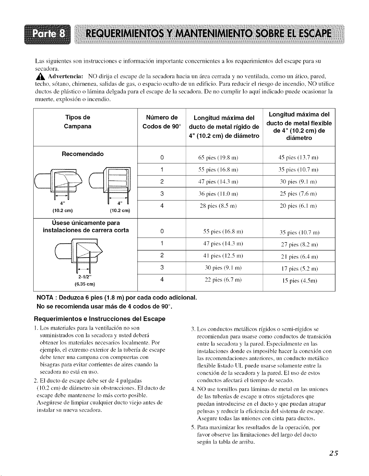
Las siguientes son instrucciones e informacidn importante concernientes a los requerimientos del escape para su
secadora.
Advertenda: NO dirija el escape de la secadora hacia un firea cerrada y no ventilada, como un fitico, pared,
techo, s6tano, chimenea, salidas de gas, o espacio oculto de un edificio. Para reducir el riesgo de incendio, NO utilice
ductos de plfistico o lfimina delgada para el escape de la secadora. De no cumplir 1o aquf indicado puede ocasionar la
muerte, explosi6n o incendio.
Tipos de
Campana
Recomendado
4 _
(10.2 cm)
H
4 _
(10.2 cm)
Usese dnicamente para
instalaciones de carrera corta
Ndmero de
Codos de 90 °
0
1
2
3
4
Longitud mz_xima del
ducto de metal rigido de
4" (10.2 cm) de di_metro
65 pies (19.8 m)
55 pies (16.8 m)
47 pies (14.3 m)
36 pies (11.0 m)
28 pies (8.5 m)
55 pies (16.8 m)
Longitud m_xima del
ducto de metal flexible
de 4" (10.2 cm) de
diz_metro
45 pies (13.7 m)
35 pies (10.7 m)
30 pies (9.1 m)
25 pies (7.6 m)
20 pies (6.1 m)
35 pies (10.7 m)
1
2
3
4
2-1/2"
(6.35 cm)
47 pies (14.3 m)
41 pies (12.5 m)
30 pies (9.1 m)
22 pies (6.7 m)
27 pies (8.2 m)
21 pies (6.4 m)
17 pies (5.2 m)
15 pies (4.5m)
NOTA : Deduzca 6 pies (1.8 m) por cada codo adicional.
No se recomienda usar mz_sde 4 codos de 90 °.
Requerimientos e Instrucciones del Escape
I. Los lnateriales para la ventilaci6n no son
suministrados con la secadora y usted deberfi
obtener los materiales necesarios localmente. Pot
ejemplo, el extremo exterior de la tuberfa de escape
debe tenet una campana con compuertas con
bisagras para evitar corrientes de aires cuando la
secadora 110 esti en uso.
2. El ducto de escape debe set de 4 pulgadas
(10.2 cm) de diimetro sin obstrucciones. El ducto de
escape debe mantenerse 1o mils corto posible.
Asegfirese de limpiar cualquier ducto viejo antes de
instalar su nueva secadora.
3. Los conductos metilicos r;gidos o semi-rfgidos se
recomiendan para usarse como conductos de transicidn
entre la secadora y la pared. Especialmente en las
instalaciones donde es imposible hacer la conexidn con
las recomendaciones anteriores, un conducto metilico
flexible listado UL puede usarse solamente entre la
conexi6n de la secadora y la pared. El uso de estos
conductos afectari el tiempo de secado.
4. NO use tornillos para liminas de metal en las uniones
de las tuber;as de escape u otros sujetadores que
puedan introducirse en el ducto y que puedan atrapar
pelusas y reducir la eficiencia del sistema de escape.
Asegure todas las uniones con cinta para ductos.
5. Para maximizar los resultados de la operacidn, por
favor observe las limitaciones del largo del ducto
segfin la tabla de arriba.
2_
Mantenimiento del Escape y la Secadora
ADVERTENCIA!
• Desconecte la energfa el6ctrica de la secadora
antes de efectuar limpieza o mantenimiento
• De no seguir estas advertencias puede
resultar en incendio o choque el6ctrico
26
1. Despuds de un atio de uso, el interior y todo el sistema
de escape de la secadora debe ser examinado y
limpiado si es necesario.
2. Antes de que transcurra un atio de uso, si el
rendimiento del secado ha bajado repentinalnente a
niveles insatisfactorios, examine y limpie el conducto
de salida para conseguir un mejor nivel de secado.
3. Veriflque la campana fiecuentemente para asegurarse
que las compuertas se est_n moviendo librelnente, que
no hayan sido elnpujadas hacia adentro, y que nada
haya sido recargado contra las compuertas.
4. Un tdcnico de servicio o compati/a calificada debe ser
utilizada para realizar este mantenimiento.
5. Un equipo de Ventilacidn Flexible, disponible a costo
extra, puede utilizarse cuando el escape de la secadora
esta situado en lugares diffciles de alcanzar. Este equipo
viene en dos piezas, una se adjunta a la secadora y la otra
a la salida del escape de la pared. Despuds de haber fijado
las dos piezas por separado a la secadora y a la pared, la
secadora puede retornar a su posicidn final, para luego
conectar las dos piezas entre si.
7. Usuahnente, el talnbor de la secadora no necesita
cuidado. Limpie el exterior de la secadora cuando sea
necesario, y sielnpre inlnediatamente cuando se
demune en la secadora cualquier detergente,
blanqueador, u otro producto para lavar, debido que
estos productos pueden causar datios permanentes al
acabado exterior de la secadora.
8. Limpie el panel de control con un patio hdmedo
cuando sea necesario. Advertencia: los productos de
pre-lavados en spray pueden datiar el acabado del
panel de control.
9. Por favor limpie el filtro de pelusa antes o despuds de
secar cada carga.
10. Siempre asegdrese que el filtro de pelusa estd limpio antes
de empezar una nueva carga, debido a que un filtro de
pelusa obstruido puede aumentar el tiempo de secado.
11. Anuahnente remueva el flltro de pelusa y col6quelo
bajo el ducto de la aspiradora. Vea el item #2 arriba.
12. Por favor note que el diagrama de cableado se
localiza dentro de la cubierta de los controles de la
secadora. Etiquete todos los cables antes de
desconectarlos al darle mantenimiento a la secadora,
debido a que errores en el cableado pueden causar
lesiones serias a usted y datio a su secadora.
Limpieza de la Malla de Pelusa
1. Limpie el filtro de pelusa antes o despu& de haber
secado cada carga. Siempre asegdrese que el filtro
de pelusa est_ limpio antes de empezar una nueva
carga, debido a que un filtro de pelusa obstruido
puede aumentar el tiempo de secado.
2. Para limpiarlo, tire de la malla de pelusa hacia
arriba y enrolle la pelusa fuera de la malla con los
dedos. No enjuague o lave la malla para remover la
pelusa, debido a que la pelusa mojada es diffcil de
quitar. Elnpuje la malla de pelusa firmemente de
vuelta a su lugar.
3. Siempre asegdrese que la malla de pelusa est_
firlnemente colocada antes de operar la secadora.
Operar la secadora sin la malla de pelusa puede
causar sobrecalentamiento y causar dafio a la
secadora como a los artfculos que estfi secando.
4. Algunas prendas pueden vertir m'as pelusa que
otras (mallas por ejemplo), ocasionando que el filtro
atrapapelusa se llene muy rg_pido.
Remueva la pelusa de la malla de pelusa antes y
despu& de haber secados esms artfculos, tales como
toallas nuevas.
5. En el caso que la pelusa se caiga de la malla dentro
de la secadora durante la remoci6n, verifique el
conducm de escape y quite cualquier pelusa.
6. El detergente para lavar y los residuos del
suavizante de tela se pueden acumular en la malla
de pelusa, causando tiempos de secado mils largos.
La malla probablemente se bloqueari si cae pelusa
sobre ella. Con el fin de prevenir este tipo de
acumulaci6n, y ayudar a asegurar un
funcionamiento adecuado de su secadora, limpie la
malla de pelusa con un cepillo de nailon cada seis
meses, o si es necesario, mils frecuentemente. El
filtro de pelusa tambi&l puede lavarse de la
siguiente manera:
a) Despu& de haber enrollado la pelusa fuera de la
malla con los dedos, moje ambos lados de la malla
con agua caliente o tibia.
b) Moje un cepillo de nailon con agua caliente y
detergente l/quido y restriegue la malla de pelusa
para remover la acumulacidn de residuos de
detergente y suavizante de tela.
c) Repita el proceso como sea necesario.
d) Despu& que los residuos hayan sido removidos,
enjuague la malla con agua caliente.
e) Despu& de secar la malla de pelusa con una toalla
limpia, Coloqu( firmelnente la malla de vuelta en la
secadora.
Las siguientes son las instrucciones para encender y utilizar su nueva secadora. Por favor refidrase alas secciones especificas de
este manual para infonnaci6n m4s detallada. Advertencia hnportante: Para reducir el riesgo de incendio, choque eldctrico, o
lesiones personales lea este manual colnpletamente, incluyendo las Instrucciones de Seguridad hnportantes, antes de operar esta
secadora.
Bot6nde
SeleccJ6n Programa Bot6nde carnbio
del ciclo Personalizado de tJempo
La Pantallade LED
COTTON/TOWELS ,
CU_'TOM
PROGRAM
O NORMAL O MEDIUM O 40 @ LOW C) WRINKLECARE
© LESSDRY © LOW © 30
O DAMPDRY O ULTRALOWO 20 O OFF O DAMPDRYBEEP
Bot6nde encendido
Bot6nde Nivel
arranque/ secado
pansa
Control Control Alarma Botones
temp. tJempo 0PCION
secado
ADVERTENCIA!
Peligro de Explosion
• Mantenga materiales y vapores inflamables como
gasolina, lejos de la secadora.
ADVERTENCIA!
Peligro de Incendio
• Ninguna lavad ora puede remover por completo el
aceite.
• Nunca seque nada que haya tenido contacto con
• El no Ilevar a cabo estas instrucciones puede
resultar en muerte, explosi6n, o incendioMUY
• No seque nada que haya tenido contacto con algo algdn tipo de aceite (incluyendo aceite de
inflamable (at_n habiendolo lavadot, cocl nar).
• Articulos que contengan espuma, hule, o plfistico
deben secarse en un tendedero o utilizando un
Ciclo de Aire.
• El no Ilevar a cabo estas instrucciones puede
resultar en muerte o incendio.
Bot6n de encendido
• Use este botdn para encender o apagar el aparato.
27
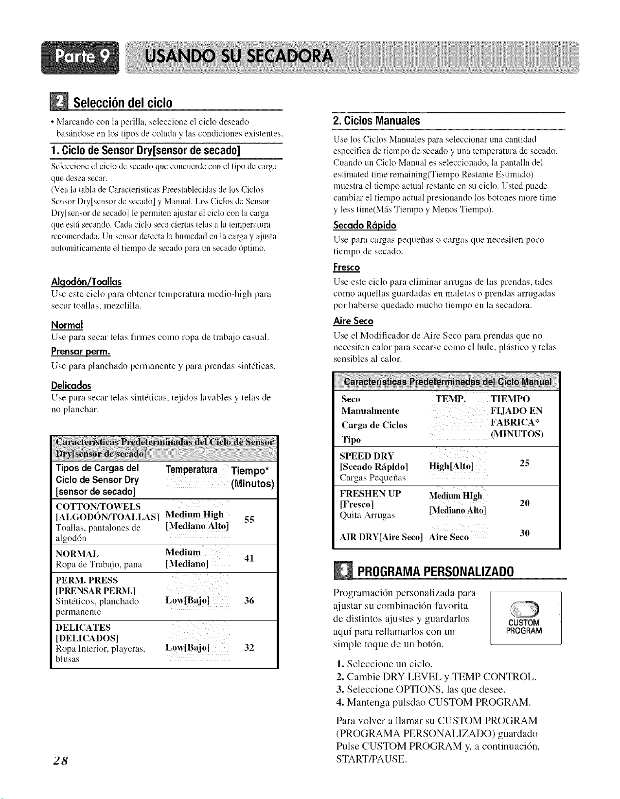
Selecci6ndel ciclo
• Marcando con la perilla, seleccione el ciclo deseado
bas_.ndoseen los tipos de colada y las condiciones existentes.
1. Ciclo de Sensor Dry[sensor de secado]
Seleccione el ciclo de secado que concuerde con el tipo de carga
que desea secar.
(Vea la tabla de Caracter/sticas Preestablecidas de los Ciclos
Sensor Dry[sensor de secado] y Manual. Los Ciclos de Sensor
Dry[sensor de secado] le permiten ajustar el ciclo con la carga
que estfi secando. Cada ciclo seca ciertas telas a la temperatura
recomendada. Un sensor detecta la humedad en la carga y ajusta
automfiticamenteel tiempo de secado para un secado 6ptimo.
Algod6n/Toallas
Use este ciclo para obtener temperatura medio-high para
secar toallas, mezclilla.
Normal
Use para secar telas finnes como ropa de trabajo casual.
Prensar perm.
Use para planchado permanente y para prendas sintdticas.
Delicados
Use para secar telas sintdticas, tejidos lawtbles y telas de
no planchar.
Tipos de Cargas del
Ciclo de Sensor Dry
[sensor de secado]
COTTON/TOWELS
[AL(;OI)0N/TOALLAS]
Toallas, pantalones de
algod6n
NORMAL
Ropa de Trabajo, pana
PERM. PRESS
[PRENSAR PERM.]
Sintdticos, planchado
permanente
DELICATES
[DELICADOS]
Ropa Interior, playeras,
blusas
Temperatura Tiempo*
(Minutos
Medium High 55
[Mediano Alto]
Medium 41
[Mediano]
Low[Bajo] 36
Low[Baj0] 32
28
2. Ciclos Manuales
Use los Ciclos Manuales para seleccionar una cantidad
especifica de tiempo de secado y una temperatura de secado.
Cuando un Ciclo Manual es seleccionado, la pantalla del
estimated time remaining(Tiempo Restante Estimado)
muestra el tiempo actual restante en su ciclo. Usted puede
cambiar el tiempo actual presionando los botones more time
y less time(Mils Tiempo y Menos Tiempo).
Secado Rdpido
Use para cargas pequefias o cargas clue necesiten poco
tiempo de secado.
Fresco
Use este ciclo para eliminar arrugas de las prendas, tales
como aquellas guardadas en maletas o prendas arrugadas
por haberse quedado mucho tiempo en la secadora.
Aire Seco
Use el Modificador de Aire Seco para prendas que no
necesiten calor pare secarse colno el hule, plgstico y telas
sensibles al calor.
Seco TEMP. TIEMPO
Manualmente FIJADO EN
Carga de Ciclos FABRICA*
Tipo (MINUTOS)
SPEED DRY
[Secado Rfipido] High[Alto] 25
Cargas Pequefias
FRESHEN UP Uedi,,m
High
]Fresco] ---- 20
Quita Arrugas [MedianoAlto]
30
AIR DRY[Airc Seco] Aire Seco
PROGRAMAPERSONALIZADO
Programacidn personalizada para
ajustar su combinacidn favorita
de distintos ajustes y guardarlos
aqui para rellamarlos con un
simple toque de un botdn.
CUSTOM
PROGRAM
Para volver a llamar su CUSTOM PROGRAM
(PROGRAMA PERSONALIZADO) guardado
Pulse CUSTOM PROGRAM y, a continuacidm
START/PAUSE.
1. Seleccione un ciclo.
2. Cambie DRY LEVEL y TEMP CONTROL.
3. Seleccione OPTIONS, las que desee.
4. Mantenga pulsdao CUSTOM PROGRAM.
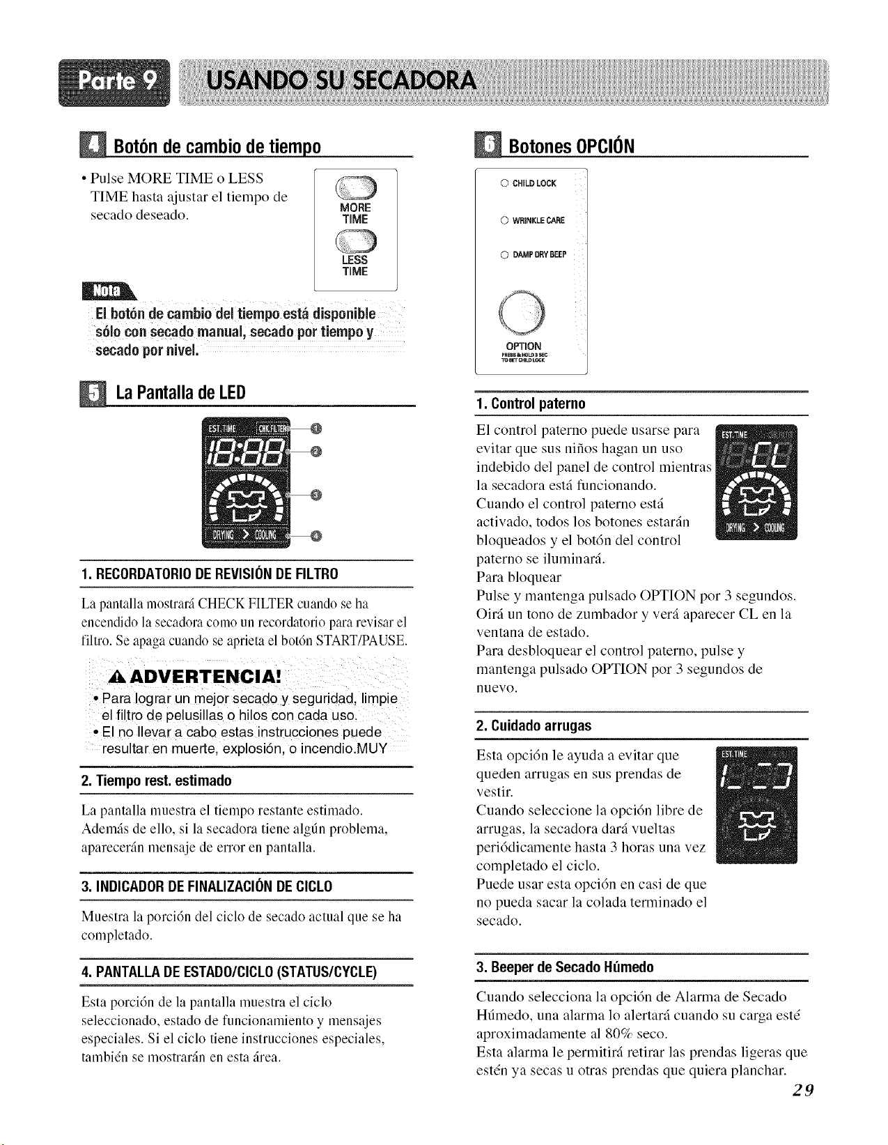
Bot6nde cambiode tiempo
• Pulse MORE TIME o LESS
TIME hasta ajustar el tiempo de
secado deseado.
MORE
TiME
LESS
TiME
El bot6n de cambio del tiempo est_ disponibie
s61ocon secado manual, secado per tiempo y
secado per nivel,
LaPantalladeLED
1. RECORDATORIODE REVISIONDE FILTRO
La pantalla mostrar_ CHECK FILTER cuando se ha
encendido la secadora como un recordatorio para revisar el
filtro. Se apaga cuando se aprieta el bot6n START/PAUSE.
• Para !ograr un mejor secado y seguridad, limpie
el filtro de pelusillas o hilos cen cada use,
°E! no Ilevar a cabo estas instrucciones puede
resultar en muerte, explosi6n, o incendioMUY
2. Tiempo rest. estimado
La pantalla muestra el tiempo restante estimado.
Ademfis de ello, si la secadora tiene algdn problema,
aparecerfin mensaje de error en pantalla.
3. INDICADORDE FINALIZACIONDE CICLO
Muestra la porci6n del ciclo de secado actual que se ha
completado.
4. PANTALLADE ESTADO/CICLO(STATUS/CYCLE)
Esta porci6n de la pantalla muestra el ciclo
seleccionado, estado de funcionamiento y mensajes
especiales. Si el ciclo tiene instrucciones especiales,
tambi_n se mostrarSn en esta 5tea.
BotonesOPCION
0 CHILD LOCK
0 WRINKLE CARE
0 DAMPDRYBEEP
OPTION
pRBSSt_LD _ SEC
TO_'r CHILDLOCK
1. Control paterno
El control paterno puede usarse para
evitar que sus nifios hagan un uso
indebido del panel de control mientras
la secadora est,fi funcionando.
Cuando el control paterno est,fi
activado, todos los botones estar,fin
bloqueados y el bot6n del control
paterno se iluminar,fi.
Para bloquear
Pulse y mantenga pulsado OPTION por 3 segundos.
Oir,fi un tono de zumbador y ver,-i aparecer CL en la
ventana de estado.
Para desbloquear el control paterno, pulse y
mantenga pulsado OPTION por 3 segundos de
nuevo.
2. Cuidado arrugas
Esta opci6n le ayuda a evitar que
queden arrugas en sus prendas de
vestir.
Cuando seleccione la opci6n libre de
arrugas, la secadora dar,-ivueltas
peri6dicamente hasta 3 horas una vez
completado el ciclo.
Puede usar esta opci6n en casi de que
no pueda sacar la colada terminado el
secado.
3. Beeper de Secado Humedo
Cuando selecciona la opci6n de Alarma de Secado
Hdmedo, una alarma 1o alertar,-i cuando su carga est(
aproximadamente al 80% seco.
Esta alarma le permitir,fi retirar las prendas ligeras que
est(n ya secas u otras prendas que quiera planchar.
29
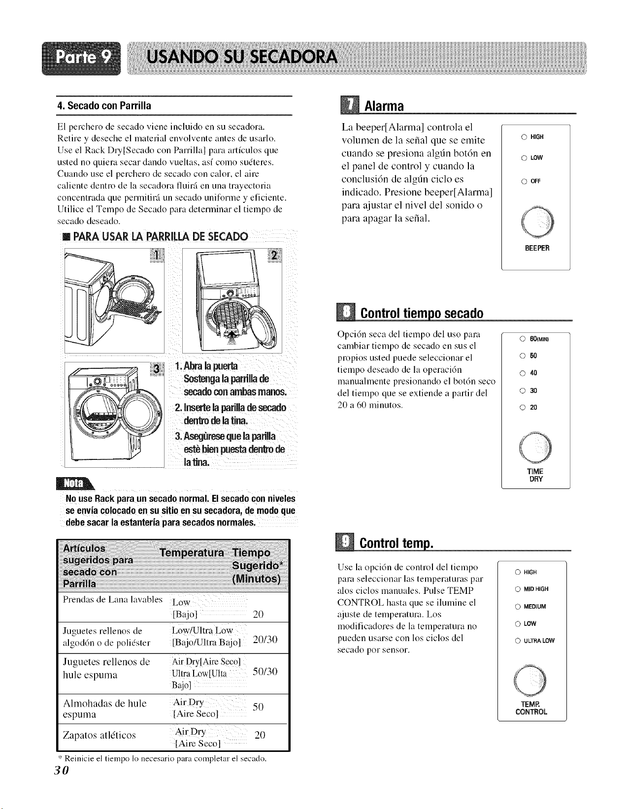
4. Secado con Parrilla
Alarma
El perchero de secado viene incluido en su secadora.
Retire y deseche el material envolvente antes de usarlo.
Use el Rack Du[Secado con Parrilla] para artfculos que
usted no quiera secar dando vueltas, asf colno sudteres.
Cuando use el perchero de secado con calor, el aire
caliente dentro de la secadora fluini en una trayectoria
concentrada que permitir_ un secado uniforlne y eficiente.
Utilice el Tempo de Secado para deterlninar el tielnpo de
secado deseado.
m PARAUSAR LA PARRELADE SECADO
tma!a rta
- ........ Sostenga la parri[[ade
seeadoconambasmanos'
2,Insertea pariUadesecado
dentrOde Jatina'
estb bienpuestadenkode
latina,
NOuse Rackparaun secadonormal,Elsecadoconniveles
se enviaco!ocadoen susitio en su secadora,de modoque
debe sacar la estanteriapara secadosnormales,
La beeper[Alarma] controla el
volumen de la serial que se emite
cuando se presiona algdn botdn en
el panel de control y cuando la
conclusidn de algtln ciclo es
indicado. Presione beeper[Alarma]
para ajustar el nivel del sonido o
para apagar la serial.
@ HiGH
O LOW
0 OFF
BEEPER
Controltiemposecado
Opcidn seca del tiempo del uso para
calnbiar tiempo de secado en sus el
propios usted puede seleccionar el
tiempo deseado de la operaci6n
manuahnente presionando el bot6n seco
del tielnpo que se extiende a partir del
20 a 60 lninutos.
C) 601MIN)
© 5O
© 4O
© 30
© 20
TiME
DRY
Prendas de Lana lavables Low
[Bajo] 20
Juguetes rellenos de L0w/Ultra LOw
algoddn o de polidster [Bajo/U!traBajo] 20/30
Juguetes rellenos de Air Dry[Aire Sec0]
hule espuma Ultra Low[U!ta 50/30
gajol
Almohadas de hule Air Dry 50
espuma [Aire Seco]
Zapatos atldticos Air Dry 20
[Aim Seco]
* Reinicie el tiempo 1o necesario para completar el secado.
3O
Controltemp.
Use la opcidn de control del tiempo
para seleccionar las temperaturas par
alos ciclos manuales. Pulse TEMP
CONTROL hasta que se ilumine el
ajuste de temperatura. Los
modificadores de la telnperatura no
pueden usarse con los ciclos del
secado por sensor.
Q HiGH
@ MiD HIGH
© MEDtUM
0 LOW
(3 ULTRA LOW
TEMP.
CONTROL
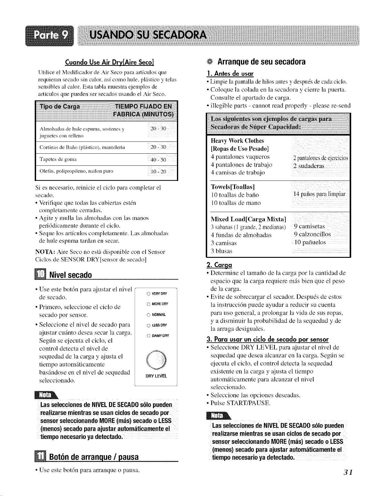
Cuando Use Air Dry[Aire Seco]
Utilice el Modificador de Air Seco para artfculos que
requieran secado sin calor, as/cored hule, pl4stico y telas
sensibles al calor. Esta tabla muestra ejelnplos de
articulos que pueden set secados usando el Air Seco.
Ahnohadas de hule espuma, sostenes y 20:30
juguetes con relleno
Cortinas de Bafio (pl:istico), mantelerla 20 - 30
Tapetes de goma 40 - 50
Olefin, polipropileno, nailon puro i0 2 20
Si es necesario, reinicie el ciclo para completar el
secado.
• Verifique que todas las cubiertas est&l
completamente cerradas.
• Agite y mulla las almohadas con las manos
peri6dicamente durante el ciclo.
• Seque los artfculos completamente. Las almohadas
de hule espuma tardan en secar.
NOTA: Aire Seco no esth disponible con el Sensor
Ciclos de SENSOR DRY[sensor de secado]
NJvelsecado
• Use este bot6n para ajustar el nivel
de secado.
• Primero, seleccione el ciclo de
secado por sensor.
• Seleccione el nivel de secado para
ajustar cufinto desea secar la carga.
Segt]n se ejecuta el ciclo, el
control detecta el nivel de
sequedad de la carga y ajusta el
tiempo automfiticamente
basfindose en el nivel de sequedad
seleccionado.
O VERY DRY
© MORE DRY
O NORMAL
© LESS DRY
0 DAMP DRY
DRYLEVEL
Las se!ecciones de NIVEL DE SEGADOs61opueden
realizarse mientras se usan ciclos de secado por
sensor seleccionando MORE(mils) secado o LESS
(mends) secado para ajustar automfiticamente el
tiempo necesario ya detectado.
BotOnde arranque / pausa
• Use este botdn para arranque () pausa.
Arranque de seu secadora
|. Antes de usar
• Limpie la pantalla de hilos antes y despuds de cada ciclo.
• Coloque la colada en la secadora y cierre la puerta.
Consulte el apartado de carga.
• illegible parts - cannot read properly - please re-send
Heavy Work Clothes
[Ropas de Uso Pesado]
4 pantalones vaqueros
4 pantalones de trabajo
4 camisas de trabajo
2 pantalones de ejercicios
2 sudaderas
Towels[Toallas]
10 toallas de bafio
10 toallas de mano
14paiios para limpiar
Mixed Load[Carga Mixta]
3 sabanas (1 grande. 2 medianas,
4 fundas de almohadas
3 camisas
3 blusas
9 camisetas
9 calzondllos
10 pafiuelos
2. Carga
• Determine el tamafio de la carga por la cantidad de
espacio que la carga requiere mils bien que el peso
de la carga.
• Evite de sobrecargar el secador. Despuds de estos
la instrucci6n puede ayudar a reducir su cuenta
para uso general, a prolongar la vida de sus ropas,
y a disminuir la probabilidad de la sequedad y de
la arruga desiguales.
3. Para usar un ciclo de secado por sensor
• Seleccione DRY LEVEL para ajustar el nivel de
sequedad que desea alcanzar en la carga. Segt]n se
ejecuta el ciclo, el control detecta la sequedad
existente en la carga y ajusta el tiempo
automfiticamente para alcanzar el nivel
seleccionado.
• Seleccione las opciones deseadas.
• Pulse START/PAUSE.
Las se!ecciones de NIVEL DE SEGADOs61opueden
rea!izarse mientras se usan ciclos de secado por
sensor seleccionando MORE (mils) secado o LESS
(mends) secado para ajustar automfiticamente el
tiempo necesario ya detectado.
31
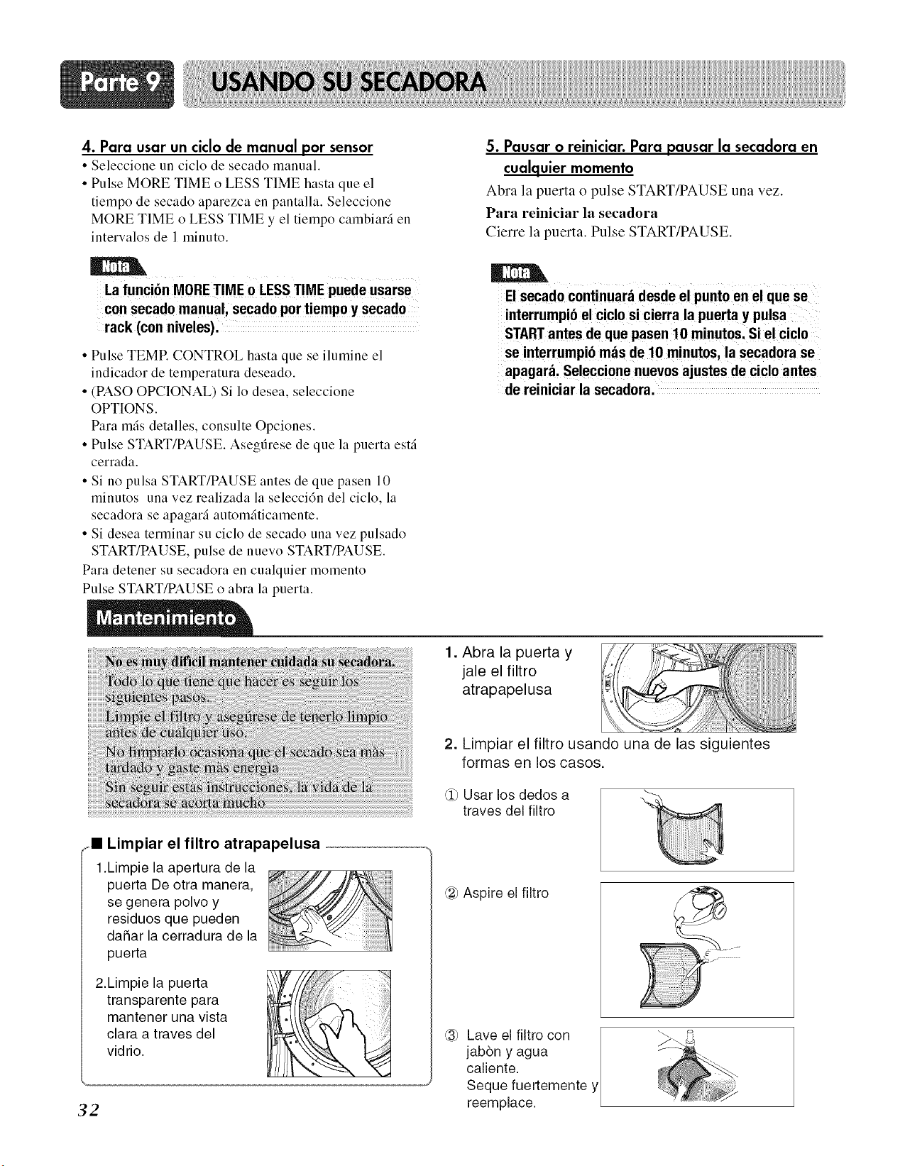
4. Para usar un ciclo de manual por sensor
• Seleccione un ciclo de secado manual.
• Pulse MORE TIME o LESS TIME hasta que el
tiempo de secado aparezca en pantalla. Seleccione
MORE TIME o LESS TIME y el tiempo cambiarfi en
intervalos de 1 minuto.
5. Pausar o reiniciar. Para pausar la secadora en
cualquier momento
Abra la puerta o pulse START/PAUSE una vez.
Para reiniciar la secadora
Cierre la puerta. Pulse START/PAUSE.
La funci6n MORE TIME 0 LESS TIME puede usarse
con secado manual, secado por tiempo y secado
rack (con niveles).
• Pulse TEMR CONTROL hasta que se ilumine el
indicador de temperatura deseado.
• (PASO OPCIONAL) Si 1o desea, seleccione
OPTIONS.
Para mils detalles, consulte Opciones.
• Pulse START/PAUSE. Asegfirese de que la puerta estfi
cerrada.
• Si no pulsa START/PAUSE antes de que pasen 10
minutos una vez realizada la seleccidn del ciclo, la
secadora se apagarfi automfiticamente.
• Si desea terminar su ciclo de secado una vez pulsado
START/PAUSE, pulse de nuevo START/PAUSE.
Para detener su secadora en cualquier momento
Pulse START/PAUSE o abra la puerta.
El secado continuara desde el punto en el que se
interrumpio el ciclo si cierra la puerta y pulsa
STARTantes de que pasen 10 minutos. Si el ciclo
se interrumpio mas de 10 minutos, la secadora se
apagar& Seleccione nuevos ajustes de ciclo antes
de reiniciar la secadora.
1. Abra la puerta y
jale el filtro
atrapapelusa
32
2. Limpiar el filtro usando una de las siguientes
_ll Limpiar el filtro atrapapelusa
1.Limpie la apertura de la
puerta De otra manera,
se genera polvo y
residuos que pueden
dafiar la cerradura de la
puerta
2.Limpie la puerta
transparente para
mantener una vista
clara a traves del
vidrio.
formas en los casos.
@ Usar los dedos a
traves del filtro
_) Aspire el filtro
_ Lave el filtro con [
jabbn y agua /
ca[iente. /
Seque fuertemente y
reemp ace.
Consejosparalasolucidnde problemas
Ahorretiempoydinero!Primeroreviselastablasenlassiguientes
pfiginasyquizasnonecesiteIlamaraservicio.
1.Problema: Mi Secadora no Arranca
• Est_i la Secadora conectada? Confirme que e! enchufe de !a secadora est6 completamente insertado en el tomacorriente
. del cuarto de lavado.
• Est_iel fusible fundido, o el disyuntor Vefifique la caja de fnsibles/disyuntores del cuarto de lavado de su casa y cambie los fusibles
disparado? o reconecte los disyuntores. (IMPORTANTE: generalmente las secadoras eldctricas
usan dos tusibles o disyuntores.)
2.Problema: Mi Secadora no Calienta
' Est fie! fusible fundido; o e! disyuntor Si el fusible estfi fundido o el disyuntor disparado, la secadora quizfis de vue!tas per0 no
disparado? calienta. Verifique la caja de fusibles!disyuntores del Cuaxto de lavado de su casa y cambie
!os fusib!es o rec0necte los disyunteres, (IMPORTANTE: generalmente !as secadoras
. e!6ctricas usma dos fusib!es o disyuntores,)
• Estfi el suministro o servicio de gas Confirme que Ias vfilvulasde apagado de gas de la casa y de la secadora estdn completamenteabiertas.
bloqueado o apagado?
3.Problema: Hay Manchas de Grasa en la Ropa
, Sigui6 usted las instrucciones del C0nfirme y siga !as instrucci0nes pr0vistas con e! suavizante de te!as.
empaque del Suavizante de telas?
• Est_i usted secando ropa limpia y ropa Asegtiresedeusar sus_adora para secarprendaslimpi_ssolamente,debidoa queprcndassuciaspucden
sucia juntas? mancharlaropa limpia que estfinen la mismacarga o colocadasposteriormenteen el tamborde lavado.
, Estaban sus prenda s Completamente
!impias?
Las manchas en !a ropa seca son manchas que no fueron eliminadas durante el proces0 de !avado.
Por favor revise y confirme que se est_n siguiendo las instrucciones de lavado y que la
ropa est_ quedando Comp!etamente !impia,
4. Problema: Mi Secadora muestra "Error"
Se muestra Cuando el Thermistor no esta Conectada. En este caso, el thermistor
. debe se!i reemp!azad0y !!amar a! _entr0 de servici0,
tE2
Se muestra cuando el thermistor es muy colto.
En este caso, el thennistator debe set reemplazado y llamar al centro de servicio.
33
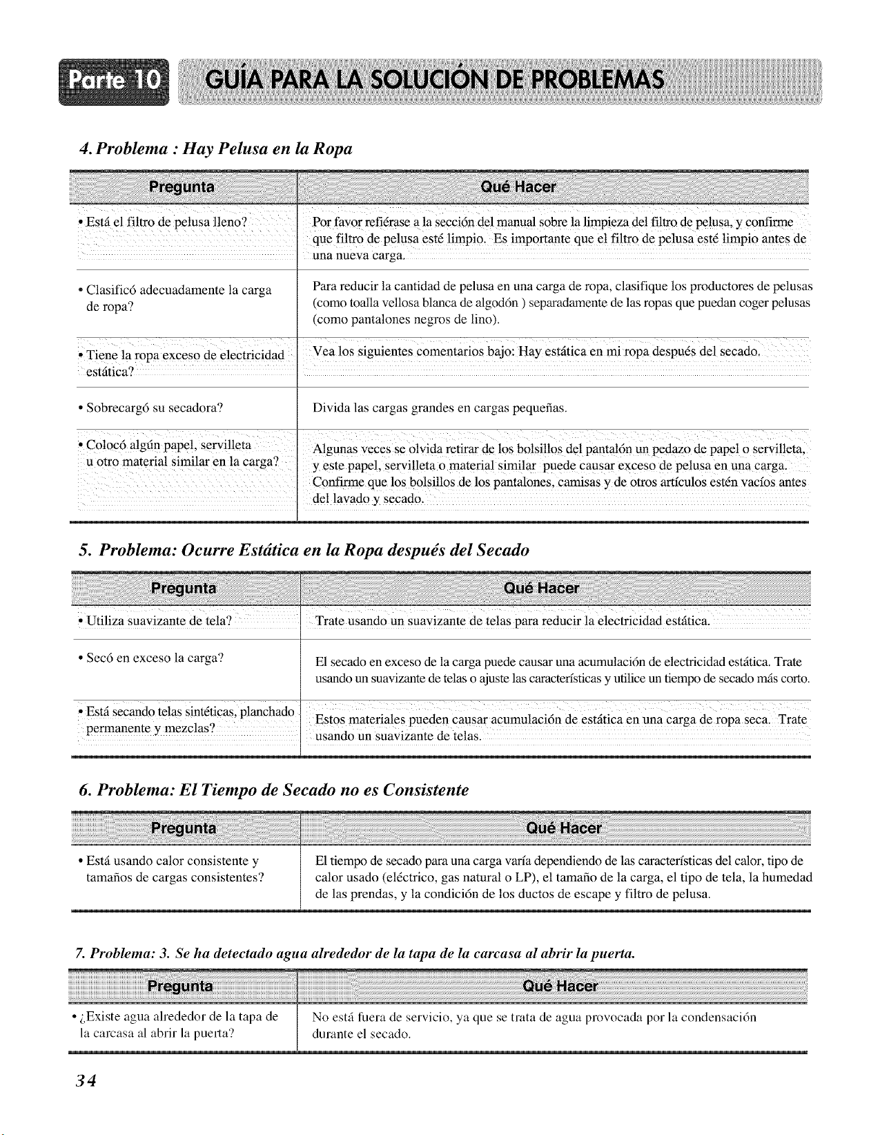
4. Problema : Hay Pelusa en la Ropa
, Est_ el f!ltro de pelusa lleno? Pot fayor ref!6rase a la secci6n de! manua! sobre la !impieza de! filtro de pe!usa, y €onfirme
que fi!tr0 de pelusa est_ !impio. Es importante que e! fi!tro de pe!usa est6 !impi0 Htes de
una nue_a carga.
para reducir la cantidad de pelusa en una carga de ropa, clasifique los productores de pelusas
* Clasific6 adecuadamente la carga
de ropa? (como toalla vellosa blanca de algod6n ) separadamente de las ropas que puedan coger pelusas
(como pantalones negros de lino).
' Tiene la ropa exceso de electricidad Vea !os siguientes comentarios bajo: Hay estfitica en mi ropa despu_s del secado.
est_tica? I
• Sobrecarg6 su secadora? Divida las cargas grandes en cargas pequefias.
C!oc gn !, efl!et,o 6al fi pape srv a
A!gunaS veCes se olyida refirar de los bo!si!!os de! pa_ta!6n un pedaZo de Pape! 0 Servi!!em;
u otto material Similar en la carga? y este papel, servil!eta o material similar puede causar exceso de pe!usa en una cargal
C0nfirme que !0S b°!si!los de !os panta!ones, c_sas y de otros artfcu!os est6n ratios antes
de! !avado y secado.
5. Problema: Ocurre Estdtica en la Ropa despu_s del Secado
• Utiliza suavizante de tela? Trate usando un suavizante de te!as para reducir !a e!ectricidad est_itica,
• Sec6 en exceso la carga? E1secado en exceso de la carga puede causar una acumulaci6n de electricidad esffttica. Trate
usando un suavizante de telas o ajuste las caxactedsticas y utilice un tiempo de secado m_iscorto.
• Estfi Secando telas Sint6ticaslplanchado
Estos materiales pueden Causar acumulaci6n de estfitica en una Carga de ropa Secal Trate
permanente y mezclas? Usand0 Un suavizante de telas.
6. Problema: El Tiempo de Secado no es Consistente
• Estfi usando calor consistente y
tamafios de cargas consistentes?
El tiempo de secado para una carga varfa dependiendo de las caractedsticas del calor, tipo de
calor usado (eldctrico, gas natural o LP), el tamafio de la carga, el tipo de tela, la humedad
de las prendas, y la condici6n de los ductos de escape y filtro de pelusa.
7. Problema: 3. Se ha detectado agua alrededor de la tapa de la carcasa al abrir la puerta.
_re_
i,Existe agua ahededor de la tapa de [ No estg fuera de servicio, ya que se trata de agua provocada por la condensacidn
la carcasa al abrir la puerta? durante el secado.
34
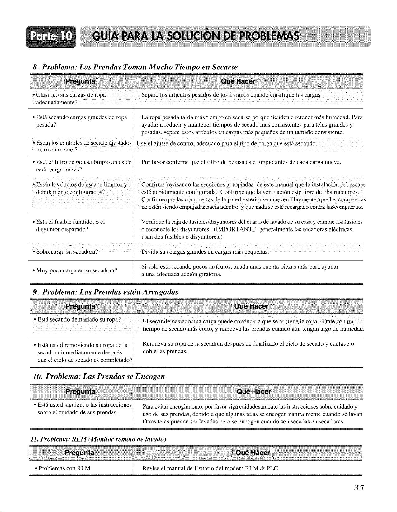
8. Problema: Las Prendas Toman Mucho Tiempo en Secarse
, C!asific6 sus cargas de ropa Separe !0S a_fcu!0s pesad0s de !0S !iyian0s Cuand0 C!asifique !as _argas,
adecuadamente?
• Esti secando cargas grandes de ropa La ropa pesada tarda mils tiempo en secarse porque tienden a retener mis humedad. Para
pesada? ayudar a reducir y mantener tiempos de secado mls consistentes para telas grandes y
pesadas, separe estos artfculos en cargas mis pequefias de un tamafio consistente.
' Estin !os Controles de secado ajustados Use e! ajuste de contr0! adeCUad0 para e! tip0 de Carga que est_ secand0:
correctamente ?
• Esti el filtro de pelusa limpio antes de Por favor confirme que el filtro de pelusa estd limpio antes de cada carga nueva.
cada carga nueva?
, Estin !0S duct0s @escape limpios y Confirme revisand0 !as secciones aPropiadas de este manua! que la instalacidn de! escape
debidarnente Configurados ? est_ debidamente configm-ada, Confirme que !a venti!acidn estd !ibre de 0bstmcci0nes .
Confirme que las compuertas de la pared exterior se mueven libremente, que las Compuertas
no estdn siendo empujadas hacia adentro, y que nada se estd recargado con_ra las compuertas.
• Esti et fusible fundido, o el Verifique la caja de fusibles/disyuntores del cuarto de lavado de su casa y cambie los fusibles
disyuntor disparado? o reconecte los disyuntores. (IMPORTANTE: generalmente las secadoras el@tricas
usan dos fusibles o disyuntores.)
I
• Sobrecarg6 su secadora? ' Divida Sus cargas grandes en cargas mis pequefias.
Si s61o esti secando pocos artfculos, afiada unas cuenta piezas mis para ayudar
• Muy poca carga en su secadora? a una adecuada acci6n giratoria.
9. Problema: Las Prendas estdn Arrugadas
' Esti secando demasiado Su ropa? E! Secar demasiado un a Cm'ga puede C0nducir aque Searrugue !a r0pa, Trate Con un
• tiempo de secado mis Corto, y remueva las prendas cuando afin tengan algo de humedad.
• Esti usted removiendo su ropa de la Remueva su ropa de la secadora despu_s de finalizado el ciclo de secado y cuelgue o
secadora inmediatamente despuds doble las prendas.
que el ciclo de secado es completado?
10. Problema: Las Prendas se Encogen
• Esti usted siguiendo las instrucciones
sobre el cuidado de sus prendas.
Para evitar encogimiento, por favor siga cuidadosamente las instmcciones sobre cuidado y
uso de sus prendas, debido a que algunas telas se encogen naturalmente cuando se lavan.
Otras telas pueden ser lavadas pero se encogen cuando son secadas en secadoras.
11. Problema: RLM (Monitor remoto de lavado)
• Problemas con RLM Revise el manual de Usuario del modem RLM & PLC.
35
Su Secadora LG sera reparada o reemplazada, a opci6n de LG, si demuestra estar defectuosa en material o mano de
obra bajo uso normal, durante el periodo de garantia ("Periodo de garantia) que se menciona a continuaci6n, efectiva
desde la fecha (Fecha de Compra) original de compra del producto. Esta garantia solo es valida para el comprador
original del producto yes efectiva solo en los Estados Unidos, incluyendo Alaska, Hawai y otros territorios de EE.UU..
PERIODO DE GARANTIA
MANO DE OBRA: Un Afio desde la fecha de compra
PARTES: Un Afio desde la fecha de compra
Las unidades reemplazadas y las partes reparadas
pueden ser nuevas o remanufacturadas en la fabrica.
Las unidades reemplazadas y las partes reparadas
estan garantizadas pot la porcion restante del periodo
de garantia de la unidad original.
COMO SE MANEJA EL SERVIClO
Servicio a Domicilio: Por favor conserve el recibo
Con fecha o boleto de entrega como evidencia de la fecha de
compra como prueba de la garantfa, y proporcione una copia
del recibo de compra a la persona de servicio en el momento en
que un servicio sea proporcionado
Por favor Ilame al: 1-800-243-0000 y escoja la opeion
adecuada para ubiear el Centro Autorizado de Servicio LG
mas cercano, (los telefonos son contestados Las 24 horas, los
365 dfas del aho)
O vivite nuestro sitio web en: http//www.lgservice.com
ESTA GARANTIA ESTA EN LUGAR DE CUALOUIER OTRA GAERANTIA, EXPRESA O IMPLICADA,
INCLUYENDO SIN NINGUNA LIMITACION, CUALQUIER GARANTIA DE COMPRA O ADAPTACION PARA UN
PROPOSITO PARTICULAR, HASTA EL PUNTO OUE CUALQUIER GARANTIA ES REQUERIDA POR LEY, ES
LIMITADA EN DURACION AL PERIODO DE GARANTIA, NI EN FABRICANTE (LG) NI SUS DISTRIBUIDORES EN
EE.UU SE HACEN RESPONSABLES POR NINGUN DANO INCIDENTAL, CONSECUENTE, INDIRECTO, ESPECIAL O
PUNITIVO DE CUALQUIER NATURALEZA, INCLUYENDO SIN LIMITACION, PERDIDA DE GANANCIAS, O
CUALQUIER OTRO DANO YA SEA BASADO EN CONTRATO, AGRAVIO O DE OTRA MANERA.
Algunos estados no permiten la exclusi6n o limitaci6n de da_os incidentales o consecuentes o limitaciones de cuanto dura
una garantia, asi que las exclusiones o limitaciones mencionadas anteriormente pueden no aplicar a usted. Esta garantia
le da derechos legales especificos y tambien puede tener otros derechos que varian de estado a estado.
Esta garantia limitada no aplica a:
Viajes de servicio para entregar, recoger, y/o instalar el producto, instruir, o reemplaFar fusibles o corregir cableado, o
correcci6n de reparaciones no autorizadas.
DaSos o problemas de operaci6n que resulten de mal uso, abuso, operaci6n fuera de especificaciones ambientales o
contraria a los requerimientos o precauciones en el manual de operaci6n, accidente, bicho, fuego, inundaci6n,
instalaci6n inadecuada, actos de dios, modificaciones o alteraciones no autorizadas, corriente o voltaje incorrectos, o
uso comercial o cualquier otro uso diferente al intencionado.
NUMEROS DEL CENTRO INTERACTIVO DE CLIENTES
Para obtener asistencia a clientes, informaci6n del
producto, o distribuidor o la Iocalidad de un centro
autorizado de servicio:
Lame al 1-800-243-0000 (24 horas al dia, 365 dias al
aSo) y seleccione la opci6n adecuada del ment3.
PARA CONTACTAR A LG ELECTRONICS POR CORREO:
Centro Interactivo del Cliente LG
P.O. Box 240007
201 James Record Road
Huntsville, Alabama 35824
ATTN: CIC
36