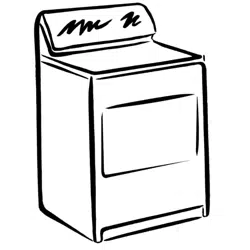
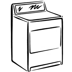
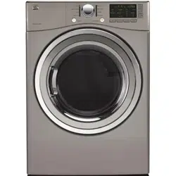
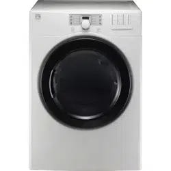
Kenmore 79680272900 dryer
Product's Documents
Below are documents related to this product, you can read online or download:
- Owner's manual - (English) Read Online | Download pdf
CONTENTS
OPTIONAL ACCESSORIES
Optional Accessories Stacking Kit Installation Pedestal Installation Side venting kit installation
WARRANTY
Your Safety and the safety of others is very important.
We have provided many important safety messages in this manual and on your appliance. Always read and obey all safety messages.
This is the safety alert symbol.
This symbol alerts you to potential hazards that can kill or hurt you and others.
All safety messages will follow the safety alert symbol and either the word DANGER or WARNING.
These words mean:
DANGER: Youcanbe killed or seriously injured if you don't immediately follow instructions.
WARNING: You can be killed or seriously injured if you don't follow instructions.
All safety messages will tell you what the potential hazard is. tell you how to reduce the chance of injury. and tell you what can happen if the instructions are not followed.
Do not install a clothes dryer with flexible plastic venting materials. if flexible metal (foil type) duct is installed. it must be of a specific type identified by the appliance manufacturer as suitable for use with clothes dryers.
Flexible venting materials are known to collapse. be easily crushed. and trap lint. These conditions will obstruct clothes dryer airflow and increase the risk of fire.
Do not store or use gasoline or other flammable vapors and liquids in the vicinity of this appliance or any other appliances.
1. Do not try to light a match or cigarette. or turn on any gas or electrical appliance.
2. Do not touch any electrical switches.
Do not use any phone in your building.
3. Clear the room. building. or area of all occupants.
4. Immediately call your gas supplier from neighbor's phone.
Follow the gas supplier's instructions carefully.
5. if you cannot reach your gas supplier. call the fire department.
WARNING:
• Read all instructions before using the dryer.
• Before use. the dryer must be properly installed as described in this manual.
• Do not place items exposed to cooking oils in your dryer. Items contaminated with cooking oils may contribute to a chemical reaction that could cause a load to catch fire.
• Do not dry articles that have been previously cleaned in. washed in. soaked in. or spotted with gasoline. dry-cleaning solvents. or other flammable or explosive substances as they give off vapors that could ignite or explode.
• Do not reach into the dryer if the drum or any other part is moving.
• Do not repair or replace any part of the dryer or attempt any servicing unless specifically recommended in this Use and Care Guide or in
To reduce the risk of fire. electric shock. or injury to persons when using this appliance.
• Do not allow children to play on or in the dryer. Close supervision of children is necessary when the dryer is used near children.
• Do not use fabric softeners or products to eliminate static unless recommended by the manufacturer of the fabric softener or product.
• Do not use heat to dry articles containing foam rubber or similarly textured rubber-like materials.
• Keep area around the exhaust opening and adjacent surrounding areas free from the accumulation of lint. dust. and dirt.
• The interior of the dryer and exhaust vent should be cleaned periodically by qualified service personnel.
• Do not install or store the dryer where it will be exposed to the weather.
• Always check the inside of the dryer for foreign objects.
• Clean lint screen before or after each load.
CALIFORNIA SAFE DRINKING WATER AND TOXIC ENFORCEMENT ACT
This act requires the governor of California to publish a list of substances known to the state to cause cancer. birth defects. or other reproductive harm and requires businesses to warn customers of potential exposure to such substances.
Gas appliances can cause minor exposure to four of these substances. namely benzene. carbon monoxide. formaldehyde. and soot. caused primarily by the incomplete combustion of natural gas or LP fuels.
Properly adjusted dryers will minimize incomplete combustion.
Exposure to these substances can be minimized further by properly venting the dryer to the outdoors.
This appliance must be grounded.
In the event of malfunction or breakdown. grounding will reduce the risk of electric shock by providing a path of least resistance for electric current.
This appliance must be equipped with a cord having an equipment-grounding conductor and a grounding plug. The plug must be plugged into an appropriate outlet that is properly installed and grounded in accordance with all local codes and ordinances.
WARNING: Improper connection of the equipment-grounding conductor can result in a risk of electric
WARNING: To reduce the risk of fire. electric shock. or injury to persons when using this appliance.
The exhaust duct
SAFETY INSTRUCTIONS FOR CONNECTING ELECTRICITY
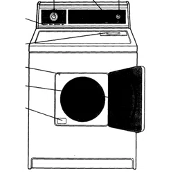
There are several important components that are referenced in this manual.
EASY-TO-USE CONTROL PANEL Rotate the Cycle Selector Knob to select the desired dry cycle. Add cycle options or adjust settings with the touch of a button.
TIME AND STATUS DISPLAY The easy-to-read LED display shows cycle status and estimated time remaining.
CYCLE MODIFIERS Adjust the cycle defaults such as temperature and dryness level with the touch of a button.
NOTE: Not all settings are available for all cycles.
CHECK VENT (Duct Blockage Sensing System) The Check Vent (Duct blockage sensing system) detects and alerts you to blockages in the exhaust system that reduce airflow from the dryer.
Maintaining clean exhaust system ducts improves operating efficiency and helps minimize service calls. saving you money.
DOUBLE-COATED STEEL DRUM It is coated with one metal coating and the other polymer coating in order to guarantee high durabili ty and the long life.
EASY-ACCESS REVERSIBLE DOOR Wide-opening. see-through glass door provides easy access for loading and unloading.
Door swing can be reversed to adjust for installation location.
FRONT-MOUNT LINT SCREEN Front-mounted lint screen allows for easy access and cleaning between loads.
LEVELING FEET Four leveling feet (two in front. and two in back) adjust to improve dryer stability on uneven floors.
Power Cord Terminal Block Location Access Panel (Gas Models) (Electric Models)
Gas Connection Location (Gas Models)
Exhaust Duct Outlet
Rear of Dryer
INSTALLATION WITH OPTIONAL PEDESTAL BASE OR STACKING KIT
IMPORTANT: If you are installing your dryer using an optional pedestal base or stacking kit. please refer to the instructions for your pedestal or stacking kit before proceeding with the installation.
Required Dimensions for Installation With Pedestal Required Dimensions for Installation
CONNECTING GAS DRYERS
• Gas supply requirements: As shipped from the factory. this dryer is config ured for use with (NG) natural gas. It can be con verted for use with LP (Liquefied Propane) gas. Gas pressure must not exceed 8-in. water column for (NG). or 13-in. water column for (LP).
A qualified service or gas company technician must connect the dryer to the gas service.
Failure to do so can result in fire. explosion. or death.
• Isolate the dryer from the gas supply system by closing its individual manual shutoff valve during any pressure testing of the gas supply. Failure to do so can result in fire. explosion. or death.
• Supply line requirements: Your laundry room must have a rigid gas supply line to your dryer.
In the United States. an individ ual manual shutoff valve MUST be installed within at least 6 ft. (1.8 m) of the dryer. in accordance with the National Fuel Gas Code ANSI Z223.1. A 1/8-in.
NPT pipe plug must be installed.
Failure to do so can result in fire. explosion. or death.
• If using a rigid pipe. the rigid pipe should be 1/2-in.
IPS. If acceptable under local codes and ordinances and when acceptable to your gas supplier. 3/8-in. approved tubing may be used where lengths are less than 20 ft. (6.1 m). Larger tubing should be used for lengths in excess of 20 ft. (6.1 m). Failure
• To prevent contamination of the gas valve. purge the gas supply of air and sediment before connect ing the gas supply to the dryer. Before tightening the connection between the gas supply and the dryer. purge remaining air until the odor of gas is detected.
Failure to do so can result in fire. explosion. or death.
• DO NOT use an open flame to inspect for gas leaks.
Use a noncorrosive leak detection fluid.
Failure to do so can result in fire. explosion. or death.
• Use only a new AGA- or CSA-certified gas supply line with flexible stainless steel connectors.
Failure to do so can result in fire. explosion. or death.
• Securely tighten all gas connections.
Failure to do so can result in fire. explosion. or death.
• Use Teflon tape or a pipe-joint compound that is insoluble in Liquefied Petroleum (LP) gas on all pipe threads.
Failure to do so can result in fire. explo sion. or death.
• DO NOT attempt any disassembly of the dryer any disassembly requires the attention and tools of an authorized and qualified service person or company.
Failure to do so can result in fire. explosion. or death.
Electrical Requirements for Gas Models Only
• Do not. under any circumstances. cut or remove the third (ground) prong from the power cord. Failure to follow this warning can result in fire. explosion. or death.
• For personal safety. this dryer must be properly grounded.
Failure to follow this warning can result in fire. explosion. or death.
• The power cord of this dryer is equipped with a 3-prong (grounding) plug which mates with a stan dard 3-prong (grounding) wall outlet to minimize the possibility of electric shock hazard from this appli ance. Failure to follow this warning can result in fire.
Where a standard 2-prong wall outlet is encoun tered. it is your personal responsibility and obliga tion to have it replaced with a properly grounded 3-prong wall outlet. Failure to follow this warning can result in fire. explosion. or death.
3-prong grounding type
Ensure proper ground exists before use.
• Installation and service must be performed by a qualified installer. service agency. or the gas supplier.
Failure to do so can result in fire. explosion. or death.
• Use only a new stainless steel flexible connector and a new AGA-certified connector.
Failure to do so can result in fire. explosion. or death.
• A gas shutoff valve must be installed within 6 ft. (1.8 m) of the dryer. Failure to do so can result in fire. explosion. or death.
• The dryer is configured for Natural Gas when shipped from the factory.
Make sure that the dryer is equipped with the correct burner nozzle for the type of gas being used (Natural Gas or Liquefied Petroleum).
Failure to do so can result in fire. explosion. or death.
Connecting the Gas Supply
NOTE: This dryer is configured from the factory set for Natural Gas (NG). If dryer is to be used with LP gas. it must be converted by a qualified service technician.
O Make sure that the gas supply to the laundry room is turned OFF and the dryer is unplugged.
Confirm that the type of gas available in your laundry room is appropriate for the dryer.
Remove the shipping cap from the gas fitting at the back of the dryer. Be careful not to damage the threads of the gas connector when removing the shipping cap.
O Connect the dryer to your laundry room's gas supply using a new flexible stainless steel connector with a 3/8-in. NPT fitting.
NOTE: DO NOT use old connectors.
O Securely tighten all connections between the dryer and your laundry room's gas supply.
Turn on your laundry room's gas supply.
Check all pipe connections (both internal and external) for gas leaks with a noncorrosive leak-detection fluid.
Proceed to Venting Requirements on page
• If necessary. the correct nozzle (for the LP nozzle kit. order part number 4948EL4002B) should be installed by a qualified technician and the change should be noted on the dryer. Failure to do so can result in fire. explosion. or death.
• All connections must be in accordance with local codes and regulations.
Failure to do so can result in fire. explosion. or death.
• Gas dryers MUST exhaust to the outdoors.
Failure to do so can result in fire. explosion. or death.
If your gas dryer is being installed at an elevation above 10. 00 feet. it must be derated by a qualified technician or gas supplier.
CONNECTING ELECTRIC DRYERS
TO help prevent fire. electric shock. serious injury. or death. the wiring and grounding must conform to the latest edition of the National Electrical Code. ANSI/NFPA 70 and all applicable local regulations.
Please contact a quali fied electrician to check your home s wiring and fuses to ensure that your home has adequate elec trical power to operate the dryer.
To reduce the risk of fire. electric shock. or injury to persons when using this appliance. follow basic precautions. including the following:
• Any installation in a manufactured or mobile home must comply with the Manufactured Home Construction and Safety Standards Title 24 CFR. Part 32-80 or Standard CAN/CSAOZ240 MH and local codes and ordinances.
• A 4-wire connection is required for all mobile and manufactured home installations. as well as all new construction after January 1. 1996. Failure to do so can result in fire. explosion. or death.
To reduce the risk of fire. electric shock. or injury to persons when using this appliance. follow basic precautions. including the following:
This dryer must be connected to a grounded metal. permanent wiring system. or an equipment ground ing conductor must be run with the circuit conduc tors and connected to the equipment grounding ter minal or lead on the dryer. Failure to do so can result in fire. explosion. or death.
The dryer has its own terminal block that must be connected to a separate 240 VAC. 60-Hertz. single phase circuit. fused at 30 amperes.
The circuit must be fused on both sides of the line.
Heating elements are avail able for field installation in dryers which are to be connected to an electrical service of a different voltage than that listed on the rating plate. Failure to follow these instructions can result in fire. explosion. or death.
If branch circuit to dryer is 15 ft. (4.5 m) or less in length. use UL (Underwriters Laboratories) listed No.-10 AWG wire (copper wire only). or as required by local codes. If over 15 ft. (4.50 m). use UL-listed No.-8 AWG wire (copper wire only). or as required by local codes. Allow sufficient slack in wiring so dryer can be moved from its normal location when necessary.
Failure to do so can result in fire. explosion. or death.
• The power cord (pigtail) connection between wall receptacle and dryer terminal block IS NOT sup plied with the dryer. Type of pigtail and gauge of wire must conform to local codes and with instruc tions on the following pages. Failure to follow these instructions can result in fire. explosion. or death
• A 4-wire connection is required for all new con struction after January 1. 1996. A 4-wire connection must be used where local codes do not permit grounding through the neutral wire.
Failure to do so can result in fire. explosion. or death.
CONNECTING ELECTRIC DRYERS (cont.)
WARNING
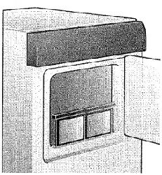
Connect the power cord to the terminal block.
Each colored wire should be connected to same color screw. Wire color indicated on manual is con nected to the same color screw in block. Failure to follow these instructions may result in a short or overload.
Reinstall the terminal block access cover.
Grounding through the neutral conductor is pro hibited for: (1) new branch-circuit installations. mobile homes. (3) recreational vehicles. and (4) areas where local codes prohibit grounding through the neutral conductor.
Three-Wire Power Cord
CHECK YOUR EXHAUST SYSTEM FOR PROBLEMS
The most common cause of dryer problems is poor exhaust venting.
Before you install your new dryer. check the items listed below to make sure you get the best possible performance.
This can save you time and money by reducing cycle times and increasing energy efficiency.
+ DIRTY OR DAMAGED EXHAUST DUCTS.
Lint builds up in exhaust ducts over time. This decreases the airflow and makes the dryer work harder. Visually inspect your ducts from both ends and have them cleaned if they have not been cleaned recently.
WRONG VENT MATERIAL.
Check your vent to make sure it is rigid or semi-rigid metal ducting.
If your venting is plastic flexible foil. have it replace before using the dryer.
Check your vent hood outside. It must be clean and free of lint buildup.
Check the damper and make sure it opens fully and easily.
Measure the length of your exhaust system and count the elbows. Use the chart of page 14 to see if your duct is too long.
If it is too long. have the duct routed to another location that is within the venting guidelines.
DO NOT USE PLASTIC OR FOIL VENTING.
The transition duct from your dryer to the wall must be rigid or semi-rigid metal ducting.
If your old transition duct is plastic or foil. REPLACE IT with semi-rigid metal ducting.
Using the Duct Requirements Chart (below)
DO NOT exceed maximum length for the duct type and number of elbows used.
NOTE: Deduct 6 ft. (1.8 m) for each additional elbow. It is not recommended to use more than four 906elbows.
VENTING THE DRYER (cont.)
Routing and Connecting Ductwork
Follow the guidelines below to maximize drying performance and reduce lint buildup and condensation in the ductwork.
NOTE: Ductwork and fittings are NOT included and must be purchased separately.
• Use 4-in. (102mm) diameter rigid or semi rigid metal ductwork.
• The exhaust duct run should be as short as possible.
• Use as few elbow joints as possible.
• The male end of each section of exhaust duct must point away from the dryer.
• Use duct tape on all duct joints.
• Insulate ductwork that runs through unheated areas in order to reduce condensation and lint buildup on duct surfaces.
• The Total length of flexible metal duct shall not exceed 8 ft.(2.4m)
• In Canada. that only those foil-type flexible ducts. if any. specifically identified for use with the appliance by the manufacturer shall be used. In the United States. that only those foil-type flexible ducts. if any. specifically identified for use with the appliance by the manufacturer and that comply with the Outline for Clothes Dryer Transition Duct. Subject 2158A. shall be used
WARNING" Failure to follow these
IMPORTANT: Failure to exhaust the dryer per the guidelines included within these instructions may result in unsatisfactory dryer performance.
All venting and ductwork beyond the exterior of the dryer is the responsibility of the consumer.
Product failure as a result of improper venting is not covered by the manufacturer's warranty.
WARNING
• Wear gloves during installation.
• Failure to follow these instructions can result in injury.
To ensure that the dryer provides optimal drying performance. it must be level. To minimize vibration. noise. and unwanted movement. the floor must be a level. solid surface.
NOTE: Adjust the leveling feet only as far as necessary to level the dryer. Extending the leveling feet more than necessary can cause the dryer to vibrate.
Level
Leveling Feet
Position the dryer in the final location. Place a level across the top of the dryer.
• All four leveling feet must rest solidly on the floor.
Gently push on the top corners of the dryer to make sure that the dryer does not rock from corner to corner.
OUse a wrench to turn the leveling feet. Turning the foot clockwise lowers the foot and raises the dryer; turning the foot counterclockwise raises the foot and lowers the dryer. Raise or lower the leveling feet until the dryer is level from side-to-side and front-to-back.
Make sure that all 4 leveling feet are in firm contact with the floor.
NOTE: If you are installing the dryer on the optional pedestal. the dryer leveling feet should be fully retracted.
Use the leveling feet on the pedestal to level the dryer.
Open the dryer door.
NOTE: Be sure to support the weight of the door before removing the hinge screws.
Using a Phillips screwdriver. remove the 2 hinge screws that secure the door hinge to the dryer door opening.
Remove the 2 latch screws and the latch from the dryer door opening.
Remove the two screws above and below the latch.
Carefully turn the door up-side-down so the hinge is reversed.
Reattach the door to the opposite side of the door opening.
Reinstall the door latch with the original latch screws.
Replace the remaining screws in the open holes.
Test the door swing to make sure the door moves freely and latches securely.
When the dryer starts. the igniter should ignit the main burner.
NOTE: If all air is not purged from the gas line. the gas igniter may turn off before the main burner ignites. If this happens. the igniter will reattempt gas ignition until all the air is purged from the gas line.
Checking Venting
Vent ductwork should be checked for lint buildup and cleaned at least once per year. If any noticeable reduction in drying performance occurs. check ductwork for obstructions and blockages.
Checking Levelness
Once the dryer is in its final location. recheck the dryer to be sure it is level. Make sure it is level front to back and side to side. and that all 4 leveling feet rest firmly on the floor.
If;qlWARNING" To reduce the risk of fire. electric shock. or injury to persons. read this entire manual. including the Important Safety Instructions. before operating this dryer.
CONTROL PANEL FEATURES
POWER (On/Off) BUTTON
Pressto turn the dryer ON. Press again to turn the dryer OFF.
NOTE: Pressing the Power button during a cycle wilt cancel that cycle and any load settings wilt be lost.
NOTE: If the dryer has been stopped for more than 4 minutes. the dryer will turn off automatically.
OPTION BUTTONS
The option buttons allow you to select additional cycle options. The controls can be locked or unlocked by pressing and holding the Control Lock button for 5 seconds..
MORE TIME and LESS TIME options are not available with sensor dry cycles.
For detailed information about the individual options. please see the following pages.
Use these buttons to adjust the desired cycle options for the selected cycle. The lights above the buttons show the current selection.
TIME AND STATUS DISPLAY
The display shows the estimated time remaining and the cycle status. The display also monitors the vent and lint screen status. See page 22 for a complete description.
LOAD THE DRYER
CLEAN THE LINT FILTER
TURN ON THE DRYER
SELECT A CYCLE
NOTE: Not all options or modifiers are available on all cycles.
SELECT CYCLE OPTIONS
NOTE: Not all options or modifiers are available on all cycles.
BEGIN CYCLE
END OF CYCLE
The cycle guide belew shows the eptiens and recommended fabric types for each cycle. = available eption = default setting
+ Note : This is the default time and actual time will vary depending on the size of the lead and moisture content.
Sensor Dry Cycles
NOTE: To protect your garments. not every dry level. temperature. or option is available with every cycle.
Manual Dry Cycles
• Check all pockets to make sure that they are empty. Items such as clips. pens. coins. and keys can damage both your dryer and your clothes. Flammable objects such as lighters or matches could ignite. causing a fire. Failure to do so can result in fire. explosion. or death.
• Never dry clothes that have been exposed to oil. gasoline. or other flammable substances.
Washing clothes will not completely remove oil residues.
Failure to obey this warning can result in fire. explosion. or death.
Loading Tips
• Combine large and small items in a load.
• Damp clothes will expand as they dry. Do not overload the dryer; clothes require room to tumble dry properly.
• Close zippers. hooks. and drawstrings to prevent these items from snagging or tangling on other clothes.
LINT SCREEN INDICATOR
CYCLE STATUS INDICATOR
CHECK VENT INDICATOR (DUCT BLOCKAGE SENSING SYSTEM)
CONTROL LOCK INDICATOR
CYCLE MODIFIER BUTTONS
SENSOR DRY cycles are designed to properly care for specific fabrics and loads.
As a result. not all settings are available for each cycle selection.
Refer to page 20 for details.
MANUAL DRY cycles have default settings. but you may also customize the settings using the cycle modifier buttons.
Press the button for the desired modifier until the indicator light for the desired value is lit.
NOTE: To protect your garments. not every dryness level. temperature. or option is available with every cycle. See the Cycle Guide on page 20 for details.
Adjusts the temperature setting from LOW to HIGH.
This allows precise care of your fabrics and garments.
Press the TEMR CONTROL button
DRY LEVEL
Selects the level of dryness for the cycle. Press the DRY LEVEL button repeatedly to scroll through available settings. Use this button to adjust the dry ness of the articles in the load to your preferences. This option is not available with MANUAL DRY cycles. The dryer will automatically adjust the cycle time.
Selecting EXTRA DRY or MORE DRY will increase the cycle time. while LESS DRY or DAMP DRY will decrease the cycle time. Use a LESS DRY or DAMP DRY setting for items that you wish to iron or hang for final drying.
'Your dryer features several additional cycle options and special features to meet your individual needs.
WRINKLE GUARD
CONTROL LOCK
NOTE:
Do NOT use this cycle with delicate items or fabrics.
• Unplug the dryer before cleaning to avoid the risk of electric shock. Failure to follow this warning can cause serious injury. fire. electrical shock. or death.
• Never use harsh chemicals. abrasive cleaners. or solvents to clean the dryer. They will damage the finish.
REGULAR CLEANING
Cleaning the Exterior
Proper care of your dryer can extend its life. The outside of the machine can be cleaned with warm water and a mild. nonabrasive household detergent.
Immediately wipe off any spills with a soft. damp cloth.
IMPORTANT: Do not use methylated spirits. solvents. or similar products.
NEVER use steel wool or abrasive cleansers because they can damage the surface.
Cleaning the Lint Screen
Lint Screen
Cleaning the Interior
Wipe around the door opening and seal with a soft. damp cloth to remove lint and dust buildup that could damage the door seal.
Clean the window with a soft cloth dampened with warm water and a mild. nonabrasive household detergent; then wipe dry.
NEVER use steel wool or abrasive cleansers; they can scratch or damage the surface.
Cleaning Around and Under the Dryer
Vacuum lint and dust from around the dryer and underneath it regularly.
Maintaining Ductwork
Vent ductwork should be checked for lint buildup and cleaned at least once per year. If any noticeable reduction in drying performance occurs. check ductwork for obstructions and blockages.
If the CHECK VENT indicator illuminates. the exhaust system should be checked immediately for damage or obstructions.
The CHECK VENT indicator signals a serious reduction in exhaust airflow which will greatly reduce energy efficiency and increase drying times. Damaged or restricted exhaust systems are not covered by the dryer warranty. Damage to the dryer that is caused by damaged. restricted. or otherwise inadequate exhaust systems is not covered by the dryer warranty.
ALWAYS make sure the lint filter is clean before every cycle. The Check Lint Screen Light on the control panel will blink before every cycle to remind you.
NOTE: NEVER operate the dryer without the lint screen.
To remove lint between cycles:
Open the dryer door.
Pull the lint screen straight up. Then:
Roll any lint off the screen with your fingers.
Periodic thorough cleaning:
Some fabric softeners can build up on the lint screen over time. This buildup can restrict the airflow through the screen reducing dryer efficiency and lengthening dry times. If the screen looks dark or dirty when held up to the light. follow these steps to clean:
Use hot soapy water and a stiff brush to clean the screen.
Make sure the filter is completely dry before reinstalling and using the dryer.
NOTE: NEVER operate the dryer with a wet lint screen.
BEFORE CALLING FOR SERVICE (cont.)
CHECK VENT INDICATOR IS BLINKING Check if
Ductwork is too long or has too many turns/restrictions.
Partial blockage of the ductwork due to lint buildup or other foreign object.
Install a shorter or straighter duct run. See the Installation Instructions for details.
Ductwork should be checked/cleaned immediately.
Dryer can be used in this condition. but drying times will be longer and energy consumption will be increased.
+ This warning light is not a dryer failure and is snot cov ered by the dryer warranty. Contact a duct cleaning service to set up an appointment to have your exhaust system cleaned and inspected.
Dryer will not turn on Check if Then
Power cord is not properly plugged in.
House fuse is blown. circuit breaker has tripped. or power outage has occurred.
Dryer does not heat Check if
House fuse is blown. circuit breaker has tripped. or power outage has occurred.
Gas supply or service turned off (gas models only).
Make sure that the plug is securely plugged into a ground ed outlet matching dryer's rating plate.
Reset circuit breaker or replace fuse. Do not increase fuse capacity.
If the problem is a circuit overload. have it corrected by a qualified electrician.
NOTE: Due to the design of electric dryers. it is possible for a circuit problemsto allow an electric dryer to run without heat.
Then
Reset circuit breaker or replace fuse. Do not increase fuse capacity. If the problem is a circuit overload. have it corrected by a qualified electrician.
Confirm that the house gas shutoff and the dryer gas shutoff valves are both fully open. Even if gas is not supplied the dryer. it will run and no error codes will be displayed.
Verify that other gas appliances in the home are working normally.
Greasy or dirty spots on clothes
Clean and dirty clothes being dried together.
Clothes were not properly cleaned or rinsed before placing them in the dryer.
Make sure to use your dryer to dry only clean items. because dirty items can soil clean clothes placed in the same or sub sequent loads.
Stains on dried clothes could be stains that weren't removed during the washing process. Make sure that clothes are being completely cleaned or rinsed according to the instructions for your washer and detergent.
Some difficult soils may require pre-treating prior to washing.
Fabric softener not used or used incorrectly.
Clothes dried too long (overdried).
Drying synthetics. permanent press. or synthetic blends.
Use a fabric softener option. if equipped. to reduce static electricity. Be sure to follow the manufacturer's instructions.
Overdrying a load of laundry can cause a buildup of static elec tricity. Adjust settings and use a shorter drying time. or use SEN SOR DRY cycles. Select a "Less Dry" setting on Sensor Dry cycles. if necessary.
These fabrics are naturally more prone to static buildup.
Try using fabric softener. or use LESS DRY and/or shorter TIMED DRY time settings.
Drying time is not consistent Check if Then
Heat settings. load size. or dampness of clothing is not consistent.
The drying time for a load will vary depending on the type of heat used (electric. natural. or LP gas). the size of the load. the type of fabrics. the wetness of the clothes. and the condi tion of the exhaust ducts and lint filter. Even an unbalanced load in the washer can cause poor spinning resulting in wet ter clothes which will take longer to dry.
Exhaust ducts blocked. dirty. or duct run is too long.
Load is not properly sorted.
Large load of heavy fabrics.
Dryer controls are not set properly.
Lint filter needs to be cleaned.
House fuse is blown. circuit breaker has tripped. or power outage has occurred.
Confirm that the exhaust ductwork is properly configured and free of debris. lint. and obstructions.
Make sure that outside wall dampers can open properly and are not blocked. jammed. or damaged.
Separate heavy items from lightweight items. Larger and heavier items take longer to dry. Light items in a load with heavy items can fool the sensor because the light items dry faster.
Heavy fabrics take longer to dry because they tend to retain more moisture. To help reduce and maintain more consistent drying times for large and heavy fabrics. separate these items into smaller loads of a consistent size.
Use the appropriate control settings for the type of load you are drying. Some loads may require an adjustment of the dryness level for proper drying.
Remove the lint from the filter before every load. With the lint removed. hold the filter up to a light to see if it is dirty or clogged. If it looks dirty. follow the cleaning instructions on page 25. With some loads that produce high amounts of lint. it may be necessary to pause the cycle and clean the filter during the cycle.
Reset circuit breaker or replace fuse. Do not increase fuse capacity. If the problem is a circuit overload. have it corrected by a qualified electrician.
Dryer is overloaded.
Divide extra large loads into smaller loads for better drying performance and efficiency.
Dryer is underloaded.
If you are drying a very small load. add a few extra items to ensure proper tumbling action. If the load is very small and you are using Sensor Dry cycles the electronic control cannot properly sense the dryness of the load and may shut off too soon. Use timed dry or add some extra wet clothes to the load.
Clothes are wrinkled Check if
Clothes dried too long (overdried).
Clothes left in dryer too long after cycle ends.
Overdrying a load of laundry can lead to wrinkled clothes.
Try a shorter drying time or LESS DRY setting and remove items while they still retain a slight amount of moisture.
Usethe WRINKLEGUARD option. This feature wilt tumble the clothes briefly every few minutes for up to 90 minutes to help prevent wrinkling.
Garment care instructions are not being followed.
To avoid shrinkage. please carefully follow the fabric care instructions for your garment. because some fabrics will naturally shrink when washed. Other fabrics can be washed but will shrink when dried in a dryer. Use a low or no heat setting and/or the RACK DRY. If available.
Remove the lint from the filter before every load. With the lint removed. hold the filter up to a light to see if it is dirty or clogged.
If it looks dirty. follow the cleaning instructions on page 27. With some loads that produce high amounts of lint. it may be necessary to clean the filter during the cycle.
Some fabrics are lint producers (i.e. a fuzzy white cotton towel) and should be dried separately from clothes that are lint trappers (i.e. a pair of black linen pants).
• Use a fabric softener to reduce static electricity. Be sure to follow the manufacturer's instructions.
• Over drying a load of laundry can cause a buildup of static electricity. Adjust settings and use a shorter drying time. or use SENSOR DRY cycles.
Dryer is overloaded.
Divide extra large loads into smaller loads for drying.
Tissue. paper. etc. left in pockets.
Check pockets thoroughly before washing and drying clothes.
Usea pedestalto make laundryeasier to reach.
White = 796.51022
Chili Pepper= 796.51029
Ginger = 796.51028
Use the stacking kitto mountthe dryer on top of the washerto save floor space D2617002(White)
Usethe side vent kit for
Usethe LP CONVERSIONKIT
(NG)to LiquefiedPropaneGas (LP) EEL3002A
NOTE: Installationof the LP conversion kit must be
This stacking kit includes:
• Two (2) side rails
• One (1) front rail
• Four (4) screws
Tools Needed for Installation:
• Phillips-head screwdriver
O Make sure the top surface of the washer is clean and dry. Remove the paper backing from the foam tape on one of the stacking kit side brackets.
O Install each side rail on the side of the washer top as shown. Firmly press the foam tape in place at the front. Secure the rear of the bracket with a screw from the back.
O Place the dryer on top of the washer with the feet slightly forward of the brackets in the side rails as shown. Slide the dryer back until the rear feet are held in place by the rear brackets of the stacking kit. CAUTION: Use care to avoid catching or pinch ing fingers while positioning the dryer.
• Incorrect installation can cause serious accidents.
The weight of the dryer and the height of installat ion make this stacking procedure too risky for one person. Two or more people are required when installing the stacking kit. There is a risk of serious back injury or other injuries.
Do not use the stacking kit with a gas dryer in potentially unstable conditions such as a mobile home.
Failure to follow this warning can result in seri ous injury.
Place the washer on a solid. stable. level floor capable of supporting the weight of both appli ances.
Failure to follow this warning can result in seri ous injury.
Do NOT stack the washer on top of the dryer.
Failure to follow this warning can result in serious injury.
If appliances are already installed. disconnect them from all power. water. or gas lines and from drain ing or venting connections.
Failure to do so can result in electrical shock. fire. explosion. or death.
O Insert the cross rail between the washer and dryer with the tabs on top.
Push the rail back until the tabs are on top of the feet and the screw holes line up. Install one screw on each end of the rail to lock it and the dryer in place.
List of Parts
The following parts are included with the pedestal.
• 18 screws for mounting
• 4 dryer brackets
• 1 adjusting wrench for leveling feet
• 1 Phillips-head screwdriver
• Installation instructions
Tools Needed
The following tools are needed for installation.
• 1 #2 Phillips screwdriver
• 1 adjusting wrench for leveling feet (included)
To ensure safe and secure installation. please thoroughly follow the instructions below.
WARNING"
• Incorrect installation can cause serious accidents.
• The appliances are heavy. Two or more people are required when installing the pedestal. There is a risk of serious back injury or other injuries.
• Do not allow children to play in or on the drawer.
There is a risk of suffocation or injury.
• Do not step on the handle.
There is a risk of serious injury.
• If appliances are already installed. disconnect them from all power. water. or gas lines and from drain ing or venting connections.
Failure to do so can result in electrical shock. fire. explosion. or death.
• When installing. gloves must be put on.
Retract fully
NOTE: The dryer and pedestal must be located on a solid. sturdy. level floor for proper operation.
For drye.
For washer/combo
Set the dryer in place on the pedestal.
The dryer feet will align with the inner-most cut-outs in the pedestal brackets as shown. Dryers are large and heavy. so have someone help you lift it.
Loosen the Iocknuts on the pedestal feet with the wrench. then adjust the feet as shown above to level the dryer. Use a level. and make sure all 4 feet are solid and even on the floor.
T-clip
SIDE VENTING KIT INSTALLATION List of Parts
The following parts are included with the pedestal.
• Duct Outlet (A) (blower - elbow)
• Duct Elbow
• Duct Outlet (B) (elbow - outlet)
• Cover Plate
• Installation Instruction
• Screw
Tools Needed
The following tools are needed for installation.
• 1 #2 Phillips screwdriver
• 1 adjusting wrench for leveling feet (included)
Option 1 : side venting (Gasdryerscanonlybeventedtotheleftside.)
• Use a heavy metal vent.
• Do not use plastic or thin foil duct.
• Clean old ducts before installing this dryer.
• Wear gloves during installation.
• Failure to follow these instructions can result or fire.
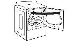
Rear Exhaust Duct
Remove the rear exhaust duct retaining screw. Pull out the exhaust duct.
Knockout
Cover Plate
Elbow 112" (3.8 cm)
O Preassemble a 4-in. (10 cm) elbow to the next 4-in. (10 cm) duct section. and secure all joints with duct tape. Be sure that the male end of the elbow faces AWAY from the dryer. Insert the elbow/duct assembly through the side opening and press it onto the adapter duct. Secure in place with duct tape. Be sure that the male end of the duct protrudes 1. in. (3.8 cm) to connect the remaining ductwork. Attach cover plate to the back of the dryer with included screw.
Your new dryer is shipped to vent to the rear. It can also be configured to vent to the bottom or side (right-side venting is not available on gas models).
Option 2 : Bottom venting
Rear Exhaust Duct
Retaining Screw
Remove the rear exhaust duct retaining screw. Pull out the exhaust duct.
Knockout
Cover Plate
Elbow
O Insert the 4-in. (10 cm) elbow through the rear opening and press it onto the adapter duct. Be sure that the male end of the elbow faces down through hole in the bottom of the dryer. Secure in place with duct tape. Attach the cover plate to the back of the dryer with included screw.
One-Year Limited Warranty
When installed. operated and maintained according to all instructions supplied with the product. if this appliance fails due to a defect in material and workmanship within one year from the date of purchase.
If this appliance is ever used for other than private family purposes. this warranty applies for only 90 days from the date of purchase.
This warranty covers only defects in material and workmanship.
Expendable items that can wear out from normal use. including but not limited to filters. belts. light bulbs. and bags.
A service technician to instruct the user in correct product installation. operation or maintenance.
A service technician to clean or maintain this product.
Damage to or failure of this product if it is not installed. operated or maintained according to all the instruc tions supplied with the product.
Damage to or failure of this product resulting from accident. abuse. misuse or use for other than its intend ed purpose.
Damage to or failure of this product caused by the use of detergents. cleaners. chemicals or utensils other than those recommended in all instructions supplied with the product.
Damage to or failure of parts or systems resulting from unauthorized modifications made to this product.
Disclaimer of implied warranties; limitation of remedies
Customer s sole and exclusive remedy under this limited warranty shall be product repair as provided herein.
Implied warranties. including warranties of merchantability or fitness for a particular purpose. are limited to one year or the shortest period allowed by law. Sears shall not be liable for incidental or consequential damages.
Some states and provinces do not allow the exclusion or limitation of incidental or consequential damages. or limitation on the duration of implied warranties of merchantability or fitness. so these exclusions or limitations may not apply to you.
This warranty applies only while this appliance is used in the United States or Canada.
This warranty gives you specific legal rights. and you may also have other rights which vary from state to state.
Sears Brands Management Corporation.