ge.com
[:3
--0
¢-
¢-
°.1-!
[:3
Safety Instructions .......... 2-5
Operating Instructions
Bridge Burner ....................... 8
Cooktop Vent System .............. 8
Cookware Tips ...................... 9
Dual Surface Unit ................... 8
Features of Your Cooktop ........... 6
Surface Units ..................... 7, 8
Temperature Limiter ................ 8
Care and Cleaning
Control Knobs ..................... 10
Glass Cooktop ................. 11, 12
Vent Filter and Chamber .......... 10
Vent Sgstem ...................... 10
Installation Instructions
Ductwork .................. 17-20, 24
Electrical Connections ......... 24-26
Exhaust Blower Ratings ........... 19
Final Assemblg .................... 27
Installing the Cooktop ......... 22-2/4
Installing the Gasket ............... 21
Preparation .................... 15-17
Safetg Precautions ................ 13
Unpacking the Cooktop ....... 1/4,21
Troubleshooting Tips ......... 28
Consumer Support
Consumer Support ................ 32
Product Registration ........... 29, 30
Warranty .......................... 31
Write the model and serial
numbers here:
Model #
Serial #
Find these numbers on o Iobel
under the cooktop, on the side
of the vent chomber.
PP989
49-80517-1 09-08 JR
IMPORTANTSAFETYINFORMATION.
READALL INSTRUCTIONS BEFOREUSING.
SAFETY PRECAUTIONS
,_ WARNING- ToREOUCETHERISK
OF FIRE,ELECTRICSHOCKOR INJURYTO
PERSONS,OBSERVETHEFOLLOWING:
A. Usethis unit onl U in the manner intended
bUthe manufacturer. If Uou have questions,
contact the manufacturer.
B°
C°
D.
Before servicing or cleaning unit, switch power
off at service panel and lock the service
disconnecting means to prevent power from
being switched on accidentall U.When the
service disconnecting means cannot be locked,
securelUfasten a prominent warning device,
such as a tag, to the service panel.
Do not use this unit with anU solid-state speed
control device.
This unit must be grounded.
€_.AUTION- Forgeneralventilating
use only. Do not use to exhaust hazardous or
explosive materials and vapors.
WARNING- ToREOUCETHERISK
OF INJURYTO PERSONSIN THEEVENTOFA
COOKTOPGREASEFIRE,OBSERVETHE
FOLLOWING*:
A. SMOTHER FLAMES with a close-fitting lid, cookie
sheet or metal tray, then turn off the burner.
BECAREFULTO PREVENTBURNS.If the flames
do not go out immediately, EVACUATEAND
CALLTHEFIREDEPARTMENT.
B. NEVER PICKUPA FLAMING PAN-
You may be burned.
C DO NOT USE WATER,includingwet
dishclothsortowels-aviolentsteam
explosion will result.
D. Usean extinguisher ONLYif:
1. You know you have a Class ABC
extinguisher, and you already know
how to operate it.
2. The fire is small and contained in the
area where it started.
3. The fire department is being called.
4. You can fight the fire with your back
to an exit.
* Based on "Kitchen FiresafetLjTips" published
by NFPA.
WARNING - m REOUCETHERISK
OF A COOKTOPGREASEFIRE:
A. Never leave surface units unattended at high
settings. Boiloverscause smoking and greasy
spillovers that may ignite. Heat oils slowly on
low or medium settings.
B. Always turn hood ON when cooking on high
heat or when flambeing food (i.e.Crepes
Suzette,Cherries Jubilee, Peppercorn Beef
Flambe).
C. Clean ventilating funs frequently. Grease should
not be allowed to accumulate on fan or filter.
D. Use proper pan size.Always use cookware
appropriate for the size of the surface element.
WARNING - ToREOUCETHERISK
OF FIRE,ELECTRICSHOCKOR INJURY TO
PERSONS,OBSERVETHEFOLLOWING:
A. Installation work and electrical wiring must
be done by qualified person(s)in accordance
with all applicable codes and standards,
including fire-rated construction.
B. Sufficient air is needed for proper combustion
and exhausting of gases through the flue
(chimney) of fuel burning equipment to prevent
back drafting. Follow the heating equipment
manufacturer's guideline and safety standards
such as those published by the National Fire
Protection Association (NFPA),and the American
Society for Heating, Refrigeration and Air
Conditioning Engineers (ASHRAE),and the local
code authorities.
C. When cutting or drilling into wall or ceiling,do
not damage electrical wiring and other hidden
utilities.
D. Ducted fans must always be vented to the
outdoors.
,_ WARNING - ToREOUCETHERISK
OF FIRE,USEONLYMETALDUCTWORK.
Do not attempt to repair or replace any
part of your downdraft cooktop unless it is
specifically recommended in this manual.
All other servicing should be referred to a
qualified technician.
ge.COl_
WARNING!
For your safety, the information in this manual must be followed to minimize the risk of fire or
explosion, electric shock, or to prevent property damage, personal injury, or loss of life.
SAFETY PRECAUTIONS
When using electrical appliances, basic safety precautions should be followed, including
the following:
Be sure your appliance is properly installed
and grounded by a qualified technician
in accordance with local codes and the
provided installation instructions.
Have the installer show you the location
of the circuit breaker or fuse. Mark it for
easy reference.
Do not leave children aloneichildren should
not be left alone or unattended in an area
where an appliance is in use. They should
never be allowed to sit or stand on any part
of the appliance.
Teach children not to play with the controls
or any other part of the cooktop.
Do not allow anyone to climb, stand or hang
on the cooktop.
CAUTION:Items of interest to
children should not be stored in cabinets
above a cooktopichildren climbing on the
cooktop to reach items could be seriously
injured.
Always keep combustible wall coverings,
curtains or drapes a safe distance from
your cooktop.
Always keep dish towels, dishcloths, pot
holders and other linens a safe distance
away from your cooktop.
Always keep wooden and plastic utensils
and canned food a safe distance away from
your cooktop.
Never wear loose-fitting or hanging
garments while using the appliance.
Flammable material could be ignited if
brought in contact with hot surface units
and may cause severe burns.
Use only dry pot holders-moist or damp
pot holders on hot surfaces may result in
burns from steam. Do not let pot holders
touch hot surface units. Do not use a towel
or other bulky cloth. Such cloths can catch
fire on a hot surface unit.
Foryour safety, never use your appliance
for warming or heating the room.
Do not use water on grease fires. Never
pick up a flaming pan. Turn the controls
off. Smother a flaming pan on a surface
unit by covering the pan completely with
well-fitting lid, cookie sheet or flat tray.
Use a multi-purpose dry chemical or foam-
type extinguisher.
Flaming grease outside a pan can be
put out by covering with baking soda or,
if available, by using a multi-purpose dry
chemical or foam-type fire extinguisher.
COOK MEATAND POULTRY THOROUGHLY...
Cook meat and poultry thoroughly-meat to at least on INTERNAL temperature of 160°F and
poultry to at least on INTERNAL temperature of l 80°F. Cooking to these temperatures usually
protects against foodborne illness.
3
IMPORTANTSAFETYINFORMATION.
READALL INSTRUCTIONS BEFOREUSING.
,ik WARNING!
PRECAUTIONS
iiiiiiiliiii!
iiiiiiiliiii!
iiiiiiiliiii!
iiiiiiiliiii!
iiiiiiiiiiii!
iiiiiiiliiii!
iiiiiiiliiii!
iiiiiiiliiii!
iiiiiiiliiii!
Do not let cooking grease or other
flammable materials accumulate on
the cooktop.
Do not touch surface units. These surfaces
may be hot enough to burn even though
they are dark in color. During and after use,
do not touch, or let clothing or other
flammable materials contact the surface
units or areas nearby the surface units; allow
sufficient time for cooling first.
Potentially hot surfaces include the cooktop
and areas facing the cooktop.
To minimize the possibility of burns, ignition
of flammable materials and spillage, the
handle of a container should be turned
toward the center of the cooktop without
extending over any nearby surface units.
Always turn the surface unit control to off
before removing the cookware.
Use little fat for effective shallow or deep-fat
frying. Filling the pan too full of fat can cause
spillovers when food is added.
If a combination of oils or fats will be used
in frying, stir together before heating, or as
fats melt slowly.
Always heat fat slowly and watch as it heats.
Use a deep fat thermometer whenever
possible to prevent overheating fat beyond
the smoking point.
Never try to move a pan of hot fat,
especially a deep fat fryer. Wait until the
fat is cool.
Do not store flammable materials near
the cooktop.
Keep the vent grille and grease filters clean
to maintain good venting and to avoid
grease fires.
Use proper pan sizeJSelect cookware
having flat bottoms large enough to cover
the surface unit heating element. The use
of undersized cookware will expose a portion
of the surface unit to direct contact and
may result in ignition of clothing. Proper
relationship of cookware to burner will
also improve efficiency.
Never leave surface units unattended at high
heat settings. Boilovers cause smoking and
greasy spillovers that may catch on fire.
Only certain types of glass, glass/ceramic,
earthenware or other glazed containers are
suitable for cooktop cooking; others may
break because of the sudden change in
temperature.
Keep an eye on foods being fried at high or
medium high heat settings.
Foods for frying should be as dry as possible.
Frost on frozen foods or moisture on fresh
foods can cause hot fat to bubble up and
over the sides of the pan.
Do not store or use combustible materials,
gasoline or other flammable vapors and
liquids in the vicinity of this or any appliance.
Clean only parts listed in this Owner's
Manual.
Do not leave paper products, cooking
utensils or food on the cooktop when not
in use.
Keep cooktop clean and free of
accumulation of grease or spillovers
which may ignite.
Never heat unopened food containers.
Pressure buildup may make container
burst and cause injury.
Never leave jars or cans of fat drippings
on or near your cooktop.

ge.com
RADIANT SURFACEUNITS
Use care when touching the cooktop. The glass surface of the cooktop will retain heat after the
controls have been turned off.
Avoid scratching the glass cooktop.
The cooktop can be scratched with items
such as sharp instruments, rings or other
jewelry and rivets on clothing.
Large scratches or impacts to glass
cooktops can lead to broken or
shattered glass.
Never use the glass cooktop surface as
a cutting board.
Do not place or store items on top of the
glass cooktop surface when it is not in use.
Be careful when placing spoons or other
stirring utensils on glass cooktop surface
when it is in use. They may become hot and
could cause burns.
Avoid heating an empty pan. Doing so may
damage the cooktop and the pan.
Do not allow water, other liquids or grease
to remain on the cooktop.
To minimize the possibility of burns, always
be certain that the controls for all surface
units are at the off position and the entire
glass surface is cool before attempting to
clean the cooktop.
Do not operate the glass surface units if
the glass is broken. Spillovers or cleaning
solution may penetrate a broken cooktop
and create o risk of electrical shock. Contact
o qualified technician immediately should
your glass cooktop become broken.
iiiiiiiliiii!
iiiiiiiliiii!
iiiiiiiliiii!
iiiiiiiliiii!
iiiiiiiliiii!
iiiiiiiliiii!
Clean the cooktop with caution. If a wet
sponge or cloth is used to wipe spills on
o hot surface unit, be careful to avoid
steam burns. Some cleansers con produce
noxious fumes if applied to a hot surface.
NOTE: We recommend that you avoid
wiping any surface unit areas until they
have cooled and the indicator light has
gone off. Sugar spills are the exception to
this. Please see Cleaning the Glass Cooktop
in the Care and Cleaning section.
When the cooktop is cool, use only
CERAIVlABRYTE® Ceramic Cooktop
Cleaner and the CERAMA BRVTE®
Cleaning Pod to clean the cooktop.
To avoid possible damage to the cooking
surface, do not apply the cleaning cream
to the glass surface when it is hot.
After cleaning, use a dry cloth or paper towel
to remove all the cleaning cream residue.
Read and follow oil instructions and
warnings on the cleaning cream labels.
Use care when touching the cooktop. The
glass surface of the cooktop will retain heat
after the controls have been turned OFF.
iiiil}iiiiiDo not stand on the glass cooktop.
READAND FOLLOWTHISSAFETYINFORMATIONCAREFULLY.
SAVETHESEINSTRUCTIONS

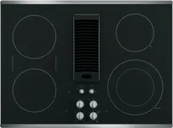
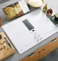
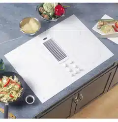
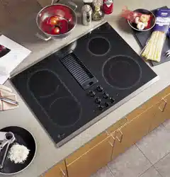
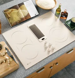
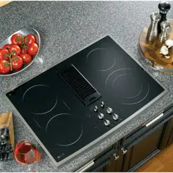
Features of Your Cooktop.
Throughout this manual, features and appearance may vary from your model.
L
Feature Index (Features and appearance mag vary)
0 Left Rear Surface Unit
Bridge Surface Unit
Left Front Surface Unit
Vent Grille
Vent Filter (below the vent grille)
Right Rear Surface Unit
Ouol Surface Unit
O Model and Serial Number Label (underthe cooktop,
on the right side of the vent chamber)
Left Rear Surface Unit Control
Left Front Surface Unit Control
CONTROL LOCK
UNLOCK
o
LOCK _
HOT
,
0 Left Side Hot Surface Indicator Lights (onefor each surface unit)
Vent Fan Speed Control
Control Lock Knob
FAN
OFF
• ®
Right Side Hot Surface Indicator Lights (oneforeachsurfaceunit)
0 0uol Surface Unit Control
Right Rear Surface Unit Control
Surface Unit On Indicator Light
Usingthe surface units. 9e.com
! iiiii) !J! ii!i i5
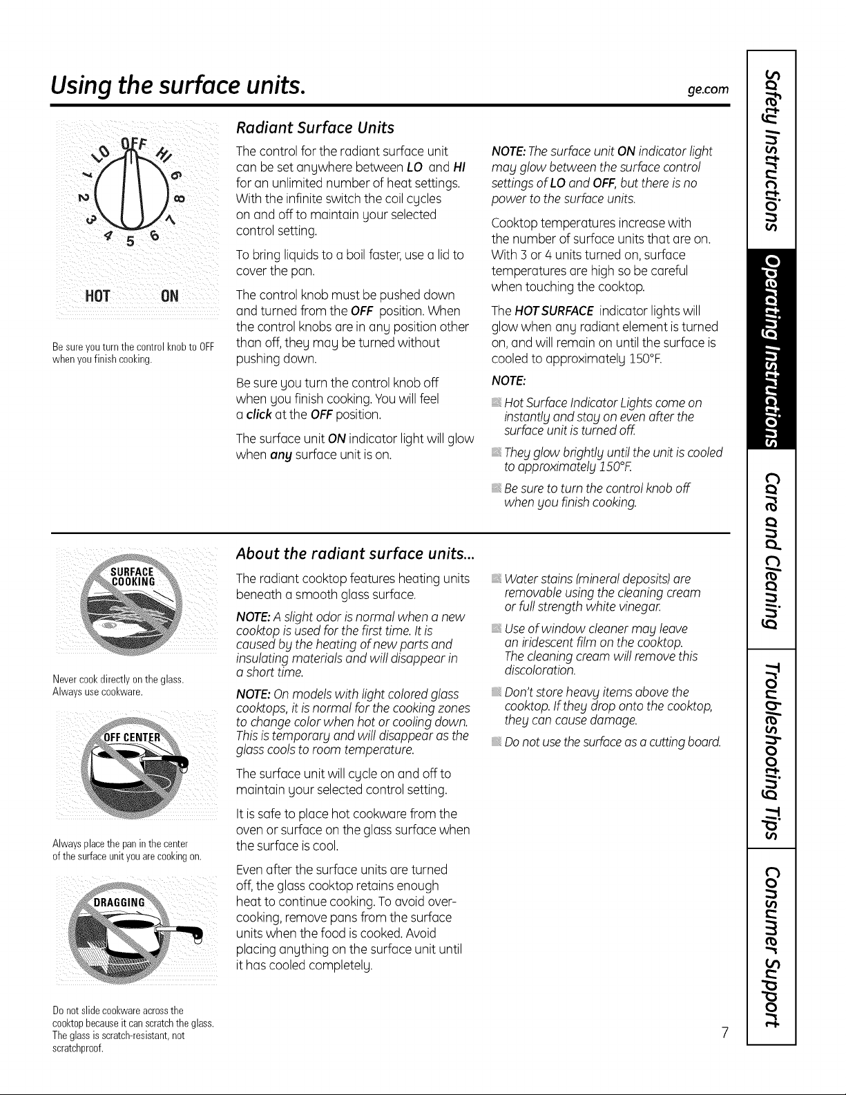
Radiant Surface Units
The control for the radiant surface unit
con be set ongwhere between LO and HI
for on unlimited number of heat settings.
With the infinite switch the coil cgcles
on and off to maintain gour selected
control setting.
To bring liquids to o boil foster, use o lid to
cover the pon.
HOT ON The control knob must be pushed down
and turned from the OFF position. When
the control knobs ore in ong position other
Besureyou turn the control knobto OFF than off,theg mog be turned without
whenyou finish cooking, pushing down.
Besure gou turn the control knob off
when gou finish cooking. Youwill feel
o clickat the OFFposition.
The surface unit ON indicator light will glow
when any surface unit is on.
NOTE:Thesurface unit ON indicator light
may glow between the surface control
settings of LOand OFF,but there is no
power to the surface units.
Cooktop temperatures increasewith
the number of surface units that ore on.
With 3 or 4 units turned on, surface
temperatures ore high so be careful
when touching the cooktop.
The HOTSURFACEindicator lights will
glow when ang radiant element is turned
on, and will remain on until the surface is
cooled to opproximotelg 150°R
NOTE:
HotSurface Indicator Lights come on
instantly and stay on even after the
surface unit is turned off.
The_lglow brightl_luntil the unit is cooled
to opproximotel_1150°K
Besure to turn the control knob off
when you finish cooking.
i ¸¸ cE_
i¸¸................!
Nevercookdirectly onthe glass.
Alwaysuse cookware.
Alwaysplacethe panin the center
of the surfaceunit youare cookingon.
About the radiant surface units...
The radiant cooktop features heating units
beneath o smooth gloss surface.
NOTE:A slight odor is normal when o new
cooktop is used for the first time. It is
causedby the heating of new parts and
insulating materials and will disappear in
o short time.
NOTE:Onmodels with light colored glass
cooktops, it is normal for the cooking zones
to change color when hot or cooling down.
Thisis temporary and will disappear as the
glass cools to room temperature.
The surface unit will cucle on and offto
maintain your selected control setting.
It is safe to place hot cookwore from the
oven or surface on the glass surface when
the surface is cool.
Evenafter the surface units ore turned
off, the gloss cooktop retains enough
heat to continue cooking. To ovoid over-
cooking, remove pans from the surface
units when the food is cooked. Avoid
placing anything on the surface unit until
it has cooled completely.
iiiilDiiii
Water stains (mineraldeposits)are
removableusing the cleaning cream
or full strength white vinegar,
Useof window cleanerma_l leave
an iridescent film on the cooktop.
Thecleaning cream will remove this
discoloration.
Don't store heav_litems above the
cooktop.If they drop onto the cooktop,
they con causedamage.
Do not use thesurfaceas a cutting board.
Do not slidecookwareacrossthe
cooktopbecauseit canscratchthe glass.
The glassis scratch-resistant,not
scratchproof.
Usingthe surface units.
i :U[)_F: ¸
ii¸(L i_ _
ii {o__//I I _€ L¸
ii! ¸¸¸¸¸¸¸¸¸¸¸-4__:
iii/_ 4/
i [i:i:i !!i/i:
LO L£b_
s a,i
surfaceunit Large9"
setting surfaceunitsetting
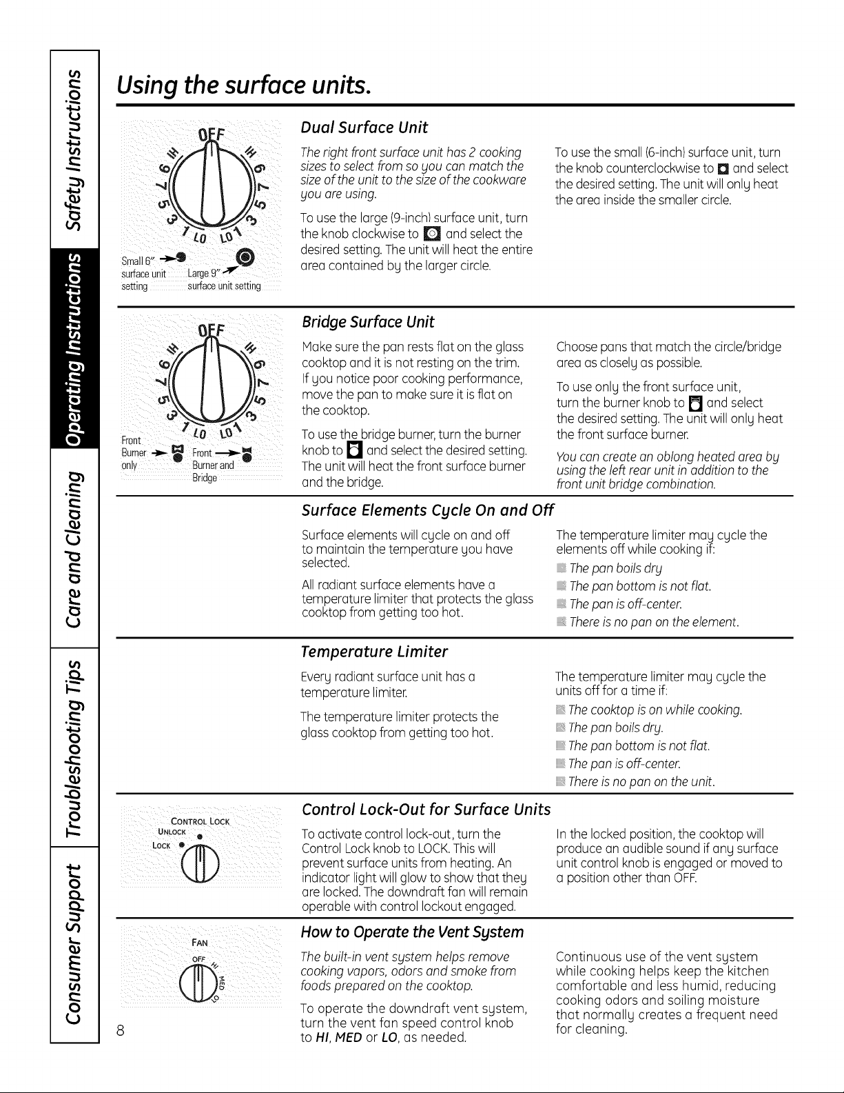
Dual Surface Unit
The right front surface unit has 2 cooking
sizes to select from so you can match the
size of the unit to the size of the cookware
you are using.
To use the large (9-inch/surface unit, turn
the knob clockwise to I[_ and select the
desired setting.The unit will heat the entire
area contained by the larger circle.
To use the small (6-inch)surface unit, turn
the knob counterclockwise to rl and select
the desired setting.The unit will only heat
the area insidethe smaller circle.
Front LO
Burnei _ Front----_
only Burnerand
Bridge
Bridge Surface Unit
Moke suretheponrestsfloton thegloss
cooktopond itisnotrestingon thetrim.
Ifyou noticepoorcookingperformonce,
move thepontomoke sureitisfloton
thecooktop.
To usethebridgeburner,turntheburner
knobtoPI ondselectthedesiredsetting.
Theunitwillheotthefrontsurfoceburner
ondthebridge.
Choosepans that match the circle/bridge
area as closely as possible.
To use only the front surface unit,
turn the burner knob to [] and select
the desired setting. The unit will only heat
the front surface burner.
Youcon createon oblong heated area bg
using the left rear unit in addition to the
front unit bridge combination.
Surface Elements Cycle On and Off
Surface elements will cycle on and off
to maintain the temperature you have
selected.
All radiant surface elements hove o
temperature limiter that protects the gloss
cooktop from getting too hot.
The temperature limiter may cycle the
elements off while cooking if:
Thepan boils dry
Thepan bottom is not flat.
Thepan is off-center.
Thereis no pan on the element.
Temperature Limiter
Every radiant surface unit has o
temperature limiter.
The temperature limiter protects the
glasscooktop from getting too hot.
The temperature limiter may cycle the
units offfor a time if:
Thecooktop is on while cooking.
Thepan boils dry.
Thepan bottom is not flat.
Thepan is off-center.
Thereis no pan on the unit.
Control Lock-Out for Surface Units
UNLOCK
LOCK• .,_
@
OFF 4,/
To activate control lock-out, turn the
Control Lockknob to LOCK.Thiswill
prevent surface units from heating. An
indicator light will glow to show that they
are locked.The downdraft fan will remain
operable with control lockout engaged.
How to Operate the Vent System
Thebuilt-in vent %Istem helps remove
cooking vapors, odors and smoke from
foods prepared on the cooktop.
To operate the downdraft vent system,
turn the vent fan speed control knob
to HI, MED or LO, as needed.
In the locked position, the cooktop will
produce on audible sound if any surface
unit control knob is engaged or moved to
o position other than OFE
Continuous use of the vent system
while cooking helps keep the kitchen
comfortable and less humid, reducing
cooking odors and soiling moisture
that normally creates a frequent need
for cleaning.
Selectingtypesof cookware, ge.com
The following information will help you choose cookware which will give good performance on glass cooktops.
Use a pan that matches the diameter of the surface element you are using. Cooking performance will not be as
good if the cookware itself is smaller or larger than the surface unit.
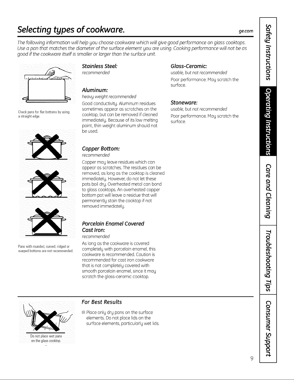
Checkpansfor flat bottomsby using
a straight edge.
Stainless Steel:
recommended
Aluminum:
heavy weight recommended
Goodconductivity. Aluminum residues
sometimes appear as scratches on the
cooktop, but can be removed if cleaned
immediately. Because of its low melting
point, thin weight aluminum should not
be used.
Glass-Ceramic:
usable,but not recommended
Poorperformance. May scratch the
surface.
Stoneware:
usable,but not recommended
Poorperformance. May scratch the
surface.
Copper Bottom:
recommended
Copper may leave residueswhich can
appear as scratches.The residuescan be
removed, as long as the cooktop is cleaned
immediately. However,do not let these
pots boil dry. Overheated metal can bond
to glass cooktops. An overheated copper
bottom pot will leave a residuethat will
permanently stain the cooktop if not
removed immediately.
Panswith rounded,curved,ridgedor
warped bottomsare not recommended.
Porcelain Enamel Covered
Cast Iron:
recommended
As long as the cookware is covered
completely with porcelain enamel, this
cookware is recommended. Caution is
recommended for cast iron cookware
that is not completely covered with
smooth porcelain enamel, since itmay
scratch the glass-ceramic cooktop.
Do not place wet pans
on theglass Cooktop.
For Best Results
Placeonly dry pans on the surface
elements. Do not place lids on the
surface elements, particularly wet lids.
9
Careand cleaning of the cooktop.
Be sure electrical power is off and all surfaces are cool before cleaning any part of the cooktop.
How to Remove Protective Shipping Film and Packaging Tape
Carefully grasp a corner of the protective
shipping film with gour fingers and slowlg
peel it from the appliance surface. Do not
use ang sharp items to remove the film.
Removeall of the film before using the
appliance for the first time.
To assure no damage is done to the finish
of the product, the safest wag to remove
the adhesive from packaging tape on new
appliances is an application of a household
liquid dishwashing detergent. Applg with a
soft cloth and allow to soak.
NOTE:Theadhesive must be removed
from all parts. It cannot be removed if it is
baked on.
Vent Grille
Before cleaning the vent grille, be sure
the exhaust blower is turned off.
To clean the vent grille, remove it from
the cooktop by lifting it up and off.
Wipe with a damp clotH. If necessarg,
the vent grille can be washed in the sink.
Usedishwashing liquidfor cleaning.
Do not use abrasive cleaners. Theg will
damage the vent grille'sfinish.
Do not clean the vent grille in the
dishwasher.
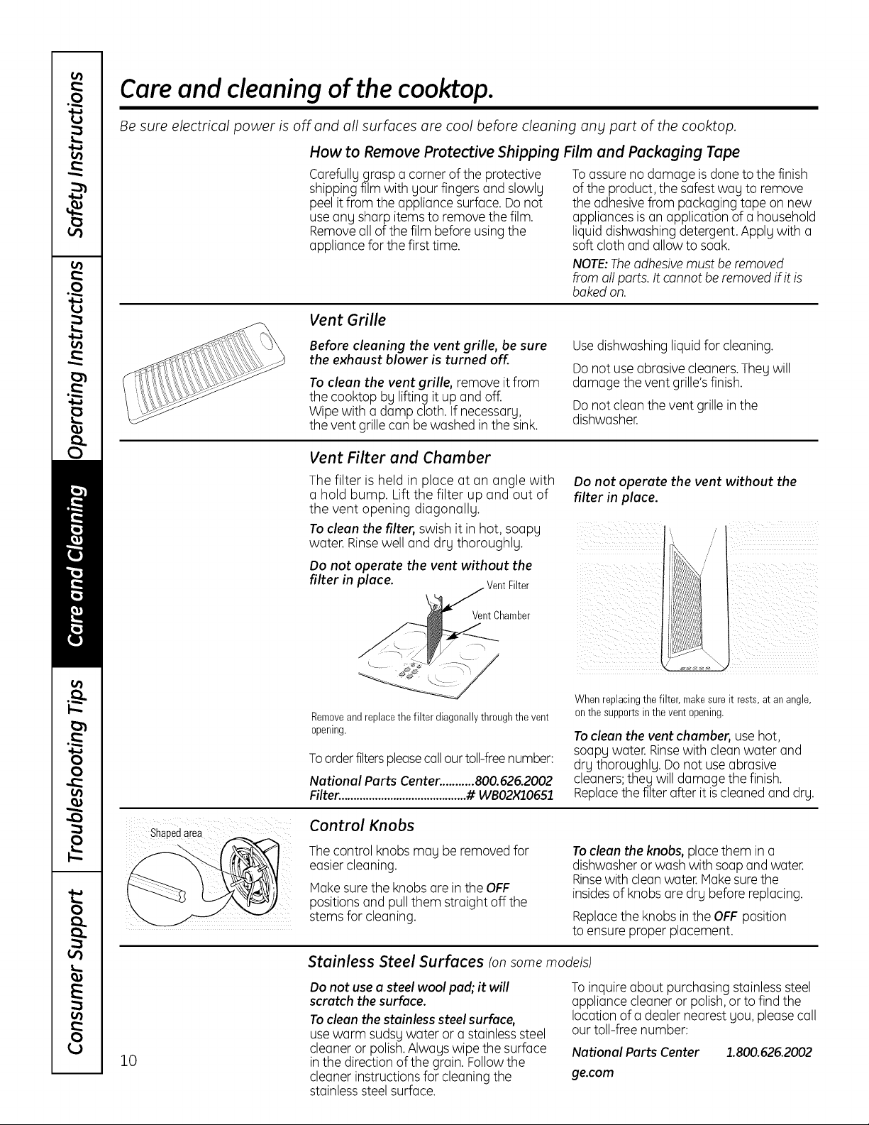
Vent Filter and Chamber
The filter is held in place at an angle with
a hold bump. Lift the filter up and out of filter in place.
the vent opening diagonallg.
To clean the filter, swish it in hot, soapg
water. Rinse well and drg thoroughlg.
Do not operate the vent without the
Do not operate the vent without the
filter in place.
Vent Chamber
Removeand replacethe filter diagonallythroughthe vent
opening.
To order filters please call our toll-free number:
National Parts Center. ..........800.626.2002
Filter. .........................................# WBO2X10651
When replacingthe filter, makesure it rests, at an angle,
on the supportsin the vent opening.
To clean the vent chamber, use hot,
soapg water. Rinsewith clean water and
drg thoroughlg. Do not use abrasive
cleaners;theg will damage the finish.
Replacethe filter after it is cleaned and drg.
ShaPedarea Control Knobs
The control knobs mag be removed for
easier cleaning.
Make sure the knobs are in the OFF
positions and pull them straight off the
stems for cleaning.
To clean the knobs, place them in a
dishwasher or wash with soap and water.
Rinsewith clean water. Hakesure the
insidesof knobs are drg before replacing.
Replacethe knobs inthe OFF position
to ensure proper placement.
10
Stainless Steel Surfaces (onsomemodels)
Do not use a steel wool pad; it will
scratch the surface.
To clean the stainless steel surface,
use warm sudsg water or a stainless steel
cleaner or polish.Alwags wipe the surface
in the direction of the grain. Followthe
cleaner instructions for cleaning the
stainlesssteel surface.
To inquire about purchasing stainless steel
appliance cleaner or polish, or to find the
location of a dealer nearest gou, please call
our toll-free number:
National Parts Center 1.800.626.2002
ge.com
Cleaning the glass cooktop, ge.com
Clean yourcooktopalter
each spill. Use CERAMA
BRYTE® CeramicCooktop
Cleaner.
Normal Daily Use Cleaning
ONLYuse CERAMABRYTE®Ceramic
Cooktop Cleaner on the glass cooktop.
Other creams may not be as effective.
To maintain and protect the surface of
your glass cooktop, follow these steps:
[]
Before using the cooktop for the
first time, clean it with CERAMA
BRYTE®Ceramic Cooktop Cleaner.
Thishelps protect the top and makes
clean-up easier.
[_ Daily use of CERAHABRYTE®Ceramic
Cooktop Cleaner will help keep the
cooktop looking new.
%
Shakethe cleaning cream well,
Apply a few drops of CERAMA
BRYTE®Ceramic Cooktop Cleaner
directly to the cooktop.
Usea paper towel or CERAMA
BRYTE®Cleaning Padfor Ceramic
Cooktopsto clean the entire cooktop
surface.
J_ Use a dry cloth or paper towel
to remove all cleaning residue.
No need to rinse.
NOTE: It is very important that you DO
NOTheat the cooktop until it has been
cleaned thoroughly.
Usea CERAMABRYTE® CleaningPad
for CeramicCooktopsor a Scotch-Brite®
Multi-PurposeNo Scratchbluescrub
pad.
Burned-On Residue
WARNING: DAMAGEto
your glass surface may occur if Fou use
scrub pads other than the pod included
with your cooktop.
[_ Allow the cooktop to cool.
[_ Spread a few drops of CERAMA
BRYTE®Ceramic Cooktop Cleaner
to the entire burned residue area.
%
Using the included CERAMABRYTE®
Cleaning Pad for Ceramic Cooktops,
rub the residue area, applying
pressure as needed.
[]
%
If any residue remains, repeat the
steps listed above as needed.
For additional protection, after all
residue has been removed, polish
the entire surface with CERAMA
BRYTE®Ceramic Cooktop Cleaner
and a paper towel.
The CERAMABRYTE® CeramicCooktop
Scraperand all recommendedsupplies
are availablethroughour PartsCenter.
Seeinstructionsunder"To OrderParts"
sectionon nextpage.
NOTE:Do not usea dull ornicked
blade.
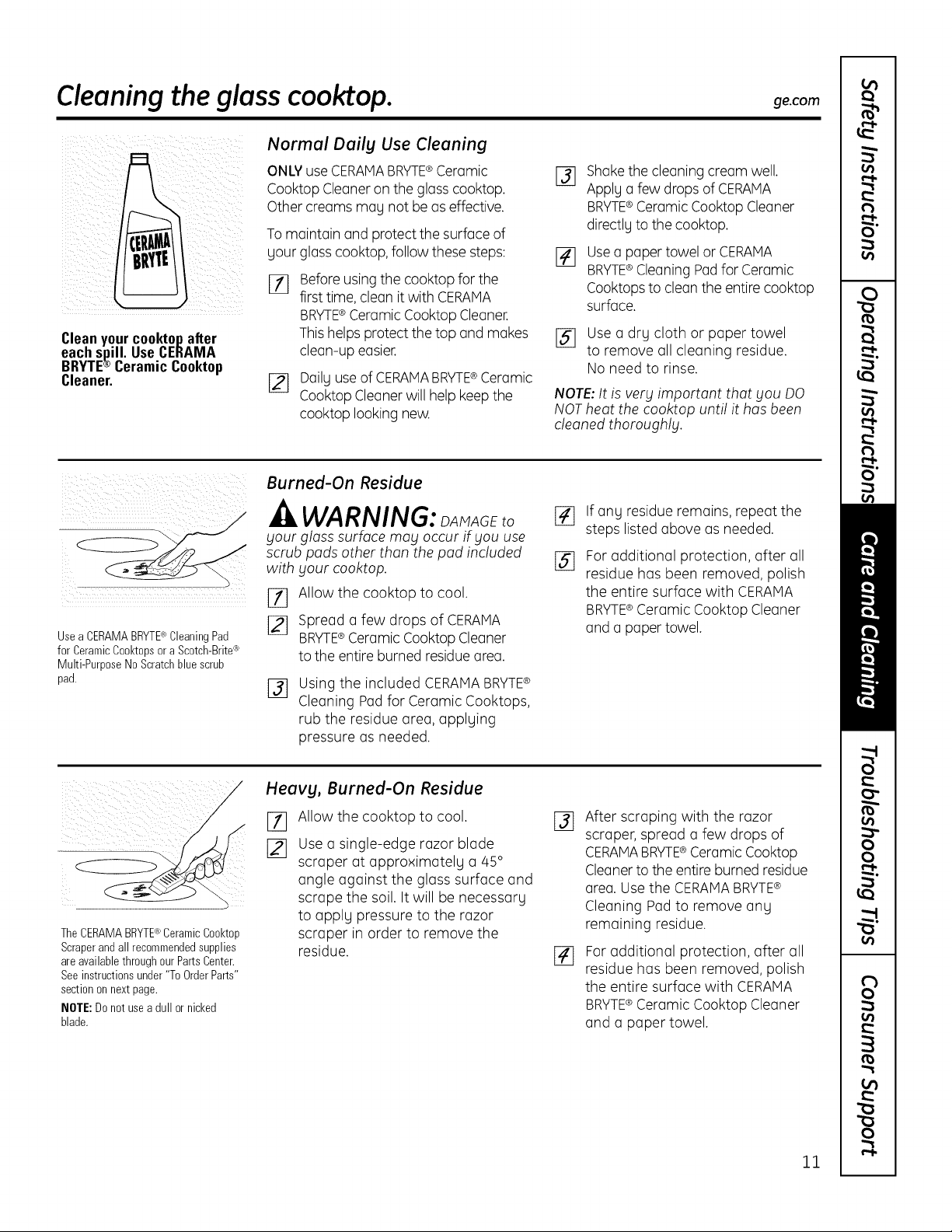
Heavg, Burned-On Residue
%
[]
Allow the cooktop to cool.
Use a single-edge razor blade
scraper at approximately a 45 °
angle against the glass surface and
scrape the soil. It will be necessary
to apply pressure to the razor
scraper in order to remove the
residue.
%
[]
After scraping with the razor
scraper, spread a few drops of
CERAMABRYTE® Ceramic Cooktop
Cleanerto the entire burned residue
area. Use the CERAMABRYTE®
Cleaning Pad to remove any
remaining residue.
For additional protection, after all
residue has been removed, polish
the entire surface with CERAMA
BRYTE®Ceramic Cooktop Cleaner
and a paper towel.
ll
Cleaning the glass cooktop.
Metal Marks and Scratches
%
Be careful not to slide pots and
pans across gour cooktop. It will
leave metal markings on the
cooktop surface.
These marks are removable using
the CERAMABRYTE®Ceramic
Cooktop Cleaner with the
CERAMABRYTE®Cleaning Pad
for Ceramic Cooktops.
[_ If pots with a thin overlay of
aluminum or copper are allowed
to boil drg, the overlag mag leave
black discoloration on the cooktop.
This should be removed
immediatelg before heating again
or the discoloration mag be
permanent.
WARNING: Corefully
check the bottom of pans for roughness
that would scratch the cooktop.
Glasssurface--potential for permanent damage.
Ourtestingshows that
if youare cookinghigh
sugar mixturessuch as
jelly or fudge andhave
a spillover,it can cause
permanentdamageto the
glasssurface unlessthe
spillover is immediately
removed.
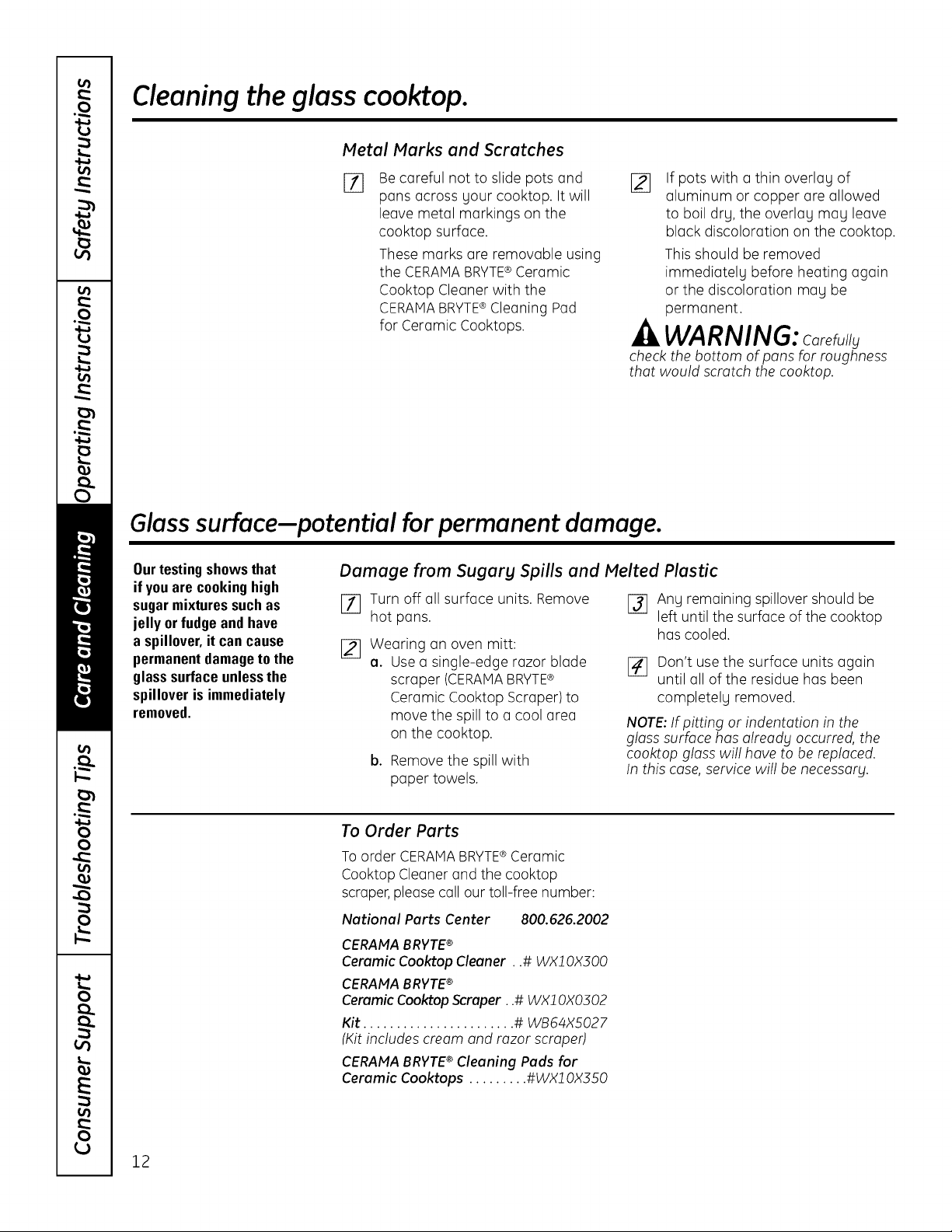
Damage from Sugary Spills and Melted Plastic
[] Turn off all surface units. Remove
hot pans.
[]
Wearing an oven mitt:
o. Usea single-edge razor blade
scraper (CERAMABRYTE®
Ceramic Cooktop Scraper) to
move the spill to a cool area
on the cooktop.
b. Remove the spill with
paper towels.
r_ Ang remaining spillover should be
left until the surface of the cooktop
hascooled.
[] Don't use the surface units again
until all of the residue has been
completelg removed.
NOTE: If pitting or indentation in the
gloss surface has olreodg occurred, the
cooktop gloss will hove to be replaced.
In this case, service will be necessorg.
To Order Parts
To order CERAMABRYTE®Ceramic
Cooktop Cleaner and the cooktop
scraper,please call our toll-free number:
National Parts Center 800.626.2002
CERAMA BRVTE®
Ceramic Cooktop Cleaner, ,# WX10X300
CERAMA BRVTE®
Ceramic Cooktop Scraper, ,# WX10X0302
Kit ....................... # WB64X5027
(Kit includes cream and razor scraper)
CERAMA BRVTE® Cleaning Pads for
Ceramic Cooktops ......... #WX10X350
12
llnstallation I Radiant
nstructlons Downdraft Cooktop
If you hove questions, call 800.GE.CARES (800.432.2737) or visit our Website at: ge.com
I
BEFORE YOU BEGIN
Read these instructions completely and
carefully.
•IMPORTANT - Savetheseinstructions
for local inspector's use.
•IMPORTANT - Observeallgoverning
codes and ordinances.
• Note to Installer- Be sure to leavethese
instructionswith the Consumer.
• Note to Consumer - Keep these instructionsfor
future reference.
• Unless verg knowledgeable in the installation of
this product, engage o professional installer.
• Proper installation is the responsibilitg of the
installer.
• Product failure due to improper installation is not
covered under the Worrontg.
-&WARNING - Beforebeginningthe
installation,switchpower offat the service
panel and lockthe servicedisconnectingmeans
to prevent power from being switchedon
accidentallg.When the servicedisconnecting
means cannot be locked,securelyfasteno
prominent warning device,such as o tog,to
the servicepanel.
IMPORTANT SAFETY INSTRUCTIONS
-_ WARNING - TO REDUCE THE RISK
OF FIRE, ELECTRIC SHOCK OR INJURY TO
PERSONS, OBSERVE THE FOLLOWING:
[] Installation work and electrical wiring must be
done bg qualified person(s)in accordance with
all applicable codes and standards, including
fire-rated construction.
r_
E]
Sufficient air is needed for proper combustion
and exhausting of gases through the flue
(chimneLl) of fuel burning equipment to
prevent back drafting. Follow the heating
equipment manufacturer's guidelines and
safetg standards such as those published %1
the National Fire Protection Association (NFPA),
and the American SocietLl for Heating,
Refrigeration and Air Conditioning Engineers
(ASHRAE), and the local code authorities.
When cutting or drilling into wall or ceiling, do
not damage electrical wiring and other hidden
utilities.
r_l Ducted fans must alwags be vented to the
outdoors.
° This unit must be properly grounded.
_4LWARNING - ToREDUCETHERISKOF
FIRE, USE ONLY METAL DUCTWORK.
13
Installation Instructions
UNPACKING YOUR COOKTOP
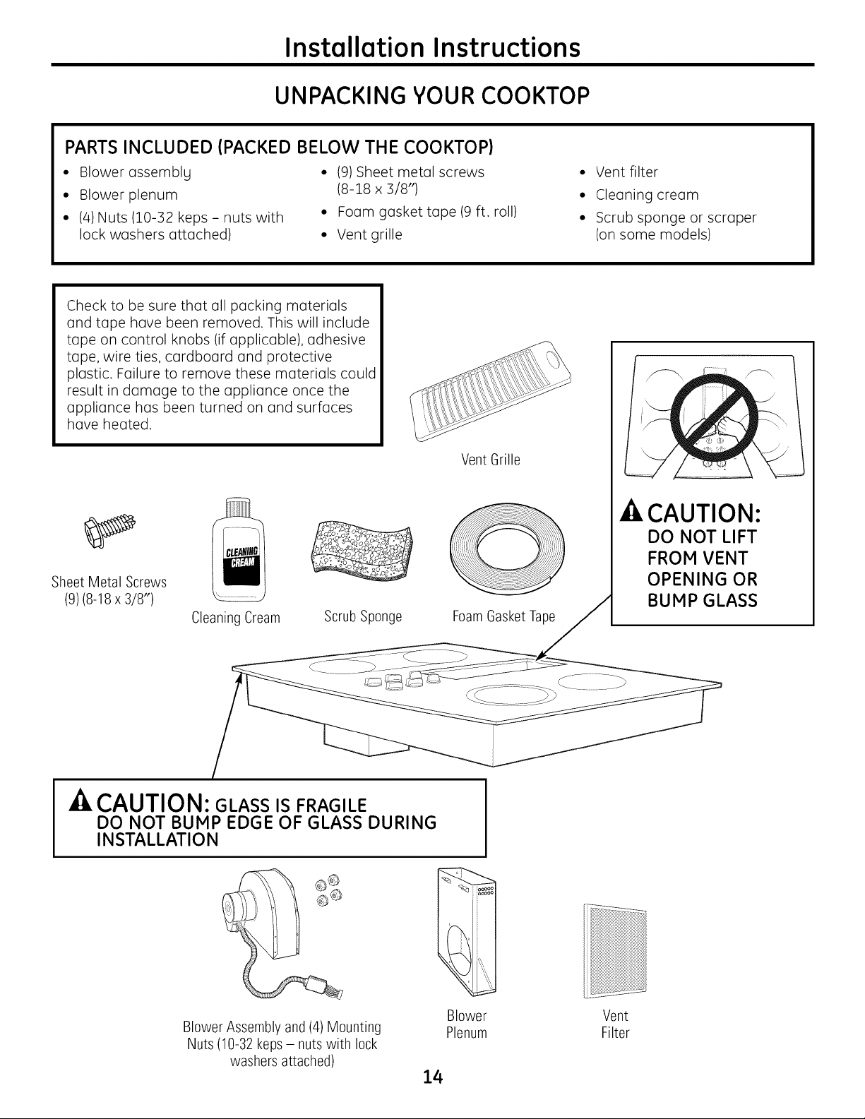
PARTS INCLUDED (PACKED BELOW THE COOKTOP)
° Blower assemblg ° (9) Sheet metal screws ° Vent filter
° Blower plenum (8-18 x 3/8") ° Cleaning cream
° (4) Nuts (10-32 keps - nuts with ° Foam gasket tape (9 ft. roll) ° Scrub sponge or scraper
lock washers attached) ° Vent grille (on some models)
Check to be sure that all packing materials
and tape have been removed. This will include
tape on control knobs (if applicable), adhesive
tape, wire ties, cardboard and protective
plastic. Failure to remove these materials could
result in damage to the appliance once the
appliance has been turned on and surfaces
have heated.
Sheet Metal Screws
(9)(8-18 x 3/8")
Cleaning Cream
Scrub Sponge
Vent Grille
/
FoamGasket Tape
CAUTION:
DO NOT LIFT
FROM VENT
OPENING OR
BUMP GLASS
-& CAUTION: GLASS IS FRAGILE
DO NOT BUMP EDGE OF GLASS DURING
INSTALLATION
Blower Assembly and (4) Mounting
Nuts (10-32 keps - nuts with lock
washers attached)
Blower Vent
Plenum Filter
14
Installation Instructions
PREPARATION
TOOLS AND MATERIALS
YOU WILL NEED
• Saw
• Flat-blade screwdriver
• Electrician's pliers
• Duct tape
• Measuring tape or scale
• Carpenter's square
• 7/16" wrench or socket set
• Drill and drill bit
• Sheet metal screws
• Junction box*
• 3/4"flexible conduit*
• Electrical wire per local code*
• Wire nuts*
• Ductwork
• NOTE: Electrical installation kit JXCK89 mag be
ordered separatelg and includes all the parts
necessarg to connect the cooktop to tgpical
rough-in wiring.
CAUTION: FOR PERSONAL SAFETY,
REMOVE HOUSE FUSE OR CIRCUIT BREAKER
BEFORE BEGINNING INSTALLATION.
ELECTRICAL REQUIREMENTS
Thisappliance must be supplied with the proper voltage
and frequency, as listedinthese Installation Instructions,
and connected to an individual, properly grounded branch
circuit, protected by a 40-amp circuit breaker or time
delay fuses.
Allwire connections must be made in accordance with
local codes and properly insulated. Checkwith your local
utility for governing electrical codes and ordinances. In the
absence of local electrical codes,the National Electrical
Code,ANSI/NFPANo. 70 - Latest Edition,governing electric
range installations,must befollowed.
A copy of the National ElectricalCodecan beobtained by
writing to:
National FireProtection Association
Batterymarch Park
Quincy, HA 02260
EffectiveJanuary 1, 1996,the National ElectricalCode
requires that new, but not existing,construction utilize a
four-conductor connection to an electric range. When
installing an electric range in new construction, follow the
instructions in NEWCONSTRUCTIONAND FOUR-
CONDUCTORBRANCHCIRCUITCONNECTION.
Youmust use a three-wire, single-phaseAC 208Y/120Volt
or 240/120 Volt, 60 Hertz electrical system with separate
ground. If you connect to aluminum wiring, properly
installed connectors approved for use with aluminum
wiring must be used.
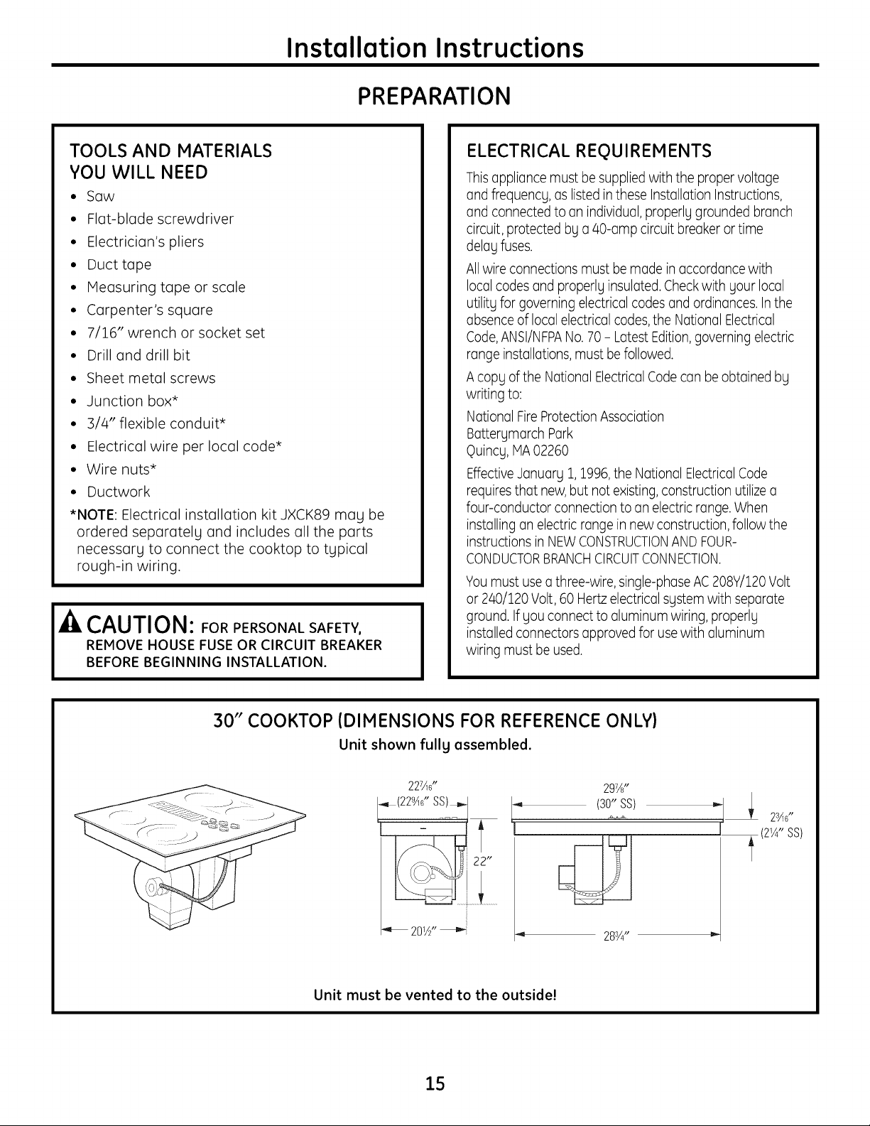
30" COOKTOP (DIMENSIONS FOR REFERENCE ONLY)
Unit shown fullg assembled.
227Ad'
_(22gAd ' SS)_,-
.,_ 283A,,
Unit must be vented to the outside!
15
Installation Instructions
CABINET PREPARATION
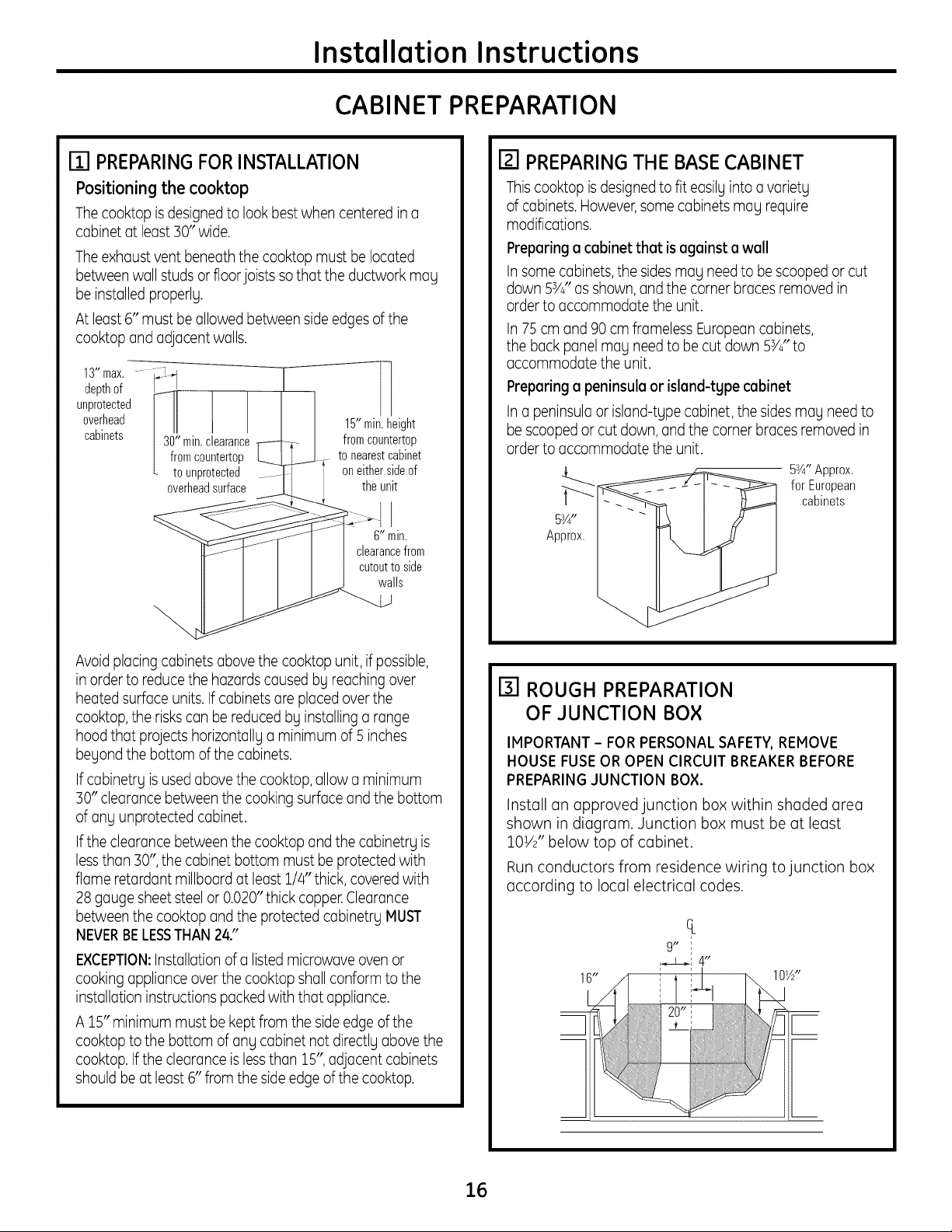
ITI PREPARINGFOR INSTALLATION
Positioning the cooktop
The cooktop is designedto look best when centered in a
cabinet at least 30" wide.
The exhaust vent beneath the cooktop must be located
between wall studs or floor joists so that the ductwork may
be installed properly.
At least 6" must be allowed between side edges of the
cooktop and adjacent walls.
13"max. -- i_-t
depthof /"
unprotected [11
overhead 15"min.height
cabinets 130" min.clearance J fromcountertop
I from countertop ......J _ to nearestcabinet
L to unprotected ........ l oneithersideof
overheadsurface.------- _ I the unit
_J---r---"f_q I _"min.
tPJT I I I clearancefrOm
II I I I I cut°utt° side
lls
Avoid placing cabinets above the cooktop unit, if possible,
in order to reduce the hazards caused by reaching over
heated surface units. If cabinets are placed over the
cooktop, the riskscan be reduced by installing a range
hood that projects horizontally a minimum of 5 inches
beyond the bottom of the cabinets.
If cabinetry is used above the cooktop, allow a minimum
30" clearance between the cooking surface and the bottom
of any unprotected cabinet.
Ifthe clearance between the cooktop and the cabinetry is
lessthan 30", the cabinet bottom must be protected with
flame retardant millboard at least 1/4" thick, covered with
28 gauge sheet steel or 0.020" thick copper.Clearance
between the cooktop and the protected cabinetry MUST
NEVERBELESSTHAN 2&"
EXCEPTION:Installation of a listed microwave oven or
cooking appliance over the cooktop shall conform to the
installation instructions packed with that appliance.
A 15" minimum must be kept from the side edge of the
cooktop to the bottom of any cabinet not directly above the
cooktop. Ifthe clearance is less than 15", adjacent cabinets
should be at least 6" from the side edge of the cooktop.
I_1 PREPARING THE BASE CABINET
Thiscooktop is designedto fit easilyinto a variety
of cabinets. However,some cabinets may require
modifications.
Preparing a cabinet that is against a wall
In some cabinets,the sides may need to be scooped or cut
down 53/4" as shown, and the corner braces removed in
order to accommodate the unit.
In 75 cm and 90 cm frameless Europeancabinets,
the back panel may need to be cut down 53/4" to
accommodate the unit.
Preparing a peninsula or island-tgpe cabinet
In a peninsula or island-type cabinet, the sides may need to
be scoopedor cut down, and the corner braces removed in
order to accommodate the unit.
53/4"Approx.
for European
cabinets
[] ROUGH PREPARATION
OF JUNCTION BOX
IMPORTANT - FOR PERSONAL SAFETY,REMOVE
HOUSE FUSEOR OPEN CIRCUIT BREAKER BEFORE
PREPARINGJUNCTION BOX.
Install an approved junction box within shaded area
shown in diagram. Junction box must be at least
lOW' below top of cabinet.
Run conductors from residence wiring to junction box
according to local electrical codes.
16"
ct
9" I
16
Installation Instructions
CABINET PREPARATION CUTOUTS
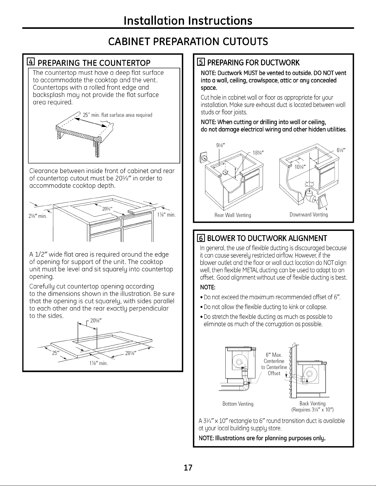
[] PREPARING THE COUNTERTOP
The countertopmust have a deep flatsurface
to accommodate the cooktop and the vent.
Countertopswith a rolledfrontedge and
backsplash may not providethe flatsurface
area required.
._t surface area required
Clearance between inside front of cabinet and rear
of countertop cutout must be 20s/a" in order to
accommodate cooktop depth.
17_"min.
A 1/2" wide flat area is required around the edge
of opening for support of the unit. The cooktop
unit must be level and sit squarely into countertop
opening.
Carefully cut countertop opening according
to the dimensions shown in the illustration. Be sure
that the opening is cut squarely, with sides parallel
to each other and the rear exactly perpendicular
to the sides.
- 20%"
17_"min.
rsi PREPARINGFORDUCTWORK
NOTE:Ductwork MUSTbe vented to outside. DO NOTvent
into a wall, ceiling, crawlspace, attic or ang concealed
space.
Cut hole in cabinet wall or floor as appropriate for gour
installation. Hake sure exhaust duct is located between wall
studs or floor joists.
NOTE:When cutting or drilling into wall or ceiling,
do not damage electrical wiring and other hidden utilities.
g_A"
1B¾"
RearWall Venting
DownwardVenting
[] BLOWERTO DUCTWORKALIGNMENT
In general,the use of flexible ducting is discouraged because
it can cause severelurestricted airflow. However,if the
blower outlet and the floor or wall duct location do NOTalign
well,then flexible METALductingcan be used to adapt to an
offset. Good alignment without use of flexible ducting is best.
NOTE:
• Do not exceed the maximum recommended offset of 6".
• Do not allow the flexible ducting to kink or collapse.
• Do stretch the flexible ducting as much as possible to
eliminate as much of the corrugation as possible.
to Centerline ZJ I Is_ LI
,,/" Offset __
BottomVenting BackVenting
(Requires3¼" x 10")
A 3Y4"x 10" rectangle to 6" round transition duct is available
at gour local building supplg store.
NOTE:lllustmtions are for planning purposes only.
17

Installation Instructions
DUCTWORK CALCULATIONS
Calculate Total Equivalent Ductwork Length
Equivalent Number Equivalent
Duct Pieces Length* x Used = Length
5" round
straight 2.7 ft. x ( ft.)_ = ft.
6" round
straight 1ft. x ( ft.)t = ft.
3V," x 10"
straight i ft. x ( ft#= ft.
5", 90°
(_ elbow 37 ft. x ( )= ft.
6", 90°
elbow 12 ft. x ( )= ft.
(_ 5"' 45°
elbow 18 ft. x ( )= ft.
6", 45°
elbow 7 ft. x ( )= ft.
Flexible
metal offset
adapter 34 ft. x ( ) = ft.
3V_" x 10"
90° elbow 14 ft. x ( )= ft.
3V_"x 10"
45° elbow 8 ft. x ( )= ft.
3V_"x i0"
90° flat elbow 33 ft. x ( )= ft.
5" round
to 3V_"x 10"
transition 3 ft. x ( )= ft.
6" round
to 3V_"x 10"
transition 2 ft. x ( )= ft.
Subtotal Column 1 = ft.
*Equivalent lengths of duct pieces are based on
actual tests and reflect requirements for good
venting performance with any downdraft cooktop.
TiVleasureand list feet of straight duct used. Count
and list the quantity of all other duct pieces for
the "Number Used" of each type.
IMPORTANT:
For maximum efficiency, use the shortest and straightest
duct run possible, with as few fittings as possible. For
satisfactory performance, the duct run should not
exceed 100 feet equivalent length.
Venting performance is improved by using larger
diameter duct.
Equivalent Number Equivalent
Duct Pieces Length* x Used = Length
5" round
to 3V_" x 10"
_i_ transiti°n
90° elbow 37 ft. x ( )= ft.
6" round
to 3V_" x 10"
transition
90° elbow 4 ft. x ( )= ft.
_ 3V_"xlO"
to 6"round
transition 2 ft. x ( )= ft.
_I 3V_"x i0"
to 6"round
transition
90° elbow 4 ft. x ( )= ft.
Tapered 5"
round to
6" round
transition 6 ft. x ( )= ft.
5" round collar
to 6" round
transition 13 ft. x ( )= ft.
5" round
wall cap
(_ with damper 84 ft. x ( ) = ft.
6" round
wall cap
with damper 24 ft. x ( )= ft.
_ V_"x 10"
wall cap
with damper
6" round
roof cap
2Aft. x ( 1=
33ft. x ( 1=
Subtotal Column 2 =
Subtotal Column 1 =
TOTAL DUCTWORK =
ft,
ft.
ft.
ft.
ft.
Should not exceed 100 feet.
If flexible metal ducting is used, all the equivalent
feet values in the table should be doubled. The
flexible metal duct should be straight and smooth
and extended as much as possible.
DO NOT use flexible plastic ducting.
Vent installation should not exceed 100 feet
equivalent length.
Blower is rated at 400 CFM at 0.1 inch of
water back pressure.
18
Instollotion Instructions
EXHAUSTBLOWER RATINGS
450
EXHAUST BLOWER SAFETY WARNING
Sufficient air is needed for proper combustion and exhausting of gases through the flue (chimney) of
other fuel burning equipment to prevent buck drafting. Follow the heating equipment manufacturer's
guidelines and safety standards such us those published by the National Fire Protection Association
(NFPA),the American Society for Heating, Refrigeration and Air Conditioning Engineers (ASHRAE)and
local code authorities.
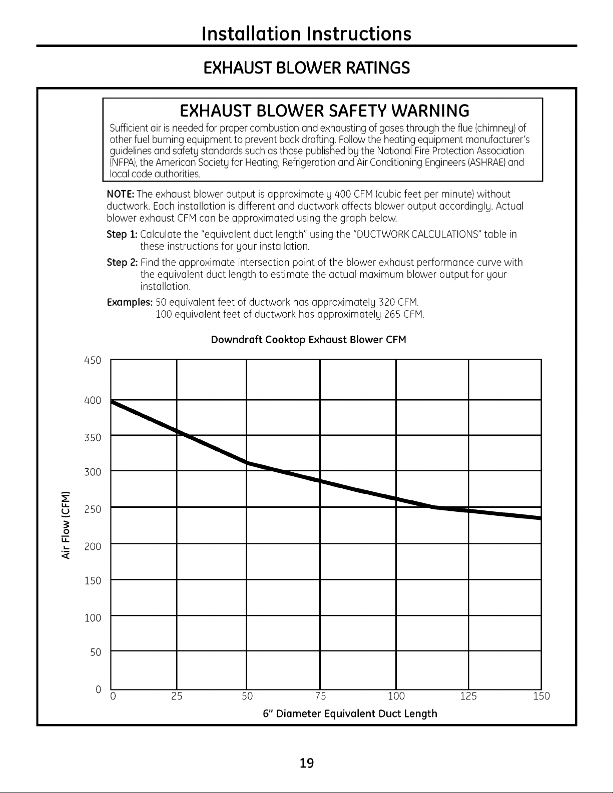
NOTE: The exhaust blower output is upproximutelg 400 CFM (cubic feet per minute) without
ductwork. Each installation is different and ductwork affects blower output uccordinglg. Actual
blower exhaust CFM can be approximated using the graph below.
Step 1: Calculate the "equivalent duct length" using the "DUCTWORK CALCULATIONS"table in
these instructions for your installation.
Step 2: Find the approximate intersection point of the blower exhaust performance curve with
the equivalent duct length to estimate the actual maximum blower output for your
installation.
Exomples: 50 equivalent feet of ductwork has approximately 320 CFM.
100 equivalent feet of ductwork has upproximutelg 265 CFM.
Downdroft Cooktop Exhoust Blower CFM
u_
U
O
lI
35O
300
250
200
150
i00
50
0
0 25 50 75 100
6" Diometer Equivolent Duct Length
125 150
19
Installation Instructions
DUCTWORK INSTALLATION
(Note: For planning purposes only.)
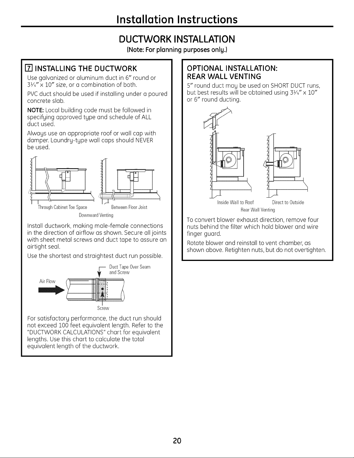
[] INSTALLING THE DUCTWORK
Use galvanized or aluminum duct in 6" round or
31/4" x 10" size, or a combination of both.
PVC duct should be used if installing under a poured
concrete slab.
NOTE: Local building code must be followed in
specifying approved type and schedule of ALL
duct used.
Always use an appropriate roof or wall cap with
damper. Laundry-type wall caps should NEVER
be used.
Through Cabinet Toe Space
BetweenFloorJoist
DownwardVenting
Install ductwork, making male-female connections
in the direction of airflow as shown. Secure all joints
with sheet metal screws and duct tape to assure an
airtight seal.
Use the shortest and straightest duct run possible.
Air Flow
-_ uct TapeOverSeam
andScrew
Screw
For satisfactory performance, the duct run should
not exceed 100 feet equivalent length. Refer to the
"DUCTWORK CALCULATIONS" chart for equivalent
lengths. Use this chart to calculate the total
equivalent length of the ductwork.
OPTIONAL INSTALLATION:
REAR WALL VENTING
5" round duct may be used on SHORT DUCT runs,
but best results will be obtained using 31/4" x 10"
or 6" round ducting.
InsideWall to Roof Direct to Outside
RearWall Venting
To convert blower exhaust direction, remove four
nuts behind the filter which hold blower and wire
finger guard.
Rotate blower and reinstall to vent chamber, as
shown above. Retighten nuts, but do not overtighten.
2O
Installation Instructions
UNPACKING THE COOKTOP/INSTALLING THE GASKET
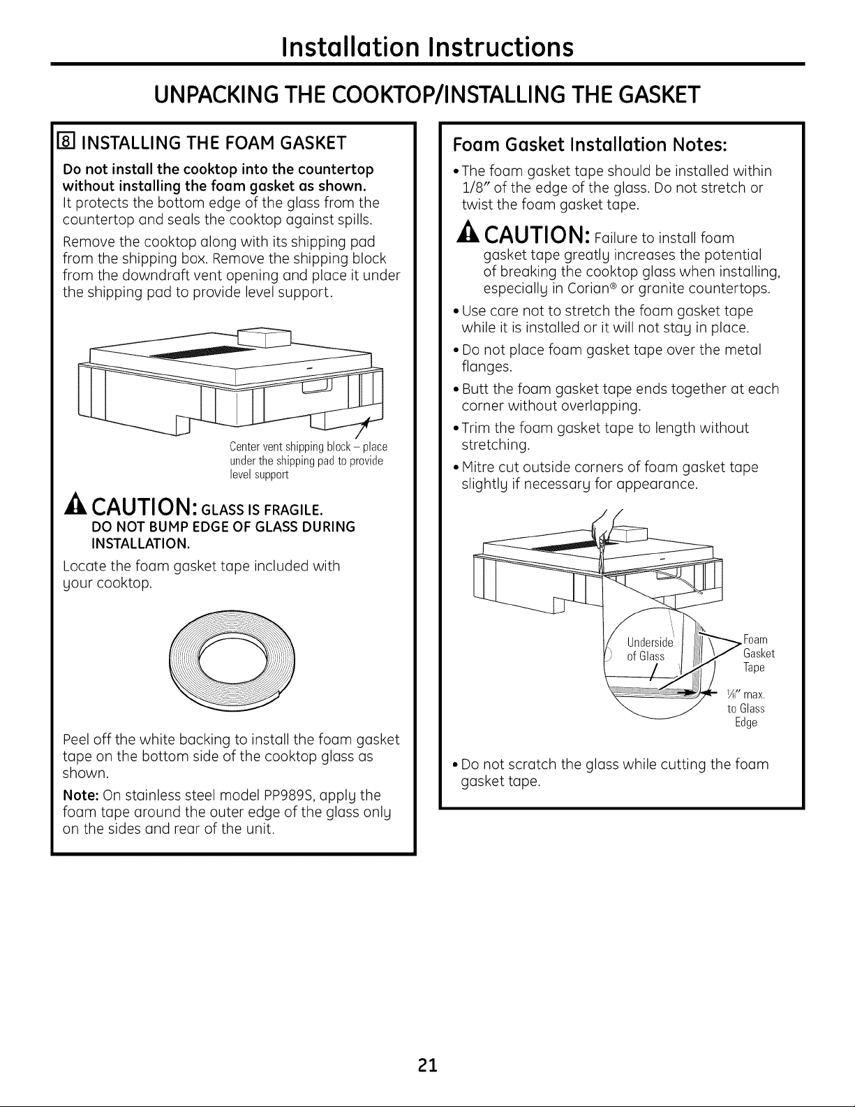
r81 INSTALLING THE FOAM GASKET
Do not install the cooktop into the countertop
without installing the foam gasket as shown.
It protects the bottom edge of the glass from the
countertop and seals the cooktop against spills.
Remove the cooktop along with its shipping pad
from the shipping box. Remove the shipping block
from the downdraft vent opening and place it under
the shipping pad to provide level support.
Centerventshippingblock- place
underthe shippingpadto provide
levelsupport
-& CAUTION: GLASS ISFRAGILE.
DO NOT BUMP EDGE OF GLASS DURING
INSTALLATION.
Locate the foam gasket tape included with
gour cooktop.
Peel off the white backing to install the foam gasket
tape on the bottom side of the cooktop glass as
shown.
Note: On stainless steel model PP989S, applg the
foam tape around the outer edge of the glass onlg
on the sides and rear of the unit.
Foam Gasket Installation Notes:
• The foam gasket tape should be installed within
1/8" of the edge of the glass. Do not stretch or
twist the foam gasket tape.
CAUTION: Failure to install foam
gasket tape greotlg increases the potential
of breaking the cooktop glass when installing,
especiollg in Corion ® or granite countertops.
• Use care not to stretch the foam gasket tape
while it is installed or it will not stag in place.
• Do not place foam gasket tape over the metal
flanges.
• Butt the foam gasket tape ends together at each
corner without overlapping.
• Trim the foam gasket tape to length without
stretching.
• Mitre cut outside corners of foam gasket tape
slightlg if necessorg for appearance.
/
Foam
Gasket
Tape
JJs s
Edge
• Do not scratch the glass while cutting the foam
gasket tape.
21
Installation Instructions
INSTALLING THE COOKTOP
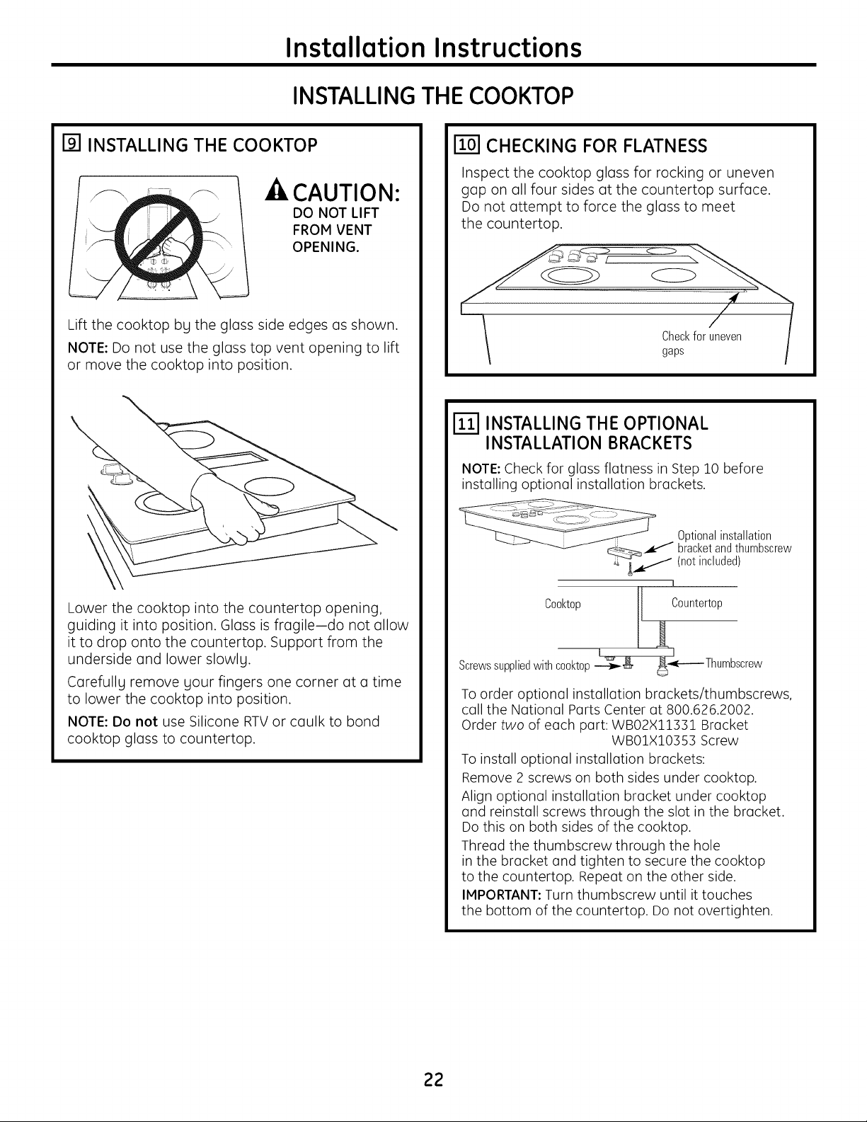
I_1 INSTALLING THE COOKTOP
CAUTION:
DO NOT LIFT
FROM VENT
OPENING.
Lift the cooktop by the glass side edges as shown.
NOTE: Do not use the glass top vent opening to lift
or move the cooktop into position.
Lower the cooktop into the countertop opening,
guiding it into position. Glass is fragileido not allow
it to drop onto the countertop. Support from the
underside and lower slowly.
Carefully remove your fingers one corner at a time
to lower the cooktop into position.
NOTE: Do not use Silicone RTV or caulk to bond
cooktop glass to countertop.
[] CHECKING FOR FLATNESS
Inspect the cooktop glass for rocking or uneven
gap on all four sides at the countertop surface.
Do not attempt to force the glass to meet
the countertop.
[_ INSTALLING THE OPTIONAL
INSTALLATION BRACKETS
NOTE: Check for glass flatness in Step 10 before
installing optional installation brackets.
Optionalinstallation
bracketandthumbscrew
(not included)
1
Cooktop _ Countertop
Screwssuppliedwithcooktop_ _gE----Thumbscrew
To order optional installation brackets/thumbscrews,
call the National Parts Center at 800.626.2002.
Order two of each part: WB02X11551 Bracket
WB01X10355 Screw
To install optional installation brackets:
Remove 2 screws on both sides under cooktop.
Align optional installation bracket under cooktop
and reinstall screws through the slot in the bracket.
Do this on both sides of the cooktop.
Thread the thumbscrew through the hole
in the bracket and tighten to secure the cooktop
to the countertop. Repeat on the other side.
IMPORTANT: Turn thumbscrew until it touches
the bottom of the countertop. Do not overtighten.
22
Installation Instructions
INSTALLING THE COOKTOP
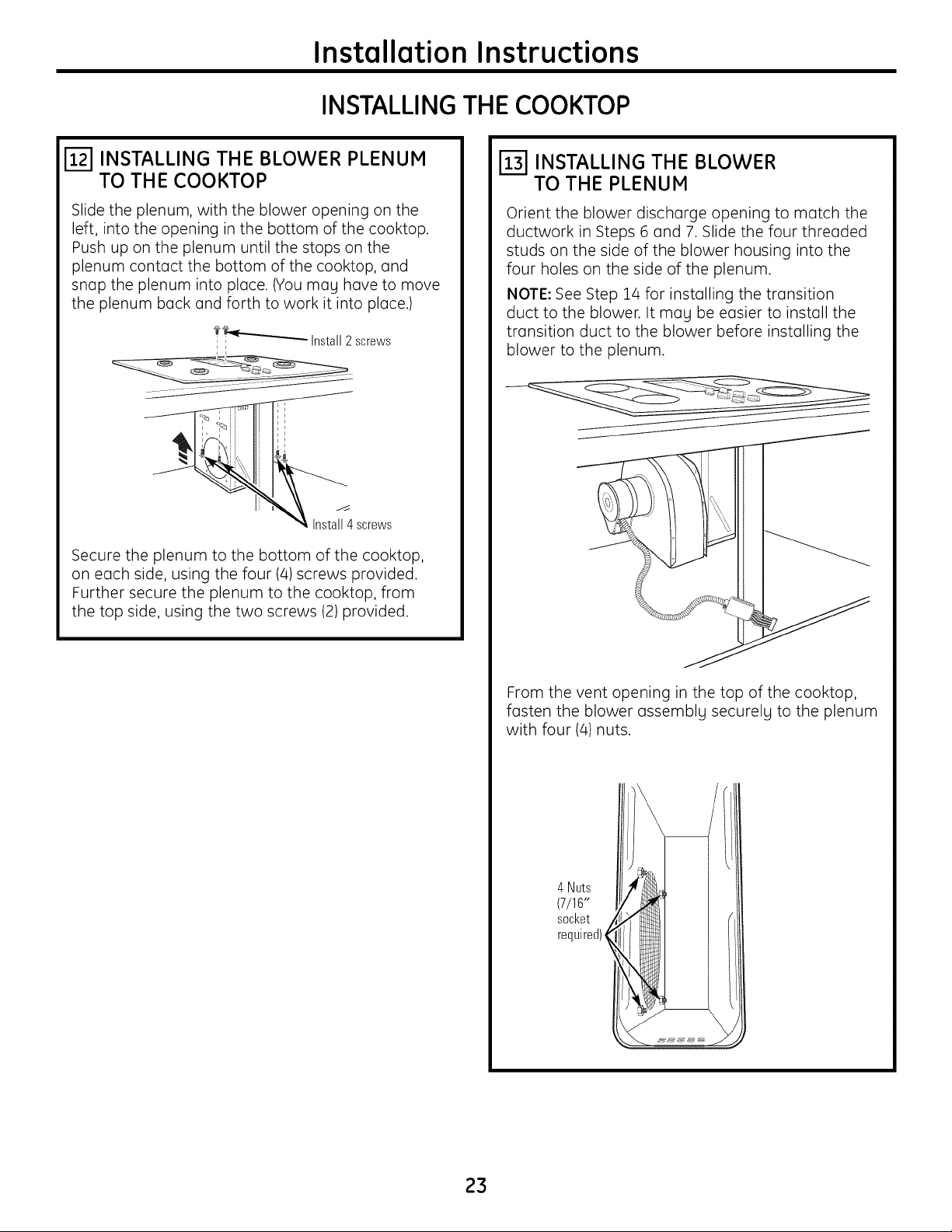
[_ INSTALLING THE BLOWER PLENUM
TO THE COOKTOP
Slide the plenum, with the blower opening on the
left, into the opening in the bottom of the cooktop.
Push up on the plenum until the stops on the
plenum contact the bottom of the cooktop, and
snap the plenum into place. (You mag have to move
the plenum back and forth to work it into place.)
? €_----:_"--""'-Install 2 screws
Secure the plenum to the bottom of the cooktop,
on each side, using the four (4) screws provided.
Further secure the plenum to the cooktop, from
the top side, using the two screws (2) provided.
[_ INSTALLING THE BLOWER
TO THE PLENUM
Orient the blower discharge opening to match the
ductwork in Steps 6 and 7. Slide the four threaded
studs on the side of the blower housing into the
four holes on the side of the plenum.
NOTE: See Step 14 for installing the transition
duct to the blower. It mag be easier to install the
transition duct to the blower before installing the
blower to the plenum.
J
From the vent opening in the top of the cooktop,
fasten the blower assemblg securelg to the plenum
with four (4) nuts.
4 Nuts
(7/16"
socket
required)_
23
Installation Instructions
INSTALLING THE COOKTOP
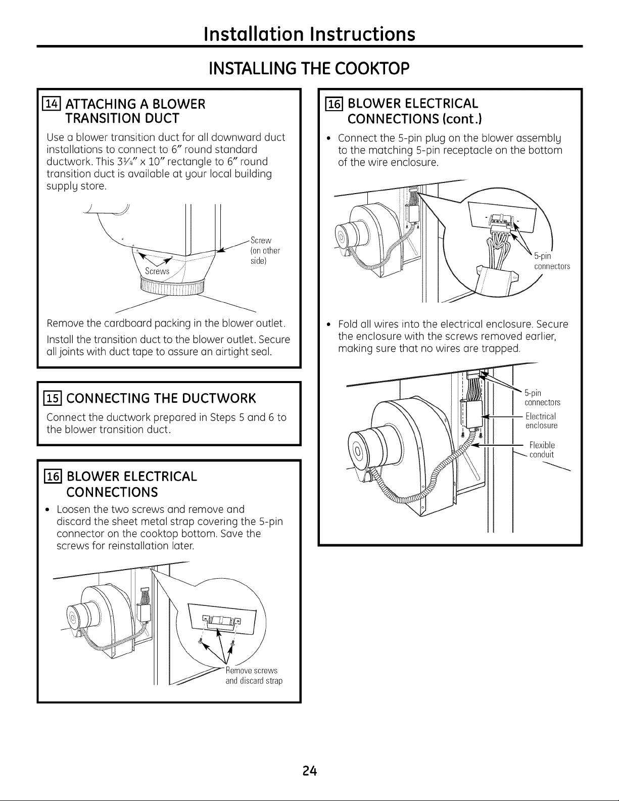
ATTACHING A BLOWER
TRANSITION DUCT
Use a blower transition duct for all downward duct
installations to connect to 6" round standard
ductwork. This 3VJ' x 10" rectangle to 6" round
transition duct is available at your local building
supply store.
Screw
(on other
side)
Remove the cardboard packing in the blower outlet.
Install the transition duct to the blower outlet. Secure
all joints with duct tape to assure an airtight seal.
I_] CONNECTING THE DUCTWORK
Connect the ductwork prepared in Steps 5 and 6 to
the blower transition duct.
BLOWER ELECTRICAL
CONNECTIONS
Loosen the two screws and remove and
discard the sheet metal strap covering the 5-pin
connector on the cooktop bottom. Save the
screws for reinstollotion later.
WS
II _/ anddiscardstrap
BLOWER ELECTRICAL
CONNECTIONS (cont.)
• Connect the 5-pin plug on the blower ossemblg
to the matching 5-pin receptacle on the bottom
of the wire enclosure.
5-pin
connectors
Fold all wires into the electrical enclosure. Secure
the enclosure with the screws removed earlier,
making sure that no wires are trapped.
5-pin
connectors
Electrical
II enclosure
_t,>_= Flexible
conduit
24
Installation Instructions
ELECTRICALCONNECTIONS
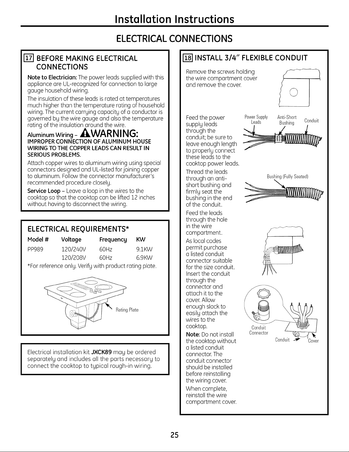
ETI BEFORE MAKING ELECTRICAL
CONNECTIONS
Note to Electrician: The power leads supplied with this
appliance are UL-recognized for connection to large
gauge household wiring.
The insulation of these leads is rated at temperatures
much higher than the temperature rating of household
wiring. The current carrying capacity of a conductor is
governed by the wire gauge and also the temperature
rating of the insulation around the wire.
Aluminum Wiring - _,WAR NING:
IMPROPER CONNECTION OF ALUMINUM HOUSE
WIRING TO THE COPPERLEADS CAN RESULTIN
SERIOUS PROBLEMS.
Attach copper wires to aluminum wiring using special
connectors designed and UL-listed for joining copper
to aluminum. Follow the connector manufacturer's
recommended procedure closely.
Service Loop - Leave a loop in the wires to the
cooktop so that the cooktop can be lifted 12 inches
without having to disconnect the wiring.
ELECTRICAL REQUIREMENTS*
Model # Voltege Frequency KW
PP989 120/240V 60Hz 9.1KW
120/208V 60Hz 6.9KW
*For reference only. Verify with product rating plate.
• Plate
Electrical installation kit J×CK89 may be ordered
separately and includes all the parts necessary to
connect the cooktop to typical rough-in wiring.
INSTALL 3/4" FLEXIBLE CONDUIT
Remove the screws holding
the wire compartment cover
and remove the cover.
Feed the power
supply leads
through the
conduit; be sure to
leave enough length
to properly connect
these leads to the
cooktop power leads.
Thread the leads
through an anti-
short bushing and
firmly seat the
bushing in the end
of the conduit.
Feed the leads
through the hole
in the wire
compartment.
As local codes
permit purchase
a listed conduit
connector suitable
for the size conduit.
Insert the conduit
through the
connector and
attach it to the
cover. Allow
enough slack to
easily attach the
wires to the
cooktop.
Note: Do not install
the cooktop without
a listed conduit
connector. The
conduit connector
should be installed
before reinstalling
the wiring cover.
When complete,
reinstall the wire
compartment cover.
PowerSupply Anti-Short
Leads Bushing Conduit
Bushing(FullySeated)
Conduit
Connector
Conduit
25
Installation Instructions
ELECTRICALCONNECTIONS
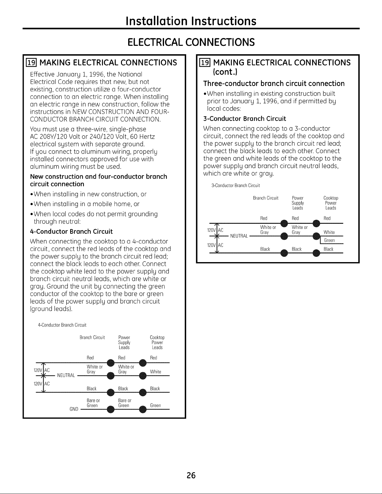
[] MAKING ELECTRICAL CONNECTIONS
Effective January 1, 1996, the National
Electrical Code requires that new, but not
existing, construction utilize a four-conductor
connection to an electric range. When installing
an electric range in new construction, follow the
instructions in NEW CONSTRUCTION AND FOUR-
CONDUCTOR BRANCH CIRCUIT CONNECTION.
You must use a three-wire, single-phase
AC 208Y/120 Volt or 2/40/120 Volt, 60 Hertz
electrical system with separate ground.
If you connect to aluminum wiring, properly
installed connectors approved for use with
aluminum wiring must be used.
New construction and four-conductor branch
circuit connection
• When installing in new construction, or
• When installing in a mobile home, or
• When local codes do not permit grounding
through neutral:
4-Conductor Branch Circuit
When connecting the cooktop to a 4-conductor
circuit, connect the red leads of the cooktop and
the power supply to the branch circuit red lead;
connect the black leads to each other. Connect
the cooktop white lead to the power supply and
branch circuit neutral leads, which are white or
gray. Ground the unit by connecting the green
conductor of the cooktop to the bare or green
leads of the power supply and branch circuit
(ground leads).
4-ConductorBranchCircuit
BranchCircuit
Power Cooktop
Supply Power
Leads Leads
Red Red Red
1_ White or
_ NEUTRAL Gray _ White
120VIAC
Black - Black Black
Bareor Bareor
Green
GND _ Green
MAKING ELECTRICAL CONNECTIONS
(cont.)
Three-conductor brunch circuit connection
• When installing in existing construction built
prior to January 1, 1996, and if permitted by
local codes:
3-Conductor Branch Circuit
When connecting cooktop to a 3-conductor
circuit, connect the red leads of the cooktop and
the power supply to the branch circuit red lead;
connect the black leads to each other. Connect
the green and white leads of the cooktop to the
power supply and branch circuit neutral leads,
which are white or gray.
3-ConductorBranchCircuit
Branch Circuit
Power Cooktop
Supply Power
Leads Leads
Red Red Red
1_C White or _ Whiteor 0
NEUTRAL Gray _ Gray _ _Vrhei:_
120V_AC Black _ Black _- Black
26
Installation Instructions
FINAL ASSEMBLY
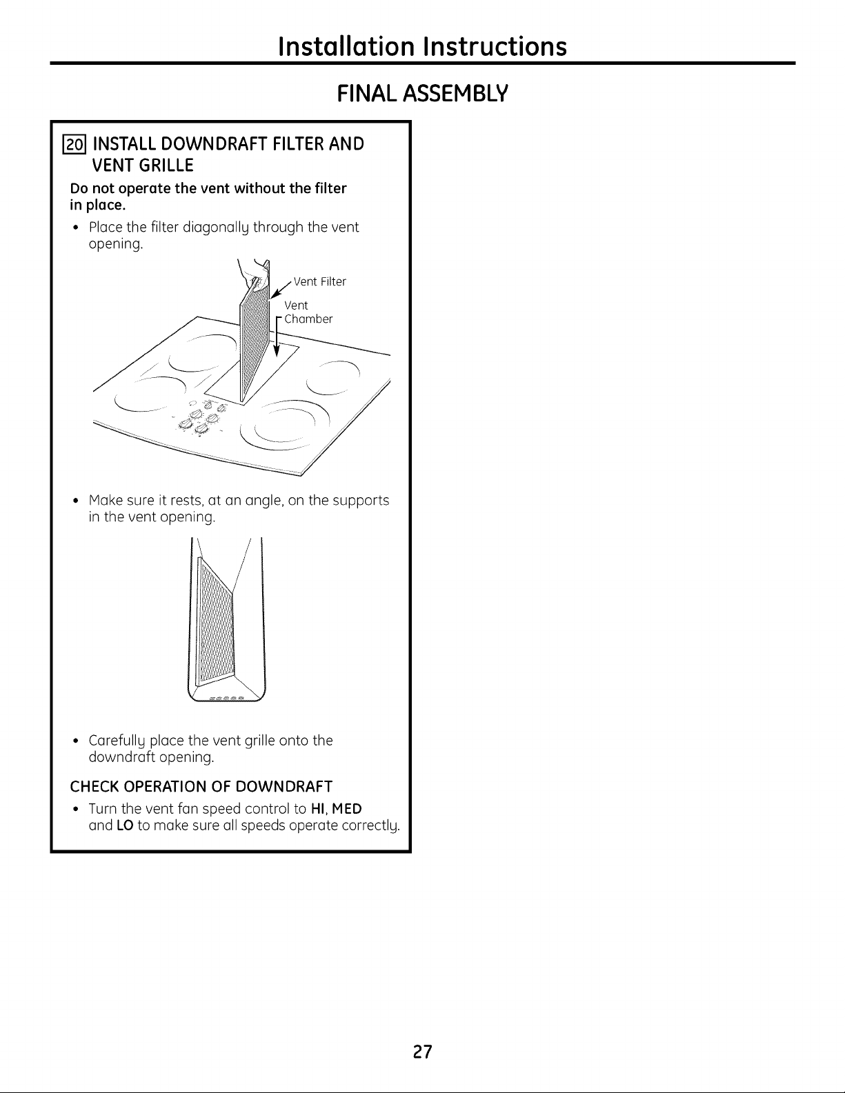
INSTALL DOWNDRAFT FILTER AND
VENT GRILLE
Do not operate the vent without the filter
in place.
• Place the filter diagonally through the vent
opening.
i Vent Filter
Vent
- Chamber
• Make sure it rests, at an angle, on the supports
in the vent opening.
° Carefullg place the vent grille onto the
downdraft opening.
CHECK OPERATION OF DOWNDRAFT
• Turn the vent fan speed control to HI, MED
and LO to make sure all speeds operate correctlg.
27
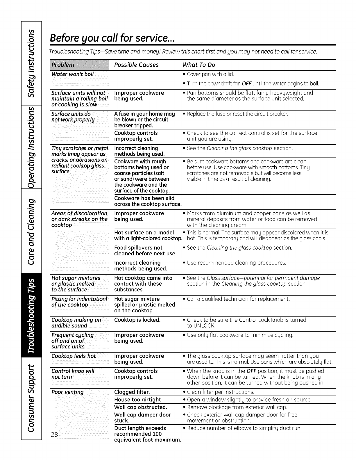
Before gou call for service...
Troubleshooting TipsJSave time and money! Review this chart first and you may not need to coil for service.
Possible Causes What To Do
Water won't boil • Cover pan with a lid.
• Turn the downdraft fan OFFuntil the water begins to boil.
Surface units willnot Improper cookware • Pan bottoms should be flat, fairly heavyweight and
maintain a rolling boil being used. the same diameter as the surface unit selected.
or cooking is slow
Surface units do A fuse in gour home mag • Replacethe fuse or reset the circuit breaker.
not work properly be blown or the circuit
breaker tripped.
Cooktop controls • Check to see the correct control is set for the surface
improperlg set. unit you are using.
Tiny scratches or metal Incorrect cleaning • See the Cleaning the glass cooktop section.
marks (may appear as methods being used.
cracks)or abrasions on Cookware with rough • Be sure cookware bottoms and cookware are clean
radiant cooktopglass bottoms being used or before use. Use cookware with smooth bottoms. Tiny
surface coarse particles (salt scratches are not removable but will become less
or sand) were between visible in time as a result of cleaning.
the cookware and the
surface of the cooktop.
Cookware has been slid
across the cooktop surface.
Areas of discoloration Improper cookware • Marks from aluminum and copper pans as well as
or dark streaks on the being used. mineral deposits from water or food con be removed
cooktop with the cleaning cream.
Hot surface on a model • This is normal. The surface may appear discolored when it is
with a light-colored cooktop, hot. This is tempora% and will disappear as the gloss cools.
Food spillovers not • See the Cleaning the glass cooktop section.
cleaned before next use.
Incorrect cleaning • Use recommended cleaning procedures.
methods being used.
Hot sugar mi_ures Hot cooktop came into • See the Glass surface potential for permaent damage
or plastic melted contact with these section in the Cleaning the glass cooktop section.
to the surface substances.
Pitting (orindentation) Hot sugar mixture • Call a qualified technician for replacement.
of the cooktop spilled or plastic melted
on the cooktop.
Cooktop making an Cooktop is locked. • Check to be sure the Control Lock knob is turned
audible sound to UNLOCK.
Frequent cgcling Improper cookware • Use only flat cookware to minimize cycling.
off and on of being used.
surface units
Cooktop feels hot Improper cookware • The gloss cooktop surface may seem hotter than you
being used. are used to. This is normal. Use pans which are absolutely flat.
Control knob will Cooktop controls • When the knob is in the OFFposition, it must be pushed
not turn improperlg set. down before it can be turned. When the knob is in any
other position, it can be turned without being pushed in.
Poor venting Clogged filter. • Clean filter per instructions.
House too airtight. • Open a window slightly to provide fresh air source.
Wall cap obstructed. • Remove blockage from exterior wall cap.
Wall cap damper door • Check exterior wall cap damper door for free
stuck, movement or obstruction.
Duct length exceeds • Reduce number of elbows to simplify duct run.
28 recommended 100
equivalent foot maximum.
GE Service Protection Plus'"
GE, a name recognized worldwide for quality and dependability together with Assurant Solutions, offers you
Service Protection PlusT"--comprehensive protection on your appliances.*
Benefits Include:
• Prompt, reliable service from GEAuthorized Servicers
• Convenient hours designed to suit your busy schedule
• Quality replacement parts
• The dependability of GE, a name recognized and trusted worldwide
• Ask about our interest-free payment plans
With Service Protection Plus gou can expect:
• An extended service plan that limitsunexpected repair bills
• Service coverage for most major brands
• Unlimited service calls for the length of your contract, or credit toward a replacement product
• Service coverage for covered operating parts and labor on appliances and home electronics that fail during normal single family
household use
• Your satisfaction is our goal. We strive to provide you with excellent service in a professional and timely manner.
Place gour confidence in GE and call us in the U.S. toll-free at 1.800.626.2224 for more information.
*Most brands covered up to 15 gears old in the continental U.S.
SPP is a trademark of General Electric Compang.
Please place in envelope and mail to:
General Electric Company
Warrantg Registration Department
P.O.Box 32150
Louisville,KV 40232-2150
29
Consumer Product Ownership Registration
Dear Customer:
Thank you for purchasing our product and thank you for placing your confidence in us.
We are proud to have you as a customer!
Follow these three steps to protect your new appliance investment:
Complete and mail
gour Consumer
Product Ownership
Registration todag.
Have the peace of
mind of knowing we
can contact you in
the unlikely event of
a safetg modification.
After mailing the
registration below,
store this document
in a safe place. It
contains information
you will need should
you require service.
Our service number is
800 GE CARES
(800.432.2737).
Read your Owner's
Manual carefully.
It will help you
operate your new
appliance properly.
Model Number Serial Number
Important: If gou did not get a registration card with gour
product, detach and return the form below to
ensure that gour product is registered, or register
online at ge.com.
Consumer Product Ownership Registration
_.c.uLh.%e.....
@
Model Number
,,,,,,,,,,I I,
Serial Number
I I I I I I
Hr.Zi Hs. Zi Hrs. Zi Hiss Zi
First J
Name I I I I I I
I I I I LastName I I I
I I I I I I I I
Street
I
Address I I I I I I I I I I I I I I I I I I I I I
Apt.#1 II I I I I I I
E-mail Address*
I
Citg I I I
Date Placed
InUse I I
Month I
I I I I I I
Dagl I I Yearl
Zip
I I I Statel I J Code l I I l I
Phone
Numberl I, I-I,, I-I , , ,
GE Consumer & Industrial
Appliances
General Electric Compang
Louisville, KY40225
ge.com
30
* Please provide gour e-mail address to receive, via e-mail, discounts, special offers and other important
communications from GE Appliances (GEA).
i. Check here if gou do not want to receive communications from GEA'scarefullg selected partners.
FAILURETOCOMPLETEAND RETURNTHIS CARDDOESNOT DIMINISH YOURWARRANTY RIGHTS.
For information about GEA's privacg and data usage policg, go to ge.com and click on "Privacg Policg"
or call 800.626.2224.
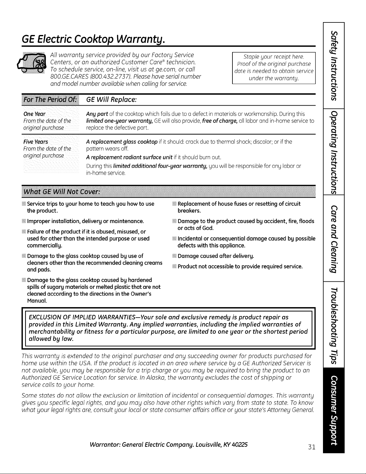
GE Electric Cooktop Warranty.
All warranty service provided by our Factory Service
Centers, or on authorized Customer Core ®technician.
To schedule service, on-line, visit us at ge.com, or call
800.GE.CARES (800./432.2737). Please have serial number
and model number available when calling for service.
Staple Four receipt here.
Proof o1:the original purchase
date is needed to obtain service
under the warrant F.
One Year
From the date of the
original purchase
Any part of the cooktop which foils due to o defect in materiuls or workmanship. During this
limited one-year warranty, GEwill also provide,free of charge,all labor and in-home service to
replace the defective part.
Five Years
Fromthe date of the
original purchase
A replacement glass cooktop if it should: crack due to thermal shock; discolor; or if the
pattern wears off.
A replacement radiant surface unit if it should burn out.
During this limited additional four-year warranty, gou will be responsiblefor ang labor or
in-home service.
Service trips to gour home to teach gou how to use
the product.
installation, deliverg or maintenance.
Failure of the product if it is abused, misused, or
used for other than the intended purpose or used
commerciallg.
Damage to the glass cooktop caused bg use of
cleaners other than the recommended cleaning creams
and pads.
Damage to the glass cooktop caused bg hardened
spills of sugarg materials or melted plastic that are not
cleaned according to the directions in the Owner's
Manual.
Replacement of house fuses or resetting of circuit
breakers.
Damage to the product caused bg accident, fire, floods
or acts of God.
Incidental or consequential damage caused bg possible
defects with this appliance.
Damage caused after deliverg.
Product not accessible to provide required service.
EXCLUSION OF IMPLIED WARRANTIES--Your sole and exclusive remedy is product repair as
provided in this Limited Warranty. Any implied warranties, including the implied warranties of
merchantability or fitness for a particular purpose, are limited to one year or the shortest period
allowed by law.
This warranty is extended to the original purchaser and any succeeding owner for products purchased for
home use within the USA. If the product is located in on area where service by a GEAuthorized Servicer is
not available, you may be responsible for a trip charge or you may be required to bring the product to on
Authorized GE Service Location for service. In Alaska, the warranty excludes the cost of shipping or
service calls to your home.
Some states do not allow the exclusion or limitation of incidental or consequential damages. This warranty
gives you specific legal rights, and you may also have other rights which vary from state to state. To know
what your legal rights ore, consult your local or state consumer affairs office or your state's Attorney General.
Warrantor: General Electric Company. Louisville, KV 40225 31

Consumer Support.
GEAppliances Website
Have a question or need assistance with your appliance? Try the GEAppliances Website 24 hours a day,
any day of the year! For greater convenience and faster service, you can now download Owner's Manuals,
order parts or even schedule service on-line.
ge.com
Schedule Service
Expert GErepair service is only one step away from your door. Get on-line and schedule your service at
your convenience any day of the year! Or call 800.GE.CARES(800.432.2737)during normal business hours.
ge.com
Real Life Design Studio ge.com
GEsupports the Universal Design concept-products, services and environments that can be used by
people of all ages, sizesand capabilities. We recognizethe need to design for a wide range of physical and
mental abilities and impairments. For details of GE'sUniversal Designapplications, including kitchen design ideas
for people with disabilities,check out our Website today. Forthe hearing impaired, please call 800.TDD.GEAC
(800.833./4322).
Extended Warranties
Purchasea GEextended warranty and learn about special discounts that are available while your warranty
is still in effect. You can purchase it on-line anytime, or call 800.626.222/4during normal business hours.
GEConsumer Home Serviceswill still be there after your warranty expires.
ge.com
Ports and Accessories
ge.com
Individuals qualified to service their own appliances can have parts or accessoriessent directly to their homes
(VISA,HasterCard and Discovercards are accepted).Order on-line today, 2/4hours every day or by phone
at 800.626.2002during normal businesshours.
Instructions contoined in this munuul coverprocedures to be performed by uny user. Other servicing
generully should be referred to quulified service personnel. Cuution must be exercised,since improper
servicing muy cuuseunsofe operation.
Contact Us
If you are not satisfiedwith the service you receive from GE,contact us on our Website with all the details
including your phone number, or write to: General Hanager, Customer Relations
GEAppliances,Appliance Park
Louisville,KY/40225
ge.com
Register Your Appliance
Register your new appliance on-line--at your convenience! Timely product registration will allow for
enhanced communication and prompt service under the terms of your warranty, should the need arise.
Youmay also mail in the pre-printed registration card included in the packing material.
ge.com
Printed in the United States
0
ge.com
A
C_
L_
-0
C
0
-(3
CD
C
QJ
-0
C
U
V)
QJ
-0
C
,0
o i
U
C_
i
C
GJ
>
GJ
c-
C_
® i
-0
C_
L_
Instrucciones de seguridad ........ 2-5
Instrucciones de operaci6n
Caracteristicas de su estufa ................ 6
Ideas sobre las piezas de cocina ........... 9
Limitador de temperatura .................. 8
Quemador de puente ...................... 8
Sistema de ventilaci6n de la estufa ......... 8
Unidades de superficie ................... 7, 8
Unidad de superficie doble ................. 8
Cuidado y limpieza
Botones de control ........................ 10
Estufa de vidrio ........................ 11, 12
Filtro de ventilaci6n ....................... 10
Sistema de ventilaci6n .................... 10
Instrucciones de instalaci6n
C6mo desempacar la estufa .......... 14, 21
C6mo instalar la estufa ............... 22-24
C6mo instalar la junta ..................... 21
Cone×iones el6ctricas ................ 24-26
Ensambladura final ....................... 27
indices de soplado de escape ............. 19
Precauciones de seguridad ............... 13
Preparaci6n ........................... 15-17
Red de conductos ................. 17-20, 24
Ideas sabre la identificaci6n
y soluci6n de averias ................. 28
Apoyo a! consumidor
Apoyo al consumidor ..................... :32
Garantia .................................. ,31
Escriba el n(_mero de modelo y
de serie aquk
Modelo #
Serie #
Encuentre estos nOmeros en una
etiqueta debajo de la estufa, en el
lado de la ccimara de ventilaci6n.
PP989
49-805:17-:1 09-08JR
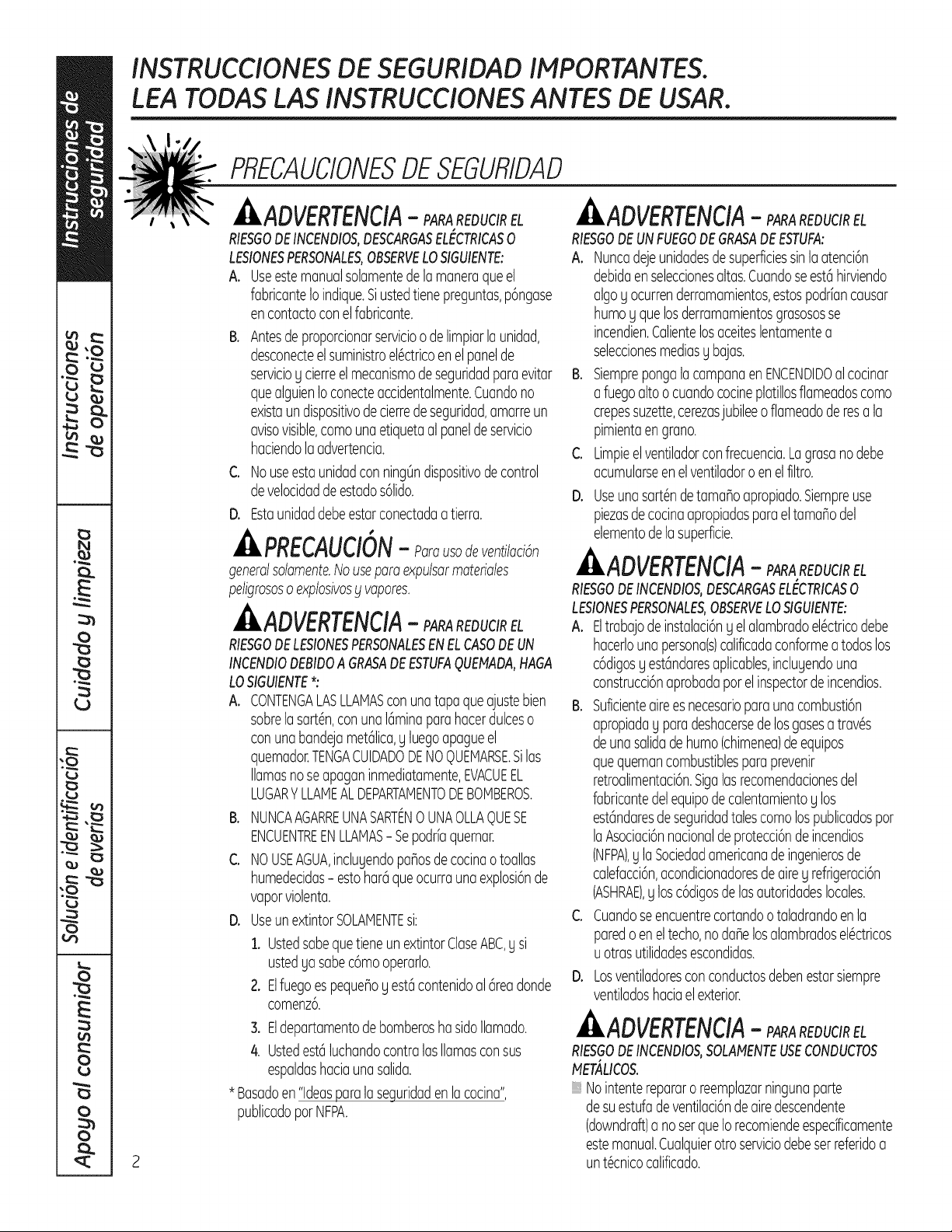
INSTRUCCIONES DE SEGURIDAD IMPORTANTES.
LEA TODAS LAS INSTRUCCiONES ANTES DE USAR.
PRECAUCIONESDESEGURIDAD
kADVERTENCIA- SARAREOUaREL
RIESOOOEINCENOIOS,OESCAROASEL CTRICASo
LESIONESPERSONALES,OBSERVELOSIGUIENTE:
A. Useestemanualsolamentede la maneraqueel
fabricanteIoindique.Siustedtienepreguntas,p6ngase
encontactoconelfabricante.
C,
Antesdeproporcionarservicioodelimpiarlaunidad,
desconecteelsuministroel@tricoenelpanelde
servicioycierreelmecanismodeseguridadparaevitar
quealguienIoconecteaccidentalmente.Cuandono
existaundispositivodecierredeseguridad,amarreun
avisovisible,comounaetiquetaalpaneldeservicio
haciendolaadvertencia.
NouseestaunidadconningOndispositivodecontrol
develocidadde estados61ido.
D. Estaunidaddebeestarconectadaa tierra.
, PRECAUCI@N- Parausodeventilaci6n
generalsolamente.Nousepara expulsarmateriales
peligrososoexplosivosblvapores.
ADVERTENCIA- SARAREDUCIREL
RIESGODELESIONESPERSONALESENELCASODEUN
INCENDIODEBIDOA GRASADEESTUFAQUEt4ADA,HAGA
LOSIGUIENTE*:
A. CONTENGALASLLAMAScon unatapaqueajustebien
sobrelasart6n,conuna16minaparahacerdulceso
conuna bandejamet61ica,y luegoapagueel
quemador.TENGACUIDADODENOQUEMARSE.Silas
llamasnoseapaganinmediatamente,EVACUEEL
LUGARYLLAMEALDEPARTAMENTODEBOMBEROS.
B. NUNCAAGARREUNASARTENOUNAOLLAq)UESE
ENCUENTREENLLAMAS- Sepod@quemar.
C NOUSEAGUA,incluyendopar_osdecocinaotoallas
humedecidas- estohar6queocurraunaexplosi6nde
vaporviolenta.
D. UseunextintorSOLAIVlENTEsi:
1. Ustedsabequetieneun extintorClaseABC,g si
ustedya sabec6mooperarlo.
2. Elfuegoespequer_oy est6contenidoal 6readonde
comenz6.
3. Eldepartamentode bomberoshasidoIlamado.
4. Ustedestciluchandocontralasllamasconsus
espaldashaciaunasalida.
* Basadoen"Ideasparalaseguridaden lacocina",
publicadopot NFPA.
ADVERTENCIA- SARAREOUCIREL
RIESGODEUNFUEGODEGRASADEESTUFA:
A. Nuncadejeunidadesdesuperficiessinla atenci6n
debidaenseleccionesaltas.Cuandose est(ihirviendo
algoy ocurrenderramamientos,estospodriancausar
humoy quelosderramamientosgrasososse
incendien.Calientelosaceiteslentamentea
seleccionesmediasy bajas.
B. Siemprepongalacampanaen ENCENDIDOal cocinar
afuegoalto o cuandococineplatillosflameadoscomo
crepessuzette,cerezasjubileeo flameadoderesa la
pimientaengrano.
C. Limpieelventiladorconfrecuencia.Lagrasanodebe
acumularseen elventiladoro enel filtro.
D. Useunasart6ndetamar_oapropiado.Siempreuse
piezasdecocinaapropiadasparaeltamaflodel
elementodelasuperficie.
ADVERTENCIA- SARAREDUCIREL
RIESGODEINCENDIOS,DESCARGASELECTRICAS0
LESIONESPERSONALES,OBSERVELOSIGUIENTE:
A. Eltrabajode instalaci6ny el alambradoel6ctricodebe
hacerlounapersona(s)calificadaconformea todoslos
c6digosy estcindaresaplicables,incluyendouna
construcci6naprobadapot elinspectorde incendios.
B. Suficienteaireesnecesariopara unacombusti6n
apropiaday paradeshacersede losgasesatrav6s
deunasalidadehumo(chimenea)de equipos
quequemancombustiblesparaprevenir
retroalimentaci6n.Sigalasrecomendacionesdel
fabricantedelequipode calentamientoy los
estcindaresde seguridadtalescomo lospublicadospor
laAsociaci6nnacionaldeprotecci6nde incendios
(NFPA),y laSociedadamericanade ingenierosde
calefacci6n,acondicionadoresde airey refrigeraci6n
(ASHRAE),y losc6digosdelasautoridadeslocales.
C. Cuandoseencuentrecortandoo taladrandoenla
paredo eneltecho,nodar_elosalambradosel6ctricos
uotrasutilidadesescondidas.
D. Losventiladoresconconductosdebenestarsiempre
ventiladoshaciaelexterior.
ADVERTENCIA- SARAREDUCIREL
RIESGODEINCENDIOS,SOLAHENTEUSECONDUCTOS
t4ETALICOS.
Nointenterepararo reemplazarningunaparte
desuestufade ventilacidndeairedescendente
(downdraft)a no serqueIorecomiendeespecfficamente
estemanual.Cualquierotroserviciodebeserreferidoa
unt6cnicocalificado.
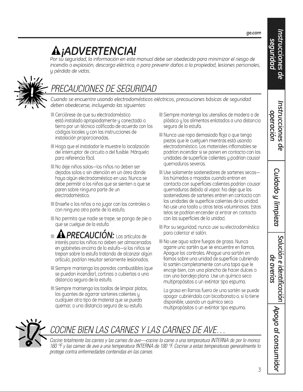
ge.com
iADVERTENCIA!
Par su seguridad, la informaci6n en este manual debe set obedecida para minimizar el riesgo de
incendio o explosion, descarga eldctrica, o para prevenir dahos a la propiedad, lesiones personales,
g p4rdida de vidas.
PRECAUCIONESDESEGURIDAD
Cuando se encuentre usando electrodomdsticos eldctricos, precauciones bdsicas de seguridad
deben obedecerse, inclugendo las siguientes:
: Cerci6resede que su electrodom6stico
est6 instalado apropiadamente g conectado a
tierra par un t6cnico calificado de acuerdo con los
c6digos locales g con las instrucciones de
instalaci6n proporcionadas.
: Haga que el instalador le muestre la Iocalizaci6n
del interruptor de circuito o del fusible. M6rquelo
para referencia f6cil.
: No deje nihos solos-los nifios no deben ser
dejados solos o sin atenci6n en un 6rea donde
haga algOnelectrodom6stico en usa. Nunca se
debe permitir a los nifios que se sienten o que se
paren sabre ninguna parte de un
electrodom6stico.
: Ense_ea los ni_os a nojugar con los controles o
con ninguna otra parte de la estufa.
: No permita que nadie se trepe, se ponga de pie o
que se cuelgue de laestufa.
PRECAUCION:Losartfculos de
inter6spara los niflos no deben ser almacenados
en gabinetes encima de laestufa-si los niflos se
trepan sabre la estufa tratando de alcanzar algOn
artfculo, podr[an resultar seriamente lesionados.
: Siempre mantenga las paredes combustibles (que
se puedan incendiar),cortinas o cubiertas a una
distancia segura de la estufa.
: Siempremantengalastoallasdelimpiarplatos,
losguantesdeagarrarsartenescalientesg
cualquierotrotipo dematerialquesepueda
quemar,a una distanciaseguradesu estufa.
Siempre mantenga los utensiliosde madera o de
pl6stico g los alimentos enlatados a una distancia
segura de la estufa.
Nunca use ropa demasiado floja o que tenga
piezasque le cuelguen mientras est6 usando
electrodom6stico. Los materiales inflamables se
podr[an incendiar si se ponen en contacto con las
unidades de superficie calientes g podrfan causar
quemaduras severas.
Usesolamente sostenedoresde sartenes secos-
los hOmedoso mojados cuando entran en
contacto con superficies calientes podr[an causar
quemaduras debido al vapor. No deje que los
sostenedoresde sartenes entren en contacto con
las unidades de superficie calientes de la unidad.
No use una toalla u arras telas voluminosas. Estas
telas se podr[an encender al entrar en contacto
con las superficies de la unidad.
Parsu seguridad, nunca use su electrodom6stico
para calentar el sal6n.
Nouseaguasabrefuegosdegrasa.Nunca
agarreunasart6nqueseencuentreen llamas.
Apagueloscontroles.Ahogueunasart6nen
llamassabreuna unidaddesuperficiecubriendo
la sart6ncompletamenteconunatapa que le
encajebien,conuna planchade hacerdulceso
conuna bandejaplana.Useunquimicoseco
multiprop6sitoso unextintortipoespuma.
Lagrasaenllamasfuerade unasart6nse puede
apagarcubri6ndolaconbicarbonatoo,si Iotiene
disponible,usandounquimicoseco
multiprop6sitoso unextintortipoespuma.
COCINEBIENLASCARNESYLASCARNESDEAVE...
Cocinetotalmentelas camesy las camesde ave_ocine la came a una temperaturaINTERNAdepot Io menos
160°Fy/as camesde ave a una temperaturaINTERNAde 180OF.Cocinara estastemperaturasgeneralmenteIo
protege contraenfermedadescontenidasen /ascames.
3
INSTRUCCIONES DE SEGURIDAD ltdPORTANTES.
LEA TODAS LAS INSTRUCCiONES ANTES DE USAR.
iADVERTENCIA!
PfiECAUCIONESDESEGUfilDAD
: No permito que groso de cocinor u otros
moterioles inflomobles se ocumulen sabre
Io estufo.
: No toque los unidodes de superficie. Estos
superficies podrfon estor Iosuficientemente
colientes poro quemor ounque est6n negros g no
porezcon estor colientes. Duronte g despu6sdel
usa,no toque, o permito que ninguno ropo u otros
moterioles inflomobles se pongon en contocto
con los unidodes o con los @eospr6ximos o los
unidodes de superficie;permito que tronscurro
tiempo suficiente poro que se enfrfen primero.
Potenciolmentelos superficies colientes inclugen
Io estufo g los @eosen proximidod inmedioto o Io
estufo.
: Paraminimizor la posibilidod de quemaduros, de
ignici6n de moterioles inflomobles g de derromes,
Io monUode Io sort6n u alia debe volteorse hocio
el centro de Io estufo sin extenderlo sabre
cuolquier otro unidod de superficie cercono.
: Siempre opogue el control de Io unidod de
superficie antes de remover sus piezosde cocino.
: Use sartenes de tamano apropiado-Seleccione
sartenes que tengan el fondo Iosuficientemente
piano coma para cubrir la unidad de superficie
que se encuentra calentando el elemento. Elusa
de piezasde cocina demasiado pequeBas
expondr6 una porci6n de la unidad de superficie
un contacto directo que podr[a resultaren Io
ignici6n de alguna ropa. La relaci6n apropiada
entre las sartenes g el quemador tambi6n
mejorar6 la eficiencia.
: Nunca deje unidades de superficies sin la atenci6n
debida en seleccionesaltas. Cuando se est6
hirviendo alga g ocurren derramamientos, estos
podr[an causar humo y que los derramamientos
grasosos se incendien.
: Solamente ciertos tipos de vidrios,cer6micas,
vasijas de barro cocidas g arras vasUasglaseadas
son apropiadas para cocinar sabre la estufa;arras
se podrian romper debido a cambios r@idos en la
temperatura.
: Pongaatenci6na losalimentosqueseencuentre
friendoa seleccionesdecaloraltasy medias.
: Losalimentos que se van a frefr deberfan secarse
tanto coma sea posible. Elhielo g la humedad en
comidas frescaspueden causar un derrame de
aceite.
: Usepocoaceiteparaunafritura efectivanomug
profunda.Llenarla sart6ncondemasiadoaceite
podriacausarqueocurranderramescuandolos
alimentosseanagregados.
: Si se dispone a usar una combinaci6n de
aceites y grasas para cocinar, m6zclelosantes de
calentarlos,o derrita las grasas lentamente.
: Siemprecaliente las grasas lentamente y vigflelas
mientras se calientan.
: Use un term6metro de grasa de profundidad
siempre que sea posible para prevenir que la
grasa se sobrecaliente m6s alk] del punto de
inflamaci6n.
: Nunca trate de mover una sart6n que contenga
grasa caliente,especialmente una sart6n que
contenga mucha grasa caliente. Esperehasta que
la grasa se enfrfe.
: No almacene materiales inflamables cerca de
la estufa.
: Mantengalaparrilladeventilaci6ng losfiltrosde
grasalimpiosparamantenerunabuena
ventilaci6ng evitarfuegosdegrasa.
: No almacene o use materiales combustibles,
gasolina u otros vapores inflamables g Ifquidosen
las proximidades de esteo cualquier otro
electrodom6stico.
: Limpiesolamentelaspartesespecificadasen este
Manualdelpropietario.
: No deje productos de papel, utensiliosde cocina o
alimentos sabre la estufa cuando no est6 siendo
usada.
: Mantengalaestufalimpiay libredeacumulaci6n
degrasao derramesque sepuedanencender.
: Nunca caliente comida enlatada cerrada. La
presi6n en su interior podrfa causar que ocurra
una explosi6n y que haya lesiones.
: Nunca deje latas ojarras de grasa sabre o
pr6ximo a su estufa.
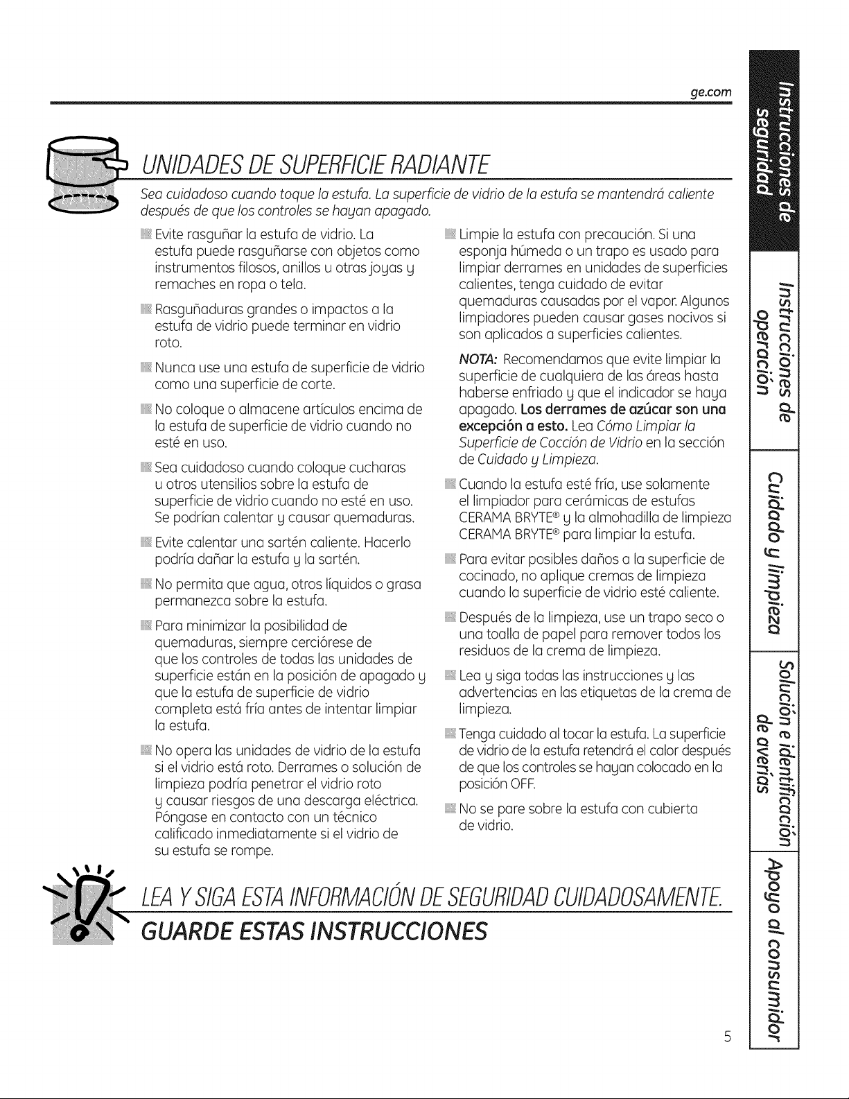
_e.com
UNIDADESDESUPERFICIERADIANTE
Sea cuidadoso cuando toque la estufa. La superficie de vidrio de la estufa se mantendrd caliente
despu4s de que los controles se ha_lan apagado.
Evite rasgunar la estufa de vidrio. La
estufa puede rasgunarse con objetos como
instrumentos filosos, anillos u otrasjogas g
remaches en ropa o tela.
RasguBadurasgrandes o impactos a la
estufa de vidrio puede terminar en vidrio
roto.
iiiiiil
iiiiiiili_
Nunca use una estufa de superficie de vidrio
como una superficie de corte.
No coloque o almacene articulos encima de
la estufa de superficie de vidrio cuando no
est6 en uso.
iiiiiil
iiiiiiili_
iiiiiiili_
iiiiiiili_
Sea cuidadoso cuando coloque cucharas
u otros utensilios sobre la estufa de
superficie de vidrio cuando no est6 en uso.
Se podrian calentar g causar quemaduras.
Evite calentar una sart6n caliente. Hacerlo
podria daBar la estufa g la sart6n.
No permita que agua, otros liquidos o grasa
permanezca sobre la estufa.
Paraminimizar la posibilidad de
quemaduras, siempre cerci6resede
que los controles de todas las unidades de
superficie est6n en la posici6n de apagado g
que la estufa de superficie de vidrio
completa est6 fria antes de intentar limpiar
la estufa.
iiiiiil
No opera las unidades de vidrio de la estufa
si el vidrio est6 roto. Derrames o soluci6n de
limpieza podria penetrar el vidrio roto
g causar riesgos de una descarga el6ctrica.
P6ngase en contacto con un t6cnico
calificado inmediatamente si el vidrio de
su estufa se rompe.
iiiil}i
iiiiiiili_
iiiiiiili_
iiiiiiili_
iiiiiiili_
iiiiiiili_
iiiiiiili_
Limpie la estufa con precauci6n. Si una
esponja hOmedao un trapo es usado para
limpiar derrames en unidades de superficies
calientes,tenga cuidado de evitar
quemaduras causadas pot el vapor.Algunos
limpiadores pueden causar gases nocivos si
son aplicados a superficies calientes.
I',IOTA: Recomendamos que evite limpiar la
superficie de cualquiera de las 6teas hasta
haberse enfriado g que el indicador se haga
apagado. Los derrames de az_car son una
excepd6n a esto. Lea C4mo Limpiar la
Superficie de Cocci4n de Vidrio en la secci6n
de Cuidado y Limpieza.
Cuando la estufa est6 fria, use solamente
el limpiador para cer6micas de estufas
CERAMA BRYTE® g la almohadilla de limpieza
CERAMA BRYTE® para Iimpiar la estufa.
Para evitar posibles danos a la superficie de
cocinado, no aplique cremas de limpieza
cuando la superficie de vidrio est6 caliente.
Despu6s de la limpieza, use un trapo seco o
una toalla de papel para remover todos los
residuos de la crema de limpieza.
Lea g siga todas las instrucciones g las
advertencias en las etiquetas de la crema de
limpieza.
Tenga cuidado al tocar la estufa. La superficie
de vidrio de la estufa retendr6 el calor despu@s
de que los controles se hagan colocado en la
posici6n OFF.
No se pare sobre la estufa con cubierta
de vidrio.
LEAYSIGAESTAINFORMACIONDESEGUfllDADCUIDADOSAMENTE
GUAROEESTASIAISTRLICCiONES
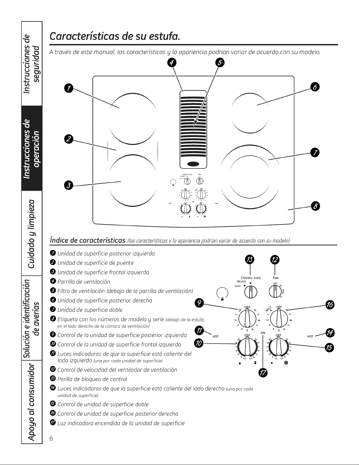
Caracteristicas de su estufa.
A travds de este manual, las caracteristicas bt la apariencia podrian variar de acuerdo con su modelo.
indite de caracteristicas (lascaracterfsticasy la aparienciapodrfanvariarde acuerdocon sumodelo)
0 Unidad de superficie posterior izquierda
Unidad de superficie de puente
0 Unidad de superficie fronta! izquierda
O Parri!la de ventilacidn
Filtro de venti!aci6n (deba]o de la parri!la de ventilaci6n)
Unidad de superficie posterior derecha
Unidad de superficie doble
Etiqueta con los nOmems de mode!o y serie (debajodelaestufa,
en el lado derecho de la cdmara de ventilaci6n)
O Contro! de la unidad de superficie posterior izquierda
0 Contro! de la unidad de superficie frontal izquierda @
0 Luces indicadoras de que la superficie estd caliente de!
lado izquierdo (unapor cada unidad de superficie)
Contro! de ve!ocidad de! ventilador de ventilaci6n
Peri!la de b!oqueo de contro!
CONTROL LOCK
UNLOCK
o
LOCK O@
Luces indicadoras de que /a superficie estd ca/iente de!/ado derecho (unapotcada
unidad de superficie)
Contro! de unidad de superficie doble
Contro! de unidad de superficie posterior derecha
Luz indicadora encendida de la unidad de superficie
FAN
OFF /',/
• ®

C6mo usar ias unidades de superficie.
Unidades de superficie radiantes
F
,_ _,_ _ Elcontrolde launidaddesuperficie
,, YFI ' I_ q _ radiantepuedecolocarseencualquierlugar
_ entreLO(Bajo)gHl(Alto]paraunnOmerode
_"__, I i ] seecconesde caentamento mtado Cone
@_ _ }/_. interruptorinfinitoelembobinadohaceciclo
#_ " entreencenddog apagadoparamantener
controlde suselecci6n.
Parahervirliquidos,useunaalia o sart_nqua
HOT ON
Cerci6resede girar el bot6nde control
a apagado(OFF)cuandoterminede
cocinar.
tengatapa.
Elbot6nde controldebeempujarsehaciaabajo
gmovidodesdela posici6nOFF(Apagado).
Cuandolosbotonesde controlest6nen
cualquierposici6nqueno seaAPAGADO,
puedenmoversesinpresionarlos.
Cerci6resede girarel bot6nde controla la
posici6napagadocuandoterminedecocinar.
Ustedsentir6unclic en la posici6nOFF.
Laluzindicadorade la unidaddesuperficie
brillar6cuandocualquiemde las unidadesde
superficieest@nencendidasON(Encendido].
NOTA:LoluzindicodorodeON(Encendido)de
unidoddesuperficiepodriobrillorentrelos
posicionesLO(Bojo)g OFF(Encendido)del
controldesuperficie,peronohag energfo
eldctricollegondoo losunidodesdesuperficie.
Lastemperaturasdelaestufaaumentan
con elnOmerode unidadesde superficie
queest@nencendidas.Con] 6/4 unidades
encendidas,lastemperaturasde superficie
sonaltas,asiqua tengacuidadocuando
toquela estufa.
LaslucesindicadorasdeHOTSURFACE
(Superficiecaliente)brillar6ncuando
elelementoradianteest@encendido,g
permanecer6nencendidashastaquala
superficieseenfriea aproximadamente
150° F.
NOTA:
Laslucesindicadorasdesupefficieseencienden
instantdneamenteypermanecenencendidasa(ln
cuandola unidaddesuperficieseaapagada.
Laslucesbrillanconmuchaintensidadhastaque
la unidadseenfrfaa aproximadamente150° #
Aseg(lresede apagarlaperilladecontrolcuando
terminede cocinar
Nuncacocinedirectamentesabreel
vidrio. Siempreuseplazasde cocina.
Siemprecoloquelasart6nen el centro
de la unidadde superficieen la que est_
cocinando.
No deslicesartenesencimade la
superficiede la estufaporqueesto
podriarasgu_arel vidrio. Elvidrio
esresistente,pero no esa pruebade
rasgu_os.
Acercu de lus unidudes de superficie radiuntes...
Laestufa radiante tiene unidades calentadoras
pardebajode una superficiesuavedevidrio.
NOTA: Unolorligemesnormalcuandounaestufa
nuevaesusadaporprimeravez.Estoescausadopord
calentamientode/aspartesnuevasy losmaterialesde
aislamientoy desaparecerdencortotiempo.
NOTA:Enalgunosmodelosdeestufasconvidrios
concoloresligems,esnormalquelazonadecocinado
cambiedecolorcuandosecalientaocuandoseenfrfa.
Estoestemporalydesaparecerdconformeel vidriose
enfrfaa temperaturaambiente.
Launidaddesuperficiehar(icicloentre
encendidog apagadoparamantenerlos
controlesdesu selecci6n.
Lasmanchasdeagua(dep6sitosde minera/es)se
remuevenusandounacremade limpiezao vinagre
blancopure.
Elusadelimpbdordeventanaspodrfadejaruna
pelfculairidiscentesabrelaestufa.Lacremade
limpiezaremoverdestadecoloraci6n.
Noalmaceneartfculospesadossobrelaestufa.
Sisecaensobrelaestufa,podrfandafiarla.
Nouselasuperficiecomotabladecorte.
Essegurocolocarunapiezadecocinacaliente
delhorno o dela superficiesabrela superficie
devidriocuandola superficieest(ifria.
AOndespu@sdeque lasunidadesde superficie
son apagadas,laestufadevidrioretiene
suficientecalorpara continuarcocinando.Para
evitarcocinarexcesivamente,remuevalas
sartenesdelasunidadesde superficiecuando
lacomidasehagacocinado.Evitecolocar
ningOnobjetosabrelasuperficiehastaqua
se hagaenfriadocompletamente.
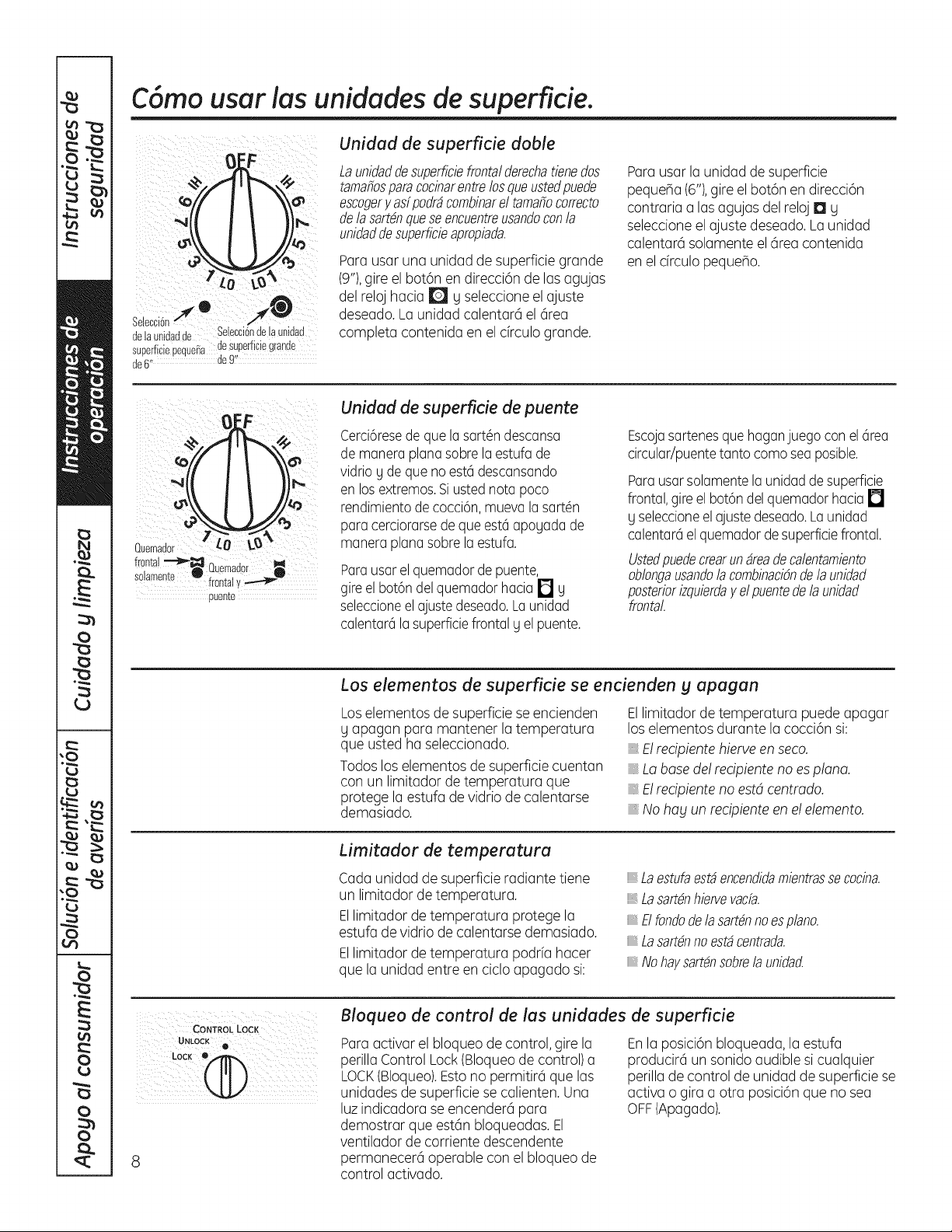
C6mo usar ias unidades de superficie.
€
delaunidadde Selecci6ndelaunidad
superficiepequemiadesuperfic!eg[ande
de6,, de9!'
Unidad de superficie doble
Launidaddesuperficiefrontaldemchatienedos
tamafiosparacocinarentrelosqueustedpuede
escogery asfpodrdcombinarel tamaMcorrecto
dela sartdnqueseencuentmusandoconla
unidaddesuperficieapropiada.
Para usar una unidad de superficie grande
(9"),gire el bot6n en direcci6n de los agujas
del reloj hacia Ir@Jg seleccione el ajuste
deseado.La unidad calentarci el 6rea
completa contenida en el cfrculo grande.
Para usar Io unidad de superficie
peque_a (6"),gire el bot6n en direcci6n
contraria alas agujas del reloj I:1 g
seleccione el ajuste deseado. Launidad
calentarci solamente el cirea contenida
en el drculo pequeho.
Quemador £0 %_
frontal"-"1_-_ r, i
uuemaaor
solamente f it l
rol a y
puente
Unidad de superficie de puente
Cerci6resede que lasart6n descansa
de manera planasabre laestufa de
vidrio gde que noest(_descansando
en losextremos.Si ustednora poco
rendimientode cocci6n,muevala sart6n
para cerciorarsedeque est(_apogadade
manera planasabre la estufa.
Parausar elquemador depuente,
gireel bot6n del quemador hacia 17 y
seleccioneelajuste deseado.La unidad
calentarcilasuperficiefrontal g el puente.
Escojasartenesque haganjuego con elcirea
circular/puentetanto coma sea posible.
Parausarsolamentela unidadde superficie
frontal,gire el bot6n delquemador hacia []
gseleccioneel ajustedeseado.La unidad
calentarciel quemadorde superficiefrontal.
Listedpuedecrearundreadecalentamiento
oblongausandolacombinacidndela unidad
posteriorizquierday el puentedela unidad
frontal
Los elementos de superficie se encienden y apagan
Loselementos de superficie se encienden
y apagan para mantener la temperatura
que usted ha seleccionado.
Todos los elementos de superficie cuentan
con un limitador de temperatura que
protege la estufa de vidrio de calentarse
demasiado.
Ellimitador de temperatura puede apagar
los elementos durante la cocci6n si:
E!recipiente hierve en seco.
Labase de! recipienteno esplana.
E!recipiente no estd centmdo.
., No hag un recipiente en e!elemento.
Limitador de temperatura
Cada unidad de superficie radiante tiene
un limitador de temperatura.
Ellimitador de temperatura protege la
estufa de vidrio de calentarse demasiado.
Ellimitador de temperatura podrfa hacer
que la unidad entre en ciclo apagado si:
Laestufaestdencendidamientrassecocina.
Lasart#nhiervevacfa.
Elfondodela sartdnnoespiano.
Lasartdnnoestdcentrada.
Nohaysartdnsobrela unidacZ
CoNTRoLLock
LOCK ®@
Bloqueo de control de las unidades de superficie
Para activar el bloqueo de control, gire la
perilla Control Lock(Bloqueode control) a
LOCK(Bloqueo).Estono permitirci que las
unidades de superficie se calienten. Una
luz indicadora se encendercipara
demostrar que estcin bloqueadas. El
ventilador de corriente descendente
permanecerci operable con el bloqueo de
control activado.
Enla posici6n bloqueada, la estufa
producirci un sonido audible si cualquier
perilla de control de unidad de superficie se
activa o gira a otra posici6n que no sea
OFF(Apagado).
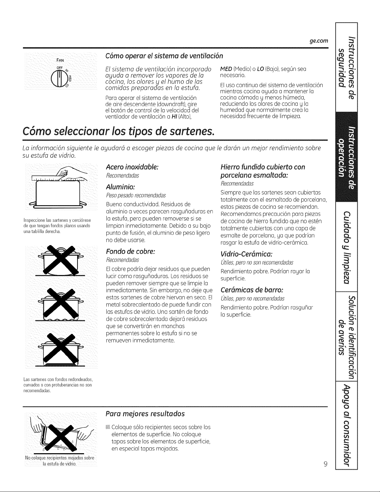
ge.com
C6mo operar el sistema de ventilaci6n
OFF
i_ii _iiiiiiiii _i_iiiiiiiiiiiiii
El sistema de ventilaci6n incorporado
ayuda a remover los vapores de la
cocina, los olores_ el humo de las
comidas preparadas en la estufa.
Paraoperar el sistema de ventilaci6n
de aire descendente (downdraft),gire
el bot6n de control de la velocidad del
ventilador de ventilaci6n a HI (Alto},
MED (Media)o LO(Bojo),segOnsea
necesorio.
Elusa continua del sistema de ventilaci6n
mientras cocina aguda a mantener la
cocina c6moda g menos hOmeda,
reduciendo los olores de cocina g la
humedad que normalmente crea la
necesidadfrecuente de limpieza.
C6rno seleccionur los tipos de surtenes.
La informaci6n siguiente le ayudard a escoger piezas de cocina que le dardn un mejor rendimiento sabre
su estufa de vidrio.
Inspeccionelas sartenesy cerci6rese
de quetenganfondos pianosusando
unatablilla derecha.
Acero inoxiduble:
Recomendadas
Aluminio:
Pesopesadorecomendadas
Buena conductividad. Residuosde
aluminio a veces parecen rasguhaduras en
la estufa, pero pueden removerse si se
limpian inmediatamente. Debido a su bajo
punto de fusi6n, el aluminio de peso ligero
no debe usarse.
Fondo de cobre:
flecomendadas
Elcobre podrfa dejar residuosque pueden
lucir coma rasguhaduras. Los residuosse
pueden remover siempre que se limpie la
inmediatamente. Sin embargo, no deje que
estas sartenes de cobre hiervan en seco. El
metal sobrecalentado de puede fundir con
las estufas de vidrio.Una sart6n de fondo
de cobre sobrecalentada dejar6 residuos
que se convertir6n en manchas
permanentes sabre la estufa si no se
remueven inmediatamente.
Hierro fundido cubierto con
porcelana esmaltada:
Recomendadas
Siempre que las sartenes sean cubiertas
totalmente con el esmaltado de porcelana,
estas piezasde cocina se recomiendan.
Recomendamos precauci6n para piezas
de cocina de hierro fundido que no est6n
totalmente cubiertas con una capa de
esmalte de porcelana, ya que podrfan
rasgar la estufa de vidrio-cer6mica.
Vidrio-Cer(_micu:
t)tiles,peronosonrecomendadas
Rendimiento pobre. Podrfan rayar la
superficie.
Cer_micus de burro:
t)tiles,peronorecomendadas
Rendimiento pobre. Podrfan rasguhar
la superficie.
Lassartenesconfondos redondeados,
curvadoso conprotuberanciasno son
recomendadas.
No coloquerecipientesmojadossabre
la estufa devidrio.
Para mejores resultados
. Coloque s61orecipientes secos sabre los
elementos de superficie.No coloque
tapas sabre los elementos de superficie,
en especialtapas mojadas.
9
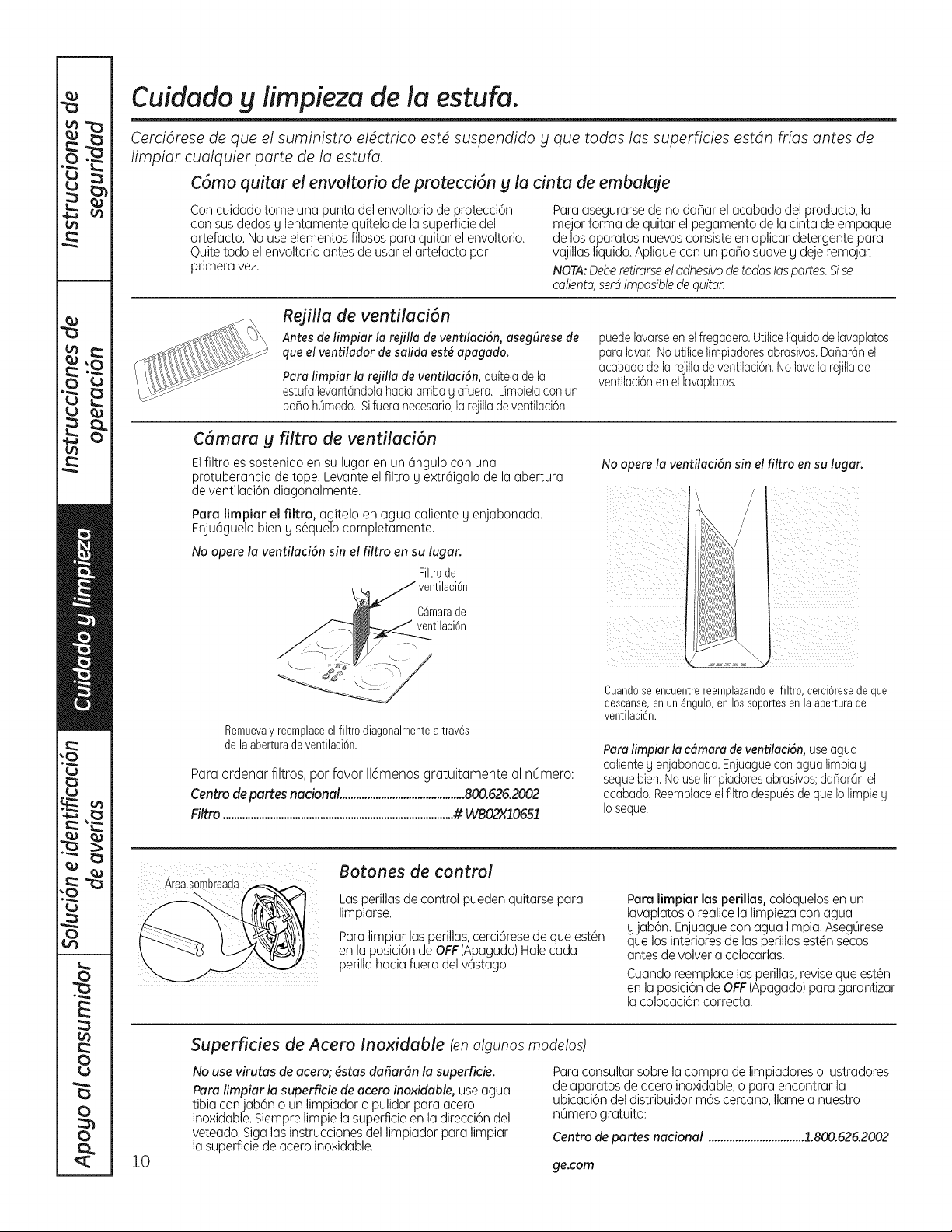
Cuidado g iimpieza de la estufa.
Cerci6rese de que el suministro el4ctrico estd suspendido _t que todas las superficies estdn frfas antes de
Iimpiar cualquier parte de la estufa.
C6mo quitar el envoltorio de protecci6n g la cinta de embalaje
Con cuidado tome una punta del envoltorio de protecci6n
con sus dedos g lentamente quitelo de la superficie del
artefacto. No use elementos filosos para quitar el envoltorio.
Quite todo el envoltorio antes de usar el artefacto por
primera vez.
Para asegurarse de no daBar el acabado del producto, la
mejor forma de quitar el pegamento de la cinta de empaque
de los aparatos nuevos consiste en aplicar detergente para
vajillas liquido. Aplique con un paBo suave g deje remojar.
NOTA:Deberedrarseeladhesivode todas laspartes.Sise
calienta,serd imposiblede quitar
Rejilla de ventilaci6n
Antes de limpiar la rejilla de ventilaci6n, asegf_rese de
que el ventilador de salida est_ apagado.
Para limpiar la rejilla de ventilaci6n, quitelade la
estufa levant6ndotahaciaarribag afuera. Limpielacon un
pa_oh0medo. Sifueranecesario,larejitladeventilaci6n
puedelavarseen el fregadero.Utiticeliquidodelavaplatos
para lavar.No utiticelimpiadoresabrasivos.Da_ar6nel
acabadode larejillade ventilaci6n.Nolavela rejiltade
ventilaci6nen el lavaplatos.
C6mara g filtro de ventilaci6n
Elfiltro es sostenido en su lugar en un 6ngulo con uno
protuberancia de tope. Levante el filtro g extr6igalo de la abertura
de ventilaci6n diagonalmente.
Para limpiar el filtro, agitelo en agua caliente g enjabonada.
Enju6guelo bien g s@quelocompletamente.
No opere la ventilaci6n sin el filtro en su lugar.
Filtro de
ventilaci6n
C_marade
ventilaci6n
No opere la ventilaci6n sin el
i ii i
filtro en su lugar.
i _ ii i
i kfi_ _iI_ ii_
i iii/i_/ _ iilk
Remuevay reemplaceel filtro diagonalmentea trav_s
de la aberturade ventilaci6n.
Para ordenar filtros, pot favor 116menosgratuitamente al nOmero:
Centro de partes nadona! .............................................800.626.2002
Fi!tro ...................................................................................# WBO2X!0651
Cuandose encuentrereemplazandoel filtro, cerci6resede que
descanse,enun _ngulo, en los soportesen la abertura de
ventilaci6n.
Paraiimpiar la c6mara de ventilaci6n, use agua
calienteg enjabonada.Enjuaguecon agua limpia g
sequebien.Nouse limpiadoresabrasivos;danar6net
acabado.Reemplaceelfittro despu6sde que Io limpieg
Ioseque.
Area sombreada
Botones de control
Las perillas de control pueden quitarse para
limpiarse.
Para limpiar las perillas,cerci6rese de que est@n
en la posici6n de OFF(Apagado) Hale cada
perilla hacia fuera del v6stago.
Paralimpiar lasperillas,col6quelosen un
lavaplatoso realicelalimpiezaconagua
yjab6n. Enjuagueconagua limpia.Aseg0rese
quelosinterioresde lasperillasest@nsecos
antesdevolvera colocarlas.
Cuandoreemplacelasperillas,revisequeest@n
enla posici6nde OFF(Apagado)paragarantizar
lacolocaci6ncorrecta.
10
Superficies de Acero Inoxidable (enalgunos mode!os)
No use virutas de acero; #stas dafiar6n la superficie.
Peru !impiar !a superficie de acero inoxidable, use agua
tibia conjab6n o un limpiador o pulidor para acero
inoxidable. Siempre limpie la superficie en la direcci6n del
veteado. Siga las instrucciones del limpiador para limpiar
la superficie de acero inoxidable.
Paraconsultarsobrela comprade limpiadoreso lustradores
deaparatosdeaceroinoxidable,o paraencontrarla
ubicaci6ndeldistribuidorm6scercano,Ilamea nuestro
n0merogratuito:
Centro de partes nacional ................................1.800.626.2002
ge.com
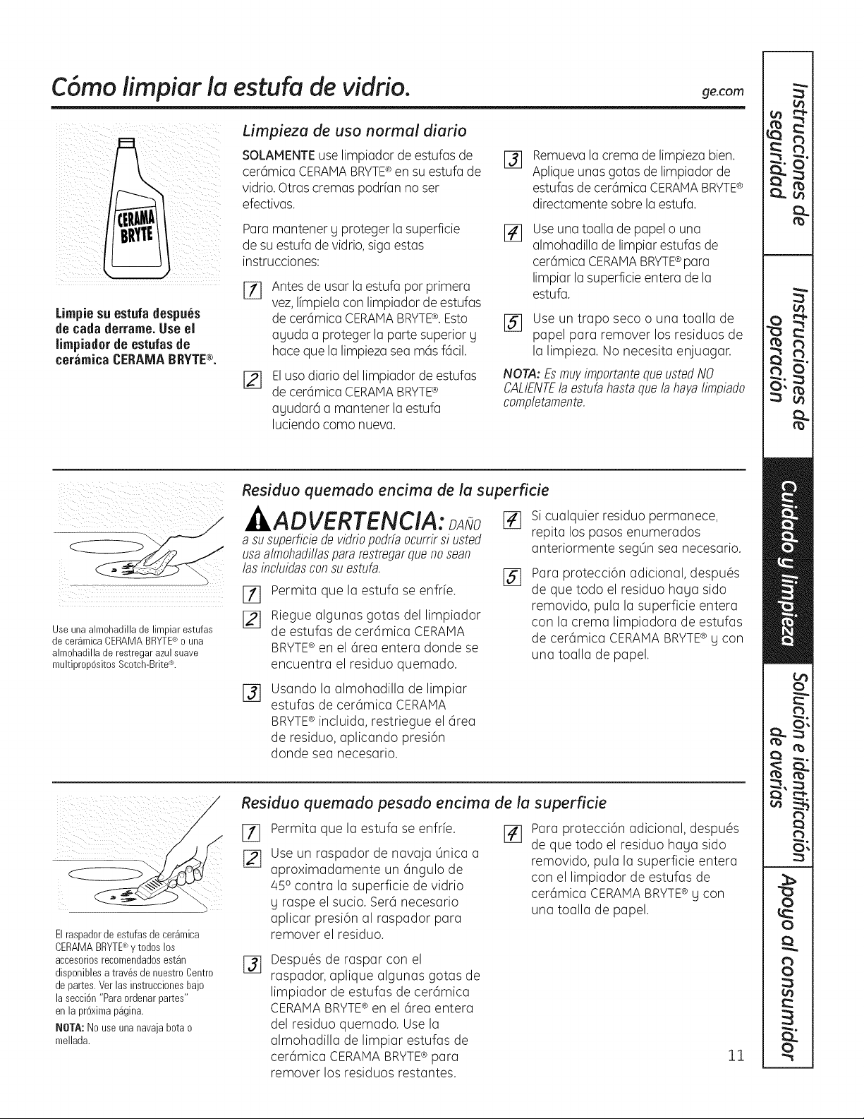
C6mo iimpiar ia estufa de vidfio, ge.com
Limpiesu estufadespues
de cada derrame.Useel
limpiadorde estufasde
ceramica CERAMABRYTE®.
Limpieza de usa normal diario
SOLAMENTEuse limpiador de estufas de
cer6mica CERAMABRYTE®en su estufa de
vidrio. Otras cremas podrfan no ser
efectivas.
Para mantener g proteger la superficie
de su estufa de vidrio,siga estas
instrucciones:
%
[]
Antes de usar la estufa por primera
vez, Ifmpiela con limpiador de estufas
de cer6mica CERAMABRYTE®.Esto
aguda a proteger la parte superior g
hace que la limpieza sea m6s f6cil.
Eluso diario del limpiador de estufas
de cer6mica CERAMABRYTE®
agudar6 a mantener la estufa
luciendo como nueva.
%
Remuevala crema de limpieza bien.
Aplique unas gotas de limpiador de
estufas de cer6mica CERAMABRYTE®
directamente sobre la estufa.
Useuna toalla de papel o una
almohadilla de limpiar estufas de
cer6mica CERAMABRYTE¢para
Iimpiar la superficie entera de la
estufa.
[_ Use un trapo seco o una toalla de
papel para remover los residuos de
la limpieza. No necesita enjuagar.
NOTA: £s mw importantequeusted NO
CALIENTEla estufahasta quela hayaIimpiado
completamente.
\
)
Use una almohadilla de limpiar estufas
de cer_mica CERAMA BRYTE_ o una
almohadilla de restregar azul suave
multiprop6sitos Scotch-Brite_L
Residuo quemado encima de la superficie
ADVERTENCIA:
a su superficiede vidriopodrfaocurrirsi usted
usaalrnohadillaspara restregarquenosean
las incluidasconsu estufa.
Permita que la estufa se enfrfe.
Riegue algunas gotas del limpiador
de estufas de cer6mica CERAMA
BRYTE® en el 6rea entera donde se
encuentra el residuo quemado.
[]
%
Si cualquier residuo permanece,
repita los pasos enumerados
anteriormente seg0n sea necesario.
Para protecci6n adicional, despu6s
de que todo el residuo haga sido
removido, pula la superficie entera
con la crema limpiadora de estufas
de cer6mica CERAMABRYTE¢ g con
una toalla de papel.
%
Usando la almohadilla de limpiar
estufas de cer6mica CERAMA
BRYTE® incluida, restriegue el 6rea
de residuo, aplicando presi6n
donde sea necesario.
Elraspadorde estufasde cer_mica
CERAMABRYTE®y todos los
accesoriosrecomendadosest_n
disponiblesa trav6s de nuestroCentro
de partes.Ver los instruccionesbajo
la secci6n"Paraordenarpartes"
en la pr6ximap_gina.
BIOTA:No use unanavaja botao
mellada.
Residuo quemado pesado encima de la superficie
[_ Permita que la estufa se enfrfe. J_
Use un raspador de navaja 0nica a
aproximadamente un 6ngulo de
45o contra la superficie de vidrio
g raspe el sucio. Ser6 necesario
aplicar presi6n al raspador para
remover el residuo.
Para protecci6n adicional, despu6s
de que todo el residuo haga sido
removido, pula la superficie entera
con el limpiador de estufas de
cer6mica CERAMABRYTE¢ g con
una toalla de papel.
%
Despu6s de raspar con el
raspador, aplique algunas gotas de
limpiador de estufas de cer6mica
CERAMA BRYTE® en el 6rea entera
del residuo quemado. Use la
almohadilla de limpiar estufas de
cer6mica CERAMA BRYTE® para
remover los residuos restantes.
11
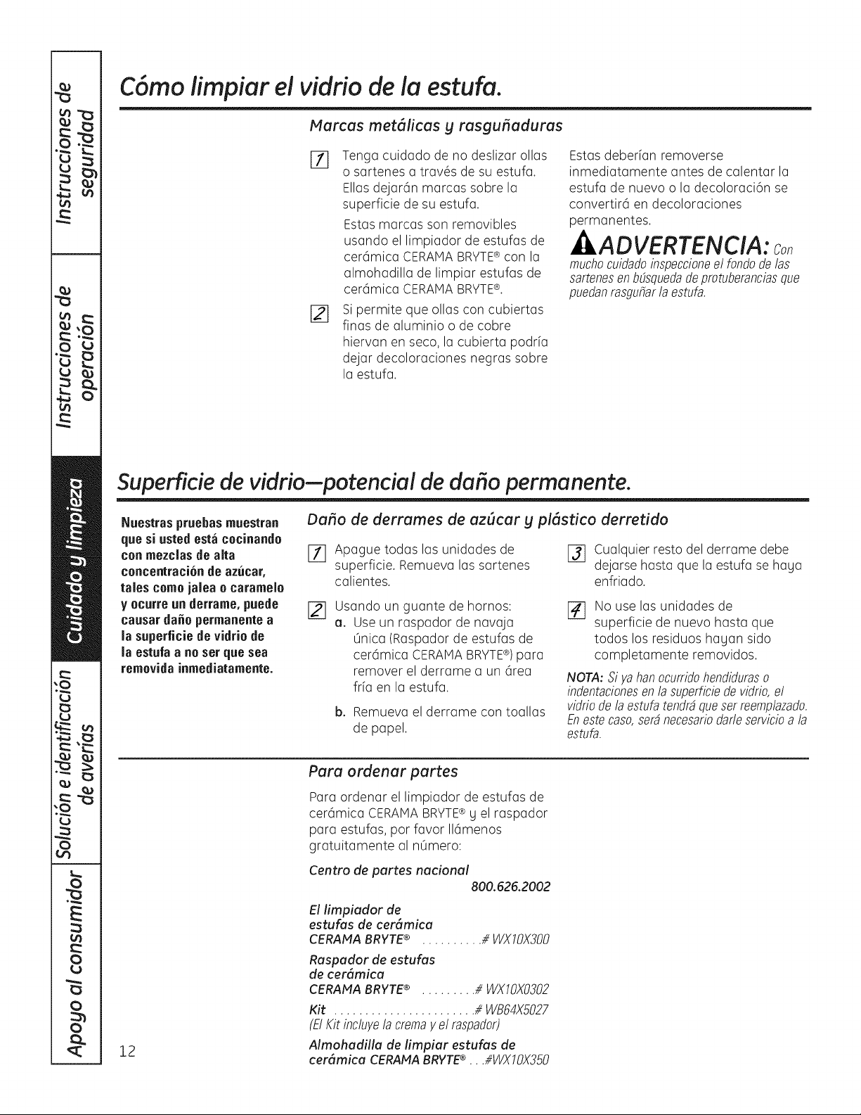
C6mo iimpiar el vidfio de la estufa.
Marcas met61icas g rasgu_aduras
_7] Tenga cuidado de no deslizar alias
o sartenes (] tr(]v@s de su estufa.
Elias dejar6n m(]rc(]s sabre I(]
superficie de su estuf(].
Estas marcas son removibles
usando el limpiador de estufas de
cer6mic(] CERAMA BRYTE® con I(]
(]lmoh(]dill(] de limpi(]r estuf(]s de
cer6mic(] CERAMA BRYTE¢.
[_] Si permite que oil(is con cubiert(]s
fin(is de (]luminia o de cobre
hierv(]n en seco, I(] cubiert(] podr[(]
dej(]r decolor(]ciones negr(]s sabre
I(] estuf(].
Estas deberf(]n removerse
inmediat(]mente antes de c(]lent(]r la
estuf(] de nuevo o I(] decolor(]ci6n se
convertir6 en decolor(]ciones
perm(]nentes.
-tI ADVERTENCIA:
muchocuidadoinspeccioneel fondode las
sartenesen bE_squedade protuberanciasque
puedanrasgufiarla estufa.
Superficie de vidrio-potencial de dafio permanente.
Nuestras pruebasmuestran
quesi ustedesta cecinande
conmezclas de alta
cencentraci6nde azucar,
tales come jalea e caramele
y ecurre un derrame, puede
causarda_e permanentea
la superficie de vidrie de
la estufa a ne set que sea
remevidainmediatamente.
Da_o de derrames de azScar g pl6stico derretido
[_ Ap(]gue tad(is I(]s unid(]des de
superficie. Remuev(] I(]s s(]rtenes
c(]lientes.
[_ Cualquier resto del derrame debe
dejarse hasta que la estufa se haga
enfriado.
[] Us(]ndo un gu(]nte de hornos: [_
a. Use un r(]sp(]dor de nav(]j(]
0nica (Raspador de estufas de
cer6mic(] CERAMA BRYTE®) par(]
remover el derr(]me (] un 6re(]
frf(] en la estuf(].
b. Remuev(] el derr(]me con to(ill(is
de papel.
No use las unidades de
superficie de nuevo hasta que
todos los residuos hagan sido
complet(]mente removidos.
NOTA: Siya han ocurridohendiduraso
indentacionesenla superficiede vidrio,el
vidriode la estufa tendr4queser reemplazado.
Enestecaso,ser4necesariodafleservicioa la
estufa.
12
Para ordenar partes
P(]r(] arden(jr el limpiador de estuf(]s de
cer6mic(] CERAHABRYTE® g el r(]sp(]dor
p(]r(] estuf(]s, par f(]vor 116menos
gr(]tuit(]mente (]1n0mero:
Centre de partes nacional
800.626.2002
El limpiador de
estufas de cer#mica
CERAMA BRYTE® .......... _ WXIOX300
Raspador de estufas
de cer6mica
CERANA BRYTE® ......... # WXIOX0302
Kit ....................... //WB64X5027
(El Kit inclwe la crema y el raspador)
Almohadilla de limpiar estufas de
cer6mica CERANA BRYTE® . . .i/WX10X350
instru"
de instalaci6n
Estufa radiante de
ventilaci6n descendente
S)tiene alguna pregunta, Ilame al 800.GE.CARES(800.432.2737)o visite nuestro sitio en la Web: ge.com J
ANTES DE COMENZAR
Lea estas instrucdones completa y
cuidadosamente.
• IMPORTANTE - Guardeestas
instrucciones pare ser usadas par el inspector
el6ctrico.
•IMPORTANTE - Observetodoslos
c6digos g ordenanzas aplicables.
• Nota al instalador - Cerci6rese de dejar estas
instrucciones con el Consumidor.
• Nota al consumidor - Guarde estas
instrucciones pure referencia futura.
• A no ser que usted sea una persona mug bien
entrenada en la instalaci6n de este producto,
busque la aguda de un instalador profesional.
• La instalaci6n apropiada es la responsabilidad
del instalador.
• Si este producto falla par una instalaci6n
inapropiada, la Garantia no cubrir6 este
producto.
ADVERTENCIA - Antes de comenzar la
instalaci6n, desconecte el interruptor de
suministro el6ctrico en el panel de servicio g
cierre el mecanismo de seguridad para evitar
que alguien Io conecte accidentalmente.
Cuando no exista un dispositivo de cierre de
seguridad, amarre un aviso visible, coma una
etiqueta al panel de servicio hacienda la
advertencia.
INSTRUCCIONES IMPORTANTES DE
SEGURIDAD
ADVERTENCIA - PARAREDUCIREL
RIESGO DE INCENDIOS, DESCARGAS
ELI_CTRICASO LESIONES PERSONALES,
OBSERVE LO SIGUIENTE:
r_ El trabajo de instalaci6n g el alambrado
el6ctrico debe hacerlo una persona(s)
calificada conforme a todos los c6digos
g est6ndares aplicables, inclugendo una
construcci6n aprobada par el inspector de
incendios.
@ Suficiente aire es necesario para una
combusti6n apropiada g para deshacerse de
los gases a trav6s de una salida de humo
(chimenea) de equipos que queman
combustibles para prevenir retroalimentaci6n.
Siga las recomendaciones del fabricante
del equipo de calentamiento g los est6ndares
de seguridad tales coma los publicados par la
Asociaci6n nacional de protecci6n de
incendios (NFPA), g la Sociedad americana de
ingenieros de calefacci6n, acondicionadores
de aire g refrigeraci6n (ASHRAE), g los c6digos
de las autoridades locales.
[E]
Cuando se encuentre cortando o taladrando
en la pared o en el techo, no dane los
alambrados el6ctricos u otras utilidades
escondidas.
r_ Los ventiladores conectados a conductos
deben siempre estar ventilados hacia el
exterior.
,,La unidad debe estar conectada a tierra
apropiadamente.
ADVERTENCIA - PARAREDUCIREL
RIESGO DE INCENDIOS, SOLAMENTE USE
CONDUCTOS M ET/i_LICOS.
13
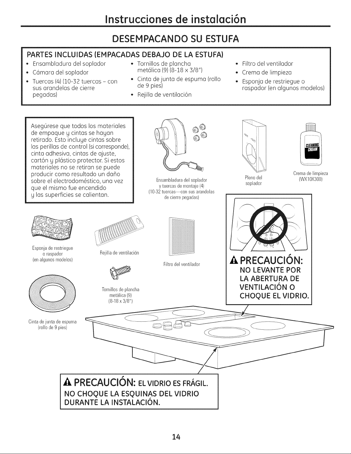
Instruccionesde instalaci6n
DESEMPACANDO SU ESTUFA
PARTES INCLUIDAS (EMPACADAS DEBAJO DE LA ESTUFA}
• Ensambladura del soplador
• C6mara del soplador
• Tuercas (4)(10-32 tuercas - con
sus arandelas de cierre
pegadas)
Tornillos de plancha
met61ica (9)(8-18 x 3/8")
• Cinta de junta de espuma (rollo
de 9 pies)
• Rejilla de ventilaci6n
• Filtro del ventilador
• Crema de limpieza
• Esponja de restriegue o
raspador (en algunos modelos)
AsegOrese que todos los materiales
de empaque g cintas se hagan
retirado. Esto incluge cintas sobre
las perillas de control (si corresponde),
cinta adhesiva, cintas de ajuste,
cart6n g pl6stico protector. Si estos
materiales no se retiran se puede
producir como resultado un da_o
sobre el electrodom6stico, una vez
que el mismo fue encendido
g las superficies se calientan.
Esponja de restriegue
o raspador
(en algunos modelos)
Rejilla de ventilaci6n
Tornillosdeplancha
met41ica(9)
(8-18x 3/8")
Ensambladuradel soplador
y tuercasde montaje(4)
(10-32tuercas--con susarandelas
de cierre pegadas)
I
Filtro del ventilador
Cremade limpieza
Plenodel (WXIOX300)
soplador
PRECAUCION:
NO LEVANTE POR
LA ABERTURA DE
VENTILACI6N 0
CHOQUE EL VIDRIOo
PRECAUCION:EL VIDRIO ES FRAGIL.
NO CHOQ)UE LA ESQ)UINAS DEL VIDRIO
DURANTE LA INSTALACION.
14
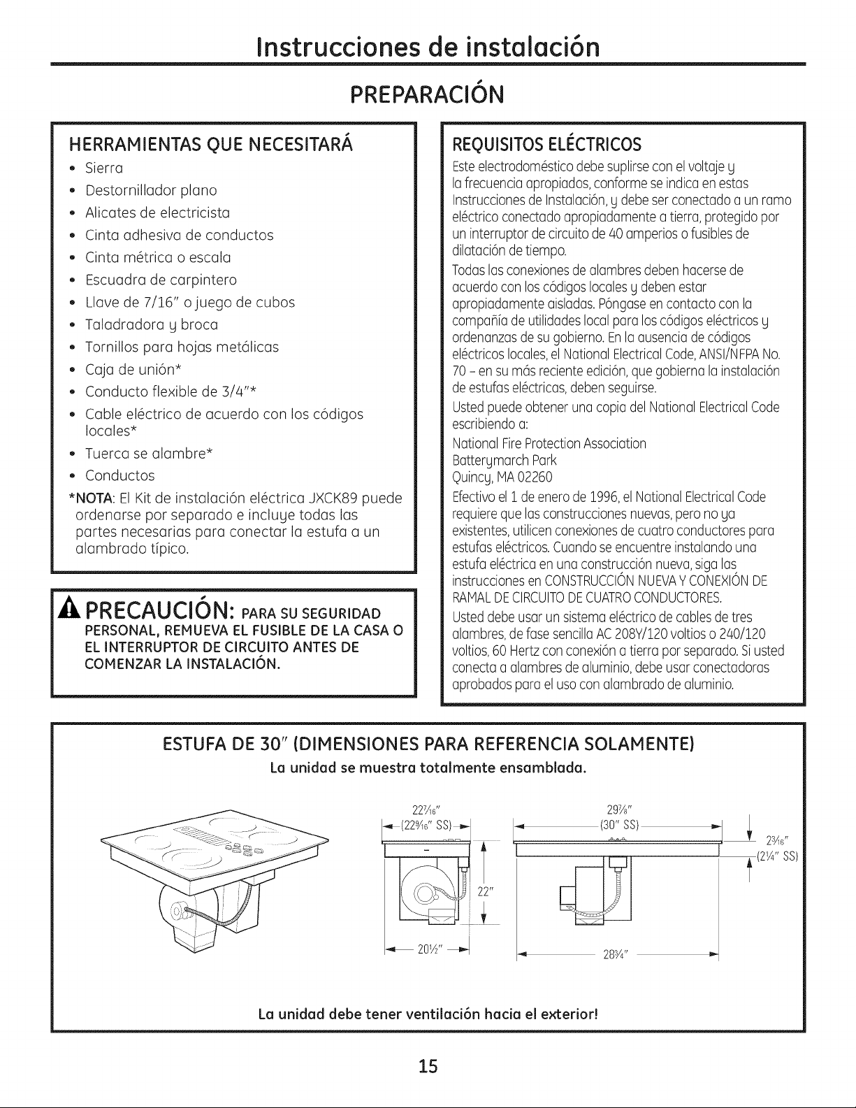
Instruccionesde instalaci6n
PREPARACION
HERRAMIENTAS QUE NECESITAR#,
• Sierra
• Destornillador piano
Alicates de electricista
Cinta adhesiva de conductos
Cinta m6trica o escala
Escuadra de carpintero
Llave de 7/].6" ojuego de cubos
Taladradora g broca
Tornillos para hojas met61icas
caja de uni6n*
• Conducto flexible de 3/4"*
• Cable el6ctrico de acuerdo con los c6digos
locales*
Tuerca se alambre*
• Conductos
• NOTA: El Kit de instalaci6n el6ctrica JXCK89 puede
ordenarse por separado e incluge todas las
partes necesarias para conectar la estufa a un
alambrado tipico.
PRECAUCI6N: PARA SU SEGURIDAD
PERSONAL, REMUEVA EL FUSIBLE DE LA CASA O
EL INTERRUPTOR DE CIRCUITO ANTES DE
COMENZAR LA INSTALACI6N.
REOUISITOSELI_CTRICOS
Esteelectrodom6stico debe suplirsecon el voltaje g
la frecuencia apropiados,conforme se indica en estas
Instruccionesde Instalaci6n, y debe ser conectado a un ramo
el6ctrico conectado apropiadamente a tierra, protegido pot
un interruptor de circuito de 40 amperios o fusibles de
dilataci6n detiempo.
Todaslas conexiones de alambres deben hacersede
acuerdo con los c6digos locales y deben estar
apropiadamente aisladas. P6ngaseen contacto con la
compaflfa de utilidadeslocal para los c6digos el6ctricos g
ordenanzas de su gobierno. Enla ausencia de c6digos
el6ctricos locales,el National ElectricalCode,ANSIiNFPANo.
70- en su m6s reciente edici6n, que gobierna la instalaci6n
de estufas el6ctricas, deben seguirse.
Ustedpuede obtener una copia del National ElectricalCode
escribiendo a:
National FireProtection Association
Battergmarch Park
q)uincg,MA 02260
Efectivoel 1 de enero de 1996,el National ElectricalCode
requiere que las construcciones nuevas, pero no ga
existentes,utilicenconexiones de cuatro conductores para
estufas el6ctricos.Cuando se encuentre instalando una
estufa el6ctrica en una construcci6n nueva, siga las
instrucciones en CONSTRUCCIONNUEVAYCONEXIONDE
RAMALDECIRCUITODECUATROCONDUCTORES.
Usteddebe usar un sistema el6ctrico de cables de tres
alambres, de fase sencillaAC208Y/120 voltios o 240/120
voltios,60 Hertz con conexi6n a tierra pot separado. Siusted
conecta a alambres de aluminio, debe usar conectadoras
aprobados para el usa con alambrado de aluminio.
ESTUFA DE 30" (DIMENSIONES PARA REFERENCIA SOLAMENTE)
LQ unidad se muestra totalmente ensamblada.
227Ad'
[-,,_(229Ad' SS!_,--J
L--
297A,,
(30"SS)
I
28¾"
La unidad debe tener ventilaci6n hacia el exterior!
15
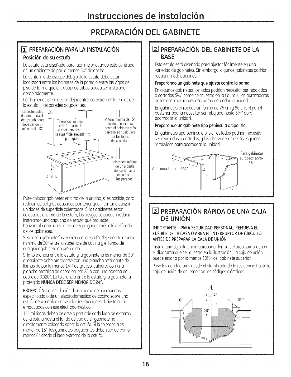
Instruccionesde instalaci6n
PREPARACI6N DEL GABINETE
m PREPARACI6N PARA LA INSTALACI6N
Posici6ndesuestufa
Laestufaestadisehadaparalucir mejorcuando est6centrada
en un gabinetede par Io menosSO"de ancho.
Laventanilladeescapedebajo de la estufadebeestar
Iocalizadaentre losbajantesde la paredo entre lasvigasdel
pisode forma queel trabajo de tubaspueda ser instalado
apropiadamente.
ParIo menos6" sedebendejar entre losextremoslateralesde
laestufa y lasparedesadyacentes.
LaprofundidadF,L.
del_rea elevada / I I J
de losgabinetesI/-IIToleranciaminima I Alturaminimade 15"
debeser de un /11 de 30" a partir de I desde la encimera
m_ximode 13" |11 la encimerahasta I hasta el gabinete m_s
||1 la superficie elevada -_ cercanoen cualquiera
protegida, dejloslados
............[ delaunidad.
ST
Toleranciaminima
de 6"a partir
delcartehasta
1W'min. losladosde
lasparedes.
Evitecolocargabinetesencimade la unidad,si es posible,para
reducirlospeligroscausadospartener queintentar alcanzar
unidadesdesuperficiecalentadas.Silosgabinetesestan
colocadosencima dela estufa,losriesgossepueden reducir
instalandounacapuchade estufaque proyecte
horizontalmenteun minimade 5pulgadasmasalia delfondo
de losgabinetes.
Sise usangabineteriasencimade laestufa,deje una tolerancia
minimade 30" entrela superficiede cocinaY el fondo de
cualquiergabineteno protegido.
Sila tolerancia entre laestufa Y la gabineteriaesmenor de 30",
el gabinetedebe protegersecon una plancharetardante de
llamasde par Iomenos 1/4" degrueso,cubierta con una
planchametalicadeacero calibre28o con una panchade
cobre de0D20". Latoleranciaentrela estufaYla gabineteria
protegidaNUNCADEBESERMENORDE24".
E×CEPCI6N:Loinstulaci6nde un homo de microondas
especificadoo de unelectrodom6sticodecocina sabreuno
estufa debeconformarsealas instruccionesdeinstalaci6n
empocadascon eseelectrodom6stico.
15" minimasdebendejarsea partir de cada lado de extremo
de la estufahasta el rondode cuulquiergobineteno
directomentecolocadosabrelaestufa.Sila tolerancia es
menorde 15", losgubinetesadyacentesdeben serde par Io
menos6" desdeel lado extremode la estufa.
[] PREPARACI6N DEL GABINETE DE LA
BASE
Estaestufa estadise_adapara ajustarfacilmenteen una
variedadde gabinetes.Sinembargo,algunosgabinetespodrian
requerirmodificaciones.
Preparandoun gabinete que ajuste contra la pared
Enalgunosgobinetes,los ladospodrfannecesitorser rebojados
o cortados 5s/4'' coma se muestraen lafigura,y lasabrazaderas
de lasesquinasremovidaspora acomodar la unidad.
Engabineteseuropeossinforma de 75 cm y 90cm, el panel
posteriorpodrfanecesitarser rebajadohasta 5s/J' para
acomodar launidad.
Preparandoungabinete tipo peninsula o tipo isla
Engabinetestipo peninsulao isla,loslados podriannecesitar
ser rebajadoso cortados,y lasabrazaderasde lasesquinas
removidasparaacomodar la unidad.
Para gabinetes
europeos aprox.
5sA-
Aproximadamente5sA''
[_] PREPARACI6N RAPIDA DE UNA CAJA
DE UNI6N
IMPORTANTE- PARASEGURIDADPERSONAL,REMUEVAEL
FUSIBLEDELA CASA0 ABRAELINTERRUPTORDECIRCUITO
ANTESDEPREPARARLACAJADEUNION.
Instaleunacajadeuni6naprobadadentrodelareasombradaen
el diagramaquesemuestraenla ilustraci6n.Lacajadeuni6n
puedeestara parIomenoslOW'delgabinetesuperior.
Paselosconductoresdescleelalambradodela residenciahastala
cajadeuni6ndeacuerdoconlosc6digosel6ctricos.
1 6"
16

Instruccionesde instalaci6n
CORTES DE PREPARACION DEL GABINETE
I'_ PREPARANDO LA ENCIMERA
La encimera debe tener una superficie plon(]
profunda par(] acomodar I(] estufa g la
ventilaci6n. Los encimeras con un extremo
frontal rodado g "bocksplosh" puede no
proporcion(]r el 6re(] de superficie plan(]
requerid(]. Area de superficieplanade un
._querido de 25"
La tolerancio entre el frente interno del gabinete
g la porte posterior del carte en la encimer(] debe
ser de 20Y8" para poder ocomod(]r I(]
profundid(]d de I(] estuf(].
23A'' M[n.
1W' M[n.
Un @ea plana de 1/2" de ancho se requiere
alrededor del extremo de la abertura para
soportar la unidad. La unidad debe ser nivelada g
sentarse derecha en la abertura de la encimera.
Con cuidado carte la obertura de la encimera de
acuerdo con los dimensiones mostrodas en la
ilustraci6n. Cerci6rese de que la abertura es
cortada derecha, con los lados paralelos entre
s[ g con Io p(]rte posterior exoct(]mente
perpendicular (] los I(]dos.
17
[] PREPARACIONESPARALOSCONDUCTOS
NOTA:Eltmbajo de conductosDEBEtener ventilaci6nhaciael
exterior.NOVENTILEhada lasparedes,techo,esquinas,6ticoso
cualquierotro lugar cerrado.
Carteunagujeroenla pareddelgabineteo en elpisodelgabinete
seg0nseaapropiadoparasuinstalaci6n.Cerci6resedequelostubas
deescapeest6nIocalizadosentrelosbajantesde laparedo lasvigas
delpiso.
NOTA:Cuandoseencuentrecortandoo taladrandoen la paredo
enel techo,nodafielosalambradosel_ctricosuotras utilidades
escondidas.
gW'
18¾"
Ventilaci6nde la pared posterior
Ventilaci6nvertical
E] ALINEACI6NDELOSCONDUCTOSDELSOPLADOR
Engeneral,noinstamosal usade conductosflexiblesporque6ste
puedecausarseverasrestriccionesdel flujodeaire.Sinembargo,
si lasalidadelsopladorg la Iocalizaci6nen laparedo en el pisoNO
representaunproblemadealineaci6n,entoncesustedpuedeusar
conductosflexiblesMETALICOSparaadaptarla compensaci6n.Un
buencentramientosinnecesidaddeconductosflexiblesesIo
preferido.
NOTA:
, Noexcedala adaptaci6nmOximarecomendadade6".
,,Nopermitaqueelconductoflexiblese dobleoque colapse.
,,Alargueelconductoflexibletantocomaseaposibleparaevitar
lacorrugaci6ntanto comaseaposible.
6"M4ximasdesde
i i rn] _ a neacentra_11
q hastalaI[nea
I I 1/ centraJde
,,,centramiento4f
..........//
Ventilaci6nde fondo Ventilaci6ntrasera
(mequiere31/4'x 10')
Unrect6ngulode£/4" x 10"o unatronsici6ndeconductoredondo
de6" est6disponibleensutiendadesuministrosporoconstrucci6n
local.
NOTA:Lasilustmcionessonsimplementeparaqueusted
planifique.
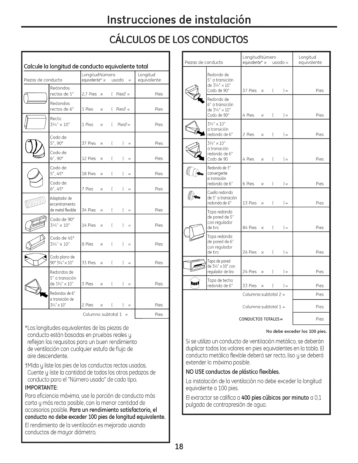
Instruccionesde instalaci6n
CALCULOS DE LOS CONDUCTOS
CQIcule Ia longitud de conducto equivalente total
Longitud NOmero Longitud
Piezas de conducto equivaiente* x usado = equivalente
Redondos
rectos de 5" 2,7 Pies x ( Pies)t= Pies
Redondos
rectos de 6" 1 Pies x ( Pies)t= Pies
Recto
3YJ' x 10" 1 Pies x ( Pies)t= Pies
Coda de
(_ 5", 90 ° 37 Pies x ( ) = PiesCoda de
6", 90 ° 12 Pies x ( ) = Pies
Coda de
(_ 5",45 ° 18 Pies x ( ) = Pies
Coda de
6", 45 ° 7 Pies x ( ) = Pies
Adaptador de
encentramiento
de metal flexible 34 Pies x ( ) = Pies
Coda de 90 °
3YJ' x 10" 14 Pies x ( ) = Pies
Coda de 45 °
3YJ' x 10" 8 Pies x ( ) = Pies
Coda piano de
90 °3yJ'x 10" 33 Pies x ( ) = Pies
Redondos de
5" a transici6n
de3W'xlO" 3Pies x ( ) = Pies
Redondosde 6"
a transici6n de
3YJ' x 10" 2 Pies x ( ) = Pies
Columna subtotal i = Pies
*Los longitudes equivalentes de los piezasde
conducto est6n basadasen pruebas reales g
reflejan los requisites para un buen rendimiento
deventilaci6n con cualquier estufa de flujo de
airedescendente.
TMida g liste los pies de los conductos rectos usados.
Cuenteg liste la cantidad de redes los arras pedazos de
conducto pare el "NOmerousado" de coda ripe.
IMPORTANTE:
Paradiciencia m6xima, use la porci6n de conducto m6s
carte g m6s recto posible,con la manor cantidad de
accesorios posible.Pare un rendimiento sutisfactorio, el
conducto no debe exceder 100 pies de Iongitud equivulente.
Elrendimiento de la ventilaci6n es mejorada usando
conductos de magor di6metro.
Piezas de conducto
Redondode
5"atransici6n
de 3V4"x 10"
Codo de 90°
Redondode
6"atransici6n
de 3VJ'x 10"
Coda de 90°
3VJ' x 10"
a transici6n
redonda de 6"
3W'x 10"
atransici6n
redonda de 6"
Coda de 90
LongitudNOmero
equivalente*x usado =
37 Pies x ( )=
4 Pies x ( )=
2 Pies x ( )=
Longitud
equivalente
Pies
Pies
Pies
4 Pies x ( )= Pies
Redondode 5"
convergente
a transici6n
redonda de 6" 6 Pies x ( ) = Pies
Cuelloredondo
de 5" a transici6n
redondade 6" 13 Pies x ( ) = Pies
Tapa redonda
de pared de 5"
con regulador
(_ etiro 84 Pies x ( )= Pies
Tapa redonda
de pared de 6"
con regulador
detiro 24 Pies x ( )= Pies
Tapade pared
de 31/_" x 10" con
reguladordetiro
_ Tapa de techo
redonda de 6"
24 Pies x ( )=
33 Pies x ( )=
Columna subtotal 2 =
Columna subtotal 1 =
CONDUCTOSTOTALES=
Pies
Pies
Pies
Pies
Pies
No debe exceder los 100 pies.
Sise utilizaun conducto de ventilaci6n met61ico,se deber6n
duplicar todos los valores en pies equivalentes en la tabla. El
conducto met61icoflexible debar6 set recto, lisa g se debar6
extender Io m6ximo posible.
NO USEconductos de pl6stico flexibles.
La instalaci6n de la ventilaci6n no debe exceder la Iongitud
equivalentea 100 pies.
Elextractor se califica a 400 pies c6bicos par minute a 0,1
pulgada de contrapresi6n de agua.
18
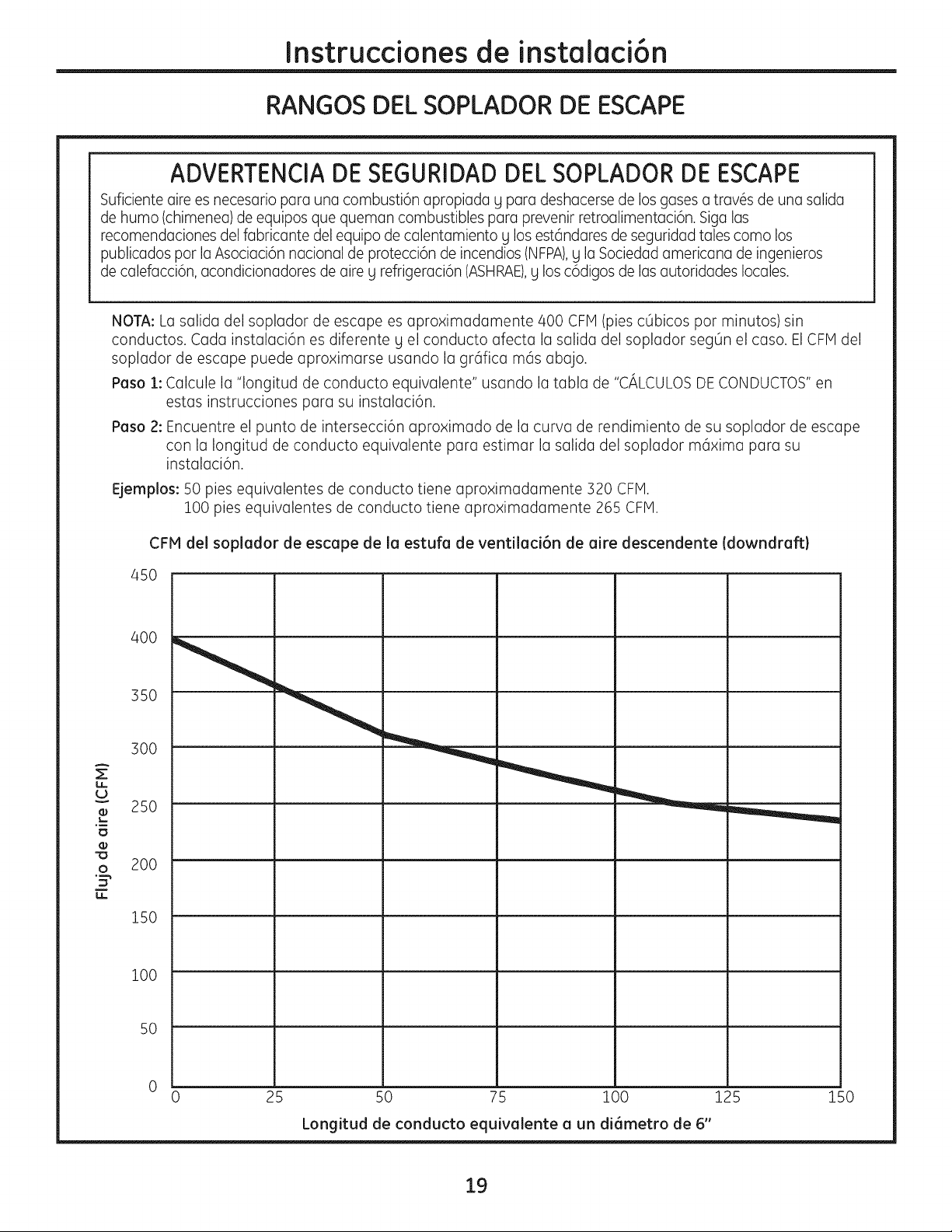
Instruccionesde instalaci6n
RANGOS DEL SOPLADOR DE ESCAPE
ADVERTENCIADESEGURIDADDELSOPLADORDE ESCAPE
Suficienteaire es necesariopara unacombusti6napropiada g para deshacersede losgasesa trav6s de una salida
de humo (chimenea)de equiposque queman combustiblespara prevenirretroalimentaci6n.Sigalas
recomendacionesdel fabricantedel equipo decalentamientog losest6ndaresdeseguridadtalescomo los
publicadospor laAsociaci6nnacionalde protecci6nde incendios(NFPA),g la Sociedadamericanade ingenieros
de calefacci6n,acondicionadoresde aire g reffigeraci6n(ASHRAE),g losc6digosde lasautoridadeslocales.
A
z
U
o_
O
NOTA:La salida del soplador de escape es aproximadamente/400 CFIVl(piesc0bicos pot minutos) sin
conductos. Cada instalaci6n es diferente g el conducto afecta la salida del soplador seg0n el caso. El CFMdel
soplador de escape puede aproximarse usando la grafica mas abajo.
Paso 1: Calcule la "longitud de conducto equivalente" usando la tabla de "CALCULOS DE CONDUCTOS"en
estas instrucciones para su instalaci6n.
Paso 2: Encuentreelpunto de intersecci6naproximado de lacurvade rendimientode su sopladorde escape
con lalongitudde conducto equivalentepara estimarlasalidadelsopladorm6xima para su
instalaci6n.
Ejemplos: 50 pies equivalentes de conducto tiene aproximadamente 320 CFP1.
100 pies equivalentes de conducto tiene aproximadamente 265 CFM.
CFM del soplador de escape de la estufa de ventilaci6n de aire descendente (downdraft)
45O
4OO
35O
300
25O
2OO
150
i00
50
0
0 25 50 75 100 125 150
Longitud de conducto equivalente a un di6metro de 6"
19
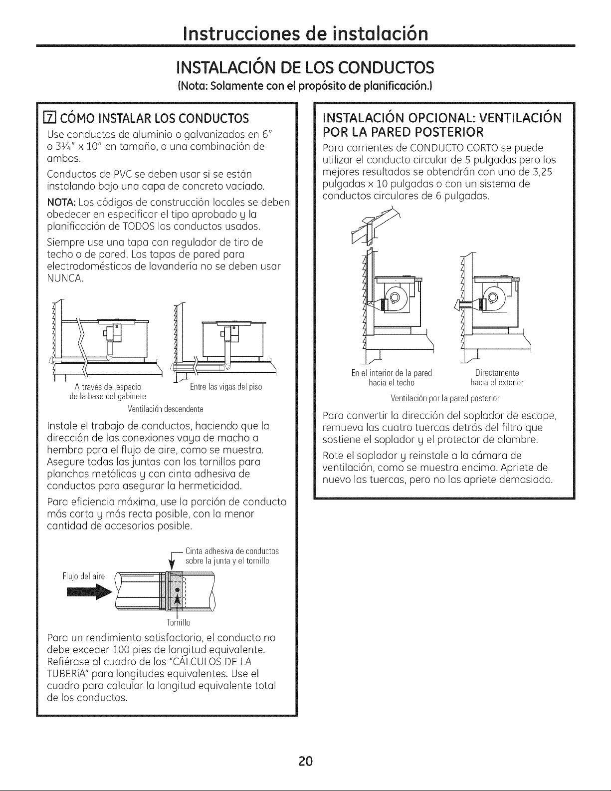
Instruccionesde instalaci6n
INSTALACION DE LOS CONDUCTOS
(Nota: Solamente con el prop6sito de planificaci6n.)
[]COMO INSTALAR LOS CONDUCTOS
Use conductos de aluminio o golvanizados en 6"
o 31/4" x :].0" en tamaho, o una combinaci6n de
ambos.
Conductos de PVC se deben user si se est6n
instalondo bajo una copa de concrete vociado.
NOTA: Los c6digos de construcci6n locales se deben
obedecer en especificor el ripe oprobado g Io
plonificoci6n de TODOS los conductos usodos.
Siempre use una tapa con regulador de tire de
techo o de pared. Las tapas de pared para
electrodom6sticos de lavanderia no se deben usar
NUNCA.
A trav6sdel espacio Entrelasvigasdelpis0
de la basedel gabinete
Ventilaci6ndescendente
Instmle el trmbmjo de conductos, hacienda que la
direcci6n de Iresconexiones vmgu de macho m
hembro pore el flujo de oire, coma se muestra.
Asegure todos los juntos con los tornillos pore
planchms met61icas g con cintra mdhesivm de
conductos parm msegurmr Imhermeticidmd.
Pora eficiencio m6ximo, use Io porci6n de conducto
m6s carte g m6s recta posible, con la menor
cantidad de accesorios posible.
Flujedel aire
Cintaadhesivade conductos
--- sabrela eltornillo
junta
Y
Torlille
Para un rendimiento satisfactorio, el conducto no
debe exceder 100 pies de Ion gitud equivalente.
Refi6rase al cuadro de los "CALCULOS DE LA
TUBERiA" para longitudes equivalentes. Use el
cuadro para calcular la Iongitud equivalente total
de los conductos.
INSTALACION OPCIONAL: VENTILACION
POR LA PARED POSTERIOR
Para corrientes de CONDUCTO CaRTe se puede
utilizar el conducto circular de 5 pulgadas pero los
mejores resultados se obtendr6n con uno de 3,25
pulgadas x 10 pulgadas o con un sistema de
conductos circulares de 6 pulgadas.
i
Enel interior de la pared Directamente
haciael techo hacia el exterior
Ventilaci6nper laparedposterior
Para convertir la direcci6n del soplador de escape,
remueva las cuatro tuercas detr6s del filtro que
sostiene el soplador g el protector de alambre.
Rote el soplador g reinstale a la c6mara de
ventilaci6n, coma se muestra encima. Apriete de
nuevo las tuercas, pete no las apriete demasiado.
2O
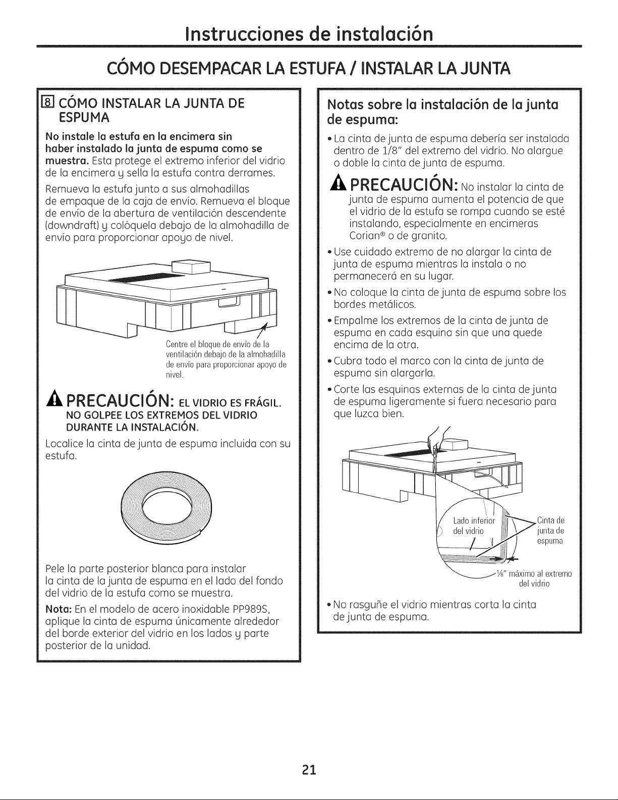
Instruccionesde instalaci6n
C6MO DESEMPACARLA ESTUFA/INSTALAR LA JUNTA
[_] C6MO INSTALAR LA JUNTA DE
ESPUMA
No instale la estufa en la endmera sin
haber instalado la junta de espuma como se
muestra. Esto protege el extremo inferior del vidrio
de la encimera g sella la estufa contra derrames.
Remueva la estufa junto a sus almohadillas
de empaque de la caja de env[o. Remueva el bloque
de envio de la abertura de ventilaci6n descendente
(downdraft) g col6quela debajo de la almohadilla de
env[o pare proporcionar apogo de nivel.
Centreel bloquede envb de la
ventilaci6ndebajode la almohadilla
de envb para proporcionar@eye de
nivel.
PRECAUCI6N: EL VIDRIO ES FR#,GIL.
NO GOLPEE LOS E×TREMOS DEL VIDRIO
DURANTE LA INSTALACION.
Locolice la cinta de junto de espuma incluida con su
estufa.
Pele Io porte posterior blonca poro instalar
la cinta de lajunta de espuma en el lado del fondo
del vidrio de la estufa como se muestra.
Note: En el modelo de acero inoxidable PP989S,
aplique la cinta de espuma 0nicamente alrededor
del borde exterior del vidrio en los lados g porte
posterior de la unidad.
Notas sobre la instalaci6n de la junta
de espuma:
• La cinta de junta de espuma deberia set instalada
dentro de 1/8" del extremo del vidrio. No alargue
o doble la cinta de junta de espuma.
PRECAUCION: No instolor ,acinto de
junto de espumo oumento el potencio de que
el vidrio de Iu estufo se rompo cuondo se est6
instolondo, especiolmente en encimerus
Corion ® o de gronito.
• Use cuidado extremo de no alargar la cinta de
junta de espuma mientras la instala o no
permanecer6 en su lugar.
• No coloque la cinta de junta de espuma sobre los
bordes met61icos.
• Empalme los extremos de la cinta de junta de
espuma en cada esquina sin que una quede
encima de la otra.
Cubra todo el marco con la cinta de junta de
espuma sin alargarla.
Corte las esquinas externas de la cinta de junta
de espuma ligeramente si fuera necesario pare
que luzca bien.
/
\ Cintade
\ _Usnpluardae
" m_ximoal extreme
del vidrio
• No rasgufle el vidrio mientras corta la cinta
de junta de espuma.
21
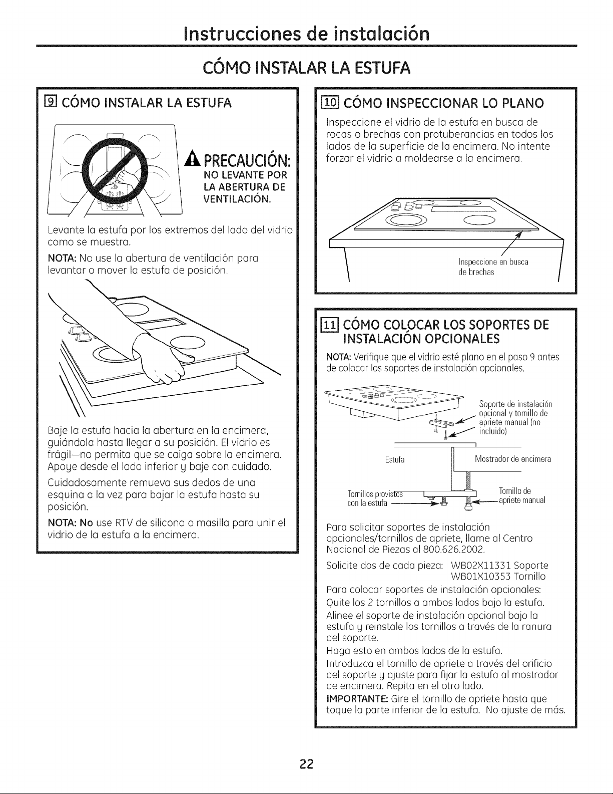
Instruccionesde instalaci6n
C6MO INSTALAR LA ESTUFA
r91 C6MO INSTALAR LA ESTUFA
PRECAUCI6N:
NO LEVANTE POR
LA ABERTURA DE
VENTILACI6N.
Levante la estufa por los extremos del lado del vidrio
como se muestra.
NOTA: No use la abertura de ventilaci6n para
levantar o mover la estufa de posici6n.
Baje la estufa hacia la abertura en la encimera,
gui6ndola hasta Ilegar a su posici6n. El vidrio es
fr6gil-no permita que se caiga sobre la encimera.
Apoge desde el lado inferior g baje con cuidado.
Cuidadosamente remueva sus dedos de una
esquina a la vez para bajar la estufa hasta su
posici6n.
NOTA: No use RTV de silicona o masilla para unir el
vidrio de la estufa a la encimera.
IT0-1C6MO INSPECCIONAR LO PLANO
Inspeccione el vidrio de la estufa en busca de
rocas o brechas con protuberancias en todos los
lados de la superficie de la encimera. No intente
forzar el vidrio a moldearse a la encimera.
Inspeccioneen busca I
de brechas
C6MO COLOCAR LOSSOPORTESDE
INSTALACIONOPCIONALES
NOTA:Verifique que el vidrio est6 piano en el paso 9 antes
de colocar los soportes de instalaci6n opcionales,
Estufa
Tornillosprovistos
conlaestufa
Soportede instalaci6n
opcionaly tornillo de
apriete manual(no
incluido)
1
J Mostradorde encimera
Tornillode
_l_r_.,_____ aprietemanual
Para solicitar soportes de instalaci6n
opcionales/tornillos de apriete, Ilame al Centro
Nacional de Piezas al 800.626.2002.
Solicite dos de cada pieza: WB02X11131 Soporte
WB01X10353 Tornillo
Para colocar soportes de instalaci6n opcionales:
Quite los 2 tornillos a ambos lados bajo la estufa.
Alinee el soporte de instalaci6n opcional bajo la
estufa g reinstale los tornillos a trav6s de la ranura
del soporte.
Haga esto en ambos lados de la estufa.
Introduzca el tornillo de apriete a trav6s del orificio
del soporte g ajuste para fijar la estufa al mostrador
de encimera. Repita en el otro lado.
IMPORTANTE: Gire el tornillo de apriete hasta que
toque la parte inferior de la estufa. No ajuste de m6s.
22
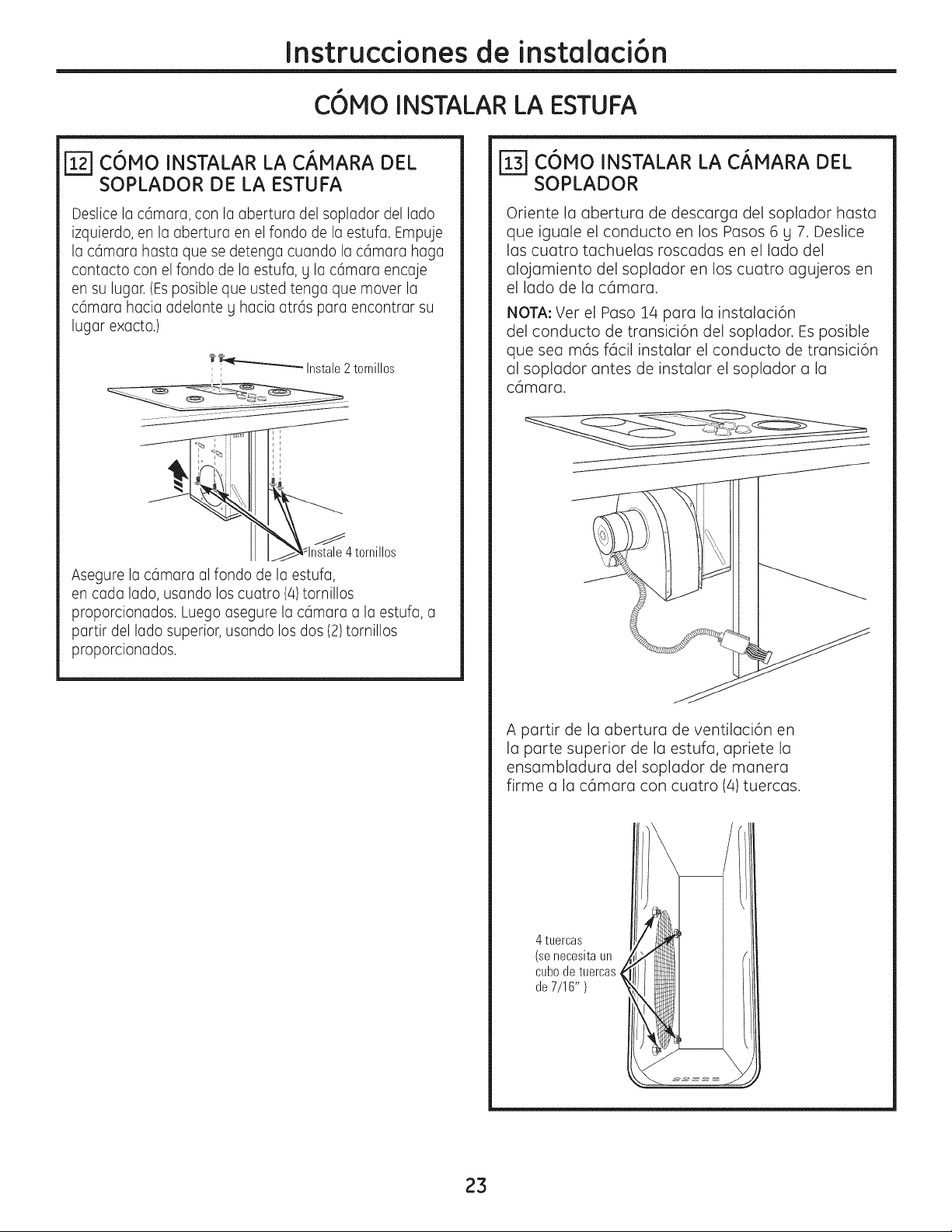
Instruccionesde instalaci6n
C6MO INSTALAR LA ESTUFA
C6MO INSTALAR LA C#,MARA DEL
SOPLADOR DE LA ESTUFA
Deslicela c6mara,con la abertura del sopladordel lado
izquierdo,en la abertura en el rondo de la estufa. Empuje
la c6mara hasta que sedetenga cuandola c6mara haga
contacto con el rondo de la estufa,y la c6mara encaje
en su lugar.(Esposibleque ustedtenga que mover la
c6mara hacia adelantey hacia atr6s para encontrarsu
lugar exacto.)
1_ Instale 2 tornillos
Asegurelac6mara alfondo de la estufa,
en cada lado,usando loscuatro (4)tornillos
proporcionados.Luegoasegurela c6mara a la estufa,a
partir del lado superior,usando los dos(2)tornillos
proporcionados.
C6MO INSTALAR LA C#,MARA DEL
SOPLADOR
Oriente la abertura de descarga del soplador hasta
que iguale el conducto en los Pasos 6 g 7. Deslice
las cuatro tachuelas roscadas en el lado del
alojamiento del soplador en los cuatro agujeros en
el lado de la c6mara.
NOTA: Ver el Paso 14 para la instalaci6n
del conducto de transici6n del soplador. Es posible
que sea m6s f6cil instalar el conducto de transici6n
al soplador antes de instalar el soplador a la
c6mara.
A partir de la abertura de ventilaci6n en
la parte superior de la estufa, apriete la
ensambladura del soplador de manera
firme a la c6mara con cuatro (4)tuercas.
4 tuercas
(senecesitaun
cubode tuercas
de 7/16" )
23
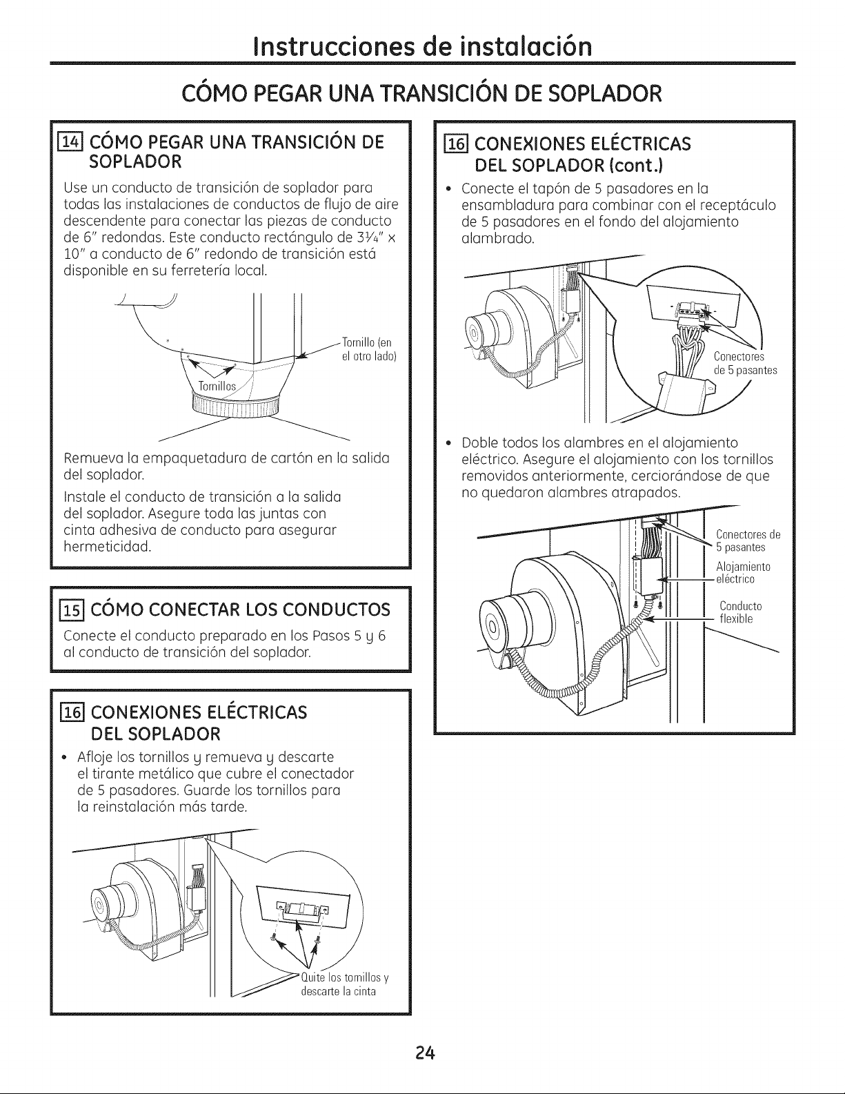
Instruccionesde instalaci6n
C6MO PEGAR UNA TRANSICI6N DE SOPLADOR
C6MO PEGAR UNA TRANSlCI6N DE
SOPLADOR
Use un conducto de transici6n de soplador para
todas las instalaciones de conductos de flujo de aire
descendente para conectar las piezas de conducto
de 6" redondas. Este conducto rect6ngulo de 31/4" x
10" a conducto de 6" redondo de transici6n est6
disponible en su ferreteria local.
Tornillo (en
el etre lade)
Remueva la empaquetadura de cart6n en la salida
del soplador.
Instale el conducto de transici6n a la salida
del soplador. Asegure toda las juntas con
cinta adhesiva de conducto para asegurar
hermeticidad.
C6MO CONECTAR LOS CONDUCTOS
Conecte el conducto preparado en los Pasos 5 g ro
al conducto de transici6n del soplador.
r_ CONE×IONES ELI_CTRICAS
DEL SOPLADOR
Afloje los tornillos g remueva g descarte
el tirante met61ico que cubre el conectador
de 5 pasadores. Guarde los tornillos para
la reinstalaci6n m6s tarde.
lies y
II l_/ descartela cinta
[] CONE×IONES EL#CTRICAS
DEL SOPLADOR (cont.)
Conecte el tap6n de 5 pasadores en la
ensambladura para combinar con el recept6culo
de 5 pasadores en el fondo del alojamiento
alambrado.
Conecteres
de 5 pasantes
Doble todos los alambres en el alojamiento
el6ctrico. Asegure el alojamiento con los tornillos
removidos anteriormente, cercior6ndose de que
no quedaron alambres atrapados.
Cenecteresde
_" Bpasantes
Alejamiente
--el6ctrice
Cenducte
flexible
24
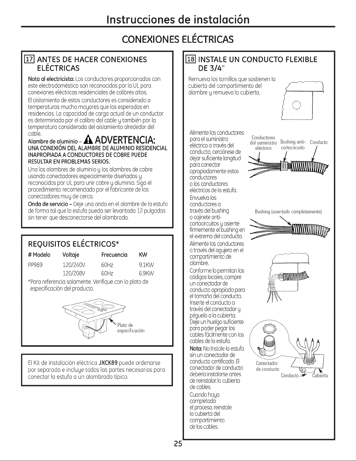
Instruccionesde instalaci6n
CONE×laNES ELI CTRICAS
ANTES DE HACER CONEXIONES
ELI_CTRICAS
Nota al electricista: Losconductores proporcionados con
este electrodom6stico son reconocidos par la ULpara
conexiones el6ctricas residencialesde calibresaltos.
Elaislamiento de estos conductores es considerado a
temperaturas mucho magores que las esperadas en
residencias.La capacidad de cargo actual de un conductor
es determinado par el calibre del cable g tambi6n par la
temperatura considerada del aislamiento alrededor del
cable.
Aiambre de alumJnio - _ ADVERTENCIA:
UNA CONE×I6N DELALAMBREDEALUMINIO RESlDENCIAL
INAPROPIADAA CONDUCTORESDE COBREPUEDE
RESULTAREN PROBLEMASSERIOS.
Una los alambres de aluminio g los alambres de cobre
usando conectadores especialmente disenados g
reconocidos por UL para unir cobre y aluminio.Siga el
procedimiento recomendado por el fabricante de los
conectadores muy de cerca.
Onda de servicio - Deje una onda en el alambre de la estufa
de forma tal que la estufa pueda ser levantada 12 pulgadas
sin tener que desconectarse delalambrado.
REOUISITOS ELI_CTRICOS*
# Modelo Voltaje Frecuencia KW
PP989 120/240V 60Hz 9.1KW
120/208V 60Hz 6.9KW
*Para referenciasolamente. Verifique con la plato de
especificaci6n del producto.
de
cificaci6n
El Kit de instalaci6n el6ctrica J×CK89 puede ordenarse
par separado e incluge todas las partes necesarias para
conectar la estufa a un alambrado @ico.
25
r_1 INSTALE UN CONDUCTO FLEXIBLE
DE 314"
Remuevalos tornillos que sostienen la
cubierta del compartimiento del
alambre g remueva la cubierta.
Alimentelosconductores
parael suministro
el6ctricoa trav6sdel
conducto;cerci6resede
@jar suficienteIongitud
paraconectar
apropiadamenteestos
conductores
a losconductores
el6ctricosdela estufa.
Envuelvalos
conductoresa
trav6sdel bushing
o cojineteanti-
cortocircuitosg asiente
firmementeel bushingen
elextremodelconducto.
Alimentelosconductores
a trav6sdel agujeroenel
compartimientode
alambre.
ConformeIopermitan los
c6digoslocales,compre
un conectadorde
conductoapropiado para
eltamano del conducto.
Inserteelconductoa
trav6sdel conectadorg
p6gueloa lacubierta.
Dejeun huelgosuficiente
para poderpegarlos
cablesf6cilmentecon los
cablesdela estufa.
Nota: No Instalelaestufa
sinun conectadorde
conductocertificado.El
conectadorde conducto
deberfainstalarseantes
de reinstalarlacubierta
decables.
Cuandohaga
completado
elproceso,reins'tale
lacubierta del
compartimiento
de loscables.
Conductores
del suministro Bushinganti- Conducto
el6ctrico cortocircuito
Bushing(asentadocompletamente)
Conectador
de conducto
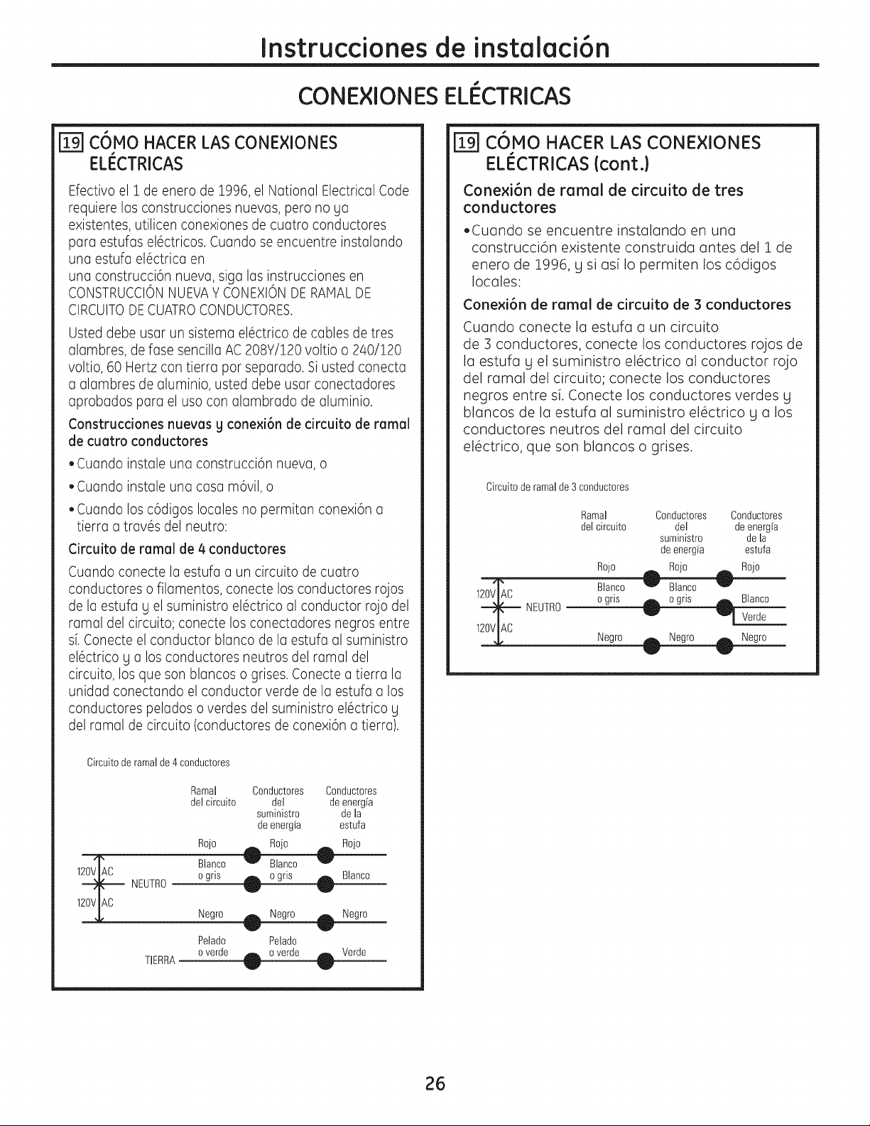
Instruccionesde instalaci6n
CONE×IONES ELI CTRICAS
r_ c6Mo HACER LAS CONE×IONES
ELI_CTRICAS
Efectivo el i de enero de 1996,el National Electrical Code
requiere las construcciones nuevas, pero no ga
existentes, utilicen conexiones de cuatro conductores
para estufas el6ctricos. Cuando se encuentre instalando
una estufa el6ctrica en
una construcci6n nueva, siga las instrucciones en
CONSTRUCCIONNUEVAY CONEXIONDE RAMAL DE
CIRCUITODE CUATROCONDUCTORES.
Usted debe usar un sistema el6ctrico de cables de tres
alambres, de fase sencilla AC 208Y/120 voltio o 240/120
voltio, 60 Hertz con tierra por separado. Si usted conecta
a alambres de aluminio, usted debe usar conectadores
aprobados para el uso con alambrado de aluminio.
Construcciones nuevas y cone×i6n de circuito de ramal
de cuatro conductores
• Cuando instale una construcci6n nueva, o
• Cuando instale una casa m6vil, o
• Cuando los c6digos locales no permitan conexi6n a
tierra a trav6s del neutro:
Circuito de ramal de 4 conductores
Cuando conecte la estufa a un circuito de cuatro
conductores o filamentos, conecte los conductores rojos
de la estufa y el suministro el6ctrico al conductor rojo del
ramal del circuito; conecte los conectadores negros entre
sf. Conecte el conductor blanco de la estufa al suministro
el6ctrico g a los conductores neutros del ramal del
circuito, los que son blancos o grises. Conecte a tierra la
unidad conectando el conductor verde de la estufa a los
conductores pelados o verdes del suministro el6ctrico g
del ramal de circuito (conductores de conexi6n a tierra).
Circuitode ramalde 4 conductores
Ramal Conductores Conductores
delcircuito del deenergfa
suministre de la
de energia estufa
Rojo t mojo __ Rojo
B_anco w Blanco
1 NEUTRO o gns _ Blanco
120VIAC
Negro Negro Negro
Pelado Pelado
o verde Verde
TIERRA
jTgJC6MO HACER LAS CONE×IONES
ELI_CTRICAS (cont.)
ConexJ6n de ramal de circuito de tres
conductores
• Cuando se encuentre instalando en una
construcci6n existente construida antes del 1 de
enero de 1996, g si asi Io permiten los c6digos
locales:
Conexi6n de ramal de circuito de 3 conductores
Cuando conecte la estufa a un circuito
de :3 conductores, conecte los conductores rojos de
la estufa g el suministro el6ctrico al conductor rojo
del ramal del circuito; conecte los conductores
negros entre si. Conecte los conductores verdes g
blancos de la estufa al suministro el6ctrico g a los
conductores neutros del ramal del circuito
el6ctrico, que son blancos o grises.
Circuitede ramalde 3 conductores
Ramal Cenductores Conducteres
del circuite del de energfa
suministre de la
de energfa estufa
mojo ._ Rojo t Rojo
BTnco _ Bianco "_
• " Blanco
1 NEUTRO o gns _ o grls _£
v I
Verde
120VlAC
Negro _ Negro
26
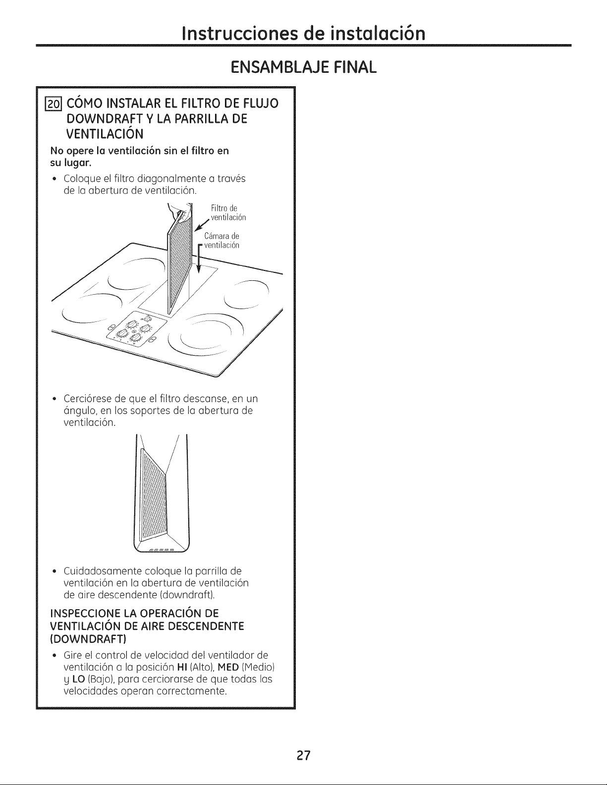
Instruccionesde instalaci6n
ENSAMBLAJE FINAL
r_ C6MO INSTALAR EL FILTRO DE FLUJO
DOWNDRAFT Y LA PARRILLA DE
VENTILACI6N
No opere Io ventiloci6n sin el filtro en
su lugor.
• Coloque el filtro diagonalmente a trav6s
de la abertura de ventilaci6n.
Filtrode
jventilaci6n
CSmarade
- ventilaci6n
• Cerci6rese de que el filtro descanse, en un
6ngulo, en los soportes de la abertura de
ventilaci6n.
• Cuidadosamente coloque la parrilla de
ventilaci6n en la abertura de ventilaci6n
de aire descendente (downdraft).
INSPECCIONE LA OPERACI6N DE
VENTILACI6N DE AIRE DESCENDENTE
(DOWNDRAFT)
• Gire el control de velocidad del ventilador de
ventilaci6n a la posici6n HI (Alto), MED (IVledio)
g LO (Bajo), para cerciorarse de que todas las
velocidades operan correctamente.
27
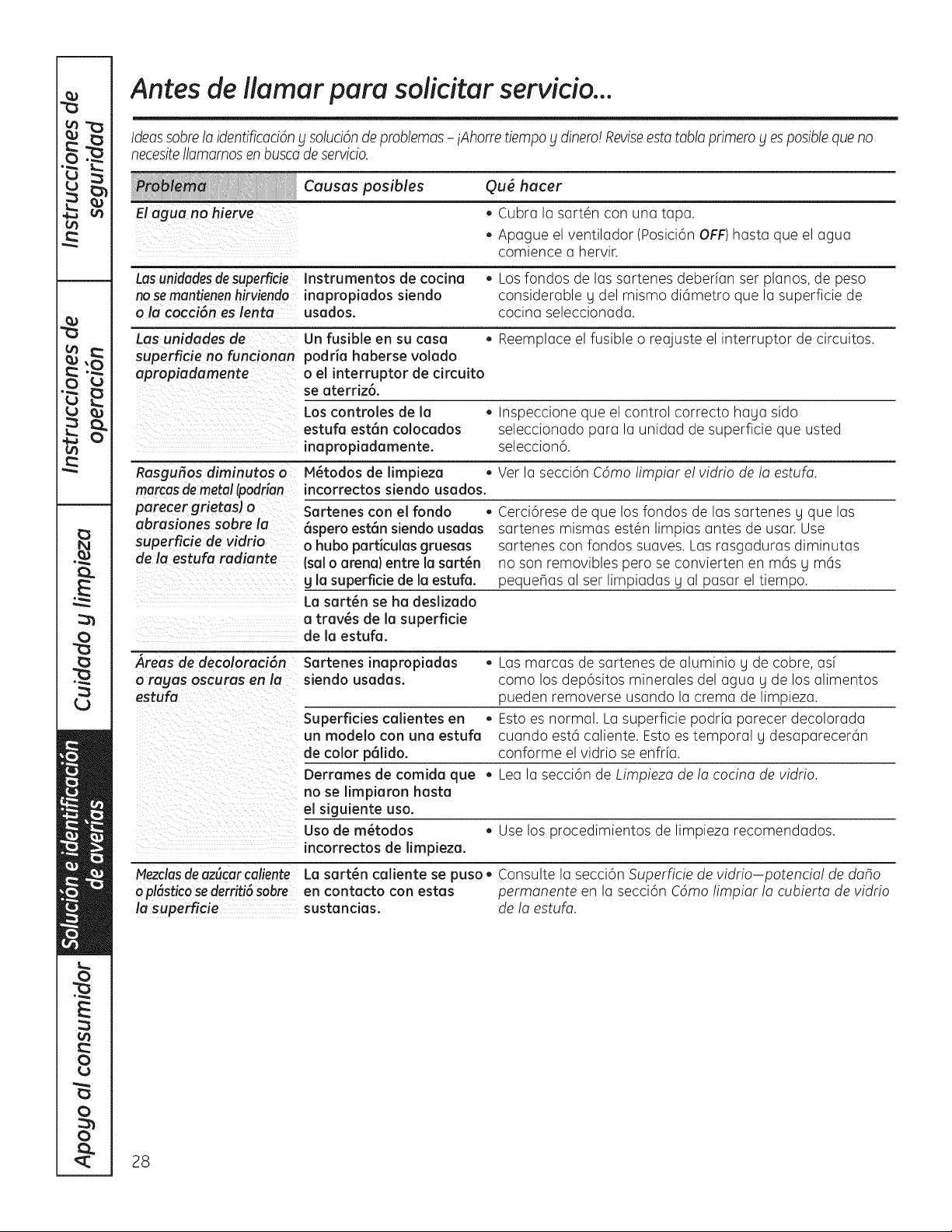
Antes de ilamar pare solicitar servicio...
Ideassabra la identificaci6ny soluci6nde problemas- iAhorm tiempo y dinero! Reviseesta table primate yes posiblequa no
necesiteIlamamos enbusca deservicio.
Causes posibles Qu_ hacer
El agua no hierve • Cubra la soften con una tape.
• Apague el ventilador (Posici6n OFF) hasta que el agua
comience a hervir.
Lasunidadesdesuperficie Instrumentos de codna • Los fondos de las sartenes deberfan ser pianos, de peso
nosemantienenhirviendo inapropiados siendo considerable y del mismo di6metro que la superficie de
o la cocci6n es lenta usados, cocina seleccionada.
Las unidades de Un fusible en su case • Reemplace el fusible o reajuste el interrupter de circuitos.
superficie no funcionan podria haberse volado
apropiadamente o el interrupter de drcuito
se aterriz6.
Los controles de la • Inspeccione que el control correcto haya side
estufa est6n colocados seleccionado para la unidad de superficie que usted
inapropiadamente, seleccion6.
Rasgufios diminutos o N_todos de limpieza • Vet la secci6n Cdmo !impiar e! vidrio de !a estufo.
marcasde metal(podrian incorrectos siendo usados.
parecergrietas) o Sartenes con el rondo •
abrasiones sabre la 6spero est6n siendo usadas
superficie de vidrio o hubo particulas gruesas
de la estufa radiante (sal o arena) entre la sart_n
g la superfide de la estufa.
La sart_n se ha deslizado
a troves de la superficie
de la estufa.
Cerci6rese de que los fondos de los sartenes y que las
sartenes mismas estOn limpias antes de usar. Use
sartenes con fondos suaves. Las rasgaduras diminutas
no son removibles pero se convierten en m6s y m6s
pequeflas al ser limpiadas g al pasar el tiempo.
,_reas de decoloraci6n Sartenes inapropiadas • Las marcas de sartenes de aluminio U de cobre, asf
o rayas oscuras en la siendo usadas, coma los dep6sitos minerales del agua U de los alimentos
estufa pueden removerse usando la creme de limpieza.
Superficies calientes en • Esto es normal. La superficie podrfa parecer decolorada
un modelo con una estufa cuando est6 caliente. Esto es temporal y desaparecer6n
de color p61ido, conforme el vidrio se enfrfa.
Derrames de comida que • Lea la secci6n de Limpieza de !a cocina de vidrio.
no se limpiaron haste
el sJguiente usa.
Usa de m_todos • Use los procedimientos de limpieza recomendados.
incorrectos de limpieza.
MezclasdeazScarcaliente
oplSsticosederriti6 sabre
,fasuperficie sustandas.
La sart_n caliente se puso • Consulte la secci6n Superficie de vidrio-potencia! de daho
en contacto con estas permanente en la secci6n Cdmo limpiar la cubierta de vidrio
de la estufa.
28
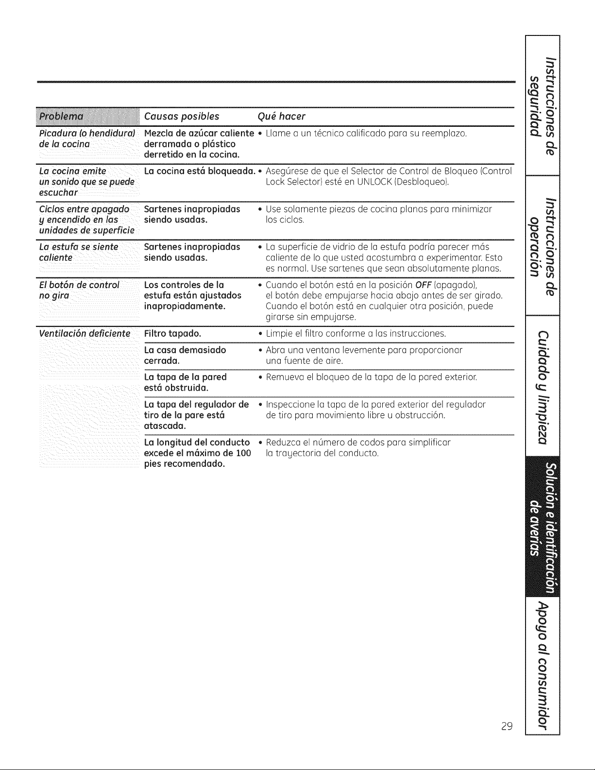
Causas posibles Qu6 hacer
Picadura (a hendidura) Mezda de az6car caliente • Llame a un t6cnico calificado para su reemplazo.
de la cacina derramada o plOstico
derretido en la cocina.
La cocina emite La cocina est6 bloqueada. • Aseg0rese de que el Selector de Control de Bloqueo (Control
un sonido que se puede Lock Selector) est6 en UNLOCK(Desbloqueo).
escuchar
Ciclos entre apagada Sartenes inapropiadas • Use solamente piezas de cocina planas para minimizar
g encendida en las siendo usadas, los cicIos.
unidades de superficie
La estufa se siente Sartenes inapropiadas • La superficie de vidrio de la estufa podrfa parecer m6s
caliente siendo usadas, caliente de Io que usted acostumbra a experimentar. Esto
es normal. Use sartenes que sean absolutamente planas.
El Oo-t6nde contr_ Los controles de la • Cuando el bot6n est6 en la posici6n OFF (apagado),
no gira estufa estOn ajustados el bot6n debe empujarse hacia abajo antes de set girado.
inapropiadamente. Cuando el bot6n est6 en cualquier otra posici6n, puede
girarse sin empujarse.
Ventilaci6n deficiente Filtro tapado. • Limpie el filtro conforme a los instrucciones.
La casa demasiado • Abra una ventana levemente para proporcionar
cerrada, una fuente de aire.
La tapa de la pared • Remueva el bloqueo de la tapa de la pared exterior.
est6obstruida.
La tapa del regulador de • Inspeccione la tapa de la pared exterior del regulador
tiro de la pare est6 de tiro para movimiento libre u obstrucci6n.
atascada.
La Iongitud del conducto • Reduzca el nOmero de codos para simplificar
e×cede el m6×imo de 100 la tragectoria del conducto.
pies recomendado.
29
va
V
::m
"0
v
o
E
0
0
0
C3.
Notas.
3O
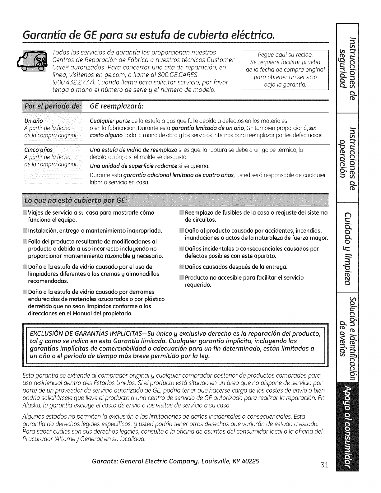
Garantia de GEpara su estufa de cubierta d ctfico.
Todos los servicios de garantia los proporcionan nuestros
Centros de ReparaciOn de Fdbrica o nuestros t4cnicos Customer
Care ® autorizados. Para concertar una cita de reparaciOn, en
finea, visftenos en ge.com, o Ilame a1800.GE.CARES
(800.432.2737). Cuando Ilame para solicitar servicio, par favor
tenga a maria el nOmero de serie g el nOmero de modelo.
Pegue aquf su recibo.
Se requiem facilitar prueba
de la fecha de compra origina!
para obtener un servicio
ba]o la garantfa.
GE reemplazar(7:
Un afro
A partir de Io fecho
de Io compm original
Cualquierparte de la estufa a gas que falle debido a defectos en los materiales
o en la fabricaci6n. Durante esta garani;fa limitada de un a_o, GEtambi_n proporcion6, sin
costa alguno, toda la mona de obra g los servicios internos para reemplazar partes defectuosas.
Cinco a_os
A partir de Io fecha
de la compm origina!
Una estufa de vidrio de reemplazo si es que: la ruptura se debe a un golpe t@rmico;la
decoloraci6n; o si el molde se desgasta.
Una unidad de superficie radiante si se quema.
Durante esta garantia adicional limitada de cuatro arias, usted ser6 responsablede cualquier
labor o servicio en casa.
Viajes de servido a su casa pare mostmrle c6mo
fundona el equ0o.
Instalaci6n, entrega o mantenimiento inapropdada.
Fallo del producto resultante de modificadones al
producto o debido a usa incorrecto inclugendo no
propordonar mantenimiento razonable g necesano.
Daffo a la estufa de viddo causado par el usa de
limpiadores diferentes a las cremas g almohadillas
recomendadas.
Daffo a la estufa de viddo causado par dermmes
endurecidos de matedales azucamdos o par pl6stico
derretido que no sean limpiados conforme alas
direcciones en el Manual del pmpietario.
Reemplazo de fusibles de la casa o reajuste del sistema
de drcuitos.
Da5o al producto causado por accidentes, incendios,
inundaciones o actos de la naturaleza de fuerza magor.
Dafos incidentales o consecuenciales causados por
defectos posibles con este aparato.
Dafos causados despu_s de la entrega.
Producto no accesible para facilitar el servicio
requerido.
EXCLUSI6N DE GARANT[AS IMPL[CITAS--Su (mica g exclusivo derecho es la reparaci6n del producto,
tal g come se indica en esta Garantia limitada. Cualquier garantia implicita, inclugendo las
garantias implicitas de comerciabilidad o adecuaci6n para un fin determinado, estSn limitadas a
un aho o el periodo de tiempo ross breve permitido par la leg.
Esta garantia se extiende al compmdor original g cualquier compmdor posterior de pmductos comprados pare
usa residencial dentin des Estados Unidos. Si el producto estd situado en un drea que no dispone de servicio par
porte de un pmveedor de servicio autofizado de GE, podria tener que hacerse cargo de los castes de envio o bien
podria solicitdrsele que Ileve el pmducto a una centro de servicio de GE autorizado para realizar la reparaci6n. En
Alaska, la garantia excluge el costa de envio o los visitas de servicio a su casa.
Algunos estados no permiten la exclusi6n olas limitaciones de dahos incidentales o consecuenciales. Esta
garantia da derechos legales especificos, bl usted podria tener arms derechos que variardn de estado a estado.
Para saber cudles son sus derechos legales, consulte a la oficina de asuntos del consumidor local o la oficina del
Prucumdor (Attomeg General) en su Iocalidad.
Garante: General Electric Compang. Louisville, KY 40225
51
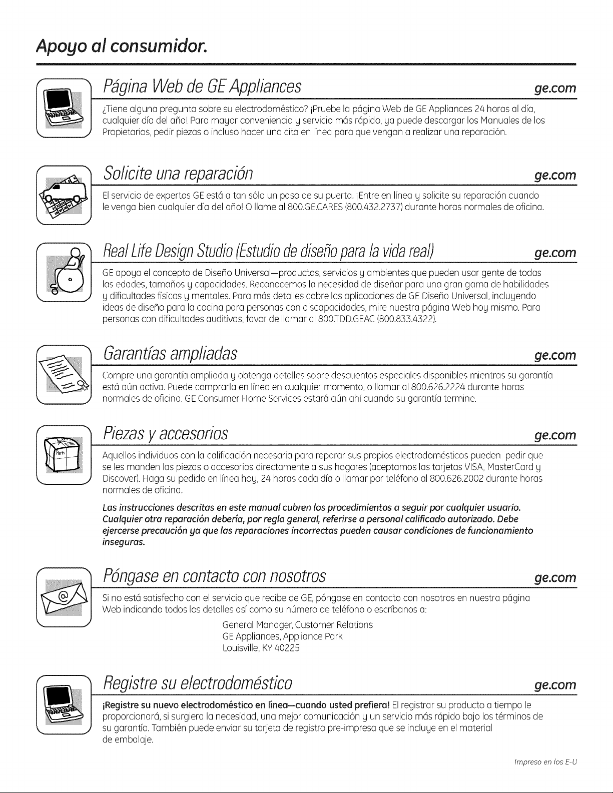
Apogo a! consumidor.
P_ginaWebde GEAppliances
ge.com
¢Tienealguna pregunta sabre su electrodom@stico?iPruebela p6gina Web de GEAppliances 24 horas al dfa,
cualquier dfa del aho! Para mayor conveniencia y servicio m6s r6pido, ya puede descargar los Hanuales de los
Propietarios, pedir piezaso incluso hacer una cita en Ifneapara que vengan a realizar una reparaci6n.
SoliciteunareparaciDn ge.com
Elservicio de expertos GE est6 a tan s61oun paso de su puerta, iEntre en Ifneag solicite su reparaciSn cuando
le venga bien cualquier dfa del aho! O Ilame al 800.GE.CARES(800.432.2737)durante horas normales de oficina.
RealLifeDesignStudio(Estudiodedisefioparalavidareal)
ge.com
GEapoyu el concepto de DisehoUniversal-productos, servicios y ambientes que pueden usar gente de todas
las edades,tamahos y capacidades. Reconocemos la necesidadde disehar para una gran gama de habilidades
g dificultades fisicas y mentales. Para m6s detalles cobre las aplicaciones de GEDiseho Universal,incluyendo
ideas de diseho para la cocina para personas con discapacidades, mire nuestra pcigina Web hog mismo. Para
personas con dificultades auditivas,favor de Ilamar al 800.TDD.GEAC(800.833.4322).
garantfasamplbdas
ge.com
Compre una garantfa ampliada y obtenga detalles sabre descuentos especialesdisponibles mientras su garantfa
estcia0n activa. Puedecomprarla en Ifneaen cualquier momenta, o Ilamar al 800.626.2224 durante horas
normales de oficina. GEConsumer Home Servicesestarcia0n ahf cuando su garantfa termine.
Piezasy accesorios
ge.com
Aquellos individuos con la calificaciSn necesaria para reparar sus propios electrodom_sticos pueden pedir que
se lesmanden las piezaso accesorios directamente a sus hogares (aceptamos las tarjetas VISA,MasterCard y
Discover).Haga su pedido en Ifnea hog, 2/4horas cada dfa o Ilamar par teldono al 800.626.2002 durante horas
normales de oficina.
Las instrucciones descritas en este manual cubren los procedimientos a seguir por cualquier usuario.
Cualquier otra reparaci6n deberia, par regla general, referirse a personal calificado autorizado. Debe
ejercerse precauci6n ga que las reparaciones incorrectas pueden causar condiciones de funcionamiento
inseguras.
PDngaseen contactoconnosotros
Sino estcisatisfecho con el servicio que recibe de GE,pSngase en contacto con nosotros en nuestra pcigina
Web indicando todos los detalles asf coma su n0mero de teldono o escrfbanos a:
General Manager,Customer Relations
GEAppliances,Appliance Park
Louisville,KY40225
ge.com
Registresu electrodom_stico
ge.com
iRegistre su nuevo electrodom_stico en linea--cuando usted prefiera! Elregistrar su producto a tiempo le
proporcionarci, si surgiera la necesidad, una mejor comunicaciSn y un servicio mcis rcipido bajo los t#rminos de
su garantfa. Tambi#n puede enviar su tarjeta de registro pre-impresa que se incluye en el material
de embalaje.
Impreso en los E-U