
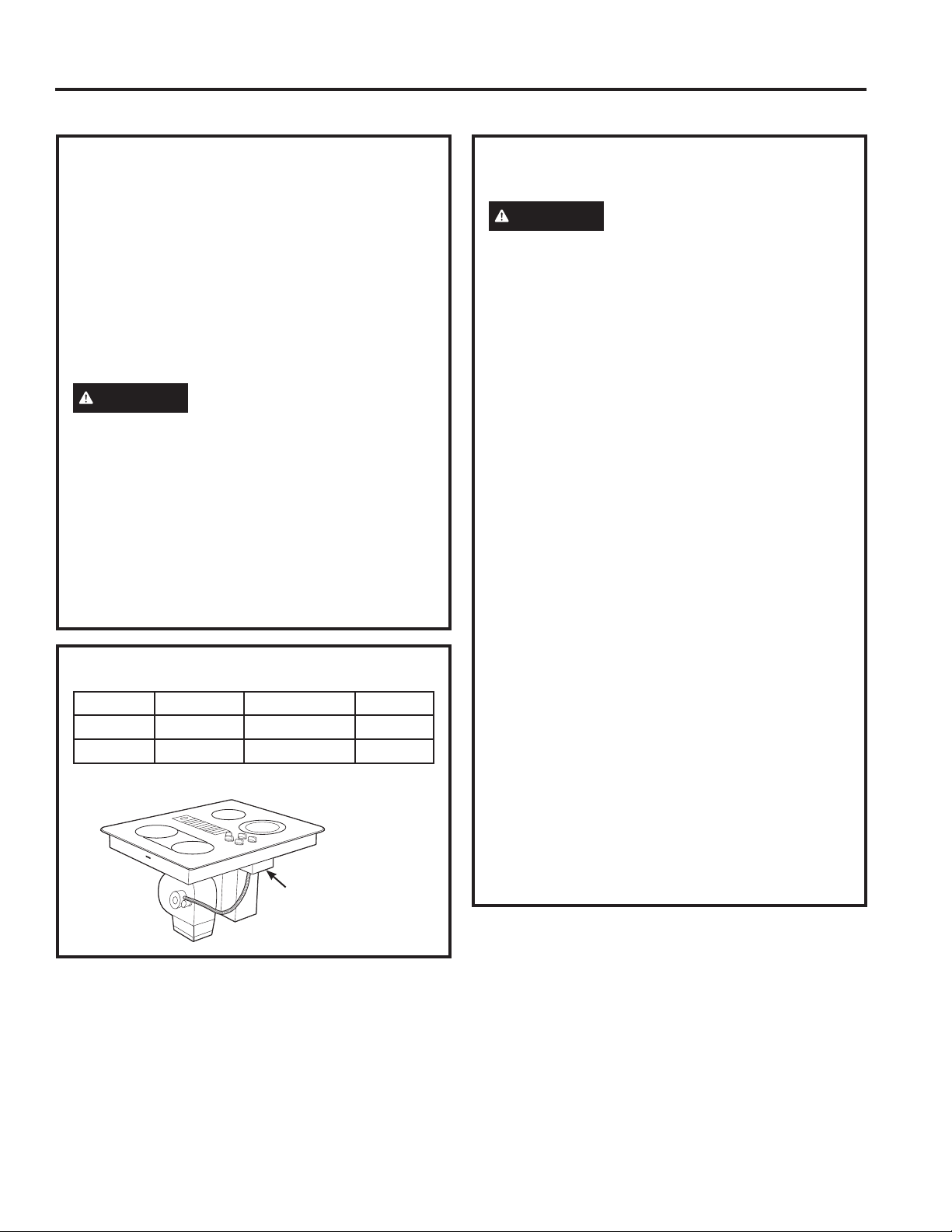
Write the model and serial
numbers here:
Model # _________________
Serial # _________________
Find these numbers on a label
under the cooktop.
ESPAÑOL
Para consultar una version en
español de este manual de
instrucciones, visite nuestro sitio de
internet GEAppliances.com.
OWNER’S MANUAL AND
INSTALLATION INSTRUCTIONS
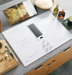
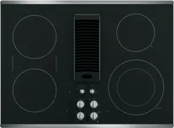
COOKTOP
Radiant Downdraft
49-2001160 Rev. 0 09-22 GEA
PP9830
GE is a trademark of the General Electric Company. Manufactured under trademark license.
ENGLISH
SAFETY INFORMATION ............3
USING THE COOKTOP
Cooktop Features .........................6
Surface Burners ..........................7
Cookware for Radiant
Glass Cooktop .........................10
CARE AND CLEANING
Cleaning the Cooktop .................... 11
Cleaning the Glass Cooktop ...............12
INSTALLATION INSTRUCTIONS ..14
Before You Begin ........................14
Unpacking the Cooktop ..................16
Installation Preparation ...................17
Cooktop Installation .................... 20
TROUBLESHOOTING TIPS .........25
LIMITED WARRANTY ..............26
ACCESSORIES ......................27
CONSUMER SUPPORT .............28

2 49-2001160 Rev. 0
THANK YOU FOR MAKING GE APPLIANCES A PART OF YOUR HOME.
Whether you grew up with GE Appliances, or this is your first, we’re happy to have you in the family.
We take pride in the craftsmanship, innovation and design that goes into every GE Appliances
product, and we think you will too. Among other things, registration of your appliance ensures that we
can deliver important product information and warranty details when you need them.
Register your GE appliance now online. Helpful websites and phone numbers are available in the
Consumer Support section of this Owner’s Manual. You may also mail in the pre-printed registration
card included in the packing material.
49-2001160 Rev. 0 3
READ AND SAVE THESE INSTRUCTIONS
IMPORTANT SAFETY INFORMATION
READ ALL INSTRUCTIONS BEFORE USING THE APPLIANCE
SAFETY INFORMATION
WARNING
Read all safety instructions before using the product. Failure to follow these instructions may result
in fire, electrical shock, serious injury or death.
WARNING
GENERAL SAFETY INSTRUCTIONS
Ŷ 8VHWKLVDSSOLDQFHRQO\IRULWVLQWHQGHGSXUSRVHDV
described in this Owner’s Manual.
Ŷ +DYH\RXUFRRNWRSLQVWDOOHGDQGSURSHUO\JURXQGHG
by a qualified installer, in accordance with the
Installation Instructions.
Ŷ $Q\DGMXVWPHQWUHSDLURUVHUYLFHQRWVSHFLILFDOO\
recommended in this manual should be performed
ONLY by a qualified cooktop installer or service
technician.
Ŷ %HIRUHSHUIRUPLQJDQ\VHUYLFHXQSOXJWKHFRRNWRS
or disconnect the power supply at the household
distribution panel by removing the fuse or switching
off the circuit breaker.
Ŷ %HVXUHDOOSDFNLQJPDWHULDOVDUHUHPRYHGIURPWKH
cooktop before operating to prevent ignition of these
materials.
Ŷ 'RQRWOHDYHFKLOGUHQDORQHRUXQDWWHQGHGLQDQ
area where an appliance is in use. They should
never be allowed to climb, sit or stand on any part
of the appliance.
Ŷ
CAUTION
'RQRWVWRUHLWHPVRILQWHUHVWWR
children in cabinets above a range/rangetop —
children climbing on the range to reach items could
be seriously injured.
Ŷ 'RQRWDOORZDQ\RQHWRFOLPEVWDQGRUKDQJRQWKH
rangetop.
Ŷ 8VHRQO\GU\SRWKROGHUV²PRLVWRUGDPSSRW
holders on hot surfaces may result in burns from
VWHDP'RQRWOHWSRWKROGHUVWRXFKKRWVXUIDFH
XQLWVRUKHDWLQJHOHPHQWV'RQRWXVHDWRZHORU
other bulky cloth in place of pot holders.
Ŷ 1HYHUXVH\RXUDSSOLDQFHIRUZDUPLQJRUKHDWLQJ
the room.
Ŷ 'RQRWWRXFKWKHVXUIDFHHOHPHQWV7KHVHVXUIDFHV
may be hot enough to burn even though they are
GDUNLQFRORU'XULQJDQGDIWHUXVHGRQRWWRXFK
or let clothing or other flammable materials contact
the surface units or areas nearby the surface units;
allow sufficient time for cooling first. Other surfaces
of the appliance may become hot enough to cause
burns. Potentially hot surfaces include the cooktop
and areas facing the cooktop.
Ŷ 'RQRWKHDWXQRSHQHGIRRGFRQWDLQHUV3UHVVXUH
could build up and the container could burst,
causing an injury.
WARNING
KEEP FLAMMABLE MATERIALS AWAY FROM THE COOKTOP
Ŷ
WARNING
FIRE HAZARD: Never leave
the range unattended with the cooktop ON. Keep
flammable items away from the cooktop. Turn off all
controls when done cooking. Failure to follow these
instructions can result in fire, serious injury or death.
Ŷ $OZD\VNHHSFRPEXVWLEOHZDOOFRYHULQJVFXUWDLQVRU
drapes a safe distance from your cooktop.
Ŷ 'RQRWSODFHRUVWRUHLWHPVWKDWFDQPHOWRUFDWFK
fire on the glass cooktop, even when it is not
being used. Keep appliance area clear and free
from combustible materials, gasoline, and other
flammable vapors and liquids. If the cooktop is
inadvertently turned on, they may ignite. Heat from
the cooktop or oven vent after it is turned off may
cause them to ignite also.
Ŷ 'RQRWSODFHPHWDOOLFREMHFWVVXFKDVNQLYHVIRUNV
spoons, and lids on the cooktop surface since they
can get hot.
Ŷ 1HYHUZHDUORRVHILWWLQJRUKDQJLQJJDUPHQWVZKLOH
using the appliance. These garments may ignite if
they contact hot surfaces causing severe burns.
Ŷ'RQRWOHWFRRNLQJJUHDVHRURWKHUIODPPDEOH
materials accumulate on or near the cooktop.
Grease on the cooktop may ignite.
Ŷ&OHDQYHQWLODWLQJKRRGVIUHTXHQWO\*UHDVHVKRXOG
not be allowed to accumulate on the hood or filter.
4 49-2001160 Rev. 0
SAFETY INFORMATION
READ AND SAVE THESE INSTRUCTIONS
IMPORTANT SAFETY INFORMATION
READ ALL INSTRUCTIONS BEFORE USING THE APPLIANCE
WARNING
RADIANT COOKTOP SAFETY INSTRUCTIONS
Ŷ
WARNING
NEVER operate the top surface
cooking section of this appliance unattended.
%RLORYHUVFDXVHVPRNLQJDQGJUHDV\VSLOORYHUVWKDW
may catch on fire. Failure to follow this warning
statement could result in fire, explosion, or burn
hazard that could cause property damage, personal
injury, or death.
Ŷ )RRGVHVSHFLDOO\RLO\IRRGVPD\LJQLWHUHVXOWLQJLQ
fire that could spread to surrounding cabinets. If a
fire should occur, keep away from the appliance and
immediately call your fire department.
Ŷ 1HYHUOHDYHRLOXQDWWHQGHGZKLOHIU\LQJ,IDOORZHG
to heat beyond its smoking point, oil may ignite
resulting in fire that may spread to surrounding
FDELQHWV'2127$77(03772(;7,1*8,6+$1
OIL/GREASE FIRE WITH WATER.
Ŷ 'RQRWXVHZDWHURQJUHDVHILUHV1HYHUSLFNXS
a flaming pan. Turn the controls off. Smother a
flaming pan on a surface unit by covering the pan
completely with a well-fitting lid, cookie sheet or flat
tray, or use a multipurpose dry chemical or foam-
type fire extinguisher.
Ŷ 8VHDGHHSIDWWKHUPRPHWHUZKHQHYHUSRVVLEOHWR
monitor oil temperature. To avoid oil spillover and
fire, use the minimum amount of oil when using a
shallow pan-frying and avoid cooking frozen foods
with excessive amounts of ice.
Ŷ 8VHSURSHUSDQVL]H²VHOHFWFRRNZDUHKDYLQJ
flat bottoms large enough to cover the surface
heating element. The use of undersized cookware
will expose a portion of the surface unit to direct
contact and may result in ignition of clothing. Proper
relationship of cookware to surface unit will also
improve efficiency.
Ŷ :KHQXVLQJJODVVFHUDPLFFRRNZDUHPDNHVXUH
it is suitable for cooktop service; others may break
because of sudden change in temperature.
Ŷ 7RPLQLPL]HWKHSRVVLELOLW\RIEXUQVLJQLWLRQRI
flammable materials and spillage, the handle of a
container should be turned toward the center of the
range without extending over nearby surface units.
Ŷ :KHQSUHSDULQJIODPLQJIRRGVXQGHUDKRRGWXUQ
the fan on.
Ŷ 8VHFDUHZKHQWRXFKLQJWKHFRRNWRS7KHJODVV
surface of the cooktop will retain heat after the
controls have been turned off.
Ŷ ,ISRZHULVORVWWRDQHOHFWULFFRRNWRSZKLOHDVXUIDFH
unit is ON, the surface unit will turn back on as
soon as power is restored. In the event of power
loss, failure to turn all surface unit knobs to the OFF
position may result in ignition of items on or near the
cooktop, leading to serious injury or death.
Ŷ $YRLGVFUDWFKLQJRULPSDFWLQJWKHJODVVFRRNWRS
'RLQJVRPD\OHDGWREURNHQJODVV7KHFRRNWRS
can be scratched with items such as knives, sharp
instruments, rings or other jewelry, and rivets on
clothing.
Ŷ 'RQRWFRRNRQDEURNHQFRRNWRS,IJODVVFRRNWRS
should break, cleaning solutions and spillovers
may penetrate the broken cooktop and create a
risk of electric shock. Contact a qualified technician
immediately.
Ŷ 'RQRWSODFHRUVWRUHLWHPVWKDWFDQPHOWRUFDWFK
fire on the glass cooktop, even when it is not being
used. If the cooktop is inadvertently turned on, they
may ignite. Heat from the cooktop after it is turned
off may cause them to ignite also.
Ŷ 8VHFHUDPLFFRRNWRSFOHDQHUDQGQRQVFUDWFK
cleaning pad to clean the cooktop. Wait until the
cooktop cools and the indicator light goes out before
cleaning. A wet sponge or cloth on a hot surface can
cause steam burns. Some cleaners can produce
noxious fumes if applied to a hot surface.
NOTE: Sugar spills are an exception. They should
be scraped off while still hot using an oven mitt and
a scraper. See the Cleaning the Glass Cooktop
section for detailed instructions.
Ŷ 5HDGDQGIROORZDOOLQVWUXFWLRQVDQGZDUQLQJVRQWKH
cleaning cream label.
Ŷ 1HYHUXVHWKHJODVVFRRNWRSVXUIDFHDVDFXWWLQJ
board.

49-2001160 Rev. 0 5
SAFETY INFORMATION
READ AND SAVE THESE INSTRUCTIONS
IMPORTANT SAFETY INFORMATION
READ ALL INSTRUCTIONS BEFORE USING THE APPLIANCE
How to Remove Protective Shipping Film and Packaging Tape
Carefully grasp a corner of the protective shipping film
with your fingers and slowly peel it from the appliance
VXUIDFH'RQRWXVHDQ\VKDUSLWHPVWRUHPRYHWKHILOP
Remove all of the film before using the appliance for the
first time.
To assure no damage is done to the finish of the
product, the safest way to remove the adhesive from
packaging tape on new appliances is an application of
a household liquid dishwashing detergent. Apply with a
soft cloth and allow to soak.
NOTE: The adhesive must be removed from all parts. It
cannot be removed if it is baked on.
Consider recycling options for your appliance packaging
material.
PROPER DISPOSAL OF YOUR APPLIANCE
'LVSRVHRIRUUHF\FOH\RXUDSSOLDQFHLQDFFRUGDQFHZLWK)HGHUDODQG/RFDO5HJXODWLRQV&RQWDFW\RXUORFDO
authorities for the environmentally safe disposal or recycling of your appliance.
WARNING
COOK MEAT AND POULTRY THOROUGHLY
Cook food thoroughly to help protect against foodborne illness. Minimum safe food temperature
recommendations can be found at IsItDoneYet.gov and fsis.usda.gov8VHDIRRGWKHUPRPHWHUWRWDNHIRRG
temperatures and check several locations.
6 49-2001160 Rev. 0
USING THE COOKTOP: Cooktop Features
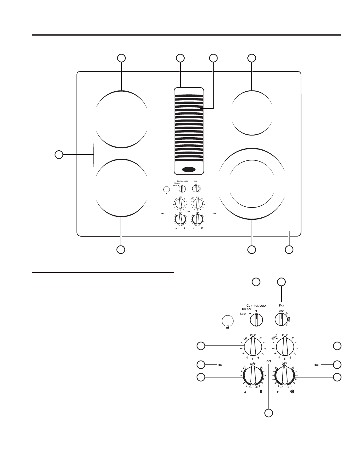
Cooktop Features
/HIW5HDU6XUIDFH8QLW
%ULGJH6XUIDFH8QLW
/HIW)URQW6XUIDFH8QLW
4. Vent Grille
5. Vent Filter (below the vent grille)
5LJKW5HDU6XUIDFH8QLW
'XDO6XUIDFH8QLW
8. Model and Serial Number Label (under the cooktop)
/HIW5HDU6XUIDFH8QLW&RQWURO
/HIW)URQW6XUIDFH8QLW&RQWURO
11. Left Side Hot Surface Indicator Lights
(one for each surface unit)
12. Vent Fan Speed Control
13. Control Lock Knob
14. Right Side Hot Surface Indicator Lights
(one for each surface unit)
'XDO6XUIDFH8QLW&RQWURO
5LJKW5HDU6XUIDFH8QLW&RQWURO
6XUIDFH8QLW2Q,QGLFDWRU/LJKW
Throughout this manual, features and appearance may vary from your model.
Feature Index (Features and appearance may vary)
4516
378
2
9
13
17
12
11
10 15
16
14
49-2001160 Rev. 0 7
Surface Burners
USING THE COOKTOP: 6XUIDFH%XUQHUV
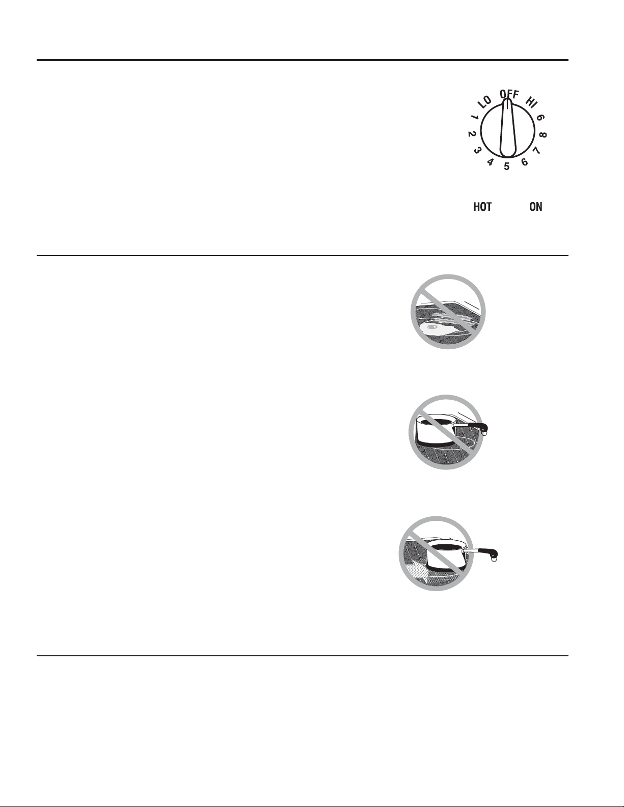
Radiant Surface Units
The control for the radiant surface unit can be set
anywhere between LO and HI for an unlimited number
of heat settings. With the infinite switch the surface
unit cycles on and off to maintain your selected control
setting.
To bring liquids to a boil faster, use a lid to cover the pan.
The control knob must be pushed down and turned
from the OFF position. When the control knobs are in
any position other than off, they may be turned without
pushing down.
%HVXUH\RXWXUQWKHFRQWURONQRERIIZKHQ\RXILQLVK
cooking. You will feel a click at the OFF position.
The surface unit ON indicator
light will glow when any
surface unit is on.
The HOT surface indicator
light will glow when the glass
surface is hot and will remain
on until the surface has cooled.
Home Canning Tips
%HVXUHWKHFDQQHULVFHQWHUHGRYHUWKHVXUIDFHXQLW
Make sure the carrier is flat on the bottom.
To prevent burns from steam or heat, use caution when
canning.
8VHUHFLSHVDQGSURFHGXUHVIURPUHSXWDEOHVRXUFHV
7KHVHDUHDYDLODEOHIURPPDQXIDFWXUHUVVXFKDV%DOO
®
and Kerr
®
DQGWKH'HSDUWPHQWRI$JULFXOWXUH([WHQVLRQ
Service.
)ODWERWWRPHGFDQQHUVDUHUHFRPPHQGHG8VHRIZDWHU
bath canners with rippled bottoms may extend the time
required to bring the water to a boil.
About the radiant surface units
The radiant cooktop features heating units beneath a
smooth glass surface.
NOTE: A slight odor is normal when a new cooktop is
used for the first time. It is caused by the heating of new
parts and insulating materials and will disappear in a
short time.
The cooktop has Rapid Response surface units. The
cooktop will automatically heat up or cool down to
desired power level setting in the quickest time possible.
While the surface units are on, you may not see them
glow red during certain heat up or cool down conditions.
Cooktop temperatures increase with the number of
surface units that are on. With 3 or 4 units turned on,
surface temperatures are high. Always use caution when
touching the cooktop.
Even after the surface units are turned off, the glass
cooktop retains enough heat to continue cooking. To
avoid over-cooking, remove pans from the surface units
when the food is cooked. Avoid placing anything on the
surface unit until it has cooled completely.
Ŷ :DWHUVWDLQVPLQHUDOGHSRVLWVDUHUHPRYDEOHXVLQJ
the cleaning cream or full strength white vinegar.
Ŷ 8VHRIZLQGRZFOHDQHUPD\OHDYHDQLULGHVFHQWILOP
on the cooktop. The cleaning cream will remove this
discoloration.
Ŷ 'RQ¶WVWRUHKHDY\LWHPVDERYHWKHFRRNWRS,IWKH\
drop onto the cooktop, they can cause damage.
Ŷ 'RQRWXVHWKHVXUIDFHDVDFXWWLQJERDUG
Never cook directly on the glass.
Always use cookware.
Always place the pan in the center of
the surface unit you are cooking on.
'RQRWVOLGHFRRNZDUHDFURVVWKH
cooktop because it can scratch
the glass. The glass is scratch-
resistant, not scratchproof.
%HVXUH\RXWXUQWKHFRQWURONQRE
to OFF when you finish cooking.
SURFACE
COOKING
OFF CENTER
DRAGGING
8 49-2001160 Rev. 0
Surface Burners (Cont.)
USING THE COOKTOP:6XUIDFH%XUQHUV
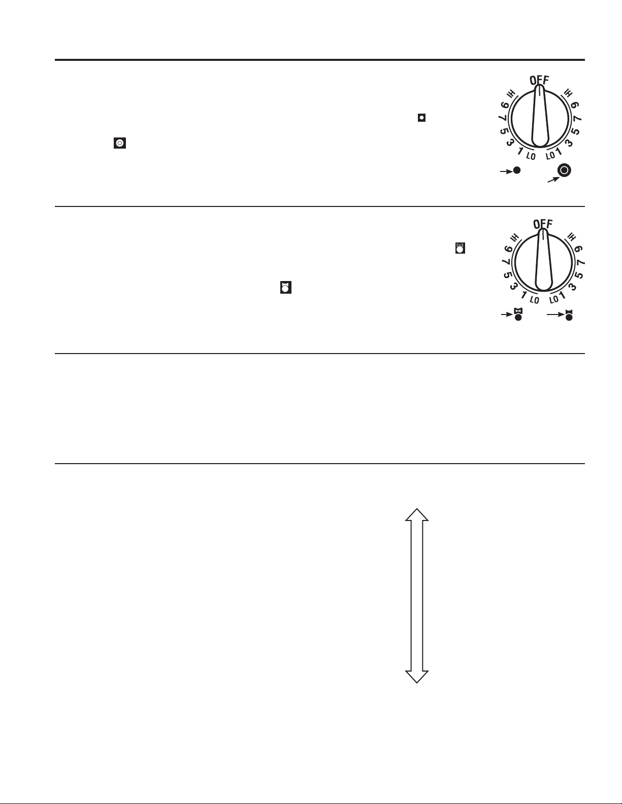
Dual Surface Unit
The right front surface unit has 2 cooking sizes to select
from so you can match the size of the unit to the size of
the cookware you are using.
To use the large (9-inch) surface unit, turn the knob
clockwise to
and select the desired setting. The unit
will heat the entire area contained by the larger circle.
To use the small (6-inch)
surface unit, turn the knob
counterclockwise to and
select the desired setting. The
unit will only heat the area
inside the smaller circle.
Bridge Surface Unit
Make sure the pan rests flat on the glass cooktop and
it is not resting on the trim. If you notice poor cooking
performance, move the pan to make sure it is flat on
the cooktop.
To use the bridge burner, turn the burner knob to and
select the desired setting. The unit will heat the front
surface burner and the bridge.
Choose pans that match the circle/bridge area as closely
as possible.
To use only the front surface
unit, turn the burner knob to
and select the desired setting.
The unit will only heat the front
surface burner.
You can create an oblong
heated area by using the left
rear unit in addition to the front
unit bridge combination.
Surface Elements Cycle On and Off
Surface elements will cycle on and off to maintain the
temperature you have selected.
All radiant surface elements have a temperature limiter
that protects the glass cooktop from getting too hot.
The temperature limiter may cycle the elements off
while cooking if:
Ŷ 7KHSDQERLOVGU\
Ŷ 7KHSDQERWWRPLVQRWIODW
Ŷ 7KHSDQLVRIIFHQWHU
Ŷ 7KHUHLVQRSDQRQWKHHOHPHQW
Selecting Cooktop Settings
Choose the element/burner that is the best fit to the
cookware size. Each element/burner on your new
cooktop has its own power levels ranging from low to
high. Power level settings necessary for cooking will
vary depending on the cookware being used, the type
and quantitiy of the food, and the desired outcome.
In general:
Ŷ
8VHORZHUVHWWLQJVIRUPHOWLQJKROGLQJDQG
simmering.
Ŷ
8VHKLJKHUVHWWLQJVIRUKHDWLQJTXLFNO\VHDULQJDQG
frying.
When keeping foods warm, confirm selected setting is
sufficient to maintain food temperature above 140°F.
Larger elements are not recommended for melting.
Power boil elements are best suited for boiling water,
particularly with pots that are 9" or larger.
Small 6"
surface unit
setting
Large 9"
surface unit setting
Front
%XUQHUDQG
%ULGJH
Front
%XUQHU
only
Hi
boiling quickly
frying
searing
reducing
simmering
holding
melting
Low
49-2001160 Rev. 0 9
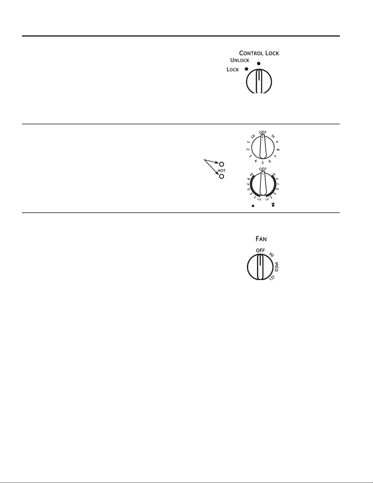
Control Lock-Out for Surface Units
To activate control lock-out, turn the Control Lock knob
to LOCK. This will prevent surface units from heating.
An indicator light will glow to show that they are locked.
The downdraft fan will remain operable with control
lockout engaged.
In the locked position, the cooktop will produce an
audible sound if any surface unit control knob is engaged
or moved to a position other than OFF.
USING THE COOKTOP:6XUIDFH%XUQHUV
Surface Burners (Cont.)
Hot Light Indicator
A hot surface indicator light (one for each cooking
element) will glow when the glass surface is hot
and will remain on until the surface has cooled to
temperature that is safe to touch.
How to Operate the Vent System
The built-in vent system helps remove cooking vapors,
odors and smoke from foods prepared on the cooktop.
To operate the downdraft vent system, turn the vent
IDQVSHHGFRQWURONQREWR+,0('RU/2DVQHHGHG
Continuous use of the vent system while cooking helps
keep the kitchen comfortable and less humid, reducing
cooking odors and soiling moisture that normally
creates a frequent need for cleaning.
Hot surface
indicator lights
10 49-2001160 Rev. 0
Cookware for Radiant Glass Cooktop
NOTE: Follow all cookware manufacturer’s recommendations when using any type of cookware
on the ceramic cooktop.
The following information will help you choose cookware which will give good performance on
glass cooktops.
Stainless Steel:
Recommended.
Aluminum:
Heavy weight recommended.
Good conductivity. Aluminum residues sometimes
appear as scratches on the cooktop but can be removed
LIFOHDQHGLPPHGLDWHO\%HFDXVHRILWVORZPHOWLQJSRLQW
thin weight aluminum should not be used.
Copper Bottom:
Recommended.
Copper may leave residues which can appear as
scratches. The residues can be removed, as long as
the cooktop is cleaned immediately. However, do not let
these pots boil dry. Overheated metal can bond to glass
cooktops. An overheated copper bottom pot will leave
a residue that will permanently stain the cooktop if not
removed immediately.
Porcelain Enamel on Cast Iron:
Recommended if bottom of pan is coated.
Porcelain Enamel on
Steel:
Not recommended.
Heating empty pans can cause
permanent damage to cooktop
glass. The enamel can melt and
bond to the ceramic cooktop.
Glass-ceramic:
Not recommended.
Poor performance. Will scratch
the surface.
Stoneware:
Not recommended.
Poor performance. May scratch
the surface.
Cast Iron:
Not recommended—unless
designed specifically for glass
cooktops.
Poor conductivity and slow to
absorb heat. Will scratch the
cooktop surface.
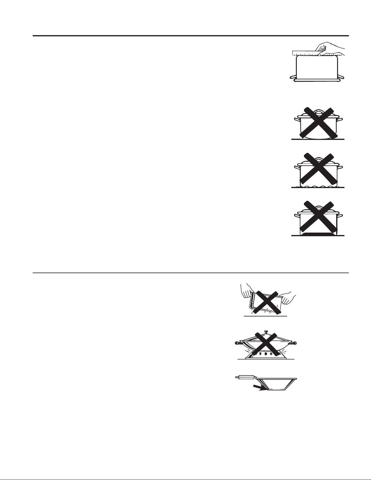
Check pans for flat bottoms
by using a straight edge.
Pans with rounded, curved,
ridged or warped bottoms
are not recommended.
USING THE COOKTOP: Cookware for Radiant Glass Cooktop
For Best Results
Ŷ 3ODFHRQO\GU\SDQVRQWKHVXUIDFHHOHPHQWV'RQRW
place lids on the surface elements, particularly wet lids.
Ŷ 'RQRWXVHZRNVWKDWKDYHVXSSRUWULQJV7KLVW\SHRI
wok will not heat on glass surface elements.
Ŷ We recommend that you use only a flat-bottomed
wok. They are available at your local retail store. The
bottom of the wok should have the same diameter as
the surface element to ensure proper contact.
Ŷ Some special cooking procedures require specific
cookware such as pressure cookers, deep-fat fryers,
etc. All cookware must have flat bottoms and be the
correct size.
Ŷ Avoid allowing foods to boil dry as some cookware
may stick to the cooking surface, causing permanent
damage to the cooktop.
'RQRWSODFHZHWSDQVRQ
the glass cooktop.
'RQRWXVHZRNVZLWKVXSSRUW
rings on the glass cooktop.
8VHIODWERWWRPHGZRNVRQ
the glass cooktop.
49-2001160 Rev. 0 11
Cleaning the Cooktop
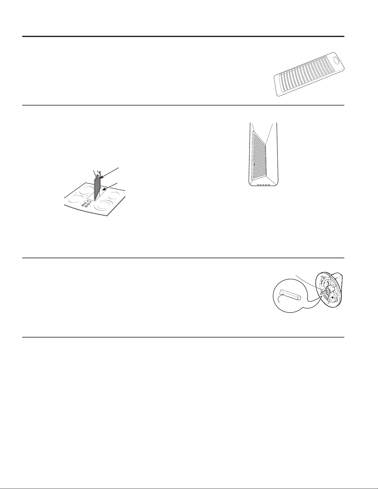
Vent Grille
%HIRUHFOHDQLQJWKHYHQWJULOOHEHVXUHWKHH[KDXVW
blower is turned off.
To clean the vent grille, remove it from the cooktop by
lifting it up and off. Wipe with a damp cloth. If necessary,
the vent grille can be washed in the sink.
8VHGLVKZDVKLQJOLTXLGIRUFOHDQLQJ
'RQRWXVHDEUDVLYHFOHDQHUV
They will damage the vent
grille’s finish.
'RQRWFOHDQWKHYHQWJULOOHLQ
the dishwasher.
Vent Filter and Chamber
The filter is held in place at an angle with a hold bump.
Lift the filter up and out of the vent opening diagonally.
To clean the filter, swish it in hot, soapy water. Rinse
well and dry thoroughly.
Do not operate the vent without the filter in place.
To clean the vent chamber, use hot, soapy water. Rinse
ZLWKFOHDQZDWHUDQGGU\WKRURXJKO\'RQRWXVHDEUDVLYH
cleaners; they will damage the finish. Replace the filter
after it is cleaned and dry.
Remove and replace the filter diagonally
through the vent opening.
To order replacement filters, see the
Accessories section.
Vent
Chamber
Vent Filter
When replacing the filter, make sure
it rests, at an angle, on the supports
in the vent opening.
Control Knobs
The control knobs may be removed for easier cleaning.
Make sure the knobs are in the Off positions and pull
them straight off the stems for cleaning.
To clean the knobs, place them in a dishwasher or wash
with soap and water. Rinse with clean water. Make sure
the insides of knobs are dry before replacing.
Replace the knobs in the Off
position to ensure proper
placement.
Stainless Steel Surfaces (on some models)
'RQRWXVHDVWHHOZRROSDGLWZLOOVFUDWFKWKHVXUIDFH
To clean the stainless steel surface, use warm sudsy
water or a stainless steel cleaner or polish. Always wipe
the surface in the direction of the grain. Follow the cleaner
instructions for cleaning the stainless steel surface.
To inquire about purchasing cleaning products including
stainless steel appliance cleaner or polish, see the
Accessories section.
CARE AND CLEANING: Cleaning the Cooktop
Flat
Molded flat area
The control knobs may be
removed for easier cleaning.
12 49-2001160 Rev. 0
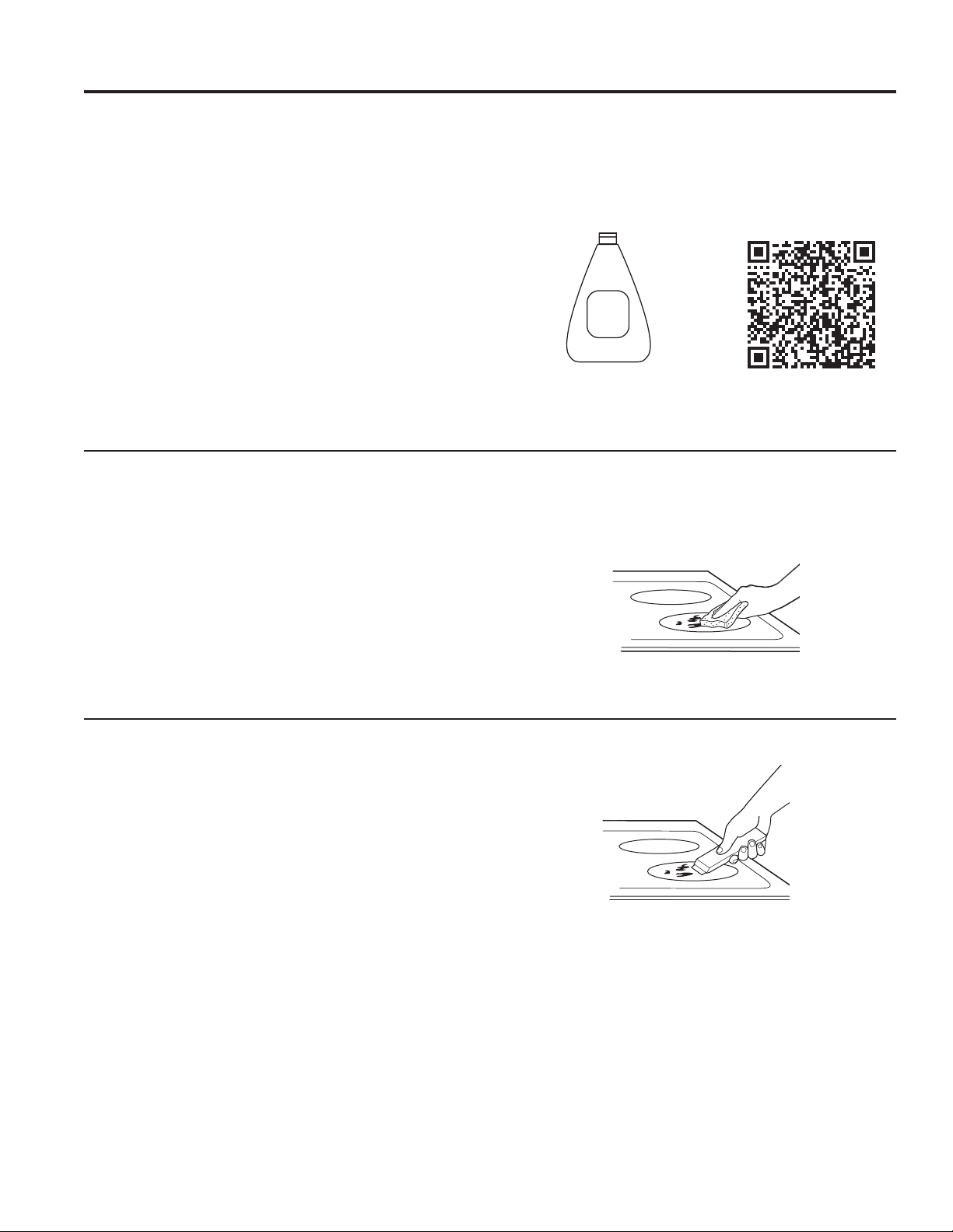
Cleaning the Glass Cooktop
Glass Cooktop
To maintain and protect the surface of your glass
cooktop, follow these steps:
%HIRUHXVLQJWKHFRRNWRSIRUWKHILUVWWLPHFOHDQLW
with a ceramic glass cooktop cleaner. This helps
protect the top and makes cleanup easier.
2. Regular use of a ceramic glass cooktop cleaner will
help keep the cooktop looking new.
3. Shake the cleaning cream well. Apply a few drops
of a ceramic glass cooktop cleaner directly to the
cooktop.
8VHDSDSHUWRZHORUDQRQVFUDWFKFOHDQLQJSDGIRU
ceramic glass cooktops to clean the entire cooktop
surface.
8VHDGU\FORWKRUSDSHUWRZHOWRUHPRYHDOOFOHDQLQJ
residue. No need to rinse.
NOTE: ,WLVYHU\LPSRUWDQWWKDW\RX'2127KHDWWKH
cooktop until it has been cleaned thoroughly.
Clean your cooktop after each
VSLOO8VHDFHUDPLFJODVV
cooktop cleaner.
Ceramic
Cooktop
Cleaner
For cleaning videos and
instructions, scan the QR code
with your device.
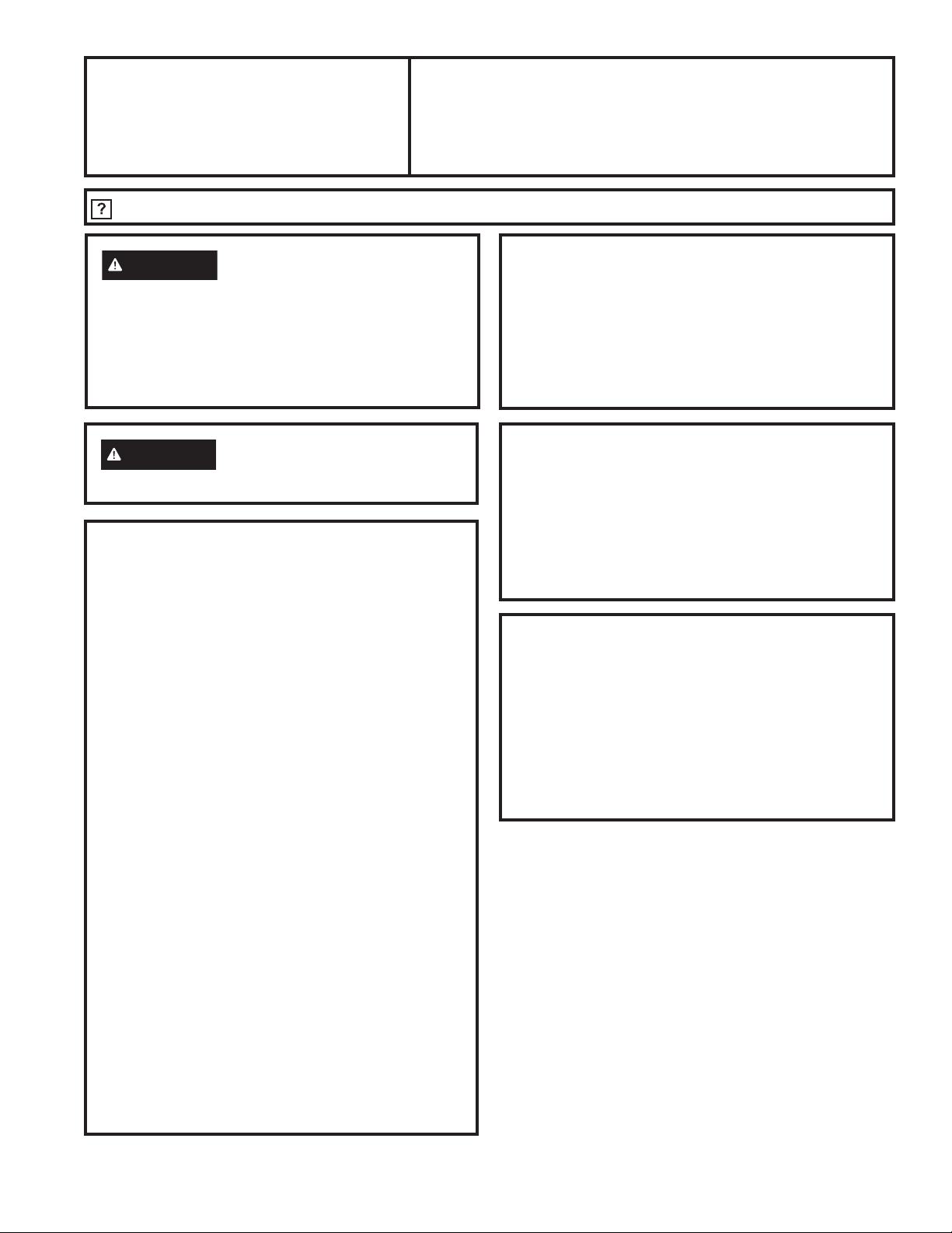
Burned-On Residue
NOTE:'$0$*(WR\RXUJODVVVXUIDFHPD\RFFXULI\RX
use scrub pads other than those recommended.
1. Allow the cooktop to cool.
2. Spread a few drops of a ceramic glass cooktop
cleaner on the entire burned residue area.
8VLQJDQRQVFUDWFKFOHDQLQJSDGIRUFHUDPLFJODVV
cooktops, rub the residue area, applying pressure as
needed.
4. If any residue remains, repeat the steps listed above
as needed.
5. For additional protection, after all residue has been
removed, polish the entire surface with a ceramic
cooktop cleaner and a paper towel.
8VHDQRQVFUDWFKFOHDQLQJSDGIRU
ceramic glass cooktops.
Heavy, Burned-On Residue
1. Allow the cooktop to cool.
8VHDVLQJOHHGJHUD]RUEODGHVFUDSHUDWDSSUR[LPDWHO\
a 45° angle against the glass surface and scrape the
soil. It will be necessary to apply pressure to the razor
scraper in order to remove the residue.
3. After scraping with the razor scraper, spread a few drops
of a ceramic glass cooktop cleaner on the entire burned
UHVLGXHDUHD8VHDQRQVFUDWFKFOHDQLQJSDGWRUHPRYH
any remaining residue.
4. For additional protection, after all residue has been
removed, polish the entire surface with a ceramic
glass cooktop cleaner and a paper towel.
The ceramic glass cooktop scraper and all recommended
supplies are available through our Parts Center. See
Accessories and Consumer Support sections.
NOTE:'RQRWXVHDGXOORUQLFNHGEODGH
CARE AND CLEANING: Cleaning the Glass Cooktop

49-2001160 Rev. 0 13
CARE AND CLEANING: Cleaning the Glass Cooktop
Cleaning the Glass Cooktop (Cont.)
Metal Marks and Scratches
%HFDUHIXOQRWWRVOLGHSRWVDQGSDQVDFURVV\RXU
cooktop. It will leave metal markings on the cooktop
surface.
These marks are removable using a ceramic cooktop
cleaner with a non-scratch cleaning pad for ceramic
cooktops.
2. If pots with a thin overlay of aluminum or copper
are allowed to boil dry, the overlay may leave black
discoloration on the cooktop.
This should be removed immediately before heating
again or the discoloration may be permanent.
NOTE: Carefully check the bottom of pans for roughness
that would scratch the cooktop.
%HFDUHIXOQRWWRSODFHDOXPLQXPEDNLQJVKHHWVRU
aluminum frozen entrée containers on a hot cooktop
surface. It will leave shiny dots or markings on the
cooktop surface. These markings are permanent and
cannot be cleaned off.
Damage from Sugary Spills and Melted Plastic
Special care should be taken when removing hot substances to avoid permanent damage of the glass surface.
Sugary spillovers (such as jellies, fudge, candy, syrups) or melted plastics can cause pitting of the surface of your
cooktop (not covered by the warranty) unless the spill is removed while still hot. Special care should be taken when
removing hot substances.
%HVXUHWRXVHDQHZVKDUSUD]RUVFUDSHU
'RQRWXVHDGXOORUQLFNHGEODGH
1. Turn off all surface units. Remove hot pans.
2. Wearing an oven mitt:
D8VHDVLQJOHHGJHUD]RUEODGHVFUDSHUWRPRYH
the spill to a cool area on the cooktop.
b. Remove the spill with paper towels.
3. Any remaining spillover should be left until the surface
of the cooktop has cooled.
'RQ¶WXVHWKHVXUIDFHXQLWVDJDLQXQWLODOORIWKH
residue has been completely removed.
NOTE: If pitting or indentation in the glass surface has
already occurred, the cooktop glass will have to be
replaced. In this case, service will be necessary.
14 49-2001160 Rev. 0
If you have questions, call 800.GE.CARES or visit our website at: GEAppliances.com.
Installation
Radiant Downdraft Cooktop
Instructions
PP9830
WARNING
%HIRUHEHJLQQLQJWKHLQVWDOODWLRQ
switch power off at the service panel and lock the
service disconnecting means to prevent power from
being switched on accidentally. When the service
disconnecting means cannot be locked, securely
fasten a prominent warning device, such as a tag,
to the service panel.
WARNING
To reduce the risk of fire, use only
metal ductwork.
BEFORE YOU BEGIN
Read these instructions completely and
carefully.
• IMPORTANT
–
Save these
instructions for local inspector’s use.
•
IMPORTANT
–
Observe all governing
codes and ordinances.
•
IMPORTANT
–
Remove all packing
and material and literature before connecting gas
and electrical supply to cooktop.
•
IMPORTANT
–
To avoid damage to
your cabinets, check with your builder or cabinet
supplier to make sure that the materials used will
not discolor, delaminate or sustain other damage.
This product has been designed in accordance
ZLWKWKHUHTXLUHPHQWVRI8/DQG&6$,QWHUQDWLRQDO
and complies with the maximum allowable wood
cabinet temperatures of 194°F (90°C).
• Note to Installer –%HVXUHWROHDYHWKHVH
instructions with the Consumer.
• Note to Consumer – Keep these instructions for
future reference.
• Servicer – The electrical diagram is located inside
the cooktop.
• Proper installation is the responsibility of the
installer.
• Product failure due to improper installation is not
covered under the Warranty.
CUTTING THE COUNTERTOP
If you are installing the cooktop in a solid surface
material such as granite, quartz or any other natural
or synthetic solid surface, we recommend that the
cutout be prepared by a professional cabinet or
coutertop installer.
Cooktop cutouts in wood or wood -laminate
countertops may be able to be prepared using a
saber saw and electric drill.
MATERIALS YOU MAY NEED
'XFWWDSH
• Sheet metal screws
'XFWZRUNWRVXLWWKHDSSOLFDWLRQ
• Junction box
• Strain relief clamp for 1/2" trade size conduit
• Wire nuts
TOOLS YOU WILL NEED
• Safety Glasses
• Saw
• Pencil
• Measuring tape
or scale
• Carpenter’s square
• Electrician's Pliers
• Adjustable wrench
or socket set (
7
/16”
socket and ratchet)
• 'ULOODQGGULOOELW
•
1
/4” nut driver
• Flat blade screwdriver
INSTALLATION INSTRUCTIONS
49-2001160 Rev. 0 15
INSTALLATION INSTRUCTIONS
Installation Instructions
IMPORTANT SAFETY INSTRUCTIONS
The cooktop has been design certified by
8QGHUZULWHUV/DERUDWRULHV8/$VZLWKDQ\
appliance generating heat, there are certain safety
precautions you should follow.
• %HVXUH\RXUFRRNWRSLVLQVWDOOHGSURSHUO\E\D
qualified installer or service technician.
• The cooktop must be electrically grounded in
accordance with local codes, or in their absence,
with the National Electrical Code ANSI/NFPA No.
70 or the Canadian Electric Code, CSA C22.1-02.
• Improper installation, adjustment, alteration,
service or maintenance can cause injury or
property damage. Refer to this manual. For
assistance or additional information, consult a
qualified installer, service agency, manufacturer
(dealer) or the gas supplier.
• 'LVFRQQHFWHOHFWULFDOVXSSO\EHIRUHVHUYLFLQJ
• To eliminate the risk of burns due to reaching over
heated surface elements, cabinet storage located
above the surface units should be avoided. If
cabinet storage space is to be provided, the risk
can be reduced by installing a range hood that
projects horizontally a minimum of 5" beyond the
bottom of the cabinets. Cabinet installation above
a cooktop may be no deeper than 13".
• Make sure the wall coverings around the cooktop
can withstand heat generated by the cooktop up to
200°F.
• If a 30" clearance between cooking surface and
overhead combustible material or metal cabinets
cannot be maintained, protect the underside of the
cabinets above the cooktop with not less than
1
/4"
insulating millboard or gypsum board at least
3
/16"
thick covered with 28 gauge sheet steel or 0.020"
thick copper.
• Clearance between the cooking surface and
protected cabinets MUST NEVER BE LESS
THAN 24” The vertical distance from the plane
of the cooking surface to the bottom of adjacent
overhead cabinets extending closer than 1" to the
plane of the cooktop sides must not be less than
18”.
• When cutting or drilling into wall or ceiling, do not
damage electrical wiring and other hidden utilities.
• 'XFWHGIDQVPXVWDOZD\VEHYHQWHGWRWKH
outdoors.
WARNING
EXHAUST BLOWER
SAFETY WARNING
Sufficient air is needed for proper combustion and
exhausting of gases through the flue (chimney) of
fuel burning equipment to prevent back drafting.
Follow the heating equipment manufacturer’s guide
lines and safety standards, such as those published
by the National Fire Protection Association (NFPA),
the American Society for Heating, Refrigeration
and Air Conditioning (ASHRAE) and the local code
authorities. when applicable, install any make up
(replacement) air system in accordance with local
building code requirements. Visit GEAppliances.com
for available makeup air solutions.
ELECTRICAL REQUIREMENTS
This appliance must be supplied with the proper
voltage and frequency, as listed in these Installation
Instructions, and connected to an individual,
properly grounded branch circuit, protected by a
40-amp circuit breaker or time delay fuses.
All wire connections must be made in accordance
with local codes and properly insulated. Check
with your local utility for governing electrical codes
and ordinances. In the absence of local electrical
codes, the National Electrical Code, ANSI/NFPA
No. 70 – Latest Edition, governing electric range
installations, must be followed.
A copy of the National Electrical Code can be
obtained by writing to:
National Fire Protection Association
%DWWHU\PDUFK3DUN
Quincy, MA 02260
Effective January 1, 1996, the National Electrical
Code requires that new, but not existing,
construction utilize a four-conductor connection to
an electric range. When installing an electric range
in new construction, follow the instructions in NEW
&216758&7,21$1')285&21'8&725
%5$1&+&,5&8,7&211(&7,21
You must use a three-wire, single-phase AC
208Y/120 Volt or 240/120 Volt, 60 Hertz electrical
system with separate ground. If you connect to
aluminum wiring, properly installed connectors
approved for use with aluminum wiring must be
used.
16 49-2001160 Rev. 0
Installation Instructions
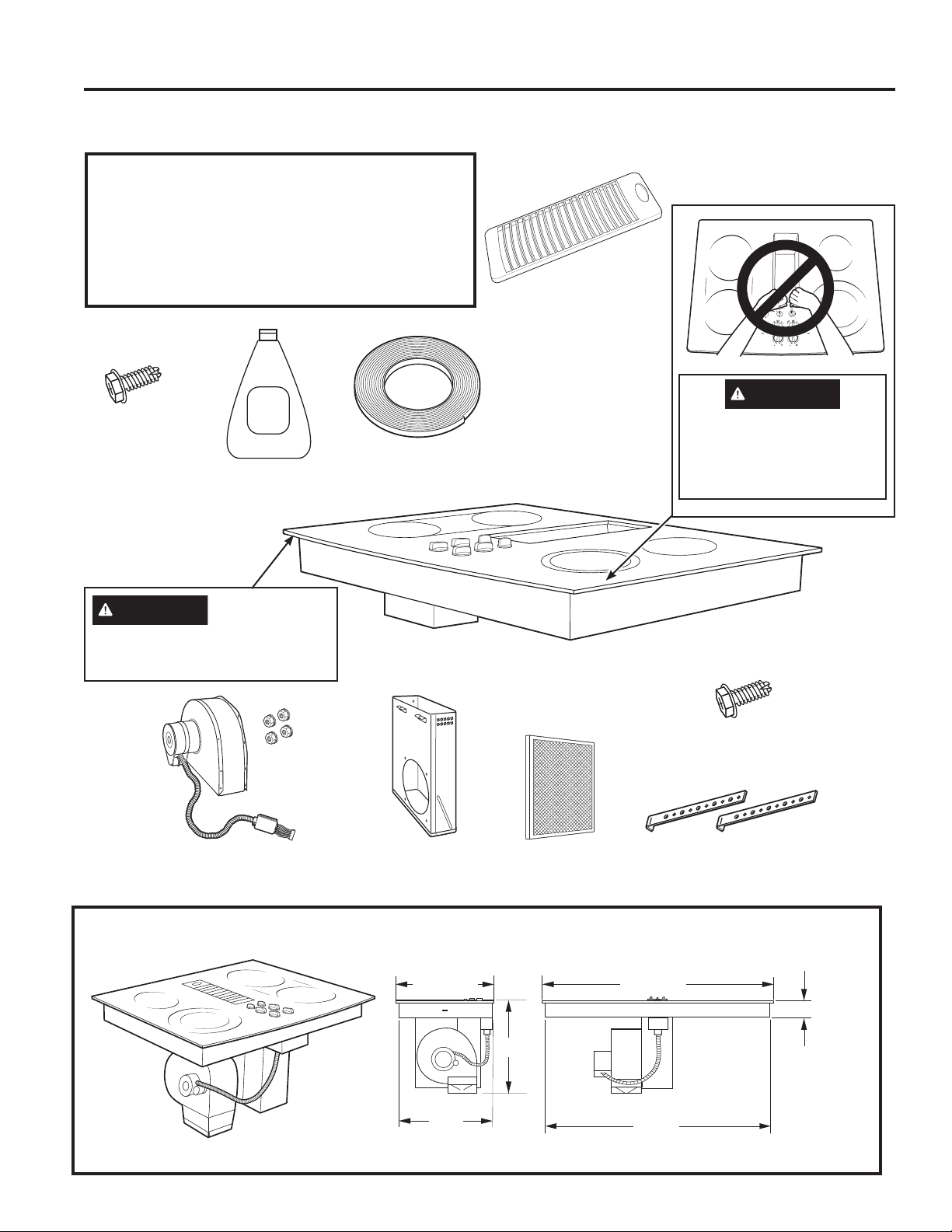
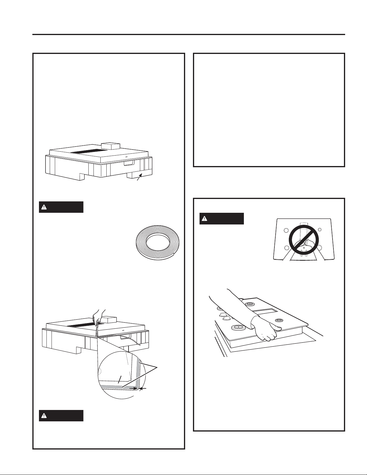
UNPACKING YOUR COOKTOP
CAUTION
'2127/,)7
FROM VENT OPENING OR
%803*/$66
Check to be sure that all packing materials
and tape have been removed. This will include
tape on control knobs (if applicable), adhesive
tape, wire ties, cardboard and protective plastic.
Failure to remove these materials could result
in damage to the appliance once the appliance
has been turned on and surfaces have heated.
INSTALLATION INSTRUCTIONS
Vent Grille
Cleaning Cream
Sheet Metal
Screws (9)
(8-18 x 3/8")
Foam Gasket Tape
%ORZHU$VVHPEO\DQG0RXQWLQJ
Nuts (10-32 keps – nuts with lock
washers attached)
%ORZHU
Plenum
Vent
Filter
Ceramic
Cooktop
Cleaner
CAUTION
GLASS IS FRAGILE
DO NOT BUMP EDGE
OF GLASS DURING
INSTALLATION
Sheet Metal
Screws (2)
(10-16 x 1/2”)
+ROG'RZQ
%UDFNHWV
30" COOKTOP (DIMENSIONS FOR REFERENCE ONLY)
Unit shown fully assembled.
Unit must be vented to the outside!
20
1
»2”
22”
28
3
»4”
2
1
»2”
(2
9
»16” SS)
21
7
»8”
(21
15
»16” SS)
29
3
»4”
(29
13
»16” SS)
49-2001160 Rev. 0 17
INSTALLATION INSTRUCTIONS
Installation Instructions
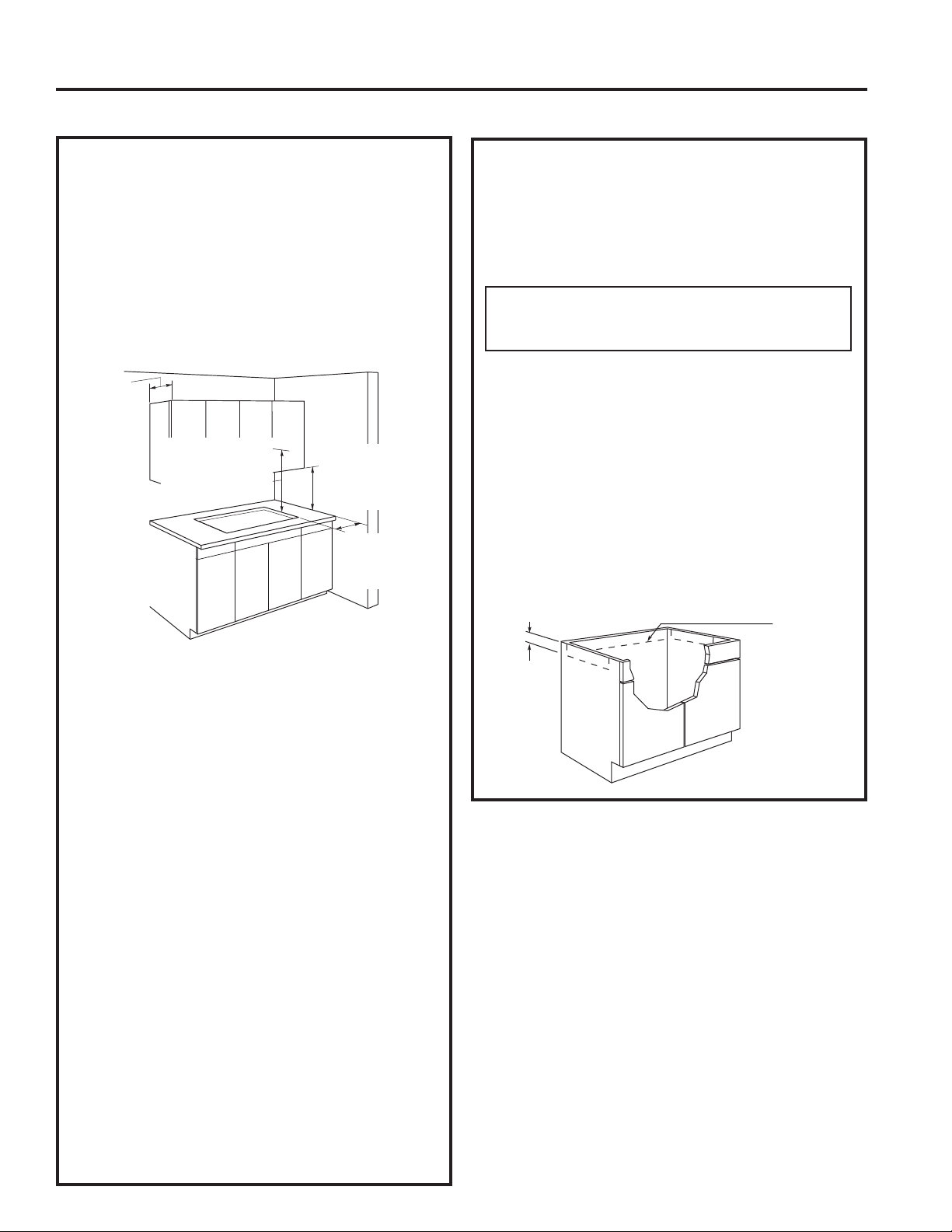
INSTALLATION PREPARATION
1. PREPARING FOR INSTALLATION
Positioning the cooktop
The cooktop is designed to look best when centered
in a cabinet at least 30" wide.
The exhaust vent beneath the cooktop must be
located between wall studs or floor joists so that the
ductwork may be installed properly.
At least 5 1/2” must be allowed between side edges
of the cooktop and adjacent walls.
Avoid placing cabinets above the cooktop unit, if
possible, in order to reduce the hazards caused by
reaching over heated surface units. If cabinets are
placed over the cooktop, the risks can be reduced
by installing a range hood that projects horizontally
a minimum of 5 inches beyond the bottom of the
cabinets.
If the cabinetry is used above the cooktop, allow
a minimum 30" clearance between the cooking
surface and the bottom of the unprotected cabinet.
If the clearance between the cooktop and the
cabinetry is less than 30", the cabinet bottom must
be protected with a flame retardant millboard at least
1
/4" thick, or gypsum board at least
3
/16" thick, covered
with 28 gauge sheet steel or 0.020" thick copper.
Clearance between the cooktop and the protected
cabinetry MUST NEVER BE LESS THAN 24".
EXCEPTION: Installation of a listed microwave
oven or cooking appliance over the cooktop shall
conform to the installation instructions packed with
that appliance.
Working areas adjacent to the cooktop should have
an
15" minimum clearance between the countertop and the
bottom of the cabinet. If the clearance is less than 15”, the
adjacent cabinets should be at least 5 1/2” from the side
edge of the cooktop
2. PREPARING THE BASE CABINET
This cooktop is designed to fit easily into a variety
of cabinets. However, the combined installation
of a downdraft vent and a cooktop require careful
consideration.
Some cabinets may require modifications.
This installation requires a 24” min. deep
cabinet base.
The cabinet must be at least 30” wide.
Preparing a cabinet that is against a wall
In some cabinets, the sides may need to be
VFRRSHGRUFXWGRZQ»´DVVKRZQDQGWKH
corner braces removed in order to accommodate
the unit.
In 75 cm and 90 cm frameless European cabinets,
WKHEDFNSDQHOPD\QHHGWREHFXWGRZQ»´WR
accommodate the unit.
Preparing a peninsula or island-type cabinet
In a peninsula or island type cabinet, the sides may
need to be scooped or cut down, and the corner
braces removed in order to accommodate the unit.
13" max.
depth of
unprotected
overhead
cabinets
6" min.
clearance from
cutout to side
walls
30" min. clearance
from countertop
to unprotected
overhead surface
15" min. height
from countertop to
nearest cabinet on
either side of the
unit
5
3
»4
”
Approx.
5
3
»4
”
Approx.
for European
cabinets
18 49-2001160 Rev. 0
Installation Instructions
INSTALLATION PREPARATION (Cont.)
5. PREPARING FOR DUCTWORK
VENTING
NOTE: 'XFWZRUN0867EHYHQWHGWRRXWVLGH'2
NOT vent into a wall, ceiling, crawlspace, attic or
any concealed space.
Cut hole in cabinet wall or floor as appropriate for
your installation. Make sure exhaust duct is located
between wall studs or floor joists.
NOTE: When cutting or drilling into wall or ceiling,
do not damage electrical wiring and other hidden
utilities. Make sure that any opening/cutout in the
wall behind the appliance and in the floor under the
appliance are sealed properly.
20 5/8" ±1/8"
1 7/8"min.
25"
28 7/8" ±1/8"
2 3/8"
min.
9
1
»8
”
18
3
»4
”
10
1
»8
”
6
1
»8
”
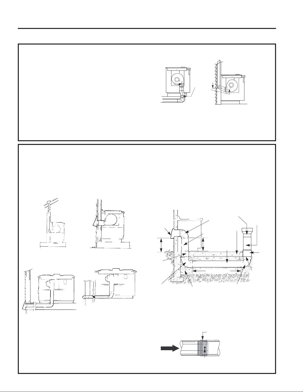
Rear Wall Venting
'RZQZDUG9HQWLQJ
INSTALLATION INSTRUCTIONS
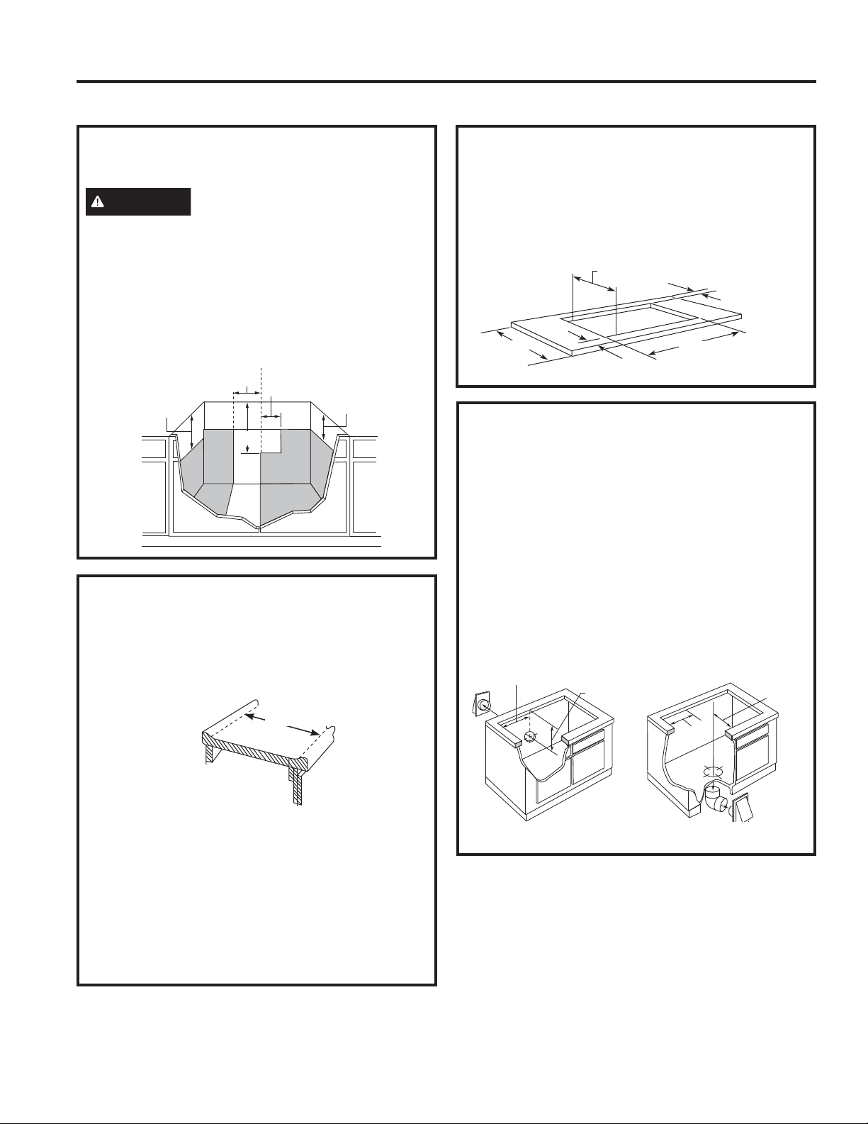
4. PREPARING THE COUNTERTOP
The countertop must have a deep flat surface
to accommodate the cooktop and the vent.
Countertops with a rolled front edge and backsplash
may not provide the flat surface area required.
A 1/2” wide flat area is required around the edge
of opening for support of the unit. The cooktop
unit must be level and sit squarely into countertop
opening.
Carefully cut countertop opening according to the
GLPHQVLRQVVKRZQLQWKHLOOXVWUDWLRQ%HVXUHWKDW
opening is cut squarely, with sides parallel to each
other and rear exactly perpendicular to sides.
4. PREPARING THE COUNTERTOP
(CONT.)
For island installation, maintain 1 7/8” minimum
from cutout to front edge; 2 3/8” minimum from
cutout to back edge; and 6” minimum from cutout to
side edges of countertop.
25” min. flat
surface area
required
3. ROUGH PREPARATION OF
JUNCTION BOX
CAUTION
FOR PERSONAL SAFETY,
REMOVE HOUSE FUSE OR OPEN CIRCUIT
BREAKER BEFORE PREPARING JUNCTION BOX.
Install an approved junction box within shaded area
shown in diagram. Junction box must be at least
»´EHORZWRSRIFDELQHW
Run conductors from residence wiring to junction box
according to local electrical codes.
16"
9"
4"
20”
10
1
»2”
C
L
49-2001160 Rev. 0 19
INSTALLATION INSTRUCTIONS
Installation Instructions
INSTALLATION PREPARATION (Cont.)
7. PREPARE FOR DUCTWORK
'HWHUPLQHWKHEHVWURXWHIRUGXFWZRUNLWFDQEHURXWHG
in a variety of ways depending on the kitchen layout.
IMPORTANT: The downdraft air discharge outlet
IRUWKLVXQLWLV»´[´UHFWDQJXODU3ODQGXFWLQJ
accordingly.
Typical duct arrangement countertop series.
To maximize the ventilation performance of the vent
system:
1. Minimize the duct run length and number of
transitions and elbows.
2. Maintain a constant duct size.
3. Seal all joints with duct tape to prevent any leaks.
'RQRWXVHDQ\W\SHRIIOH[LEOHGXFWLQJ
If needed, install any make up (replacement) air
system in accordance with local building code
requirements. Visit GEAppliances.com for available
makeup air solutions.
• Optional duct arrangement under concrete slab.
PVC duct should be used if installing under a poured
concrete slab.
• Install ductwork so the piece of duct nearest the
downdraft unit slots INTO the next piece of the duct.
Secure the joints with self-tapping screws and apply
duct tape around the joints to ensure an airtight seal.
Inside wall
cabinet
8SLQVLGHZDOOWRURRIRU
overhang
'LUHFWO\WRRXWVLGH
%HWZHHQIORRUMRLVWV Through cabinet toe space
Peninsula or island
Peninsula
Outside
wall cabinet
NOTE: PVC sewer pipe type PSM 12454-B
Schedule 40 ASTM D1785.
Wall Cap
Concrete
Slab
6″ (15 cm)
Dia. PVC
Sewer Pipe
6″ (15 cm)
Dia. Metal
Duct
Pack tightly with gravel
or sand completely
around pipe
3-1/4″ x 10″ Rectangular
to 6″ Round Transition
6″ (15 cm)
Dia. 90°
Metal Elbow
6″ (15 cm) Dia.
Metal Duct
16″
(40.6 cm)
Max.
12″
(30 cm)
Min.
6″
(15 cm)
Dia. PVC
Coupling
6″ (15 cm) Dia.
PVC Sewer Pipe
Elbow
6″ (15 cm) Dia.
PVC Sewer Pipe
Elbow
6″ (15 cm)
Dia. PVC
Sewer
Pipe
6″
(15 cm)
Dia.
PVC
Coupling
30′-0″ (9.14 m) Max.
Duct Tape
Over Seam and Screw
Screw
Air
Flow
6. BLOWER TO DUCTWORK ALIGNMENT
In general, the use of flexible ducting is discouraged
because it can cause severely restricted airflow.
However, if the blower outlet and the floor or wall
duct location do NOT align well, then flexible
METAL ducting can be used to adapt to an offset.
Good alignment without use of flexible ducting is best.
NOTE:
•
'RQRWH[FHHGWKHPD[LPXPUHFRPPHQGHGRIIVHWRI´
'RQRWDOORZWKHIOH[LEOHGXFWLQJWRNLQNRUFROODSVH
'RVWUHWFKWKHIOH[LEOHGXFWLQJDVPXFKDVSRVVLEOH
to eliminate as much of the corrugation as possible.
$»´[´UHFWDQJOHWR´URXQGWUDQVLWLRQGXFWLV
available at your local building supply store.
NOTE: Illustrations are for planning purposes only.
6" Max.
Centerline
to
Centerline
Offset
%DFN9HQWLQJ
(Requires 3
1
»4” x 10")
%RWWRP9HQWLQJ
20 49-2001160 Rev. 0
Installation Instructions
8. INSTALLING THE FOAM
GASKET
'RQRWLQVWDOOWKHFRRNWRSLQWRWKHFRXQWHUWRS
without installing the foam gasket as shown. It
protects the bottom edge of the glass from the
countertop and seals the cooktop against spills.
Remove the cooktop along with its shipping pad
from the shipping box. Remove the shipping block
from the downdraft vent opening and place it under
the shipping pad to provide level support.
CAUTION
*/$66,6)5$*,/('2127
%803('*(2)*/$66'85,1*,167$//$7,21
Locate the foam gasket tape
included with your cooktop.
Smooth rough edges of the cutout.
Peel off the white backing to install
the foam gasket tape on the bottom
side of the cooktop glass.
Foam Gasket Installation Notes:
• The foam gasket tape should be installed within
´RIWKHHGJHRIWKHJODVV'RQRWVWUHWFKRU
twist the foam gasket tape.
CAUTION
Failure to install foam gasket
tape greatly increases the potential of breaking the
cooktop glass when installing, especially in Corian®
or granite countertops.
Center vent shipping block – place
under the shipping pad to provide
level support
INSTALLATION PREPARATION (Cont.)
8. INSTALLING THE FOAM
GASKET (Cont.)
8VHFDUHQRWWRVWUHWFKWKHIRDPJDVNHWWDSHZKLOH
it is installed or it will not stay in place.
'RQRWSODFHIRDPJDVNHWWDSHRYHUWKHPHWDO
flanges.
%XWWKHIRDPJDVNHWWDSHHQGVWRJHWKHUDWHDFK
corner without overlapping.
• Trim the foam gasket tape to length without
stretching.
• Mitre cut outside corners of foam gasket tape
slightly if necessary for appearance.
'RQRWVFUDWFKWKHJODVVZKLOHFXWWLQJWKHIRDP
gasket tape.
8QGHUVLGH
of Glass
Foam
Gasket
Tape
1
»8
”
max. to
Glass Edge
INSTALLATION INSTRUCTIONS
9. INSTALLING THE COOKTOP
CAUTION
'2127/,)7)520
VENT OPENING.
Lift the cooktop by the
glass side edges as
shown.
NOTE: 'RQRWXVHWKH
glass top vent opening to lift or move the cooktop
into position.
Lower the cooktop into the countertop opening,
guiding it into position. Glass is fragile—do not
allow it to drop onto the countertop. Support from
the underside and lower slowly.
Carefully remove your fingers one corner at a time
to lower the cooktop into position.
Once the unit is placed in countertop; visually
inspect the cooktop and counter, appearance or
alignment concerns.
COOKTOP INSTALLATION
49-2001160 Rev. 0 21
INSTALLATION INSTRUCTIONS
Installation Instructions
COOKTOP INSTALLATION
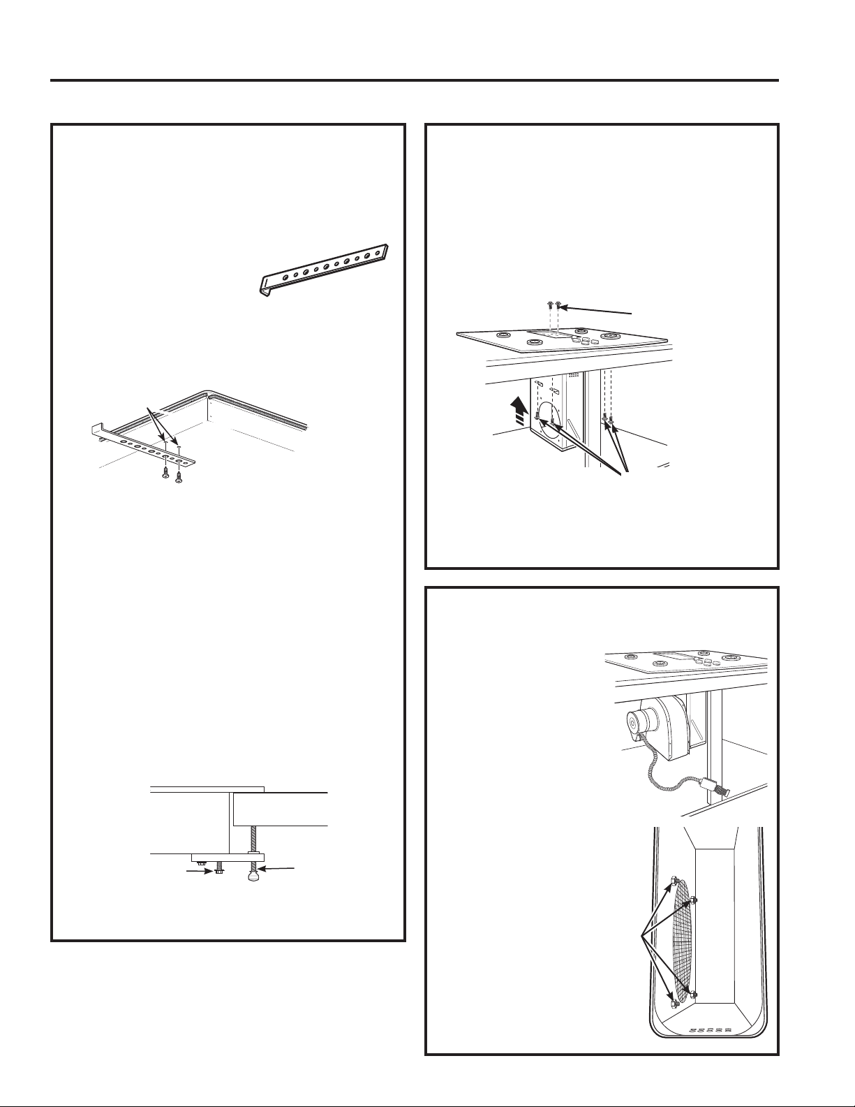
10. INSTALLING THE OPTIONAL
INSTALLATION BRACKETS
A. Make sure the front edge of the countertop is
parallel to the cooktop. Make final check that all
required clearances are met.
%/RFDWHDQGUHPRYH
hold-down brackets from
installation kit package.
C. Attach brackets to the
underside of the cooktop. Remove the screws
from the bottom of the cooktop and screw the
hold-down bracket to the bottom of the cooktop
unit. Repeat for opposite side of cooktop.
'6FUHZWKHKROGGRZQEUDFNHWVLQWRWKHFDELQHW
sides to secure the unit into place.
Alternate Installation:
You can order an alternate installation kit
:%;ZLWKZLQJQXWVDQGEUDFNHWVE\FDOOLQJ
800.GE.CARES. See diagram for instructions.
To install optional installation brackets:
Remove 2 screws on both sides under cooktop.
Align optional installation bracket under cooktop and
UHLQVWDOOVFUHZVWKURXJKWKHVORWLQWKHEUDFNHW'R
this on both sides of the cooktop.
Thread the thumb screw through the hole in the
bracket and tighten to secure the cooktop to the
countertop. Repeat on the other side.
IMPORTANT: Turn the thumbscrew until it touches
WKHERWWRPRIWKHFRXQWHUWRS'RQRWRYHUWLJKWHQ
Cooktop
Countertop
Screws supplied with
cooktop
Thumb screw
Pre-drilled holes
%RWWRPRI
Cooktop
Cooktop Surface
11. INSTALLING THE BLOWER
PLENUM TO THE COOKTOP
Slide the plenum, with the blower opening on the
left, into the opening in the bottom of the cooktop.
Push up on the plenum until the stops on the
plenum contact the bottom of the cooktop, and snap
the plenum into place. (You may have to move the
plenum back and forth to work it into place.)
Secure the plenum to the bottom of the cooktop,
on each side, using the four (4) screws provided.
Further secure the plenum to the cooktop, from the
top side, using the two screws (2) provided.
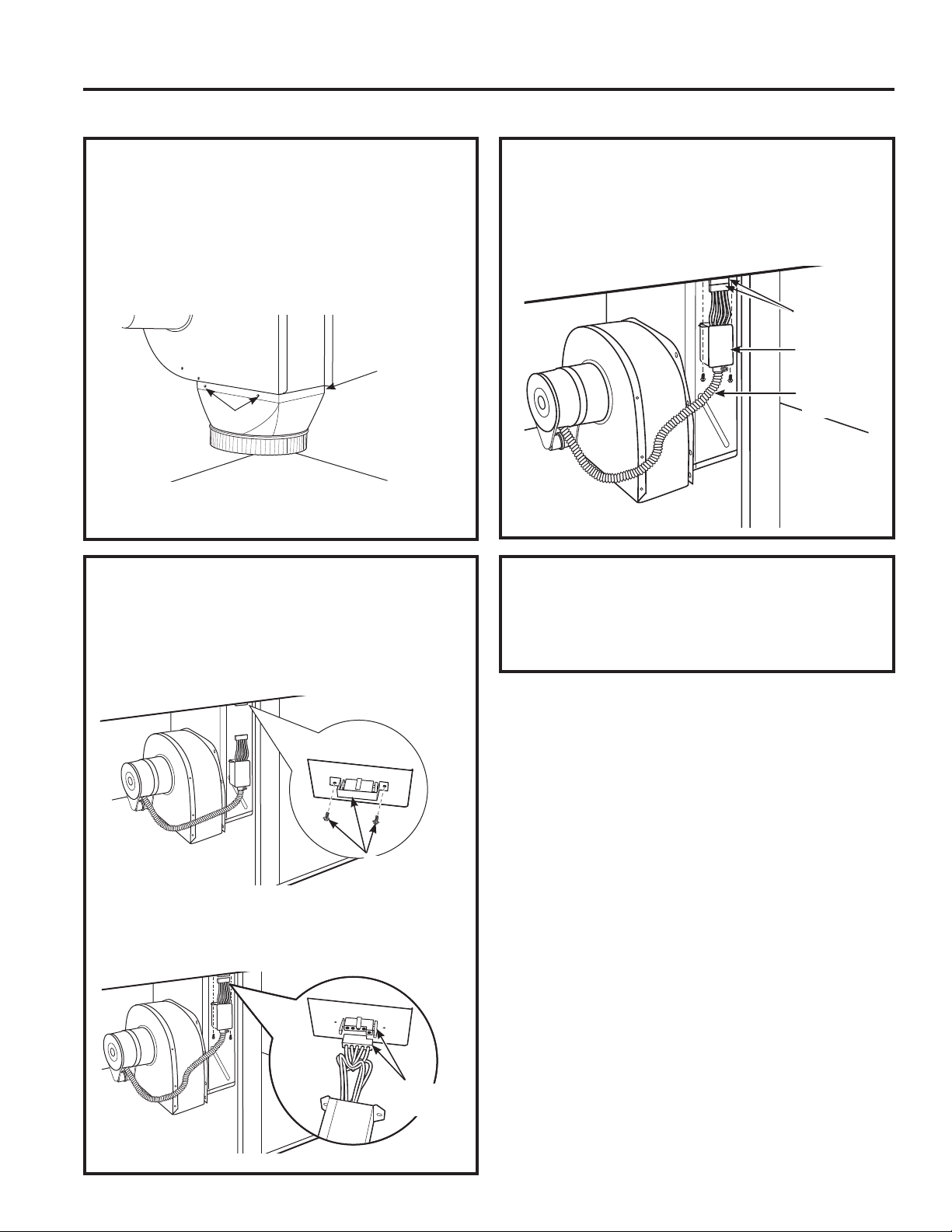
12. INSTALLING THE BLOWER TO
THE PLENUM
Orient the blower
discharge opening to
match the ductwork in
Steps 6 and 7. Slide the
four threaded studs on the
side of the blower housing
into the four holes on the
side of the plenum.
NOTE: See Step 13 for
installing the transition
duct to the blower. It
may be easier to install
the transition duct to the
blower before installing
the blower to the
plenum.
From the vent opening
in the top of the
cooktop, fasten the
blower assembly
securely to the plenum
with four (4) nuts.
Torque to 25±5 in/lb.
4 Nuts
(
7
/16”
socket
required)
Install 2 screws
Install 4 screws
22 49-2001160 Rev. 0
Installation Instructions
COOKTOP INSTALLATION (Cont.)
14. BLOWER ELECTRICAL
CONNECTIONS
• Loosen the two screws and remove and discard
the sheet metal strap covering the 5-pin connector
on the cooktop bottom. Save the screws for
reinstallation later.
• Connect the 5-pin plug on the blower assembly to
the matching 5-pin receptacle on the bottom of the
cooktop.
15. BLOWER ELECTRICAL
CONNECTIONS (CONT.)
• Fold all wires into the electrical enclosure. Secure
the enclosure with the screws removed earlier,
making sure that no wires are trapped.
16. CONNECTING THE
DUCTWORK
Connect the ductwork prepared in Steps 6 and 7
to the blower.
INSTALLATION INSTRUCTIONS
Remove screws
and discard
strap
5-pin
connectors
5-pin
connectors
Electrical
enclosure
Flexible
conduit
13. ATTACHING A BLOWER
TRANSITION DUCT
8VHDEORZHUWUDQVLWLRQGXFWIRUDOOGRZQZDUG
duct installations to connect to 6” round standard
GXFWZRUN7KLV»´[´UHFWDQJOHWR´URXQG
transition duct is available at your local building
supply store.
Install the transition duct to the blower outlet. Secure
all joints with duct tape to assure an airtight seal
Screws
Screw
(on other
side)
49-2001160 Rev. 0 23
INSTALLATION INSTRUCTIONS
Installation Instructions
COOKTOP INSTALLATION (Cont.)
17. BEFORE MAKING
ELECTRICAL CONNECTIONS
Note to Electrician: The power leads supplied with
WKLVDSSOLDQFHDUH8/UHFRJQL]HGIRUFRQQHFWLRQWR
large gauge household wiring.
The insulation of these leads is rated at
temperatures much higher than the temperature
rating of household wiring. The current carrying
capacity of a conductor is governed by the wire
gauge and also the temperature rating of the
insulation around the wire.
WARNING
Aluminum Wiring - IMPROPER
CONNECTION OF ALUMINUM HOUSE WIRING
TO THE COPPER LEADS CAN RESULT IN
SERIOUS PROBLEMS.
Attach copper wires to aluminum wiring using
VSHFLDOFRQQHFWRUVGHVLJQHGDQG8/OLVWHGIRU
joining copper to aluminum. Follow the connector
manufacturer’s recommended procedure closely.
Service Loop – Leave a loop in the wires to the
cooktop so that the cooktop can be lifted 12 inches
without having to disconnect the wiring.
ELECTRICAL REQUIREMENTS*
Model # Voltage Frequency KW
PP9830 120/240V 60Hz 9.1KW
208Y/120V 60Hz 6.9KW
* For reference only. Verify with product rating plate.
Rating Plate
18. MAKING ELECTRICAL
CONNECTIONS
WARNING
Switch power off at the service
panel and lock the service disconnecting means
to prevent power from being switched on
accidentally. When the service disconnecting
means cannot be locked, securely fasten a
prominent warning device, such as a tag, to the
service panel.
A. When making the wire connections, use the
entire length of conduit provided. The conduit
must not be shortened.
%:LWKWKHFRRNWRSLQSODFHRSHQWKHIURQWRIWKH
cabinet door.
C. Insert the wires from the conduit through the
opening of the junction box. Install proper strain
relief clamp.
Effective January 1, 1996, the National Electrical
Code requires that new, but not existing,
construction utilize a four-conductor connection to
an electric range. When installing an electric range
in new construction, follow the instructions in NEW
&216758&7,21$1')285&21'8&725
%5$1&+&,5&8,7&211(&7,21
You must use a three-wire, single-phase AC
208Y/120 Volt or 240/120 Volt, 60 Hertz electrical
system with separate ground. If you connect to
aluminum wiring, properly installed connectors
approved for use with aluminum wiring must be
used.
New construction and four-conductor branch
circuit connection
• When installing in new construction, or
• When installing in a mobile home, or
• When local codes do not permit grounding through
neutral:
24 49-2001160 Rev. 0
Installation Instructions
COOKTOP INSTALLATION (Cont.)
INSTALLATION INSTRUCTIONS
18. MAKING ELECTRICAL
CONNECTIONS (Cont.)
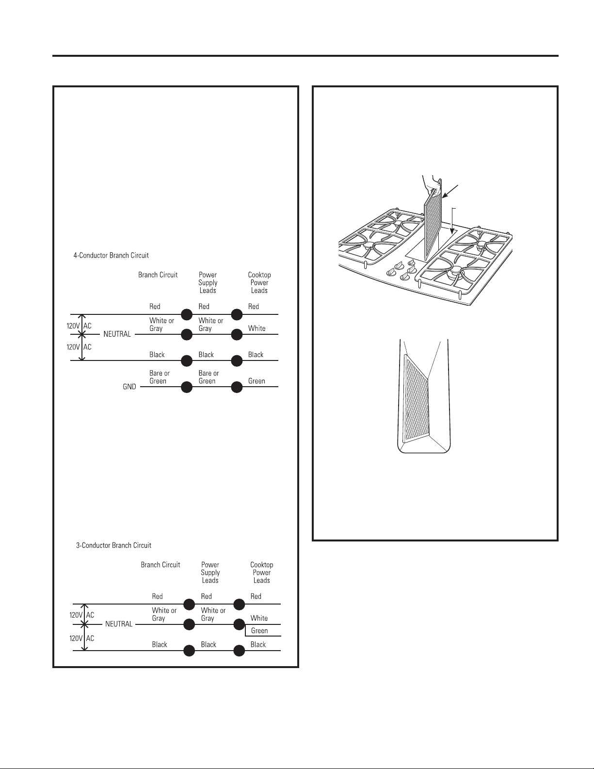
4-Conductor Branch Circuit
When connecting the cooktop to a 4-conductor
circuit, connect the red leads of the cooktop and the
power supply to the branch circuit red lead; connect
the black leads to each other. Connect the cooktop
white lead to the power supply and branch circuit
neutral leads, which are white or gray. Ground
the unit by connecting the green conductor of the
cooktop to the bare or green leads of the power
supply and branch circuit (ground leads).
Three-conductor branch circuit connection
• When installing in existing construction built prior
to January 1, 1996, and if permitted by local
codes:
3-Conductor Branch Circuit
When connecting cooktop to a 3-conductor circuit,
connect the red leads of the cooktop and the power
supply to the branch circuit red lead; connect the
black leads to each other. Connect the green and
white leads of the cooktop to the power supply and
branch circuit neutral leads, which are white or gray.
20. INSTALL DOWNDRAFT FILTER
AND VENT GRILLE
'RQRWRSHUDWHWKHYHQWZLWKRXWWKHILOWHULQSODFH
• Place the filter diagonally through the vent
opening.
• Make sure it rests, at an angle, on the supports in
the vent opening.
• Carefully place the vent grille onto the gasket on
the downdraft opening.
CHECK OPERATION OF DOWNDRAFT
7XUQWKHYHQWIDQVSHHGFRQWUROWR+,0('DQG
LO to make sure all speeds operate correctly.
Vent Filter
Vent
Chamber
49-2001160 Rev. 0 25
TROUBLESHOOTING TIPS
Troubleshooting Tips ... %HIRUH\RXFDOOIRUVHUYLFH
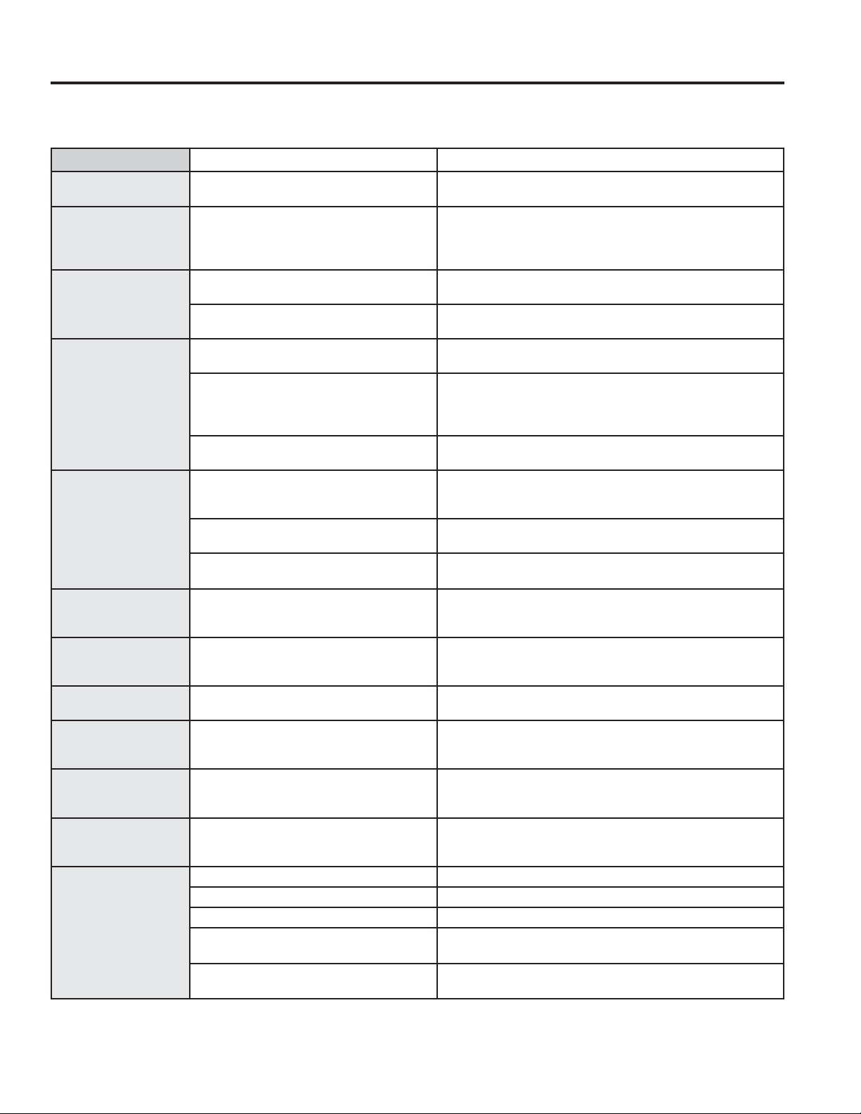
Problem Possible Cause What To Do
Water won’t boil Cover pan with a lid. Turn the downdraft fan Off until the
water begins to boil.
Surface units
will not maintain
a rolling boil or
cooking is slow
Improper cookware being used. Pan bottoms should be flat, fairly heavyweight and the
same diameter as the surface unit selected.
Surface units do
not work properly
A fuse in your home may be blown or
the circuit breaker tripped.
Replace the fuse or reset the circuit breaker.
Cooktop controls improperly set. Check to see the correct control is set for the surface unit
you are using.
Tiny scratches or
metal marks (may
appear as cracks)
or abrasions on
radiant cooktop
glass surface
Incorrect cleaning methods being
used.
See the Cleaning the Glass Cooktop section.
Cookware with rough bottoms being
used or coarse particles (salt or sand)
were between the cookware and the
surface of the cooktop.
%HVXUHFRRNZDUHERWWRPVDQGFRRNZDUHDUHFOHDQEHIRUH
XVH8VHFRRNZDUHZLWKVPRRWKERWWRPV7LQ\VFUDWFKHV
are not removable but will become less visible in time as a
result of cleaning.
Cookware has been slid across the
cooktop surface.
Pick up cookware to locate it on the glass surface.
Areas of
discoloration or
dark streaks on the
cooktop
Improper cookware being used. Marks from aluminum and copper pans as well as mineral
deposits from water or food can be removed with the
cleaning cream.
Food spillovers not cleaned before
next use.
See the Cleaning the Glass Cooktop section.
Incorrect cleaning methods being
used.
8VHUHFRPPHQGHGFOHDQLQJSURFHGXUHV
Hot sugar mixtures
or plastic melted to
the surface
Hot cooktop came into contact with
these substances.
See the Glass surface —potential for permaent damage
section in the Cleaning the Glass Cooktop section.
Pitting (or
indentation) of the
cooktop
Hot sugar mixture spilled or plastic
melted on the cooktop.
Call a qualified technician for replacement.
Cooktop making an
audible sound
Cooktop is locked. Check to be sure the Control Lock knob is turned to
81/2&.
Frequent cycling off
and on of surface
units
Improper cookware being used. 8VHRQO\IODWFRRNZDUHWRPLQLPL]HF\FOLQJ
Cooktop feels hot Improper cookware being used. The glass cooktop surface may seem hotter than you are
XVHGWR7KLVLVQRUPDO8VHSDQVZKLFKDUHDEVROXWHO\
flat.
Control knob will
not turn
Cooktop controls improperly set. When the knob is in the Off position, it must be pushed
down before it can be turned. When the knob is in any
other position, it can be turned without being pushed in.
Poor venting Clogged filter. Clean filter per instructions.
House too airtight. Open a window slightly to provide fresh air source.
Wall cap obstructed. Remove blockage from exterior wall cap.
Wall cap damper door stuck. Check exterior wall cap damper door for free movement or
obstruction.
Duct length exceeds recommended
100 equivalent foot maximum.
Reduce number of elbows to simplify duct run.
Save time and money! Review the charts on the following pages first and you may not need to call for service.
Check out self-help videos and FAQ at GEAppliances.com/support.
26 49-2001160 Rev. 0
GEAppliances.com
All warranty service is provided by our Factory Service Centers, or an authorized Customer Care
®
technician. To schedule
service online, visit us at GEAppliances.com/service, or call GE Appliances at 800.GE.CARES (800.432.2737). Please
have your serial number and your model number available when calling for service.
Servicing your appliance may require the use of the onboard data port for diagnostics. This gives a GE Appliances factory
service technician the ability to quickly diagnose any issues with your appliance and helps GE Appliances improve its
products by providing GE Appliances with information on your appliance. If you do not want your appliance data to be
sent to GE Appliances, please advise your technician not to submit the data to GE Appliances at the time of service.
What GE Appliances will not cover:
Ŷ Service trips to your home to teach you how to use
the product.
Ŷ ,PSURSHULQVWDOODWLRQGHOLYHU\RUPDLQWHQDQFH
Ŷ )DLOXUHRIWKHSURGXFWLILWLVDEXVHGPLVXVHG
modified or used for other than the intended purpose
or used commercially.
Ŷ 'DPDJHWRWKHJODVVFRRNWRSFDXVHGE\XVHRI
cleaners other than the recommended cleaning
creams and pads.
Ŷ 'DPDJHWRWKHJODVVFRRNWRSFDXVHGE\KDUGHQHG
spills of sugary materials or melted plastic that are
not cleaned according to the directions in the
Owner’s Manual.
Ŷ 5HSODFHPHQWRIKRXVHIXVHVRUUHVHWWLQJRIFLUFXLW
breakers.
Ŷ 'DPDJHWRWKHSURGXFWFDXVHGE\DFFLGHQWILUH
floods or acts of God.
Ŷ ,QFLGHQWDORUFRQVHTXHQWLDOGDPDJHFDXVHGE\
possible defects with this appliance.
Ŷ 'DPDJHFDXVHGDIWHUGHOLYHU\
Ŷ 3URGXFWQRWDFFHVVLEOHWRSURYLGHUHTXLUHGVHUYLFH
Ŷ 6HUYLFHWRUHSDLURUUHSODFHOLJKWEXOEVH[FHSWIRU
/('ODPSV
Ŷ (IIHFWLYH-DQXDU\FRVPHWLFGDPDJHWRWKH
glass cooktop such as, but not limited to, chips,
scratches, or baked on residue not reported within 90
days of installation.
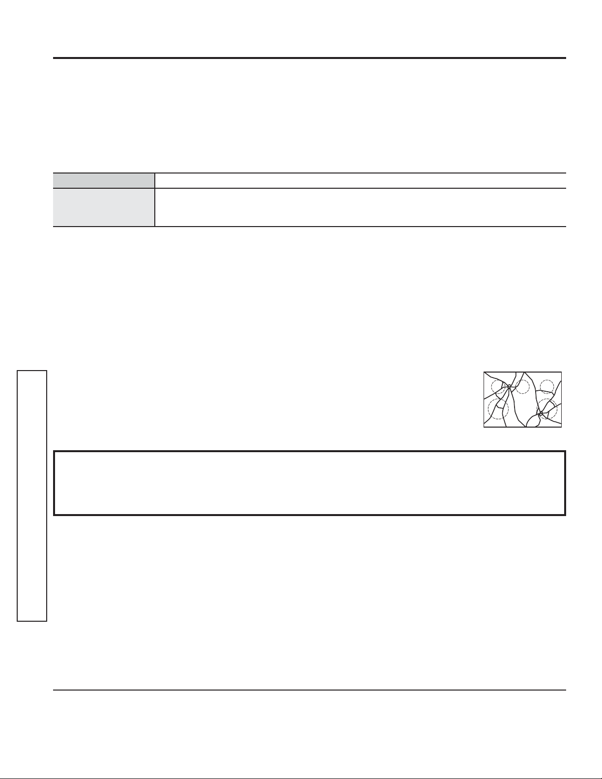
Ŷ (IIHFWLYH-DQXDU\
damage to the glass cooktop
due to impact or misuse. See
example.
EXCLUSION OF IMPLIED WARRANTIES
Your sole and exclusive remedy is product repair as provided in this Limited Warranty. Any implied warranties,
including the implied warranties of merchantability or fitness for a particular purpose, are limited to one year or
the shortest period allowed by law.
For the period of GE Appliances will replace
One year
From the date of the
original purchase
Any partRIWKHFRRNWRSZKLFKIDLOVGXHWRDGHIHFWLQPDWHULDOVRUZRUNPDQVKLS'XULQJ
this limited one-year warranty, GE Appliances will provide, free of charge, all labor and
in-home service to replace the defective part.
Staple your receipt here. Proof of the original purchase
date is needed to obtain service under the warranty.
LIMITED WARRANTY
Limited Warranty
This limited warranty is extended to the original purchaser and any succeeding owner for products purchased for
KRPHXVHZLWKLQWKH86$,IWKHSURGXFWLVORFDWHGLQDQDUHDZKHUHVHUYLFHE\D*($SSOLDQFHV$XWKRUL]HG6HUYLFHU
is not available, you may be responsible for a trip charge or you may be required to bring the product to an Authorized
GE Appliances Service location for service. In Alaska, the limited warranty excludes the cost of shipping or service
calls to your home.
Some states do not allow the exclusion or limitation of incidental or consequential damages. This limited warranty
gives you specific legal rights, and you may also have other rights which vary from state to state. To know what your
legal rights are, consult your local or state consumer affairs office or your state’s Attorney General.
Warrantor: GE Appliances, a Haier company
Louisville, KY 40225
Warrantor in Canada: MC Commercial
%XUOLQJWRQ21/5%
Extended Warranties: Purchase a GE Appliances extended warranty and learn about special discounts that are
available while your warranty is still in effect. You can purchase it online anytime at
GEAppliances.com/extended-warranty
or call 800.626.2224 during normal business hours. GE Appliances Service will still be there after your warranty expires.

49-2001160 Rev. 0 27
ACCESSORIES
Looking For Something More?
GE Appliances offers a variety of accessories to
improve your cooking and maintenance experiences!
Refer to the Consumer Support page for phone numbers
and website information.
The following products and more are available:
Accessories
Accessories
Alternate Installation Kit
Cleaning Supplies
CitruShine™ Stainless Steel Wipes
Stainless Steel Polishing Cloth
%XUQW2Q*UHDVH5HPRYHU
Stainless Steel Appliance Cleaner
Non-scratch Cleaning Pads for Ceramic Cooktops
Ceramic Glass Cooktop Cleaner
Cleaning Kit
Stainless Steel Scratch Remover Kit

28 49-2001160 Rev. 0
3ULQWHGLQWKH8QLWHG6WDWHV
Consumer Support
CONSUMER SUPPORT
GE Appliances Website
Have a question or need assistance with your appliance? Try the GE Appliances Website 24 hours a day, any day
of the year! You can also shop for more great GE Appliances products and take advantage of all our on-line support
VHUYLFHVGHVLJQHGIRU\RXUFRQYHQLHQFH,QWKH86GEAppliances.com
Register Your Appliance
Register your new appliance on-line at your convenience! Timely product registration will allow for enhanced
communication and prompt service under the terms of your warranty, should the need arise. You may also mail in
WKHSUHSULQWHGUHJLVWUDWLRQFDUGLQFOXGHGLQWKHSDFNLQJPDWHULDO,QWKH86GEAppliances.com/register
Schedule Service
Expert GE Appliances repair service is only one step away from your door. Get on-line and schedule your service at
\RXUFRQYHQLHQFHDQ\GD\RIWKH\HDU,QWKH86GEAppliances.com/service
or call 800.432.2737 during normal business hours.
Extended Warranties
Purchase a GE Appliances extended warranty and learn about special discounts that are available while your
warranty is still in effect. You can purchase it on-line anytime. GE Appliances Services will still be there after your
ZDUUDQW\H[SLUHV,QWKH86GEAppliances.com/extended-warranty
or call 800.626.2224 during normal business hours.
Remote Connectivity
For assistance with wireless network connectivity (for models with remote enable),
visit our website at GEAppliances.com/connect RUFDOOLQWKH86
Parts and Accessories
Individuals qualified to service their own appliances can have parts or accessories sent directly to their homes
9,6$0DVWHU&DUGDQG'LVFRYHUFDUGVDUHDFFHSWHG2UGHURQOLQHWRGD\KRXUVHYHU\GD\
,QWKH86GEApplianceparts.com or by phone at 877.959.8688 during normal business hours.
Instructions contained in this manual cover procedures to be performed by any user. Other servicing
generally should be referred to qualified service personnel. Caution must be exercised, since improper
servicing may cause unsafe operation.
Contact Us
If you are not satisfied with the service you receive from GE Appliances, contact us on our Website with all the
details including your phone number, or write to:
,QWKH86*HQHUDO0DQDJHU&XVWRPHU5HODWLRQV_*($SSOLDQFHV$SSOLDQFH3DUN_/RXLVYLOOH.<
GEAppliances.com/contact

Manual del propietario
e instalación
49-2001160 Rev. 0 09-22 GEA
PP9830
GE es una marca registrada de General Electric Company. Fabricado bajo licencia de marca.
ESPAÑOL
INFORMACIÓN DE SEGURIDAD ...3
USO DE LA PLACA DE COCCIÓN
Funciones de la Placa de Cocción ...........6
Quemadores .............................7
Utensilio para Placa de Cocción
para Vidrio Radiante ...................10
CUIDADO Y LIMPIEZA
Limpieza de la Placa de Cocción ........... 11
Cómo Limpiar la Estufa de Vidrio ..........12
INSTRUCCIONES
DE INSTALACIÓN ................14
Antes de Comenzar ......................14
Desempacando su Estufa .................17
Preparación de la Instalación ..............18
Cómo Instalar la Estufa ...................21
CONSEJOS PARA LA SOLUCIÓN
DE PROBLEMAS ..................26
GARANTÍA LIMITADA .............27
ACCESORIOS .......................29
SOPORTE PARA
EL CONSUMIDOR ................ 30
Escriba el modelo y los números de
serie a continuación:
Modelo No: _____________
Serie No: _______________
Encuentre estos números en una
etiqueta debajo de la estufa.
Estufa
radiante de ventilación descendente

2 49-2001160 Rev. 0
GRACIAS POR HACER QUE GE APPLIANCES SEA PARTE DE SU HOGAR.
Ya sea que haya crecido usando GE Appliances, o que ésta es su primera vez, nos complace
tenerlo en la familia.
Sentimos orgullo por el nivel de arte, innovación y diseño de cada uno de los electrodomésticos de
GE Appliances, y creemos que usted también. Entre otras cosas, el registro de su electrodoméstico
asegura que podamos entregarle información importante del producto y detalles de la garantía
cuando los necesite.
Registre su electrodoméstico GE ahora a través de Internet. Sitios Web y números telefónicos útiles
están disponibles en la sección de Soporte para el Consumidor de este Manual del Propietario.
También puede enviar una carta en la tarjeta de inscripción preimpresa que se incluye con
el material embalado.
49-2001160 Rev. 0 3
ADVERTENCIA
INSTRUCCIONES GENERALES DE SEGURIDAD
Ŷ 8VHHVWHDSDUDWRVyORFRQHOREMHWLYRSDUDHOTXHIXH
creado,como se describe en este Manual del Propietario
Ŷ 6ROLFLWHTXHXQLQVWDODGRUFDOLILFDGRLQVWDOHVXVXSHUILFLH
de cocción y que la conecte a tierra correctamente, de
acuerdo con las Instrucciones de Instalación.
Ŷ &XDOTXLHUDMXVWHUHSDUDFLyQRVHUYLFLRWpFQLFRQR
recomendado específicamente en este manual deberá
ser realizado SOLO por un instalador o técnico del
servicio calificado en superficies de cocción.
Ŷ $QWHVGHUHDOL]DUFXDOTXLHUFODVHGHUHSDUDFLyQ
desenchufe la cocina o desconecte el suministro eléctrico
desde el panel de distribución doméstico quitando el
fusible o desconectando el interruptor de circuitos.
Ŷ $VHJ~UHVHGHTXHWRGRVORVPDWHULDOHVGHHPEDODMHVHDQ
retirados de la superficie de cocción antes de su uso, a
fin de evitar que estos materiales se incendien.
Ŷ 1RGHMHDORVQLxRVVRORVRVLQDWHQFLyQVLODHVWXIDVH
encuentra caliente o funcionando. Podrían quemarse
gravemente.
Ŷ
PRECAUCIÓN
1RFRORTXHDUWtFXORVGHLQWHUpV
para los niños en los gabinetes que estén sobre una
estufa/ módulo superior de estufa – si los niños trepan
sobre la estufa para alcanzar estos artículos podrán sufrir
lesiones graves.
Ŷ 1RGHMHDORVQLxRVVRORVRVLQDWHQFLyQVLODHVWXIDVH
encuentra caliente o funcionando. Podrían quemarse
gravemente.
Ŷ 8VHVyORDJDUUDGHUDVGHROODVVHFDV±ODVDJDUUDGHUDV
húmedas sobre superficies calientes podrán producir
TXHPDGXUDVGHELGRDOYDSRU1RSHUPLWDTXHODV
agarraderas tengan contacto con los elementos de
unidades calientes de la superficie ni con los elementos
SDUDFDOHQWDU1RXVHXQDWRDOODXRWUDWHODYROXPLQRVD
para reemplazar la agarradera.
Ŷ 1XQFDXVHVXHOHFWURGRPpVWLFRSDUDFDOHQWDUOD
habitación.
Ŷ 1RWRTXHODVXQLGDGHVGHVXSHUILFLHORVHOHPHQWRV
calentadores o la superficie interior del horno. Estas
superficies pueden estar lo suficientemente calientes para
quemar aún cuando tengan un color oscuro. Durante
y después del uso, no toque o deje que su vestimenta
u otros materiales inflamables entren en contacto con
unidades de superficie, áreas cercanas a las unidades
de superficie o cualquier área interior del horno; deje
pasar un tiempo prudencial para que se enfríen. Otras
superficies del aparato pueden calentarse lo suficiente
como para provocar quemaduras. Las superficies
potencialmente calientes incluyen la estufa, las áreas
orientadas hacia la estufa, la abertura de ventilación
del horno, las superficies cercan asa la abertura y las
hendiduras ubicadas alrededor de la puerta del horno.
Ŷ 1RFDOLHQWHUHFLSLHQWHVFHUUDGRVGHDOLPHQWRV3RGUtD
haber una acumulación de presión en el recipiente y éste
podría explotar, provocando lesiones.
ADVERTENCIA
MANTENGA LOS MATERIALES INFLAMABLES ALEJADOS
DE LA ESTUFA.
Ŷ
ADVERTENCIA
5,(6*2'(,1&(1',2
1XQFDGHMHODHVWXIDGHVDWHQGLGDFXDQGRODVXSHUILFLH
GHFRFFLyQVHHQFXHQWUH(1&(1','$0DQWHQJD
cualquier artículo inflamable alejado de la estufa. Apague
todos los controles cuando finalice la cocción. Si no se
siguen estas instrucciones se podrán producir incendios,
lesiones graves o la muerte.
Ŷ 6LHPSUHPDQWHQJDODVSDUHGHVFRPEXVWLEOHVTXHVH
puedan incendiar), cortinas o cubiertas a una distancia
segura de la estufa.
Ŷ 1RFRORTXHQLJXDUGHtWHPVTXHVHSXHGDQGHUUHWLUR
incendiar sobre la superficie de cocción de vidrio, incluso
cuando ésta no se encuentre en uso. Mantenga el área
del electrodoméstico despejada y libre de materiales
combustibles, gasolina y otros vapores y líquidos
inflamables. Si la superficie de cocción se enciende de
forma accidental, dichos productos se podrán incendiar.
El calor de la superficie de cocción o de la ventilación del
horno luego de que éste fue apagado podrán hacer que
dichos productos se incendien también.
Ŷ 1RFRORTXHREMHWRVPHWiOLFRVWDOHVFRPRFXFKLOORV
tenedores, cucharas y tapas sobre la base de la
superficie de cocción, ya que estos se podrán calentar.
Ŷ 1XQFDXVHYHVWLPHQWDVKROJDGDVRDPSOLDVPLHQWUDV
utilice el aparato. Estas vestimentas pueden prenderse
fuego si entran en contacto con superficies calientes,
provocando quemaduras graves.
Ŷ 1RSHUPLWDTXHODJUDVDGHODFRFFLyQXRWURVPDWHULDOHV
inflamables se acumulen dentro de la cocina o en su
cercanía. La grasa dentro del horno o sobre la estufa
puede encenderse.
Ŷ /LPSLHODVFDPSDQDVGHYHQWLODFLyQFRQIUHFXHQFLD1R
debe permitirse la acumulación de grasa en la campana
o en el filtro.
LEA Y GUARDE ESTAS INSTRUCCIONES
INFORMACIÓN IMPORTANTE DE SEGURIDAD
LEA TODAS LAS INSTRUCCIONES ANTES DE USAR ESTE ELECTRODOMÉSTICO
INFORMACIÓN DE SEGURIDAD
ADVERTENCIA
/HDWRGDVODVLQVWUXFFLRQHVGHVHJXULGDGDQWHVGHXWLOL]DUHVWHSURGXFWR1RVHJXLUHVWDVLQVWUXFFLRQHV
puede generar un incendio, una descarga eléctrica, lesiones corporales o la muerte.

4 49-2001160 Rev. 0
ADVERTENCIA
INSTRUCCIONES DE SEGURIDAD DE LA ESTUFA RADIANTE
Ŷ
ADVERTENCIA
181&$GHVDWLHQGDOD
sección de cocción de la superficie superior de este
electrodoméstico mientras esté en uso. Los hervores
excesivos causan vapores y derrames de grasa que
VHSXHGHQLQFHQGLDU1RVHJXLUODDILUPDFLyQGHHVWD
advertencia podrá resultar en incendio, explosión, o
riesgos de quemaduras que podrán ocasionar daños
sobre la propiedad, lesiones personales o la muerte.
Ŷ /DVFRPLGDVHVSHFLDOPHQWHODVFRPLGDVFRQDFHLWHVH
pueden incendiar, lo cual podrá ocasionar un incendio
que se propague a los gabinetes próximos. Si se produce
un incendio, manténgase alejado del electrodoméstico y
de inmediato llame al departamento de bomberos.
Ŷ 1XQFDSLHUGDGHYLVWDHODFHLWHFXDQGRHVWpIULHQGR6L
se calienta más allá de su punto de cocción, el aceite
se podrá incendiar y provocar un incendio que se puede
SURSDJDUDORVJDELQHWHVSUy[LPRV12,17(17(
(;7,1*8,5&21$*8$81,1&(1',2352'8&,'2
&21&20%867,%/(*5$6$
Ŷ 1RXVHDJXDVREUHHOIXHJRGHODJUDVD1XQFDWRPH
una olla que se esté incendiando. Apague los controles.
Extinga la olla que se esté incendiando sobre una unidad
de la superficie cubriendo la misma completamente con
su tapa correspondiente, una charola metálica de galletas
o una charola plana, o use un químico seco multiuso o un
extinguidor de incendios de espuma a chorro.
Ŷ 8VHXQWHUPyPHWURSDUDJUDVDVSURIXQGDVVLHPSUHTXH
sea posible para monitorear la temperatura del aceite.
A fin de evitar derrames e incendios con aceite, use
una cantidad mínima de aceite cuando esté friendo en
una olla que no sea profunda y evite cocinar comidas
congeladas con cantidades excesivas de hielo.
Ŷ 8WLOLFHHOWDPDxRGHUHFLSLHQWHDGHFXDGR(OLMDUHFLSLHQWHV
con bases planas lo suficientemente grandes para cubrir
el elemento calentador de superficie. La utilización de
recipientes más pequeños dejará expuesta una porción
de la unidad de superficie al contacto directo, lo que
SXHGHSURYRFDUHOHQFHQGLGRGHVXVYHVWLPHQWDV8QD
relación adecuada del recipiente con la unidad de
superficie también mejorará la eficiencia.
Ŷ $OXVDUXWHQVLOLRVGHYLGULRFHUiPLFDDVHJ~UHVHGH
que sean adecuados para el servicio de la superficie de
cocción; otros se podrán romper debido a un cambio
repentino de temperatura.
Ŷ 3DUDPLQLPL]DUODSRVLELOLGDGGHTXHPDGXUDVHO
encendido de materiales inflamables y los derrames, la
manija de los recipientes deben girarse hacia el centro
de la cocina sin extenderse sobre ninguna unidad de
superficie cercana.
Ŷ 6LIODPEHDDOLPHQWRVEDMRODFDPSDQDHQFLHQGDHO
ventilador.
Ŷ 7HQJDFXLGDGRDOWRFDUODHVWXID/DVXSHUILFLHGHYLGULR
de la estufa retendrá calor después de que los controles
se hayan apagado.
Ŷ 6LVHSURGXFHXQFRUWHGHFRUULHQWHHQXQDVXSHUILFLH
de cocción eléctrica mientras la unidad de la superficie
HVWiHQ21(QFHQGLGRpVWD~OWLPDVHYROYHUiD
encender cuando regrese la corriente. En caso de falta
de corriente, si no se giran todas las perillas de la unidad
GHODVXSHUILFLHDODSRVLFLyQ2))$SDJDGRVHSRGUiQ
incendiar artículos en o cerca de la cocina, lo cual podrá
producir lesiones graves o la muerte.
Ŷ (YLWHUD\DURJROSHDUODHVWXIDGHYLGULR(VWRSRGUtD
romper el vidrio. La estufa puede sufrir rayones con
artículos tales como cuchillos, instrumentos punte
agudos, anillos u otras joyas y abrojos de vestimentas.
Ŷ $QWHVGHXWLOL]DUHOFLFORGHDXWROLPSLH]DOLPSLHODJUDVD
\ORVGHUUDPHVGHDOLPHQWRVGHOKRUQR8QDFDQWLGDG
excesiva de grasa puede encenderse, generando daños
por el humo en su hogar.
Ŷ 1RFRORTXHRDOPDFHQHHOHPHQWRVTXHSXHGHQGHUUHWLUVH
o prenderse fuego sobre la estufa de vidrio, aún cuando
no la esté usando. Si la estufa se enciende en forma
accidental, pueden prenderse fuego. El calor proveniente
de la estufa o de la ventilación del horno también puede
prenderlos fuego, aún si el aparato está apagado.
Ŷ 8VHXQOLPSLDGRUSDUDVXSHUILFLHVGHFRFFLyQGH
cerámica y una almohadilla de limpieza antirayaduras
para limpiar la superficie de cocción. Espere hasta que
la superficie de cocción se enfríe y que la luz indicadora
VHDSDJXHDQWHVGHUHDOL]DUODOLPSLH]D8QDHVSRQMD
o tela húmedas sobre una superficie caliente podrán
ocasionar quemaduras con vapor. Algunos productos
de limpieza podrán producir gases nocivos si se aplican
sobre una superficie caliente. NOTA: Los derrames de
productos azucarados son una excepción. Se deberán
raspar mientras aún estén calientes, utilizando un guante
para horno y una espátula. Para acceder a instrucciones
detalladas, lea la sección de Limpieza de la Superficie de
Cocción de Vidrio.
Ŷ /HD\FXPSODFRQWRGDVODVLQVWUXFFLRQHV\DGYHUWHQFLDV
de la etiqueta de la crema de limpieza.
Ŷ 1XQFDXVHXQDHVWXIDGHVXSHUILFLHFRPRXQDVXSHUILFLH
de corte.
LEA Y GUARDE ESTAS INSTRUCCIONES
INFORMACIÓN DE SEGURIDAD
INFORMACIÓN IMPORTANTE DE SEGURIDAD
LEA TODAS LAS INSTRUCCIONES ANTES DE USAR ESTE ELECTRODOMÉSTICO

49-2001160 Rev. 0 5
INFORMACIÓN DE SEGURIDAD
LEA Y GUARDE ESTAS INSTRUCCIONES
INFORMACIÓN IMPORTANTE DE SEGURIDAD
LEA TODAS LAS INSTRUCCIONES ANTES DE USAR ESTE ELECTRODOMÉSTICO
Cómo Retirar la Película Protectora de Envío y la Cinta de Embalaje
Con cuidado tome un extremo de la película protectora
de envío con los dedos y lentamente retire la misma de la
VXSHUILFLHGHOHOHFWURGRPpVWLFR1RXWLOLFHQLQJ~QSURGXFWR
filoso para retirar la película. Retire toda la película antes de
usar el electrodoméstico por primera vez.
Para asegurar que no haya daños sobre el acabado del
producto, la forma más segura de retirar el adhesivo de la cinta
de embalaje en electrodomésticos nuevos es aplicando un
detergente líquido hogareño para lavar platos. Aplique con una
tela suave y deje que se seque.
NOTA: El adhesivo deberá ser eliminado de todas las partes.
1RVHSXHGHUHWLUDUVLVHKRUQHDFRQpVWHGHQWUR
Tenga en cuenta las opciones de reciclaje del material de
embalaje de su electrodoméstico.
FORMA ADECUADA DE DESCARTAR SU ELECTRODOMÉSTICO
Descarte o recicle su electrodoméstico de acuerdo con las Regulaciones Federales y Locales. Comuníquese con las
autoridades locales para descartar o reciclar su electrodoméstico de forma ambientalmente segura.
ADVERTENCIA
COCINE BIEN LAS CARNES Y LAS CARNES DE AVE
Cocine la comida completamente para evitar que se produzcan enfermedades a partir de la comida. Podrá
encontrar recomendaciones sobre temperatura mínima segura de la comida en IsItDoneYet.gov y
en fsis.usda.gov. 8VHXQWHUPyPHWURSDUDODFRPLGDSDUDFDOFXODUVXWHPSHUDWXUD\UHDOL]DUFRQWUROHVHQ
diferentes áreas.

6 49-2001160 Rev. 0
USO DE LA PLACA DE COCCIÓN: Funciones de la Placa de Cocción
Funciones de la Placa de Cocción
1. Unidad de superficie posterior izquierda
2. Unidad de superficie de puente
3. Unidad de superficie frontal izquierda
4. Parrilla de ventilación
5. Filtro de ventilación (debajo de la parrilla de
ventilación)
6. Unidad de superficie posterior derecha
7. Unidad de superficie doble
8. Etiqueta con los números de modelo y serie (debajo
de la estufa)
9. Control de la unidad de superficie posterior izquierda
10. Control de la unidad de superficie frontal izquierda
11. Luces indicadoras de que la superficie está
caliente del lado izquierdo (una por cada unidad de
superficie)
12. Control de velocidad del ventilador de ventilación
13. Perilla de bloqueo de control
14. Luces indicadoras de que la superficie está caliente
del lado derecho (una por cada unidad de superficie)
15. Control de unidad de superficie doble
16. Control de unidad de superficie posterior derecha
17. Luz indicadora encendida de la unidad de superficie
Es posible que las funciones y apariencias varíen con relación a su modelo a lo largo del manual.
Índice de características ODVFDUDFWHUtVWLFDV\ODDSDULHQFLDSRGUtDQYDULDU
4516
378
2
9
13
17
12
11
10 15
16
14
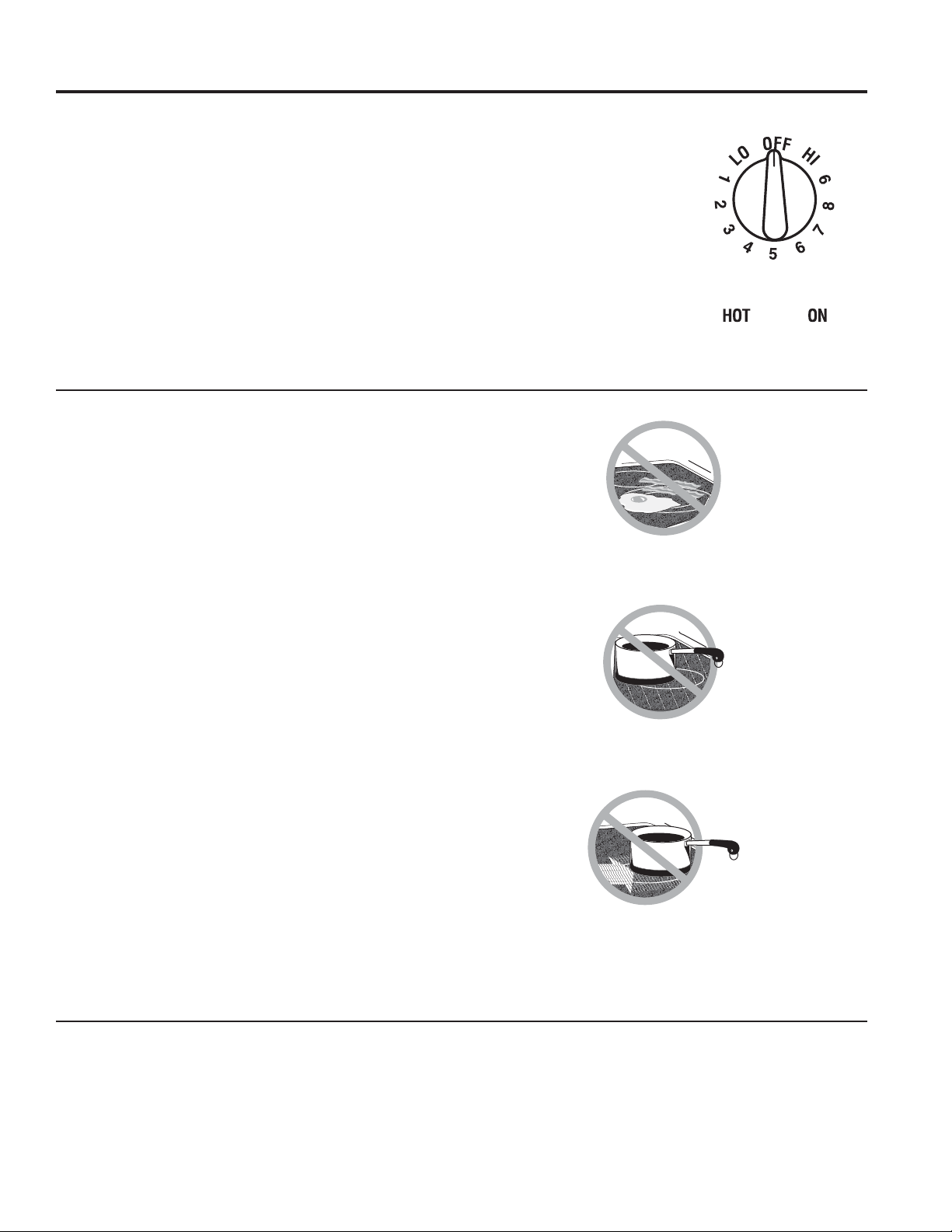
49-2001160 Rev. 0 7
Quemadores
USO DE LA PLACA DE COCCIÓN: Quemadores
Unidades de superficie radiantes
El control de la unidad de superficie radiante puede colocarse
HQFXDOTXLHUOXJDUHQWUH/2%DMR\+,$OWRSDUDXQQ~PHUR
de selecciones de calentamiento ilimitado. Con el interruptor
infinito el embobinado hace ciclo entre encendido y apagado
para mantener control de su selección.
Para hervir líquidos, use una olla o sartén que tenga tapa.
El botón de control debe empujarse hacia abajo y movido
GHVGHODSRVLFLyQ2))$SDJDGR&XDQGRORVERWRQHVGH
control están en cualquier posición que no sea apagado,
pueden moverse sin presionarlos.
Cerciórese de girar el botón de control a la posición apagado
FXDQGRWHUPLQHGHFRFLQDU8VWHGVHQWLUiXQFOLFHQODSRVLFLyQ
2))$SDJDGR
La luz indicadora de la unidad
de superficie brillará cuando
cualquiera de las unidades de
VXSHUILFLHHVWpQHQFHQGLGDV21
(QFHQGLGR
(OOX]LQGLFDGRUDGH+276XUIDFH
6XSHUILFLH&DOLHQWHEULOODUiQ
cuando la superficie de vidrio
esté caliente y permanecerá
así hasta que la misma se haya
enfriado.
Consejos para Productos Enlatados en el Hogar
Asegúrese que el producto enlatado se encuentre sobre la
unidad superficial.
Asegúrese de que el producto enlatado sea plano en su parte
inferior.
Para evitar quemadoras de vapor o calor, tenga cuidado al
enlatar el producto.
8VHUHFHWDV\SURFHGLPLHQWRVGHIXHQWHVFRQILDEOHV(VWRVVH
HQFXHQWUDQGLVSRQLEOHVDWUDYpVGHIDEULFDQWHVFRPR%DOO
®
y
Kerr
®
\HO'HSDUWPHQWRI$JULFXOWXUH([WHQVLRQ6HUYLFH6HUYLFLR
del Departamento de Agricultura).
El uso de enlatados cerrados a baño maría con fondos
ondeados podrán extender el tiempo requerido para traer el
agua al punto de hervor.
Acerca de las unidades de superficie radiantes
La estufa radiante tiene unidades calentadoras por debajo de
una superficie suave de vidrio.
127$8QRORUOLJHURHVQRUPDOFXDQGRXQDHVWXIDQXHYDHV
usada por primera vez. Esto es causado por el calentamiento
de las partes nuevas y los materiales de aislamiento y
desaparecerá en corto tiempo.
La superficie de cocción cuenta con unidades de Respuesta
Rápida en la superficie. La superficie de cocción se calentará
o enfriará de forma automática en la configuración del nivel de
potencia deseado y en el tiempo más rápido posible. Mientras
las unidades de la superficie se encuentren encendidas, es
posible que no las vea iluminadas de rojo durante ciertas
condiciones al calentar o enfriar.
Las temperaturas de la superficie de cocción se incrementan
con el número de unidades de la superficie que se encuentran
encendidas. Con 3 o 4 unidades encendidas, las temperaturas
de las superficie son altas. Siempre tenga cuidado al tocar la
superficie de cocción.
Aún después de que las unidades de superficie son apagadas,
la estufa de vidrio retiene suficiente calor para continuar
cocinando. Para evitar cocinar excesivamente, remueva las
sartenes de las unidades de superficie cuando la comida se
haya cocinado. Evite colocar ningún objeto sobre la superficie
hasta que se haya enfriado completamente.
Ŷ /DVPDQFKDVGHDJXDGHSyVLWRVGHPLQHUDOHVVH
remueven usando una crema de limpieza o vinagre blanco
puro.
Ŷ (OXVRGHOLPSLDGRUGHYHQWDQDVSRGUtDGHMDUXQDSHOtFXOD
iridiscente sobre la estufa. La crema de limpieza removerá
esta decoloración.
Ŷ 1RDOPDFHQHDUWtFXORVSHVDGRVVREUHODHVWXID6LVHFDHQ
sobre la estufa, podrían dañarla.
Ŷ 1RXVHODVXSHUILFLHFRPRWDEODGHFRUWH
Cerciórese de girar el botón de
FRQWURODDSDJDGR2))FXDQGR
termine de cocinar.
1XQFDFRFLQHGLUHFWDPHQWHVREUH
el vidrio. Siempre use piezas de
cocina.
Siempre coloque la sartén en el centro
de la unidad de superficie en la que está
cocinando.
1RGHVOLFHVDUWHQHVHQFLPDGHOD
superficie de la estufa porque esto podría
rasguñar el vidrio. El vidrio es resistente,
pero no es a prueba de rasguños.
COCINE SOBRE
LA SUPERFICIE
NO EN
CENTRO
DESLICE
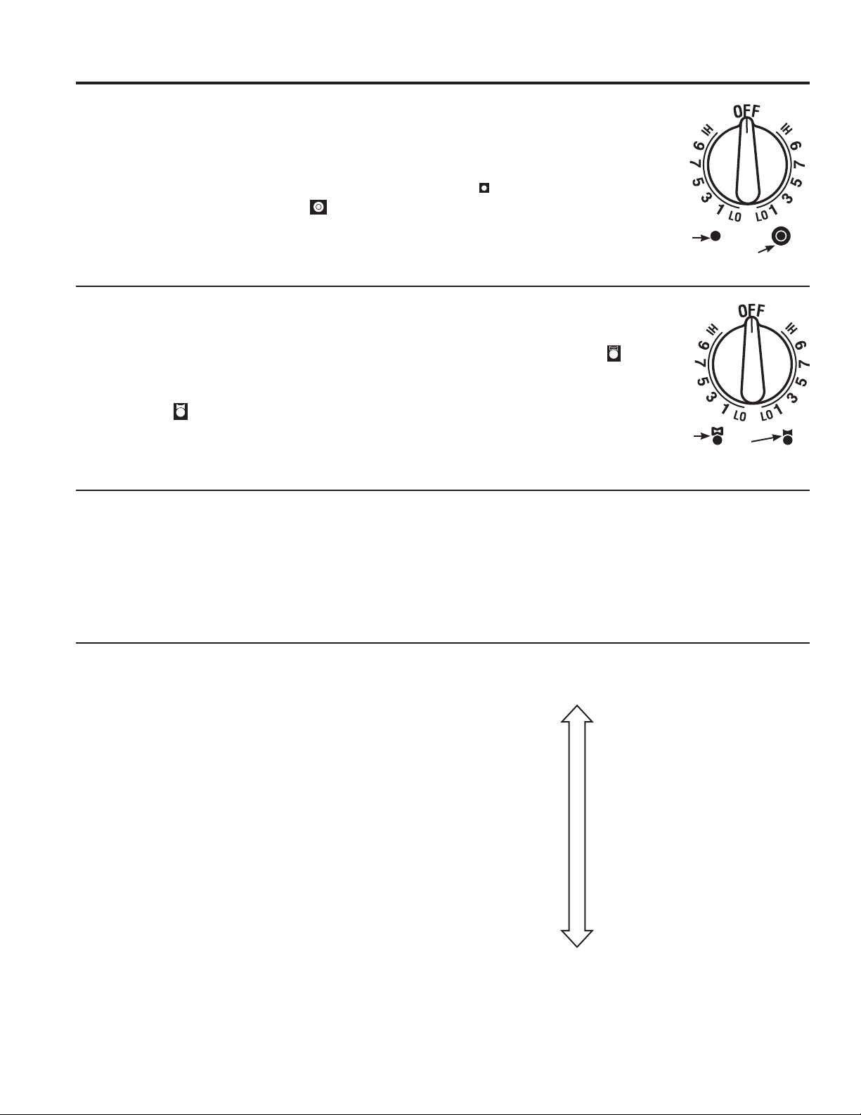
8 49-2001160 Rev. 0
Unidad de superficie de puente
Cerciórese de que la sartén descansa de manera plana
sobre la estufa de vidrio y de que no está descansando en
los extremos. Si usted nota poco rendimiento de cocción,
mueva la sartén para cerciorarse de que está apoyada de
manera plana sobre la estufa.
Para usar el quemador de puente, gire el botón del
quemador hacia
y seleccione el ajuste deseado. La
unidad calentará la superficie frontal y el puente.
Escoja sartenes que hagan juego con el área circular/puente
tanto como sea posible.
Para usar solamente la unidad
de superficie frontal, gire el
botón del quemador hacia
y
seleccione el ajuste deseado. La
unidad calentará el quemador de
superficie frontal.
8VWHGSXHGHFUHDUXQiUHDGH
calentamiento oblonga usando
la combinación de la unidad
posterior izquierda y el puente
de la unidad frontal.
Quemadores (Cont.)
USO DE LA PLACA DE COCCIÓN: Quemadores
Unidad de superficie doble
La unidad de superficie frontal derecha tiene dos tamaños
para cocinar entre los que usted puede escoger y así podrá
combinar el tamaño correcto de la sartén que se encuentre
usando con la unidad de superficie apropiada.
3DUDXVDUXQDXQLGDGGHVXSHUILFLHJUDQGH´JLUHHOERWyQ
en dirección de las agujas del reloj hacia
y seleccione
el ajuste deseado. La unidad calentará el área completa
contenida en el círculo grande.
Para usar la unidad de
VXSHUILFLHSHTXHxD´
gire el botón en dirección
contraria a las agujas del
reloj
y seleccione el
ajuste deseado. La unidad
calentará solamente el
área contenida en el círculo
pequeño.nside the smaller
circle.
Los elementos de superficie se encienden y apagan
Los elementos de superficie se encienden y apagan para
mantener la temperatura que usted ha seleccionado.
Todos los elementos de superficie cuentan con un limitador
de temperatura que protege la estufa de vidrio de calentarse
demasiado.
El limitador de temperatura puede apagar los elementos
GXUDQWHODFRFFLyQVL
Ŷ (OUHFLSLHQWHKLHUYHHQVHFR
Ŷ /DEDVHGHOUHFLSLHQWHQRHVSODQD
Ŷ (OUHFLSLHQWHQRHVWiFHQWUDGR
Ŷ 1RKD\XQUHFLSLHQWHHQHOHOHPHQWR
Selección de las Configuraciones de la Placa de Cocción
Seleccione el elemento/quemador que mejor se ajuste
al tamaño del utensilio. Cada elemento/quemador de su
nueva superficie de cocción cuenta con sus propios niveles
de potencia, desde la graduación baja hasta la alta. Las
configuraciones del nivel de potencia necesarias para
cocinar variarán dependiendo del utensilio que se use, el tipo
y cantidad de comida, y el resultado deseado.
(QJHQHUDO
Ŷ 88VHODVFRQILJXUDFLRQHVPiVEDMDVSDUDGHUUHWLU
mantener y hervir a fuego lento.
Ŷ 8VHODVFRQILJXUDFLRQHVPiVDOWDVSDUDFDOHQGDU
rápidamente, soasar, y freír.
Para mantener las comidas calientes, confirme que la
configuración seleccionada sea suficiente para mantener la
WHPSHUDWXUDGHODFRPLGDSRUHQFLPDGHORV)1RVH
recomienda el uso de elementos más grandes para derretir.
Los elementos para hervir con corriente se adaptan mejor
para hervir agua, particularmente con ollas de 9° o más.
Selección
de la unidad
de superficie
SHTXHxDGH´
Selección de la
unidad de superficie
JUDQGHGH´
Quemador
frontal y
puente
Quemador
frontal
solamente
Hi
boiling quickly
frying
searing
reducing
simmering
holding
melting
Low

49-2001160 Rev. 0 9
Bloqueo de control de las unidades de superficie
Para activar el bloqueo de control, gire la perilla Control Lock
%ORTXHRGHFRQWURODLOCK%ORTXHR(VWRQRSHUPLWLUiTXH
ODVXQLGDGHVGHVXSHUILFLHVHFDOLHQWHQ8QDOX]LQGLFDGRUD
se encenderá para demostrar que están bloqueadas. El
ventilador de corriente descendente permanecerá operable
con el bloqueo de control activado.
En la posición bloqueada, la estufa producirá un sonido
audible si cualquier perilla de control de unidad de superficie
se activa o gira a otra posición que no sea OFF$SDJDGR
USO DE LA PLACA DE COCCIÓN: Quemadores
Quemadores (Cont.)
Indicador Luminoso de Calor
8QDOX]LQGLFDGRUDGHVXSHUILFLHFDOLHQWHXQDSDUDFDGD
elemento de cocción) brillará cuando la superficie de
vidrio esté caliente, y permanecerá encendida hasta
que la superficie haya bajado su temperatura hasta una
temperatura que sea segura al tacto.
Cómo operar el sistema de ventilación
El sistema de ventilación incorporado ayuda a remover los
vapores de la cocina, los olores y el humo de las comidas
preparadas en la estufa.
Para operar el sistema de ventilación de aire descendente
GRZQGUDIWJLUHHOERWyQGHFRQWUROGHODYHORFLGDGGHO
YHQWLODGRUGHYHQWLODFLyQD+,$OWR0('0HGLRR/2
%DMRVHJ~QVHDQHFHVDULR
El uso continuo del sistema de ventilación mientras cocina
ayuda a mantener la cocina cómoda y menos húmeda,
reduciendo los olores de cocina y la humedad que
normalmente crea la necesidad frecuente de limpieza.
Luz Indicadora
de Superficie
Caliente

10 49-2001160 Rev. 0
Utensilio para Placa de Cocción para Vidrio Radiante
NOTA: Siga todas las recomendaciones del fabricante de recipientes cuando utilice cualquier clase
|de recipiente de cocción sobre la estufa cerámica.
La siguiente información lo ayudará a elegir los recipientes de cocción que brindan un buen
desempeño en estufas de vidrio.
Acero inoxidable:
Recomendado
Aluminio:
Se recomienda de capa gruesa
%XHQDFRQGXFWLYLGDG/RVUHVLGXRVGHDOXPLQLRDYHFHV
parecen rayones sobre la estufa pero pueden quitarse si se los
limpia de inmediato. Debido a su bajo punto de fusión, no debe
utilizarse aluminio de capa fina.
Base de cobre:
Recomendado
El cobre puede dejar residuos que pueden parecer rayones.
Los residuos pueden eliminarse, siempre y cuando la estufa se
limpie de inmediato. Sin embargo, no permita que estas ollas
hiervan en seco. El metal sobre calentado puede adherirse a
las estufas de vidrio. Si no se elimina de inmediato, una olla
con la base de cobre sobre calentado dejará un residuo que
manchará la estufa en forma permanente.
Esmalte de porcelana sobre hierro fundido:
Se recomienda si la base de la olla se encuentra revestida
Esmalte de porcelana
sobre acero:
1RVHUHFRPLHQGD
Calentar recipientes vacíos puede
provocar daños permanentes al
vidrio de las estufas. El esmalte
puede derretirse y adherirse a la
estufa cerámica.
Vidrio-cerámico:
1RVHUHFRPLHQGD
Desempeño pobre. Raya la
superficie.
Cerámica:
1RVHUHFRPLHQGD
Desempeño pobre. Puede rayar la
superficie.
Hierro fundido:
1RVHUHFRPLHQGDDPHQRVTXH
se encuentre específicamente
diseñado para estufas de vidrio
Pobre conductividad y lentitud para
absorber el calor. Raya la superficie
de la estufa.
Verifique que los recipientes
tengan bases planas
utilizando una regla.
1RVHUHFRPLHQGDQ
recipientes con bases
redondeadas, curvadas, con
rebordes o torceduras..
USO DE LA PLACA DE COCCIÓN: 8WHQVLOLRSDUD3ODFDGH&RFFLyQSDUD9LGULR5DGLDQWH
Para Mejores Resultados
Ŷ &RORTXHVyORUHFLSLHQWHVVHFRVVREUHORVHOHPHQWRVGH
VXSHUILFLH1RFRORTXHWDSDVVREUHORVHOHPHQWRVGH
superficie, en especial tapas mojadas.
Ŷ 1RXVHZRNVFRQDQLOORVGHVRSRUWH(VWDFODVHGHZRNQR
se calienta sobre elementos de superficie de vidrio.
Ŷ 5HFRPHQGDPRVHOXVRGHZRNVGHEDVHSODQDVRODPHQWH
Se encuentran disponibles en su negocio minorista local. La
EDVHGHOZRNGHEHWHQHUHOPLVPRGLiPHWURTXHHOHOHPHQWR
de superficie para asegurar un contacto adecuado.
Ŷ $OJXQRVSURFHGLPLHQWRVGHFRFFLyQHVSHFLDOHVUHTXLHUHQ
recipientes de cocción específicos, como ollas a presión,
freidoras, etc. Todos los recipientes de cocción deben tener
bases planas y ser del tamaño correcto.
Ŷ 1RSHUPLWDTXHORVDOLPHQWRVKLHUYDQHQVHFR\DTXHORV
recipientes decocción pueden adherirse a la superficie de
cocción, provocando daños permanentes a la estufa.
1RFRORTXHUHFLSLHQWHVPRMDGRV
sobre la estufa de vidrio.
1RXVHZRNVFRQDQLOORVGH
soporte sobre la estufa de vidrio.
8WLOLFHZRNVGHEDVHSODQD
sobre la estufa de vidrio.
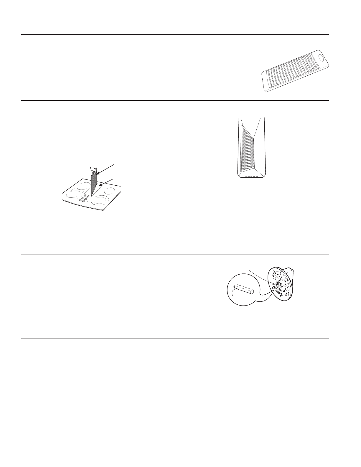
49-2001160 Rev. 0 11
Limpieza de la Placa de Cocción
Rejilla de ventilación
Antes de limpiar la rejilla de ventilación, asegúrese de que el
ventilador de salida esté apagado.
Para limpiar la rejilla de ventilación, quítela de la estufa
levantándola hacia arriba y afuera. Límpiela con un paño
húmedo. Si fuera necesario, la rejilla de ventilación puede
lavarse en el fregadero.
8WLOLFHOtTXLGRGHODYDSODWRVSDUDODYDU
1RXWLOLFHOLPSLDGRUHVDEUDVLYRV
Dañarán el acabado de la rejilla de
ventilación.
1RODYHODUHMLOODGHYHQWLODFLyQHQ
el lavaplatos.
Cámara y filtro de ventilación
El filtro es sostenido en su lugar en un ángulo con una
protuberancia de tope. Levante el filtro y extráigalo de la
abertura de ventilación diagonalmente.
Para limpiar el filtro, agítelo en agua caliente y enjabonada.
Enjuáguelo bien y séquelo completamente.
No opere la ventilación sin el filtro en su lugar.
Para limpiar la cámara de ventilación, use agua caliente y
HQMDERQDGD(QMXDJXHFRQDJXDOLPSLD\VHTXHELHQ1RXVH
limpiadores abrasivos; dañarán el acabado. Reemplace el filtro
después de que lo limpie y lo seque.
Remueva y reemplace el filtro
diagonalmente a través de la abertura de
ventilación.
Para ordenar filtros de reemplazo, lea las
secciones de Accesorios.
Vent
Chamber
Vent Filter
Cuando se encuentre reemplazando el filtro,
cerciórese de que descanse, en un ángulo, en
los soportes en la abertura de ventilación.
Superficies de Acero Inoxidable (en algunos modelos)
1RXVHYLUXWDVGHDFHURpVWDVGDxDUiQODVXSHUILFLH
Para limpiar la superficie de acero inoxidable, use agua tibia
con jabón o un limpiador o pulidor para acero inoxidable.
Siempre limpie la superficie en la dirección del veteado. Siga
las instrucciones del limpiador para limpiar la superficie de
acero inoxidable.
Para realizar consultas sobre la adquisición de productos,
incluyendo limpiadores o pulidores para electrodomésticos de
acero inoxidable, lea las secciones Accesorios.
CUIDADO Y LIMPIEZA: Limpieza de la Placa de Cocción
Botones de control
Las perillas de control pueden quitarse para limpiarse.
Para limpiar las perillas, cerciórese de que estén en la posición
GHDSDJDGR2))+DOHFDGDSHULOODKDFLDIXHUDGHOYiVWDJR
Para limpiar las perillas, colóquelos en un lavaplatos o realice
la limpieza con agua y jabón. Enjuague con agua limpia.
Asegúrese que los interiores de las perillas estén secos antes
de volver a colocarlas.
Cuando reemplace las perillas, revise que estén en la posición
GHDSDJDGR2))SDUDJDUDQWL]DUODFRORFDFLyQFRUUHFWD
Área
plana
Área plana moldeada
Los botones de control se pueden remover
para hacer su limpieza más fácil.
12 49-2001160 Rev. 0
Cómo Limpiar la Estufa de Vidrio
CUIDADO Y LIMPIEZA: Cómo Limpiar la Estufa de Vidrio
Superficie de Cocción de vidrio
Para mantener y proteger la superficie de su estufa de vidrio,
VLJDHVWRVSDVRV
1. Antes de usar la estufa por primera vez, límpiela con el
limpiador de estufas cerámicas. Esto ayuda a proteger la
estufa y hace la limpieza más sencilla.
2. El uso diario del limpiador de estufas cerámicas ayudará a
que la estufa quede como nueva.
3. Agite bien la crema de limpieza. Aplique unas gotas del
limpiador de estufas cerámicas directamente sobre la
estufa.
8WLOLFHXQDWRDOODGHSDSHORXQSDxRGHOLPSLH]DSDUD
estufas cerámicas para limpiar toda la superficie de la
estufa.
8VHXQSDxRVHFRRXQDWRDOODGHSDSHOSDUDTXLWDUORV
UHVWRVGHOOLPSLDGRU1RKDFHIDOWDHQMXDJDU
NOTA:(VPX\LPSRUWDQWHTXH12&$/,(17(ODHVWXIDKDVWD
que la haya limpiado por completo.
Limpie la estufa después
GHFDGDGHUUDPH8WLOLFH
el limpiador de estufas
cerámicas
Ceramic
Cooktop
Cleaner
Para acceder a videos de
limpieza e instrucciones,
escanee el código QR con su
dispositivo.
Residuos pegados
NOTA: Se podrán producir DAÑOS sobre la superficie de
vidrio si utiliza estropajos que no sean los recomendados.
1. Deje enfriar la estufa.
2. Coloque unas gotas del limpiador de estufas cerámicas
sobre toda el área de residuos pegados.
8WLOL]DQGRXQSDxRGHOLPSLH]DSDUDVXSHUILFLHVGHFRFFLyQ
de cerámica, frote el área sucia aplicando presión según
sea necesario.
4. Si quedan restos, repita los pasos indicados con
anterioridad.
5. Para protección adicional, después de haber quitado todos
los restos, pula toda la superficie con limpiador de estufas
cerámicas y una toalla de papel.
8WLOLFHXQSDxRGHOLPSLH]DSDUD
estufas cerámicas.
Residuos pegados rebeldes
1. Deje enfriar la estufa.
8WLOLFHHOUDVSDGRUGHILOR~QLFRDXQiQJXORDSUR[LPDGR
de 45 degrees contra la superficie del vidrio y raspe la
suciedad. Puede ser necesario aplicar presión al raspador
para quitar la suciedad.
3. Después de utilizar el raspador, coloque unas gotas de
limpiador de estufas cerámicas sobre toda el área de
VXFLHGDGTXHPDGD8WLOLFHHOSDxRGHOLPSLH]DSDUDTXLWDUOD
suciedad restante.
4. Para protección adicional, después de haber quitado todos
los restos, pula toda la superficie con limpiador de estufas
cerámicas y una toalla de papel.
La espátula para superficies de cocción de cerámica y todos los
elementos recomendados se encuentran disponibles a través de
nuestro Centro de Piezas. Consulte las secciones de Accesorios y
Soporte al Consumidor al final de este manual.
NOTA:1RXWLOLFHKRMDVGHVDILODGDVRGDxDGDV

49-2001160 Rev. 0 13
CUIDADO Y LIMPIEZA: Cómo Limpiar la Estufa de Vidrio
Cómo Limpiar la Estufa de Vidrio (Cont.)
Marcas de metal y rayones
1. Tenga cuidado de no deslizar ollas y sartenes a través de
su estufa. Dejará marcas de metal sobre la superficie de la
estufa.
Estas marcas pueden quitarse utilizando limpiador de
estufas cerámicas con el paño de limpieza para estufas
cerámicas.
2. Si se permite que ollas con una capa fina de aluminio
o cobre hiervan en seco, la capa puede dejar una
decoloración negra en la estufa.
Esto debe quitarse de inmediato antes de calentar de
nuevo o la decoloración puede llegar a ser permanente.
NOTA: Verifique con detenimiento que la base de las ollas no
sea áspera para no rayar la estufa.
3. Tenga cuidado de no colocar bandejas de horneado de
aluminio ni recipientes de platos principales congelados
de aluminio sobre una superficie caliente de la placa de
cocción. Éstas dejarán puntos brillantes o marcas sobre la
superficie de cocción. Estas marcas son permanentes y no
se podrán eliminar.
Daños por derrames azucarados y plástico derretido
Se deberá tener especial cuidado al eliminar sustancias calientes, a fin de evitar daños permanentes sobre la superficie de
vidrio./RVGHUUDPHVD]XFDUDGRVFRPRJHODWLQDVGXOFHFDUDPHORMDUDEHVRSOiVWLFRVGHUUHWLGRVSXHGHQPDUFDUODVXSHUILFLH
GHODHVWXIDQRFXELHUWRSRUODJDUDQWtDDPHQRVTXHHOGHUUDPHVHTXLWHPLHQWUDVHVWiFDOLHQWH'HEHWHQHUVHPXFKRFXLGDGRDO
remover sustancias calientes.
Asegúrese de utilizar un raspador nuevo y afilado.
1RXWLOLFHKRMDVGHVDILODGDVRGDxDGDV
1. Apague todas las unidades de superficie. Quite las ollas
calientes.
8WLOL]DQGRXQJXDQWHGHHVWXID
D8VHXQUDVSDGRUGHILOR~QLFRSDUDGHVSOD]DUHO
derrame a un área fría de la estufa.
b. Quite el derrame con toallas de papel.
3. Cualquier derrame restante debe dejarse hasta que la
superficie de la estufa se haya enfriado.
1RXVHODVXQLGDGHVGHVXSHUILFLHGHQXHYRKDVWDTXH
todos los restos se hayan eliminado por completo.
NOTA: Si la superficie de vidrio ya ha sufrido marcas o
hendiduras, el vidrio de la estufa deberá cambiarse. En ese
caso, será necesaria la atención de un técnico.
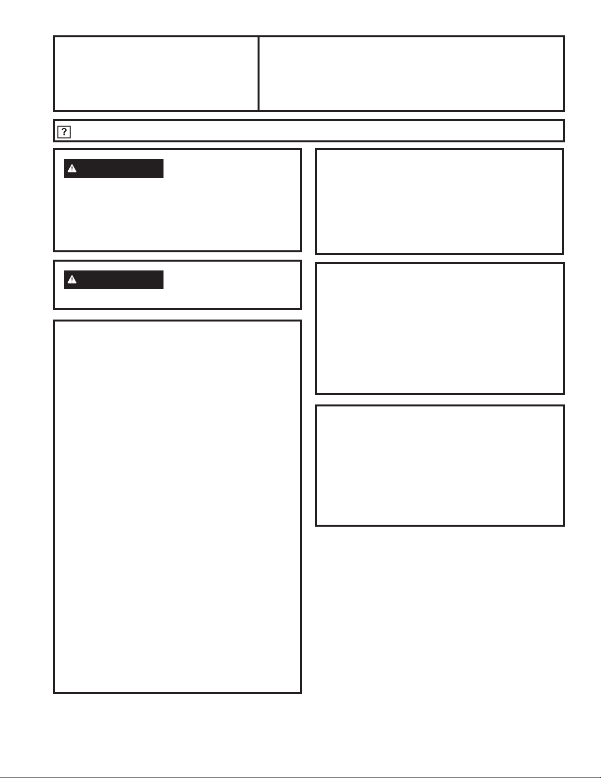
14 49-2001160 Rev. 0
Si tiene alguna pregunta, llame al 800.GE.CARES o visite nuestro sitio Web en: GEAppliances.com
Instrucciones
Estufa radiante de ventilación descendente
de Instalación
PP9830
ANTES DE COMENZAR
Lea estas instrucciones completa y cuidadosamente.
• IMPORTANTE
–
Guarde estas
instrucciones para ser usadas por el inspector local.
•
IMPORTANTE
–
Observe todos los
códigos y ordenanzas aplicables.
•
IMPORTANTE
–
Retire todo el
envoltorio, los materiales y las instrucciones, antes
de conectar el suministro de gas y electricidad a la
superficie de cocción.
•
IMPORTANTE
–
Para evitar daños
sobre los gabinetes, controle con su constructor o
proveedor de gabinetes que los materiales usados no
produzcan descoloración, deslaminado, ni generen
otros daños. Este electrodoméstico fue diseñado de
DFXHUGRFRQORVUHTXLVLWRVGH8/\&6$,QWHUQDWLRQDO\
cumple con las temperaturas máximas permitidas para
JDELQHWHVGHPDGHUDGH)&
• Nota al instalador – Cerciórese de dejar estas
instrucciones con el Consumidor.
• Nota al consumidor – Guarde estas instrucciones para
referencia futura.
• Servicio Técnico - El diagrama eléctrico está ubicado
dentro de la superficie de cocción.
• La instalación apropiada es la responsabilidad del
instalador.
• Si este producto falla por una instalación inapropiada, la
Garantía no cubrirá este producto.
CORTE DE LA ENCIMERA
Si instalará la superficie de cocción en una superficie
con un material sólido tal como granito, cuarzo u otra
superficie sólida natural o sintética, le recomendamos
que el corte sea realizado por un instalador profesional
de gabinetes o encimeras.
Los cortes de aberturas para superficies de cocción en
encimeras de madera o madera laminada se podrán
realizar usando un cierra de vaivén y un taladro eléctrico.
MATERIALES QUE PUEDE NECESITAR
• Cinta adhesiva de conductos
• Tornillos para hojas metálicas
• Trabajo de conductos que es apropiado para
la instalación
• Caja de Empalmes
• Abrazadera con amortiguador de refuerzo para
FRQGXFWRGHWDPDxRFRPHUFLDOGHò´
• Tuercas para cables
INSTRUCCIONES DE INSTALACIÓN
ADVERTENCIA
Antes de comenzar la
instalación, desconecte el interruptor de suministro
eléctrico en el panel de servicio y cierre el mecanismo
de seguridad para evitar que alguien lo conecte
accidentalmente. Cuando no exista un dispositivo de
cierre de seguridad, amarre un aviso visible, como una
etiqueta al panel de servicio haciendo la advertencia.
ADVERTENCIA
Para reducir el riesgo de
incendios, use sólo conductos metálicos.
HERRAMIENTAS QUE NECESITARÁ
• Gafas de Seguridad
• Sierra
• Pencil
• Cinta métrica o escala
• Escuadra de carpintero
• Pinza de Electricista
• Llave ajustable o juego
GHFXERV´FXER
de y trinquete)
• Taladradora y broca
/ODYHGHWXHUFDVGH´
• Destornillador con
cabeza plana
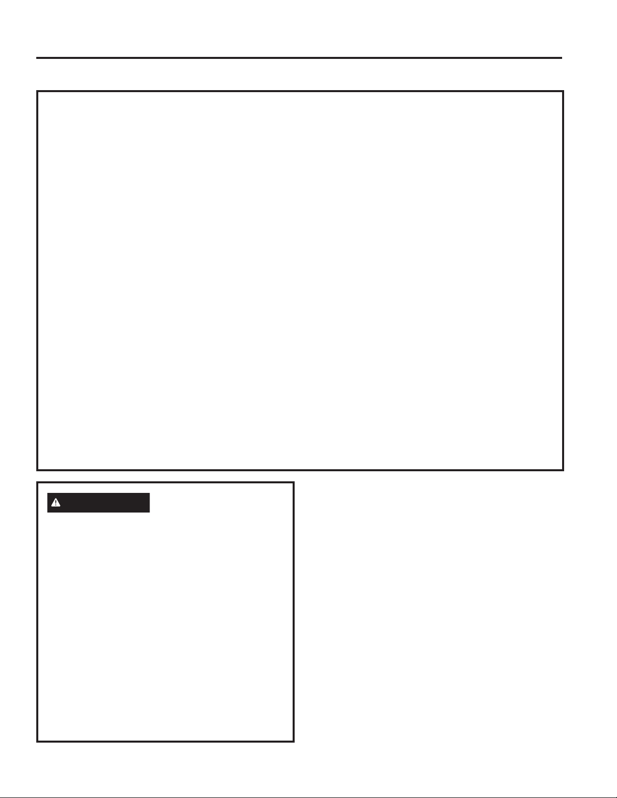
49-2001160 Rev. 0 15
INSTRUCCIONES DE INSTALACIÓN
Instrucciones de Instalación
INSTRUCCIONES DE SEGURIDAD IMPORTANTES
La estufa es un diseño que ha sido certificado por la
$VRFLDFLyQ1RUWHDPHULFDQDGH*DV&RPRVXFHGH
con cualquier aparato que genere calor, hay ciertas
precauciones de seguridad que debe seguir. Encontrará
estas precauciones en la sección Instrucciones importantes
de seguridad en esta manual. Léala detenidamente.
• Asegúrese de que la estufa sea instalada adecuadamente
por un técnico calificado o un técnico en servicio.
• La estufa debe tener conexión a tierra de acuerdo con los
códigos locales, o en ausencia de éstos, con el Código
(OpFWULFR1DFLRQDO$16,1)3$1RRHO&yGLJRGH
(OHFWULFLGDGGH&DQDGi&DQDGLDQ(OHFWULF&RGH&6$
&
• La instalación, el ajuste, la alteración, el servicio o
mantenimiento incorrectos pueden causar lesiones
o daños a la propiedad. Consulte este manual. Para
asistencia o información adicional, consulte a un instalador
FDOLILFDGRDJHQWHGHVHUYLFLRIDEULFDQWHGLVWULEXLGRURDO
abastecedor de gas.
• Desconecte el suministro eléctrico antes de dar servicio al
aparato.
• A fin de eliminar el riesgo de quemaduras debido a que
se alcanzaron elementos sobre superficies calientes, se
deberá evitar el uso del espacio de almacenamiento del
gabinete ubicado sobre las unidades. De ser necesario
proveer espacio para el gabinete de almacenamiento, el
riesgo se puede reducir instalando una campana de salida
de aire con proyección horizontal a un mínimo de 5“ desde
la parte inferior de los gabinetes. Los gabinetes instalados
sobre la superficie de cocción no deberán poseer una
SURIXQGLGDGVXSHULRUDODV´
• Asegúrese de que los recubrimientos de las paredes que
están alrededor de la estufa resistan el calor generado por
ODHVWXIDKDVWD)&
6LXQDWROHUDQFLDGH´HQWUHODVXSHUILFLHGHFRFLQD\HO
material combustible encima de la estufa o los gabinetes
metálicos no pueden mantenerse, proteja la parte de abajo
de los gabinetes que se encuentran en la parte superior
GHODHVWXIDFRQQRPHQRVGH»´PPGHFDUWyQ\
DLVODQWHROiPLQDGH\HVRGHDOPHQRV»´PP
cubierta con una hoja de metal de calibre 28 o de cobre
´PPGHHVSHVRU
• La distancia entre la superficie para cocinar y los
JDELQHWHVSURWHJLGRV181&$'(%(6(50(12548(
38/*$'$6FP/DGLVWDQFLDYHUWLFDOGHVGH
la superficie para cocinar hasta la parte inferior de los
gabinetes adyacentes superiores que se extienden más de
´FPDORVODGRVGHOSODQRGHODHVWXIDQRGHEHVHU
PHQRUGH´FP
• Al cortar o perforar sobre paredes o cielorrasos, no dañe el
cableado eléctrico y otros conductos de servicios ocultos.
• Los ventiladores con conducto siempre deberán poseer
ventilación hacia el exterior.
ADVERTENCIA
ADVERTENCIA
DE SEGURIDAD DEL SOPLADOR DE
ESCAP
Es necesario contar con suficiente cantidad de aire para
una combustión y salida de gases adecuadas a través
GHOFRQGXFWRFKLPHQHDGHOHTXLSRGHFRQVXPRGH
combustible, a fin de evitar descargas. Siga las pautas
del fabricante del equipo de calefacción y los estándares
de seguridad, tales como aquellos publicados por la
$VRFLDFLyQ1DFLRQDOGH3URWHFFLyQFRQWUD,QFHQGLRV
1DWLRQDO)LUH3URWHFWLRQ$VVRFLDWLRQ1)3$OD
6RFLHGDG(VWDGRXQLGHQVHSDUDOD&DOHIDFFLyQ$PHULFDQ
6RFLHW\IRU+HDWLQJORV,QJHQLHURVGH5HIULJHUDFLyQ
\$FRQGLFLRQDGRUHVGH$LUH5HIULJHUDWLRQDQG$LU
&RQGLWLRQLQJ(QJLQHHUV$6+5$(\ODVDXWRULGDGHV
de los códigos locales. Cuando corresponda, instale un
VLVWHPDGHUHSRVLFLyQUHHPSOD]RGHDLUHGHDFXHUGR
con los requisitos del código local de construcción. Para
acceder a soluciones relacionadas con la reposición de
aire, visite GEAppliances.com.
16 49-2001160 Rev. 0
REQUISITOS ELÉCTRICOS
Este electrodoméstico debe suplirse con el voltaje y
la frecuencia apropiados, conforme se indica en estas
Instrucciones de Instalación, y debe ser conectado a un
ramo eléctrico conectado apropiadamente a tierra, protegido
por un interruptor de circuito de 40 amperios o fusibles de
dilatación de tiempo.
Todas las conexiones de alambres deben hacerse
de acuerdo con los códigos locales y deben estar
apropiadamente aisladas. Póngase en contacto con la
compañía de utilidades local para los códigos eléctricos
y ordenanzas de su gobierno. En la ausencia de códigos
HOpFWULFRVORFDOHVHO1DWLRQDO(OHFWULFDO&RGH$16,1)3$
1R±HQVXPiVUHFLHQWHHGLFLyQTXHJRELHUQDOD
instalación de estufas eléctricas, deben seguirse.
8VWHGSXHGHREWHQHUXQDFRSLDGHO1DWLRQDO(OHFWULFDO&RGH
HVFULELHQGRD
1DWLRQDO)LUH3URWHFWLRQ$VVRFLDWLRQ
%DWWHU\PDUFK3DUN
Quincy, MA 02260
(IHFWLYRHOGHHQHURGHHO1DWLRQDO(OHFWULFDO
Code requiere que las construcciones nuevas, pero no
ya existentes, utilicen conexiones de cuatro conductores
para estufas eléctricos. Cuando se encuentre instalando
una estufa eléctrica en una construcción nueva, siga las
LQVWUXFFLRQHVHQ&216758&&,Ï118(9$<&21(;,Ï1
'(5$0$/'(&,5&8,72'(&8$752&21'8&725(6
8VWHGGHEHXVDUXQVLVWHPDHOpFWULFRGHFDEOHVGHWUHV
alambres, de fase sencilla AC 208Y/120 voltios o 240/120
YROWLRV+HUW]FRQFRQH[LyQDWLHUUDSRUVHSDUDGR
Si usted conecta a alambres de aluminio, debe usar
conectadoras aprobados para el uso con alambrado de
aluminio.
Instrucciones de Instalación
ADVERTENCIA
Para su seguridad personal,
retire el fusible del hogar o abra el disyuntor antes
de comenzar la instalación. Si esto no se cumple,
se podrán sufrir lesiones graves o la muerte.
INSTRUCCIONES DE INSTALACIÓN
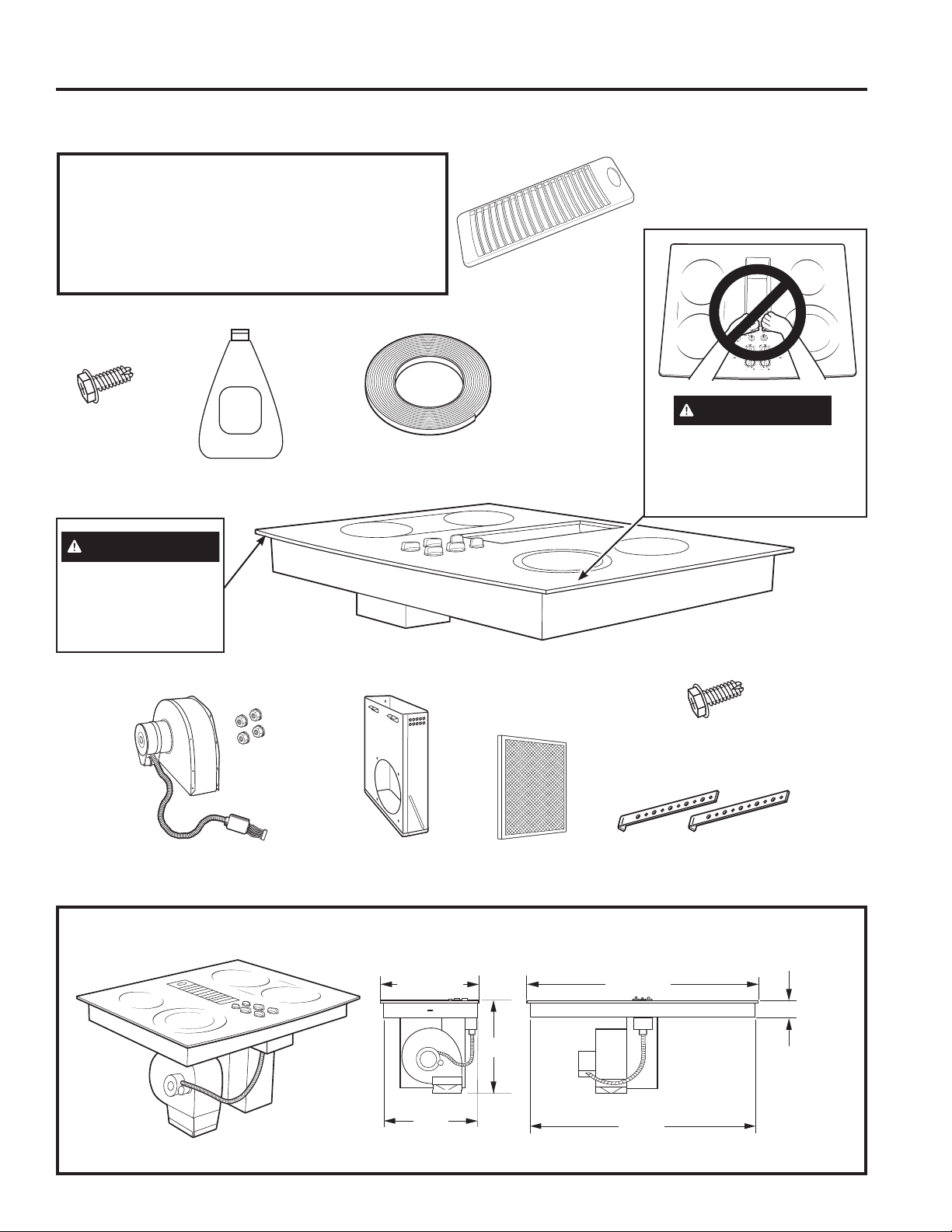
49-2001160 Rev. 0 17
INSTRUCCIONES DE INSTALACIÓN
Instrucciones de Instalación
DESEMPACANDO SU ESTUFA
Asegúrese que todos los materiales de empaque y cintas
se hayan retirado. Esto incluye cintas sobre las perillas de
FRQWUROVLFRUUHVSRQGHFLQWDDGKHVLYDFLQWDVGHDMXVWH
cartón y plástico protector. Si estos materiales no se
retiran se puede producir como resultado un daño sobre el
electrodoméstico, una vez que el mismo fue encendido y
las superficies se calientan.
Rejilla de ventilación
Crema de limpieza
Tornillos
de plancha
PHWiOLFD
[´
Cinta de junta de espuma
UROORGHSLHV
Ensambladura del soplador y tuercas
GHPRQWDMHWXHUFDV²FRQVXV
arandelas de cierre pegadas)
Pleno del
soplador
Filtro del
ventilador
Ceramic
Cooktop
Cleaner
Tornillos para
plancha metálica
[´
Soportes de
6XVSHQVLyQ
ESTUFA DE 30” (DIMENSIONES PARA REFERENCIA SOLAMENTE)
La unidad se muestra totalmente ensamblada.
La unidad debe tener ventilación hacia el exterior!
20
1
»2´
´
28
3
»4´
2
1
»2´
9
»16´66
21
7
»8´
15
»16´66
29
3
»4´
13
»16´66
PRECAUCIÓN
12/(9$17(325
/$$%(5785$'(
9(17,/$&,Ï12&+248(
EL VIDRIO
PRECAUCIÓN
EL VIDRIO ES FRÁGIL
NO CHOQUE LA
ESQUINAS DEL VIDRIO
DURANTE
LA INSTALACIÓN
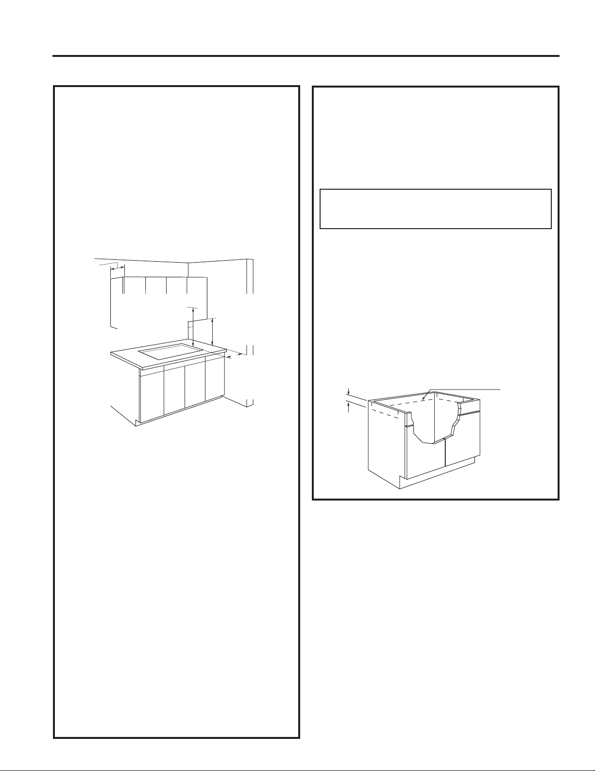
18 49-2001160 Rev. 0
Instrucciones de Instalación
PREPARACIÓN DE LA INSTALACIÓN
1. PREPARACIÓN PARA LA
INSTALACIÓN
Posicionamiento de la superficie de
cocción
La estufa está diseñada para lucir mejor cuando está
FHQWUDGDHQXQJDELQHWHGHSRUORPHQRV´GHDQFKR
La ventanilla de escape debajo de la estufa debe estar
localizada entre los bajantes de la pared o entre las vigas
del piso de forma que el trabajo de conductos pueda ser
instalado apropiadamente.
Por lo menos 5 1/2" se deben dejar entre los extremos
laterales de la estufa y las paredes adyacentes.
Evite colocar gabinetes encima de la unidad, si es
posible, para reducir los peligros causados por tener que
intentar alcanzar unidades de superficie calentadas. Si
los gabinetes están colocados encima de la estufa, los
riesgos se pueden reducir instalando una capucha de
estufa que proyecte horizontalmente un mínimo de 5
pulgadas más allá del fondo de los gabinetes.
Si se usan gabineterías encima de la estufa, deje una
tolerancia mínima de 30" entre la superficie de cocina y el
fondo de cualquier gabinete no protegido.
Si la tolerancia entre la estufa y la gabinetería es menor
de 30", el gabinete debe protegerse con una plancha
retardante de llamas de por lo menos 1/4" de grueso,
cubierta con una plancha metálica de acero calibre 28 o
con una pancha de cobre de 0.020". La tolerancia entre
ODHVWXID\ODJDELQHWHUtDSURWHJLGD181&$'(%(6(5
0(125'(
((;&(3&,Ï1/DLQVWDODFLyQGHXQKRUQRGHPLFURRQGDV
especificado o de un electrodoméstico de cocina sobre
una estufa debe conformarse a las instrucciones de
instalación empacadas con ese electrodoméstico.
15" mínimas deben dejarse a partir de cada lado de
extremo de la estufa hasta el fondo de cualquier gabinete
no directamente colocado sobre la estufa. Si la tolerancia
es menor de 15", los gabinetes adyacentes deben ser de
por lo menos 5 1/2" desde el lado extremo de la estufa.
INSTRUCCIONES DE INSTALACIÓN
2. PREPARACIÓN DEL GABINETE
DE LA BASE
Esta estufa está diseñada para ajustar fácilmente en
una variedad de gabinetes. Sin embargo, la instalación
combinada de una estufa y ventilación descendente
requiere consideración cuidadosa.
Algunos gabinetes podrían requerir modificaciones.
Esta instalación requiere un gabinete de base de una
SURIXQGLGDGPtQLPDGH´(OJDELQHWHGHEHVHUGHSRU
ORPHQRV´GHDQFKR
Preparando un gabinete que ajuste contra la pared
En algunos gabinetes, los lados podrían necesitar ser
UHEDMDGRVRFRUWDGRV»´FRPRVHPXHVWUDHQOD
figura, y las abrazaderas de las esquinas removidas para
acomodar la unidad.
En gabinetes europeos sin forma de 75 cm y 90 cm, el
SDQHOSRVWHULRUSRGUtDQHFHVLWDUVHUUHEDMDGRKDVWD»´
para acomodar la unidad.
Preparando un gabinete tipo península o tipo isla
En gabinetes tipo península o isla, los lados podrían
necesitar ser rebajados o cortados, y las abrazaderas de
las esquinas removidas para acomodar la unidad.
Aprox.
»
Para gabinetes
europeos
DSUR[»
La
profundidad
del área
elevada de
los gabinetes
debe ser de
un máximo de
13"
Tolerancia
mínima de 6" a
partir del corte
hasta las paredes
laterales.
Tolerancia mínima
de 30" a partir de la
encimera hasta la
superficie elevada
no protegida.
Altura mínima de 15"
desde la encimera
hasta el gabinete
más cercano en
cualquiera de los
lados de la unidad.
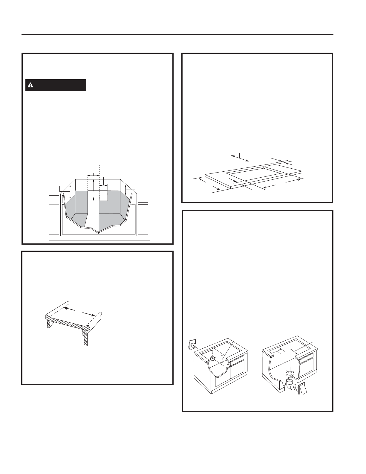
49-2001160 Rev. 0 19
INSTRUCCIONES DE INSTALACIÓN
PREPARACIÓN DE LA INSTALACIÓN (Cont.)
Instrucciones de Instalación
3. PREPARACIÓN RÁPIDA DE UNA
CAJA DE UNIÓN
PRECAUCIÓN
PARA SEGURIDAD PERSONAL,
REMUEVA EL FUSIBLE DE LA CASA O ABRA EL
INTERRUPTOR DE CIRCUITO ANTES DE PREPARAR
LA CAJA DE UNIÓN.
Instale una caja de unión aprobada dentro del área
sombrada en el diagrama que se muestra en la ilustración.
/DFDMDGHXQLyQSXHGHHVWDUDSRUORPHQRV»GHO
gabinete superior.
Pase los conductores desde el alambrado de la residencia
hasta la caja de unión de acuerdo con los códigos
eléctricos.
16"
9"
4"
´
10
1
»2´
C
L
4. PREPARANDO LA ENCIMERA
La encimera debe tener una superficie plana profunda
para acomodar la estufa y la ventilación. Las encimeras
FRQXQH[WUHPRIURQWDOURGDGR\³EDFNVSODVK´SXHGHQR
proporcionar el área de superficie plana requerida.
8QiUHDSODQDGH´GHDQFKRVHUHTXLHUHDOUHGHGRUGHO
extremo de la abertura para soportar la unidad. La unidad
debe ser nivelada y sentarse derecha en la abertura de la
encimera.
Área de superficie plana de un mínimo
UHTXHULGRGH´
4. PREPARANDO LA ENCIMERA
(Cont.)
Con cuidado corte la abertura de la encimera de acuerdo
con las dimensiones mostradas en la ilustración.
Cerciórese de que la abertura es cortada derecha, con
los lados paralelos entre sí y con la parte posterior
exactamente perpendicular a los lados.
Para la instalación de la isla, deje un espacio mínimo
GH´GHVGHODDEHUWXUDKDVWDHOH[WUHPRIURQWDOXQ
HVSDFLRPtQLPRGH´GHVGHODDEHUWXUDKDVWDHO
H[WUHPRWUDVHUR\XQHVSDFLRPtQLPRGH´GHVGHOD
abertura hasta los extremos laterales de la encimera.
20 5/8" ±1/8"
1 7/8"min.
25"
28 7/8" ±1/8"
2 3/8" min.
5. PREPARACIONES PARA LOS
CONDUCTOS
NOTA: (OWUDEDMRGHFRQGXFWRV'(%(WHQHUYHQWLODFLyQ
KDFLDHOH[WHULRU129(17,/(KDFLDODVSDUHGHVWHFKR
esquinas, áticos o cualquier otro lugar cerrado.
Corte un agujero en la pared del gabinete o en el piso
del gabinete según sea apropiado para su instalación.
Cerciórese de que los tubos de escape están localizados
entre los bajantes de la pared o las vigas del piso.
NOTA: Cuando se encuentre cortando o taladrando en la
pared o en el techo, no dañe los alambrados eléctricos u
otras utilidades escondidas. Asegúrese de que cualquier
abertura en la pared detrás del electrodoméstico y en el
piso debajo del electrodoméstico esté sellada de forma
apropiada.
9
1
»8
´
18
3
»4
´
10
1
»8
´
6
1
»8
´
Ventilación de la pared
posterior
Ventilación vertical
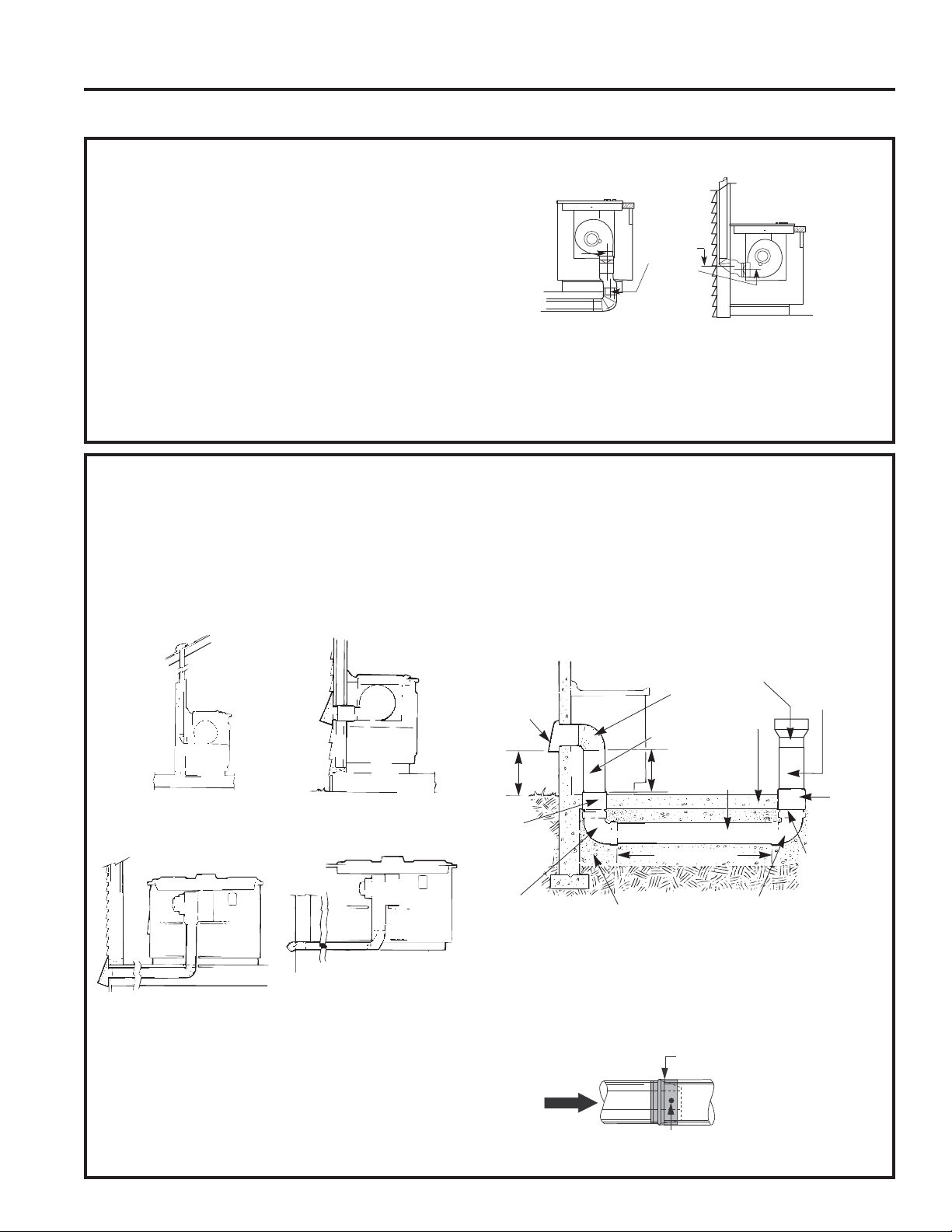
20 49-2001160 Rev. 0
PREPARACIÓN DE LA INSTALACIÓN (Cont.)
Instrucciones de Instalación
6. ALINEACIÓN DE LOS CONDUCTOS DEL SOPLADOR
En general, no instamos al uso de conductos flexibles
porque éste puede causar severas restricciones del
flujo de aire. Sin embargo, si la salida del soplador y la
localización en la pared o en el piso representa un problema
de alineación, entonces usted puede usar conductos
0(7È/,&26SDUDDGDSWDUODFRPSHQVDFLyQ8QEXHQ
centramiento sin necesidad de conductos flexibles es lo
preferido.
NOTA:
1RH[FHGDODDGDSWDFLyQPi[LPDUHFRPHQGDGDGH
1RSHUPLWDTXHHOFRQGXFWRIOH[LEOHVHGREOHRTXH
colapse.
• Alargue el conducto flexible tanto como sea posible para
evitar la corrugación tanto como sea posible.
8QUHFWiQJXORGH»´[´DXQDWUDQVLFLyQGHFRQGXFWR
UHGRQGRGH´HVWiGLVSRQLEOHHQVXWLHQGDGHVXPLQLVWURV
para construcción local.
NOTA: Las ilustraciones son simplemente para que usted
planifique.
INSTRUCCIONES DE INSTALACIÓN
6" Máximas
desde la
línea central
hasta
la línea
central de
adaptación
Ventilación trasera
5HTXLHUH»[
Ventilación de fondo
7. PREPARACIÓN DEL CONDUCTO
Determine el mejor recorrido para el conducto; el mismo
puede ser conducido de diferentes formas dependiendo del
esquema de la cocina.
IMPORTANTE/DVDOLGDGHODGHVFDUJDGHDLUH
descendente para esta unidad es rectangular, y con una
PHGLGDGH´[´3ODQLILTXHHOUHFRUULGRGHIRUPD
consecuente.
Serie de mesadas con distribución típica de tuberías.
A fin de maximizar el rendimiento de la ventilación del
VLVWHPDGHYHQWLODFLyQ
1. Minimice la longitud del conducto y el número de
transiciones y codos.
2. Mantenga un tamaño de tubería constante.
3. Selle todas las juntas con cinta para conductos a fin de
evitar pérdidas.
1RXWLOLFHWXEHUtDVIOH[LEOHVGHQLQJ~QWLSR
De ser necesario, instale un sistema de reposición
UHHPSOD]RGHDLUHGHDFXHUGRFRQORVUHTXLVLWRVGHO
código local de construcción. Para acceder a soluciones
relacionadas con la reposición de aire,
visite GEAppliances.com.
• Arreglo opcional del conducto bajo una losa de concreto
Se deberá usar un conducto de PVC si se instalará bajo
una losa de concreto.
• Instale la tubería de modo que el trozo de conducto más
FHUFDQRDODXQLGDGGHVFHQGHQWHHQFDMH'(1752'(OD
siguiente pieza del conducto. Asegure las uniones con
tornillos autorroscantes y coloque cinta para conductos
alrededor de las uniones, a fin de sellar la salida de aire.
Pared interna
del gabinete
Pared interna hacia arriba
hasta el techo o parte saliente
Directamente hacia el exterior
Entre vigas del piso A través del espacio de las
patas del gabinete
Península o isla
Península
Pared externa
del gabinete
NOTA: Tubería de PVC tipo cloaca PSM 12454-B
Lista 40 ASTM D1785.
Tapa de
Pared
Losa de
Concreto
Tubería para
Cloaca de
PVC de 6”
(15 cm.) de Diá.
Conducto Metálico
de
6” (15 cm.) de Diá.
Embale de forma bien
ajustada con grava o arena
completamente
alrededor de la tubería
Transición Rectangular de
3 ¼” x 10” a Circular de 6”
Codo Metálico
de 90º de 6”
(15 cm.) de Diá.
6” (15 cm.) Diá.
Conducto Metálico
16”
(40.6 cm.)
de Máx.
12”
(30 cm.)
Mín.
Unión de
PVC de 6”
(15 cm.) Diá.
Codo para Tubería
de Cloaca de PVC
de 6” (15 cm.) de Diá.
Codo para Tubería
de Cloaca de
6” (15 cm.) de Diá.
Tubería de
Cloaca
de PVC de
6” (15 cm.)
de Diá.
Unión de
PVC de 6”
(15 cm) de Diá.
30’-0” (9.14 m.) Max.
Cinta para Conducto sobre
la Unión y el Tornillo
Tornillo
Aire
Flujo
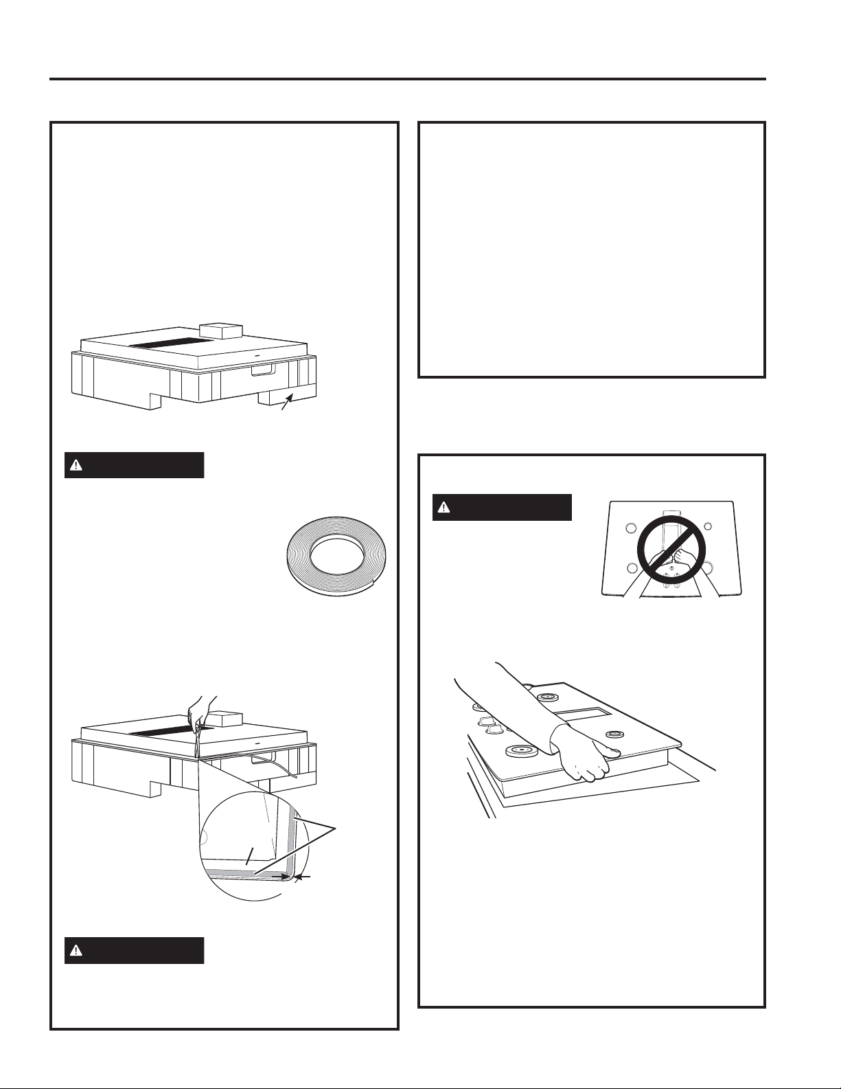
49-2001160 Rev. 0 21
INSTRUCCIONES DE INSTALACIÓN
PREPARACIÓN DE LA INSTALACIÓN (Cont.)
Instrucciones de Instalación
9. CÓMO INSTALAR LA ESTUFA
PRECAUCIÓN
12/(9$17(325
/$$%(5785$'(
9(17,/$&,Ï1
Levante la estufa por los
extremos del lado del
vidrio como se muestra.
NOTA: 1RXVHODDEHUWXUDGHYHQWLODFLyQSDUD
levantar o mover la estufa de posición.
%DMHODHVWXIDKDFLDODDEHUWXUDHQODHQFLPHUD
guiándola hasta llegar a su posición. El vidrio es
IUiJLO²QRSHUPLWDTXHVHFDLJDVREUHODHQFLPHUD
Apoye desde el lado inferior y baje con cuidado.
Cuidadosamente remueva sus dedos de una
esquina a la vez para bajar la estufa hasta su
posición.
8QDYH]XELFDGDODXQLGDGHQODPHVDGD
inspeccione visualmente el aspecto o la alineación
de la superficie de cocción y la mesada.
CÓMO INSTALAR LA ESTUFA
8. CÓMO INSTALAR LA JUNTA DE
ESPUMA
1RLQVWDOHODHVWXIDHQODHQFLPHUDVLQKDEHULQVWDODGR
la junta de espuma como se muestra. Esta protege el
extremo inferior del vidrio de la encimera y sella la estufa
contra derrames.
Remueva la estufa junto a sus almohadillas de empaque
de la caja de envío. Remueva el bloque de envío de
ODDEHUWXUDGHYHQWLODFLyQGHVFHQGHQWHGRZQGUDIW
y colóquela debajo de la almohadilla de envío para
proporcionar apoyo de nivel.
PRECAUCIÓN
(/9,'5,2(6)5È*,/12*2/3((/26(;75(026
'(/9,'5,2'85$17(/$,167$/$&,Ï1
Localice le cinta de junta de espuma
incluida con su estufa.
Pula los extremos ásperos en el corte.
Pele la parte posterior blanca para
instalar la cinta de la junta de espuma
en el lado del fondo del vidrio de la estufa.
Notas sobre la instalación de la junta de espuma:
• La cinta de junta de espuma debería ser instalada
GHQWURGH´GHOH[WUHPRGHOYLGULR1RDODUJXHR
doble la cinta de junta de espuma.
PRECAUCIÓN
1RLQVWDODUODFLQWDGHMXQWDGH
espuma aumenta el potencia de que el vidrio de la estufa
se rompa cuando se esté instalando, especialmente en
encimeras Corian® o de granito.
Centre el bloque de envío de la ventilación
debajo de la almohadilla de envío para
proporcionar apoyo de nivel.
Lado inferior
del vidrio
Cinta de
junta de
espuma
1
»8
´
máximo al
extremo del
vidrio
8. CÓMO INSTALAR LA JUNTA DE
ESPUMA (Cont.)
8VHFXLGDGRH[WUHPRGHQRDODUJDUODFLQWDGHMXQWDGH
espuma mientras la instala o no permanecerá en su
lugar.
1RFRORTXHODFLQWDGHMXQWDGHHVSXPDVREUHORV
bordes metálicos.
• Empalme los extremos de la cinta de junta de espuma
en cada esquina sin que una quede encima de la otra.
• Cubra todo el marco con la cinta de junta de espuma
sin alargarla.
•
Corte las esquinas externas de la cinta de junta de espuma
ligeramente si fuera necesario para que luzca bien.
1RUDVJXxHHOYLGULRPLHQWUDVFRUWDODFLQWDGHMXQWDGH
espuma.
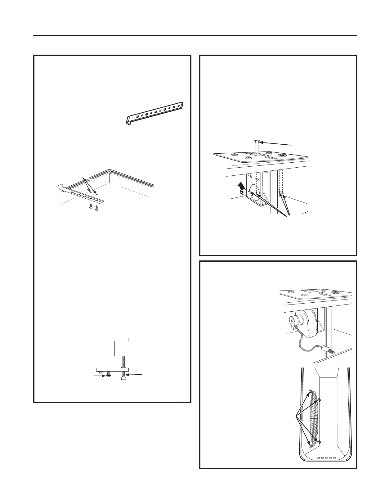
22 49-2001160 Rev. 0
Instrucciones de Instalación
CÓMO INSTALAR LA ESTUFA (Cont.)
INSTRUCCIONES DE INSTALACIÓN
10. CÓMO INSTALAR LA ESTUFA
A. Asegúrese de que el extremo frontal de la encimera
TXHGHSDUDOHORDODVXSHUILFLHGHFRFFLyQ+DJDHO
control final para verificar que se cumpla con todos los
espacios libres necesarios.
%8ELTXH\UHWLUHORVVRSRUWHVGH
suspensión del paquete del kit
de instalación.
C. Adhiera los soportes sobre
el lado inferior de la superficie de cocción. Retire los
tornillos de la parte inferior de la superficie de cocción
y atornille el soporte de suspensión a la parte inferior
de la unidad de la superficie de cocción. Repita este
paso en el lado opuesto de la superficie de cocción.
D. Atornille el soporte sobre los costados del gabinete
para asegurar la unidad en su ubicación.
Instalación Alternativa:
8VWHGSXHGHRUGHQDUHONLWGHLQVWDODFLyQDOWHUQDWLYR
:%;FRQWXHUFDVPDULSRVD\VRSRUWHVOODPDQGR
al 800.GE.CARES. Consulte el diagrama para acceder a
instrucciones.
3DUDFRORFDUVRSRUWHVGHLQVWDODFLyQRSFLRQDOHV
Quite los 2 tornillos a ambos lados bajo la estufa.
Alinee el soporte de instalación opcional bajo la estufa y
reinstale los tornillos a través de la ranura del soporte.
+DJDHVWRHQDPERVODGRVGHODHVWXID
Introduzca el tornillo de apriete a través del orificio del
soporte y ajuste para fijar la estufa al mostrador de
encimera. Repita en el otro lado.
IMPORTANTE: Gire el tornillo de apriete hasta que toque
ODSDUWHLQIHULRUGHODHVWXID1RDMXVWHGHPiV
Placa de
Cocción
Encimera
Tornillos provistos con
la superficie de cocción
Tornillos
mariposa
Agujeros preperforados
Parte inferior de la
Superficie de Cocción
%DVHGHOD6XSHUILFLH
de Cocción
11. CÓMO INSTALAR LA CÁMARA
DEL SOPLADOR DE LA
ESTUFA
Deslice la cámara, con la abertura del soplador del lado
izquierdo, en la abertura en el fondo de la estufa. Empuje
la cámara hasta que se detenga cuando la cámara haga
contacto con el fondo de la estufa, y la cámara encaje
HQVXOXJDU(VSRVLEOHTXHXVWHGWHQJDTXHPRYHUOD
cámara hacia adelante y hacia atrás para encontrar su
lugar exacto.)
Asegure la cámara al fondo de la estufa, en cada lado,
XVDQGRORVFXDWURWRUQLOORVSURSRUFLRQDGRV/XHJR
asegure la cámara a la estufa, a partir del lado superior,
XVDQGRORVGRVWRUQLOORVSURSRUFLRQDGRV
12. CÓMO INSTALAR LA CÁMARA
DEL SOPLADOR
Oriente la abertura de
descarga del soplador hasta
que iguale el conducto en
los Pasos 6 y 7. Deslice las
cuatro tachuelas roscadas
en el lado del alojamiento
del soplador en los cuatro
agujeros en el lado de la
cámara.
NOTA: Ver el Paso 13 para
la instalación del conducto
de transición del soplador.
Es posible que sea más
fácil instalar el conducto
de transición al soplador
antes de instalar el
soplador a la cámara.
A partir de la abertura de
ventilación en la parte
superior de la estufa,
apriete la ensambladura
del soplador de manera
firme a la cámara con
FXDWURWXHUFDV
4 tuercas
VH
necesita
un cubo de
tuercas de
´
Instale 2 tornillos
Instale 4 tornillos
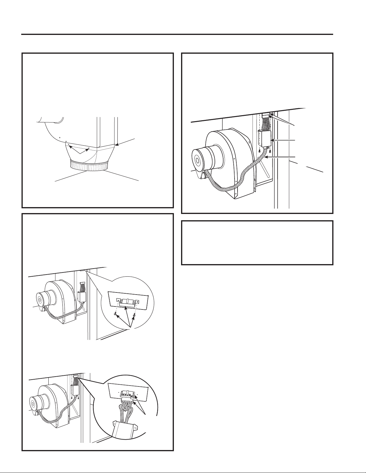
49-2001160 Rev. 0 23
INSTRUCCIONES DE INSTALACIÓN
Instrucciones de Instalación
CÓMO INSTALAR LA ESTUFA (Cont.)
14. CONEXIONES ELÉCTRICAS
DEL SOPLADOR
• Afloje los dos tornillos y remueva y descarte la cubierta
del conectador metálico en el fondo de la estufa.
Guarde los tornillos para la reinstalación que vendrá
más tarde.
• Conecte el tapón de 5 pasadores en la ensambladura
para combinar con el receptáculo de 5 pasadores en el
fondo de la estufa.
15. CONEXIONES ELÉCTRICAS
DEL SOPLADOR (CONT.)
• Doble todos los alambres en el alojamiento eléctrico.
Asegure el alojamiento con los tornillos removidos
anteriormente, cerciorándose de que no quedaron
alambres atrapados.
16. CÓMO CONECTAR LOS
CONDUCTOS
Conecte la tubería preparada en los Pasos 6 y 7 al
extractor.
Quite los
tornillos y
descarte la cinta
Conectores
de 5
pasantes
Conectores
de 5
pasantes
Alojamiento
eléctrico
Conducto
flexible
13. CÓMO PEGAR UNA
TRANSICIÓN DE SOPLADOR
8VHXQFRQGXFWRGHWUDQVLFLyQGHVRSODGRUSDUDWRGDVODV
instalaciones de conductos de flujo de aire descendente
SDUDFRQHFWDUODVSLH]DVGHFRQGXFWRGH´UHGRQGDV
(VWHUHFWiQJXORGH»´[´DFRQGXFWRGH´UHGRQGR
de transición está disponible en su ferretería local.
Instale el conducto de transición a la salida del soplador.
Asegure toda las juntas con cinta adhesiva de conducto
para asegurar hermeticidad.
Tornillos
Tornillo
HQHORWUR
lado)
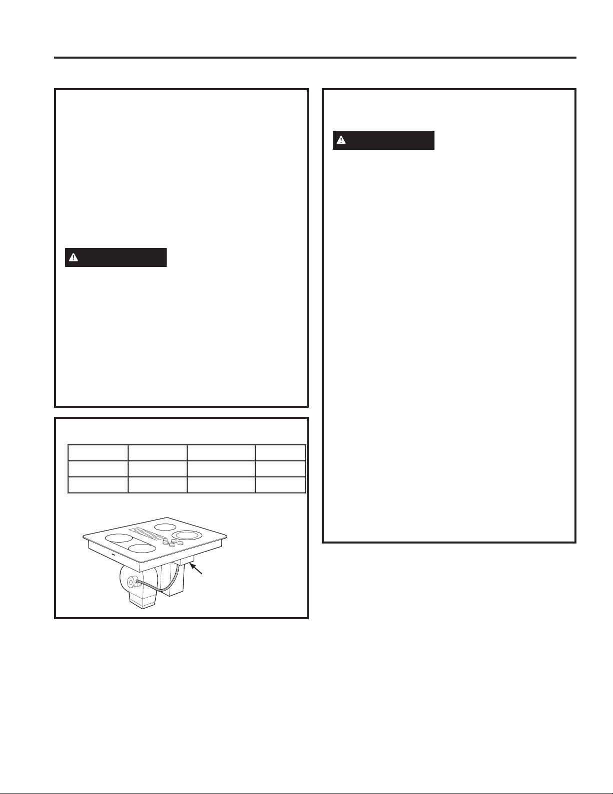
24 49-2001160 Rev. 0
Instrucciones de Instalación
CÓMO INSTALAR LA ESTUFA (Cont.)
17. ANTES DE HACER
CONEXIONES ELÉCTRICAS
Nota al electricista: Los conductores proporcionados
FRQHVWHHOHFWURGRPpVWLFRVRQUHFRQRFLGRVSRUOD8/
para conexiones eléctricas residenciales de calibres
altos.
El aislamiento de estos conductores es considerado
a temperaturas mucho mayores que las esperadas
en residencias. La capacidad de carga actual de un
conductor es determinado por el calibre del cable y
también por la temperatura considerada del aislamiento
alrededor del cable.
ADVERTENCIA
Alambre de aluminio -
UNA CONEXIÓN DEL ALAMBRE DE ALUMINIO
RESIDENCIAL INAPROPIADA A CONDUCTORES DE
COBRE PUEDE RESULTAR EN PROBLEMAS SERIOS.
8QDORVDODPEUHVGHDOXPLQLR\ORVDODPEUHVGHFREUH
usando conectadores especialmente diseñados y
UHFRQRFLGRVSRU8/SDUDXQLUFREUH\DOXPLQLR6LJDHO
procedimiento recomendado por el fabricante de los
conectadores muy de cerca.
Onda de servicio – Deje una onda en el alambre de la
estufa de forma tal que la estufa pueda ser levantada 12
pulgadas sin tener que desconectarse del alambrado.
REQUISITOS ELÉCTRICOS*
)RUUHIHUHQFHRQO\9HULI\ZLWKSURGXFWUDWLQJSODWH
Plato de
especificación
18. CÓMO HACER LAS
CONEXIONES ELÉCTRICAS
ADVERTENCIA
Apague el interruptor del
panel del servicio y bloquee el medio de conexión
del servicio para evitar que la corriente se active en
forma accidental. Cuando no sea posible bloquear el
medio de desconexión del servicio, ajuste de forma
segura un dispositivo de advertencia visible, tal
como una etiqueta, al panel del servicio.
A. Al realizar las conexiones del cableado, utilice toda la
longitud del conducto provisto. El conducto no deberá
ser acortado.
%8QDYH]XELFDGDODVXSHUILFLHGHFRFFLyQDEUDHO
frente de la puerta del gabinete.
C. Inserte los cables del conducto a través de la abertura
de la caja de empalmes. Instale la abrazadera del
amortiguador de refuerzo adecuada.
(IHFWLYRHOGHHQHURGHHO1DWLRQDO(OHFWULFDO
Code requiere las construcciones nuevas, pero no ya
existentes, utilicen conexiones de cuatro conductores
para estufas eléctricos. Cuando se encuentre instalando
una estufa eléctrica en una construcción nueva, siga
ODVLQVWUXFFLRQHVHQ&216758&&,Ï118(9$<
&21(;,Ï1'(5$0$/'(&,5&8,72'(&8$752
&21'8&725(6
8VWHGGHEHXVDUXQVLVWHPDHOpFWULFRGHFDEOHVGHWUHV
alambres, de fase sencilla AC 208Y/120 voltio o 240/120
YROWLR+HUW]FRQWLHUUDSRUVHSDUDGR6LXVWHGFRQHFWD
a alambres de aluminio, usted debe usar conectadores
aprobados para el uso con alambrado de aluminio.
Construcciones nuevas y conexión de circuito de
ramal de cuatro conductores
• Cuando instale una construcción nueva, o
• Cuando instale una casa móvil, o
• Cuando los códigos locales no permitan conexión a
WLHUUDDWUDYpVGHOQHXWUR
INSTRUCCIONES DE INSTALACIÓN
# Modelo Voltaje Frecuencia KW
PP989 120/240V +] 9.1KW
120/208V +] 6.9KW
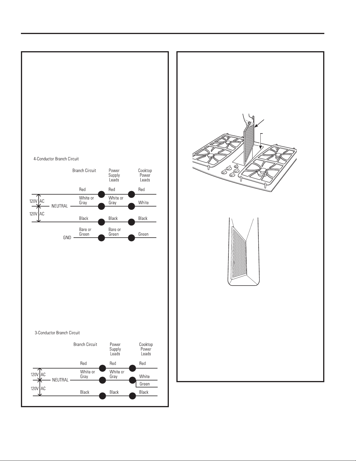
49-2001160 Rev. 0 25
INSTRUCCIONES DE INSTALACIÓN
Instrucciones de Instalación
CÓMO INSTALAR LA ESTUFA (Cont.)
18. CÓMO HACER LAS
CONEXIONES ELÉCTRICAS
(Cont.)
Circuito de ramal de 4 conductores
Cuando conecte la estufa a un circuito de cuatro
conductores o filamentos, conecte los conductores rojos
de la estufa y el suministro eléctrico al conductor rojo del
ramal del circuito; conecte los conectadores negros entre
sí. Conecte el conductor blanco de la estufa al suministro
eléctrico y a los conductores neutros del ramal del
circuito, los que son blancos o grises. Conecte a tierra la
unidad conectando el conductor verde de la estufa a los
conductores pelados o verdes del suministro eléctrico y
GHOUDPDOGHFLUFXLWRFRQGXFWRUHVGHFRQH[LyQDWLHUUD
Conexión de ramal de circuito de tres conductores
• Cuando se encuentre instalando en una construcción
existente construida antes del 1 de enero de 1996, y si
DVtORSHUPLWHQORVFyGLJRVORFDOHV
Conexión de ramal de circuito de 3 conductores
Cuando conecte la estufa a un circuito de 3 conductores,
conecte los conductores rojos de la estufa y el suministro
eléctrico al conductor rojo del ramal del circuito; conecte
los conductores negros entre sí. Conecte los conductores
verdes y blancos de la estufa al suministro eléctrico y a
los conductores neutros del ramal del circuito eléctrico,
que son blancos o grises.
19. CÓMO INSTALAR EL FILTRO
DE FLUJO DOWNDRAFT Y LA
PARRILLA DE VENTILACIÓN
1RRSHUHODYHQWLODFLyQVLQHOILOWURHQVXOXJDU
• Coloque el filtro diagonalmente a través de la
abertura de ventilación.
• Cerciórese de que el filtro descanse, en un
ángulo, en los soportes de la abertura de
ventilación.
• Cuidadosamente coloque la parrilla de ventilación
en la abertura de ventilación de aire descendente
GRZQGUDIW
INSPECCIONE LA OPERACIÓN DE
VENTILACIÓN DE AIRE DESCENDENTE
(DOWNDRAFT)
• Gire el control de velocidad del ventilador de
YHQWLODFLyQDODSRVLFLyQ+,$OWR0('0HGLR
\/2%DMRSDUDFHUFLRUDUVHGHTXHWRGDVODV
velocidades operan correctamente.
Vent Filter
Vent
Chamber
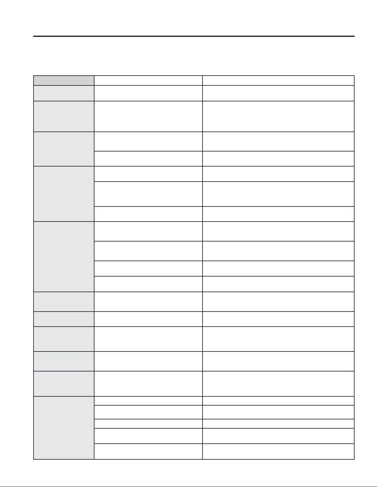
26 49-2001160 Rev. 0
Consejos para la Solución de Problemas... Antes de solicitar el servicio técnico
Problema Causa Posible Qué Hacer
El agua no hierve &XEUDODVDUWpQFRQXQDWDSD$SDJXHHOYHQWLODGRU3RVLFLyQ
OFF) hasta que el agua comience a hervir.
Las unidades de
la superficie no
mantienen un hervor
fuerte o la cocción es
lenta
Se usaron utensilios inadecuados. Los fondos de las ollas deberán ser planos, poseer bastante
peso y ser del mismo diámetro que la unidad de la superficie
seleccionada.
Las unidades de
la superficie no
funcionan de forma
correcta
Es posible que haya un fusible quemado
en su hogar o que se haya desconectado
el disyuntor.
Reemplace el fusible o reinicie el disyuntor.
Los controles del horno fueron
configurados de forma incorrecta.
Asegúrese de que el control correcto esté configurado para la
unidad de la superficie que está usando.
Pequeñas rayas o
marcas sobre el metal
pueden aparecer como
fisuras y abrasiones
sobre la superficie
de vidrio de la cocina
radiante
Uso de métodos incorrectos de limpieza. Lea la sección de Limpieza de la cocina de vidrio.
Se usaron utensilios con partes inferiores
ásperas o partículas ásperas (sal o arena)
entre el utensilio y la superficie de la
cocina.
Asegúrese que las partes inferiores de los utensilios estén
OLPSLDVDQWHVGHVXXVR8VHXWHQVLOLRVFRQSDUWHVLQIHULRUHVOLVDV
Las rayas pequeñas no se pueden eliminar pero serán menos
visibles con el tiempo como resultado de la limpieza.
El utensilio fue deslizado sobre la superficie
de la cocina.
Lea la sección de Limpieza de la superficie de cocción de vidrio.
Áreas de decoloración
o rayas oscuras en la
estufa
Se usaron utensilios inadecuados. Las marcas de cacerolas de aluminio y cobre, como también
depósitos de minerales de agua o comida se pueden eliminar con
la crema de limpieza.
Superficies calientes en un modelo con
una estufa de color pálido.
Esto es normal. La superficie podría parecer decolorada cuando
está caliente. Esto es temporal y desaparecerán conforme el
vidrio se enfría.
Derrames de comida que no se limpiaron
hasta el siguiente uso.
Consulte la sección de Limpieza de la Superficie de Cocción.
Uso de métodos incorrectos de limpieza. 8VHORVSURFHGLPLHQWRVGHOLPSLH]DUHFRPHQGDGRV
Plástico fundido sobre
la superficie
La estufa caliente se puso en contacto con
un instrumento plástico colocado sobre la
estufa caliente.
Ver la sección de Superficie de vidrio – potencial de daño
permanente en la sección de Limpieza de la Superficie de Cocción.
Indentaciones sobre la
estufa
Derrame de una mezcla de azúcar sobre la
estufa.
Llame a un técnico clasificado para reemplazo.
Ciclo de encendido
y apagado frecuente
de las unidades de la
superficie
Se usaron utensilios inadecuados. 8VHVyORXWHQVLOLRVSODQRVSDUDPLQLPL]DUORVFLFORV
La superficie de
cocción se siente
caliente
Se usaron utensilios inadecuados. Es posible que la superficie de cocción de vidrio parezca más
FDOLHQWHGHORKDELWXDO(VWRHVQRUPDO8VHROODVTXHVHDQ
absolutamente planas.
La perilla de control
no gira
Los controles del horno fueron
configurados de forma incorrecta.
&XDQGRODSHULOODVHHQFXHQWUHHQODSRVLFLyQ2II$SDJDGR
se deberá presionar para poder girarla. Cuando la perilla se
encuentre en cualquier otra posición se podrá girar sin se
presionada.
Ventilación
insuficiente
Filtro atascado. Limpie el filtro siguiendo las instrucciones.
Falta de aire en la casa. Abra una ventana levemente para acceder a una fuente de aire
fresco.
Tapa de pared obstruida. Retire el bloqueo de la tapa de pared exterior.
Puerta del regulador de la tapa de pared
atascada.
Controle que la puerta del regulador de la tapa de pared exterior
cuente con un movimiento libre y sin obstrucciones.
La longitud del conducto supera el
máximo equivalente a 100 pies.
Reduzca el número de codos para simplificar el recorrido del
conducto.
¡Ahorre tiempo y dinero! Primero revise los cuadros que aparecen en las siguientes páginas y es posible que no necesite solicitar
reparaciones.
$FFHGDDORVYLGHRVGHD\XGD\SUHJXQWDVIUHFXHQWHV)$4DWUDYpVGHGEAppliances.com/support.
CONSEJOS PARA LA SOLUCIÓN DE PROBLEMAS

49-2001160 Rev. 0 27
Notas
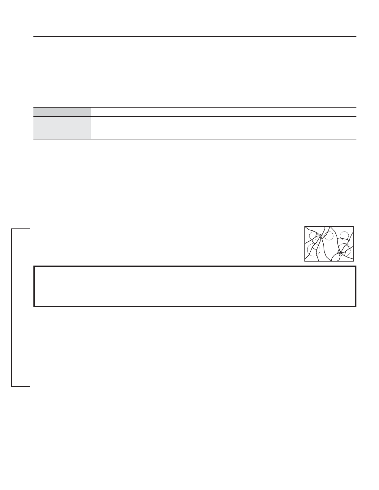
28 49-2001160 Rev. 0
Abroche su recibo aquí. Para acceder al servicio técnico de acuerdo con
la garantía deberá contar con la prueba de la fecha original de compra.
GEAppliances.com
Todo el servicio de garantía es provisto por nuestros Centros de Servicio de Fabricación, o un técnico autorizado de Customer Care®.
Para programar una visita del servicio técnico a través de Internet, visítenos en GEAppliances.com/service, o llame a GE Appliances
al 800.GE.CARES. Cuando llame para solicitar el servicio, tenga los números de serie y modelo disponibles.
Para realizar el servicio técnico de su electrodoméstico, se podrá requerir el uso de datos del puerto de abordaje para su diagnóstico.
Esto da al técnico del servicio de fábrica de GE Appliances la habilidad de diagnosticar de forma rápida cualquier problema con
su electrodoméstico, y de ayudar a GE Appliances a mejorar sus productos al brindarle a GE Appliances la información sobre su
electrodoméstico. Si no desea que los datos de su electrodoméstico sean enviados a GE Appliances, solicitamos que le indique a su
técnico no entregar los datos a GE Appliances en el momento del servicio.
Qué no cubrirá GE Appliances:
Ŷ 9LDMHVGHOWpFQLFRGHOVHUYLFLRDVXKRJDUSDUDHQVHxDUOH
sobre cómo usar el producto.
Ŷ ,QVWDODFLyQHQWUHJDRPDQWHQLPLHQWRLQDGHFXDGRV
Ŷ )DOODVGHOSURGXFWRHQFDVRGHDEXVRPDOXVRPRGLILFDFLyQ
o uso para propósitos diferentes al original o uso comercial.
Ŷ 'DxRVVREUHODVXSHUILFLHGHFRFFLyQGHYLGULRTXHVHDQ
ocasionados por el uso de limpiadores que no sean las
cremas de limpieza o almohadillas recomendadas.
Ŷ 'DxRVVREUHODVXSHUILFLHGHFRFFLyQGHYLGULRRFDVLRQDGRV
por derrames habituales de materiales azucarados o
plásticos derretidos que no se limpien de acuerdo con las
instrucciones que figuran en el Manual del Propietario.
Ŷ 5HHPSOD]RGHIXVLEOHVGHODFDVDRUHLQLFLRGHGLV\XQWRUHV
Ŷ 'DxRVRFDVLRQDGRVVREUHHOSURGXFWRSRUDFFLGHQWH
incendio, inundaciones o catástrofes naturales.
Ŷ 'DxRVLQFLGHQWDOHVRFRQVHFXHQWHVFDXVDGRVSRUSRVLEOHV
defectos sobre este producto.
Ŷ 'DxRFDXVDGRGHVSXpVGHODHQWUHJD
Ŷ 3URGXFWRQRDFFHVLEOHSDUDEULQGDUHOVHUYLFLRUHTXHULGR
Ŷ 6ROLFLWHHOVHUYLFLRWpFQLFRSDUDUHSDUDURUHHPSOD]DUODV
lámparas, excepto las lámparas LED.
Ŷ $SDUWLUGHHQHURGDxRVHVWpWLFRVVREUHODSODFDGH
cocción de vidrio tales como, pero sin limitarse a, astillas,
rayones, o residuos horneados que no se hayan reportado
dentro de los 90 días desde el momento de la instalación.
Ŷ $SDUWLUGHHQHURGDxRVVREUHODSODFDGHFRFFLyQ
de vidrio debido a impactos o uso
inadecuado. Vea el ejemplo.
GARANTÍA LIMITADA
Limitada Garantía
EXCLUSIÓN DE GARANTÍAS IMPLÍCITAS
Su única y exclusiva alternativa es la reparación del producto, como se indica en la Garantía Limitada. Las
garantías implícitas, incluyendo garantías implícitas de comerciabilidad o conveniencia sobre un propósito
particular, se limitan a un año o al período más corto permitido por la ley.
Por el Período de GE Appliances reemplazará
Un Año
Desde la fecha de la
compra original
Cualquier parte de la estufa que falle debido a un defecto en los materiales o la fabricación. Durante
esta garantía limitada de un año, GE Appliances también proveerá, sin costo, todo el trabajo y el
servicio en el hogar para reemplazar la parte que presente defectos.
Esta garantía limitada se extiende al comprador original y a cualquier propietario posterior de los productos
FRPSUDGRVSDUDXVRGRPpVWLFRGHQWURGH((886LHOSURGXFWRHVWiHQXQiUHDGRQGHQRVHHQFXHQWUDGLVSRQLEOH
un Proveedor Autorizado del Servicio Técnico de GE Appliances, usted será responsable por el costo de un viaje o se
podrá requerir que traiga el producto a una ubicación del Servicio Técnico de GE Appliances autorizado para recibir el
servicio. En Alaska, la garantía limitada excluye el costo de envío o visitas de servicio a su domicilio. Algunos estados
no permiten la exclusión o limitación de daños fortuitos o consecuentes. Esta garantía limitada le otorga derechos
legales específicos, y usted también podría tener otros derechos que varían de estado a estado. Para conocer cuáles
son sus derechos legales, consulte a la oficina de asuntos del consumidor local o estatal o al Fiscal de su estado.
Garante: GE Appliances, a Haier company
Louisville, KY 40225
Garante en Canadá: MC Commercial
%XUOLQJWRQ21/5%
Garantías Extendidas: Adquiera una garantía extendida de GE Appliances y conozca los descuentos especiales que
están disponibles mientras su garantía aún está vigente. Puede acceder a la misma a través de Internet en cualquier
momento en
GEAppliances.com/extended-warranty
o llamando al 800.626.2224 durante el horario comercial. Los Servicios para los GE Appliances aún estarán
disponibles cuando su garantía caduque.

49-2001160 Rev. 0 29
ACCESORIOS
¿Busca Algo Más?
¡GE Appliances ofrece una variedad de accesorios para
mejorar sus experiencias de cocción y mantenimiento!
Para acceder a números telefónicos e información de sitios
Web, consulte la página de Soporte para el Consumidor.
(VWRV\RWURVSURGXFWRVHVWiQGLVSRQLEOHV
Accesorios
Accesorios
Kit de Instalación Alternativa
Suministros de Limpieza
Limpiadores de Acero Inoxidable CitriShine
TM
Tela para Pulir Acero Inoxidable
Removedor de Grasa Quemada
Limpiador de Electrodomésticos de Acero Inoxidable
Almohadillas de Limpieza Antirayaduras para Superficies de Cocción de Cerámica
Limpiador para Superficies de Cocción de Vitrocerámico
Kit de Limpieza
Kit de Eliminación de Rayaduras sobre Acero Inoxidable

30 49-2001160 Rev. 0
,PSUHVRHQ(VWDGRV8QLGRV
Soporte para el Consumidor
SOPORTE PARA EL CONSUMIDOR
Sitio Web de GE Appliances
¿Desea realizar una consulta o necesita ayuda con su electrodoméstico? ¡Intente a través del Sitio Web de GE Appliances las
KRUDVGHOGtDFXDOTXLHUGtDGHODxR8VWHGWDPELpQSXHGHFRPSUDUPiVHOHFWURGRPpVWLFRVPDUDYLOORVRVGH*($SSOLDQFHV\
aprovechar todos nuestros servicios de soporte a través de Internet, diseñados para su conveniencia.
(Q((88GEAppliances.com
Registre su Electrodoméstico
£5HJLVWUHVXHOHFWURGRPpVWLFRQXHYRDWUDYpVGH,QWHUQHWVHJ~QVXFRQYHQLHQFLD8QUHJLVWURSXQWXDOGHVXSURGXFWRSHUPLWLUi
una mejor comunicación y un servicio más puntual de acuerdo con los términos de su garantía, en caso de surgir la necesidad.
También puede enviar una carta en la tarjeta de inscripción preimpresa que se incluye con el material embalado.
(Q((88GEAppliances.com/register
Servicio Programado
El servicio de reparación de expertos de GE Appliances está a sólo un paso de su puerta. Conéctese a través de Internet y programe
VXVHUYLFLRDVXFRQYHQLHQFLDFXDOTXLHUGtDGHODxR(Q((88GEAppliances.com/service
o comuníquese al 800.432.2737 durante el horario de atención comercial.
Garantías Extendidas
Adquiera una garantía extendida de GE Appliances y conozca los descuentos especiales que están disponibles mientras su
garantía aún está vigente. La puede adquirir en cualquier momento a través de Internet. Los servicios de GE Appliances aún
estarán allí cuando su garantía caduque.
(Q((88GEAppliances.com/extended-warranty
o comuníquese al 800.626.2224 durante el horario de atención comercial.
Conectividad Remota
3DUDVROLFLWDUDVLVWHQFLDSDUDODFRQHFWLYLGDGGHUHGLQDOiPEULFDSDUDPRGHORVFRQDFFHVRUHPRWR
YLVLWHQXHVWURVLWLRZHEHQGEAppliances.com/connect RFRPXQtTXHVHDOHQ((88
Piezas y Accesorios
Aquellos individuos calificados para realizar el servicio técnico de sus propios electrodomésticos podrán solicitar el envío de
SLH]DVRDFFHVRULRVGLUHFWDPHQWHDVXVKRJDUHVVHDFHSWDQODVWDUMHWDV9,6$0DVWHU&DUG\'LVFRYHU2UGHQHKR\DWUDYpVGH
,QWHUQHWGXUDQWHODVKRUDVWRGRVORVGtDV(Q((88GEApplianceparts.com o de forma telefónica al 877.959.8688 durante
el horario de atención comercial.
Las instrucciones que figuran en este manual cubren los procedimientos que serán realizados por cualquier usuario.
Otros servicios técnicos generalmente deben ser derivados a personal calificado del servicio. Se deberá tener cuidado,
ya que una reparación indebida podrá hacer que el funcionamiento no sea seguro.
Contáctenos
Si no se encuentra satisfecho con el servicio que recibió de GE Appliances, comuníquese con nosotros a través de nuestro sitio
:HEFRQWRGRVORVGHWDOOHVLQFOX\HQGRVXQ~PHURWHOHIyQLFRRHVFULEDD
(Q((88*HQHUDO0DQDJHU&XVWRPHU5HODWLRQV_*($SSOLDQFHV$SSOLDQFH3DUN_/RXLVYLOOH.<
GEAppliances.com/contact