Loading ...
Loading ...
Loading ...
Part Number 550-142-303/1120
11
EG
/
PEG sEriEs 6
•
EGH sEriEs 5 Gas-firEd boilErs — boilEr manual
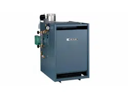
Installation of flue collector hood
(Factory installed on PEG boilers)
Set flue collector hood on boiler as shown in Figure 6b. Use boiler
cement furnished to provide gas-tight seal.
Failure to maintain gas-tight seal can cause flue gas
spillage and carbon monoxide emissions, resulting
in severe personal injury or death.
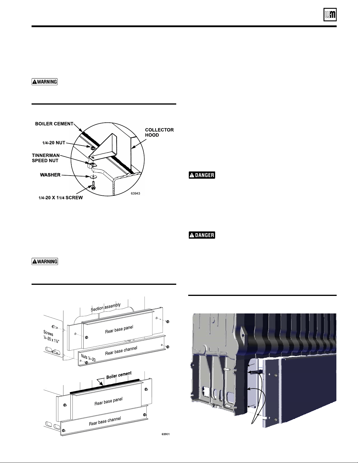
Installation of rear base panels
(Factory installed on PEG boilers)
For EG-30 through 75, see Figure 7a, for EGH-85 through
-125, see Figure 7b. Fasten rear base panel (7 5/16 inch high -
EG/PEG - 2 pieces) and rear base (11 17/32 inch high - EGH
- 1 piece) channel to section assembly. Seal with boiler cement
along top of insulation panels.
Failure to maintain gas-tight seal can cause flue
gas spillage and carbon monoxide emissions,
resulting in severe personal injury or death.
Figure 7a EG/PEG - Rear base panel and base channel
Prepare the boiler (continued)
Installation of side refractory -EGH only
1. See Figure 7b & 7d. Hardware for drawer assembly must be
installed (Figure 10, page 12), before sliding refractory in place.
2. Apply silicone to the inside surface of the cast iron end
section leg.
3. Slide refractory (2 pieces left & right side) into place.
4. Install four (4) refractory clips (See Figure 7b & 7d) to hold
refractory in place.
Installation of drawer assembly, front
base panels – EG/EGH
(Factory installed on PEG boilers)
1. See Figure 7c, page 12. Fasten front base panel (6 Z\, inch high)
and rear base channel to section assembly. Seal with boiler
cement along top of insulation panels.
2. The burner drawer assembly consists of the burner drawer,
main burners, gas manifold, pilot burner, etc.
3. Check for proper orifice sizing from Table 5, page 13.
Proper orifices must be used. Failure to do so will
cause severe personal injury, death or substantial
property damage.
4. Place burners in the drawer assembly as shown in Figures 8
and 9, page 12.
5. Slide the drawer assembly under the front base panel and at-
tach to the section assembly as shown in Figure 10, page 12.
6. Level and straighten burners.
Burners must be properly seated in slots in back
burner support with openings facing up. Gas
orifices must inject down center of burner. Failure
to properly seat burners will result in severe personal
injury, death or substantial property damage.
7. EG 30 – EG-75 only: Install rollout thermal fuse element with
wire terminals facing up on front access panel as shown in
Figure 11, page 13. Wire per the appropriate Control Supple-
ment.
Figure 6b Flue collector hood
Figure 7b EGH - Rear base panel & refractory and
refractory clip
Note! Silicone to be applied to inside of leg of cast surface.
Loading ...
Loading ...
Loading ...