Loading ...
Loading ...
Loading ...
17
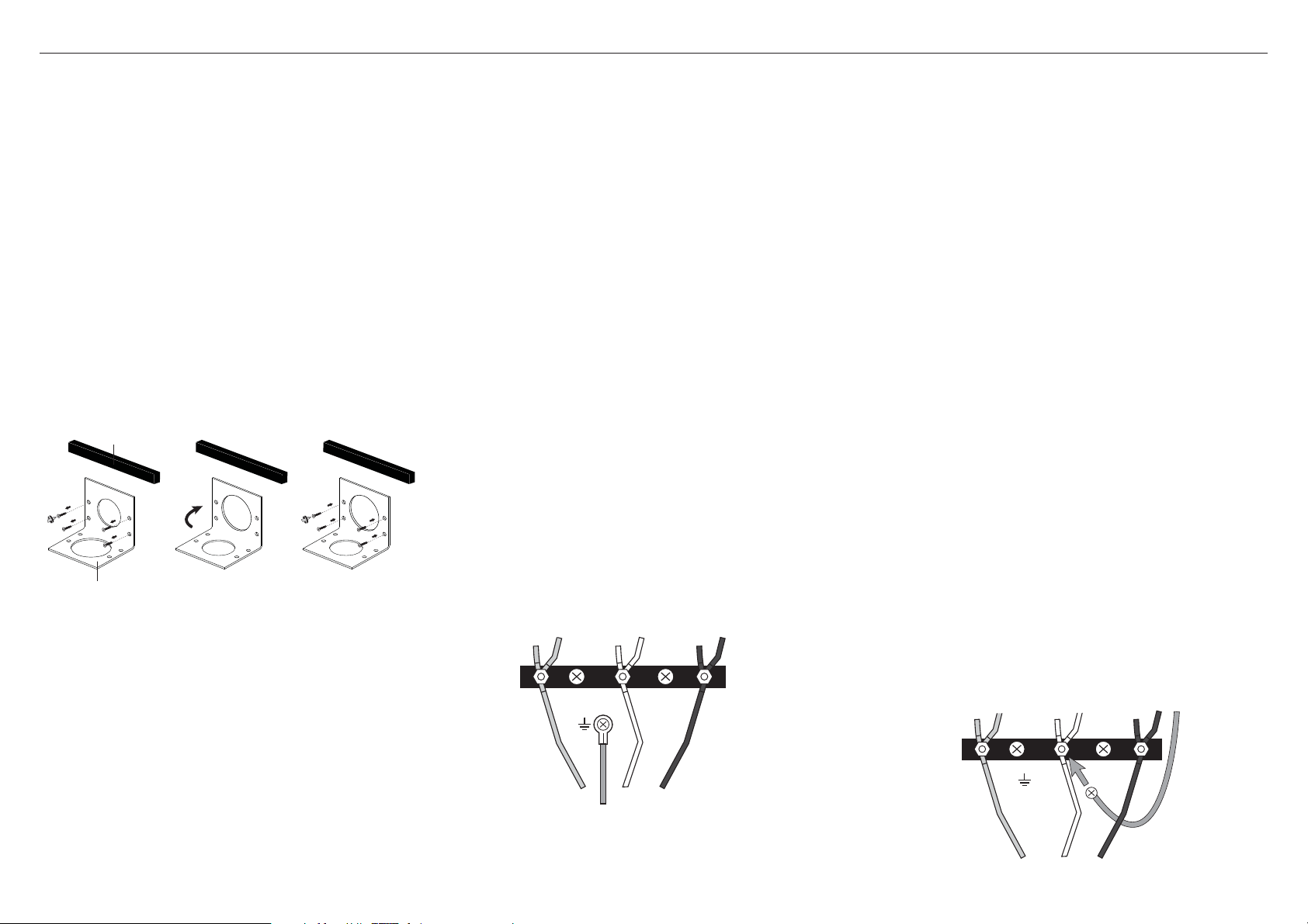
GREEN GROUND
Reconnect
here
RED WIRE
WHITE WIRE
(NEUTRAL)
BLACK WIRE
!4ELECTRICAL CONNECTION
RDV2 MODELS
Terminal Block
Strain relief bracket
●
Dual Fuel models must be connected to the power supply utilizing one of the following methods. For all methods of connection, the length of the cord or conduit/wiring must allow the unit
to be slid completely out of the cabinet without having to unplug or disconnect the unit from the power supply. Recommended minimum free length of cord or conduit is 4ft (1.2m). Electrical
installations and grounding must be in accordance with all local codes and ordinances, and/or the National Electric Code, as applicable.
PERMANENT CONNECTION (HARD WIRING)
●
Units may be hard wired to the power supply. The
installer must provide approved flexible steel conduit,
maximum 6ft (1.8m) long. Locate the terminal block on
the rear of the unit and remove access cover.
●
The strain relief bracket orientation must be switched
in order to accommodate for a permanent wiring
connection. This is done by the following:
1 Remove the 4 screws on the bracket.
2 Re-secure bracket with the four screws so that the
1 1/8” (29mm) smaller opening is orientated over the
opening of the back panel.
●
The conduit must be installed to the terminal block using
an approved conduit connector. The free end of the
conduit must be connected to a junction box provided in
the electrical supply zone.
●
Mount a strain relief (not provided) into the 1 1/8”
(29mm) diameter hole located below the terminal block.
Wiring for the unit is to be brought into the terminal
block through the conduit and through the strain relief.
The ends of the wiring must have 1/4” faston closed loop
lugs attached. Make suitable connections to the terminal
block provided.
●
See over for 4-wire and 3-wire connection
●
Installer — Show the owner the location of the circuit
breaker. Mark it for easy reference.
4-CONDUCTOR CORD
●
NORMALLY, A UNIT MUST BE CONNECTED TO THE
POWER SUPPLY WITH A 3-POLE, 4-CONDUCTOR CORD
KIT RATED 125/250 VOLTS, 50 AMPERES, AND MARKED
FOR USE WITH RANGES.
●
The cord kit must be attached to the range terminal block
with a strain relief which will fit a 1-3/8” (35mm) diameter
hole. If not already equipped, the cord must also have 1/4”
(6mm) faston closed-loop lugs attached to the free ends
of the individual conductors, preferably soldered in place.
1 Remove upper nuts only from the terminal block studs. Do
not remove lower nuts which secure range internal wiring
leads.
2 Mount strain relief (not provided with range) into the
1-1/2” (38mm) diameter hole in the bracket located below
the terminal block. Route wires up through strain relief.
4-Wire Connection
3 Secure the Neutral (white) power lead, to the center stud
(silver colored) of the terminal block with nut.
4 Secure the L1 (black) and L2 (red) power leads to the
outside terminal studs (brass colored) with nuts.
5 Secure the Ground (green) power lead to the back of the
range with the screw located beneath the terminal block.
6 Tighten all connections securely.
7 Reinstall the Terminal Block Cover.
3-CONDUCTOR CORD
●
WHERE LOCAL CODES AND ORDINANCES PERMIT
GROUNDING THROUGH NEUTRAL, AND CONVERSION
OF SUPPLY TO 4 WIRE IS IMPRACTICAL, UNIT MAY BE
CONNECTED TO THE POWER SUPPLY WITH A 3-POLE,
3-CONDUCTOR CORD KIT RATED 125/250 VOLTS, 50
AMPERES, AND MARKED FOR USE WITH RANGES.
The cord kit must be attached to the range back panel
with a strain relief which will fit a 1-1/2” (38mm) diameter
hole. If not already equipped, the cord must also have
1/4” (6mm) faston closed-loop lugs attached to the free
ends of the individual conductors.
1 Remove upper nuts only from the terminal block studs.
Do not remove nuts which secure range internal wiring
leads.
2 Mount strain relief (not provided with range) into the
1-1/2” (38mm) diameter hole in the bracket located below
the terminal block. Route wires up through strain relief.
3-Wire Lead Connection
3 Secure the L1 (black) and L2 (red) power leads to the
outside corresponding terminal block studs (brass
colored).
4 Secure the Neutral (white), grounded wire of the supply
circuit and reconnect one end of the mounted looped
Ground wire, located beneath terminal block, to the
center stud (silver colored) of the terminal block with nut.
5 Leave the other end of the Ground wire screwed into the
back of the range.
6 Tighten nuts securely.
7 Reinstall the Terminal Block Cover.
RED WIRE
GREEN GROUND
WHITE WIRE
(NEUTRAL)
BLACK WIRE
1 2 3
Loading ...
Loading ...
Loading ...