Loading ...
Loading ...
Loading ...
16
The electrical supply must be a correctly polarized 120 VAC, 60 Hz, single phase circuit
suitable for the maximum current draw of the model, as detailed in the table below.
Verify your model’s current draw by checking the rating label on the back of the range.
MODEL
MAX.
CURRENT DRAW
CIRCUIT FREQUENCY
RGV2-305 5 A 15 A 60 Hz
RGV2-364GD 8 A 15 A 60 Hz
RGV2-304 5 A 15 A 60 Hz
RGV2-366 5 A 15 A 60 Hz
RGV2-488 9 A 15 A 60 Hz
RGV2-485GD 15 A 15 A 60 Hz
RGV2-486GD 12 A 15 A 60 Hz
RGV2-486GL 12 A 15 A 60 Hz
Required grounding method – RGV2 MODELS
●
This appliance is factory equipped with a power supply cord with a three-prong
grounding plug (with polarized parallel blades). It must be plugged into a mating
grounding-type receptacle, connected to a correctly polarized 120 VAC. If the circuit
does not have a grounding type receptacle, it is the responsibility and obligation of the
installer to have the existing receptacle changed to a properly grounded and polarized
receptacle in accordance with all applicable local codes and ordinances by a qualified
electrician. In the absence of local codes and ordinances, the receptacle replacement
shall be in accordance with the National Electrical Code.
●
IMPORTANT!
The third prong should not, under ANY circumstances, be cut or removed.
Required grounding method – RGV2 MODELS
●
This appliance is factory equipped with a power supply cord with a NEMA 14-50 four-
prong grounding plug. It must be plugged into a mating grounding, type receptacle,
connected to a correctly polarized 120/240 VAC. If the circuit does not have a
grounding type receptacle, it is the responsibility and obligation of the installer to
have the existing receptacle changed to a properly grounded and polarized receptacle
in accordance with all applicable local code and ordinances by a qualified electrician.
In the absence of local codes and ordinances, the receptacle replacement shall be in
accordance with the National Electrical Code.
●
IMPORTANT!
The fourth prong (round grounding pin) should not, under any circumstances, be cut
or removed.
●
A neutral supply wire must be provided from the power source (breaker panel) because
critical range components, including the surface burner spark reignition module, require
120/240 VAC to operate safely and properly.
●
If the correct power supply circuit is not provided, it is the responsibility and obligation
of the installer and user to have proper power supply connected. This must be
accomplished in accordance with all applicable local codes and ordinances by a qualified
electrician. It is the responsibility of the installer to ensure compliance of local codes.
In the absence of local codes and ordinances, the power supply connection shall be in
accordance with the National Electric Code.
●
Observe all governing codes and ordinances when grounding. In the absence of these
codes or ordinances observe National Electrical Code ANSI/NFPA No. 70 current issue.
See the following information in this section for grounding method..
●
The ranges are to be connected to a 240/208 VAC power supply.
IMPORTANT!
An improper 120/ 240 VAC power supply will cause malfunction, damage to this
appliance, and possibly create a condition of shock hazard.
Improper connection of aluminum house wiring can result in a fire or shock hazard.
Use only connectors designed and certified for connecting to aluminum wire.
MODEL
MAX.
CURRENT DRAW
CIRCUIT FREQUENCY
RDV2-305 18 A 30 A 60 Hz
RDV2-304 21 A 30 A 60 Hz
RDV2-364GD 21 A 30 A 60 Hz
RDV2-366 18 A 30 A 60 Hz
RDV2-488 33 A 50 A 60 Hz
RDV2-485GD 40 A 50 A 60 Hz
RDV2-486GD 36 A 50 A 60 Hz
RDV2-486GL 36 A 50 A 60 Hz
!4ELECTRICAL CONNECTION
ALL MODELS
RDV2 MODELS
IMPORTANT!
●
This range must be connected to the mains
power supply only by a suitably qualified person.
●
This range must be earthed.
●
Always disconnect electric supply cord from the
wall outlet or service disconnect before servicing
this appliance.
●
Observe all governing codes and ordinances
when grounding, in absence of which, observe
National Electrical Code ANSI / NFPA No. 70.
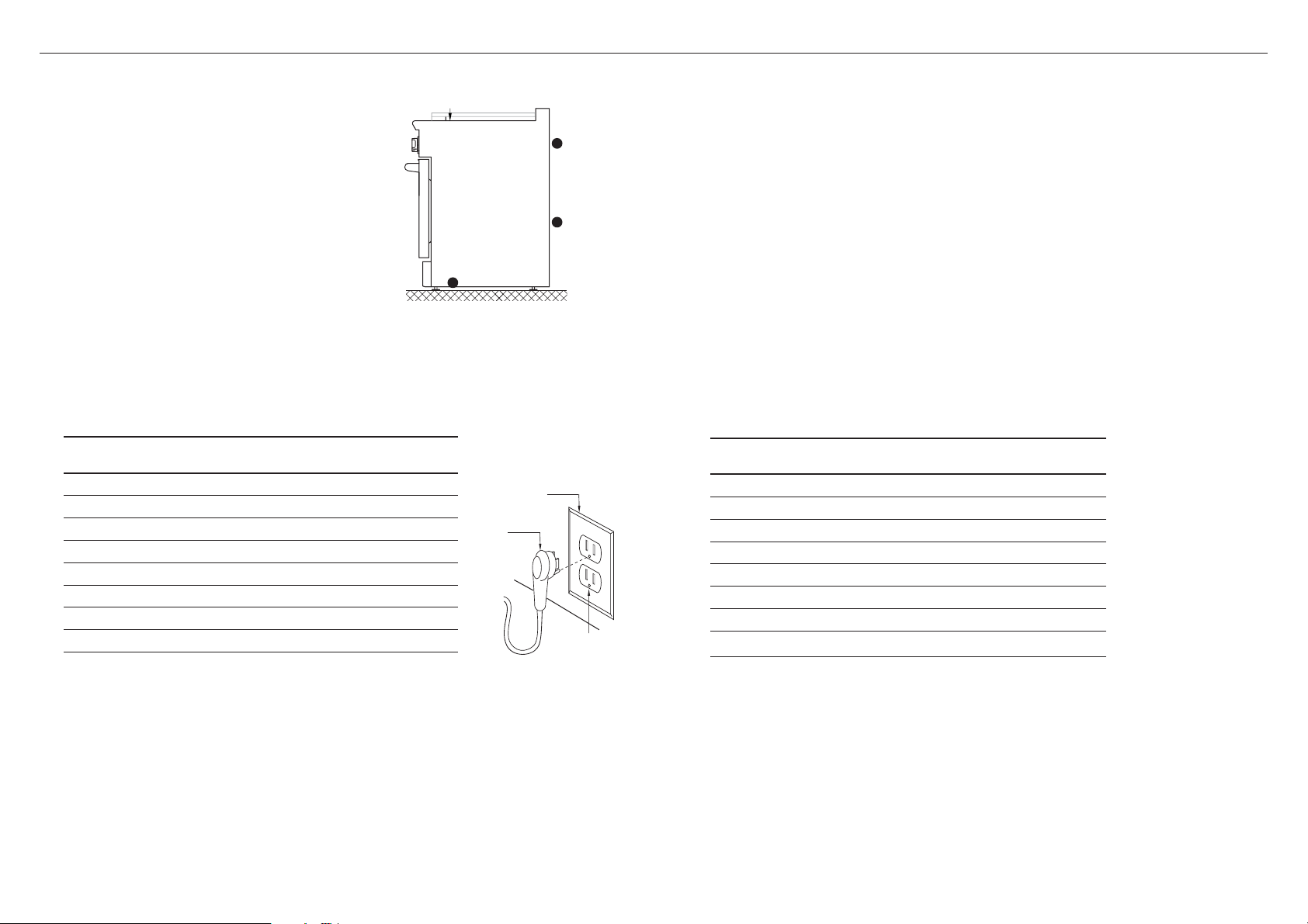
The rating
label is located
on the back of
the range
A wiring
diagram label
is attached to
the back of
the range
Wiring diagrams
are also in the
service summary,
attached to the
inside of the kick
panel
RGV2 MODELS
Receptacle Box
Cover Plate
Three Prong
Receptacle
Three
Prong
Plug
Loading ...
Loading ...
Loading ...