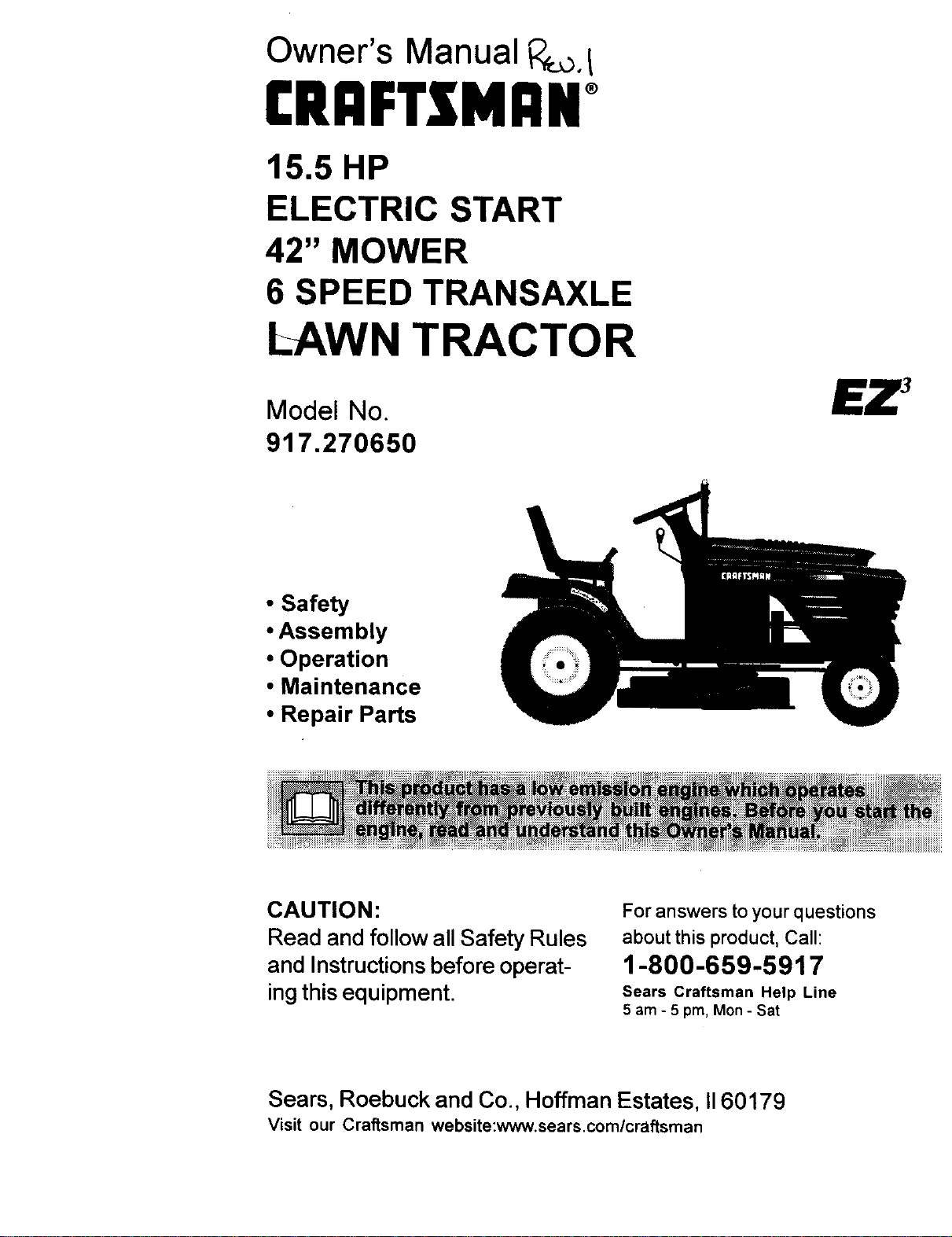
Owner's Manual i::__o.I
CRRFTSMRNo
15.5 HP
ELECTRIC START
42" MOWER
6 SPEED TRANSAXLE
LAWN TRACTOR
Model No.
917.270650
• Safety
• Assembly
• Operation
• Maintenance
• Repair Parts
CAUTION:
Read and follow all Safety Rules
and Instructionsbefore operat-
ing this equipment.
For answers to your questions
about this product, Call:
1-800-659-5917
Sears Craftsman Help Line
5 am - 5 pro, Mon - Sat
Sears, Roebuck and Co., Hoffman Estates, II60179
Visit our Craftsman website:www.sears.com/craftsman
Warranty...............................................2
SafetyRules.........................................2
ProductSpecifications..........................5
Assembly..............................................8
Operation............................................11
MaintenanceSchedule......................17
Serviceand Adjustments .................... 21
Storage ............................................... 27
Troubleshooting ................................. 28
Repair Parts ........................................ 32
Parts Ordering ..................... Back Cover
LIMITED TWO YEAR WARRANTY ON CRAFTSMAN RIDING EQUIPMENT
For two (2) years from the date of purchase, if this Craftsman Riding Equipment is
maintained, lubricated and tuned up according to the instructions in the owner's
manual, Sears will repair or replace, free of charge, any parts found to be defective in
material or workmanship.
This Warranty does not cover:
• Expendable items which become worn during normal use, such as blades, spark
plugs, air cleaners, belts, etc.
• Tire replacement or repair caused by punctures from outside objects, such as nails,
thorns, stumps, or glass.
• Repairs necessary because of operator abuse, negligence, improper storage or
accident or the failure to maintain the equipment according to the instructions
contained in the owner's manual.
• Riding equipment used for commercial or rental purposes.
LIMITED 90 DAY WARRANTY ON BAI-rERY
For ninety (90) days from date of purchase, if any battery included with this riding
equipment proves defective in material or workmanship and our testing determines the
battery will not hold a charge, Sears will replace the battery at no charge. In-home
warranty service on your Craftsman riding equipment is available at no charge for 30
days from the date of purchase. Please contact your nearest service center. After 30
days from the date of purchase, warranty service is available by taking your Craftsman
riding equipment to your nearest Sears Service Center. (In-home warranty service will
still be available after 30 days from the date of purchase but a standard trip charge will
apply). This warranty applies only while this product is in the United States. This
Warranty gives you specific legal rights, and you may also have other rights which may
vary from state to state.
Sears, Roebuck and Co., D/817 WA, Hoffman Estates, IL 60179
IMPORTANT: This cutting machine is
capable of amputating hands and feet
and throwing objects. Failure to observe
the following safety instructions could
result in serious injury or death.
GENERAL OPERATION
• Read, understand, and follow all
instructions in the manual and on the
machine before starting.
• Only allow responsible adults, who are
familiar with the instructions, to
operate the machine.
• Clear the area of objects such as
rocks, toys, wire, etc., which could be
picked up and thrown by the blade.
2
• Be sure the area is clear of other
people before mowing. Stop machine
if anyone enters the area.
• Never carry passengers.
• Do not mow in reverse unless abso-
lutely necessary. Always look down
and behind before and while backing.
• Be aware of the mower discharge
direction and do not point it at anyone.
Do not operate the mower without
either the entire grass catcher or the
guard in place.
• Slow down before turning.
• Never leave a running machine
unattended. Always turn off blades, set
parking brake, stop engine, and
remove keys before dismounting.
• Turn off blades when not mowing.
• Stop engine before removing grass
catcher or unclogging chute.
• Mow only in daylight or good artificial
light.
• Do not operate the machine while
under the influence of alcohol or
drugs.
• Watch for traffic when operating near
or crossing roadways.
• Use extra care when loading or
unloading the machine into a trailer or
truck.
• Data indicates that operators, age 60
years and above, are involved in a
large percentage of riding mower-
related injuries. These operators
should evaluate their ability to operate
the riding mower safely enough to
protect themselves and others from
serious injury.
SLOPE OPERATION
Slopes are a major factor related to loss-
of-control and tipover accidents, which
can result in severe injury or death. All
slopes require extra caution. If you
cannot back up the slope or if you feel
uneasy on it, do not mow it.
DO:
Mow up and down slopes, not across.
Remove obstacles such as rocks, tree
limbs, etc.
• Watch for holes, ruts, or bumps.
Uneven terrain could overturn the
machine. Tall grass can hide ob-
stacles.
• Use slow speed. Choose a low gear
so that you will not have to stop or shift
while on the slope.
• Follow the manufacturer's recommen-
dations for wheel weights or counter-
weights to improve stability.
• Use extra care with grass catchers or
other attachments. These can change
the stability of the machine.
• Keep all movement on the slopes slow
and gradual. Do not make sudden
changes in speed or direction.
• Avoid starting or stopping on a slope. If
tires lose traction, disengage the
blades and proceed slowly straight
down the slope.
3
DO NOT:
• Do notturn on slopes unless neces-
sary, and then, turn slowly and
gradually downhill, if possible.
• Do not mow near drop-offs, ditches, or
embankments. The mower could
suddenly turn over if a wheel is over
the edge of a cliff or ditch, or if an edge
caves in.
• Do not mow on wet grass. Reduced
traction could cause sliding.
• Do nottry to stabilize the machine by
putting your foot on the ground.
• Do not use grass catcher on steep
slopes.
CHILDREN
Tragic accidents can occur if the operator
is not alert to the presence of children.
Children are often attracted to the
machine and the mowing activity. Never
assume that children will remain where
you last saw them.
• Keep children out of the mowing area
and under the watchful care of another
responsible adult.
• Be alert and turn machine off if"
children enter the area.
• Before and when backing, look behind
and down for small children.
• Never carry children. They may fall off
and be seriously injured or interfere
with safe machine operation.
• Never allow children to operate the
machine.
• Use extra care when approaching
blind corners, shrubs, trees, or other
objects that may obscure vision.
SERVICE
• Use extra care in handling gasoline
and other fuels. They are flammable
and vapors are explosive.
Use only an approved container.
Never remove gas cap or add fuel
with the engine running. Allow en-
gine to cool before refueling. Do
not smoke.
Never refuel the machine indoors.
Never store the machine or fuel
container inside where there is an
open flame, such as a water heat-
er.
• Never run a machine inside a closed
area.
• Keep nuts and bolts, especially blade
attachment bolts, tight and keep
equipment in good condition.
• Never tamper with safety devices.
Check their proper operation regularly.
• Keep machine free of grass, leaves, or
other debris build-up. Clean oil or fuel
spillage. Allow machine to cool before
storing.
• Stop and inspect the equipment if you
strike an object. Repair, if necessary,
before restarting.
• Never make adjustments or repairs
with the engine running.
• Grass catcher components are subject
to wear, damage, and deterioration,
which could expose moving parts or
allow objects to be thrown. Frequently
check components and replace with
manufacturer's recommended parts,
when necessary.
• Mower blades are sharp and can cut.
Wrap the blade(s) or wear gloves, and
use extra caution when servicing
them.
• Check brake operation frequently.
Adjust and service as required.
• Be sure the area is clear of other
people before mowing. Stop machine
if anyone enters the area.
• Never carry passengers.
• Do not mow in reverse unless abso-
lutely necessary. Always look down
and behind before and while backing.
• Never carry children. They may fall off
and be seriously injured or interfere
with safe machine operation.
• Keep children out of the mowing area
and under the watchful care of another
responsible adult.
• Be alert and turn machine off if
children enter the area.
• Before and when backing, look behind
and down for small children.
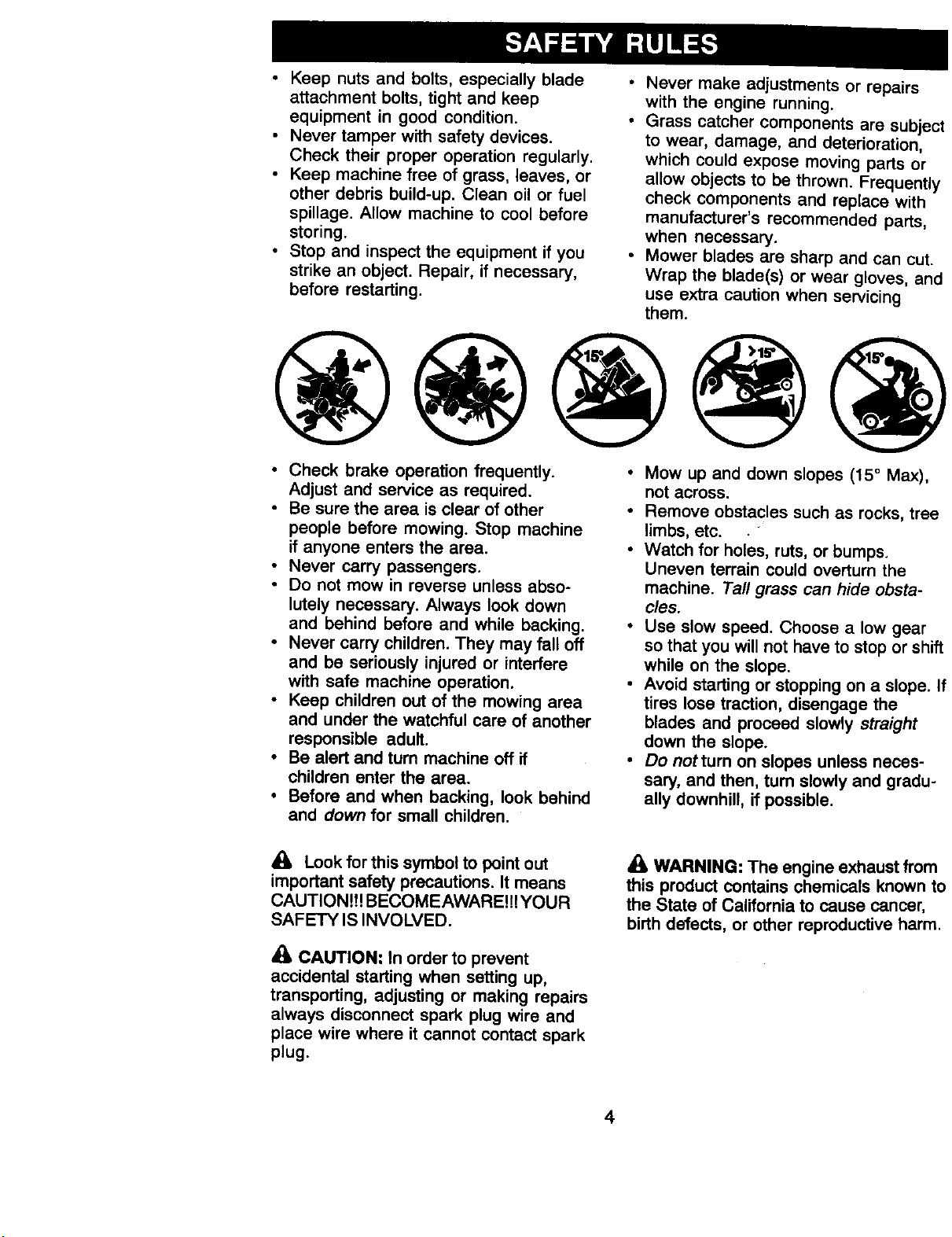
• Mow up and down slopes (15 ° Max),
not across.
• Remove obstacles such as rocks, tree
limbs, etc.
• Watch for holes, ruts, or bumps.
Uneven terrain could overturn the
machine. Tall grass can hide obsta-
cles.
• Use slow speed. Choose a low gear
so that you will not have to stop or shift
while on the slope.
• Avoid starting or stopping on a slope. If
tires lose traction, disengage the
blades and proceed slowly straight
down the slope.
• Do notturn on slopes unless neces-
sary, and then, turn slowly and gradu-
ally downhill, if possible.
_i= Look for this symbol to point out
important safety precautions. It means
CAUTION!!! BECOMEAWARE!!!YOUR
SAFETY IS INVOLVED.
• 1=CAUTION: In order to prevent
accidental starting when setting up,
transporting, adjusting or making repairs
always disconnect spark plug wire and
place wire where it cannot contact spark
plug.
_i WARNING: The engine exhaust from
this product contains chemicals known to
the State of California to cause cancer,
birth defects, or other reproductive harm.
4
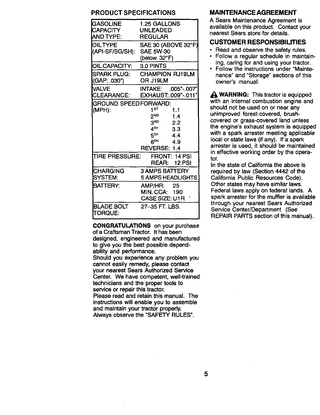
PRODUCT SPECIFICATIONS
GASOLINE
CAPACITY
AND TYPE:
OILTYPE
t_PI-SF/SG/SH):
1.25 GALLONS
UNLEADED
REGULAR
SAE 30 (ABOVE 32°F
SAE 5W-30
(below 32°F)
3.0 PINTS
CHAMPION RJ19LM
OR J19LM
INTAKE: .005"-.007"
EXHAUST: .009"-.011"
::)IL CAPACITY:
SPARK PLUG:
GAP: .030")
_,ALVE
_,LEARANCE:
_ROUND SPEED FORWARD:
CMPH): I s'r 1,1
2N° 1,4
3 R° 2,2
4TM 3.3
5TM 4.4
6TM 4.9
REVERSE: 1.4
TIRE PRESSURE: FRONT: 14 PSI
REAR: 12 PSI
CHARGING 3 AMPS BATTERY
SYSTEM: 5 AMPS HEADLIGHTS
BAI-FERY: AMP/HR: 25
MIN. CCA: 190
CASE SIZE: U1R •
BLADE BOLT 27-35 FT. LBS.
TORQUE:
CONGRATULATIONS on your purchase
of a Craftsman Tractor. It has been
designed, engineered and manufactured
to give you the best possible depend-
ability and performance.
Should you experience any problem you
cannot easily remedy, please contact
your nearest Sears Authorized Service
Center. We have competent, well-trained
technicians and the proper tools to
service or repair this tractor.
Please read and retain this manual. The
instructionswill enable you to assemble
and maintain your tractor properly.
Always observe the "SAFETY RULES".
MAINTENANCEAGREEMENT
A Sears Maintenance Agreement is
available on this product. Contact your
nearest Sears store for details.
CUSTOMER RESPONSIBILITIES
• Read and observe the safety rules.
• Follow a regular schedule in maintain-
ing, caring for and using your tractor.
• Follow the instructions under "Mainte-
nance" and "Storage" sections of this
owner's manual.
WARNING: This tractor is equipped
with an internal combustion engine and
should not be used on or near any
unimproved forest-covered, brush-
covered or grass-covered land unless
the engine's exhaust system is equipped
with a spark arrester meeting applicable
local or state laws (if any). If a spark
arrester is used, it should be maintained
in effective working order by the opera-
tor.
In the state of California the above is
required by law (Section 4442 of the
California Public Resources Code).
Other states may have similar laws.
Federal laws apply on federal lands. A
spark arrester for the muffler is available
through your nearest Sears Authorized
Service Center/Department (See
REPAIR PARTS section of this manual).
5
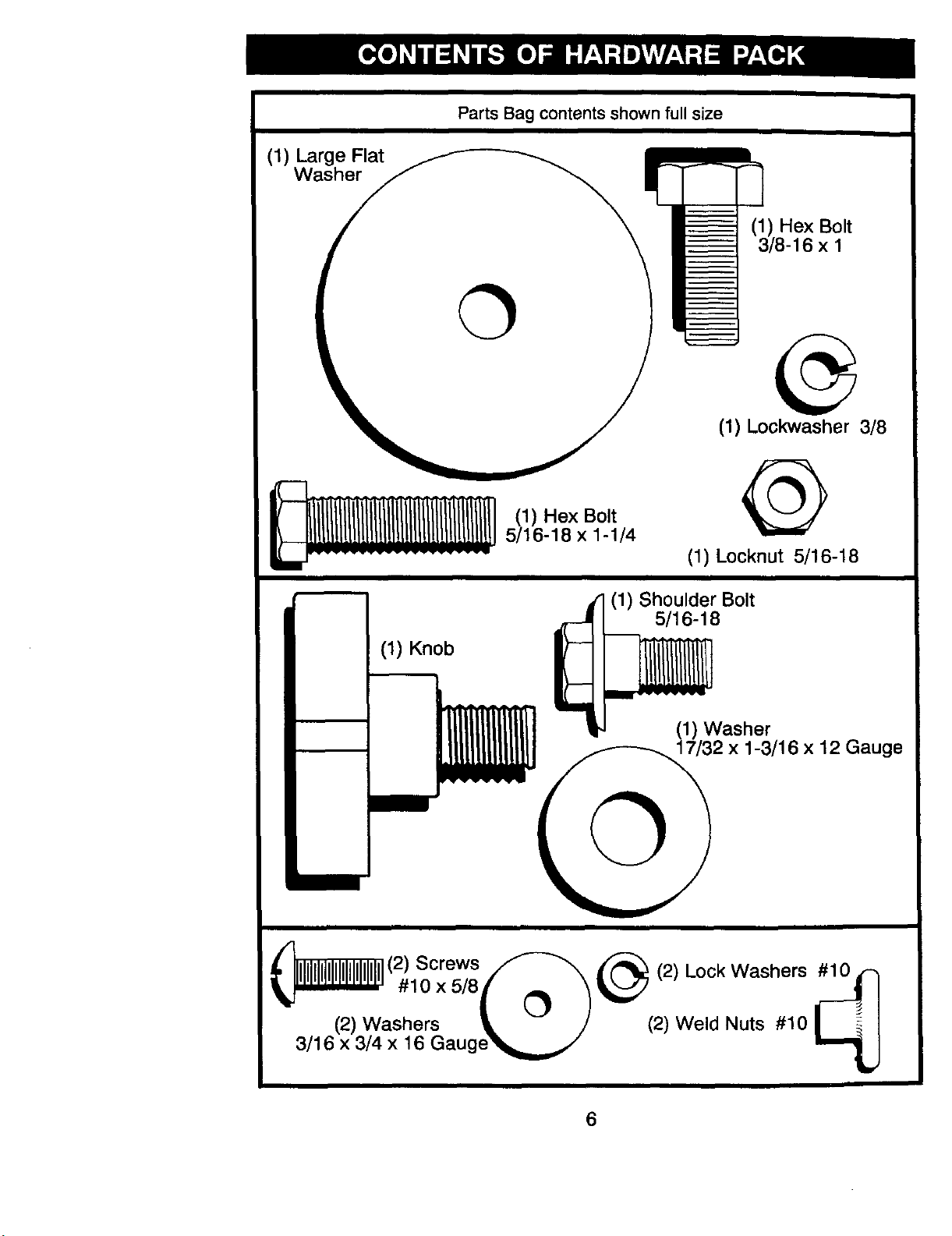
(1) Large Flat
Washer
Parts Bag contents shown full size
(1) Hex Bolt
3/8-16 x 1
(1) Lockwasher 3/8
!iiiiiiiiiiiiii! ,,,.ex.o,,
5/16-18 x 1-1/4
(1) Locknut 5/16-18
(1) Knob
(1) Shoulder Bolt
5/16-18
(1) Washer
2 x 1-3/16 x 12 Gauge
(2) Screws _--_ _ (2) Lock Washers
,_ox_,_,o /_'_
(2) Washers _. -- J (2) Weld Nuts #10
3/16 x 3/4 x 16 Gauge_.,_
6
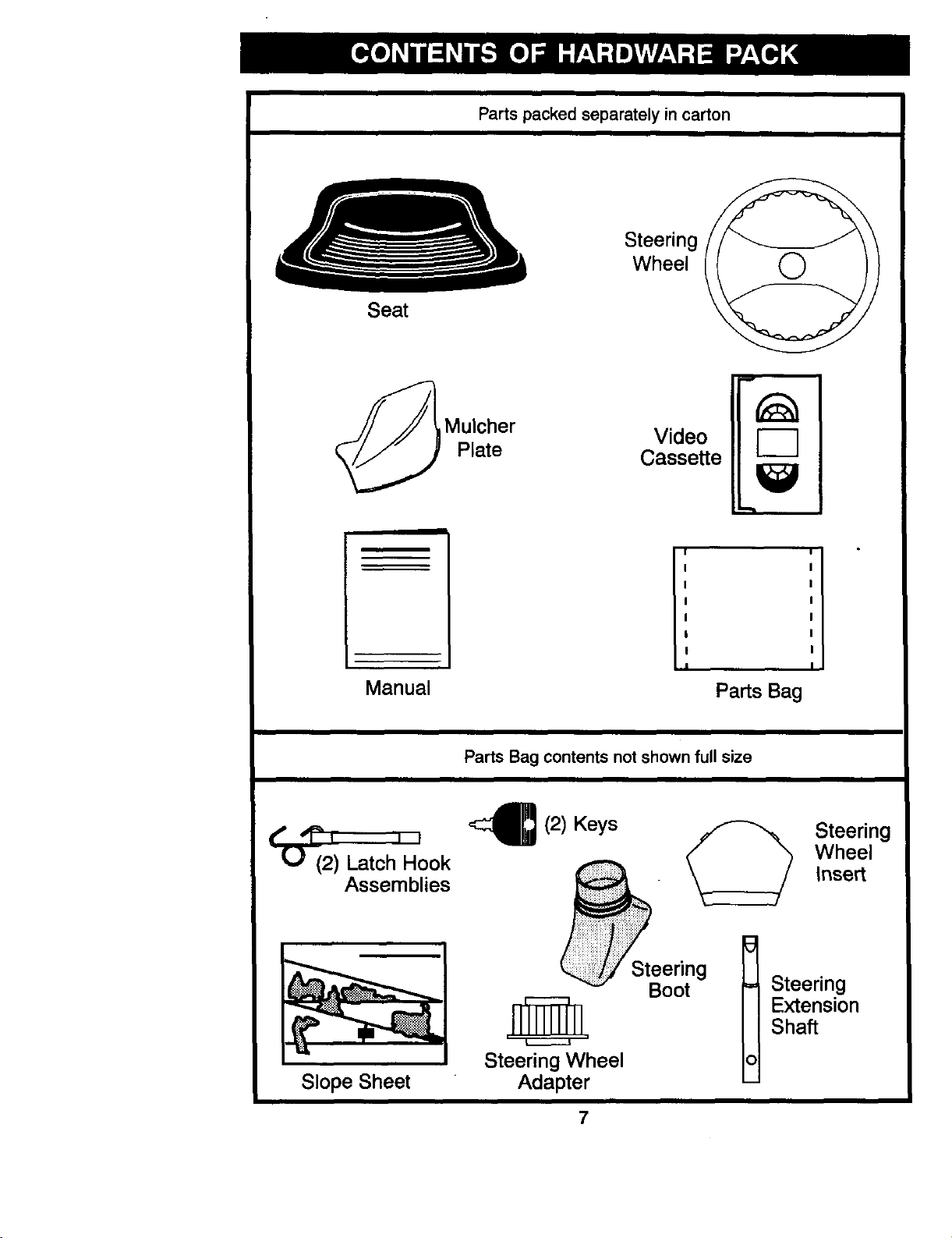
Seat
Parts packed separately in carton
Steering
Wheel
Mulcher Video
Plate Cassette
r-1
Manual
I
I
Parts Bag
Parts Bag contents not shown full size
(,-) (2) Latch Hook
Assemblies
Slope Sheet
,c_(2) Keys _ Steering
,/ \ Wheel
__ed_g _ Steering
II Extension
II Shaft
Steering Wheel Iol
Adapter
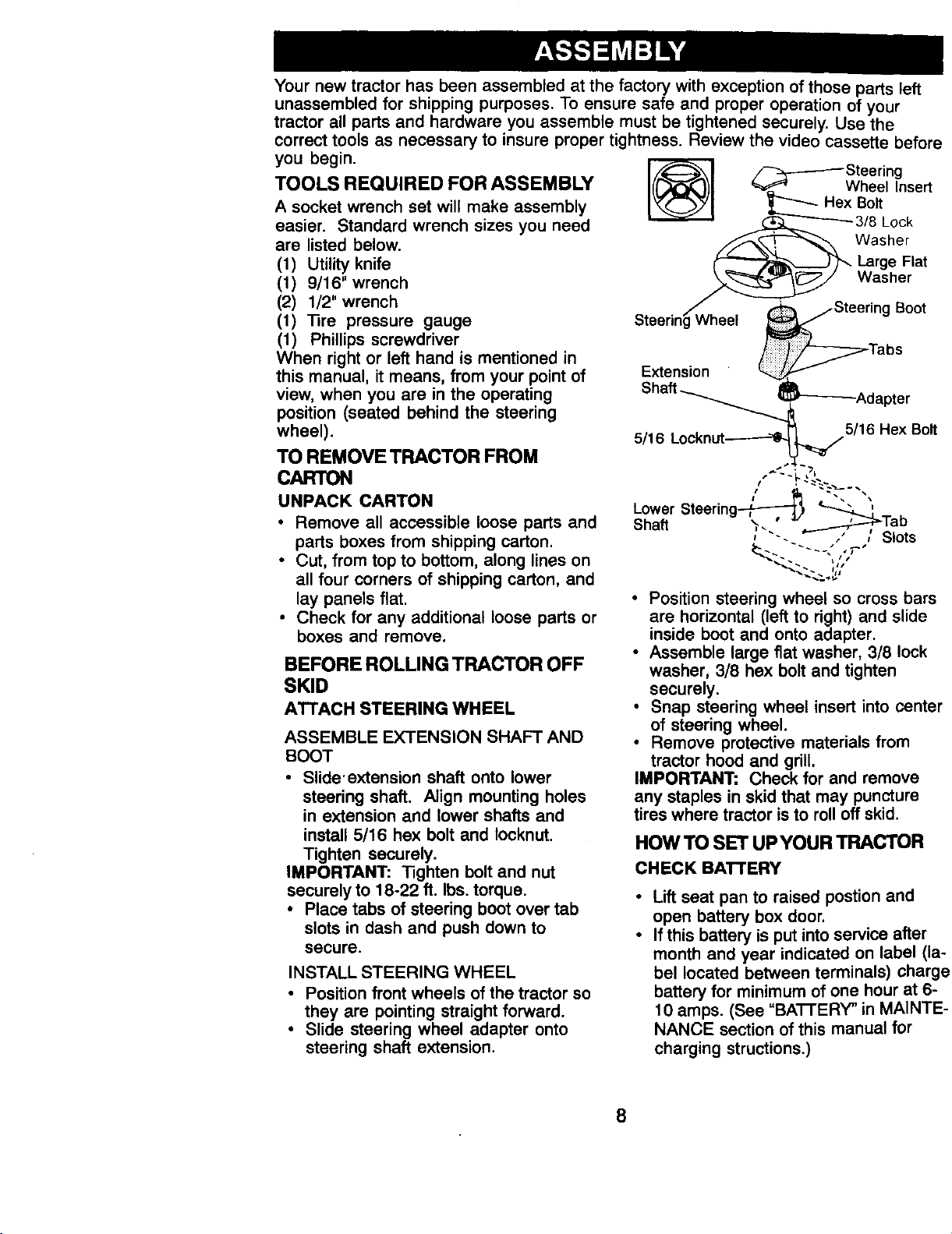
Your new tractor has been assembled at the factory with exception of those parts left
unassembled for shipping purposes. To ensure safe end proper operation of your
tractor all parts and hardware you assemble must be tightened securely. Use the
correct tools as necessary to insure proper tightness. Review the video cassette before
you begin.
TOOLS REQUIRED FOR ASSEMBLY
A socket wrench set will make assembly
easier. Standard wrench sizes you need
are listed below.
(1) Utility knife
(1) 9/16" wrench
(2) 1/2" wrench
(1) 13re pressure gauge
(1) Phillips screwdriver
When right or left hand is mentioned in
this manual, it means, from your point of
view, when you are in the operating
position (seated behind the steering
wheel).
TO REMOVE TRACTOR FROM
CARTON
UNPACK CARTON
• Remove all accessible loose parts and
parts boxes from shipping carton.
• Cut, from top to bottom, along lines on
all four corners of shipping carton, and
lay panels flat.
• Check for any additional loose parts or
boxes and remove.
BEFORE ROLLING TRACTOR OFF
SKID
ATTACH STEERING WHEEL
ASSEMBLE EXTENSION SHAFT AND
BOOT
• Slide'extension shaft onto lower
steering shaft. Align mounting holes
in extension and lower shafts and
install 5/16 hex bolt and locknut.
Tighten securely.
IMPORTANT: Tighten bolt and nut
securely to 18-22 ft. Ibs, torque,
• Place tabs of steering boot over tab
slots in dash and push down to
secure.
INSTALL STEERING WHEEL
• Position front wheels of the tractor so
they are pointing straight forward.
• Slide steering wheel adapter onto
steering shaft extension.
[___H ex_l_!l__gnsert
(_ jSteering Boot
Steering wneel _
/ Tabs
Extension
Shaft_._--'--_Adapter
5/16 Locknut_ 5/16 Hex Bolt
Lower Steering _-_, _'".
Sha_ .,. ° ._..___,_-rab
, "-- _,'_ / Slots
• Position steering wheel so cross bars
are horizontal (left to right) and slide
inside boot and onto adapter.
• Assemble large flat washer, 3/8 lock
washer, 3/8 hex bolt and tighten
securely.
• Snap steering wheel insert into center
of steering wheel.
• Remove protective materials from
tractor hood and grill.
IMPORTANT; Check for and remove
any staples in skid that may puncture
tires where tractor is to roll off skid.
HOW TO SET UPYOUR TRACTOR
CHECK BATTERY
Lift seat pan to raised postion and
open battery box door.
If this battery is put into service after
month and year indicated on label (la-
bel located between terminals) charge
battery for minimum of one hour at 6-
10 amps. (See "BA'I-rERY" in MAINTE-
NANCE section of this manual for
charging structions.)
8
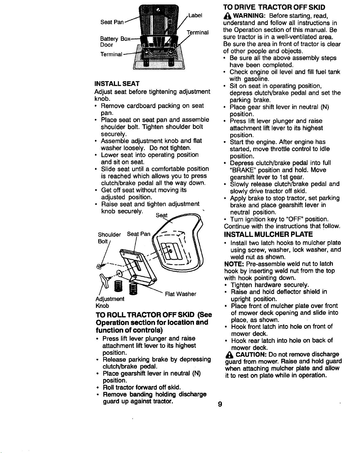
Label
Battery
Door
Terminal
INSTALL SEAT
Adjust seat before tightening adjustment
knob.
• Remove cardboard packing on seat
pan.
Place seat on seat pan and assemble
shoulder bolt. Tighten shoulder bolt
securely.
• Assemble adjustment knob and flat
washer loosely. Do not tighten.
• Lower seat into operating position
and sit on seat.
• Slide seat until a comfortable position
is reached which allows you to press
clutch/brake pedal all the way down.
• Get off seat without moving its
adjusted position.
• Raise seat and tighten adjustment
knob securely. Seat
Shoulder Seat Pan
Bolt
Flat Washer
Adjustment
Knob
TO ROLLTRACTOR OFF SKID (See
Operation section for location and
function of controls)
• Press lift lever plunger and raise
attachment lift lever to its highest
position.
• Release parking brake by depressing
clutch/brake pedal.
• Place gearshift lever in neutral (N)
position.
• Roll tractor forward off skid.
• Remove banding holding discharge
guard up against tractor.
TO DRIVE TRACTOR OFF SKID
WARNING: Before starting, read,
understand and follow all instructions in
the Operation section of this manual. Be
sure tractor is in a well-ventilated area.
Be sure the area in front of tractor is clear
of other people and objects.
• Be sure all the above assembly steps
have been completed.
• Check engine oil level and fill fuel tank
with gasoline.
• Sit on seat in operating position,
depress clutch/brake pedal and set the
parking brake.
• Place gear shift lever in neutral (N)
position.
• Press lift lever plunger and raise
attachment lift lever to its highest
position.
• Start the engine. After engine has
started, move throttle control to idle
position.
• Depress clutch/brake pedal into full
"BRAKE" position and hold. Move
gearshift lever to 1st gear.
• Slowly release clutch/brake pedal and
slowly drive tractor off skid.
• Apply brake to stop tractor, set parking
brake and place gearshift lever in
neutral position.
• Turn ignition key to "OFF' position.
Continue with the instructions that follow.
INSTALL MULCHER PLATE
Install two latch hooks to mulcher plate
using screw, washer, lock washer, and
weld nut as shown.
NOTE: Pre-assemble weld nut to latch
hook by inserting weld nut from the top
with hook pointing down.
• Tighten hardware securely.
• Raise and hold deflector shield in
upright position.
• Place front of mulcher plate over front
of mower deck opening and slide into
place, as shown.
• Hook front latch into hole on front of
mower deck.
• Hook rear latch into hole on back of
mower deck.
CAUTION: Do not remove discharge
guard from mower. Raise and hold guard
when attaching mulcher plate and allow
it to rest on plate while in operation.
9
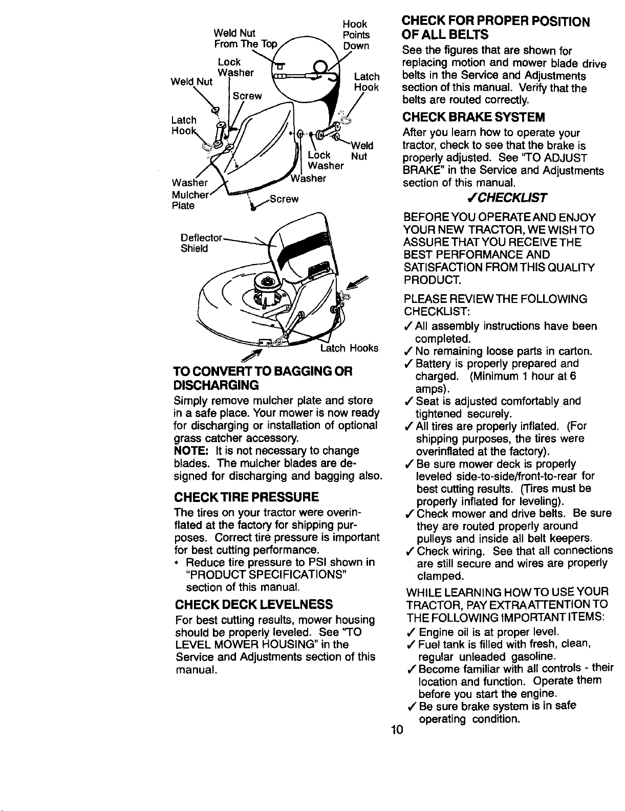
Hook
Weld Nut Points
From The To Down
Lock
Washer Latch
Weld Nut
Hook
Latch
Plate '_kl_Screw
=ck
Washer
isher
Nut
Shield
._ Latch Hooks
TO CONVERT TO BAGGING OR
DISCHARGING
Simply remove mulcher plate and store
in a safe place. Your mower is now ready
for discharging or installation of optional
grass catcher accessory.
NOTE: It is not necessary to change
blades. The mulcher blades are de-
signed for discharging and bagging also.
CHECKTIRE PRESSURE
The tires on your tractor were overin-
flated at the factory for shipping pur-
poses. Correct tire pressure is important
for best cutting performance.
• Reduce tire pressure to PSI shown in
"PRODUCT SPECIFICATIONS"
section of this manual.
CHECK DECK LEVELNESS
For best cutting results, mower housing
should be properly leveled. See 'qO
LEVEL MOWER HOUSING" in the
Service and Adjustments section of this
manual.
CHECK FOR PROPER POSITION
OF ALL BELTS
See the figures that are shown for
replacing motion and mower blade drive
belts in the Service and Adjustments
section of this manual. Verify that the
belts are routed correctly.
CHECK BRAKE SYSTEM
After you learn how to operate your
tractor, check to see that the brake is
properly adjusted. See 'q'O ADJUST
BRAKE" in the Service and Adjustments
section of this manual.
,/'CHECKLIST
BEFORE YOU OPERATE AND ENJOY
YOUR NE'3N TRACTOR, WE WISH TO
ASSURE THAT YOU RECEIVE TH E
BEST PERFORMANCE AND
SATISFACTION FROM THIS QUALITY
PRODUCT.
10
PLEASE REVIEW THE FOLLOWING
CHECKLIST:
/All assembly instructions have been
completed.
,/No remaining loose parts in carton.
,/Battery is properly prepared and
charged. (Minimum 1 hour at 6
amps).
/ Seat is adjusted comfortably and
tightened securely.
/ All tires are properly inflated. (For
shipping purposes, the tires were
overinflated at the factory).
,/"Be sure mower deck is properly
leveled side-to-side/front-to-rear for
best cutting results. (Tires must be
properly inflated for leveling).
/ Check mower and drive belts. Be sure
they are routed properly around
pulleys and inside all belt keepers.
/ Check wiring. See that all connections
are still secure and wires are properly
clamped.
WHILE LEARNING HOWTO USE YOUR
TRACTOR, PAY EXTRAAI-rENTION TO
THE FOLLOWING IMPORTANT ITEMS:
/ Engine oil is at proper level.
/ Fuel tank is filled with fresh, clean,
regular unleaded gasoline.
,/Become familiar with all controls - their
location and function. Operate them
before you start the engine.
/ Be sure brake system is in safe
operating condition.
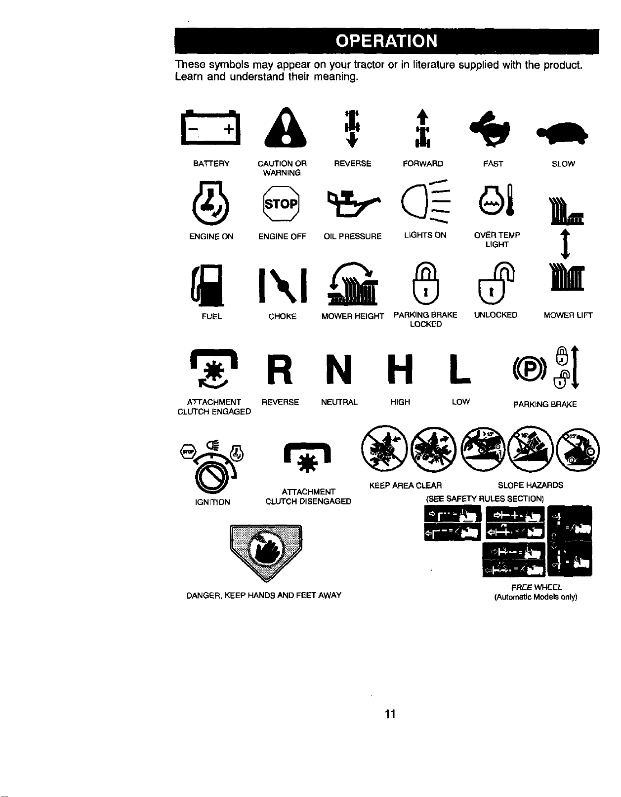
These symbols may appear on your tractor or in literature supplied with the product.
Learn and understand their meaning.
BA'rrERY CAUTION OR REVERSE FORWARD FAST SLOW
WARNING
ENGINE ON ENGINE OFF OIL PRESSURE LIGHTS ON OVER TEMP
LIGHT
FUEL CHOKE MOWER HEIGHT PARKING BRAKE UNLOCKED MOWER LIFT
LOCKED
H L
ATTACHMENT REVERSE NEUTRAL HIGH LOW PARKING BRAKE
CLUTCH ENGAGED
A'I-rACHMENT KEEP AREA CLEAR SLOPE HAZARDS
IGNITION CLUTCH DISENGAGED
DANGER, KEEP HANDS AND FEET AWAY
(SEE SAFETY RULES SECTION)
FREE WHEEL
(Automatic Models only)
11
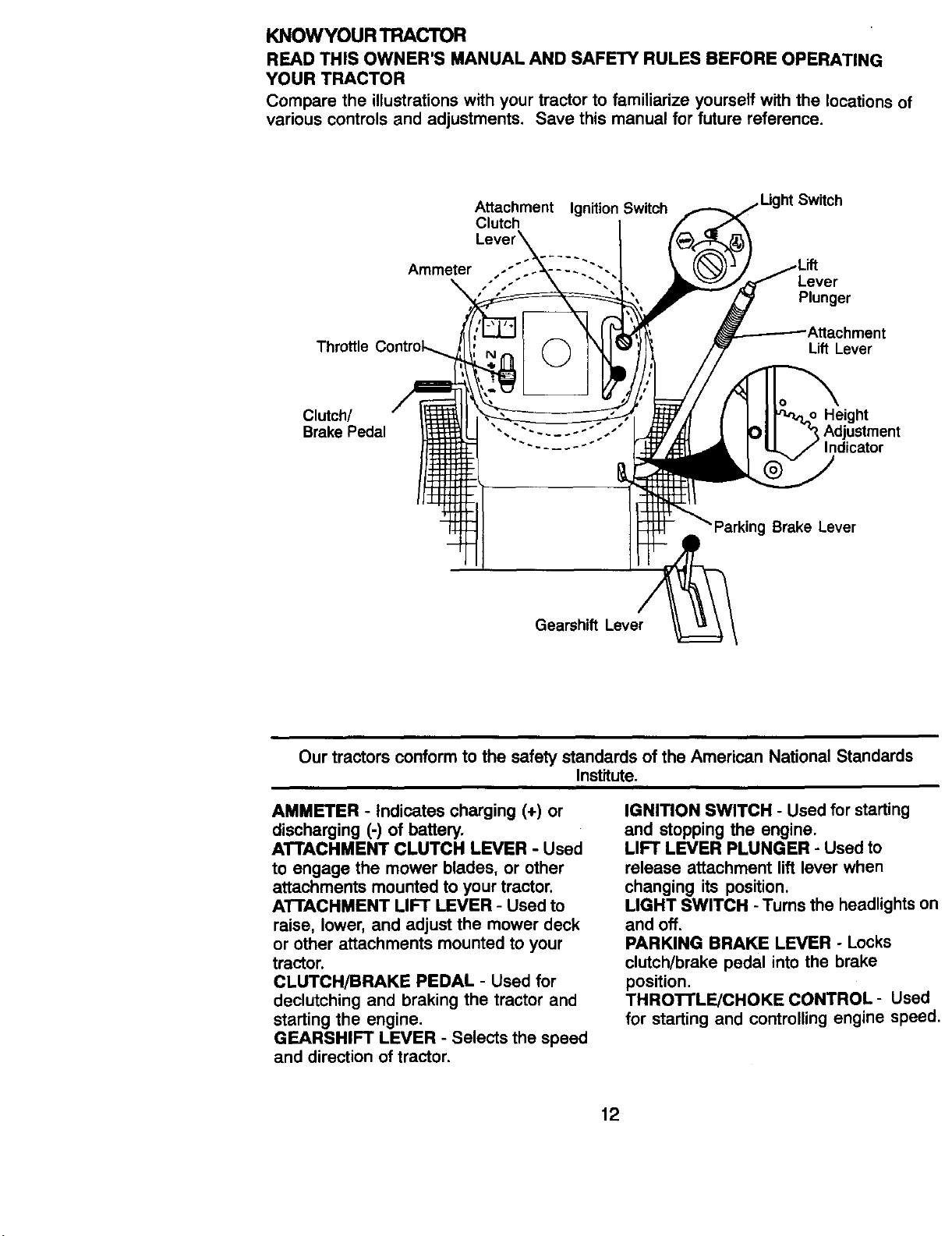
KNOWYOUR TRACTOR
READ THIS OWNER'S MANUAL AND SAFETY RULES BEFORE OPERATING
YOUR TRACTOR
Compare the illustrationswith your tractor to familiarize yourself with the locations of
various controls and adjustments. Save this manual for future reference.
Throttle
Clutch/
Brake Pedal
Attachment IgnitionSwitch
Clutch
Lew
Ammeter
Gearshift Lever
ht Switch
Lever
Plunger
Lift Lever
Brake Lever
Our tractors conform to the safety standards of the American National Standards
Institute.
AMMETER - Indicates charging (+) or
discharging (-) of battery.
ATTACHMENT CLUTCH LEVER - Used
to engage the mower blades, or other
attachments mounted to your tractor.
ATTACHMENT LIFT LEVER - Used to
raise, lower, and adjust the mower deck
or other attachments mounted to your
tractor.
CLUTCH/BRAKE PEDAL - Used for
declutching and braking the tractor and
starting the engine.
GEARSHIFT LEVER - Selects the speed
and direction of tractor.
IGNITION SWITCH - Used for starting
and stopping the engine.
LIFT LEVER PLUNGER - Used to
release attachment lift lever when
changing its position.
LIGHT SWITCH - Turns the headlights on
and off.
PARKING BRAKE LEVER - Locks
clutch/brake pedal into the brake
position.
THROTTLE/CHOKE CONTROL- Used
for starting and controlling engine speed.
12
The operation of any tractor can result in foreign objects thrown into
the eyes, which can result in severe eye damage. Always wear safety
glasses or eye shields while operating your tractor or performing any
adjustments or repairs. We recommend a wide vision safety mask
over spectacles or standard safety glasses.
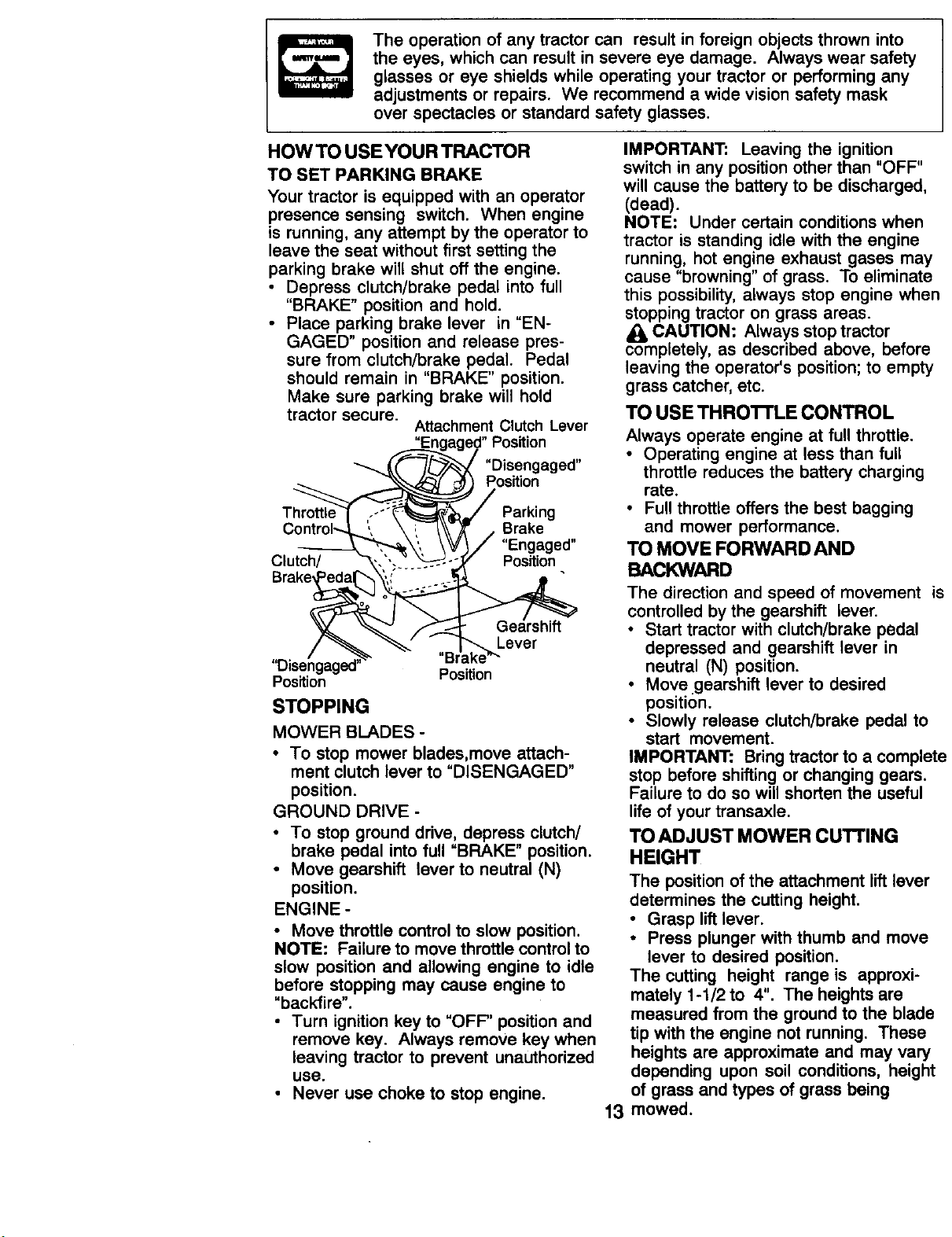
HOW TO USE YOUR TRACTOR
TO SET PARKING BRAKE
Your tractor is equipped with an operator
presence sensing switch. When engine
is running, any attempt by the operator to
leave the seat without first setting the
parking brake will shut off the engine.
• Depress clutch/brake pedal into full
"BRAKE" position and hold.
• Place parking brake lever in "EN-
GAGED" position and release pres-
sure from clutch/brake pedal. Pedal
should remain in "BRAKE" position.
Make sure parking brake will hold
tractor secure.
Attachment Clutch Lever
"Engaged" Position
__ "Disengaged"
-_ "_\"._._ _ _ Position
Park,ng
Control--.._._', \ _, /\\-_ / Brake
----_\'_ \'VI/ "Engaged"
Clutch/ "_. "'.--_-_-'-_---°.3_ Position
Brake__
_ f_'_ Gearshift
"Disengaged" =" '_"_
Position Position
STOPPING
MOWER BLADES -
• To stop mower blades,move attach-
ment clutch lever to "DISENGAGED"
position.
GROUND DRIVE -
• To stop ground drive, depress clutch/
brake pedal into full "BRAKE" position.
• Move gearshift lever to neutral (N)
position.
ENGINE -
• Move throttle control to slow position.
NOTE: Failure to move throttle control to
slow position and allowing engine to idle
before stopping may cause engine to
"backfire".
• Turn ignition key to "OFF" position and
remove key. Always remove key when
leaving tractor to prevent unauthorized
use.
• Never use choke to stop engine.
IMPORTANT: Leaving the ignition
switch in any position other than "OFF"
will cause the battery to be discharged,
(dead).
NOTE: Under certain conditions when
tractor is standing idle with the engine
running, hot engine exhaust gases may
cause "browning" of grass. To eliminate
this possibility, always stop engine when
stopping tractor on grass areas.
/k CAUTION: Always stop tractor
completely, as described above, before
leaving the operator's position; to empty
grass catcher, etc.
TO USETHROTI'LECONTROL
Always operate engine at full throttle.
• Operating engine at less than full
throttle reduces the battery charging
• rate.
Full throttle offers the best bagging
and mower performance.
TO MOVE FORWARD AND
BACKWARD
The direction and speed of movement is
controlled by the gearshift lever.
• Start tractor with clutch/brake pedal
depressed and gearshift lever in
neutral (N) position.
• Move.gearshift lever to desired
position.
• Slowly release clutch/brake pedal to
start movement.
IMPORTANT: Bring tractor to a complete
stop before shifting or changing gears.
Failure to do so will shorten the useful
life of your transaxle.
TO ADJUST MOWER CUTrlNG
HEIGHT
13
The position of the attachment lift lever
determines the cutting height.
• Grasp lift lever.
• Press plunger with thumb and move
lever to desired position.
The cutting height range is approxi-
mately 1-1/2 to 4". The heights are
measured from the ground to the blade
tip with the engine not running. These
heights are approximate and may vary
depending upon soil conditions, height
of grass and types of grass being
mowed.
• The average lawn should be cut to
approximately 2-1/2 inches during the
cool season and to over 3 inches
during hot months. For healthier and
better looking lawns, mow often and
after moderate growth.
• For best cutting performance, grass
over 6 inches in height should be
mowed twice. Make the first cut
relatively high; the second to desired
height.
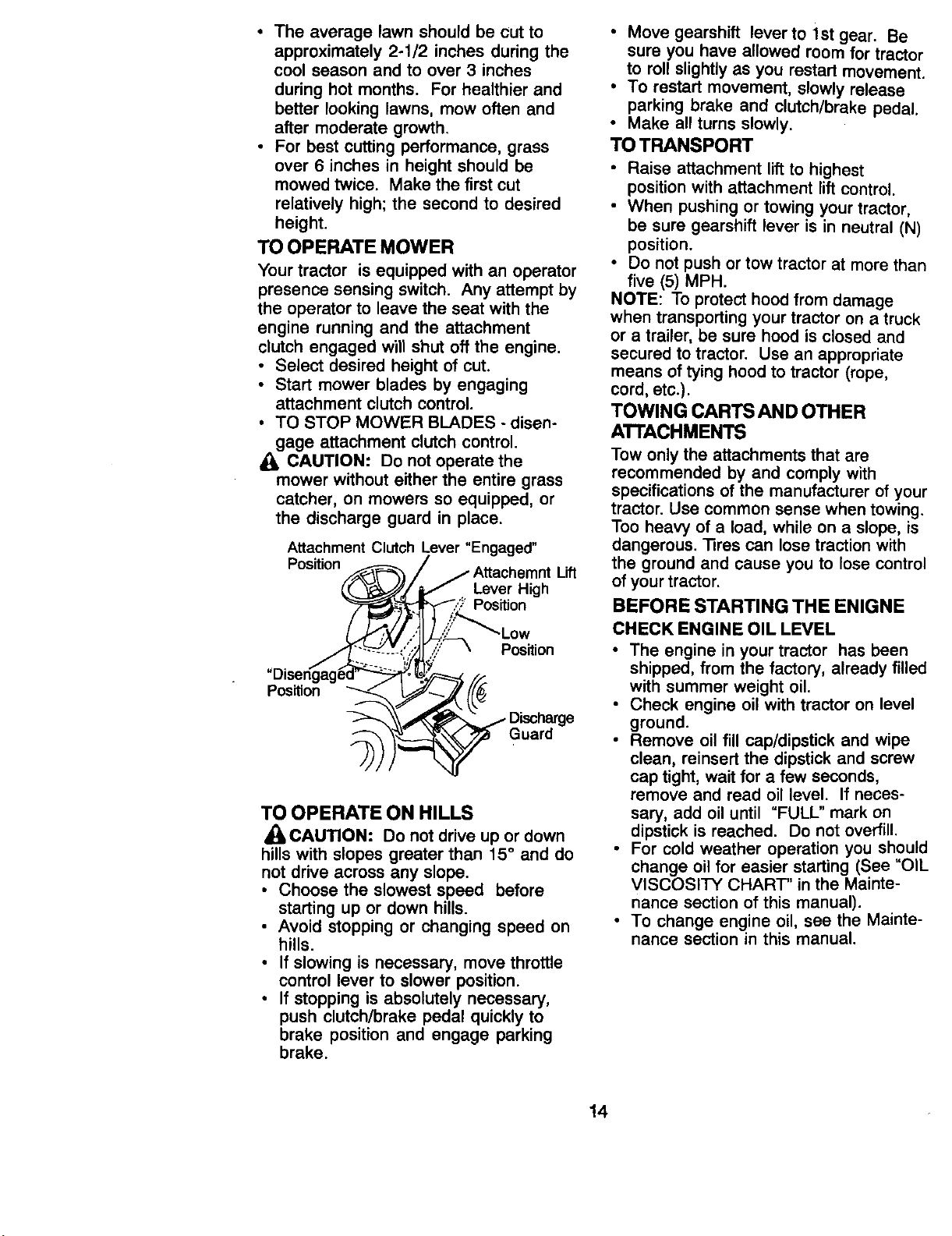
TO OPERATE MOWER
Your tractor is equipped with an operator
presence sensing switch. Any attempt by
the operator to leave the seat with the
engine running and the attachment
clutch engaged will shut off the engine.
• Select desired height of cut.
• Start mower blades by engaging
attachment clutch control.
• TO STOP MOWER BLADES - disen-
gage attachment clutch control.
CAUTION: Do not operate the
mower without either the entire grass
catcher, on mowers so equipped, or
the discharge guard in place.
Attachment Clutoh Lever "Engaged"
Position,/_! _ / / Attachemnt Lift
_.(._._Y,,_/_ . Lever High
'--/Y--Z;;_'_-_ Position
"Oisen_ag_ _. _.'_._ /..:
TO OPERATE ON HILLS
_CAUTION: Do not drive up or down
hills with slopes greater than 15 ° and do
not drive across any slope.
• Choose the slowest speed before
starting up or down hills.
• Avoid stopping or changing speed on
hills.
• If slowing is necessary, move throttle
control lever to slower position.
• If stopping is absolutely necessary,
push clutch/brake pedal quickly to
brake position and engage parking
brake.
• Move gearshift lever to 1st gear. Be
sure you have allowed room for tractor
to roll slightly as you restart movement.
• To restart movement, slowly release
parking brake and clutch/brake pedal.
• Make all turns slowly.
TO TRANSPORT
• Raise attachment lift to highest
position with attachment lift control.
• When pushing or towing your tractor,
be sure gearshift lever is in neutral (N)
position.
• Do not push or tow tractor at more than
five (5) MPH.
NOTE: To protect hood from damage
when transporting your tractor on a truck
or a trailer, be sure hood is closed and
secured to tractor. Use an appropriate
means of tying hood to tractor (rope,
cord, etc.).
TOWING CARTSAND OTHER
ATTACHMENTS
Tow only the attachments that are
recommended by and comply with
specifications of the manufacturer of your
tractor. Use common sense when towing.
Too heavy of a load, while on a slope, is
dangerous. fires can lose traction with
the ground and cause you to lose control
of your tractor.
BEFORE STARTING THE ENIGNE
CHECK ENGINE OIL LEVEL
• The engine in your tractor has been
shipped, from the factory, already filled
with summer weight oil.
• Check engine oil with tractor on level
ground.
• Remove oil fill cap/dipstick and wipe
clean, reinsert the dipstick and screw
cap tight, wait for a few seconds,
remove and read oil level. If neces-
sary, add oil until "FULL" mark on
dipstick is reached. Do not overfill.
• For cold weather operation you should
change oil for easier starting (See "OIL
VISCOSITY CHART' in the Mainte-
nance section of this manual).
• To change engine oil, see the Mainte-
nance section in this manual.
14
ADD GASOUNE
• Fill fuel tank. Use fresh, clean, regular
unleaded gasoline with a minimum of
87 octane. (Use of leaded gasoline
will increase carbon and lead oxide
deposits and reduce valve life). Do
not mix oil with gasoline. Purchase
fuel in quantities that can be used
within 30 days to assure fuel fresh-
ness.
IMPORTANT: When operating in
temperatures below 32°F(0°C), use
fresh, clean winter grade gasoline to
help insure good cold weather starting.
a_cWARNING: Experience indicates that
ohol blended fuels (called gasohol or
using ethanol or methanol) can attract
moisture which leads to separation and
formation of acids during storage. Acidic
gas can damage the fuel system of an
engine while in storage. To avoid engine
problems, the fuel system should be
emptied before storage of 30 days or
longer. Drain the gas tank, start the
engine and let it run until the fuel lines
and carburetor are empty. Use fresh fuel
next season. See Storage Instructions
for additional information. Never use
engine or carburetor cleaner products in
the fuel tank or permanent damage may
occur.
_eCAUTION: Fill to bottom of gas tank
r neck. Do not overfill. Wipe off any
spilled oil or fuel. Do not store, spill or
use gasoline near an open flame.
TO START ENGINE
When starting the engine for the first time
or if the engine has run out of fuel, it will
take extra cranking time to move fuel
from the tank to the engine.
• Sit on seat in operating position,
depress clutch/brake pedal and set
parking brake.
• Place gear shift lever in neutral (N)
position.
• Move attachment clutch to "DISEN-
GAGED" position.
• Move throttle control to choke position.
NOTE: Before starting, read the warm
and cold starting procedures below.
• Insert key into ignition and turn key
clockwise to "START" position and
release key as soon as engine starts.
Do not run starter continuously for
more than fifteen seconds per minute.
If the engine does not start after
several attempts, move throttle control
to fast position, wait a few minutes and
try again. If engine still does not start,
move the throttle control back to the
choke position and retry.
WARM WEATHER STARTING (50 ° F and
above)
• When engine starts, move the throttle
control to the fast position.
• The attachments and ground drive can
now be used. If the engine does not
accept the load, restart the engine and
allow it to warm up for one minute
using the choke as described above.
COLD WEATHER STARTING ( 50 ° F and
below)
• When engine starts, allow engine to
run with the throttle control in the
choke position until the engine runs
roughly, then move throttle control to
fast position. This may require an
engine warm-up period from several
seconds to several minutes, depend-
ing on the temperature.
• The attachments can also be used
during the engine warm-up period.
NOTE: If at a high altitude (above 3000
feet) or in cold temperatures (below 32
F) the carburetor fuel mixture may need
to be adjusted for best engine perfor-
mance. See 'q-O ADJUST CARBURE-
TOR" in the Service and Adjustments
section of this manual.
15
MOWING TIPS
• Mower should be properly leveled for
best mowing performance. See 'frO
LEVEL MOWER HOUSING" in the
Service and Adjustments section of
this manual.
• The left hand side of mower should be
used for trimming.
• Drive so that clippings are discharged
onto the area that has been cut. Have
the cut area to the right of the tractor.
This will result in a more even distribu-
tion of clippings and more uniform
cutting.
• When mowing large areas, start by
turning to the right so that clippings will
discharge away from shrubs, fences,
driveways, etc. After one or two
rounds, mow in the opposite direction
making left hand turns until finished.
• If grass is extremely tall, it should be
mowed twice to reduce load and
possible fire hazard from dried
clippings. Make first cut relatively
high; the second to the desired height.
• Do not mow grass when it is wet. Wet
grass will plug mower and leave
undesirable clumps. Allow grass to
dry before mowing.
• Always operate engine at full throttle
when mowing to assure better mowing
performance and proper discharge of
material. Regulate ground speed by
selecting a low enough gear to give
the mower cutting performance as well
as the quality of cut desired.
• When operating attachments, select a
ground speed that will suit the terrain
and give best performance of the
attachment being used.
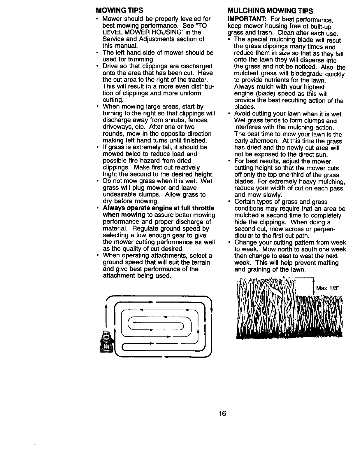
MULCHING MOWING TIPS
IMPORTANT: For best performance,
keep mower housing free of built-up
grass and trash. Clean after each use.
• The special mulching blade will recut
the grass clippings many times and
reduce them in size so that as they fall
onto the lawn they will disperse into
the grass and not be noticed. Also, the
mulched grass will biodegrade quickly
to provide nutrients for the lawn.
Always mulch with your highest
engine (blade) speed as this will
provide the best recutting action of the
blades.
• Avoid cutting your lawn when it is wet.
Wet grass tends to form clumps and
interferes with the mulching action.
The best time to mow your lawn is the
early afternoon. At this time the grass
has dried and the newly cut area will
not be exposed to the direct sun.
• For best results, adjust the mower
cutting height so that the mower cuts
off only the top one-third of the grass
blades. For extremely heavy mulching,
reduce your width of cut on each pass
and mow slowly.
• Certain types of grass and grass
conditions may require that an area be
mulched a second time to completely
hide the clippings. When doing a
second cut, mow across or perpen-
dicular to the first cut path.
• Change your cutting pattern from week
to week. Mow north to south one week
then change to east to west the next
week. This will help prevent matting
and graining of the lawn.
i
Max 113"
16
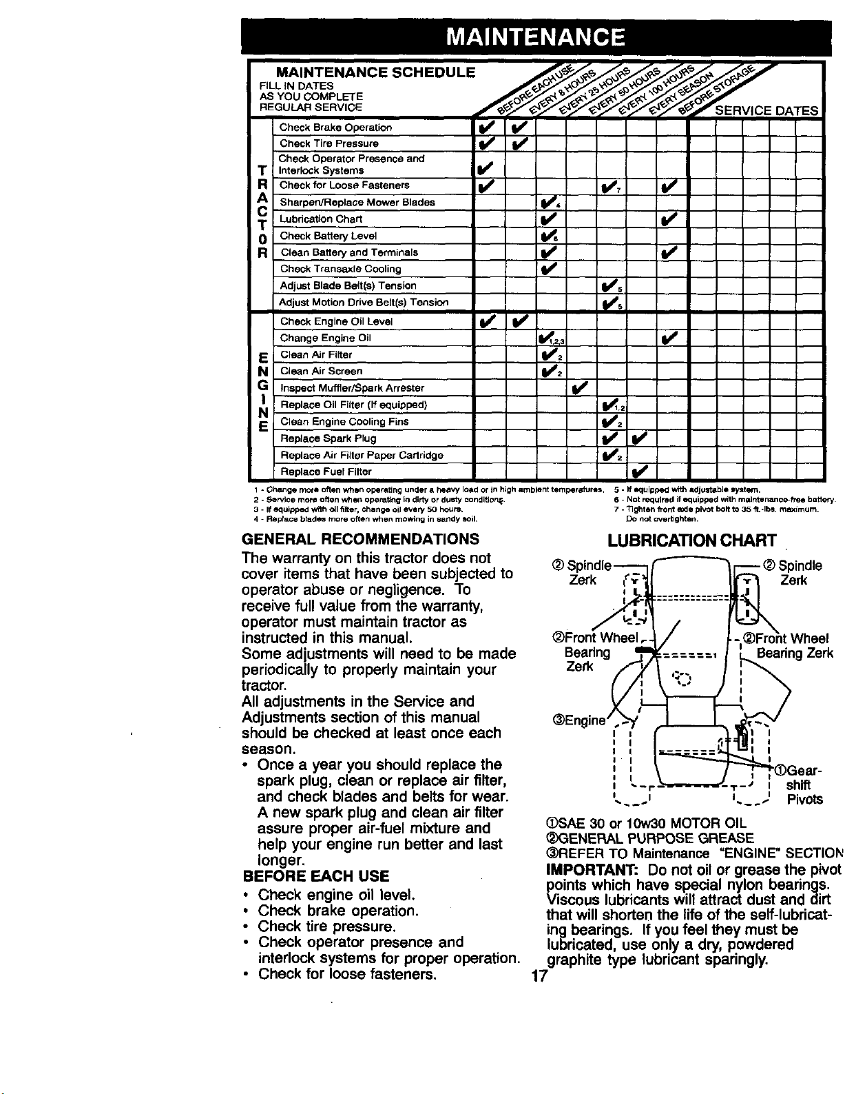
AS YOU COMPLETE .___ ___._S'__oo _ _ 4_. _*J,'j_.
Check Brake Operation _
Check Tire Pressure
Check Operator Presence and
T Interlock Systems II_
g Check for Loose Fasteners I_ I_1 I_
A Sharpen/Replace Mower Blades
T Lubrication Chart I1_
0 Check Battery Level
R Clean Battery and Terminals Ip_
Check Transaxle Cooling I1_ _
Adjust Blade Belt(s) Tension
Adjust Motion Drive Belt(s) Tension
Check Engine Oil Level _ I_
Change Engine Oil ,1_1,2,
E CleanAJr Filter
a Clean Air Screen
e Inspect Muffler/SparkArrester
NI Replace Oil Filter [if equipped) _1_1,=
S Clean Engine Cooling Fins _2
Replace Spark Plug _t_p,2 Ip_
Replace Air Filter Paper Cartridge
Replace Fuel Filter
1 - Ghwlge more often when operating under a he_y load or in high ambient temperatures, 5 - If equipped _ =_djustable systern,
2 - Service mo_ often when operating in dirty or dusty Condition_. 6 - Not required if equipped with maintenance-free battery
3 - It equipped with oil finer, chengo oil every 50 hours. 7 - Tighten front axle pivot bolt to 35 ft.-Ibs, mLximum.
4 - Replace btadu more often when mowing in sandy sell Do not overtighton.
GENERAL RECOMMENDATIONS
The warranty on this tractor does not
cover items that have been subjected to Zsrk
operator abuse or negligence. To
receive full value from the warranty,
operator must maintain tractor as
instructed in this manual. _)Front Wheel
Some adjustments will need to be made Bearing
periodically to properly maintain your Zerk
tractor.
All adjustments in the Service and
Adjustments section of this manual @Engine'
should be checked at least once each , ,
I I
season. , ,
• Once a year you should replacethe ',,'
0 I
spark plug,clean or replaceairfilter,
and check blades and belts for wear. L_.,
A new spark plug and clean air filter
assure proper air-fuel mixture and
help your engine run better and last
longer.
BEFORE EACH USE
• Check engine oil level.
• Check brake operation.
• Check tire pressure.
• Check operator presence and
interlock systems for proper operation.
• Check for loose fasteners.
LUBRICATION CHART
Zerk
Beadng Zerk
I
i
I
I
(_SAE 30 or 10w30 MOTOR OIL
_3ENERAL PURPOSE GREASE
(_REFER TO Maintenance "ENGINE" SECTIOh'
IMPORTANT: Do not oil or grease the pivot
points which have special nylon bearings.
Viscous lubricants will attract dust and dirt
that will shorten the life of the self-lubricat-
ing bearings. If you feel they must be
lubricated, use only a dry, powdered
graphite type lubricant sparingly.
17
TRACTOR
Always observe safety rules when
performing any maintenance.
BRAKE OPERATION
If tractor requires more than six (6) feet
stopping distance at high speed in
highest gear, then brake must be
adjusted. (See 'q-O ADJUST BRAKE" in
the Service and Adjustments section of
this manual).
TIRES
• Maintain proper air pressure in all tires
(See "PRODUCT SPECIFICATIONS"
section of this manual).
• Keep tires free of gasoline, oil, or
insect control chemicals which can
harm rubber.
• Avoid stumps, stones, deep ruts, sharp
objects and other hazards that may
cause tire damage.
NOTE: To seal tire punctures and
prevent flat tires due to slow leaks, tire
sealant may be purchased from your
local parts dealer. Tire sealant also
prevents tire dry rot and corrosion.
OPERATOR PRESENCE SYSTEM
Be sure operator presence and interlock
systems are working properly. If your
tractor does not function as described,
repair the problem immediately.
• The engine should not start unless the
clutch/brake pedal is fully depressed
and attachement clutch control is in
the disengaged position.
• When the engine is running, any
attempt by the operator to leave the
seat without first setting the parking
brake should shut off the engine.
• When the engine is running and the
attachment clutch is engaged, any
attempt by the operator to leave the
seat should shut off the engine.
• The attachment clutch should never
operate unless the operator is in the
seat.
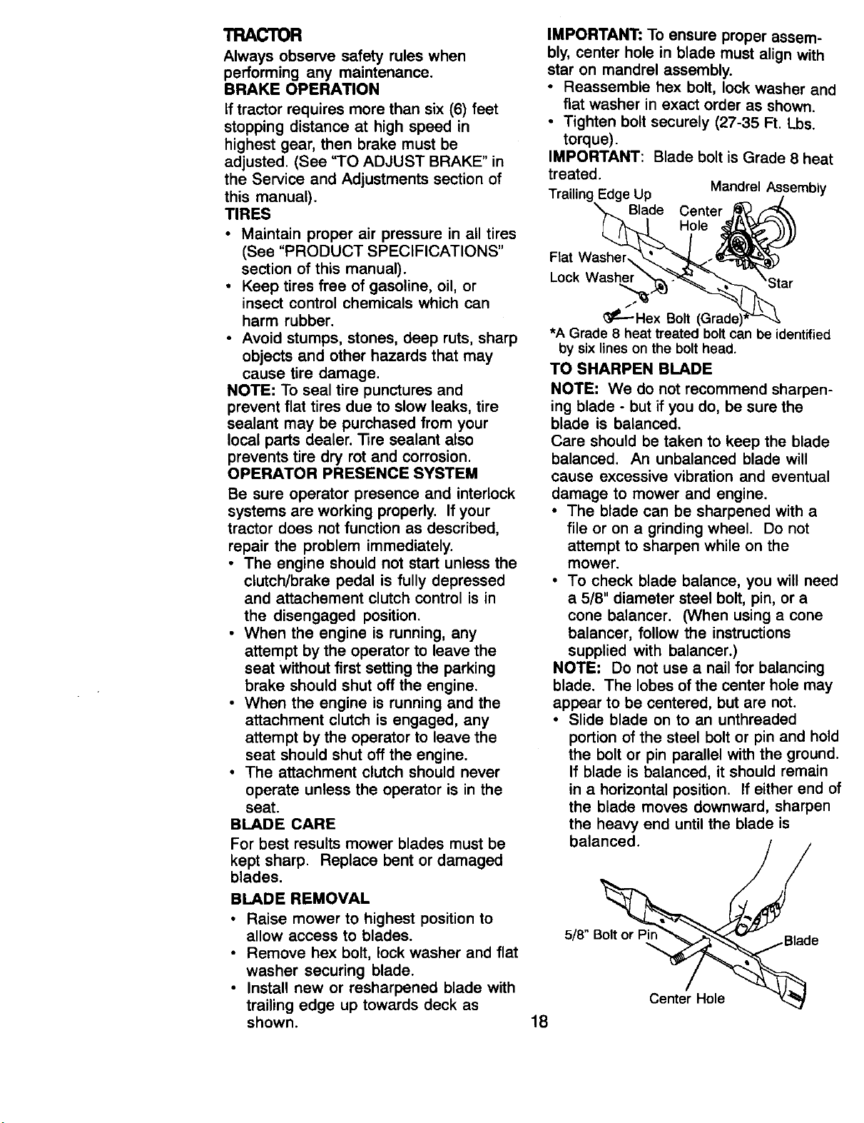
BLADE CARE
For best results mower blades must be
kept sharp. Replace bent or damaged
blades,
BLADE REMOVAL
• Raise mower to highest position to
allow access to blades.
• Remove hex bolt, lock washer and flat
washer securing blade.
• Install new or resharpened blade with
trailing edge up towards deck as
shown.
IMPORTANT: To ensure proper assem-
bly, center hole in blade must align with
star on mandrel assembly.
• Reassemble hex bolt, lock washer and
flat washer in exact order as shown.
• Tighten bolt securely (27-35 Ft. Lbs.
torque).
IMPORTANT: Blade bolt is Grade 8 heat
treated.
Trailing Edge Up Mandrel/_/sembly
X,t.._ Blade Center _ ,_----'_
( _ _ Hole .,_t'_ Y'"-_'_\\
F,atWash_ _ _)
Lock Wa_r_.He_x_ _ar
*A Grade 8 heat treated bolt can be identified
by six lines on the bolt head.
TO SHARPEN BLADE
NOTE: We do not recommend sharpen-
ing blade - but if you do, be sure the
blade is balanced.
Care should be taken to keep the blade
balanced. An unbalanced blade will
cause excessive vibration and eventual
damage to mower and engine.
• The blade can be sharpened with a
file or on a grinding wheel. Do not
attempt to sharpen while on the
mower.
• To check blade balance, you will need
a 5/8" diameter steel bolt, pin, or a
cone balancer. (When using a cone
balancer, follow the instructions
supplied with balancer.)
NOTE: Do not use a nail for balancing
blade. The lobes of the center hole may
appear to be centered, but are not.
• Slide blade on to an unthreaded
portion of the steel bolt or pin and hold
the bolt or pin parallel with the ground.
If blade is balanced, it should remain
in a horizontal position. If either end of
the blade moves downward, sharpen
the heavy end until the blade is
balanced.
5/8" B_
Center Hole
18
BATTERY
Your tractor has a battery charging
system which is sufficient for normal use.
However, periodic charging of the battery
with an automotive charger will extend
its life.
• Keep battery and terminals clean.
• Keep battery bolts tight.
• Keep small vent holes open.
• Recharge at 6-10 amperes for 1 hour.
NOTE: The original equipment battery on
your tractor is maintenance free. Do not
attempt to open or remove caps or
covers. Adding or checking level of
electrolyte is not necessary.
TO CLEAN BATTERY AND TERMINALS
Corrosion and dirt on the battery and
terminals can cause the battery to "leak"
power.
• Open battery box door.
• Disconnect BLACK battery cable first
then RED battery cable and remove
battery from tractor.
• Rinse the battery with plain water and
dry.
• Clean terminals and battery cable
ends with wire brush until bright.
• Coat terminals with grease or petro-
leum jelly.
• Reinstall battery (See "REPLACING
BATTERY" in the SERVICE AND
ADJUSTMENTS section of this
manual).
V-BELTS
Check V-belts for deterioration and wear
after 100 hours of operation and replace
if necessary. The belts are not adjustable.
Replace belts if they begin to slip from
wear.
TRANSAXLE COOLING
Keep transaxle free from build-up of dirt
and chaff which can restrict cooling.
ENGINE
LUBRICATION
Only use high quality detergent oil rated
with API service classification SF, SG or
SH. Select the oil's SAE viscosity grade
according to your expected operating
temperature.
SAE VISCOSITY GRADES
NOTE: Although multi-viscosity oils
(5W30, 10W30 etc.) improve starting in
cold weather, these multi-viscosity oils
will result in increased oil consumption
when used above 32°F. Check your en-
gine oil level more frequently to avoid
possible engine damage from running
low on oil.
Change the oil after every 25 hours of
operation or at least once a year if the
tractor is not used for 25 hours in one
year.
Check the crankcase oil level before
starting the engine and after each eight
(8) hours of operation. Tighten oil fill cap/
dipstick securely each time you check
the oil level.
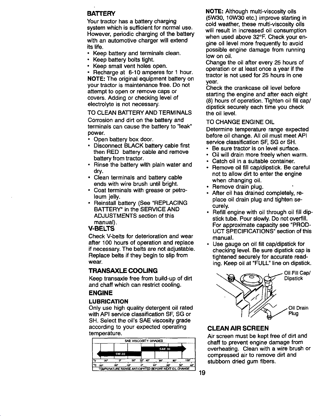
TO CHANGE ENGINE OIL
Determine temperature range expected
before oil change. All oil must meet API
service classification SF, SG or SH.
• Be sure tractor is on level surface.
• Oil will drain more freely when warm.
• Catch oil in a suitable container.
• Remove oil fill cap/dipstick. Be careful
not to allow dirt to enter the engine
when changing oil.
• Remove drain plug.
• After oil has drained completely, re-
place oil drain plug and tighten se-
curely.
• Refill engine with oil through oil fill dip-
stick tube. Pour slowly. Do not overfill.
For approximate capacity see "PROD-
UCT SPECIFICATIONS" section of this
manual.
• Use gauge on oil fill cap/dipstick for
checking level. Be sure dipstick cap is
tightened securely for accurate read-
ing. Keep oil at "FULL" line on dipstick.
Oil Fill Cap/
Dipstick
/Oil Drain
Plug
CLEAN AIR SCREEN
Air screen must be kept free of dirt and
chaff to prevent engine damage from
overheating. Clean with a wire brush or
compressed air to remove dirt and
stubborn dried gum fibers.
20* .10" O*
TEMPERATURE RANGE ANTICIPATED BEFORIENEXT OIL CHANQE
19
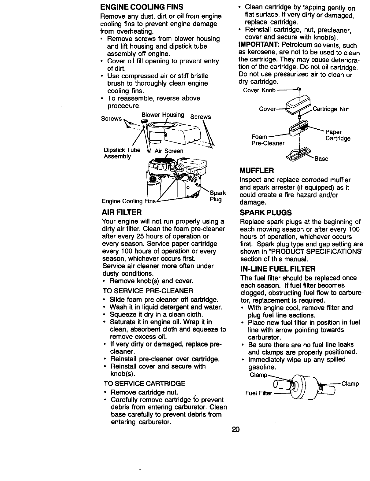
ENGINE COOUNG FINS
Remove any dust, dirt or oil from engine
cooling fins to prevent engine damage
from overheating.
• Remove screws from blower housing
and lift housing and dipstick tube
assembly off engine.
• Cover oil fill opening to prevent entry
of dirt.
• Use compressed air or stiff bristle
brush to thoroughly clean engine
cooling fins.
• To reassemble, reverse above
procedure.
S Blower Housing Screws
crewo
Dipstick T
Assembly _.
Spark
Engine Cooling Plug
AIR FILTER
Your engine will not run properly using a
dirty air filter. Clean the foam pre-cleaner
after every 25 hours of operation or
every season. Service paper cartridge
every 100 hours of operation or every
season, whichever occurs first.
Service air cleaner more often under
dusty conditions.
• Remove knob(s) and cover.
TO SERVICE PRE-CLEANER
• Slide foam pre-cleaner off cartridge.
• Wash it in liquid detergent and water.
• Squeeze it dry in a clean cloth.
• Saturate it in engine oil. Wrap it in
clean, absorbent cloth and squeeze to
remove excess oil
• If very dirty or damaged, replace pre-
cleaner.
• Reinstall pre-cleaner over cartridge.
• Reinstall cover and secure with
knob(s).
TO SERVICE CARTRIDGE
• Remove cartridge nut.
C,
• Carefully remove cartridge to prevent
debris from entering carburetor. Clean
base carefully to prevent debris from
entering carburetor.
• Clean cartridge by tapping gently on
flat surface. If very dirty or damaged,
replace cartridge.
• Reinstall cartridge, nut, precleaner,
cover and secure with knob(s).
IMPORTANT: Petroleum solvents, such
as kerosene, are not to be used to clean
the cartridge. They may cause deteriora-
tion of the cartridge. Do not oil cartridge.
Do not use pressurized air to clean or
dry cartridge.
Cover Knob
Cover--_ _Cartridge Nut
Foam _ _'"_ Paper
Pre-Cleaner .._ Cartridge
_'Base
MUFFLER
Inspect and replace corroded muffler
and spark arrester (if equipped) as it
could create a fire hazard and/or
damage.
SPARK PLUGS
Replace spark plugs at the beginning of
each mowing season or after every 100
hours of operation, whichever occurs
first. Spark plug type and gap setting are
shown in "PRODUCT SPECIFICATIONS"
section of this manual.
IN-LINE FUEL FILTER
The fuel filter should be replaced once
each season. If fuel filter becomes
clogged, obstructing fuel flow to carbure-
tor, replacement is required.
• With engine cool, remove filter and
plug fuel line sections.
• Race new fuel filter in position in fuel
line with arrow pointing towards
carburetor.
• Be sure there are no fuel line leaks
and clamps are properly positioned.
• Immediately wipe up any spilled
gasoline.
Clamp_
_-_) // _--'- Clamp
Fuel Filter
2O
CLEANING
i lean engine, battery, seat, finish, etc.
of all foreign matter.
Keep finished surfaces and wheels
free of all gasoline, oil, etc.
Protect painted surfaces with automo-
tive type wax.
We do not recommend using a garden
hose to clean your tractor unless the
electrical system, muffler, air filter and
carburetor are covered to keep water out.
Water in engine can result in a short-
ened engine life.
._CAUTION: Before performing any service or adjustments:
Depress clutch/brake pedal fully and set parking brake.
• Place gearshift lever in neutral (N) position.
• Place attachment clutch in "DISENGAGED" position.
Turn ignition key "OFF" and remove key.
Make sure the blades and all moving parts have completely stopped.
• Disconnect spark plug wire from spark plug and place wire where it cannot
come in contact with plug.
TRACTOR
TO REMOVE MOWER
Mower will be easier to remove from the
right side of tractor.
• Place attachment clutch in "DISEN-
GAGED" position.
• Move attachment lift lever forward to
lower mower to its lowest position.
Roll belt off engine pulley.
Disconnect clutch rod from clutch lever
by removing retainer spring.
• Disconnect anti-sway bar from chassis
bracket by removing retainer spring,
• Disconnect suspension arms from rear
deck brackets by removing retainer
springs.
• Disconnect front links from deck by
removing retainer springs.
• Raise lift lever to raise suspension
arms. Slide mower out from under
tractor.
IMPORTANT: If an attachment other
than the mower deck is to be mounted
on the tractor, remove the front links.
TO INSTALL MOWER
• Raise attachment lift lever to its
highest position.
• Slide mower under tractor with
discharge guard to right side of tractor.
• Lower lift lever to its lowest position.
• Install mower in reverse order of
removal instructions.
TO LEVEL MOWER HOUSING
Adjust the mower while tractor is parked
on level ground or driveway. Make sure
tires are properly inflated (See "PROD-
UCT SPECIFICATIONS" section of,this
manual). If tires are over or
underinflated, you will not properly
adjust your mower.
Lever
Clutch
Suspension
Front Link
Retainer Spdngs
(Both Sides)
Anti-Sway
Retainer Springs
(Both Sides)
21
SIDE-TO-SIDE ADJUSTMENT
Raise mower to its highest position.
• At the midpoint of both sides of mower,
measure height from bottom edge of
mower to ground. Distance "A" on
both sides of mower should be the
same or within 1/4" of each other.
• If adjustment is necessary, make
adjustment on one side of mower only.
• To raise one side of mower, tighten lift
link adjustment nut on that side.
• To lower one side of mower, loosen lift
link adjustment nut on that side.
NOTE: Each full turn of adjustment nut
will change mower height about 1/8".
• Recheck measurements after adjust-
ing.
B " Bottom edge of
or[om _ _ ,r---=m w r
edge°f I I/_!l i t_)o e
mower t_ i_u_,=_ _-._1 _ r n-
ground,_-----_---_ ou o
A-'_'-_J- Ground Line _"'"jT-_
Suspension
• To raise front of mower, loosen nut "F"
from trunnion on both front links.
Tighten nut "E" on both front links an
equal number of turns.
• When distance "D" is 1/8" to 1/2" lower
at front than rear, tighten nut "F'
against trunnion on both front links.
• Recheck side-to-side adjustment.
"D" "D"
Both Front Links Should be Equal in Length
Nut
Lift Link Adjustment Nut
FRONT-TO-BACK ADJ USTM ENT
IMPORTANT: Deck must be level side-to
side. If the following front-to-back
adjustment is necessary, be sure to
adjust both front links equally so mower
will stay level side-to-side.
To obtain the best cutting results, the
mower housing should be adjusted so
that the front is approximately 1/8" to 1/2"
lower than the rear when the mower is in
its highest position.
Check adjustment on right side of tractor.
Measure distance "D" directly in front
and behind the mandrel at bottom edge
of mower housing as shown.
• Before making any necessary adjust-
ments, check that both front links are
equal in length. Both links should be
approximately 10-3/8".
• If links are not equal in length, adjust
one link to same length as other link.
• To lower front of mower loosen nut "E"
on both front links an equal number of
turns.
• When distance "D" is 1/8" to 1/2" lower
at front than rear, tighten nuts "F"
against trunnion on both front links.
Front Links
TO REPLACE MOWER BLADE
DRIVE BELT
The mower blade drive belt may be
replaced without tools. Park the tractor
on level surface. Engage parking brake.
BELT REMOVAL-
• Remove mower from tractor (See "TO
REMOVE MOWER" in this section of
this manual).
• Work belt off both mandrel pulleys and
idler pulleys.
• Pull belt away from mower.
Mandrel
Pulley Idler
22
BELT INSTALLATION -
• Install new belt in reverse order of
removal.
• Make sure belt is in all pulley grooves
and inside all belt guides.
• Install mower in reverse order of
removal instructions.
TO ADJUST BRAKE
Your tractor is equipped with an adjust-
able brake system which is mounted on
the right side of the transaxle.
If tractor requires more than six (6) feet
stopping distance at high speed in
highest gear, then brake must be
adjusted.
• Depress clutch/brake pedal and
engage parking brake.
• Measure distance between brake
operating arm and nut "A" on brake
rod.
• If distance is other than 1-1/2", loosen
jam nut and turn nut "A" until distance
becomes 1-1/2". Retighten jam nut
against nut "A".
• Road test tractor for proper stopping
distance as stated above. Readjust if
necessary. If stopping distance is still
greater than six (6) feet in highest
gear, further maintenance is neces-
sary. Contact your nearest authorized
service center/department.
With Parking Brake "Engaged"
Nut "A"
Jam Nut
- Operating
Arm
Remove belt from stationary idler and
clutching idler.
Pull belt slack toward rear of tractor.
Remove belt upwards from transaxle
pulley by deflecting belt keepers.
Pull belt toward front of tractor and
remove downwards from around
engine pulley.
Install new belt by reversing above
procedure.
Engine Pulley--
Clutching Idler I
TRANSAXLE GEAR SHIFT LEVER
NEUTRAL ADJUSTMENT
The transaxle should be in neutral when
the gear shift lever is in neutral (N) (lock
gate) position. The adjustment is preset
at the factory; however, if adjustment is
needed, proceed as follows:
• Make sure transaxle is in neutral (N).
NOTE: When the tractor rear wheels
move freely, the transaxle is in neutral.
• Loosen adjustment bolt in front of the
right rear wheel.
• Position the gear shift lever in the
neutral (N) position.
• Tighten adjustment bolt securely.
NOTE: If additional clearance is needed
to get to adjustment bolt, move mower
deck height to the lowest position.
Neutral Lock Gate
TO REPLACE MOTION DRIVE BELT
Park the tractor on level surface. Engage
parking brake. For assistance, there is a
belt installation guide decal on bottom
side of left footrest.
• Remove mower (See 'q'O REMOVE
MOWER" in this section of this
manual.)
23
Adj Bolt
TO ADJUST STEERING WHEEL
AUGNMENT
if steering wheel crossbars are not
horizontal (left to right) when wheels are
positioned straight forward, remove
steering wheel and reassemble per
instructions in the Assembly section of
this manual.
FRONT WHEEL TOE-IN/CAMBER
The front wheel toe-in and camber are
not adjustable on your tractor. If damage
has occurred to affect the front wheel
toe-in or camber, contact your nearest
authorized service center/department.
TO REMOVE WHEEL FOR REPAIRS
• Block up axle securely.
• Remove axle cover, retaining ring and
washers to allow wheel removal (rear
wheel contains a square key - Do not
lose).
• Repair tire and reassemble.
• On rear wheels only: align grooves in
rear wheel hub and axle. Insert
square key.
• Replace washers and snap retaining
ring securely in axle groove.
• Replace axle cover.
NOTE: To seal tire punctures and
prevent flat tires due to slow leaks, tire
sealant may be purchased from your
local parts dealer. Tire sealant also
prevents tire dry rot and corrosion.
Washers
Retaining
If "jumper cables" are used for emer-
gency starting, follow this procedure:
IMPORTANT: Your tractor is equipped
with a 12 volt negative grounded system.
The other vehicle must also be a 12 volt
negative grounded system. Do not use
your tractor battery to start other vehicles.
TO ATTACH JUMPER CABLES -
• Connect each end of the RED cable to
the POSITIVE (+) terminal of each
battery, taking care not to short against
chassis.
• Connect one end of the BLACK cable
to the NEGATIVE (-) terminal of fully
charged battery.
• Connect the other end of the BLACK
cable to good CHASSIS GROUND,
away from fuel tank and battery.
TO REMOVE CABLES, REVERSE
ORDER -
• BLACK cable first from chassis and
then from the fully charged battery.
• RED cable last from both batteries.
PositiveTerminal
Negative Terminal
Axle
Cover
Square Key--_
(Rear Wheel Only)
TO START ENGINE WITH AWEAK
BAI"FERY
_CAUTION: Lead-acid batteries
generate explosive gases. Keep sparks,
flame and smoking materials away from
batteries. Always wear eye protection
when around batteries.
If your battery is too weak to start the
engine, it should be recharged. (See
"BATTERY" in the MAINTENANCE
section of this manual).
24
Battery
PositiveTerminal
Negative Terminal
REPLACING BA'n'ERY
/ILCAUTION: Do not short battery
terminals by allowing a wrench or any
other object to contact both terminals at
the same time. Before connecting battery,
remove metal bracelets, wristwatch
bands,rings,etc.
Positive terminal must be connected first
to prevent sparking from accidental
grounding.
• Lift seat pan to raised position and
open battery box door.
• Disconnect BLACK battery cable first
then RED battery cable and carefully
remove battery from tractor.
• Install new battery with terminals in
same position as old battery.
• First connect RED battery cable to
positive (+) terminal with hex bolt and
nut as shown. Tighten securely.
• Connect BLACK grounding cable to
negative (-) terminal with remaining
hex bolt and nut. Tighten securely.
• Close battery box door.
Seat Pan/
Battery
Door
Keps_ Hex
Nut _L Bolt
Positive (Red) Cable Negative (Black)
Cable
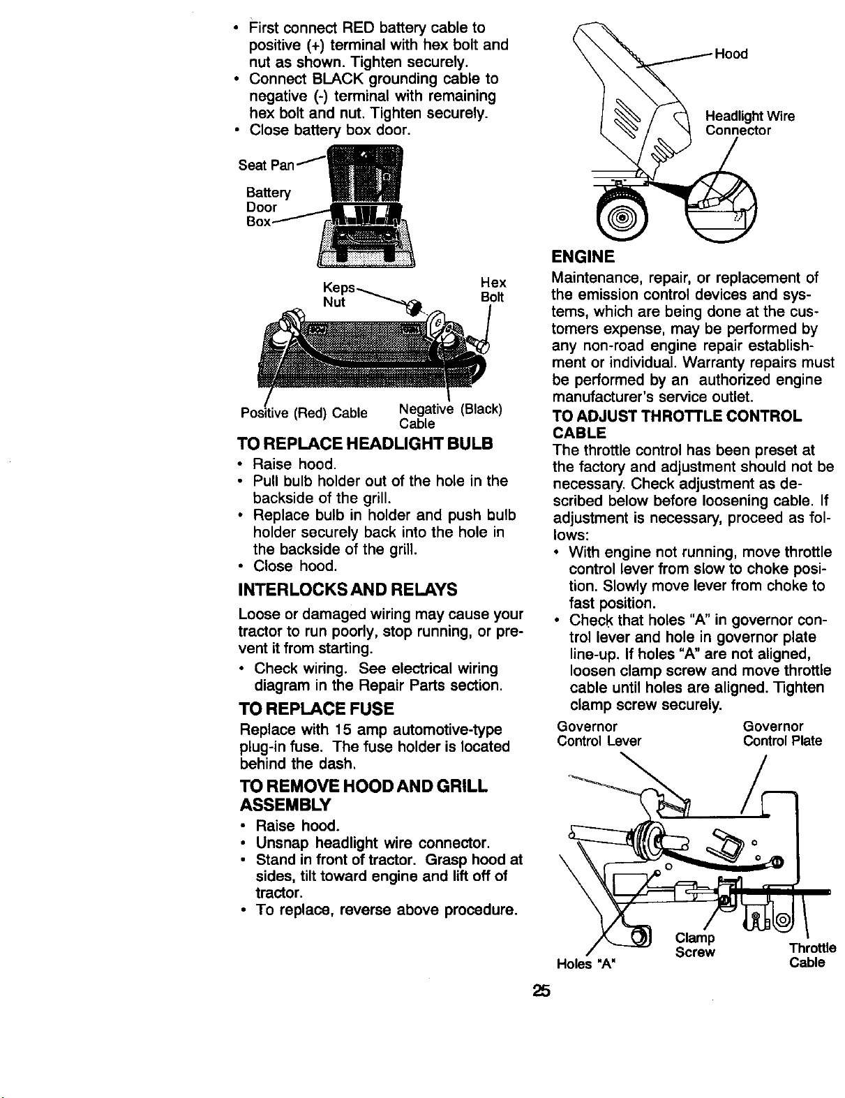
TO REPLACE HEADLIGHT BULB
• Raise hood.
• Pull bulb holder out of the hole in the
backside of the grill.
• Replace bulb in holder and push bulb
holder securely back into the hole in
the backside of the grill.
• Close hood.
INTERLOCKS AND RELAYS
Loose or damaged wiring may cause your
tractor to run poorly, stop running, or pre-
vent itfrom starting.
• Check wiring. See electrical wiring
diagram in the Repair Parts section.
TO REPLACE FUSE
Replace with 15 amp automotive-type
plug-in fuse. The fuse holder is located
behind the dash.
TO REMOVE HOOD AND GRILL
ASSEMBLY
• Raise hood.
• Unsnap headlight wire connector.
• Stand infront oftractor. Grasp hood at
sides, tilt toward engine and liftoff of
tractor.
• To replace, reverse above procedure.
or
ENGINE
Maintenance, repair, or replacement of
the emission control devices and sys-
tems, which are being done at the cus-
tomers expense, may be performed by
any non-road engine repair establish-
ment or individual. Warranty repairs must
be performed by an authorized engine
manufacturer's service outlet.
TO ADJUST THROTTLE CONTROL
CABLE
The throttle control has been preset at
the factory and adjustment should not be
necessary. Check adjustment as de-
scribed below before loosening cable. If
adjustment is necessary, proceed as fol-
lows:
• With engine not running, move throttle
control lever from slow to choke posi-
tion. Slowly move lever from choke to
fast position.
• Check that holes "A" in governor con-
trol lever and hole in governor plate
line-up. If holes "A" are not aligned,
loosen clamp screw and move throttle
cable until holes are aligned. 13ghten
clamp screw securely.
Governor Governor
Control Lever Control Plate
\
25
Clamp
Screw Throttle
Holes "A" Cable
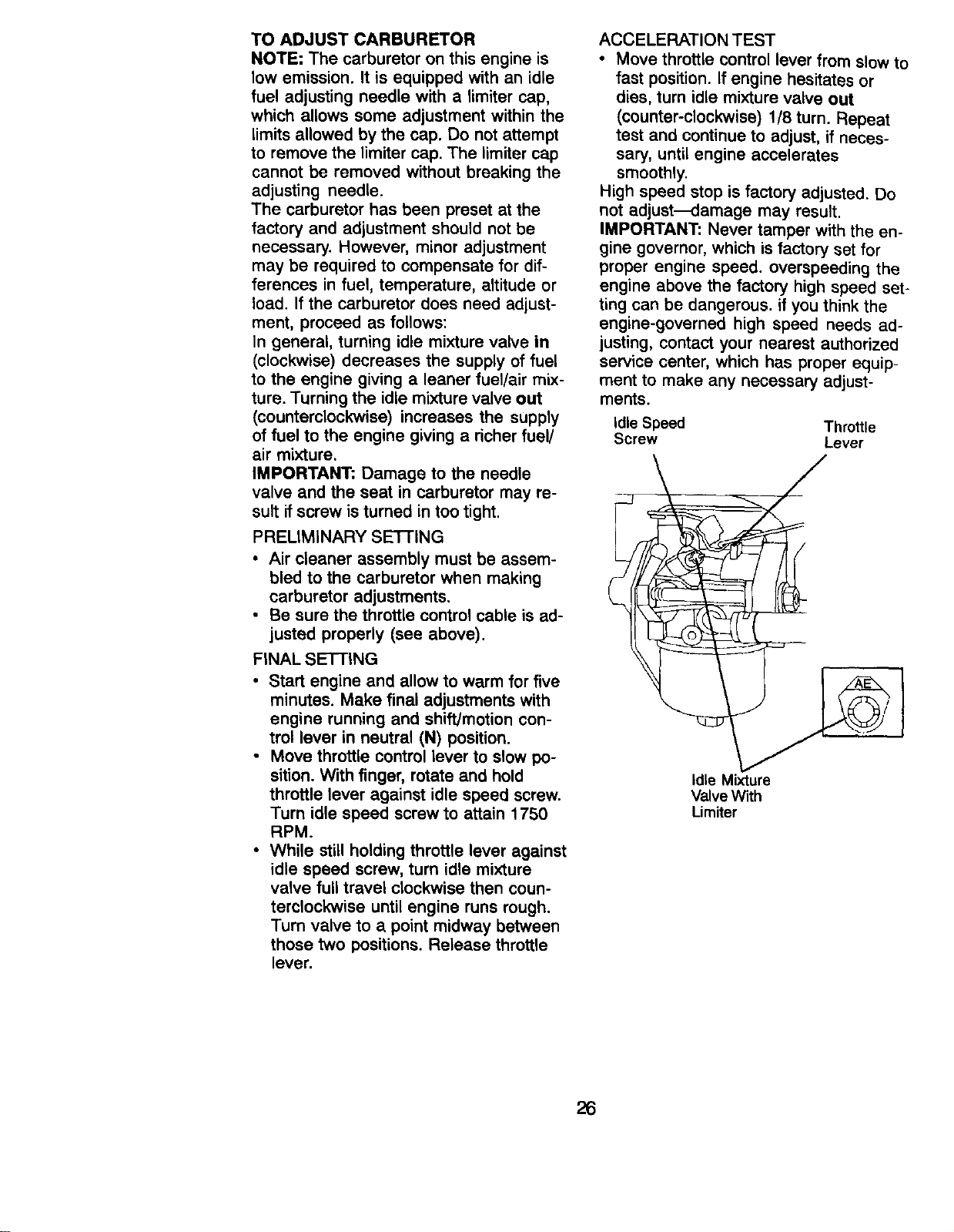
TO ADJUST CARBURETOR
NOTE: The carburetor on this engine is
low emission. It is equipped with an idle
fuel adjusting needle with a limiter cap,
which allows some adjustment within the
limits allowed by the cap. Do not attempt
to remove the limiter cap. The limiter cap
cannot be removed without breaking the
adjusting needle.
The carburetor has been preset at the
factory and adjustment should not be
necessary. However, minor adjustment
may be required to compensate for dif-
ferences in fuel, temperature, altitude or
load. If the carburetor does need adjust-
ment, proceed as follows:
In general, turning idle mixture valve in
(clockwise) decreases the supply of fuel
to the engine giving a leaner fuel/air mix-
ture. Turning the idle mixture valve out
(counterclockwise) increases the supply
of fuel to the engine giving a richer fuel/
air mixture.
IMPORTANT: Damage to the needle
valve and the seat in carburetor may re-
sult if screw is turned in too tight.
PRELIMINARY SE'I-FING
• Air cleaner assembly must be assem-
bled to the carburetor when making
carburetor adjustments.
• Be sure the throttle control cable is ad-
justed properly (see above).
FINAL SETTING
• Start engine and allow to warm for five
minutes. Make final adjustments with
engine running and shift/motion con-
trol lever in neutral (N) position.
• Move throttle control lever to slow po-
sition. With finger, rotate and hold
throttle lever against idle speed screw.
Turn idle speed screw to attain 1750
RPM.
• While still holding throttle lever against
idle speed screw, turn idle mixture
valve full travel clockwise then coun-
terclockwise until engine runs rough.
Turn valve to a point midway between
those two positions. Release throttle
lever.
ACCELERATION TEST
• Move throttle control lever from slow to
fast position. If engine hesitates or
dies, turn idle mixture valve out
(counter-clockwise) 1/8 turn. Repeat
test and continue to adjust, if neces-
sary, until engine accelerates
smoothly.
High speed stop is factory adjusted. Do
not adjust_amage may result.
IMPORTANT: Never tamper with the en-
gine governor, which is factory set for
proper engine speed, overspeeding the
engine above the factory high speed set-
ting can be dangerous, if you think the
engine-governed high speed needs ad-
justing, contact your nearest authorized
service center, which has proper equip-
ment to make any necessary adjust-
ments.
Idle Speed Throttle
Screw Lever
Idle Mixture
Valve With
Lirniter
26
Immediately prepare your tractor for
storage at the end of the season or if the
tractor will not be used for 30 days or
more.
w_ltCAUTION: Never store the tractor
h gasoline in the tank inside a
building where fumes may reach an
open flame or spark. Allow the engine to
cool before storing in any enclosure.
TRACTOR
Remove mower from tractor for winter
storage. When mower is to be stored for
a period of time, clean it thoroughly,
remove all dirt, grease, leaves, etc. Store
in a clean, dry area.
• Clean entire tractor (See "CLEANING"
in the Maintenance section of this
manual).
• Inspect and replace belts, if necessary
(See belt replacement instructions in
the Service and Adjustments section of
this manual).
• Lubricate as shown in the Mainte-
nance section of this manual.
• Be sure that all nuts, bolts and screws
are securely fastened. Inspect moving
parts for damage, breakage and wear.
Replace if necessary.
• Touch up all rusted or chipped paint
surfaces; sand lightly before painting.
BA'B'ERY
• Fully charge the battery for storage.
• After a period of time in storage,
battery may require recharging.
• To help prevent corrosion and power
leakage during long periods of
storage, battery cables should be
disconnected and battery cleaned
thoroughly (see 'q'O CLEAN BATTERY
AND TERMINALS" in the Maintenance
section of this manual).
• After cleaning, leave cables discon-
nected and place cables where they
cannot come in contact with battery
terminals.
• If battery is removed from tractor for
storage, do not store battery directly on
concrete or damp surfaces.
ENGINE
FUEL SYSTEM
IMPORTANT: It is important to prevent
]uUmdeposits from forming in essential
el system parts such as carburetor, fuel
filter, fuel hose, or tank during storage.
Also, experience indicates that alcohol
blended fuels 9called gasohol or using
ethanol or methanol) can attract moisture
which leads to separation and formation
of acids during storage. Acidic gas can
damage the fuel system of an engine
while in storage.
• Drain the fuel tank.
• Start the engine and let it run until the
fuel lines and carburetor are empty.
• Never use engine or carburetor
cleaner products in the fuel tank or
permanent damage may occur.
• Use fresh fuel next season.
NOTE: Fuel stabilizer is an acceptable
alternative in minimizing the formation of
fuel gum deposits during storage. Add
stabilizer to gasoline in fuel tank or
storage container. Always follow the mix
ratio found on stabilizer container. Run
engine at least 10 minutes after adding
stabilizer to allow the stabilizer to reach
the carburetor. Do not drain the gas tank
and carburetor if using fuel stabilizer.
ENGINEOIL
Drain oil (with engine warm) and replace
with clean engine oil. (See "ENGINE" in
the Maintenance section of this manual).
CYLINDER(S)
• Remove spark plug(s).
• Pour one ounce of oil through spark
plug hole(s) into cylinder(s).
• Turn ignition key to "START' position
for a few seconds to distribute oil.
• Replace with new spark plug(s).
OTHER
• Do not store gasoline from one season
to another.
• Replace your gasoline can if your can
starts to rust. Rust and/or dirt in your
gasoline will cause problems.
• If possible, store your tractor indoors
and cover it to give protection from
dust and dirt.
• Cover your tractor with a suitable
protective cover that does not retain
moisture. Do not use plastic. Plastic
cannot breathe which allows conden-
sation to form and will cause your
tractor to rust.
IMPORTANT: Never cover tractor while
engine and exhaust areas are still
warm.
27
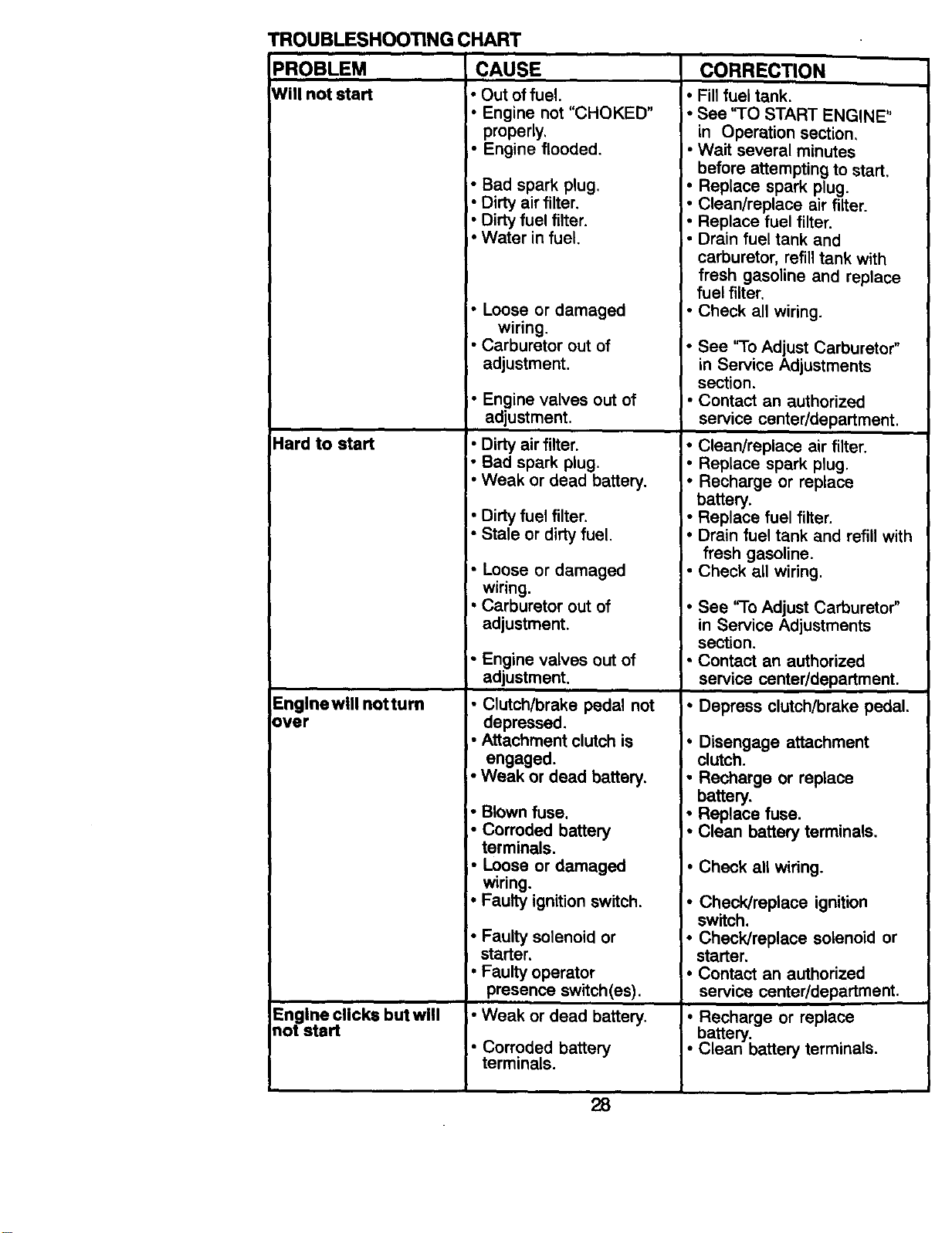
TROUBLESHOOTING CHART
PROBLEM CAUSE CORRECTION
Will not start • Out of fuel.
• Engine not "CHOKED"
properly,
_-Engine flooded.
• Bad spark plug.
• Dirty air filter.
• Dirty fuel filter.
• Water in fuel,
• Loose or damaged
wiring.
• Carburetor out of
adjustment.
Hard to start
Englnewlll notturn
over
Engine clicks but will
not start
i" Engine valves out of
adjustment.
• Dirty air filter.
• Bad spark plug.
• Weak or dead battery.
• Dirty fuel filter.
• Stale or dirty fuel.
• Loose or damaged
wiring.
• Carburetor out of
adjustment.
• Engine valves out of
adjustment,
• Clutch/brake pedal not
depressed.
• Attachment clutch is
engaged.
• Weak or dead battery.
• Blown fuse.
• Corroded battery
terminals.
• Loose or damaged
wiring.
• Faulty ignition switch.
• Faulty solenoid or
starter,
• Faulty operator
presence switch(es).
• Weak or dead battery.
• Corroded battery
terminals.
• Fill fuel tank.
• See 'qO START ENGINE"
in Operation section,
• Wait several minutes
before attempting to start,
• Replace spark plug.
• Clean/replace air filter.
• Replace fuel filter.
• Drain fuel tank and
carburetor, refill tank with
fresh gasoline and replace
fuel filter.
• Check all wiring.
• See 'rio Adjust Carburetor"
in Service Adjustments
section.
• Contact an authorized
service center/department.
• Clean/replace air filter.
• Replace spark plug.
• Recharge or replace
battery.
• Replace fuel filter.
• Drain fuel tank and refill with
fresh gasoline.
• Check all wiring.
• See 'q-o Adjust Carburetor"
in Service Adjustments
section,
• Contact an authorized
service center/department.
• Depress clutch/brake pedal.
• Disengage attachment
clutch.
• Recharge or replace
battery,
• Replace fuse.
• Clean battery terminals,
• Check all wiring.
• Check]replace ignition
switch.
• Check/replace solenoid or
starter.
• Contact an authorized
service center/department.
• Recharge or replace
battery.
• Clean battery terminals.
28
TROUBLESHOOTINGCHART
PROBLEM CAUSE
Engine clicks but will
not start (Cont'd)
Loss of power
Excessive vibration
Engine continues
to run when operator
leaves seat with
attachment clutch
engaged
Poor cut - uneven
• Loose or damaged
wiring.
• Faulty solenoid or
starter.
• Cutting too much
grass/too fast.
• Throttle in "CHOKE"
position.
• Build-up of grass,
leaves and trash
under mower.
• Dirty air filter.
• Low oil level/dirty oil.
• Faulty spark plug.
• Dirty fuel filter.
• Stale or dirty fuel.
• Water in fuel.
• Spark plug wire loose.
• Dirty engine air screen/
fins.
• Dirty/clogged muffler.
• Loose or damaged
wiring.
• Carburetor out of
adjustment.
• Engine valves out of
adjustment.
• Worn, bent or loose
blade.
• Bent blade mandrel.
• Loose/damaged part(s).
• Faulty operator-safety
presence control
system.
• Worn, bent or loose
blade.
• Mower deck not level.
• Buildup ofgrass,
leaves, and trash
under mower.
• Bent blade mandrel.
• Clogged mower deck
ventholes from buildup
of grass, leaves, and
trash around mandrels.
CORRECTION
• Check all wiring.
• Check/replace solenoid or
starter.
• Set in "Higher Cut" position/
reduce speed.
• Adjust throttle control.
• Clean underside of mower
housing.
• Clean/replace air filter,
• Check oil level/change oil.
• Clean and regap or change
spark plug.
• Replace fuel filter.
• Drain fuel tank and refill
with fresh gasoline.
• Drain fuel tank and carbure
tor, refill tank with fresh
gasoline and replace fuel
filter.
• Connect and tighten spark
plug wire.
• Clean engine air screen/fins.
• Clean/replace muffler.
• Check all wiring.
• See 'qo Adjust Carburetor"
in Service Adjustments
section.
• Contact an authorized
service center/department.
Replace blade. "13ghten
blade bolt.
Replace blade mandrel.
• Tighten loose part(s).
Replace damaged parts.
• Check wiring, switches and
connections. If not corrected,
contact an authorized
service center/department.
• Replace blade. Tighten
blade bolt.
• Level mower deck.
• Clean underside of mower
housing.
• Replace blade mandrel.
• Clean around mandrels to
open vent holes.
29
TROUBLESHOOTINGCHART
PROBLEM CAUSE CORRECTION
iMower blades will not • Obstruction in clutch • Remove obstruction.
rotate mechanism,
• Worn/damaged mower • Replace mower drive belt.
drive belt.
• Frozen idler pulley,
• Frozen blade mandrel.
Poor grass discharge • Engine speed too slow.
Headlight(s) not
working (if so
equipped)
Battery will not charge
Engine "backfires"
when turning engine
"OFF"
• Travel speed too fast.
• Wet grass.
• Mower deck not level.
• Low/uneven tire air
pressure.
• Worn, bent or loose blade.
• Buildup of grass,
leaves and trash under
mower.
• Mower drive belt worn.
• Blades improperly
installed.
• Improper blades used.
• Clogged mower deck
vent holes from buildup
of grass, leaves, and
trash around mandrels.
• Switchis "OFF".
• Bulb(s) burned out.
• Faulty light switch.
• Loose or damaged
wiring.
• Blown fuse.
• Bad battery cell(s).
• Poor cable connections.
• Faulty regulator (if so
equipped).
• Faulty alternator.
• Engine throttle control
not set at "SLOW"
position for 30 seconds
before stopping engine.
• Replace idler pulley.
• Replace blade mandrel.
• Place throttle control in
"FAST" position.
• Shift to slower speed.
• Allow grass to dry before
mowing.
• Level mower deck.
• Check tires for proper air
pressure.
• Replace/sharpen blade.
Tighten blade bolt.
• Clean underside of mower
housing.
• Replace mower drive belt.
• Reinstall blades sharp edge
down.
• Replace with blades listed
in this manual.
• Clean around mandrels to
open vent holes.
• Turn switch "ON",
• Replace bulb(s).
• Check/replace light switch.
• Check wiring and connec
tions.
• Replace fuse.
Replace battery.
I. Check/clean all connec
tions.
• Replace regulator.
• Replace alternator.
• Move throttle control to
"SLOW" position and allow
to idle for 30 seconds before
stopping engine.
30
SCHEMATIC
TRACTOR o- MODEL NUMBER 917.270650
RED
BATrERY
BLACK
I
_E. FUSE i _ ST_.TE.
(OPTIONAL) w'4mE e_cK
...... I
J I i
CLUTCH / BRAKE
r r_ )G Lt (PEDALUP)
I I SEAT SWITCH
IGNW{ONSWITCH I I ,.... I.... , { (NOT OCCUPIED)
II _ _""_ I......... ',
B I-_CK . --.. ....... I
A3_PMENT C
I I SLACK _] IGNITION _ PLUG
I :- aEL: "-1 UNIT I PLU%O
I "_ LINE I TWIN OYL. ENGIBIES) _1
i I
k_.__J _._____J
CHARGI_ _TEM OIJTPUT 21BVOLTS _d_ MIN. 3800 RP_4
3 AMp _ @ _ RPM (CHARGING SYS_ t)ISCONNECTED)
FUEL SHUT_IFF REO I" ........ f
SOLENOID [ LIG H _m_GSy'_ T_M OUTI_j T I
_NC_E 5 AMP i_C @ _RIOQ
IGNmON swrrcH
POSITION CIRCUIT _MAKE"
YOUR TRACTOR IS
EQUIPPED WITH A SPECIAL
ALTERNATOR SYSTEM.
THE LIGHTS ARE NOT
CONNECTED TO THE
BATrERY, BUT HAVE THEIR
OWN ELECTRICAL SOURCE.
BECAUSE OF THIS, THE
BRIGHTNESS OF THE LIGHTS
WILL CHANGE WITH ENGINE
SPEED. AT IOLETHE LIGHTS
WILL DIM. AS THE ENGINE IS
HEADLIGHTS
--O-- n
SPEEDED UP, THE LIGHTS NON-REMOVABLE REMOVABLE
WILL BECOME THEIR BRIGHTEST. CONNECTIONS CONNECTIONS
OFF G+M+L NONE
RUN/LIGHT B+L A+Y
RUN B + L NONE
START B + L + S NONE
WIRING INSULATED CUPS
NOTE: IF WIRING INSULATED CLIPS WERE REMOVED FOR
SERVICING OF UNIT, THEY SHOULD BE REPLACED TO
PROPERLY SECURE YOUR WIRING.
31
ELECTRICAL
TRACTOR - - MODEL NUMBER 917.270650
22
41
8
I
/
/
/
32
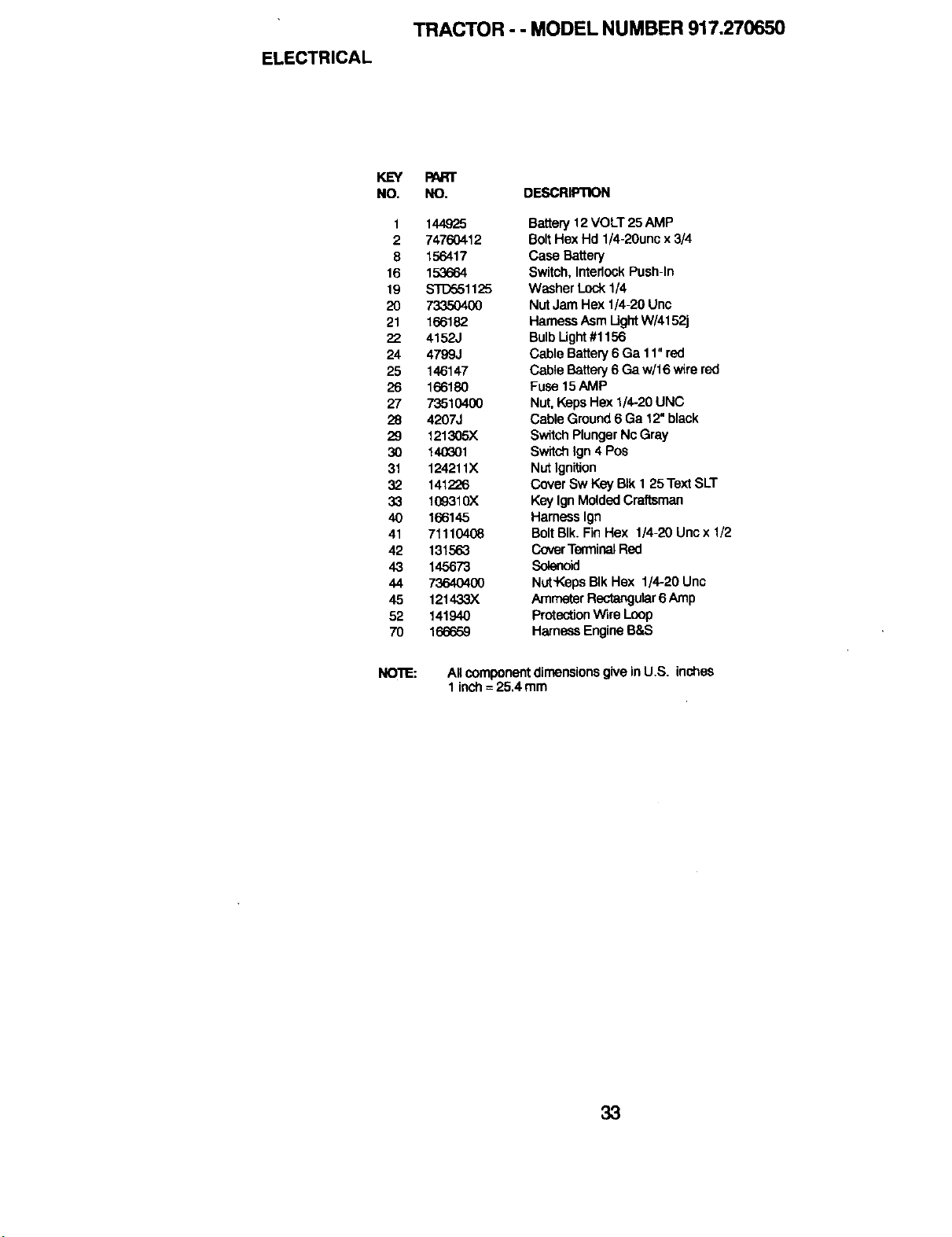
ELECTRICAL
TRACTOR - - MODEL NUMBER 917,270650
KEY
NO.
1
2
8
16
19
2O
21
22
24
25
26
27
28
29
30
31
32
33
4O
41
42
43
44
45
52
70
PART
NO. DESCRIPTION
144925
74760412
156417
153664
S'T'[To51125
7335O4O0
166182
4152J
4799J
146147
166180
73510400
4207J
121305X
140(301
124211X
141226
109.310X
166145
71110408
131563
145673
7364O4OO
121433X
141940
166659
Battery12VOLT 25 AMP
BoltHex Hd 1/4-20uncx 3/4
Case Battery
Switch, InterlockPush-In
Washer Lock1/4
Nut Jam Hex 1/4-20 Unc
HarnessAsm Ught W/4152j
BulbUght #1156
Cable Battery6 Ga 11"red
Cable Battery6 Ga w/t 6 wirered
Fuse 15AMP
Nut,KepsHex 1/4-20UNC
Cable Ground6 Ga 12"black
SwitchPlungerNc Gray
SwitchIgn 4 Pos
Nut Ignition
CoverSw Key BIk I 25 TextSLT
Key IgnMoldedCraftsman
Harness Ign
BoltBIk.Fin Hex 1/4-20 Uncx 1/2
CoverTerminalRed
Solenoid
Nut'KepsBIk Hex 1/4-20 Unc
AmmeterRectangutar6 Amp
ProtectionWire Loop
HarnessEngineB&S
NO'lIE:
Allcomponentdimensions give inU.S. inches
1inch= 25.4 mm
33
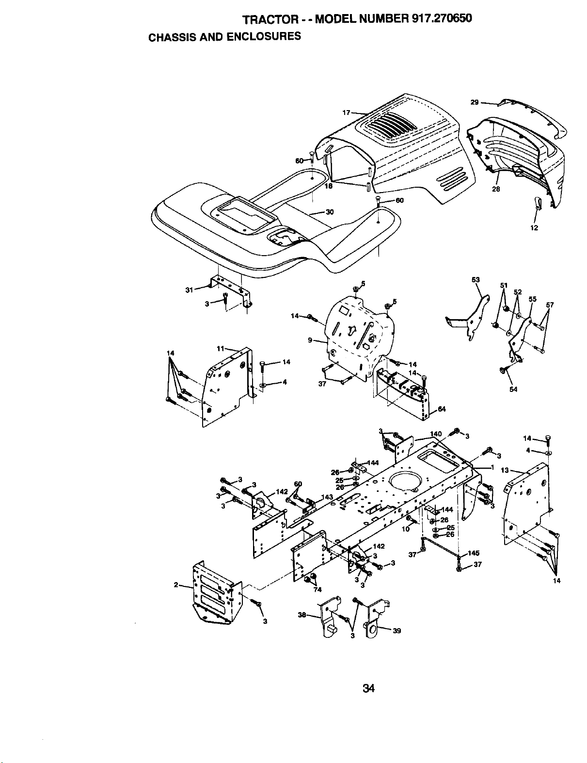
TRACTOR - - MODEL NUMBER 917.270650
CHASSIS AND ENCLOSURES
28
12
31
3
3
74
34
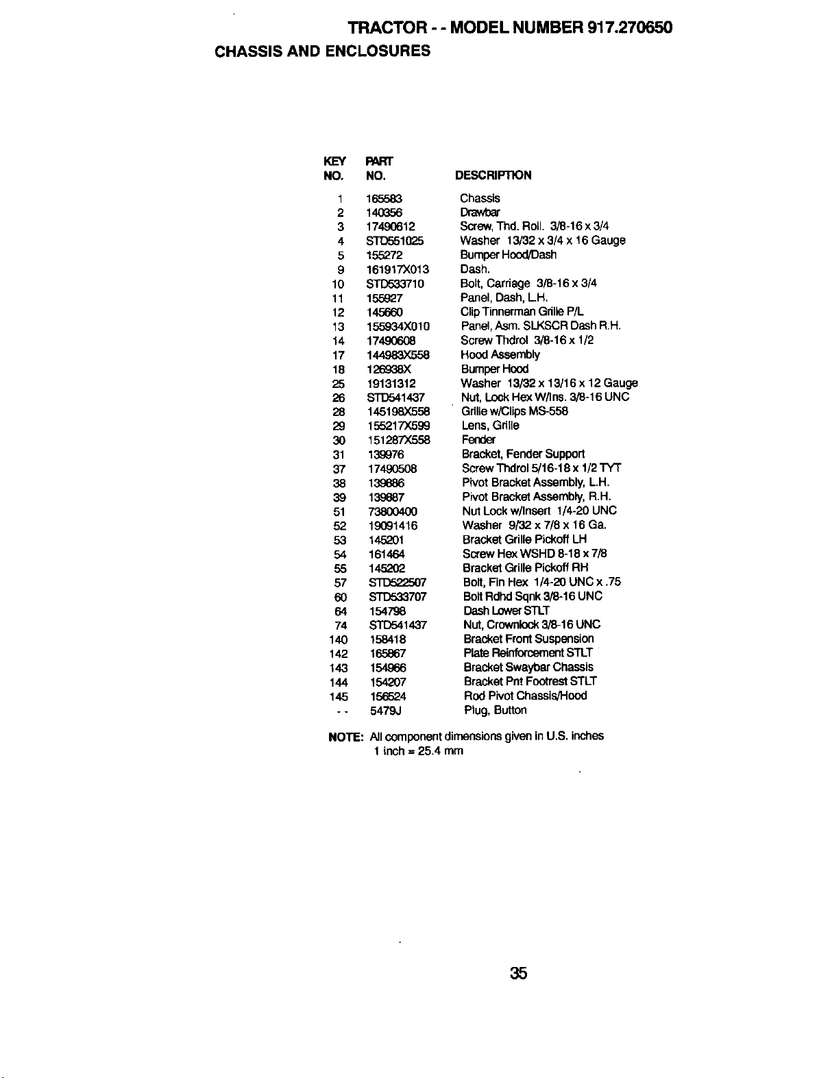
TRACTOR - - MODEL NUMBER 917.270650
CHASSIS AND ENCLOSURES
KEY PART
NO. NO. DESCRIPTION
1 165583 Chassis
2 140G56 Drawbar
3 17490612 Screw,Thd. Roll. 3/8-16 x3/4
4 _10_5 Washer 13/32 x 3/4 x 16 Gauge
5 155272 Bumper Hood/Dash
9 161917X013 Dash.
10 STD533710 Bolt, Carriage 3/8-16 x 3/4
11 155927 Panel, Dash, LH.
12 145660 Clip Tinnerman Gdlle P/L
13 155934X010 Panel,Asm. SLKSCR Dash RH.
14 1749(To08 Screw Thdrol 3/8-16 x 1/2
17 144983X558 HoodAssembly
18 126938)( BumperHcod
25 19131312 Washer 13/32 x 13/16 x 12 Gauge
26 STD541437 Nut,LockHexW/Ins. 3/B-16 UNC
28 145198X558 GrillawK_lipsMS-558
29 155217X599 Lens, Gdlle
30 151287X558 Fender
31 139976 Bracket, FenderSupport
37 174,90508 Screw Thdrol5/16-18 x 1/2 TYT
38 139686 PivotBracketAssembly,LH.
39 139887 PivotBracketAseembly,R.H.
51 73800400 NutLockw/Insert 1/4-20 UNC
52 19091416 Washer 9/32 x 7/8 x 16 Ga.
53 145201 Bracket Grille PickoffLH
54 161464 Screw Hex WSHD 8-18 x 7/3
55 145202 Bracket Grille Pickoff RH
57 s'rD522507 Bolt, Fin Hex 1/4-20 UNCx .75
60 S'rD533707 BoltRdhdSqnk3/8-16 UNC
64 154798 DashLowerSTLT
74 STETo41437 Nut,Crownlock 3/8-16 UNC
140 158418 BracketFrootSuspansion
142 165867 PlateReinforcementSTLT
143 154966 BracketSwaybar Chassis
144 154207 Bracket POtFootrestSTLT
145 156524 Rod PivotChassis/Hood
- - 5479J Plug, Button
NOTE:
Allcomponentdimensions giveninU.S. inches
1 inch = 25.4 mm
35
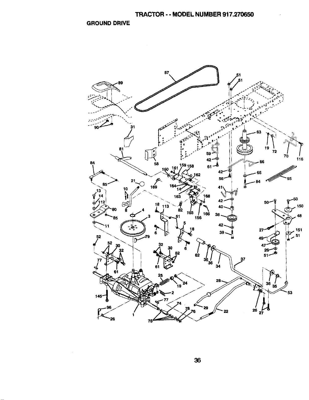
TRACTOR - - MODEL NUMBER 917.270650
GROUND DRIVE
57
25
56
72
116
_T-_F F _""_8
26 27
36
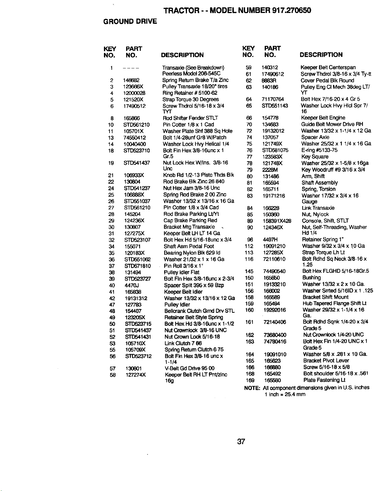
TRACTOR - - MODEL NUMBER 917.270650
GROUND DRIVE
KL=Y PART KEY PART
NO. NO. DESCRIPTION NO. NO. DESCRIPTION
2
3
4
5
6
8
10
11
13
14
18
19
21
22
24
25
26
27
28
29
3O
31
32
34
35
36
37
38
39
4O
41
42
47
48
49
5O
51
52
53
55
56
57
58
Transaxle (See Breakdown) 59 14(_12
PeerlessModel206-545C 61 17490612
146682 Spring ReturnBrakeT/a Zinc 62 8883R
123O66X Pulley Transaxte 18/20" tires 63 140186
12000028 Ring Retainer#5100-62
121520X Strap Torque 30 Degrees 64 71170764
17490512 Screw Thdrol 5/16-18 x 3/4 65 ST[To51143
TYT
165866 RodShifterFenderSTLT 66 154778
STD561210 Pin Cotter 1[8 x 1Cad 70 134683
105701X Washer Plate Shf 388 Sq Hole 72 19132012
74550412 Bolt 1/4-26unf Gr8 W/Patch 74 137057
10040400 Washer Lock Hvy Helical 1/4 75 121749X
STD523710 Bolt Fin Hex 3/8-16unc x I 76 STD581075
Gr.5 77 123583X
STD541437 NutLockHex W/Ins. 3/8-16 78 121748X
Unc 79 2228M
106933)( Knob Rd 1/2-13 PlsteThds BIk 80 131486
130604 Rod BrakeBIk Zinc26 840 81 165594
STD541237 NutHex Jam 3/9-16 Unc 82 165711
106888)( SpdngRodBrake 2 00 Zinc 83 19171216
ST[To510_7 Washer 13/32 x 13/16 x 16 Ga
STD561219 Pin Cotter 1/8 x 3/4 Cad 84 166228
145204 Rod Brake ParkingLt/Yt 85 150360
124236)( Cap Brake Parking Red 89 158391X428
130807 Bracket MtgTransaxle . 90 124346X
127275X Keeper Belt LH LT14 Ga
STD523107 Bolt Hex Hd 5/16-18unc x 3/4 96 4497H
155071 Shaft Asm Pedal Foct 112 19091210
120183X Beadng Nylon BIk 629 Id 113 127285X
STD5510(_ Washer 21/82 x I x 16 Ga 116 72110610
STD571810 Pin Roll3/16 x 1"
131494 PulleyIdler Flat 145 7449(7340
_27 BoltFin Hex 3/8-16unc x 2-3/4 150 165850
4470J Spacer Spilt395 x 59 Bzp 151 19133210
165838 KeeperBelt Idler 156 166002
19131312 Washer 13/82 x 13/16 x 12 Ga 158 165589
127783 PulleyIdler 159 165494
154407 BeUcrankClutchGrnd DrySTL 160 19292016
123L>05X Retainer BeltStyle Spdng
STD523715 BoltHex Hd3/8-16unc x 1-1/2 161 72140406
STD541437 NutCrownlock3/8-16 UNC
STD541431 NutCrownLock5/16-18 162 73680400
105710X Unk Clutch7 66 163 74780416
105709X Spdng ReturnClutch6 75
STD523712 BoltFie Hex 3/8-16 uncx 164 19(391010
1-1/4 165 165623
130601 V-Belt Gd Drive 95 00 166 166880
127274X Keeper BeltRH LTPet/zinc 168 1654,92
16g 169 165580
NOTE:
Keeper BeltCenterspan
ScrewThdrol 3/8-16 x 3/4 Ty-tt
Cover Pedal BIkRound
PulleyEng CI Mech 38deg LT/
Y'r
BoltHex 7/16-20 x 4 Gr 5
Washer LockHvy HIclSpr 7/
16
KeeperBelt Engine
GuideBeltMowerDriveRH
Washer 13/32 x 1-1/4 x 12 Ga
SpacerAxle
Washer 25/32 x 1 1/4 x 16 Ga
E-ring#5133-75
KeySquare
Washer 25/32 x 1-5/8x 16ga
KeyWoodruff#9 3/16 x 3/4
Arm, Shift
ShaftAssembly
Spring,Torsion
Washer 17/82 x 3/4 x 16
Gauge
LinkTransaxJe
Nut, Nylock
Console, Shift, STLT
Nut, Self-Threading, Washer
Hd 1/4
Retainer Spring 1"
Washer 9/32 x 3/4 x 1.0Ga
Strap Torque Lh Lt
Bolt Rdhd Sq Neck 3/8-16 x
1.25
Bolt Hex FLGHD 5/16-18Gr.5
Bushing
Washer 13/32 x 2 x 10 Ga.
Washer Srrted 5/161Dx 1 .125
Bracket ShiftMount
Hub Tapered Flange Shift I_t
Washer 29/82 x 1-1/4 x 16
Ga.
Bolt Rdhd Sqnk 1/4-20 x 3/4
Grade 5
NutCrownlock 1/4-20UNC
Bolt He:<Fin 1/4-20 UNC x 1
Grade 5
Washer 5/8 x .281 x 19 Ga.
Bracket Pivot Lever
Screw5/16-16 x 5/8
Bolt shoulder5/16-19 x .561
Plate Fastening Lt
All componentdimensionsgiveninU.S. inches
1inch = 25.4 mm
37
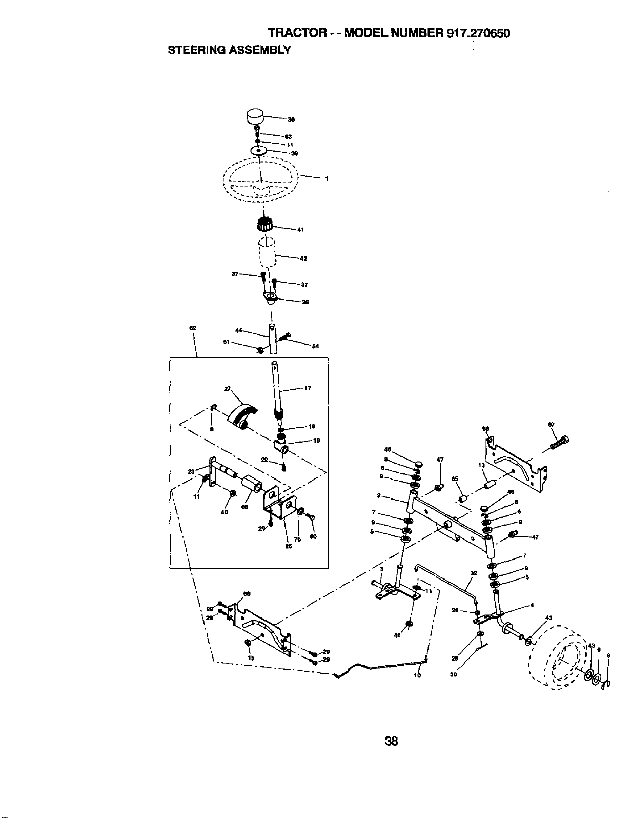
TRACTOR - - MODEL NUMBER 917.270650
STEERING ASSEMBLY
---'-_ 63
• • L J _- I I
L •
I
3O
43
38
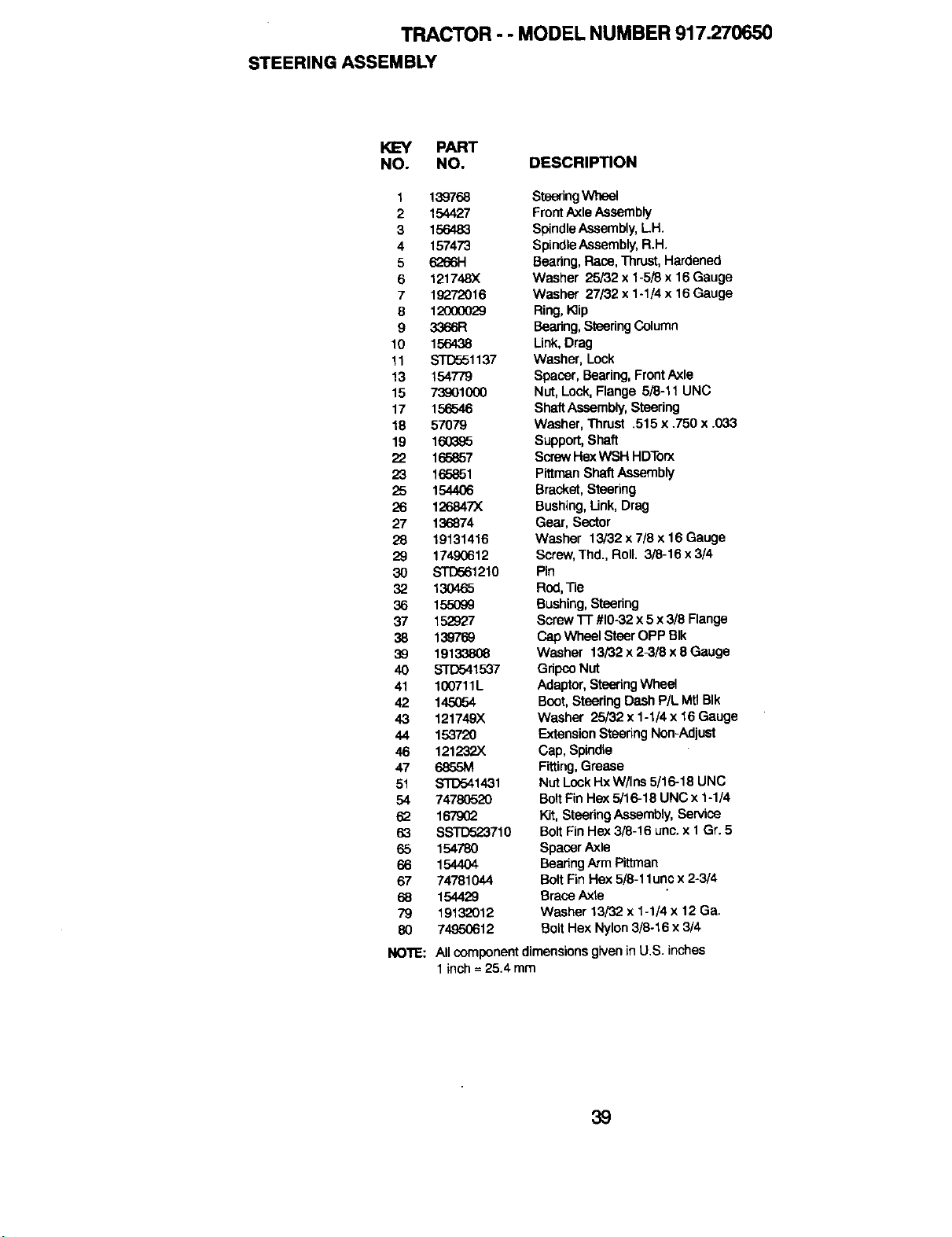
TRACTOR - - MODEL NUMBER 917.270650
STEERING ASSEMBLY
KEY PART
NO. NO. DESCRIPTION
t 139768
2 154427
3 156483
4 157473
5 626614
6 121748X
7 19272016
8 1200(x}29
9 3366R
10 156438
11 STD551137
13 154779
15 73901000
17 156546
18 57079
19 160395
22 165857
23 166861
25 164406
26 126847)(
27 136874
28 19131416
29 17490612
30 STD561210
32 13O465
36 155O99
37 152927
38 139769
39 19133806
40 _1537
41 100711L
42 145054
43 121749X
44 153720
46 121232X
47 6855M
51 STD541431
54 74780520
62 1679(_
63 SSTD523710
65 154780
66 154404
67 74781044
68 154429
79 19132012
80 74-950612
NOllE:
steering Wheel
FrontAxle Assembly
SpindleAseembly,I-H.
SpindleAssembly,R.H.
Bearing, Race, Thrust, Hardened
Washer 25/32 x 1-5/8 x 16 Gauge
Washer 27/32 x 1-1/4 x 16 Gauge
Ring, K]ip
Bearing, Steedng Column
Link, Drag
Washer, Lock
Spacer, Bearing, Front Axle
Nut, Lock, Flange 5/8-11 UNC
ShaftAssembly,Steering
Washer, Thrust .515 x .750 x .033
Support,Shaft
ScrewHexWSH HDTorx
Plttman ShaftAssembly
Bracket,Steering
Bushing,Unk, Drag
Gear, Sector
Washer 13/32 x 7/8 x 16 Gauge
Screw,Thd., Roll. 3/8-16 x3/4
Pin
Rod,Tie
Bushing,Steedng
Screw 1-1"#10-32x 5 x 3/8 Flange
Cap Wheel Steer OPP BIk
Washer 13/32 x 2-3/3 x 8 Gauge
Gdpce Nut
Adaptor,SteeringWheel
Boot,Steering DashP/L MtlBIk
Washer 25/32 x 1-1/4 x 16Gauge
ExtensionSteering Non-Adjust
Cap, Spindle
Fitting,Grease
Nut LookHx W/Ins 5/16-18 UNC
BoltFinHex 5/16-18 UNC x 1-1/4
Kit, steedng Assembly, Service
Bolt Fin Hex 3/8-16 unc. x 1Gr. 5
Spacer Axle
Bearing Arm Pittman
Bolt Fin Hex 5/8-11uric x 2-3/4
Brace Axle
Washer 13/32 x 1-1/4 x 12 Ga.
BoltHex Nylon3/8-16 x 3/4
All component dimensionsgiven inU.S. inches
1 inch = 25.4 mm
39
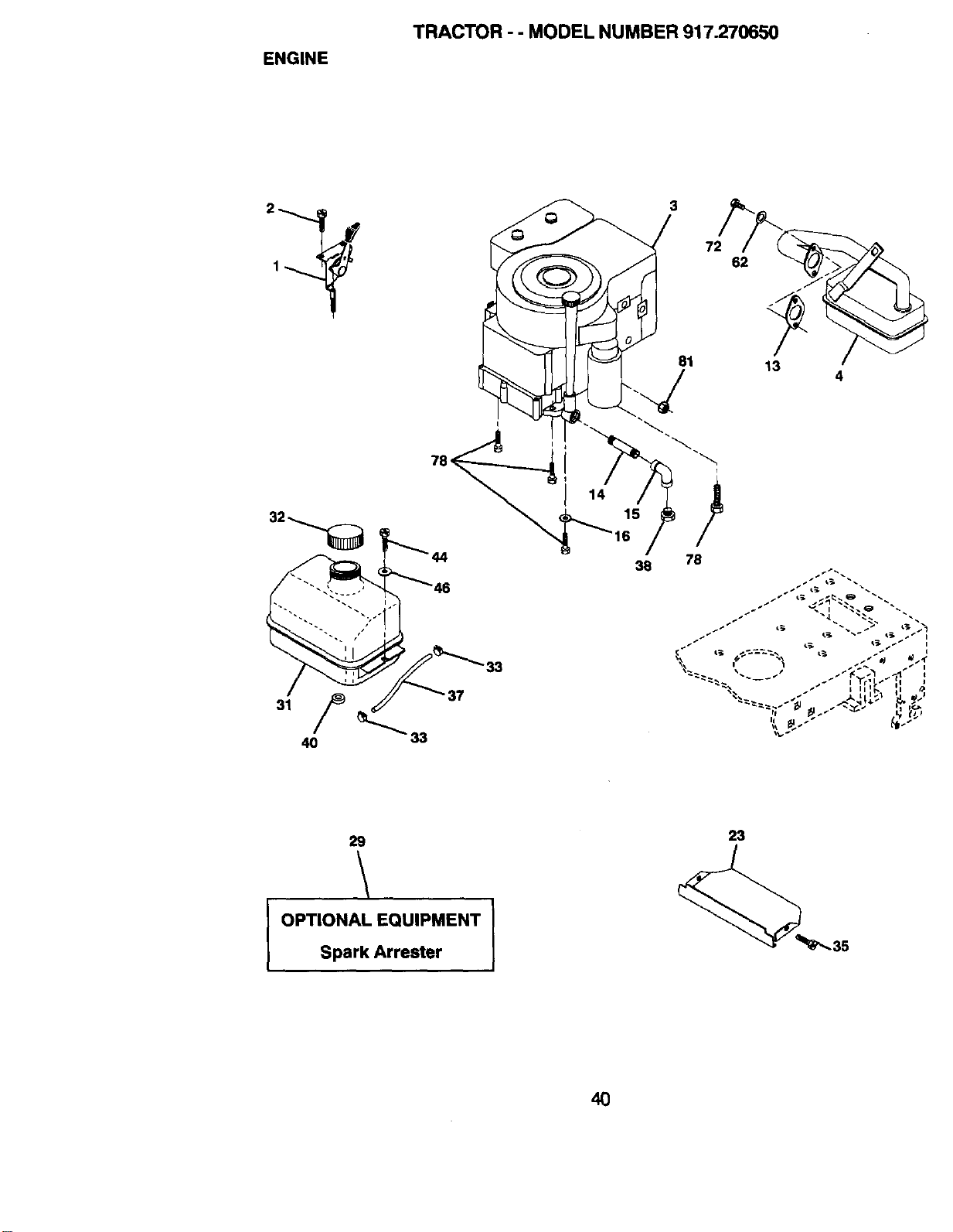
ENGINE
TRACTOR - - MODEL NUMBER 917.270650
2
1
3
81
38 78
72
62
13
4
_1 _ J, _ _ _
.J I tl,.. _a
29
\
I OPTIONAL EQUIPMENT
Spark Arrester
23
4O
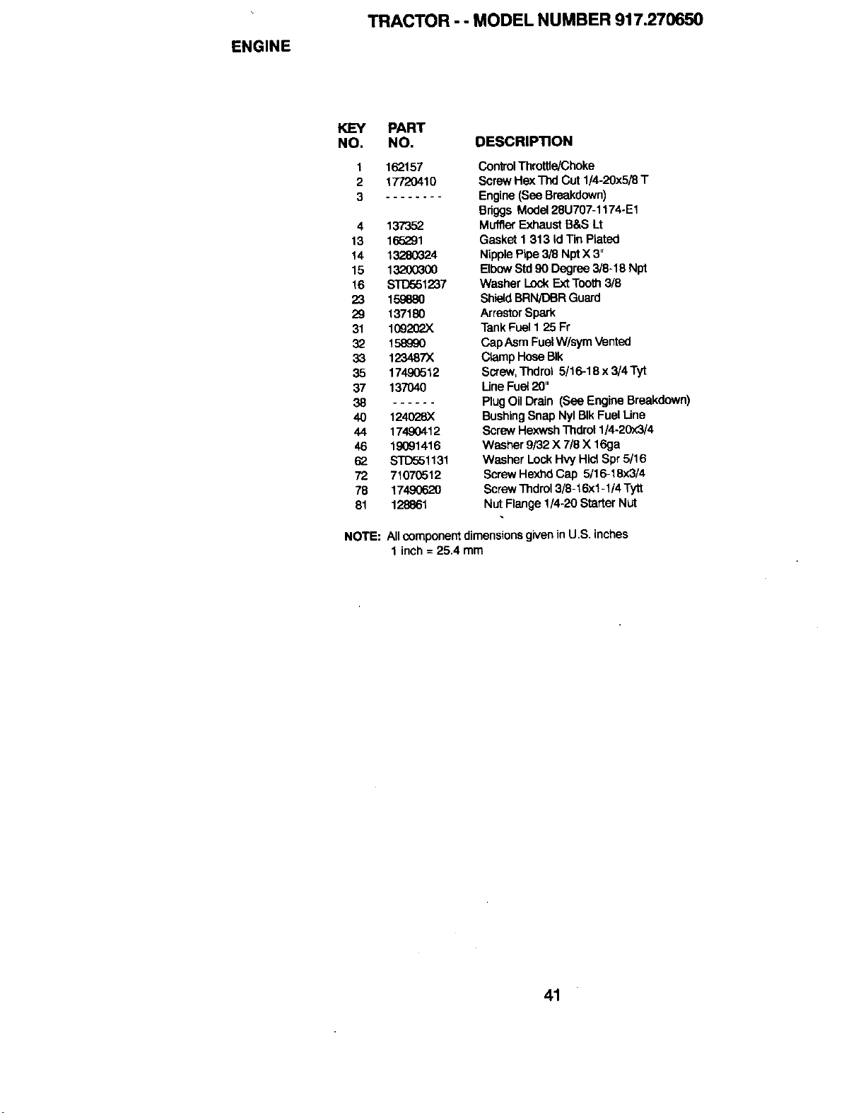
ENGINE
TRACTOR -- MODEL NUMBER 917.270650
KEY PART
NO. NO. DESCRIPTION
1 162157
2 17720410
3 ........
4 137352
13 165291
14 13280324
15 132003(X)
16 STD551237
23 159880
29 137180
31 10920P-X
32 158990
33 123487X
35 17490512
37 137040
38
40 124028)(
44 17490412
46 19091416
6;2 STD551131
72 71070512
78 17490620
81 128861
ControlThrottle/Choke
ScrewHe)(_ Cut 1/4-20x5/3 T
Engine(See Breakdown)
Bdggs Model28U707-1174-E1
MufflerExhaust B&S Lt
Gasket 1 313 IdTin Plated
NipplePipe 3/8 NptX 3"
ElbowStd 90 Degree 3/6-18 Npt
Washer LockExt Tooth3/8
ShieldBRN/DBR Guard
ArrestorSpark
TankFuel1 25 Fr
CapAsmFuel W/symVented
ClampHose BIk
Screw,Thdrol 5/16-18 x 3/4 Tyt
Une Fuel20"
Plug OilDrain (See EngineBreakdown)
BushingSnap Nyl BIk FuelLine
ScrewHexwshThdml 1/4-20x3/4
Washer 9/32 X 7/8 X 16ga
Washer LockHW HlctSpr 5/16
ScrewHexhd Cap 5/16-18x3/4
ScrewThdml 3/8-t 6x1-1/4 Tytt
Nut Flange1/4-20 StarterNut
NOTE: All componentdimensionsgiven in U.S, inches
1 inch = 25.4 mm
41
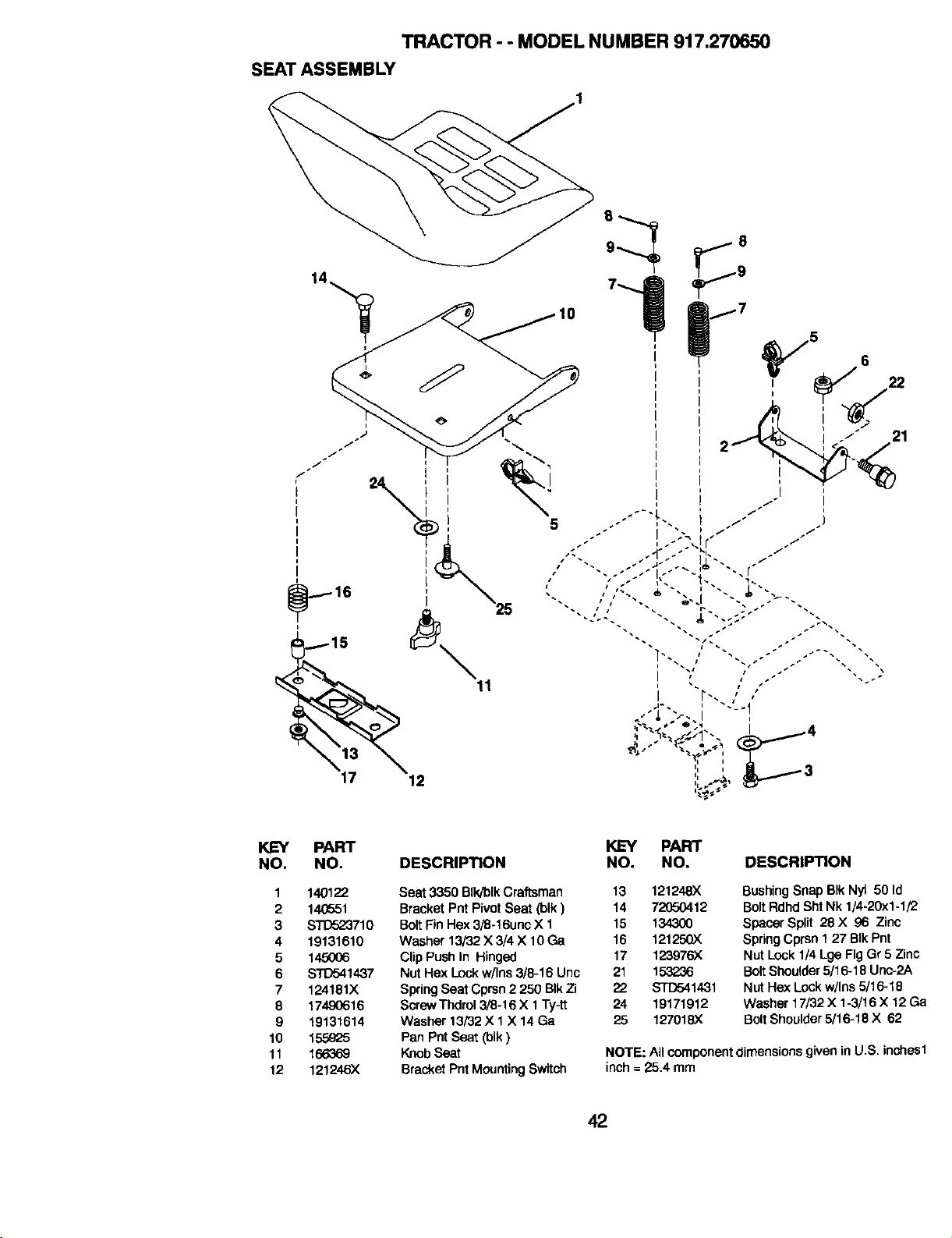
TRACTOR - - MODEL NUMBER 917.270650
SEATASSEMBLY
12
NO.
1
2
3
4
5
6
7
8
9
10
11
12
PART KEY PART
NO. DESCRIPTION NO. NO. DESCRIPTION
140122
14(T_51
_710
19131610
145OO6
S_1437
124181X
17490616
19131614
155_Z5
166369
121246X
Seat 3350 BIk/blkCraftsman 13 121248X
Bracket Pnt PivotSeat (blk) 14 72_o0412
BoltFinHex 3/8-16unc X t 15 134300
Washer 13/32 X 3/4 X 10 Ga 16 121250X
Clip Push In Hinged 17 123976X
Nut Hex Lockw/Ins 3/8-16 Unc 21 153236
SpringSeat Cprsn2 250 BIkZi 22 STD541431
ScrewThdrol3/8-16 X 1Ty-_ 24 19171912
Washer 13/32 X 1 X 14 Ga 25 127018X
Pan PntSeat (blk)
KnobSeat
Bracket Pnt MountingSwitch
BushingSnap BIk Nyt 50 Id
BoltRdhd Sht Nk 1/4-20x1-1/2
Spacer Split 28 X 96 Zinc
SpringCprsn 127 BIkPnt
Nut Lock1/4 Lge Fig Gr 5 Zinc
BoltShoulder5/16-18 Unc-2A
Nut Hex Lockw/Ins 5/16-18
Washer 17/32 X 1-3/16 X 12 Ga
BoltShoulder5/16-18 X 62
NOTE: All componentdimensionsgivenin U.S inches1
inch= 25.4 mm
42
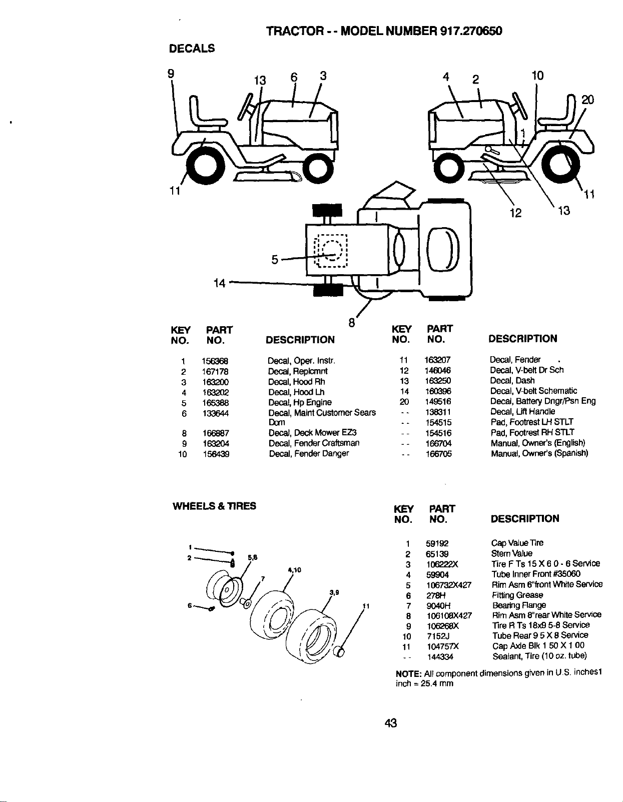
DECALS
9
TRACTOR - - MODEL NUMBER 917.270650
13 6 3 4 2
10
2O
11
12
13
14
KEY
NO.
1
2
3
4
5
6
8
9
10
PART
NO.
156368
167178
16320O
163262
165388
133644
166887
1632O4
156439
K3EY PART
DESCRIPTION NO. NO.
Decal, Oper. Instr. 11 163207
DecaJ,Replcmnt 12 146046
Decal,Hood Rh 13 163250
Decal,Hood Lh 14 160396
Decal,Hp Engine 20 14,9516
Decal, MaintCustomer Sears - - 138311
Dora - - 154515
Deca_,Deck Mower EZ3 - - 154516
Decal, FenderCraftsman - - 166704
Decal, FenderDanger +- 166705
DESCRIPTION
Decal, Fender .
Decal, V-belt Dr Sch
Decal, Dash
Decal, V-belt Schematic
Decal, Battery Dngr/Psn Eng
Decal, Lift Handle
Pad, Footrest LH STLT
Pad, Footrest RHSTLT
Manual, Owner's (English)
Manual,Owner's (Spanish)
WHEELS & TIRES
11
PART
NO. NO. DESCRIPTION
1
2
3
4
5
6
7
8
9
10
11
59192
65139
106222X
59904
106732X427
2781-1
9040H
106108X427
106268X
7152J
104757X
144334
CapValue1ire
StemValue
Tire F Ts 15 X 6 0 - 6 Service
Tube Inner Front#35060
RimAsm 6"frontWhite Service
Fitting Grease
BearingRange
RimAsm8"rear WhiteService
Tire R "Is 18)<95-8 Service
Tube Rear9 5 X 8 Service
Cap Axle BIk 150 X t 00
Sealant, Tire (10 oz.tube)
NOTE: All component dimensionsgiven in U.S. inches1
inch = 25.4 mm
43
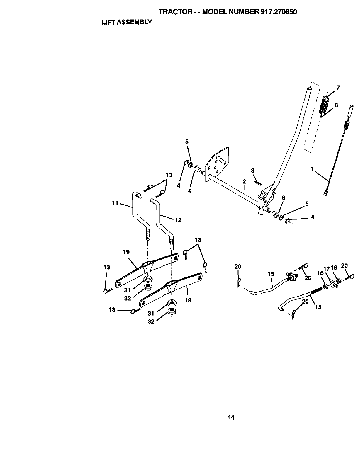
TRACTOR - - MODEL NUMBER 917.270650
LIFT ASSEMBLY
7
5
2
20
3
15
20
44

TRACTOR - - MODEL NUMBER 917.270650
LIFT ASSEMBLY
KEY PART
NO. NO, DESCRIPTION
1 159460 WasherAsm InnerSpringW/Plunger
2 159471 ShaftAsm, LiftRH
3 105767X PinGroove
4 12(300002 ERing #5133_o2
5 19211621 Washer 21/32 x 1x 21 Ga.
6 120183X BearingNylong
7 125631X GripHandleFluted
8 122365X ButtonPlungerRead
11 139665 Unk Asm Lift LH.
12 139866 Unk Asm Lift R.H.
13 S'TD624008 RetainerSpring
15 127218 Unk Front
16 73350800 Nut Jam Hex 1/2-13 Une
17 130171 TrunnionI_k Zinc
18 73680800 Nut Crownlock1/2-13 Unc
19 139868 ArmSuspensionMower
20 163552 RetainerSpring
31 1403(_ Bearing, Pvt.Lift.Spherical
32 73540600 NutCr'ownlock 3/8-24
NOTE: AJIcomponentdimensionsgiveninU.S. inches
1 inch = 25.4 mm
45
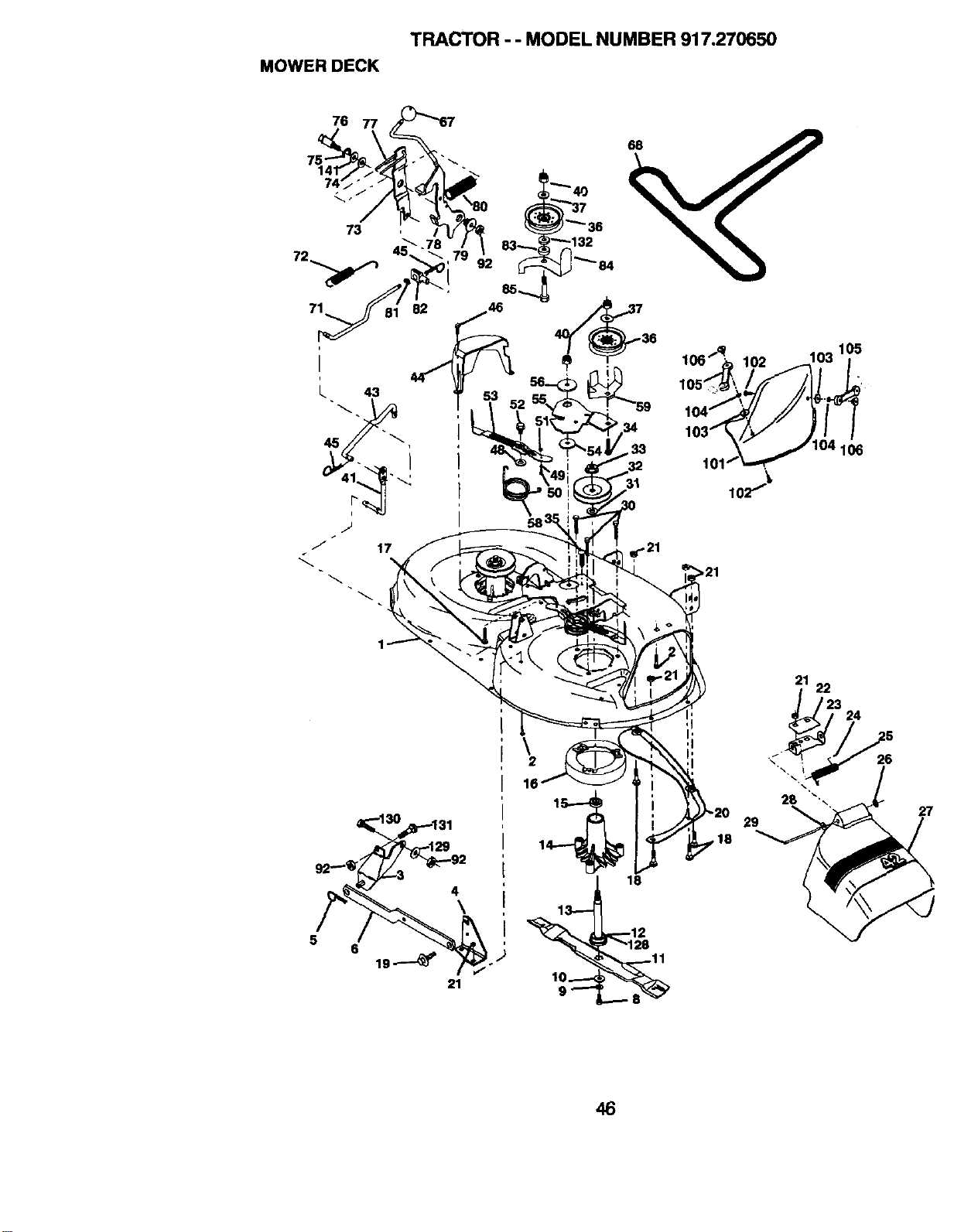
MOWER DECK
TRACTOR - - MODEL NUMBER 917.270650
76
) 132
_ "''" 84
32
31
21
22
5
6
4
\
26
27
46
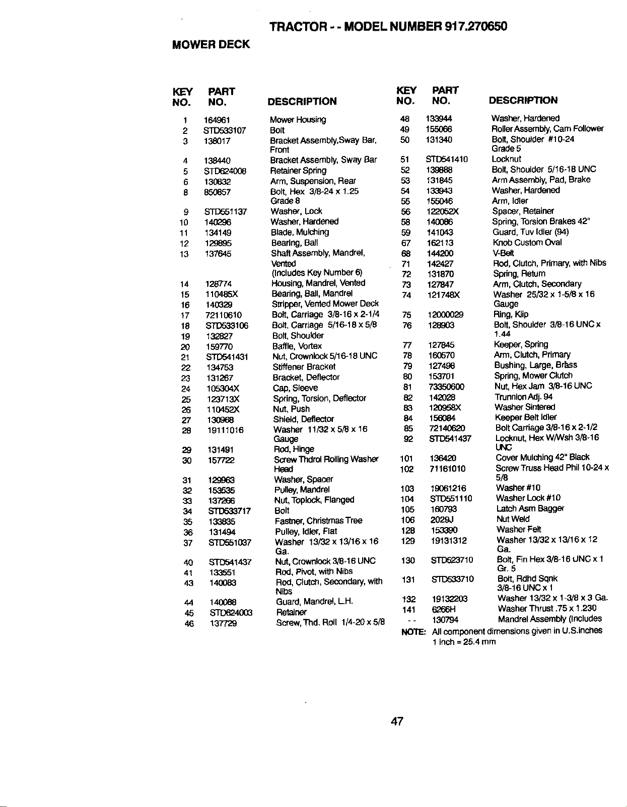
MOWER DECK
TRACTOR - - MODEL NUMBER 917.270650
KEY PART
NO. NO.
1 164861
2 STD533107
3 138017
4 138440
5 STD624008
6 13_632
8 85O857
9 STO551137
10 140296
11 134149
12 129895
13 137645
14 126774
15 110485)(
16 14(]G29
t7 7211Q610
18 _1(]6
19 132827
20 159770
21 STD541431
_:_ 134753
23 131267
24 105304X
26 123713)(
26 110452X
27 130968
28 19111016
2_ 131491
3O 157722
31 1;29963
32 153535
33 1_
34 _717
35 133835
36 131494
37 STD551037
40 BTD541_7
41 133551
43 14OO83
44 140088
45 STD624003
46 137729
KEY PART
DESCRIPTION NO. NO. DESCRIPllON
Mower Housing 48 133944 Washer,Hardened
Boff 49 155066 RollerAssemb!y,Cam Follower
Bracket Assembly,Sway Bar, 50 131340 Bolt, Shoulder #10_24
Front Grade5
BracketAssembly, Sway Bar 51 STD541410 Locknut
RetainerSpdng 52 139888 Bolt,Shoulder 5/16.18 UNC
Arm, Suspension,Rear 53 131845 ArmAssembly, Pad, Brake
Bolt, Hex 3/8-24 x 1.25 54 133943 Washer, Hardened
Grade 8 55 155046 Arm, Idler
Washer, Lock 56 122052X Spacer, Retainer
Washer, Hardened 58 140086 Spring,TorsionBrakes 42"
Blade,Mulching 59 141[H-3 Guard, Tuv IdJer(94)
Bearing,Ball 67 162113 KnobCustomOval
ShaftAssembly,Mandrel, 68 144200 V-Belt
Vented 71 142427 Rod,Clutch, Pdmary,with Nibs
(Includes Key Number 6) 72 131870 Spring,Return
Housing,Mandrel,Vented 73 127847 Arm, Clutch,Secondary
Bearing,Ball,Mandrel 74 121748)( Washer 25/32 x 1-5/3 x 16
Stripper,Vented Mower Deck Gauge
Bolt, Carriage 3/8-16 x 2-1/4 75 t_ F_ng,K(ip
Bolt, Cardage 5/16-16x5f8 76 128903 Bolt,Shoulder 3/3-16UNCx
Bolt,Shoulder 1.44
Baffle, Vortex 77 127845 Keeper, SDdng
Nut, CrownlOCk5/16-18 UNC 78 160570 Arm, Clutch, Primary
StiffenerBracket 79 1274.g6 Bushing, Large, Brass
Bracket, Deflector 80 153701 Spring,MowerClutch
Cap, Sleeve 81 73350600 Nut,HexJam 3/8-16 UNC
Spring,Torsion, Deflector 82 142028 TrunnionAdj. 94
Nut, Push 83 120958X Washer Sintered
Shield,Deflector 84 156084 Keeper Belt /dler
Washer 11/32 x 5/8 x 16 85 72140620 BoltCardage 3/8.16 x 2.1/2
Gauge 92 STD541437 Lo_,mut,Hex W/Wsh 3/8-16
Rod,Hinge UNC
ScrewThdrolRoilingWasher 101 136420 CoverMulching42"Black
Head 102 71161010 ScrewTruasHead Phil10-24 x
Washer, Spacer 5/8
Pulley,Mandrel 103 19061216 Washer#10
Nut,Top.ok, Flanged 104 STD551110 WasherLock#10
Bolt 105 160793 LatchAsm Bagger
Fastner,Christmas Tree 106 2029J NutWeld
Pulley,Idler,Flat 128 !.533_0 Washer Felt
Washer 13/'32x 13/16 x 16 129 19131312 Washer 13/32 x 13/16 x 12
Ga. Ga.
Nut.Crownlcek3/8-16 UNC 130 STD523710 Bolt, Fin Hex 3/8-16 UNC x 1
Rod, Pivot,wi_ Nibs Gr.5
Rod,Clutch,Secondary,with 131 STD533710 Bert, RdhdSqnk
Nibs 3/8-16 UNC x 1
Guard,Mandrel, LH. 132 1913,_'03 Washer 13/32 x 1-3/3 x 3 Ga.
Retainer 141 6266H Washer Thrust.75 x 1.230
Screw,Thd. Roll 1/4-20 x 5/3 - - 130794 MandrelAssembly(Includes
NOTE: PJleomponentd_menslonsgk,eninU.S.inches
1inch =26.4 mm
47
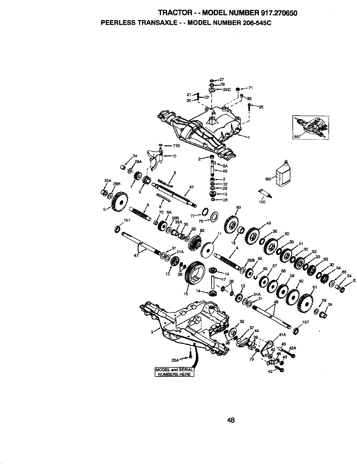
TRACTOR - - MODEL NUMBER 917.270650
PEERLESS TRANSAXLE - - MODEL NUMBER 206-545C
35A
157
8
70 6A
82
11
150
47
13
29
157
41A
NUMBERS HERE
48
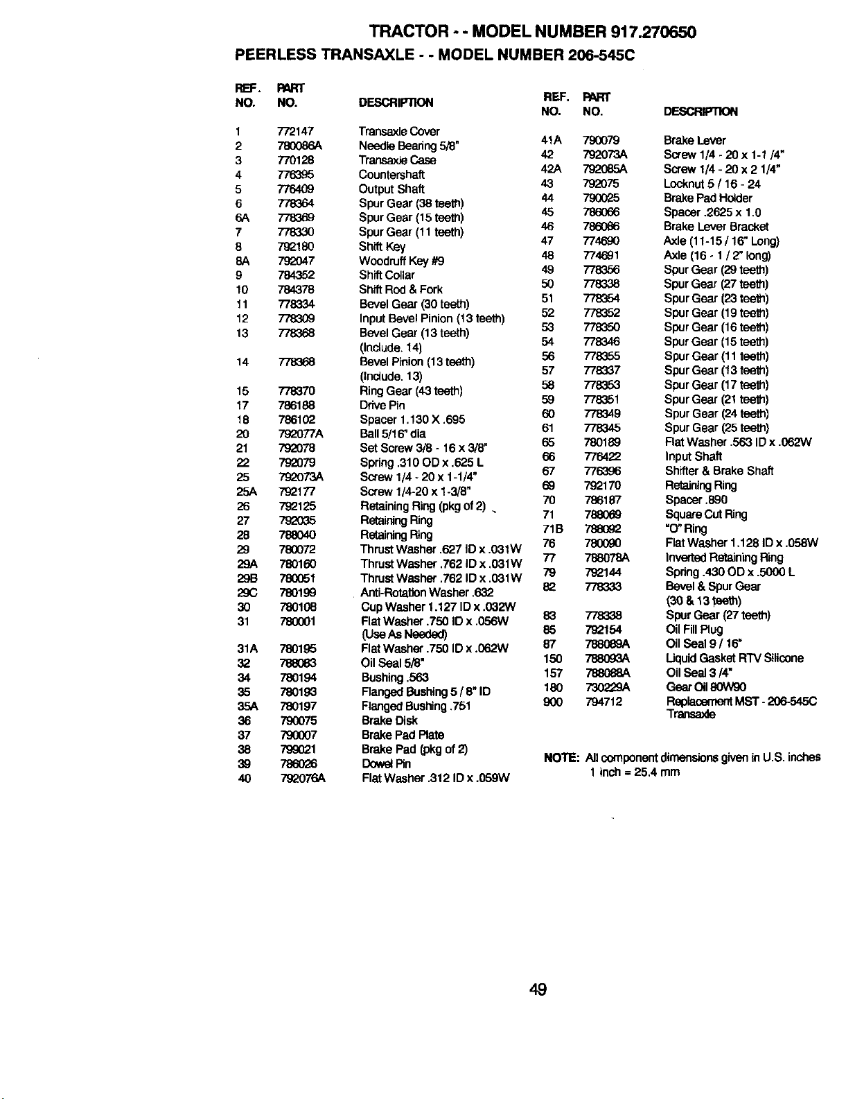
TRACTOR - - MODEL NUMBER 917.270650
PEERLESS TRANSAXLE - - MODEL NUMBER 206-545C
RB:. PART
NO. NO. DESCRIPTION
1 772147
2 780086A
3 770128
4
5 776409
6 778364
6A 778369
7 778330
8 79_180
8A 792047
9 784352
10 784378
11 778334
12 778309
13 778368
14 778368
15 77837O
17 786188
18 786102
20 792077A
21 792078
22 792079
25 7o_073A
25A 79_177
26 79_125
27 792035
28 78804O
29 780072
29A 780160
29B 780051
29C 780199
30 780108
31 780O01
31A 78O195
32 788083
34 780194
35 780193
35A 780197
36 790075
37 790007
38 799(_1
39 786O26
4O 792076A
REF. PART
NO. NO.
Transaxle Cover
Needle Bearing5/B" 41A 790079
TransaxleCase 42 792073A
Countersha_ 42A 792085A
OutputShaft 43 792075
Spur Gear (38 teeth) 44 790(325
Spur Gear (15teeth) 45 786066
Spur Gear (11teeth) 46 786086
Shift Key 47 774690
Woodruff Key#9 48 774691
Shift Collar 49 778356
ShiftRod & Fork 50 778338
Bevel Gear (30teeth) 51 778354
InputBevel Pinion (13 teeth) 52 778352
Bevel Gear (13teeth) 53 778350
(Inclode. 14) 54 778346
Bevel Pinion(13 teeth) 56 778355
(Include.13) 57 778337
Ring Gear (43teeth) 58 778353
Drive Pin 59 778351
Spacer 1.130 X .695 60 778349
Ball5/16" dia 61 778345
Set Screw3/8 - 16 x 3/8" 65 780189
Spring.310 OD x .625 L 66 776422
Screw 1/4 * 20 x 1-1/4" 67 776396
Screw 1/4-20 x 1-3/8" 69 792170
Retaining Ring (pkgof2) . 70 786187
RetainingRing 71 7880_9
RetainingRing 71B 788092
ThrustWasher .627 ID x .031W 76 780090
ThrustWasher .762 IDx .031W 77 788078A
ThrustWasher .762 ID x .031W 79 792144
Anti-RotationWasher .632 82 778333
CupWasher 1,127 ID x.032W
FlatWasher .750 ID x .056W 83 778338
(UseAsNeeded) 85 792154
FlatWasher .750 ID x .062W 87 788069A
Oil Seal 5/6" 150 788093A
Bushing .563 157 788088A
FlangedBushing5/ 8" ID 180 730229A
Ranged Bushing.751 900 794712
Brake Disk
Brake Pad Rate
Brake Pad (pkgof2)
DowelPin
Flat Washer .312 IDx .059W
DESCRIPTION
Brake Lever
Screw 1/4 -20 x 1-1/4"
Screw 1/4- 20 x 2 1/4"
Locknut5 / 16 - 24
Brake Pad Holder
Spacer .2625 x 1.0
Brake Lever Bracket
Axle (11-15 / ! 6" Long)
Axle (16 - 1/ 2" long)
Spur Gear (29teeth)
Spur Gear (27teeth)
Spur Gear (23 teeth)
Spur Gear (19 teeth)
Spur Gear (16 teeth)
Spur Gear (15 teeth)
Spur Gear (11 teeth)
Spur Gear (13 teeth)
Spur Gear (17 teeth)
Spur Gear (21 tee_)
Spur Gear (24teeth)
Spur Gear (25teeth)
Rat Washer .563 ID x .062W
Input Shaft
Shifter & Brake Shaft
RetainingRing
Spacer ,890
SquareCutRing
=O"Ring
Flat Washer 1.128 ID x .058W
InvertedRetUrningRing
Spring .430 OD x .5000 L
Bevel & Spur Gear
(30 & 13 tee_)
Spur Gear (27 teeth)
Oil FillPlug
Oil Seal 9 / 16"
Uquid GasketRTV Silicone
OilSeal 3/4"
Geer Oil80W90
Replacemeet MST -206-54SC
Trensaxle
NOTE: All componentdimensio_ givenin U.S. inches
1 inch =25.4 mm
49
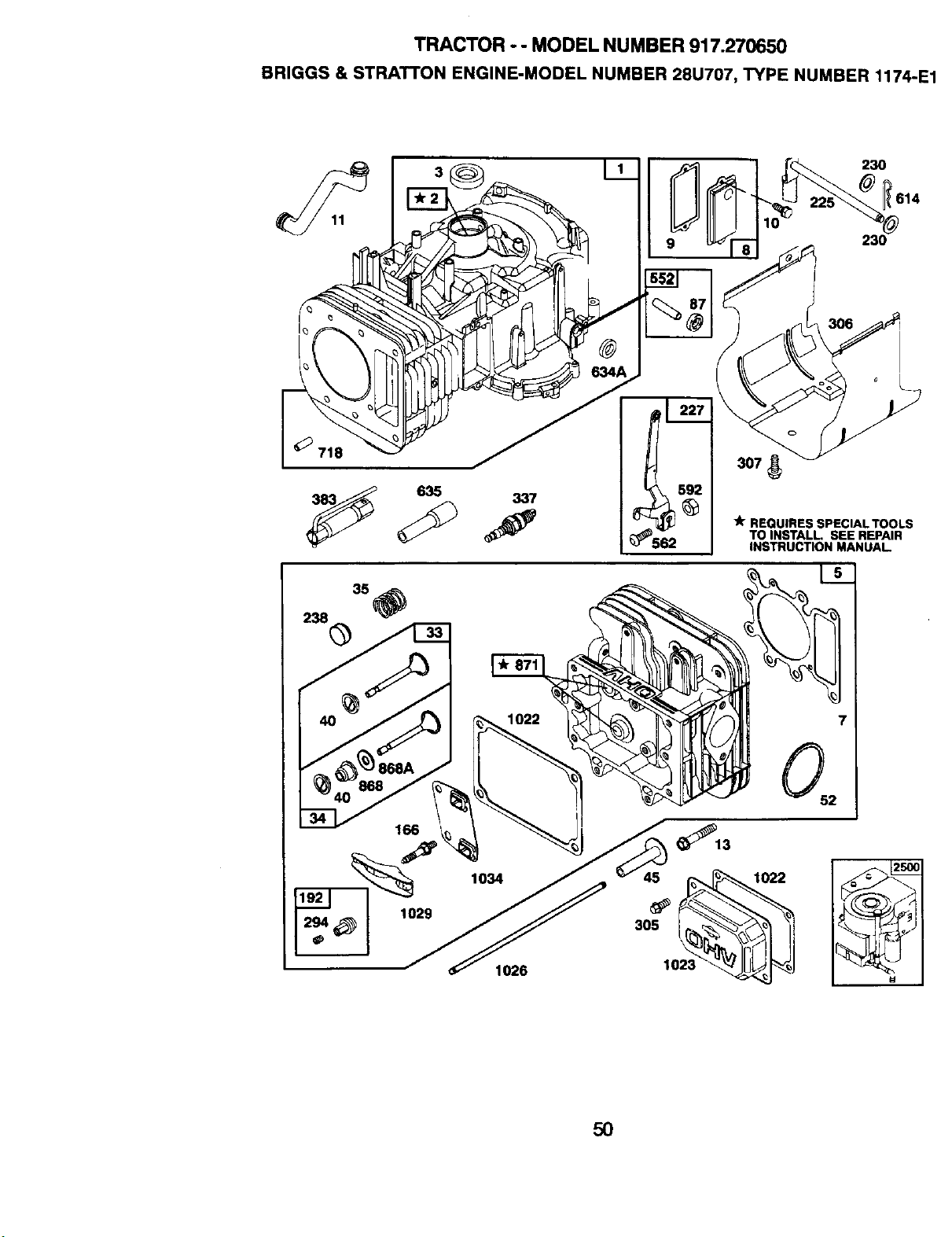
TRACTOR - - MODEL NUMBER 917.270650
BRIGGS & STRAI-rON ENGINE-MODEL NUMBER 28U707, TYPE NUMBER 1174-E1
230
614
230
I_ REQUIRES SPECIALTOOLS
TO INSTALL. SEE REPAIR
INSTRUCTION MANUAL
1034
1026
5O
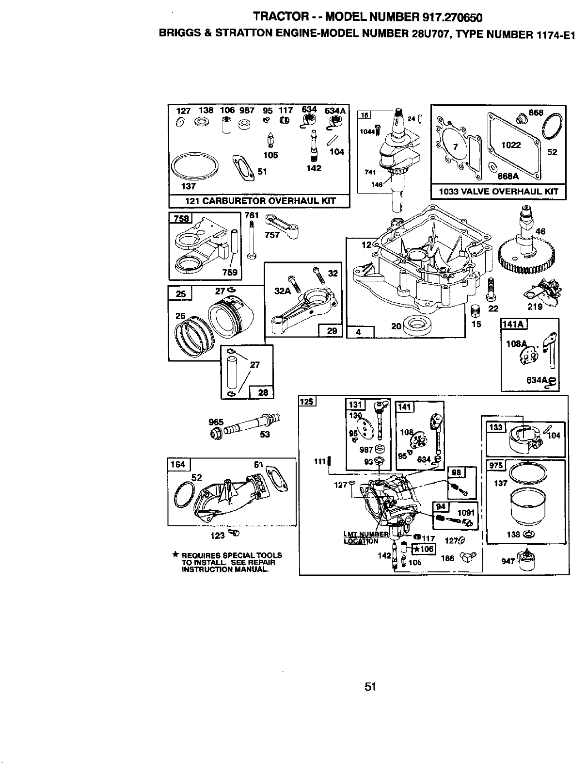
TRACTOR - - MODEL NUMBER 917.270650
BRIGGS & STRA'I'I'ON ENGINE-MODEL NUMBER 28U707, TYPE NUMBER 1174-E1
127 138 106 987 95 117 634 634A
_._ 51 142
137
121 CARBURETOR OVERHAUL KIT
51 27 _
27
4r REQUIRES SPECIALTOOLS
TO INSTALL. SEE REPAIR
INSTRUCTION MANUAL.
I,o,,Y_.\
,---I 2o_
142
987_
52
1033 VALVE OVERHAUL KIT
22
15 141_.2_
634A_
13s
947_
51
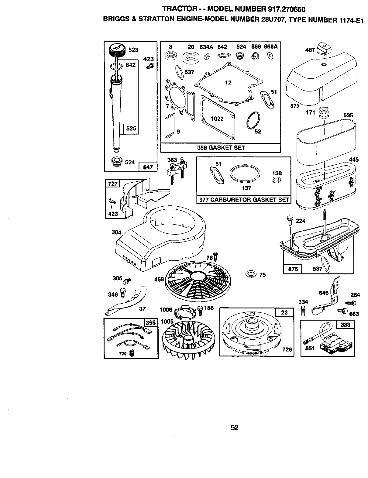
TRACTOR - - MODEL NUMBER 917.270650
BRIGGS & STRATTON ENGINE-MODEL NUMBER 28U707, TYPE NUMBER 1174-E1
523
423
842
I 525
_524
3
537
9
20 634A 842 524 868 868A
358 GASKET SET
51
137
977 CARBURETOR GASKET SET
4671
171 _ 535
445
304
305_p 468
_) 75
646_ 284
334
52
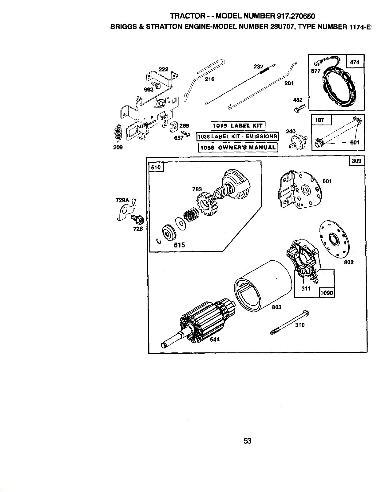
TRACTOR - - MODEL NUMBER 917.270650
BRIGGS & STRATI'ON ENGINE-MODEL NUMBER 28U707, TYPE NUMBER 1174-E
2O9
1019 LABEL KITI
11036 LABEL KIT- EMISSIONS I
11o5.ow.,s.A..A,I
729A
728
783
615
544
201
801
802
803
5,3
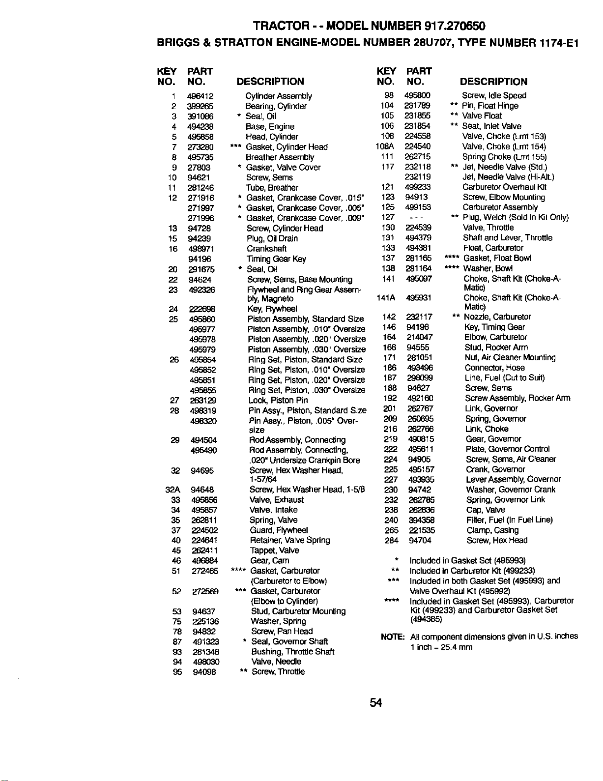
TRACTOR - - MODEL NUMBER 917.270650
BRIGGS & STRATrON ENGINE-MODEL NUMBER 28U707, TYPE NUMBER 1174-E1
KEY PART
NO. NO.
1 496412
2 399265
3 391086
4 494238
5 495858
7 273280
8 495735
9 27803
10 94621
11 281246
12 271916
271997
271996
13 94728
15 94239
16 498971
94196
20 291675
22 94624
23 492326
24 222698
25 49586O
495977
495978
495979
26 495854
495852
495851
495855
27 263129
28 4,9_]19
49832O
29
32
32A
33
34
35
37
4O
45
46
51
52
53
75
78
87
93
94
95
494504
49549O
94695
94648
495856
495857
262811
2345O2
23_1
'262411
496884
272569
94637
225136
94832
491323
281346
94068
DESCRIPTION
CylinderAssembly
Bearing, Cylinder
* Sea], Oil
Base, Engine
Head, Cylinder
*** Gasket, CylinderHead
BreatherAssembly
* Gasket, Valve Cover
Screw,Sems
Tube,Breather
* Gasket, Crankcase Cove= .015"
* Gasket, Crankcase Cover .005"
* Gasket, Crankcase Cover .009"
Screw,Cylinder Head
Plug,Oil Drain
Crankshaft
TimingGear Key
* Seal, Oil
Screw,Sems, Base Mounting
Flywheeland RingGear Assem-
bly,Magneto
Key,Rywh_l
PistonAssembly,Standard Size
PistonAssembly,.010" Oversize
PistonAssembly,.020" Oversize
PistonAssembly,.030" Oversize
RingSet, Piston,Standard Size
RingSet, Piston,.010" Oversize
RingSet, Piston,.020" Oversize
RingSet, Piston,.030" Oversize
Lock, PistonPin
PinAssy., Piston,StandardSize
PinAssy., Piston,.005" Over-
size
ROdAssembly,Connecting
RodAssembly, Connecting,
.020" Undersize Crankpin Bore
Screw, Hex Washer Head,
1-57/64
Screw,HexWasher Head, 1-5/8
Valve, Exhaust
Valve, Intake
Spring,Valve
Guard,Flywheel
Retainer,Valve Spring
Tappet,Valve
Gear, Cam
**** Gasket, Carburetor
(CarburetortoElbow)
*** Gasket, Carburetor
(Elbowto Cylinder)
Stud, CarburetorMounting
Washer, Spring
Screw,Pan Head
* Seal, Govemor Shaft
Bushing,ThrottleShaft
Valve, Needle
** Screw,Throttle
KEY PART
NO. NO. DESCRIPTION
98 495800 Screw, Idle Speed
104 231789 ** Pin,FleatHinge
105 231855 ** Valve Float
106 231854 ** Seat, InletVaive
108 234558 Valve, Choke (Lrnt153)
10BA 224540 Valve, Choke (Lrnt154)
111 262715 Spring Choke (Lint 155)
117 232118 ** Jet, Needle Valve (Std.)
232119 Jet, Needle Valve (Hi-Ait.)
121 4992"33 Carburetor Overhaul Kit
123 94913 Screw, ElbewMounting
125 4,99153 Carburetor Assembly
127 - - - ** Plug, Welch (Sold in KitOnly)
130 2345,39 Valve, Throttle
131 494379 Shaft and Lever, Throttle
133 494381 Float, Carburetor
137 281165 **** Gasket, Reat Bowl
138 281164 **** Washer, Bowl
141 495097 Choke, Shaft {'Qt(Choke-A-
MaHc)
141A 495931 Choke, Shaft Kit (Choke-A-
Matic)
142 232117 ** Nozzle, Carburetor
146 94196 Key,Timing Gear
164 214047 Elbow,Carburetor
166 94555 Stud,RockerArm
171 281051 Nut,Air CleanerMounting
186 493496 Connector,Hose
187 29_069 Line,Fuel (CUtto Suit)
188 94627 Screw,Seres
192 492160 ScrewAssembly, RockerArm
201 262767 Link,Governor
209 260695 Spring, Governor
216 262766 Link, Choke
219 490815 Gear, Governor
222 495611 Plate, GovernorControl
234 94905 Screw, Seres,AirCleaner
235 495157 Crank,Governor
227 493935 LeverAssembly,Governor
230 94742 Washer, GovemorCrank
232 262785 Spring,Govemor Unk
238 262836 Cap, Valve
240 394358 Filter,Fuel(in Fuel Une)
265 231535 Clamp,Casing
284 94704 Screw,Hex Head
* Includedin Gasket Set (495993)
** Includedin Carburetor t_t (499233)
*** Included in beth Gasket Set (495993) and
Valve Overhaul Kit (495992)
**** Included in Gasket Set (495993), Carburetor
Kit (499233) and Carburetor Gasket Set
(494385)
NOTE:
All componentdimensionsgiveninU.S. inches
1inch =25.4 mm
54
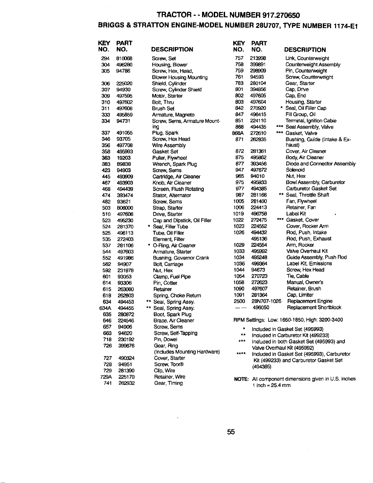
TRACTOR - - MODEL NUMBER 917.270650
BRIGGS & STRA'n'ON ENGINE-MODEL NUMBER 28U707, TYPE NUMBER 1174-E1
KEY PART
NO. NO.
294 610068
3O4 4,9628O
305 94786
3O6 225O2O
307 94930
309 4975_5
310 497602
311 497fY_
333 495859
334 94731
337 4916_5
346 93705
356 497708
358 4,95993
363 19203
383 89838
423 94903
445 49_09
467 4939O3
468 494439
474 393474
482 93621
5O3 8O60OO
510 497606
523 495230
524 281370
525 496t 13
535 272403
537 281106
544 4976O3
552 491986
562 94907
592 231978
601 930.53
614 93306
615 263080
618 262803
634 4944.53
634A 494455
635 28O872
646 224546
657 94906
663 94620
718 230192
726 39<3676
727 490324
728 94951
729 281390
729A 225170
741 262932
KEY PART
DESCRIPTION NO. NO. DESCRIPTION
Screw, Set 757 213998 Link, Counterwek:Jht
Housing, Blewer 758 399691 Counterweight Assembly
Screw, Hex, Head, 759 298_09 Pin, Counterweight
BlowerHousingMou_ng 761 94593 Screw,Counterweight
Shield,Cylinder 783 280104 Gear, Starter
Screw,Cylinder Shield 801 394856 Cap, Drive
Motor,Starter 802 497605 Cap, End
Bolt,Thru 803 497604 Housing, Starter
BrushSet 842 270920 * Seal, Oil FillerCap
Armature, Magneto 847 496415 Fill Group, Oil
Screw, Seres, Armature Mount- 851 224110 Terminal, IgnitionCable
leg 868 494435 *** Seal Aasembly, Valve
Plug, Spark 868A 272610 *** Gasket, Valve
Screw,Hex Head 871 262835 Bushing, Guide (Intake & Ex-
Wire Aseembty haust)
Gasket Set 872 281361 Cover, Air Cleaner
Puller,Flywheel 875 4,.Q586_ Body,AirCleaner
Wrench,Spark Plug 877 393456 Diodeand Connector Assembly
Screw,Seres 947 497672 Solenoid
Cartridge,AirCleaner 965 94010 Nut,Hex
Knob,AJrCleaner 975 4_a933 SowlAseambly, Carburetor
Screen, FlushRotating 977 494385 CarburetorGasketSet
Stator, Alternator 987 281166 ** Seal, ThrottleShaft
Screw, Sems 1005 281400 Fan,Flywheel
Strap, Starter 1006 224413 Retainer, Fan
Drive,Starter 1019 496758 Label Kit
Cap and Dipstick,OilFiller 1022 272475 *** Gasket, Cover
• Seal,FillerTube 1023 224552 Cover, RockerArm
Tube, OilFiller t026 494432 Rod, Push, Intake
Element, Filter 4.95136 Rod, Push, Exhaust
• O-Ring,Air Cleaner 1029 224554 Arm, Rocker
Armature,Starter 1033 495992 Valve OverhaulKit
Bushing,Governor Crank 1034 495248 GuideAssembly, PushRod
Bolt, Carriage 1036 4.99364 Label Kit, Emissions
Nut, Hex 1044 94673 Screw,Hex Head
Clamp, FuelPipe 1054 270723 Tie,Cable
Pin, Cotter 1058 272623 Manual, Owner's
Retainer 1090 497607 Retainer,Brush
Spring, Choke Return 1(91 281364 Cap, Umlter
•* Seal, Spring Assy. 2500 28N707-1026 Replacement Engine
•* Seal, Spring Assy. 496050 ReplacementShortblock
Boot, Spark Plug
Brace, Air Cleaner RPM Settings: Low: 1650-1850, High: 3200-3400
Screw, Seres * Included inGasket Set (495993)
Screw, Serf-Tapping ** IncIuded inCarburetor Kit (499233)
Pin,Dowel *** Included in beth Gasket Sat (495993) and
Gear, Ring Valve OverhaulKit(495992)
(IncludesMountingHardware) **** Includedin GasketSet (495993), Carburetor
Cover, Starter Kit (499233) and CarburetorGasket Set
Screw,Torx_ (494385)
Clip, Wire
Retainer,Wire NOTE: All component dimensions given in U.S. inches
1 inch= 25.4 mm
Gear, Timing
55

56

57

58

SUGGESTED GUIDE FOR SIGHTING SLOPES FOR SAFE OPERATION
I ""
SIGHTING
GUIDE
ONLY RIDE UP AND DOWN HILL,
NOT ACROSS HILL
_% Operate your Tractor up and down the face of slopes (not I
I
AJk greater than 15°), never across the face. Make turns gradu-
I
4_]_ ally to prevent tipping or loss of control. Exercise extreme
!1 caution when changing direction on slopes.

For in-home major brand repair service:
Call 24 hours a day, 7 days a week
1-800-4-MY-HOME sM (1-800-469-4663)
Para pedir servicio de reparacibn a domicilio
1-800-676-5811
In Canada for all your service and parts needs call
Au Canada pour tout le service ou les pi_ces
1-800-665-4455
For the repair or replacement parts you need:
Call 6 am - 11 pm CST, 7 days a week
PartsDirectsM
1-800-366-PART (1-800-366-7278)
Para ordenar piezas con entrega a domicilio
1-800-659-7084
For the location of a Sears Parts and Repair Center
in your area:
Call 24 hours a day, 7 days a week
1-800-488-1222
For information on purchasing a Sears Maintenance
Agreement or to inquire about an existing Agreement:
Call 9 am - 5 pm, Monday - Saturday
1-800-827-6655
p_
8£AR8
_q
Home Central sM
166704 Rev. 1 8.31.99 TR/JH Printed in U.S.A.


