OWNER’S MANUAL
MODELS:
LGJ & MGJ
INDUSTRIAL DUTY DOOR OPERATOR
NOT FOR RESIDENTIAL USE
Serial #
(located on electrical box cover)
Installation Date
Wiring Type
2 YEAR WARRANTY
41B6
2
7.90"
8.90"
1.97"
10.88"
1.96"
.98"
7.90"
2.25"
4.50"
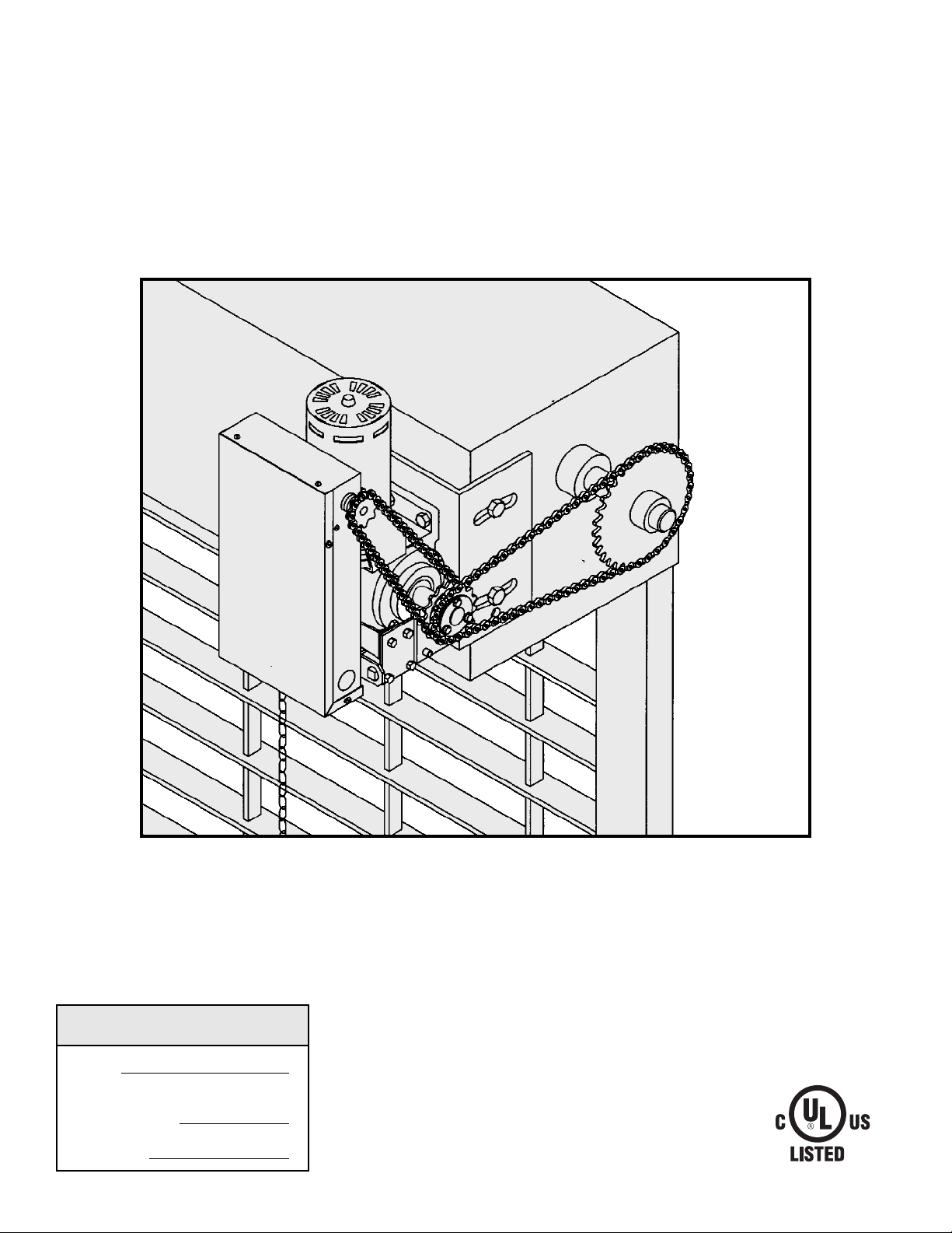
Mounting Dimensions
7.50"
7.00"
9.25"
11.05"
10.50"
11.00"
3.00" 4.75"
5.50"
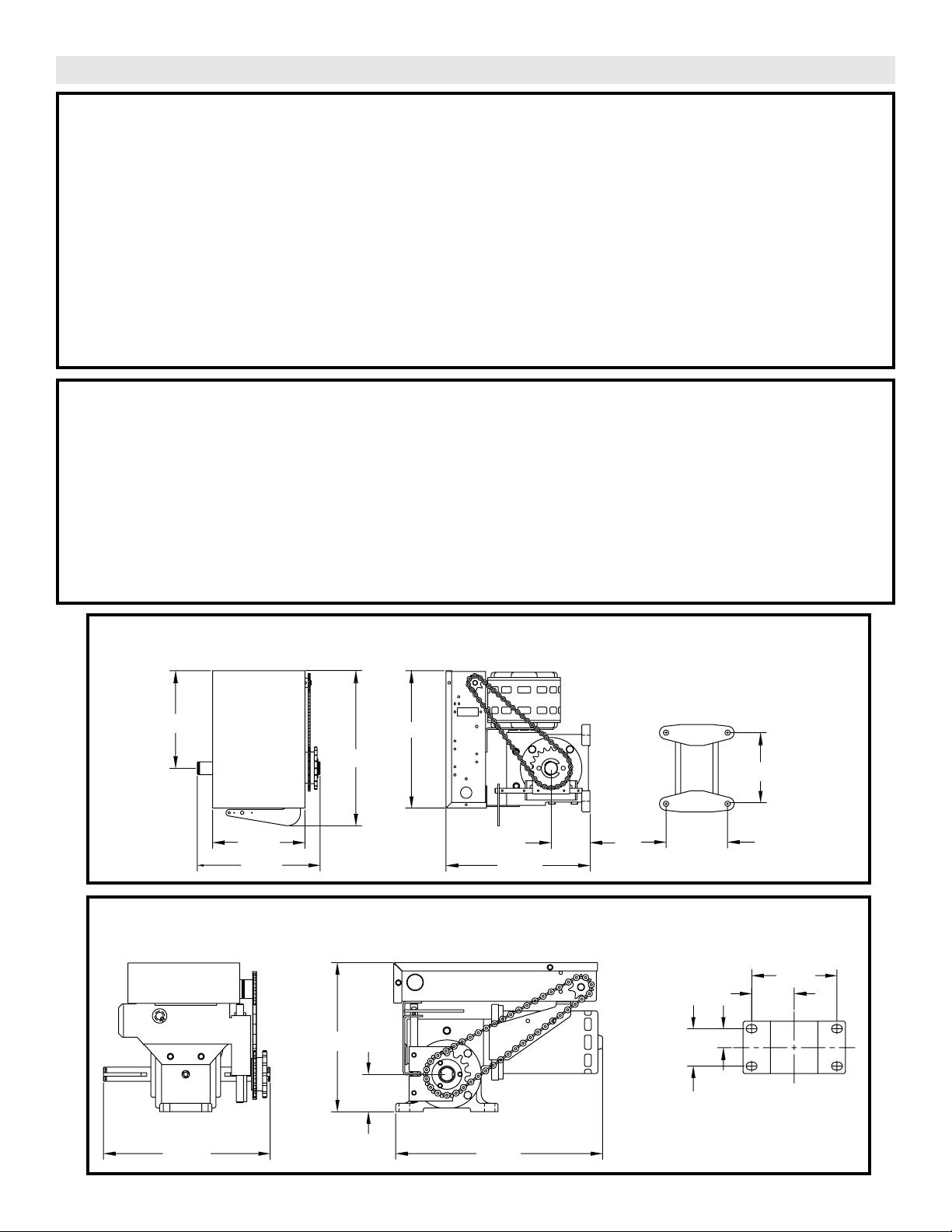
Mounting Dimensions
MOTOR
TYPE: . . . . . . . . . . . . . . . .Intermittent Duty
HORSEPOWER: . . . . . . .MGJ: 1/2 Hp 1 or 3 Phase
LGJ: 1/4 Hp 1 Phase
SPEED: . . . . . . . . . . . . . .MGJ: 1050 RPM
LGJ: 1725 RPM
VOLTAGE: . . . . . . . . . . . .MGJ:115, 60HZ, 1Ph
230V, 50 or 60Hz, 3Ph
230V, 60Hz, 1Ph
380V, 50Hz, 3Ph
460V, 60Hz, 3Ph
LGJ: 115V, 60Hz, 1Ph
CURRENT: See motor nameplate
MECHANICAL
DRIVE REDUCTION: . . . . . . . 40:1 Reduction
(Heavy duty wormgear-in-oil-bath speed reducer)
OUTPUT SPROCKET: . . . . . . Size #41
DOOR SPEED: . . . . . . . . . . . .MGJ: 1Ph, 23RPM
3Ph, 39RPM
. . . . . . . . . . . . . . . . . . . . . . . .LGJ: 1Ph, 43RPM
BEARINGS: . . . . . . . . . . . . . .Heavy duty wormgear-in-
oil-bath speed reducer.
SAFETY
DISCONNECT: . . . . . . . . . . . . . . . .Floor level disconnect
for emergency manual door operation.
REVERSING EDGE (Optional): . . Electric or pneumatic
sensing device attached to the bottom edge of door
A REVERSING EDGE IS STRONGLY RECOMMENDED
FOR ALL COMMERCIAL OPERATOR
INSTALLATIONS. REQUIRED WHEN THE 3 BUTTON
CONTROL STATION IS OUT OF SIGHT OF DOOR OR
ANY OTHER CONTROL (AUTOMATIC OR MANUAL) IS
USED.
SPECIFICATIONS
ELECTRICAL
TRANSFORMER: . . . . . .24VAC
CONTROL STATION: . . .NEMA 1 three button station.
OPEN/CLOSE/STOP
WIRING TYPE: . . . . . . . .MGJ: B2-C2 (Factory Shipped)
LGJ: G2 (Factory Shipped)
See pages 13 and 14 for optional control settings and
operating modes.
LIMIT ADJUST: . . . . . . . .Linear driven, fully adjustable
screw type cams. Adjustable to
24 feet.
LGJ WEIGHTS AND DIMENSIONS
HANGING WEIGHT: 80-110 LBS.
MGJ WEIGHTS AND DIMENSIONS
HANGING WEIGHT: 80-110 LBS.
3
2-1/4"
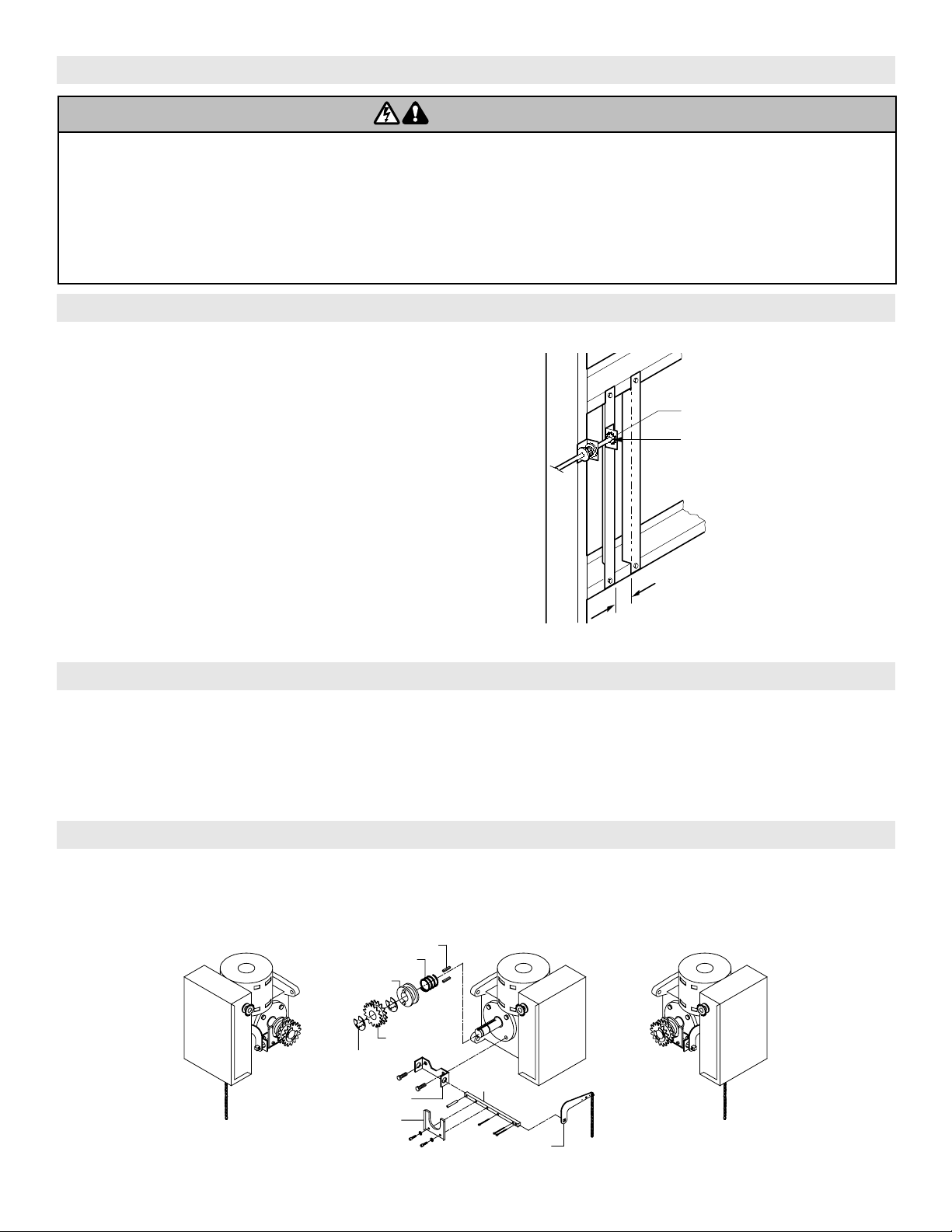
FIGURE 1
Shaft Support Bracket
with Bearing (Not Supplied)
Door Sprocket
2.75 for MGJ, butt together for LGJ
SITE PREPARATIONS
It is imperative that the wall or mounting surface provide
adequate support for the operator.
This surface must:
a) Be rigid to prevent play between operator and door
shaft.
b) Provide a level base.
c) Permit the operator to be fastened securely and with
the drive shaft parallel to the door shaft.
The safety and wear of the operator will be adversely
affected if any of the above requirements are not met.
For metal buildings, fasten 2” x 2” x 3/16” (or larger)
angle iron frames to the building purlins. For proper
spacing, retain .2.75” between for model MGJ, butt
purlins together for model LGJ. See Figure 1.
OPERATOR PREPARATION
IMPORTANT SAFETY NOTES
Model LGJ: Shipped from the factory for right hand mounting, refer to preparation instructions on page 4 for Left hand
mounting.
Model MGJ: Shipped from the factory for either left hand or right hand mounting. Refer to the last digit in the model
number for handing of your unit. If necessary, model MGJ may also be field modified to accommodate
opposite handing. Refer to the conversion instructions below and on page 4.
Disc Lever
Shaft
Bracket
Yok e
Keys
Spring
Disc Hub
Sprocket
E-Ring
MGJ OPPOSITE HANDING PREPARATIONS
1. Remove Disconnect Assembly Components
Remove the master link from the limit chain, remove the
chain and set it aside.
Remove the two E Rings securing the sprocket on the gear
reducer shaft. Remove the screws securing the yoke to the
disconnect shaft, set the yoke aside.
To prevent possible SERIOUS INJURY or DEATH:
• DO NOT connect electric power until instructed to do so.
• If the door lock needs to remain functional, install an interlock
switch.
• ALWAYS call a trained professional door serviceman if door
binds, sticks or is out of balance. An unbalanced door may not
reverse when required.
• NEVER try to loosen, move or adjust doors, door springs,
cables, pulleys, brackets or their hardware, ALL of which are
under EXTREME tension and can cause SERIOUS PERSONAL
INJURY.
• Disable ALL locks and remove ALL ropes connected to door
BEFORE installing and operating door operator to avoid
entanglement.
WARNING
CAUTION
WARNING
WARNING
4
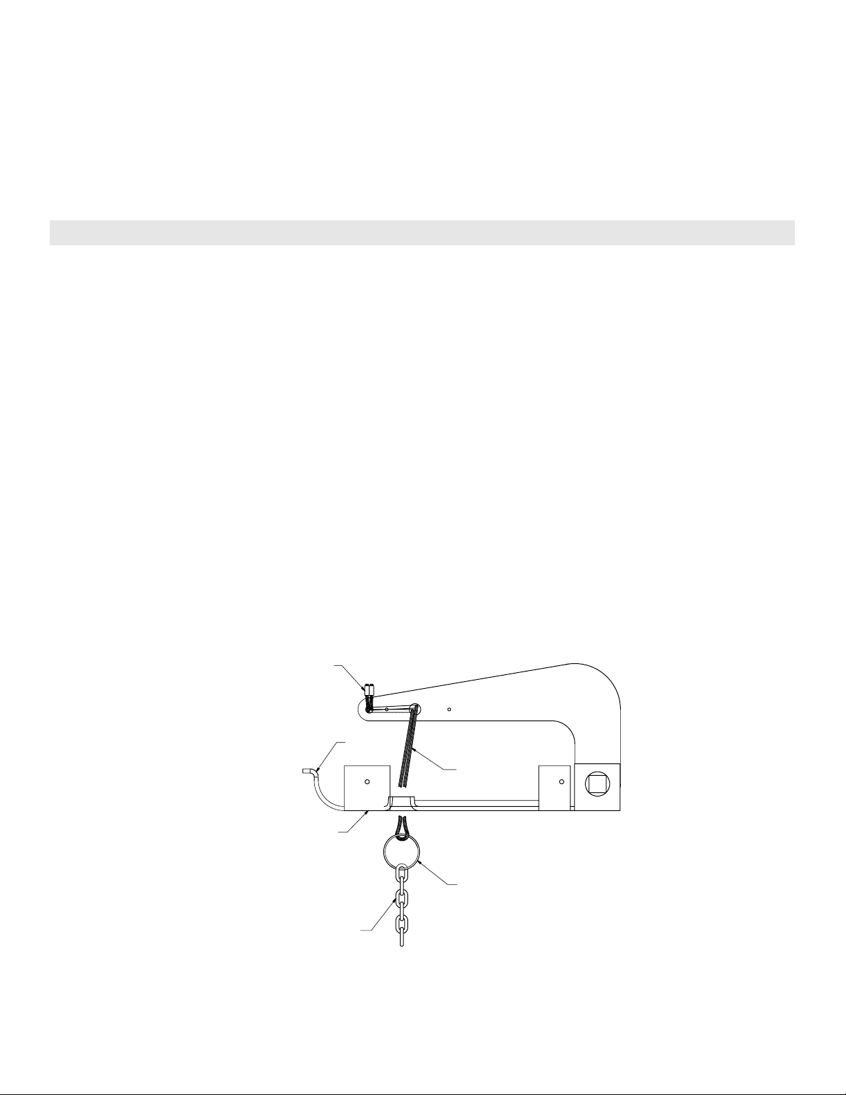
Hour Glass
Cable Sleeve
Release
Cable
slot
Support
Bracket
Key Ring
Sash Chain
LGJ LEFT HAND MOUNTING PREPARATIONS
1. Reconfigure Disconnect Chain Assembly
The default configuration for the disconnect chain
assembly is shown in Figure 1. This configuration allows
the chain to hang freely when the operator is mounted on
right side only. To insure smooth operation of the
disconnect chain assembly when mounted motor side
down, reconfigure as described below and as shown in
figures 2 and 3.
1. Disconnect the key ring from the release cable.
2. Thread the release cable through the slot on the
outermost edge of the support bracket, as shown in
Figure 2.
3. Re-attach the key ring and sash chain to the end of
the loop of release cable.
FIGURE 1
LGJ Operators are assembled at the factory to be installed in a right hand (motor side up) configuration. To install an
LGJ Operator on the left hand side of your door (motor side down), complete the three steps described below.
2. Set Limit Switch Direction
Locate Switch #1 on PCB in the electrical box. Place
pole #2 of Switch #1 in the “OFF” position. With this
setting limit switch labeled “A” is the close switch, limit
switch labeled “B” is the open switch.
IMPORTANT: Refer to page 9 for for complete
instructions on setting of limit switches.
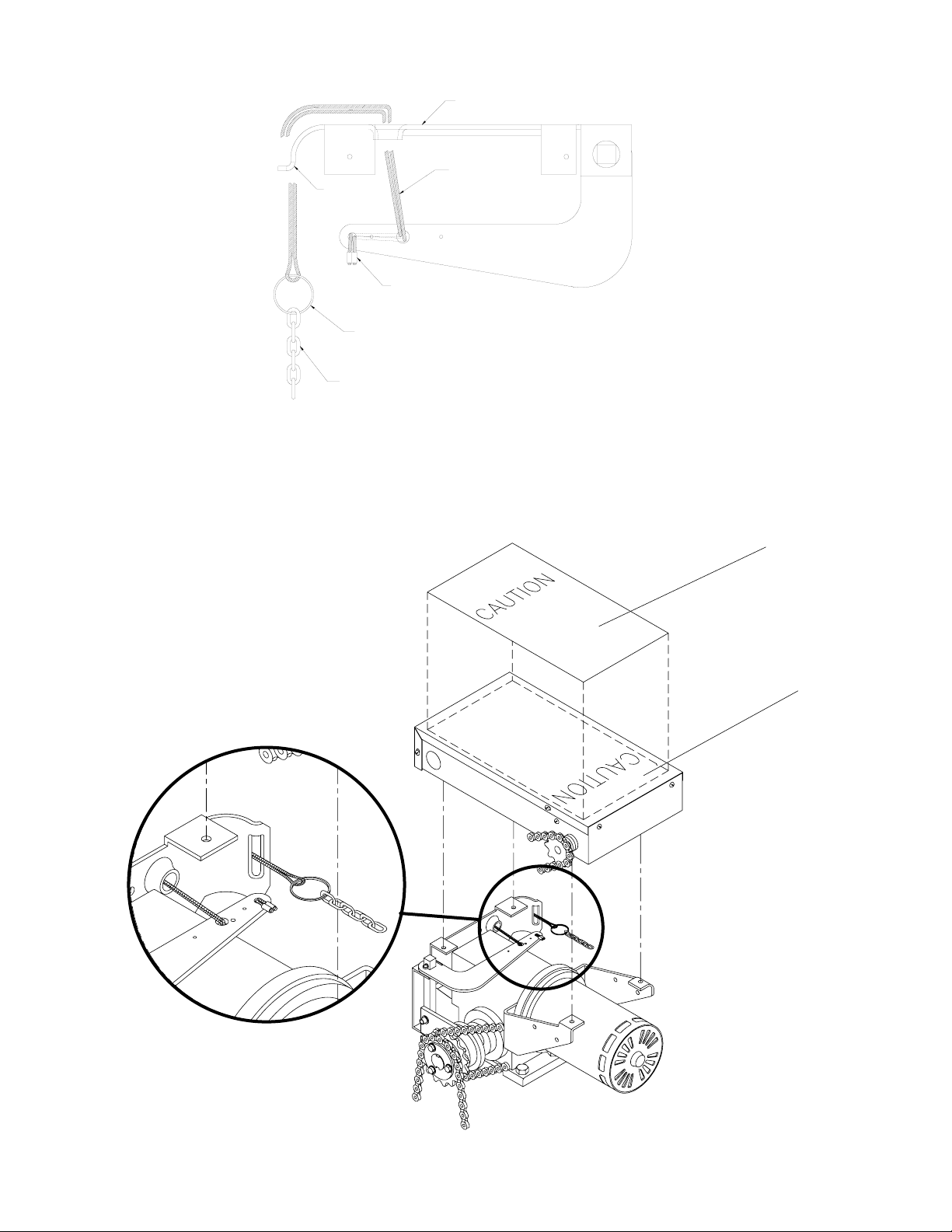
3. Affix Electrical Box Cover Caution Label
Place the caution label on electrical box cover such that
the text is read in the opposite direction of silkscreen.
Disconnect Cable as shipped from the factory
Remove the three cotter pins from the disconnect shaft.
Do not discard the pins. Slide the disconnect shaft out of
the support bracket. The release lever will now be free
inside the motor frame. Remove the release lever and
sash chain from the motor frame. Slide the disconnect
hub, compression spring, and flatwasher from the end of
the gear reducer shaft. Remove the disconnect support
bracket by first removing the the two gear reducer
housing screws. Replace the screws in the gear reducer
and firmly tighten.
2. Re-assemble Disconnect Assembly
Remove the two screws on the opposite side of the gear
reducer and mount the disconnect support bracket with
the notched side facing the motor. For the remainder of
the installation, follow the steps outlined above in reverse
order, referring to the illustration as necessary.
5
Label
Silk
Screen
Hour Glass
Cable Sleeve
Release
Cable
Support
Bracket
Slot
Sash Chain
Key Ring
Disconnect Cable Re-routed for Left Hand Mounting
FIGURE 3
FIGURE 2
6
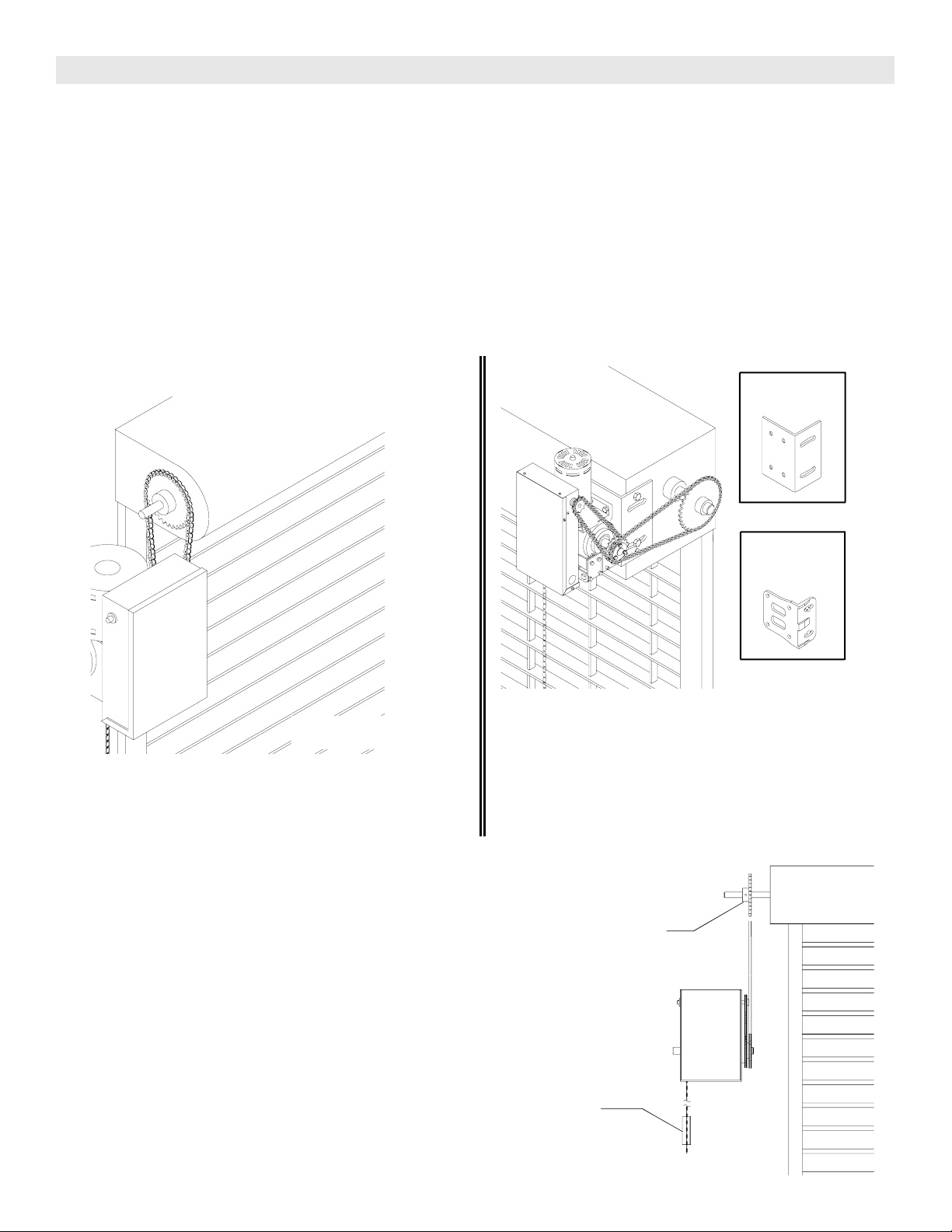
1a. Wall Mounting
The operator should generally be installed below the
door shaft, and as close to the door as possible. The
optimum distance between the door shaft and
operator drive shaft is between 12” - 15”. Refer to
Figure 3.
OPERATOR MOUNTING
IMPORTANT: The shelf or bracket must provide
adequate support, prevent play between operator and
door shaft, and permit operator to be fastened securely
and with the drive shaft parallel to the door shaft.
1b. Bracket or Shelf Mounting
The operator may be mounted either above or below
the door shaft. The optimum distance between the
door shaft and operator drive shaft is between 12” -
15”. Refer to Figure 4.
Typical Right Hand
Wall Mounted Operator
OPTIONAL (LGJ)
Mounting Bracket
P/N 1090951
Be sure door sprocket is
properly aligned with drive
before securing to
the shaft.
Chain Keeper
OPTIONAL (MGJ)
Mounting Bracket
P/N 1A4324
FIGURE 4
FIGURE 3
Before your operator is installed, be sure the door has been properly aligned and is working smoothly. The operator may
be wall mounted or mounted on a bracket or shelf. If necessary, refer to the operator preparations on page 3. Refer to
the illustration and instructions below that suits your application.
FIGURE 5
1c. Place door sprocket on the door shaft. Do not insert
the key at this time.
2. Wrap drive chain around door sprocket and join
roller chain ends together with master link.
3. Raise operator to approximate mounting position and
position chain over operator sprocket.
4. Raise or lower operator until the chain is slightly taut
(not tight). Make sure the operator output shaft is
parallel to door shaft and sprockets are aligned.
When in position, secure the operator to wall or
mounting bracket.
5. Align sprockets and secure, (see Figure 5).
7
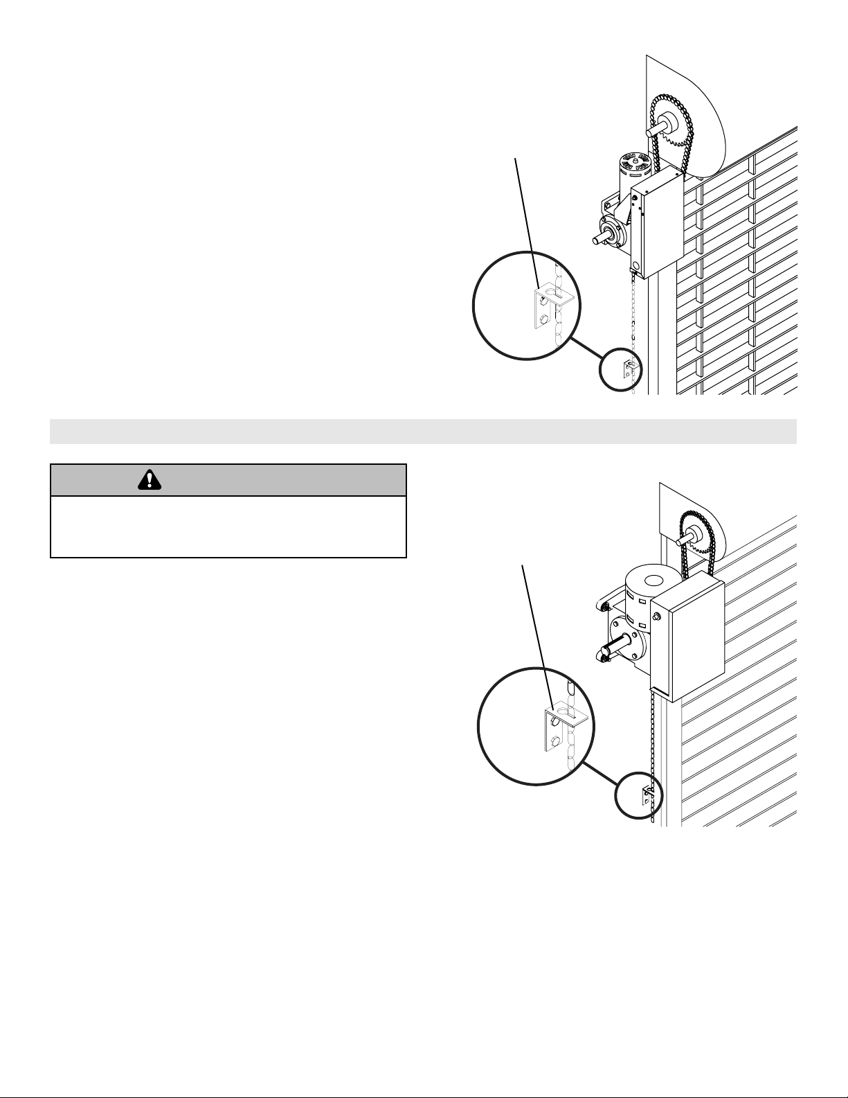
EMERGENCY MANUAL OPERATION
This operator a floor level disconnect chain to disconnect
the door from the door operator allowing for manual
operation of the door in case of emergency or power
failure.
1. To disengage, pull the chain and secure in the
disengaged position by slipping the end through the
keyhole bracket mounted on the wall. Or if emergency
egress device is used, pull handle to disengage
operator from door.
2. The door may now be pushed up or pulled down
manually. Release the disconnect chain to operate the
door again electrically.
6. Mount Chain Keeper / Keyhole Bracket
Using suitable hardware mount the chain keeper
approximately 4 feet above the floor, near the free
hanging chain. Remove disconnect sash chain from
bag and place the end through the keyhole in the the
chain keeper. Remove excess links if necessary.
Keyhole Bracket
Pull sash chain and secure
in bracket for manual
operation of the door.
To prevent possible SERIOUS INJURY from a moving chain,
DISCONNECT electric power to the operator BEFORE
manually operating your door.
WARNING
CAUTION
WARNING
WARNING
8
To avoid SERIOUS PERSONAL INJURY or DEATH from
electrocution, disconnect electric power BEFORE manually
moving limit nuts.
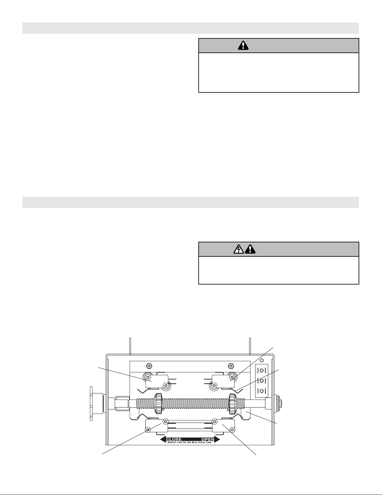
Retaining Plate
CLOSE Limit Switch
SAFETY
(Aux. Close) Limit Switch
OPEN Limit Switch
Actuator
(Aux. Open) Limit Switch
MGJ LIMIT SWITCH ADJUSTMENT
MAKE SURE THE LIMIT NUTS ARE POSITIONED BETWEEN THE LIMIT SWITCH ACTUATORS BEFORE
PROCEEDING WITH ADJUSTMENTS.
SENSING EDGES
All types of sensing edges with an isolated normally
open (N.O.) output are compatible with your operator.
This includes pneumatic and electric edges. If your door
does not have a bottom sensing edge and you wish to
purchase one, contact the supplier of your operator.
If not pre-installed by the door manufacturer, mount the
sensing edge on the door according to the instructions
provided with the edge. The sensing edge may be
electrically connected by either coiled cord or take-up
reel. Refer to the steps below
Important Notes:
a)Proceed with Limit Switch Adjustments before making
any sensing edge wiring connections to operator as
described below.
b)Electrician must hardwire the junction box to the
operator electrical box in accordance with local codes.
ENTRAPMENT PROTECTION ACCESSORIES (OPTIONAL)
TAKE-UP REEL: Take-up reel should be installed 12"
above the top of the door.
COIL CORD: Connect operator end of coil cord to
junction box (not supplied) fastened to the wall
approximately halfway up the door opening.
If other problems persist, call our toll-free number for
assistance - 1-800-528-2806.
1. To adjust limit nuts depress retaining plate to allow
nut to spin freely. After adjustment, release plate and
ensure it seats fully in slots of both nuts.
2. To increase door travel, spin nut away from actuator.
To decrease door travel, spin limit nut toward
actuator.
3. Adjust open limit nut so that door will stop in open
position with the bottom of the door even with top of
door opening.
4. Repeat Steps 1 and 2 for close cycle. Adjust close
limit nut so that actuator is engaged as door fully
seats at the floor.
To reduce the risk of SEVERE INJURY or DEATH, ALWAYS
install reversing sensors when the 3-button control station is
out of sight of door or ANY other control (automatic or
manual) is used. Reversing devices are recommended for ALL
installations.
WARNING
CAUTION
WARNING
WARNING
WARNING
CAUTION
WARNING
WARNING
9
LGJ LIMIT SWITCH ADJUSTMENT
IMPORTANT NOTE: To avoid danger of possible damage to the door and operator, limit switches must be adjusted to
their approximate positions before applying power to the operator.
A. Set Limit Direction Switch
Open the cover on the electrical enclosure and locate dip
switch SW1 on circuit board. The direction of the limit
travel is determined by the switch SW1 - pole #2 setting.
If your operator is mounted Motor Side Up:
Set dip switch SW1 - pole #2 to “ON” position.
If your operator is mounted Motor Side Down:
Set dip switch SW1 - pole #2 to “OFF” position.
NOTE: See Mounting Options on page 5 to verify the
correct mounting application.
As determined by SW1 - pole 2 setting above, locate your
OPEN and CLOSE limit switches. See the figure below
for switch layout.
For Motor Side Up Mounting: Limit switch -A- is the
OPEN limit. Limit switch -B- is the CLOSE limit.
For Motor Side Down Mounting: Limit switch -A- is the
CLOSE limit. Limit switch -B- is the OPEN limit.
Auxiliary limit switches to control other functions are also
present and should not be confused with the -A- and -B-
limit switches. There are two(2) limit nuts on the
threaded shaft that transverse the shaft as the operator
opens and closes the door. When a limit nut nears the
end of the shaft, it activates a switch(es).
B. Manually raise the door to a nearly open position.
(see page 17, Manual Operation)
C. Depress the limit nut retaining bracket away from the
slots in the limit nuts, and manually rotate to the OPEN
limit nut until it depresses the OPEN limit switch lever
(you can hear the switch click when the switch contacts
transfer). Release the retaining bracket and be sure it
engages in the slots of both limit nuts.
D. Manually lower the door to a nearly closed position,
and repeat step C with the CLOSE (right) limit nut.
E. Test Limit Travel
Manually move the door to a half-open position to avoid
damage due to incorrect (dip switch setting) limit travel.
When power is applied, it will cause the door to OPEN
when the limit nuts are traveling in the direction of the
CLOSE limit switch or vice versa. In either instance, the
limit nuts will travel past the limit switch and may cause
damage to both the door and operator. See Step A for
correct setting.
F. After completing the wiring connections on pages 11
thru 13, refer back to step C above for adjustment of limit
switches to their final, exact position.
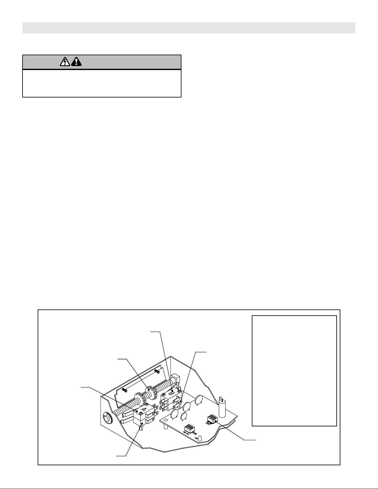
Limit Switch -A-
(Top Switch)
Dip Switch (SW1)
Limit Switch -B-
(Top Switch)
Limit Nut
Limit Switch -A-
(Bottom Switch)
Limit Switch -B-
(Bottom Switch)
If you operator is mounted Motor
Side Up: Set dip switch SW1 - pole
#2 to “ON” position
If your operator is mounted
Motor Side Down: Set dip switch
SW1 - pole #2 to “OFF” position.
When SW1 - pole 2 position is
“ON”: Limit switch -A- is the OPEN
limit. Limit switch -B- is the close
limit.
When SW1 - pole 2 position is
“OFF”: Limit sw itch -A- is the
CLOSE limit. Limit Switch -B- is the
OPEN limit.
Limit Switch Layout
WARNING
CAUTION
WARNING
WARNING
To avoid SERIOUS PERSONAL INJURY or DEATH from
electrocution, disconnect electric power BEFORE manually
moving limit nuts.
10
Use SAE 30 Oil (Never use grease or silicone spray).
Repeat ALL procedures.
Do not lubricate motor. Motor bearings are rated for continuous operation.
Inspect and service whenever a malfunction is observed or suspected.
CAUTION: BEFORE SERVICING, ALWAYS DISCONNECT OPERATOR FROM POWER SUPPLY.
Check at the intervals listed in the following chart.
HOW TO ORDER REPAIR PARTS
OUR LARGE SERVICE ORGANIZATION
SPANS AMERICA
For installation and service information
Call our toll free number - 1-800-528-2806
WHEN ORDERING REPAIR PARTS
PLEASE SUPPLY THE FOLLOWING INFORMATION:
PART NUMBER DESCRIPTION MODEL NUMBER
ADDRESS ORDER TO:
THE CHAMBERLAIN GROUP, INC.
Technical Support Center
6020 S. Country Club
Tucson, AZ 85706
EVERY EVERY EVERY
ITEM PROCEDURE 3 MONTHS 6 MONTHS 12 MONTHS
Drive Chain Check for excessive slack.
Check & adjust as required.
Lubricate.*
Sprockets Check set screw tightness
Fasteners Check & tighten as required
Manual Disconnect Check & Operate
Bearings & Shafts Check for wear & lubricate
MAINTENANCE SCHEDULE
WARNING
CAUTION
WARNING
WARNING
To avoid SERIOUS PERSONAL INJURY or DEATH from
electrocution, disconnect ALL electric power BEFORE
performing ANY maintenance.
11
CONTROL WIRING
Standard C2 or B2 Wiring
Model MGJ operators are shipped from the factory with
jumper set for C2 wiring, which requires constant pressure
on button to close the door. If momentary contact in close
direction is desired (B2 wiring) you must include an
entrapment protection device. See close control jumper
setting below.
Constant pressure on close (C2 wiring)
Red jumper wire was placed on terminal #2 in the
electrical enclosure. The operator will require constant
pressure on close control in order to keep door moving
in the close direction.
Momentary contact on close (B2 wiring)
Move red jumper wire from terminal #2 to terminal #3.
The operator will require only momentary contact to
close the door.
LOCATING THE CONTROL STATION
All operators are supplied with some type of control station. Generally a three button station (OPEN/CLOSE/STOP) is
provided. A two-position key switch or control station (OPEN/CLOSE) may be added or substituted when requested at the
time of order. Mount the control station near the door.
WARNING
W A R N I N G
OPEN
OPEN
CLOSE
CLOSE
STOP
Control Station
WARNING Notice
Push
Buttons
TO PREVENT ENTRAPMENT DO
NOT START DOOR DOWNWARD
UNLESS DOORWAY IS CLEAR
IMPORTANT: Mount WARNING NOTICE beside or
below the push button station.
MOUNT WARNING NOTICE
DETERMINE WIRING TYPE
Refer to the wiring diagram located on the inside cover the electrical box to determine the type of control wiring.
SPECIAL CONTROL WIRING
If your operator was shipped from the factory with non-
standard control wiring or with optional accessories that
require additional instructions, refer to the wiring
diagram(s) indicated in the special control wiring data box.
When a replacement wiring diagram is present, wiring
diagrams in this manual will not apply. Refer only to the
replacement wiring diagram for all connections.
IMPORTANT NOTE: If your wiring diagram is
missing, or you are unsure of the wiring type for
your operator, contact the customer service
department @ 1-800-528-2806.
MODEL MGJ
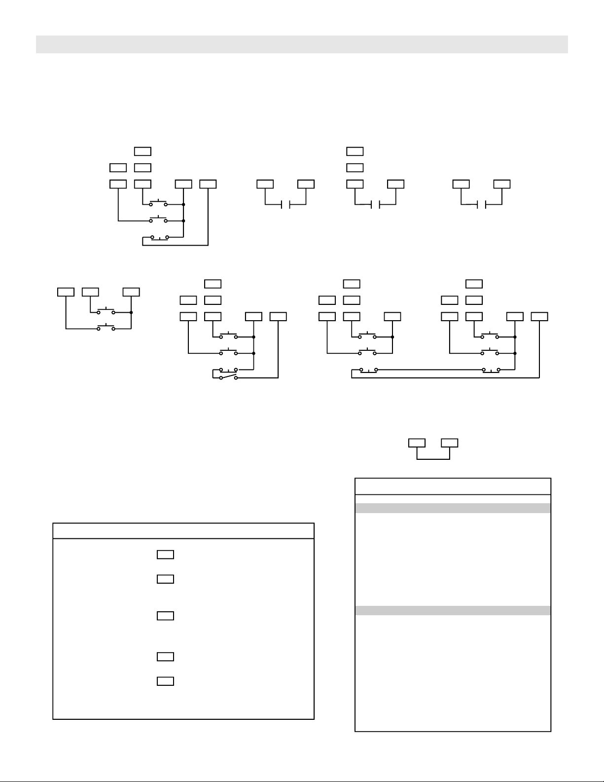
Standard G2 Wiring
Model LGJ operators are supplied with type G2 control
wiring. Study the control features list below to determine
the features and type of control equipment that may be
used with your operator.
Entry Controls:
OPEN control requiring maintained contact.
OPEN control requiring only momentary contact.
CLOSE control requiring maintained contact.
CLOSE control requiring only momentary contact.
OPEN/CLOSE single control requiring momentary contact.
STOP control requiring momentary contact.
Safety Devices:
External Interlock switch to disable all control pneumatic
safety (N.C.) to STOP while closing Safety Device to
REVERSE while closing Door Lock Sensing Circuit.
Operational Features:
REVERSE (if closing) with momentary contact on OPEN.
AUTOMATIC TIMER to CLOSE from any device.
AUTOMATIC TIMER to CLOSE from selected devices.
DELAY REVERSE in either direction for 1 second.
STOP after maximum run time is exceeded.
Note: Refer to LGJ control connection diagrams on
page 15.
MODEL LGJ
To prevent possible SERIOUS INJURY or DEATH, install
reversing sensors when the 3-button control station is out of
sight of the door or ANY other control (automatic or manual)
is used. Reversing devices are recommended for
ALL installations.
WARNING
CAUTION
WARNING
WARNING
12
(OPTIONAL)
BIMETAL
CLOSE-A
* To reverse motor rotation interchange red and yellow motor wires.
Pull switch to
open & close
CLOSE
SAFETY
EDGE
OPEN
BR
2
P
7
Y
10
GY
Y
AUX.
R1
BR
1
OR
GY
OPEN
AUX.
L/S
OPEN-B
BL
OR
12
BL
C
(OPTIONAL)
CLOSE L/S
BK
3
STOP
(HOT) L2
BK
BK
4
R
OPEN-A
W
C
CAPACITOR
Y
N.O.
100W
MAX.
W
LIGHT
RELAY
C
SEC.
OPEN L.S.
CLOSE L/S
P
P
CL
OR
R
N.O.
R
OR
OP
N.C.
C
W
W
W
11
BR
L1 (N)
MOTOR *
R
Y
10VA.
PR1.
24VAC.
Y/BK
W
O/L
BK
A
B
W
WIRE NUT
R3
R2
GY
N.C.
C
Move jumper wire to terminal #2
for momentary contact on close
Y
WIRE NUT
CLOSE-B
RES.
BL
Y
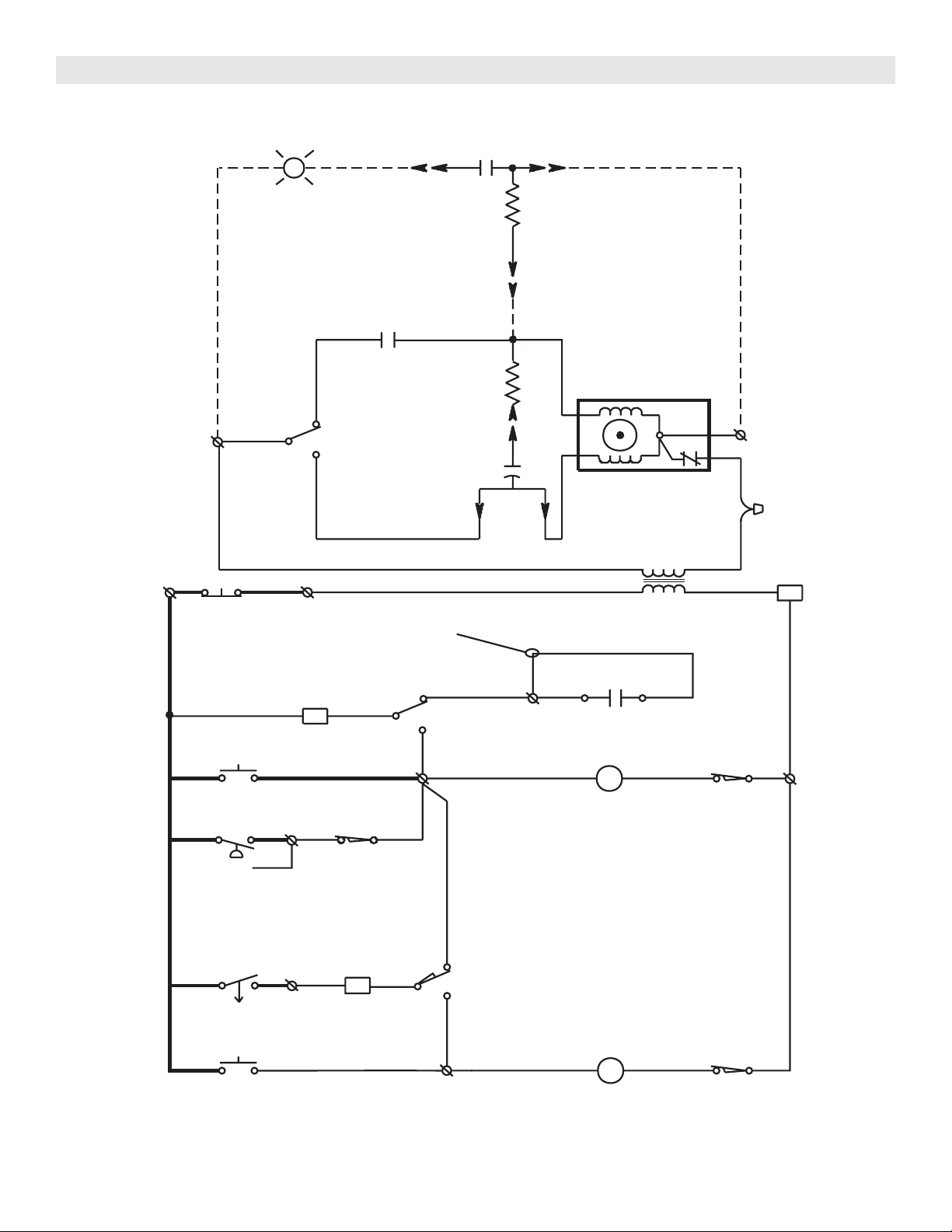
SINGLE PHASE SCHEMATIC DIAGRAM for MGJ
1754
13
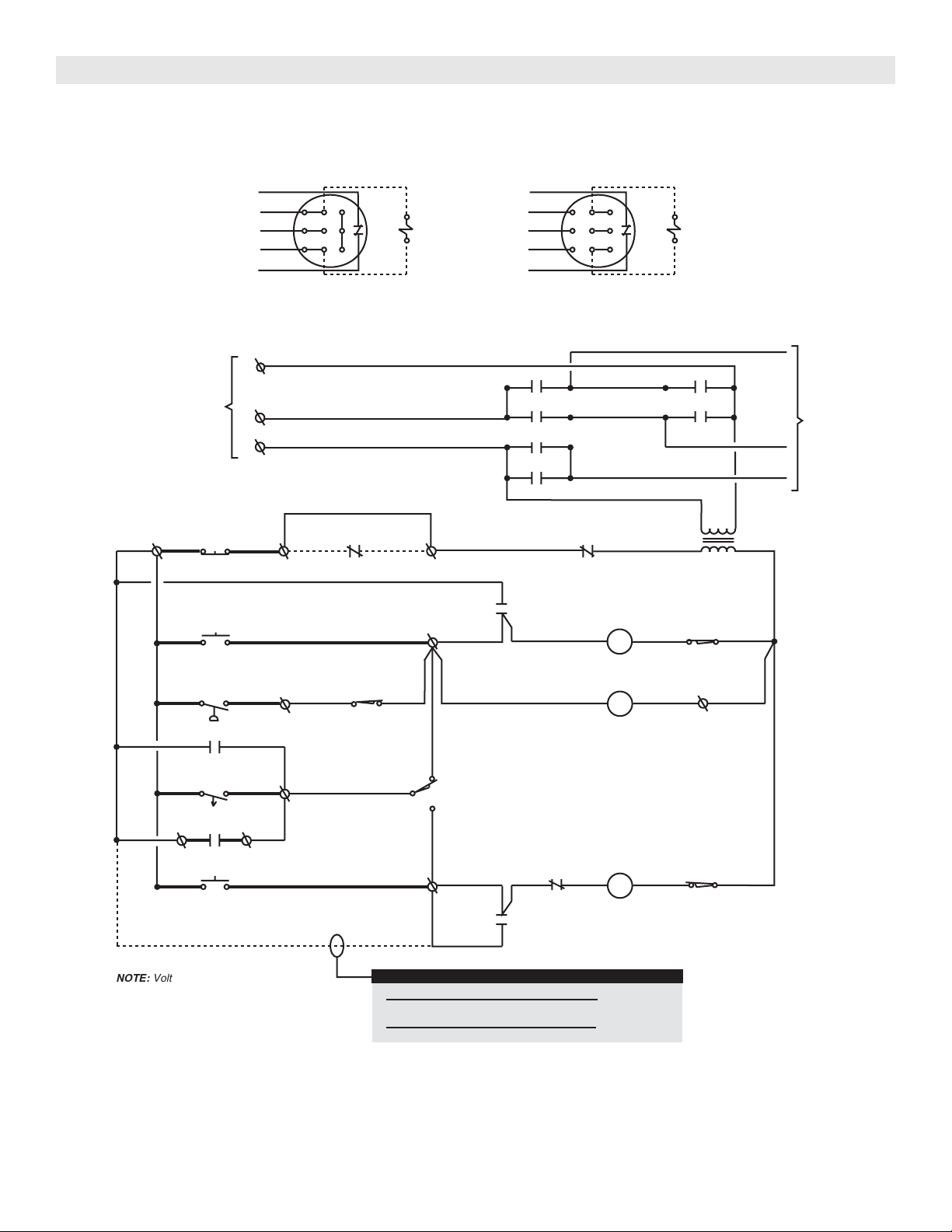
THREE PHASE SCHEMATIC DIAGRAM for MGJ
4
3
5
6
1
2
4
3
2
1
6
5
L3
L2
(GY)
(PUR)
(YEL)
EXTERNAL
STOP
3
54
T1
24VAC
SEC.
PRI.
AUX. CLOSE
LIMIT SWITCH
NC
C
1
7
10
OPEN
SAFETY EDGE
OPEN & CLOSE
LIMIT SWITCH
AUX. OPEN
C
NO
NC
LIMIT SWITCH
NC
C
TO MOTOR
POWER IN
L1
3 PHASE
INTERLOCK
OP
R1
OP
OP
CL
CL
OP
CL
OP
14
13
(IN MOTOR)
R1
OPEN & CLOSE
R2
R1
OPEN
CLOSE
2
14
13
CL
CL
LIMIT SWITCH
NC
CLOSE
C
R1
(BK)
(BK)
(BK)
(BRN)
(BR)
(YEL)
(OR)
(OR)
(OR)
(OR)
(RED)
(RED)
(OR)
(YEL)
(YEL)
(PUR)
(OR)
(PUR)
(PUR) (PUR)
(PUR)
(PUR)
R3
(RED)
(BRN)
(YEL)
(OR)
(OR)
(SEE NOTE #1)
(RED)
(WHEN PRESENT)
230V BRAKE
(GY)
(GY)
RADIO TO
A1
A2
A2 A1
(YEL)
NUT
WIRE
2
3
YEL
BRN
BRN
PUR
GY
1
6
9
BL/BK
BL/BK
O/L
4
7
85
(WHEN PRESENT)
230V BRAKE
2
3
YEL
BRN
BRN
PUR
GY
1
6
9
BL/BK
BL/BK
O/L
4
7
85
230 VOLT - 3 PHASE
MOTOR CONNECTION
460 VOLT - 3 PHASE
MOTOR CONNECTION
*
*
NOTE:
Voltage same as line voltage.
(BK)
(BK)
OVERLOAD
(RED)
C2 WIRING - Constant Presssure to Close
RED WIRE ON TERMINAL #2 (Shipped from Factory)
B2 WIRING - Momentary Contact to Close
MOVE RED WIRE FROM TERMINAL #2 TO TERMINAL #3
*
CLOSE CONTROL WIRING OPTIONS
- Shipped from Factory
*
1819
14
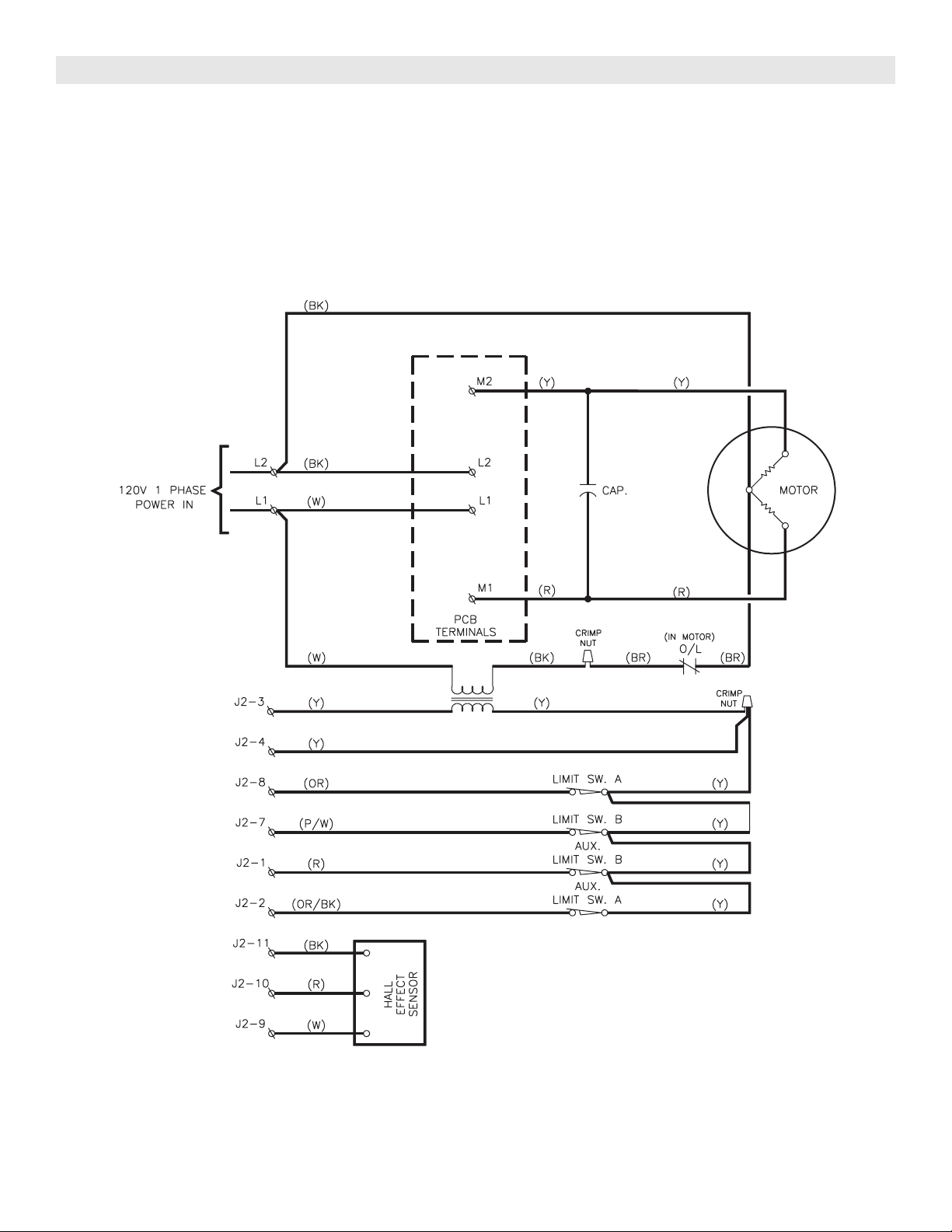
SINGLE PHASE SCHEMATIC DIAGRAM for LGJ
1666
15
LGJ CONTROL CONNECTION DIAGRAM
NUMBERED BOXES CORRESPOND WITH TERMINALS ON J1 CONNECTOR STRIP
If Neccessary, Remove The Connector Block From The Board To Secure Each Wire Connection
Connect field wires to any terminal number shown in the respective column. See control
options below for explanation of how field control will function for each terminal number.
OR
OR
OR
11
97
8435
OPEN
CLOSE
STOP
STANDARD
3 BUTTON CONTROL
10 5
SENSING
EDGE
8 5
9
11
ANY OPEN
CONTROL
(SEE NOTE)
65
ANY
OPEN & CLOSE
CONTROL
(SEE NOTE)
OR
OR
OR
11
97
8435
OPEN
CLOSE
STOP
OR
OR
OR
11
97
845
OPEN
CLOSE
STOP
OR
OR
OR
11
97
8435
OPEN
CLOSE
STOP
OR
OR
1145
OPEN
OFF
ON
CLOSE
2 BUTTON
CONTROL
(SEE NOTE)
3 BUTTON CONTROL
WITH
KEYED LOCK-OUT
3 BUTTON CONTROL
WITH
MULTIPLE CONTROL STATIONS
WHEN CONNECTING AN
OPEN CONTROL TO:
- Open control will require constant
pressure to keep door moving.
- Open control will only require
momentary contact and will set or
reset timer to close.
- Open control will only require
momentary contact and will NOT
set or reset timer to close.
WHEN CONNECTING AN
CLOSE CONTROL TO:
- Close control will require constant
pressure to keep door moving.
- Close control will only require
momentary contact.
DO NOT add unless using an
entrapment Protection device.
11
9
8
4
7
OPEN AND CLOSE CONTROL OPTIONS
IMPORTANT NOTE:
WHEN STOP BUTTON IS NOT USED, ADD A JUMPER FROM
TERMINAL 3 TO TERMINAL 5.
35
MAXIMUM RUN TIME: 1 - ON: Maximum run time is 90 seconds.
OFF: Maximum run time is 45 seconds.
MAXIMUM RUN TIME: 2 - ON: CLOSE limit switch B
OFF: CLOSE limit switch A
3 - OFF: (DO NOT ADJUST)
4 - OFF: (DO NOT ADJUST)
CONSULT FACTORY FOR ADJUSTEMENT
SWITCH #1 SETTINGS
SWITCH #2 SETTINGS
TIMER TO CLOSE SWITCH SETTING:
O = ON F = OFF
1 2 3 4
O O O O
F O O O
O F O O
F F O O
O O F O
F O F O
O F F O
F F F O
1 2 3 4
O O O F
F O O F
O F O F
F F O F
O O F F
F O F F
O F F F
F F F F
= Disabled
= 2 sec
= 3 sec
= 13 sec
= 15 sec
= 23 sec
= 32.5 sec
= 43.6 sec
= 72 sec
= 88 sec
= 107 sec
= 126sec
= 148 sec
= 172 sec
= 198 sec
= 224 sec
SETTING SETTINGTIME TIME
SWITCH ADJUSTMENTS
OR
OR

16
REPLACEMENT PART KITS LGJ
SOLID STATE
Item P/N Description Qty
Below are replacement kits available for your operator. Optional modifications and/or accessories included with your
operator may add or remove certain components from these lists. Please consult a parts and service representative
regarding availability of individual components of kits specified below. Refer to page 10 for all repair part ordering
information.
K72-12581 LIMIT SHAFT ASSEMBLY KIT
Item
L1
L2
L3
L4
L5
L6
L7
L8
L9
L10
Description
Limit Shaft
3/8” Bearing, Plastic Flange
Limit Nut
Sprocket, 48B07
Rotor for RSL Assembly
Washer, Shim
Washer, Shim
Washer, Shim
Roll Pin, 1/8” Dia. x 3/4” Long
E Ring, 3/8”
Qty
1
2
2
1
1
1
1
1
1
3
K75-12582 LIMIT SWITCH ASSEMBLY KIT
Complete Electrical Box Replacement Kit
K-LGJ2511 Model LGJ2511
Electrical Box Sub-Assembly Kits
K72-12581 LGJ Limit Shaft Assembly
K75-12582 LGJ Limit Switch Assembly
K79-11384 LGJ PC Board Assembly
P/N
11-11425
12-10458
13-10024
15-48B07AXX
81-11443
80-10053
80-10025
80-10026
86-RP04-012
87-E-038
Item
S1
S2
S3
S4
S5
S6
S7
S8
Description
Depress Plate
Spring, Depress Plate
Limit Switch
Limit Switch
Standoff, #4-40 Threaded x .19 Long
Screw, #4-40 x 1” Pan Head Ph
Screw, #6-32 x 1” Pan Head Ph
Locknut #6-32
Qty
1
2
2
2
4
4
2
2
P/N
10-11391
18-10036
23-10041
23-11442
80-11445
82-PX04-16
82-PX06-16
84-LH-06
10-11390M1
10-11392M1
21-13395
29-7642
42-9306
42-13378
75-11395
79-11378
80-10027
11-11425
12-10458
13-10024
15-48B07AXX
81-11443
85-FW-38
86-RP04-012
87-E-038
10-11391
18-10036
23-10041
23-11442
80-11446
82-PX04-16
82-PX06-16
84-LH-06
1
2
3
4
5
6
7
8
9
L1
L2
L3
L4
L5
L6
L7
L8
S1
S2
S3
S4
S5
S6
S7
S8
1
1
1
1
1
1
1
1
4
1
2
2
1
1
4
1
1
1
2
2
2
4
4
2
2
Electrical Box Cover
Electrical Box
Transformer, LGJ 115V-24VAC
Capacitor 220V 42MFD
Terminal Block 6 Pole
J2 Terminal Block, 16 Pole (1-16)
Hall Effect Assembly
PCB Board Assembly
PCB Board Standoff
Limit Shaft
3/8” Bearing, Plastic Flange
Limit Nut
Sprocket, 48B07
Rotor for RSL Assembly
Flat Washer, 3/8”
Roll Pin, 1/8” Dia. x 3/4” Long
E Ring, 3/8”
Depress Plate
Spring, Depress Plate
Limit Switch
Limit Switch
Standoff, #4-40 Threaded x .19 Long
Screw, #4-40 x 1” Pan Head Ph
Screw, #6-32 x 1” Pan Head Ph
Locknut #6-32
COMPLETE ELECTRICAL BOX KITS
Disconnect Assembly Kit
K75-12583 Model LGJ2511
17
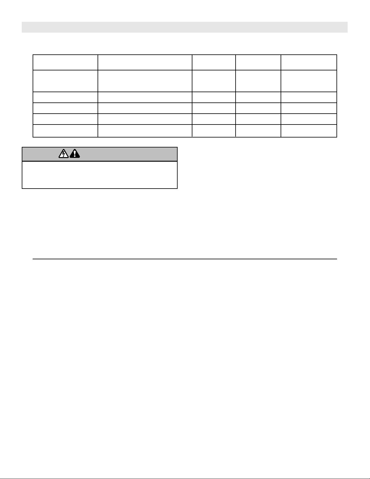
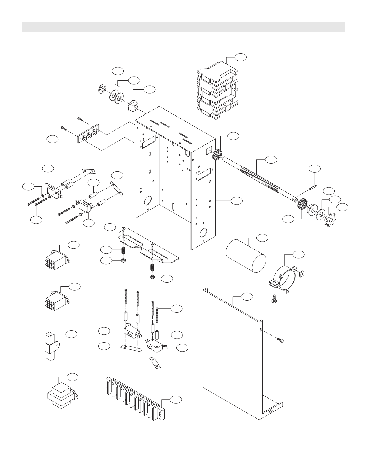
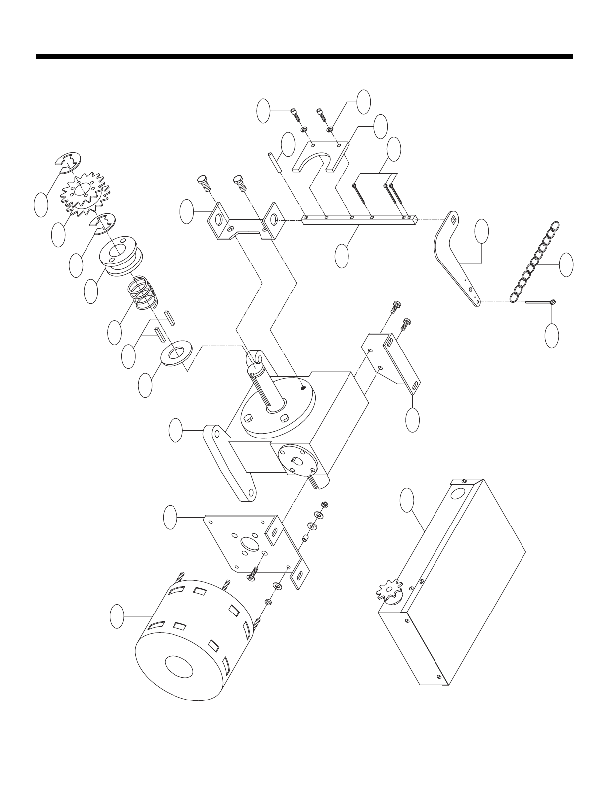
LGJ ELECTRICAL BOX - ILLUSTRATED PARTS
1
L3
L1
L5
L9
L3
7
L10
L7
L2
4
3
S2
S8
S3
S5
S4
S6
S1
2
5
9
8
S7
L2
L6
L4
6
L10
L10
L8

18
REPLACEMENT PART LISTS – MODEL LGJ
Refer to the parts lists below for replacement kits available for your operator. If optional modifications and/or accessories
are included with your operator, certain components may be added or removed from these lists. Individual components
of each kit may not be available. Please consult a parts and service representative regarding availability of individual
components. Refer to page 10 for all repair part ordering information.
K75-12583 DISCONNECT ASSEMBLY KIT
ITEM PART # DESCRIPTION QTY
D1
D2
D3
D4
D5
D6
D7
D8
D9
D10
D11
D12
D13
Bevel Gear Yoke
Disconnect
Release Lever
Retaining Plate
Disconnect Shaft
Sprocket, 48B14/41B14
Compression Spring
Key, 1/4 x 1-1/2” Long
Screw, #10-32 x 1/2” Hex
Flatwasher, 3/4”
Cotter Pin 1/8” x 1-3/4” Long
Roll Pin, 1/8” Dia. x 1” Long
E Ring 3/4”
1
1
1
1
1
1
1
1
5
1
1
1
1
10-11023
10-11393
10-11394
10-11399
11-11424
15-11379
18-11427
80-207-19
82-HX10-08T
85-FW-75
86-CP04-112
86-RP04-100
87-E-075
INDIVIDUAL PARTS
ITEM PART # DESCRIPTION QTY
1
2
3
4
5
6
7
Support Bracket
Mounting Bracket (LH)
Mounting Bracket (RH)
Gear Reducer, 40:1
Electrical Box
Motor Kit
Nut
1
1
1
1
1
1
4
10-11397
10-11389-1
10-11398-2
32-11435
See Page 16
K20-1025C1
84-FN-10
19
LGJ ILLUSTRATED PARTS
D3
5
2
1
D5
D11
D12
D1
4
6
D10
D7
D2
D9
3
D8
D6
D13
D4
D9

20
Below are replacement kits available for your operator. For replacement of electrical box, motor or brake components be
sure to match model number of your unit to kit number below to ensure proper voltage requirements. Optional
modifications and/or accessories included with your operator may add or remove certain components from these lists.
Please consult a parts and service representative regarding availability of individual components of kits specified below.
Refer to page 10 for all repair part ordering information.
REPLACEMENT PART KITS MGJ
NOTES:
1) Reversing Contactor (03-11112), Used only on three
phase operators. Single phase operators use relays.
2) Capacitor (29-10338), Capacitor Clamp (10-11421)
and Resistor (29-2) used only on single phase
operators.
Complete Electrical Box Replacement Kits
K-MGJ5011L Model MGJ5011L
K-MGJ5023L Model MGJ5023L
K-MGJ5025L Model MGJ5025L
K-MGJ5038L Model MGJ5038L
K-MGJ5043L Model MGJ5043L
K-MGJ5011R Model MGJ5011R
K-MGJ5023R Model MGJ5023R
K-MGJ5025R Model MGJ5025R
K-MGJ5038R Model MGJ5038R
K-MGJ5043R Model MGJ5043R
Electrical Box Sub-Assemblies
K72-12565 MGJ Limit Shaft Assembly
K75-12566 MGJ Limit Switch Assembly
COMPLETE ELECTRICAL BOX KITS
P/N
03-11112
10-11403
10-11420
10-11421
(See Var. Comp.)
24-24-1
29-10338
29-2
42-10040
42-110
11-11373
12-10458
13-10024
15-48B07AXX
80-10026
85-FW-38
86-RP04-012
87-E-038
10-11419
18-10036
23-10041
31-13062
82-PX06-16
82-PX06-19
84-DT-06
84-LH-06
Item
1
2
3
4
5
6
7
8
9
10
L1
L2
L3
L4
L5
L6
L7
L8
S1
S2
S3
S4
S5
S6
S7
S8
Qty
1
1
1
1
1
2
1
1
1
1
1
2
2
1
1
2
1
1
1
2
4
8
2
8
4
2
Description
Reversing Contactor (See Notes)
Electrical Box Cover
Electrical Box
Capacitor Clamp (See Notes)
Transformer
24V DPDT Relay
Capacitor, 7MFD (See Notes)
Resistor, 20 Ohm
Terminal Block Assy, 3 Lug
10 Position Terminal Block
MGJ Limit Shaft
3/8” Bearing, Plastic Flange
Limit Nut
Sprocket, 48B07
Washer, Shim 3/8” I.D. x .01
Flatwasher, 3/8”
Roll Pin, 1/8” Dia. x 3/4” Long
E Ring, 3/8”
Depress Plate
Spring, Depress Plate
SPDT Limit Switch
Spacer, .115” ID x 5/8” Long
Screw, #6-32 x 1” Pan HD PH
Screw, #6-32 x 1-3/8” Pan HD PH
Nut, #6-32 Double Tinnerman
Locknut #6-32
K72-12565 LIMIT SHAFT ASSEMBLY KIT
Item
L1
L2
L3
L4
L5
L6
L7
L8
Description
MGJ Limit Shaft
3/8” Bearing, Plastic Flange
Limit Nut
Sprocket, 48B07
Washer, Shim 3/8” I.D. x .01
Flatwasher, 3/8”
Roll Pin, 1/8” Dia. x 3/4” Long
E Ring, 3/8”
Qty
1
2
2
1
1
2
1
1
K75-12566 LIMIT SWITCH ASSEMBLY KIT
P/N
11-11373
12-10458
13-10024
15-48B07AXX
80-10026
85-FW-38
86-RP04-012
87-E-038
Item
S1
S2
S3
S4
S5
S6
S7
S8
Description
Depress Plate
Spring, Depress Plate
SPDT Limit Switch
Spacer, .115” ID x 5/8” Long
Screw, #6-32 x 1” Pan HD PH
Screw, #4-40 x 1-1/2” Pan HD PH
Nut, #6-32 Double Tinnerman
Locknut #6-32
Qty
1
2
4
8
2
8
4
2
P/N
10-11419
18-10036
23-10041
31-13062
82-PX06-16
82-PX04-20
84-DT-06
84-LH-06
VARIABLE COMPONENT KITS
P/N
21-5115
21-5230
21-5460
Description
Transformer, 115V
Transformer, 230V
Transformer, 460V
MGJ5011
MGJ5023
MGJ5043
MGJ5025
MGJ5038
Item
5
Motor Kits
K20-1050C1M Model MGJ5011
K20-3050C4M Models MGJ5023,MGJ5038,MGJ5043
K20-5150C6M Model MGJ5025
Disconnect Assembly Kit
K75-12567 Model MGJ Operators
21
L8
L6
L2
1
L3
L1
L7
L2
4
7
3
9
S3
S9
S7
S4
S6
S3
S5
6
6
8
5
S2
S8
S1
2
S3
S7
S6
S4
S3
10
L3
L4
L5
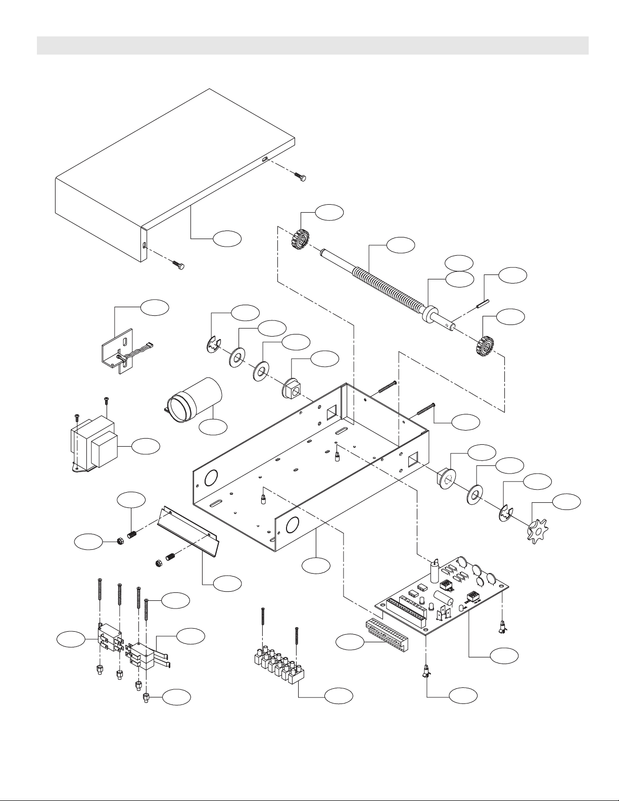
MGJ ELECTRICAL BOX - ILLUSTRATED PARTS

22
REPLACEMENT PART LISTS – MODEL MGJ
Refer to the parts lists below for replacement kits available for your operator. If optional modifications and/or
accessories are included with your operator, certain components may be added or removed from these lists. Individual
components of each kit may not be available. Please consult a parts and service representative regarding availability of
individual components. Refer to page 10 for all repair part ordering information.
K75-12567 DISCONNECT ASSEMBLY KIT
ITEM PART # DESCRIPTION QTY
D1
D2
D3
D4
D5
D6
D7
D8
D9
D10
D11
D12
D13
D14
D15
Disconnect Hub
Bevel Gear Yoke
Disconnect Support Bracket
Release Lever
Disconnect Shaft MGJ
Sprocket, 41B19 x 1.25 Bore
Compression Spring
12ft. Of Sash Chain
Disconnect Key 1/4 x 1/4 x 7/8
Washer, 1” I.D. x 1/16” Thick
Screw, #10-32 Hex Head Socket
#10 Lock Washer ZP
Cotter Pin, 1/8” x 1-3/4” Long
Roll Pin, 1/8” Dia. x 1” Long
E Ring, 1” Plated
1
1
1
1
1
1
1
1
2
1
2
2
4
1
2
07-11418
10-11023
10-11358
10-11394
11-11361
15-11377
18-10467
19-8A-12
80-11416
80-206-11
82-SH10-12
85-LS-10
86-CP04-112
86-RP04-100
87-E-100
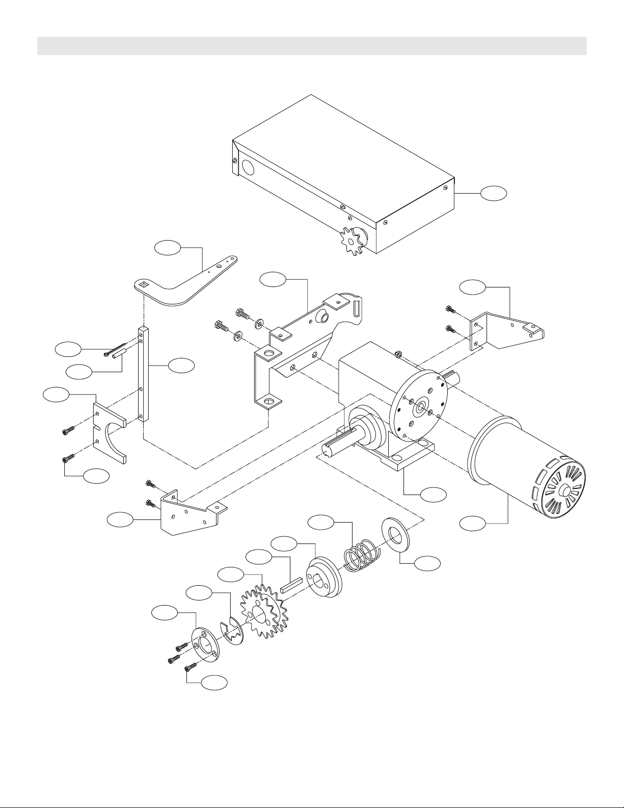
INDIVIDUAL PARTS
ITEM PART # DESCRIPTION QTY
1
2
3
4
5
Brake Mounting Plate
Front Bracket
Gear Reducer, 45:1
Electrical Box
Motor
1
1
1
1
1
10-11357
10-11359
32-11414
See Page 20
See Page 20
23
8D
31D
4
5
1
3
01D
9D
7D
1D
51D
6D
51D
3D
4D
5D
31D
2D
21D
41D
11D
2
ILLUSTRATED PARTS – MODEL MGJ
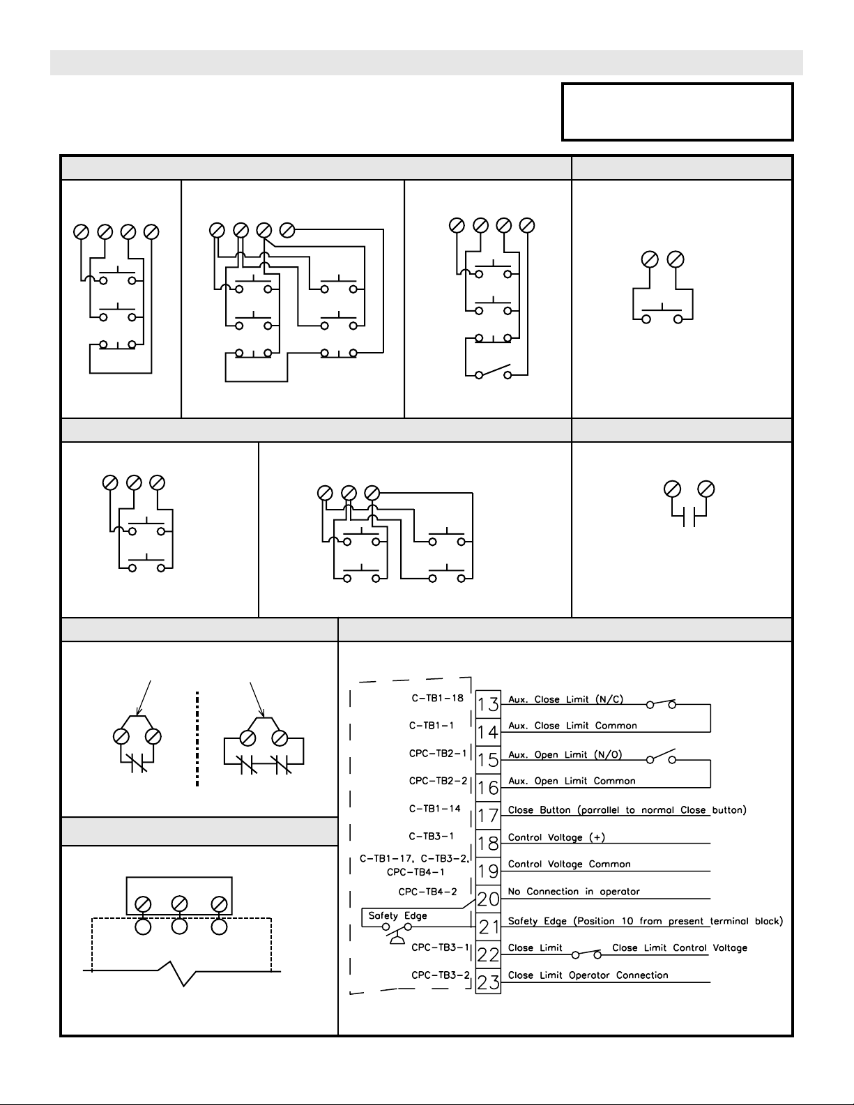
MGJ CONTROL CONNECTION DIAGRAM
©
2006, The Chamberlain Group, Inc.
01-11452J
All Rights Reserved
3 BUTTON STATION or 3 POSITION KEYSWITCH w/ SPRING RETURN TO CENTER AND STOP BUTTON
2 OR MORE
KEY LOCKOUT
R1
R2
R3
1234
Stop
Close
Open
Stop
Close
Open
1234
Stop
Close
Open
2 BUTTON STATION or 3 POSITION KEYSWITCH w/ SPRING RETURN TO CENTER
STANDARD
124
Close
Open
ALL CONTROL
WIRING TYPES
2 OR MORE
124
Close
Open
Close
Open
OPEN / CLOSE
3
7
RADIO CONTROL
1 BUTTON STATION or ANY AUXILIARY DEVICE
RESIDENTIAL RADIO CONTROLS
SENSING DEVICE TO REVERSE OR STOP
EXTERNAL INTERLOCK (THREE PHASE ONLY)
20
21
4
5
4
5
Remove Jumper
When Interlock is Used
ONE
2 OR MORE
STANDARD
1234
Stop
Close
Open
IMPORTANT NOTES:
1) The 3-Button Control Station provided must be connected for operation.
2) If a STOP button is not used, a jumper must be placed between terminals 3 and 4.
3) Auxiliary control equipment may be any normally open two wire device such as
pull switch, single button, loop detector, card key or such device.
Keyswitch
Sensing Device
ALL CONTROL WIRING TYPES
B2 or T1
WIRING TYPES ONLY
EXTERNAL
TERMINAL BLOCK
ALL CONTROL WIRING TYPES
ALL CONTROL WIRING TYPES
ALL CONTROL WIRING TYPES
ALL CONTROL WIRING TYPES
ATTENTION ELECTRICIAN:
USE 16 GAUGE OR HEAVIER WIRE
FOR ALL CONTROL CIRCUIT WIRING.
SEE NOTE #2
SEE NOTE #2
SEE NOTES
#2 AND #3
INTERCONNECTIONS SS90 FIRE DOOR CONTROLLER
ALL CONTROL WIRING TYPES
SS90 FIRE CONTROL
TERMINAL BLOCK
MGJ "SS90"
TERMINAL BLOCK
NOTE: There are two boards in an SS90-CPC unit; the "C" and the "CPC". Therefore, connections are listed by
Board - Terminal Block - Position. (Example CPC-TB3-2 designates a connection to the "CPC" board,
terminal block 3, position 2)
(Refer to page 15 for model LGJ control connections)