Loading ...
Loading ...
Loading ...
3.
OUTDOOR
UNIT
INSTALLATION
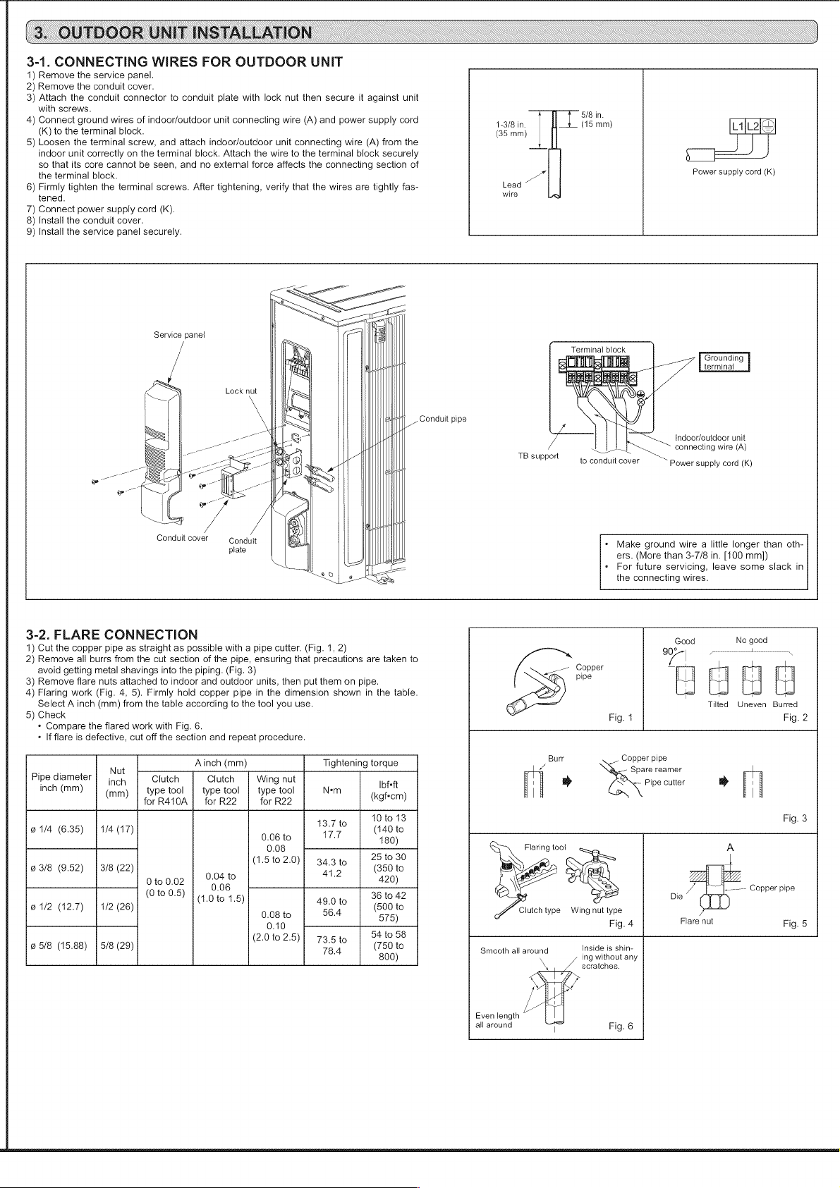
3-1.
CONNECTING
WIRES
FOR
OUTDOOR
UNIT
1)
Remove
the
service
panel.
2)
Remove
the
conduit
cover.
3)
Attach
the
conduit
connector
to
conduit
plate
with
lock
nut
then
secure
it
against
unit
with
screws.
5/8
i
4)
Connect
ground
wires
of
indoor/outdoor
unit
connecting
wire
(A)
and
power
supply
cord
4-3/8
in
|
(15
mm)
(K)
to
the
terminal
block.
(35
mm)
5)
Loosen
the
terminal
screw,
and
attach
indoor/outdoor
unit
connecting
wire
(A)
from
the
indoor
unit
correctly
on
the
terminal
block.
Attach
the
wire
to
the
terminal
block
securely
so
that
its
core
cannot
be
seen,
and
no
external
force
affects
the
connecting
section
of
the
terminal
block.
a
Power
supply
cord
(K)
6)
Firmly
tighten
the
terminal
screws.
After
tightening,
verify
that
the
wires
are
tightly
fas-
Lead
tened.
wire
7)
Connect
power
supply
cord
(kK).
8)
Install
the
conduit
cover.
9)
Install
the
service
panel
securely.
ee
ee
Se
il
Service
panel
|
a
Terminal
block
a
="
=
FOUNCING
iL
iS
terminal
Lock
nut
Conduit
pipe
Indoor/outdoor
unit
Jot
connecting
wire
(A)
7B
support
to
conduit
cover
Power
supply
cord
(K)
Conduit
cover
Conduit
plate
«
Make
ground
wire
a
little
longer
than
oth-
ers.
(More
than
3-7/8
in.
[100
mm])
For
future
servicing,
leave
some
slack
in
the
connecting
wires.
3-2.
FLARE
CONNECTION
ood
No
good
1)
Cut
the
copper
pipe
as
straight
as
possible
with
a
pipe
cutter.
(Fig.
1,
2)
90°
pov
Lenn
~
2)
Remove
all
burrs
from
the
cut
section
of
the
pipe,
ensuring
that
precautions
are
taken
to
/
|
avoid
getting
metal
shavings
into
the
piping.
(Fig.
3)
a
Copper
~
3)
Remove
flare
nuts
attached
to
indoor
and
outdoor
units,
then
put
them
on
pipe.
pip
4)
Flaring
work
(Fig.
4, 5).
Firmly
hold
copper
pipe
in
the
dimension
shown
in
the
table.
i i i
Select
A
inch
(mm)
from
the
table
according
to
the
tool
you
use.
Tilted
Uneven
Burred
5)
Check
Fig.
4
Fig.
2
«
Compare
the
flared
work
with
Fig.
6.
g 9
«
If
flare
is
defective,
cut
off
the
section
and
repeat
procedure.
° A .
Burr
Copper
pipe
Nut
Ainch
(mm)
Tightening
torque
Z
Spare
reamer
Pipe
diameter
|
joy
Clutch
Clutch
|
Wing
nut
Ibfeft
;
>
EO
Pipe
cutter
»
;
inch
(mm)
type
tool
|
type
tool
|
type
tool
Nem
(mm)
(kgf*cm)
| |
for
R410A
|
for
R22
for
R22
10
to
13
Fig.
3
@1/4
(6.35)
|
1/4
(17)
13.7
to
(140
to
0.06
to
17.7
180)
fee
25
to
30
;
1.5
to
2.0
o
23/8
(9.52)
|
3/8
(22)
(
}}
343t0
|
“356
to
0.04
to
41.2
420
0
to
0.02
)
;
0.06
.—--—
Copper
pipe
(0
to
0.5)
(1.0
to
1.5)
49.0
to
36
to
42
Die
@
1/2
(12.7)
1/2
(26)
0.08
to
56.4
O75).
-
Clutch
type
Wing
nut
type
0.10
Fig.
4
Flare
nut
Fig.
5
(2.010
2.5)
73.5to
|
54
'058
@
5/8
(15.88)
|
5/8
(29)
78.4
S00)”
Smooth
all
around
ing
without
any
scratches.
Even
length
all
around
Fig.
6
Loading ...
Loading ...