Loading ...
Loading ...
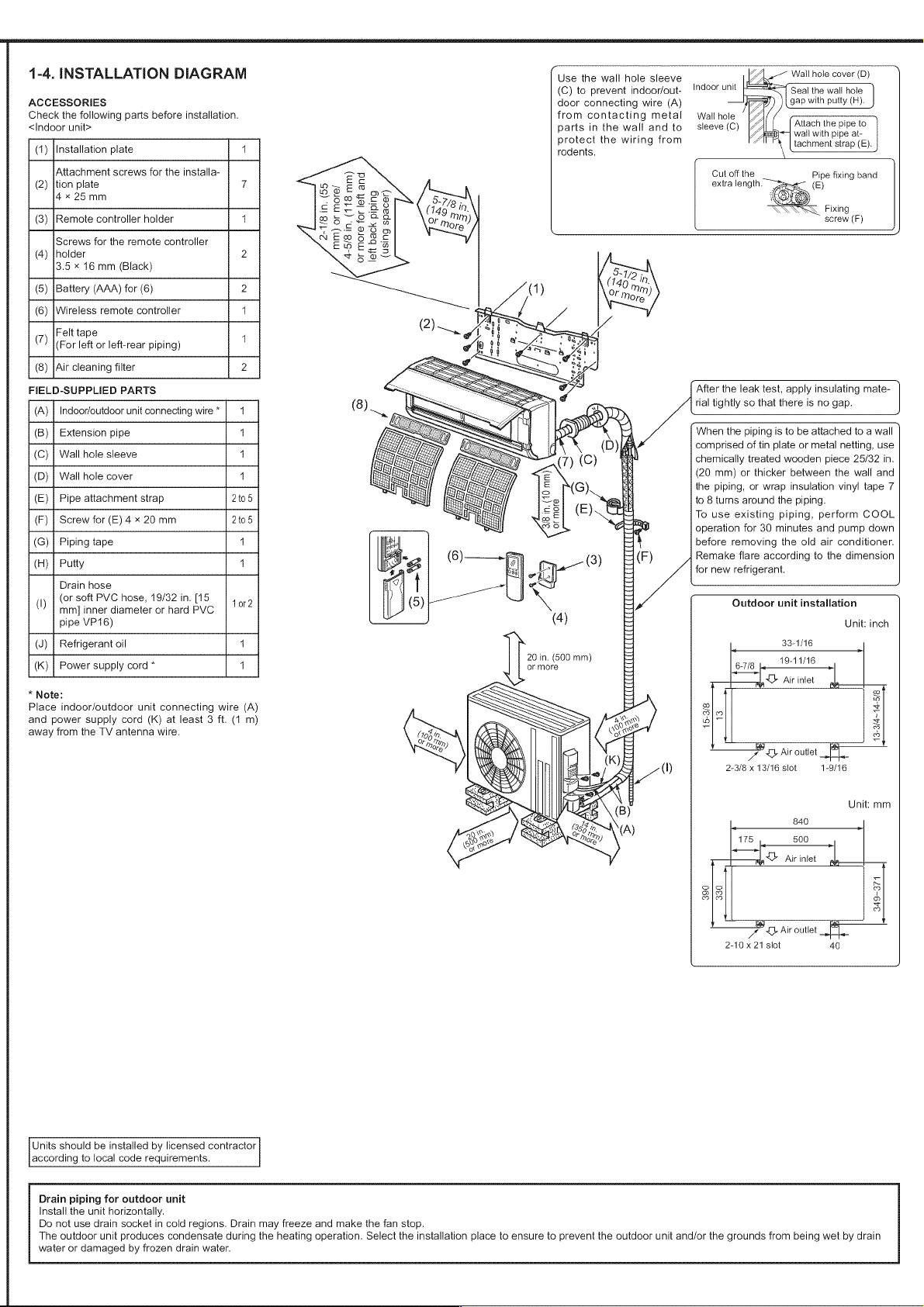
1-4.
INSTALLATION
DIAGRAM
ACCESSORIES
Check
the
following
parts
before
installation.
<[ndoor
unit>
(1)
[Installation
plate
4
Attachment
screws
for
the
installa-
(2)
|tion
plate
7
4*«
25mm
(3)
[Remote
controller
holder
1
Screws
for
the
remote
controller
(4)
|holder
2
3.5
x
16
mm
(Black)
(5)
{Battery
(AAA)
for
(6)
2
(6)
|Wireless
remote
controller
4
(7)
Felt
tape
1
(For
left
or
left-rear
piping)
(8)
[Air
cleaning
filter
2
FIELD-SUPPLIED
PARTS
(A)
|
Indoor/outdoor
unit
connecting
wire
*
4
(B)
|
Extension
pipe
4
(C)
|
Wall hole
sleeve
4
(D)
|
Wall hole
cover
4
(E)
|
Pipe
attachment
strap
2t05
(F)
|
Screw
for
(E)
4
x
20
mm
2t05
(G) |
Piping
tape
4
(H)
|
Putty
4
Drain
hose
(I)
(or
soft
PVC
hose,
19/32
in.
[15
tor?
mm]
inner
diameter
or
hard
PVC
pipe
VP16)
(J)
|
Refrigerant
oil
4
(K)
|
Power
supply
cord
*
4
*
Note:
Place
indoor/outdoor
unit
connecting
wire
(A)
and
power
supply
cord
(K)
at
least
3
ft.
(1
m)
away
from
the
TV
antenna
wire.
Units
should
be
installed
by
licensed
contractor
according
to
local
code
requirements.
2-1/8
in.
(55
mm)
or
more/
4-5/8
in.
(118
mm)
or
more
for
left
and
Use
the
wall
hole
sleeve
(C)
to
prevent
indoor/out-
door
connecting
wire
(A)
from
contacting
metal
parts
in
the
wall
and
to
protect
the
wiring
from
rodents.
indoor
unit
Seal
the
wail
hole
gap
with
putty
(R).
Wail
hole
sleeve
(C)
Attach
the
pipe
to
sca)
wall
with
pipe
at-
tachment
strap
(E).
Cut
off
the
Pipe
fixing
band
extra
length.
~~
(E)
Fixing
screw
(F)
left
back
piping
(using
spacer)
20
in.
(600
mm)
or
more
After
the
leak
test,
apply
insulating
mate-
rial
tightly
so
that
there
is
no
gap.
When
the
piping
is
to
be
attached
to
a
wall
comprised
of
tin
plate
or
metal
netting,
use
chemically
treated
wooden
piece
25/32
in.
(20
mm)
or
thicker
between
the
wall
and
the
piping,
or
wrap
insulation
vinyl
tape
7
to 8
turns
around
the
piping.
To
use
existing
piping,
perform
COOL
operation
for
30
minutes
and
pump
down
before
removing
the
old
air
conditioner.
Remake
flare
according
to
the
dimension
for
new
refrigerant.
Outdoor
unit
installation
Unit:
inch
33-1/16
19-11/16
6-7/8
be
aa
Air
infet
a
NAL
15-3/8
13
13-3/4~14-5/8
el
OD
Air
outlet
2-3/8
x
13/16
slot
1-9/16
Unit:
mm
390
330
nN
oD
2
D
=
oD
—+
Air
outlet
2-10
x
21
slot
40
Drain
piping
for
outdoor
unit
Install
the
unit
horizontally.
Do
not
use
drain
socket
in
cold
regions.
Drain
may
freeze
and
make
the fan
stop.
The
outdoor
unit
produces
condensate
during
the
heating
operation.
Select
the
installation
place
to
ensure
to
prevent
the
outdoor
unit
and/or
the
grounds
from
being
wet
by
drain
water
or
damaged
by
frozen
drain
water.
Loading ...
Loading ...
Loading ...