Loading ...
Loading ...
Loading ...
Your new tiller has been assembled at the factory with the exception of those parts left
unassembled for shipping purposes. To ensure safe and proper operation of your tiller
all parts and hardware you assemble must be tightened securely. Use the correct tools
as necessary to insure proper tightness.
TOOLS REQUIRED FOR
ASSEMBLY
A socket wrench set will make assembly
easier. Standard wrench sizes are listed.
(1) Utility knife
(2) 1/2 Wrench
OPERATOR'S POSITION
When right or left hand is mentioned in this
manual, it means when you are in the operat-
ing position (standing behind tiller handles).
Front
Left
Right
Operator's Position
UNPACK CARTON & INSTALL
HANDLE
_CAUTION: Be careful of exposed sta-
ples when handling or disposing of carton-
ing material.
IMPORTANT: When unpacking and as-
sembling tiller, be careful not to stretch or
kink cable(s).
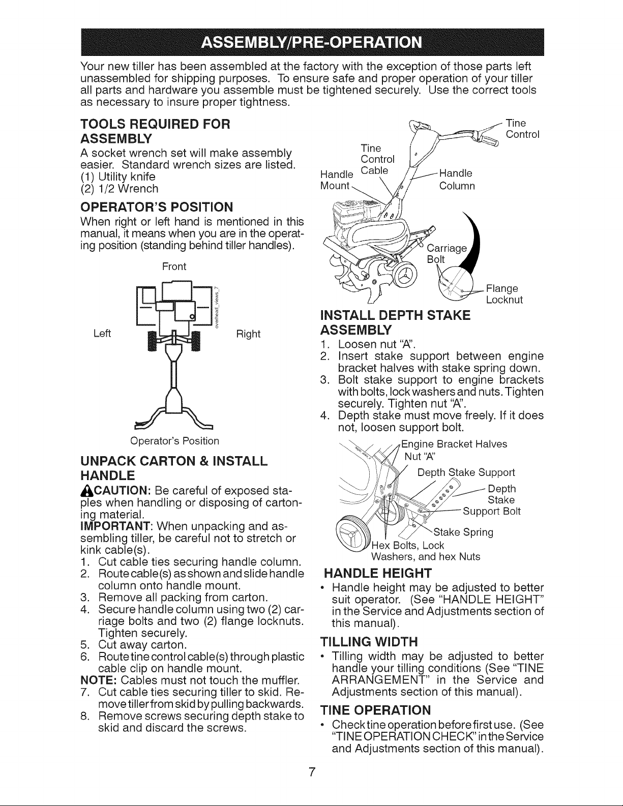
1. Cut cable ties securing handle column.
2. Route cable(s) as shown and slide handle
column onto handle mount.
3. Remove all packing from carton.
4. Secure handle column using two (2) car-
riage bolts and two (2) flange Iocknuts.
Tighten securely.
5. Cut away carton.
6. Routetine control cable(s) through plastic
cable clip on handle mount.
NOTE: Cables must not touch the muffler.
7. Cut cable ties securing tiller to skid. Re-
move tiller from skid by pulling backwards.
8. Remove screws securing depth stake to
skid and discard the screws.
Tine
Control
Handle Cable Handle
Column
Tine
Control
C .oa_ Flange
Locknut
INSTALL DEPTH STAKE
ASSEMBLY
1. Loosen nut'S'.
2. Insert stake support between engine
bracket halves with stake spring down.
3. Bolt stake support to engine brackets
with bolts, lock washers and nuts. Tighten
securely. Tighten nut '_'.
4. Depth stake must move freely. If it does
not, loosen support bolt.
ine Bracket Halves
Depth Stake Support
Depth
Stake
Support Bolt
Spring
Hex Bolts, Lock
Washers, and hex Nuts
HANDLE HEIGHT
• Handle height may be adjusted to better
suit operator. (See "HANDLE HEIGHT"
in the Service and Adjustments section of
this manual).
TILLING WIDTH
= Tilling width may be adjusted to better
handle your tilling conditions (See "TINE
ARRANGEMENT" in the Service and
Adjustments section of this manual).
T[NE OPERATION
• Checktine operation beforefirst use. (See
"TIN E OPE RATION CHECK" inthe Service
and Adjustments section of this manual).
7
Loading ...
Loading ...
Loading ...