Loading ...
Loading ...
Loading ...
49-5000041 Rev. 6
IMPORTANT
2QO\WUDLQHGTXDOLILHGSHUVRQQHOVKRXOGDFFHVVHOHFWULFDO
SDQHORQXQLWDQGLQVWDOOHOHFWULFDODFFHVVRULHV3OHDVH
contact your local electrical contractor, dealer, or
distributor for assistance.
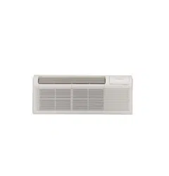
Thermostat Wire Routing
Thermostat wire is field supplied. Recommended wire
JDXJHLVWRJDXJHVROLGWKHUPRVWDWZLUH127(
,WLVUHFRPPHQGHGWKDWH[WUDZLUHVDUHUXQWRXQLWLQ
case any are damaged during installation. Thermostat
ZLUHVKRXOGDOZD\VEHURXWHGDURXQGRUXQGHU1(9(5
through, the wall sleeve. The wire should then be routed
behind the front panel to the easily accessible terminal
connector.
NOTE: Refer to thermostat installation instructions for
details on installing wall thermostat.
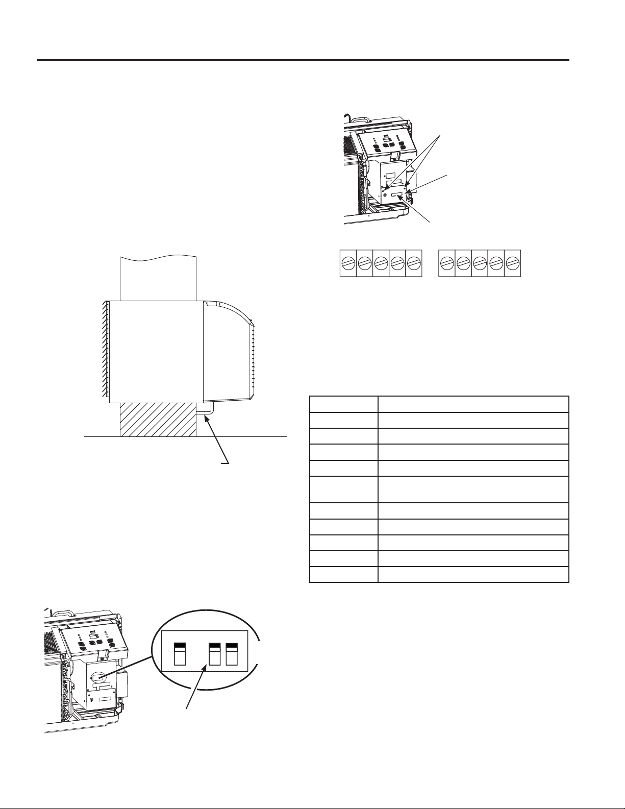
Wall Thermostat Enable
3RZHURIIWKHXQLW
• Unit must be powered OFF to change dip switch
settings.
)OLSWKH66DQG6GLSVZLWFKHVWRWKH8321
SRVLWLRQDVVKRZQEHORZ6HHSDJHIRUGLSVZLWFK
locations and functions.
Installation instruction for PTAC Thermostat
Remove the two screws as shown below and remove the
cover.
• Insert the wires from the wall thermostat into the correct
terminals according to manufacturers instructions.
Wall Thermostat Installation (Optional)
USING THE AIR CONDITIONER
Terminal Designation
)&/ )URQWGHVNFRQWUROWHUPLQDO/
)&1 )URQWGHVNFRQWUROWHUPLQDO1
/2:)$1 /RZIDQVSHHG*/
+,)$1 +LJKIDQVSHHG*+
:$<
ZD\YDOYH5HYHUVHF\FOH(QHUJL]HGLQ
+HDW)RUKHDWSXPSPRGHOV%
+($7 1RW8VHG
+($7 (OHFWULFDOKHDWHU:
&203 Compressor (Y)
91 9$&WHUPLQDO11HXWUDO&&RPPRQ
9/ 9$&WHUPLQDO/+275
7KHUPRVWDW:LUH5RXWLQJ
8QGHU6OHHYH%HKLQG)URQW3DQHO
3URSHU:LUH5RXWLQJ
%HQHDWK8QLW
'LS6ZLWFK
FC(L)
FC(N)
LOW-FAN
HI-FAN
4-WAY
HEAT2
HEAT1
COMP
24V(N)
24V(L)
Terminal of PTAC Wall Thermostat (MODE A)
Remove the 2 screws
Remove the covers
Thermostat connection
terminals
UP (on)
Down (off)
S5 S4 S3
Loading ...
Loading ...
Loading ...